Embed Size (px)
Citation preview
MODELLING THE ANISOTROPIC AND BIAXIAL CREEP BEHAVIOUR OF N&BASE SINGLE CRYSTAL SUPERALLOYS
CMSX-4 AND SRR99 AT 1223 K.
D.W. MacLachlan, L.W. Wright, S.S.K. Gunturi, and D.M. Knowles
Rolls Royce University Technology Centre Department of Materials Science & Metallurgy
University of Cambridge, UK.
Abstract
The use of single crystal turbine blade components has made many traditional models for creep unsuitable for application in certain loading situations. Such models generally assume deformation is isotropic. Since the introduction of single crystal components a generation of crystal plasticity or slip system models has emerged. Amongst the challenges of such models is to explain the orientation dependence of uniaxial creep behaviour and to attempt to make correlation between uniaxial and multiaxial stress states so that confidence can be’gained as to the performance of a model when it is applied to complex loading conditions. In this paper an attempt is made to address these issues. A slip system based finite element creep model has been fitted to uniaxial data at 1223 K in a range of crystallographic orientations. Based on experimental evidence the operative slip systems incorporated are the {111}<101> and {111}412> families of slip system.
Analysis of the data and a consideration of the dislocation mechanisms likely to occur suggest that the significant component of the hardening matrix is latent hardening by the {111}<101> systems on the { 11 1}<112> systems, although hardening between the { 11 l}<lOl> systems may also occur. The model can describe creep deformation as a function of orientation to a reasonable degree of accuracy. It is also shown to have reasonable predictive capability when used to analyse the results of thin cylinder biaxial creep tests on CMSX-4 and SRR99. The reason for this success is explained in terms of activated slip systems and the magnitude of the cumulative shear strain rate on different types of slip system as a function of orientation and stress state.
Superanoys zoo0 @ited by T.M. Pollock, R.D. Kissinger, R.R. Bowman,
K.A. Green, M. M&an, S. Olson, and J.J. Schirra TMS (The h4inemls. Metals & Materials Society), 2ooO
357
Introduction Table II Creep specimen orientations.
Single crystal Ni-base superalloys are commonly employed for use as high temperature creep and oxidation resistant blade alloys in the early stages of modern gas turbine aero-engines. CMSX-4 was developed for such an application by the Cannon-Muskegon Corporation [l]. The excellent high temperature creep properties of this superalloy are derived directly from its microstructure, consisting of 70% volume fraction of coherent, cuboidal y’- precipitates in a matrix of solid solution strengthened y-phase, which act as barriers to dislocation motion at high temperature. The large atomic radii elements MO, W and Re in CMSX-4 preferentially partition to the y-matrix [2]; causing the relative expansion of the y-lattice parameter compared with that of the y’- precipitates, hence CMSX-4 is a negative misfit alloy.
Test Nominal et P”T Test Stress Specimen Orientation Degrees Degrees Frpa]
53.2
53.5
52.2
51.5
50.8
53.3
The use of high strength, two phase, single crystal superalloys for blade materials has led to complex relationships between load, temperature and deformation. This is exacerbated by the complex geometry and anisotropy of blade components as well as the multiaxial stress states they experience. Accurate modelling of deformation occurring under such conditions has been highlighted as a requirement for optimising the efficiency in design of components, with respect to both preventing failure and avoiding over-design.
Materials and Methods
44.9
41.2
23.0
23.0
34.0
42.0
42.0
38.1
45.0 250
42.9 300
41.4 325
42.5 355
43.9 400
42.5 450
* 480
1.0 350
3.0 250
13.6 250
13.6 400
40.0 300
19.3 350
19.3 . 400
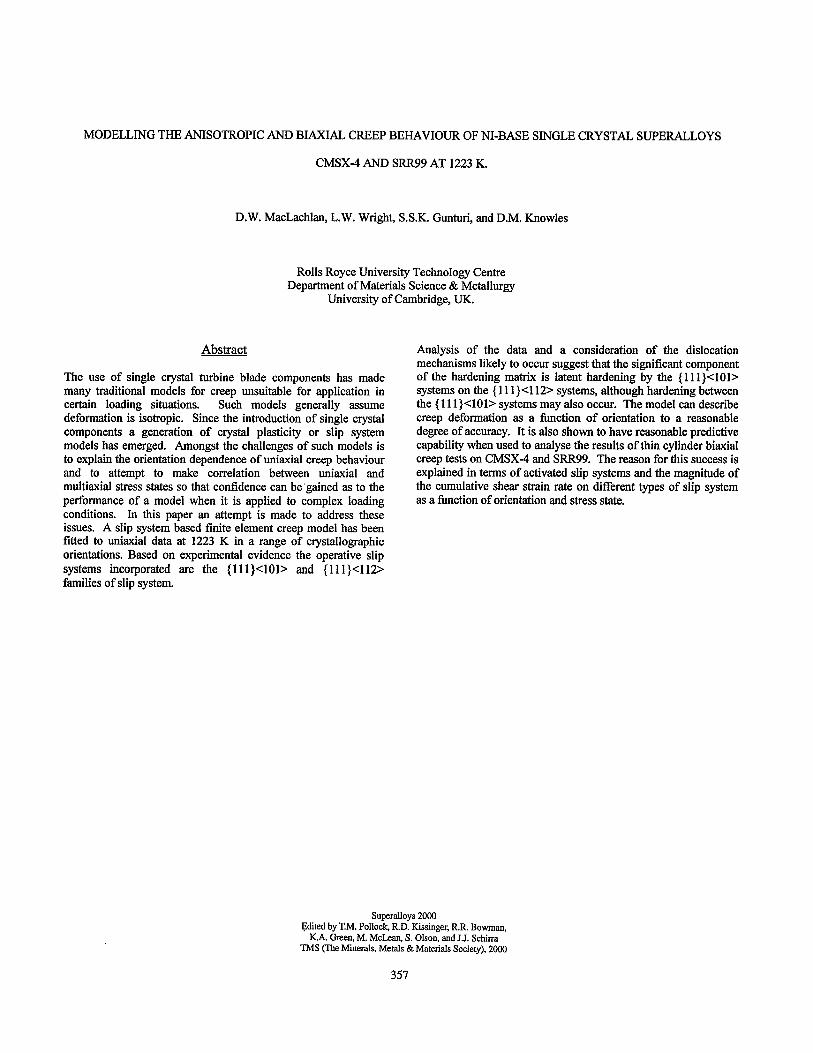
2.3 300 The standard creep specimens used in this study were machined from cast bars of CMSX4 supplied by Rolls-Royce plc. with compositions as given in Table I. The bars were seeded so as to give a number of different axis orientations. The orientations listed in table II and illustrated in figure 1 were determined using a backscattered Laue method [3].
A [iii]
B [ii11
C [ill]
D [ill]
E [ill]
F [ill]
CF PO11 H P111 I [i 19 231
J [I 4 lo]
K [I 4 lo]
L [ii21
M [%71 N [267]
0 [i 25 321
t The terms 8 and p are defined in figure 1. y This specimen was interrupted before rupture and its orientation was not measured. Additional creep data fiorn the Rolls-Royce database, for nominal < 001 > orientated specimens, were used for model development.
Table I Nominal compositions (wt. %) of CMSX4.
Ni Co Cr W MO Re Al Ti Ta Hf
Bal 9.7 6.5 6.4 0.6 2.9 5.6 1.0 6.5 0.1
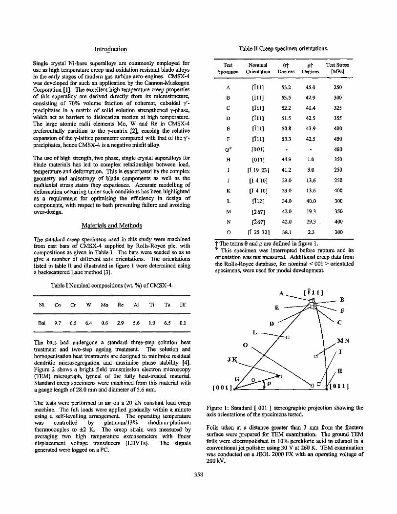
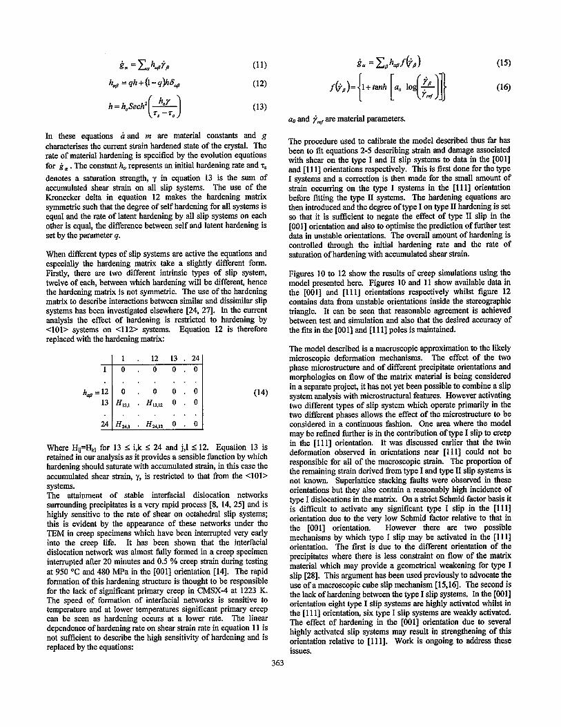
The bars had undergone a standard three-step solution heat treatment and two-step ageing treatment. The solution and homogenisation heat treatments are designed to minimise residual dendritic microsegregation and maximise phase stability [4]. Figure 2 shows a bright field transmission electron microscopy (TEM) micrograph, typical of the fully heat-treated material. Standard creep specimens were machined from this material with a gauge length of 28.0 mm and diameter of 5.6 mm.
The tests were performed in air on a 20 kN constant load creep machine. The full loads were applied gradually within a minute using a self-levelling arrangement. The operating temperature WaS controlled by platinum/l3% rhodium-platinum thermocouples to f2 K. The creep strain was measured by averaging two high temperature extensometers with linear displacement voltage transducers (LDVTs). The signals generated were logged on a PC.
Figure 1: Standard [ 001 ] stereographic projection showing the axis orientations of the specimens tested.
Foils taken at a distance greater than 3 mm from the fracture surface were prepared for TEM examination. The ground TEM foils were electropolished in 10% perchloric acid in ethanol in a conventional jet polisher using 30 V at 260 K. TEM examination was conducted on a JEOL 2000 FX with an operating voltage of 200 kV.
MN
I
358
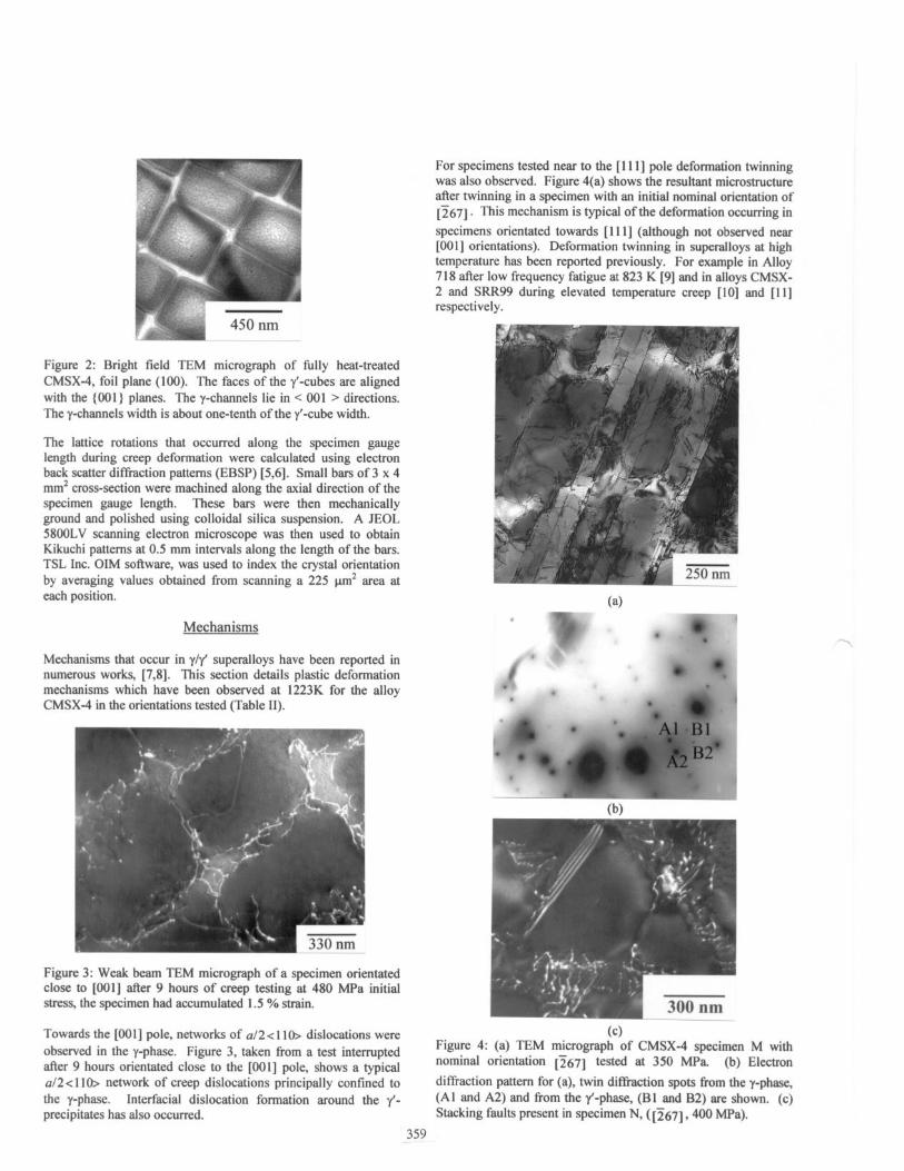
Figure 2: Bright field TEM micrograph of filly heat-treated CMSX-4, foil plane (100). The faces of the y’-cubes are aligned with the {OOl } planes. The y-channels lie in < 001 > directions. The y-channels width is about one-tenth of the y’-cube width.
The lattice rotations that occurred along the specimen gauge length during creep deformation were calculated using electron back scatter diffraction patterns (EBSP) [5,6]. Small bars of 3 x 4 mm* cross-section were machined along the axial direction of the specimen gauge length. These bars were then mechanically ground and polished using colloidal silica suspension. A JEOL 58OOLV scanning electron microscope was then used to obtain Kikuchi patterns at 0.5 mm intervals along the length of the bars. TSL Inc. OIM software, was used to index the crystal orientation by averaging values obtained from scanning a 225 pm’ area at each position.
Mechanisms
Mechanisms that occur in y/y’ superalloys have been reported in numerous works, [7,8]. This section details plastic deformation mechanisms which have been observed at 1223K for the alloy CMSX-4 in the orientations tested (Table II).
Figure 3: Weak beam TEM micrograph of a specimen orientated close to [OOI] after 9 hours of creep testing at 480 MPa initial stress, the specimen had accumulated I .5 % strain.
Towards the [OOl] pole, networks of a/2<1 lo> dislocations were observed in the y-phase. Figure 3, taken from a test interrupted after 9 hours orientated close to the [OOI] pole, shows a typical a/2< I lo> network of creep dislocations principally confined to the y-phase. Interfacial dislocation formation around the y’- precipitates has also occurred.
For specimens tested near to the [ 1 I I] pole deformation twinning was also observed. Figure 4(a) shows the resultant microstructure after twinning in a specimen with an initial nominal orientation of 12671. This mechanism is typical of the deformation occurring in specimens orientated towards [I I I] (although not observed near [OOI] orientations). Deformation twinning in super-alloys at high temperature has been reported previously. For example in Alloy 7 I8 after low frequency fatigue at 823 K [9] and in alloys CMSX- 2 and SRR99 during elevated temperature creep [lo] and [I I] respectively.
(4 ‘16 , v -I \
f e a
’ & l ‘. .-ALBl B2’
(b)
(cl Figure 4: (a) TEM micrograph of CMSX-4 specimen M with nominal orientation 12671 tested at 350 MPa (b) Electron diffraction pattern for (a), twin diffraction spots from the y-phase, (Al and A2) and from the y’-phase, (Bl and B2) are shown. (c) Stacking faults present in specimen N, ([267], 400 MPa).
359
Common with slip deformation, the shearing of a crystal resulting from deformation by twinning enables it to undergo a plastic deformation. The fixed magnitude of the twinning shears shown in figure 4(a) results in the reorientation of parts of the crystal. The orientation relationship of the original crystal and the twinned parts can be obtained from the electron difbaction pattern figure 4(b). The pairs of difI?action spots in the pattern indicate that twinning has occurred. Additionally, the larger pairs of diffraction spots, (e.g. Al and A2) show that twinning has occurred in the y-phase, while the fainter pairs of diffraction spots, (e.g. Bl and B2) show that twinning has also occurred in the y’- phase.
The deformation twins thus extend through the y/y’ microstructure twinning both the y and y’ phases. For twining in a FCC, face centred cubic, phase a deformation twin occurs by sliding adjacent (111) planes by a/6[112] resulting in a shear s of magnitude l/42. In a Liz structure however twinning requires the passage of a dislocation with twice this magnitude, giving A2 [12]. Such a shear also produces a twin in the FCC lattice, but is not generally observed for energetic reasons. As the twins observed in CMSX- 4 are continuous through both phases it would appear that they are the result of the passage of a/3<112> dislocations through the whole structure. The amount of longitudinal plastic strain resulting from deformation twinning is: [ 131
E, = y,(J(l+yz co? (+2~cos4cosa)-l) (1)
where: ap is the plastic strain associated with twinning; Vf is the volume fraction of twins in the crystal; y is the shear strain; 4 is the angle between the tensile axis and slip plane normal and h is the angle between the tensile axis and the slip direction. From Table II, for specimen M, the relation between the nominal tensile axis ~2671 and the most highly resolved system for this orientation (11 I)121 11, gives $ = 47.7 o and h = 42.6 O, with y as 42, thus from equation 1, every one percent volume fraction of twins in the specimen contributes 0.8 % to the longitudinal strain.
[iii]
x Initial Orientation
A Final OrientatiOn
[Olll
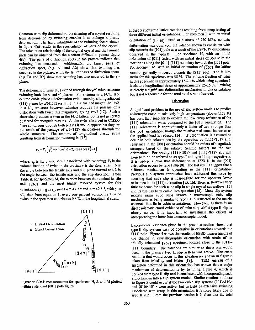
Figure 5: EBSP measurements for specimens H, J, and M plotted within a standard [OOl] pole figure.
Figure 5 shows the lattice rotations resulting from creep testing of three different initial orientations. For specimen J, with an initial orientation of [I 4 IO] tested at a stress of 250 MPa, no twin deformation was observed, the rotation shown is consistent with slip towards the [loll pole as a result of the a/2<101> dislocations observed in the y-phase. For specimen H, with an initial orientation of [Oil] tested with an initial stress of 350 MPa the rotation is along the [01 l]-[ll l] boundary towards the [ll l] pole. For specimen M, with an initial orientation of [267] the lattice rotation generally proceeds towards the [211] pole. The failure strain for this specimen was 35 %. The volume fraction of twins in this specimen is approximately 15-20 % which using equation 1 leads to a longitudinal strain of approximately 12-15 %. Twining is clearly a significant deformation mechanism in this orientation but is not responsible for the total axial strain observed.
Discussion
A significant problem in the use of slip system models to predict anisotropic creep at relatively high temperatures (above 1173 K) has been their inability to explain the low creep resistance of the [1 1 l] orientation when compared to the [OOl] orientation. The [I 1 l] orientation is approximately a factor of two stronger than the [OOl] orientation, though the relative resistance increases as the applied load is reduced [14]. If deformation is assumed to occur in both orientations by the operation of { 11 l}<lOl> slip, resistance in the [OOI] orientation should be orders of magnitude stronger, based on the relative Schmid factors for the two orientations. For brevity { 11 l}<lOl> and { 11 1}<112> slip will from here on be referred to as type I and type II slip respectively. It is widely known that deformation at 1223 K in the [OOl] orientation occurs by type I slip [8]. The test results suggest that a different mechanism is operating in the [l 1 l] orientation. Previous slip system approaches have addressed this issue by asserting that cube slip is responsible for the apparent lower resistance in the [ 1111 orientation [ 15, 161. There is, however very little evidence for such cube slip in single crystal superalloys [ 17] and its use has been called into question 1181. Many slip system models using cube slips invoke a macroscopic cube slip mechanism as being similar to type I slip restricted to the matrix channels that lie in cubic orientations. However, as there is no direct microstructural evidence of cube slip, whilst type II slip is clearly active, it is important to investigate the effects of incorporating the latter into a macroscopic model.
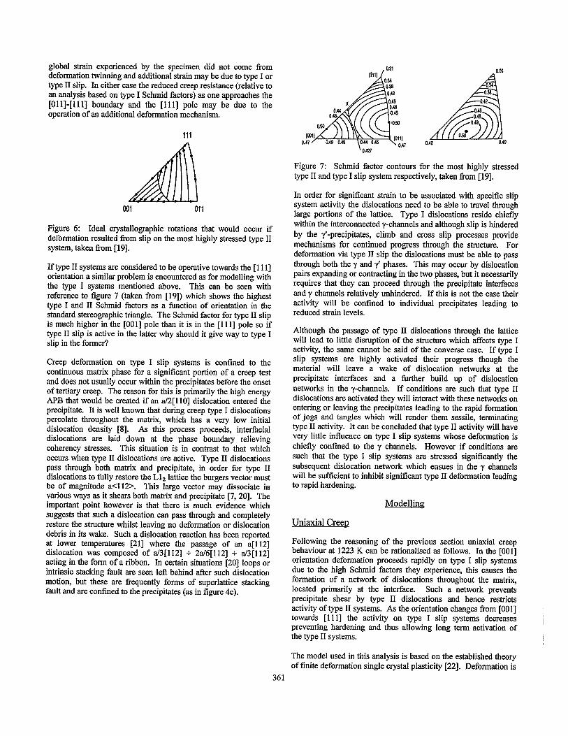
Experimental evidence given in the previous section shows that type II slip systems may be operative in orientations towards the [1 111 pole. Figure 5 shows the results of EBSD measurements of the change in crystallographic orientation with strain of an initially orientated 12671 specimen located close to the [Oil]- [1 1 l] boundary. The rotations are similar to those that would occur if the primary type II slip system was active. The exact rotations that would occur in this situation are shown in figure 6 taken from MacKay and Maier [ 191. TEM analysis of a specimen deformed in this orientation has shown that a major mechanism of deformation is by twinning, figure 4, which is derived from type II slip and is consistent with incorporating such a mechanism into a slip system model. Similar rotations to those in figure 5 could occur if the two cubic slip systems (OOl)<l lO> and (OlO)<lOl> were active, but in light of extensive twinning associated with creep in this orientation it is more likely due to type II slip. From the previous section it is clear that the total
360
global strain experienced by the specimen did not come from deformation twinning and additional strain may be due to type I or type II slip. In either case the reduced creep resistance (relative to an analysis based on type I S&mid factors) as one approaches the [Oil]-[Ill] boundary and the [Ill] pole may be due to the operation of an additional deformation mechanism.
Figure 6: Ideal crystallographic rotations that would occur if deformation resulted from slip on the most highly stressed type II system, taken f?om [ 191.
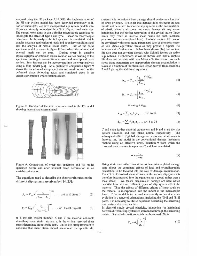
If type II systems are considered to be operative towards the [I 1 l] orientation a similar problem is encountered as for modelling with the type I systems mentioned above. This can be seen with reference to figure 7 (taken from [19]) which shows the highest type I and II S&mid factors as a function of orientation in the standard stereographic triangle. The S&mid factor for type II slip is much higher in the [OOl] pole than it is in the [ 11 l] pole so if type II slip is active in the latter why should it give way to type I slip in the former?
Creep deformation on type I slip systems is confined to the continuous matrix phase for a significant portion of a creep test and does not usually occur within the precipitates before the onset of tertiary creep. The reason for this is primarily the high energy APB that would be created if an a/2[1 lo] dislocation entered the precipitate. It is well known that during creep type I dislocations percolate throughout the matrix, which has a very low initial dislocation density [S]. As this process proceeds, interfacial dislocations are laid down at the phase boundary relieving coherency stresses. This situation is in contrast to that which occurs when type II dislocations are active. Type II dislocations pass through both matrix and precipitate, in order for type II dislocations to fully restore the Lls lattice the burgers vector must be of magnitude a<112>. This large vector may dissociate in various ways as it shears both matrix and precipitate [7, 201. The important point however is that there is much evidence which suggests that such a dislocation can pass through and completely restore the structure whilst leaving no deformation or dislocation debris in its wake. Such a dislocation reaction has been reported at lower temperatures [21] where the passage of an a[1 121 dislocation was composed of a/3[112] + 2a/6[112] + a/3[112] acting in the form of a ribbon. In certain situations [20] loops or intrinsic stacking fault are seen left behind alter such dislocation motion, but these are frequently forms of superlattice stacking fault and are confined to the precipitates (as in figure 4~).
361
Figure 7: Schmid factor contours for the most highly stressed type II and type I slip system respectively, taken from [19].
In order for significant strain to be associated with specific slip system activity the dislocations need to be able to travel through large portions of the lattice. Type I dislocations reside chiefly within the interconnected y-channels and although slip is hindered by the y’-precipitates, climb and cross slip processes provide mechanisms for continued progress through the structure. For deformation via type II slip the dislocations must be able to pass through both the y and 7’ phases. This may occur by dislocation pairs expanding or contracting in the two phases, but it necessarily requires that they can proceed through the precipitate interfaces and y channels relatively unhindered. If this is not the case their activity will be confined to individual precipitates leading to reduced strain levels.
Although the passage of type II dislocations through the lattice will lead to little disruption of the structure which affects type I activity, the same cannot be said of the converse case. If type I slip systems are highly activated their progress though the material will leave a wake of dislocation networks at the precipitate interfaces and a further build up of dislocation networks in the y-channels. If conditions are such that type II dislocations are activated they will interact with these networks on entering or leaving the precipitates leading to the rapid formation of jogs and tangles which will render them sessile, terminating type II activity. It can be concluded that type II activity will have very little influence on type I slip systems whose deformation is chiefly confined to the y channels. However if conditions are such that the type I slip systems are stressed significantly the subsequent dislocation network which ensues in the y channels will be sufficient to inhibit significant type II deformation leading to rapid hardening.
Uniaxial Creep
Following the reasoning of the previous section uniaxial creep behaviour at 1223 K can be rationalised as follows. In the [OOl] orientation deformation proceeds rapidly on type I slip systems due to the high Schmid factors they experience, this causes the formation of a network of dislocations throughout the matrix, located primarily at the interface. Such a network prevents precipitate shear by type II dislocations and hence restricts activity of type II systems. As the orientation changes from [OOl] towards [l 1 l] the activity on type I slip systems decreases preventing hardening and thus allowing long term activation of I
the type II systems.
The model used in this analysis is based on the established theory of finite deformation single crystal plasticity [22]. Deformation is
(or)
:s! [9z] pasn uaaq seq q~!q~ suogenba3o las au0 *X~IXII %quap~eq aq~ q?lnom paDnponu! s! sura~ss9 d!ls waJa#!p uaamaq (%u!uapJeq JO) uo!lD3Jalu! ‘rC1gsEld @IS,& al%u!s le~!ssap UI
-Jayrea passnwp sws!ueq3at.u %!uapreq atp %u!qysap suo!]enba wlpn 01 hssa3au s! 1! ‘salad [ 11 I] pue [roe] aw %u!pnlou! ‘suo!lelua!.ro 30 a%w e tq uo!lnloAa ms aqpsap 01 Xpuaqsuo:, pasn aq 01 s! lapow av 31 *laAal 3!doDsoJX?w aqI @ [aporn ayl olu! palEJodJoXq s! le!Jawu aql uo uws reaqs 30 su$?po luaJa33!p 30 si3a33a aql snqL *p+Jalt?w ag 13a33a walsk d!ls 30 sadXl 1uaJagp uo d!ls Moq aqu3sap q3!qAt pasn aJE a%EurEp 30 saJnSeaw Josual OML -19a33a ~301 e veq~ Jaqvu pz?qolZ t! SE suogvnba aql OIU! patEJodJow! aJo3aJayl s! stua]s,k dgs snowA aw uo sassaqs JEaqs paAlosaJ 30 laaga au wo!~lnurnwv a%Eurep 30 alar aql olu! pa-rolcw3 aq 01 uo!lelua!Jo cvqdtiol@tsh put? pool 30 sva33a pawqwo:, atp srno~~e alms a%Eurep @qol% e aupwalap 03 ssaJls ueql Jaqw alw u!v.us %u!sn
(6) m-1 -=D
OD
‘paltqwlE3 aJE E pue z suo!vnba u! sassans reaqs paAlosaJ aq qNqM uroy 6 uoftenba ‘ssans aA!pajJa ue %u!sn poylaw ss!ueqaaw a8E‘eurap @uo!luaAuo:, ayl u! lapow ay) oiu! paJol3a3 s! salEJ uws pue ssaqs uo a%Eurap lEqol% 30 iaa33a iuanbasqns
w *XlaA!tDadsaJ @uuou aueld d!ls pue uop3aJ!p wawk d!ls aq aJe u pue q pw slapuwvd @!JaiEru Jawy an A puv 3
(9) Z”, + ‘O’, = $3
:suogEnba @uo!l!pp?? aql %!A@! E pue z suo!tenba tuog paApap Josun alw ufws aql30 uo!lxty e se uam s! uogelnuuwn a%Eurep alepdoJddEu! an sJa)aurwed paseq ssaqs q3ns sy *ssaas aqoaga sas!w UOA W!M alalauo:, lou saop a3g aJnldn.I @!xwq ‘JalEl uMoqs aq II!M SE ‘aJoI.uJaqlJn~ Xualsk dgs ayw2 uo ~~013~3 py.uq3s V!M ICpDaJ!p aIElaJJo3 IOU saop OS@ ap1 amldru YEW [pl] uMoqs uaaq seq 11 *uo!laluauo 30 luapuadapu! a3g amldru E p!paJd xaql se ssans lualEA!nba sas!w UOA JO Josual ssaqs aql SE qDns sJalaun%ud paseq SsaJls ~J!M pa]elaJJo3 aq ]ouue:, a3g aJnldru le!xe!un .(aJaq paJap!suo3 lou an SassacioJd pas!@301 qDns lnq spueq reaqs asuaw! u! IlnsaJ hu upns a%nq) a3yq pzph3 ayl30 uogeJolsaJ lctaJ”ad aql lnq (%gIapJEq asnED hu t!) a%EruEp asnED IOU saop ugs JEaqs 3pseld 30 uogelnwnzw aw SE surawk dgs Drjpads 01 paielaJ aq IOU plnoqs pue ‘uo Jn330 IOU saop aF?Eeurep IEyl real:, s! 11 TIERS JO ssam 30 uogwy E SE aAloAa plnoqs a%urep moq luap!Aa IOU s! l! maids
dgs 3rJ!aads uo alepxun~3a plnoqs U!EJIS reaqs lt~ql apnlouo3 01 p.n2huo31q8~~s S! I! lsl!qM *sisal al!sual wag pau!uualap ssa.qs leaqs paA[osaJ lE5!1!~3 ag3 s! 3 pm aw up2.m maqs %u!q!.map slu~suo:, pamu am n pue g ‘Jaqwnu walsds dqs ayl s! x)
: [ sz ‘pi] Icq ua@ CUE su~a~slcs dqs )wxagp aql uo sa$w upx~s leaqs arl] aqgsap 01 pasn suogmba aqL
ue u! uo!leuuo3ap daaJ3 @!xe!un Jav puv aJo3aq uaw!jads lapom ga pue uaurpads lsal daaJ9 30 uos!redruoD :6 aJnQ
P
.qsam pzwJa?xa pue puralu! %u!moqs lapow 3~ aq u! pasn uauqaads pgos av 30 3lEq-au0 :g aJn%g
wk330 uo!luloJ aJaqM uogmuapo alqmsun III? II! daaJ3 palElnuqs pue @mX %U!MOIIO~ adaqs paurro3ap am se IlaM se qsaw pue uawpads daal:, pauuo3apun aql smoqs 6 aJn8g uos!Jvduro:, aA!IEvlanb a sv ‘[Ez] lapow pgos e lu!sn s!s~lEue daaJ3 aw olu! pa$eJodJoDu! aq ue3 SaJnIey q3ns -uo!lzias SSOJD lwld!lla ue pun sassaqs wo3!un-uou u! %u!llnsaJ uam!Dads aw 30 %u!puaq sasna:, uo!lulo~ 3!lst?la suogelua!Jo xqde.8olpzlsL.t~ alqetsun II! daaJ:, %uuna *uaas aq ue3 qsaw lerualxa pue pztwalu! aql q3!qM w0.g 8 a&g u! uAioqs s! lapour uampads P!los aql Jo 3leH *saws ssaJl-3 le!xe!q 30 s!slClaue aql osle pue suop!puo~ hrapunoq pun spool 30 uogexldde alEJnD3a salqeua q%qM ‘pa$Elntu!s s! uatu!Dads lly aq1 S!S&XIV aql UI *Jno!At?qaq c?!do%oJDE,em uo JEaqs 11 ad4 put? I ad4 30 lDa33a aq) ale%gsaAu! 01 anb!uqDal D!dODSOJDEtXI -rel!uqs E asn 01 sru!r! 7~0~ ]uaJJn:, am ‘dgs aqn:, pue l ad4 30 laa33a aqi asL@ue 01 +w.u!rd sap03 3s OIU! slapow walslcs dgs paleJodJo3u! aAeq [vz ‘EZ] sa!pnls Jayreg -[PI] @no!AaJd paq!JDsap uaaq seq lapotu rua@ d!Is 3,~ aw 30 uo!leluawa[dw! aql ‘snbvw a%:e?%d 3.~ aq1 %u!sn pas+ue
i, = C,h&9 hM =qh+(l-q)hs,,
(11)
(12)
In these equations ti and m are material constants and g characterises the current strain hardened state of the crystal. The rate of material hardening is specified by the evolution equations for i, . The constant h, represents an initial hardening rate and 5 denotes a saturation strength, y in equation 13 is the sum of accumulated shear strain on all slip systems. The use of the Kronecker delta in equation 12 makes the hardening matrix symmetric such that the degree of self hardening for all systems is equal and the rate of latent hardening by all slip systems on each other is equal, the difference between self and latent hardening is set by the parameter q.
When different types of slip systems are active the equations and especially the hardening matrix take a slightly different form. Firstly, there are two different intrinsic types of slip system, twelve of each, between which hardening will be different, hence the hardening matrix is not symmetric. The use of the hardening matrix to describe interactions between similar and dissimilar slip systems has been investigated elsewhere [24, 271. In the current analysis the effect of hardening is restricted to hardening by <lOl> systems on <112> systems. Equation 12 is therefore replaced with the hardening matrix:
-i
h,=l2 13
24 -
1 . 12 13 . 24
0. 0 0.0
. . . . . .
0. 0 0.0
H * 13.1 H 13.12 0.0 . . . . . .
H 24.1 . H 0.0 24.12
(14)
Where Hij=Hkt for 13 s i,k I 24 and j,l I 12. Equation 13 is retained in our analysis as it provides a sensible function by which hardening should saturate with accumulated strain, in this case the accumulated shear strain, 1: is restricted to that from the <lOl> systems. The attainment of stable interfacial dislocation networks surrounding precipitates is a very rapid process [8, 14, 251 and is highly sensitive to the rate of shear on octahedral slip systems; this is evident by the appearance of these networks under the TEM in creep specimens which have been interrupted very early into the creep life. It has been shown that the interfacial dislocation network was almost fully formed in a creep specimen interrupted after 20 minutes and 0.5 % creep strain during testing at 950 OC and 480 h4F’a in the [OOl] orientation [14]. The rapid formation of this hardening structure is thought to be responsible for the lack of significant primary creep in CMSX-4 at 1223 K. The speed of formation of interfacial networks is sensitive to temperature and at lower temperatures significant primary creep can be seen as hardening occurs at a lower rate. The linear dependence of hardening rate on shear strain rate in equation 11 is not sufficient to describe the high sensitivity of hardening and is replaced by the equations:
363
!A = C,h,fG;/J
&p)=~+tanh [uo b(e]]}
(15)
(16)
a0 and imr/ are material parameters.
The procedure used to calibrate the model described thus far has been to fit equations 2-5 describing strain and damage associated with shear on the type I and II slip systems to data in the [OOI] and [ 11 l] orientations respectively. This is first done for the type I systems and a correction is then made for the small amount of strain occurring on the type I systems in the [I 1 l] orientation before fitting the type II systems. The hardening equations are then introduced and the degree of type I on type II hardening is set so that it is sufficient to negate the effect of type II slip in the [OOI] orientation and also to optimise the prediction of further test data in unstable orientations. The overall amount of hardening is controlled through the initial hardening rate and the rate of saturation of hardening with accumulated shear strain.
Figures 10 to 12 show the results of creep simulations using the model presented here. Figures 10 and 11 show available data in the [OOl] and [ill] orientations respectively whilst figure 12 contains data from unstable orientations inside the stereographic triangle. It can be seen that reasonable agreement is achieved between test and simulation and also that the desired accuracy of the fits in the [OOl] and [l 1 l] poles is maintained.
The model described is a macroscopic approximation to the likely microscopic deformation mechanisms. The effect of the two
phase microstructure and of different precipitate orientations and morphologies on flow of the matrix material is being considered in a separate project, it has not yet been possible to combine a slip system analysis with microstructural features. However activating two different types of slip system which operate primarily in the two different phases allows the effect of the microstructure to be considered in a continuous fashion. One area where the model may be refined further is in the contribution of type I slip to creep in the [I 1 l] orientation. It was discussed earlier that the twin deformation observed in orientations near [ill] could not be responsible for all of the macroscopic strain. The proportion of the remaining strain derived from type I and type II slip systems is not known. Superlattice stacking faults were observed in these orientations but they also contain a reasonably high incidence of type I dislocations in the matrix. On a strict Schmid factor basis it is difficult to activate any significant type I slip in the [ill] orientation due to the very low Schmid factor relative to that in the [OOI] orientation. However there are two possible mechanisms by which type I slip may be activated in the [ 11 I] orientation. The first is due to the different orientation of the precipitates where there is less constraint on flow of the matrix material which may provide a geometrical weakening for type I slip [28]. This argument has been used previously to advocate the use of a macroscopic cube slip mechanism [15,16]. The second is the lack of hardening between the type I slip systems. In the [OOl] orientation eight type I slip systems are highly activated whilst in the [ 11 l] orientation, six type I slip systems are weakly activated. The effect of hardening in the [OOl] orientation due to several highly activated slip systems may result in strengthening of this orientation relative to [ 1111. Work is ongoing to address these issues.
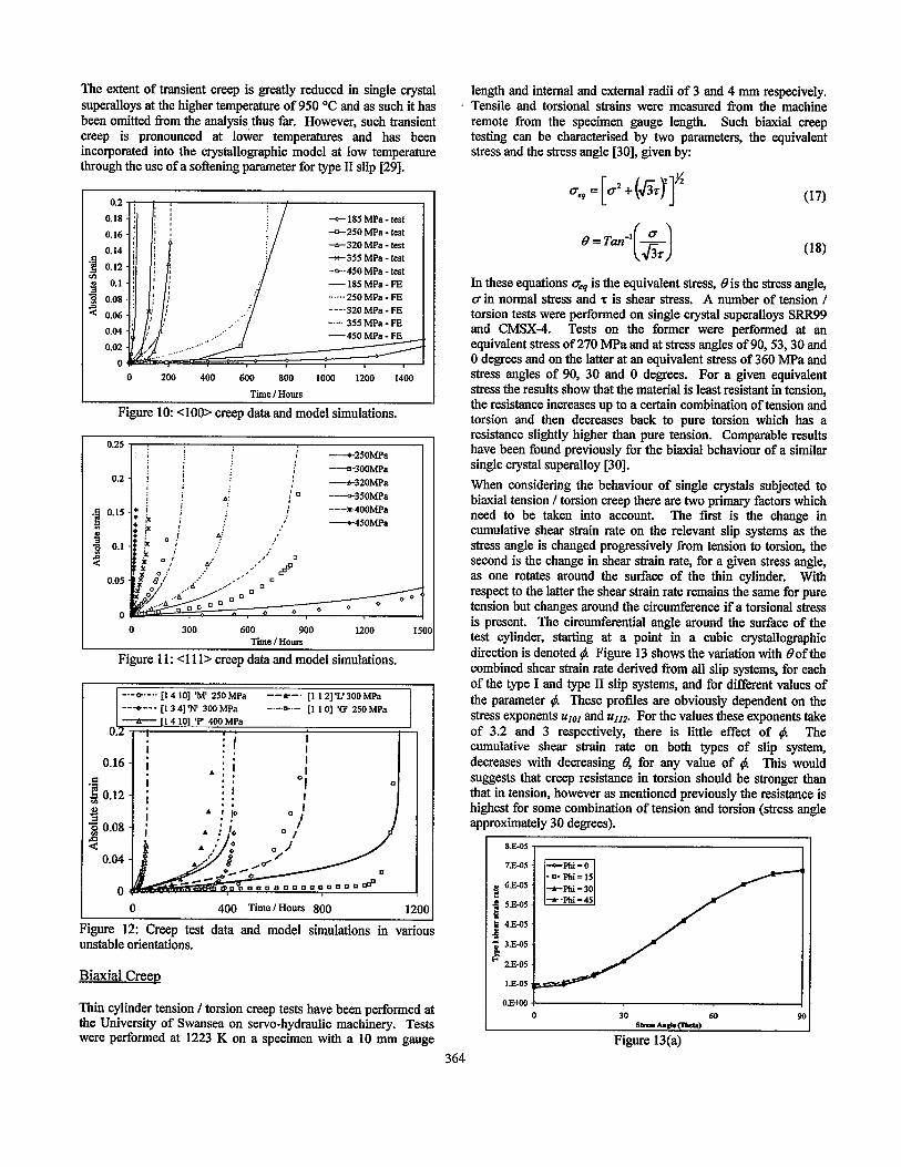
The extent of transient creep is greatly reduced in single crystal superalloys at the higher temperature of 950 OC and as such it has been omitted from the analysis thus far. However, such transient creep is pronounced at lower temperatures and has been incorporated into the crystallographic model at low temperature through the use of a softening parameter for type II slip [29].
0.2
0.18
0.16 -=-250 MPa - test
4320 MPa test - 0.14 *355 MPa - test
0.12 --450 MPa - test
g 0.1 -185MPa-FE
51 0.08 . . . . ..25OMPa-FE
9 0.06
0.04
0.02
0
0 200 400 600 800 1000 1200 1400
Tic I Hours
Figure 10: x100> creep data and model simulations.
Time I Hours
Figure 11: ~11 l> creep data and model simulations.
Figure 12: Creep test data and model simulations in various unstable orientations.
Biaxial Creer,
Thin cylinder tension /torsion creep tests have been performed at the University of Swansea on servo-hydraulic machinery. Tests were performed at 1223 K on a specimen with a 10 mm gauge
364
length and internal and external radii of 3 and 4 mm respecively. Tensile and torsional strains were measured from the machine remote Erom the specimen gauge length. Such biaxial creep testing can be characterised by two parameters, the equivalent stress and the stress angle [30], given by:
(17)
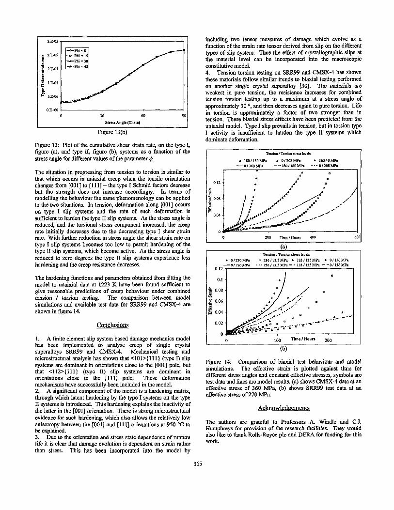
In these equations qr is the equivalent stress, 0 is the stress angle, cr in normal stress and z is shear stress. A number of tension / torsion tests were performed on single crystal superalloys SKK99 and CMSX-4. Tests on the former were performed at an equivalent stress of 270 MPa and at stress angles of 90,53,30 and 0 degrees and on the latter at an equivalent stress of 360 MPa and stress angles of 90, 30 and 0 degrees. For a given equivalent stress the results show that the material is least resistant in tension, the resistance increases up to a certain combination of tension and torsion and then decreases back to pure torsion which has a resistance slightly higher than pure tension. Comparable results have been found previously for the biaxial behaviour of a similar single crystal superalloy [30]. When considering the behaviour of single crystals subjected to biaxial tension / torsion creep there are two primary factors which need to be taken into account. The fust is the change in cumulative shear strain rate on the relevant slip systems as the stress angle is changed progressively from tension to torsion, the second is the change in shear strain rate, for a given stress angle, as one rotates around the surface of the thin cylinder. With respect to the latter the shear strain rate remains the same for pure tension but changes around the circumference if a torsional stress is present. The circumferential angle around the surface of the test cylinder, starting at a point in a cubic crystallographic direction is denoted 4. Figure 13 shows the variation with @of the combined shear strain rate derived from all slip systems, for each of the type I and type II slip systems, and for different values of the parameter 4. These profiles are obviously dependent on the stress exponents ulol and ~4112. For the values these exponents take of 3.2 and 3 respectively, there is little effect of 4 The cumulative shear strain rate on both types of slip system, decreases with decreasing 0, for any value of #. This would suggests that creep resistance in torsion should be stronger than that in tension, however as mentioned previously the resistance is highest for some combination of tension and torsion (stress angle approximately 30 degrees).
O.EtOO I n 30 60 90 ”
.Q-~bePUd
Figure 13(a)
3.E-05
L
0 2.E-05 c
8 2.E-05
c * l.E-05 E 8.
F 5.E-06
O.E+OO
0 30 60 90
Strear Angle (Theta)
Figure 13(b)
Figure 13: Plot of the cumulative shear strain rate, on the type I, figure (a), and type II, figure (b), systems as a flmction of the stress angle for different values of the parameter 4
The situation in progressing from tension to torsion is similar to that which occurs in uniaxial creep when the tensile orientation changes from [OOI J to [ 111]- the type I Schmid factors decrease but the strength does not increase accordingly. In terms of modelling the behaviour the same phenomenology can be applied to the two situations. In tension, deformation along [OOl] occurs on type I slip systems and the rate of such deformation is sufficient to harden the type II slip systems. As the stress angle is reduced, and the torsional stress component increased, the creep rate initially decreases due to the decreasing type I shear strain rate. With further reduction in stress angle the shear strain rate on type I slip systems becomes too low to permit hardening of the type II slip systems, which become active. As the stress angle is reduced to zero degrees the type II slip systems experience less hardening and the creep resistance decreases.
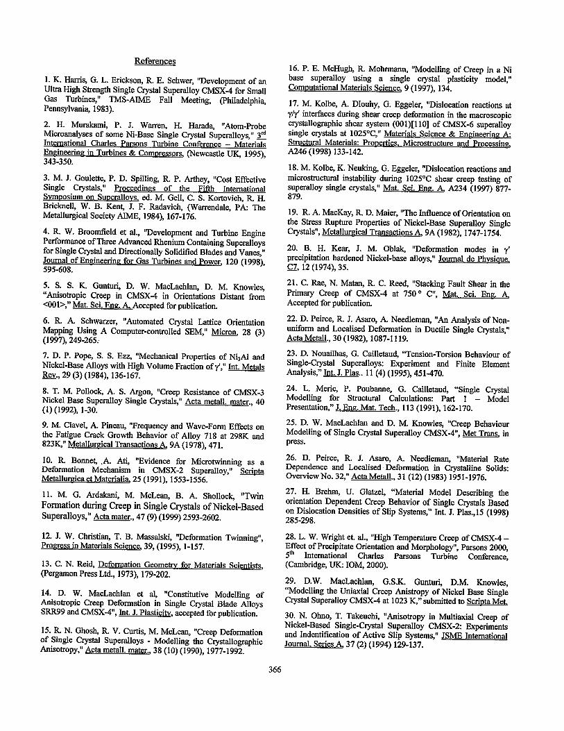
The hardening functions and parameters obtained from fitting the model to unaixial data at 1223 K have been found sufficient to give reasonable predictions of creep behaviour under combined tension I torsion testing. The comparison between model simulations and available test data for SRR99 and CMSX-4 are shown in figure 14.
Conclusions
1. A finite element slip system based damage mechanics model has been implemented to analyse creep of single crystal superalloys SRR99 and CMSX4. Mechanical testing and microstructural analysis has shown that <lOl>{ 111) (type I) slip systems are dominant in orientations close to the [OOl] pole, but that <112>{ 111) (type II) slip systems are dominant in orientations close to the [l 1 l] pole. These deformation mechanisms have successfully been included in the model. 2. A significant component of the model is a hardening matrix, through which latent hardening by the type I systems on the type II systems is introduced. This hardening explains the inactivity of the latter in the [OOl] orientation. There is strong microstructural evidence for such hardening, which also allows the relatively low anisotropy between the [OOl] and [ 11 l] orientations at 950 OC to be explained. 3. Due to the orientation and stress state dependence of rupture life it is clear that damage evolution is dependent on strain rather than stress. This has been incorporated into the model by
including two tensor measures of damage which evolve as a function of the strain rate tensor derived from slip on the different types of slip system. Thus the effect of crystallographic slips at the material level can be incorporated into the macroscopic constitutive model. 4. Tension torsion testing on SRR99 and CMSX-4 has shown these materials follow similar trends to biaxial testing performed on another single crystal superalloy [30]. The materials are weakest in pure tension, the resistance increases for combined tension torsion testing up to a maximum at a stress angle of approximately 30 “, and then decreases again to pure torsion. Life in torsion is approximately a factor of two stronger than in tension. These biaxial stress effects have been predicted from the uniaxial model. Type I slip prevails in tension, but in torsion type I activity is insufficient to harden the type II systems which dominate deformation.
Tension /Toonion stress Iovels
q 1801180MFa . 0/208MPa 4 36010hfPa -0136OMPa - -180/ 18OMPa ---0I208MPa
t
. m . .’
200 Time I How 400
(a) Tension /Torsion sIren lcvelr
. 01270MPa 0 216193SMPa A 1351135MPe l 01156MP8
-0/27OMPa ---216/93.5MPa--‘135/135MPa --0/156MPa 0.12 _I
?I g
0.08
d 0.06 0 2 0.04
0.02
0 100 Time/Hour8 200
(b)
Figure 14: Comparison of biaxial test behaviour and model simulations. The effective strain is plotted against time for different stress angles and constant effective stresses, symbols are test data and lines are model results. (a) shows CMSX-4 data at an effective stress of 360 MPa, (b) shows SRR99 test data at an effective stress of 270 MPa.
Acknowledgements
The authors are grateful to Professors A. Windle and C.J. Humphreys for provision of the research facilities. They would also like to thank Rolls-Royce plc and DERA for finding for this work.
365
References
1. K. Harris, G. L. Erickson, R. E. Schwer, “Development of an Ultra High Strength Single Crystal Superalloy CMSX-4 for Small Gas Turbines,” TMS-AlME Fall Meeting, (Philadelphia, Pennsylvania, 1983).
2. H. Murakami, P. J. Warren, H. Harada, “Atom-Probe Microanalyses of some Ni-Base Single Crystal Superalloys,” 3” International Charles Parsons Turbine Conference - Materials Eneineerhm in Turbines & Comnressors, (Newcastle UK, 1995), 343-350.
3. M. J. Goulette, P. D. Spilling, R P. Arthey, “Cost Effective Single Crystals,” Proceedinps of the Fifth International Svmoosium on Suoerallovs, ed. M. Gell, C. S. Kortovich, R. H. Bricknell, W. B. Kent, J. F. Radavich, (Warrendale, PA: The Metallurgical Society AlME, 1984), 167-176.
4. R W. Broomfield et al., “Development and Turbine Engine Performance of Three Advanced Rhenium Containing Superalloys for Single Crystal and Directionally Solidified Blades and Vanes,” Journal of Enaineerinz for Gas Turbines and Power, 120 (1998), 595-608.
5. S. S. K. Gunturi, D. W. MacLachlan, D. M. Knowles, “Anisotropic Creep in CMSX-4 in Orientations Distant from cool>,” Mat. Sci. Ena. A Accepted for publication.
6. R. A. Schwarzer, “Automated Crystal Lattice Orientation Mapping Using A Computer-controlled SEM,” Micron, 28 (3) (1997), 249-265.
7. D. P. Pope, S. S. Ezz, “Mechanical Properties of NhAl and Nickel-Base Alloys with High Volume Fraction of y’,” Intr Metals &y., 29 (3) (1984), 136-167.
8. T. M. Pollock, A. S. Argon, “Creep Resistance of CMSX-3 Nickel Base Superalloy Single Crystals,” Acta metall. mater., 40 (1) (1992), I-30.
9. M. Clavel, A. Pineau, “Frequency and Wave-Form Effects on the Fatigue Crack Growth Behavior of Alloy 718 at 298K and 823%” Metallurgical Transactions 4 9A (1978), 471.
10. R Bonnet, .A. Ati, “Evidence for Microtwinning as a Deformation Mechanism in CMSX-2 Superalloy,” Scriota Metallurgica et Materialia, 25 (1991), 1553-1556.
11. M. G. Ardakani, M. McLean, B. A. Shollock, “Twin Formation during Creep in Single Crystals of Nickel-Based Superalloys,” Acta mater., 47 (9) (1999) 2593-2602.
12. J. W. Christian, T. B. Massalski, “Deformation Twinning”, Prozress in Materials Science, 39, (1995), l-157.
13. C. N. Reid, Deformation Geometry for Materials Scientists, (Pergamon Press Ltd., 1973), 179-202.
14. D. W. MacLachlan et al, “Constitutive Modelling of Anisotropic Creep Deformation in Single Crystal Blade Alloys SRR99 and CMSX-4”, Int. J. Plasticitu, accepted for publication.
15. R N. Ghosh, R. V. Curtis, M. McLean, “Creep Deformation of Single Crystal Superalloys - Modelling the Crystallographic Anisotropy,” Acta metall. mater., 38 (10) (1990), 1977-1992.
16. P. E. McHugh, R. Mohrmann, “Modelling of Creep in a Ni base superalloy using a single crystal plasticity model,” Computational Materials Science, 9 (1997), 134.
17. M. Kolbe, A. Dlouhy, G. Eggeler, “Dislocation reactions at y/y’ interfaces during shear creep deformation in the macroscopic crystallographic shear system (OOl)[llO] of CMSX-6 superalloy single crystals at 1025°C,” Materials Science & Engineering A: Structural Materials: Pronerties. Microstructure and Processing, A246 (1998) 133-142.
18. M. Kolbe, K. Neuking, G. Eggeler, “Dislocation reactions and microstructural instability during 1025°C shear creep testing of superalloy single crystals,” Mat. Sci. Ena. A, A234 (1997) 877- 879.
19. R. A. MacKay, R. D. Maier, “The Influence of Orientation on the Stress Rupture Properties of Nickel-Base Superalloy Single Crystals”, Metalluraical Transactions A, 9A (1982), 1747-1754.
20. B. H. Kear, J. M. Oblak, “Deformation modes in y’ precipitation hardened Nickel-base alloys,” Journal de Phvsiaue, c7. 12 (1974), 35.
21. C. Rae, N. Matan, R. C. Reed, “Stacking Fault Shear in the Primary Creep of CMSX-4 at 750 ’ C”, Mat. Sci. Enp. A, Accepted for publication.
22. D. Peirce, R. J. Asaro, A. Needleman, “An Analysis of Non- uniform and Localised Deformation in Ductile Single Crystals,” Acta Metall., 30 (1982), 1087-I 119.
23. D. Nouailhas, G. Cailletaud, “Tension-Torsion Behaviour of Single-Crystal Superalloys: Experiment and Finite Element Analysis,” Int. J. Plas.. 11 (4) (1995), 45 l-470.
24. L. Merit, P. Poubanne, G. Cailletaud, “Single Crystal Modelling for Structural Calculations: Part 1 - Model Presentation,” J. Ena. Mat. Tech., 113 (1991), 162-170.
25. D. W. MacLachlan and D. M. Knowles, “Creep Behaviour Modelling of Single Crystal Superalloy CMSX-C, Met Trans, in press.
26. D. Peirce, R. J. Asaro, A. Needleman, “Material Rate Dependence and Localised Deformation in Crystalline Solids: Overview No. 32,” Acta Metall., 31 (12) (1983) 1951-1976.
27. H. Brehm, U. Glatzel, “Material Model Describing the orientation Dependent Creep Behavior of Single Crystals Based on Dislocation Densities of Slip Systems,” Int. J. Plas.,lS (1998) 285-298.
28. L. W. Wright et. al., “High Temperature Creep of CMSX-4 - Effect of Precipitate Orientation and Morphology”, Parsons 2000, 5* International Charles Parsons Turbine Conference, (Cambridge, UK: IOM, 2000).
29. D.W. MacLachlan, G.S.K. Gunturi, D.M. Knowles, “Modelling the Uniaxial Creep Anistropy of Nickel Base Single Crystal Superalloy CMSX-4 at 1023 K,” submitted to Scri~ta Met.
30. N. Ohno, T. Takeuchi, “Anisotropy in Multiaxial Creep of Nickel-Based Single-Crystal Superalloy CMSX-2: Experiments and Indentiflcation of Active Slip Systems,” JSME International Journal. Series A, 37 (2) (1994) 129-137.
366