Embed Size (px)
Citation preview
RIVISTA ITALIANA DI GEOTECNICA 1/2011
Design of rigid waterfront retaining walls in seismic conditions
Ivo Bellezza,* Diego D’Alberto,* Roberta Fentini*
SummaryThe sliding stability of rigid waterfront structures, as caisson quay walls, is here analyzed using the traditional pseudo-static
approach and the displacement method, according to the recent Italian Building Code (D.M. 14/01/08). The available proce-
dures to calculate the forces acting on such structures under seismic conditions are discussed firstly. The presence of excess pore
water pressure within the backfill is accounted for in the analysis using the pore pressure ratio ru (assumed to be constant). Re-
ferring to the case of a partially submerged backfill the design procedure is analyzed, assuming that the sliding mode of failure
governs. The influence of some factors is highlighted, such as the design approach suggested by the Italian code, the method
to calculate the seismic soil thrust and the excess pore water pressures within the backfill. Then, current methods available in
the literature, based on the Newmark sliding block procedure, are briefly discussed and the dimension of the structure obtained
by the displacement-based method is compared with that obtained by the traditional pseudo-static method for different values
of the allowable displacement. Finally, the influence of the water level, the soil shear resistance angle (φ) and the soil-wall fric-
tion angles (δ, δb) is analysed. The results of this study indicate that (1) Design Approach 1 of the Italian Building Code is
always more conservative than Design Approach 2; (2) calculating the soil thrust by a force-based approach implies a more eco-
nomical design when the excess pore water pressure is neglected, whereas it becomes more conservative than a pressure-based
approach for increasing values of ru; (3) for a given peak acceleration the method recommended by Eurocode 8 to calculate the
seismic soil active thrust leads to an over-conservative design; (4) the assumption of a fully submerged backfill is always on the
safe side; (5) for a given seismic input and a given soil-wall friction angle at the base of the caisson, δb, the displacement-based
method can be more economical than the pseudo-static method, provided that the allowable displacement exceed a limiting
value of a few centimetres; (6) this limiting value of allowable displacement is found to be substantially independent of φ and
δ, whereas it significantly decreases with increasing δb.
1. Introduction
The methods of analysis for retaining walls canbe broadly subdivided into three categories [PI-ANC, 2001]: (a) simplified methods, based on theconventional pseudo-static approach, (b) simplifieddynamic methods, including those based on theNewmark sliding block concept and (c) dynamicmethods.
Although dynamic analyses can be consideredas the most comprehensive tool available to predictseismic response of a geotechnical system, they re-quire specific knowledge of earthquake geotechni-cal engineering. Moreover, dynamic analyses re-quire not only much effort and time, but also appro-priate values for the input parameters, which aredifficult to obtain. Even with the use of numericalprocedures, such as the finite element method, it isnot feasible nor possible to simulate all the phenom-ena that would occur during earthquake loading
[WHITMAN and LIAO, 1985]. Therefore, in engineer-ing practice most designs are still based on apseudo-static approach that has been proven quiteeffective in many cases; in fact gravity walls designedby the traditional approach have generally per-formed quite well in earthquakes [KRAMER, 1996]. Itis well recognised that the pseudo-static methoddoes not account for the dynamic nature of earth-quake loading, neglecting completely any effects oftime. Moreover, the value of the seismic coefficientin current practice is not directly correlated to thewall displacement, although a minimum displace-ment is always required to mobilise the active limitpressure. To overcome these drawbacks displace-ment-based methods and pseudo-dynamic methodshave been proposed in the past decades to analyseand design retaining walls [RICHARDS and ELMS,1979; WHITMAN and LIAO, 1985; STEEDMAN and ZENG,1990, CHODHURY and NIMBALKAR, 2006; among oth-ers]. In particular, the displacement approachbased on the rigid block model of Newmark seemsto represent a reasonable compromise between thepseudo-static and the dynamic methods, as it main-tains the same simplicity of the pseudo-static
* Dipartimento di Fisica e Ingegneria dei Materiali e del Terri-torio - Università Politecnica delle Marche
50 BELLEZZA - D’ALBERTO - FENTINI
RIVISTA ITALIANA DI GEOTECNICA
method, but it leads to a more rational design basedon the allowable displacement.
Port structures, such as caisson quay walls, rep-resent a particular type of gravity retaining wall inwhich the behaviour under seismic conditions ismore complex compared to that of a wall with a drybackfill, depending on the combined effects of dy-namic soil pressure, wall inertia and dynamic waterpressures acting on both sides of the wall. Signifi-cant efforts have been made during the past decadesto develop rational methods and guidelines to ana-lyse and design waterfront retaining wall [EBELING
and MORRISON, 1992; PIANC, 2001; KIM et al., 2004;2005; CHOUDHURY and AHMAD, 2007; DAKOULAS andGAZETAS, 2008; among others].
In this paper the design of a typical caisson quaywall is developed on the basis of the recent ItalianBuilding Code [D.M. 14/01/2008].
In the first part of this paper available proce-dures to calculate soil and water forces in seismicconditions are discussed with particular emphasison a partially submerged backfill, which representsthe most common condition for harbour facilities.Considering that neither the Italian Building Code[D.M. 14/01/2008] nor Eurocode 8 [EN 1998-5,2004] specify how to calculate the seismic soil thrustfor a partially submerged backfill, different ap-proaches proposed in the literature are comparedin a design example. Then an application of thepseudo-static method is presented in order to high-light the influence of factors such as the design ap-proach and the excess of pore water pressure withinthe backfill during an earthquake.
Finally, displacements method based on theNewmark type analysis are briefly discussed and aparametric study is carried out in order to comparethis approach with the traditional pseudo-staticmethod, in the hypothesis that the design is gov-erned by sliding stability.
It is important to point out that the applicationof pseudo-static and displacement methods is re-stricted to backfill and foundation soil not subjectedto liquefaction phenomena; if liquefaction is not ex-cluded the design should be based on more sophis-ticated methods, as effective stress numerical inelas-tic analysis [DAKOULAS and GAZETAS, 2008].
2. Evaluation of forces
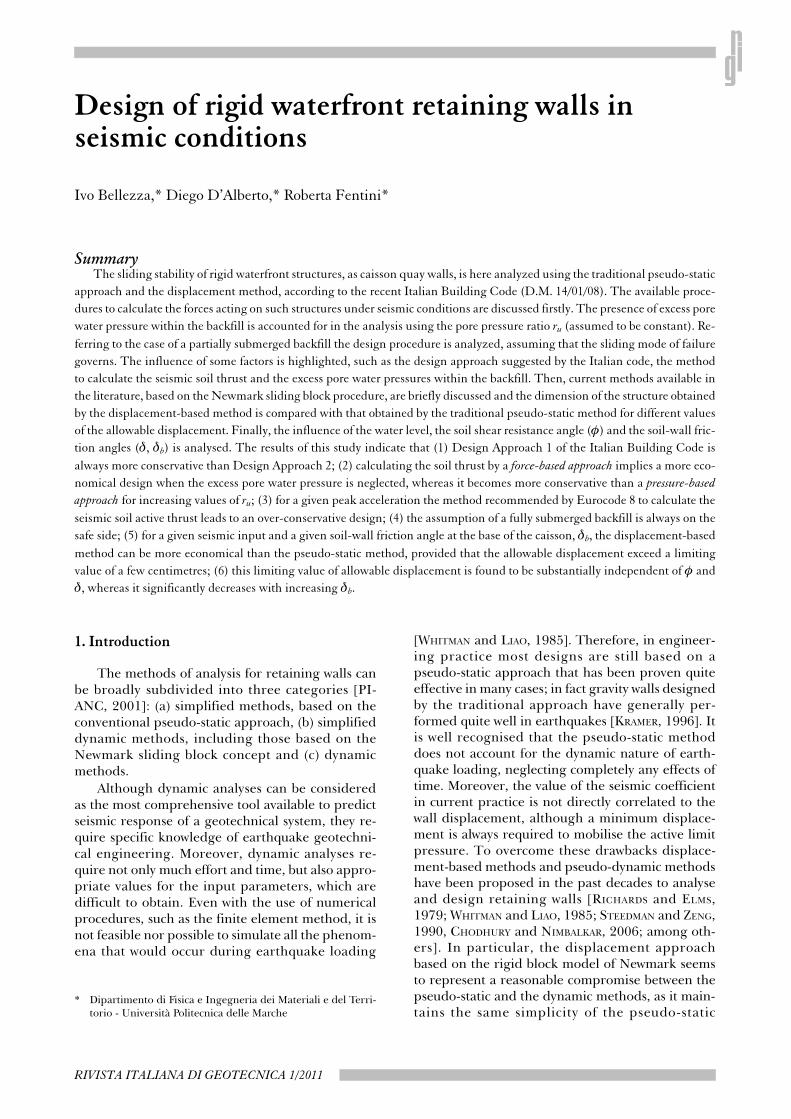
Fig. 1 shows a typical cross-section of a caissonquay wall with four cells, commonly filled with soil,concrete or water. A caisson with a simplified geom-etry is considered here, with width ‘B’, height ‘H’and average unit weight γc (Fig. 2); it retains backfillto its full height on the landward side and water to aheight ‘hS’ on the seaward side. The ground surface ofthe backfill is assumed to be horizontal; the water
level within the backfill (hL) is assumed be the sameas on the outer face of the wall.
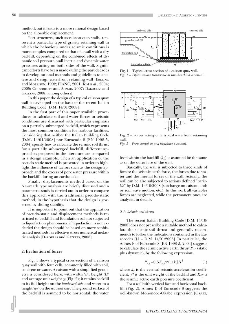
Basically, the wall is subjected to three kinds offorces: the seismic earth force, the forces due to wa-ter and the inertial forces of the wall. Actually, thewall can be also subjected to actions defined “varia-ble” by D.M. 14/10/2008 (surcharge on caisson and/or soil, wave motion, etc.). In this work all variablesforces are neglected, while the permanent ones areanalyzed in details.
2.1. Seismic soil thrust
The recent Italian Building Code [D.M. 14/10/2008] does not prescribe a suitable method to calcu-late the seismic soil thrust and generally recom-mends to follow the indications contained in the Eu-rocodes [§1 – D.M. 14/01/2008]. In particular, theAnnex E of Eurocode 8 [EN 1998-5, 2004] suggeststo calculate the seismic active earth thrust PAE (staticplus dynamic), by the following expression:
(1)
where kv is the vertical seismic acceleration coeffi-cient, γ * is the unit weight of the backfill and KAE isthe seismic active earth pressure coefficient.
For a wall with vertical face and horizontal back-fill (Fig. 2), Annex E of Eurocode 8 suggests thewell-known Mononobe-Okabe expression [OKABE,
Fig. 1 – Typical cross-section of a caisson quay wall.Fig. 1 – Tipica sezione trasversale di una banchina a cassoni.
Fig. 2 – Forces acting on a typical waterfront retainingwall.Fig. 2 – Forze agenti su una banchina a cassoni.
51DESIGN OF RIGID WATERFRONT RETAINING WALLS IN SEISMIC CONDITIONS
GENNAIO - MARZO 2011
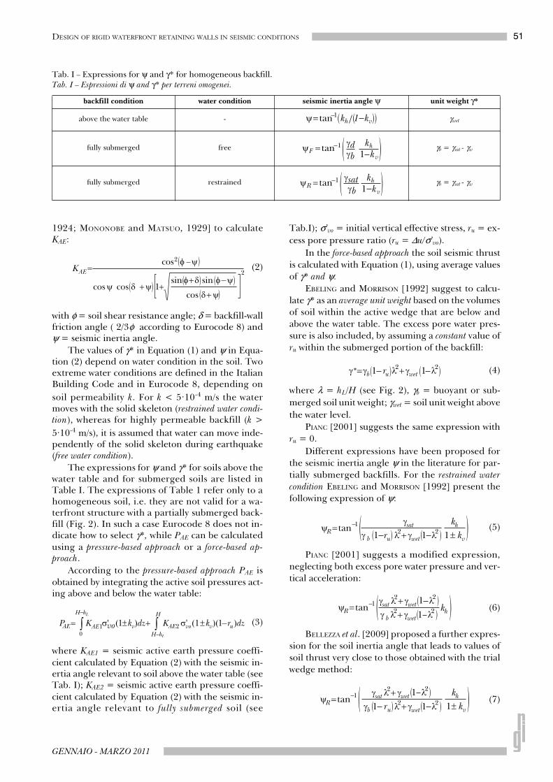
1924; MONONOBE and MATSUO, 1929] to calculateKAE:
(2)
with φ = soil shear resistance angle; δ = backfill-wallfriction angle ( 2/3φ according to Eurocode 8) andψ = seismic inertia angle.
The values of γ* in Equation (1) and ψ in Equa-tion (2) depend on water condition in the soil. Twoextreme water conditions are defined in the ItalianBuilding Code and in Eurocode 8, depending on
soil permeability k. For k < 5·10-4 m/s the watermoves with the solid skeleton (restrained water condi-tion), whereas for highly permeable backfill (k >
5·10-4 m/s), it is assumed that water can move inde-pendently of the solid skeleton during earthquake(free water condition).
The expressions for ψ and γ* for soils above thewater table and for submerged soils are listed inTable I. The expressions of Table 1 refer only to ahomogeneous soil, i.e. they are not valid for a wa-terfront structure with a partially submerged back-fill (Fig. 2). In such a case Eurocode 8 does not in-dicate how to select γ*, while PAE can be calculatedusing a pressure-based approach or a force-based ap-proach.
According to the pressure-based approach PAE isobtained by integrating the active soil pressures act-ing above and below the water table:
(3)
where KAE1 = seismic active earth pressure coeffi-cient calculated by Equation (2) with the seismic in-ertia angle relevant to soil above the water table (seeTab. I); KAE2 = seismic active earth pressure coeffi-cient calculated by Equation (2) with the seismic in-ertia angle relevant to fully submerged soil (see
Tab.I); σ’vo = initial vertical effective stress, ru = ex-
cess pore pressure ratio (ru = ∆u/σ’vo).
In the force-based approach the soil seismic thrustis calculated with Equation (1), using average valuesof γ* and ψ.
EBELING and MORRISON [1992] suggest to calcu-late γ* as an average unit weight based on the volumesof soil within the active wedge that are below andabove the water table. The excess pore water pres-sure is also included, by assuming a constant value ofru within the submerged portion of the backfill:
(4)
where λ = hL/H (see Fig. 2), γb = buoyant or sub-
merged soil unit weight; γwet = soil unit weight above
the water level.
PIANC [2001] suggests the same expression withru = 0.
Different expressions have been proposed forthe seismic inertia angle ψ in the literature for par-tially submerged backfills. For the restrained water
condition EBELING and MORRISON [1992] present thefollowing expression of ψ:
(5)
PIANC [2001] suggests a modified expression,neglecting both excess pore water pressure and ver-tical acceleration:
(6)
BELLEZZA et al. [2009] proposed a further expres-sion for the soil inertia angle that leads to values ofsoil thrust very close to those obtained with the trialwedge method:
(7)
Tab. I – Expressions for ψ and γ* for homogeneous backfill.Tab. I – Espressioni di ψ and γ* per terreni omogenei.
backfill condition water condition seismic inertia angle ψ unit weight γ*
above the water table - γwet
fully submerged free γb = γsat - γw
fully submerged restrained γb = γsat - γw
52 BELLEZZA - D’ALBERTO - FENTINI
RIVISTA ITALIANA DI GEOTECNICA
For the free water condition the soil horizontal in-ertia is assumed to be proportional only to the solidpart of the soil. In this case, Equations (5), (6) and(7) can be used by substituting the saturated unitweight γsat with the dry unit weight γd, and the hydro-dynamic force must be added [MATSUSAWA et al.,1985; EBELING and MORRISON, 1992; EN 1998-5,2004; PIANC, 2001].
The key aspect of the pseudo-static method isthe choice of seismic coefficients. The new ItalianBuilding Code [D.M. 14/01/2008] defines the hori-zontal seismic coefficient kh as a fraction βm of thepeak ground acceleration amax at the site:
(8)
where βm is a coefficient ranging between 0.18 and0.31 depending on the expected ground accelera-tion on rigid subsoil ag and on the subsoil classifica-tion [Tab. VII. 11.II - D.M. 14/01/2008].
In the absence of a specific local seismic analysis,the peak ground acceleration amax is related to ag bythe following expression [§7.11.6.2.1 – D.M. 14/01/2008]:
(9)
where SS is the stratigraphic amplification coeffi-cient variable between 0.9 and 1.8 [Tab. III.2.V -D.M. 14/01/2008], and ST is the topographic ampli-fication coefficient ranging between 1.0 and 1.4[Tab. III.2.VI - D.M. 14/01/2008]; for a maritimestructure ST is equal to unity.
2.2. Water thrust
The Italian Building Code does not indicate amethod to calculate the seismic water thrust. Ac-cording to Eurocode 8 “the hydrodynamic effect gener-ated by the presence of water in soil behind the wall and/orthe water in the outer face of the wall should be accountedfor”.
Eurocode 8 calculates the hydrodynamic forceat the seaward side, UdS, using Westergaard’s ap-proach [WESTERGAARD, 1933] valid for the case of avertical rigid dam retaining a semi-infinite reservoirof water that is excited by a harmonic motion of itsrigid base:
(10)
where khw is the horizontal seismic coefficient for thewater thrust.
For a waterfront retaining wall UdS is assumed toact in a direction opposite to the direction of the hy-drostatic force (UstS), and its point of application is
at 0.4hS above the base of the wall. For the free water
condition, Eurocode 8 and EBELING and MORRISON
[1992] suggest to consider the hydrodynamic waterthrust (obtained from Eq. (10) substituting hL to hS)also on the landward side acting in the same directionas the hydrostatic force (Fig. 2).
EBELING and MORRISON [1992] and PIANC[2001] assume for the seismic water thrust the samehorizontal seismic coefficient used for the soil (khw =kh). The Italian Building Code does not specify thisaspect, whereas Eurocode 8 explicitly states that inEquation (10) khw is always equal to amax/g, regardlessof the value of βm in Equation (8).
EBELING and MORRISON [1992] also consider anadditional water force due to the excess pore waterpressure induced by the cyclic load (Ush). For a par-tially submerged backfill, Ush is the resultant of atrapezoidal pressure distribution:
(11)
For the free water condition some studies [e.g.EBELING and MORRISON, 1992; CHOUDHURY and AH-MAD, 2007] conservatively consider both Ush andUdL. However it seems reasonable to include Ush
only for the restrained water condition when UdL isneglected. Finally, it is worthy of note that the pro-cedure followed in the free water condition is not to-tally consistent, as the effect of the increased porepressures due to the dynamic water pressure is ne-glected in the computation of the thrust due to soilskeleton [EBELING and MORRISON, 1992; PIANC,2001].
2.3. Inertial force of the wall
The inertial forces of the wall are proportionalto the total weight of the wall, W. Specifically, thehorizontal component, khW, is assumed to act in thesame direction as the seismic soil thrust PAE. Thevertical inertial force should be considered as actingupward or downward so as to produce the most unfa-vourable effect. In the rest of the paper the verticalinertial force is assumed upward (Fig. 2), which gen-erally represents the critical condition for the slid-ing mode of failure. The seismic coefficients kh andkv are the same used in the calculation of the soilthrust [e.g. EBELING and MORRISON, 1992; PIANC,2001]
3. Stability of caisson quay walls
A caisson quay wall is assimilated to a gravitywall and under seismic conditions the Italian Build-ing Code [§7.11.6.1 - D.M. 14/01/2008] requires toconsider the same limit states analyzed in static con-
53DESIGN OF RIGID WATERFRONT RETAINING WALLS IN SEISMIC CONDITIONS
GENNAIO - MARZO 2011
ditions, including overall stability, bearing capacityfailure, sliding failure and overturning. Moreoverevaluation of the liquefaction susceptibility is gener-ally required using well-established methods basedon in-situ tests (see Annex B of Eurocode 8).
If soils are found to be susceptible to liquefac-tion it is necessary to conduct the stability analysisfor tilting and bearing capacity as well as sliding un-der liquefied condition. In this paper it is assumedthat neither the backfill nor the foundation soil is af-fected by liquefaction phenomena or that a properremediation technique has been preventivelyadopted.
Similarly to the Eurocodes, all verifications mustuse the partial safety factors approach and for eachultimate limit state it must be verified that:
(12)
Assuming that the sliding limit state governs thedesign, Ed represents the design value of the overall
horizontal force whereas Rd is the design value of
the resistance against sliding along the base.
The resistance Rd depends on the resultant of all
vertical forces acting on the wall: total weight of cais-son quay wall (W), vertical inertial force (kvW), re-
sultant of pore water pressure acting on the base ofthe wall (Ub) and the vertical component of soil seis-
mic thrust (PAE,v).
Neglecting variable forces, it can be written:
(13)
where δdb is the design friction angle at the bottom
of the wall and γR is a partial safety factor.
The force Ub in Equation (13) depends on pore
water pressure distribution along the caisson quaywall base. In the simplest hypothesis the pore waterdistribution is assumed to vary linearly along thebase of the wall (Fig. 2), so that the resultant Ub can
be obtained on the basis of the values of water pres-sure acting at the two edges of the base [PIANC,2001]:
(14)
where ξ is a coefficient equal to 0 for the restrainedwater condition and equal to 1 for the free water condi-tion in the backfill.
According to EBELING and MORRISON [1992] andPIANC [2001], the effect of hydrodynamic pressurescan be neglected and Ub becomes:
(15)
This assumption is conservative for the restrainedwater condition and neutral for the free water condition,
provided that the water level is the same on bothsides of the wall (hS = hL).
It is important to note that the vertical force Ub
is always present in waterfront retaining walls andhas an unfavourable effect on sliding stability. Evenso, in some recent studies [CHOUDHURY and AHMAD,2007; 2008; AHMAD and CHOUDHURY, 2009] thisforce is erroneously neglected.
The action Ed is the sum of the horizontal compo-nent of the seismic soil thrust (PAE,h), the horizontalinertial force of the wall (khW), the static water thruston both sides of the wall, (UstL; UstS), the hydrody-namic thrust on the seaward side (UdS), the waterthrust due to excess pore water pressure generatedduring earthquake shaking (Ush) for the restrained wa-
ter condition or the hydrodynamic thrust on the land-ward side (UdL) for the free water condition.
In seismic conditions the design action is ob-tained combining the calculated values of actionswithout any amplification (i.e. all the partial coeffi-cients on actions, A1 and A2, are equal to the unity);neglecting eventual variable forces, the design ac-tion Ed for the sliding mode of failure can be ex-pressed as:
(16)
Equation (16) implicitly assumes that soil andwall inertial forces peak simultaneously and this as-sumption is conservative.
The verifications in seismic conditions must bemade considering the same combinations used instatic conditions, i.e. Combination 2 of Design Ap-proach 1 (A2+M2+R2) or Design Approach 2(A1+M1+R3); the values of the partial coefficientson the geotechnical parameters (γM) and on soil re-
sistance (γR) are listed in Table II and Table III, re-spectively.
An Explanatory Circular [CIRCOLARE 2 FEBBRAIO
2009, N. 617] specifies that the variations of soil
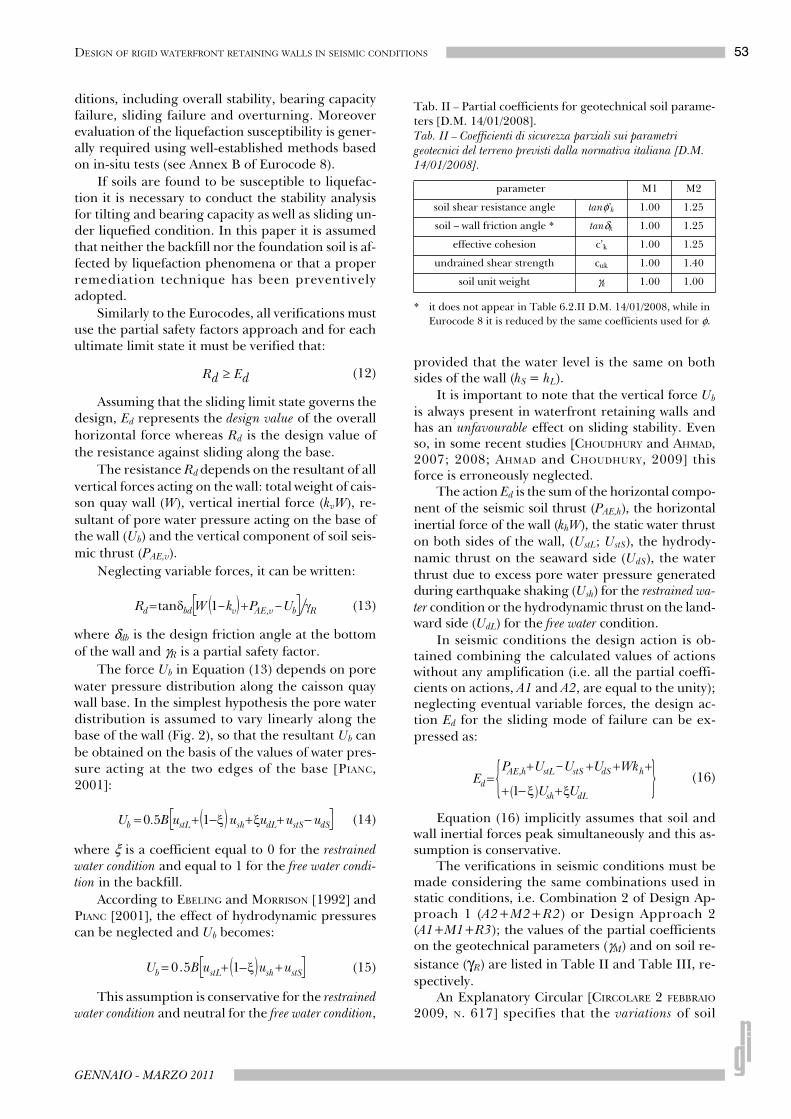
Tab. II – Partial coefficients for geotechnical soil parame-ters [D.M. 14/01/2008].Tab. II – Coefficienti di sicurezza parziali sui parametri geotecnici del terreno previsti dalla normativa italiana [D.M. 14/01/2008].
* it does not appear in Table 6.2.II D.M. 14/01/2008, while in
Eurocode 8 it is reduced by the same coefficients used for φ.
parameter M1 M2
soil shear resistance angle tanφ’k 1.00 1.25
soil – wall friction angle * tanδk 1.00 1.25
effective cohesion c’k 1.00 1.25
undrained shear strength cuk 1.00 1.40
soil unit weight γk 1.00 1.00
54 BELLEZZA - D’ALBERTO - FENTINI
RIVISTA ITALIANA DI GEOTECNICA
thrust induced by earthquakes have to be calculatedusing the M2 partial coefficients. Consequently, inseismic conditions the soil thrust PAE should be cal-culated starting from the static thrust PA(M1) evalu-ated with the characteristic value of the soil parame-ters (φk, δk,), as follows:
(17)
where ∆PAE(M2) is the difference between the seis-mic and the static soil thrust, both calculated usingthe partial factors of group M2 (see Tab. II).
4. Design of a caisson quay wall in seismic conditions by the pseudo-static approach
Substituting Equations (13) and (16) in Equa-tion (12) yields:
(18)
Taking into account Equation (15) and consid-ering that W =γcBH, the minimum base width B ofthe caisson quay wall can be obtained that satisfiesthe verification against the sliding mode of failure:
(19)
In the following paragraph Equation (19) isused in order to design a typical waterfront retain-ing wall, assuming that the sliding stability underseismic conditions governs the wall design.
The non-dimensional input parameters forbackfill and wall are: γc/γw = 2; γwet/γw = 1.8; γsat/γw
= 1.9; φk = 36°; δk = 24°; δbk = 31°; λ = 0.8; ru = 0.The water in the backfill is assumed to be in the re-strained condition (ξ = 0) and the hydrodynamicthrust UdS is calculated with a khw different fromthat of the seismic soil thrust (according to the in-dication of the Annex E of Eurocode 8). The aboveinput values can be considered representative of a
typical caisson quay wall with a medium densegranular backfill; the effect of φk, δk, δbk and λ willbe shown in Section 6.
4.1. Effect of the Design Approach
According to the provisions of the Italian BuildingCode [D.M. 14/01/2008], the seismic soil thrust can beestimated by three procedures. The first one followsDesign Approach 1 (DA1) and the soil thrust is entirelycalculated by the partial factors of group M2; in thesecond procedure the seismic soil thrust is calculatedby Equation (17); finally, in the third procedure, theverification against a sliding mode of failure is per-formed with DA2 using the characteristic values of thesoil parameters (M1). In all cases the soil thrust is cal-culated by the pressure-based approach (Eq.3).
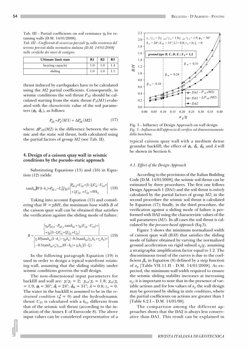
Figure 3 shows the minimum normalized widthof caisson quay wall (B/H) that satisfies the slidingmode of failure obtained by varying the normalizedground acceleration on rigid subsoil ag/g, assuminga stratigraphic amplification factor equal to 1.2. Thediscontinuous trend of the curves is due to the coef-ficient βm in Equation (8) defined by a step functionof ag [Table VII.11.II - D.M. 14/01/2008]. As ex-pected, the minimum wall width required to ensurethe seismic sliding stability increases at increasingag; it is important to note that in the presence of var-iable actions and for low values of ag the wall designmay be governed by sliding in static conditions, wherethe partial coefficients on actions are greater than 1[Table 6.2.I – D.M. 14/01/08].
The comparison among the different ap-proaches shows that the DA2 is always less conserv-ative than DA1. This result can be explained in
Tab. III – Partial coefficients on soil resistance γR for re-taining walls [D.M. 14/01/2008].Tab. III – Coefficienti di sicurezza parziali γR sulla resistenza del
terreno previsti dalla normativa italiana [D.M. 14/01/2008] nelle verifiche dei muri di sostegno.
Ultimate limit state R1 R2 R3
bearing capacity 1.0 1.0 1.4
sliding 1.0 1.0 1.1
Fig. 3 – Influence of Design Approach on wall design.Fig. 3 – Influenza dell’approccio di verifica sul dimensionamento della banchina.
55DESIGN OF RIGID WATERFRONT RETAINING WALLS IN SEISMIC CONDITIONS
GENNAIO - MARZO 2011
terms of equivalent global safety factor which isequal to 1.1 (= γR) in the DA2, whereas it is alwaysgreater than 1.25 in the DA1, as tanδbd = tanδbk/1.25. Therefore it the indication of the ExplanatoryCircular [CIRCOLARE 2 FEBBRAIO 2009, N. 617] thatconsiders Design Approach 1 “preferable” the forseismic sliding stability is justified. Of the two inter-pretations of DA1, the one suggested by the Explan-atory Circular [CIRCOLARE 2 FEBBRAIO 2009, N. 617]and represented by Equation (17) gives smaller val-ues of PAE, leading to lightly less onerous designs.Similar results to those shown in Figure 3 werefound by varying the values of input parameters inranges of practical interest [D’ALBERTO, 2010].
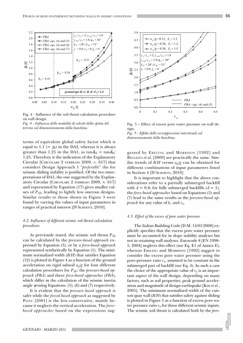
4.2. Influence of different seismic soil thrust calculation procedures
As previously stated, the seismic soil thrust PAE
can be calculated by the pressure-based approach ex-pressed by Equation (3), or by a force-based approachrepresented synthetically by Equation (1). The mini-mum normalized width (B/H) that satisfies Equation(12) is plotted in Figure 4 as a function of the groundacceleration on rigid subsoil ag/g for four differentcalculation procedures for PAE: the pressure-based ap-
proach (PBA) and three force-based approaches (FBA),which differ in the calculation of the seismic inertiaangle ψ using Equations. (5), (6) and (7) respectively.
It is evident that the pressure based approach issafer while the forced based approach as suggested byPIANC [2001] is the less conservative, mainly be-cause it neglects the vertical acceleration. The force-based approaches based on the expressions sug-
gested by EBELING and MORRISON [1992] andBELLEZZA et al. [2009] are practically the same. Sim-ilar trends of B/H versus ag/g can be obtained fordifferent combinations of input parameters listedin Section 4 [D’ALBERTO, 2010]
It is important to highlight that the above con-siderations refer to a partially submerged backfillwith λ = 0.8; for fully submerged backfills (λ = 1),the force-based approaches based on Equations (5) and(7) lead to the same results as the pressure-based ap-proach for any value of kv and ru.
4.3. Effect of the excess of pore water pressure
The Italian Building Code [D.M. 14/01/2008] ex-plicitly specifies that the excess pore water pressuremust be accounted for in slope stability analyses butnot in retaining wall analyses. Eurocode 8 [EN 1998-5, 2004] neglects this effect (see Eq. E1 of Annex E),whereas EBELING and MORRISON [1992] suggest toconsider the excess pore water pressure using thepore-pressure ratio ru, assumed to be constant in thesubmerged part of backfill (see Eq. 4). In such a casethe choice of the appropriate value of ru is an impor-tant aspect of the wall design, depending on manyfactors, such as soil properties, peak ground acceler-ation and magnitude of design earthquake [KIM et al.,2005]. The minimum normalized width of the cais-son quay wall (B/H) that satisfies safety against slidingis plotted in Figure 5 as a function of excess pore wa-ter pressure ratio ru for three different seismic inputs.The seismic soil thrust is calculated both by the pres-
Fig. 4 – Influence of the soil thrust calculation procedureon wall design.Fig. 4 – Influenza della modalità di calcolo della spinta del terreno sul dimensionamento della banchina.
Fig. 5 – Effect of excess pore water pressure on wall de-sign.Fig. 5 – Effetto delle sovrappressioni interstiziali sul dimensionamento della banchina.
56 BELLEZZA - D’ALBERTO - FENTINI
RIVISTA ITALIANA DI GEOTECNICA
sure-based approach (Eq. 3) and by the force-based ap-
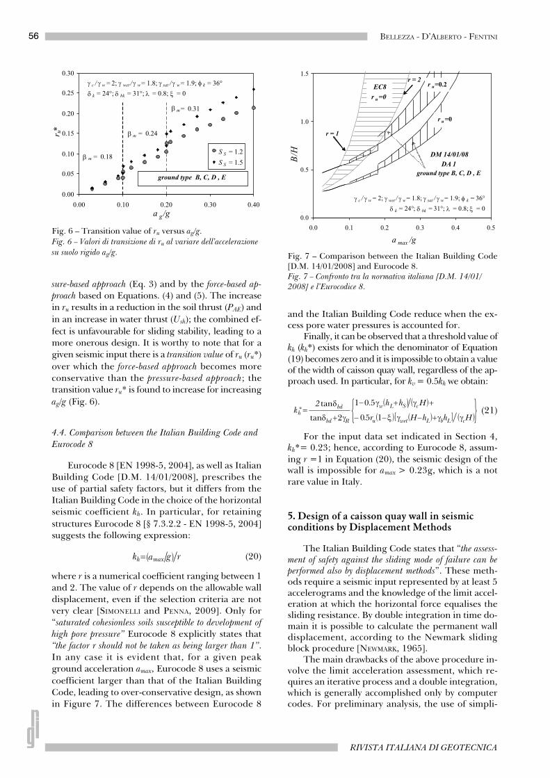
proach based on Equations. (4) and (5). The increasein ru results in a reduction in the soil thrust (PAE) and
in an increase in water thrust (Ush); the combined ef-
fect is unfavourable for sliding stability, leading to amore onerous design. It is worthy to note that for agiven seismic input there is a transition value of ru (ru*)
over which the force-based approach becomes moreconservative than the pressure-based approach; thetransition value ru* is found to increase for increasing
ag/g (Fig. 6).
4.4. Comparison between the Italian Building Code and
Eurocode 8
Eurocode 8 [EN 1998-5, 2004], as well as ItalianBuilding Code [D.M. 14/01/2008], prescribes theuse of partial safety factors, but it differs from theItalian Building Code in the choice of the horizontalseismic coefficient kh. In particular, for retaining
structures Eurocode 8 [§ 7.3.2.2 - EN 1998-5, 2004]suggests the following expression:
(20)
where r is a numerical coefficient ranging between 1and 2. The value of r depends on the allowable walldisplacement, even if the selection criteria are notvery clear [SIMONELLI and PENNA, 2009]. Only for“saturated cohesionless soils susceptible to development of
high pore pressure” Eurocode 8 explicitly states that“the factor r should not be taken as being larger than 1”.In any case it is evident that, for a given peakground acceleration amax, Eurocode 8 uses a seismic
coefficient larger than that of the Italian BuildingCode, leading to over-conservative design, as shownin Figure 7. The differences between Eurocode 8
and the Italian Building Code reduce when the ex-cess pore water pressures is accounted for.
Finally, it can be observed that a threshold value ofkh (kh*) exists for which the denominator of Equation(19) becomes zero and it is impossible to obtain a valueof the width of caisson quay wall, regardless of the ap-proach used. In particular, for kv = 0.5kh we obtain:
(21)
For the input data set indicated in Section 4,kh*= 0.23; hence, according to Eurocode 8, assum-ing r =1 in Equation (20), the seismic design of thewall is impossible for amax > 0.23g, which is a notrare value in Italy.
5. Design of a caisson quay wall in seismic conditions by Displacement Methods
The Italian Building Code states that “the assess-ment of safety against the sliding mode of failure can beperformed also by displacement methods”. These meth-ods require a seismic input represented by at least 5accelerograms and the knowledge of the limit accel-eration at which the horizontal force equalises thesliding resistance. By double integration in time do-main it is possible to calculate the permanent walldisplacement, according to the Newmark slidingblock procedure [NEWMARK, 1965].
The main drawbacks of the above procedure in-volve the limit acceleration assessment, which re-quires an iterative process and a double integration,which is generally accomplished only by computercodes. For preliminary analysis, the use of simpli-
Fig. 6 – Transition value of ru versus ag/g.
Fig. 6 – Valori di transizione di ru al variare dell’accelerazione
su suolo rigido ag/g. Fig. 7 – Comparison between the Italian Building Code[D.M. 14/01/2008] and Eurocode 8.Fig. 7 – Confronto tra la normativa italiana [D.M. 14/01/2008] e l’Eurocodice 8.
57DESIGN OF RIGID WATERFRONT RETAINING WALLS IN SEISMIC CONDITIONS
GENNAIO - MARZO 2011
fied methods can be convenient, in which the limitacceleration, alim, and the wall displacement, d, are
correlated by empirical expressions to simple pa-rameters of the design earthquake, such as the max-imum acceleration, amax, and the maximum velocity,vmax.
The pioneering displacement-based method forretaining walls has been proposed by RICHARDS andELMS [1979] who suggested the following expres-sion:
(22)
Afterwards, WHITMAN and LIAO [1985] refinedthe method by statistical analyses in order to evalu-ate the effect of some simplifying assumptions of theRichards and Elms procedure.
In particular, the deformability of the backfill,the tilting mechanisms and the vertical accelerationare neglected by RICHARDS and ELMS [1979] and iftheir effect is considered the permanent displace-ment is found to increase [NADIM, 1980; SIDDARTHAN
et al., 1992; WHITMAN and LIAO, 1985]. On the con-trary, kinematic constraints lead to conclude that ifthe backfill wedge and the wall are treated as sepa-rate blocks [ZARRABI -KASHANI, 1979], the displace-ments are systematically smaller than those pre-dicted by the single-block model (wedge + wall) ofRICHARDS and ELMS [1979]. Considering the com-bined effects of these sources of uncertainties, WHIT-MAN and LIAO [1985] suggested to insert a model fac-tor M (with mean value M
–= 3.5) to correct the dis-
placement obtained by a simplified analysis basedon the rigid block model of Newmark.
WHITMAN and LIAO [1985] introduced a furthercorrective parameter, F, to take into account the in-fluence of other factors on the seismic behaviour ofthe wall-backfill system, e.g. the orientation of thewall with respect the direction of the ground mo-tion. WHITMAN and LIAO [1985] proposed F = 2.5and F = 4 if the displacement dp corresponds to aprobability of not exceeding of 90% and 95%, re-spectively.
Finally, the complete expression summarizingthe WHITMAN and LIAO [1985] method is given by:
(23)
Recently, on the basis of a collection of 196records from 46 Italian earthquakes with magnituderanging from 4 and 6.3, MADIAI [2009] proposed thefollowing alternative expressions:
(24)
(25)
where A2a and A2b are numerical coefficients de-pending on the confidence level (CL); in particularA2a = 49, A2b = 3.89 for CL = 50% and A2a = 95, A2b
= 7.15 for CL = 90%.Different expressions have been proposed also
by RAMPELLO and CALLISTO [2008] and by RAMPELLO
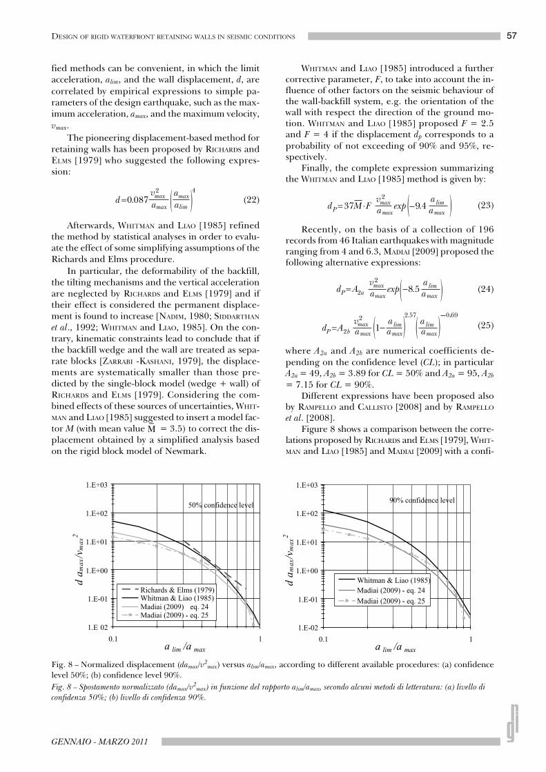
et al. [2008].Figure 8 shows a comparison between the corre-
lations proposed by RICHARDS and ELMS [1979], WHIT-MAN and LIAO [1985] and MADIAI [2009] with a confi-
Fig. 8 – Normalized displacement (damax/v2max) versus alim/amax, according to different available procedures: (a) confidence
level 50%; (b) confidence level 90%.
Fig. 8 – Spostamento normalizzato (damax/v2
max) in funzione del rapporto alim/amax, secondo alcuni metodi di letteratura: (a) livello di
confidenza 50%; (b) livello di confidenza 90%.
58 BELLEZZA - D’ALBERTO - FENTINI
RIVISTA ITALIANA DI GEOTECNICA
dence level of 50% and 90% in terms of the normal-
ized displacement dP·amax/v2max versus alim/amax.
When the design of a waterfront wall is based ona displacement method the Equations (23) - (25) canbe used to obtain the limit acceleration alim, as afunction of the selected allowable displacement dP
and the seismic parameters amax and vmax.
Rearranging Equations (23) and (24) yields:
(26)
(27)
Equation (25) must be solved numerically to ob-tain alim.
Once the limit acceleration is known, the valueof the horizontal seismic coefficient kh,lim (= alim/g) isused to calculate the seismic active thrust PAE, usingthe characteristic value of soil parameters (M1) andneglecting the vertical acceleration (kv = 0).
By imposing the limit horizontal equilibriumcondition of the wall (i.e. Rd = Ed), the minimumwall width can be obtained by Equation (19) withγR = 1 (see Tab. IV).
If the Whitman & Liao correlation is used, it isnot necessary to apply any further safety factor, asthe uncertainties are included in the model factorM. Conversely, other methods that do not explicitlyinclude the above sources of uncertainties require asafety factor varying in the range 1.1-1.2, accordingto the indications of WHITMAN and LIAO [1985].
All the empirical correlations were originallydeveloped for a dry backfill, i.e. the effect of waterforces on the seismic displacement was not consid-ered. The displacement of a waterfront retainingwall is expected to also depend on the action due towater. EBELING and MORRISON [1992] use the samehorizontal seismic coefficient (kh,lim = alim/g) for thehydrodynamic force. In the absence of studies sup-
porting this assumption, it seems more reasonable(and conservative) to calculate Ud as a function ofthe maximum acceleration amax, according to theEurocode 8 recommendation for the pseudo-staticmethod.
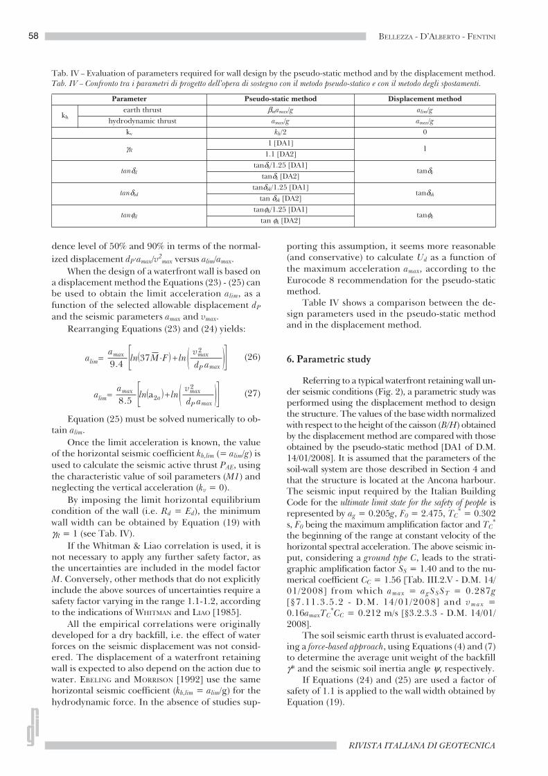
Table IV shows a comparison between the de-sign parameters used in the pseudo-static methodand in the displacement method.
6. Parametric study
Referring to a typical waterfront retaining wall un-der seismic conditions (Fig. 2), a parametric study wasperformed using the displacement method to designthe structure. The values of the base width normalizedwith respect to the height of the caisson (B/H) obtainedby the displacement method are compared with thoseobtained by the pseudo-static method [DA1 of D.M.14/01/2008]. It is assumed that the parameters of thesoil-wall system are those described in Section 4 andthat the structure is located at the Ancona harbour.The seismic input required by the Italian BuildingCode for the ultimate limit state for the safety of people isrepresented by ag = 0.205g, F0 = 2.475, TC
* = 0.302s, F0 being the maximum amplification factor and TC
*
the beginning of the range at constant velocity of thehorizontal spectral acceleration. The above seismic in-put, considering a ground type C, leads to the strati-graphic amplification factor SS = 1.40 and to the nu-merical coefficient CC = 1.56 [Tab. III.2.V - D.M. 14/01/2008] from which amax = agSSST = 0.287g[§7.11.3.5.2 - D.M. 14/01/2008] and vmax =0.16amaxTC
*CC = 0.212 m/s [§3.2.3.3 - D.M. 14/01/2008].
The soil seismic earth thrust is evaluated accord-ing a force-based approach, using Equations (4) and (7)to determine the average unit weight of the backfillγ* and the seismic soil inertia angle ψ, respectively.
If Equations (24) and (25) are used a factor ofsafety of 1.1 is applied to the wall width obtained byEquation (19).
Tab. IV – Evaluation of parameters required for wall design by the pseudo-static method and by the displacement method.Tab. IV – Confronto tra i parametri di progetto dell’opera di sostegno con il metodo pseudo-statico e con il metodo degli spostamenti.
Parameter Pseudo-static method Displacement method
kh
earth thrust βmamax/g alim/g
hydrodynamic thrust amax/g amax/g
kv kh/2 0
γR
1 [DA1]1
1.1 [DA2]
tanδd
tanδk/1.25 [DA1]tanδk
tanδk [DA2]
tanδbd
tanδbk/1.25 [DA1]tanδbk
tan δbk [DA2]
tanφd
tanφk/1.25 [DA1]tanφk
tan φk [DA2]
59DESIGN OF RIGID WATERFRONT RETAINING WALLS IN SEISMIC CONDITIONS
GENNAIO - MARZO 2011
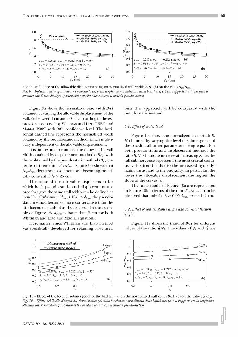
Figure 9a shows the normalized base width B/H
obtained by varying the allowable displacement of the
wall, dP, between 1 cm and 30 cm, according to the ex-
pressions proposed by WHITMAN and LIAO [1985] and
MADIAI [2009] with 90% confidence level. The hori-
zontal dashed line represents the normalised width
obtained by the pseudo-static method, which is obvi-
ously independent of the allowable displacement.
It is interesting to compare the values of the wall
width obtained by displacement methods (Bdis) with
those obtained by the pseudo-static method (Bpse), in
terms of their ratio Bdis/Bpse. Figure 9b shows that
Bdis/Bpse decreases as dP increases, becoming practi-
cally constant if dP > 25 cm.
The value of the allowable displacement for
which both pseudo-static and displacement ap-
proaches give the same wall width can be defined as
transition displacement (dtrans). If dP > dtrans the pseudo-
static method becomes more conservative than the
displacement method and vice versa. In the exam-
ple of Figure 9b, dtrans is lower than 2 cm for both
Whitman and Liao and Madiai equations.
Hereinafter, since Whitman and Liao method
was specifically developed for retaining structures,
only this approach will be compared with thepseudo-static method.
6.1. Effect of water level
Figure 10a shows the normalized base width B/H obtained by varying the level of submergence ofthe backfill, all other parameters being equal. Forboth pseudo-static and displacement methods theratio B/H is found to increase at increasing λ, i.e. thefull submergence represents the most critical condi-tion; this trend is due to the increased hydrody-namic thrust and to the buoyancy. In particular, thelower the allowable displacement the higher theslope of the curves is.
The same results of Figure 10a are representedin Figure 10b in terms of the ratio Bdis/Bpse. It can be
observed that only for λ > 0.95 dtrans exceeds 2 cm.
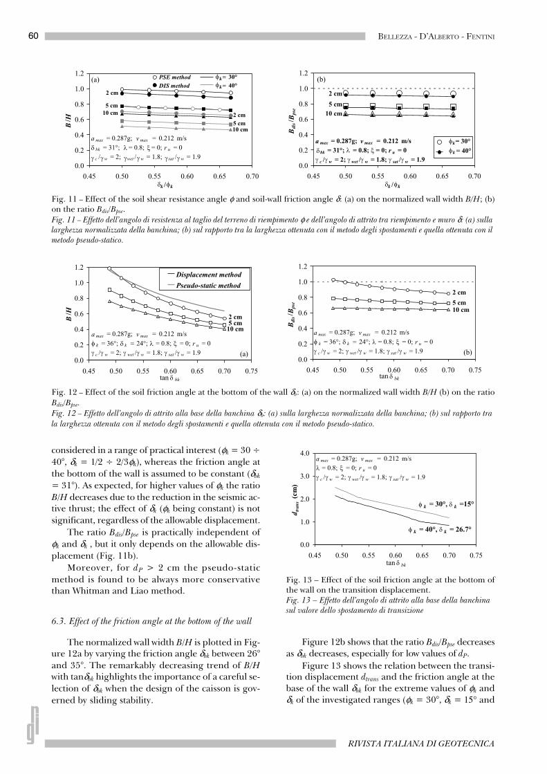
6.2. Effect of soil resistance angle and soil-wall friction
angle
Figure 11a shows the trend of B/H for differentvalues of the ratio δk/φk. The values of φk and δk are
Fig. 9 – Influence of the allowable displacement (a) on normalized wall width B/H; (b) on the ratio Bdis/Bpse.Fig. 9 – Influenza dello spostamento ammissibile (a) sulla larghezza normalizzata della banchina; (b) sul rapporto tra la larghezza ottenuta con il metodo degli spostamenti e quella ottenuta con il metodo pseudo-statico.
Fig. 10 – Effect of the level of submergence of the backfill: (a) on the normalized wall width B/H; (b) on the ratio Bdis/Bpse.Fig. 10 – Effetto del livello d’acqua del riempimento: (a) sulla larghezza normalizzata della banchina; (b) sul rapporto tra la larghezzaottenuta con il metodo degli spostamenti e quella ottenuta con il metodo pseudo-statico.
60 BELLEZZA - D’ALBERTO - FENTINI
RIVISTA ITALIANA DI GEOTECNICA
considered in a range of practical interest (φk = 30 ÷
40°, δk = 1/2 ÷ 2/3φk), whereas the friction angle at
the bottom of the wall is assumed to be constant (δbk
= 31°). As expected, for higher values of φk the ratio
B/H decreases due to the reduction in the seismic ac-tive thrust; the effect of δk (φk being constant) is not
significant, regardless of the allowable displacement.
The ratio Bdis/Bpse is practically independent of
φk and δk , but it only depends on the allowable dis-
placement (Fig. 11b).
Moreover, for dP > 2 cm the pseudo-static
method is found to be always more conservativethan Whitman and Liao method.
6.3. Effect of the friction angle at the bottom of the wall
The normalized wall width B/H is plotted in Fig-ure 12a by varying the friction angle δbk between 26°
and 35°. The remarkably decreasing trend of B/Hwith tanδbk highlights the importance of a careful se-
lection of δbk when the design of the caisson is gov-
erned by sliding stability.
Figure 12b shows that the ratio Bdis/Bpse decreasesas δbk decreases, especially for low values of dP.
Figure 13 shows the relation between the transi-tion displacement dtrans and the friction angle at thebase of the wall δbk for the extreme values of φk andδk of the investigated ranges (φk = 30°, δk = 15° and
Fig. 11 – Effect of the soil shear resistance angle φ and soil-wall friction angle δ: (a) on the normalized wall width B/H; (b)on the ratio Bdis/Bpse.Fig. 11 – Effetto dell’angolo di resistenza al taglio del terreno di riempimento φ e dell’angolo di attrito tra riempimento e muro δ: (a) sulla larghezza normalizzata della banchina; (b) sul rapporto tra la larghezza ottenuta con il metodo degli spostamenti e quella ottenuta con il metodo pseudo-statico.
Fig. 12 – Effect of the soil friction angle at the bottom of the wall δb: (a) on the normalized wall width B/H (b) on the ratioBdis/Bpse.
Fig. 12 – Effetto dell’angolo di attrito alla base della banchina δb: (a) sulla larghezza normalizzata della banchina; (b) sul rapporto tra
la larghezza ottenuta con il metodo degli spostamenti e quella ottenuta con il metodo pseudo-statico.
Fig. 13 – Effect of the soil friction angle at the bottom ofthe wall on the transition displacement.Fig. 13 – Effetto dell’angolo di attrito alla base della banchina sul valore dello spostamento di transizione
61DESIGN OF RIGID WATERFRONT RETAINING WALLS IN SEISMIC CONDITIONS
GENNAIO - MARZO 2011
φk = 40°, δk = 26.7°). It is evident that dtrans isstrongly influenced by δbk, but it changes very mar-ginally with the variation of φk and δk, as the valuesobtained for the two combinations do not differmore than 0.5 cm.
7. Final Remarks
Available procedures to estimate seismic forcesacting on a caisson quay wall are analyzed and dis-cussed for partially submerged backfills.
In the hypothesis that the backfill and founda-tion soil are not affected by liquefaction phenomenaand that sliding stability governs the design, theminimum width of the wall has been determined byboth pseudo-static and displacement methods ac-cording to the recent Italian Building Code [D.M.14/01/2008 and CIRCOLARE 2 FEBBRAIO 2009, N. 617].On the basis of the results obtained for a typical setof input parameters the following conclusions canbe drawn:
– under seismic conditions, Design Approach 1 isfound to be always more conservative than De-sign Approach 2;
– in the absence of excess pore water pressure inthe backfill (ru = 0) the seismic active soil thrustcalculated by a force-based approach results in aless conservative design than using the pressure-based approach; this trend also holds for smallvalues of ru, but a threshold value of ru existsover which the force-based approach becomesmore conservative;
– the development of positive excess-pore waterpressures within the backfill always leads to amore onerous design;
– the application of the pseudo-static method withvalues of the seismic coefficient kh suggested byEurocode 8 results in over-conservative designswith respect to the Italian Building Code;
– the sliding stability decreases for increasing wa-ter level within the backfill; i.e. the assumptionof a fully submerged backfill is always on the safeside;
– the displacement-based approach results in a moreeconomical design than the pseudo-static method,provided that the allowable displacement begreater than the transition displacement foundto be few centimeters;
– the value of the transition displacement stronglydepends on the friction angle at the base of thewall (δb), whereas the influence of φ and δ of thebackfill is small in the range of practical interest.
It is worthy to highlight that the displacementmethods based on Newmark sliding block approachare recommended only for preliminary analyses, es-pecially for waterfront retaining walls, as the empir-
ical expressions available in the literature do notconsider the effect of hydrodynamic forces. Forstructures of high performance grade the use ofmore sophisticated methods, i.e. full dynamic anal-ysis, is recommended.
References
AHMAD S.M., CHOUDHURY D. (2009) - Seismic designfactor for sliding of waterfront retaining wall. Pro-ceeding of the Institution of Civil Engineers, Ge-otechnical Engineering, 162, pp. 269-276.
BELLEZZA I., FENTINI R., FRATALOCCHI E., PASQUALINI
E. (2009) - Stability of waterfront retaining walls inseismic conditions. Proceedings ICSMGE, Alexan-dria, Egypt. vol. II, pp. 1405-1408. Ed. IOS PressBV Amsterdam. ISBN 978-1-60750-031-5.
CHOUDHURY D., AHMAD S.M. (2007) - Stability of water-front retaining wall subjected to pseudo-static earth-quake forces. Ocean Engineering 34, pp. 1947-1957.
CHOUDHURY D., AHMAD S.M. (2008) - Stability of water-front retaining wall subjected to pseudo-dynamic earth-quake forces. Journal of Waterway, Port, Coastal,Ocean Engineering, ASCE, 134, pp. 252-262.
CHOUDHURY D., NIMBALKAR S.S. (2006) - Pseudo-dy-namic approach of seismic active earth pressure behindretaining wall. Geotechnical and Geological Engi-neering, 24, pp. 1103-1113.
CIRCOLARE 2 FEBBRAIO 2009 N° 617 (2009) - Istruzioniper l’applicazione delle “Nuove norme tecniche per lecostruzioni” di cui al D.M. 14 gennaio 2008. G. U.del 26 febbraio 2009, n. 47, Supplemento ordi-nario n. 27.
D. M. 14/01/2008 (2008) - Decreto del Ministerodelle Infrastrutture Nuove norme tecniche per le cos-truzioni. G.U. del 4 febbraio 2008, n. 29.
D’ALBERTO D. (2010) - Contributi al dimensionamentodi opere di sostegno in condizioni sismiche. PhD The-sis, Università Politecnica delle Marche.
DAKOULAS P., GAZETAS G. (2008) - Insight into seismicearth and water pressures against caisson quay walls.Géotechnique 53, n. 2, pp. 95-111.
EBELING R.M., MORRISON E.E. (1992) - The seismic de-sign of waterfront retaining structures. Technical re-port ITL-92-11. Washington, DC. US ArmyCorps of Engineers.
EN 1998-5 (2004) - Eurocode 8: Design of structures forearthquake resistance. Part 5: Foundations, retainingstructures and geotechnical aspects. CEN EuropeanCommittee for Standardization, Bruxelles, Bel-gium.
KIM S.R., JANG I.S., CHUNG C.K., KIM M.M. (2005) -Evaluation of seismic displacements of quay walls. SoilDynamics and Earthquake Engineering, 25, pp.451-459.
62 BELLEZZA - D’ALBERTO - FENTINI
RIVISTA ITALIANA DI GEOTECNICA
KIM S.R., KWON O.S., KIM M.M. (2004) - Evaluation
of force components acting on gravity type quay walls
during earthquakes. Soil Dynamics and EarthquakeEngineering, 24, pp. 853-866.
KRAMER S.L. (1996) - Geotechnical Earthquake
Engineering. Pearson Education Inc. New Jersey.
MADIAI C. (2009) - Correlazioni tra parametri del moto
sismico e spostamenti attesi del blocco di Newmark. Ital-ian Geotechnical Journal, 43, n.1, pp. 23-43.
MATSUSAWA H., ISHIBASHI I., KAWAMURA M. (1985) -Dynamic soil and water pressures on submerged soils.Journal of the Geotechnical Engineering Divi-sion. ASCE, vol. CV, n. 4, pp. 449-464.
MONONOBE N., MATSUO H. (1929) - On the determination
of earth pressures during earthquakes. Proc of theThird World Conf. on Earthquake Engineeringvol. I, pp. 130-140.
NADIM F. (1980) - Tilting and sliding of gravity retain-
ing walls. MS Thesis. Department Civil Engineer-ing, MIT Cambridge. Massachusetts.
NEWMARK N.M. (1965) - Effect of earthquake on dams
and embankments. Géotechnique, n. 15, pp. 139-160.
OKABE S. (1924) - General theory of earth pressure and
seismic stability of retaining wall and dam. Journ. ofthe Japanese Society of Civil Engineers, 10, n. 5,pp. 1277-1323.
PIANC (2001) - Seismic design guidelines for port struc-
tures. A.A. Balkema Publishers.
RAMPELLO S. AND CALLISTO L. (2008) - Stabilità dei pen-
dii in condizioni sismiche. Proc. XII Conference onMechanics and Engineering of Rocks (MIR),Torino, Pàtron Editore, pp. 241-271.
RAMPELLO S., CALLISTO L., FARGNOLI P. (2008) - Eval-
uation of seismic coefficients for slope stability analysis
using a displacement-based approach. Panel paper.Proc. of the Seismic Engineering InternationalConference commemorating the 1908 Messinaand Reggio Calabria Earthquake (Mercea).
RICHARDS R., ELMS D. (1979) - Seismic behaviour of
gravity retaining walls. Journal of the GeotechnicalEngineering Division ASCE, vol. CV, n. 4, pp.449-464.
SIDDHARTHAN R., ARA S., NORRIS G.M. (1992) - Simple
rigid plastic model for seismic tilting of rigid walls.Journal of Structural Engineering ASCE. vol.CXVIII, n. 2, pp. 469-487.
SIMONELLI A.L., PENNA A. (2009) - Performance-based
design of gravity retaining walls under seismic actions.Proc. Workshop on ‘Eurocode 8: Perspectivesfrom the Italian Standpoint’, pp. 277-279, E.Cosenza (Ed.) Doppiavoce, Napoli, Italy.
STEEDMAN R.S., ZENG X. (1990) - The influence of phase
on the calculation of pseudo-static earth pressure on re-
taining wall. Géotechnique, 40, n.1, pp. 103-112.
WESTERGAARD H.M. (1933) - Water pressures on dams
during earthquakes. Trans. ASCE 98, pp. 418-433.
WHITMAN R.V., LIAO S. (1985) - Seismic design of re-
taining walls. Miscellaneous paper GL-85-1, USArmy Eng. Waterways Experiment Station, Vicks-burg, MS.
ZARRABI-KASHANI (1979) - Sliding of gravity retaining
wall during earthquakes considering vertical accelera-
tion and changing inclination of failure surface. MSThesis. Department Civil Engineering, MITCambridge. Massachusetts.
Dimensionamento di una banchina a
cassoni in condizioni sismiche
SommarioViene esaminato il progetto di una banchina a cassoni
utilizzando sia il metodo pseudo-statico sia il metodo degli
spostamenti alla luce della recente normativa italiana,
assumendo che la verifica a scorrimento governi il
dimensionamento. Dapprima sono discusse le procedure di
calcolo della forze coinvolte nell’equilibrio della struttura nel caso
frequente di riempimento parzialmente sommerso, poi viene
evidenziata l’influenza di alcuni fattori, quali l’approccio di
verifica prescritto dal D.M. 14/01/2008, la modalità di calcolo
della spinta del terreno e la presenza di eventuali sovrappressioni
interstiziali sviluppate nel terrapieno a seguito della
sollecitazione ciclica, confrontando infine la recente normativa
italiana con l’Eurocodice 8. Dopo una breve panoramica dei
metodi degli spostamenti disponibili in letteratura, viene proposto
un esempio di dimensionamento basato sia sul metodo degli
spostamenti sia sul tradizionale metodo pseudo-statico,
valutando l’effetto sul dimensionamento della banchina di alcuni
parametri quali il livello di sommersione, l’angolo di resistenza
al taglio del terreno di riempimento e l’angolo di attrito tra
terreno e struttura. I risultati ottenuti indicano che (1)
l’Approccio 1 suggerito dal D.M. 14/01/08 è sempre più
cautelativo dell’Approccio 2; (2) trascurando le sovrappressioni
nel terrapieno, se la spinta dinamica del terreno è calcolata con
un approccio basato sul cuneo di Coulomb il dimensionamento è
meno oneroso rispetto a quando la spinta è calcolata secondo un
approccio basato sulle pressioni; (3) per un assegnato valore
dell’accelerazione di picco l’uso dei coefficienti sismici suggeriti
dall’Eurocodice 8 porta a dimensionamenti ultra-conservativi;
(4) il metodo degli spostamenti può permettere un
dimensionamento meno oneroso rispetto al metodo pseudo-statico,
a patto che lo spostamento ammissibile per l’opera sia inferiore ad
un valore limite stimato in pochi centimetri; (5) il valore di
questo spostamento limite dipende significativamente dal valore
dell’angolo di attrito δb tra struttura e terreno di base, mentre è
praticamente indipendente dal valore dell’angolo di resistenza al
taglio del riempimento φ e dell’angolo di attrito δ tra terreno di
riempimento e opera di sostegno, variabili nell’intervallo di
interesse di pratico.