Embed Size (px)
DESCRIPTION
project
Citation preview

DESIGN OF ROLLONG STOCK MAINTANANCE SHED ROOF TRUSS
HARSHAVARDHAN.K.P
KRISHNAN.C
UVARAJ.D

TRUSS
In architecture and structural engineering, a truss is a structure comprising one or more triangular units constructed with straight members whose ends are connected at joints referred to as nodes. External forces and reactions to those forces are considered to act only at the nodes and result in forces in the members which are Either tensile or compressive forces. Moments (torques) are explicitly excluded because, and only because, all the joints in a truss are treated as revolutes.

GENERAL
• Roof of rolling stock is proposed with steel trusses covered with metallic sheets.
• There are three types of trusses based on location
ADVANTAGES
• Fully engineered and ease of construction• Reduced site waste, loss and pilferage of materials.• Space saving on site, with no need for timber storage or
carpentry areas.• Material savings: trusses can use up to 40% less timber than a
traditionally built roof.
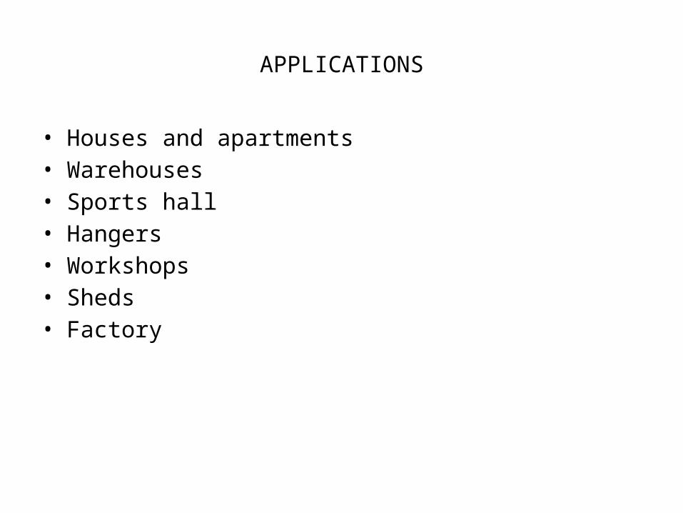
APPLICATIONS
• Houses and apartments • Warehouses• Sports hall• Hangers• Workshops• Sheds • Factory
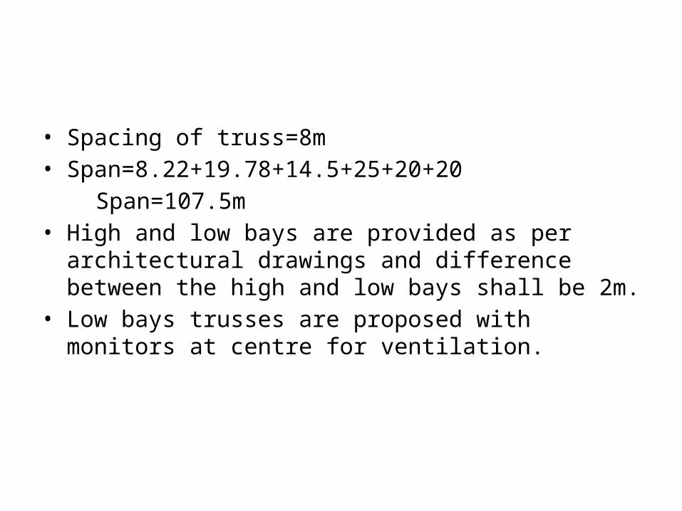
• Spacing of truss=8m• Span=8.22+19.78+14.5+25+20+20
Span=107.5m• High and low bays are provided as per architectural drawings
and difference between the high and low bays shall be 2m.• Low bays trusses are proposed with monitors at centre for
ventilation.

• The Rafter and Tie Members have been adequately braced laterally thus preventing out-of-plane buckling.
• The compression member have been designed against buckling in and out of the truss.
• All members of the truss are proposed as Double Angles Back-to-Back.

OBJECTIVE• To design maintenance shed 107.5m X 192m height 20m, roof
slope 1 in 10.
LOCATION • Koyambedu, Chennai
DIMENSIONS• Plan dimensions=107.5 x 192m• Height at centre = 20m• Roof angle = 5º• Slope = 1 in 10• Purlin spacing = 1.325m

LOAD CONSIDERATIONS
Dead Load
Live Load
Wind Load
METHODOLOGY
The structure is designed by Limit State method of Design. IS 800-2007 is followed for limit state method. Structural components to be designed are roof truss, connections and RCC columns to support the truss.
CODE BOOKS
IS 875
IS 800-2007

DESIGN OF ROOF TRUSS

LOAD CALCULATIONS
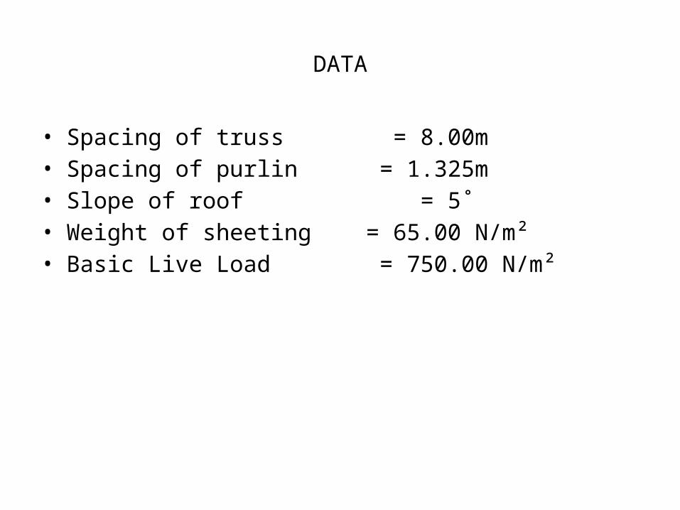
DATA
• Spacing of truss = 8.00m• Spacing of purlin = 1.325m• Slope of roof = 5˚• Weight of sheeting = 65.00 N/m²• Basic Live Load = 750.00 N/m²
LOADS
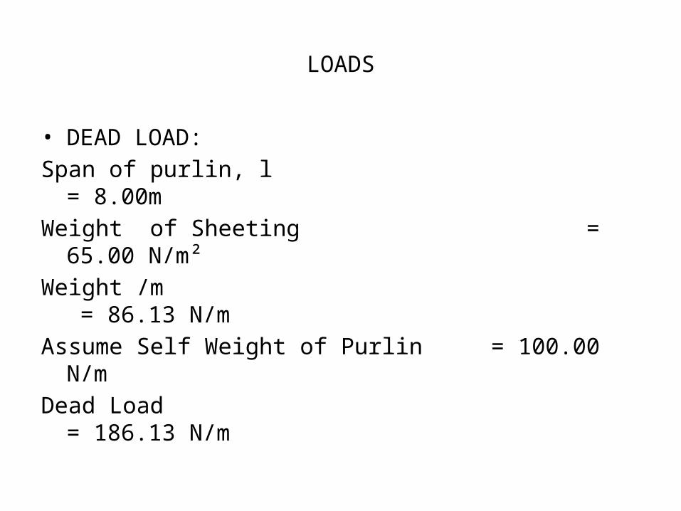
• DEAD LOAD:
Span of purlin, l = 8.00m
Weight of Sheeting = 65.00 N/m²
Weight /m = 86.13 N/m
Assume Self Weight of Purlin = 100.00 N/m
Dead Load = 186.13 N/m

• LIVE LOAD:
Design Live Load = 750.00 N/m²
Live Load/m = 993.75 N/m• WIND LOAD:
Basic Wind Speed = 50.00 m/sec
k₁ = 1.10 ( important buildings- projected for 120 years)
k₂ = 0.93 ( category-2 , class-c)
k₃ = 1.00 (surface taken to be plain < 3˚)
vz = 51.15 m/sec
Design Wind pressure = 1569.79

CASE (i) - 0˚ (Perpendicular to ridge)
Windward Direction:
External wind pr co-efficient = (-)0.90 (Ref Table -5 & 16 of IS:875(3) – 1987)
Internal wind pr co-efficient = (+/-)0.50 (Permeability < 5% to 20 %)
Co-eff: Max= -1.40 Min= -0.40
Design wind pr = -2197.71 N/m² (pr. Corresponding to max of two co-eff above)
= -627.92 N/m² ( pr. Corresponding to min of two co-eff above)
WL1W = -2911.77 N/m²
= -831.99 N/m²

Point Load Applied in Model:
Wind Load Fy Fx
Max. Pressure -23.30 kN -23.30 kN -2.03 kN
Min. Pressure -6.66 kN -6.66 kN -0.58 kN

Leeward Direction:
External wind pr co-efficient = (-)0.40 (Ref Table -5 & 16 of IS:875(3) – 1987)
Internal wind pr co-efficient = (+/-)0.50 (Permeability < 5% to 20 %)
Co-eff: Max= -0.90 Min= 0.10
Design wind pr = -1412.81 N/m² (pr. Corresponding to max of two co-eff above)
= -156.98 N/m² ( pr. Corresponding to min of two co-eff above)
WL1L = -1871.98 N/m²
= -208.00 N/m²

Point Load Applied in Model:
Wind Load Fy Fx
Max. Pressure -14.98 kN -14.92 kN -1.30 kN
Min. Pressure 1.66 kN 1.66 kN 0.14 kN

DESIGN

DESIGN FORCES
• MAXIMUM TENSILE FORCE = 1132 kN• MAXIMUM COMPRESSIVE FORCE = 411.68 kN

DESIGN OF WELD
Longer leg of the angle connected to the plate
Strength of weld in shear, fwd = fu/√3 γm1 = 410/√3x1.25= 189.37
Length of the weld required = P/Rw
Where Rw is Weld strength/mm
Size of the weld = 6mm
Rw= 0.7 X size of weld X fwd
= 795.36
Maximum tension on member = 1132 kN
Length of the weld required Lw = 1132X1000/2X795.36 mm
= 711.6 mm
Say = 720.00 mm
Lw-150= l1+l2 = 570.00
Taking moment about l1
P/2 X 35.8 = 150 X 795.36 X 75 + 12 X 795.36 X 150
20261797.6 = 8947774.5+119304 X l2
l1 = 94.8 mm
Say l1 = 100.00 mm
l2 = 470.00 mm


DESIGN OF TENSION MEMBER
Strength governed by block shear
Gusset plate 8 mm is thinner than angle mm therefore block shear is checked for gusset plate Minimum gross area in shear Ag= 8X720 = 5760 mm2 Minimum net area in shear Anet = 8X720 = 5760 mm2
Minimum gross area in tension Atg = 8X150 = 1200 mm2
Minimum net area in Shear Ang = 8X150 =1200 mm2
Tdb1 = 1568 KN
Design tensile strength of the angle = 1568kN
Maximum tension force acting in the member = 1132 kN
Section is O.K.

DESIGN OF COMPRESSION MEMBER
Section classification
For angle section subjected to axial force
ε = (250/fy)1/2
ε = (250/250)1/2
ε =1
b/tf = 150/12 = 12.5 <15.7 ε
d/tf = 150/12 = 12.5 <15.7 ε
(b+d)/tf = (150+150)/12 = 25.0 <25 ε
Section is compact.

Effective length factor K in the plane of gusset = 0.7
ly = √(fy(KL/r)2/ 2E))
= Sqrt(((250X(0.7X1.16X1000/46.l)^2/((pi()^2X200000)))))
= 0.20
f = 0.5(1 +a(l-0.2)+l2)
= 0.5X(1+0.49X(0.20-0.2)+0.20x0.20)
= 0.52
fcd = (fy/gm0)/(f+(f2-l2)0.5)
fcd = (250/1.1)/(0.52+(0.52^2-0.20^2)^0.5)
= 227.48 Mpa
In y direction = fcdy X Ay =227.48 X 6918= 1573697 N = 1573.7 kN
Maximum compressive force acting in the member = 411.688 kN
Section is O.K

COLUMN DESIGN
TYPE I TRUSS
COLUMN C1:
LENGTH:12900.0 mm; CROSS SECTION: 900.0 mm X 600.0 mm; COVER: 40.0 mm
MAIN REINFORCEMENT: Provide 24 - 16 dia. (0.89%, 4825.49 Sq.mm.)
TIE REINFORCEMENT : Provide 8 mm dia. rectangular ties @ 255 mm c/c

Beam AnalysisProperty
DesignProperty
ActualRatio
AllowableRatio
Clause L/C Ax(mm2)
1 ISA75X75X8 ISA30X20X3 0.389 1 Compression 301 282
2 ISA75X75X8 ISA30X20X3 0.74 1 Compression 301 282
3 ISA75X75X8 ISA30X20X3 0.972 1 Tension 207 282
4 ISA75X75X8 ISA45X45X6 0.977 1 Tension 307 1.01E 3
5 ISA75X75X8 ISA70X45X8 0.997 1 Tension 307 1.72E 3
6 ISA90X90X12 ISA100X75X8 0.98 1 Tension 307 2.67E 3
7 ISA90X90X12 ISA100X75X8 0.983 1 Tension 307 2.67E 3
8 ISA75X75X8 ISA75X50X6 0.959 1 Tension 307 1.43E 3
9 ISA75X75X8 ISA25X25X5 0.988 1 Tension 207 450
10 ISA75X75X8 ISA60X40X5 0.983 1 Compression 307 952

CONCLUSION
Thus we have analyzed and designed the components of a maintenance shed manually and also by using software and the design was done in accordance with the codal provisions as provided in the design of steel structures. The design was done only for one representative of each of the member to be considered overall. The design done will be made use of all the members to be used in the maintenance shed
REFERENCES
Krishna Raju.N, “STRUCTURAL DESIGN AND DRAWING-REINFORCED CONCRETE AND STEEL” University Press, Hyderabad.
Subramanian.N, “DESIGN OF STEEL STRUCTURES”, Oxford University Press, New Delhi.
Satish Kumar.S.R and Santha Kumar.A.R (Indian Institute of Technology Madras) “DESIGN OF STEEL STRUCTURES”
IS 800 Code of Practice for the use of structural steel in general building construction, BIS New Delhi.
IS 875-1987 (parts I-IV), Indian Code of practice for evaluating loads except earthquake loads, BIS New Delhi.

THANK YOU