Embed Size (px)
Citation preview

Revised 31May06
Report No. 203-HJT-9010 Rev. 0 (DRAFT A5)
Design, Operations, and Safety
Report for the MERIT Target System
May 31, 2006
Draft A5, May 31
i
Table of Contents Executive Summary................................................................................................................1
1.0 Introduction .......................................................................................................................2 1.1 Background..................................................................................................................2 1.2 Design Overview .........................................................................................................2 1.3 Material Compatibility ................................................................................................2
2.0 Design Specifications and Requirements ..........................................................................4 2.1 Design Specification - ISO 2919.................................................................................4 2.2 Geometry .....................................................................................................................5 2.3 Operating Temperature................................................................................................7 2.4 Mercury Containment Boundaries ..............................................................................7 2.5 Windows......................................................................................................................9 2.6 Alignment .................................................................................................................. 12 2.7 Assembly and Shipping.............................................................................................12 2.8 Component Size and Weight .....................................................................................12 2.9 Instrumentation..........................................................................................................13 2.10 Stray Magnetic Fields................................................................................................14 2.11 Radioactivation of Components ................................................................................16
3.0 Component Design and Analysis ....................................................................................17 3.1 Flow Analysis............................................................................................................17 3.2 Syringe Pump System................................................................................................18 3.3 Primary Containment.................................................................................................22 3.4 Secondary Containment.............................................................................................25 3.5 Baseplate Support Structures.....................................................................................27 3.6 Control System ..........................................................................................................33
4.0 Operations and Testing....................................................................................................36 4.1 Filling and Draining Mercury....................................................................................36 4.2 Mercury Vapor Filtration ..........................................................................................39 4.3 Off-Normal Conditions .............................................................................................40 4.4 Equipment for Mercury Handling .............................................................................41 4.5 Equipment Maintenance............................................................................................42
5.0 Facility Interfaces ............................................................................................................44 5.1 Electrical....................................................................................................................44 5.2 Ethernet......................................................................................................................44 5.3 Target Equipment Installation ...................................................................................44
6.0 Packing and Transportation.............................................................................................45 7.0 Equipment Decommissioning and Disposition ...............................................................46 8.0 References .......................................................................................................................47
Appendix A. Flow Analysis Documents..................................................................A-1 Appendix B. Syringe Pump Documents .................................................................. B-1 Appendix C. Primary Containment Documents ...................................................... C-1 Appendix D. Secondary Containment Documents ..................................................D-1 Appendix E. Base Support Structure Documents.................................................... E-1 Appendix F. Jerome® Vapor Monitor .................................................................... F-1 Appendix G. Scavenger ...........................................................................................G-1 Appendix H. Tiger-Vac® Vacuum Cleaner.............................................................H-1

Draft A5, May 31
ii
Appendix I. Peristaltic Pump................................................................................... I-1 Appendix J. Jerome® Vapor Monitor ..................................................................... J-1 Appendix K. Material Safety Data Sheets ...............................................................K-1
Draft A5, May 31
iii
List of Figures Figure 1. Hg target system with the secondary containment enclosure in place........................2 Figure 2. Baseline geometry configuration for MERIT. ............................................................6 Figure 3. Primary containment for the target system including the syringe pump equipment. .8 Figure 4. Target system containment boundary schematic ........................................................8 Figure 5. Double beam line window mounted to the secondary containment enclosure. ..........9 Figure 6. Laser diagnostic components, windows, and reflector; section cut taken at Z = 0...10 Figure 7. Fiber optic bundles, prisms, and sapphire windows and the diagnostic support bracket. .....................................................................................................................................11 Figure 8. Sapphire window mounted between elastomer gaskets. ...........................................11 Figure 9. Diagnostic reflector assemblies are mounted opposite to each viewing window.....11 Figure 10. Stray magnetic field plot around the solenoid and the target equipment; 15 T is at the center of the solenoid..........................................................................................................15 Figure 11. Magnitude of the field contours. .............................................................................16 Figure 12. Fathom input model ................................................................................................17 Figure 13. Fathom stagnation pressure output .........................................................................18 Figure 14. Syringe pump cylinders ..........................................................................................19 Figure 15. Hydraulic pump.......................................................................................................20 Figure 16. Syringe HPU on-board controls. .............................................................................21 Figure 17. Primary containment ...............................................................................................22 Figure 18. Sump tank and piping .............................................................................................23 Figure 19. Hg axial flow force analysis....................................................................................25 Figure 20. Secondary containment left side (add labels) .........................................................26 Figure 21. Secondary containment right side (add labels) .......................................................27 Figure 22. Solenoid & Hg delivery system on common baseplate ..........................................27 Figure 23. Baseplate support structures (update) .....................................................................28 Figure 24. Induced stresses of baseplate on three rollers. ........................................................29 Figure 25. Safety factor distribution for outer baseplate channel on three rollers. ..................30 Figure 26. Safety factor distribution for jacking bracket weldment.........................................31 Figure 27. Safety factor distribution for cart structure. ............................................................32 Figure 28. Safety factor distribution for solenoid support beam..............................................33 Figure 29. MERIT layout in CERN tunnels .............................................................................34 Figure 30. Labview control system operator interface.............................................................35 Figure 31. The mercury fill port is located on the secondary enclosure. .................................36 Figure 32. Drain port for mercury removal. .............................................................................37 Figure 33. A peristaltic pump will be used for transferring mercury. ......................................37 Figure 34. Target moved into TT2A on Hilman® rollers; rollers removed; solenoid moved into TT2A on rollers. ................................................................................................................44 Figure 35. Rollers removed; target inserted into solenoid; rollers installed to move assembly into beam line position. ............................................................................................................44 Figure 36. A short sealand container with the target equipment and solenoid.........................45
Draft A5, May 31
iv
List of Tables Table 1. Component Weights. ..................................................................................................12 Table 2. List of sensors for the target system. ..........................................................................14 Table 3. Radioactivity of Target System Components.............................................................16 Table 4. Syringe Pump Performance Parameters .....................................................................21 Table 5. Hg Supply Component Pressure Ratings ...................................................................24 Table 6. Miscellaneous Experiment Support Equipment. ........................................................41
Draft A5, May 31
1
Executive Summary
The Mercury Intense Target (MERIT) is a proof-of-principle experiment tentatively scheduled to operate at CERN in April, 2007. It employs a free-jet mercury target operating in a 15 Tesla magnetic field, interacting with a 24 GeV, 1 MW proton beam. The testing program is based on having up to 100 pulses, each with 3 x 10¹³ protons, at 30 minute intervals. The target is designed to operate with up to 23-liters of elemental mercury. The target system and the solenoid will be located in the TT2A tunnel, the hydraulic pump equipment will be located in the TT2 tunnel, and the remote control station for the target will be located in the ISR tunnel. At the completion of testing and after an acceptable cool down period, the target equipment, the mercury, and the solenoid will be shipped back to Oak Ridge National Laboratory (ORNL).
The design of the target system addressed numerous safety issues to ensure that the operation of the equipment, initially at ORNL and MIT, will meet all criteria for safe, reliable operations at CERN. This document addresses the general safety for operating the target system, and describes what design features were incorporated to meet the conditions for safe operation. In addition, radiation safety was addressed as it relates to operating the equipment and decommissioning the target system; fire safety was a consideration for choosing an acceptable hydraulic fluid to operate the syringe pump, and the distribution of the magnetic field around the solenoid was investigated to assess its impact on operations.
The components that make up the target system are heavy, weighing up to 2-tonnes, and require handling by qualified rigging experts. Each component was carefully designed to include provisions for nylon lifting-straps and hoist rings that will be pre-mounted to the equipment.
Finally, and perhaps most significantly, mercury handling was the most significant factor considered for developing the target system design. The same principles for handling mercury that were developed for the Spallation Neutron Source – Target Test Facility (TTF) at ORNL, were employed for MERIT. And the experience gained during six years of successfully operating the TTF, and dealing with large quantities of mercury without any incidents, will be brought to bear on this experiment.
Draft A5, May 31
2
1.0 Introduction
1.1 Background The Mercury Intense Target (MERIT) is part of a proof-of-principle experiment for a high power production target proposed for a Neutrino Factory or a Muon Collider. Oak Ridge National Laboratory (ORNL) engineers have developed a design for a free-jet mercury (Hg) target that will interact with a 24-GeV, 1 MW proton beam line, inside a 15 Tesla solenoid. The experiment will be installed initially at MIT for integrated systems testing, and later in the TT2A tunnel at CERN during a one-month period in 2007 for tests with the proton beam.
1.2 Design Overview The target system design consists of primary and secondary containment boundaries, the Hg delivery system and related piping, proton beam windows, a laser-optics diagnostic provided by Brookhaven National Laboratory (BNL), and a support structure that also interfaces with the solenoid. The system is designed to produce a 1-cm diameter free jet with a nozzle velocity of 20 m/sec, and a flow rate up to 95 liters per minute.
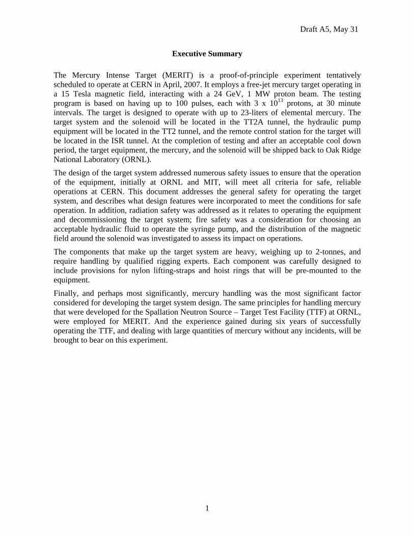
The primary function of the target system is to deliver the mercury jet in the form of a continuous stream, into the high field solenoid while simultaneously intersecting a high-energy (24-GeV) proton beam. The duration of the jet must be sufficient to interact with the 1-second duration of the peak field in the solenoid. The target system provides the means for discharging the Hg jet and collecting and recycling elemental mercury through a syringe pump system. The mercury delivery system is installed within a secondary containment boundary. Figure 1 is a CAD model of the MERIT system.
Figure 1. Hg target system with the secondary containment enclosure in place.
1.3 Material Compatibility Two criteria were adopted for selecting materials for the design of the target system: 1) compatibility with elemental mercury, e.g., resistance to mercury-induced corrosion, and 2) transparency to magnetic fields, e.g., use of non-ferromagnetic materials. Elemental mercury dissolves metals such as copper that might normally be used for flange gaskets.
Draft A5, May 31
3
Hence, any component or surface that could contact elemental mercury or its vapor is fabricated from materials that are relatively inert to mercury.
Non-magnetic material is used exclusively to avoid the forces that ferromagnetic materials experience in proximity to magnets. And, the gamma dose due to neutron activated materials in the target structure is estimated to be less than 104 rads, and all of the organic materials selected can easily withstand that level of radiation dose.
The following list summarizes the materials of construction for the MERIT system:
• austenitic stainless steel, type 316 or 304 – pump cylinders, piping, fittings and connectors, the storage tank,
• Nitronic 50 – tie rods for the cylinder assembly,
• buna-N elastomer – gasket material for removable cover seals,
• 6Al4V titanium alloy, grades 5 and 2 – proton beam windows, piping, nozzle,
• sapphire – laser diagnostic windows,
• Lexan® – secondary enclosure cover and the sump tank cover, and
• 6061 aluminum alloy – base support structure.
Fasteners and miscellaneous items are non-magnetic wherever practicable. Gaskets are non-reactive with mercury and capable of radiation tolerance to at least 105 rads. At the start of design, it was estimated that the total dose to the MERIT will not exceed 104 rads.
Draft A5, May 31
4
2.0 Design Specifications and Requirements
The target system consists of four subsystems: 1) the primary containment structure, 2) the secondary containment structure, 3) a syringe pump system, and 4) the support base structure. The design for each subsystem takes into account the requirements for dealing with elemental mercury, a toxic heavy metal that will become mildly activated once beam tests commence, and the requirements for dealing with mildly radioactive structure at the completion of testing.
The system will operate within a 1-atmosphere environment of air in the primary containment, and 1-atmosphere of air in the secondary containment. (Air-activation, i.e. 13N, 15O and 41Ar, will not be an issue for this system since the air environment is not purged after each pulse, and the containment boundaries remain intact for the duration of testing. If there is a need to breach either barrier after test operations commence, 1 hour of waiting will be sufficient for the decay of these isotopes. This approach is much simpler than incorporating equipment to evacuate and backfill with helium because of the complications of installing a mercury ventilation/filtration system.)
The target system consists of the equipment to produce a mercury jet for a duration of up to 12 seconds. For the 12 second jet, the MERIT requires 23 liters of mercury. Testing at ORNL will determine the necessary jet duration, and hence, the quantity of mercury needed for beam tests at CERN.
The equipment is designed so that the elemental mercury in the target equipment is double-contained and mounted on a base structure that supports the target equipment and the solenoid system as an integrated unit. The support structure can be manually driven (pushed on Hilman® rollers) into or out of the axis of the proton beam line, and it has provisions to adjust the elevation and pitch of the integrated system.
The target system will be assembled initially with unlimited “hands on” access but must be maintained and operated with minimal personal contact after beam operations commence. Therefore, design of the target system has taken into account the eventual disassembly and handling of the equipment for shipment back to ORNL. The design features incorporated into the target system considered handling mildly activated components that are mercury-contaminated, as well as handling activated mercury in order to minimize exposure to personnel.
2.1 Design Specification - ISO 2919
Design of the target system used the criteria of ISO 2919, Table 2 “Classification of Sealed Source Performance,” Class 2, as a starting point. This requirement was suggested early in the project by the CERN Safety Engineering Group, and was considered to be the minimum requirement needed to start the design of MERIT. Furthermore, it was established that these requirements could be met by analysis or engineering judgement, in lieu of performance tests.
ISO 2919, Table 2, Class 2 Temperature -40º C (20 minutes), +80º C (1 hour) [-40° F and +176° F]
All of the materials listed in Section 1.3 are suitable for operation in the temperature range stated above, including the buna-N elastomer which has an operating range of -40º C to +100º C. Also, the Lexan® cover has an operating temperature range of -135º C to +115º C.
Draft A5, May 31
5
External Pressure 25 kPa absolute (60 psi) to atmospheric
This is not applicable to the secondary enclosure because it does not appear possible for the pressure in the tunnel to exceed one atmosphere.
Impact 50 grams (1-3/4 oz.) from 1 meter, or equivalent imparted energy
The most vulnerable component in the target system is the sapphire windows. A successful impact test on a 6-mm thick sapphire window was done using a 1.75-cm diameter “paintball,” with a speed of 95 m/s. Its momentum was the same as that of a 7-mm diameter mercury droplet with a velocity of 95 m/s. [4]
Vibration 3 times 10 minutes, 25-500 Hz at 49 m/s2 (5 gn, acceleration
maximum amplitude) Presumably, this could apply to the target equipment located in the TT2A tunnel to prevent the equipment from moving during a seismic event. If this is deemed to be a requirement, the base support structure can be anchored to the tunnel floor.
Puncture 1 gram (0.03 oz.) from 1 meter, or equivalent imparted energy
By inference, a sharp object with such little momentum will not penetrate any portion of the 12.7-mm thick Lexan® cover or the 6-mm thick stainless steel sides of the secondary enclosure.
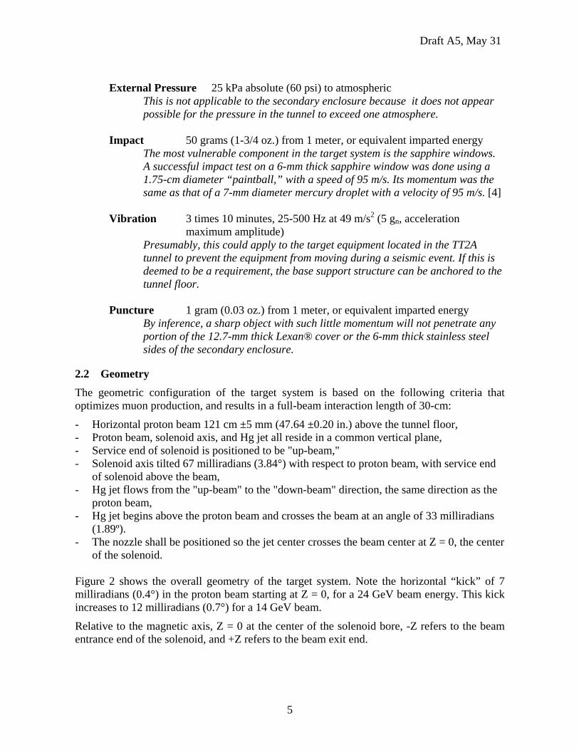
2.2 Geometry The geometric configuration of the target system is based on the following criteria that optimizes muon production, and results in a full-beam interaction length of 30-cm:
- Horizontal proton beam 121 cm ±5 mm (47.64 ±0.20 in.) above the tunnel floor, - Proton beam, solenoid axis, and Hg jet all reside in a common vertical plane, - Service end of solenoid is positioned to be "up-beam," - Solenoid axis tilted 67 milliradians (3.84°) with respect to proton beam, with service end
of solenoid above the beam, - Hg jet flows from the "up-beam" to the "down-beam" direction, the same direction as the
proton beam, - Hg jet begins above the proton beam and crosses the beam at an angle of 33 milliradians
(1.89º). - The nozzle shall be positioned so the jet center crosses the beam center at Z = 0, the center
of the solenoid. Figure 2 shows the overall geometry of the target system. Note the horizontal “kick” of 7 milliradians (0.4°) in the proton beam starting at Z = 0, for a 24 GeV beam energy. This kick increases to 12 milliradians (0.7°) for a 14 GeV beam.
Relative to the magnetic axis, Z = 0 at the center of the solenoid bore, -Z refers to the beam entrance end of the solenoid, and +Z refers to the beam exit end.
Draft A5, May 31
6
Figure 2. Baseline geometry configuration for MERIT.
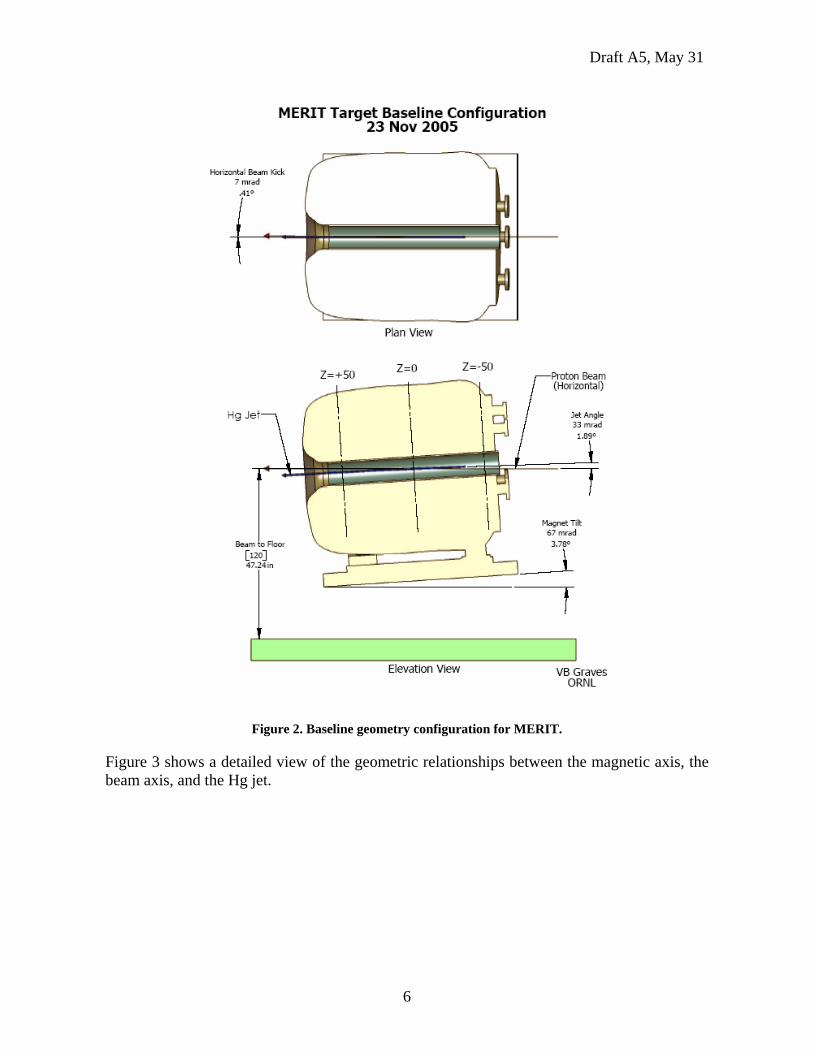
Figure 3 shows a detailed view of the geometric relationships between the magnetic axis, the beam axis, and the Hg jet.
Draft A5, May 31
7
Figure 3. Nozzle and solenoid relative to beam.
2.3 Operating Temperature The operating temperature of the mercury is estimated to be between 15 C° and 35 C°. Testing at ORNL will determine the actual temperature rise after each pulse of the jet, by monitoring the temperature sensor located in the sump tank. The goal is to ensure that the temperature rise in the mercury inventory remains well below the boiling point of Hg. This should be easily demonstrated because the dwell time between pulses is nominally 30 minutes. The results of the ORNL will be documented and added as an Addendum to this document.
2.4 Mercury Containment Boundaries
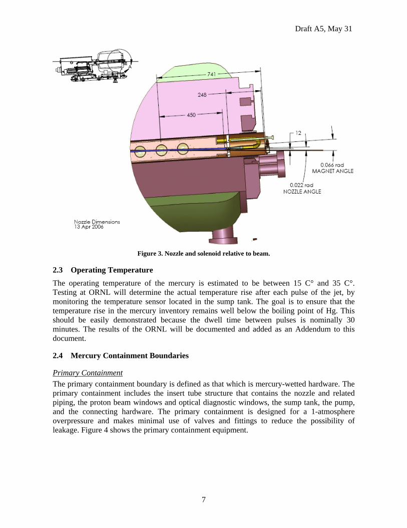
Primary Containment The primary containment boundary is defined as that which is mercury-wetted hardware. The primary containment includes the insert tube structure that contains the nozzle and related piping, the proton beam windows and optical diagnostic windows, the sump tank, the pump, and the connecting hardware. The primary containment is designed for a 1-atmosphere overpressure and makes minimal use of valves and fittings to reduce the possibility of leakage. Figure 4 shows the primary containment equipment.
Draft A5, May 31
8
Figure 4. Primary containment for the target system including the syringe pump equipment.
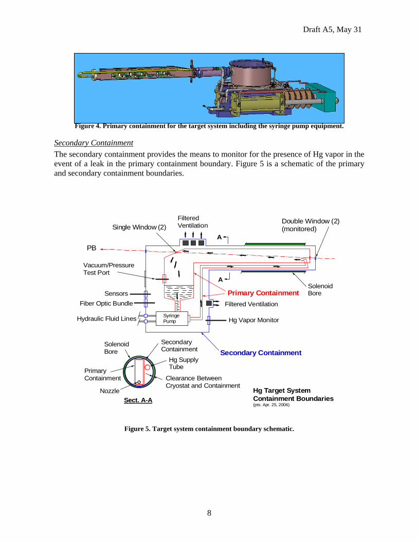
Secondary Containment The secondary containment provides the means to monitor for the presence of Hg vapor in the event of a leak in the primary containment boundary. Figure 5 is a schematic of the primary and secondary containment boundaries.
Double Window (2)(monitored)
Primary Containment
Secondary Containment
PB
Single Window (2)
SolenoidBore
SecondaryContainment
PrimaryContainment Clearance Between
Cryostat and ContainmentHg Target SystemContainment Boundaries(pts: Apr. 25, 2006)
Sect. A-A
Hg SupplyTube
Nozzle
SolenoidBore
A
A
Fiber Optic Bundle
Hydraulic Fluid Lines
Vacuum/PressureTest Port
FilteredVentilation
Sensors
SyringePump Hg Vapor Monitor
Filtered Ventilation
Figure 5. Target system containment boundary schematic.
Draft A5, May 31
9
2.5 Windows
Primary Containment Windows Two types of windows are mounted to the primary containment boundary, the proton beam windows and the diagnostic optical windows [1]. The proton beam windows are single-layer, made from Ti6Al4V material. The diagnostic windows are optically transparent, single layer, made from sapphire material. The diagnostic windows provide the ability to optically view the interaction region at four locations along the axis of the proton beam line. The diagnostic windows and the laser components will be provided by BNL. They were designed to meet the interface requirements of the primary containment; therefore the diagnostic equipment will be installed as a module.
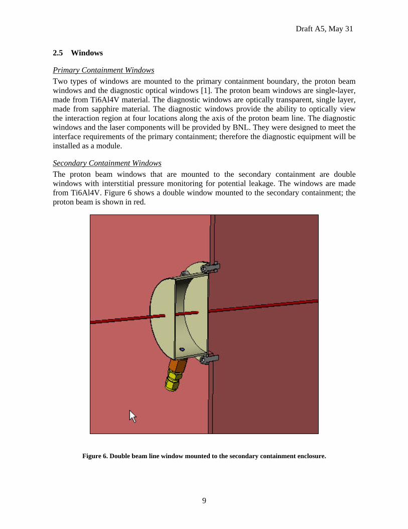
Secondary Containment Windows The proton beam windows that are mounted to the secondary containment are double windows with interstitial pressure monitoring for potential leakage. The windows are made from Ti6Al4V. Figure 6 shows a double window mounted to the secondary containment; the proton beam is shown in red.
Figure 6. Double beam line window mounted to the secondary containment enclosure.
Draft A5, May 31
10
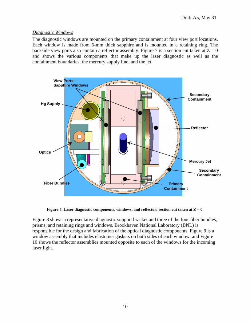
Diagnostic Windows The diagnostic windows are mounted on the primary containment at four view port locations. Each window is made from 6-mm thick sapphire and is mounted in a retaining ring. The backside view ports also contain a reflector assembly. Figure 7 is a section cut taken at Z = 0 and shows the various components that make up the laser diagnostic as well as the containment boundaries, the mercury supply line, and the jet.
Figure 7. Laser diagnostic components, windows, and reflector; section cut taken at Z = 0.
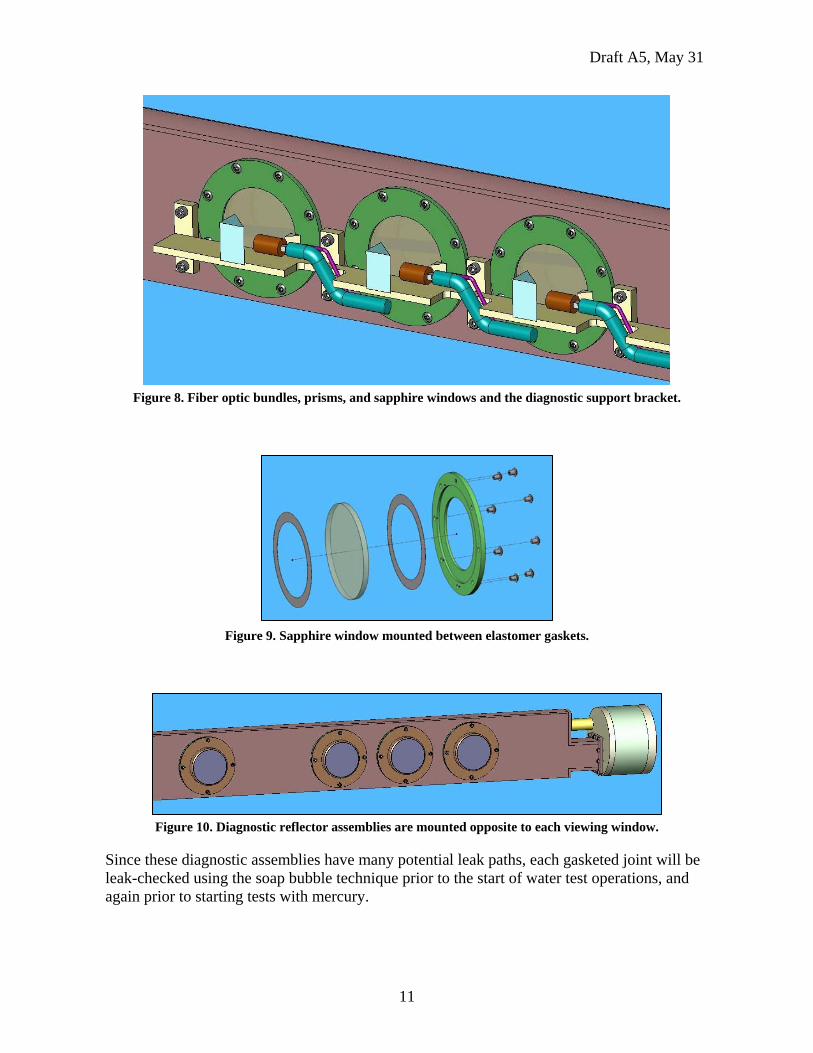
Figure 8 shows a representative diagnostic support bracket and three of the four fiber bundles, prisms, and retaining rings and windows. Brookhaven National Laboratory (BNL) is responsible for the design and fabrication of the optical diagnostic components. Figure 9 is a window assembly that includes elastomer gaskets on both sides of each window, and Figure 10 shows the reflector assemblies mounted opposite to each of the windows for the incoming laser light.
Reflector
Secondary Containment
Mercury Jet
Primary Containment
Hg Supply
Optics
Fiber Bundles
View Ports – Sapphire Windows
Secondary Containment
Draft A5, May 31
11
Figure 8. Fiber optic bundles, prisms, and sapphire windows and the diagnostic support bracket.
Figure 9. Sapphire window mounted between elastomer gaskets.
Figure 10. Diagnostic reflector assemblies are mounted opposite to each viewing window.
Since these diagnostic assemblies have many potential leak paths, each gasketed joint will be leak-checked using the soap bubble technique prior to the start of water test operations, and again prior to starting tests with mercury.
Draft A5, May 31
12
2.6 Alignment The target system base support structure has provisions to align the assembled target for insertion into the solenoid bore, and provisions to position the assembled solenoid/target system to the proton beam line, to within 1-mm. The position of the solenoid/target will be determined by taking measurements from fiducials mounted to the solenoid and from beam diagnostic measurements made by the CERN PS group.
2.7 Assembly and Shipping The design and fabrication of the target system and the base support structure carefully considered the ease of assembly and disassembly, handling for transport, and handling for installation. Initially, the equipment will be shipped to MIT and back to ORNL by truck, and then to CERN in a sealand container. The target system was designed to meet the space requirements for moving components from above ground at CERN, into the tunnel areas leading to tunnel TT2A, and for the handling requirements needed by the CERN Rigging Group. Each major component has provisions for overhead lifting and pallet-like handling, and the base support structure has rotatable casters for moving the assembled target system into (and out of) the beam line. Section 6.0 discusses details about the packing and transportation of the target equipment (and the solenoid).
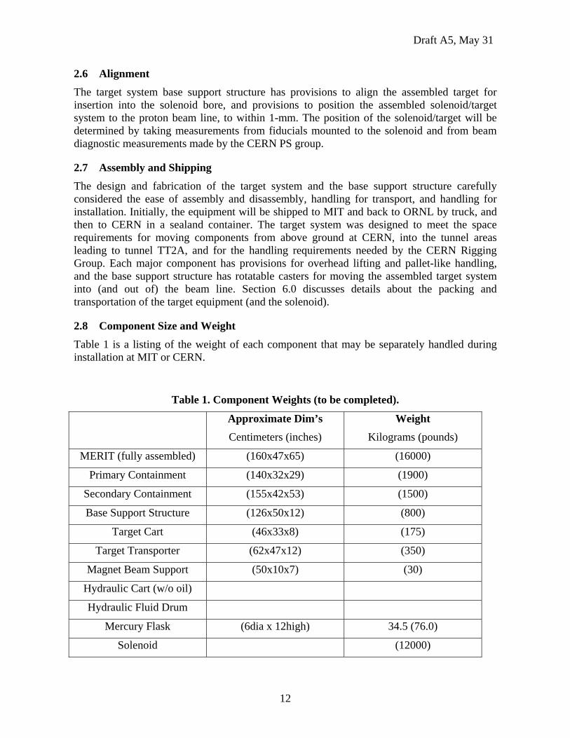
2.8 Component Size and Weight Table 1 is a listing of the weight of each component that may be separately handled during installation at MIT or CERN.
Table 1. Component Weights (to be completed).
Approximate Dim’s Centimeters (inches)
Weight Kilograms (pounds)
MERIT (fully assembled) (160x47x65) (16000)
Primary Containment (140x32x29) (1900)
Secondary Containment (155x42x53) (1500)
Base Support Structure (126x50x12) (800)
Target Cart (46x33x8) (175)
Target Transporter (62x47x12) (350)
Magnet Beam Support (50x10x7) (30)
Hydraulic Cart (w/o oil)
Hydraulic Fluid Drum
Mercury Flask (6dia x 12high) 34.5 (76.0)
Solenoid (12000)
Draft A5, May 31
13
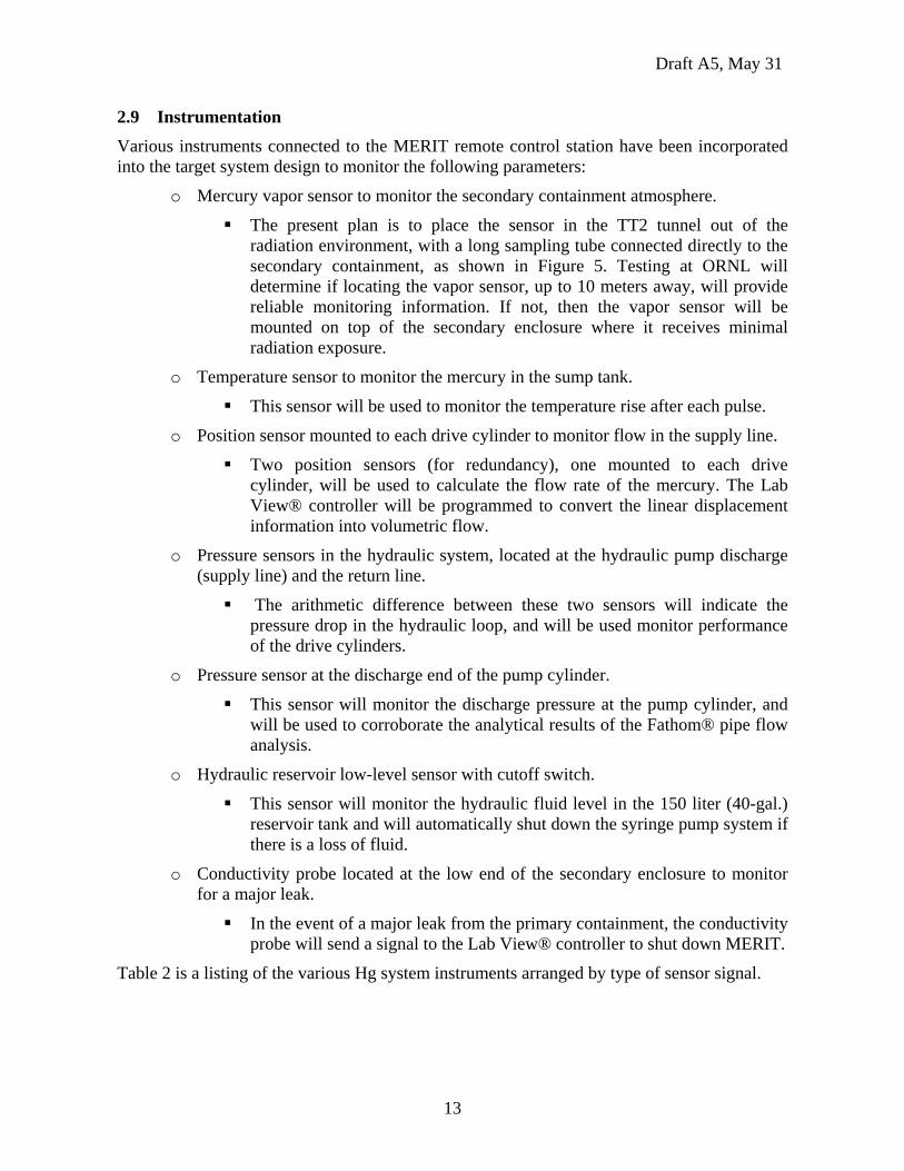
2.9 Instrumentation Various instruments connected to the MERIT remote control station have been incorporated into the target system design to monitor the following parameters:
o Mercury vapor sensor to monitor the secondary containment atmosphere.
The present plan is to place the sensor in the TT2 tunnel out of the radiation environment, with a long sampling tube connected directly to the secondary containment, as shown in Figure 5. Testing at ORNL will determine if locating the vapor sensor, up to 10 meters away, will provide reliable monitoring information. If not, then the vapor sensor will be mounted on top of the secondary enclosure where it receives minimal radiation exposure.
o Temperature sensor to monitor the mercury in the sump tank.
This sensor will be used to monitor the temperature rise after each pulse.
o Position sensor mounted to each drive cylinder to monitor flow in the supply line.
Two position sensors (for redundancy), one mounted to each drive cylinder, will be used to calculate the flow rate of the mercury. The Lab View® controller will be programmed to convert the linear displacement information into volumetric flow.
o Pressure sensors in the hydraulic system, located at the hydraulic pump discharge (supply line) and the return line.
The arithmetic difference between these two sensors will indicate the pressure drop in the hydraulic loop, and will be used monitor performance of the drive cylinders.
o Pressure sensor at the discharge end of the pump cylinder.
This sensor will monitor the discharge pressure at the pump cylinder, and will be used to corroborate the analytical results of the Fathom® pipe flow analysis.
o Hydraulic reservoir low-level sensor with cutoff switch.
This sensor will monitor the hydraulic fluid level in the 150 liter (40-gal.) reservoir tank and will automatically shut down the syringe pump system if there is a loss of fluid.
o Conductivity probe located at the low end of the secondary enclosure to monitor for a major leak.
In the event of a major leak from the primary containment, the conductivity probe will send a signal to the Lab View® controller to shut down MERIT.
Table 2 is a listing of the various Hg system instruments arranged by type of sensor signal.
Draft A5, May 31
14
Table 2. List of sensors for the target system.
* Denotes a critical sensor for system operation or safety.
It is important to keep in mind that the main purpose of the sensors is to provide the operator with information that cannot be viewed directly because of the hazardous environment during testing, and the fact that the operator will be located approximately 50 meters away.
Finally, although these are not instruments, it is worth mentioning that the top cover of the secondary enclosure is clear Lexan®. This permits visual inspection of the syringe pump equipment, and viewing the tests with water and mercury during ORNL testing. The top cover of the sump tank is also Lexan® which permits viewing the return flow of water and mercury into the sump tank, after the jet impinges on the down beam primary window.
2.10 Stray Magnetic Fields
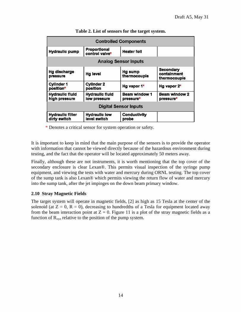
The target system will operate in magnetic fields, [2] as high as 15 Tesla at the center of the solenoid (at Z = 0, R = 0), decreasing to hundredths of a Tesla for equipment located away from the beam interaction point at Z = 0. Figure 11 is a plot of the stray magnetic fields as a function of Rxyz relative to the position of the pump system.
Draft A5, May 31
15
Figure 11. Stray magnetic field plot around the solenoid and the target equipment; 15 T is at the center of
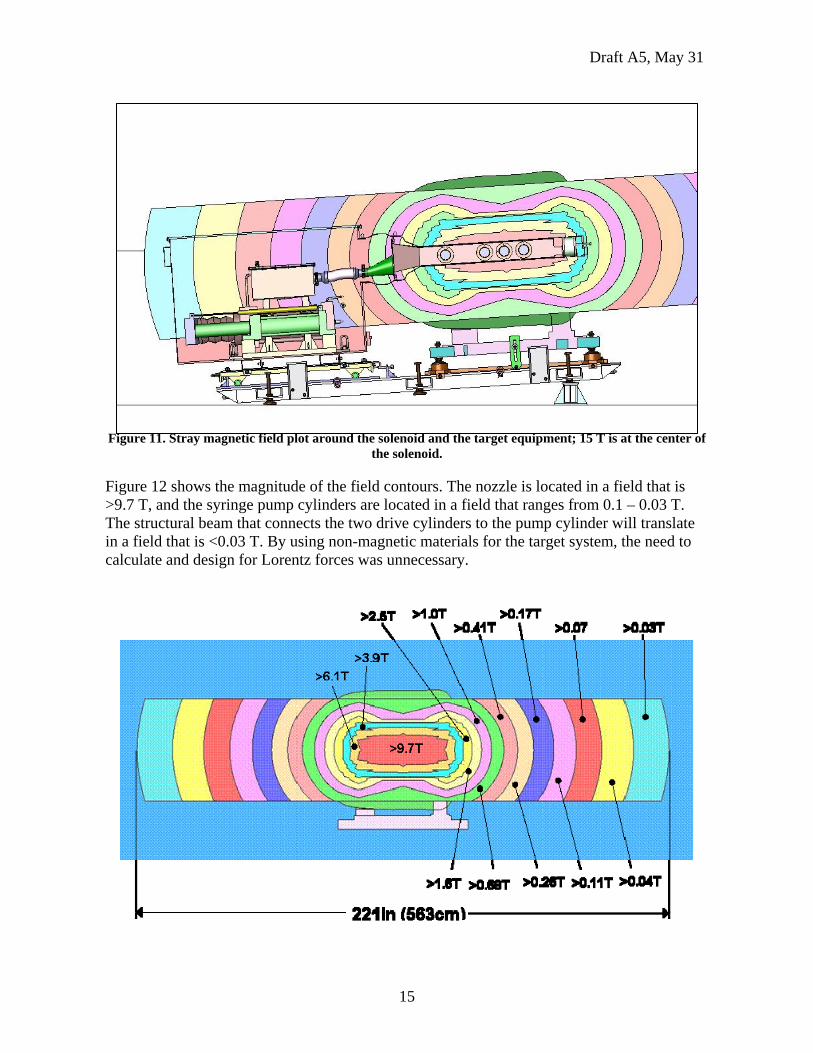
the solenoid.
Figure 12 shows the magnitude of the field contours. The nozzle is located in a field that is >9.7 T, and the syringe pump cylinders are located in a field that ranges from 0.1 – 0.03 T. The structural beam that connects the two drive cylinders to the pump cylinder will translate in a field that is <0.03 T. By using non-magnetic materials for the target system, the need to calculate and design for Lorentz forces was unnecessary.
Draft A5, May 31
16
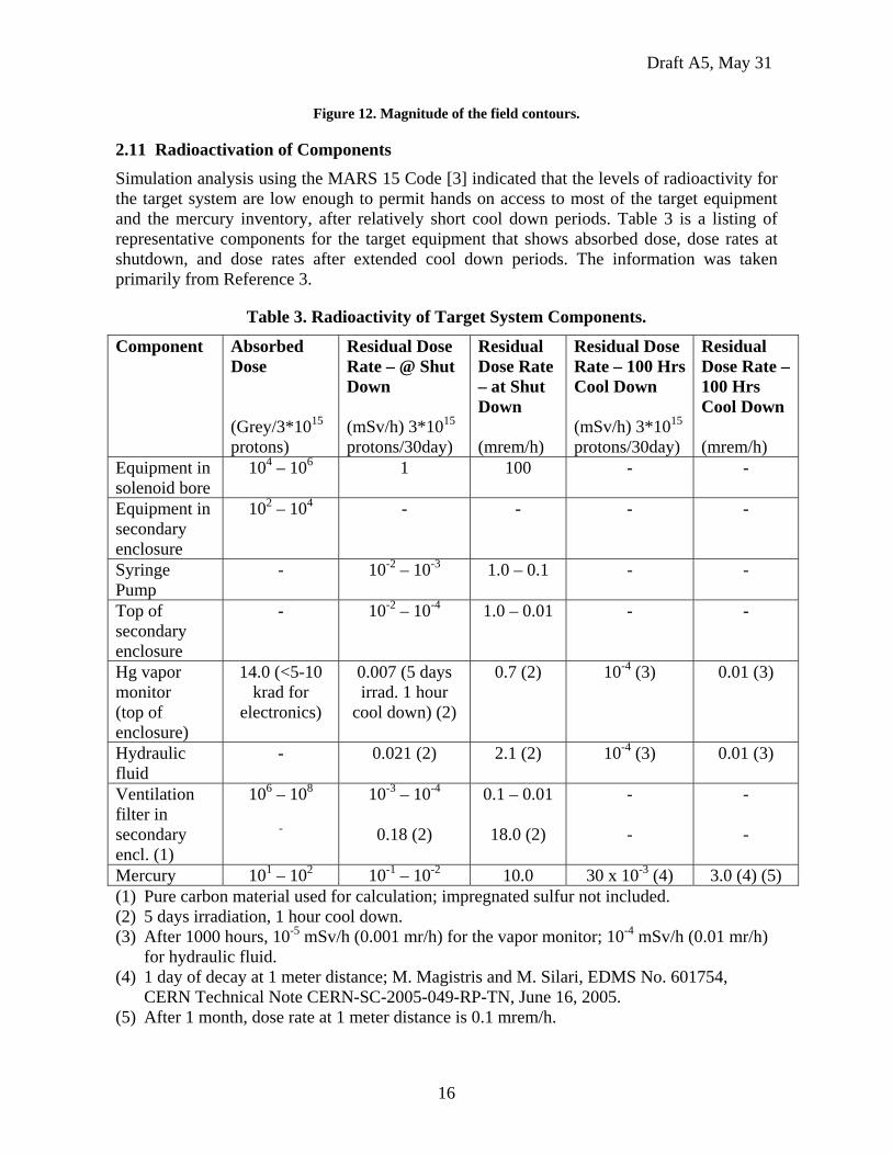
Figure 12. Magnitude of the field contours.
2.11 Radioactivation of Components Simulation analysis using the MARS 15 Code [3] indicated that the levels of radioactivity for the target system are low enough to permit hands on access to most of the target equipment and the mercury inventory, after relatively short cool down periods. Table 3 is a listing of representative components for the target equipment that shows absorbed dose, dose rates at shutdown, and dose rates after extended cool down periods. The information was taken primarily from Reference 3.
Table 3. Radioactivity of Target System Components.
Component Absorbed Dose (Grey/3*1015 protons)
Residual Dose Rate – @ Shut Down (mSv/h) 3*1015 protons/30day)
Residual Dose Rate – at Shut Down (mrem/h)
Residual Dose Rate – 100 Hrs Cool Down (mSv/h) 3*1015 protons/30day)
Residual Dose Rate – 100 Hrs Cool Down (mrem/h)
Equipment in solenoid bore
104 – 106 1 100 - -
Equipment in secondary enclosure
102 – 104 - - - -
Syringe Pump
- 10-2 – 10-3 1.0 – 0.1 - -
Top of secondary enclosure
- 10-2 – 10-4 1.0 – 0.01 - -
Hg vapor monitor (top of enclosure)
14.0 (<5-10 krad for
electronics)
0.007 (5 days irrad. 1 hour
cool down) (2)
0.7 (2) 10-4 (3) 0.01 (3)
Hydraulic fluid
- 0.021 (2) 2.1 (2) 10-4 (3) 0.01 (3)
Ventilation filter in secondary encl. (1)
106 – 108
-
10-3 – 10-4
0.18 (2)
0.1 – 0.01
18.0 (2)
- -
- -
Mercury 101 – 102 10-1 – 10-2 10.0 30 x 10-3 (4) 3.0 (4) (5) (1) Pure carbon material used for calculation; impregnated sulfur not included. (2) 5 days irradiation, 1 hour cool down. (3) After 1000 hours, 10-5 mSv/h (0.001 mr/h) for the vapor monitor; 10-4 mSv/h (0.01 mr/h)
for hydraulic fluid. (4) 1 day of decay at 1 meter distance; M. Magistris and M. Silari, EDMS No. 601754,
CERN Technical Note CERN-SC-2005-049-RP-TN, June 16, 2005. (5) After 1 month, dose rate at 1 meter distance is 0.1 mrem/h.
Draft A5, May 31
17
3.0 Component Design and Analysis
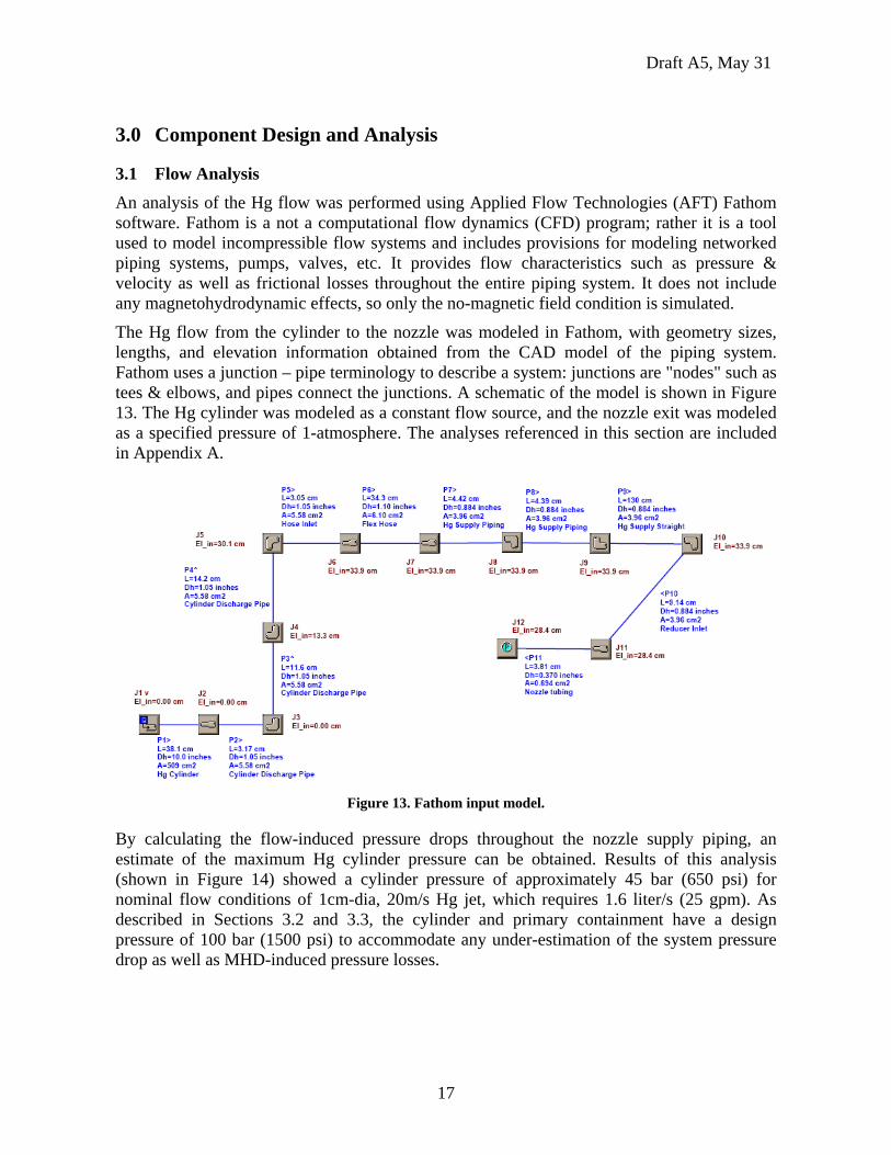
3.1 Flow Analysis An analysis of the Hg flow was performed using Applied Flow Technologies (AFT) Fathom software. Fathom is a not a computational flow dynamics (CFD) program; rather it is a tool used to model incompressible flow systems and includes provisions for modeling networked piping systems, pumps, valves, etc. It provides flow characteristics such as pressure & velocity as well as frictional losses throughout the entire piping system. It does not include any magnetohydrodynamic effects, so only the no-magnetic field condition is simulated.
The Hg flow from the cylinder to the nozzle was modeled in Fathom, with geometry sizes, lengths, and elevation information obtained from the CAD model of the piping system. Fathom uses a junction – pipe terminology to describe a system: junctions are "nodes" such as tees & elbows, and pipes connect the junctions. A schematic of the model is shown in Figure 13. The Hg cylinder was modeled as a constant flow source, and the nozzle exit was modeled as a specified pressure of 1-atmosphere. The analyses referenced in this section are included in Appendix A.
Figure 13. Fathom input model.
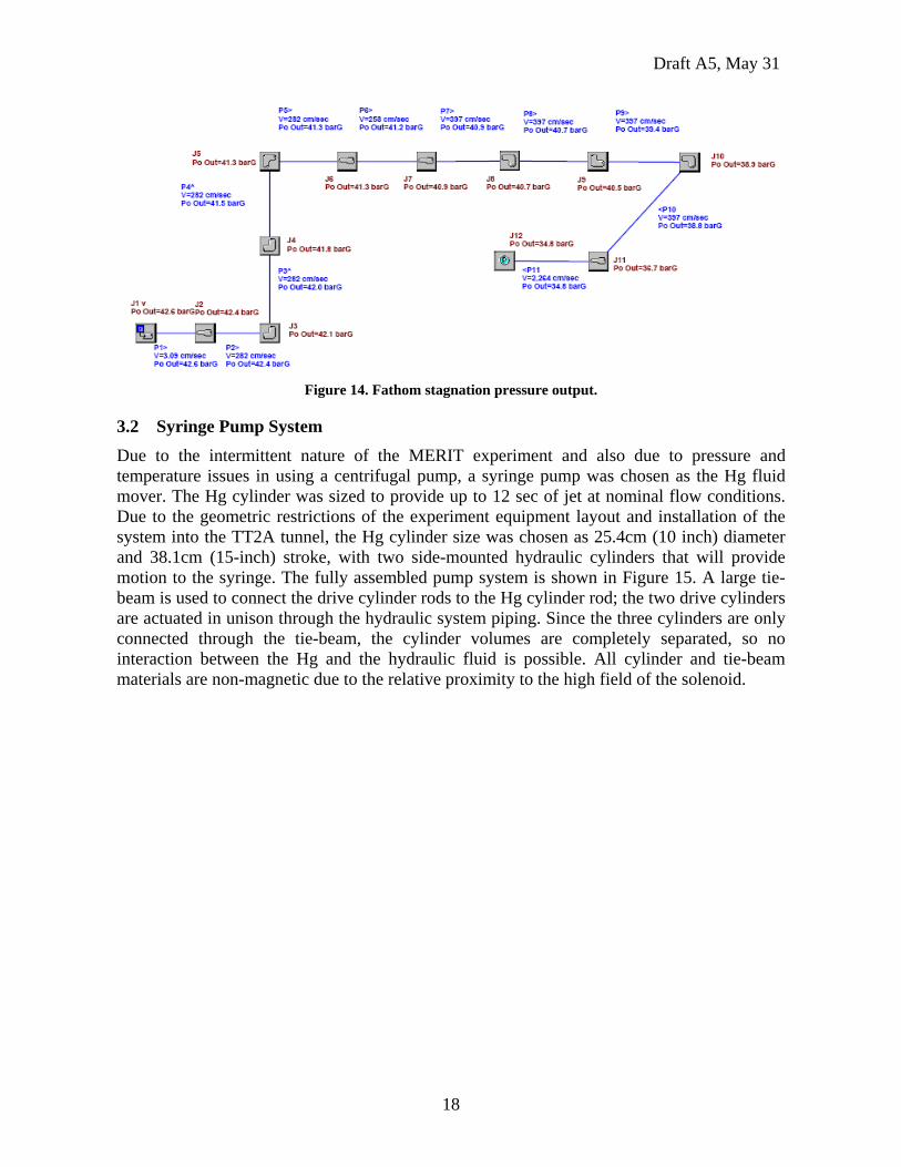
By calculating the flow-induced pressure drops throughout the nozzle supply piping, an estimate of the maximum Hg cylinder pressure can be obtained. Results of this analysis (shown in Figure 14) showed a cylinder pressure of approximately 45 bar (650 psi) for nominal flow conditions of 1cm-dia, 20m/s Hg jet, which requires 1.6 liter/s (25 gpm). As described in Sections 3.2 and 3.3, the cylinder and primary containment have a design pressure of 100 bar (1500 psi) to accommodate any under-estimation of the system pressure drop as well as MHD-induced pressure losses.
Draft A5, May 31
18
Figure 14. Fathom stagnation pressure output.
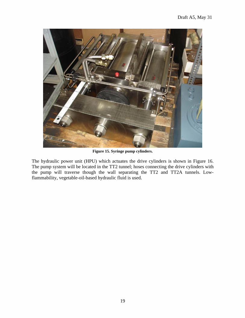
3.2 Syringe Pump System Due to the intermittent nature of the MERIT experiment and also due to pressure and temperature issues in using a centrifugal pump, a syringe pump was chosen as the Hg fluid mover. The Hg cylinder was sized to provide up to 12 sec of jet at nominal flow conditions. Due to the geometric restrictions of the experiment equipment layout and installation of the system into the TT2A tunnel, the Hg cylinder size was chosen as 25.4cm (10 inch) diameter and 38.1cm (15-inch) stroke, with two side-mounted hydraulic cylinders that will provide motion to the syringe. The fully assembled pump system is shown in Figure 15. A large tie-beam is used to connect the drive cylinder rods to the Hg cylinder rod; the two drive cylinders are actuated in unison through the hydraulic system piping. Since the three cylinders are only connected through the tie-beam, the cylinder volumes are completely separated, so no interaction between the Hg and the hydraulic fluid is possible. All cylinder and tie-beam materials are non-magnetic due to the relative proximity to the high field of the solenoid.
Draft A5, May 31
19
Figure 15. Syringe pump cylinders.
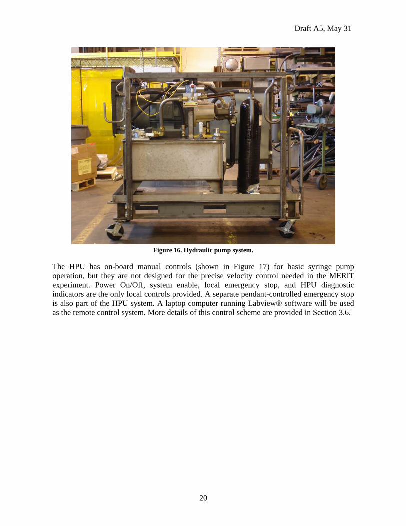
The hydraulic power unit (HPU) which actuates the drive cylinders is shown in Figure 16. The pump system will be located in the TT2 tunnel; hoses connecting the drive cylinders with the pump will traverse though the wall separating the TT2 and TT2A tunnels. Low-flammability, vegetable-oil-based hydraulic fluid is used.
Draft A5, May 31
20
Figure 16. Hydraulic pump system.
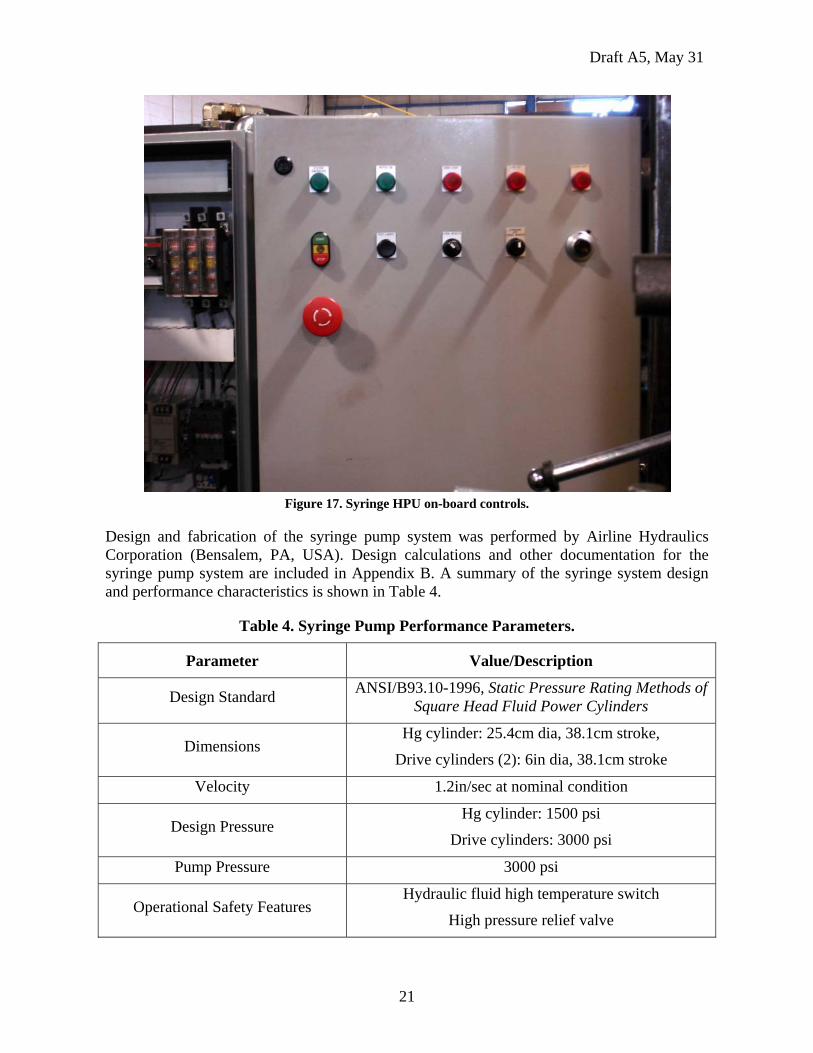
The HPU has on-board manual controls (shown in Figure 17) for basic syringe pump operation, but they are not designed for the precise velocity control needed in the MERIT experiment. Power On/Off, system enable, local emergency stop, and HPU diagnostic indicators are the only local controls provided. A separate pendant-controlled emergency stop is also part of the HPU system. A laptop computer running Labview® software will be used as the remote control system. More details of this control scheme are provided in Section 3.6.
Draft A5, May 31
21
Figure 17. Syringe HPU on-board controls.
Design and fabrication of the syringe pump system was performed by Airline Hydraulics Corporation (Bensalem, PA, USA). Design calculations and other documentation for the syringe pump system are included in Appendix B. A summary of the syringe system design and performance characteristics is shown in Table 4.
Table 4. Syringe Pump Performance Parameters.
Parameter Value/Description
Design Standard ANSI/B93.10-1996, Static Pressure Rating Methods of Square Head Fluid Power Cylinders
Dimensions Hg cylinder: 25.4cm dia, 38.1cm stroke,
Drive cylinders (2): 6in dia, 38.1cm stroke
Velocity 1.2in/sec at nominal condition
Design Pressure Hg cylinder: 1500 psi
Drive cylinders: 3000 psi
Pump Pressure 3000 psi
Operational Safety Features Hydraulic fluid high temperature switch
High pressure relief valve
Draft A5, May 31
22
Parameter Value/Description
Hoses 3/8inch, stainless steel
Hydraulic Pump Reservoir 40 gal
Hydraulic Fluid Quintalubric-888
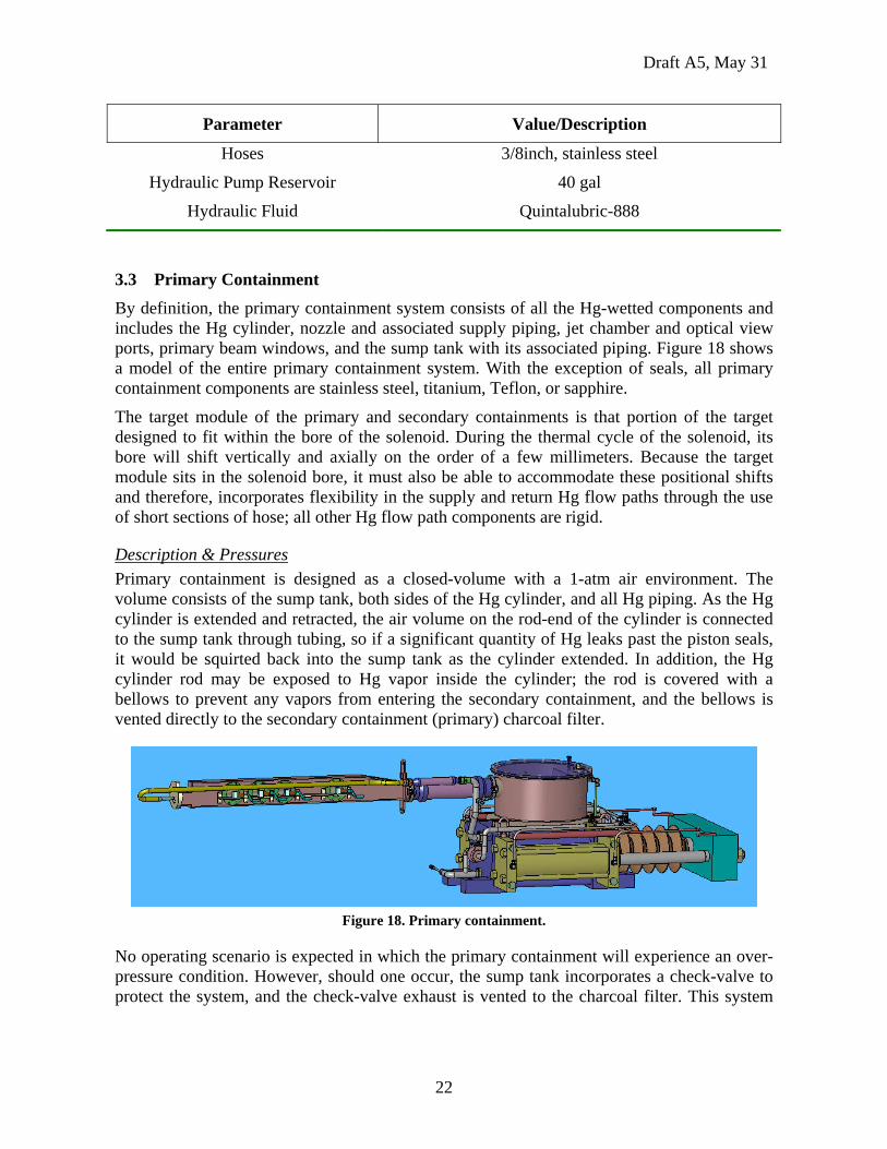
3.3 Primary Containment By definition, the primary containment system consists of all the Hg-wetted components and includes the Hg cylinder, nozzle and associated supply piping, jet chamber and optical view ports, primary beam windows, and the sump tank with its associated piping. Figure 18 shows a model of the entire primary containment system. With the exception of seals, all primary containment components are stainless steel, titanium, Teflon, or sapphire.
The target module of the primary and secondary containments is that portion of the target designed to fit within the bore of the solenoid. During the thermal cycle of the solenoid, its bore will shift vertically and axially on the order of a few millimeters. Because the target module sits in the solenoid bore, it must also be able to accommodate these positional shifts and therefore, incorporates flexibility in the supply and return Hg flow paths through the use of short sections of hose; all other Hg flow path components are rigid.
Description & Pressures Primary containment is designed as a closed-volume with a 1-atm air environment. The volume consists of the sump tank, both sides of the Hg cylinder, and all Hg piping. As the Hg cylinder is extended and retracted, the air volume on the rod-end of the cylinder is connected to the sump tank through tubing, so if a significant quantity of Hg leaks past the piston seals, it would be squirted back into the sump tank as the cylinder extended. In addition, the Hg cylinder rod may be exposed to Hg vapor inside the cylinder; the rod is covered with a bellows to prevent any vapors from entering the secondary containment, and the bellows is vented directly to the secondary containment (primary) charcoal filter.
Figure 18. Primary containment.
No operating scenario is expected in which the primary containment will experience an over-pressure condition. However, should one occur, the sump tank incorporates a check-valve to protect the system, and the check-valve exhaust is vented to the charcoal filter. This system
Draft A5, May 31
23
may actuate during the Hg fill operation since the Hg will displace air inside the primary containment.
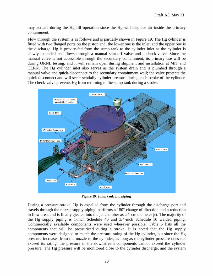
Flow through the system is as follows and is partially shown in Figure 19. The Hg cylinder is fitted with two flanged ports on the piston end; the lower one is the inlet, and the upper one is the discharge. Hg is gravity-fed from the sump tank to the cylinder inlet as the cylinder is slowly extended and flows through a manual shut-off valve and a check-valve. Since the manual valve is not accessible through the secondary containment, its primary use will be during ORNL testing, and it will remain open during shipment and installation at MIT and CERN. The Hg cylinder inlet also serves as the system drain and is plumbed through a manual valve and quick-disconnect to the secondary containment wall; the valve protects the quick-disconnect and will see essentially cylinder pressure during each stroke of the cylinder. The check-valve prevents Hg from returning to the sump tank during a stroke.
Figure 19. Sump tank and piping.
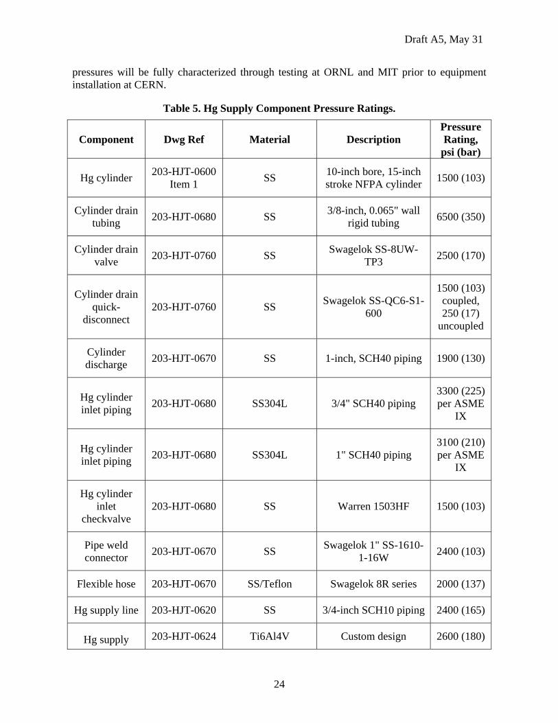
During a pressure stroke, Hg is expelled from the cylinder through the discharge port and travels through the nozzle supply piping, performs a 180° change of direction and a reduction in flow area, and is finally ejected into the jet chamber as a 1-cm diameter jet. The majority of the Hg supply piping is 1-inch Schedule 40 and 3/4-inch Schedule 10 welded piping. Commercially available components were used wherever possible. Table 5 lists all the components that will be pressurized during a stroke. It is noted that the Hg supply components were designed to match the pressure rating of the Hg cylinder, but since the Hg pressure increases from the nozzle to the cylinder, as long as the cylinder pressure does not exceed its rating, the pressure in the downstream components cannot exceed the cylinder pressure. The Hg pressure will be monitored close to the cylinder discharge, and the system
Draft A5, May 31
24
pressures will be fully characterized through testing at ORNL and MIT prior to equipment installation at CERN.
Table 5. Hg Supply Component Pressure Ratings.
Component Dwg Ref Material Description Pressure Rating,
psi (bar)
Hg cylinder 203-HJT-0600 Item 1 SS 10-inch bore, 15-inch
stroke NFPA cylinder 1500 (103)
Cylinder drain tubing 203-HJT-0680 SS 3/8-inch, 0.065" wall
rigid tubing 6500 (350)
Cylinder drain valve 203-HJT-0760 SS Swagelok SS-8UW-
TP3 2500 (170)
Cylinder drain quick-
disconnect 203-HJT-0760 SS Swagelok SS-QC6-S1-
600
1500 (103) coupled, 250 (17)
uncoupled
Cylinder discharge 203-HJT-0670 SS 1-inch, SCH40 piping 1900 (130)
Hg cylinder inlet piping 203-HJT-0680 SS304L 3/4" SCH40 piping
3300 (225) per ASME
IX
Hg cylinder inlet piping 203-HJT-0680 SS304L 1" SCH40 piping
3100 (210) per ASME
IX
Hg cylinder inlet
checkvalve 203-HJT-0680 SS Warren 1503HF 1500 (103)
Pipe weld connector 203-HJT-0670 SS Swagelok 1" SS-1610-
1-16W 2400 (103)
Flexible hose 203-HJT-0670 SS/Teflon Swagelok 8R series 2000 (137)
Hg supply line 203-HJT-0620 SS 3/4-inch SCH10 piping 2400 (165)
Hg supply 203-HJT-0624 Ti6Al4V Custom design 2600 (180)
Draft A5, May 31
25
Component Dwg Ref Material Description Pressure Rating,
psi (bar) reducer
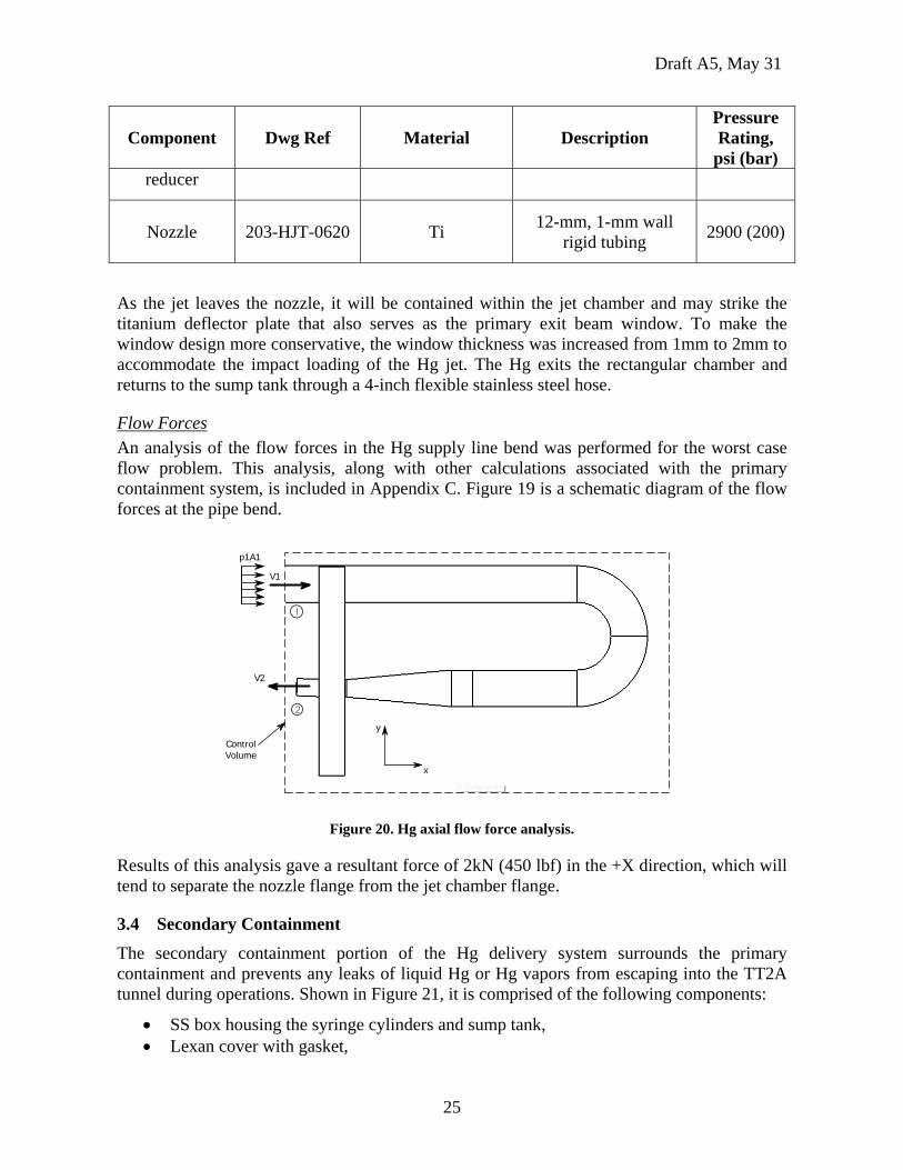
Nozzle 203-HJT-0620 Ti 12-mm, 1-mm wall rigid tubing 2900 (200)
As the jet leaves the nozzle, it will be contained within the jet chamber and may strike the titanium deflector plate that also serves as the primary exit beam window. To make the window design more conservative, the window thickness was increased from 1mm to 2mm to accommodate the impact loading of the Hg jet. The Hg exits the rectangular chamber and returns to the sump tank through a 4-inch flexible stainless steel hose.
Flow Forces An analysis of the flow forces in the Hg supply line bend was performed for the worst case flow problem. This analysis, along with other calculations associated with the primary containment system, is included in Appendix C. Figure 19 is a schematic diagram of the flow forces at the pipe bend.
1
V1
V2
2
ControlVolume
y
x
p1A1
Figure 20. Hg axial flow force analysis.
Results of this analysis gave a resultant force of 2kN (450 lbf) in the +X direction, which will tend to separate the nozzle flange from the jet chamber flange.
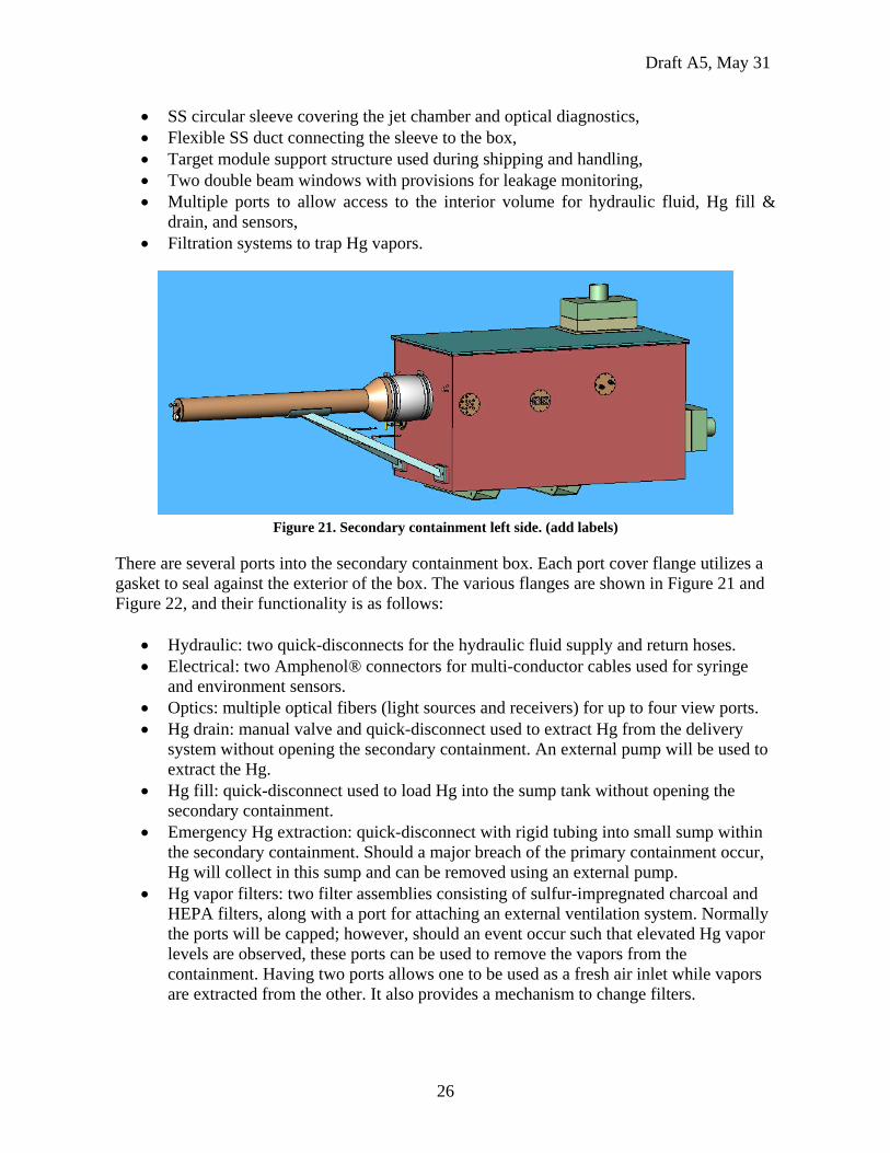
3.4 Secondary Containment The secondary containment portion of the Hg delivery system surrounds the primary containment and prevents any leaks of liquid Hg or Hg vapors from escaping into the TT2A tunnel during operations. Shown in Figure 21, it is comprised of the following components:
• SS box housing the syringe cylinders and sump tank, • Lexan cover with gasket,
Draft A5, May 31
26
• SS circular sleeve covering the jet chamber and optical diagnostics, • Flexible SS duct connecting the sleeve to the box, • Target module support structure used during shipping and handling, • Two double beam windows with provisions for leakage monitoring, • Multiple ports to allow access to the interior volume for hydraulic fluid, Hg fill &
drain, and sensors, • Filtration systems to trap Hg vapors.
Figure 21. Secondary containment left side. (add labels)
There are several ports into the secondary containment box. Each port cover flange utilizes a gasket to seal against the exterior of the box. The various flanges are shown in Figure 21 and Figure 22, and their functionality is as follows:
• Hydraulic: two quick-disconnects for the hydraulic fluid supply and return hoses. • Electrical: two Amphenol® connectors for multi-conductor cables used for syringe
and environment sensors. • Optics: multiple optical fibers (light sources and receivers) for up to four view ports. • Hg drain: manual valve and quick-disconnect used to extract Hg from the delivery
system without opening the secondary containment. An external pump will be used to extract the Hg.
• Hg fill: quick-disconnect used to load Hg into the sump tank without opening the secondary containment.
• Emergency Hg extraction: quick-disconnect with rigid tubing into small sump within the secondary containment. Should a major breach of the primary containment occur, Hg will collect in this sump and can be removed using an external pump.
• Hg vapor filters: two filter assemblies consisting of sulfur-impregnated charcoal and HEPA filters, along with a port for attaching an external ventilation system. Normally the ports will be capped; however, should an event occur such that elevated Hg vapor levels are observed, these ports can be used to remove the vapors from the containment. Having two ports allows one to be used as a fresh air inlet while vapors are extracted from the other. It also provides a mechanism to change filters.
Draft A5, May 31
27
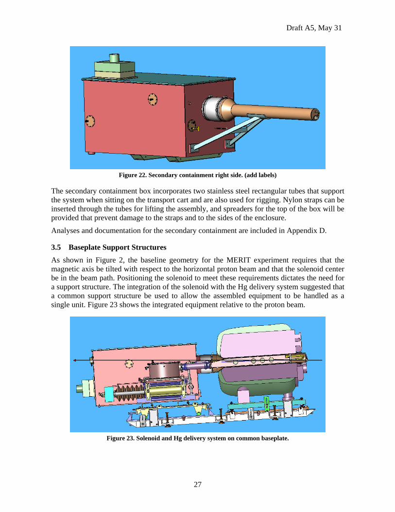
Figure 22. Secondary containment right side. (add labels)
The secondary containment box incorporates two stainless steel rectangular tubes that support the system when sitting on the transport cart and are also used for rigging. Nylon straps can be inserted through the tubes for lifting the assembly, and spreaders for the top of the box will be provided that prevent damage to the straps and to the sides of the enclosure.
Analyses and documentation for the secondary containment are included in Appendix D.
3.5 Baseplate Support Structures As shown in Figure 2, the baseline geometry for the MERIT experiment requires that the magnetic axis be tilted with respect to the horizontal proton beam and that the solenoid center be in the beam path. Positioning the solenoid to meet these requirements dictates the need for a support structure. The integration of the solenoid with the Hg delivery system suggested that a common support structure be used to allow the assembled equipment to be handled as a single unit. Figure 23 shows the integrated equipment relative to the proton beam.
Figure 23. Solenoid and Hg delivery system on common baseplate.
Draft A5, May 31
28
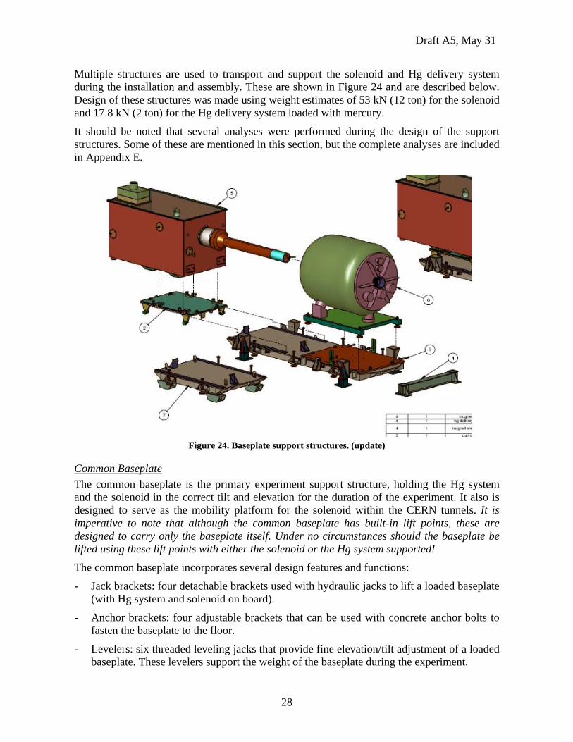
Multiple structures are used to transport and support the solenoid and Hg delivery system during the installation and assembly. These are shown in Figure 24 and are described below. Design of these structures was made using weight estimates of 53 kN (12 ton) for the solenoid and 17.8 kN (2 ton) for the Hg delivery system loaded with mercury.
It should be noted that several analyses were performed during the design of the support structures. Some of these are mentioned in this section, but the complete analyses are included in Appendix E.
Figure 24. Baseplate support structures. (update)
Common Baseplate The common baseplate is the primary experiment support structure, holding the Hg system and the solenoid in the correct tilt and elevation for the duration of the experiment. It also is designed to serve as the mobility platform for the solenoid within the CERN tunnels. It is imperative to note that although the common baseplate has built-in lift points, these are designed to carry only the baseplate itself. Under no circumstances should the baseplate be lifted using these lift points with either the solenoid or the Hg system supported!
The common baseplate incorporates several design features and functions:
- Jack brackets: four detachable brackets used with hydraulic jacks to lift a loaded baseplate (with Hg system and solenoid on board).
- Anchor brackets: four adjustable brackets that can be used with concrete anchor bolts to fasten the baseplate to the floor.
- Levelers: six threaded leveling jacks that provide fine elevation/tilt adjustment of a loaded baseplate. These levelers support the weight of the baseplate during the experiment.
Draft A5, May 31
29
- Rails: two stainless steel roller guides attached to the baseplate that allow the target cart to be transferred from the transporter to the common baseplate during target module insertion.
- Solenoid restraint brackets: two adjustable brackets which affix the magnet to the support plate upon which it sits.
- Cart positioning brackets: two brackets with jack bolts that hold the target cart in a fixed axial position during operations. Can also be used to provide fine axial positioning adjustment.
- Solenoid lateral positioning: two jack bolts on each side provide lateral position adjustment of the solenoid by sliding the magnet support plate over a low-friction surface.
- Tow hooks: one on each end used to maneuver the baseplate.
- Roller pads: three pads provide a means to set the baseplate onto high-capacity rollers during baseplate transport and gross positioning operations.
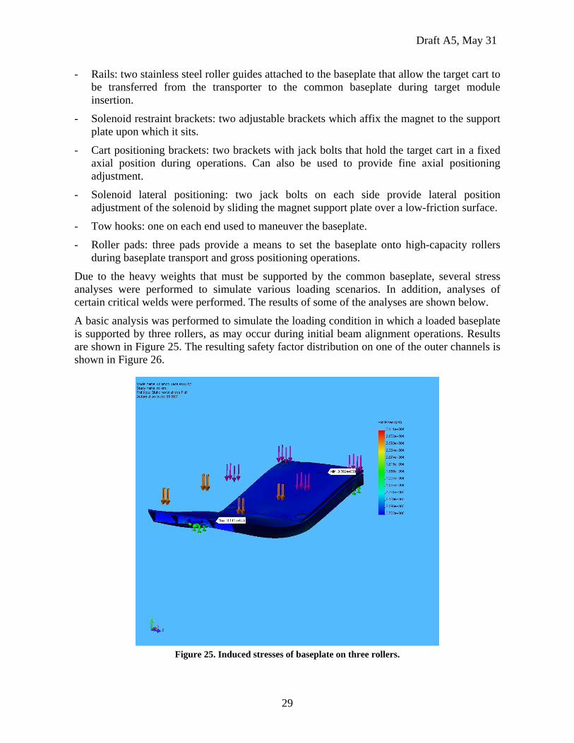
Due to the heavy weights that must be supported by the common baseplate, several stress analyses were performed to simulate various loading scenarios. In addition, analyses of certain critical welds were performed. The results of some of the analyses are shown below.
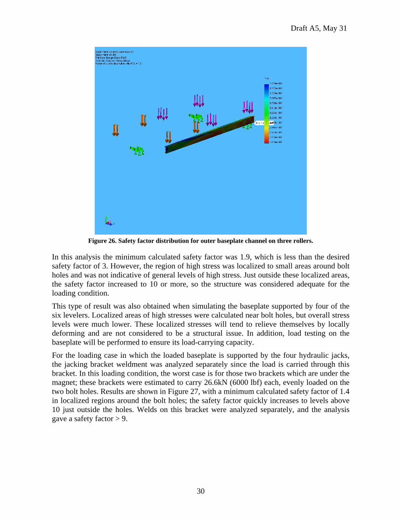
A basic analysis was performed to simulate the loading condition in which a loaded baseplate is supported by three rollers, as may occur during initial beam alignment operations. Results are shown in Figure 25. The resulting safety factor distribution on one of the outer channels is shown in Figure 26.
Figure 25. Induced stresses of baseplate on three rollers.
Draft A5, May 31
30
Figure 26. Safety factor distribution for outer baseplate channel on three rollers.
In this analysis the minimum calculated safety factor was 1.9, which is less than the desired safety factor of 3. However, the region of high stress was localized to small areas around bolt holes and was not indicative of general levels of high stress. Just outside these localized areas, the safety factor increased to 10 or more, so the structure was considered adequate for the loading condition.
This type of result was also obtained when simulating the baseplate supported by four of the six levelers. Localized areas of high stresses were calculated near bolt holes, but overall stress levels were much lower. These localized stresses will tend to relieve themselves by locally deforming and are not considered to be a structural issue. In addition, load testing on the baseplate will be performed to ensure its load-carrying capacity.
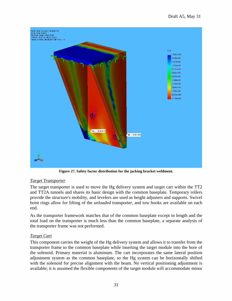
For the loading case in which the loaded baseplate is supported by the four hydraulic jacks, the jacking bracket weldment was analyzed separately since the load is carried through this bracket. In this loading condition, the worst case is for those two brackets which are under the magnet; these brackets were estimated to carry 26.6kN (6000 lbf) each, evenly loaded on the two bolt holes. Results are shown in Figure 27, with a minimum calculated safety factor of 1.4 in localized regions around the bolt holes; the safety factor quickly increases to levels above 10 just outside the holes. Welds on this bracket were analyzed separately, and the analysis gave a safety factor > 9.
Draft A5, May 31
31
Figure 27. Safety factor distribution for the jacking bracket weldment.
Target Transporter The target transporter is used to move the Hg delivery system and target cart within the TT2 and TT2A tunnels and shares its basic design with the common baseplate. Temporary rollers provide the structure's mobility, and levelers are used as height adjusters and supports. Swivel hoist rings allow for lifting of the unloaded transporter, and tow hooks are available on each end.
As the transporter framework matches that of the common baseplate except in length and the total load on the transporter is much less than the common baseplate, a separate analysis of the transporter frame was not performed.
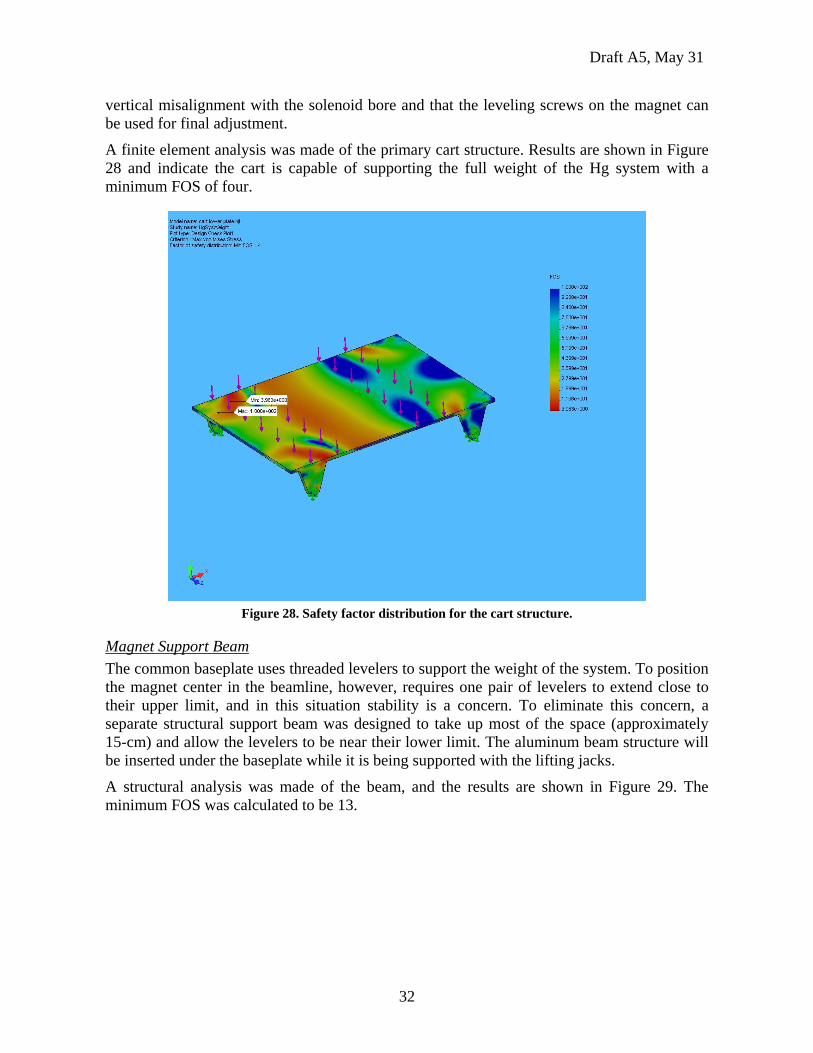
Target Cart This component carries the weight of the Hg delivery system and allows it to transfer from the transporter frame to the common baseplate while inserting the target module into the bore of the solenoid. Primary material is aluminum. The cart incorporates the same lateral position adjustment system as the common baseplate, so the Hg system can be horizontally shifted with the solenoid for precise alignment with the beam. No vertical positioning adjustment is available; it is assumed the flexible components of the target module will accommodate minor
Draft A5, May 31
32
vertical misalignment with the solenoid bore and that the leveling screws on the magnet can be used for final adjustment.
A finite element analysis was made of the primary cart structure. Results are shown in Figure 28 and indicate the cart is capable of supporting the full weight of the Hg system with a minimum FOS of four.
Figure 28. Safety factor distribution for the cart structure.
Magnet Support Beam The common baseplate uses threaded levelers to support the weight of the system. To position the magnet center in the beamline, however, requires one pair of levelers to extend close to their upper limit, and in this situation stability is a concern. To eliminate this concern, a separate structural support beam was designed to take up most of the space (approximately 15-cm) and allow the levelers to be near their lower limit. The aluminum beam structure will be inserted under the baseplate while it is being supported with the lifting jacks.
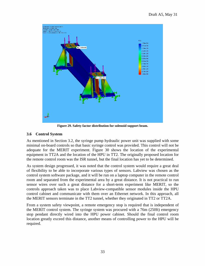
A structural analysis was made of the beam, and the results are shown in Figure 29. The minimum FOS was calculated to be 13.
Draft A5, May 31
33
Figure 29. Safety factor distribution for solenoid support beam.
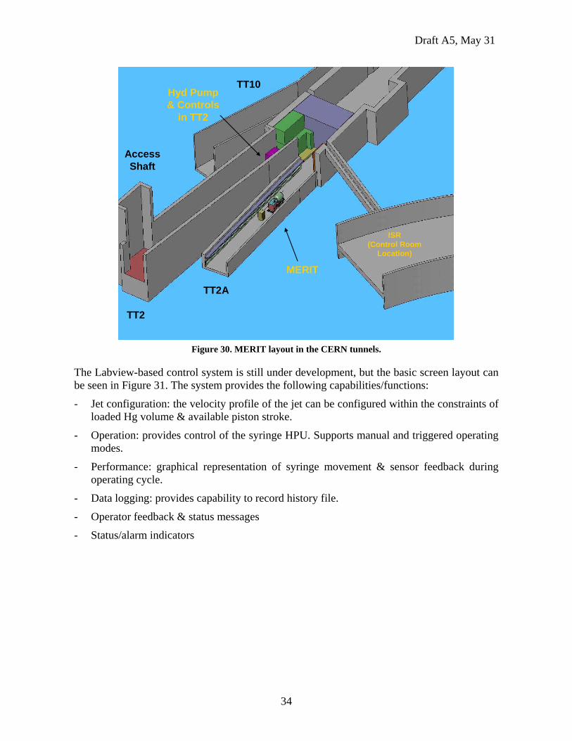
3.6 Control System As mentioned in Section 3.2, the syringe pump hydraulic power unit was supplied with some minimal on-board controls so that basic syringe control was provided. This control will not be adequate for the MERIT experiment. Figure 30 shows the location of the experimental equipment in TT2A and the location of the HPU in TT2. The originally proposed location for the remote control room was the ISR tunnel, but the final location has yet to be determined.
As system design progressed, it was noted that the control system would require a great deal of flexibility to be able to incorporate various types of sensors. Labview was chosen as the control system software package, and it will be run on a laptop computer in the remote control room and separated from the experimental area by a great distance. It is not practical to run sensor wires over such a great distance for a short-term experiment like MERIT, so the controls approach taken was to place Labview-compatible sensor modules inside the HPU control cabinet and communicate with them over an Ethernet network. In this approach, all the MERIT sensors terminate in the TT2 tunnel, whether they originated in TT2 or TT2A.
From a system safety viewpoint, a remote emergency stop is required that is independent of the MERIT control system. The syringe system was procured with a 76m (250ft) emergency stop pendant directly wired into the HPU power cabinet. Should the final control room location greatly exceed this distance, another means of controlling power to the HPU will be required.
Draft A5, May 31
34
TT10
TT2
TT2A
ISR(Control Room
Location)
MERIT
Hyd Pump& Controls
in TT2
AccessShaft
TT10
TT2
TT2A
ISR(Control Room
Location)
MERIT
Hyd Pump& Controls
in TT2
AccessShaft
Figure 30. MERIT layout in the CERN tunnels.
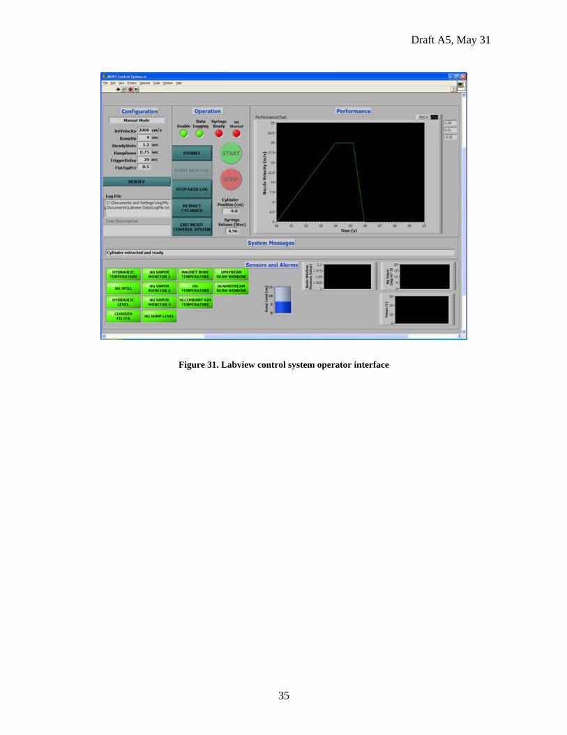
The Labview-based control system is still under development, but the basic screen layout can be seen in Figure 31. The system provides the following capabilities/functions:
- Jet configuration: the velocity profile of the jet can be configured within the constraints of loaded Hg volume & available piston stroke.
- Operation: provides control of the syringe HPU. Supports manual and triggered operating modes.
- Performance: graphical representation of syringe movement & sensor feedback during operating cycle.
- Data logging: provides capability to record history file.
- Operator feedback & status messages
- Status/alarm indicators
Draft A5, May 31
35
Figure 31. Labview control system operator interface
Draft A5, May 31
36
4.0 Operations and Testing
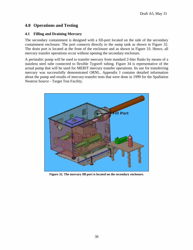
4.1 Filling and Draining Mercury The secondary containment is designed with a fill-port located on the side of the secondary containment enclosure. The port connects directly to the sump tank as shown in Figure 32. The drain port is located at the front of the enclosure and as shown in Figure 33. Hence, all mercury transfer operations occur without opening the secondary enclosure.
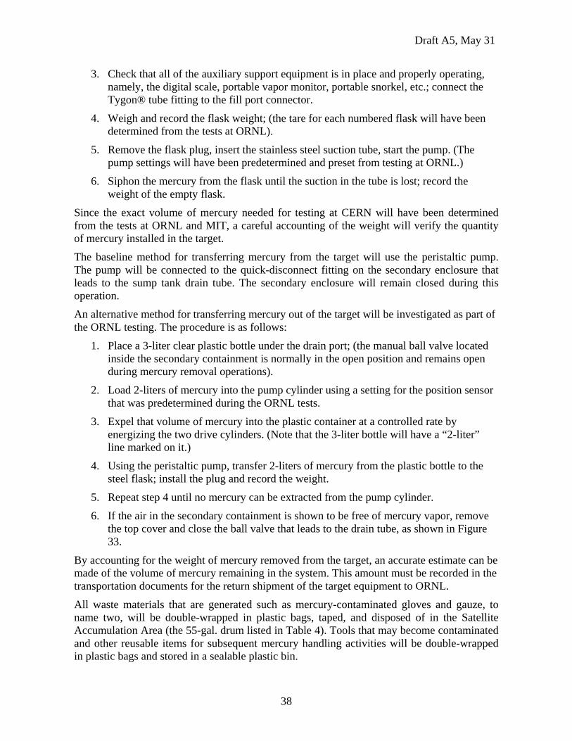
A peristaltic pump will be used to transfer mercury from standard 2-liter flasks by means of a stainless steel tube connected to flexible Tygon® tubing. Figure 34 is representative of the actual pump that will be used for MERIT mercury transfer operations. Its use for transferring mercury was successfully demonstrated ORNL. Appendix I contains detailed information about the pump and results of mercury-transfer tests that were done in 1999 for the Spallation Neutron Source - Target Test Facility.
Figure 32. The mercury fill port is located on the secondary enclosure.
Fill Port
Draft A5, May 31
37
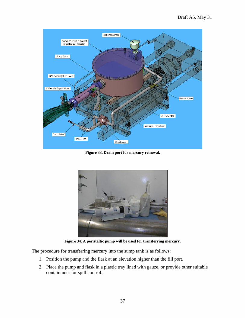
Figure 33. Drain port for mercury removal.
Figure 34. A peristaltic pump will be used for transferring mercury.
The procedure for transferring mercury into the sump tank is as follows:
1. Position the pump and the flask at an elevation higher than the fill port.
2. Place the pump and flask in a plastic tray lined with gauze, or provide other suitable containment for spill control.
Draft A5, May 31
38
3. Check that all of the auxiliary support equipment is in place and properly operating, namely, the digital scale, portable vapor monitor, portable snorkel, etc.; connect the Tygon® tube fitting to the fill port connector.
4. Weigh and record the flask weight; (the tare for each numbered flask will have been determined from the tests at ORNL).
5. Remove the flask plug, insert the stainless steel suction tube, start the pump. (The pump settings will have been predetermined and preset from testing at ORNL.)
6. Siphon the mercury from the flask until the suction in the tube is lost; record the weight of the empty flask.
Since the exact volume of mercury needed for testing at CERN will have been determined from the tests at ORNL and MIT, a careful accounting of the weight will verify the quantity of mercury installed in the target.
The baseline method for transferring mercury from the target will use the peristaltic pump. The pump will be connected to the quick-disconnect fitting on the secondary enclosure that leads to the sump tank drain tube. The secondary enclosure will remain closed during this operation.
An alternative method for transferring mercury out of the target will be investigated as part of the ORNL testing. The procedure is as follows:
1. Place a 3-liter clear plastic bottle under the drain port; (the manual ball valve located inside the secondary containment is normally in the open position and remains open during mercury removal operations).
2. Load 2-liters of mercury into the pump cylinder using a setting for the position sensor that was predetermined during the ORNL tests.
3. Expel that volume of mercury into the plastic container at a controlled rate by energizing the two drive cylinders. (Note that the 3-liter bottle will have a “2-liter” line marked on it.)
4. Using the peristaltic pump, transfer 2-liters of mercury from the plastic bottle to the steel flask; install the plug and record the weight.
5. Repeat step 4 until no mercury can be extracted from the pump cylinder.
6. If the air in the secondary containment is shown to be free of mercury vapor, remove the top cover and close the ball valve that leads to the drain tube, as shown in Figure 33.
By accounting for the weight of mercury removed from the target, an accurate estimate can be made of the volume of mercury remaining in the system. This amount must be recorded in the transportation documents for the return shipment of the target equipment to ORNL.
All waste materials that are generated such as mercury-contaminated gloves and gauze, to name two, will be double-wrapped in plastic bags, taped, and disposed of in the Satellite Accumulation Area (the 55-gal. drum listed in Table 4). Tools that may become contaminated and other reusable items for subsequent mercury handling activities will be double-wrapped in plastic bags and stored in a sealable plastic bin.
Draft A5, May 31
39
4.2 Mercury Vapor Filtration The secondary enclosure has two sulfur-impregnated charcoal filter assemblies; the larger one mounted on the top cover, the smaller one mounted on the down beam wall. These filters are an adaptation of filter used in the portable snorkel. The primary filter on the top cover measures 432 x 255 x 51 mm (17 x 10 x 2 inches) and the secondary filter on the back wall measures 267 x 267 x 38 mm (10-1/2 x 10-1/2 x 1-1/2 inches). Figure 1 shows the location of the filters. Each filter is designed to connect with the 5-inch (127-mm) diameter hose of the portable snorkel.
During routine target equipment operations each filter port remains closed so that there no exchange of the air environment between the secondary enclosure and the TT2A Tunnel. The two air environments are at pressure equilibrium as long as the temperature in the enclosure remains approximately at the temperature in the tunnel. (The temperature rise of the mercury and the air in the enclosure will be recorded between pulses during the ORNL tests.) Therefore, the air in the secondary enclosure that is under continuous monitoring for mercury vapor is isolated from the tunnel air.
Prior to installing mercury into the sump tank, the cover on the primary filter will be removed and the volume of air that is displaced from the sump tank will be “pushed” through the primary filter, and monitored for mercury vapor levels using the portable vapor monitor. If any vapor is detected, the snorkel can be attached to provide a double level of filtration to prevent mercury vapor from being pushed into the tunnel environment. The effectiveness of “single” and “double” filtration will be demonstrated as part of the testing at ORNL.
Filter Lifetime Estimate An estimate of filter lifetime was made based on the calculations used for ORNL’s Target Test Facility and the data provided by the manufacturer of the filter material. The sample calculation shown below yields a lifetime of 185 hours of vapor exposure before the filter is 12% saturated.
- Flow Rate 110 cfm (through the snorkel filter)
- Temperature 25° C (vapor temperature)
- Filter Efficiency 99.0% (vendor information)
- Filter Weight 6 lbs (80% charcoal, 20% sulfur)
- Allowable Filter Saturation 12% (vendor information)
- Filter Life 185 hrs
(Note: The calculation does not include the reduction for adsorption of humidity.)
The following equations were used for the calculation. [5]
Saturation Pressure
(bar) 9294.4/5.3105log 0 +−=
Ksat TP
Draft A5, May 31
40
Saturation Concentration
Filter Replacement Procedure If it becomes necessary to replace either the primary filter or the secondary filter, the portable snorkel will be used to maintain a negative pressure in the secondary enclosure, while at the same time filtering the extracted air. The procedure for replacing the primary filter is described below for a routine operation where the secondary enclosure vapor monitor shows no indication of vapors. The actual procedure will be demonstrated as part of the testing at ORNL.
1. The operator will be dressed with proper personal protection equipment (PPE); the assistant operator will handle the portable vapor monitor.
2. Connect the snorkel hose to the secondary filter port; turn on the snorkel to achieve a low flow rate, i.e., 5-10 cu. ft. per minute (280 liters/min.)
3. Remove the 5-inch diameter cover from the primary filter to permit an inflow of air into the secondary enclosure.
4. Remove the filter pack assembly and increase the snorkel flow rate to a level to be determined during ORNL testing; continue monitoring for vapor in the vicinity of the filter. Place the filter in a plastic bag and seal the bag.
5. Install a new filter; decrease the flow to the snorkel to zero and cover the primary port.
The same procedure will be used for replacing the secondary filter except in step 2, the snorkel hose will be connected to the primary filter port.
4.3 Off-Normal Conditions There are two off-normal conditions for the scope of operations for the target system: the first is measurable vapor in the secondary enclosure, the second is a spill from the primary enclosure into the secondary enclosure, and contained in the secondary.
Vapor Leak Into Secondary Containment The secondary containment is continuously monitored for mercury vapor. A Jerome 431-X monitor located in the adjacent tunnel (TT2) samples the containment volume every 5 minutes. Through its interface with the Lab View® control system, it will send a visual and audible signal if the threshold limit for vapor has been reached. The system will be configured to match the setting used for the Target Test Facility (0.0125 mg/m3), and can easily be changed to meet other levels. The following threshold limits are the current U.S. and ORNL standards.
-OSHA allowable limit: 0.050 mg/m3 for up to a 10 hour work day, 40 hours per week
-ORNL limit: 0.025 mg/m3
-TTF limit: 0.0125 mg/m3
)( )/m(Kg /445.2 3Hg0 mbarsatP
Ksatsat TPC =
Draft A5, May 31
41
Upon receiving a signal (at the TTF limit), the operator will check the conductivity probe sensor for indications of a major leak from the primary containment, the secondary vapor monitor in the tunnel. It there is a zero-reading from the conductivity probe, and the other sensors including the secondary vapor monitor are sending normal signals, it may be concluded that: 1) there is a minor leak from the primary containment, or 2) the vapor monitor sent a false-positive signal.
To verify if the monitor is functioning properly, the spare (portable) sensor will be exchanged with the monitor in tunnel TT2, where immediate personnel access is possible. Regardless of the outcome of the monitor test, operations may continue until the end of a shift. At that time, a decision will be made to make a visual inspection of the system. According to Table 3, the dose rate at the top of the secondary enclosure, at shutdown (or immediately thereafter) will be <1 mrem/h, and will be low enough for visual inspection.
While this is happening the vapor monitor located in the tunnel near the target equipment will be checked for indications of vapor in the vicinity. If vapor is present in the secondary enclosure it will remain contained unless there is a break in the enclosure, or leakage from one or both of the enclosure filters. The portable monitor will be used to check for any of these possible occurrences if vapor is detected in the tunnel.
Mercury Leak Into Secondary Containment Although highly unlikely, if elemental mercury is detected in the secondary enclosure by the conductivity probe or by visual inspection, there will be no doubt that the integrity of the primary containment was breached. Based on the operations requirement that the primary containment shall not be opened during the lifetime of the experiment at CERN, test operations will cease and a cool down period of up to one month will commence. According to Table 3, the mercury after that cool down period will have a contact dose of <10-2 mSv/h (<1 mrem/h), low enough to extract Hg from the target and refill the mercury flasks.
The target, being a double contained system is designed to that unloading mercury can be accomplished without opening the secondary containment. Hence, the vapor will remain contained as long as the secondary enclosure is not opened. The (activated) mercury will be removed from the syringe pump system in the same manner described in Section 4.1, with the exception that Health Physics surveillance and oversight will be required because of the activation of the mercury.
4.4 Equipment for Mercury Handling
A kit consisting of miscellaneous small tools, cleanup materials, various plastic containers, and personal protection equipment (PPE), will travel with the target system to MIT and CERN. The kit will provide self-sufficiency for all activities that deal with the target equipment and mercury handling, including installation, equipment check out, spill control, and cleanup. Table 6 is a listing of the equipment that will be available for use to support target operations.
Table 6. Miscellaneous Experiment Support Equipment.
Item Comments Vacuum Cleaner - Tiger Vac® At Princeton; will be sent to MIT Portable Snorkel - Scavenger® At Princeton; will be sent to ORNL
Draft A5, May 31
42
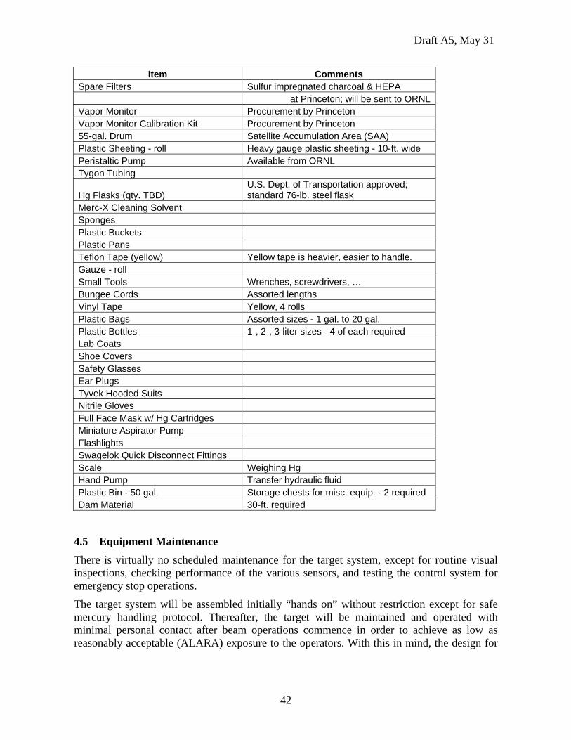
Item Comments Spare Filters Sulfur impregnated charcoal & HEPA at Princeton; will be sent to ORNL Vapor Monitor Procurement by Princeton Vapor Monitor Calibration Kit Procurement by Princeton 55-gal. Drum Satellite Accumulation Area (SAA) Plastic Sheeting - roll Heavy gauge plastic sheeting - 10-ft. wide Peristaltic Pump Available from ORNL Tygon Tubing
Hg Flasks (qty. TBD) U.S. Dept. of Transportation approved; standard 76-lb. steel flask
Merc-X Cleaning Solvent Sponges Plastic Buckets Plastic Pans Teflon Tape (yellow) Yellow tape is heavier, easier to handle. Gauze - roll Small Tools Wrenches, screwdrivers, … Bungee Cords Assorted lengths Vinyl Tape Yellow, 4 rolls Plastic Bags Assorted sizes - 1 gal. to 20 gal. Plastic Bottles 1-, 2-, 3-liter sizes - 4 of each required Lab Coats Shoe Covers Safety Glasses Ear Plugs Tyvek Hooded Suits Nitrile Gloves Full Face Mask w/ Hg Cartridges Miniature Aspirator Pump Flashlights Swagelok Quick Disconnect Fittings Scale Weighing Hg Hand Pump Transfer hydraulic fluid Plastic Bin - 50 gal. Storage chests for misc. equip. - 2 required Dam Material 30-ft. required
4.5 Equipment Maintenance There is virtually no scheduled maintenance for the target system, except for routine visual inspections, checking performance of the various sensors, and testing the control system for emergency stop operations.
The target system will be assembled initially “hands on” without restriction except for safe mercury handling protocol. Thereafter, the target will be maintained and operated with minimal personal contact after beam operations commence in order to achieve as low as reasonably acceptable (ALARA) exposure to the operators. With this in mind, the design for

Draft A5, May 31
43
the target system incorporated the use of dripless quick-disconnect connections, and fasteners and hardware suitable for minimizing handling time and the need for subsequent maintenance.
Draft A5, May 31
44
5.0 Facility Interfaces
5.1 Electrical The hydraulic pump motor will require 480 VAC, 3-phase, 60 Hz for operation at MIT and 360 VAC, 3-phase, 50 Hz for operation at CERN. In addition, the power source will require a means to be remotely de-energized should an emergency occur.
5.2 Ethernet
Hg system control requires network wiring between the remote control room and the hydraulic power unit in the TT2A tunnel. A dedicated network is preferred, but access using CERN's standard network is also acceptable if that is permitted by CERN network policies.
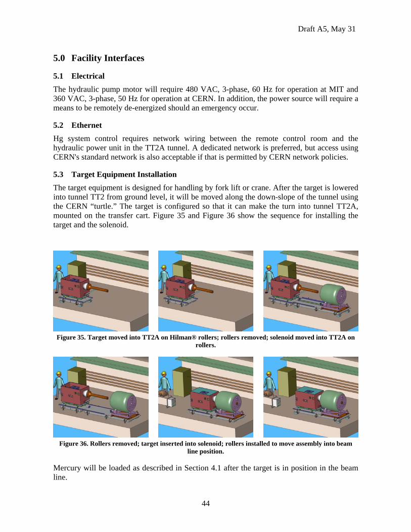
5.3 Target Equipment Installation The target equipment is designed for handling by fork lift or crane. After the target is lowered into tunnel TT2 from ground level, it will be moved along the down-slope of the tunnel using the CERN “turtle.” The target is configured so that it can make the turn into tunnel TT2A, mounted on the transfer cart. Figure 35 and Figure 36 show the sequence for installing the target and the solenoid.
Figure 35. Target moved into TT2A on Hilman® rollers; rollers removed; solenoid moved into TT2A on
rollers.
Figure 36. Rollers removed; target inserted into solenoid; rollers installed to move assembly into beam
line position.
Mercury will be loaded as described in Section 4.1 after the target is in position in the beam line.
Draft A5, May 31
45
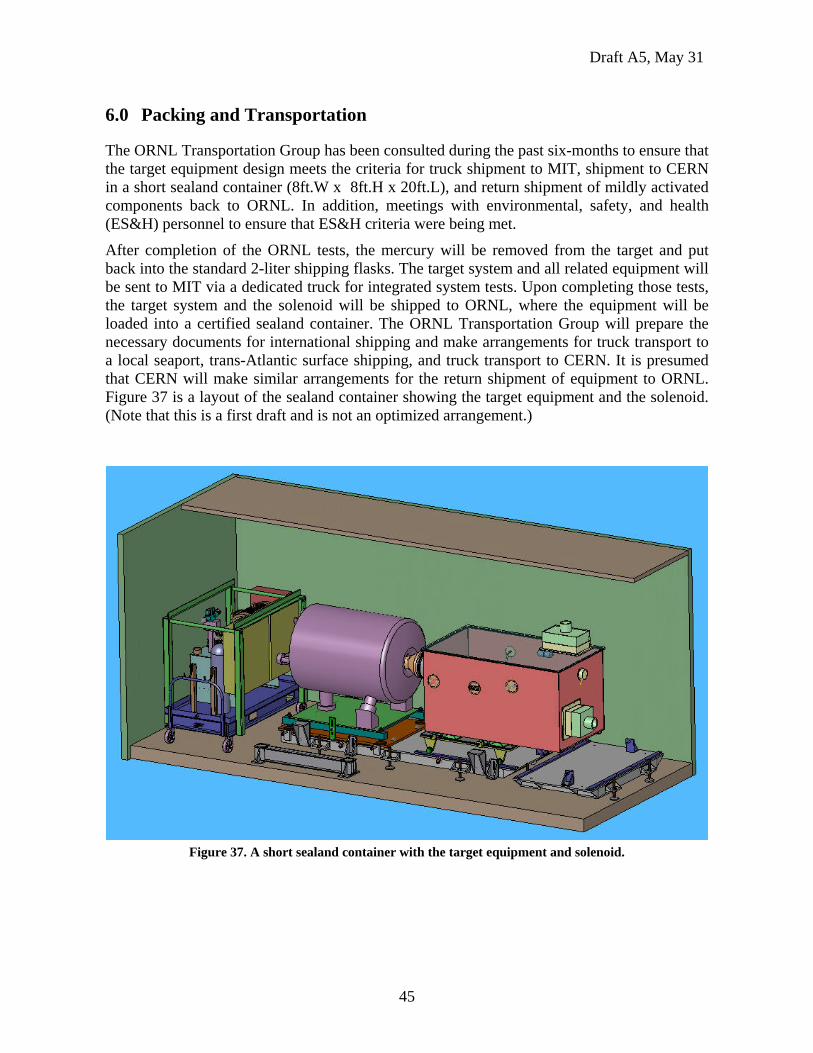
6.0 Packing and Transportation
The ORNL Transportation Group has been consulted during the past six-months to ensure that the target equipment design meets the criteria for truck shipment to MIT, shipment to CERN in a short sealand container (8ft.W x 8ft.H x 20ft.L), and return shipment of mildly activated components back to ORNL. In addition, meetings with environmental, safety, and health (ES&H) personnel to ensure that ES&H criteria were being met.
After completion of the ORNL tests, the mercury will be removed from the target and put back into the standard 2-liter shipping flasks. The target system and all related equipment will be sent to MIT via a dedicated truck for integrated system tests. Upon completing those tests, the target system and the solenoid will be shipped to ORNL, where the equipment will be loaded into a certified sealand container. The ORNL Transportation Group will prepare the necessary documents for international shipping and make arrangements for truck transport to a local seaport, trans-Atlantic surface shipping, and truck transport to CERN. It is presumed that CERN will make similar arrangements for the return shipment of equipment to ORNL. Figure 37 is a layout of the sealand container showing the target equipment and the solenoid. (Note that this is a first draft and is not an optimized arrangement.)
Figure 37. A short sealand container with the target equipment and solenoid.
Draft A5, May 31
46
7.0 Equipment Decommissioning and Disposition
After completing the testing at CERN, it is presumed that the target/solenoid equipment will remain undisturbed for several weeks so that the inventory of mercury will cool to a dose rate approaching <10-2 mSv/h (1.0 mrem/h). The mercury will then be removed from the target and stored in steel flasks. Then, the target/solenoid will be moved out of the beam line and left in tunnel TT2A for additional time. After another 2-4 weeks, virtually all components will have a dose rate that is low enough (10-4 mSv/h — 0.01 mrem/h), to permit unlimited handling for radiation-trained workers.
At that time, the target can be removed from the solenoid, and all equipment can be brought to ground level for placement into the sealand container. The original packing materials and crates will be reused, and presumably the CERN Transportation Group will make arrangements for the return shipment to ORNL.
Draft A5, May 31
47
8.0 References
1. “MERIT Experiment Window Study – Proton Beam Windows – Optical Windows,” N. Simos – Brookhaven National Laboratory; presented at the BNL Collaboration Meeting, December 12, 2005.
2. “Solenoid Field Map.txt,” H. Kirk – Brookhaven National Laboratory; September 21, 2004.
3. “MARS Simulation of the Mercury Target Experiment,” Sergei Striganov - Fermi National Laboratory; presented at the MIT Collaboration Meeting, October 18, 2005.
4. “Sapphire Window Impact Test,” K. McDonald, H.-J. Park, Princeton University, January 26, 2006. http://www.hep.princeton.edu/~mcdonald/mumu/target/
5. Quechsilber und seine Gefahren, Swiss government worker safety report, SBA No. 145, Luzern.