Embed Size (px)
Citation preview
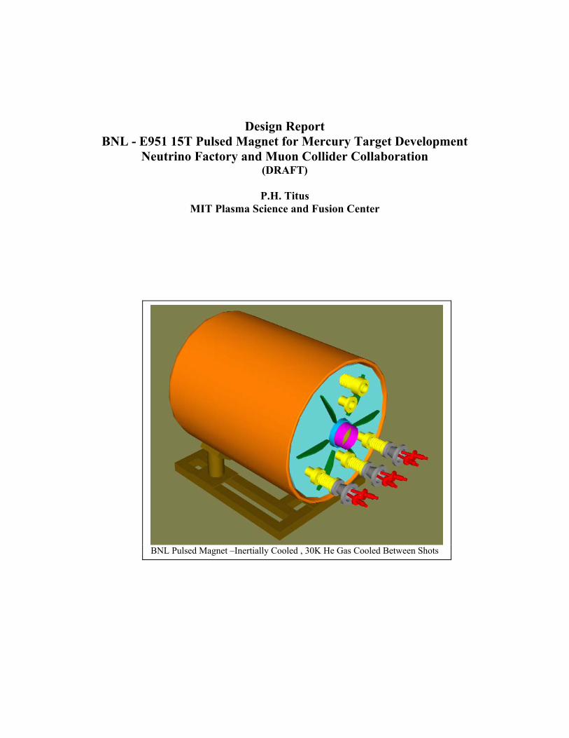
Design Report BNL - E951 15T Pulsed Magnet for Mercury Target Development
Neutrino Factory and Muon Collider Collaboration (DRAFT)
P.H. Titus
MIT Plasma Science and Fusion Center
BNL Pulsed Magnet –Inertially Cooled , 30K He Gas Cooled Between Shots
Table of Contents Introduction 1.0 Design Input/Specifications 2.0 References 3.0 Structural Design Criteria 4.0 Conductor and Insulation Systems Design 5.0 Coil Lorentz Force Stress Analysis 6.0 Nominal – Three Segment Analysis Optional – Two Segment Analysis Elastic Plastic Analysis of Inner Segment
Mandrel Coil Heat-Up and Thermal Stress 7.0 Break-outs, Leads and Penetrations 8.0 Cryogenic Electrical Break 9.0 He/Vacuum/LN2 can pressure design. 10.0 Vacuum Jacket Buckling 11.0 Bellows Design 12.0 Eddy Currents, Loads and Stresses in Vacuum and He Can 13.0 Steady State Heat Gain. 14.0 Cooldown between shots 15.0
Temperature profile, and time-temperature calculations Pressure drop calculations
Instrumentation 16.0 Support Frame 17.0 Manufacturing/Assembly Approaches 18.0 Winding Procedures Phased Construction requirements Safety, and Failure Analyses 19.0 Cost Studies 20.0
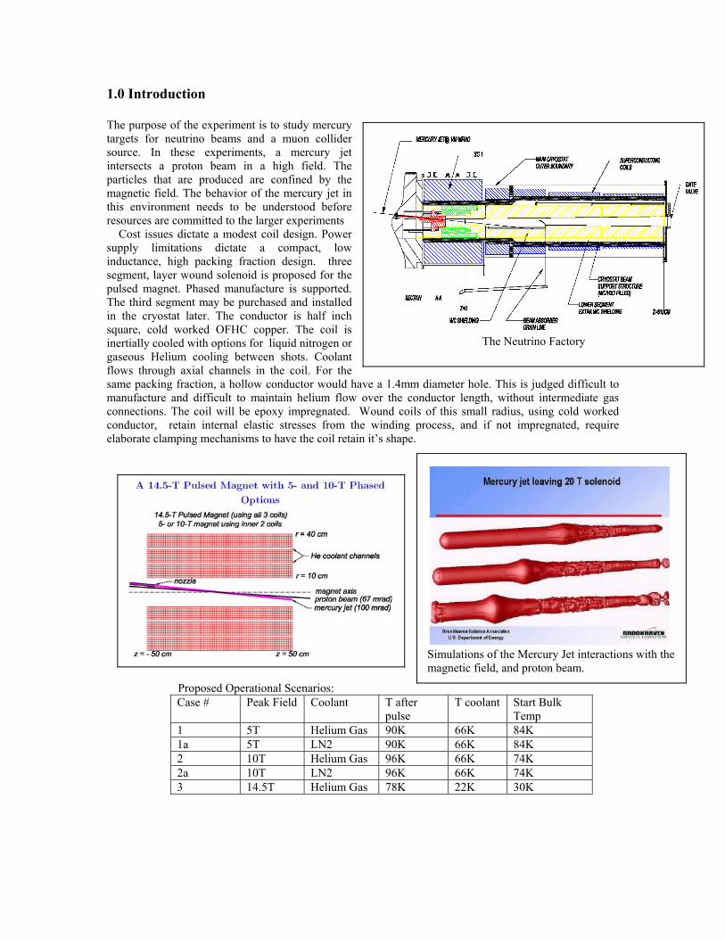
1.0 Introduction The purpose of the experiment is to study mercury targets for neutrino beams and a muon collider source. In these experiments, a mercury jet intersects a proton beam in a high field. The particles that are produced are confined by the magnetic field. The behavior of the mercury jet in this environment needs to be understood before resources are committed to the larger experiments Cost issues dictate a modest coil design. Power supply limitations dictate a compact, low inductance, high packing fraction design. three segment, layer wound solenoid is proposed for the pulsed magnet. Phased manufacture is supported. The third segment may be purchased and installed in the cryostat later. The conductor is half inch square, cold worked OFHC copper. The coil is inertially cooled with options for liquid nitrogen or gaseous Helium cooling between shots. Coolant flows through axial channels in the coil. For the same packing fraction, a hollow conductor would have a 1.4mm diameter hole. This is judged difficult to manufacture and difficult to maintain helium flow over the conductor length, without intermediate gas connections. The coil will be epoxy impregnated. Wound coils of this small radius, using cold worked conductor, retain internal elastic stresses from the winding process, and if not impregnated, require elaborate clamping mechanisms to have the coil retain it’s shape.
Proposed Operational Scenarios:
The Neutrino Factory
Simulations of the Mercury Jet interactions with the magnetic field, and proton beam.
Case # Peak Field Coolant T after pulse
T coolant Start Bulk Temp
1 5T Helium Gas 90K 66K 84K 1a 5T LN2 90K 66K 84K 2 10T Helium Gas 96K 66K 74K 2a 10T LN2 96K 66K 74K 3 14.5T Helium Gas 78K 22K 30K
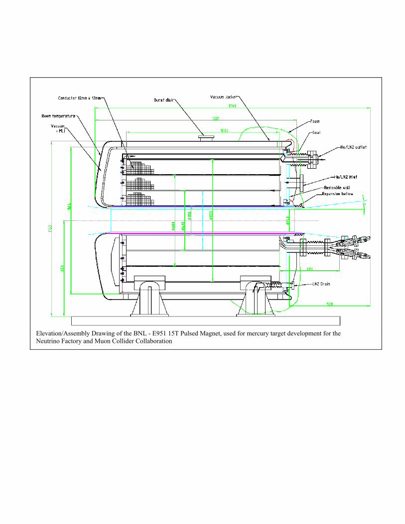
Elevation/Assembly Drawing of the BNL - E951 15T Pulsed Magnet, used for mercury target development for the Neutrino Factory and Muon Collider Collaboration
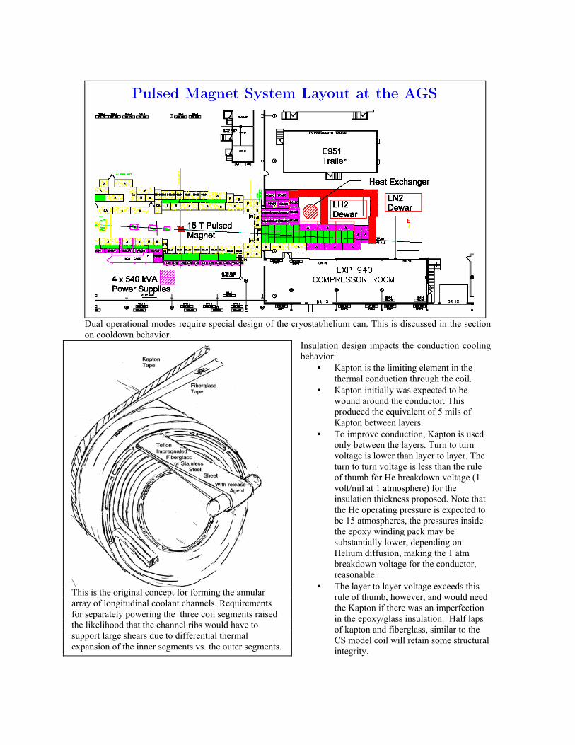
Dual operational modes require special design of the cryostat/helium can. This is discussed in the section on cooldown behavior.
Insulation design impacts the conduction cooling behavior:
• Kapton is the limiting element in the thermal conduction through the coil.
• Kapton initially was expected to be wound around the conductor. This produced the equivalent of 5 mils of Kapton between layers.
• To improve conduction, Kapton is used only between the layers. Turn to turn voltage is lower than layer to layer. The turn to turn voltage is less than the rule of thumb for He breakdown voltage (1 volt/mil at 1 atmosphere) for the insulation thickness proposed. Note that the He operating pressure is expected to be 15 atmospheres, the pressures inside the epoxy winding pack may be substantially lower, depending on Helium diffusion, making the 1 atm breakdown voltage for the conductor, reasonable.
• The layer to layer voltage exceeds this rule of thumb, however, and would need the Kapton if there was an imperfection in the epoxy/glass insulation. Half laps of kapton and fiberglass, similar to the CS model coil will retain some structural integrity.
This is the original concept for forming the annular array of longitudinal coolant channels. Requirements for separately powering the three coil segments raised the likelihood that the channel ribs would have to support large shears due to differential thermal expansion of the inner segments vs. the outer segments.
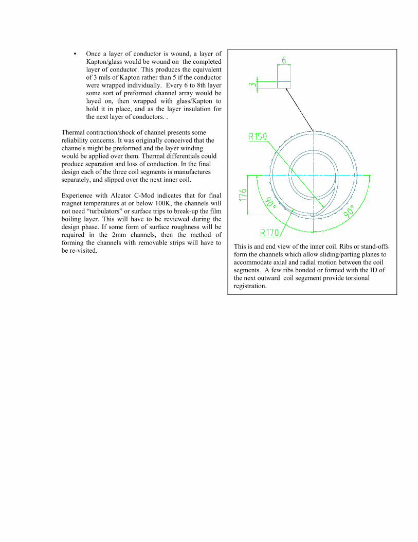
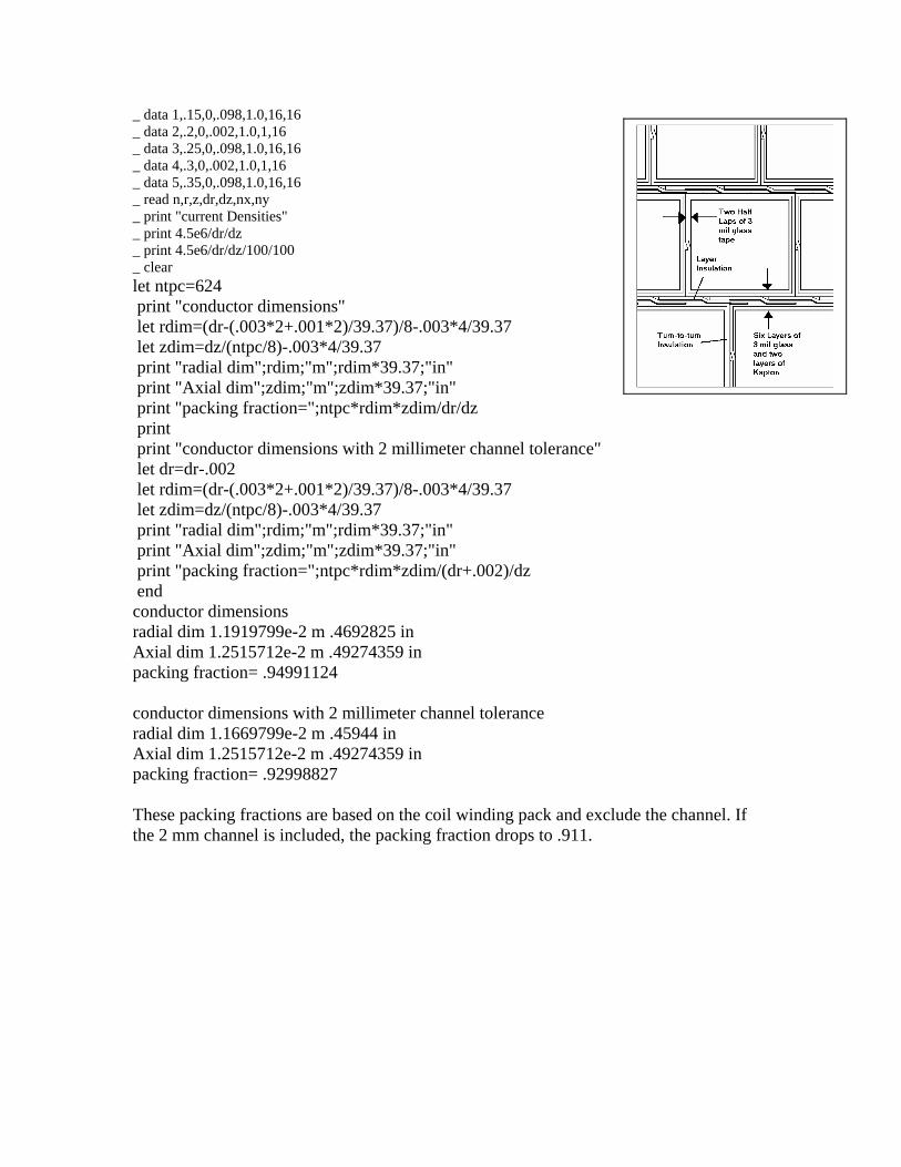
• Once a layer of conductor is wound, a layer of Kapton/glass would be wound on the completed layer of conductor. This produces the equivalent of 3 mils of Kapton rather than 5 if the conductor were wrapped individually. Every 6 to 8th layer some sort of preformed channel array would be layed on, then wrapped with glass/Kapton to hold it in place, and as the layer insulation for the next layer of conductors. .
This is and end view of the inner coil. Ribs or stand-offs form the channels which allow sliding/parting planes to accommodate axial and radial motion between the coil segments. A few ribs bonded or formed with the ID of the next outward coil segement provide torsional registration.
Thermal contraction/shock of channel presents some reliability concerns. It was originally conceived that the channels might be preformed and the layer winding would be applied over them. Thermal differentials could produce separation and loss of conduction. In the final design each of the three coil segments is manufactures separately, and slipped over the next inner coil. Experience with Alcator C-Mod indicates that for final magnet temperatures at or below 100K, the channels will not need “turbulators” or surface trips to break-up the film boiling layer. This will have to be reviewed during the design phase. If some form of surface roughness will be required in the 2mm channels, then the method of forming the channels with removable strips will have to be re-visited.
2.0 Design Input/Specifications
It is important that we have the expected (design) operating conditions for, especially, the following parameters:
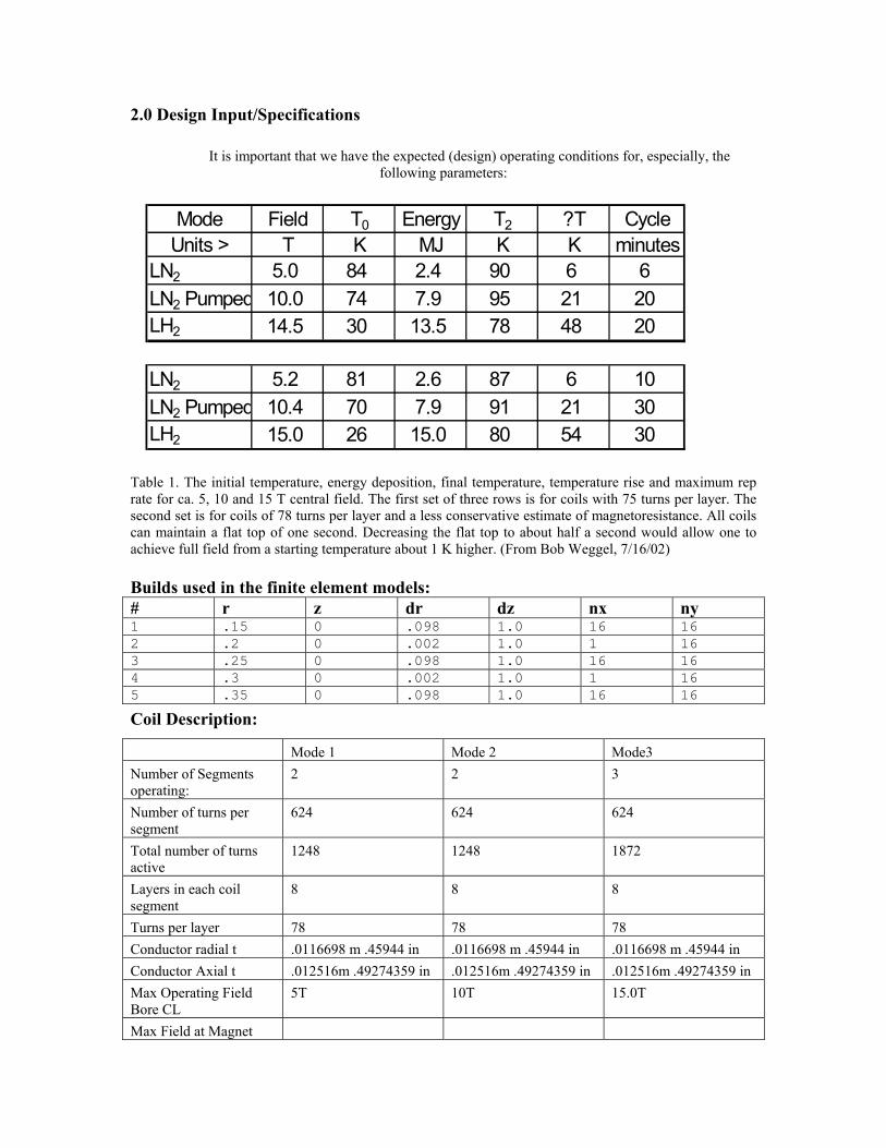
Mode Field T0 Energy T2 ?T CycleUnits > T K MJ K K minutes
LN2 5.0 84 2.4 90 6 6LN2 Pumped 10.0 74 7.9 95 21 20LH2 14.5 30 13.5 78 48 20
LN2 5.2 81 2.6 87 6 10LN2 Pumped 10.4 70 7.9 91 21 30LH2 15.0 26 15.0 80 54 30
Table 1. The initial temperature, energy deposition, final temperature, temperature rise and maximum rep rate for ca. 5, 10 and 15 T central field. The first set of three rows is for coils with 75 turns per layer. The second set is for coils of 78 turns per layer and a less conservative estimate of magnetoresistance. All coils can maintain a flat top of one second. Decreasing the flat top to about half a second would allow one to achieve full field from a starting temperature about 1 K higher. (From Bob Weggel, 7/16/02) Builds used in the finite element models: # r z dr dz nx ny 1 .15 0 .098 1.0 16 162 .2 0 .002 1.0 1 163 .25 0 .098 1.0 16 164 .3 0 .002 1.0 1 165 .35 0 .098 1.0 16 16
Coil Description:
Mode 1 Mode 2 Mode3 Number of Segments operating:
2 2 3
Number of turns per segment
624 624 624
Total number of turns active
1248 1248 1872
Layers in each coil segment
8 8 8
Turns per layer 78 78 78 Conductor radial t .0116698 m .45944 in .0116698 m .45944 in .0116698 m .45944 in Conductor Axial t .012516m .49274359 in .012516m .49274359 in .012516m .49274359 in Max Operating Field Bore CL
5T 10T 15.0T
Max Field at Magnet
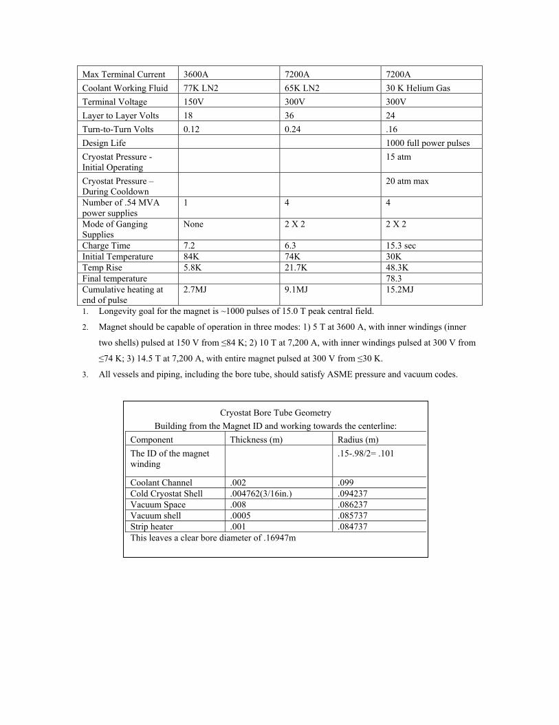
Max Terminal Current 3600A 7200A 7200A Coolant Working Fluid 77K LN2 65K LN2 30 K Helium Gas Terminal Voltage 150V 300V 300V Layer to Layer Volts 18 36 24 Turn-to-Turn Volts 0.12 0.24 .16 Design Life 1000 full power pulses Cryostat Pressure -Initial Operating
15 atm
Cryostat Pressure – During Cooldown
20 atm max
Number of .54 MVA power supplies
1 4 4
Mode of Ganging Supplies
None 2 X 2 2 X 2
Charge Time 7.2 6.3 15.3 sec Initial Temperature 84K 74K 30K Temp Rise 5.8K 21.7K 48.3K Final temperature 78.3 Cumulative heating at end of pulse
2.7MJ 9.1MJ 15.2MJ
1. Longevity goal for the magnet is ~1000 pulses of 15.0 T peak central field.
2. Magnet should be capable of operation in three modes: 1) 5 T at 3600 A, with inner windings (inner
two shells) pulsed at 150 V from ≤84 K; 2) 10 T at 7,200 A, with inner windings pulsed at 300 V from
≤74 K; 3) 14.5 T at 7,200 A, with entire magnet pulsed at 300 V from ≤30 K.
3. All vessels and piping, including the bore tube, should satisfy ASME pressure and vacuum codes.
Cryostat Bore Tube Geometry Building from the Magnet ID and working towards the centerline:
Component Thickness (m) Radius (m) The ID of the magnet winding
.15-.98/2= .101
Coolant Channel .002 .099 Cold Cryostat Shell .004762(3/16in.) .094237 Vacuum Space .008 .086237 Vacuum shell .0005 .085737 Strip heater .001 .084737 This leaves a clear bore diameter of .16947m
3.0 References [1] Fusion Ignition Research Experiment Structural Design Criteria; Doc. No. 11_FIRE_-DesCrit_IZ_022499.doc; February, 1999 [2] "General Electric Design and Manufacture of a Test Coil for the LCP", 8th Symposium on Engineering Problems of Fusion Research, Vol III, Nov 1979 [3] Product Literature, Inco Alloys International, Inc Huntington West Virginia 25720, USA [4] "Mechanical, Electrical and Thermal Characterization of G10CR and G11CR Glass Cloth/Epoxy Laminates Between Room Temperature and 4 deg. K", M.B. Kasen et al , National Bureau of Standards, Boulder Colorado. [5 ] "US ITER Insulation Irradiation Report Program Final Report" August 31 1995 Reed, Fabian, Shultz [6] Effect of Face Compression on Interlaminar Shear Strength of Polyimide/S2 Glass Laminate Insulators - Preliminary Report" H.Becker, T. Cookson (GDC) June 24 1985 [7] "Shear Compression Tests for ITER Magnet Insulation" Simon, Drexler, Reed, Advances in Cryogenic Engineering Materials Vol 40 (1994) [8] "Case Studies in Superconducting Magnets" Design and operational Issues, by Yukikazu Iwasa , Plenum Press, New York and London 1994 [9] CryoCoat™ UltraLight™ Insulation presented by:Michael L. Tupper COMPOSITE TECHNOLOGY DEVELOMENT INC. 1505 Coal Creek Drive Lafayette, Colorado 80026 January 2001 [10] http://www.lakeshore.com/temp/sen/crtd.html [11] CPC Cryolab Vacuum Tight Pressure Relief Discs PR-3 Series Data Sheet [12] Mark’s Standard Handbook for Engineers, Sevnth Edition, Pages 3-60 through 3-63, Pipe friction factors and entry/exit losses. [13] Air Liquide Web Site http://www.airliquide.com - For some Helium and Nitrogen Properties [14] MLI Specification from: “LHC Interaction Region Quadrupole Cryostat”, Thomas H. Nicol, Fermi National Accelerator Laboratory December 3, 1998, P.O. Box 500, Batavia, IL 60510
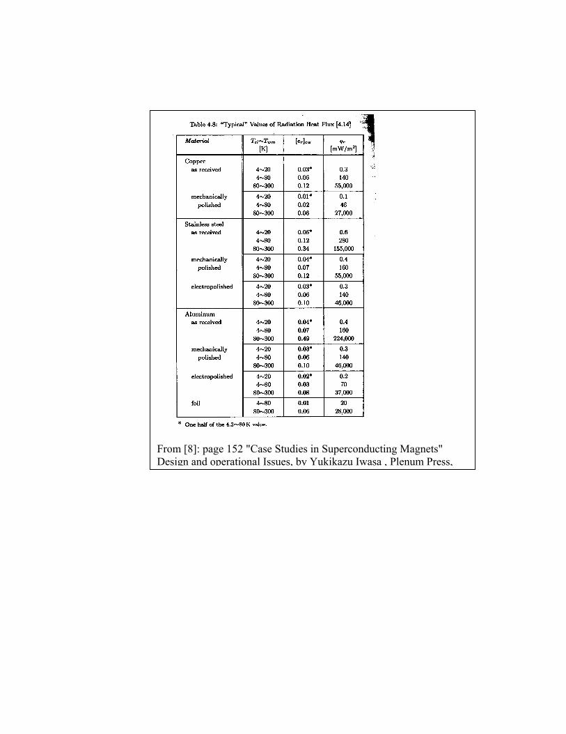
From [8]: page 152 "Case Studies in Superconducting Magnets" Design and operational Issues, by Yukikazu Iwasa , Plenum Press,
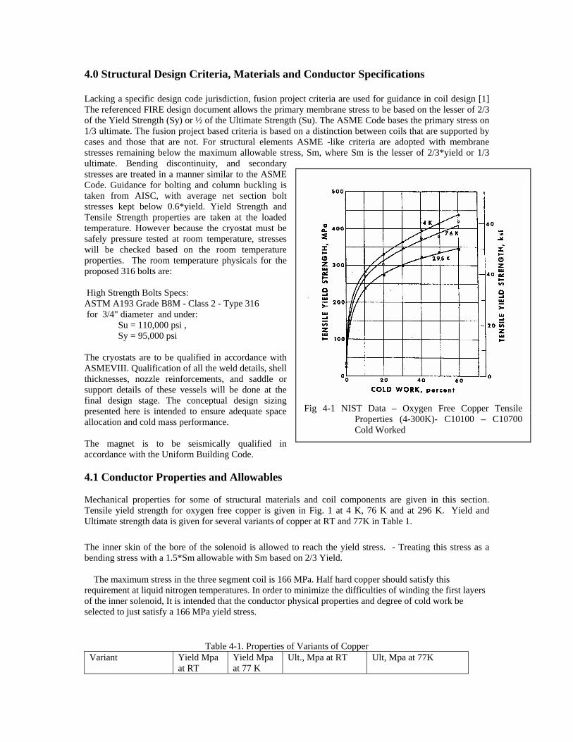
4.0 Structural Design Criteria, Materials and Conductor Specifications Lacking a specific design code jurisdiction, fusion project criteria are used for guidance in coil design [1] The referenced FIRE design document allows the primary membrane stress to be based on the lesser of 2/3 of the Yield Strength (Sy) or ½ of the Ultimate Strength (Su). The ASME Code bases the primary stress on 1/3 ultimate. The fusion project based criteria is based on a distinction between coils that are supported by cases and those that are not. For structural elements ASME -like criteria are adopted with membrane stresses remaining below the maximum allowable stress, Sm, where Sm is the lesser of 2/3*yield or 1/3 ultimate. Bending discontinuity, and secondary stresses are treated in a manner similar to the ASME Code. Guidance for bolting and column buckling is taken from AISC, with average net section bolt stresses kept below 0.6*yield. Yield Strength and Tensile Strength properties are taken at the loaded temperature. However because the cryostat must be safely pressure tested at room temperature, stresses will be checked based on the room temperature properties. The room temperature physicals for the proposed 316 bolts are: High Strength Bolts Specs: ASTM A193 Grade B8M - Class 2 - Type 316 for 3/4" diameter and under:
Su = 110,000 psi , Sy = 95,000 psi
The cryostats are to be qualified in accordance with ASMEVIII. Qualification of all the weld details, shell thicknesses, nozzle reinforcements, and saddle or support details of these vessels will be done at the final design stage. The conceptual design sizing presented here is intended to ensure adequate space allocation and cold mass performance. The magnet is to be seismically qualified in accordance with the Uniform Building Code. 4.1 Conductor Properties and Allowables Mechanical properties for some of structural materials and coil components are given in this section. Tensile yield strength for oxygen free copper is given in Fig. 1 at 4 K, 76 K and at 296 K. Yield and Ultimate strength data is given for several variants of copper at RT and 77K in Table 1. The inner skin of the bore of the solenoid is allowed to reach the yield stress. - Treating this stress as a bending stress with a 1.5*Sm allowable with Sm based on 2/3 Yield. The maximum stress in the three segment coil is 166 MPa. Half hard copper should satisfy this requirement at liquid nitrogen temperatures. In order to minimize the difficulties of winding the first layers of the inner solenoid, It is intended that the conductor physical properties and degree of cold work be selected to just satisfy a 166 MPa yield stress.
Table 4-1. Properties of Variants of Copper
Variant Yield Mpa at RT
Yield Mpa at 77 K
Ult., Mpa at RT Ult, Mpa at 77K
Fig 4-1 NIST Data – Oxygen Free Copper Tensile
Properties (4-300K)- C10100 – C10700 Cold Worked
C10100/C10700 80%CW
380 420 500
C10100 Becker/C-Mod 60%CW
308 373 350 474
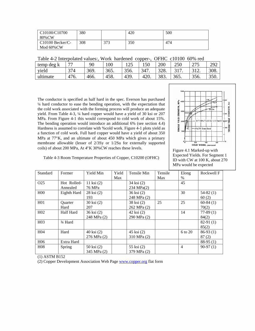
Table 4-2 Interpolated values:, Work hardened copper-, OFHC c10100 60% red temp deg k 77 90 100 125 150 200 250 275 292yield 374 369. 365. 356. 347. 328. 317. 312. 308.ultimate 476. 466. 458. 439. 420. 383. 365. 356. 350. The conductor is specified as half hard in the spec. Everson has purchased ¼ hard conductor to ease the bending operation, with the expectation that the cold work associated with the forming process will produce an adequate yield. From Table 4-3, ¼ hard copper would have a yield of 30 ksi or 207 MPa. From Figure 4-1 this would correspond to cold work of about 15%. The bending operation would introduce an additional 6% (see section 4.4) Hardness is assumed to correlate with %cold work. Figure 4-1 plots yield as a function of cold work. Full hard copper would have a yield of about 350 MPa at 77°K, and an ultimate of about 450 MPa which gives a primary membrane allowable (lesser of 2/3Sy or 1/2Su for externally supported coils) of about 200 MPa, At 4°K 30%CW reaches these levels.
Table 4-3 Room Temperature Properties of Copper, C10200 (OFHC)
Standard Former Yield Min Yield Max
Tensile Min Tensile Max
Elong %
Rockwell F
O25 Hot Rolled-Annealed
11 ksi (2) 76 MPa
34 ksi (2) 234 MPa(2)
45
H00 Eighth Hard 28 ksi (2) 193
36 ksi (2) 248 MPa (2)
30 54-82 (1) 60 (2)
H01 Quarter Hard
30 ksi (2) 207
38 ksi (2) 262 MPa (2)
25 25 60-84 (1) 70(2)
H02 Half Hard 36 ksi (2) 248 MPa (2)
42 ksi (2) 290 MPa (2)
14 77-89 (1) 84(2)
H03 ¾ Hard 82-91 (1) 85(2)
H04 Hard 40 ksi (2) 276 MPa (2)
45 ksi (2) 310 MPa (2)
6 to 20 86-93 (1) 87 (2)
H06 Extra Hard 88-95 (1) H08 Spring 50 ksi (2)
345 MPa (2) 55 ksi (2)
379 MPa (2) 4 90-97 (1)
Figure 4.1 Marked-up with Expected Yields. For Segment 1 ID with CW at 100 K, about 270 MPa would be expected
(1) ASTM B152 (2) Copper Development Association Web Page www.copper.org flat form
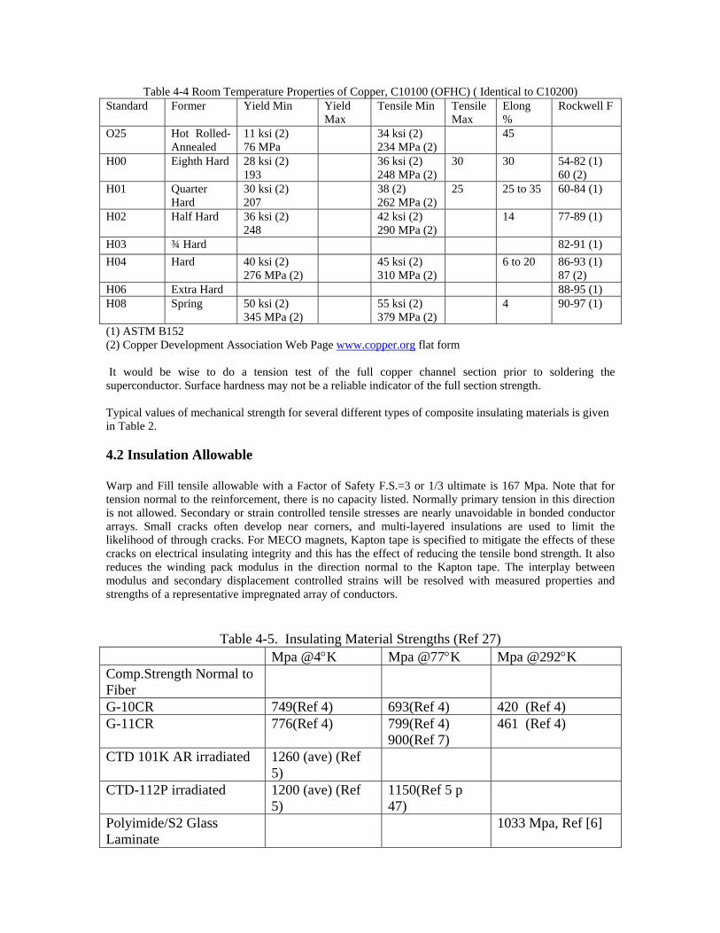
Table 4-4 Room Temperature Properties of Copper, C10100 (OFHC) ( Identical to C10200) Standard Former Yield Min Yield
Max Tensile Min Tensile
Max Elong %
Rockwell F
O25 Hot Rolled-Annealed
11 ksi (2) 76 MPa
34 ksi (2) 234 MPa (2)
45
H00 Eighth Hard 28 ksi (2) 193
36 ksi (2) 248 MPa (2)
30 30 54-82 (1) 60 (2)
H01 Quarter Hard
30 ksi (2) 207
38 (2) 262 MPa (2)
25 25 to 35 60-84 (1)
H02 Half Hard 36 ksi (2) 248
42 ksi (2) 290 MPa (2)
14 77-89 (1)
H03 ¾ Hard 82-91 (1) H04 Hard 40 ksi (2)
276 MPa (2) 45 ksi (2)
310 MPa (2) 6 to 20 86-93 (1)
87 (2) H06 Extra Hard 88-95 (1) H08 Spring 50 ksi (2)
345 MPa (2) 55 ksi (2)
379 MPa (2) 4 90-97 (1)
(1) ASTM B152 (2) Copper Development Association Web Page www.copper.org flat form It would be wise to do a tension test of the full copper channel section prior to soldering the superconductor. Surface hardness may not be a reliable indicator of the full section strength. Typical values of mechanical strength for several different types of composite insulating materials is given in Table 2. 4.2 Insulation Allowable Warp and Fill tensile allowable with a Factor of Safety F.S.=3 or 1/3 ultimate is 167 Mpa. Note that for tension normal to the reinforcement, there is no capacity listed. Normally primary tension in this direction is not allowed. Secondary or strain controlled tensile stresses are nearly unavoidable in bonded conductor arrays. Small cracks often develop near corners, and multi-layered insulations are used to limit the likelihood of through cracks. For MECO magnets, Kapton tape is specified to mitigate the effects of these cracks on electrical insulating integrity and this has the effect of reducing the tensile bond strength. It also reduces the winding pack modulus in the direction normal to the Kapton tape. The interplay between modulus and secondary displacement controlled strains will be resolved with measured properties and strengths of a representative impregnated array of conductors.
Table 4-5. Insulating Material Strengths (Ref 27)
Mpa @4°K Mpa @77°K Mpa @292°K Comp.Strength Normal to Fiber
G-10CR 749(Ref 4) 693(Ref 4) 420 (Ref 4) G-11CR 776(Ref 4) 799(Ref 4)
900(Ref 7) 461 (Ref 4)
CTD 101K AR irradiated 1260 (ave) (Ref 5)
CTD-112P irradiated 1200 (ave) (Ref 5)
1150(Ref 5 p 47)
Polyimide/S2 Glass Laminate
1033 Mpa, Ref [6]
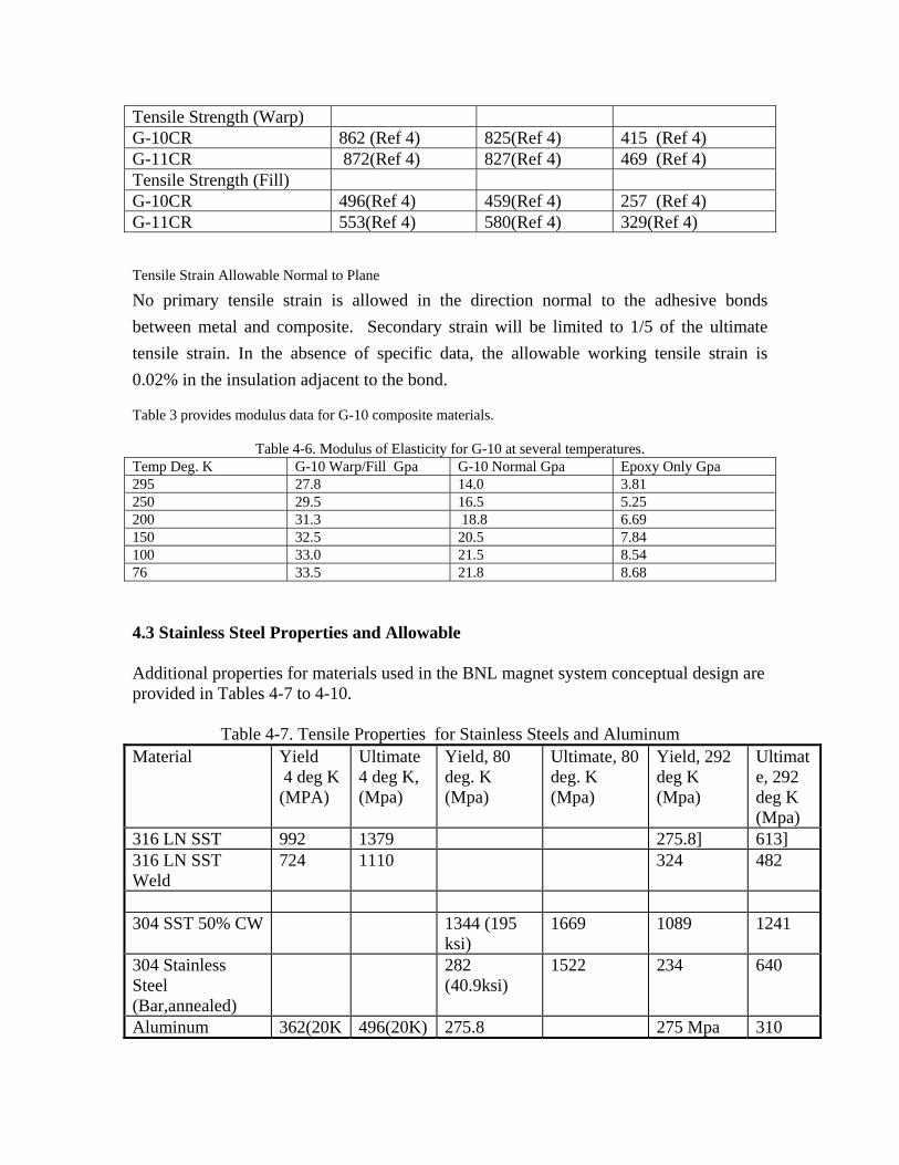
Tensile Strength (Warp) G-10CR 862 (Ref 4) 825(Ref 4) 415 (Ref 4) G-11CR 872(Ref 4) 827(Ref 4) 469 (Ref 4) Tensile Strength (Fill) G-10CR 496(Ref 4) 459(Ref 4) 257 (Ref 4) G-11CR 553(Ref 4) 580(Ref 4) 329(Ref 4) Tensile Strain Allowable Normal to Plane
No primary tensile strain is allowed in the direction normal to the adhesive bonds between metal and composite. Secondary strain will be limited to 1/5 of the ultimate tensile strain. In the absence of specific data, the allowable working tensile strain is 0.02% in the insulation adjacent to the bond. Table 3 provides modulus data for G-10 composite materials.
Table 4-6. Modulus of Elasticity for G-10 at several temperatures. Temp Deg. K G-10 Warp/Fill Gpa G-10 Normal Gpa Epoxy Only Gpa 295 27.8 14.0 3.81 250 29.5 16.5 5.25 200 31.3 18.8 6.69 150 32.5 20.5 7.84 100 33.0 21.5 8.54 76 33.5 21.8 8.68 4.3 Stainless Steel Properties and Allowable Additional properties for materials used in the BNL magnet system conceptual design are provided in Tables 4-7 to 4-10.
Table 4-7. Tensile Properties for Stainless Steels and Aluminum Material Yield
4 deg K (MPA)
Ultimate 4 deg K, (Mpa)
Yield, 80 deg. K (Mpa)
Ultimate, 80 deg. K (Mpa)
Yield, 292 deg K (Mpa)
Ultimate, 292 deg K (Mpa)
316 LN SST 992 1379 275.8] 613] 316 LN SST Weld
724 1110 324 482
304 SST 50% CW 1344 (195
ksi) 1669 1089 1241
304 Stainless Steel (Bar,annealed)
282 (40.9ksi)
1522 234 640
Aluminum 362(20K 496(20K) 275.8 275 Mpa 310
6061T6 ) 40ksi Mpa 45ksi
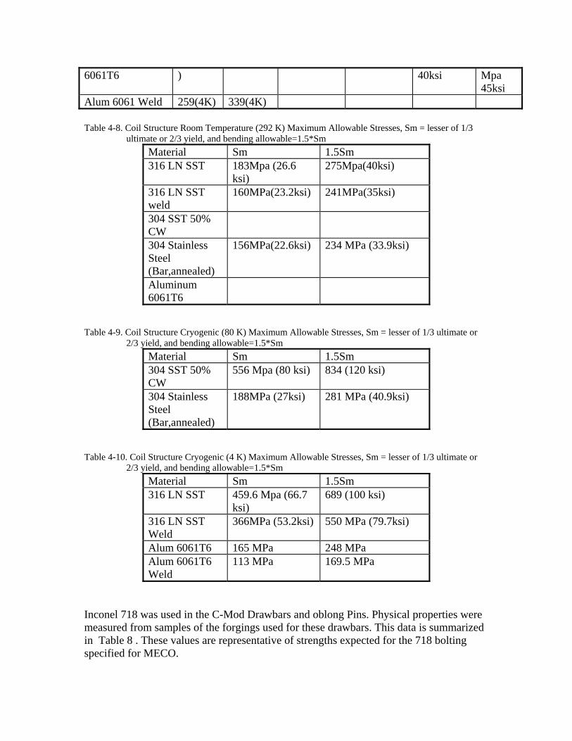
Alum 6061 Weld 259(4K) 339(4K) Table 4-8. Coil Structure Room Temperature (292 K) Maximum Allowable Stresses, Sm = lesser of 1/3
ultimate or 2/3 yield, and bending allowable=1.5*Sm Material Sm 1.5Sm 316 LN SST 183Mpa (26.6
ksi) 275Mpa(40ksi)
316 LN SST weld
160MPa(23.2ksi) 241MPa(35ksi)
304 SST 50% CW
304 Stainless Steel (Bar,annealed)
156MPa(22.6ksi) 234 MPa (33.9ksi)
Aluminum 6061T6
Table 4-9. Coil Structure Cryogenic (80 K) Maximum Allowable Stresses, Sm = lesser of 1/3 ultimate or 2/3 yield, and bending allowable=1.5*Sm
Material Sm 1.5Sm 304 SST 50% CW
556 Mpa (80 ksi) 834 (120 ksi)
304 Stainless Steel (Bar,annealed)
188MPa (27ksi) 281 MPa (40.9ksi)
Table 4-10. Coil Structure Cryogenic (4 K) Maximum Allowable Stresses, Sm = lesser of 1/3 ultimate or 2/3 yield, and bending allowable=1.5*Sm
Material Sm 1.5Sm 316 LN SST 459.6 Mpa (66.7
ksi) 689 (100 ksi)
316 LN SST Weld
366MPa (53.2ksi) 550 MPa (79.7ksi)
Alum 6061T6 165 MPa 248 MPa Alum 6061T6 Weld
113 MPa 169.5 MPa
Inconel 718 was used in the C-Mod Drawbars and oblong Pins. Physical properties were measured from samples of the forgings used for these drawbars. This data is summarized in Table 8 . These values are representative of strengths expected for the 718 bolting specified for MECO.
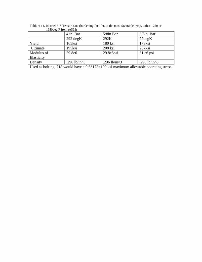
Table 4-11. Inconel 718 Tensile data (hardening for 1 hr. at the most favorable temp, either 1750 or 1950deg F from ref[3])
4 in. Bar 5/8in Bar 5/8in. Bar 292 degK 292K 77degK Yield 165ksi 180 ksi 173ksi Ultimate 195ksi 208 ksi 237ksi Modulus of Elasticity
29.8e6 29.8e6psi 31.e6 psi
Density .296 lb/in^3 .296 lb/in^3 .296 lb/in^3 Used as bolting, 718 would have a 0.6*173=100 ksi maximum allowable operating stress
4.4 Conductor and Insulation systems design and packing fraction
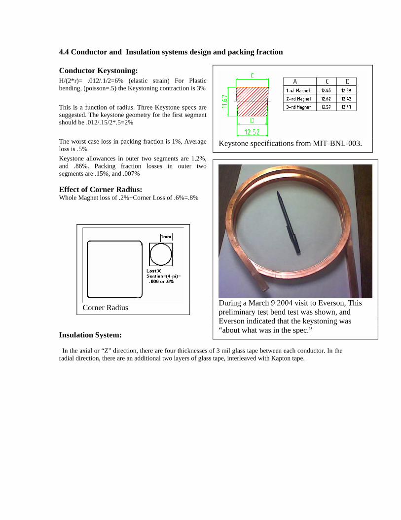
Conductor Keystoning: H/(2*r)= .012/.1/2=6% (elastic strain) For Plastic bending, (poisson=.5) the Keystoning contraction is 3% This is a function of radius. Three Keystone specs are suggested. The keystone geometry for the first segment should be .012/.15/2*.5=2% The worst case loss in packing fraction is 1%, Average loss is .5% Keystone allowances in outer two segments are 1.2%, and .86%. Packing fraction losses in outer two segments are .15%, and .007% Effect of Corner Radius: Whole Magnet loss of .2%+Corner Loss of .6%=.8%
Insulation System:
Keystone specifications from MIT-BNL-003.
During a March 9 2004 visit to Everson, This preliminary test bend test was shown, and Everson indicated that the keystoning was “about what was in the spec.”
Corner Radius
In the axial or “Z” direction, there are four thicknesses of 3 mil glass tape between each conductor. In the radial direction, there are an additional two layers of glass tape, interleaved with Kapton tape.
_ data 1,.15,0,.098,1.0,16,16
_ data 2,.2,0,.002,1.0,1,16 _ data 3,.25,0,.098,1.0,16,16 _ data 4,.3,0,.002,1.0,1,16 _ data 5,.35,0,.098,1.0,16,16 _ read n,r,z,dr,dz,nx,ny _ print "current Densities" _ print 4.5e6/dr/dz _ print 4.5e6/dr/dz/100/100 _ clear let ntpc=624 print "conductor dimensions" let rdim=(dr-(.003*2+.001*2)/39.37)/8-.003*4/39.37 let zdim=dz/(ntpc/8)-.003*4/39.37 print "radial dim";rdim;"m";rdim*39.37;"in" print "Axial dim";zdim;"m";zdim*39.37;"in" print "packing fraction=";ntpc*rdim*zdim/dr/dz print print "conductor dimensions with 2 millimeter channel tolerance" let dr=dr-.002 let rdim=(dr-(.003*2+.001*2)/39.37)/8-.003*4/39.37 let zdim=dz/(ntpc/8)-.003*4/39.37 print "radial dim";rdim;"m";rdim*39.37;"in" print "Axial dim";zdim;"m";zdim*39.37;"in" print "packing fraction=";ntpc*rdim*zdim/(dr+.002)/dz end conductor dimensions radial dim 1.1919799e-2 m .4692825 in Axial dim 1.2515712e-2 m .49274359 in packing fraction= .94991124 conductor dimensions with 2 millimeter channel tolerance radial dim 1.1669799e-2 m .45944 in Axial dim 1.2515712e-2 m .49274359 in packing fraction= .92998827 These packing fractions are based on the coil winding pack and exclude the channel. If the 2 mm channel is included, the packing fraction drops to .911.
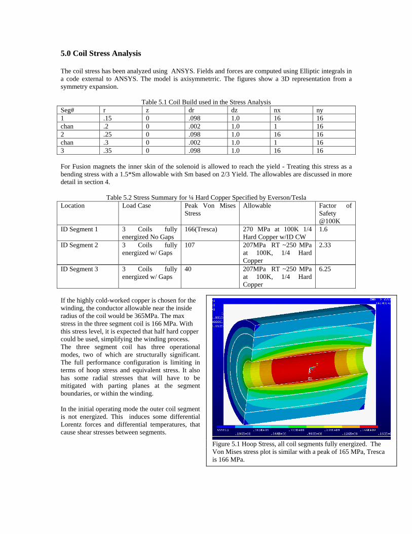
5.0 Coil Stress Analysis The coil stress has been analyzed using ANSYS. Fields and forces are computed using Elliptic integrals in a code external to ANSYS. The model is axisymmetrric. The figures show a 3D representation from a symmetry expansion.
Table 5.1 Coil Build used in the Stress Analysis Seg# r z dr dz nx ny 1 .15 0 .098 1.0 16 16 chan .2 0 .002 1.0 1 16 2 .25 0 .098 1.0 16 16 chan .3 0 .002 1.0 1 16 3 .35 0 .098 1.0 16 16 For Fusion magnets the inner skin of the solenoid is allowed to reach the yield - Treating this stress as a bending stress with a 1.5*Sm allowable with Sm based on 2/3 Yield. The allowables are discussed in more detail in section 4.
Table 5.2 Stress Summary for ¼ Hard Copper Specified by Everson/Tesla
Location Load Case Peak Von Mises Stress
Allowable Factor of Safety @100K
ID Segment 1 3 Coils fully energized No Gaps
166(Tresca) 270 MPa at 100K 1/4 Hard Copper w/ID CW
1.6
ID Segment 2 3 Coils fully energized w/ Gaps
107 207MPa RT ~250 MPa at 100K, 1/4 Hard Copper
2.33
ID Segment 3 3 Coils fully energized w/ Gaps
40 207MPa RT ~250 MPa at 100K, 1/4 Hard Copper
6.25
Figure 5.1 Hoop Stress, all coil segments fully energized. The Von Mises stress plot is similar with a peak of 165 MPa, Tresca is 166 MPa.
If the highly cold-worked copper is chosen for the winding, the conductor allowable near the inside radius of the coil would be 365MPa. The max stress in the three segment coil is 166 MPa. With this stress level, it is expected that half hard copper could be used, simplifying the winding process. The three segment coil has three operational modes, two of which are structurally significant. The full performance configuration is limiting in terms of hoop stress and equivalent stress. It also has some radial stresses that will have to be mitigated with parting planes at the segment boundaries, or within the winding. In the initial operating mode the outer coil segment is not energized. This induces some differential Lorentz forces and differential temperatures, that cause shear stresses between segments.
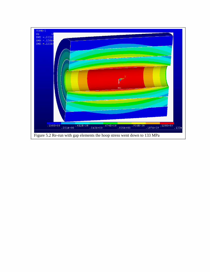
Figure 5.2 Re-run with gap elements the hoop stress went down to 133 MPa
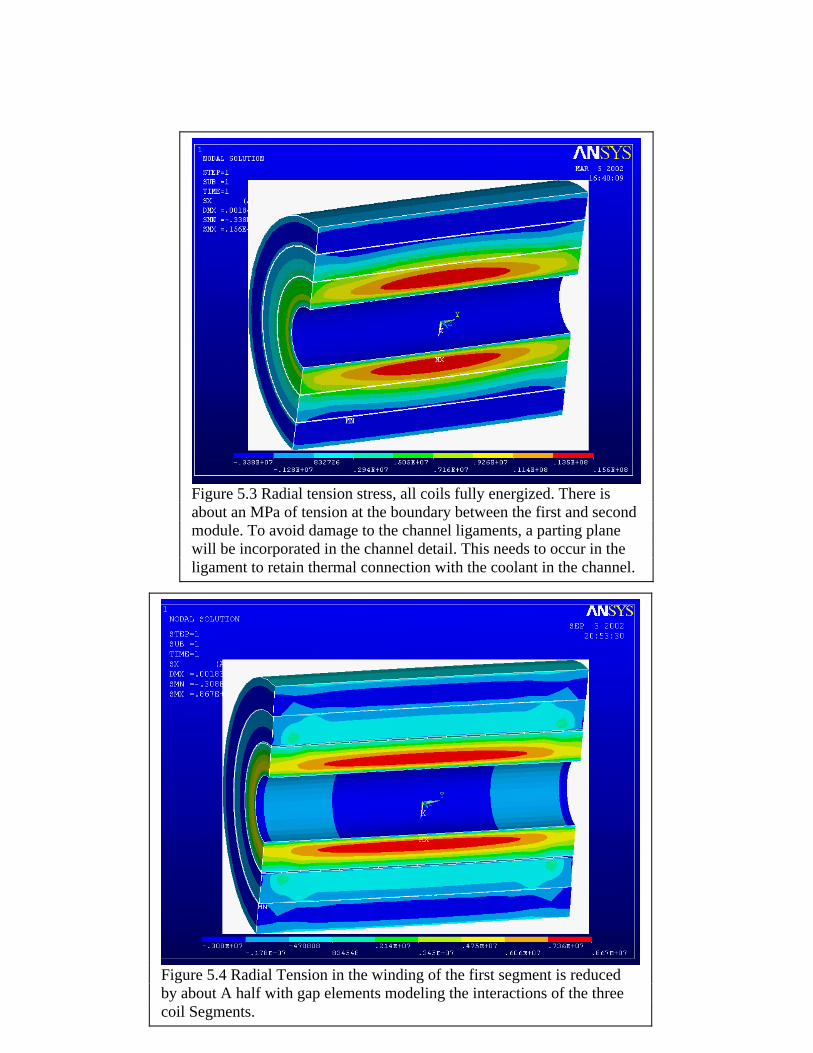
Figure 5.3 Radial tension stress, all coils fully energized. There is about an MPa of tension at the boundary between the first and second module. To avoid damage to the channel ligaments, a parting plane will be incorporated in the channel detail. This needs to occur in the ligament to retain thermal connection with the coolant in the channel.
Figure 5.4 Radial Tension in the winding of the first segment is reduced by about A half with gap elements modeling the interactions of the three coil Segments.
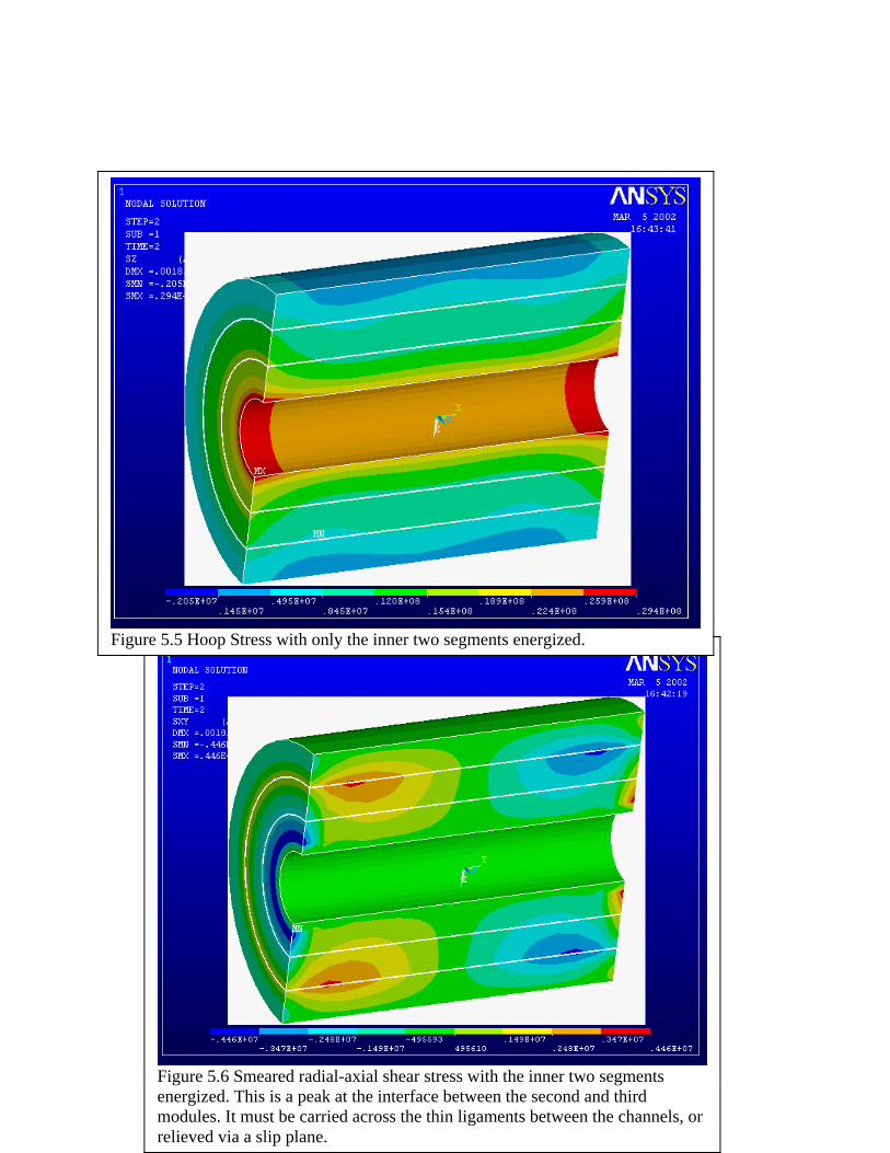
Figure 5.6 Smeared radial-axial shear stress with the inner two segments energized. This is a peak at the interface between the second and third modules. It must be carried across the thin ligaments between the channels, or relieved via a slip plane.
Figure 5.5 Hoop Stress with only the inner two segments energized.
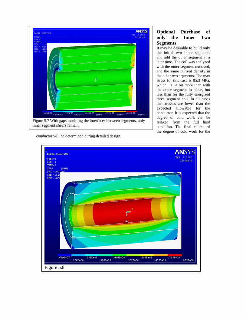
Optional Purchase of only the Inner Two Segments It may be desirable to build only the initial two inner segments and add the outer segment at a later time. The coil was analyzed with the outer segment removed, and the same current density in the other two segments. The max stress for this case is 85.3 MPa, which is a bit more than with the outer segment in place, but less than for the fully energized three segment coil. In all cases the stresses are lower than the expected allowable for the conductor. It is expected that the degree of cold work can be relaxed from the full hard condition. The final choice of the degree of cold work for the
conductor will be determined during detailed design.
Figure 5.7 With gaps modeling the interfaces between segments, only inner segment shears remain.
Figure 5.8
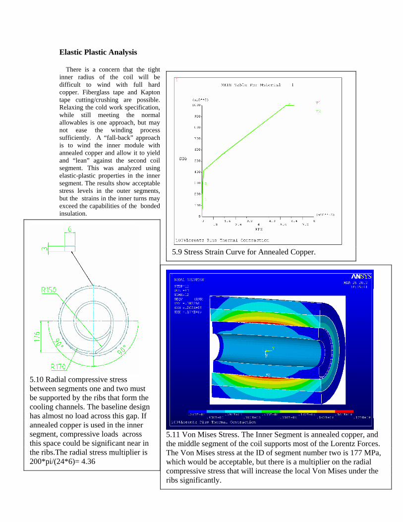
Elastic Plastic Analysis There is a concern that the tight inner radius of the coil will be difficult to wind with full hard copper. Fiberglass tape and Kapton tape cutting/crushing are possible. Relaxing the cold work specification, while still meeting the normal allowables is one approach, but may not ease the winding process sufficiently. A “fall-back” approach is to wind the inner module with annealed copper and allow it to yield and “lean” against the second coil segment. This was analyzed using elastic-plastic properties in the inner segment. The results show acceptable stress levels in the outer segments, but the strains in the inner turns may exceed the capabilities of the bonded insulation.
5.9 Stress Strain Curve for Annealed Copper.
5.10 Radial compressive stress between segments one and two must be supported by the ribs that form the cooling channels. The baseline design has almost no load across this gap. If annealed copper is used in the inner segment, compressive loads across this space could be significant near in the ribs.The radial stress multiplier is 200*pi/(24*6)= 4.36
5.11 Von Mises Stress. The Inner Segment is annealed copper, and the middle segment of the coil supports most of the Lorentz Forces. The Von Mises stress at the ID of segment number two is 177 MPa, which would be acceptable, but there is a multiplier on the radial compressive stress that will increase the local Von Mises under the ribs significantly.
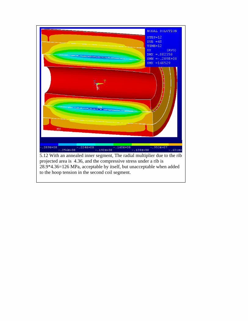
5.12 With an annealed inner segment, The radial multiplier due to the rib projected area is 4.36, and the compressive stress under a rib is 28.9*4.36=126 MPa, acceptable by itself, but unacceptable when added to the hoop tension in the second coil segment.
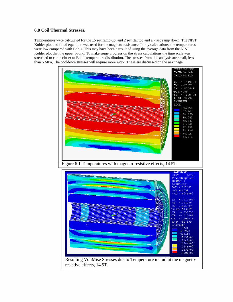
6.0 Coil Thermal Stresses. Temperatures were calculated for the 15 sec ramp-up, and 2 sec flat top and a 7 sec ramp down. The NIST Kohler plot and fitted equation was used for the magneto-resistance. In my calculations, the temperatures were low compared with Bob’s. This may have been a result of using the average data from the NIST Kohler plot that the upper bound. To make some progress on the stress calculations the time scale was stretched to come closer to Bob’s temperature distribution. The stresses from this analysis are small, less than 5 MPa, The cooldown stresses will require more work. These are discussed on the next page.
Figure 6.1 Temperatures with magneto-resistive effects, 14.5T
Resulting VonMise Stresses due to Temperature includint the magneto-resistive effects, 14.5T.
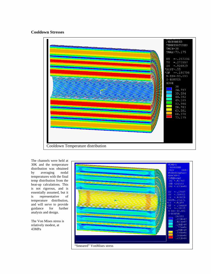
Cooldown Stresses
The channels were held at 30K and the temperature distribution was obtained by averaging nodal temperatures with the final temp distribution from the heat-up calculations. This is not rigorous, and is essentially assumed, but it is representative of temperature distribution, and will serve to provide guidance for further analysis and design. The Von Mises stress is relatively modest, at 43MPa
Cooldown Temperature distribution
“Smeared” VonMises stress
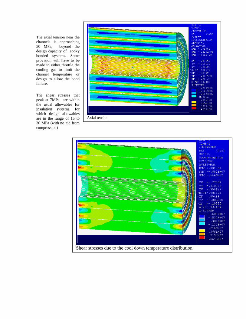
The axial tension near the channels is approaching 50 MPa, beyond the design capacity of epoxy bonded systems. Some provision will have to be made to either throttle the cooling gas to limit the channel temperature or design to allow the bond failure. The shear stresses that peak at 7MPa are within the usual allowables for insulation systems, for which design allowables are in the range of 15 to 30 MPa (with no aid from compression)
Axial tension
Shear stresses due to the cool down temperature distribution
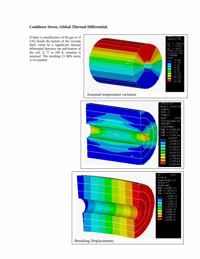
Cooldown Stress, Global Thermal Differential. If there is stratification of He gas or if LN2 floods the bottom of the cryostat there could be a significant thermal differential between top and bottom of the coil. A 77 to 100 K variation is assumed. The resulting 15 MPa stress is Acceptable
Assumed temperature variation
Resulting Displacements
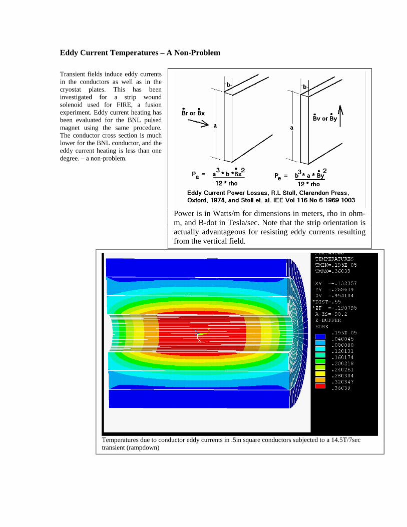
Eddy Current Temperatures – A Non-Problem Transient fields induce eddy currents in the conductors as well as in the cryostat plates. This has been investigated for a strip wound solenoid used for FIRE, a fusion experiment. Eddy current heating has been evaluated for the BNL pulsed magnet using the same procedure. The conductor cross section is much lower for the BNL conductor, and the eddy current heating is less than one degree. – a non-problem.
Power is in Watts/m for dimensions in meters, rho in ohm-m, and B-dot in Tesla/sec. Note that the strip orientation is actually advantageous for resisting eddy currents resulting from the vertical field.
Temperatures due to conductor eddy currents in .5in square conductors subjected to a 14.5T/7sec transient (rampdown)

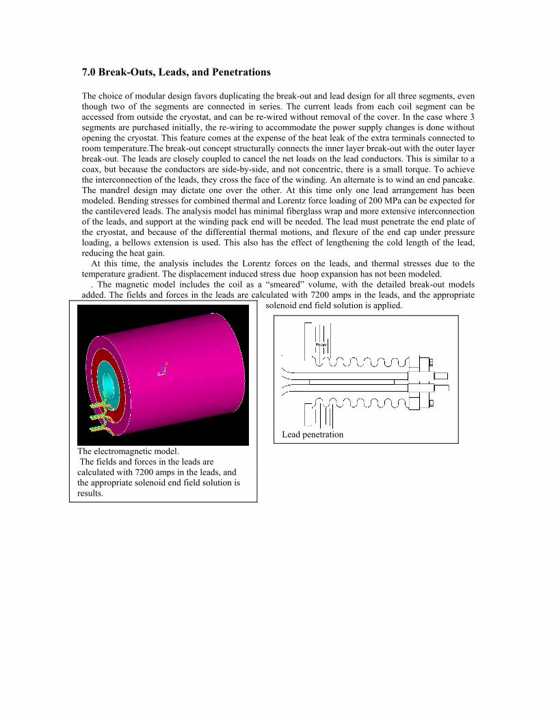
7.0 Break-Outs, Leads, and Penetrations The choice of modular design favors duplicating the break-out and lead design for all three segments, even though two of the segments are connected in series. The current leads from each coil segment can be accessed from outside the cryostat, and can be re-wired without removal of the cover. In the case where 3 segments are purchased initially, the re-wiring to accommodate the power supply changes is done without opening the cryostat. This feature comes at the expense of the heat leak of the extra terminals connected to room temperature.The break-out concept structurally connects the inner layer break-out with the outer layer break-out. The leads are closely coupled to cancel the net loads on the lead conductors. This is similar to a coax, but because the conductors are side-by-side, and not concentric, there is a small torque. To achieve the interconnection of the leads, they cross the face of the winding. An alternate is to wind an end pancake. The mandrel design may dictate one over the other. At this time only one lead arrangement has been modeled. Bending stresses for combined thermal and Lorentz force loading of 200 MPa can be expected for the cantilevered leads. The analysis model has minimal fiberglass wrap and more extensive interconnection of the leads, and support at the winding pack end will be needed. The lead must penetrate the end plate of the cryostat, and because of the differential thermal motions, and flexure of the end cap under pressure loading, a bellows extension is used. This also has the effect of lengthening the cold length of the lead, reducing the heat gain. At this time, the analysis includes the Lorentz forces on the leads, and thermal stresses due to the temperature gradient. The displacement induced stress due hoop expansion has not been modeled. . The magnetic model includes the coil as a “smeared” volume, with the detailed break-out models added. The fields and forces in the leads are calculated with 7200 amps in the leads, and the appropriate
solenoid end field solution is applied.
The electromagnetic model. The fields and forces in the leads are calculated with 7200 amps in the leads, and the appropriate solenoid end field solution is results.
Lead penetration
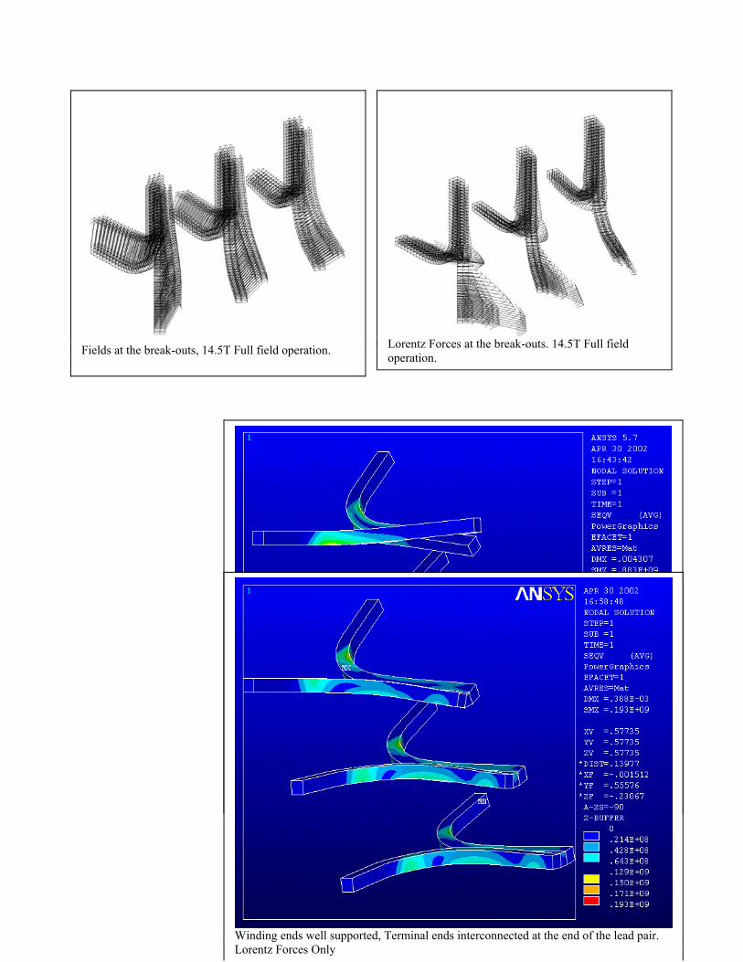
Fields at the break-outs, 14.5T Full field operation.
Lorentz Forces at the break-outs. 14.5T Full field operation.
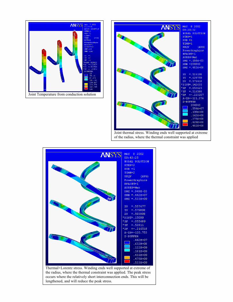
Winding ends well supported, Terminal ends Un-supported and not interconnected Lorentz Forces Only
Winding ends well supported, Terminal ends interconnected at the end of the lead pair. Lorentz Forces Only
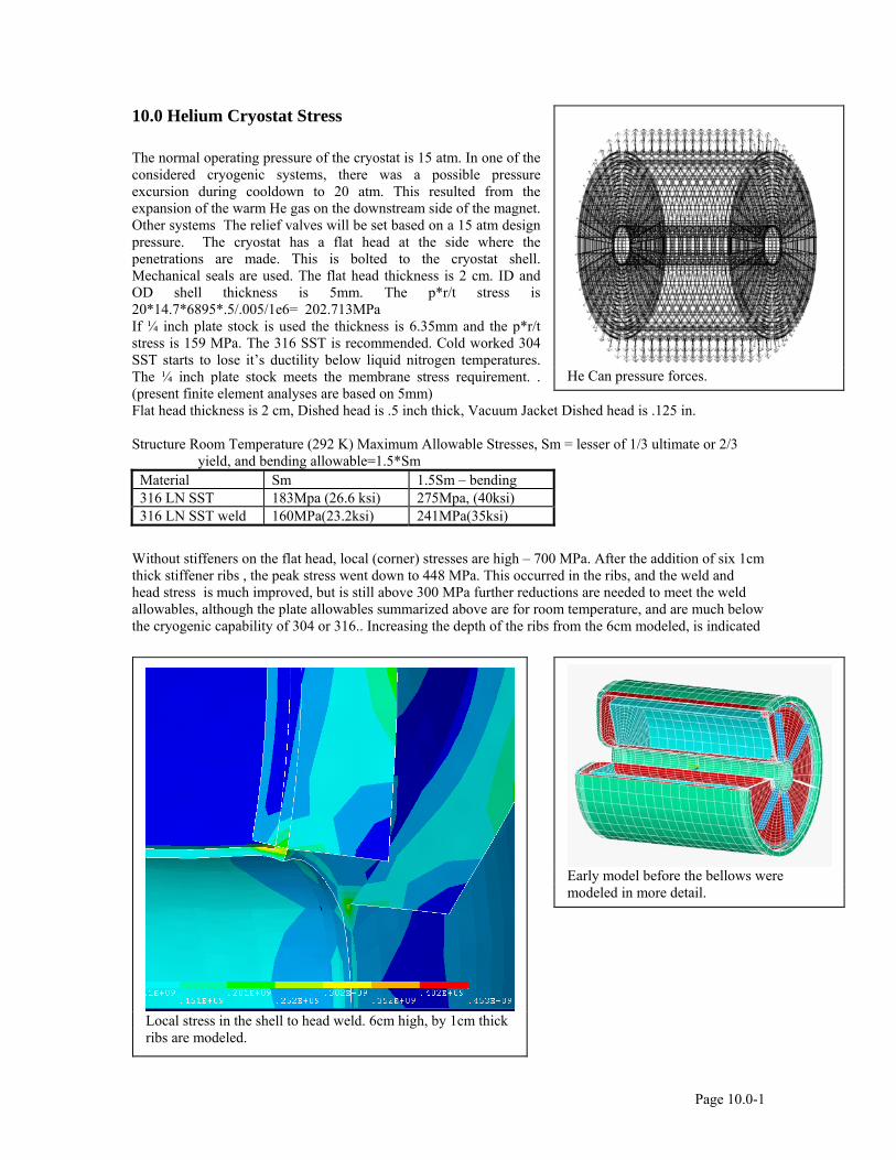
Joint Temperature from conduction solution
Joint thermal stress. Winding ends well supported at extreme of the radius, where the thermal constraint was applied
Thermal+Lorentz stress. Winding ends well supported at extreme of the radius, where the thermal constraint was applied. The peak stress occurs where the relatively short interconnection ends. This will be lengthened, and will reduce the peak stress.

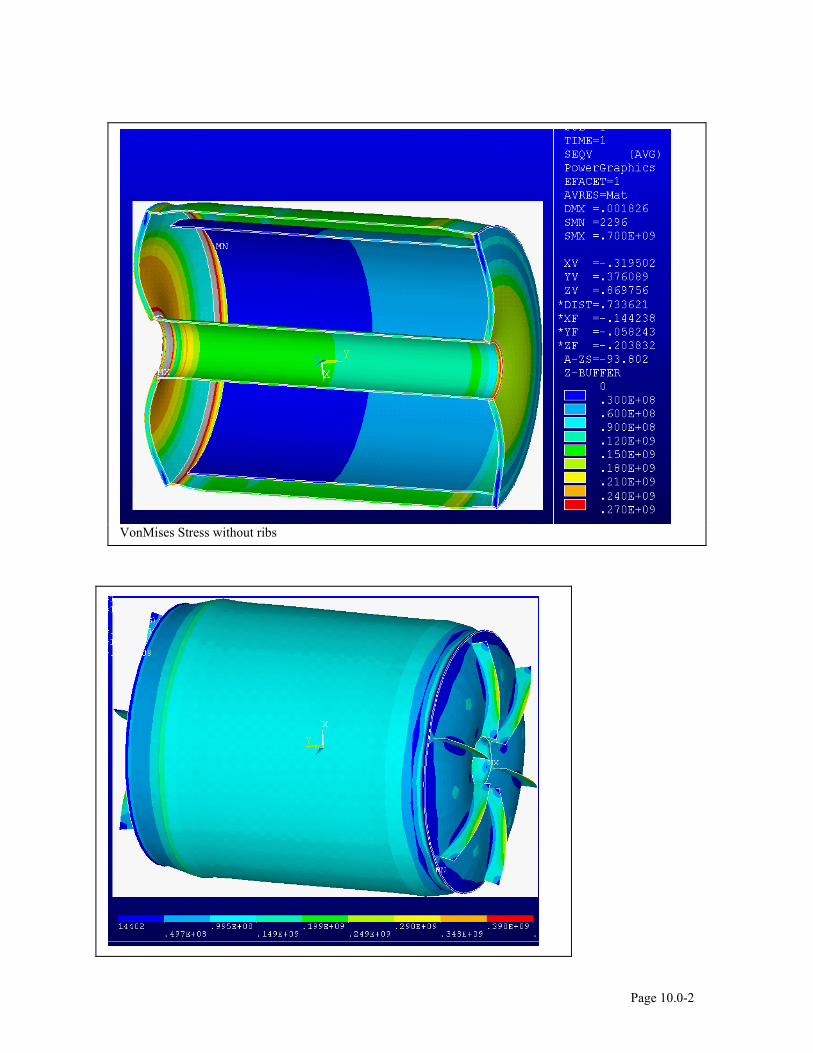
10.0 Helium Cryostat Stress The normal operating pressure of the cryostat is 15 atm. In one of the considered cryogenic systems, there was a possible pressure excursion during cooldown to 20 atm. This resulted from the expansion of the warm He gas on the downstream side of the magnet. Other systems The relief valves will be set based on a 15 atm design pressure. The cryostat has a flat head at the side where the penetrations are made. This is bolted to the cryostat shell. Mechanical seals are used. The flat head thickness is 2 cm. ID and OD shell thickness is 5mm. The p*r/t stress is 20*14.7*6895*.5/.005/1e6= 202.713MPa If ¼ inch plate stock is used the thickness is 6.35mm and the p*r/t stress is 159 MPa. The 316 SST is recommended. Cold worked 304 SST starts to lose it’s ductility below liquid nitrogen temperatures. The ¼ inch plate stock meets the membrane stress requirement. . (present finite element analyses are based on 5mm) Flat head thickness is 2 cm, Dished head is .5 inch thick, Vacuum Jacket Dished head is .125 in.
Structure Room Temperature (292 K) Maximum Allowable Stresses, Sm = lesser of 1/3 ultimate or 2/3
yield, and bending allowable=1.5*Sm Material Sm 1.5Sm – bending 316 LN SST 183Mpa (26.6 ksi) 275Mpa, (40ksi) 316 LN SST weld 160MPa(23.2ksi) 241MPa(35ksi)
Without stiffeners on the flat head, local (corner) stresses are high – 700 MPa. After the addition of six 1cm thick stiffener ribs , the peak stress went down to 448 MPa. This occurred in the ribs, and the weld and head stress is much improved, but is still above 300 MPa further reductions are needed to meet the weld allowables, although the plate allowables summarized above are for room temperature, and are much below the cryogenic capability of 304 or 316.. Increasing the depth of the ribs from the 6cm modeled, is indicated
He Can pressure forces.
Local stress in the shell to head weld. 6cm high, by 1cm thick ribs are modeled.
Early model before the bellows were modeled in more detail.
Page 10.0-1
VonMises Stress without ribs
Page 10.0-2
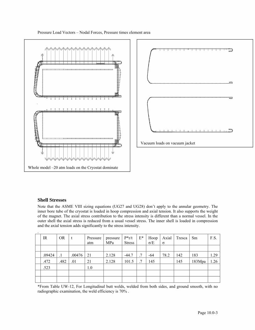
Pressure Load Vectors – Nodal Forces, Pressure times element area
Whole model –20 atm loads on the Cryostat dominate
Vacuum loads on vacuum jacket
Shell Stresses Note that the ASME VIII sizing equations (UG27 and UG28) don’t apply to the annular geometry. The inner bore tube of the cryostat is loaded in hoop compression and axial tension. It also supports the weight of the magnet. The axial stress contribution to the stress intensity is different than a normal vessel. In the outer shell the axial stress is reduced from a usual vessel stress. The inner shell is loaded in compression and the axial tension adds significantly to the stress intensity. . IR OR t Pressure
atm pressure MPa
P*r/t Stress
E* Hoop σ/E
Axial σ
Tresca Sm F.S.
.09424 .1 .00476 21 2.128 -44.7 .7 -64 78.2 142 183 1.29 .472 .482 .01 21 2.128 101.5 .7 145 145 183Mpa 1.26 .523 1.0 *From Table UW-12, For Longitudinal butt welds, welded from both sides, and ground smooth, with no radiographic examination, the weld efficiency is 70% .
Page 10.0-3
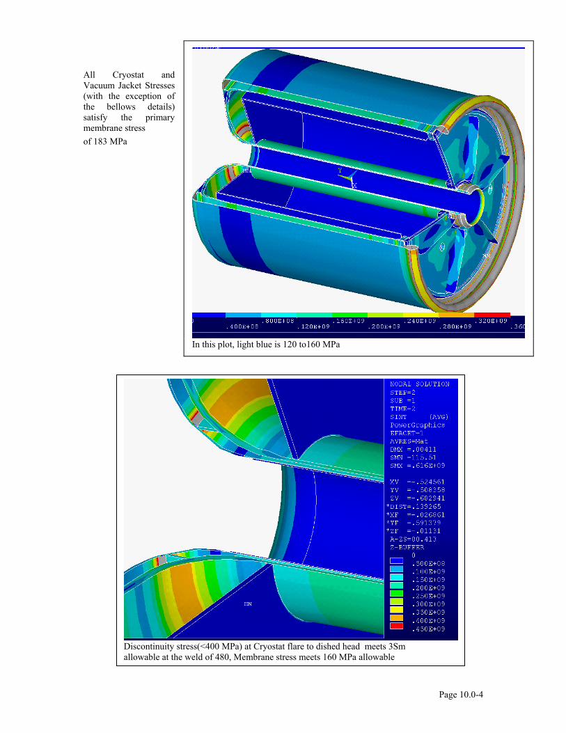
All Cryostat and Vacuum Jacket Stresses (with the exception of the bellows details) satisfy the primary membrane stress of 183 MPa
In this plot, light blue is 120 to160 MPa
Discontinuity stress(<400 MPa) at Cryostat flare to dished head meets 3Sm allowable at the weld of 480, Membrane stress meets 160 MPa allowable
Page 10.0-4
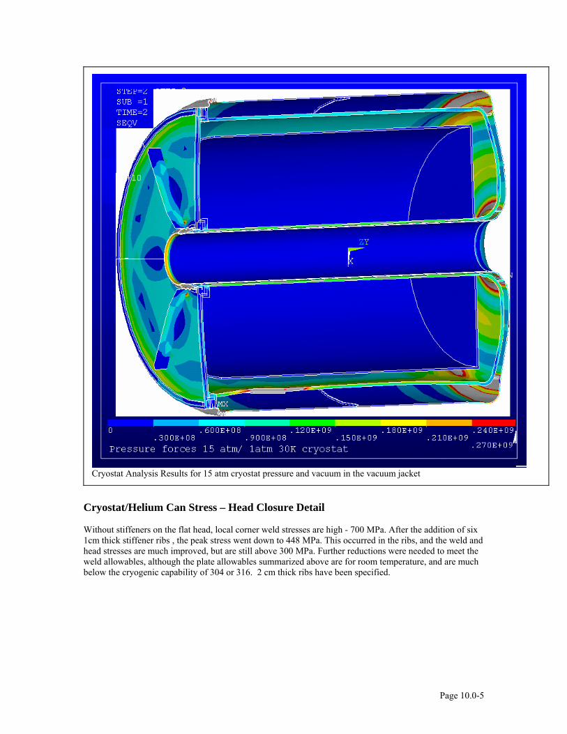
Cryostat Analysis Results for 15 atm cryostat pressure and vacuum in the vacuum jacket
Cryostat/Helium Can Stress – Head Closure Detail
Without stiffeners on the flat head, local corner weld stresses are high - 700 MPa. After the addition of six 1cm thick stiffener ribs , the peak stress went down to 448 MPa. This occurred in the ribs, and the weld and head stresses are much improved, but are still above 300 MPa. Further reductions were needed to meet the weld allowables, although the plate allowables summarized above are for room temperature, and are much below the cryogenic capability of 304 or 316. 2 cm thick ribs have been specified.
Page 10.0-5
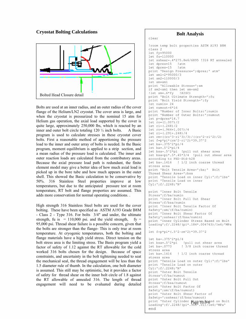
Cryostat Bolting Calculations
Bolts are used at an inner radius, and an outer radius of the cover flange of the Helium/LN2 cryostat. The cover area is large, and when the cryostat is pressurized to the nominal 15 atm for Helium gas operation, the axial load supported by the cover is quite large, approximately 250,000 lbs, which is reacted by an inner and outer bolt circle totaling 120 ½ inch bolts. A Basic program is used to calculate stresses in these cryostat cover bolts. First a reasonable method of apportioning the pressure load to the inner and outer array of bolts is needed. In the Basic program, moment equilibrium is applied to a strip section, and a mean radius of the pressure load is calculated. The inner and outer reaction loads are calculated from the contributory areas. Because the axial pressure load path is redundant, the finite element model may give a better idea of how much axial load is picked up in the bore tube and how much appears in the outer shell. This showed the Basic calculation to be conservative by 50%. 316 Stainless Steel properties improve at low temperatures, but due to the anticipated pressure test at room temperature, RT bolt and flange properties are assumed. This adds more conservatism for normal operating conditions. .
High strength 316 Stainless Steel bolts are used for the cover bolting. These have been specified as ASTM A193 Grade B8M - Class 2 - Type 316. For bolts 3/4" and under, the ultimate strength, fu is = 110,000 psi. and the yield strength, fy = 95,000 psi. Thread shear failure is a possible concern, given that the bolts are stronger than the flange- This is only true at room temperature. At cryogenic temperatures, both the bolting and flange materials have a high yield stress. Direct tension on the bolt stress area is the limiting stress. The Basis program yield a factor of safety of 1.12 against the RT allowable for the cold worked 316 bolts chosen for the design. Because of space constraints, and uncertainty in the bolt tightening needed to seat the mechanical seal, the thread engagement will be less than the 1.5 diameter rule of thumb. In the calculation, one bolt diameter is assumed. This still may be optimistic, but it provides a factor of safety for thread shear on the inner bolt circle of 1.8 against the RT allowable of annealed 316. The length of thread engagement will need to be evaluated during detailed
Page 10.0-6
Bolt Analysis clear !room temp bolt properties ASTM A193 B8M class 2 let fy=95000 let fu=110000 let sshear=.4*275.8e6/6895 !316 RT annealed let dpres=15 !atm let dpres=15 !atm print "Design Pressure=";dpres;" atm" let sm1=2*95000/3 let sm2=110000/3 let sm=sm1 print "Allowable Stress=";sm if sm2<sm1 then let sm=sm2 !let sm=.6*fy !AISC) print "Bolt Ultimate Strength=";fu print "Bolt Yield Strength=";fy let numin= 24 let numout=6*16 print "Number of Inner Bolts:";numin print "Number of Outer Bolts:";numout let p=dpres*14.7 let ro=(1.007)/2 let ri=(.248)/2 let ro=(.964+1.007)/4 let ri=(.291+.248)/4 let rm=((ro^3-ri^3)/3)/((ro^2-ri^2)/2) let f=p*pi*(rm^2-ri^2)*39.37^2 let ba=.375^2*pi/4 let ba=.5^2*pi/4 let bsa=.5^2*pi !pull out shear area let bsa=pi*.5*.45*3/4 !pull out shear area according to FED-Std-h28 let ba=.1416 ! 1/2 inch coarse thread stress area print "Bolt Tensile Area=";ba;" Bolt Thread Shear Area=";bsa print "Tensile Load on inner Cyl:";f;"lbs" print "Tensile Load on inner Cyl:";f/.2248;"N" print "Inner Bolt Tensile Stress";f/ba/numin print "Inner Bolt Pull Out Shear Stress";f/bsa/numin print "Inner Bolt Tensile Factor Of Safety";sm/(f/ba/numin) print "Inner Bolt Shear Factor Of Safety";sshear/(f/bsa/numin) print "Inner Cylinder Stress Based on Bolt Loading";f/.2248/(pi*.184*.004763)/1e6;"MPa" let f=p*pi*(.5^2-rm^2)*39.37^2 let ba=.375^2*pi/4 let bsa=.5^2*pi !pull out shear area let ba=.0773 ! 3/8 inch coarse thread stress area let ba=.1416 ! 1/2 inch coarse thread stress area print "Tensile Load on outer Cyl:";f;"lbs" print "Tensile Load on outer Cyl:";f/.2248;"N" print "Outer Bolt Tensile Stress";f/ba/numout print "Outer Bolt Pull Out Stress";f/bsa/numout print "Outer Bolt Factor Of Safety";sm/(f/ba/numout) print "Outer Bolt Shear Factor of Safety=";sshear/(f/bsa/numout) print "Outer Cylinder Stress Based on Bolt Loading";f/.2248/(pi*.966*.01)/1e6;"MPa" end
Bolted Head Closure detail
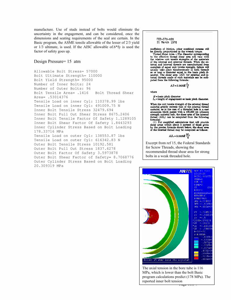
manufacture. Use of studs instead of bolts would eliminate the uncertainty in the engagement, and can be considered, once the dimensions and seating requirements of the seal are certain. In the Basic program, the ASME tensile allowable of the lesser of 2/3 yield or 1/3 ultimate, is used. If the AISC allowable of.6*fy is used the factor of safety goes up.
Design Pressure= 15 atm
Allowable Bolt Stress= 57000 Bolt Ultimate Strength= 110000 Bolt Yield Strength= 95000 Number of Inner Bolts: 24 Number of Outer Bolts: 96 Bolt Tensile Area= .1416 Bolt Thread Shear Area= .53014376 Tensile Load on inner Cyl: 110378.99 lbs Tensile Load on inner Cyl: 491009.75 N Inner Bolt Tensile Stress 32479.694 Inner Bolt Pull Out Shear Stress 8675.2406 Inner Bolt Tensile Factor Of Safety 1.1289105 Inner Bolt Shear Factor Of Safety 1.8443293 Inner Cylinder Stress Based on Bolt Loading 178.33716 MPa Tensile Load on outer Cyl: 138553.87 lbs Tensile Load on outer Cyl: 616342.83 N Outer Bolt Tensile Stress 10192.581 Outer Bolt Pull Out Stress 1837.6278 Outer Bolt Factor Of Safety 3.5973878 Outer Bolt Shear Factor of Safety= 8.7068776 Outer Cylinder Stress Based on Bolt Loading 20.309319 MPa
Excerpt from ref 15, the Federal Standards for Screw Threads, showing the recommended thread shear area for strong bolts in a weak threaded hole.
The axial tension in the bore tube is 116 MPa, which is lower than the bolt Basic program calculations predict (178 MPa). The reported inner bolt tension
Page 10.0-7
Pressure= 20 atm Allowable Bolt Stress= 57000 Bolt Ultimate Strength= 110000 Bolt Yield Strength= 95000 Number of Inner Bolts: 24 Number of Outer Bolts: 96 Bolt Tensile Area= .1416 Bolt Thread Shear Area= .53014376 Tensile Load on inner Cyl: 147171.99 lbs Tensile Load on inner Cyl: 654679.67 N Inner Bolt Tensile Stress 43306.259 Inner Bolt Pull Out Shear Stress 11566.987 Inner Bolt Tensile Factor Of Safety .84668286 Inner Bolt Shear Factor Of Safety 1.3832469 Inner Cylinder Stress Based on Bolt Loading 237.78288 MPa Tensile Load on outer Cyl: 184738.49 lbs Tensile Load on outer Cyl: 821790.44 N Outer Bolt Tensile Stress 13590.108 Outer Bolt Pull Out Stress 2450.1703 Outer Bolt Factor Of Safety 2.6980409 Outer Bolt Shear Factor of Safety= 6.5301582 Outer Cylinder Stress Based on Bolt Loading 27.079091 MPa Ok. echo off
Page 10.0-8
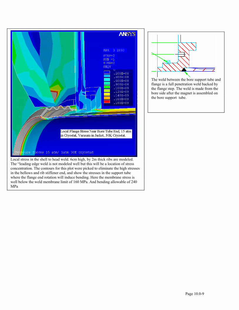
Local stress in the shell to head weld. 6cm high, by 2m thick ribs are modeled. The “leading edge weld is not modeled well but this will be a location of stress concentration. The contours for this plot were picked to eliminate the high stresses in the bellows and rib stiffener end, and show the stresses in the support tube where the flange end rotation will induce bending. Here the membrane stress is well below the weld membrane limit of 160 MPa. And bending allowable of 240 MPa
The weld between the bore support tube and flange is a full penetration weld backed by the flange step. The weld is made from the bore side after the magnet is assembled on the bore support tube.
Page 10.0-9
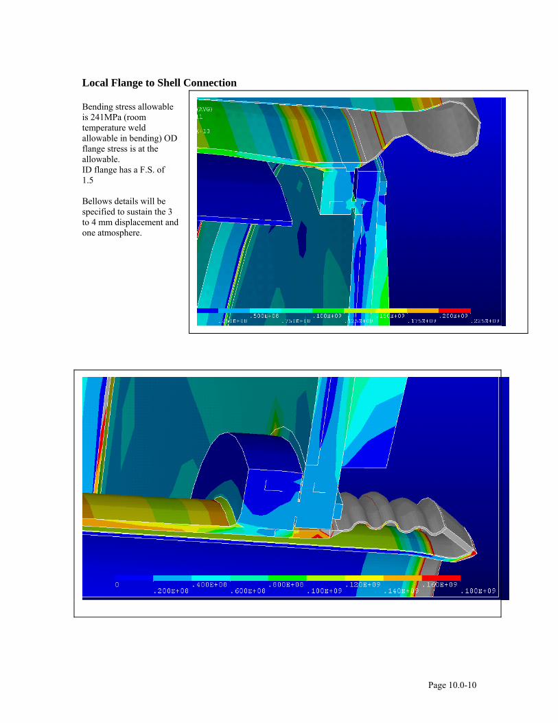
Local Flange to Shell Connection
Bending stress allowable is 241MPa (room temperature weld allowable in bending) OD flange stress is at the allowable. ID flange has a F.S. of 1.5 Bellows details will be specified to sustain the 3 to 4 mm displacement and one atmosphere.
Page 10.0-10
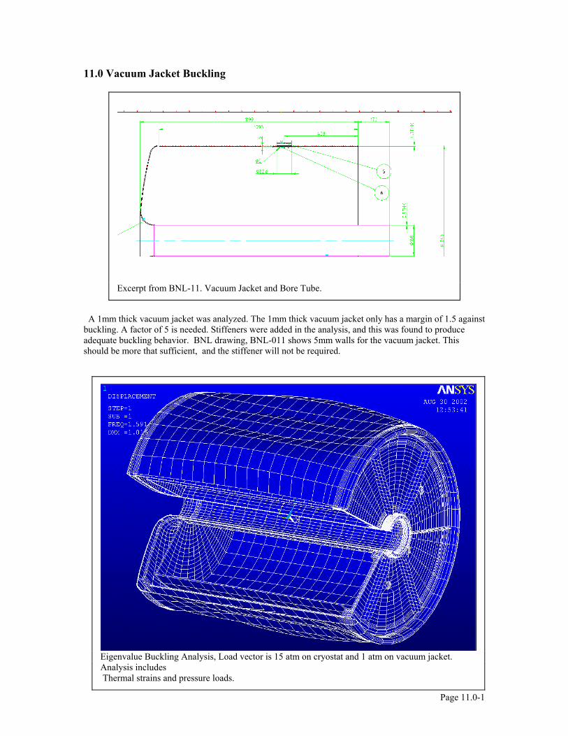
11.0 Vacuum Jacket Buckling
Page 11.0-1
A 1mm thick vacuum jacket was analyzed. The 1mm thick vacuum jacket only has a margin of 1.5 against buckling. A factor of 5 is needed. Stiffeners were added in the analysis, and this was found to produce adequate buckling behavior. BNL drawing, BNL-011 shows 5mm walls for the vacuum jacket. This should be more that sufficient, and the stiffener will not be required.
Excerpt from BNL-11. Vacuum Jacket and Bore Tube.
Eigenvalue Buckling Analysis, Load vector is 15 atm on cryostat and 1 atm on vacuum jacket. Analysis includes Thermal strains and pressure loads.
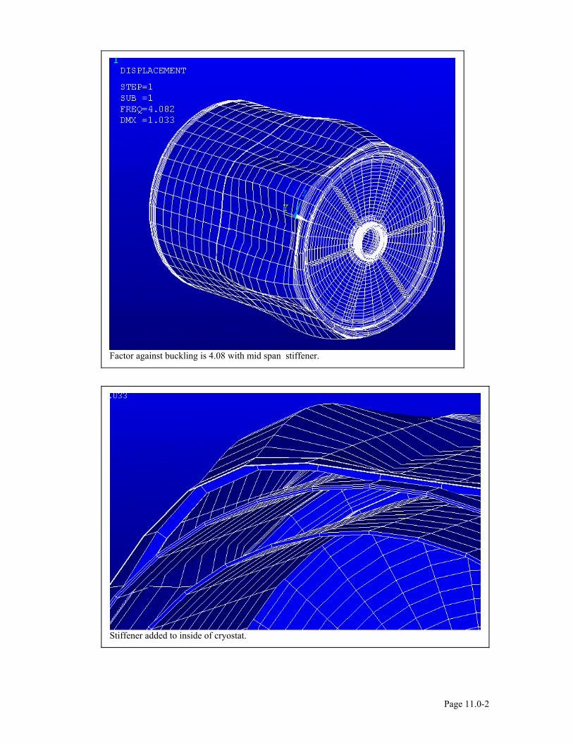
Factor against buckling is 4.08 with mid span stiffener.
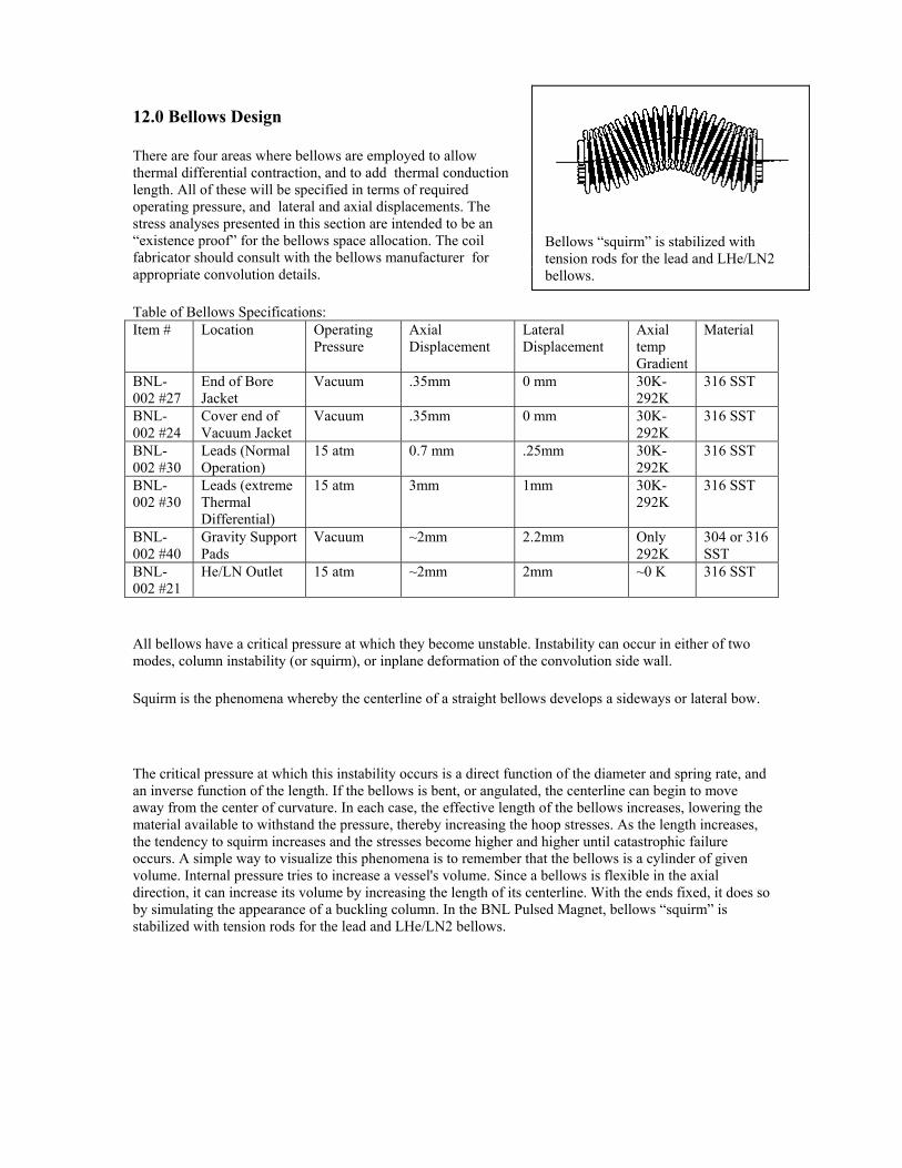
Stiffener added to inside of cryostat.
Page 11.0-2
Bellows “squirm” is stabilized with tension rods for the lead and LHe/LN2 bellows.
12.0 Bellows Design
There are four areas where bellows are employed to allow thermal differential contraction, and to add thermal conduction length. All of these will be specified in terms of required operating pressure, and lateral and axial displacements. The stress analyses presented in this section are intended to be an “existence proof” for the bellows space allocation. The coil fabricator should consult with the bellows manufacturer for appropriate convolution details.
Table of Bellows Specifications: Item # Location Operating
Pressure Axial Displacement
Lateral Displacement
Axial temp Gradient
Material
BNL-002 #27
End of Bore Jacket
Vacuum .35mm 0 mm 30K-292K
316 SST
BNL-002 #24
Cover end of Vacuum Jacket
Vacuum .35mm 0 mm 30K-292K
316 SST
BNL-002 #30
Leads (Normal Operation)
15 atm 0.7 mm .25mm 30K-292K
316 SST
BNL-002 #30
Leads (extreme Thermal Differential)
15 atm 3mm 1mm 30K-292K
316 SST
BNL-002 #40
Gravity Support Pads
Vacuum ~2mm 2.2mm Only 292K
304 or 316 SST
BNL-002 #21
He/LN Outlet 15 atm ~2mm 2mm ~0 K 316 SST
All bellows have a critical pressure at which they become unstable. Instability can occur in either of two modes, column instability (or squirm), or inplane deformation of the convolution side wall.
Squirm is the phenomena whereby the centerline of a straight bellows develops a sideways or lateral bow.
The critical pressure at which this instability occurs is a direct function of the diameter and spring rate, and an inverse function of the length. If the bellows is bent, or angulated, the centerline can begin to move away from the center of curvature. In each case, the effective length of the bellows increases, lowering the material available to withstand the pressure, thereby increasing the hoop stresses. As the length increases, the tendency to squirm increases and the stresses become higher and higher until catastrophic failure occurs. A simple way to visualize this phenomena is to remember that the bellows is a cylinder of given volume. Internal pressure tries to increase a vessel's volume. Since a bellows is flexible in the axial direction, it can increase its volume by increasing the length of its centerline. With the ends fixed, it does so by simulating the appearance of a buckling column. In the BNL Pulsed Magnet, bellows “squirm” is stabilized with tension rods for the lead and LHe/LN2 bellows.
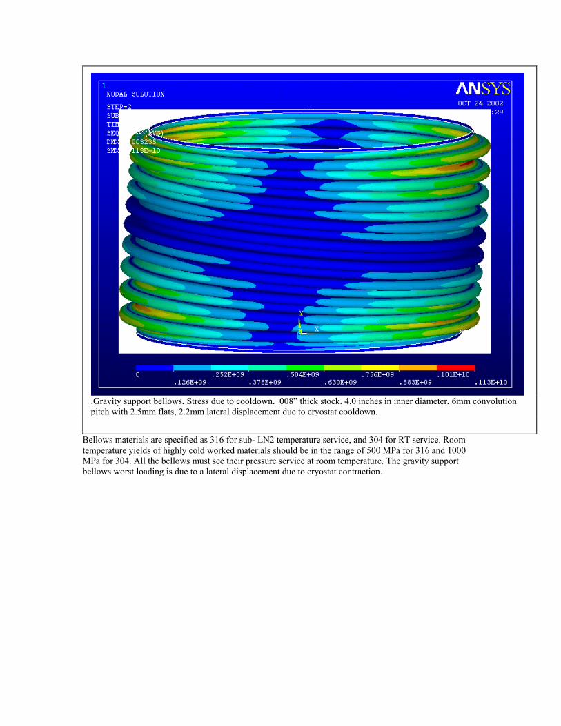
.Gravity support bellows, Stress due to cooldown. 008” thick stock. 4.0 inches in inner diameter, 6mm convolution pitch with 2.5mm flats, 2.2mm lateral displacement due to cryostat cooldown.
Bellows materials are specified as 316 for sub- LN2 temperature service, and 304 for RT service. Room temperature yields of highly cold worked materials should be in the range of 500 MPa for 316 and 1000 MPa for 304. All the bellows must see their pressure service at room temperature. The gravity support bellows worst loading is due to a lateral displacement due to cryostat contraction.
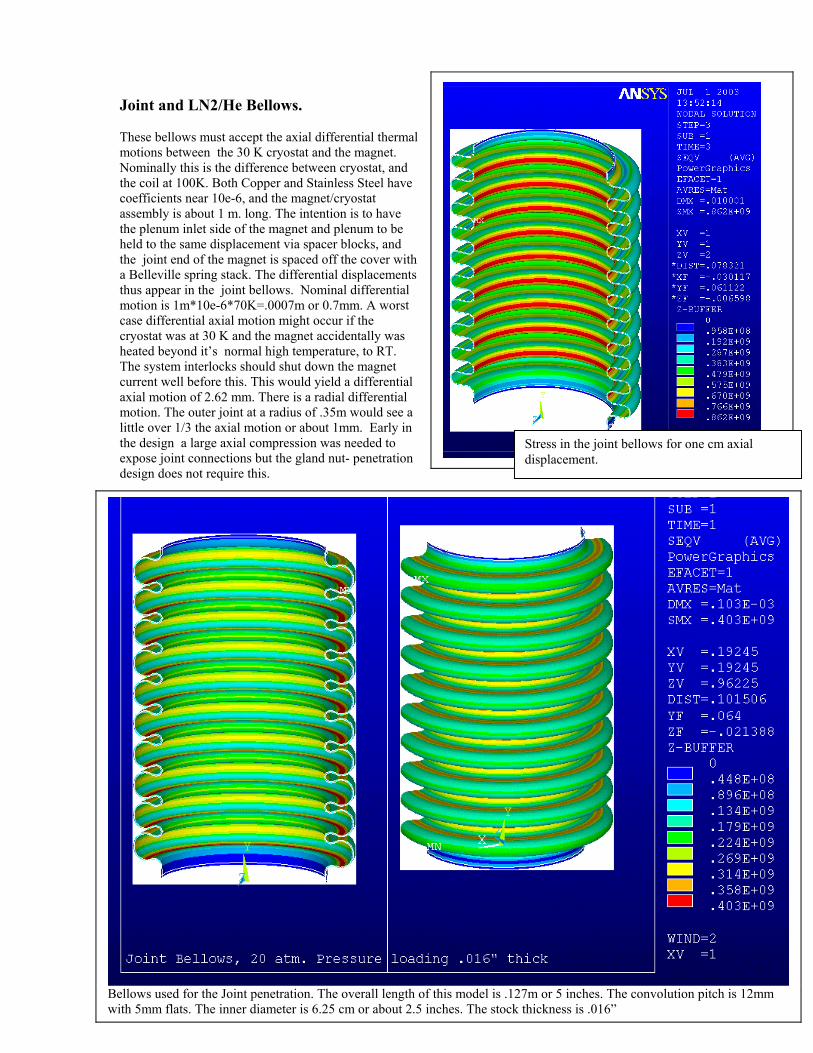
Joint and LN2/He Bellows. These bellows must accept the axial differential thermal motions between the 30 K cryostat and the magnet. Nominally this is the difference between cryostat, and the coil at 100K. Both Copper and Stainless Steel have coefficients near 10e-6, and the magnet/cryostat assembly is about 1 m. long. The intention is to have the plenum inlet side of the magnet and plenum to be held to the same displacement via spacer blocks, and the joint end of the magnet is spaced off the cover with a Belleville spring stack. The differential displacements thus appear in the joint bellows. Nominal differential motion is 1m*10e-6*70K=.0007m or 0.7mm. A worst case differential axial motion might occur if the cryostat was at 30 K and the magnet accidentally was heated beyond it’s normal high temperature, to RT. The system interlocks should shut down the magnet current well before this. This would yield a differential axial motion of 2.62 mm. There is a radial differential motion. The outer joint at a radius of .35m would see a little over 1/3 the axial motion or about 1mm. Early in the design a large axial compression was needed to expose joint connections but the gland nut- penetration design does not require this.
Bellows used for the Joint penetration. The overall length of this model is .127m or 5 inches. The convolution pitch is 12mm with 5mm flats. The inner diameter is 6.25 cm or about 2.5 inches. The stock thickness is .016”
Stress in the joint bellows for one cm axial displacement.
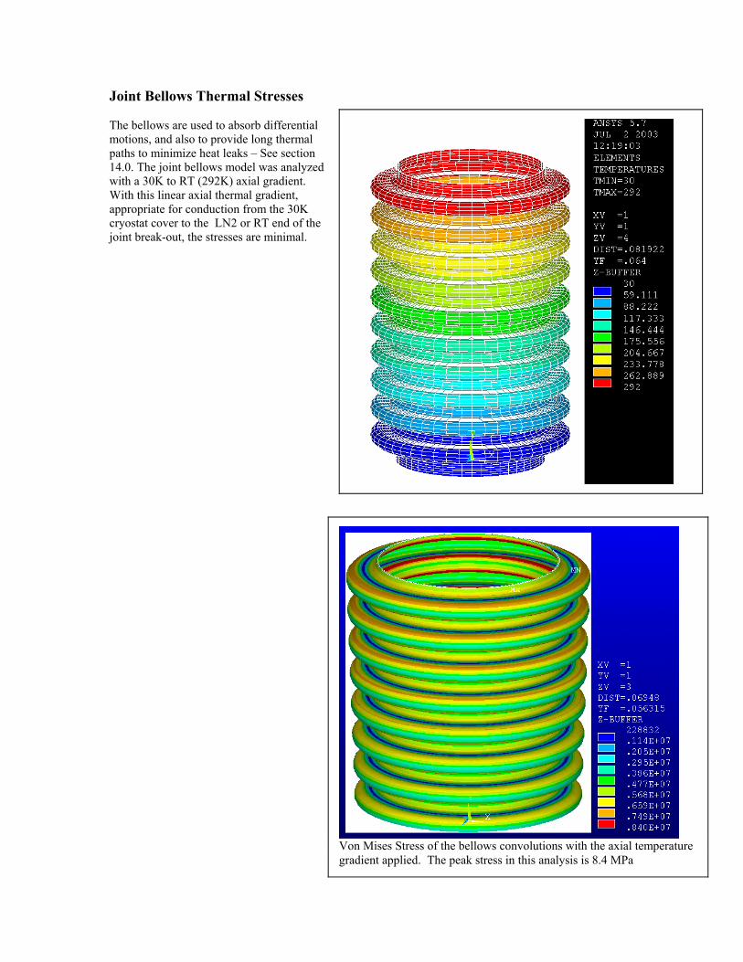
Joint Bellows Thermal Stresses
Von Mises Stress of the bellows convolutions with the axial temperature gradient applied. The peak stress in this analysis is 8.4 MPa
The bellows are used to absorb differential motions, and also to provide long thermal paths to minimize heat leaks – See section 14.0. The joint bellows model was analyzed with a 30K to RT (292K) axial gradient. With this linear axial thermal gradient, appropriate for conduction from the 30K cryostat cover to the LN2 or RT end of the joint break-out, the stresses are minimal.
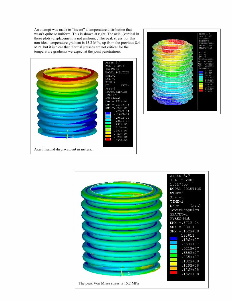
An attempt was made to “invent” a temperature distribution that wasn’t quite so uniform. This is shown at right. The axial (vertical in these plots) displacement is not uniform. . The peak stress for this non-ideal temperature gradient is 15.2 MPa, up from the previous 8.4 MPa, but it is clear that thermal stresses are not critical for the temperature gradients we expect at the joint penetrations.
Axial thermal displacement in meters.
The peak Von Mises stress is 15.2 MPa
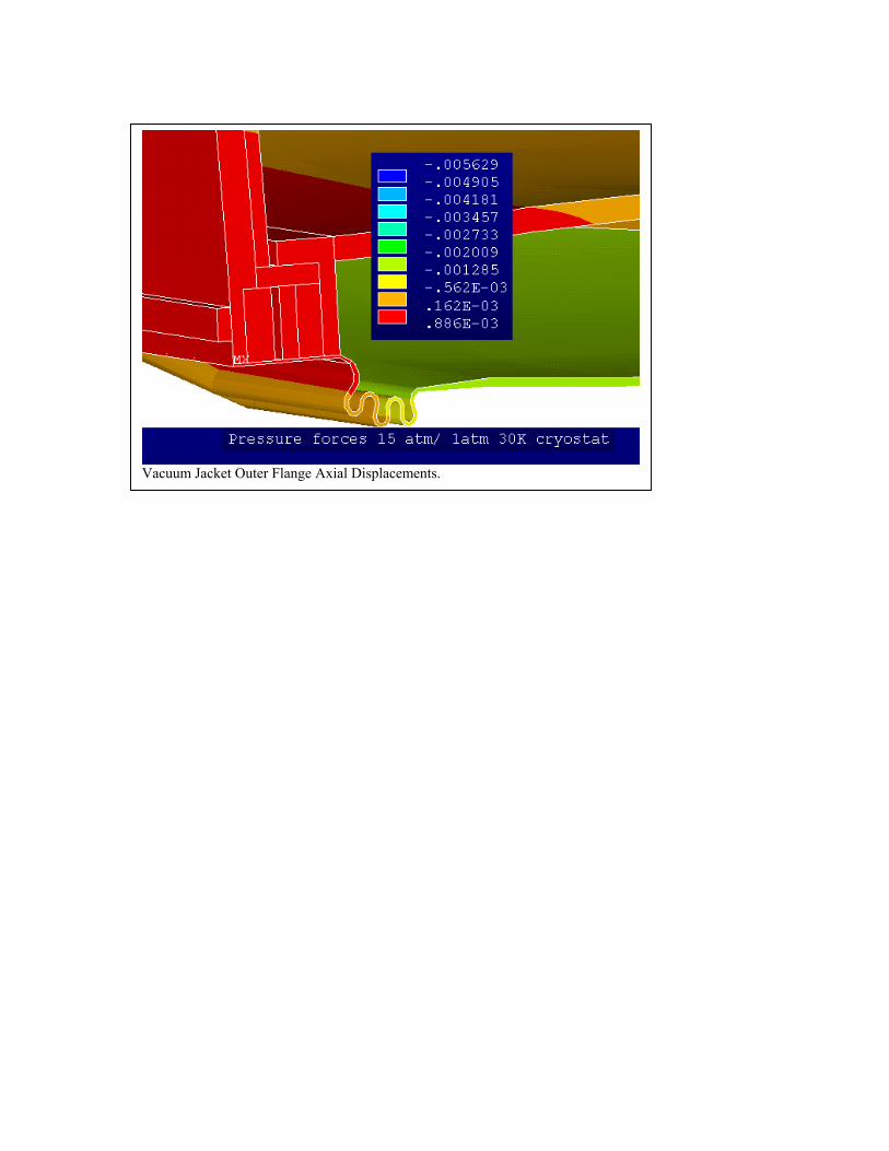
Vacuum Jacket Outer Flange Axial Displacements.
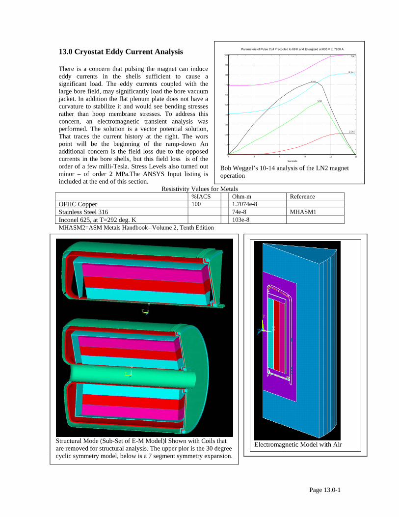
13.0 Cryostat Eddy Current Analysis There is a concern that pulsing the magnet can induce eddy currents in the shells sufficient to cause a significant load. The eddy currents coupled with the large bore field, may significantly load the bore vacuum jacket. In addition the flat plenum plate does not have a curvature to stabilize it and would see bending stresses rather than hoop membrane stresses. To address this concern, an electromagnetic transient analysis was performed. The solution is a vector potential solution, That traces the current history at the right. The wors point will be the beginning of the ramp-down An additional concern is the field loss due to the opposed currents in the bore shells, but this field loss is of the order of a few milli-Tesla. Stress Levels also turned out minor – of order 2 MPa.The ANSYS Input listing is included at the end of this section.
Resistivity Values for Metals %IACS Ohm-m Reference OFHC Copper 100 1.7074e-8 Stainless Steel 316 74e-8 MHASM1 Inconel 625, at T=292 deg. K 103e-8 MHASM2=ASM Metals Handbook--Volume 2, Tenth Edition
0
10
20
30
40
50
60
70
80
90
100
0 3 6 9 12 15
Q [MJ]
V/10
R [mΩ]
I/100
T [K]
Seconds
Parameters of Pulse Coil Precooled to 69 K and Energized at 600 V to 7200 A
Bob Weggel’s 10-14 analysis of the LN2 magnet operation
Electromagnetic Model with Air
Structural Mode (Sub-Set of E-M Model)l Shown with Coils that are removed for structural analysis. The upper plor is the 30 degree cyclic symmetry model, below is a 7 segment symmetry expansion.
Page 13.0-1
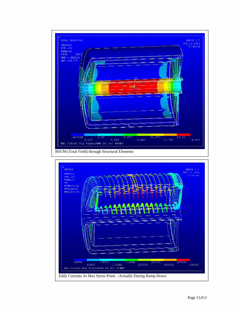
BSUM (Total Field) through Structural Elements
Eddy Currents At Max Stress Point. –Actually During Ramp-Down
Page 13.0-2
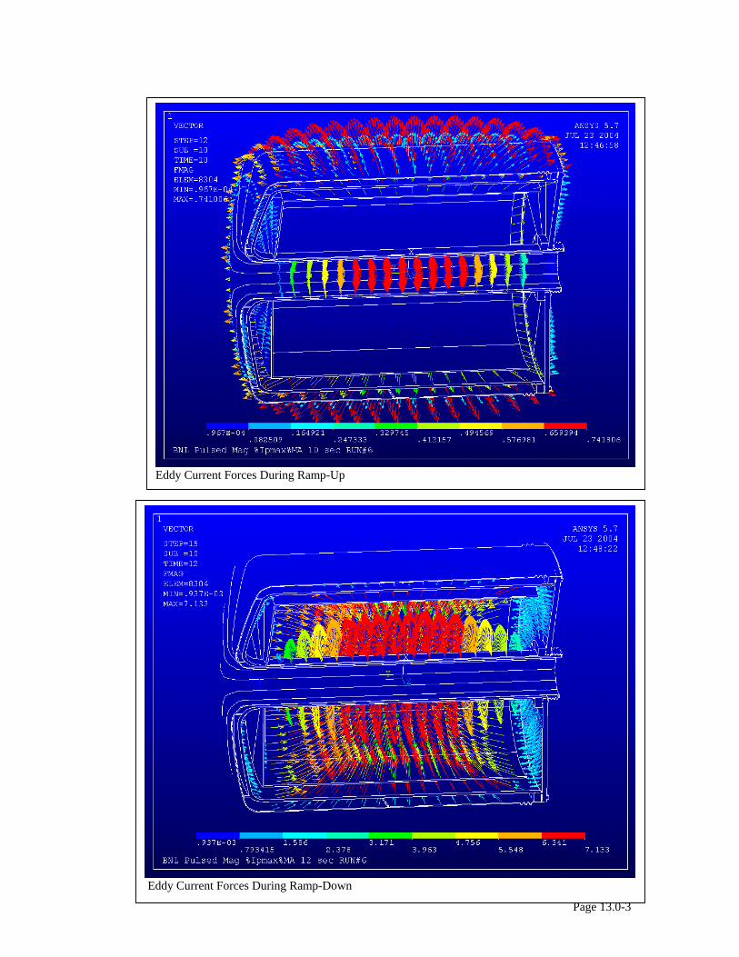
Eddy Current Forces During Ramp-Up
Page 13.0-3
Eddy Current Forces During Ramp-Down
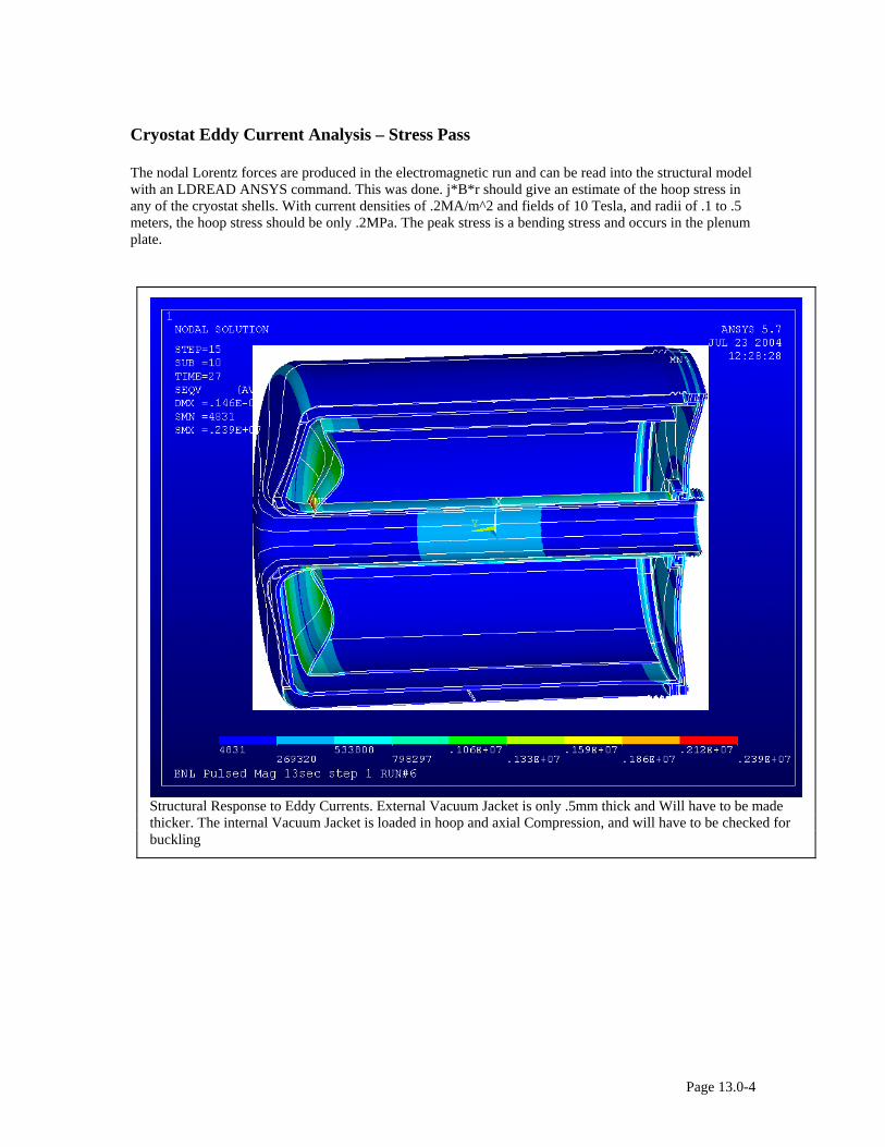
Cryostat Eddy Current Analysis – Stress Pass The nodal Lorentz forces are produced in the electromagnetic run and can be read into the structural model with an LDREAD ANSYS command. This was done. j*B*r should give an estimate of the hoop stress in any of the cryostat shells. With current densities of .2MA/m^2 and fields of 10 Tesla, and radii of .1 to .5 meters, the hoop stress should be only .2MPa. The peak stress is a bending stress and occurs in the plenum plate.
Structural Response to Eddy Currents. External Vacuum Jacket is only .5mm thick and Will have to be made thicker. The internal Vacuum Jacket is loaded in hoop and axial Compression, and will have to be checked for buckling
Page 13.0-4
/batch runn=06 /com /com ! CREATE BASE ELECTROMAGNETIC SOLUTION /filnam,elect /PREP7 antype,trans /COM 11-25-98 Electrical/Thermal analysis ET,1,97,1 ! (Ax, Ay, Az, VOLT) EM for current regions ET,2,97,0 ! (Ax, Ay, Az) EM for air ET,3,97,0 ! (Ax, Ay, Az) EM for air TREF,292.0 *create,matt /COM MAT,1 Coil /COM MAT,3 COIL /COM MAT,5 Coil /com MAT,2 Channel /com MAT,4 Channel /com MAT,6 Channel /com MAT,7 Bore tube /com MAT,10 packf=.9 mp,dens,1,8950 mp,dens,2,8950 mp,dens,3,8950 mp,dens,4,8950 mp,dens,5,8950 mp,dens,6,8950 mp,dens,7,4000 mp,dens,90,.0000001 mp,dens,91,.0000001 mp,dens,92,.0000001 mp,murx,1,1.0 mp,murx,2,1.0 mp,murx,3,1.0 mp,murx,4,1.0 mp,murx,5,1.0 mp,murx,6,1.0 mp,murx,7,1.0 mp,murx,8,1.0 mp,murx,9,1.0 mp,murx,10,1.0 mp,murx,11,1.0 mp,murx,12,1.0 mp,murx,13,1.0 mp,murx,14,1.0 mp,murx,90,1.0 mp,murx,91,1.0 mp,murx,92,1.0 mp,kxx,1,1 mp,kxx,2,1 mp,kxx,3,.000001 mp,kxx,4,1 mp,kxx,5,1 mp,kxx,6,1 mp,rsvx,1,0.0 mp,rsvx,2,0.0 mp,rsvx,3,0.0 mp,rsvx,4,0.0 mp,rsvx,5,0.0 mp,rsvx,6,0.0 mp,rsvx,7,0.0 ! G-10 Bore liner mp,rsvx,8,74e-8
mp,rsvx,9,74e-8 mp,rsvx,10,74e-8 mp,rsvx,11,74e-8 mp,rsvx,12,74e-8 mp,rsvx,13,74e-8 mp,rsvx,14,74e-8 mp,rsvx,15,74e-8 mp,rsvx,90,0.0 mp,rsvx,91,0.0 mp,rsvx,92,0.0 mp,c,1,100 mp,c,2,100 mp,c,3,100 mp,c,4,100 mp,c,5,100 mp,c,6,100 mp,c,7,100 mp,c,10,100 mp,c,11,100 mp,c,12,100 mp,c,13,100 mp,c,14,100 mp,c,15,100 mp,c,90,1.0 mp,c,91,1.0 mp,c,92,1.0 *end *use,matt /com /input,vma6,mod /com nall eall LOCAL,12,1,0,0,0,0,-90.0,0.0 CSYS,12 $NROTAT,all esys,12 /com Coupled Flux Condition nsel,x,.99,2.5 d,all,ax,0.0 ! Added 2-2-98 d,all,ay,0.0 d,all,az,0.0 nsel,z,1.75,2 nasel,z,-2.0,-1.75 d,all,ax,0.0 d,all,ay,0.0 d,all,az,0.0 !added 2-2-98 nsel,x,0,.011 nasel,x,1.499,1.501 d,all,ay,0.0 d,all,az,0.0 nall eall esel,type,1 nelem nrsel,y,-16,-14 d,all,volt,0.0 esel,type,1 nelem nrsel,y,14,16 d,all,volt,0.0 nall eall csys,0 Wsort,x wsort,y
Page 13.0-5
wsort,z tunif,80 csys,0 curd= .01 esel,mat,1 easel,mat,3 easel,mat,5 nelem bfe,all,js,1,0,0,curd eall nall save fini /solu Transient Current Parameters t1= 0.100000 $i1= 10.0 $p1= .01e6 t2= 1.00000 $i2= 800.0 $p2= 1.0e6 t3= 2.000000 $i3= 2000.0 $p3= 1.0e6 t4= 3.0000 $i4=3100.0 $p4= 1.5e6 t5= 4.00000 $i5=4000.0 $p5= 1.0e6 t6= 5.0000 $i6= 4900.0 $p6= .5e6 t7= 6.0000 $i7= 5650.0 $p7= .001e6 t8= 7.00000 $i8= 6200.0 $p8= 0.0e6 t9= 8.00000 $i9= 6700.0 $p9= 0.0e6 t10=9.00000 $i10= 7050.0 $p1= 0.0e6 t11=10.00000 $i11= 7200.0 $p1= 0.0e6 t12=10.50000 $i12= 7200.0 $p1= 0.0e6 t13=11.00000 $i13= 6900.0 $p1= 0.0e6 t14=12.00000 $i14= 4800.0 $p1= 0.0e6 t15=13.00000 $i15= 3000.0 $p1= 0.0e6 nsubst,10,10,3 time,.01 /com Elecromagnetic Solution estep=estep+1 solve save ! SETUP TRANSIENT MACRO *create,load /com solve electromagnetic problem time,timpt csys,0 curd= i%ls%*6375 esel,mat, 1 easel,mat, 3 easel,mat, 5 bfe,all,js,1,0,0,curd eall nall solve save *end ! START TRANSIENT *do,ls,1,15,1 timpt=t%ls% curamp=i%ls% /TITLE, BNL Pulsed Mag %Ipmax%MA %timpt% sec RUN#%runn% *use,load *enddo fini /filnam,stru /prep7 antype,static
/TITLE, BNL Pulsed Mag %timpt%sec step %estep% RUN#%runn% et,1,45 et,2,45 ex,1,70e9 ex,2,70e9 ex,3,70e9 ex,4,70e9 ex,5,70e9 ex,6,70e9 ex,7,70e9 ex,8,70e9 ex,9,70e9 ex,10,200e9 ex,11,200e9 ex,12,200e9 ex,13,200e9 ex,14,200e9 LOCAL,12,1,0,0,0,0,-90.0,0.0 CSYS,12 $NROTAT,all nsel,y,-16,-14.99 nasel,y,14.99,16 d,all,uy,0.0 nsel,z,-.006,.006 d,all,uz,0.0 nall eall save fini /solu *do,ldnum,1,15 ldread,forc,ldnum,,,,elect,rst eusel,mat,90 eusel,mat,91 eusel,mat,92 eusel,mat,1 eusel,mat,2 eusel,mat,3 eusel,mat,4 eusel,mat,5 eusel,mat,7 nelem solve *enddo save fini /exit
Page 13.0-6
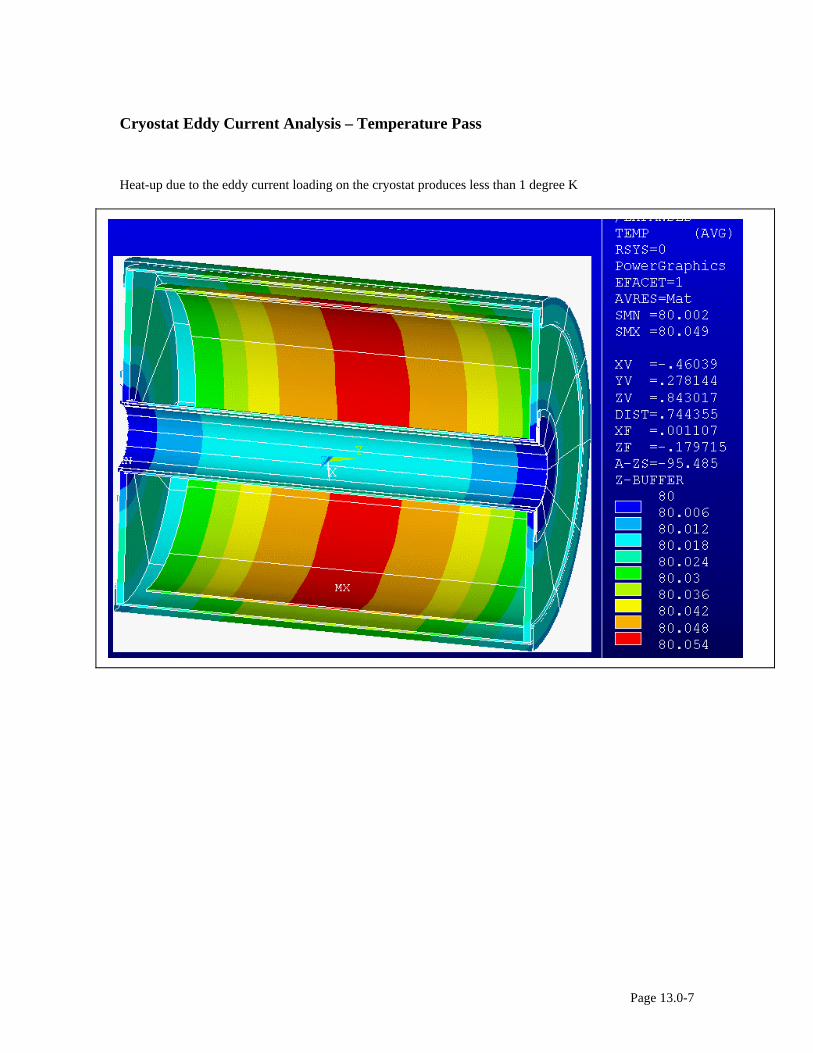
Cryostat Eddy Current Analysis – Temperature Pass
Heat-up due to the eddy current loading on the cryostat produces less than 1 degree K
Page 13.0-7
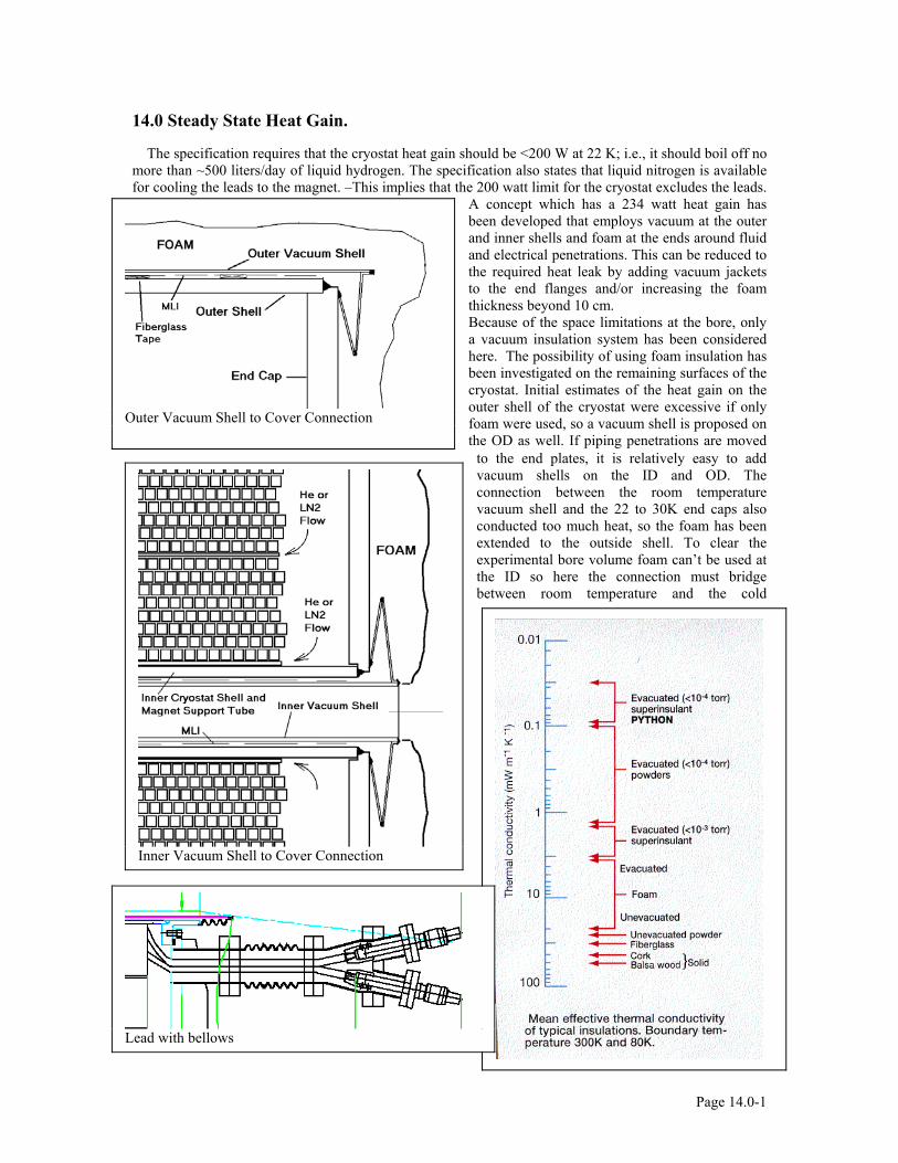
14.0 Steady State Heat Gain.
The specification requires that the cryostat heat gain should be <200 W at 22 K; i.e., it should boil off no more than ~500 liters/day of liquid hydrogen. The specification also states that liquid nitrogen is available for cooling the leads to the magnet. –This implies that the 200 watt limit for the cryostat excludes the leads.
A concept which has a 234 watt heat gain has been developed that employs vacuum at the outer and inner shells and foam at the ends around fluid and electrical penetrations. This can be reduced to the required heat leak by adding vacuum jackets to the end flanges and/or increasing the foam thickness beyond 10 cm.
Outer Vacuum Shell to Cover Connection
Because of the space limitations at the bore, only a vacuum insulation system has been considered here. The possibility of using foam insulation has been investigated on the remaining surfaces of the cryostat. Initial estimates of the heat gain on the outer shell of the cryostat were excessive if only foam were used, so a vacuum shell is proposed on the OD as well. If piping penetrations are moved
to the end plates, it is relatively easy to add vacuum shells on the ID and OD. The connection between the room temperature vacuum shell and the 22 to 30K end caps also conducted too much heat, so the foam has been extended to the outside shell. To clear the experimental bore volume foam can’t be used at the ID so here the connection must bridge between room temperature and the cold
Inner Vacuum Shell to Cover Connection
Lead with bellows
Page 14.0-1
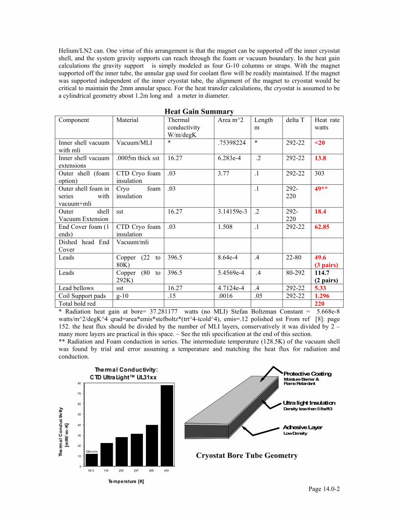
Helium/LN2 can. One virtue of this arrangement is that the magnet can be supported off the inner cryostat shell, and the system gravity supports can reach through the foam or vacuum boundary. In the heat gain calculations the gravity support is simply modeled as four G-10 columns or straps. With the magnet supported off the inner tube, the annular gap used for coolant flow will be readily maintained. If the magnet was supported independent of the inner cryostat tube, the alignment of the magnet to cryostat would be critical to maintain the 2mm annular space. For the heat transfer calculations, the cryostat is assumed to be a cylindrical geometry about 1.2m long and a meter in diameter.
Heat Gain Summary Component Material Thermal
conductivity W/m/degK
Area m^2 Length m
delta T Heat rate watts
Inner shell vacuum with mli
Vacuum/MLI * .75398224 * 292-22 <20
Inner shell vacuum extensions
.0005m thick sst 16.27 6.283e-4
.2 292-22 13.8
Outer shell (foam option)
CTD Cryo foam insulation
.03 3.77 .1 292-22 303
Outer shell foam in series with vacuum+mli
Cryo foam insulation
.03 .1 292-220
49**
Outer shell Vacuum Extension
sst 16.27 3.14159e-3
.2 292-220
18.4
End Cover foam (1 ends)
CTD Cryo foam insulation
.03 1.508 .1 292-22 62.85
Dished head End Cover
Vacuum/mli
Leads Copper (22 to 80K)
396.5 8.64e-4 .4 22-80 49.6 (3 pairs)
Leads Copper (80 to 292K)
396.5 5.4569e-4 .4 80-292 114.7 (2 pairs)
Lead bellows sst 16.27 4.7124e-4 .4 292-22 5.33 Coil Support pads g-10 .15 .0016 .05 292-22 1.296 Total bold red 220 * Radiation heat gain at bore= 37.281177 watts (no MLI) Stefan Boltzman Constant = 5.668e-8 watts/m^2/degK^4 qrad=area*emis*stefboltz*(trt^4-tcold^4), emis=.12 polished sst From ref [8]: page 152. the heat flux should be divided by the number of MLI layers, conservatively it was divided by 2 – many more layers are practical in this space. – See the mli specification at the end of this section. ** Radiation and Foam conduction in series. The intermediate temperature (128.5K) of the vacuum shell was found by trial and error assuming a temperature and matching the heat flux for radiation and conduction.
Adhesive Layer
Ultra light Insulation
Protective CoatingMoisture Barrier & Flame Retardant
Density less than 5 lbs/ft3
Low Density
88.5 144 200 297 366 4500
10
20
30
40
50
60
70
80
Thermal Conductivity: CTD UltraLight™ UL31xx
Te mperature [K]
The
rmal
Con
duc
tivity
[m
W/m
-K]
Estimate
Cryostat Bore Tube Geometry
Page 14.0-2
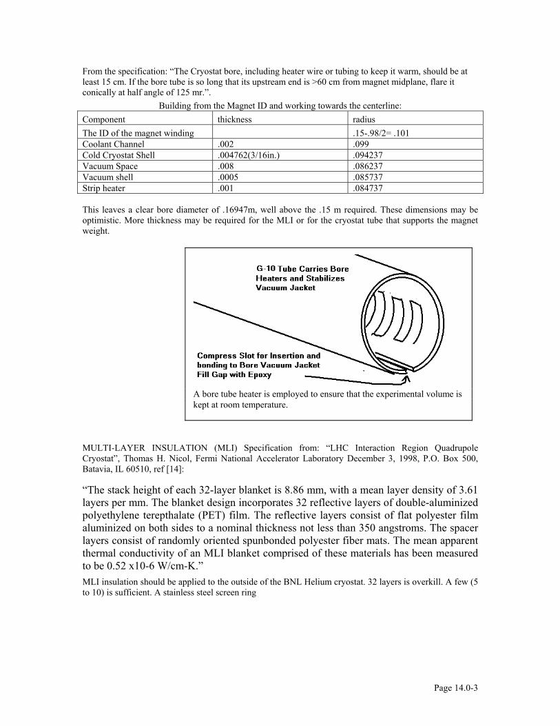
From the specification: “The Cryostat bore, including heater wire or tubing to keep it warm, should be at least 15 cm. If the bore tube is so long that its upstream end is >60 cm from magnet midplane, flare it conically at half angle of 125 mr.”.
Building from the Magnet ID and working towards the centerline: Component thickness radius The ID of the magnet winding .15-.98/2= .101 Coolant Channel .002 .099 Cold Cryostat Shell .004762(3/16in.) .094237 Vacuum Space .008 .086237 Vacuum shell .0005 .085737 Strip heater .001 .084737 This leaves a clear bore diameter of .16947m, well above the .15 m required. These dimensions may be optimistic. More thickness may be required for the MLI or for the cryostat tube that supports the magnet weight.
A bore tube heater is employed to ensure that the experimental volume is kept at room temperature.
MULTI-LAYER INSULATION (MLI) Specification from: “LHC Interaction Region Quadrupole Cryostat”, Thomas H. Nicol, Fermi National Accelerator Laboratory December 3, 1998, P.O. Box 500, Batavia, IL 60510, ref [14]:
“The stack height of each 32-layer blanket is 8.86 mm, with a mean layer density of 3.61 layers per mm. The blanket design incorporates 32 reflective layers of double-aluminized polyethylene terepthalate (PET) film. The reflective layers consist of flat polyester film aluminized on both sides to a nominal thickness not less than 350 angstroms. The spacer layers consist of randomly oriented spunbonded polyester fiber mats. The mean apparent thermal conductivity of an MLI blanket comprised of these materials has been measured to be 0.52 x10⁻⁶ W/cm-K.” MLI insulation should be applied to the outside of the BNL Helium cryostat. 32 layers is overkill. A few (5 to 10) is sufficient. A stainless steel screen ring
Page 14.0-3

Page 14.0-4
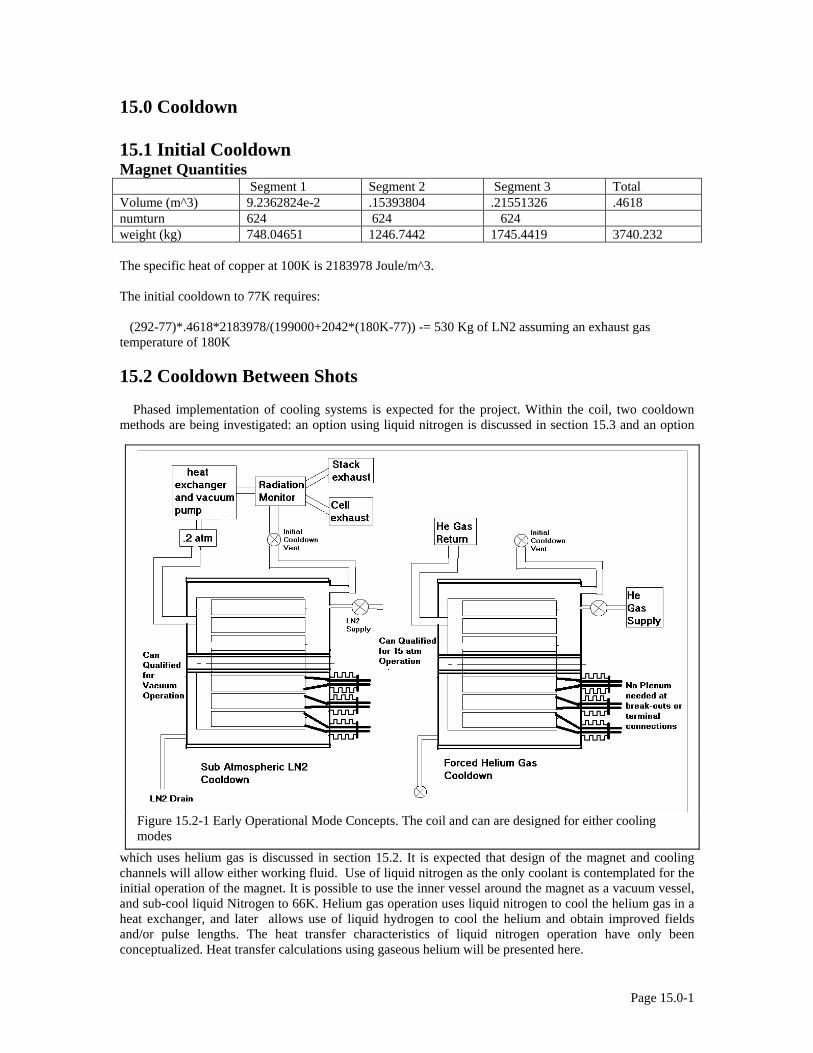
15.0 Cooldown 15.1 Initial Cooldown Magnet Quantities Segment 1 Segment 2 Segment 3 Total Volume (m^3) 9.2362824e-2 .15393804 .21551326 .4618 numturn 624 624 624 weight (kg) 748.04651 1246.7442 1745.4419 3740.232 The specific heat of copper at 100K is 2183978 Joule/m^3. The initial cooldown to 77K requires: (292-77)*.4618*2183978/(199000+2042*(180K-77)) -= 530 Kg of LN2 assuming an exhaust gas temperature of 180K 15.2 Cooldown Between Shots Phased implementation of cooling systems is expected for the project. Within the coil, two cooldown methods are being investigated: an option using liquid nitrogen is discussed in section 15.3 and an option
which uses helium gas is discussed in section 15.2. It is expected that design of the magnet and cooling channels will allow either working fluid. Use of liquid nitrogen as the only coolant is contemplated for the initial operation of the magnet. It is possible to use the inner vessel around the magnet as a vacuum vessel, and sub-cool liquid Nitrogen to 66K. Helium gas operation uses liquid nitrogen to cool the helium gas in a heat exchanger, and later allows use of liquid hydrogen to cool the helium and obtain improved fields and/or pulse lengths. The heat transfer characteristics of liquid nitrogen operation have only been conceptualized. Heat transfer calculations using gaseous helium will be presented here.
Figure 15.2-1 Early Operational Mode Concepts. The coil and can are designed for either cooling modes
Page 15.0-1
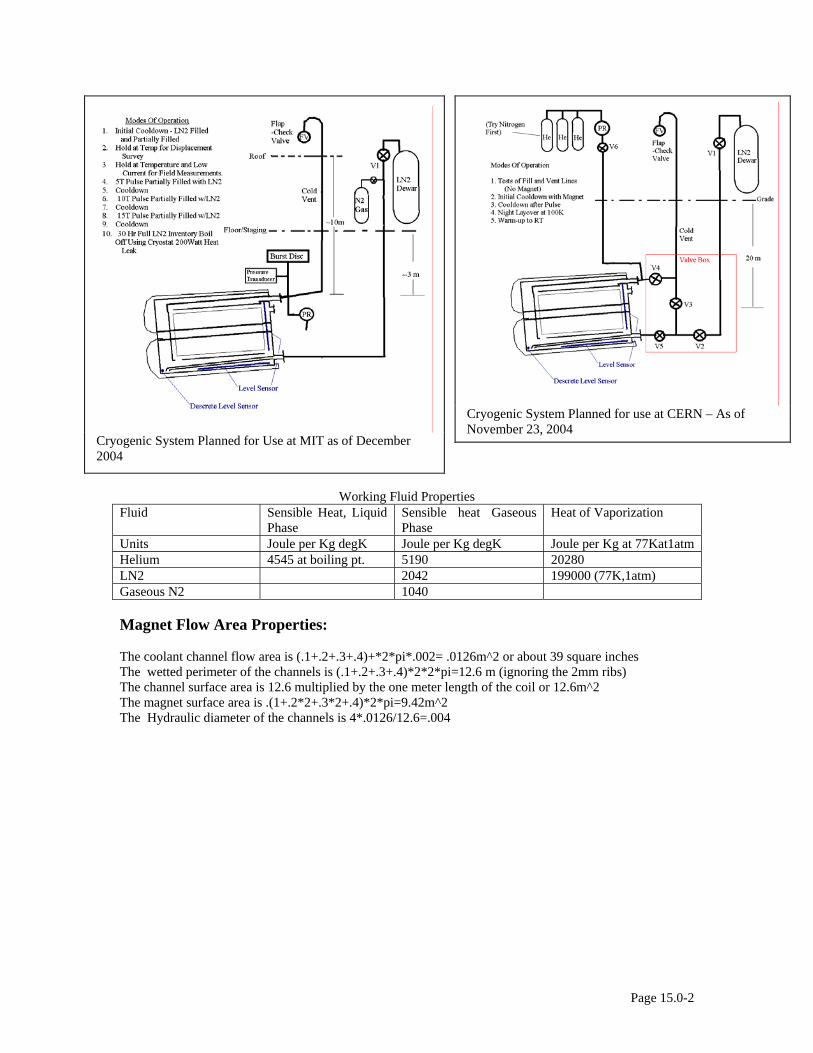
Cryogenic System Planned for Use at MIT as of December 2004
Cryogenic System Planned for use at CERN – As of November 23, 2004
Working Fluid Properties Fluid Sensible Heat, Liquid
Phase Sensible heat Gaseous Phase
Heat of Vaporization
Units Joule per Kg degK Joule per Kg degK Joule per Kg at 77Kat1atm Helium 4545 at boiling pt. 5190 20280 LN2 2042 199000 (77K,1atm) Gaseous N2 1040 Magnet Flow Area Properties: The coolant channel flow area is (.1+.2+.3+.4)+*2*pi*.002= .0126m^2 or about 39 square inches The wetted perimeter of the channels is (.1+.2+.3+.4)*2*2*pi=12.6 m (ignoring the 2mm ribs) The channel surface area is 12.6 multiplied by the one meter length of the coil or 12.6m^2 The magnet surface area is .(1+.2*2+.3*2+.4)*2*pi=9.42m^2 The Hydraulic diameter of the channels is 4*.0126/12.6=.004
Page 15.0-2
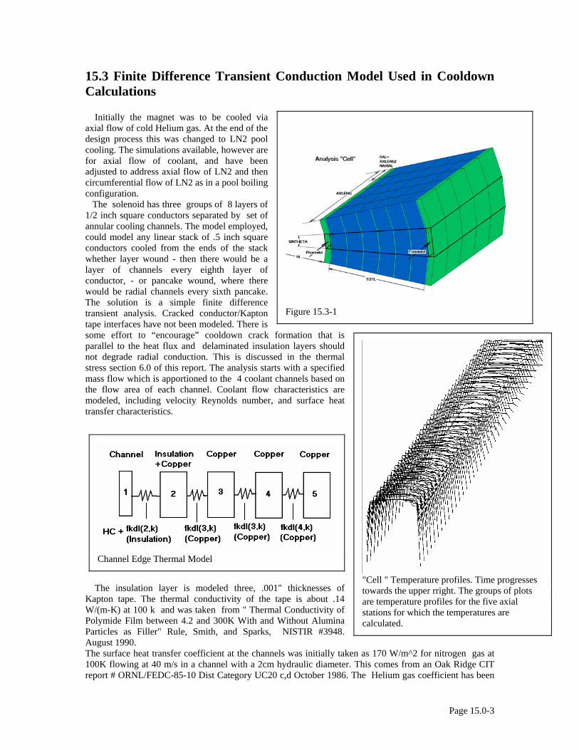
15.3 Finite Difference Transient Conduction Model Used in Cooldown Calculations Initially the magnet was to be cooled via axial flow of cold Helium gas. At the end of the design process this was changed to LN2 pool cooling. The simulations available, however are for axial flow of coolant, and have been adjusted to address axial flow of LN2 and then circumferential flow of LN2 as in a pool boiling configuration. The solenoid has three groups of 8 layers of 1/2 inch square conductors separated by set of annular cooling channels. The model employed, could model any linear stack of .5 inch square conductors cooled from the ends of the stack whether layer wound - then there would be a layer of channels every eighth layer of conductor, - or pancake wound, where there would be radial channels every sixth pancake. The solution is a simple finite difference transient analysis. Cracked conductor/Kapton tape interfaces have not been modeled. There is some effort to “encourage” cooldown crack formation that is parallel to the heat flux and delaminated insulation layers should not degrade radial conduction. This is discussed in the thermal stress section 6.0 of this report. The analysis starts with a specified mass flow which is apportioned to the 4 coolant channels based on the flow area of each channel. Coolant flow characteristics are modeled, including velocity Reynolds number, and surface heat transfer characteristics.
The insulation layer is modeled three, .001" thicknesses of Kapton tape. The thermal conductivity of the tape is about .14 W/(m-K) at 100 k and was taken from " Thermal Conductivity of Polymide Film between 4.2 and 300K With and Without Alumina Particles as Filler" Rule, Smith, and Sparks, NISTIR #3948. August 1990.
Figure 15.3-1
"Cell " Temperature profiles. Time progresses towards the upper rright. The groups of plots are temperature profiles for the five axial stations for which the temperatures are calculated.
Channel Edge Thermal Model
The surface heat transfer coefficient at the channels was initially taken as 170 W/m^2 for nitrogen gas at 100K flowing at 40 m/s in a channel with a 2cm hydraulic diameter. This comes from an Oak Ridge CIT report # ORNL/FEDC-85-10 Dist Category UC20 c,d October 1986. The Helium gas coefficient has been
Page 15.0-3

calculated from the Nusselt, Reynolds, and Prandle Numbers using the relation quoted in the Oak Ridge document, which is a more generic heat transfer coefficient correlation, and is good for ideal gasses.
Page 15.0-4
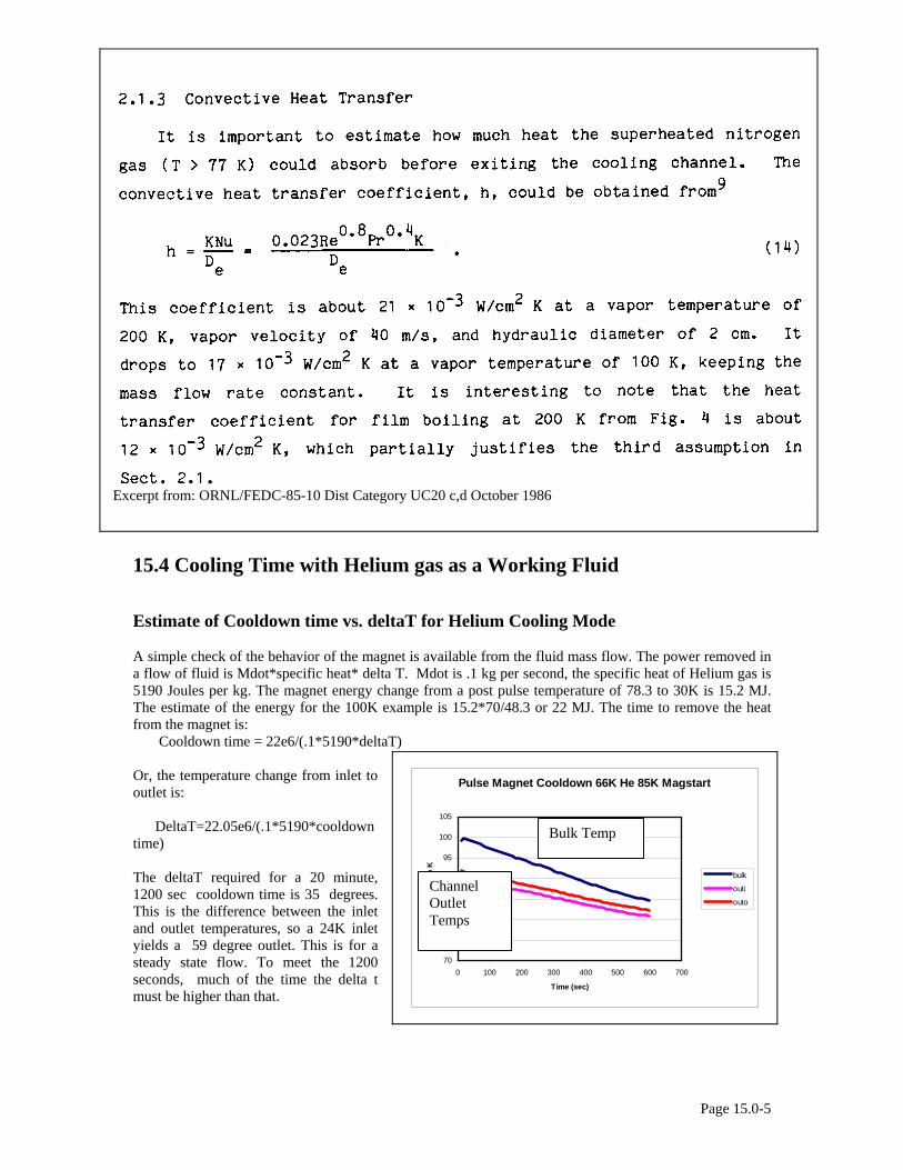
Excerpt from: ORNL/FEDC-85-10 Dist Category UC20 c,d October 1986
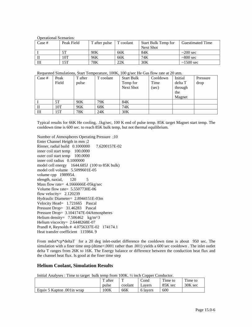
15.4 Cooling Time with Helium gas as a Working Fluid Estimate of Cooldown time vs. deltaT for Helium Cooling Mode A simple check of the behavior of the magnet is available from the fluid mass flow. The power removed in a flow of fluid is Mdot*specific heat* delta T. Mdot is .1 kg per second, the specific heat of Helium gas is 5190 Joules per kg. The magnet energy change from a post pulse temperature of 78.3 to 30K is 15.2 MJ. The estimate of the energy for the 100K example is 15.2*70/48.3 or 22 MJ. The time to remove the heat from the magnet is: Cooldown time = 22e6/(.1*5190*deltaT) Or, the temperature change from inlet to outlet is: DeltaT=22.05e6/(.1*5190*cooldown time) The deltaT required for a 20 minute, 1200 sec cooldown time is 35 degrees. This is the difference between the inlet and outlet temperatures, so a 24K inlet yields a 59 degree outlet. This is for a steady state flow. To meet the 1200 seconds, much of the time the delta t must be higher than that.
Pulse Magnet Cooldown 66K He 85K Magstart
70
75
80
85
90
Tem
pera
tur
95
100
105
0 100 200 300 400 500 600 700
Time (sec)
e K
bulk
outi
outo
Bulk Temp
Channel Outlet Temps
Page 15.0-5
Operational Scenarios: Case # Peak Field T after pulse T coolant Start Bulk Temp for
Next Shot Guestimated Time
I 5T 90K 66K 84K ~200 sec II 10T 96K 66K 74K ~800 sec III 15T 78K 22K 30K ~1500 sec Requested Simulations, Start Temperature, 100K, 100 g/sec He Gas flow rate at 20 atm. Case # Peak
Field T after pulse
T coolant Start Bulk Temp for Next Shot
Cooldown Time (sec)
Initial delta T through the Magnet
Pressure drop
I 5T 90K 79K 84K II 10T 96K 68K 74K III 15T 78K 24K 30K Typical results for 66K He cooling, .1kg/sec, 100 K end of pulse temp. 85K target Magnet start temp. The cooldown time is 600 sec. to reach 85K bulk temp, but not thermal equilibrium. Number of Atmospheres Operating Pressure ;10 Enter Channel Heigth in mm ;2 Rinner, radial build 0.1000000 7.6200157E-02 inner coil start temp 100.0000 outer coil start temp 100.0000 inner coil radius 0.1000000 model cell energy 1644.685J (100 to 85K bulk) model cell volume 5.5099601E-05 volume cpp 1989954. nlength, naxial, 120 5 Mass flow rate= 4.1666666E-05kg/sec Volume flow rate= 5.5507730E-06 flow velocity= 2.120239 Hydraulic Diameter= 2.8944151E-03m Velocity Head= 1.721665 Pascal Pressure Drop= 31.46283 Pascal Pressure Drop= 3.1041747E-04Atmospheres Helium density= 7.506462 kg/m^3 Helium viscocity= 2.6448268E-07 Prandl #, Reynolds # 4.0756337E-02 174174.1 Heat transfer coefficient 115984. 9 From mdot*cp*deltaT for a 20 deg inlet-outlet difference the cooldown time is about 950 sec. The simulation with a finer time step (dtime=.0001 rather than .001) yields a 600 sec cooldown . The inlet outlet delta T ranges from 26K to 16K. The Energy balance or difference between the conduction heat flux and the channel heat flux. Is good at the finer time step Helium Coolant, Simulation Results Initial Analyses : Time to target bulk temp from 100K. ½ inch Copper Conductor. T after
pulse T coolant
Cond Layers
Time to 85K sec
Time to 30K sec
Equiv 5 Kapton .001in wrap 100K 66K 6 layers 600
Page 15.0-6
Equiv 5 Kapton .001in wrap 100K 66K 8 layers >850 Equiv 3 Kapton .001in wrap 100K 66K 8 layers 450 Equiv 5 kapton .0001in wrap 100K 30K 6 Layers 2000 M dot
Time Step (sec)
Initial Temp
Final Temp
Tcool Time to cool down (sec.)
Tend-Tstart
Excel File
.1 30 100 30 2000 70 (early#1)
.1 .001 74 100 67 2100 26 hegas1.xls
.1 .0001 53 78 20 570 25 Hegas7.xls
.1 .001 53 78 20 790 25
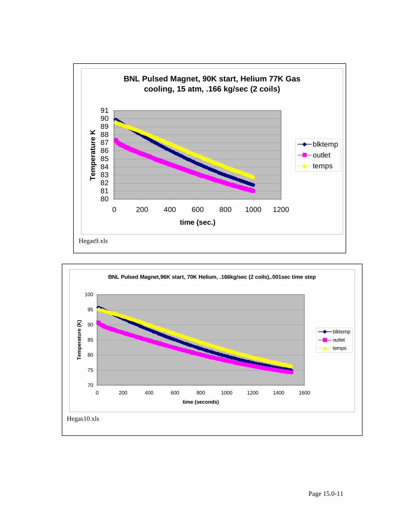
.1 .001 84 90 77 1000 6 hegas3.xls .1 .001 74 100 67 2100 26 hegas1.xls .1 .0001 74 100 67 2100 26 Hegas8.xls .1 .0001 80 100 67 1470 20 Hegas8.xls .1 .0001 30 78 20 1100 48 Hegas7.xls .1666 .001 84 90 77 650 Hegas9.xls .1666 .001 74 96 70 1600 Hegas10.xls .1666 .001 74 96 70 1670 22 hegas5.xls .1666 .001 74 100 67 1600 26 hegas2.xls .1666 .001 84 90 77 660 6 hegas4.xls
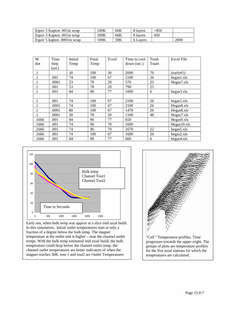
"Cell " Temperature profiles. Time progresses towards the upper rright. The groups of plots are temperature profiles for the five axial stations for which the temperatures are calculated.
0
20
40
60
80
100
120
0 500 1000 1500 2000 2500
blktempeout1eout2
Early run, when bulk temp was approx at a slice mid axial build. In this simulation, Initial outlet temperatures start at only a fraction of a degree below the bulk temp. The magnet temperature at the outlet end is higher – near the channel outlet temps. With the bulk temp estimated mid axial build, the bulk temperature could drop below the channel outlet temp. the channel outlet temperatures are better indicators of when the magnet reaches 30K. tout 1 and tout2 are Outlet Temperatures
Bulk temp Channel Tout1 Channel Tout2
Time in Seconds
Page 15.0-7
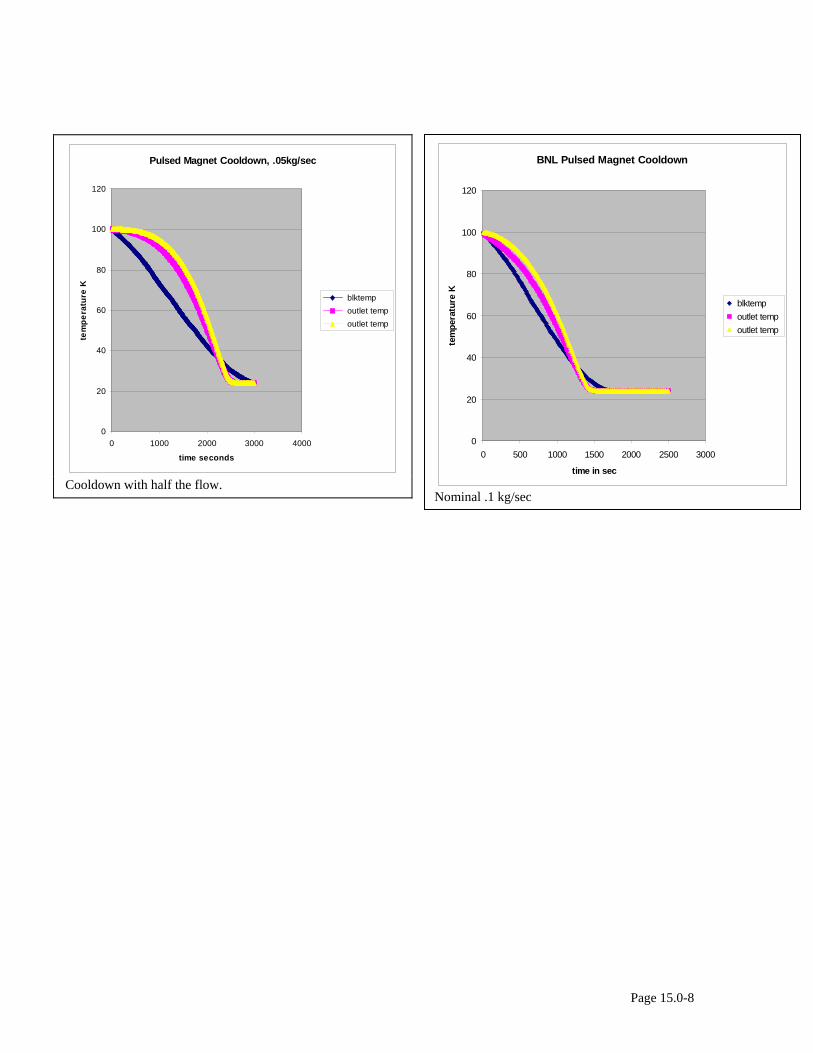
Pulsed Magnet Cooldown, .05kg/sec
0
20
40
60
80
100
120
0 1000 2000 3000 4000
time seconds
tem
pera
ture
K
blktemp outlet temp outlet temp
Cooldown with half the flow.
BNL Pulsed Magnet Cooldown
0
20
40
60
80
100
120
0 500 1000 1500 2000 2500 3000
time in sec
tem
pera
ture
K
blktemp outlet temp outlet temp
Nominal .1 kg/sec
Page 15.0-8
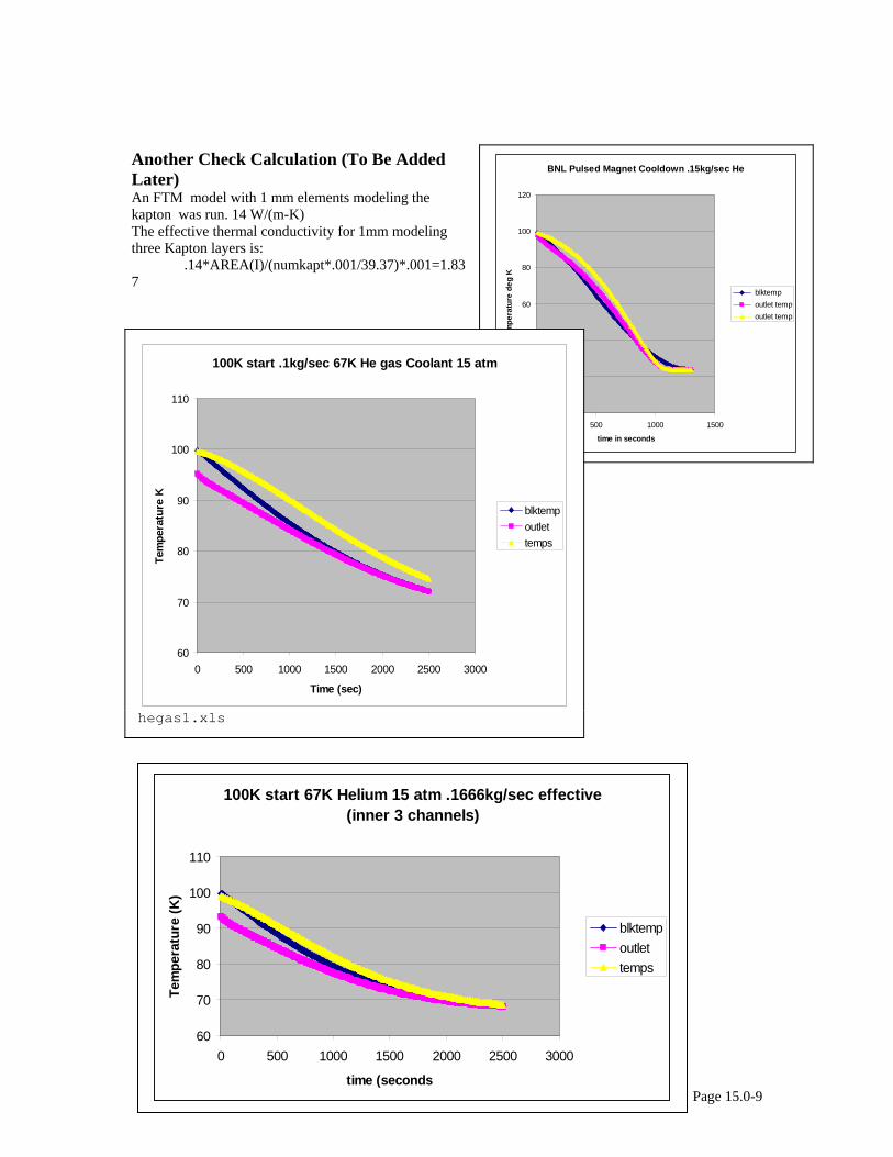
Another Check Calculation (To Be Added Later) An FTM model with 1 mm elements modeling the kapton was run. 14 W/(m-K) The effective thermal conductivity for 1mm modeling three Kapton layers is: .14*AREA(I)/(numkapt*.001/39.37)*.001=1.837
Page 15.0-9
BNL Pulsed Magnet Cooldown .15kg/sec He
0
20
40
60
80
100
120
0 500 1000 1500
time in seconds
tem
pera
ture
deg
K
blktemp outlet temp outlet temp
100K start .1kg/sec 67K He gas Coolant 15 atm
60
70
80
90
100
110
0 500 1000 1500 2000 2500 3000
Time (sec)
Tem
pera
ture
K
blktempoutlettemps
hegas1.xls
100K start 67K Helium 15 atm .1666kg/sec effective (inner 3 channels)
60
70
80
90
100
110
0 500 1000 1500 2000 2500 3000
time (seconds
Tem
pera
ture
(K)
blktempoutlettemps
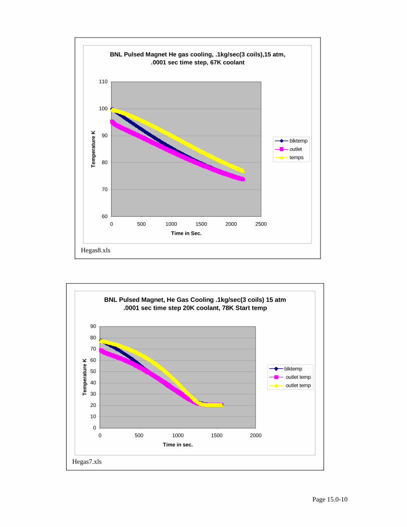
BNL Pulsed Magnet He gas cooling, .1kg/sec(3 coils),15 atm, .0001 sec time step, 67K coolant
60
70
80
90
100
110
0 500 1000 1500 2000 2500
Time in Sec.
Tem
pera
ture
K
blktempoutlettemps
Hegas8.xls
BNL Pulsed Magnet, He Gas Cooling .1kg/sec(3 coils) 15 atm .0001 sec time step 20K coolant, 78K Start temp
0
10
20
30
40
50
60
70
80
90
0 500 1000 1500 2000
Time in sec.
Tem
pera
ture
K
blktemp outlet temp outlet temp
Hegas7.xls
Page 15.0-10
BNL Pulsed Magnet, 90K start, Helium 77K Gas cooling, 15 atm, .166 kg/sec (2 coils)
808182838485868788899091
0 200 400 600 800 1000 1200
time (sec.)
Tem
pera
ture
K
blktempoutlettemps
Hegas9.xls
BNL Pulsed Magnet,96K start, 70K Helium, .166kg/sec (2 coils),.001sec time step
70
75
80
85
90
95
100
0 200 400 600 800 1000 1200 1400 1600
time (seconds)
Tem
pera
ture
(K)
blktempoutlettemps
Hegas10.xls
Page 15.0-11
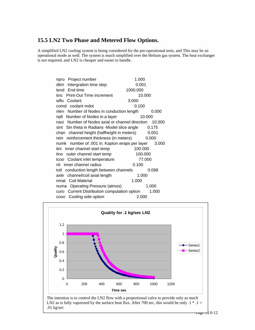
15.5 LN2 Two Phase and Metered Flow Options. A simplified LN2 cooling system is being considered for the pre-operational tests, and This may be an operational mode as well. The system is much simplified over the Helium gas system. The heat exchanger is not required, and LN2 is cheaper and easier to handle.
npro Project number 1.000 dtim Intergration time step 0.001 tend End time 1000.000 tinc Print-Out Time increment 10.000 wflu Coolant 3.000 comd coolant mdot 0.100 nlen Number of Nodes in conduction length 0.000 npll Number of Nodes in a layer 10.000 naxi Number of Nodes axial or channel direction 10.000 sint Sin theta in Radians -Model slice angle 0.175 chan channel height (halfheight in meters) 0.001 rein reinforcement thickness (in meters) 0.000 numk number of .001 in. Kapton wraps per layer 3.000 tini inner channel start temp 100.000 tino outer channel start temp 100.000 tcoo Coolant inlet temperature 77.000 riii inner channel radius 0.100 totl conduction length between channels 0.098 axle channel/coil axial length 1.000 nmat Coil Material 1.000 numa Operating Pressure (atmos) 1.000 curo Current Distribution computation option 1.000 cooo Cooling side option 2.000
Page 15.0-12
Quality for .1 kg/sec LN2
0
0.2
0.4
0.6
0.8
1
1.2
0 200 400 600 800 1000 1200
Time sec
Qua
lity Series1
Series2
The intention is to control the LN2 flow with a proportional valve to provide only as much LN2 as is fully vaporized by the surface heat flux. After 700 sec, this would be only .1 * .1 = .01 kg/sec
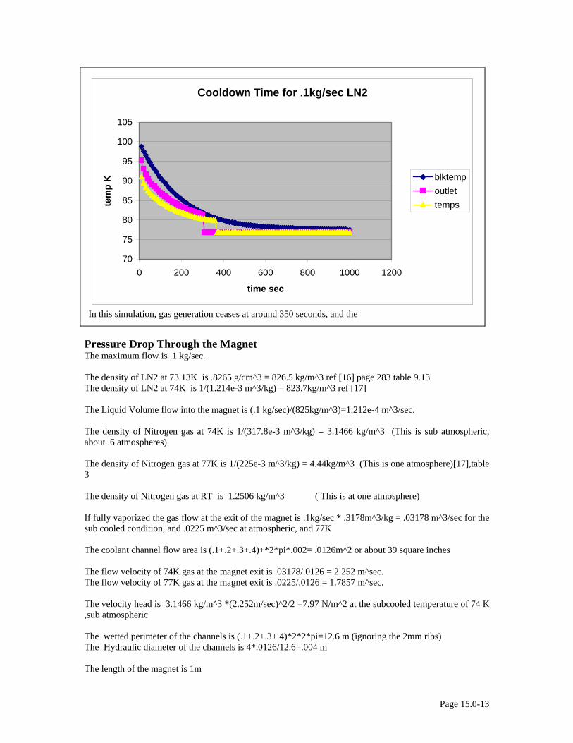
Cooldown Time for .1kg/sec LN2
70
75
80
85
90
95
100
105
0 200 400 600 800 1000 1200
time sec
tem
p K blktemp
outlettemps
In this simulation, gas generation ceases at around 350 seconds, and the
Pressure Drop Through the Magnet The maximum flow is .1 kg/sec. The density of LN2 at 73.13K is .8265 g/cm^3 = 826.5 kg/m^3 ref [16] page 283 table 9.13 The density of LN2 at 74K is 1/(1.214e-3 m^3/kg) = 823.7kg/m^3 ref [17] The Liquid Volume flow into the magnet is (.1 kg/sec)/(825kg/m^3)=1.212e-4 m^3/sec. The density of Nitrogen gas at 74K is 1/(317.8e-3 m^3/kg) = 3.1466 kg/m^3 (This is sub atmospheric, about .6 atmospheres) The density of Nitrogen gas at 77K is 1/(225e-3 m^3/kg) = 4.44kg/m^3 (This is one atmosphere)[17],table 3 The density of Nitrogen gas at RT is 1.2506 kg/m^3 ( This is at one atmosphere) If fully vaporized the gas flow at the exit of the magnet is .1kg/sec * .3178m^3/kg = .03178 m^3/sec for the sub cooled condition, and .0225 m^3/sec at atmospheric, and 77K The coolant channel flow area is (.1+.2+.3+.4)+*2*pi*.002= .0126m^2 or about 39 square inches The flow velocity of 74K gas at the magnet exit is .03178/.0126 = 2.252 m^sec. The flow velocity of 77K gas at the magnet exit is .0225/.0126 = 1.7857 m^sec. The velocity head is 3.1466 kg/m^3 *(2.252m/sec)^2/2 =7.97 N/m^2 at the subcooled temperature of 74 K ,sub atmospheric The wetted perimeter of the channels is (.1+.2+.3+.4)*2*2*pi=12.6 m (ignoring the 2mm ribs) The Hydraulic diameter of the channels is 4*.0126/12.6=.004 m The length of the magnet is 1m
Page 15.0-13
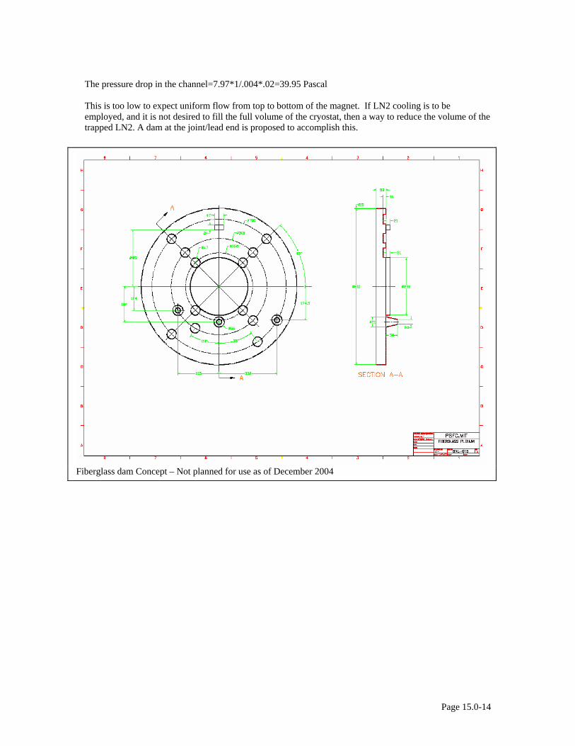
The pressure drop in the channel=7.97*1/.004*.02=39.95 Pascal This is too low to expect uniform flow from top to bottom of the magnet. If LN2 cooling is to be employed, and it is not desired to fill the full volume of the cryostat, then a way to reduce the volume of the trapped LN2. A dam at the joint/lead end is proposed to accomplish this.
Fiberglass dam Concept – Not planned for use as of December 2004
Page 15.0-14
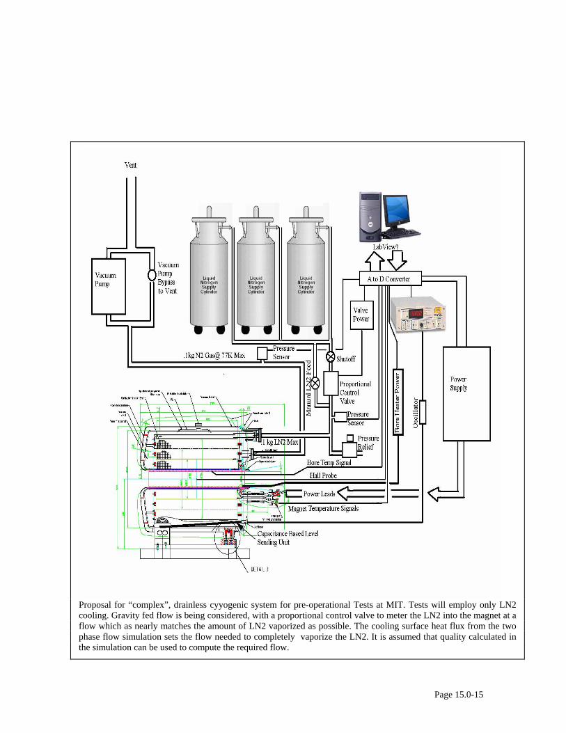
Proposal for “complex”, drainless cyyogenic system for pre-operational Tests at MIT. Tests will employ only LN2 cooling. Gravity fed flow is being considered, with a proportional control valve to meter the LN2 into the magnet at a flow which as nearly matches the amount of LN2 vaporized as possible. The cooling surface heat flux from the two phase flow simulation sets the flow needed to completely vaporize the LN2. It is assumed that quality calculated in the simulation can be used to compute the required flow.
Page 15.0-15
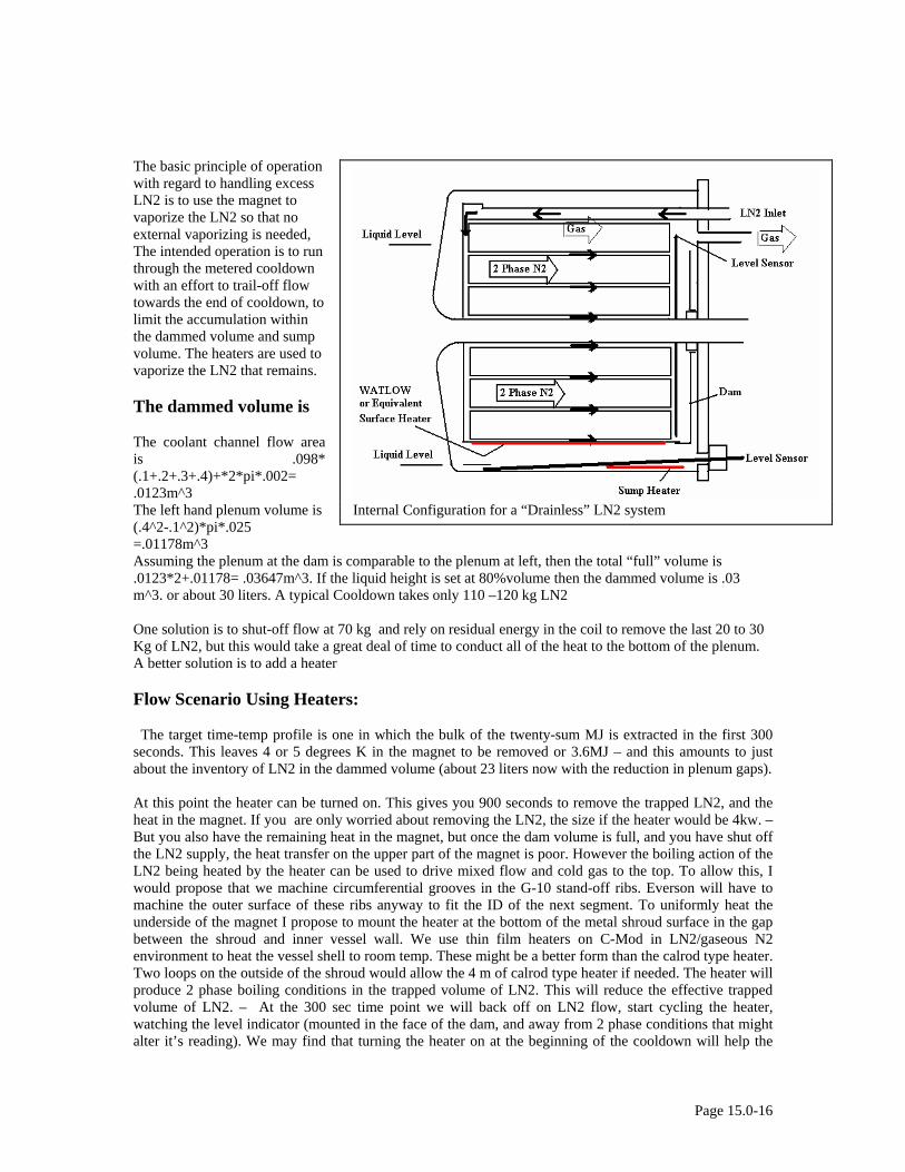
The basic principle of operation with regard to handling excess LN2 is to use the magnet to vaporize the LN2 so that no external vaporizing is needed, The intended operation is to run through the metered cooldown with an effort to trail-off flow towards the end of cooldown, to limit the accumulation within the dammed volume and sump volume. The heaters are used to vaporize the LN2 that remains. The dammed volume is The coolant channel flow area is .098* (.1+.2+.3+.4)+*2*pi*.002= .0123m^3
Internal Configuration for a “Drainless” LN2 system The left hand plenum volume is (.4^2-.1^2)*pi*.025 =.01178m^3 Assuming the plenum at the dam is comparable to the plenum at left, then the total “full” volume is .0123*2+.01178= .03647m^3. If the liquid height is set at 80%volume then the dammed volume is .03 m^3. or about 30 liters. A typical Cooldown takes only 110 –120 kg LN2 One solution is to shut-off flow at 70 kg and rely on residual energy in the coil to remove the last 20 to 30 Kg of LN2, but this would take a great deal of time to conduct all of the heat to the bottom of the plenum. A better solution is to add a heater Flow Scenario Using Heaters: The target time-temp profile is one in which the bulk of the twenty-sum MJ is extracted in the first 300 seconds. This leaves 4 or 5 degrees K in the magnet to be removed or 3.6MJ – and this amounts to just about the inventory of LN2 in the dammed volume (about 23 liters now with the reduction in plenum gaps). At this point the heater can be turned on. This gives you 900 seconds to remove the trapped LN2, and the heat in the magnet. If you are only worried about removing the LN2, the size if the heater would be 4kw. – But you also have the remaining heat in the magnet, but once the dam volume is full, and you have shut off the LN2 supply, the heat transfer on the upper part of the magnet is poor. However the boiling action of the LN2 being heated by the heater can be used to drive mixed flow and cold gas to the top. To allow this, I would propose that we machine circumferential grooves in the G-10 stand-off ribs. Everson will have to machine the outer surface of these ribs anyway to fit the ID of the next segment. To uniformly heat the underside of the magnet I propose to mount the heater at the bottom of the metal shroud surface in the gap between the shroud and inner vessel wall. We use thin film heaters on C-Mod in LN2/gaseous N2 environment to heat the vessel shell to room temp. These might be a better form than the calrod type heater. Two loops on the outside of the shroud would allow the 4 m of calrod type heater if needed. The heater will produce 2 phase boiling conditions in the trapped volume of LN2. This will reduce the effective trapped volume of LN2. – At the 300 sec time point we will back off on LN2 flow, start cycling the heater, watching the level indicator (mounted in the face of the dam, and away from 2 phase conditions that might alter it’s reading). We may find that turning the heater on at the beginning of the cooldown will help the
Page 15.0-16
flow throughout the entire process. We will monitor the magnet temperatures. Currently, the Cernox temperature sensors are placed in the top of the magnet. I would propose shifting at least 2 to the bottom to monitor the temperature near the heater to ensure that the heater is not over-heating the shroud. Towards the tail end of the cooling cycle, while we are trying to extract the last couple of degrees from the magnet, there would be a nearly empty dammed volume. The flow a in the inner segments is going to be complex, and may not be as good as for the outer segment where LN2 flow is driven by the two phase flow. We might end up with less than ideal temperatures, by about 2 or three degrees. This might be 3 or 4 degrees at the end of a pulse. this is OK from a stress standpoint. Using sub-cooling, and higher initial flows (shortening the 300 seconds) can help. This still requires some testing to find the best timing of flows and heating. Flow Equalization The simulations assume a constant pressure manifold feeding the four annular channels. Flow resistance of each channel should be comparable to produce a uniform cooldown. Specification Content: “The Seller shall perform a flow test of the assembled magnet by blowing air in the Helium outlet connection, and with the flat cover of the cryostat removed, flow velocity of each channel shall be measured with a Pitot tube. Restrictions on the channels will be applied until uniform flow is achieved. Restrictions can be in the form of g-10 strips bonded into portions of the channel opening. “ Options Using a Drain, LN2 Dump Flow and Pressure Drop Calculations There is a sheet metal plenum that surrounds the magnet for the 1, 2 or 3 segment configurations - but only on the outer segment. The down stream plenum side communicates with the vacuum pump/exhaust. After LN2 cooldown, the exhaust should be shut to minimize flow into the plenum. After the LN2 is dumped, the valve to the shuttle tank should be closed, and the exhaust/vacuum line re-opened to purge the exhaust plenum. This can be timed to provide a last bit of cooling before the next shot. If the coils are purchased with three segments installed (assuming we can afford the three) the plenum will be installed on the outside of segment three. This means that during early operation with only two segments operating, there will be coolant flow through the third segment even though it remains cold -unless it is shipped with the outer channel plugged. In which case, the cover could be removed and the plugs removed prior to full performance operation. I think wasting one channel worth of cooling is preferable over opening the cryostat, but that can be Brookhaven's choice. The coolant channel flow area is (.1+.2+.3+.4)+*2*pi*.002= .0126m^2 or about 39 square inches Assuming a 1.5 inch line to the shuttle tank, the flow area is: ~.00115m^2 or 1.77 sq. in. The wetted perimeter of the channels is (.1+.2+.3+.4)*2*2*pi=12.6 m (ignoring the 2mm ribs) The Hydraulic diameter of the channels is 4*.0126/12.6=.004 the assumed pipe wetted perimeter is .119m, and the pipe hydraulic diameter is .0381m The length of the magnet is 1m . assume the line to the shuttle tank is 2 m The ratio of the pressure drop of the pipe to the channels is: (.0126/.0015)^2*(.004/.0381)*(2/1)=25, assuming similar friction factors. So the pressure across the plenum would be much less than the pressure differential between cryostat and shuttle tank if LN2 was allowed to flow freely out the exhaust. If the exhaust line valve is closed prior to the dump to the shuttle tank, there will be almost no flow through the channels, and no pressure drop.
Page 15.0-17
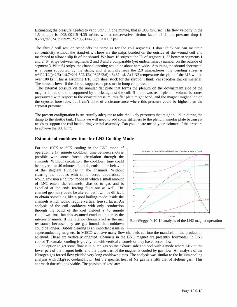
Estimating the pressure needed to vent .3m^3 in one minute, that is .005 m^3/sec. The flow velocity in the 1.5 in pipe is .005/.00115=4.35 m/sec. with a conservative friction factor of .1, the pressure drop is 857kg/m^3*4.35^2/2*.1*2/.0381=42563 Pa = 6.2 psi. The shroud will rest on stand-offs the same as for the coil segments. I don't think we can maintain concentricity without the stand-offs. These are the strips bonded on the outside of the wound coil and machined to allow a slip fit of the shroud. We have 16 strips at the ID of segment 1, 32 between segments 1 and 2, 64 strips between segments 2 and 3 and a comparable (yet undetermined) number on the outside of segment 3. With 64 strips, the channel opening would be about 4cm wide. Assuming the shroud sheetmetal is a beam supported by the strips, and it actually sees the 2.0 atmospheres, the bending stress is w*l^2/12/(t^2/6)=14.7*2*1.5^2/12/(.0625^2/6)= 8467 psi. At LN2 temperature the yield of the 316 will be over 100 ksi. This is assuming 1/16 inch sheet stock for the shroud. I think Val specifies thicker material. The stress is lower if the shroud supportsthe pressure in hoop compression. The external pressure on the annular flat plate that forms the plenum on the downstream side of the magnet is thick, and is supported by blocks against the coil. If the downstream plenum volume becomes pressurized with respect to the cryostat pressure, this flat plate might bend, and the magnet might slide on the cryostat bore tube, but I can't think of a circumstance where this pressure could be higher than the cryostat pressure. The present configuration is structurally adequate to take the likely pressures that might build up during the dump to the shuttle tank. I think we will need to add some stiffeners to the plenum annular plate because it needs to support the coil load during vertical assembly. Can you update me on your estimate of the pressure to achieve the 300 l/m?. Estimate of cooldown time for LN2 Cooling Mode For the 100K to 69K cooling in the LN2 mode of operation, a 17 minute cooldown time between shots is possible with some forced circulation through the channels. Without circulation, the cooldown time could be longer than 40 minutes. It all depends on the behavior of the stagnant fluid/gas in the channels. Without clearing the bubbles with some forced circulation, I would envision a “blurp” mode in which a small amount of LN2 enters the channels, .flashes to gas and is expelled at the ends forcing fluid out as well. The channel geometry could be altered, but it will be difficult to obtain something like a pool boiling mode inside the channels which would require vertical free surfaces. An analysis of the coil cooldown with only conduction through the build of the coil yielded a 40 minute cooldown time, but this assumed conduction across the interior channels. If the interior channels act as thermal resistance because they are gas bound, the cooldown could be longer. Bubble clearing is an important issue in superconducting magnets. In MECO we have many flow channels cut into the mandrels in the production solenoid. These are vertically oriented. Channels in the BNL magnet are presently horizontal. In LN2 cooled Tokamaks, cooling is gravity fed with vertical channels or they have forced flow.
0
10
20
30
40
50
60
70
80
90
100
0 3 6 9 12 15
Q [MJ]
V/10
R [mΩ]
I/100
T [K]
Seconds
Parameters of Pulse Coil Precooled to 69 K and Energized at 600 V to 7200 A
Bob Weggel’s 10-14 analysis of the LN2 magnet operation
One option to get some flow is to pump gas on the exhaust side and cool with a mode where LN2 at the lower part of the magnet boils, and the upper part of the magnet is cooled by gas flow. An analysis of the Nitrogen gas forced flow yielded very long cooldown times. The analysis was similar to the helium cooling analysis with .1kg/sec coolant flow, but the specific heat of N2 gas is a fifth that of Helium gas. This approach doesn’t look viable. The possible “fixes” are:
Page 15.0-18
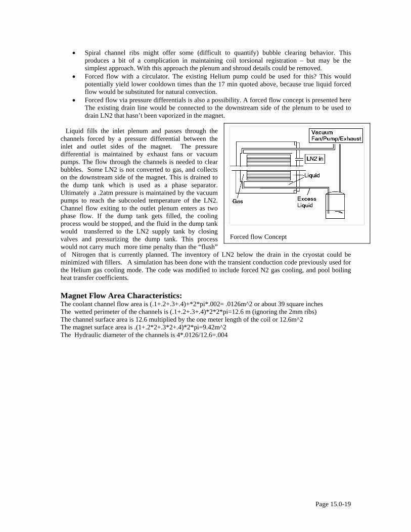
• Spiral channel ribs might offer some (difficult to quantify) bubble clearing behavior. This produces a bit of a complication in maintaining coil torsional registration – but may be the simplest approach. With this approach the plenum and shroud details could be removed.
• Forced flow with a circulator. The existing Helium pump could be used for this? This would potentially yield lower cooldown times than the 17 min quoted above, because true liquid forced flow would be substituted for natural convection.
• Forced flow via pressure differentials is also a possibility. A forced flow concept is presented here The existing drain line would be connected to the downstream side of the plenum to be used to drain LN2 that hasn’t been vaporized in the magnet.
Liquid fills the inlet plenum and passes through the channels forced by a pressure differential between the inlet and outlet sides of the magnet. The pressure differential is maintained by exhaust fans or vacuum pumps. The flow through the channels is needed to clear bubbles. Some LN2 is not converted to gas, and collects on the downstream side of the magnet. This is drained to the dump tank which is used as a phase separator. Ultimately a .2atm pressure is maintained by the vacuum pumps to reach the subcooled temperature of the LN2. Channel flow exiting to the outlet plenum enters as two phase flow. If the dump tank gets filled, the cooling process would be stopped, and the fluid in the dump tank would transferred to the LN2 supply tank by closing valves and pressurizing the dump tank. This process would not carry much more time penalty than the “flush” of Nitrogen that is currently planned. The inventory of LN2 below the drain in the cryostat could be minimized with fillers. A simulation has been done with the transient conduction code previously used for the Helium gas cooling mode. The code was modified to include forced N2 gas cooling, and pool boiling heat transfer coefficients.
Forced flow Concept
Magnet Flow Area Characteristics: The coolant channel flow area is (.1+.2+.3+.4)+*2*pi*.002= .0126m^2 or about 39 square inches The wetted perimeter of the channels is (.1+.2+.3+.4)*2*2*pi=12.6 m (ignoring the 2mm ribs) The channel surface area is 12.6 multiplied by the one meter length of the coil or 12.6m^2 The magnet surface area is .(1+.2*2+.3*2+.4)*2*pi=9.42m^2 The Hydraulic diameter of the channels is 4*.0126/12.6=.004
Page 15.0-19
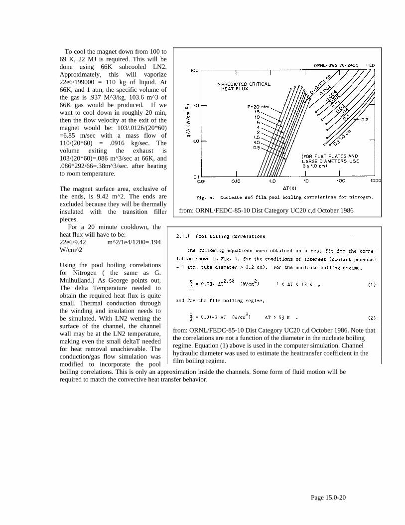
To cool the magnet down from 100 to 69 K, 22 MJ is required. This will be done using 66K subcooled LN2. Approximately, this will vaporize 22e6/199000 = 110 kg of liquid. At 66K, and 1 atm, the specific volume of the gas is .937 M^3/kg. 103.6 m^3 of 66K gas would be produced. If we want to cool down in roughly 20 min, then the flow velocity at the exit of the magnet would be: 103/.0126/(20*60) =6.85 m/sec with a mass flow of 110/(20*60) = .0916 kg/sec. The volume exiting the exhaust is 103/(20*60)=.086 m^3/sec at 66K, and .086*292/66=.38m^3/sec. after heating to room temperature. The magnet surface area, exclusive of the ends, is 9.42 m^2. The ends are excluded because they will be thermally insulated with the transition filler pieces.
from: ORNL/FEDC-85-10 Dist Category UC20 c,d October 1986
For a 20 minute cooldown, the heat flux will have to be: 22e6/9.42 m^2/1e4/1200=.194 W/cm^2 Using the pool boiling correlations for Nitrogen ( the same as G. Mulhulland.) As George points out, The delta Temperature needed to obtain the required heat flux is quite small. Thermal conduction through the winding and insulation needs to be simulated. With LN2 wetting the surface of the channel, the channel wall may be at the LN2 temperature, making even the small deltaT needed for heat removal unachievable. The conduction/gas flow simulation was modified to incorporate the pool boiling correlations. This is only an approximation inside the channels. Some form of fluid motion will be required to match the convective heat transfer behavior.
from: ORNL/FEDC-85-10 Dist Category UC20 c,d October 1986. Note that the correlations are not a function of the diameter in the nucleate boiling regime. Equation (1) above is used in the computer simulation. Channel hydraulic diameter was used to estimate the heattransfer coefficient in the film boiling regime.
Page 15.0-20
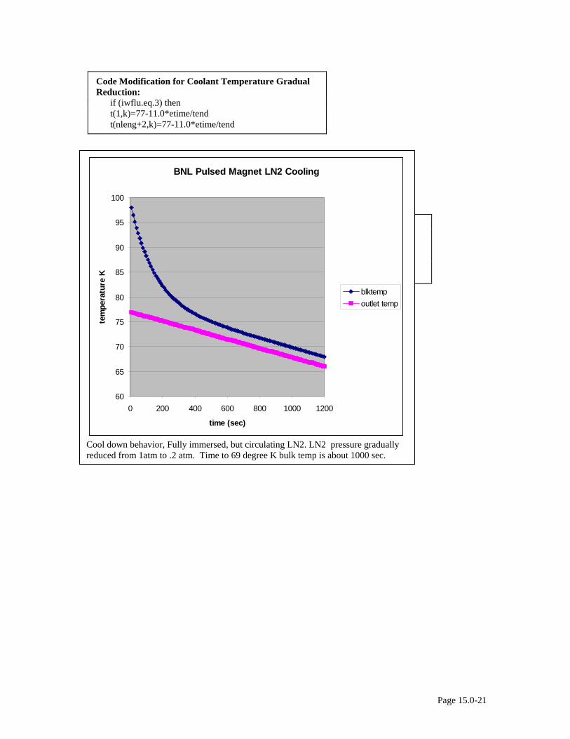
Code Modification for Coolant Temperature Gradual Reduction: if (iwflu.eq.3) then t(1,k)=77-11.0*etime/tend t(nleng+2,k)=77-11.0*etime/tend
Pool Boiling Heat Transfer Code Modifications if(iwflu.eq.3) then deltemp=t(2,k)-t(1,k) if(deltemp.ge.10.0) HC=10000 ! LN2 film boiling if(deltemp.lt.10.0) HC=340*deltemp**1.58
BNL Pulsed Magnet LN2 Cooling
60
65
70
75
80
85
90
95
100
0 200 400 600 800 1000 1200
time (sec)
tem
pera
ture
K
blktempoutlet temp
Cool down behavior, Fully immersed, but circulating LN2. LN2 pressure gradually reduced from 1atm to .2 atm. Time to 69 degree K bulk temp is about 1000 sec.
Page 15.0-21
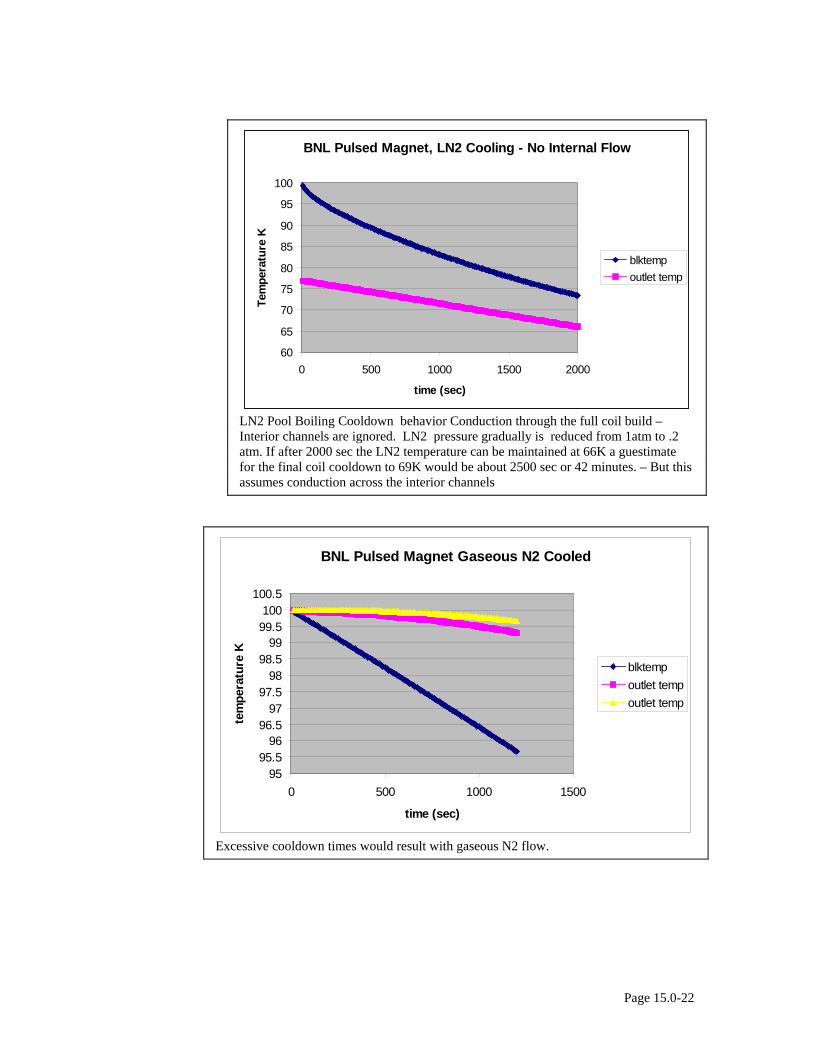
BNL Pulsed Magnet, LN2 Cooling - No Internal Flow
60
65
70
75
80
85
90
95
100
0 500 1000 1500 2000
time (sec)
Tem
pera
ture
Kblktempoutlet temp
LN2 Pool Boiling Cooldown behavior Conduction through the full coil build – Interior channels are ignored. LN2 pressure gradually is reduced from 1atm to .2 atm. If after 2000 sec the LN2 temperature can be maintained at 66K a guestimate for the final coil cooldown to 69K would be about 2500 sec or 42 minutes. – But this assumes conduction across the interior channels
BNL Pulsed Magnet Gaseous N2 Cooled
9595.5
9696.5
9797.5
9898.5
9999.5100
100.5
0 500 1000 1500
time (sec)
tem
pera
ture
K
blktempoutlet tempoutlet temp
Excessive cooldown times would result with gaseous N2 flow.
Page 15.0-22

15.6 Cryogenic System Peripherals – Vacuum Pump, Heater, Proportional Control Valve Vacuum Pump and N2 Gas (and Residual LN2) Heater:
Thermacast Heater
Vacuum Pump, and Inlet Heater ! ** Calculations **** clear let mflow=.05 !kg/sec Vacuum Pump Flow let N2gasden=1/.7996 !kg/m^3 STP ref air liquide web site let N2gasspht=1.04 !kJ/kg/degc ref air liquide web site print "Gaseous Nitrogen Density=";N2gasden;"kg/m^3" print "Gaseous Nitrogen Specific Heat=";N2gasspht;"kJ/kg/degC" let N2gasden=1.25 !kg/m^3 STP ref air liquide web site let vflow=mflow/N2gasden*60*60 ! cu meter/hr print "mass flow=";mflow;"kg/sec" print "volume flow=";vflow;"cu-m/hr" let vflow= vflow*(39.37^3/12^3)/60/60 !cu ft/sec print "volume flow = " ;vflow; "cu ft/sec" let area6=.5^2*pi/4 let area4=.33^2*pi/4 print "Exhaust Pipe Flow Velocity, 4in pipe=";vflow/area4;"feet/sec" print "Exhaust Pipe Flow Velocity, 6in pipe=";vflow/area6;"feet/sec" let heatpower=mflow*N2gasspht*(292-88) !kJ/sec or KW print"Heater Power=";heatpower;"kW"
end .05 kg/sec of LN2 is 144 cu-m/hr gas flow at RT and 1 atm Exhaust Pipe Flow Velocity, 4in pipe= 16.515614 feet/sec Exhaust Pipe Flow Velocity, 6in pipe= 7.1942017 feet/sec Heater Power= 10.608 kW Inlet Heater For a standard 12KW he provided a budgetary price of $4600. Because of the low pressure we might need a larger heat transfer area. This was estimated at $8500. It looks like this would have to be engineered a bit. The unit size is 2’ by 1’ by 4’ tall. So we can get it into our lab. Their web page is at: http://www.thermaxinc.com/indirect.htm
Thermacast™ Electric Vaporizers and Trim Heaters
Page 15.0-23

Page 15.0-24
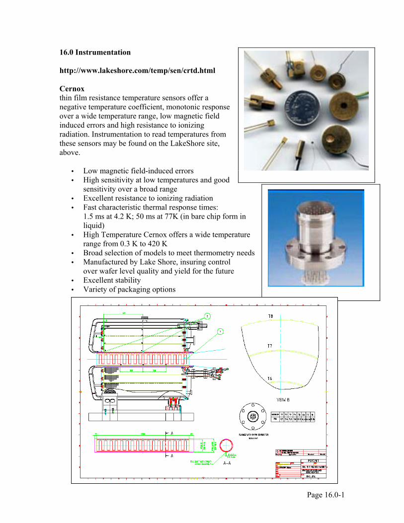
16.0 Instrumentation
http://www.lakeshore.com/temp/sen/crtd.html Cernox thin film resistance temperature sensors offer a negative temperature coefficient, monotonic response over a wide temperature range, low magnetic field induced errors and high resistance to ionizing radiation. Instrumentation to read temperatures from these sensors may be found on the LakeShore site, above.
• Low magnetic field-induced errors • High sensitivity at low temperatures and good
sensitivity over a broad range • Excellent resistance to ionizing radiation • Fast characteristic thermal response times:
1.5 ms at 4.2 K; 50 ms at 77K (in bare chip form in liquid)
• High Temperature Cernox offers a wide temperature range from 0.3 K to 420 K
• Broad selection of models to meet thermometry needs • Manufactured by Lake Shore, insuring control
over wafer level quality and yield for the future • Excellent stability • Variety of packaging options
ISI Insulator Seal
Page 16.0-1

There are 8 Cernox temperature sensors inside the cryostat, requiring 16 pins of a 19 pin penetration. Three are "spares" T9 through T11 instrument the bore liner to allow control of the thin film bore heater. The bore is to be maintained at room temperature. These do not have electrrical connections that pass through the pressure boundary. BNL-002 shows two of Item #35, the instrumentation penetration. The second pin/instrumentation flange is a spare, and is intended to accommodate other possible instrumentation BNL may want to add at a later date. The pdf of the instrumentation flange layout in BNL-014, shows 19 labeled pins matching the pin-out specs in the table.
Page 16.0-2
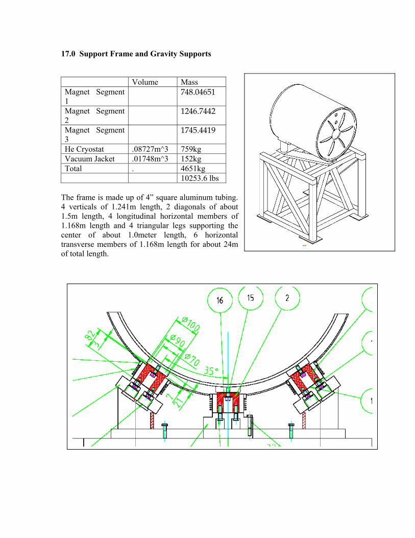
17.0 Support Frame and Gravity Supports Volume Mass Magnet Segment 1
748.04651
Magnet Segment 2
1246.7442
Magnet Segment 3
1745.4419
He Cryostat .08727m^3 759kg Vacuum Jacket .01748m^3 152kg Total . 4651kg 10253.6 lbs
The frame is made up of 4” square aluminum tubing. 4 verticals of 1.241m length, 2 diagonals of about 1.5m length, 4 longitudinal horizontal members of 1.168m length and 4 triangular legs supporting the center of about 1.0meter length, 6 horizontal transverse members of 1.168m length for about 24m of total length.
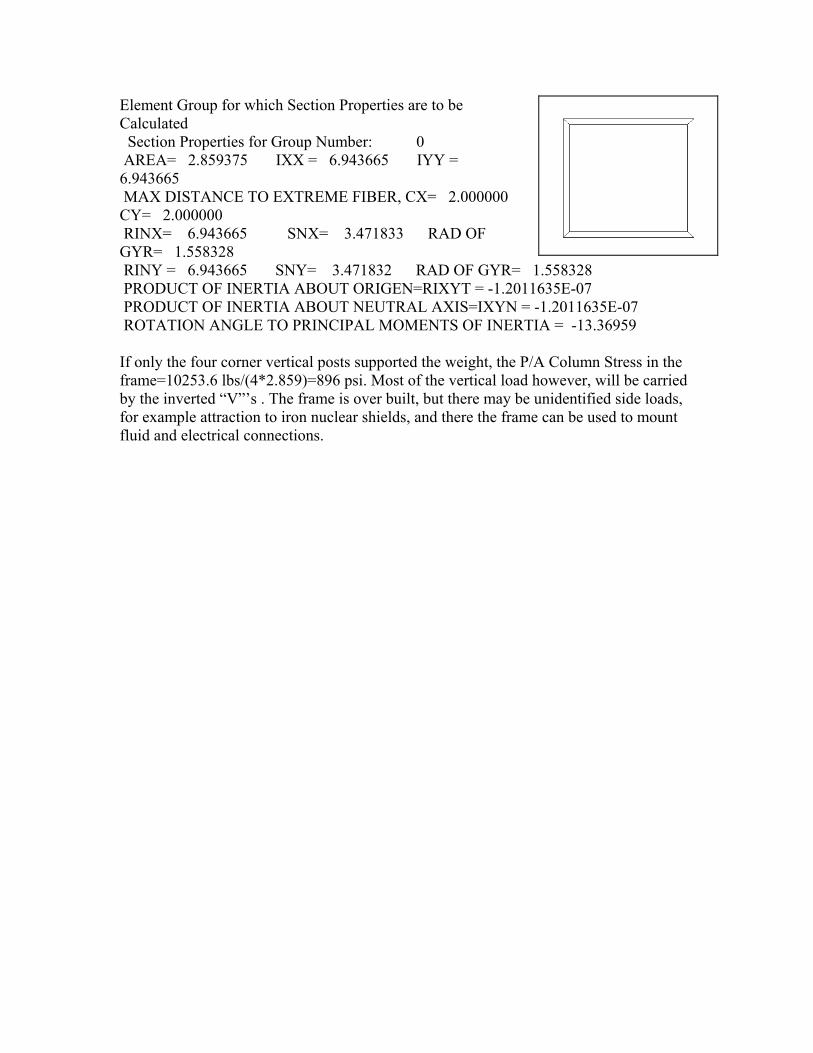
Element Group for which Section Properties are to be Calculated Section Properties for Group Number: 0 AREA= 2.859375 IXX = 6.943665 IYY = 6.943665 MAX DISTANCE TO EXTREME FIBER, CX= 2.000000 CY= 2.000000
RINX= 6.943665 SNX= 3.471833 RAD OF GYR= 1.558328 RINY = 6.943665 SNY= 3.471832 RAD OF GYR= 1.558328 PRODUCT OF INERTIA ABOUT ORIGEN=RIXYT = -1.2011635E-07 PRODUCT OF INERTIA ABOUT NEUTRAL AXIS=IXYN = -1.2011635E-07 ROTATION ANGLE TO PRINCIPAL MOMENTS OF INERTIA = -13.36959 If only the four corner vertical posts supported the weight, the P/A Column Stress in the frame=10253.6 lbs/(4*2.859)=896 psi. Most of the vertical load however, will be carried by the inverted “V”’s . The frame is over built, but there may be unidentified side loads, for example attraction to iron nuclear shields, and there the frame can be used to mount fluid and electrical connections.
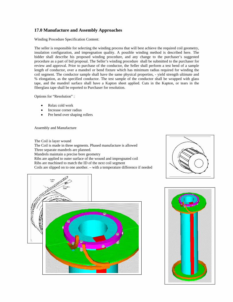
17.0 Manufacture and Assembly Approaches
Winding Procedure Specification Content: The seller is responsible for selecting the winding process that will best achieve the required coil geometry, insulation configuration, and impregnation quality. A possible winding method is described here. The bidder shall describe his proposed winding procedure, and any change to the purchaser’s suggested procedure as a part of bid proposal. The Seller’s winding procedure shall be submitted to the purchaser for review and approval. Prior to purchase of the conductor, the Seller shall perform a test bend of a sample length of conductor, over a mandrel or bend fixture which has minimum radius required for winding the coil segment. The conductor sample shall have the same physical properties, - yield strength ultimate and % elongation, as the specified conductor. The test sample of the conductor shall be wrapped with glass tape, and the mandrel surface shall have a Kapton sheet applied. Cuts in the Kapton, or tears in the fiberglass tape shall be reported to Purchaser for resolution. Options for “Resolution” :
• Relax cold work • Increase corner radius • Pre bend over shaping rollers
Assembly and Manufacture
The Coil is layer wound The Coil is made in three segments. Phased manufacture is allowed Three separate mandrels are planned. Mandrels maintain a precise bore geometry Ribs are applied to outer surface of the wound and impregnated coil Ribs are machined to match the ID of the next coil segment Coils are slipped on to one another. – with a temperature difference if needed
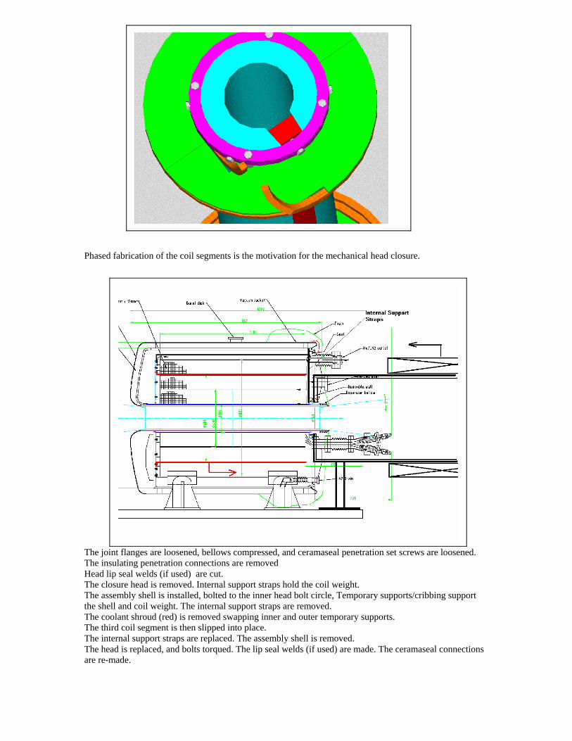
Phased fabrication of the coil segments is the motivation for the mechanical head closure.
The joint flanges are loosened, bellows compressed, and ceramaseal penetration set screws are loosened.
The insulating penetration connections are removed Head lip seal welds (if used) are cut. The closure head is removed. Internal support straps hold the coil weight. The assembly shell is installed, bolted to the inner head bolt circle, Temporary supports/cribbing support the shell and coil weight. The internal support straps are removed. The coolant shroud (red) is removed swapping inner and outer temporary supports. The third coil segment is then slipped into place. The internal support straps are replaced. The assembly shell is removed. The head is replaced, and bolts torqued. The lip seal welds (if used) are made. The ceramaseal connections are re-made.
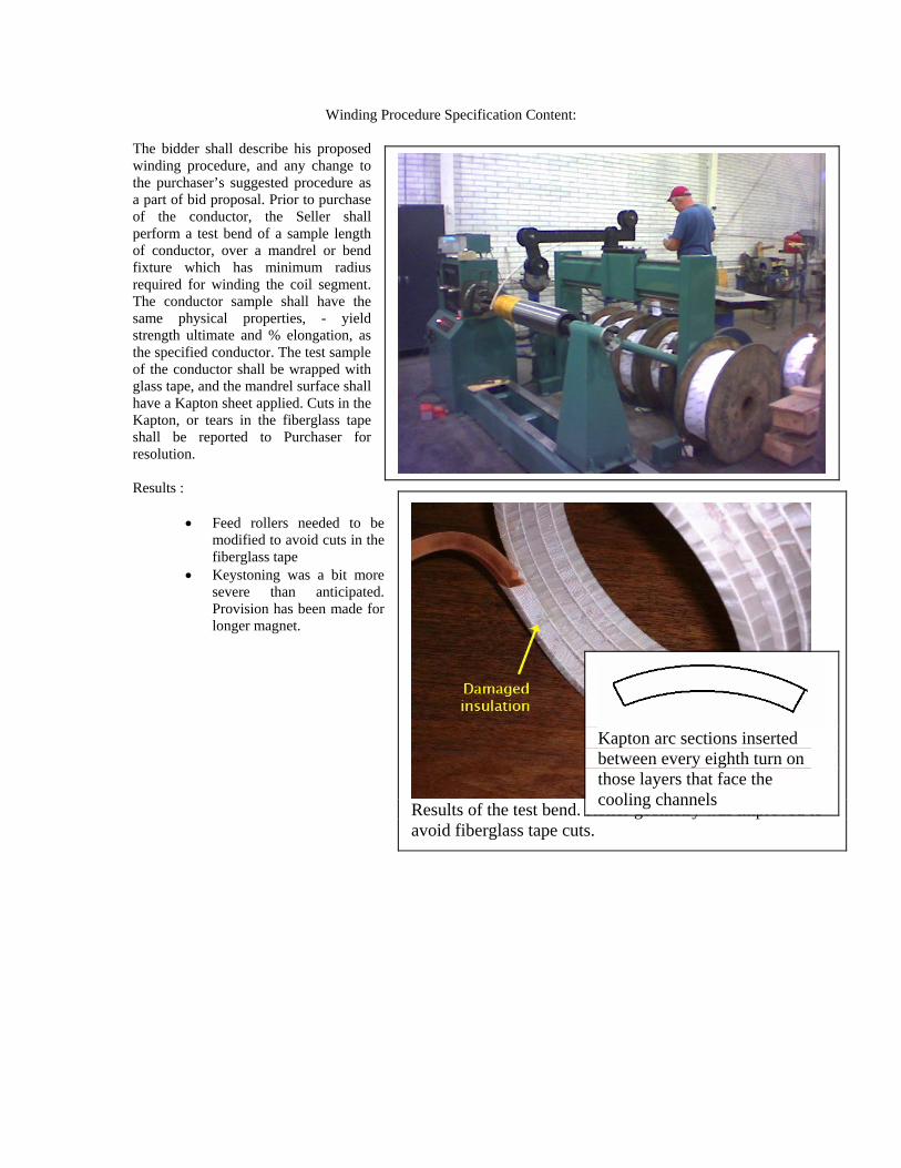
Winding Procedure Specification Content: The bidder shall describe his proposed winding procedure, and any change to the purchaser’s suggested procedure as a part of bid proposal. Prior to purchase of the conductor, the Seller shall perform a test bend of a sample length of conductor, over a mandrel or bend fixture which has minimum radius required for winding the coil segment. The conductor sample shall have the same physical properties, - yield strength ultimate and % elongation, as the specified conductor. The test sample of the conductor shall be wrapped with glass tape, and the mandrel surface shall have a Kapton sheet applied. Cuts in the Kapton, or tears in the fiberglass tape shall be reported to Purchaser for resolution. Results :
• Feed rollers needed to be modified to avoid cuts in the fiberglass tape
• Keystoning was a bit more severe than anticipated. Provision has been made for longer magnet.
Results of the test bend. R s improved to oller geometry waavoid fiberglass tape cuts.
Kapton arc sections inserted between every eighth turn on those layers that face the cooling channels
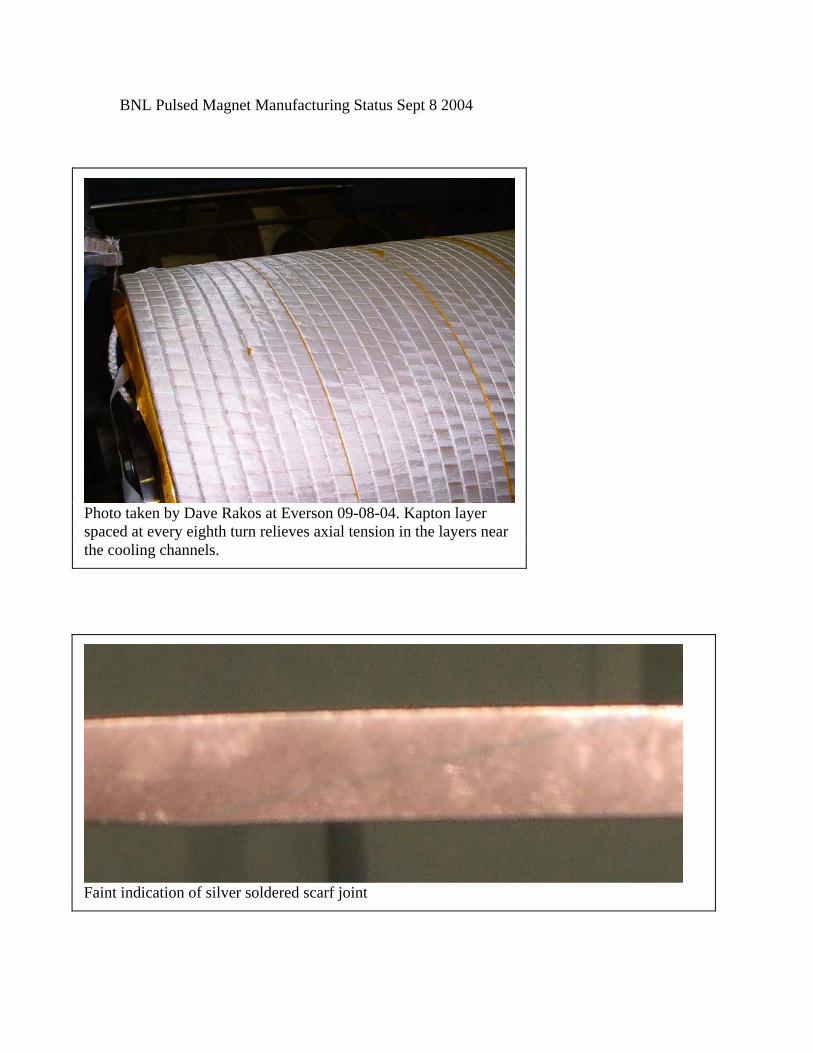
BNL Pulsed Magnet Manufacturing Status Sept 8 2004
Photo taken by Dave Rakos at Everson 09-08-04. Kapton layer spaced at every eighth turn relieves axial tension in the layers near the cooling channels.
Faint indication of silver soldered scarf joint
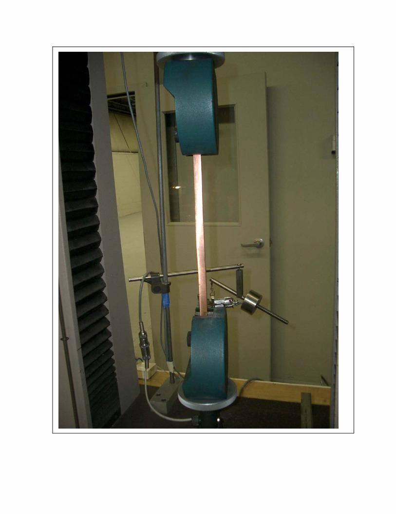
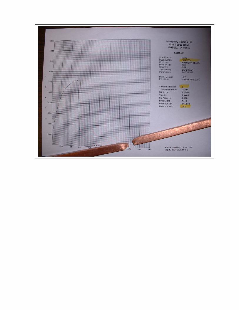

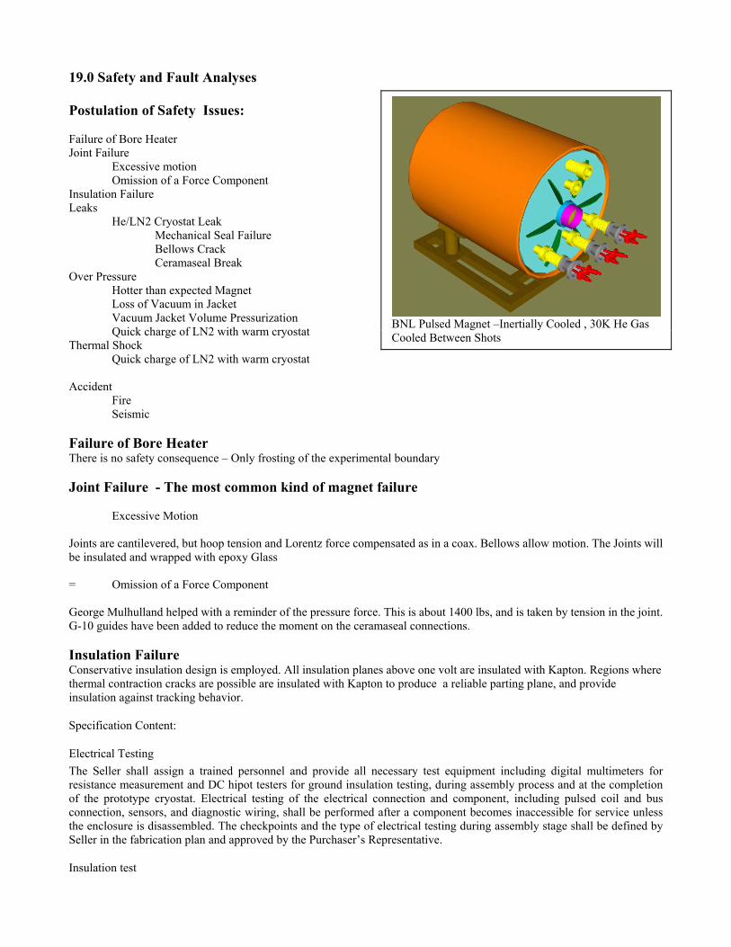
19.0 Safety and Fault Analyses
BNL Pulsed Magnet –Inertially Cooled , 30K He Gas Cooled Between Shots
Postulation of Safety Issues: Failure of Bore Heater Joint Failure Excessive motion Omission of a Force Component Insulation Failure Leaks He/LN2 Cryostat Leak Mechanical Seal Failure Bellows Crack Ceramaseal Break Over Pressure Hotter than expected Magnet Loss of Vacuum in Jacket Vacuum Jacket Volume Pressurization Quick charge of LN2 with warm cryostat Thermal Shock Quick charge of LN2 with warm cryostat Accident Fire Seismic Failure of Bore Heater There is no safety consequence – Only frosting of the experimental boundary Joint Failure - The most common kind of magnet failure Excessive Motion Joints are cantilevered, but hoop tension and Lorentz force compensated as in a coax. Bellows allow motion. The Joints will be insulated and wrapped with epoxy Glass = Omission of a Force Component George Mulhulland helped with a reminder of the pressure force. This is about 1400 lbs, and is taken by tension in the joint. G-10 guides have been added to reduce the moment on the ceramaseal connections. Insulation Failure Conservative insulation design is employed. All insulation planes above one volt are insulated with Kapton. Regions where thermal contraction cracks are possible are insulated with Kapton to produce a reliable parting plane, and provide insulation against tracking behavior.
Specification Content:
Electrical Testing The Seller shall assign a trained personnel and provide all necessary test equipment including digital multimeters for resistance measurement and DC hipot testers for ground insulation testing, during assembly process and at the completion of the prototype cryostat. Electrical testing of the electrical connection and component, including pulsed coil and bus connection, sensors, and diagnostic wiring, shall be performed after a component becomes inaccessible for service unless the enclosure is disassembled. The checkpoints and the type of electrical testing during assembly stage shall be defined by Seller in the fabrication plan and approved by the Purchaser’s Representative.
Insulation test
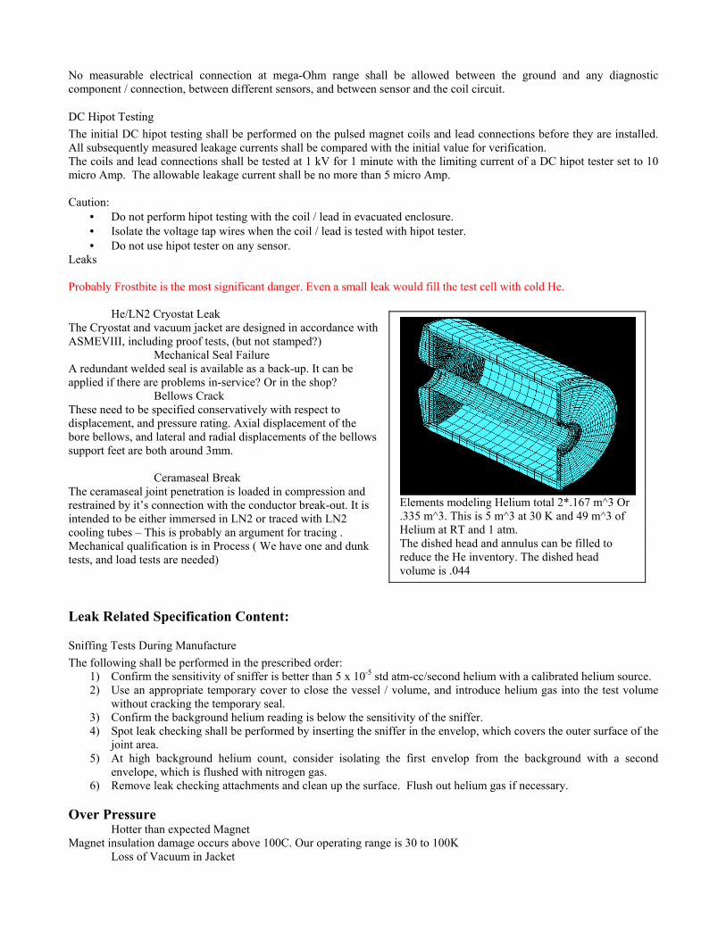
No measurable electrical connection at mega-Ohm range shall be allowed between the ground and any diagnostic component / connection, between different sensors, and between sensor and the coil circuit.
DC Hipot Testing The initial DC hipot testing shall be performed on the pulsed magnet coils and lead connections before they are installed. All subsequently measured leakage currents shall be compared with the initial value for verification. The coils and lead connections shall be tested at 1 kV for 1 minute with the limiting current of a DC hipot tester set to 10 micro Amp. The allowable leakage current shall be no more than 5 micro Amp. Caution:
• Do not perform hipot testing with the coil / lead in evacuated enclosure. • Isolate the voltage tap wires when the coil / lead is tested with hipot tester. • Do not use hipot tester on any sensor.
Leaks Probably Frostbite is the most significant danger. Even a small leak would fill the test cell with cold He. He/LN2 Cryostat Leak
Elements modeling Helium total 2*.167 m^3 Or .335 m^3. This is 5 m^3 at 30 K and 49 m^3 of Helium at RT and 1 atm. The dished head and annulus can be filled to reduce the He inventory. The dished head volume is .044
The Cryostat and vacuum jacket are designed in accordance with ASMEVIII, including proof tests, (but not stamped?) Mechanical Seal Failure A redundant welded seal is available as a back-up. It can be applied if there are problems in-service? Or in the shop? Bellows Crack These need to be specified conservatively with respect to displacement, and pressure rating. Axial displacement of the bore bellows, and lateral and radial displacements of the bellows support feet are both around 3mm. Ceramaseal Break The ceramaseal joint penetration is loaded in compression and restrained by it’s connection with the conductor break-out. It is intended to be either immersed in LN2 or traced with LN2 cooling tubes – This is probably an argument for tracing . Mechanical qualification is in Process ( We have one and dunk tests, and load tests are needed)
Leak Related Specification Content:
Sniffing Tests During Manufacture The following shall be performed in the prescribed order:
1) Confirm the sensitivity of sniffer is better than 5 x 10⁻⁵ std atm-cc/second helium with a calibrated helium source. 2) Use an appropriate temporary cover to close the vessel / volume, and introduce helium gas into the test volume
without cracking the temporary seal. 3) Confirm the background helium reading is below the sensitivity of the sniffer. 4) Spot leak checking shall be performed by inserting the sniffer in the envelop, which covers the outer surface of the
joint area. 5) At high background helium count, consider isolating the first envelop from the background with a second
envelope, which is flushed with nitrogen gas. 6) Remove leak checking attachments and clean up the surface. Flush out helium gas if necessary.
Over Pressure Hotter than expected Magnet Magnet insulation damage occurs above 100C. Our operating range is 30 to 100K Loss of Vacuum in Jacket
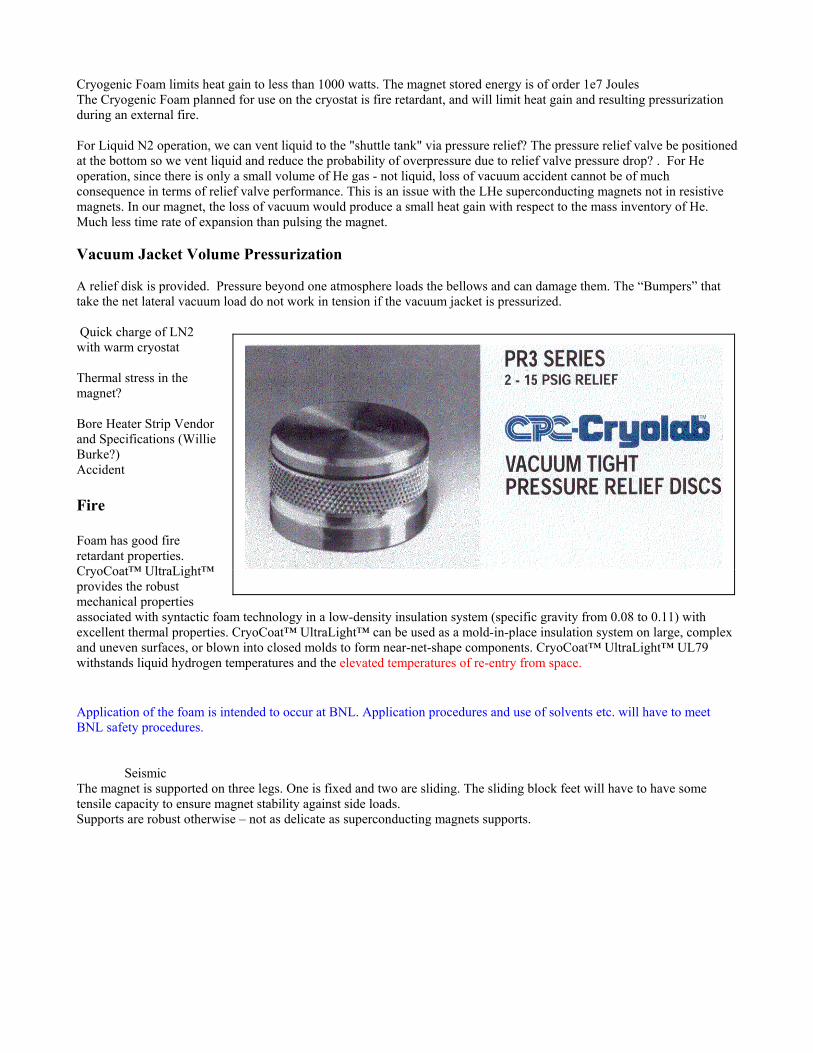
Cryogenic Foam limits heat gain to less than 1000 watts. The magnet stored energy is of order 1e7 Joules The Cryogenic Foam planned for use on the cryostat is fire retardant, and will limit heat gain and resulting pressurization during an external fire. For Liquid N2 operation, we can vent liquid to the "shuttle tank" via pressure relief? The pressure relief valve be positioned at the bottom so we vent liquid and reduce the probability of overpressure due to relief valve pressure drop? . For He operation, since there is only a small volume of He gas - not liquid, loss of vacuum accident cannot be of much consequence in terms of relief valve performance. This is an issue with the LHe superconducting magnets not in resistive magnets. In our magnet, the loss of vacuum would produce a small heat gain with respect to the mass inventory of He. Much less time rate of expansion than pulsing the magnet. Vacuum Jacket Volume Pressurization A relief disk is provided. Pressure beyond one atmosphere loads the bellows and can damage them. The “Bumpers” that take the net lateral vacuum load do not work in tension if the vacuum jacket is pressurized. Quick charge of LN2 with warm cryostat Thermal stress in the magnet? Bore Heater Strip Vendor and Specifications (Willie Burke?) Accident
Fire
Foam has good fire retardant properties. CryoCoat™ UltraLight™ provides the robust mechanical properties associated with syntactic foam technology in a low-density insulation system (specific gravity from 0.08 to 0.11) with excellent thermal properties. CryoCoat™ UltraLight™ can be used as a mold-in-place insulation system on large, complex and uneven surfaces, or blown into closed molds to form near-net-shape components. CryoCoat™ UltraLight™ UL79 withstands liquid hydrogen temperatures and the elevated temperatures of re-entry from space.
Application of the foam is intended to occur at BNL. Application procedures and use of solvents etc. will have to meet BNL safety procedures. Seismic The magnet is supported on three legs. One is fixed and two are sliding. The sliding block feet will have to have some tensile capacity to ensure magnet stability against side loads. Supports are robust otherwise – not as delicate as superconducting magnets supports.