Embed Size (px)
Citation preview

1
Submitted to Dr. AKM Abdul Malek Azad
Associate Professor, Department of EEE BRAC University
Submitted by
Marufa Ferdausi 09310014
Department of Electrical and Electronics Engineering
BRAC University, Dhaka, Bangladesh
DESIGNING SMART CHARGE
CONTROLLER FOR THE SOLAR
BATTERY CHARGING STATION (SBCS)

2
DECLARATION
I hereby declare that this thesis report has been written based only on the works and results found by me. Material of the works or research or thesis by other researchers are mentioned by their references. This thesis, neither in whole nor in part, has been previously submitted for any degree. Signature of Supervisor Signature of Author

3
ACKNOWLEDGEMENTS
I am very thankful to our thesis coordinator Dr. AKM Abdul Malek Azad, Associate Professor, Department of Electrical and Electronic Engineering, BRAC University for guiding me throughout our thesis work. Special thanks for helping by giving appropriate advice with the system devices, system designing, circuit works and other documentation. Special regards to our project engineer, Mr. Tahsin Faraaz for being with me throughout the whole thesis period with his extreme hard works and fantastic ideas.

4
ABSTRACT
Solar panels-the vital element of this SBCS makes use of exhausted energy. Compared to all other energy solar energy is abundant and free that can be used to charge batteries used for any module or electrical kits which are obvious for daily usage. The Smart Charge Controller will be designed such, so that the solar battery does not get over charged thereby ensuring no reduction of durability of the battery. This kind of system requires sensors to sense whether the battery is fully charged or not. After fully charged, detection safety can be achieved by designing a logic system in the charger, which will automatically disconnect or cut power to the battery when it is fully charged. When the solar batteries come into account, they get charged in a very short time period considering of the solar/sun/light hours per day, which is 5 hours in Bangladesh; wheras Diesel Battery Charging Stations (DBCS) take 1-2 days.
5
TABLE OF CONTENTS
Topic Page
TITLE……………………………………………………………………………….…..........1
DECLARATION………………………………………………………………………….….2
ACKNOWLEDGMENT………………………………………………….………………….3
ABSTRACT……………………………………………………………….…………………4
TABLE OF CONTENT………………………………………………….…………………..5
LIST OF FIGURES………………………………………………………………………....7
LIST OF TABLES…………………………………………………………………………...9
CHAPTER 1: INTRODUCTION
1.1 Background ………………………………………………………………11
1.2 Motivation………………………………………………………………….12
1.3 Objective …………………………………………………………………..12
1.4 Thesis Outline… …………………………………………………………13
CHAPTER 2: PROJECT OVERVIEW
2.1 PV panel …………………………………………………………………..15
2.2 Charge Controller…………………………………………………………15
2.3 Battery .................…………………………………………………………16
CHAPTER 3: SYSTEM DESCRIPTION
3.1 Solar panel…………………………………………………………….....19
3.2 Charger unit……………………………………………………………...20
3.3 Battery…………………………………………………………………..…22
CHAPTER 4: MICRO C CODING
4.1 Programming the PIC……………………………………………………25
4.2 Charge Controller Algorithm……………………………………………25
4.3 Mikro c code………………………………………………………………27
CHAPTER 5: IMPLEMENTATION IN PROTEUS
5.1 Circuit Components………………………………………………….......30
5.2 Schematic Circuit……………………………………………………...…..30
5.3 Simulation Result………………………………………………..….....….31
CHAPTER 6: DESIGN
6.1 Charge Controller Types ………….…..…………………………...…...33
6.2 Overcharge Protection………………………………………………......36
6.3 Deep Discharge Protection…………………………………………......36
6.4 Charge Controller Set Points………………………………………...…37
6.5 Charger Circuit………………………………………………………......39
6.6 PCB Implementation………………………………………………....…..40
CHAPTER 7: INTERFACING
7.1 Why Interfacing? .................................................................................42

6
7.2 How to Interface..................................................................................42
CHAPTER 8: EXPERIMENTAL RESULTS
8.1 Balance of System…………………………………………………….....44
8.2 Experiment on Different Charge Controller…………………….....….44
8.3 Laboratory Test………………………………………………………....…48
CHAPTER 9: CONCLUSION
9.1 Boundaries Of The Current Job……………………………………......50
9.2 Future Work…………………………………………………………...….51
REFERENCE
APPENDICES

7
LIST OF FIGURES
Figure Page
Figure 2.1: Charge controller and battery wiring...................................................... 16 Figure2.2: Standard Model of SBCS.........................................................................18 Figure 3.1: Battery discharge profile ……………………….…………………….….... 21 Figure 3.2: Types of PIC Microcontroller ……………………….…………………….. 23 Figure 3.3: IRFZ44N MOSFET …………………………….………….…………......... 24 Figure 4.1: Charging algorithm …………………………….………….…………......... 26 Figure 5.1: The schematic circuit ……...………………….………….…………......... 30 Figure 5.2: No charge ............................................................................................. 31 Figure 5.3: 10% pulse width ……………………....……….………….…………......... 31 Figure 5.4: 90% pulse width ……………………....……….………….…………......... 32 Figure 6.1: The diagram of charging stages of lead-acid battery ……..………….… 33 Figure 6.2: Shunt Controller ………………………..………………………..…………. 34 Figure 6.3: Series Controller ………………………………………………..……...…… 35 Figure 6.4: Charge controller set points ……………………….....…………………… 38 Figure 6.5: The charger circuit ……...……………......…….………….…………......... 40 Figure 6.6: PCB Implementation ……...……………......…….……….…………......... 41 Figure 7.1: Signal flow into the software part.............................................................43 Figure 8.1: Off load test …………………………………………………....…....………. 45 Figure 8.2: Charge controller I-V characteristic .……………………….……...……... 45 Figure 8.3: Charge controller P-V characteristics ……………………………....…….. 46 Figure 8.4: Rahimafrooz charge controller …………………………………..…...…… 46

8
Figure 8.5: Circuit of the Rahimafrooz charge controll.………………………………. 47 Figure 8.6: No charge wave shape …………………………..…………...…..........….. 48 Figure 8.7: Bulk charging wave shape ……………………....…………….........…….. 48 Figure 8.8: Float charging wave shape ……………………..……….........……….….. 49 Figure 8.9: Full charge wave shape …………....…………………………..........……. 49

9
LIST OF TABLES
Table Page Table 3.1: Battery state of charge ……………………......…………………………….17
Table 3.1: Battery I-V Characteristics ………………………………………………….20
Table 8.1: Charge Controller Off Load Test ………………………………………..... 45
10
CHAPTER 1
INTRODUCTION
Solar Energy, radiation produced by nuclear fusion reactions deep in the Sun‟s core
The Sun provides almost all the heat and light Earth receives and therefore sustains
every living being. Bangladesh being a country being concerned about environmental
problems, sustainable energy sources is becoming more and more popular here. Solar
energy can be converted to electricity directly by SHS systems. Flow of converted
electricity from PV is determined by charge controller. An efficient charge controller can
be used to do the battery charging and discharging process faster and better. The
existing electric grids are not capable of supplying the electric need. Thus the Solar
Battery Charging Station (SBCS) is a new project that has emerged to the rural
Bangladesh as well as in urban areas to change the scenario. Now, the required
manpower and economic problem is less.
The smart charge controller is designed with a view to decrease the battery charging
time, making it capable of charging more than one battery at a time and getting the
desired current from the PV panel.
Central Solar Battery Charging Station (CSBCS) provides power to trickle charging of
batteries from stand-alone solar panels. People bring own their batteries or rent from
the station for recharging up to a specific voltage level-which is monitored by the newly
developed software dedicated for this project. CSBCS was initially conceived worldwide
to bring the price per household of electrification within the capacity to pay of the rural
poor, and to foster the establishment of community businesses supplying the modest
electricity demands of end users far from the grid in an entrepreneur-based
electrification model.
Considering the raising needs for electricity, Bangladesh strains solar energy as backup
for electricity generation to enhance the shortage of power which the national grid is
unable to provide. Moreover our poverty corrupted rural area faces the toughest
criterions for crisis of electricity. Therefore, our aim is to make solar energy popular as
one of the best renewable energy sources among our people by implementing Central
Solar Battery Charging Station with a view to provide supplementary electricity.
Resultantly, more and more people are now using solar energy as their main source of
electricity. Using compound solar cells, solar panels manage to trap huge amounts of
energy every single day. When the solar batteries come into account, they get charged
in a very short time period considering of the solar/sun/light hours per day, which is 5
hours in Bangladesh; whereas Diesel Battery Charging Stations (DBCS) take 1-2

11
days.[1]The electricity is instantaneously converted and then stored in the charging
station which is consumed by the batteries. If the panels produce power which is not
required instantly, customers can at rest get hold of that energy in the outlook,
whenever they oblige it. People whoever looking for savings and the future of the planet
should indeed look into solar energy.
1.1 BACKGROUND
Crisis of electricity is a major problem in the present era. This problem is even more
critical for a densely populated poverty corrupted developing third world country like
ours. Many of our people live here without the basic facility of electricity. In some area
outside the city side, there is general electricity service called „PALLI BIDYUT‟ which
can supply a very limited amount of electricity in those area that is unable cover up the
basic demand of people from those area. Day by day crisis of electricity is increasing
whereas no other solution is left for us without using the solar power or wind turbine to
generate electricity. Again, not only we face electricity crisis but also day by the cost of
gas and other natural resources like fuel, diesel , petroleum etc are rising up that is
going beyond the availably of general people. Thereby such a system that can not only
reduce the electricity crisis but also the crisis of petroleum or other natural resources for
driving vehicles is desirable.
We have designed a whole Central Solar Battery Charging Station (CSBCS) along with
the successful implementation of hardware and software to represent all activities not
only visually but also can be monitored and controlled from remote region.
Implementation of SBCS for also includes designing of a smart charge controller with a
view to decrease the battery charging time, making it capable of charging more than
one battery at a time and getting the desired current from the load.
1.2 MOTIVATION
Ours is a tropical country where the amount of sunlight is mostly available to meet up
the demand of producing electricity. This type of project is not new but for our country of
this can be implemented successfully for commercial purpose, it can bring a
revolutionary change in the lifestyle and the economical prospectus that also can
increase the GDP of Bangladesh. As ours is a massively power-deficient country with
peak power shortages of around 25%. More than 60% of its people do not have access
to the power grid. The country only produces 3500-4200 MW of electricity against a
daily demand for 4000-5200 MW on average, according to official estimates. Solar
energy is an ideal solution as it can provide griddles power and is totally clean in terms

12
of pollution and health hazards. Since it saves money on constructing electricity
transmission lines, it‟s economical as well. The solar panel providers in Bangladesh are
now expecting the price of batteries and accessories to drastically reduce. Moreover,
after the current budget of 2012 the price for per unit electricity will be amplified more. It
is flattering tougher for ordinary mass to cope up with the mounting price of per unit
electricity of PDB. So the best alternative is to development of SBCS in our country
effectively.
Considering all these we are motivated to do this project as it will help our people in
several ways. Our people are not too much efficient in monitoring. We can make use of
software available too. Through monitoring we can control our system from remote
areas thereby efficiently that paves us to do the development of software
implementation thereby.
1.3 OBJECTIVE
1) We can charge the batteries used in solar home system or in IPS in our station
and our well developed monitoring software will save the batteries from further
destructions caused by the system.
2) Our charging station can be used to charge any battery including Rickshaw
battery or batteries used in Solar Home System either in rental or in monthly
payment basis.
3) Electric lanterns used in village area can be charged as well.
4) First objective of this thesis is to identify reasons for the failures of existing
charge control algorithms that utilize existing technologies.
5) The next goal of the thesis is to create new charge control algorithms that will
overcome the issue of false detection while protecting the battery from repetitive
overcharges. We present a new voltage based charge control algorithm.
6) Ways to increase the charging speed are critical in this application as well as in
most of other applications since portable solar panel generally have low power
production per square meter. So, this research also develops ways to optimize
solar panels‟ output power while charging the batteries.
7) Our software is able to eliminate costs.
13
8) Followed by some other countries we can also replace kerosene station with
Solar Battery Charging Station too with further modification.
1.4 THESIS OUTLINE
This Photovoltaic Charge Controller final thesis is arranged into following chapter:
Chapter 2: Literature reviews of this project based on journals and other references.
Chapter 3: Methodologies for the development of Photovoltaic Charge Controller.
Details on the progress of the project are explained in this chapter.
Chapter 4: The algorithm of the Charge Controller circuit and the code implemented in
the microcontroller.
Chapter 5: Simulation and the whole system result.
Chapter 6: Design of the hardware and software of the prototype poject.
Chapter 7: The interfacing between the two groups.
Chapter 8: Results obtained and the limitation of the project. Discussions are
concentrating on the result and performance of Photovoltaic Charge Controller.
Chapter 9: Concludes overall about the project. Obstacle faces and future
recommendation are also discussed in this chapter.

14
CHAPTER 2
PROJECT OVERVIEW
2.1 PV PANEL
In a photovoltaic cell, light excites electrons to move from one layer to another through
semi-conductive silicon materials. This produces an electric current.
Solar cells called photovoltaics made from thin slices of crystalline silicon, gallium
arsenide, or other semiconductor materials convert solar radiation directly into
electricity. Cells with conversion efficiencies greater than 30 percent are now available.
By connecting large numbers of these cells into modules, the cost of photovoltaic
electricity has been reduced to 20 to 30 cents per kilowatt-hour. Americans currently
pay 6 to 7 cents per kilowatt-hour for conventionally generated electricity.
The simplest solar cells provide small amounts of power for watches and calculators. More complex systems can provide electricity to houses and electric grids. Usually though, solar cells provide low power to remote, unattended devices such as buoys, weather and communication satellites, and equipment aboard spacecraft.
2.2 CHARGE CONTROLLER
A charge controller, charge regulator or battery regulator limits the rate at which electric
current is added to or drawn from electric batteries. It prevents overcharging and may
prevent against overvoltage, which can reduce battery performance or lifespan, and
may pose a safety risk. It may also prevent completely draining ("deep discharging") a
battery, or perform controlled discharges, depending on the battery technology, to
protect battery life. The terms "charge controller" or "charge regulator" may refer to
either a stand-alone device, or to control circuitry integrated within a battery pack,
battery-powered device, or battery recharger.
Charge controllers are sold to consumers as separate devices, often in conjunction with
solar or wind power generators, for uses such as RV, boat, and off-the-grid home
battery storage systems. In solar applications, charge controllers may also be called
solar regulators.
A series charge controller or series regulator disables further current flow into batteries
when they are full. A shunt charge controller or shunt regulator diverts excess electricity
to an auxiliary or "shunt" load, such as an electric water heater, when batteries are full.
15
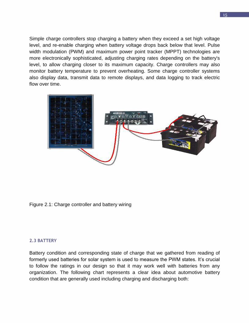
Simple charge controllers stop charging a battery when they exceed a set high voltage
level, and re-enable charging when battery voltage drops back below that level. Pulse
width modulation (PWM) and maximum power point tracker (MPPT) technologies are
more electronically sophisticated, adjusting charging rates depending on the battery's
level, to allow charging closer to its maximum capacity. Charge controllers may also
monitor battery temperature to prevent overheating. Some charge controller systems
also display data, transmit data to remote displays, and data logging to track electric
flow over time.
Figure 2.1: Charge controller and battery wiring
2.3 BATTERY
Battery condition and corresponding state of charge that we gathered from reading of
formerly used batteries for solar system is used to measure the PWM states. It‟s crucial
to follow the ratings in our design so that it may work well with batteries from any
organization. The following chart represents a clear idea about automotive battery
condition that are generally used including charging and discharging both:

16
Table2.1:Battery State of charge
STATE OF CHARGE 12 V BATTERY
20% 11.58
30% 11.75
40% 11.9
50% 12.06
60% 12.20
70% 12.32
80% 12.42
90% 12.5
100% 12.7

17
Figure2.2: Standard Model of SBCS
18
CHAPTER 3
SYSTEM DESCRIPTION
Solar Home System (SHS) generally have a common design and consists of the following components: 1. A PV Generator composed of one or more PV modules, which are interconnected to
form a DC power-producing unit. 2. A mechanical support structure for the PV generator. 3. A 12V lead acid battery. 4. A charge controller to prevent deepdischarges and overcharges of the battery 5. Loads (LED lamps) 6. Wire connections (Cable, switches and connection box.) Our whole project consists of two groups. 1. Hardware Implementation 2. Software Implementation My project is on the design and implementation of the solar charge controller. For the Solar Battery Charging Station (SBCS), the proposed CARG project has the overall implementation and monitoring system for the Solar Home System (SHS). Each component of the system must fulfill the quality and requirements. Size, voltage thresholds of the charge contoller, the quality of installation etc directly effects the lifetime of batteries and lamps.
3.1 Solar Panel
The use of the Sun as an alternative means to provide electrical energy has always
been around us. Solar Power generation has emerged as one of the most rapidly
growing renewable sources of electricity. Photovoltaic is a most elegant energy source.
Light shines on a crystal and produces electricity. It is as simple as that. There are no
moving parts. The fuel source (sunlight) is free, abundant and widely distributed,
available to every country and person in the world. At over 165,000 TW the solar
resource dwarfs the world‟s current power usage of 16 TW or even our projected future
usage of 60 TW. Doing serious battery charging with solar energy isn't that difficult.
Actually, the most critical component aside from the solar panel itself - is a solar charge
controller, which is available from many manufacturers. This device protects the battery
from being overcharged, which can reduce its life. With a charge controller in hand,
setting up a photovoltaic battery charging system is really a simple wiring procedure.

19
3.2 Battery
Solar batteries produce electricity by a photoelectric conversion process. The source of
electricity is a photosensitive semiconducting substance such as a silicon crystal to
which impurities have been added. When the crystal is struck by light, electrons are
dislodged from the surface of the crystal and migrate toward the opposite surface.
There they are collected as a current of electricity. Solar batteries have very long
lifetimes and are used chiefly in spacecraft as a source of electricity to operate the
equipment aboard.
The battery was rechargeable and of lead-acid systems. It should not be overcharged.
Otherwise, the battery is completely sealed, maintenance-free and leak proof. It was
rated as 12v and 80Ah. It should not be discharged below 80%.
On Load Off Load
T V1 V2
11.3 12.55 12.55
11.45 12.19 12.55
12.15 12.17 12.48
12.45 12.16 12.46
13.15 12.14 12.44
13.45 12.11 12.41
14.15 12.09 12.39
14.45 12.06 12.38
15.15 12.03 12.35
15.45 12.02 12.28
16.15 12.01 12.29
16.45 11.96 12.28
17.15 11.93 12.25
17.45 11.9 12.22
18.15 11.87 12.17
18.45 11.84 12.18
19.15 11.79 12.15
19.45 11.76 12.11
20.15 11.71 12.07
20.45 11.67 12.04
21 11.66 12.04
Table3.1: Battery I-V Characteristics
20
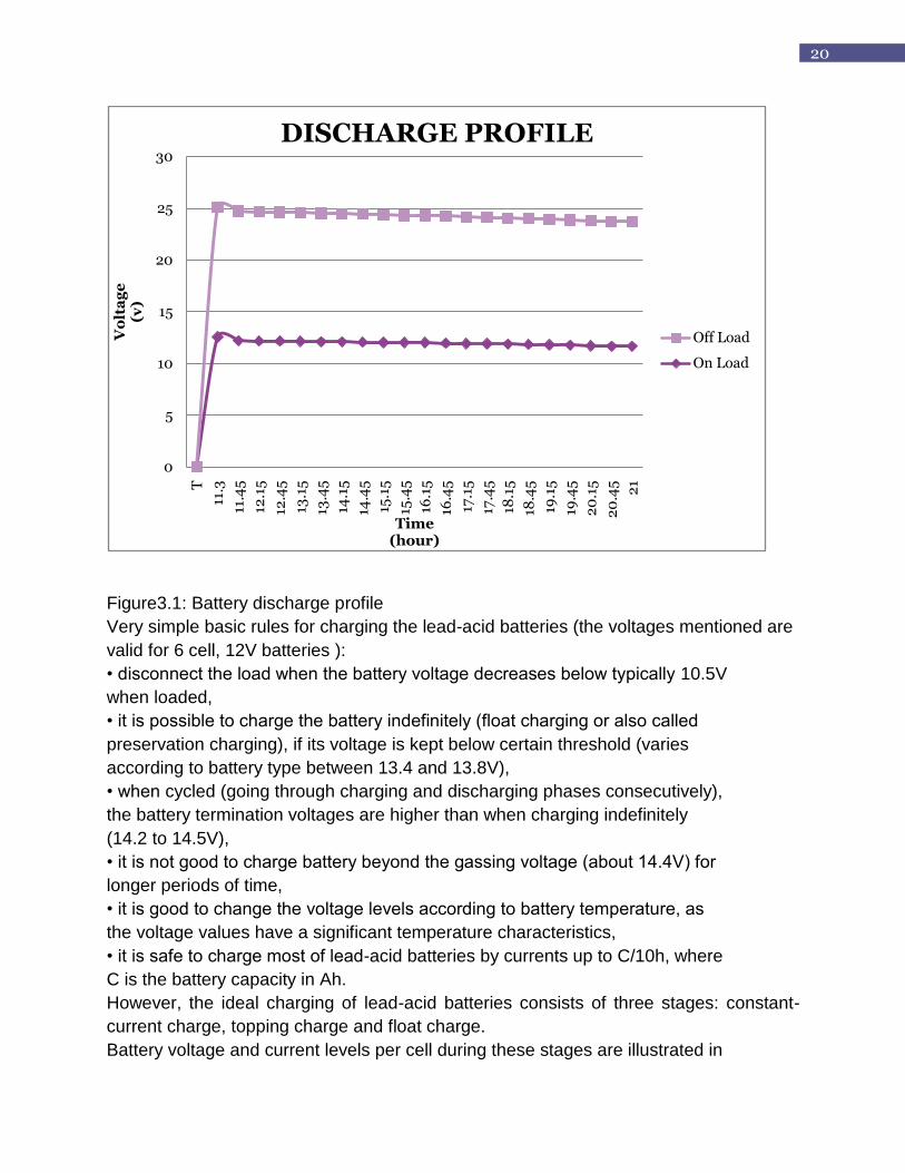
Figure3.1: Battery discharge profile
Very simple basic rules for charging the lead-acid batteries (the voltages mentioned are
valid for 6 cell, 12V batteries ):
• disconnect the load when the battery voltage decreases below typically 10.5V
when loaded,
• it is possible to charge the battery indefinitely (float charging or also called
preservation charging), if its voltage is kept below certain threshold (varies
according to battery type between 13.4 and 13.8V),
• when cycled (going through charging and discharging phases consecutively),
the battery termination voltages are higher than when charging indefinitely
(14.2 to 14.5V),
• it is not good to charge battery beyond the gassing voltage (about 14.4V) for
longer periods of time,
• it is good to change the voltage levels according to battery temperature, as
the voltage values have a significant temperature characteristics,
• it is safe to charge most of lead-acid batteries by currents up to C/10h, where
C is the battery capacity in Ah.
However, the ideal charging of lead-acid batteries consists of three stages: constant-
current charge, topping charge and float charge.
Battery voltage and current levels per cell during these stages are illustrated in
0
5
10
15
20
25
30
T
11.3
11.4
5
12.1
5
12.4
5
13.1
5
13.4
5
14.1
5
14.4
5
15.1
5
15.4
5
16.1
5
16.4
5
17.1
5
17.4
5
18.1
5
18.4
5
19.1
5
19.4
5
20
.15
20
.45 21
Vo
lta
ge
(v)
Time(hour)
DISCHARGE PROFILE
Off Load
On Load

21
Figure3.1.
Most of the energy is transferred to the battery during the first stage. The second
stage overcharges the battery a little while the current decreases. This is important
to recharge battery to 100% of its previous capacity. The losses due to self-discharge
are compensated during the last stage.
3.3 Charger Unit
3.3.1 Charge Controller
The primary function of a charge controller in a Solar Home System (SHS) is to maintain the battery at highest possible state of charge, when PV module charges the battery the charge controller protects the battery from overcharge and disconnects the load to prevent deep discharge. Ideally, charge controller directly controls the state of charge of the battery. Without charge control, the current from the module will flow into a battery proportional
to the irradiance, whether the battery needs to be charging or not. If the battery is fully
charged, unregulated charging will cause the battery voltage to reach exceedingly high
levels, causing severe gassing, electrolyte loss, internal heating and accelerated grid
corrosion. Actually charge controller maintains the health and extends the lifetime of the
battery.
3.3.2 Pulse Width Modulation (PWM)
Pulse Width Modulation (PWM) controls adjusts the duty ratio of the switches as the
input changes to produce a constant output voltage. The DC voltage is converted to a
square-wave signal, alternating between fully on and zero. By controlling analog circuits
digitally, system costs and power consumption can be drastically reduced. In nowadays
implementation, many microcontrollers already include on-chip PWM controllers,
making implementation easy. Concisely, PWM is a way of digitally encoding analog
signal levels. PWM control can be used in two ways: voltage-mode and current-mode.
In voltage mode, control the output voltage increases and decreases as the duty ratio
increases and decreases. The output voltage is sensed and used for feedback. If it has
two-stage regulation, it will first hold the voltage to a safe maximum for the battery to
reach full charge. Then it will drop the voltage lower to sustain a "finish" or "trickle"
charge. Two-stage regulating is important for a system that may experience many days
or weeks of excess energy (or little use of energy). It maintains a full charge but
minimizes water loss and stress. The voltages at which the controller changes the
charge rate are called set points. When determining the ideal set points, there is some
compromise between charging quickly before the sun goes down, and mildly
overcharging the battery. The determination of set points depends on the anticipated

22
pattern of use, the type of battery, and to some extent, the experience and philosophy of
the system designer or operator.
Determine the duty cycle, D to obtain required output voltage. D = Vo/Vd Where: D = Duty cycle
Vo = Voltage output Vd= Voltage input D = 12V/17.4V D = 0.7 %D = 70%
3.3.3 PIC 16F876A Microcontroller
The semiconductor division of General Instruments Inc originally developed the PIC
(Programmable Interface Controller) line of microcontrollers. The first PIC‟s were a
major improvement over existing microcontroller because they were a programmable,
high output current, input/output controller built around a RISC (Reduced Instruction Set
Code) architecture. The first PICs ran efficiently at one instruction per internal clock
cycle, and the clock cycle was derived from the oscillator divided by 4. Early PICs could
run with a high oscillator frequency of 20 MHz. This made them relatively fast for an 8-
bit microcontroller, but their main feature was 20 mA of source and sink current
capability on each I/O (Input/Output) pin. Typical micros of the time were advertising
high I/O currents of only 1-milliampere (mA) source and 1.6 mA sink.
Figure3.2: Types of PIC Microcontroller

23
3.3.4 Mosfet
As previously mentioned the switch would be a MOSFET (Metal Oxide Semiconductor
Field Effect Transistor). MOSFETS are by far the most popular transistors used for
switching in circuits today, along with BJTs (Bipolar Junction Transistors). The main
difference between MOSFETS and BJTs is that the former are voltage controlled (little
or no current is used) and the later are current controlled (voltages are there to control
currents). Therefore, MOSFETs require less power to drive them, so they are preferred
choice.
MOSFETs are either N‐channel, made mostly of N‐type semiconductor material, or P-
channel where they are made mostly of P‐type semiconductor material. They operate in
two modes – enhancement mode and depletion mode.
The circuit symbols for these are in figure.
Figure3.3: IRFZ44N MOSFET
MOSFET has high switching speeds, high input impedence and is ideal for switching
converters. The voltage in is applied at the gate (1), the battery ground is at the drain (2)
and the panel ground is at the source (3).

24
CHAPTER 4
MICRO C CODING
4.1 Programming the PIC
These PIC microcontrollers can be programmed in high-level languages or in
their native machine language (Assembly). In this thesis the C language was
chosen, using the software MICRO C. The advantages of C language consist of
better control and greater efficiency. Another reason for using C language is that the
interface with the programmer is quite simple and easy to understand.
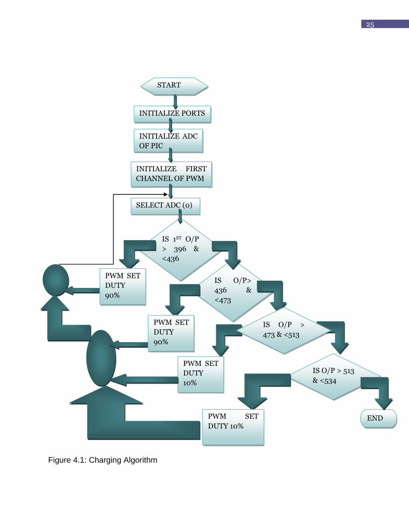
4.2 Charge Controller Algorithm
The charge controller algorithm is shown in flow chart below:
25
Figure 4.1: Charging Algorithm
START
INITIALIZE PORTS
INITIALIZE ADC
OF PIC
INITIALIZE FIRST
CHANNEL OF PWM
SELECT ADC (0)
IS 1ST O/P
> 396 &
<436
IS O/P>
436 &
<473
IS O/P > 513
& <534
END
PWM SET
DUTY
90%
PWM SET
DUTY
90%
PWM SET
DUTY
10%
IS O/P >
473 & <513
PWM SET
DUTY 10%

26
4.3 Mikro c code
The PIC 16F876A microcontroller can be programmed using PIC writer software. The
following code was written and implemented in the microcontroller:
unsigned int v1;
void main() {
TRISA=0xFF;
TRISB=0X00;
PORTB=0X00;
ADCON0=0x00;//0b00010101;
ADCON1=0b00000000;
pwm1_init(40000);
ADC_Init();
while(1)
{
pwm1_start();
delay_us(50);
v1=ADC_read(0);
if(v1<=396){ // DISCONNECTED(if battery is DEAD)
pwm1_set_duty(0);
}
else if(v1>396 && v1<=436){ // v>=396: if the battery already has charge, but less
than 50%(for normal bettery) or 30%(for solar battery) of its capacity.
pwm1_set_duty(230);
}
else if(v1>436 && v1<=473){ // BULK CHARGE
pwm1_set_duty(230);
}
if(v1>473 && v1<=513){ // ABSORPTION CHARGE
pwm1_set_duty(30);
}
else if(v1>513 && v1<534){ // FLOAT CHARGE
pwm1_set_duty(30);

27
}
else if(v1>=534){ // DISCONNECTED(if battery is fully charged or DEAD)
pwm1_set_duty(0);
}
}
}

28
CHAPTER 5
IMPLEMENTATION IN PROTEUS
ISIS provides the development environment for PROTEUS VSM, our revolutionary interactive system level simulator. This product combines mixed mode circuit simulation, microprocessor models and interactive component models to allow the simulation of complete micro-controller based designs.
ISIS provides the means to enter the design in the first place, the architecture for real time interactive simulation and a system for managing the source and object code associated with each project. In addition, a number of graph objects can be placed on the schematic to enable conventional time, frequency and swept variable simulation to be performed.
Major features of PROTEUS VSM include:
True Mixed Mode simulation based on Berkeley SPICE3F5 with extensions for digital simulation and true mixed mode operation.
Support for both interactive and graph based simulation. CPU Models available for popular microcontrollers such as the PIC and 8051
series. Interactive peripheral models include LED and LCD displays, a universal matrix
keypad, an RS232 terminal and a whole library of switches, pots, lamps, LEDs etc.
Virtual Instruments include voltmeters, ammeters, a dual beam oscilloscope and a 24 channel logic analyser.
On-screen graphing - the graphs are placed directly on the schematic just like any other object. Graphs can be maximised to a full screen mode for cursor based measurement and so forth.
Graph Based Analysis types include transient, frequency, noise, distortion, AC and DC sweeps and fourier transform. An Audio graph allows playback of simulated waveforms.
Direct support for analogue component models in SPICE format. Open architecture for „plug in‟ component models coded in C++ or other
languages. These can be electrical, graphical or a combination of the two. Digital simulator includes a BASIC-like programming language for modelling and
test vector generation. A design created for simulation can also be used to generate a netlist for creating
a PCB - there is no need to enter the design a second time.
Full details of all these features and much more are provided in the PROTEUS VSM manual.
29
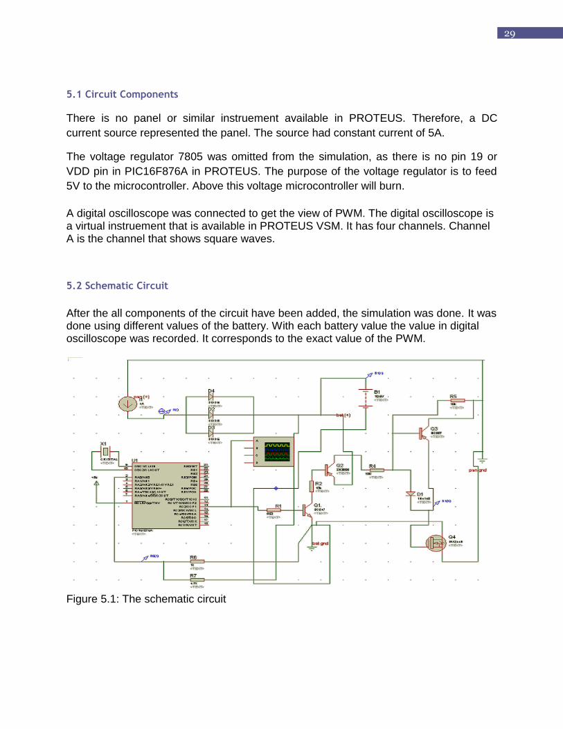
5.1 Circuit Components
There is no panel or similar instruement available in PROTEUS. Therefore, a DC
current source represented the panel. The source had constant current of 5A.
The voltage regulator 7805 was omitted from the simulation, as there is no pin 19 or
VDD pin in PIC16F876A in PROTEUS. The purpose of the voltage regulator is to feed
5V to the microcontroller. Above this voltage microcontroller will burn.
A digital oscilloscope was connected to get the view of PWM. The digital oscilloscope is a virtual instruement that is available in PROTEUS VSM. It has four channels. Channel A is the channel that shows square waves.
5.2 Schematic Circuit
After the all components of the circuit have been added, the simulation was done. It was done using different values of the battery. With each battery value the value in digital oscilloscope was recorded. It corresponds to the exact value of the PWM.
Figure 5.1: The schematic circuit
30
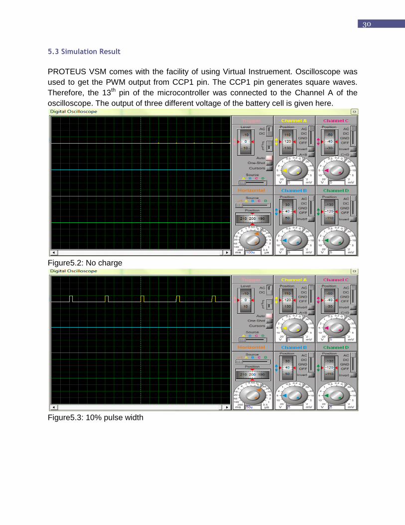
5.3 Simulation Result
PROTEUS VSM comes with the facility of using Virtual Instruement. Oscilloscope was
used to get the PWM output from CCP1 pin. The CCP1 pin generates square waves.
Therefore, the 13th pin of the microcontroller was connected to the Channel A of the
oscilloscope. The output of three different voltage of the battery cell is given here.
Figure5.2: No charge
Figure5.3: 10% pulse width

31
Figure 5.4: 90% pulse width
32
CHAPTER 6
DESIGN
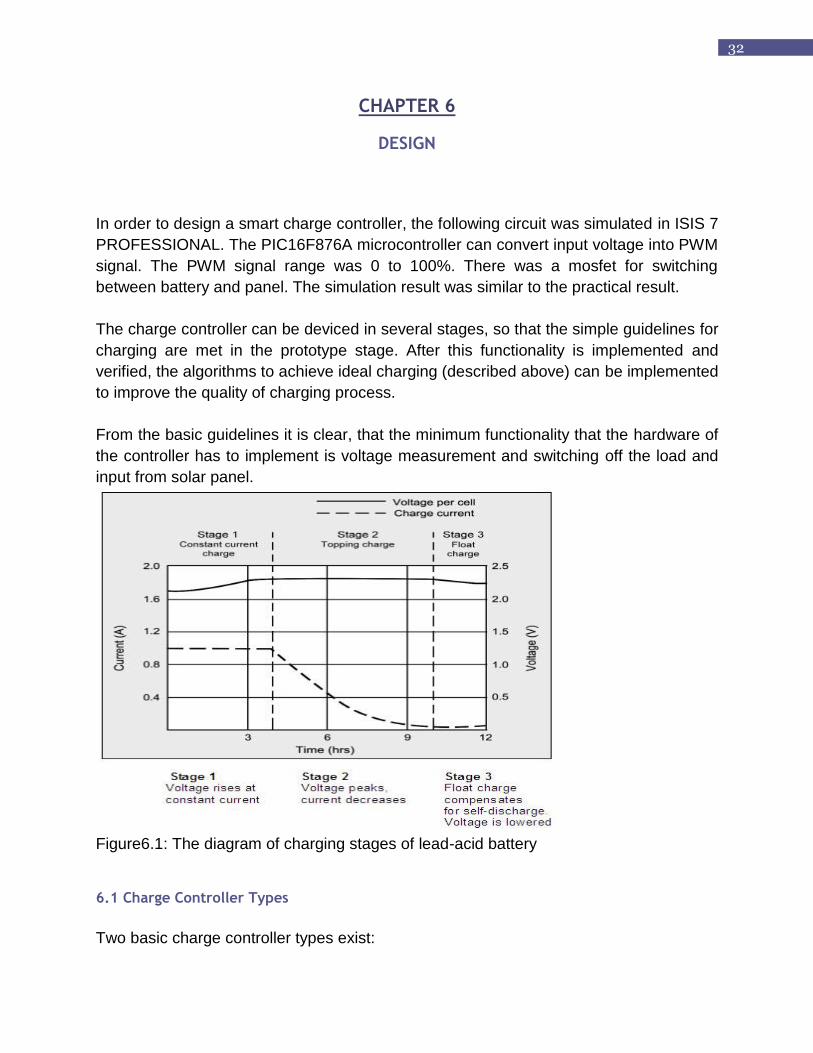
In order to design a smart charge controller, the following circuit was simulated in ISIS 7
PROFESSIONAL. The PIC16F876A microcontroller can convert input voltage into PWM
signal. The PWM signal range was 0 to 100%. There was a mosfet for switching
between battery and panel. The simulation result was similar to the practical result.
The charge controller can be deviced in several stages, so that the simple guidelines for
charging are met in the prototype stage. After this functionality is implemented and
verified, the algorithms to achieve ideal charging (described above) can be implemented
to improve the quality of charging process.
From the basic guidelines it is clear, that the minimum functionality that the hardware of
the controller has to implement is voltage measurement and switching off the load and
input from solar panel.
Figure6.1: The diagram of charging stages of lead-acid battery
6.1 Charge Controller Types
Two basic charge controller types exist:

33
6.1.1 Shunt Controller
All shunt controllers must have a blocking diode in series between the battery and the
shunt element to prevent the battery from short-circuiting when the module is regulating.
Because there is some voltage drop between the module and controller and due to
wiring and resistance of the shunt element, the module is never entirely short circuited,
resulting in some power dissipation within the controller. For this reason, most shunt
controllers require a heat sink to dissipate power, and are generally limited to use in PV
systems with module currents less than 20 amps.[6]
Figure6.2: Shunt Controller
Shunt-Interrupting Design
The shunt-interrupting controller completely disconnects the array current in an interrupting or on-off fashion when the battery reaches the voltage regulation set point. When the battery decreases to the array reconnect voltage, the controller connects the array to resume charging the battery. This cycling between the regulation voltage and array reconnect voltage is why these controllers are often called „on-off‟ or „pulsing‟ controllers. Shunt-interrupting controllers are widely available and are low cost, however they are generally limited to use in systems with array currents less than 20 amps due to heat dissipation requirements. In general, on-off shunt controllers consume less power than series type controllers that use relays (discussed later), so they are best suited for small systems where even minor parasitic losses become a significant part of the system load. Shunt-interrupting charge controllers can be used on all battery types, however the way in which they apply power to the battery may not be optimal for all battery designs. In general, constant-voltage, PWM or linear controller designs are recommended by manufacturers of gelled and AGM lead-acid batteries. However, shunt-interrupting controllers are simple, low cost and perform well in most small stand-alone PV systems.

34
Shunt-Linear Design
Once a battery becomes nearly fully charged, a shunt-linear controller maintains the battery at near a fixed voltage by gradually shunting the array through a semiconductor regulation element. In some designs, a comparator circuit in the controller senses the battery voltage, and makes corresponding adjustments to the impedance of the shunt element, thus regulating the array current. In other designs, simple Zener power diodes are used, which are the limiting factor in the cost and power ratings for these controllers. There is generally more heat dissipation in a shunt-linear controller than in shunt-interrupting types. Shunt-linear controllers are popular for use with sealed VRLA batteries. This algorithm applies power to the battery in a preferential method for these types of batteries, by limiting the current while holding the battery at the regulation voltage.
6.1.2 Series Controller
In a series controller, a relay or solid-state switch either opens the circuit between the
module and the battery to discontinuing charging, or limits the current in a series-linear
manner to hold the battery voltage at a high value. In the simpler series interrupting
design, the controller reconnects the module to the battery once the battery falls to the
module reconnect voltage set point.[6]
Figure6.3: Series Controller
Functions of Battery Charge Controller
Series-Interrupting Design
The most simple series controller is the series-interrupting type, involving a one-step control, turning the array charging current either on or off. The charge controller constantly monitors battery voltage, and disconnects or open-circuits the array in series once the battery reaches the regulation voltage set point.

35
After a pre-set period of time, or when battery voltage drops to the array reconnect voltage set point, the array and battery are reconnected, and the cycle repeats. As the battery becomes more fully charged, the time for the battery voltage to reach the regulation voltage becomes shorter each cycle, so the amount of array current passed through to the battery becomes less each time. In this way, full charge is approached gradually in small steps or pulses, similar in operation to the shunt-interrupting type controller. The principle difference is the series or shunt mode by which the array is regulated. Similar to the shunt-interrupting type controller, the series-interrupting type designs are best suited for use with flooded batteries rather than the sealed VRLA types due to the way power is applied to the battery.
Series-Interrupting, 2-step, Constant-Current Design
This type of controller is similar to the series-interrupting type, however when the voltage regulation set point is reached, instead of totally interrupting the array current, a limited constant current remains applied to the battery. This „trickle charging‟ continues either for a pre-set period of time, or until the voltage drops to the array reconnect voltage due to load demand. Then full array current is once again allowed to flow, and the cycle repeats. Full charge is approached in a continuous fashion, instead of smaller steps as described above for the on-off type controllers. A load pulls down some two-stage controls increase array current immediately as battery voltage. Others keep the current at the small trickle charge level until the battery voltage has been pulled down below some intermediate value (usually 12.5-12.8 volts) before they allow full array current to resume.
6.2 Overcharge Protection
In a 12 V battery system the voltage vary between 10.5 volts and 14.4 volts, depending
on the actual state of charge of the battery, charge current, discharge current, type and
age of the battery.
When a normal full loaded battery and no charging or discharging current is flowing than the battery voltage is about 12.4 volts to 12.7 volts, when charging current is flowing the voltages jump to a higher level e.g. 13.7 V (depending on the current), when loads are switched on the voltage drops down to a lower lever e.g. 12.0volts or 11.8 volts (also depending on the current). The PV module produces energy and the current is flowing into the battery so voltage
level increases up to the range of 14.4 volts. Then the over charge protection starts the
work.
When the battery voltage level is 14.4 volts, the charge controller is switched off the
charging current or reduced it (by pulse wide modulation).
6.3 Deep Discharge Protection
When a battery is deeply discharged, the reaction in the battery occurs close to the grids, and weakens the bond between the active materials and the grids. When we deep discharge the battery repeatedly, loss of capacity and life will eventually occur. To protect battery from deep discharge, most charge controllers include an optional feature

36
to disconnect the system loads once the battery reaches a low voltage or low state of charge condition. If the voltage of the system falls below 11.5 volts for a period of minimum 20 sec than the charge controller will be switched off for minimum 30 seconds. Than all loads which are connected to the controller is off. If the battery voltage increase above 12.5volts for more than 20 seconds than the charge controller will be switched ON the loads again for a minimum time of 30 seconds. The delay of 30 seconds is integrated to protect the system against a swinging situation.
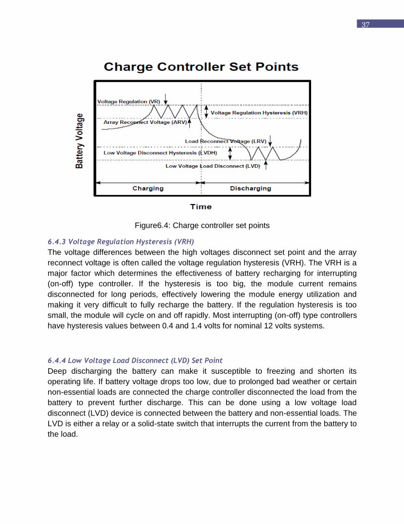
6.4 Charge Controller Set Points
Controller set points are the battery voltage levels at which a charge controller performs control or switching functions. Four basic control set points are defined for most charge controllers that have battery overcharge and overdischarge protection features. The voltage regulation (VR) and the array reconnect voltage (ARV) refer to the voltage set points at which the array is connected and disconnected from the battery. The low voltage load disconnect (LVD) and load reconnect voltage (LRV) refer to the voltage set points at which the load is disconnected from the battery to prevent overdischarge. Figure 12-1 shows the basic controller set points on a simplified diagram plotting battery voltage versus time for a charge and discharge cycle. A detailed discussion of each charge controller set point follows.
6.4.1 High Voltage Disconnect (HVD) Set Point
The high voltages disconnect (HVD) set point is one of the key specifications for charge
controllers. The voltage regulation set point is the maximum voltage that the charge
controller allows the battery to reach, limiting the overcharge of the battery. Once the
controller senses that the battery reaches the voltage regulation set point, the controller
will either discontinue battery charging or begin to regulate the amount of current
delivered to the battery.
6.4.2 Array Reconnect Voltage (ARV) Set Point
In interrupting (on-off) type controllers, once the module or array current is disconnected
at the voltage regulation set point, the battery voltage will begin to decrease. If the
charge and discharge rates are high, the battery voltage will decrease at a greater rate
when the battery voltage decreases to a predefined voltage, the module is again
reconnected to the battery for charging. The voltage at which the module is reconnected
is defined as the array reconnects voltage (ARV) set point.
37
Figure6.4: Charge controller set points
6.4.3 Voltage Regulation Hysteresis (VRH)
The voltage differences between the high voltages disconnect set point and the array
reconnect voltage is often called the voltage regulation hysteresis (VRH). The VRH is a
major factor which determines the effectiveness of battery recharging for interrupting
(on-off) type controller. If the hysteresis is too big, the module current remains
disconnected for long periods, effectively lowering the module energy utilization and
making it very difficult to fully recharge the battery. If the regulation hysteresis is too
small, the module will cycle on and off rapidly. Most interrupting (on-off) type controllers
have hysteresis values between 0.4 and 1.4 volts for nominal 12 volts systems.
6.4.4 Low Voltage Load Disconnect (LVD) Set Point
Deep discharging the battery can make it susceptible to freezing and shorten its
operating life. If battery voltage drops too low, due to prolonged bad weather or certain
non-essential loads are connected the charge controller disconnected the load from the
battery to prevent further discharge. This can be done using a low voltage load
disconnect (LVD) device is connected between the battery and non-essential loads. The
LVD is either a relay or a solid-state switch that interrupts the current from the battery to
the load.
38
6.4.5 Load Reconnect Voltage (LRV) Set Point
The battery voltage at which a controller allows the load to be reconnected to the
battery is called the load reconnect voltage (LRV). After the controller disconnects the
load from the battery at the LVD set point, the battery voltage rises to its open-circuit
voltage. When the PV module connected for charging, the battery voltage rises even
more. At some point, the controller senses that the battery voltage and state of charge
are high enough to reconnect the load, called the load reconnect voltage set point. LRV
should be 0.08 V/cell (or 0.5 V per 12 V) (see [1]) higher than the load-disconnection
voltage. Typically LVD set points used in small PV systems are between 12.5 volts and
13.0 volts for most nominal 12 volt lead-acid battery. If the LRV set point is selected too
low, the load may be reconnected before the battery has been charged.
6.4.6 Low Voltage Load Disconnect Hysteresis (LVLH)
The voltage difference between the low voltage disconnect set point and the load
reconnect voltage is called the low voltage disconnect hysteresis. If the low voltage
disconnect hysteresis is too small, the load may cycle on and off rapidly at low battery
state-of-charge (SOC), possibly damaging the load or controller, and extending the time
it required to charge the battery fully. If the low voltage disconnect hysteresis is too
large the load may remain off for extended periods until the array fully recharges the
battery.
6.4 Charger Circuit
The charger circuit for the SBCS project is microcontroller based and controls the
MOSFET switching. It follows the requirements stated above. It can automatically
disconect at HVD and recharge at LVD.

39
Figure6.5: The charger circuit
6.5 PCB Implementation
The PCB(Printed Circuit Board) was implemented to make the charge controller board.

40
Figure6.6: PCB Implementation
41
CHAPTER 7
INTERFACING
7.1 Why Interfacing?
The data acquisition card USB-4716 provides a device driver which gives different
functionality of the system. The device driver software-Active DAQ Pro gives different
function to use the DAQ system and represent the data. The functions primarily
classified as two categories which are Active DAQ Pro device control and Active DAQ
Pro GUI control. We have used the device control functions to manipulate the data
coming through the DAQ card .We integrated the device control function to our
Graphical User Interface to control the data coming from the DAQ card.
7.3 How to Interface
Interfacing between the DAQ card and the visual studio 2010 edition that we are using
is most important part in the project. The card takes the data from the charge controller
and sends the data to the computer. The computer gets a digital data and software
takes the responsibility for further processing of the data and shows it in specific
manner. It is versatile to ensure the communication between the software and the card
thereby. The steps of performing the interfacing are given below:
Although we are not using Active DAQ Pro-the device driver software
provided by the manufacturer company Advantech, we have to make
sure that it is working properly as we are not re-writing the built in GUI,
we are just grabbing necessary signals from the built in GUI.
Therefore, first step is to install the software to we make sure that the
windows will recognize the hardware. It just recognizes the hardware
and creates communication with the developed software.
Choose the necessary .dll functions needed to process the signal via
our newly built GUI using the provided one.
Needs the analog signal processing function AdvAI. As we used C#
language for the graphical user interface we added the specified
functions in C# development environment as reference. Here we are
using VISUAL STUDIO 2010 version.
42
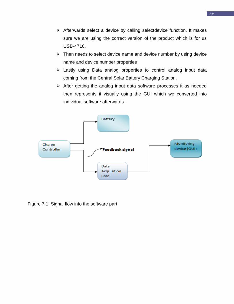
Afterwards select a device by calling selectdevice function. It makes
sure we are using the correct version of the product which is for us
USB-4716.
Then needs to select device name and device number by using device
name and device number properties
Lastly using Data analog properties to control analog input data
coming from the Central Solar Battery Charging Station.
After getting the analog input data software processes it as needed
then represents it visually using the GUI which we converted into
individual software afterwards.
Figure 7.1: Signal flow into the software part

43
CHAPTER 8
EXPERIMENTAL RESULT
8.1 Balance of System (BOS):
BOS stands for balance of system, which is used for all non-photovoltaic parts of a PV
system. They contribute significantly to the overall system and getting these wrong can
seriously damage the system. BOS components can be separated into electrical and
mechanical components.
The electrical components are:
• Cables
• Fuses
• Earthing
• Lightning Protection
• Battery
• Charge Regulation
Mechanical components are module support structure and tracing system.
8.2 Experiment on Different Charge Controller
Two different battery charge controller (a) Rahimafrooz charge controller, (b) Galchip
charge controller both product of Bangladesh have been collected and tested. We
observed the behaviour of the two different charge controllers.
The galchip charge controller was tested for primary requirements. It was tested for over
current and overcharged protection. It did not have the IDCOL protections. It did not
have the reverse leakage current.
Figure8.1: Off load test
Off Load Test:
Vrb Ib P
4.98 5.83 29.03
44
6 7.08 42.48
6.96 8.24 57.35
7.99 8.92 71.271
8.97 9.5 85.22
9.93 10.01 99.399
10.91 11.38 124.156
11.9 7.08 84.25
12.96 7.69 99.66
13.97 8.28 115.672
14.96 9.4 140.62
15.89 9.95 158.106
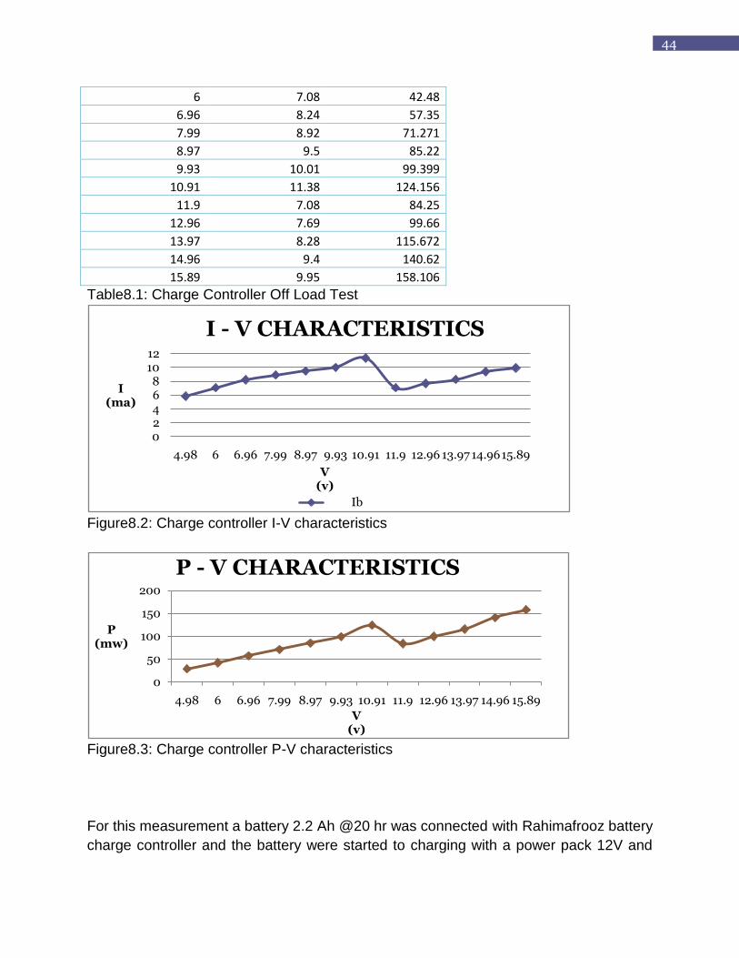
Table8.1: Charge Controller Off Load Test
Figure8.2: Charge controller I-V characteristics
Figure8.3: Charge controller P-V characteristics
For this measurement a battery 2.2 Ah @20 hr was connected with Rahimafrooz battery
charge controller and the battery were started to charging with a power pack 12V and
02468
1012
4.98 6 6.96 7.99 8.97 9.93 10.91 11.9 12.96 13.97 14.9615.89
I(ma)
V(v)
I - V CHARACTERISTICS
Ib
0
50
100
150
200
4.98 6 6.96 7.99 8.97 9.93 10.91 11.9 12.96 13.97 14.96 15.89
P(mw)
V(v)
P - V CHARACTERISTICS
45
constant current 200mA. At the beginning the voltage increased. So current was feeding
into the battery. And the charge controller did not regulate and all the current was
feeding into the battery.
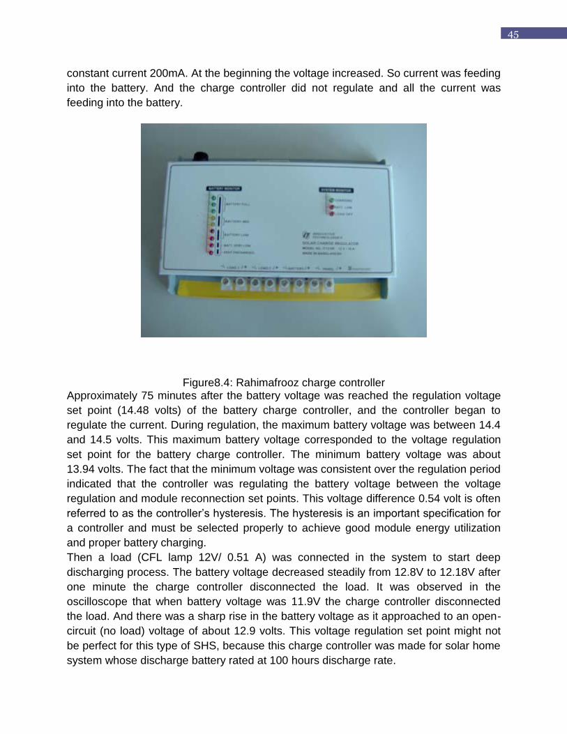
Figure8.4: Rahimafrooz charge controller Approximately 75 minutes after the battery voltage was reached the regulation voltage
set point (14.48 volts) of the battery charge controller, and the controller began to
regulate the current. During regulation, the maximum battery voltage was between 14.4
and 14.5 volts. This maximum battery voltage corresponded to the voltage regulation
set point for the battery charge controller. The minimum battery voltage was about
13.94 volts. The fact that the minimum voltage was consistent over the regulation period
indicated that the controller was regulating the battery voltage between the voltage
regulation and module reconnection set points. This voltage difference 0.54 volt is often
referred to as the controller‟s hysteresis. The hysteresis is an important specification for
a controller and must be selected properly to achieve good module energy utilization
and proper battery charging.
Then a load (CFL lamp 12V/ 0.51 A) was connected in the system to start deep
discharging process. The battery voltage decreased steadily from 12.8V to 12.18V after
one minute the charge controller disconnected the load. It was observed in the
oscilloscope that when battery voltage was 11.9V the charge controller disconnected
the load. And there was a sharp rise in the battery voltage as it approached to an open-
circuit (no load) voltage of about 12.9 volts. This voltage regulation set point might not
be perfect for this type of SHS, because this charge controller was made for solar home
system whose discharge battery rated at 100 hours discharge rate.

46
Figure8.5: Circuit of the Rahimafrooz charge controller
The charge controller cover was removed and found the circuit diagram shown in figure
8.5. It was found that there were five variable resistances, one of them for adjustment
high voltages disconnect set point and another one was adjusting for the deep
discharge disconnects set point. Again it was connected the load and the battery to the
system and adjusting the variable resistance for deep discharge protection with the help
of oscilloscope. It was fixed the deep discharge disconnect set point in11.5volts and
load reconnection voltage set point in 12.5volts.
8.3 Laboratory Test Result
The simulation is the same as the actual test. The pulse shows the value that is needed
to charge the battery. At different stages, the PWM duty cycle needs to be adjusted to
control the battery charging. It is able to disconnect the battery at High Voltage
Disconnect (HVD) and Low Voltage Disconnect (LVD).

47
Not Charging:
When voltage is below 10.5V
Duty cycle used: 0 %.
Figure8.6: No charge wave shape
Bulk Charge:
40% Ah to be used. It is when voltage is between 10.6 V to 12.6V.
Duty cycle used: 90 %
Figure8.7: Bulk charging wave shape
Float Charge:
5 percent of Ah to be used. It is when voltage is between 12.6 V to 14.3V.
Duty cycle used: 10 percent.
Figure8.8: Float charging wave shape

48
Full Charge(HVD):
Duty cycle used:0 %
When the battery voltage is 14.4V, circuit is open, the charging current is 0 A.
Figure8.9: Full charge wave shape

49
CHAPTER 9
CONCLUSION
The emergent need for electricity has led to a countrywide propagation of solar energy
based electricity generation systems that integrate battery storage through the use of
Solar Home Systems (SHSs) and a large portion of the country‟s population is
dependent on a strenuous means of livelihood that is rickshaw (tricycle) pulling[5]. To
tackle the problem, implementation of Solar Battery Charging Station (SBCS) has
emerged to the rural Bangladesh as well as in urban areas to change the scenario.
Thereby, software implementation of SBCS is vitally important to monitor the system
and keep the batteries safe. While maintaining the batteries of the SBCS manually,
there might occurs mistakes and batteries can get overcharged. But doing it using
software is not only safe but also time and cost effective. Thereby our motto is to make
the cost-effective software for monitoring the station from remote region even-though.
With the completion of our GUI we will be able to screen multiple batteries concurrently
under the same monitor and will allow for the real time visualization of all types of
readings, such as the voltage and percentage charge of each battery.
9.1 Boundaries Of The Current Job
The present charge controller can charge the battery but it has many restrictions.
1. There are many times when current overflow occurred.
2. It also faced burnout.
3. The pcb is not so efficient.

50
9.2 Future Work
There are many oppurtunities ahead. The project can be a great prototype project in
near future. Only some modifications can make great changes.
• 12V charger to be upgraded to 48 V later(few modifications required, easier than
back calculation).
• Using a backup diesel generator.
• Making it more efficient so that it can resist burnout and current overflow.
• Building larger solar charging station connected to the national grid system to
meet up increasing demand of load
• Vehicle charging, portable solar mobile phone chargers can be improved
• Building larger solar charging station connected to the national grid system to
meet up increasing demand of load
• Can be used to make advanced charge controllers for advanced use

51
REFERENCES
1. http://bdoza.wordpress.com/2009/05/11/solar-energy-alternative-source-of-energy-
for-bangladesh/
2. http://en.wikipedia.org/wiki
3. Infrastructure Development Company Limited (IDCOL) Bangladesh. URL:
http://www.idcol.org/energyProject.php
4. A N M Zobayer et al, Thesis on “Miniaturized Solar Home System For Lighting
Purpose With Light Emitting Diodes”, Carl von Ossietzky University
,Oldenburg/Germany & Center for Solar Energy and Hydrogen Research (ZSW)
,Baden-Württemberg, Stuttgart /Germany
5. Rachaen M. Huq et al, Thesis on “Development of Torque Sensor Based Electrically
Assisted Hybrid Rickshaw,” CARG Project, BRAC University
6. James P. Dunlop, P.E. et al, “Batteries and Charge Controller In Stand-Alone
Photovoltaic Systems fundamentals and applications”

52
APPENDICES
PIC 16F876A datasheet:
Pin Diagram:
PWM:

53
54
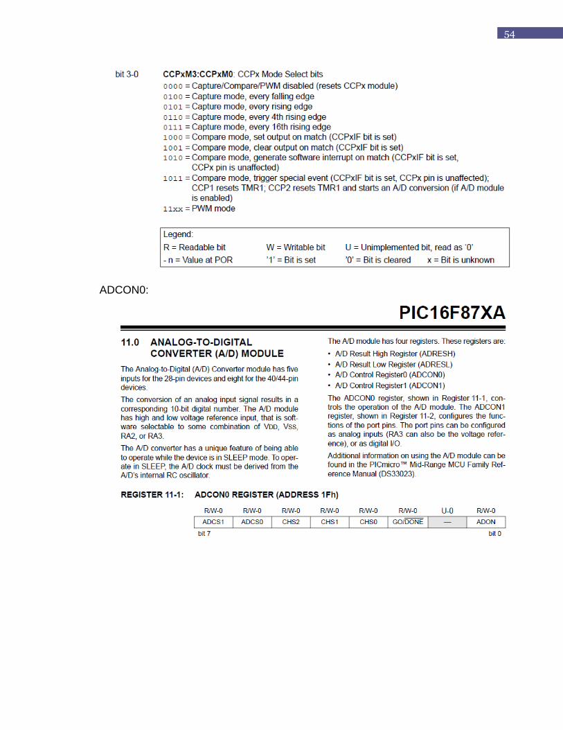
ADCON0:

55