Embed Size (px)
Citation preview
Designing Synchronization Sources in a Network
Element
Dejan Habic
Raltron Electronics Corp.
Agenda
A generic timing system solution in NE Clock cards architecture Line cards synchronization sources Performance Evaluation and test results examples
HF PLL
Line Card 2
Framer
(OCx)
PLL
Line Card n+1
Framer
(DSx)
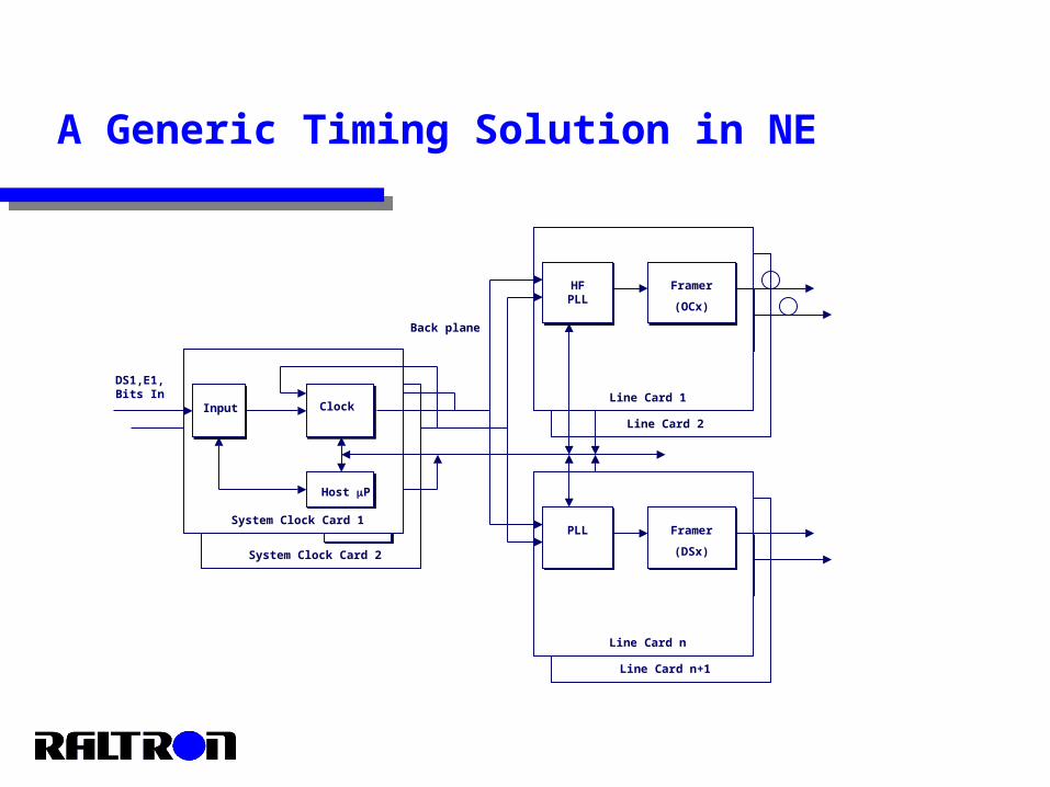
A Generic Timing Solution in NE
Input Clock
System Clock Card 2
Host P
Input Clock
System Clock Card 1
Host P
DS1,E1,Bits In
HF PLL
Line Card 1
Framer
(OCx)
PLL
Line Card n
Framer
(DSx)
Back plane
Functionality Performance Redundancy or overall robustness of the system. Automatic respond to all external or internal events at all levels. Alarm and status signal messages. Control interface to the all elements of the system.
A Generic Timing Solution – attributes
Number of external reference inputs Number of output signals required Selecting the local oscillator (LO) for required quality of the clock Filtering algorithms Reference qualification Phase transient suppression Holdover performance Switching between the modes Master-slave operation of the two clocks
Clock Card Architecture - general issues
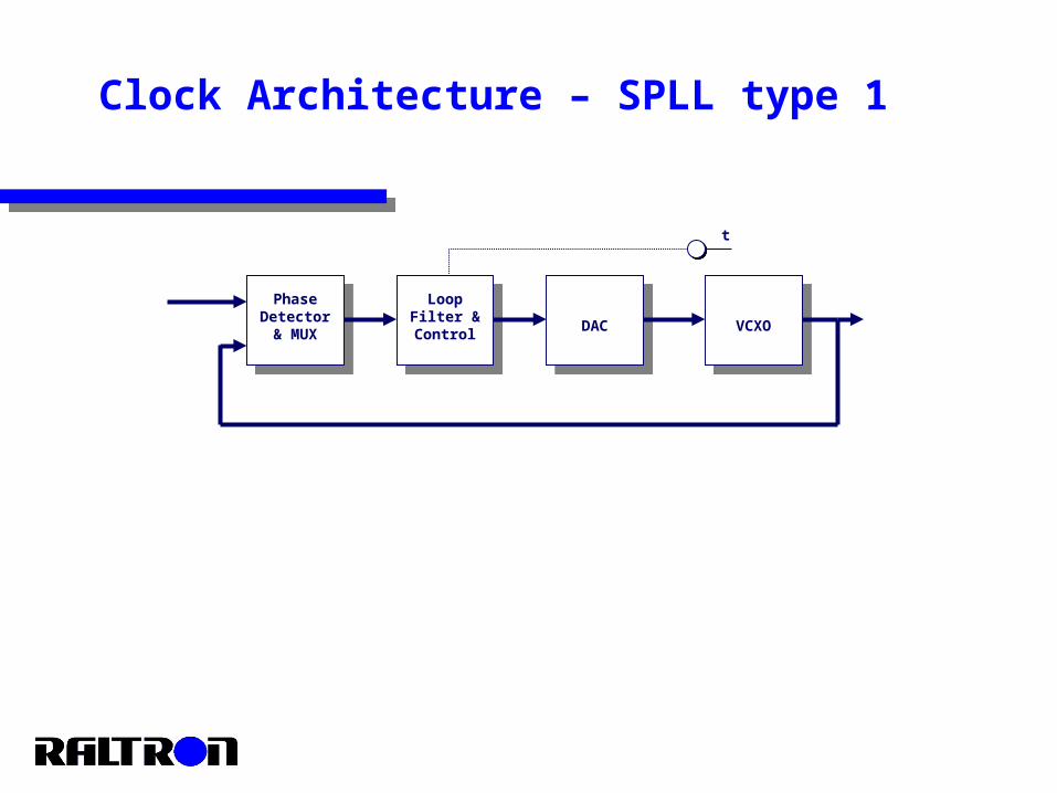
Phase Detector & MUX VCXODAC
Loop Filter & Control
t
Clock Architecture – SPLL type 1
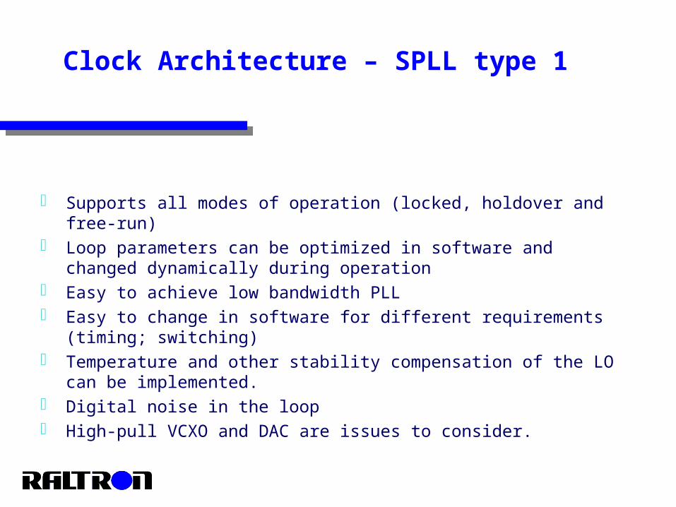
Supports all modes of operation (locked, holdover and free-run) Loop parameters can be optimized in software and changed
dynamically during operation Easy to achieve low bandwidth PLL Easy to change in software for different requirements (timing;
switching) Temperature and other stability compensation of the LO can be
implemented. Digital noise in the loop High-pull VCXO and DAC are issues to consider.
Clock Architecture – SPLL type 1
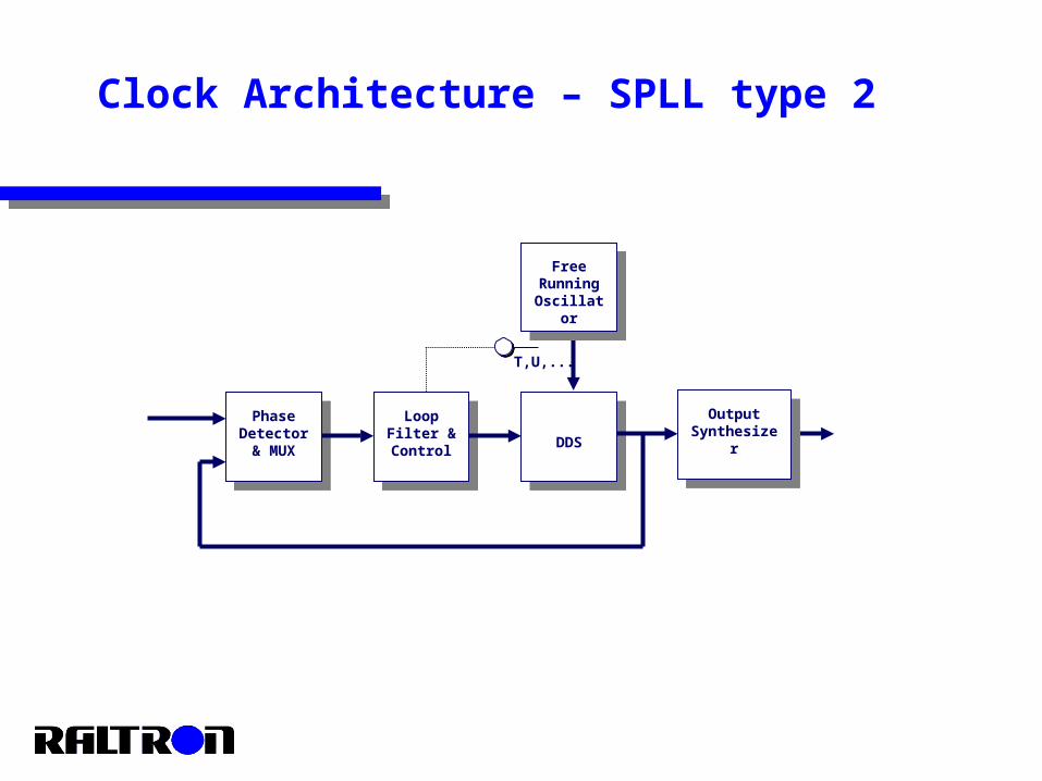
T,U,...
Phase Detector & MUX
Free Running Oscillato
r
DDS
Loop Filter & Control
Output Synthesize
r
Clock Architecture – SPLL type 2
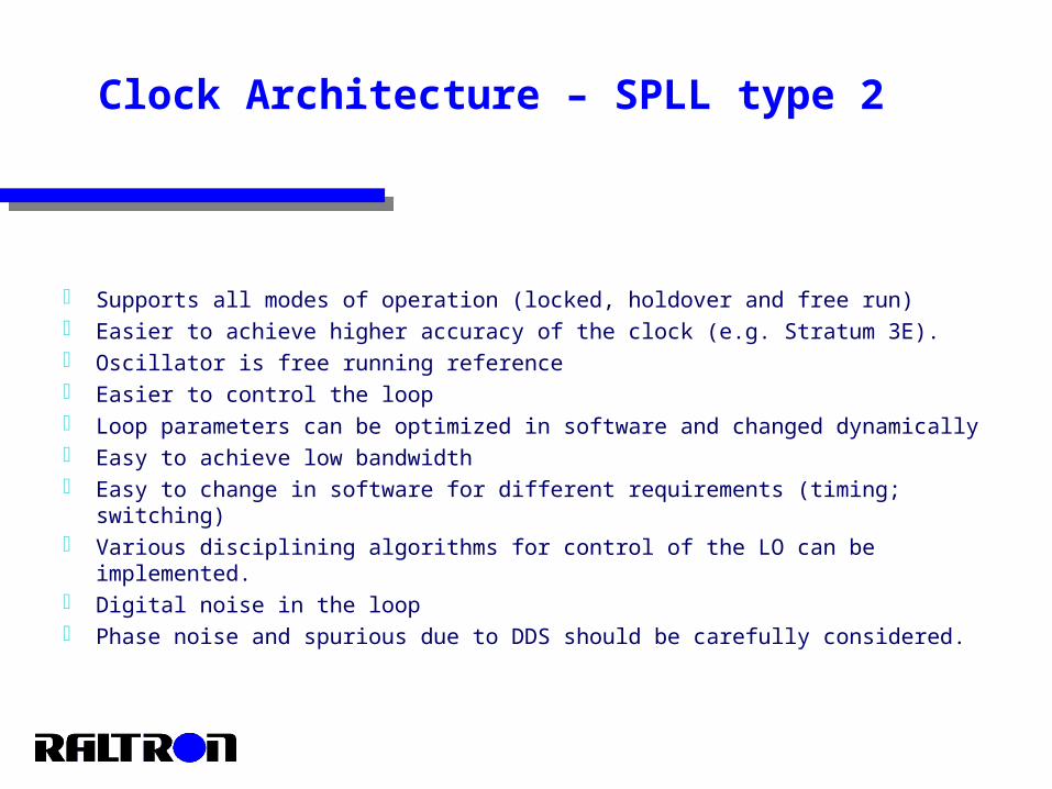
Supports all modes of operation (locked, holdover and free run) Easier to achieve higher accuracy of the clock (e.g. Stratum 3E). Oscillator is free running reference Easier to control the loop Loop parameters can be optimized in software and changed dynamically Easy to achieve low bandwidth Easy to change in software for different requirements (timing; switching) Various disciplining algorithms for control of the LO can be implemented. Digital noise in the loop Phase noise and spurious due to DDS should be carefully considered.
Clock Architecture – SPLL type 2
Line Cards Timing – General Issues
Generate highest possible frequency required by system with the cleanest output signal – crystal or SAW based oscillators.
The output oscillator should be with very good jitter performance – avoid signal multiplication if possible, using high frequency fundamental crystal technologies
The PLL should be optimized with respect to in/output frequencies, possible transients during switching etc…
Should provide smooth switching between two references. Should provide control interface, statuses and alarm messages.
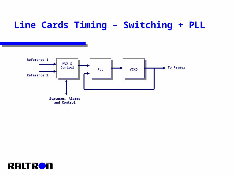
MUX & Control
VCXOPLL
Line Cards Timing – Switching + PLL
Reference 1
Reference 2
To Framer
Statuses, Alarmsand Control
Simple analog implementation of PLL with low jitter frequency source at the output.
Provide automatic switching between two references. Possible to implement a “hit-less” switching. Interface for status, control and monitoring. Different frequency sources require new optimizations of the loop. Influence of temperature, aging and other environmental effects
on the frequency source should be considered.
Line Cards Timing – Switching + PLL
Characterizing the behavior of the system
Parameters and behavior are well defined and specified by international recommendations (BellCore, ANSI, ITU-T, ETSI).
Important to ensure that the system complies with the recommendations.
Prove system performance.
Measurement and Analysis
Determine measurement equipment Determine set up of the equipment for specific measurements Follow the measurement procedures Measurements Analysis and interpreting the results
The types of measurements
Frequency accuracy – (ppm) Pull-in, Hold-in… – (ppm) Jitter and wander generation (TIE, MTIE, TDEV) Wander tolerance – (TIE, MTIE, TDEV) Holdover performance – (TIE, MTIE, f(T,t)…) Switching and transient – (TIE, MTIE) Other tests such as environmental tests…
Measurement – wander generation
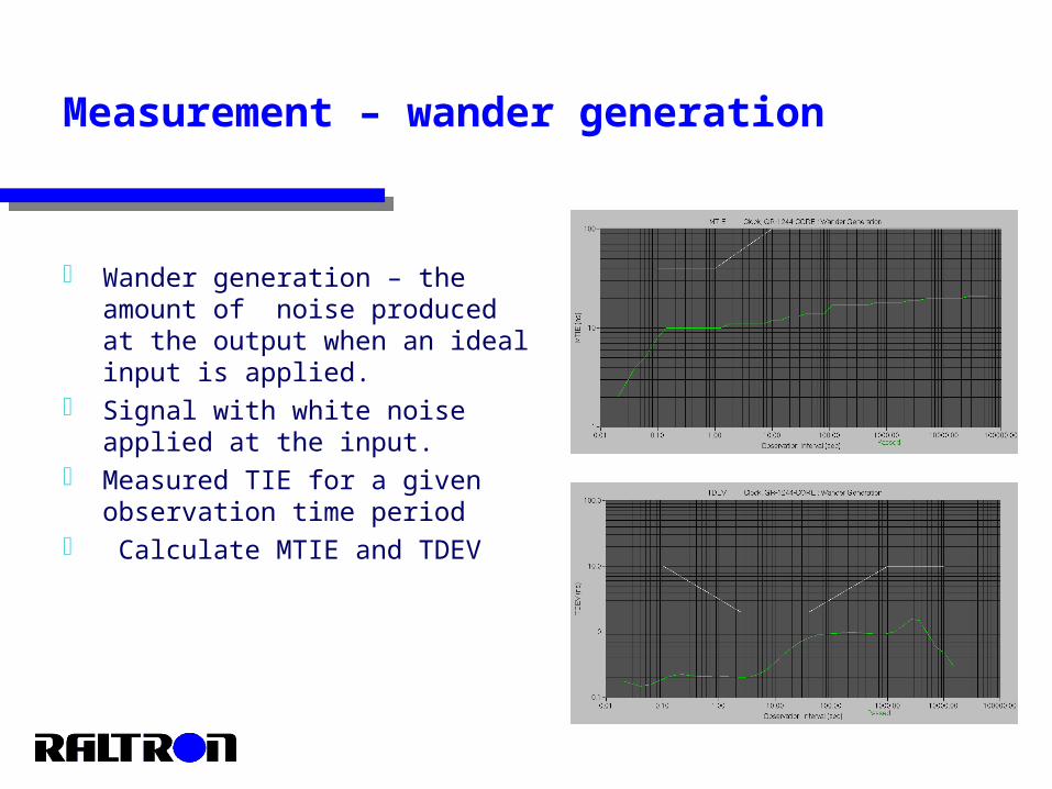
Wander generation – the amount of noise produced at the output when an ideal input is applied.
Signal with white noise applied at the input.
Measured TIE for a given observation time period
Calculate MTIE and TDEV
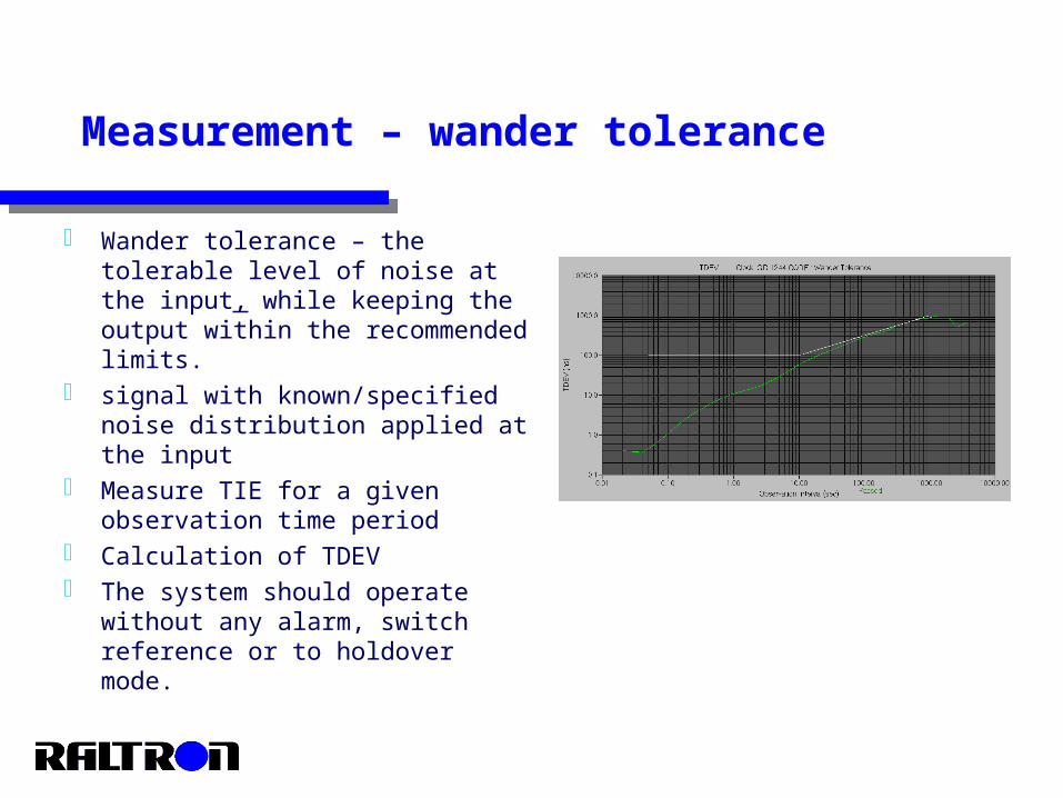
Wander tolerance – the tolerable level of noise at the input, while keeping the output within the recommended limits.
signal with known/specified noise distribution applied at the input
Measure TIE for a given observation time period
Calculation of TDEV The system should operate
without any alarm, switch reference or to holdover mode.
Measurement – wander tolerance
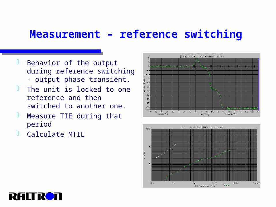
Behavior of the output during reference switching - output phase transient.
The unit is locked to one reference and then switched to another one.
Measure TIE during that period Calculate MTIE
Measurement – reference switching
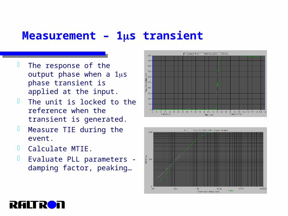
The response of the output phase when a 1s phase transient is applied at the input.
The unit is locked to the reference when the transient is generated.
Measure TIE during the event. Calculate MTIE. Evaluate PLL parameters -
damping factor, peaking…
Measurement – 1s transient
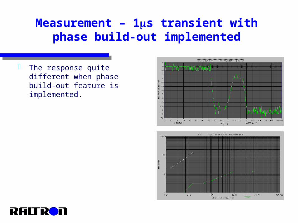
The response quite different when phase build-out feature is implemented.
Measurement – 1s transient with phase build-out implemented
The whole set of test that characterize holdover operation. Initial frequency offset. The frequency offset due to temperature changes. The frequency offset due to aging. The additional frequency offset.
Measurement – holdover performance
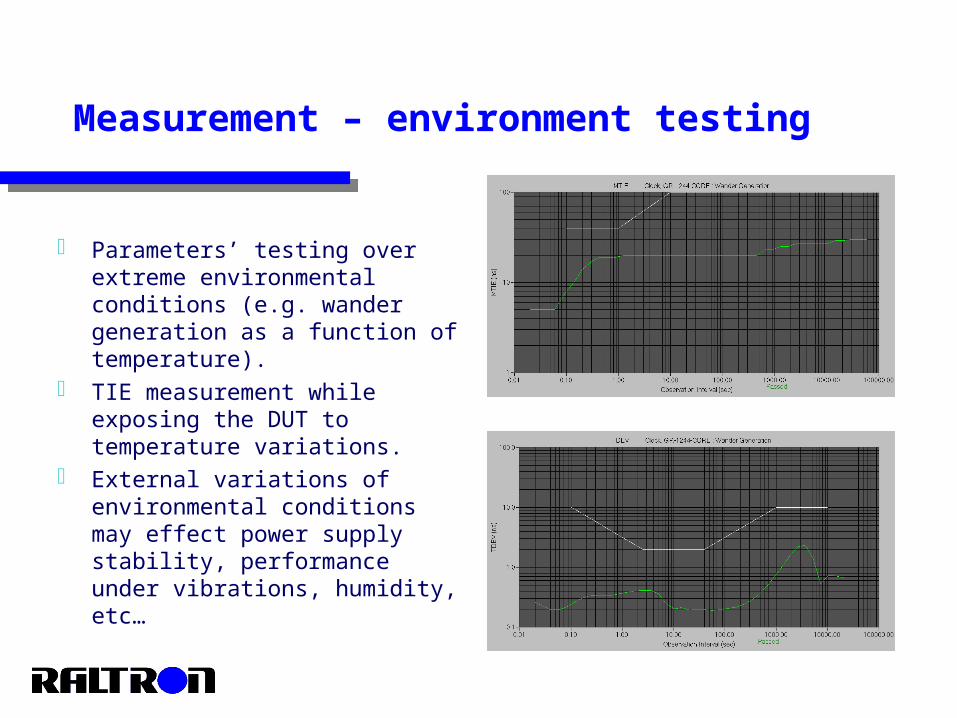
Parameters’ testing over extreme environmental conditions (e.g. wander generation as a function of temperature).
TIE measurement while exposing the DUT to temperature variations.
External variations of environmental conditions may effect power supply stability, performance under vibrations, humidity, etc…
Measurement – environment testing
Summary
Understand all the requirements of synchronization for a particular product.
Determine specifications and performances to be achieved. Determine the role of each element in the system and integration
impact amongst them. Select and evaluate each components in the system. Integrate a system. Test and characterize it.