Embed Size (px)
Citation preview

Airframe C Detailed Design Review
Dan Graves Project Lead James Reepmeyer Lead Engineer Alex Funiciello Wing/Airfoil Engineer Brian Smaszcz Airframe Engineer Michael Hardbarger Electrical System Engineer
11/6/2009

Risk Analysis
ID Risk Item Effect Cause Likelihood
Severity
Importance Action to Minimize Risk Owner
1 Flight Test Failure
Team fails to meet project deliverable
Poor aircraft design, pilot error, etc. 3 3 9
Design aircraft and associated tests correctly. Study weather for optimal test conditions Lead Engineer
2
Wing spar does not prevent bending
Wings break off plane, catastrophic failure
Insufficient analysis on wing spar / wing loading. Poor selection of wing spare size / materials. 3 3 9
Perform wing loading analysis, ensure wing spar is sufficient to carry load, reduce wing length to reduce bending moment
Lead Engineer Aero Engineer Airframe Engineer
3 Wing bends in torsion
Flight control surfaces rendered ineffective, catastrophic failure
Poor wing mount, insufficient secondary wing spar 2 3 6
Perform torsional analysis on the wing mount and secondary wing spar, reduce wing chord to reduce torsional moment
Lead Engineer Aero Engineer Airframe Engineer
4
Meeting Project Deadlines
Project will run behind schedule, or project deliverables are not met
Poor planning and poor execution 3 2 6
Create proper schedules with an appropriate buffer time between dependent actions, keep all team members aware of work that needs to be done Team Lead
5 Servos are underpowered
Servos cannot move the flight control surfaces under aerodynamic load
Poor servo selection, poor servo mounting points / angle , control surfaces too large 2 2 4
Servos must be appropriately selected for plane / control surface size and airspeed
Aero Engineer and Controls Engineer
6 Plane fails to take off
Plane cannot reach required takeoff speed
Airfoil drag is too great, motor is not powerful enough to accelerate plane 2 2 4
Analyze motor selection for sufficient power, compare thrust and airfoil drag equations
Lead Engineer Airfoil Engineer Controls Engineer
7 Build Time Runs Over
Delay in meeting project deliverable, flight testing does not run on schedule
Poor scheduling and poor work habits 2 2 4
Begin build phase early and maintain positive team morale Team Lead
8
Servo disconnects in flight
Loss of flight control surface(s), catastrophic failure
Poorly secured wires, poorly anchored 1 3 3
Properly anchor all servos, properly secure all wires, Lead Engineer
9 Wings Detach from Plane
Wings break off plane, catastrophic failure
Poor connections, connection comes loose, wing loading too great 1 3 3
Re-enforce / analyze wing attachment. Use metal hardware in necessary for strength.
Lead Engineer Airframe Engineer
10 Component Redesign
Forced project redesign can force the project to run over deadlines
Aircraft was not designed with proper components 1 3 3
Smart aircraft design with proper backing analysis. Compliance with subsystem interface designs
Entire Team Lead Engineer
11 H1N1/Illness
Team members can fall behind in work Germs 3 1 3
Proper cleanliness and Hygiene Entire Team

12 Miscellaneous Damages/Theft
Loss of progress and time Negligence 1 3 3
Ensure all parts are properly stored and secured Entire Team
13 Budget Driven Redesign
Team will have to redesign aircraft systems, increasing time needed for completion
Improper knowledge of budget constraints or funding restricted 1 3 3
Have budget clearly defined and avoid expensive components where possible
Team Lead Lead Engineer
14 Rear Landing Gear Failure
Loss of ground control (steering), potential cargo / plane damage
Poor attachment, hole on the runway, 2 1 2
Ensure plane body / cargo can withstand a loss of rear landing gear. Select suitable landing gear for plane size and weight
Lead Engineer Airframe Engineer
15 Front Landing Gear Failure
Nose dive (prop damage), cargo damage, plane structural damage
Landing gear detaches from plane body 1 2 2
Re-enforce / analyze the landing gear mounts.
Lead Engineer Airframe Engineer
16 Wing fails to lift plane
Plane cannot take off on runway
Airfoil of insufficient size, wrong airfoil selected 1 2 2
Analyze airfoil selection in XRLF5
Lead Engineer Airfoil Engineer
17 Component Testing Failure
Delay in project deliverable or testing schedule
Faulty component or poor system design 1 2 2
Test parts early and properly design all critical systems Entire Team

18
Budget Increase Needed
Unable to purchase critical parts needed for aircraft design and build
Expensive design or over design 1 2 2
Have budget clearly defined and avoid expensive components where possible
Lead Engineer Team Lead
19 Part Lead Time
Parts required for assembly delay build progress
Parts were not ordered far enough in advance 2 1 2
Order parts at the end of MSDI and make sure all parts are ordered
Team Lead Lead Engineer
20 Team Member Injury
Team member can fall behind in work resulting in a progress delay Multiple 1 2 2
Every team member acts in a responsible manner ensure work is done in a timely manner Entire Team
21 Critical Data Loss
Component re-design or re-analysis necessary
Hard drive failure, Lost flash drive 1 2 2
All documents are backed up and on EDGE Entire Team
22 Winter Break Start Up
Ramp up time for project build is longer due to winter break
The break between Fall and Spring quarters 1 2 2
Continue work and send project updates during the winter quarter Entire Team
23 P10662 Project Failure
Camera used for testing is not prepared for flight testing
Improper design to fit into airplane, design is unfinished or unable to function 2 1 2
Use an alternate camera system for aerial imagery Project Lead
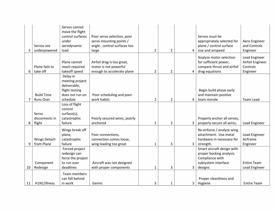
Mission Statement
The goal of the UAV Airframe C project is to provide an unmanned aerial platform used for an
aerial imaging system. The airframe must support the weight and interfaces for the designed imaging
system. The aircraft must be operated remotely and be a viable alternative to current aerial imaging
methods. This is a second generation airframe, expanding on the previously laid ground work
established by the P09232 UAV B Senior Design Project.
Key Project Goals
Airframe must be able to carry a fifteen pound payload
Easy integration with measurement controls box and different aerial imaging systems
Ability to remotely control aircraft and activate payload
Ability for flight communication between aircraft and ground relay
Aircraft provides twenty minutes of flight time for local area photography
Aircraft has the potential to take off and land on site
Easy assembly and disassembly of the aircraft for transportation
Lessons Learned from Airframe B
The aircraft’s wings sheared off shortly before impact. The failure was determined to be from
the bending stress applied to the wings during the banked turned.
After analysis, it was concluded that the main fiberglass spar used to support the wing was not
selected properly to handle the flight loading.
High bend in the wing during flight inhibited the pilot’s control of the aircraft by reducing the
effectiveness of the control surfaces.
Design Goals
Reduce wingspan (reduced bending moment)
Re-enforce wing spar
Reduce plane weight
Re-evaluate electric propulsion

Engineering Specifications
The following are the design specification for the Airframe C design.
1. The aircraft shall have a maximum weight of 25 lbs without payload (40 lbs gross)
2. The aircraft shall have a flight ceiling of 1000 ft
3. The aircraft shall be able to sustain a flight of at least 40mph in calm conditions
4. The aircraft shall be capable of stable flight with a 15 lb payload
5. The aircraft shall utilize an open architecture payload interface
6. The aircraft shall provide a mechanical interface to the payload
7. The aircraft shall provide a secure anchoring connection for the photographic
instrument payload
8. The aircraft shall provide a secure mounting location for the flight control electronics
package (P10236)
9. The aircraft shall sustain steady flight in a controllable manner for at least 20 minutes
10. The aircraft shall be able to re-launch as soon as it has been re-fueled or re-charged
11. The aircraft shall be able to operate for at least 12 regular flights without needing
routine maintenance
12. The aircraft shall be able to take off under its own power from a 1000 ft grass runway
o The aircraft shall have a sufficiently powerful motor
13. The aircraft shall be able to be transported in a motor vehicle when disassembled
14. The aircraft should be easy to assemble and disassemble by one person
15. The aircraft shall be able to navigate while on the ground
16. The final cost shall be less than the cost of renting a Cessna for a day (~$8000)
17. The aircraft should have similar flight characteristics to a trainer RC plane
18. The wing shall support the plane’s gross weight under +4/-2 G loading
o The wings shall not become detached from the plane while in flight
o The wings shall not deflect to a degree that interferes with the operation of the
flight control surfaces (will not jam the servos)
19. The propulsion system shall provide uninterrupted, constant power for at least 20 min
20. The landing gear shall hold the plane at an optimal angle of attack while on the ground
21. The servos shall be of sufficient power to control the plane’s control surfaces at speeds
up to 50 mph
22. The aircraft shall be structurally sound; no parts shall leave the aircraft while in flight

Wing Design
The primary cause of failure for last year’s Airframe B project was identified as a result of overloading
the main wing spar. This overloaded spar led to maneuverability issues with the plane, and its eventual
wing failure and crash.
Based on last year’s results, during the Airframe C risk analysis a similar failure is made the number one
concern. As such, in designing the airfoil, the primary objective is to lower the loading placed on the
spar. This can be achieved by reducing the total length of the wing, reducing the action arm of the wing
load about the wing root.
As Airframe B was able to successfully take off and climb to altitude, it is determined that similar takeoff
properties would be desirable this year. From talking with the customer, it was decided a takeoff speed
around 30 would be preferred.
In the initial wing selection, NASA’s FoilSim application was used on a variety of foil shapes, testing and
compared them to the foil used by Airframe B. In this comparison, the speed is fixed at 30mph while the
angle of attack is varied through the flight range. Different degrees of camber are tested to get an initial
idea of their impact.
After researching wing design for model airplanes, and speaking with several experienced members of
the model airplane community, it was decided that an aspect ratio of 8 or less should be used. Although
the higher the aspect ratio the more efficient the wing, creating ratios higher than 8 does not leave
adequate room for spar material and stringer placement. As such an aspect ratio of 7.5 is chosen as a
base point for further analysis.
Using FoilSim it is found that by using a highly cambered airfoil (9% camber) the total wing span can be
decreased from the 13ft span used in Airframe B to a 10ft span. Subsequently the chord would be
reduced from 18in to 16in. With the additional camber of this wing, the takeoff speed would remain the
same, at a similar angle of attack.
Using XFLR5 a wing model of the proposed wing (10ft span x 16in chord with a NACA 9412 section) is
compared to the Airframe B wing (13ft span x 18in chord with a Selig 7055 section). Both wings are
subjected to a constant load analysis with a total weight requirement of 40lbs (Figure 1 below). Using
XFLR it is shown that both wings lift off at near 30mph easily at reasonably low angles of attack (about 8
degrees). The new wing is shown to provide more lift than the old wing at lower angles of attack. This is
beneficial since it assures stall regions (high angles of attack) may be avoided.

Figure 1: Constant 40lb lift analysis: Flight Speed Required To Fly v. AOA
In comparing the bending moments experienced by both wings (Figure 2 below), it is clear that the new
wing has a marked improvement at all speeds, with a decrease in bending from an average of 57 lbft to
44 lbft.
Figure 2: Fixed Lift Wing Comparison: Bending Moment v. Flight Speed

To determine the optimum cruising speed of the wing, the Cl/Cd ratio is plotted against the plane speed
at a constant lift (Figure 3 below). From this plot it can be seen that the optimum Cl/Cd ratio occurs at a
speed of about 41 mph. This speed is similar to that of the Airframe B project, and meets our customer
expectations.
Figure 3: Whole Plane Fixed Lift Analysis: Cl/Cd v. Flight Speed
At the determined cruise speed, an angle of attack of two degrees is required for level flight. Since the
plane will spend most of its flight at this speed, flying at a level altitude, the wing is oriented at a positive
two degree angle of attack relative to the fuselage axis. This allows for the most efficient use of the
propulsion system at cruise speeds, with the prop thrust parallel to the direction of flight, while
maintaining the required angle of attack.
The disadvantages of a high cambered wing are an increase in drag and an increase in pitching moment.
Looking at the difference in drag between the new foil design and last year’s design shows an increase in
drag of about 1 lb (Figure 4 below). This increase is actually lower than expected, as the decrease in
overall wing size lessened the drag impact of switching to a more aggressive foil. An analysis of the
power system determined that this increase in drag is acceptable, allowing the plane to reach its
required flight time. The trade off was made, sacrificing endurance (still achieving the specified flight
time) to mitigate the possibility of wing failure.

Figure 4: Fixed Lift Wing Comparison: Drag v. Flight Speed
The issue of increased pitching moment is addressed through the use of a tail. The planes horizontal tail
was sized based on the industry standard tail sizing presented in Raymer’s Aircraft Design. The tail size
is found using the equations:
Using these equations a horizontal surface area of 2.222 ft2 is chosen, with a vertical tail of 1.333 ft2.
Using these areas, the horizontal tail was designed such that the tail length is the same as the main wing
segment length. A tail of 4ft span with a chord of 7.5 in is chosen (Figure 5 below).
To eliminate the pitching that would be experienced by the plane at cruise speeds the tail is designed
such that the pitching moment would reach zero once cruise speed is achieved. The tail is placed at a
negative four degree angle of attack relative to the fuselage axis to meet this requirement.
Using the industry standards for airfoil control surface sizing, aileron, elevator, and rudder surfaces were
designed. The elevator has a chord of 3.375in and spans 3.6 feet (90%) of the horizontal tail. The
rudder is designed to be .4 times the vertical tail chord (3.2 in) and spans the entire vertical tail height.

Figure 5: Horizontal Tail
As the main wing is segmented, the ailerons are designed to fit within the outer wing segments. The
ailerons are made 2.5 ft, leaving 3 inches on either side of the ailerons for wing structural support
(Figure 6 below). With the ailerons occupying 50% the total wingspan, using industry standards, the
chord is selected to be 3 in.
Figure 6: Main Wing Dimensions
Although it is shown that the moment at cruise is zero with no control input required, it is important to
verify that at slower speed the plane can be flow at a level inclination. By modeling the wing with
actuated control surfaces it is shown that a zero moment may be obtained by actuation of the elevator
surfaces to their ½ way position in the positive direction (upwards). This allows another ½ of their
actuation in the positive direction to pitch the plane up to begin a steeper climb.

Propulsion System Design
Design Process Steps:
1. Create Mission Plan
2. Use Empirical Analysis to Get Approximate Size
3. Detailed Analysis Using Model
4. Select Appropriate Motor Size
5. Select Battery Size and Arrangement, Select Motor Controller and UBEC
6. Create Bill of Materials Including Total Price and Weight
Step 1.
- Needs to maintain altitude of 1000 feet for 20 minutes.
Figure 7, Flight Mission Plan
Step 2:
Use hobby aircraft model rules of thumb to empirically estimate motor size:
- 50W per pound of aircraft weight for takeoff
- 75W per pound of aircraft weight to “trainer”-like flight controls
- More power increases flight control performance
P10232 Estimations:

- Specifications call for a 40lbf aircraft
- Need 2000W to takeoff
- Need 3000W for “trainer”-like flight controls
Conclusion: Only motors which are 2000W or larger will be compared and analyzed further.
Step 3:
Basic kinematic model to determine forces on plane at various flight stages.
Takeoff Segment
Figure 8, Takeoff Force Analysis (grs.nasa.gov)
After summing the forces the forward acceleration of the plane is:
Equations for Thrust and Drag were provided from the XFoil analysis completed for the
whole aircraft. The coefficient of kinetic friction was found experimentally.
Coefficient of Friction Experiment – Attached weight to the landing gear system
to bring to the total weight up to about 40 pounds. We pulled the landing gear at a
constant velocity and angle on various surfaces. We then did a basic force analysis to
find the kinetic coefficient of friction the plane has with the ground. The estimated
kinetic coefficient of friction is .2.
Figure 9, Friction Free Body Diagram used for Coefficient of Friction Analysis (dept.physics.upenn.edu)
L)μ(WDragThrustg
Wa

Figure 10, Image of Test Setup
Climb Segment
The plane must climb to a height of 1000 feet. To accomplish this a steady climb angle
of 8 degrees is used. The acceleration was computed similarly to that of takeoff using
the force diagram shown in Figure 5.
Figure 11, Climb Force Diagram (www.grc.nasa.gov)
Cruise Segment
The plane must maintain the altitude of 1000 feet for 20 minutes. During this segment
the forces on the plane are balanced
Thrust=Drag
Lift=Weight

Figure 12, Cruise Force Diagram(www.grc.nasa.gov)
Landing Segment
The landing phase should use very little extra power from the power system so it was
just assumed to be an extension of the cruise segment.
A Matlab/simulink model was constructed which analyzed the flight segments of the
plane. The model outputs the time, distance, battery capacity used, velocity profile, for
each segment. However, during the analysis process it was determined that too many
of the variables which control the model were not definitively known. The thrust, lift,
drag, prop. Efficiency, friction, and current draw were all not known with enough
certainty to validate the effect of the model.
This resulted in using the empirical estimates to make a motor size selection.
Step 4:
Motor Size Selection
The motor selected for the aircraft is the Turnigy AerodriveXp SK Series 63-74. The
motor outputs 3200W which is more than enough for our application.
Step 5:
Battery Selection
The motor requires 37V (10s Lipo) and draws 65A. To get the required flight time we
need four 18.5V Lithium-Ion Polymer ZippyMax Flight 5000mAh battery packs. The
packs will be paired in series to get the total voltage up to 37V. The two strings of
batteries will be connected in parallel to get a total capacity of 10000mAh.
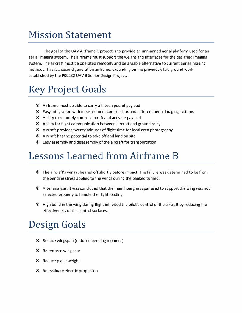
Step 6:
ESC Selection:
The batteries will power an electronic speed controller (ESC) which will power the
motor. Our motor calls for an 100A ESC and the Turnifgy Sentilon 100A HV 5-12S BESC
was chosen for our application.
UBEC Selection:
It is recommended to use an Ultimate Battery Eliminator Circuit (UBEC) to power the
other components of the system. The one chosen for our system is the Turnigy 5-7.5A
HV UBEC of Lipoly.
Propeller Selection:
A motor our size calls for a larger propeller. The propeller suggested by our motor is the
XP Type B Propeller 24x10.
Step 7:
Bill of Materials:
Part Quantity Name Weight (lb)
Price ($US)
Total Weight (lb)
Total Price ($US)
Brushless Motor 1 AerodriveXp SK Series 63-74
1.85 59.99 1.851883002 59.99
Battery 4 ZIPPY MaxFlight 5000mAh 5S1P 15C
1.27 42.95 5.097087502 171.8
Speed Controller
1 Turnigy Sentilon 100A HV 5-12S BESC
0.28 99.99 0.275577828 99.99
UBEC 1 Turnigy 5-7.5A HV UBEC for Lipoly
0.08 19.95 0.081571037 19.95
Propeller 1 XP Type B 3D/SF Propeller 24x10
0.26 25.49 0.264554715 25.49
Total System Weight (lb) 7.57
Total System Price ($US) 377.22
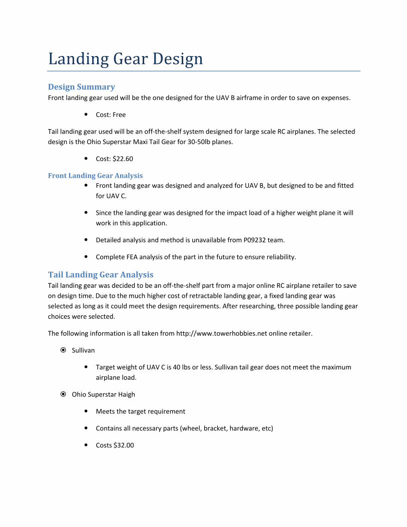
Landing Gear Design
Design Summary Front landing gear used will be the one designed for the UAV B airframe in order to save on expenses.
Cost: Free
Tail landing gear used will be an off-the-shelf system designed for large scale RC airplanes. The selected
design is the Ohio Superstar Maxi Tail Gear for 30-50lb planes.
Cost: $22.60
Front Landing Gear Analysis
Front landing gear was designed and analyzed for UAV B, but designed to be and fitted
for UAV C.
Since the landing gear was designed for the impact load of a higher weight plane it will
work in this application.
Detailed analysis and method is unavailable from P09232 team.
Complete FEA analysis of the part in the future to ensure reliability.
Tail Landing Gear Analysis Tail landing gear was decided to be an off-the-shelf part from a major online RC airplane retailer to save
on design time. Due to the much higher cost of retractable landing gear, a fixed landing gear was
selected as long as it could meet the design requirements. After researching, three possible landing gear
choices were selected.
The following information is all taken from http://www.towerhobbies.net online retailer.
Sullivan
Target weight of UAV C is 40 lbs or less. Sullivan tail gear does not meet the maximum
airplane load.
Ohio Superstar Haigh
Meets the target requirement
Contains all necessary parts (wheel, bracket, hardware, etc)
Costs $32.00

Ohio Superstar Maxi
Target weight of UAV C is 40 lbs or less. Sullivan tail gear does not meet this maximum
load.
Contains all necessary parts (wheel, bracket, hardware, etc)
Costs $22.60
Final Landing Gear Design The front landing gear will be the one designed for the UAV B. This is because it is readily available and
inexpensive.
Cost: Free
Tail landing gear will be the Ohio Superstar Maxi Tail Gear (30-50lb planes) because it meets the
necessary plane requirements while being the least expensive option.
Cost: $22.60
Total System Cost: $22.60

Main Wing Spar Design
Design Summary Dragon Plate braided carbon fiber circular tubing will be used as the main spar.
Cost: $237.00
Dimensions:
○ OD: 0.79”
○ ID: 0.54”
○ Length: 48”
Assumptions At steady, level flight the wing is loaded uniformly across the span.
Main spar supports the entire weight of the plane by itself.
From the wing root outwards the spar behaves as a cantilevered beam.
Normal flight load is 40 lbf
Design will be to 5 g acceleration per guidelines in the RCAdvisor’s Model Airplane
Design handbook. (Reyes, Carlos. Model Airplane Design Made Easy. Albuquerque:
RCadvisor, 2009.)
Due to symmetry, half the wing will be analyzed.
Design Considerations Must remain under materials yield strength
(elastic region) to avoid permanent deformation.
Must not deflect excessively at flight load
(less than 1 foot) in order for control surfaces to maintain effectiveness.
Must be light in order to keep the weight of the aircraft at a minimum.
Must be competitively priced compared to other options.

Material Selection Materials were selected that are readily available and have associated engineering data provided for
analysis. Fiber glass was not analyzed as reliable engineering data could not be provided. Steel was not
analyzed due to the high amount of weight that the spar would have to be.
Aluminum 2024-T6
Yield Strength: 50 ksi
Modulus of Elasticity: 10500 ksi
Material properties for Aluminum 2024-T6 are taken from http://www.matweb.com
Aluminum 6061-T6
Yield Strength: 40 ksi
Modulus of Elasticity: 10000 ksi
Material properties for Aluminum 2024-T6 are taken from http://www.matweb.com
Dragon Plate Braided Carbon Fiber
Yield Strength: 600 ksi
Modulus of Elasticity: 43000 ksi
Material properties for Dragon Plate braided carbon fiber are taken from http://www.dragonplate.com

Main Spar Load Diagram
The target design for the spar was initially a 0.75” OD with a 0.5” ID based off of last years design. Since
the braided carbon fiber material has the best tensile strength, a profile which was readily available was
selected for analysis.
Testing profile: OD: 0.79”
ID: 0.54”
All engineering equations are provided and referenced from: Budynas, and Nisbett. Shigley's Mechanical
Engineering Design. New York: McGraw-Hill, 2008

Calculations:
Stress at 1 g flight load
M = Moment of the Load
y = Maximum magnitude of the neutral axis
I = Moment of Area
Aluminum 2024-T6 at 1 g flight load
Dragon Plate carbon fiber at 1 g flight load
Stress at 5 g flight load

Aluminum 2024-T6 at 5 g flight load
Dragon Plate carbon fiber at 5 g flight load
Deflection at 1 g flight load
Beam deflection was solved for using the superposition method. Page 994 of (Budynas)
Reference: Budynas, and Nisbett. Shigley's Mechanical Engineering Design. New York: McGraw-Hill, 2008
Aluminum 2024-T6 deflection at 1 g flight load
Dragon Plate carbon fiber deflection at 1 g flight load
Deflection at 5 g flight load

Aluminum 2024-T6 deflection at 5 g flight load
Dragon Plate carbon fiber deflection at 5 g flight load
Weight of each spar
Aluminum 2024-T6 weight for 10 ft spar
2.55 lb
Dragon Plate carbon fiber weight for 10 ft spar
Cost of each spar
Aluminum 2024-T6 weight for 10 ft spar
Estimate based on Part No: 1968T336 provided from http://www.mcmaster.com
Dragon Plate carbon fiber weight for 10 ft spar
Final Design Specifications Dragon plate braided carbon fiber will be used as the main spar. As shown by the previous analysis, the
carbon fiber profile has excellent resistance to stress provided a high factor of safety, while also
reducing tip deflection of the wing far below that of Aluminum 2024-T6. Carbon fiber is also lower in
weight compared to Aluminum 2024-T6 but is only $87.24 difference in price. Therefore, given the
previous analysis, braided carbon fiber is best suited for the design.

Airframe Design
The goal for this aspect of the project is to reduce the weight without sacrificing structural rigidity. After
spending many hours in the Aero Club lab studying and building model airplanes, as well as talking with
the club members and gathering ideas, the concept was created. The plane is designed to be
constructed like a puzzle. Each piece interlocks with an adjacent part creating both a structurally sound
and rigid component. The entire frame consists of bulk heads cut from poplar lite-ply which are spaced
evenly down the length of the plane. Balsa wood stringers are then run the length of the plane attached
in notches cut into the bulk heads. This gives the plane resistance to bending that may occur. A thin
layer of balsa will also coat the plane like a skin which will further increase the airframes resistance to
bending as well as torsion. The final phase of skinning will include adding monocoque to decrease the
skin friction drag and further increase the planes rigidity.
Since one of the engineering specs of the project is to create an open architecture airframe, every
attempt was made to utilize any open volume and make it usable. This was done by creating floor
surfaces between bulk heads as well as specific compartments for components. For specific components
such as the camera system and power supply, compartments were created to the specific geometry for
these items. For all other open volumes we have created usable locations for mounting and moving
mass around to better balance the plane. These platforms are for use only if needed, however, they do
add torsional rigidity to the airframe.

Part Name Qty. Volume
(L W H) (in) Material
Component Weight (lbs)
Base Plate 1 16.5 3 0.25 1/4" Ply 0.32
Battery Bay 1 13 3.5 0.25 1/4" Ply 0.11
Battery Bracket 1 8.08 2.5 0.25 1/4" Ply 0.08
Battery Side 2 13 3.25 0.25 1/4" Ply 0.06
Camera Bracket 2 8 6.25 0.25 1/4" Ply 0.2
Landing Gear Side 2 2.5 1.5 0.25 1/4" Ply 0.01
Motor Firewall 1 8.5 8 0.25 1/4" Ply 0.19
Battery Bracket M 1 7.15 6.74 0.25 1/4" Ply 0.07
Battery Bracket F 1 5.75 5.5 0.25 1/4" Ply 0.05
Bolt Bolck 2 2.5 1 0.44 1/4" Ply 0.02
Motor Mount Back 1 3.25 3.5 0.25 1/4" Ply 0.05
Ply Firewall 1 8 8.5 0.25 1/4" Ply 0.2
Tail End Firewall 1 8 8.5 0.25 1/4" Ply 0.2
Tail Wall 1 1 8.17 7.8 0.25 1/4" Ply 0.16
Tail Wail 2 1 7.56 7.2 0.25 1/4" Ply 0.13
Tail Wall 3 1 6.53 6.19 0.25 1/4" Ply 0.12
Tail Wall 4 1 5.08 4.79 0.25 1/4" Ply 0.07
Tail Wall 5 1 3.45 2.97 0.25 1/4" Ply 0.03
Tail Wall 6 1 1.12 0.75 0.25 1/4" Ply <.01
Rear Shelf 1 9 7.32 0.25 1/4" Ply 0.22
Side Panel 2 16.5 5.25 0.25 1/4" Ply 0.17
Shelving 1 9 7.39 0.25 1/4" Ply 0.26
Shelf 2 1 9 7.2 0.25 1/4" Ply 0.2
Shelf 3 1 9 6.19 0.25 1/4" Ply 0.16
Shelf 4 1 9 4.79 0.25 1/4" Ply 0.13
Stringer 1 1 51.99 0.25 0.25 1/4" Balsa -
Stringer 2 1 69.39 0.25 0.25 1/4" Balsa -
Stringer 3 1 50.63 0.25 0.25 1/4" Balsa -
Stringer 4 1 67.89 0.25 0.25 1/4" Balsa -
Stringer 5 1 75.59 0.25 0.25 1/4" Balsa -
Stringer 6 1 16.86 0.25 0.25 1/4" Balsa -
Stringer 7 1 13.19 0.25 0.25 1/4" Balsa -
Total Weight of Balsa Stringers 0.37
Balsa Skin - 1972.46 in^2 1/32" Balsa 0.36
Total Weight (lbs) 3.94
Material Material Size Cost Qty Total Cost
Poplar Lite Ply 1/4x12x48 $8.83 197.64 129.58 0.25 44 $388.52
Balsa Sheet 1/32x12x48 $10.97 4 $43.88
Balsa Sticks 1/4x1/4x48 $0.44 345.54 0.25 0.25 8 $3.52
$435.92
Area
1972.46 in^2
Total Cost
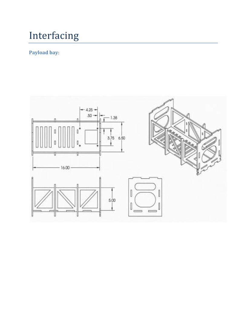
Interfacing
Payload bay:

Control Hardware Mount:
Front Landing Gear Mount

Wing Mount