Embed Size (px)
Citation preview
Journal of Physics Conference Series
OPEN ACCESS
Development and UHV testing of LN2 cooledTitanium Sublimation PumpTo cite this article B K Sindal et al 2012 J Phys Conf Ser 390 012022
View the article online for updates and enhancements
You may also like(Invited) Zirconia-Based ElectrochemicalOxygen Sensor for Monitoring Humidity atthe Cathode of PEM StacksRichard E Soltis
-
Pumping characteristics of a titaniumdroplet getter-ion pumpL Holland and L Laurenson
-
Pumping speed offered by activatedcarbon at liquid helium temperatures bysorbents adhered to indigenouslydeveloped hydroformed cryopanelRanjana Gangradey Samiran ShantiMukherjee Paresh Panchal et al
-
This content was downloaded from IP address 5996204 on 29112021 at 1019
Development and UHV testing of LN2 cooled Titanium Sublimation Pump
B K Sindal1 K V A N P S Kumar Tripti Bansod and S K Shukla
Ultra High Vacuum Technology Division RRCAT Indore - 452 013
E-mail bksindalrrcatgovin
Abstract Titanium sublimation pumps (TSP) provide inexpensive large pumping speeds for active gases especially in UHV environment where residual gases are mainly H2 and CO etc The pumping speed of TSP is independent of pressure in this range Sublimation of Ti on liquid nitrogen (LN2) cooled surfaces is expected to provide large porosity in deposited film and this may also result in further enhancement of its pumping speed Accordingly a liquid nitrogen cooled TSP was developed to achieve clean vacuum in 10-11 mbar range in combination of sputter ion pump which is mainly used to take care of inert gas load The LN2 shroud was designed to have 19 litre capacity and offered approximately 2000 cm2 cooled surface area with approximately 250cm2 area coated with titanium film This paper describes the performance of the TSP at room temperature as well as after cooling with LN2 Quadrupole mass analyzer was utilized to analyze residual gases Simultaneously for pumping speed measurements for different gasses a setup with known conductance was also appended
1 Introduction Titanium Sublimation Pumps (TSP) are mostly used to supplement the pumping of Sputter Ion Pumps They have low cost simple operation and provide very high pumping speed for active gases in UHV region We have used commercially available lsquoUrsquo shaped filaments made of Titanium-Molybdenum alloy (85+15) of Oslash21 mm and having 35 mΩ resistance Three filaments mounted on simple four pin low electrical resistance feed-through with the help of SS connectors (Figure 2) A high current passed through the filaments by a power supply causing its temperature to rise sufficiently and sublimate titanium from filament This sublimated titanium then gets coat the on wall of the vacuum chamber the film reacts with gas molecules within the system to form low vapour pressure compounds The saturation time of film depends upon pressure and types of gasses pumped The pumping efficiency of TSP increased many times by cooling of coated wall to liquid nitrogen temperature due to increase in sticking coefficient for gases on cooled surfaces especially for H2 which shows highest partial pressure in UHV region This paper describes the development works and pumping speed measurement for different gases (N2 H2 amp CO) at various pressures and at 300K as well as 77K
2 Development of UHV chambers
21 Design Titanium sublimation Pump body
International Symposium on Vacuum Science amp Technology and its Application for Accelerators IOP PublishingJournal of Physics Conference Series 390 (2012) 012022 doi1010881742-65963901012022
Published under licence by IOP Publishing Ltd 1
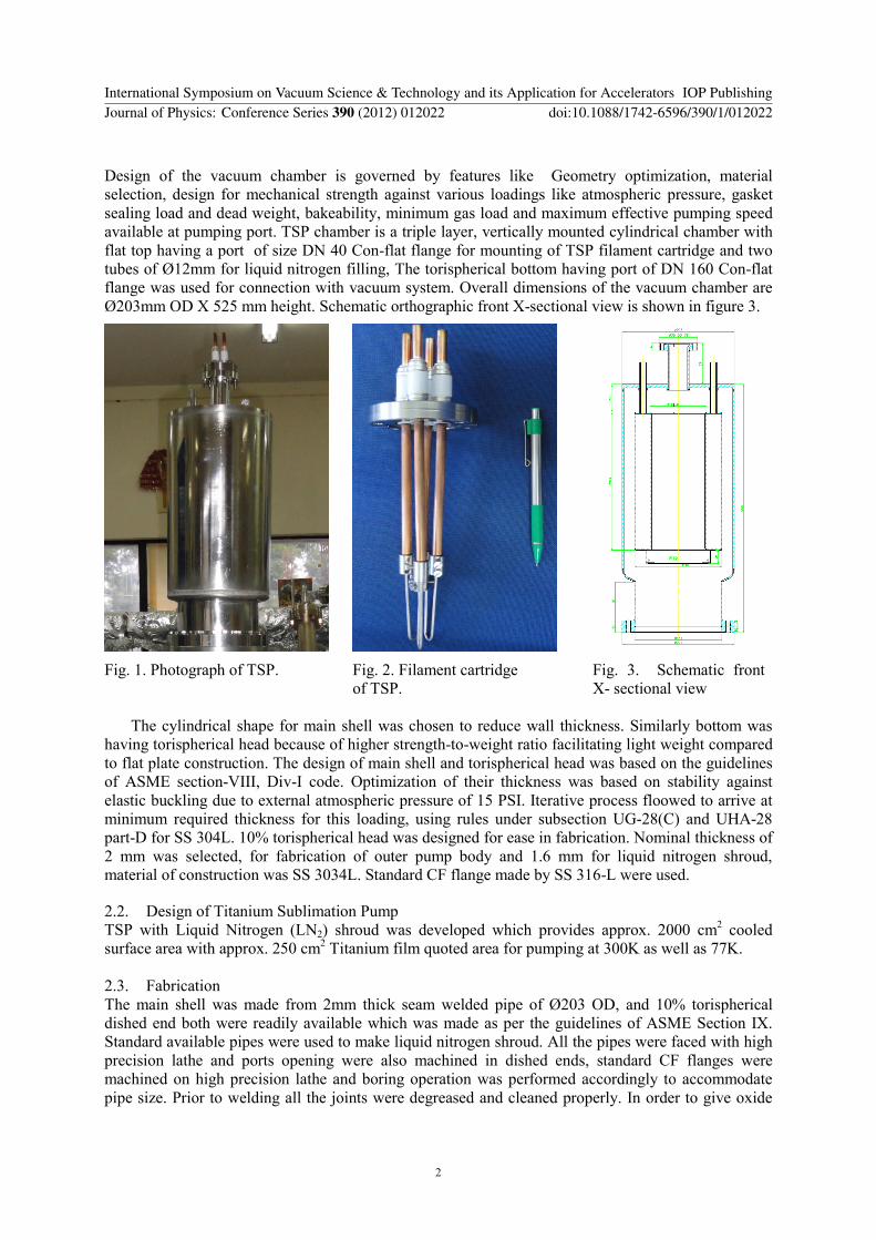
Design of the vacuum chamber is governed by features like Geometry optimization material selection design for mechanical strength against various loadings like atmospheric pressure gasket sealing load and dead weight bakeability minimum gas load and maximum effective pumping speed available at pumping port TSP chamber is a triple layer vertically mounted cylindrical chamber with flat top having a port of size DN 40 Con-flat flange for mounting of TSP filament cartridge and two tubes of Oslash12mm for liquid nitrogen filling The torispherical bottom having port of DN 160 Con-flat flange was used for connection with vacuum system Overall dimensions of the vacuum chamber are Oslash203mm OD X 525 mm height Schematic orthographic front X-sectional view is shown in figure 3
The cylindrical shape for main shell was chosen to reduce wall thickness Similarly bottom was
having torispherical head because of higher strength-to-weight ratio facilitating light weight compared to flat plate construction The design of main shell and torispherical head was based on the guidelines of ASME section-VIII Div-I code Optimization of their thickness was based on stability against elastic buckling due to external atmospheric pressure of 15 PSI Iterative process floowed to arrive at minimum required thickness for this loading using rules under subsection UG-28(C) and UHA-28 part-D for SS 304L 10 torispherical head was designed for ease in fabrication Nominal thickness of 2 mm was selected for fabrication of outer pump body and 16 mm for liquid nitrogen shroud material of construction was SS 3034L Standard CF flange made by SS 316-L were used
22 Design of Titanium Sublimation Pump TSP with Liquid Nitrogen (LN2) shroud was developed which provides approx 2000 cm2 cooled surface area with approx 250 cm2 Titanium film quoted area for pumping at 300K as well as 77K 23 Fabrication The main shell was made from 2mm thick seam welded pipe of Oslash203 OD and 10 torispherical dished end both were readily available which was made as per the guidelines of ASME Section IX Standard available pipes were used to make liquid nitrogen shroud All the pipes were faced with high precision lathe and ports opening were also machined in dished ends standard CF flanges were machined on high precision lathe and boring operation was performed accordingly to accommodate pipe size Prior to welding all the joints were degreased and cleaned properly In order to give oxide
Fig 1 Photograph of TSP Fig 2 Filament cartridge of TSP
Fig 3 Schematic front X- sectional view
International Symposium on Vacuum Science amp Technology and its Application for Accelerators IOP PublishingJournal of Physics Conference Series 390 (2012) 012022 doi1010881742-65963901012022
2
free smooth and regular surface all the welds were performed from inside DC TIG welding was done autogenously without using any filler material 24 Chemical treatment Vacuum Degassing amp Leak Detection After fabrication entire chamber was subjected to various cleaning stages in order to have very clean and smooth surface with minmum concentration of out-gassing species Following cleaning procedure was adopted Ultrasonic cleaning and vapour degreasing in Tri-Chloro Ethylene tap water and demineralised (DM) water rinsing electro-polishing neutralization dip washing with tap water and DM water and drying with air During electro-polishing the entire knife edges and sealing surfaces were masked by lacquering After cleaning chamber was packed nicely to avoid any contamination Vacuum degassing was performed to remove the H2 gas from the bulk material Leak detection with HMSLD was carried out after fabrication and cleaning all the welding joints and leak tightness lt 1x10⁻¹⁰ mbar-ls was ensured
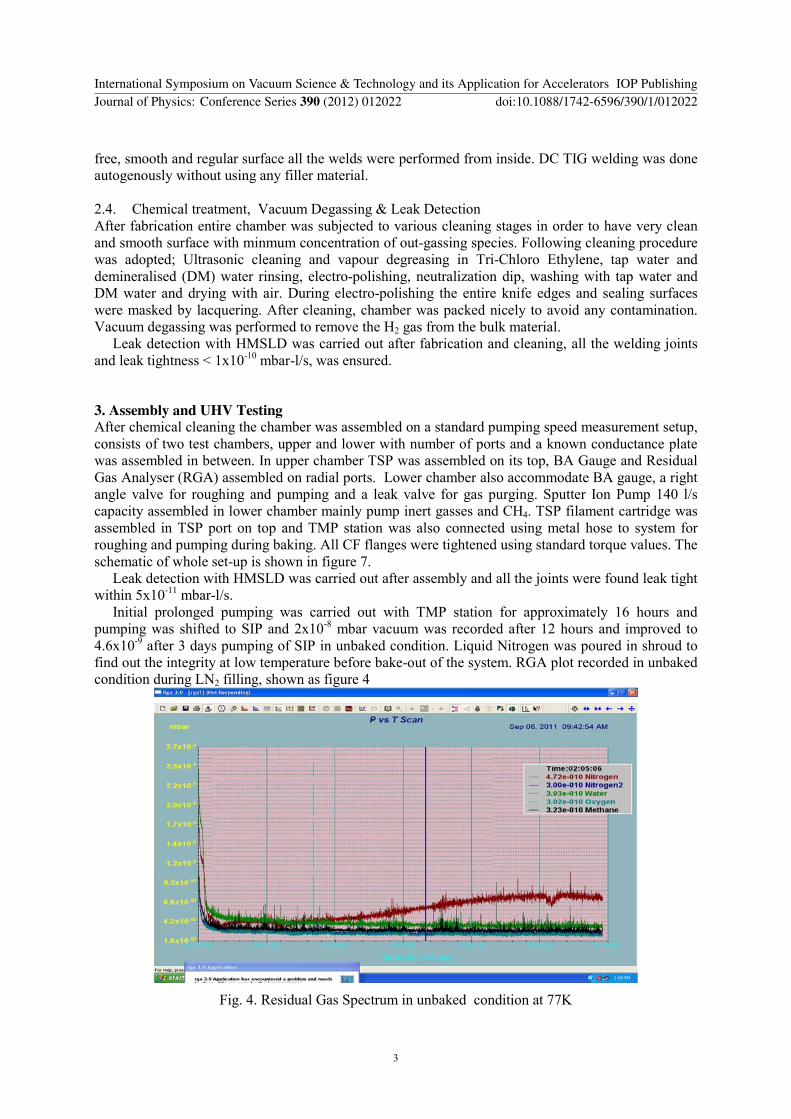
3 Assembly and UHV Testing After chemical cleaning the chamber was assembled on a standard pumping speed measurement setup consists of two test chambers upper and lower with number of ports and a known conductance plate was assembled in between In upper chamber TSP was assembled on its top BA Gauge and Residual Gas Analyser (RGA) assembled on radial ports Lower chamber also accommodate BA gauge a right angle valve for roughing and pumping and a leak valve for gas purging Sputter Ion Pump 140 ls capacity assembled in lower chamber mainly pump inert gasses and CH4 TSP filament cartridge was assembled in TSP port on top and TMP station was also connected using metal hose to system for roughing and pumping during baking All CF flanges were tightened using standard torque values The schematic of whole set-up is shown in figure 7 Leak detection with HMSLD was carried out after assembly and all the joints were found leak tight within 5x10-11 mbar-ls Initial prolonged pumping was carried out with TMP station for approximately 16 hours and pumping was shifted to SIP and 2x10⁻⁸ mbar vacuum was recorded after 12 hours and improved to 46x10-9 after 3 days pumping of SIP in unbaked condition Liquid Nitrogen was poured in shroud to find out the integrity at low temperature before bake-out of the system RGA plot recorded in unbaked condition during LN2 filling shown as figure 4
Fig 4 Residual Gas Spectrum in unbaked condition at 77K
International Symposium on Vacuum Science amp Technology and its Application for Accelerators IOP PublishingJournal of Physics Conference Series 390 (2012) 012022 doi1010881742-65963901012022
3
From the figure 4 it was evident that H2O was dominating gas followed by N2CO and O2 in unbaked condition and then LN2 was filled to see the performance of the shroud A sudden fall in H2O N2CO and O2 was observed as the shroud temperature reached 77K Entire set-up was baked at 250 ordmC for 48 hours and BA gauges RGA and TSP filaments were degassed properly at the end of baking cycle Ultimate vacuum was recorded after 24 hours pumping with only SIP One TSP filament was fired with 42 amps current with the help of power supply for two pulses of 1 min each with interval and 12 hrs delay time was set for next firing the ultimate vacuum was noted after 24 hrs pumping of TSP at 300K Simultaneously LN2 was poured into shroud and TSP was fired again ultimate vacuum noted after 24 hrs pumping Ultimate vacuum recorded with different pumping conditions are shown in table 1
Table-1
Pressure (mbar) Time duration Pump used Temp
15x10-10 24 hrs SIP only 300 K
73x10-11 24 hrs SIP + TSP 300 K
26x10-11 24 hrs SIP + TSP 77 K
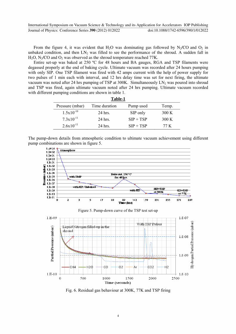
The pump-down details from atmospheric condition to ultimate vacuum achievement using different pump combinations are shown in figure 5
Figure 5 Pump-down curve of the TSP test set-up
Fig 6 Residual gas behaviour at 300K 77K and TSP firing
International Symposium on Vacuum Science amp Technology and its Application for Accelerators IOP PublishingJournal of Physics Conference Series 390 (2012) 012022 doi1010881742-65963901012022
4
At 77 K temperature it was observed that partial pressure of H2O CO CO2 CH4 and O2 fall immediately and there was delay observed in H2 gas on cool surface The TSP was fired once to see the release of gasses from the filament except H2 no other gases were released The ultimate vacuum achieved was 7x10-11 mbar with-out RGA and the ultimate vacuum was limited to 5x10⁻¹⁰ mbar with RGA filament on RGA plot was shown in figure 6
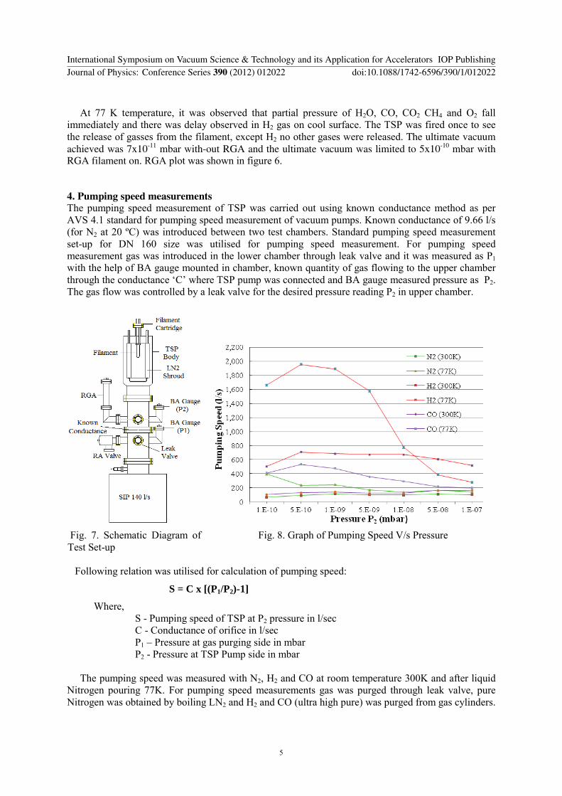
4 Pumping speed measurements The pumping speed measurement of TSP was carried out using known conductance method as per AVS 41 standard for pumping speed measurement of vacuum pumps Known conductance of 966 ls (for N2 at 20 ordmC) was introduced between two test chambers Standard pumping speed measurement set-up for DN 160 size was utilised for pumping speed measurement For pumping speed measurement gas was introduced in the lower chamber through leak valve and it was measured as P1 with the help of BA gauge mounted in chamber known quantity of gas flowing to the upper chamber through the conductance lsquoCrsquo where TSP pump was connected and BA gauge measured pressure as P2 The gas flow was controlled by a leak valve for the desired pressure reading P2 in upper chamber
Fig 7 Schematic Diagram of Test Set-up
Fig 8 Graph of Pumping Speed Vs Pressure
Following relation was utilised for calculation of pumping speed
S = C x [(P1P2)-1]
Where S - Pumping speed of TSP at P2 pressure in lsec C - Conductance of orifice in lsec P1 ndash Pressure at gas purging side in mbar P2 - Pressure at TSP Pump side in mbar The pumping speed was measured with N2 H2 and CO at room temperature 300K and after liquid Nitrogen pouring 77K For pumping speed measurements gas was purged through leak valve pure Nitrogen was obtained by boiling LN2 and H2 and CO (ultra high pure) was purged from gas cylinders
International Symposium on Vacuum Science amp Technology and its Application for Accelerators IOP PublishingJournal of Physics Conference Series 390 (2012) 012022 doi1010881742-65963901012022
5
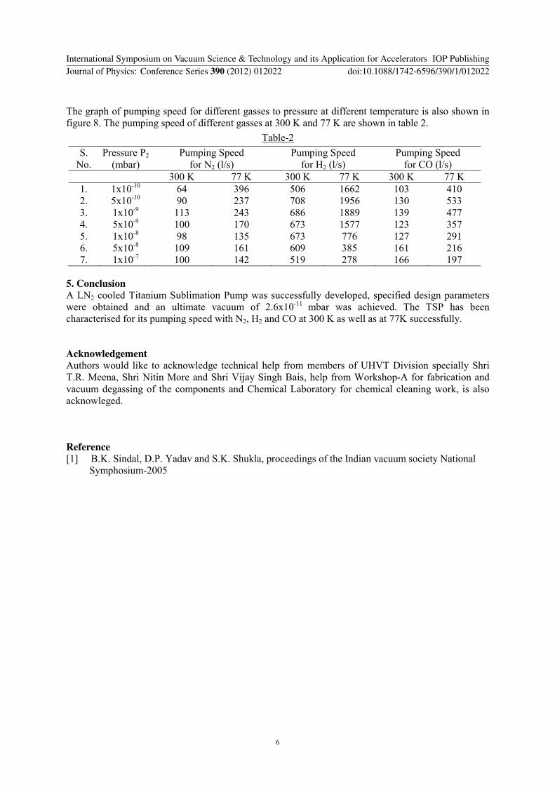
The graph of pumping speed for different gasses to pressure at different temperature is also shown in figure 8 The pumping speed of different gasses at 300 K and 77 K are shown in table 2
Table-2
S No
Pressure P2 (mbar)
Pumping Speed for N2 (ls)
Pumping Speed for H2 (ls)
Pumping Speed for CO (ls)
300 K 77 K 300 K 77 K 300 K 77 K 1 1x10⁻¹⁰ 64 396 506 1662 103 410 2 5x10⁻¹⁰ 90 237 708 1956 130 533 3 1x10⁻⁹ 113 243 686 1889 139 477 4 5x10⁻⁹ 100 170 673 1577 123 357 5 1x10⁻⁸ 98 135 673 776 127 291 6 5x10⁻⁸ 109 161 609 385 161 216 7 1x10⁻⁷ 100 142 519 278 166 197
5 Conclusion A LN2 cooled Titanium Sublimation Pump was successfully developed specified design parameters were obtained and an ultimate vacuum of 26x10-11 mbar was achieved The TSP has been characterised for its pumping speed with N2 H2 and CO at 300 K as well as at 77K successfully
Acknowledgement Authors would like to acknowledge technical help from members of UHVT Division specially Shri TR Meena Shri Nitin More and Shri Vijay Singh Bais help from Workshop-A for fabrication and vacuum degassing of the components and Chemical Laboratory for chemical cleaning work is also acknowleged
Reference [1] BK Sindal DP Yadav and SK Shukla proceedings of the Indian vacuum society National Symphosium-2005
International Symposium on Vacuum Science amp Technology and its Application for Accelerators IOP PublishingJournal of Physics Conference Series 390 (2012) 012022 doi1010881742-65963901012022
6
Development and UHV testing of LN2 cooled Titanium Sublimation Pump
B K Sindal1 K V A N P S Kumar Tripti Bansod and S K Shukla
Ultra High Vacuum Technology Division RRCAT Indore - 452 013
E-mail bksindalrrcatgovin
Abstract Titanium sublimation pumps (TSP) provide inexpensive large pumping speeds for active gases especially in UHV environment where residual gases are mainly H2 and CO etc The pumping speed of TSP is independent of pressure in this range Sublimation of Ti on liquid nitrogen (LN2) cooled surfaces is expected to provide large porosity in deposited film and this may also result in further enhancement of its pumping speed Accordingly a liquid nitrogen cooled TSP was developed to achieve clean vacuum in 10-11 mbar range in combination of sputter ion pump which is mainly used to take care of inert gas load The LN2 shroud was designed to have 19 litre capacity and offered approximately 2000 cm2 cooled surface area with approximately 250cm2 area coated with titanium film This paper describes the performance of the TSP at room temperature as well as after cooling with LN2 Quadrupole mass analyzer was utilized to analyze residual gases Simultaneously for pumping speed measurements for different gasses a setup with known conductance was also appended
1 Introduction Titanium Sublimation Pumps (TSP) are mostly used to supplement the pumping of Sputter Ion Pumps They have low cost simple operation and provide very high pumping speed for active gases in UHV region We have used commercially available lsquoUrsquo shaped filaments made of Titanium-Molybdenum alloy (85+15) of Oslash21 mm and having 35 mΩ resistance Three filaments mounted on simple four pin low electrical resistance feed-through with the help of SS connectors (Figure 2) A high current passed through the filaments by a power supply causing its temperature to rise sufficiently and sublimate titanium from filament This sublimated titanium then gets coat the on wall of the vacuum chamber the film reacts with gas molecules within the system to form low vapour pressure compounds The saturation time of film depends upon pressure and types of gasses pumped The pumping efficiency of TSP increased many times by cooling of coated wall to liquid nitrogen temperature due to increase in sticking coefficient for gases on cooled surfaces especially for H2 which shows highest partial pressure in UHV region This paper describes the development works and pumping speed measurement for different gases (N2 H2 amp CO) at various pressures and at 300K as well as 77K
2 Development of UHV chambers
21 Design Titanium sublimation Pump body
International Symposium on Vacuum Science amp Technology and its Application for Accelerators IOP PublishingJournal of Physics Conference Series 390 (2012) 012022 doi1010881742-65963901012022
Published under licence by IOP Publishing Ltd 1
Design of the vacuum chamber is governed by features like Geometry optimization material selection design for mechanical strength against various loadings like atmospheric pressure gasket sealing load and dead weight bakeability minimum gas load and maximum effective pumping speed available at pumping port TSP chamber is a triple layer vertically mounted cylindrical chamber with flat top having a port of size DN 40 Con-flat flange for mounting of TSP filament cartridge and two tubes of Oslash12mm for liquid nitrogen filling The torispherical bottom having port of DN 160 Con-flat flange was used for connection with vacuum system Overall dimensions of the vacuum chamber are Oslash203mm OD X 525 mm height Schematic orthographic front X-sectional view is shown in figure 3
The cylindrical shape for main shell was chosen to reduce wall thickness Similarly bottom was
having torispherical head because of higher strength-to-weight ratio facilitating light weight compared to flat plate construction The design of main shell and torispherical head was based on the guidelines of ASME section-VIII Div-I code Optimization of their thickness was based on stability against elastic buckling due to external atmospheric pressure of 15 PSI Iterative process floowed to arrive at minimum required thickness for this loading using rules under subsection UG-28(C) and UHA-28 part-D for SS 304L 10 torispherical head was designed for ease in fabrication Nominal thickness of 2 mm was selected for fabrication of outer pump body and 16 mm for liquid nitrogen shroud material of construction was SS 3034L Standard CF flange made by SS 316-L were used
22 Design of Titanium Sublimation Pump TSP with Liquid Nitrogen (LN2) shroud was developed which provides approx 2000 cm2 cooled surface area with approx 250 cm2 Titanium film quoted area for pumping at 300K as well as 77K 23 Fabrication The main shell was made from 2mm thick seam welded pipe of Oslash203 OD and 10 torispherical dished end both were readily available which was made as per the guidelines of ASME Section IX Standard available pipes were used to make liquid nitrogen shroud All the pipes were faced with high precision lathe and ports opening were also machined in dished ends standard CF flanges were machined on high precision lathe and boring operation was performed accordingly to accommodate pipe size Prior to welding all the joints were degreased and cleaned properly In order to give oxide
Fig 1 Photograph of TSP Fig 2 Filament cartridge of TSP
Fig 3 Schematic front X- sectional view
International Symposium on Vacuum Science amp Technology and its Application for Accelerators IOP PublishingJournal of Physics Conference Series 390 (2012) 012022 doi1010881742-65963901012022
2
free smooth and regular surface all the welds were performed from inside DC TIG welding was done autogenously without using any filler material 24 Chemical treatment Vacuum Degassing amp Leak Detection After fabrication entire chamber was subjected to various cleaning stages in order to have very clean and smooth surface with minmum concentration of out-gassing species Following cleaning procedure was adopted Ultrasonic cleaning and vapour degreasing in Tri-Chloro Ethylene tap water and demineralised (DM) water rinsing electro-polishing neutralization dip washing with tap water and DM water and drying with air During electro-polishing the entire knife edges and sealing surfaces were masked by lacquering After cleaning chamber was packed nicely to avoid any contamination Vacuum degassing was performed to remove the H2 gas from the bulk material Leak detection with HMSLD was carried out after fabrication and cleaning all the welding joints and leak tightness lt 1x10⁻¹⁰ mbar-ls was ensured
3 Assembly and UHV Testing After chemical cleaning the chamber was assembled on a standard pumping speed measurement setup consists of two test chambers upper and lower with number of ports and a known conductance plate was assembled in between In upper chamber TSP was assembled on its top BA Gauge and Residual Gas Analyser (RGA) assembled on radial ports Lower chamber also accommodate BA gauge a right angle valve for roughing and pumping and a leak valve for gas purging Sputter Ion Pump 140 ls capacity assembled in lower chamber mainly pump inert gasses and CH4 TSP filament cartridge was assembled in TSP port on top and TMP station was also connected using metal hose to system for roughing and pumping during baking All CF flanges were tightened using standard torque values The schematic of whole set-up is shown in figure 7 Leak detection with HMSLD was carried out after assembly and all the joints were found leak tight within 5x10-11 mbar-ls Initial prolonged pumping was carried out with TMP station for approximately 16 hours and pumping was shifted to SIP and 2x10⁻⁸ mbar vacuum was recorded after 12 hours and improved to 46x10-9 after 3 days pumping of SIP in unbaked condition Liquid Nitrogen was poured in shroud to find out the integrity at low temperature before bake-out of the system RGA plot recorded in unbaked condition during LN2 filling shown as figure 4
Fig 4 Residual Gas Spectrum in unbaked condition at 77K
International Symposium on Vacuum Science amp Technology and its Application for Accelerators IOP PublishingJournal of Physics Conference Series 390 (2012) 012022 doi1010881742-65963901012022
3
From the figure 4 it was evident that H2O was dominating gas followed by N2CO and O2 in unbaked condition and then LN2 was filled to see the performance of the shroud A sudden fall in H2O N2CO and O2 was observed as the shroud temperature reached 77K Entire set-up was baked at 250 ordmC for 48 hours and BA gauges RGA and TSP filaments were degassed properly at the end of baking cycle Ultimate vacuum was recorded after 24 hours pumping with only SIP One TSP filament was fired with 42 amps current with the help of power supply for two pulses of 1 min each with interval and 12 hrs delay time was set for next firing the ultimate vacuum was noted after 24 hrs pumping of TSP at 300K Simultaneously LN2 was poured into shroud and TSP was fired again ultimate vacuum noted after 24 hrs pumping Ultimate vacuum recorded with different pumping conditions are shown in table 1
Table-1
Pressure (mbar) Time duration Pump used Temp
15x10-10 24 hrs SIP only 300 K
73x10-11 24 hrs SIP + TSP 300 K
26x10-11 24 hrs SIP + TSP 77 K
The pump-down details from atmospheric condition to ultimate vacuum achievement using different pump combinations are shown in figure 5
Figure 5 Pump-down curve of the TSP test set-up
Fig 6 Residual gas behaviour at 300K 77K and TSP firing
International Symposium on Vacuum Science amp Technology and its Application for Accelerators IOP PublishingJournal of Physics Conference Series 390 (2012) 012022 doi1010881742-65963901012022
4
At 77 K temperature it was observed that partial pressure of H2O CO CO2 CH4 and O2 fall immediately and there was delay observed in H2 gas on cool surface The TSP was fired once to see the release of gasses from the filament except H2 no other gases were released The ultimate vacuum achieved was 7x10-11 mbar with-out RGA and the ultimate vacuum was limited to 5x10⁻¹⁰ mbar with RGA filament on RGA plot was shown in figure 6
4 Pumping speed measurements The pumping speed measurement of TSP was carried out using known conductance method as per AVS 41 standard for pumping speed measurement of vacuum pumps Known conductance of 966 ls (for N2 at 20 ordmC) was introduced between two test chambers Standard pumping speed measurement set-up for DN 160 size was utilised for pumping speed measurement For pumping speed measurement gas was introduced in the lower chamber through leak valve and it was measured as P1 with the help of BA gauge mounted in chamber known quantity of gas flowing to the upper chamber through the conductance lsquoCrsquo where TSP pump was connected and BA gauge measured pressure as P2 The gas flow was controlled by a leak valve for the desired pressure reading P2 in upper chamber
Fig 7 Schematic Diagram of Test Set-up
Fig 8 Graph of Pumping Speed Vs Pressure
Following relation was utilised for calculation of pumping speed
S = C x [(P1P2)-1]
Where S - Pumping speed of TSP at P2 pressure in lsec C - Conductance of orifice in lsec P1 ndash Pressure at gas purging side in mbar P2 - Pressure at TSP Pump side in mbar The pumping speed was measured with N2 H2 and CO at room temperature 300K and after liquid Nitrogen pouring 77K For pumping speed measurements gas was purged through leak valve pure Nitrogen was obtained by boiling LN2 and H2 and CO (ultra high pure) was purged from gas cylinders
International Symposium on Vacuum Science amp Technology and its Application for Accelerators IOP PublishingJournal of Physics Conference Series 390 (2012) 012022 doi1010881742-65963901012022
5
The graph of pumping speed for different gasses to pressure at different temperature is also shown in figure 8 The pumping speed of different gasses at 300 K and 77 K are shown in table 2
Table-2
S No
Pressure P2 (mbar)
Pumping Speed for N2 (ls)
Pumping Speed for H2 (ls)
Pumping Speed for CO (ls)
300 K 77 K 300 K 77 K 300 K 77 K 1 1x10⁻¹⁰ 64 396 506 1662 103 410 2 5x10⁻¹⁰ 90 237 708 1956 130 533 3 1x10⁻⁹ 113 243 686 1889 139 477 4 5x10⁻⁹ 100 170 673 1577 123 357 5 1x10⁻⁸ 98 135 673 776 127 291 6 5x10⁻⁸ 109 161 609 385 161 216 7 1x10⁻⁷ 100 142 519 278 166 197
5 Conclusion A LN2 cooled Titanium Sublimation Pump was successfully developed specified design parameters were obtained and an ultimate vacuum of 26x10-11 mbar was achieved The TSP has been characterised for its pumping speed with N2 H2 and CO at 300 K as well as at 77K successfully
Acknowledgement Authors would like to acknowledge technical help from members of UHVT Division specially Shri TR Meena Shri Nitin More and Shri Vijay Singh Bais help from Workshop-A for fabrication and vacuum degassing of the components and Chemical Laboratory for chemical cleaning work is also acknowleged
Reference [1] BK Sindal DP Yadav and SK Shukla proceedings of the Indian vacuum society National Symphosium-2005
International Symposium on Vacuum Science amp Technology and its Application for Accelerators IOP PublishingJournal of Physics Conference Series 390 (2012) 012022 doi1010881742-65963901012022
6