Embed Size (px)
Citation preview
Development of a Passive Magnetic Bearing System for a Flywheel
Energy Storage
Chan Ham
Mechatronics Engineering, Southern Polytechnic State University, Marietta, Georgia 30060, USA
Matthew Burton and Kurt Lin
Dept.of Mechanical, Materials, and Aerospace, University of Central Florida, Orlando, Florida 32816, USA
Young Hoon Joo
Corresponding author, Kunsan Nat’l University, Kunsan, Jeonbuk, Korea
Abstract: Magnetic bearings are an attractive alternative to mechanical bearings in flywheel energy storage systems
since they greatly reduce friction and wear. However, new problems are introduced in terms of stabilization;
particularly the magnetic bearing must provide enough damping to reduce excessive vibrations. Two novel
configurations of passive magnetic bearings are introduced to meet system requirements. The first configuration,
utilizing two Halbach arrays, is proposed to introduce a levitating force as well as lateral stability. The second
configuration uses a null-flux coil passive magnet array to add lateral stability. This paper will focus on lateral
stability. Displacements in the lateral direction will result in a correction of rotor motion based on its velocity. In this
work, firstly the configuration of the Halbach and null-flux coil arrays is presented. Finite element models are then
developed for both cases to investigate the resulting magnetic field, its reaction to rotor velocity, and its effects on
the system. As a result, it shows the effectiveness of the proposed configuration to stabilize the lateral dynamics of a
flywheel energy storage system.
1. Introduction
It has been proposed that a flywheel energy storage
system could be implemented to capture and store the
energy captured from diverse energy production
systems until it is needed. Later it can be converted
into electrical energy. However, a major issue with
this approach is the friction caused by traditional ball
bearings as well as any potential support system for
the flywheel. This friction will remove energy from
the system, and in most cases will need to be greatly
reduced for the system to function efficiently. To this
end, magnetic bearings have been proposed as an
alternative method of stabilizing and supporting the
flywheel system. Magnetic bearings are placed either
on the rotor or the stator with matching permanent
magnets to produce a force.
Due to the dynamics of the system, the
magnetic field being produced will experience
motion relative to the permanent magnet. This results
in eddy currents being created and dissipated; the
force produced is a damping force proportional to the
velocity of the change in magnetic flux. Hence, the
resultant force will depend on both the position and
velocity of the rotor. (Sze Kwan Cheah, 2008)
This paper will focus on the use of passive
magnetic bearings (PMB) in this application. Though
rotor motion cannot be corrected as accurately, PMB
do not have to be controlled; thus, they consume less
power.
In this paper, two magnetic bearing
configurations are presented for use in a flywheel
energy storage system. The first PMB configuration
is composed of two Halbach arrays. These arrays can
be used for stabilization as well as levitation of a
vertical flywheel with coils placed on the perimeter
and underneath the PMB. It has been shown in
previous research that the magnetic field is
concentrated on one side of the array and canceled on
the other (Thompson W. K., 2006). This leads to the
attractive motion correcting and levitation forces
required in this system. In this paper, only the forces
contributing to torsional damping and lateral motion
correction will be discussed.
The second configuration proposed is a null-
flux coil array. A null-flux coil uses two juxtaposed
magnets with opposite coil windings to produce a
magnetic field. Due to eddy current effects a small
permanent magnet moving over the PMB will
experience a correction in its motion to the center of
the two magnets. This will result in the lateral
correction of motion in a flywheel rotor. Damping
forces are also produced in the torsional direction, but
these will not be investigated.
Once the configuration is fully described
and the mathematics is rigorously defined the
magnetic fields resulting from these PMB
configurations will be modeled. For the Halbach
configuration, the damping due to torsional velocity
will be discussed as well as forces correcting its
lateral motion. These results will be compared for
various rotor velocities. For the null-flux coil array,
only lateral correcting forces will be discussed.
Some assumptions must be made about the
system to ensure accurate results. Neither torsional
stability nor angular displacement will be considered
in this paper to simplify analysis. The magnetic field
results will also be limited to a 2-D plane. With more
advanced work in this field these assumptions may be
reconsidered and hence more in depth analysis could
be performed to investigate the effects of Halbach
and null-flux coil arrays in flywheel suspension.
2. System and Configuration
Halbach Array
For the system under consideration, a flywheel rotor
will be positioned vertically. As it spins along its
axis, several stability issues need to be explored. The
rotor will need to be suspended against the force of
gravity acting downward. This issue hopes to be
solved by the use of the Halbach array; it will be
attached to the bottom of the rotor. The magnetic
field produced by the Halbach array will act against
coils wound vertically. According to the following
equation, this should result in a force counteracting
gravity. More specifically, this force is given by a
pressure over the surface area of the rotor. In the
equation below, �� denotes the permeability of a
vacuum, which is a constant. ���� denotes the
magnetic levitation pressure. B is the value of the
magnetic field. It is this value that is to be
investigated and determined in this paper.
���� �
�� (1)
It should be noted that this repelling force is
due to the most attractive feature of the Halbach
array: the magnetic field will be concentrated on the
bottom of the array while canceled on the top. While
this phenomenon will has been explained, it will not
be investigated analytically due to simulation
limitations.
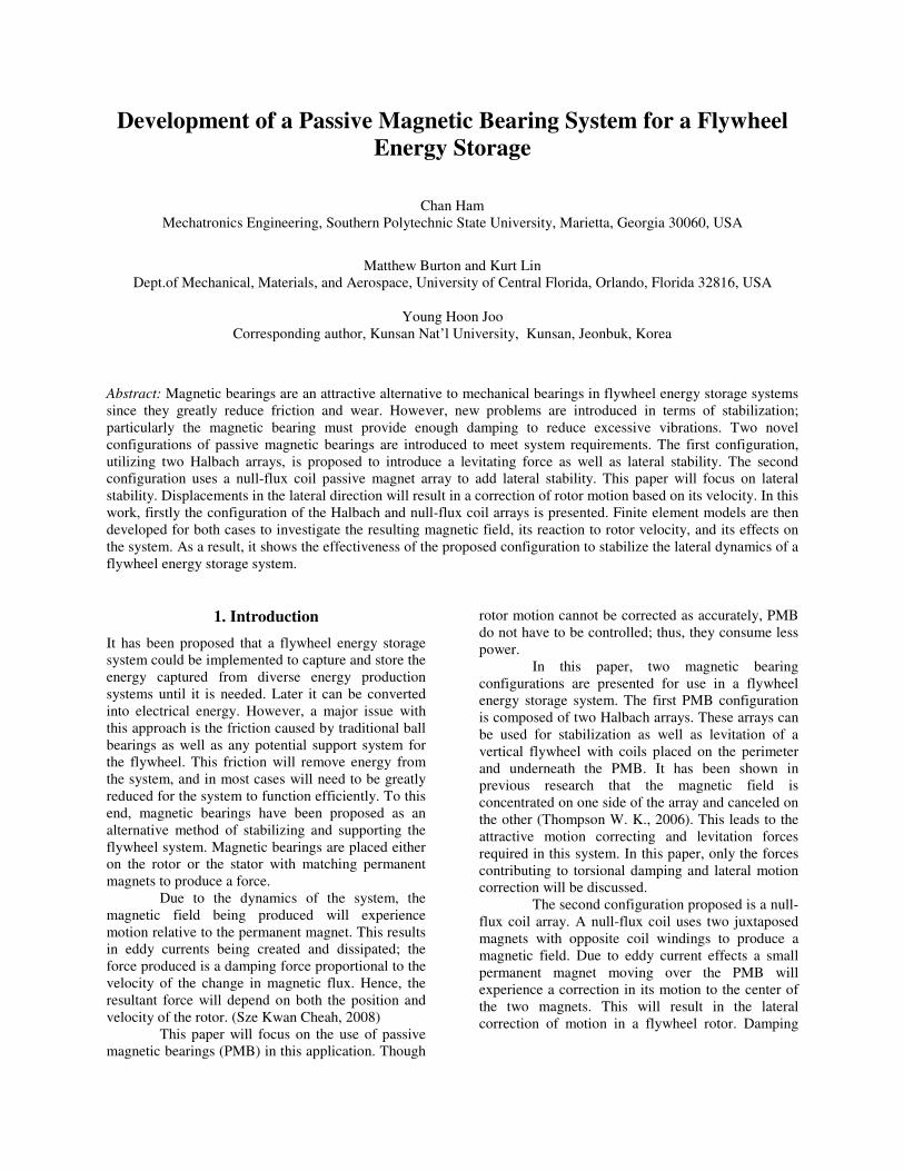
The system described in this paper involves
two concentric Halbach arrays with similar
magnetization patterns. The first array is located on
the end of the rotor, with the rotor occupying the
center. The second Halbach array can be seen on the
stator surrounding the rotor. It is believed that the
interaction of these two arrays will result in a
horizontal restoring force as well as damping forces
that should be confirmed by analysis.
Figure 1. Double Halbach Array Configuration.
The effects of the Halbach configuration
producing a restoring force in the radial direction are
of the most importance. To describe the force
produced by a current and magnetic field, the simple
equation below is used.
�� � � ��� (2)
Now an expression must be found for the
magnetic field. The following equation describes the
magnetic field in terms of a differential element of
the field. For a circular ring magnet, the magnetic
flux density B has the differential equation below,
where permeability and magnetization per unit length
are given by �� and ��respectively (Cheng, 1992).
� � � � �� �
�������|!"|#
��� (3)
where R is a position vector describing the position
of the magnet in question. dI is a length vector
describing a differential element of length along the
magnet (Cheng, 1992).
�� � $% sin ) �)* + % cos ) �). (4)
The drag force produced by Lorentz effects
needs to be described. It can be shown that this force,
which is dependent on velocity, is given by the
following equation. /0 gives the field in the center of
the coil wire, 10 is the number of coil turns, L is the
inductance, R is the resistance, and 2� is the
excitation frequency of the circuit (Han, 2000).
�� � 3456
�!75
893:; <
=>
(5)
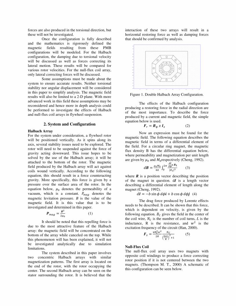
Null-Flux Coil
The null-flux coil array uses two magnets with
opposite coil windings to produce a force correcting
rotor position if it is not centered between the two
magnets. (Thompson M. T., 2000) A schematic of
this configuration can be seen below.
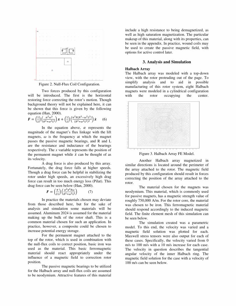
Figure 2. Null-Flux Coil Configuration.
Two forces produced by this configuration
will be introduced. The first is the horizontal
restoring force correcting the rotor’s motion. Though
background theory will not be explained here, it can
be shown that this force is given by the following
equation (Han, 2000).
� � 8>�< 8 ?@
!=@A< B + 8>�< 8?!C!D@AE
C!=@AE < BF (6)
In the equation above, G represents the
magnitude of the magnet’s flux linkage with the lift
magnets, H is the frequency at which the magnet
passes the passive magnetic bearings, and R and L
are the resistance and inductance of the bearings
respectively. The x variable represents the position of
the permanent magnet while �F can be thought of as
its velocity.
A drag force is also produced by this array.
Fortunately, the drag force falls at higher speeds.
Though a drag force can be helpful in stabilizing the
rotor under high speeds, an excessively high drag
force can result in too much energy loss (Pilat). This
drag force can be seen below (Han, 2000).
� � 8 ��>< 8 ?B!@
!=@A< (7)
In practice the materials chosen may deviate
from those described here, but for the sake of
analysis and simulation some materials will be
assumed. Aluminum 2024 is assumed for the material
making up the bulk of the rotor shaft. This is a
common material chosen for such an application. In
practice, however, a composite could be chosen to
increase potential energy storage.
For the permanent magnet attached to the
top of the rotor, which is used in combination with
the null-flux coils to correct position, basic iron was
used as the material. This basic ferromagnetic
material should react appropriately under the
influence of a magnetic field to correction rotor
position.
The passive magnetic bearings to be utilized
for the Halbach array and null-flux coils are assumed
to be neodymium. Attractive features of this material
include a high resistance to being demagnetized, as
well as high saturation magnetization. The particular
makeup of this material, along with its properties, can
be seen in the appendix. In practice, wound coils may
be used to create the passive magnetic field, with
options for active control later.
3. Analysis and Simulation
Halbach Array
The Halbach array was modeled with a top-down
view, with the rotor protruding out of the page. To
simplify analysis and to aid in possible
manufacturing of this rotor system, eight Halbach
magnets were modeled in a cylindrical configuration
with the rotor occupying the center.
Figure 3. Halbach Array FE Model.
Another Halbach array magnetized in
similar directions is located around the perimeter of
the array attached to the rotor. The magnetic field
produced by this configuration should result in forces
correcting the position of the array attached to the
rotor.
The material chosen for the magnets was
neodymium. This material, which is commonly used
for passive magnets, has a magnetic strength value of
roughly 750,000 A/m. For the rotor core, the material
was chosen to be iron. This ferromagnetic material
should respond accordingly to the induced magnetic
field. The finite element mesh of this simulation can
be seen below.
The simulation created was a parametric
model. To this end, the velocity was varied and a
magnetic field solution was plotted for each.
Maxwell stress tensors were also output for each of
these cases. Specifically, the velocity varied from 0
m/s to 100 m/s with a 10 m/s increase for each case.
The velocity in question describes the tangential
angular velocity of the inner Halbach ring. The
magnetic field solution for the case with a velocity of
100 m/s can be seen below.
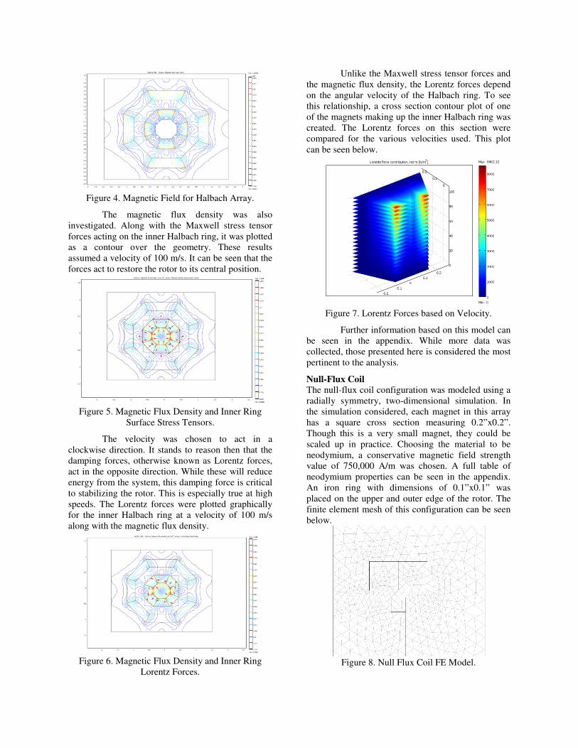
Figure 4. Magnetic Field for Halbach Array.
The magnetic flux density was also
investigated. Along with the Maxwell stress tensor
forces acting on the inner Halbach ring, it was plotted
as a contour over the geometry. These results
assumed a velocity of 100 m/s. It can be seen that the
forces act to restore the rotor to its central position.
Figure 5. Magnetic Flux Density and Inner Ring
Surface Stress Tensors.
The velocity was chosen to act in a
clockwise direction. It stands to reason then that the
damping forces, otherwise known as Lorentz forces,
act in the opposite direction. While these will reduce
energy from the system, this damping force is critical
to stabilizing the rotor. This is especially true at high
speeds. The Lorentz forces were plotted graphically
for the inner Halbach ring at a velocity of 100 m/s
along with the magnetic flux density.
Figure 6. Magnetic Flux Density and Inner Ring
Lorentz Forces.
Unlike the Maxwell stress tensor forces and
the magnetic flux density, the Lorentz forces depend
on the angular velocity of the Halbach ring. To see
this relationship, a cross section contour plot of one
of the magnets making up the inner Halbach ring was
created. The Lorentz forces on this section were
compared for the various velocities used. This plot
can be seen below.
Figure 7. Lorentz Forces based on Velocity.
Further information based on this model can
be seen in the appendix. While more data was
collected, those presented here is considered the most
pertinent to the analysis.
Null-Flux Coil
The null-flux coil configuration was modeled using a
radially symmetry, two-dimensional simulation. In
the simulation considered, each magnet in this array
has a square cross section measuring 0.2”x0.2”.
Though this is a very small magnet, they could be
scaled up in practice. Choosing the material to be
neodymium, a conservative magnetic field strength
value of 750,000 A/m was chosen. A full table of
neodymium properties can be seen in the appendix.
An iron ring with dimensions of 0.1”x0.1” was
placed on the upper and outer edge of the rotor. The
finite element mesh of this configuration can be seen
below.
Figure 8. Null Flux Coil FE Model.
In the finite element mesh above, the dark
lines represent boundary surfaces while the gray lines
represent meshing elements. For this simulation,
parabolic triangular elements were used.
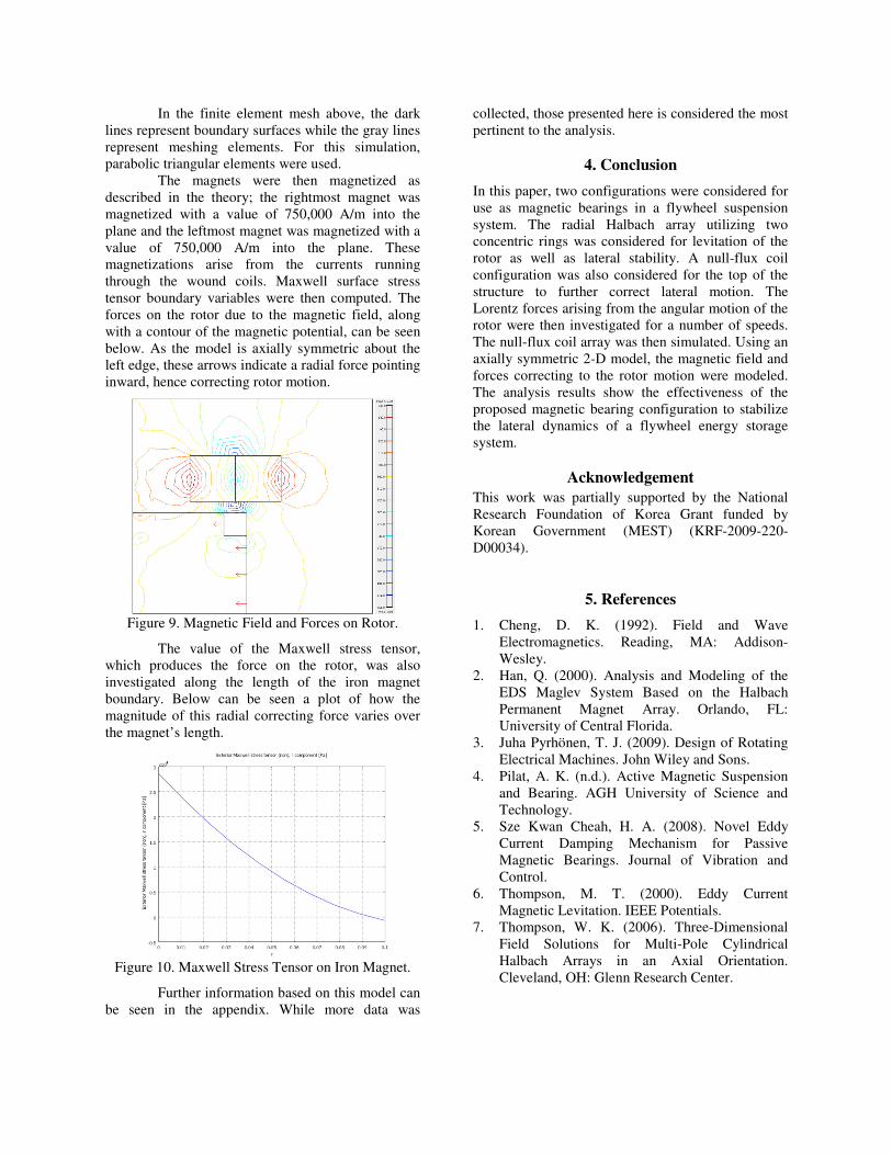
The magnets were then magnetized as
described in the theory; the rightmost magnet was
magnetized with a value of 750,000 A/m into the
plane and the leftmost magnet was magnetized with a
value of 750,000 A/m into the plane. These
magnetizations arise from the currents running
through the wound coils. Maxwell surface stress
tensor boundary variables were then computed. The
forces on the rotor due to the magnetic field, along
with a contour of the magnetic potential, can be seen
below. As the model is axially symmetric about the
left edge, these arrows indicate a radial force pointing
inward, hence correcting rotor motion.
Figure 9. Magnetic Field and Forces on Rotor.
The value of the Maxwell stress tensor,
which produces the force on the rotor, was also
investigated along the length of the iron magnet
boundary. Below can be seen a plot of how the
magnitude of this radial correcting force varies over
the magnet’s length.
Figure 10. Maxwell Stress Tensor on Iron Magnet.
Further information based on this model can
be seen in the appendix. While more data was
collected, those presented here is considered the most
pertinent to the analysis.
4. Conclusion
In this paper, two configurations were considered for
use as magnetic bearings in a flywheel suspension
system. The radial Halbach array utilizing two
concentric rings was considered for levitation of the
rotor as well as lateral stability. A null-flux coil
configuration was also considered for the top of the
structure to further correct lateral motion. The
Lorentz forces arising from the angular motion of the
rotor were then investigated for a number of speeds.
The null-flux coil array was then simulated. Using an
axially symmetric 2-D model, the magnetic field and
forces correcting to the rotor motion were modeled.
The analysis results show the effectiveness of the
proposed magnetic bearing configuration to stabilize
the lateral dynamics of a flywheel energy storage
system.
Acknowledgement This work was partially supported by the National
Research Foundation of Korea Grant funded by
Korean Government (MEST) (KRF-2009-220-
D00034).
5. References
1. Cheng, D. K. (1992). Field and Wave
Electromagnetics. Reading, MA: Addison-
Wesley.
2. Han, Q. (2000). Analysis and Modeling of the
EDS Maglev System Based on the Halbach
Permanent Magnet Array. Orlando, FL:
University of Central Florida.
3. Juha Pyrhönen, T. J. (2009). Design of Rotating
Electrical Machines. John Wiley and Sons.
4. Pilat, A. K. (n.d.). Active Magnetic Suspension
and Bearing. AGH University of Science and
Technology.
5. Sze Kwan Cheah, H. A. (2008). Novel Eddy
Current Damping Mechanism for Passive
Magnetic Bearings. Journal of Vibration and
Control.
6. Thompson, M. T. (2000). Eddy Current
Magnetic Levitation. IEEE Potentials.
7. Thompson, W. K. (2006). Three-Dimensional
Field Solutions for Multi-Pole Cylindrical
Halbach Arrays in an Axial Orientation.
Cleveland, OH: Glenn Research Center.