Embed Size (px)
Citation preview

EIDGENÖSSISCHE TECHNISCHE HOCHSCHULE LAUSANNEPOLITECNICO FEDERALE LOSANNASWISS FEDERAL INSTITUTE OF TECHNOLOGY LAUSANNE
Faculty STI – Section of Microtechnology – Institute of MicrosystemsOctober 2001 to February 2002
RReeaalliissaattiioonn aanndd tteesstt ooff aa ppaassssiivvee mmaaggnneettiicc bbeeaarriinnggwwiitthh aann iinnhheerreenntt ppoowweerr ggeenneerraattoorr // sseennssoorr
SSeemmeessttee rr pprroojjeecctt
Marcel LeuteneggerSwiss Federal Institute of Technology Lausanne (EPFL), Switzerland, [email protected]
Ass. Jan SandtnerSwiss Federal Institute of Technology Lausanne (EPFL), Switzerland, [email protected]
Prof. Hannes BleulerSwiss Federal Institute of Technology Lausanne (EPFL), Switzerland, [email protected]

EIDGENÖSSISCHE TECHNISCHE HOCHSCHULE LAUSANNEPOLITECNICO FEDERALE LOSANNASWISS FEDERAL INSTITUTE OF TECHNOLOGY LAUSANNE
Faculty STI – Section of Microtechnology – Institute of MicrosystemsOctober 2001 to February 2002
AAbbssttrraaccttThe axial passive magnetic bearing comprises an inherent ironless permanent magnet power generator, a sim-
ple signal control unit and an electromagnetic actuator. The power generator comprises three coil systems – thefirst furnishes raw actuator power, the second senses axial position and the third supplies the signal control unit.The actuator was designed similar to a loudspeaker coil. It is located in the close vicinity of the power generator.Hence, the electrical energy does not need to be transported over long distances.
The bearing possesses load capacity and stiffness characteristics that can be similar to those of conventionalactive magnetic bearings but without the need of expensive and complicated sensors, power amplifiers and con-trol systems. It can be conceived for almost arbitrary available power and stiffness requirements. As long as therotor is in the axially centred position, very low losses are present. To achieve this goal, the present design doestake advantage of some few active electronic elements.
Therefore, the project result is a newly designed and build demonstrator. Its actuator was designed to supply asteady force of about 10N and peak forces of about 30N. By means of a simple analogous proportional–differen-tial regulator, an axial stiffness of about 1N/m·rpm was measured – giving 2kN/m to 25kN/m depending uponthe rotation speed. The use of a more sophisticated regulator will allow better actuator control and hereby pushstiffness above 100kN/m. In this case, of course, the actuator should be enforced to sink more power withoutoverheating.
Lausanne, February 8, 2002 The author:
Marcel Leutenegger
Acknowledgements for assistance to: Jan SandtnerProf. BleulerRoland Moser

TTaabbllee ooff ccoonntteennttssPPrroojjeecctt bbrriieeff 44
11.. IInnttrroodduuccttiioonn 55
22.. BBaassiicc ccoonncceepptt 662.1 Demonstrator layout 62.2 System stability 72.3 Application limits 7
33.. DDeessiiggnn 883.1 Power generator / sensor 83.2 Axial actuator 103.3 Mechanical design tips 123.4 Signal processing 133.5 Electrical design tips 15
44.. RReeaalliissaatt iioonn 11774.1 Problems during construction 174.2 Chosen regulator behaviour 17
55.. VVeerriiffiiccaatt iioonn 1188
66.. CCoonncclluussiioonn 1199

Lausanne, February 8, 2002
4 – 40
PPrroojjeecctt bbrriieeffThe axial passive magnetic bearing comprises an inherent ironless permanent magnet generator, which acts si-
multaneously as a position sensor. The energy coming from the generator is transferred via a small number ofsemiconductor diodes to an actuator, which is similar to those used in ordinary active magnetic bearings. Thestator contains three sets of air coils: main generator coils, sensor coils and compensating generator coils. Thegenerator coils are connected additionally thus producing a steady voltage independent of the rotor’s axial posi-tion. The sensor coils are connected differentially; the induced voltage depends strongly on the axial position,being zero when the rotor is exactly at the centred position. The third coil system serves as a compensation of asteady current, which would circulate even at the rotor’s centred position. As long as the rotor is at the centredposition, practically no losses are present. Stability is only achieved in the rotating state.
Theory: 30%
Praxis: 70%
Student:Marcel Leutenegger
Support:Ass. Jan Sandtner
[email protected] 693 59 43ME H0 539
Prof. Hannes [email protected] 693 59 27ME A3 494
Delays:Report
a hand out until 1700 on 8th February 2002 to Prof. Bleuler and Mr Sandtner
Presentation20´ presentation followed by 30´ discussionbegin at 1315 on 13th February 2002room ME A31 at campus

Lausanne, February 8, 2002
5 – 40
11.. IInnttrroodduuccttiioonn
Global implicationsRotating machines are indispensable elements of modern civilisation. In most of these machines, mechanical
bearings are used, involving lubrication, friction, wear and therefore a finite life. It would be very interesting if itwas possible to replace mechanical bearings by contactless ones. No contact means no mechanical friction, thusno lubrication and no mechanical wear. This makes maintenance-free long life bearings available.
At the moment, mainly two contactless bearing types are used:1. Gas bearings – often air bearings – providing astonishing high load capacities and stiffnesses. They are of
relatively simple mechanical construction. The gas film between the moving parts is either created by gasinjection using an external compressor or by an intermediate sheet providing a self-filling while parts aremoving.Their characteristics are influenced by gas pressure – especially if atmospheric air is used. Particularly, gasbearings are completely inapplicable in vacuum.Note that particles in the gap like dust can be abrasive, thus causing wear problems.
2. Active magnetic bearings achieving load capacities and stiffnesses of mechanical bearings at the price ofexpensive and complicated sensors, power amplifiers and control systems.They do not wear and they are nearly friction-free. If the energy needed for the electromagnetic actuatorscomes from an external source, energy losses of moving parts are almost zero. Nevertheless, total energyconsumption of magnetic bearings is rather greater than for competitive gas bearings. On the other hand,magnetic bearings work well in almost any environment.
Project circumstancesThis semester project is part of the development of a “flywheel” – a temporary energy storage system to re-
place electrochemical cells by a mass storing rotational kinetic energy. By using a flywheel instead of a lead ac-cumulator, it should be possible to i) double energy/mass ratio, ii) increase charge/discharge efficiency and iii)overcome the limited number of charge/discharge cycles. Plausible applications would be power supplies for sat-ellites or electromobiles where these characteristics are looked for.
If the flywheel’s rotational speed varies from 30% to 100% of its maximum speed, it enables discharge of up to90% of stored kinetic energy. Maximum speed would be about 250krpm – depending on materials and geometryused for the rotor. The rotor would be held in vacuum to eliminate gas friction. Its radial stability is achieved bya permanent magnet suspension causing no energy losses at all. Unfortunately, this permanent magnet suspen-sion introduces axial instability which cannot be compensated by another permanent magnet system. For mainte-nance-free systems, mechanical contact during rotation is prohibited. So a passive axial magnetic bearingoffering enough axial stiffness/force should do the job.
Project goalsRealisation of a demonstrator to test the concept mentioned by Jan Sandtner et al [1]. The demonstrator com-
prises i) a standard asynchronous motor supplying rotational kinetic energy, ii) an inherent ironless genera-tor/sensor creating the electrical power needed for iii) the axial electromagnetic actuator.
To prove feasibility of a flywheel mentioned above, it should be possible to measure restoring forces of theaxial actuator depending upon rotation speed and axis position. It was decided to use a mechanical bearing forradial stability – at the condition that this bearing does not provide any axial forces.
The demonstrator should work within 3krpm to 30krpm of rotor speed. This upper limit has been given by theused power supply / motor pair. It allows to use cheaper aluminium parts for the rotor assembly instead of highstrain materials and assures operator’s security while manipulating the system.
In the sense of a flywheel application, the axial magnetic bearing should work at minimum energy consump-tion. Especially, it should present no consumption as long as the rotor is in the axially centred position. Further-more, the generator and the actuator should not introduce radial instability. Note that the motor used for thisdemonstrator is not of the same type as it will be used for the flywheel, so there is no special constraint on it.
1 J. Sandtner, J. Bermudez, H. Bleuler, “High speed passive magnetic bearing with increased load supporting capabilities”
presented at the 7th International Symposium on Magnetic Bearings, August 23-25, 2000 at the Swiss Federal Institute ofTechnology Zurich (ETHZ) [consult annexe for a copy]

Lausanne, February 8, 2002
6 – 40
22.. BBaassiicc ccoonncceeppttPlease consult the article by Jan Sandtner et al [2] attached to the annexe. It describes a raw design to increase
radial stabilisation forces for a magnetically suspended rotor – a basic design for axial stabilisation will be de-duced from.
It is known that it is not possibleto maintain tridimensional stabilitywith a steady permanent magnetconfiguration. Thus, bidimensionalsuspension is easily obtained to theprice of inevitable instability in thethird dimension.
Therefore, different to the radialdesign, this demonstrator aims toset into practice an axial positionregulator as a source of axial rotorstability and not only as a load ca-pacity increment.
As the graph at the right shows,the actuator must provide higherrestoring forces than the radialmagnetic bearing compensates. Ifthe total force stays retroactive,there is a good chance to obtain astable rotor position.
z
Fz
Fz ≈ Fz' = FzoSIN(2πz/Tz)
Ftotal
Factuator
Graph 1: Axial force caused by a radial bearing comprising five con-secutive ring magnets on rotor as well as on stator.The period Tz is about two times the ring magnet thickness.For positions z∈[–20%,+20%]Tz, radial stability is main-tained.
22..11 DDeemmoonnssttrraattoorr llaayyoouuttThanks to a similar system
made by Jan Sandtner, the rawlayout has been given as shownat the right.
All the rotor as well as theirrespective stator parts are mo v-able parallel to the axis. Thisallows great flexibility to testseveral similar parts by simpleexchange.
Motor GeneratorSensor Actuator
Fact(position )
Figure 1: Coaxial arrangement of asynchronous motor, power genera-tor/ position sensor and electromagnetic actuator. The rotor iskept on axis by two radial magnetic bearings [3]. A simplesignal processing unit links generator and actuator.
Generator/sensorThe rotor assembly establishes a position and time dependent magnetic flux density. Time dependence is
given by the rotation, while position dependence has to be set up carefully. One idea is to fix several perma-nent magnet pairs onto two identical discs. Then, the discs are mounted in front of each other. This gives aposition dependent axial flux density between them [4].
The stator assembly contains several separated air coils. A number of coils are set up to give a nearly posi-tion independent AC voltage which can serve as a permanent current supply. Two other coil systems – oneon the left and one on the right – supply each a position dependent AC voltage. If the rotor moves to the left,the left coils has to increase their voltage while the right coils decrease their own one. So, an excursion of the
2 J. Sandtner, J. Bermudez, H. Bleuler, “High speed passive magnetic bearing with increased load supporting capabilities”
presented at the 7th International Symposium on Magnetic Bearings, August 23-25, 2000 at the Swiss Federal Institute ofTechnology Zurich (ETHZ) [consult annexe for a copy]
3 Replaced by mechanical bearings for this demonstrator. This allows measure of net actuator forces.4 Take care about eddy currents appearing in stator parts because they would brake down rotation speed. It is recom-
mended to restrain magnetic flux to the generator’s interior.

Lausanne, February 8, 2002
7 – 40
rotor causes a voltage difference to appear. This voltage difference indicates the actual rotor position and alsosupplies power to the actuator.
Signal processingThis unit conditions generator’s output power and trans-
fers it to the actuator. Usually, the actuator needs a DC cur-rent while the generator delivers an AC one. Therefore, itwill be necessary to control the sense of actuator’s currentdepending upon the rotor position.
The unit has to comprise as few electronic parts as possi-ble. At least, it should not rely on any active electronic de-vice. Thus, the electric schema at the right was proposed. Ituses only passive elements but lacks of steady actuator cur-rent because either the first or the second full wave rectifieris blocked.
Lleft Lright
Lactuator
Schema 1: Completely passive signal proc-essing
In fact, it requires supplies with current sinking capabilities.
ActuatorThe actuator is build of one or several coils. Either the coils attract to a ferromagnetic surface when a cur-
rent (AC or DC) flows through them or, if permanent magnets are used, the coil’s current (DC only) in thetransversally magnetic field will create a Lorenz force.
Having a dedicated actuator aims to improve the energy loss/force ratio. In this sense, permanent magnetsare a must. They enable a bi-directional configuration by means of one single coil. They also help save spaceand energy – the higher flux they offer, the better.
22..22 SSyysstteemm ssttaabbiilliittyyWith an electromagnetic actuator, a position x(t) has to be regulated to zero:The current Iact(t) is controlled. Flowing in a copper coil of the actuator, Iact(t) creates a linearly proportional
magnetic field which causes a linearly proportional force Fact(t)=C·Iact(t) to appear. Given Newton’s law, itsolves for Fact(t)=m·d2x(t)/dt2.
If a pure proportional regulator Iact(t)=Kp·x(t) is used, the system behaviour suites m·d2x(t)/dt2=C·Kp·x(t). Theresult of this homogenous differential equation is x(t)=A·cos(2π·t/T) with period T=2π·[m/(C·Kp)]0.5 and am-plitude A. There is a resonance at frequency fT=1/T, thus the system will be unstable if it is not introducedadditional damping.
Another approach uses a proportional-differential regulator giving Iact(t)=Kp·x(t)+Kd·dx(t)/dt. The proportionalterm serves to kill any steady state error and to counterbalance constant force perturbations. The differentialterm leads to an exponential behaviour x(t)≈A·e–k·t of the system and damps it. Fortunately – because dampingis done by the regulator – it will not necessarily cause additional energy losses.
A more careful study of system behaviour leads to an optimised regulator frequency response of the formK(f)=Kp·(1+j·f/fz)/(1+j·f/fp) with 0.3fp≈fb≈3fz where fb is the bandpass frequency for unitary gain of the sys-tem’s open loop transfer function X(f)·K(f). This regulator type better suppresses steady state errors and highfrequency modes.
Note that the above considerations only applies if Fact depends exclusively on Iact.
22..33 AApppplliiccaattiioonn lliimmiittssFor proper contactless function, the generator/actuator pair has to overcome the axial destabilising effect of
the radial permanent magnetic suspensions. This condition imposes that the generator/actuator pair provideshigher stiffness than the suspensions compensate.
Thus, in a limited axial range, the rotor’s position can be regulated. Out of this interval, the rotor’s positioncannot be kept stable – the bearing’s permanent magnets would attract each other establishing mechanicalcontact. Therefore, it is a good idea to impose mechanical emergency bearings keeping the rotor in a save po-sition range.

Lausanne, February 8, 2002
8 – 40
33.. DDeessiiggnn
33..11 PPoowweerr ggeenneerraattoorr // sseennssoorrThe basic idea was to use two planar slices equipped with perma-
nent magnets face to face. In the space between the slices, an axiallyvariable magnetic field is established. A coil placed somewhere inthis field produces a periodic voltage with variable amplitude de-pending upon axial position and rotation speed.
A planar multipolar Halbach arrangement of the permanent mag-nets has been tested earlier. To simplify the construction – and alsoto test another configuration – it was replaced by a planar multipolarfield shielded externally by ferromagnetic rings.
Figure 2 shows the retained design for the generator discs. Theirinterior will be equipped with several coil pairs – one coil at leftside, one at the right. A coil pair connected in differential mode cre-ates a voltage proportional to the excursion of the rotor, while addi-tionally connected coil pairs return a nearly position independentvoltage.
It is possible to put the permanent magnets in two configurations –either the magnets pull or push their opposite neighbours. If theypush their neighbours, they are in the repulsive mode, otherwise inthe attractive mode.
Figure 2: Basic generator design.
GeometryThe external diameter of the generator has been fixed to 115mm [5]. While the axle diameter was given by
other existing systems, the generator’s axial position has to be adjustable. So a fixation by means of a conicring was designed to enable easy displacement of the discs. It results an inner keep out area of ∅36mm. So,the permanent magnets are best centred at about ∅80mm. The highest magnetic flux is achieved by cubicNdFeB magnets. Their dimensions were chosen to standard 10mm·20mm, 5mm thick [6].
Simulation showed that a 3mm thick iron ring shields over 99% of the magnetic field. Also, it pointed outthat an arrangement of ten to twelve magnets impose a nearly sinusoidal change of the axial field densitybetween two successive magnets. It was decided to use ten magnets per disc because this design fits well foreither a four or six phase generator [7].
CharacteristicsThe following figures result from simulation to compare both modes. They show a section through the
discs at constant radius from the axle of the rotor. The left and right sides are limited by the iron rings, keep-ing the field entirely in the inner space between the discs. At the centre is the air gap.
5 Prevents destruction of the rotor when rotating at 30krpm. See “3.3 Mechanical design tips”.6 Thicker magnets will not increase significantly flux density through the air gap, but consume more space.7 Each phase needs at least one coil. More phases would have been too difficult to realise – without mentioning increased
cost for rectifiers and so on.

Lausanne, February 8, 2002
9 – 40
Figure 3: Section through mag-nets in repulsive mode.
Figure 4: Section through mag-nets in attractive mode.
Density Plot: |B|
1.1T ...1.0T to 1.1T0.9T to 1.0T0.8T to 0.9T0.7T to 0.8T0.6T to 0.7T0.5T to 0.6T0.4T to 0.5T0.3T to 0.4T0.2T to 0.3T0.1T to 0.2T0.0T to 0.1T
Figure 3 shows a highly flattened field towards centre position. Especially, the axial flux is zero there. Incontrast, figure 4 presents a sort of bottle-neck flux between opposite magnets, giving a smooth decrease ofaxial flux towards the centre of the air gap.
-0.5
-0.4
-0.3
-0.2
-0.1
0.0
0.1
0.2
0.3
0.4
0.5
0 2 4 6 8 10 12 14 16 18 z [mm]
Bz [T]
Repulsive mode
Attractive mode
Graph 2: Axial magnetic flux density between two opposite centres of permanent magnets [8].
Note the nearly equivalent decrease of magnetic flux for distances below 4mm from the disc surfaces. Inattractive mode, it is possible to obtain a quasi position independent voltage by placing a thin coil in the cen-tre of the air gap.
8 Consult figure 4 for axis location.
z
xr

Lausanne, February 8, 2002
10 – 40
0.0
0.1
0.1
0.2
0.2
0.3
0.3
0 5 10 15 20 25 xr [mm]
Bz [T]
Repulsive mode
Attractive mode
Graph 3: Axial magnetic flux density over a permanent magnet at z=5mm from the disc surface [9].
In attractive mode, the axial flux density is approximately of sinusoidal shape. Thus, the resulting voltagecan be expected to be sinusoidal too. The repulsive mode introduces a flat zone between the magnets, wherethe axial flux disappears. Thus, the voltage will stay at zero while passing this region.
It was decided to keep possible both variants. The design of the generator discs has been adapted to alloweasy switching between the modes. Turning one disc against the other is all. As a consequence, the generatorcoils are arranged as pairs – one in the left and the other in the right half of the air gap. This allows severalconnections – standalone, in parallel, additionally in series or differentially in series [10].
33..22 AAxxiiaall aaccttuuaattoorrThe actuator designs shown below are both rotation symmetric. This symmetry reduces significantly the
appearance of eddy currents in the actuator parts itself but also in the closer neighbourhood. Magnetic fieldsappear to be steady while magnets are in fact rotating.
9 Consult figure 4 for axis location.10 Switch to “3.4 Signal processing” for explanation of the coil configuration.

Lausanne, February 8, 2002
11 – 40
Two unidirectional coilsThis solution is based on a symmetric coil pair,
each attracting to the opposite direction of theother. The coil’s counterpart is of ferromagneticmaterial. The main advantages are rather highattraction forces which can additionally stabilisethe radial position of the rotor. But on the otherhand, it is difficult to obtain axial stability be-cause the force Fi ∝ ∆zi
-2 grows for a decreasingdistance ∆zi between the coil and its counterpart.
Summing both forces leads to:
( ) ( ) 3210
210
22-
−−−
−−
∝−−−−−=
∆−∆∝=
zzzzzzz
zzFFF leftrightleftrighttot
As long as the ferromagnetic parts are not satu-rated, the resulting force gives heavy positivefeedback in direction of rotor’s displacement,thus destabilising the axial position.
axle
iron ring
iron cap
copper coil
z
r
z+z1z-z1
-z0 z0
Ftot
Figure 5: Axial section through rotation symmetricactuator.The rotor is at position z out of centre.
One bi-directional coilThis solution is just like a loudspeaker. A single coil is placed into a radial magnetic field. So, an electric
current through the coil causes an axial Lorenz force. Its direction and amplitude depends linearly on cur-rent’s sense and amplitude.
This design has been retained, because it allows a more compact design and higher forces in spite of lesscurrent, thus an overall reduction of electrical losses. Even better, it could be designed to give a nearly con-stant force/current ratio over the entire moving range. In fact, the Lorenz force reduces slightly while excur-sion of the rotor increases. But fortunately, its direction is controlled by current’s sense.
GeometryThe dimensions of the actuator has been limited by the size of industrially available NdFeB ring magnets.
For a reasonable price, magnets of external ∅40mm, internal ∅23mm and length of 6mm were available. Itwas necessary to stack two magnets at each side to reach optimal height. In fact, simulation showed that alength above 9mm does no longer significantly improve the magnetic flux density through the coil. But atonly 6mm, flux density would decrease by about 30%. Thus the 3mm overkill seemed reasonable.
The coil has to sit as close to the magnets as possible. It is stuck therefore at the interior of a cylindricalplastic frame. Because the best current/force efficiency is reached for a thin coil, inner ∅41mm and outer∅47mm at a length of about 8mm were chosen.
Lausanne, February 8, 2002
12 – 40
302010 0
axle
screw
base
NdFeB ring magnets iron pole shoes
copper coil
I
filler
base cap
bride cone
bride cap
plastic frame
z [mm]40 50
30
20
10
0
r [mm]
Figure 6: Axial section through rotation symmetric actuator.The copper coil is stuck into the plastic frame. Both are part of the stator assembly.Note that there are no radial forces between the stator and the rotor subassembly.Please consult the annexes for exact dimensions.
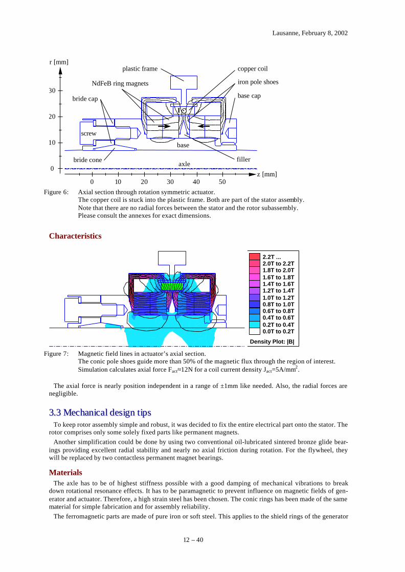
Characteristics
Density Plot: |B|
2.2T ...2.0T to 2.2T1.8T to 2.0T1.6T to 1.8T1.4T to 1.6T1.2T to 1.4T1.0T to 1.2T0.8T to 1.0T0.6T to 0.8T0.4T to 0.6T0.2T to 0.4T0.0T to 0.2T
Figure 7: Magnetic field lines in actuator’s axial section.The conic pole shoes guide more than 50% of the magnetic flux through the region of interest.Simulation calculates axial force Fact≈12N for a coil current density Jact=5A/mm2.
The axial force is nearly position independent in a range of ±1mm like needed. Also, the radial forces arenegligible.
33..33 MMeecchhaanniiccaall ddeessiiggnn tt iippssTo keep rotor assembly simple and robust, it was decided to fix the entire electrical part onto the stator. The
rotor comprises only some solely fixed parts like permanent magnets.Another simplification could be done by using two conventional oil-lubricated sintered bronze glide bear-
ings providing excellent radial stability and nearly no axial friction during rotation. For the flywheel, theywill be replaced by two contactless permanent magnet bearings.
MaterialsThe axle has to be of highest stiffness possible with a good damping of mechanical vibrations to break
down rotational resonance effects. It has to be paramagnetic to prevent influence on magnetic fields of gen-erator and actuator. Therefore, a high strain steel has been chosen. The conic rings has been made of the samematerial for simple fabrication and for assembly reliability.
The ferromagnetic parts are made of pure iron or soft steel. This applies to the shield rings of the generator

Lausanne, February 8, 2002
13 – 40
discs and to the pole caps of the actuator.All other parts were cut out of high strain aluminium blocs. The chosen aluminium alloy is easy to work
and offers an excellent mass/strain ratio [11]. The high strain is needed especially for the generator discs. At30krpm, due to their external diameter and the implanted magnets, the discs have to withstand maximal stressof about 100MPa in both radial and azimuthal direction [12].
Of course, industrial parts (screws) are just of standard materials (stainless steel...).
33..44 SSiiggnnaall pprroocceessssiinnggThe start point was the schema 1.
Actuator power supplyThe actuator coil dimensions have been given by the size of available permanent magnets. Limiting the
coils current density Jact<5A/mm2 [13], the current Iact was deduced.
Current: actactactact
actactact JdJ
NLT
I 2≈= [14]
The actuator current is designed to be a rather static DC current.
Voltage:( )
actact
actactactactactactact J
TDTLIRU 2
4
φρ
+≈=
If a simple diode is used instead of a full wave rectifier, the voltage loss across the diode is about 1V. To-gether with the loss in the generator coil, it leads to:
Total loss: actgenloss IRU += V1
The generator coils should work as differential pairs to supply themselves a linearly position dependentvoltage. But their resistive losses would double. For nominal actuator force at minimum speed and maximumexcursion of the rotor, they had to give at least a differential voltage of:
( ) ( )
( )
+++=
+++
++≈
+=∆
2222
2
2222
19.1mm8.41070mmV340V1
2224V1
actgengen
gengen
act
actactgengen
gengengengengen
act
actactactact
lossact
dd
TT
Jdd
WHTTLTDTL
UUU
φφµ
πφ
π
φρ
Used values:
m17A/mm5
mm104.2mm20mm3.0mm8.1mm1mm4
2 Ω==
======
µρact
gengengen
actactact
J
WLHTLD
Hgen and Wgen were set to the dimensions of the magnets used. Lgen was set to keep the coils in the intervalof variable magnetic flux as detailed in graph 2.
Furthermore, the voltage Ui is induced in the generator coils. At an excursion of 1mm, the flux densityvaries by ∆Bz≈45mT and, at minimum speed, the phase frequency is ω=10π·50Hz [15].
11 AlMgSiMn T6 has a density of 2.9g/cm3 and offers maximal resistance of at least 295MPa – the admissible steady stress
is about 150MPa.12 See “B.1 Centrifugal forces” for an example of calculation.13 Heating due to resistive loss limits the static current density to about 4A/mm2.14 Description of symbols in “A.1 Resistance and inductance of circular coil” and “A.2 Resistance and inductance of rec-
tangular coil”.15 The permanent magnets of the generator supply five full periods.

Lausanne, February 8, 2002
14 – 40
Induction:
2
2
2
2
2
20
2
Vm118
mm35.245Vm64.2
2
gen
gen
act
gen
gen
gengengen
actactz
gen
gengengengen
gengen
mgeni
d
T
d
d
T
WHL
JdB
d
WHTL
dt
dIL
dtd
NU
µ
µ
µω
≈
−=
+−∆≈
−Φ
=
Now, set Ui=∆U and solve for the undetermined variables while reducing the power loss Iact·Ui. Limit Tgento less than 7.5mm – say half the space between successive magnets.
The optimisation problem was solved on the computer. It showed that wire diameter has a minor influenceon the total power loss. For geometric reason, the condition Ui=∆U could not be fulfilled at minimum speedfor an excursion of 1mm. Why not increase the excursion? Well, stiffness does not change at all and, if ex-cursion exceeds about 1.5mm, Ui increases slower as a result of the magnetic flux density in the generator.
For this demonstrator, one single type of wire was used. So, dact=dgen=0.34mm and φact=φgen=0.30mm. Thevoltages reach ∆U=11.4V and Ui=7.7V for Tgen=7.5mm. This means that the nominal actuator force Fact=12Nis obtained only for rotor speed above 4´500rpm. Nevertheless, the system works as long as the axial stiffnessrests sufficiently high to beat the instability of the magnetic bearings. Otherwise, one could change to a non-linear feedback and use single coils instead of differential pairs.
Having several solutions in mind, an adjustable configuration was chosen. It seemed reasonable to use afour phase generator because it would suffice to provide a rectified low ripple voltage Uact. The actuatorpower is drawn from four coil pairs. Each pair can be reconnected for experimentation.
Note that stability benefits from a nearly constant Uact giving a constant actuator force. Note also that ifmore phases had been used, the generator coils would have been very close together – thus more difficult todesign and assemble. Not at least, the part of each generator coil to the total actuator power decreases withincreasing number of phases.
Modification of the regulatorAs drafted in schema 1, the regulator has to do a little more work than rectifying and buffering the power
arriving from the generator. The capability of withstanding steady forces is an obvious charge. Another is theneed for reasonable damping and high precision of the rotor position. Either one places shunt resistors paral-lel to the capacities, or one uses some active electronic parts.
Shunt resistors would introduce permanent power loss, so power MOSFETs has been preferred althoughtheir gates has to be driven by a DC voltage. Passive parts would need high sensor voltages together withprotecting Zener diodes to deduce the typical gate–source voltages from 4.5V at threshold to 20V at breakthrough. This would waste energy at higher rotation speed.
Finally, the use of a standard operation ampli-fier came in favour. Unfortunately, it demands aconstant supply voltage. On the other hand, it of-fers a far lower sensor threshold voltage forcomparison. So, it consumes less power to adaptthe sensor outputs to the amplifier inputs.
For the amplifier supply, a depletion modeMOSFET combined with a Zener diode gives afairly robust solution. The output voltage Usc
stays clamped to the sum of the Zener voltageand the gate–source threshold voltage. Advanta-geously, the Zener diode can be supplied by theoutput. Therefore, its current stays constant forany input voltage Uss.
LPleft
LSright
Lactuator
LPright
4x
l r
LSleft
Iact
Uact
LsupplyUss
Usc
Schema 2: Modified signal processing.

Lausanne, February 8, 2002
15 – 40
Regulator layoutFixing the concrete layout was not as easy as thought. The main problem was posed by the high dynamic
range of each voltage coming from a generator coil. In fact, system components supporting more than a tri-pling of input/output voltages are rare.
Voltage and current requirements:Operation amplifiers need a single supply from about 6V to 30V. If very low quiescent current is preferred,
most available amplifier support 6V to 15V.Power MOSFETs have typically a threshold voltage Uth from 2V to 6V. Maximum gate–source voltage UGS
is three to four times the threshold level but rarely above 20V. High maximum gate–drain voltage UGD anddrain–source voltage UDS is only available for Uth>4V.
As calculated above, the actuator power supply coils createpeak voltages of 7.7V at 3´000rpm, thus about 80V at 30krpm!Considering that a switched inductance induces voltage spikes,UDS>120V was preferred. In this range, available transistorssupporting drain currents ID>1A have Uth≈4.5V and UGS=20V[16]. Or, UGS imposes that the transistor sources are both con-nected to a floating mass of half the operation amplifier supplypotential. So, the drains are kept away from the more sensibleelectronic parts. They are separately connected by rectifier di-odes to the generator coils.
The operation amplifier output drives both gates. At highlevel, its output must be above Uth but below –Uth [17] at lowlevel. Therefore, an amplifier [18] having more than 12V outputdynamic was chosen. A 13V supply seemed reasonable, ena-bling a ±6.5V output range.
LPleft
LPright
4x
Lactuator
Iact
Ugs
½Usc
Schema 3: Switch configuration.
The amplifier supply coil has to give a peak voltage of about 15V at 3´000rpm. After passing through arectification diode, buffering and reduction by a voltage regulator, it will just rest the constant 13V supplyvoltage. It follows the same game as above: 15V at 3´000rpm ⇒ 150V at 30krpm. With a depletion modepMOSFET and a 12V Zener diode, it was possible to supply the amplifier by drawing <50µA ⇒ 7.5mWpeak consumption!
Finally, the sensor coils were chosen. The higher their peak voltage,the higher the voltage difference would be for a given excursion of therotor position. But the higher the voltage, the higher the consumptionand the more difficult the link from coil output to amplifier input. Agood compromise was found with a peak voltage from 4V at 3´000rpmto 40V at 30krpm. A resistance in series with a high pass filter limits thevoltage range at 3.5V to 9V. After rectification and low pass filtering,each sensor output links to an amplifier input.
Note that extraneous sensor coils were required due to the differentvoltage requirements of the actuator and the amplifier.
UsensorLS HP
LP
Schema 4: Sensor adaptation.
Regulator requirements:Not knowing the exact behaviour of the system, it seemed reasonable to preview a variety of possible con-
figurations for the amplifier inputs/output. The idea was to have a circuit allowing a quick modification of theregulator behaviour. The layout allows to reconfigure the amplifier as a proportional (P), differential (D) orcombined (PD or even PD2) regulator.
33..55 EElleeccttrriiccaall ddeessiiggnn tt iippssAs a basic rule, keep circuit simple and put close together what is linked. The use of a mass plane can re-
duce electromagnetic noise too. Separate low and high voltage subcircuits and, only if necessary, link themby a single potential.
16 Refer to the datasheets “IRF9640 HEXFET® Power MOSFET” and “IRF620 HEXFET® Power MOSFET”.17 In reference to the source potential = floating mass potential. See “D. Circuit of signal processing unit”.18 Consult the datasheet “LMC6042 CMOS Dual Micropower Operational Amplifier”.

Lausanne, February 8, 2002
16 – 40
For convenience, use two operation amplifiers in series. The first calculates the difference of its input volt-ages and adjusts them to an arbitrary ground level. The second implements the PID regulator by comparingthe output of the first amplifier to the chosen ground level. In general, ground level should be about half thesupply voltage to work at best amplification and CMRR of the amplifiers.
Take care about voltage spikes appearing on a switched inductance. For example, use a double Zener diodeas protection against disastrous spikes. Finally, do not forget to eliminate current loops where possible.

Lausanne, February 8, 2002
17 – 40
44.. RReeaalliissaattiioonn
44..11 PPrroobblleemmss dduurriinngg ccoonnssttrruuccttiioonn
Mechanics [19]
The design asked for 10mm long glide bearings. Because of the very restraint quantity – two in this case –the trader did not order specially this length and furnished glide bearings 13mm long instead. Advanta-geously, the axle support was made moveable and able to handle bearing lengths up to 15mm.
The axle endings were at tolerance but not at the demanded surface quality. They needed manual polishingand decanting to prevent any damage of the bearings. In fact, if the axle does not fit into the bearings withoutnotable resistance, it is a good idea to inspect their contact surfaces.
The coaxial alignment of the bearings was a critical point. Because of mismatched axle supports, the axleblocked whenever inserted into both bearings. To not rework the supports and the base plate, some thin metalpieces/papers were put under the axle supports – just for adjustment.
Finally, almost all dedicated parts were made of an aluminium alloy which made it simple to match thepermanent magnets into their openings. The openings were fitted quite fast to exactly the needed dimensions.
Electronics [20]
The circuit did not pose problem at assembly time. But as formerly previewed, the regulator was somewhatdifficult to adjust [21]. As predicted in “ 2.2 System stability”, the rotor oscillated nervously around the centreposition if a simple proportional regulation was used. Its oscillation frequency was about 2Hz to 10Hz de-pending upon the connections of the generator coils.
Quickly, a proportional/differential (PD) regulator showed useful. It was able to damp the oscillation fairlywell without introduce a significant regulation error.
Several coil connections were experimented. Finally, all non-proportional solutions had to be given up inlack of a reasonable regulation. These configurations created up to ten times higher actuator forces than theretained solution, but the oscillation could not be suppressed. A more powerful regulator would allow to
a) profit from the repulsive force in the generator if only one half the coils power the actuator at the sametime
b) connect the generator coils in parallel, thus multiplying the actuator current [22].
MiscellaneousThe used triphase asynchronous motor did not reach 30krpm. Although it spun up to 10krpm in reasonable
time, its acceleration decreased for higher speeds. The effect was well notable and limited the rotor speed toabout 12´500rpm. It is thought that its iron lamellas for the rotor and stator were too thick and therefore re-jected the magnetic flux at higher frequency. In fact, the effect was always noted in common with the appear-ance of an axial force rejecting the rotor out of the stator cage, whereas it was pulled into before.
44..22 CChhoosseenn rreegguullaattoorr bbeehhaavviioouurrAs a result of experimentation, these passive electronic parts were assigned to the following values [20]:
C3 = 1.5µF R2 = 4.7kΩ R3 = 0 (wire) R6 = 220Ω R7 = 100kΩ
The other parts with unspecified values were not used. This concerns C4, R4, R5 and R8.
This regulator configuration sets the static regulator gain Kp= –R7/R2 to 21. The gain starts increasing at afrequency fz≈1/2πC3(R4+R6)=22Hz and stops at fp≈1/2πC3R6=480Hz at Kp´ =Kp(R2+R6)/R6=475. It came outthat the regulator mainly eliminates the integration effect introduced by the sensor input stages to keep con-stant the mean voltages for any rotation speed. They have a cut off frequency at 63Hz for a better comparebut destabilise the system meanwhile.
19 A description on how to build the demonstrator is given in “C. Assemblage”.20 Consult “D. Circuit of signal processing unit” for more information.21 It’s a good idea to use sockets for the parts configuring the regulator behaviour.22 This solution corresponds to a non-linear ‘staircase’ regulation (quick advance, waiting, fast withdraw).

Lausanne, February 8, 2002
18 – 40
55.. VVeerriiffiiccaattiioonnThe generator was configured for the attractive mode offering more coil interconnection possibilities. The
stiffness at centred position will not significantly increase for repulsive mode because, at the closer vicinity ofthe permanent magnets [23], the axial magnetic flux derives as well for both configurations.
First, some electrical characteristics were verified [24]. The data was taken with inactive motor to prevent get-ting noisy values. In fact, the PWM motor driver introduces heavy spiking – a good reason to take a slower op-eration amplifier for the signal processing unit.
Second, mechanical characteristics have been determined – as are maximal drawback force and stiffness whileregulating the axial position of the rotor. The axial force was given mainly by the actuator, while the generatorand the motor created lower forces by side effects. The system characteristics were determined by measuring theactuator current for a given rotor excursion. The axial force was then calculated from the actuator’s force–currentratio [25], neglecting the contribution of the generator.
-3.0
-2.0
-1.0
0.0
1.0
2.0
3.0
2.2 2.4 2.6 2.8 3.0 3.2 3.4 3.6 3.8z [mm]
Fact [N]3740rpm6520rpm8810rpm
Graph 4: Axial restoring forces and stiffness.Note that the z axis has an arbitrary reference. Concentrate on the stiffness k corresponding to theslope |dFact/dz|.
The graph shows the influence of the diodes used to rectify the actuator current. Its trace is a smaller slopearound the zero crossing of the actuator force Fact at lower rotation speeds. The maximal measure error for theaxis position is estimated to ±0.06mm, for the rotation speed to ±1% and for the force Fact to ±0.2N.
Assuming a constant slope, the stiffness was determined to:a) 2.5kN/m±0.3kN/m @ 3´740rpm±40rpmb) 8.1kN/m±0.9kN/m @ 6´520rpm±65rpmc) 9.7kN/m±0.9kN/m @ 8´810rpm±90rpm
This can be resumed by a constant 20%rpm1N/m1
±⋅==rotor
actdz
dFK
ω.
23 Remember that the generator coils were put exactly in this region.24 See “E.1 Generator” for detailed characteristics.25 Refer to “E.2 Actuator” for measurements.

Lausanne, February 8, 2002
19 – 40
66.. CCoonncclluussiioonnThe demonstrator was realised and tested.
The chosen design allows various experiments. Quick changes in generator configuration and regulator be-haviour are particularly simple – just reconnect some generator coils or replace some passive electronic parts ofthe regulator.
The system proved its function. The axial restoring force was measured at several rotor positions and speeds.So, the stiffness was evaluated to be 1N/m·rpm±20% giving about 2kN/m at minimal respectively 25kN/m atmaximal rotation speed. This is many times better than for an unregulated passive magnetic bearing but stillsmall compared to the demanded stiffnesses from 100kN/m to 10MN/m.
The currently used regulator was not able to suppress the self-resonance whenever a non-linear feedback wastested. Thus, by means of a more powerful regulator, it should be feasible to benefit from the full generatorpower increasing the axial stiffness above 100kN/m for any rotation speed.