Embed Size (px)
Citation preview
Development of an In Vitro Outer Annulus Fibrosus-
Cartilage Endplate Model and its Response to Dynamic
Mechanical Loading
by
Jasmine E. Chong
A thesis submitted in conformity with the requirements
for the degree of Masters of Applied Science
Institute of Biomaterials and Biomedical Engineering
University of Toronto
© Copyright by Jasmine E. Chong 2019
ii
Development of an In Vitro Outer Annulus Fibrosus-Cartilage Endplate Model
and its Response to Dynamic Mechanical Loading
A thesis submitted in conformity with the requirements for the degree of
Masters of Applied Science
Institute of Biomaterials and Biomedical Engineering
University of Toronto
© Copyright by Jasmine E. Chong 2019
ABSTRACT
Tissue-engineering research to date has neglected to address the annulus fibrosus (AF)-
cartilage endplate (CEP) interface of the intervertebral disc. It was hypothesized that in vitro-
formed outer AF and cartilage tissues will integrate in co-culture to form an interface
containing ECM that resembles the native interface, and that can be mechanically and
compositionally enhanced through dynamic loading. 2-week old in vitro OAF tissues
integrated with 3-day old in vitro cartilage by 1 week of co-culture, and resembled the
distributions of collagen type I, collagen type II, and aggrecan seen in the native interface.
The apparent tensile strength of the in vitro interface increased between 2 and 4 weeks of co-
culture. Dynamic mechanical loading did not enhance the mechanical strength, appearance,
or composition of the interfacial matrix. This study demonstrated the ability to engineer a
biological AF-CEP interface model, and will assist in defining how future tissue-engineered
disc replacements should be developed.

iii
ACKNOWLEDGEMENTS
I would like to thank my supervisors Dr. Rita Kandel and Dr. Paul Santerre for their guidance
and encouragement over the course of my degree. I would also like to thank my committee
members Dr. Craig Simmons and Dr. Marc Grynpas for their input and assistance during the
completion of my project.
It has been a pleasure to work with all members of the Kandel Lab, who have not only provided
me with assistance when in need, but have given me countless memories I will always look back
on with a great big laugh. A special thanks goes to Jian Wang at the Faculty of Dentistry. Never
before have I been so pleasantly surprised when we serendipitously discovered our mutual
obsession with street photography, which never failed to keep the conversation interesting and
enlightening during those long and would-be tedious mechanical testing sessions.
Thanks to my parents, who have constantly supported me in more ways than one: To my mother
for always keeping me very well fed, and to my father whom I could always count on to be my
own personal machine shop technician or to let me borrow tools, electrical tape, and random
pieces of plexiglass during my own personal desperate times of lab-related MacGyver-ing. I
hope that whatever I achieve in the future pays off for you both.
iv
TABLE OF CONTENTS
Abstract ........................................................................................................................................... ii
Acknowledgements ........................................................................................................................ iii
Table of Contents ........................................................................................................................... iv
List of Tables ............................................................................................................................... viii
List of Figures ................................................................................................................................ ix
List of Supplementary Figures ........................................................................................................ x
List of Appendices ......................................................................................................................... xi
List of Abbreviations .................................................................................................................... xii
CHAPTER 1: Introduction ............................................................................................................. 1
1.1 Introduction ........................................................................................................................... 1
1.2 Hypothesis ............................................................................................................................. 5
1.3 Objectives .............................................................................................................................. 5
CHAPTER 2: Literature Review .................................................................................................... 7
2.1 Intervertebral Disc ................................................................................................................. 7
2.1.1 Embryonic Development of the Intervertebral Disc .................................................... 10
2.1.1.1 Extracellular Matrix Components of the Developing Intervertebral Disc ............. 14
2.1.2 Nucleus Pulposus.......................................................................................................... 15
2.1.3 Annulus Fibrosus .......................................................................................................... 17
2.1.4 Cartilage Endplate ........................................................................................................ 18
v
2.2 The Annulus Fibrosus-Cartilage Endplate Interface ........................................................... 19
2.3 Degenerative Disc Disease .................................................................................................. 23
2.3.1 Current Treatment Strategies for Degenerative Disc Disease ...................................... 26
2.3.1.1 Injectable Biomolecules ......................................................................................... 27
2.3.1.2 Cell-Based Therapies ............................................................................................. 28
2.4 Intervertebral Disc Tissue-Engineering .............................................................................. 32
2.4.1 AF Tissue Engineering ................................................................................................. 33
2.4.2 Electrospun Aligned Nanofibrous Polymer Scaffold for Multilamellar Tissue-
Engineered AF ....................................................................................................................... 37
2.4.3 Tissue-Engineered IVD-CEP Integration ..................................................................... 40
2.5 The Role of Mechanical Stimulation on Extracellular Matrix Composition ...................... 42
CHAPTER 3: Development of an In Vitro Outer Annulus Fibrosus-Cartilage Endplate Model
and its Response to Dynamic Mechanical Loading ...................................................................... 53
3.1 Introduction ......................................................................................................................... 53
3.2 Methods ............................................................................................................................... 56
3.2.1 Isolation of OAF cells .................................................................................................. 56
3.2.2 Generation of aligned nanofibrous PU-ADO scaffold constructs ................................ 57
3.2.3 Formation of hyaline cartilage tissue in 3D culture ..................................................... 58
3.2.4 Fluorescent labelling of primary chondrocytes ............................................................ 59
3.2.5 Co-culture of in vitro-formed OAF and cartilage tissues ............................................. 60
vi
3.2.6 Determination of mechanical loading magnitude ......................................................... 62
3.2.7 Dynamic mechanical loading of OAF-CEP constructs ................................................ 65
3.2.8 Pull-apart testing of OAF-CEP constructs ................................................................... 66
3.2.9 Histological characterization of native and in vitro OAF-CEP interface ..................... 69
3.2.10 Immunohistochemical characterization of the OAF-CEP interface model ................ 69
3.2.11 Quantification of DNA, collagen, and proteoglycan contents ................................... 70
3.2.12 Statistical analysis ...................................................................................................... 72
3.3 Results ................................................................................................................................. 73
3.3.1 Co-culture of in vitro OAF on cartilage tissue generated an integrated tissue
interface ................................................................................................................................. 73
3.3.2 Chondrocytes remained localized to the cartilage layer beneath the interface ............ 78
3.3.3 Immunohistochemical characterization of the bioengineered OAF-CEP
interface ................................................................................................................................. 79
3.3.4 Apparent mechanical strength of the in vitro OAF-CEP interface increased
over time ................................................................................................................................ 82
3.3.5 No significant difference in OH-Pro or GAG content between 2 and 4 weeks of
co-culture ............................................................................................................................... 84
3.3.6 A compressive force of 0.4 N resulted <10% radial strain in OAF tissues .................. 86
3.3.7 Dynamic mechanical stimulation did not significantly increase the apparent
tensile strength, collagen content, or proteoglycan content in OAF-CEP interface
constructs ............................................................................................................................... 88
vii
CHAPTER 4: Discussion .............................................................................................................. 92
4.1 Summary ............................................................................................................................. 92
4.2 Discussion and Study Limitations ....................................................................................... 93
4.2.1 Use of in vitro-formed OAF tissue on aligned angle-ply PU-ADO nanofibrous
scaffolds and hyaline-like cartilage are suitable to generate an OAF-CEP model................ 93
4.2.2 Requirements for successful co-culture of in vitro OAF and cartilage tissues ............ 95
4.2.3 Characterization of the OAF-CEP interface ................................................................. 98
4.2.4 Failure testing and apparent mechanical strength of the OAF-CEP interface ............ 102
4.2.5 Dynamic mechanical loading of the in vitro OAF-CEP interface .............................. 108
4.3 Recommendations for Future Work .................................................................................. 113
4.4 Conclusions ....................................................................................................................... 116
CHAPTER 5: References ........................................................................................................... 118

viii
LIST OF TABLES
Table 1: Literature review summary of mechanical loading effects on IVD and
cartilage cells and tissue……………………………………………………………43-48
ix
LIST OF FIGURES
Figure 2.1: Schematic diagrams of the native IVD……………………………………………... ..9
Figure 2.2 Schematic diagrams of IVD development ……………………………………….13-14
Figure 2.3 DIC image of AF fibre bundle insertion into the native CEP……………………….. 19
Figure 2.4 DIC image of AF fibres pulling out VB osteons during tensile testing……………...22
Figure 3.1: Schematics showing cell isolation and tissue culture methods…………………..61-62
Figure 3.2: Determination of compressive load parameters for OAF + agarose plug………..64-65
Figure 3.3: Loading of OAF-CEP constructs in a Mach-1™ mechanical tester………………... 66
Figure 3.4: Pull-apart failure testing and OAF surface area measurement.………………….68-69
Figure 3.5: Schematic diagram of OAF-CEP interface preparation for biochemical analysis…..72
Figure 3.6: Histological appearance of in vitro and native OAF-CEP interface …………….75-76
Figure 3.7: Histological appearance 3-day old, 5-day old, and 7-day old cartilage tissues
interfaced with OAF or cultured alone……………………………………………77-78
Figure 3.8: CFDA-labelled chondrocytes in OAF-CEP constructs……………………………..79
Figure 3.9: Immunostaining of in vitro and native OAF-CEP interface for collagen type I,
collagen type II, and aggrecan…………………………………………………….81-82
Figure 3.10: OAF-CEP apparent stress and histological appearance at failure ……………..83-84
Figure 3.11: Biochemical analysis of DNA, GAG, and OH-Pro contents between 2 and
4-week old interface constructs………………………………………………………85
Figure 3.12: Determination of loading parameters by mechanical testing of OAF
and agarose plug constructs…………………………………………………….....87-88
Figure 3.13: Effect of dynamic loading on mechanical strength, histological
appearance, and ECM composition at the OAF-CEP interface……………………90-91
x
LIST OF SUPPLEMENTARY FIGURES
Figure S1: Appearance of cultured OAF-CEP constructs with and
without physical tubing………………………………………………………..150-151
Figure S2: Method of scaffold strip cutting……………………………………………………152
Figure S3: Fluorescent CFDA labelling of chondrocytes…………………………………….. 153
Figure S4: Set-up diagrams for dynamic loading…………………………………………154-155
Figure S5: Method of cryotape sectioning………………………………………………...156-157
Figure S6: Nanofiber alignment confirmation by SEM………………………………………. 157
Figure S7: Resemblance between in vitro and native OAF by immunostaining……………....158
Figure S8: Histological appearance of variations in construct integration…………….............159
Figure S9: In vitro cartilage grown alone in AF-optimized media versus control
Ham’s F12 conditions……………...……………...………………………………160-161
Figure S10: Appearance of paucicellular cartilage layer by immunostaining…………………161
xi
LIST OF APPENDICES
APPENDIX A: Method Development for In Vitro OAF-CEP Construct Assembly ................. 149
APPENDIX B: Supplementary Figures ...................................................................................... 150
xii
LIST OF ABBREVIATIONS
ADO Anionic dihydroxyl oligomer
AF Annulus Fibrosus
CEP Cartilage endplate
CFDA 5,6-carboxyfluorescein diacetate
CPP Calcium Polyphosphate
DAPI 4’6-diamidino-2-phenylindole
DAPS Disc-like angle ply structure
DDD Degenerative disc disease
DIC Differential interference contrast
DMEM Dulbecco's modification Eagle's medium
DMSO Dimethyl sulfoxide
DNA Deoxyribonucleic acid
DTT Dithiothreitol
ECM Extracellular matrix
EDTA Ethylenediaminetetraacetic acid
FBS Fetal bovine serum
GAG Glycosaminoglycan
GDF-5 Growth differentiation factor-5
H&E Hematoxylin & eosin
HA Hyaluronic acid
HSC Hematopoietic stem cell
hMSC Human mesenchymal stem cell
xiii
IAF Inner annulus fibrosus
IgG Immunoglobulin G
iPSC Induced pluripotent stem cell
ITS Insulin-transferrin-selenium
IVD Intervertebral disc
MMP Matrix metalloproteinase
MRI Magnetic resonance imaging
MSC Mesenchymal stem cell
NP Nucleus pulposus
OAF Outer annulus fibrosus
OH-Pro Hydroxyproline
PBS Phosphate buffered saline
PCL Polycaprolactone
PLA Polylactic acid
PLGA Poly(lactic-co-glycolic acid)
PRP Platelet-rich-plasma
PU Polycarbonate urethane
PU-ADO Polycarbonate urethane-anionic dihydroxyl oligomer
SEM Scanning electron microscopy
SLRP Small leucine-rich proteoglycan
TBS Tris buffered saline
TE Tissue-engineered
VB Vertebral body
1
CHAPTER 1: INTRODUCTION
1.1 Introduction
The intervertebral disc (IVD) is a fibrocartilaginous tissue that permits flexibility and load
transmission between adjacent vertebral bodies in the spine. It consists of a central gel-like
nucleus pulposus (NP) and a surrounding annulus fibrosus (AF). Relative to the rest of the disc,
the NP contains the highest content of collagen type II and aggrecan, a proteoglycan that
provides the tissue with compressive-resistant properties. The content of both of these
extracellular matrix (ECM) macromolecules progressively decreases, while collagen type I
increases, towards the outermost part of the AF. The AF is a complex concentric, multi-
lamellated, angle-ply fibrous structure; collagen fibres of successive lamellae are oriented at
opposing ~30° angles to each other. It is further subdivided into inner (IAF) and outer (OAF)
regions. The IAF contains collagen type I, collagen type II, and rounded cells. The OAF is more
organized than the IAF and consists mostly of highly aligned collagen type I fibres and elongated
fibroblastic cells. Cartilage endplates (CEP) composed of hyaline cartilage are located cranially
and caudally to each disc and provide anchorage of the soft IVD into the hard vertebral bone
(VB). Within the CEP, a layer of calcified cartilage lies immediately adjacent to the VB which
acts to further strengthen the disc-cartilage-bone anchorage system1. The CEP and the periphery
of the OAF contain small blood vessels, which likely provide routes of nutrient transport to the
IVD via diffusion2-4. Despite peripheral contacts with these small capillaries, overall the IVD is
an avascular tissue that is housed in a low-oxygen environment. At approximately 6000
cells/mm3, the human IVD has an even lower cell density than articular cartilage, which is in
itself known to be a tissue of low cellularity2. Poor vascularity in conjunction with low cellularity
2
severely limits the IVD’s capacity for self-repair, and degenerative processes once initiated are
irreversible.
Degenerative disc disease (DDD) is associated with lower back pain5,6, and at advanced stages
can lead to decreased disc height, AF tearing, and disc herniation7. Conservative treatment of
back pain symptoms with physical therapy, analgesics or muscle relaxants does not target the
underlying tissue pathology of DDD. Surgical approaches for treatment of advanced DDD
include discectomy, spinal fusion, and prosthetic disc replacement, however these do not
guarantee long-term pain relief. These procedures have been reported to have low overall success
rates and may lead to complications such as adjacent disc degeneration8,9.
Cell-based strategies for DDD that have been implemented at the clinical level include
intradiscal placement of autologous bone marrow-derived mesenchymal stem cells (MSCs)10,11,
allogeneic bone marrow-derived MSCs12, passaged allogeneic juvenile chondrocytes (NuQu®,
ISTO Technologies Inc.)13, and autologous cultured disc cells (chondrotransplant® DISC,
co.don)14. Although the results from these studies suggested that such cell-based treatments were
able to reduce pain and disability scores over time, the long-term outcomes of these studies past
2 years, including adverse effects, are unknown. It is unclear whether the injected/implanted cells
exerted their effects by targeting underlying degenerative processes. It is also not known whether
the implanted cells acquired and/or sustained a disc cell-like phenotype, nor whether they
promoted the appropriate regional ECM production; these limitations are especially true for the
intradiscal implantation of marrow-derived MSCs and passaged juvenile chondrocytes. Although
in vitro studies have induced MSCs to differentiate towards AF and NP cell-like phenotypes15-17,
3
acquisition and maintenance of the correct phenotypes are difficult to achieve. Hyaline cartilage-
producing chondrocytes are phenotypically distinct from IVD cells18,19, and intradiscal
implantation of these cells might have unknown long-term adverse effects. While autologous
disc cells might seem like a solution to circumvent the phenotypic challenges presented by MSCs
and chondrocytes, intradiscal placement of these cells by injection is not expected to restore the
exact structural organization of the native disc. Therefore, a bioengineered implant solution
composed of IVD cells seeded within a biomimetic IVD scaffold structure might be able to
replicate the form and function of the native IVD in such a way that prosthetic replacements or
intradiscal cellular injections cannot achieve.
A major challenge of IVD tissue engineering is accurate reproduction of the complex AF
structure and organization. Furthermore, studies to date that have generated whole TE-IVD
implant models have simplified AF construction by overlooking the distinct inner and outer
regions. AF cell-seeded collagen hydrogels have been used for AF generation, but they have not
shown the ability to mimic every individual structural feature of the AF within a single IVD
construct. Photochemical cross-linking of successive collagen layers around an NP-like hydrogel
core was achieved in order to mimic the multi-lamellar feature of the AF, but was unable to
generate aligned or angle-ply features20. Collagen gels were also contracted around an NP-like
hydrogel core to produce circumferential alignment of collagen fibres, however an angle-ply
structure was not achievable by this method21. Other IVD models have made use of AF cell-
seeded porous lamellar silk22 and micropatterned bacterial cellulose scaffolds23 in IVD implant
construction, which were able to address the circumferential, multilamellar, and aligned angle-
ply structural components. However, production of biological materials such as collagen, silk, or
4
bacterial cellulose may not be as efficient or fine-tunable as the production of a synthetic
polymer, which may be considered to be a better alternative for reproducible large-scale AF
scaffold generation. Current TE whole IVD implant models have utilized electrospun
nanofibrous aligned polymer scaffolds to mimic all the structural components of the AF24-28.
Strips of aligned nanofibrous scaffold can be fashioned into concentric multilamellar angle-ply
constructs. In comparison to scaffolds containing randomly oriented nanofibers, directional
alignment of nanofibrous polymer scaffolds promotes alignment and morphological elongation
of seeded AF cells, which subsequently enhances the production of AF-specific ECM
components29. Aligned nanofibrous scaffolds made from electrospun polycarbonate urethane
with added anionic dihydroxyl-oligomer (PU-ADO) have been shown to support the
maintenance of separately cultured IAF and OAF cell phenotypes, as well as the distinct region-
specific ECM accumulation of each respective AF region30,31.
Tissue engineering research has made much progress in the generation of a structurally accurate
TE IVD, however ensuring appropriate and stable integration of TE implants with surrounding
tissue in vivo remains difficult. In vitro culture of bovine AF cell-seeded nanofibrous angle-ply
structures showed accumulation of collagen and GAG-containing ECM, however upon
implantation into rats these constructs extruded from the disc space28. Although an acellular
porous polymer that was subsequently incorporated into the model acted as a bony endplate and
improved integration upon implantation of the whole TE IVD28, inclusion of a CEP layer to more
accurately model the anchorage that normally occurs between the native IVD and VB was
neglected. Achieving integration of engineered IVD and cartilage tissues prior to implantation is
a necessary next step towards the development of a more complete disc replacement model.
5
Determination of applicable treatments to enhance the integration process in vitro is also of
interest in order to maximize the potential for implant success. Dynamic mechanical loading is
one such treatment that has been shown to have anabolic effects on ECM by stimulating
macromolecule gene and protein expression, and potentially by reducing ECM degradation32-53.
While the anabolic effects of dynamic compressive and tensile loading have been shown in
cartilage and IVD tissues and cells, the effect on the IVD-CEP interface is unknown. The current
thesis investigates the development of a bioengineered nanofibrous scaffold-based AF-CEP
interface model, and the potential for dynamic mechanical stimulation to enhance interfacial
tissue formation and strength. OAF cells will be used in the generation of this model as a primary
step towards producing an AF-CEP model that has differentiated inner and outer regions.
1.2 Hypothesis
In vitro OAF tissue grown on aligned nanofibrous multi-lamellated PU-ADO scaffolds will
integrate in co-culture with in vitro cartilage tissue grown on a porous Teflon membrane, to 1)
form an interface containing ECM that resembles the native OAF-CEP junction in its cellular
composition and immunolocalization of collagen type I, collagen type II and aggrecan, and 2)
that can be mechanically and compositionally enhanced through dynamic loading.
1.3 Objectives
1) Generate an in vitro OAF-CEP interface model using primary bovine OAF cells, primary
bovine articular chondrocytes, and an electrospun nanofibrous PU-ADO scaffold

6
2) Characterize the OAF-CEP interface tissues in vitro and determine the effect of culture
time on their development and integration through histological examination and
mechanical axial tensile testing
3) Determine the effect of dynamic compressive loading on in vitro OAF-CEP interface
ECM accumulation and mechanical strength
7
CHAPTER 2: LITERATURE REVIEW
2.1 Intervertebral Disc
The IVD is located between adjacent vertebral bodies and functions to permit flexibility and load
transmission within the spine. It is composed of a central collagen type II and proteoglycan-rich
nucleus pulposus (NP) that is contained by a surrounding annulus fibrosus (AF). Hyaline
cartilage endplates (CEP) located superiorly and inferiorly attach each disc to adjacent vertebral
bodies (Figure 2.1). The IVD is an avascular tissue located in a low oxygen environment,
however it obtains its nutrients via diffusion from small blood vessels that can be found around
the outermost periphery of the AF2. Blood vessels also extend from the subchondral bone,
through the bony vertebral endplates and into the CEP, however there is not clear evidence that
the latter extend from the CEP into the disc4,54. Human cranial vertebral endplates were recently
found to contain a significantly higher number of marrow openings in comparison to caudal
endplates, suggesting that the IVD relies more heavily on blood supply originating from the
adjacent cranial vertebra versus the caudal vertebra55. The average water content in the human
disc is approximately 75%, with ~10% higher content in the NP when compared to the AF56,57.
Relative to the NP, the AF has approximately double the collagen as determined by
hydroxyproline content per dry weight, and half the proteoglycan content as estimated by
spectrophotometric assay via dimethylmethylene reactivity57. The ratio of proteoglycan to
collagen in the NP is far greater when compared to the AF and CEP, which were found to be
27:1, 1.6:1, and 2:1 respectively in healthy human adult tissues by glycosaminoglycan (GAG) to
hydroxyproline dry weight18.
8
The main collagens that comprise the IVD are the fibrillar collagen types I and II, which are
characteristic structural proteins of tensile-resistant fibrous tissues and compressive-resistant
cartilage tissues, respectively58. Collagen type I fibrils pack parallel to each other in an aligned
fashion giving these fibres tensile strength, whereas collagen type II fibrils are less organized and
interact with ECM proteoglycans to resist compressive loads59,60. Collagen type I is highly
abundant in the OAF and decreases centrally as the NP is approached, while collagen type II is
most highly abundant centrally in the NP and decreases laterally towards the OAF58. Collagen
type III has been found to be mainly pericellular within the disc, although its role is unclear61.
Collagen type VI is found in the translamellar bridges of the AF and may have a role in collagen
bundle lubrication62. Collagen type X, which is a marker of hypertrophic chondrocytes involved
in mineralization, can be found in the native disc-vertebra interface63.
Proteoglycan content of the IVD is highest within the nucleus pulposus and lowest in the OAF,
with percent water content generally following the same trend56. The main proteoglycan found in
the IVD and CEP is aggrecan, which is similar to collagen type II in its regional distribution and
in its role to provide compressive resistance64. It exists within the extracellular matrix (ECM) in
the form of aggregates, whereby large numbers of aggrecan molecules are bound to hyaluronic
acid. Its osmotic properties allow it to swell and resist compression when hydrated. Lubricin, a
lubricating proteoglycan that is known to be produced by superficial zone articular
chondrocytes65, has also been identified in human IVD. While lubricin staining was found to be
distributed diffusely throughout the human disc, the NP and IAF stained more intensely
compared to the OAF66. In contrast, lubricin in mature goat IVD was not found in the NP nor the
IAF but was rather localized to the OAF lamellae and interlamellar junctions, and to the
9
intracellular regions of AF and NP cells in primary monolayer culture67. The contrasting results
between the two studies may be attributed in part to species differences and/or effects of
degeneration in the cadaveric adult human specimens. Despite these differences, both studies
highlighted that the presence of lubricin might have a functional role in IVD biomechanics.
Lubricin is known to reduce friction at the articulating surfaces of synovial joints68. IVDs from
lubricin knockout mice were found to have greater rotational stiffness when compared to wild
type controls, indicating that lubricin might have a similar role in the IVD to facilitate proper
mechanical function69.
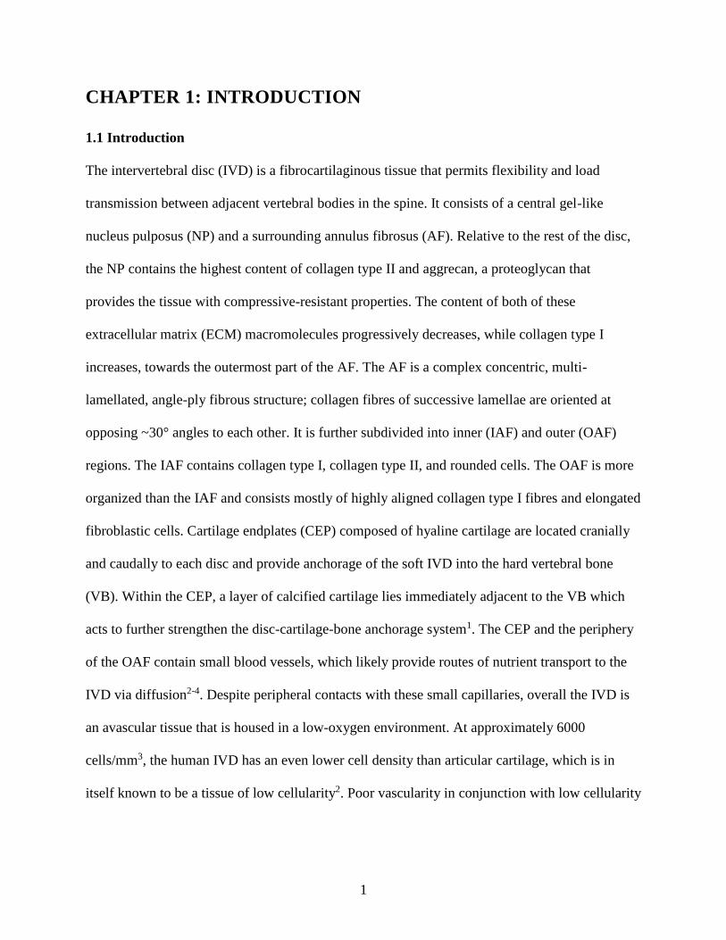
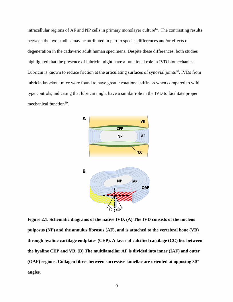
Figure 2.1. Schematic diagrams of the native IVD. (A) The IVD consists of the nucleus
pulposus (NP) and the annulus fibrosus (AF), and is attached to the vertebral bone (VB)
through hyaline cartilage endplates (CEP). A layer of calcified cartilage (CC) lies between
the hyaline CEP and VB. (B) The multilamellar AF is divided into inner (IAF) and outer
(OAF) regions. Collagen fibres between successive lamellae are oriented at opposing 30°
angles.
10
2.1.1 Embryonic Development of the Intervertebral Disc
In embryonic development of the vertebral column, the NP originates from the rod-like
notochord and its surrounding notochordal sheath, while the AF, CEP, and vertebral bodies arise
from sclerotomal cell condensations of the mesoderm7. Prior to the formation of cell
condensations, sclerotome cells are round in shape70. By approximately day 30 of human
embryogenesis, sclerotome cells have aggregated around the notochord to form a metameric
pattern of loose and dense condensations that will later give rise to the vertebral bodies and the
AF, respectively (Figures 2.2A-D)7,70. The densely packed sclerotome cells elongate to adopt a
fibroblastic morphology and align into sheets of oppositely angled cells (Figure 2.2E)70,71.
Concentric alignment of these cells precedes the deposition of ECM and gives rise to the
lamellar structure seen in the fully developed AF71. This highly organized structural architecture
is established before the vertebral column experiences any external mechanical stress caused by
movement70. The notochord regresses and eventually disappears at the level of the developing
vertebral bodies, while it bulges within the intervertebral tissue (E16 in the rat)70,71. It has been
suggested that mechanical force from the developing vertebral bodies puts pressure on the
intervertebral notochord and causes it to bulge70. This notochordal bulging might promote the
differentiation of the fibrocartilaginous AF tissue into its inner and outer regions, as these two
developmental events coincide with each other71. At E15 in the rat there is very little ECM, the
notochord is a continuous rod-like structure, and differences in morphology between IAF and
OAF are discernable72. After E16, AF differentiation is marked by the orientation of fibroblastic
AF cells into angle-ply lamellae and the appearance of collagen types I and II in the OAF and
IAF respectively, which appear as histologically distinct tissues58,73. Hayes and colleagues
11
showed the presence of cell-cell contacts by electron microscopy and positive immunostaining
for the adherens junction components cadherins and vinculin, in cells of the developing rat OAF
at E1572. Positive immunostaining for integrin α1 and β1 subunits as well as vinculin indicated
that cell-ECM contacts were also present in the form of focal adhesions in the developing OAF
at this stage. Actin was diffuse throughout at E15, however by the time of notochordal bulging at
E16, actin stress fibres were prominent and longitudinally oriented within the aligned fibroblastic
cells of the developing OAF. Pericellular fibronectin was diffuse throughout the disc until E16,
at which point it organized longitudinally around OAF cells and appeared to mirror the
intracellular organization of actin stress fibres. The authors suggested from the collective
evidence that cell-cell and cell-ECM contacts are required to establish aligned AF cell
orientation and actin stress fibres, which in turn mediate the longitudinal organization of
pericellular fibronectin that ultimately guides the assembly of aligned collagen deposition72.
SEM images from a later study showed that the orientation of extracellular collagen fibrils
between AF cells did indeed follow the path of longitudinal intracellular stress fibres73.
Cadherins in the developing OAF was no longer detectable by E17 and stress fibres were absent
by birth, suggesting that the mediators of cell-cell interactions and cellular orientation were no
longer required by the time of ECM deposition. Vinculin and integrin subunit expression
persisted throughout development, suggesting that cell-matrix interactions were necessary for the
continued organized deposition of ECM after the establishment of cellular orientation72.
The vertebrae and CEP embryonic cartilage anlagen develop from the loose sclerotomal cell
condensations. At the region of the developing CEP, cells are aligned horizontally, parallel to
adjacent vertebral bodies70. In humans, AF collagen fibres form interconnections with the CEP
12
by the seventh embryonic month, and CEP collagen fibres are oriented parallel to adjacent
vertebral bodies74. The fibrils of the OAF are joined with the uncalcified region of the peripheral
CEP cartilage that will later ossify to become the vertebral rim74. CEP thickness is greatest in the
immature spine and decreases with age as the outermost region becomes calcified75.
13
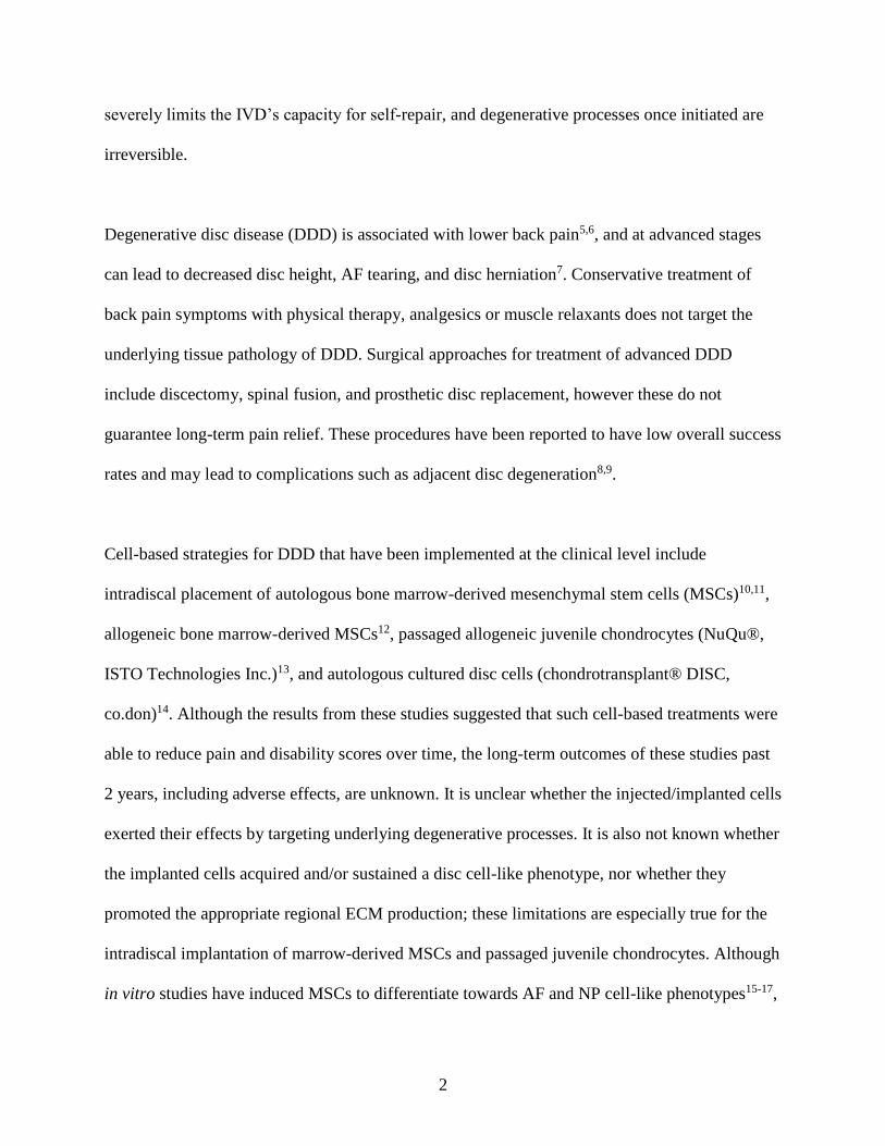
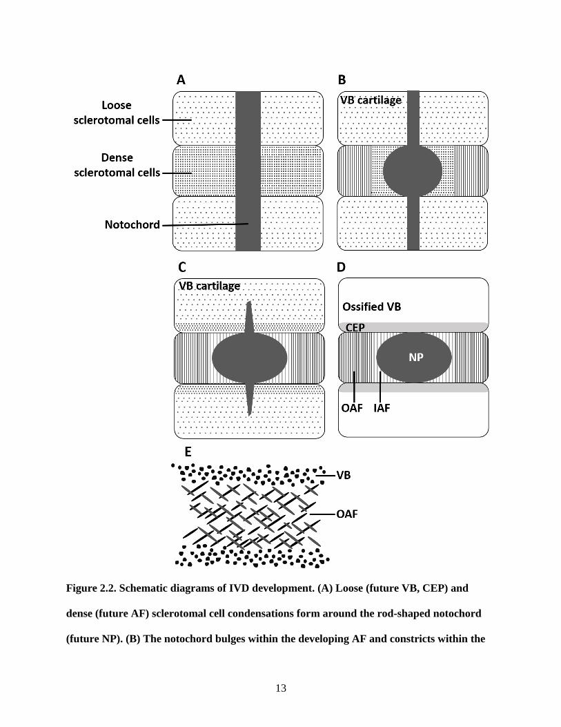
Figure 2.2. Schematic diagrams of IVD development. (A) Loose (future VB, CEP) and
dense (future AF) sclerotomal cell condensations form around the rod-shaped notochord
(future NP). (B) The notochord bulges within the developing AF and constricts within the
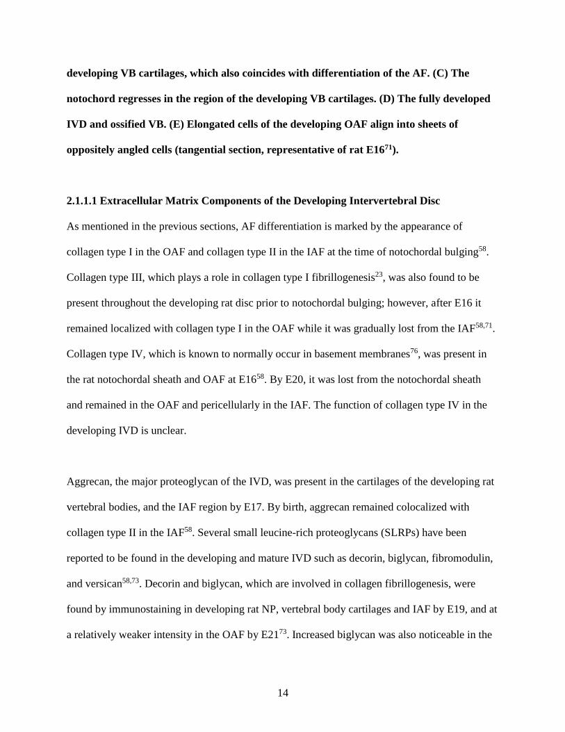
14
developing VB cartilages, which also coincides with differentiation of the AF. (C) The
notochord regresses in the region of the developing VB cartilages. (D) The fully developed
IVD and ossified VB. (E) Elongated cells of the developing OAF align into sheets of
oppositely angled cells (tangential section, representative of rat E1671).
2.1.1.1 Extracellular Matrix Components of the Developing Intervertebral Disc
As mentioned in the previous sections, AF differentiation is marked by the appearance of
collagen type I in the OAF and collagen type II in the IAF at the time of notochordal bulging58.
Collagen type III, which plays a role in collagen type I fibrillogenesis23, was also found to be
present throughout the developing rat disc prior to notochordal bulging; however, after E16 it
remained localized with collagen type I in the OAF while it was gradually lost from the IAF58,71.
Collagen type IV, which is known to normally occur in basement membranes76, was present in
the rat notochordal sheath and OAF at E1658. By E20, it was lost from the notochordal sheath
and remained in the OAF and pericellularly in the IAF. The function of collagen type IV in the
developing IVD is unclear.
Aggrecan, the major proteoglycan of the IVD, was present in the cartilages of the developing rat
vertebral bodies, and the IAF region by E17. By birth, aggrecan remained colocalized with
collagen type II in the IAF58. Several small leucine-rich proteoglycans (SLRPs) have been
reported to be found in the developing and mature IVD such as decorin, biglycan, fibromodulin,
and versican58,73. Decorin and biglycan, which are involved in collagen fibrillogenesis, were
found by immunostaining in developing rat NP, vertebral body cartilages and IAF by E19, and at
a relatively weaker intensity in the OAF by E2173. Increased biglycan was also noticeable in the
15
IAF and at the AF-vertebra interface by E21. Both decorin and biglycan were associated with
CEP cells at 4 months after birth73. Immunoblotting showed an increased presence of decorin in
the AF of 2 and 10-year old sheep compared to undetectable amounts in fetal samples77,
suggesting that its content further increases with maturity. Fibromodulin is the most predominant
SLRP found in the developing AF and likely has roles in fibrillogenesis and lamellar
organization73. Fibromodulin was localized to the rat IAF and AF-vertebra interface at E17. Its
distribution extended into the vertebral body cartilages by E19 and to the OAF by E21, and
persisted throughout the AF after birth73. Versican was reported to be present in ovine AF
interlamellar junctions and translamellar bridges, and might have a possible role in collagen
bundle lubrication62,77. Immunostaining showed that native young bovine IAF contained more
versican than OAF, which was reflected by the finding that primary cultured bovine IAF cells
accumulated more versican over time compared to OAF cells30. However, Hayes et al. described
the distribution of versican in the developing rat IVD which was at first predominant in the IAF
and posterior OAF at E17, but absent from the IAF by birth58. As such, it was reported here that
versican colocalized with collagen type I and was only present in the OAF. The inconsistent
findings regarding versican localization in inner versus outer AF may be in part due to
differences between species.
2.1.2 Nucleus Pulposus
The NP is the central region of the IVD and is mainly subjected to compressive loading. It is a
hydrated gel-like tissue that is mainly composed of collagen type II and aggrecan30,78. The
collagen fibril network organization in the NP is irregular79. Tensile failure testing suggested that
the collagen fibres of the NP are longer and more highly convoluted in the central region
16
compared to the peripheral region80. Elastin in the NP forms an organized network of fibres that
run both radially towards the AF and vertically to anchor into the CEP81. At the interface
between the NP and CEP, elastic fibres in the NP are parallel to each other and run vertically
towards the endplates81.
The cell population in the NP is mixed, consisting of small chondrocyte-like NP cells and
clusters of large notochordal cells that have vacuoles and dense cytoplasmic actin82,83.
Differential gene expression has been shown between these two cell populations84. Although NP
cells are often considered to be “chondrocyte-like”, it has been suggested that these cells are
differentiated notochordal cells and therefore do not originate from the same mesenchymal
lineage as chondrocytes. Porcine NP notochordal cells subjected to hydrostatic pressure
transitioned into small NP cells, and time-lapse imaging of rabbit NP notochordal cells also
showed differentiation into smaller chondrocyte-like cells85,86. Aging may be involved in the
progressive loss of notochordal cells in certain species, including humans. Loss of notochordal
cells with age has been shown in some species such as mongrel dogs and sheep, while they
persist with maturity in other species such as rat and rabbit82. Older, more degenerated NP
tissues from non-chondrodystrophoid dogs were shown to have a loss of vacuole-containing,
actin-rich notochordal cells compared to NP from younger, healthier discs83. Human notochordal
cells were found to be present in clusters in early fetal development (embryonic week 8),
however were undetectable in adult human specimens87. Degenerative processes are also likely
to be involved in notochordal cell loss. An in vivo mouse model of degeneration by needle
puncture showed a decrease of NP notochordal cells and an increase of NP chondrocyte-like
cells within 2 weeks of injury compared to unpunctured controls88.
17
2.1.3 Annulus Fibrosus
The AF experiences axial compression; longitudinal, radial, and circumferential tension; shear
stress between adjacent lamellae and at the interfacing CEP; and torsion. It is a heterogeneous,
multi-lamellar structure comprised of aligned collagen fibres that are alternately angled at
approximately 30° with respect to the vertical axis89. It is further distinctly subdivided into the
outer (OAF) and inner (IAF) regions. The OAF is composed of aligned, highly organized type I
collagen fibre bundles and elongated fibroblast-like cells, whereas the IAF is less organized and
contains proteoglycans, type I and type II collagen, and rounded cells7,90. OAF cells have a
polarized, spindle-shaped morphology and express cell polarity proteins Par3, claudin-1, and
claudin-11 to a higher degree as compared to IAF or NP cells91. Directed ECM secretion by
polarized OAF cells may in part be responsible for the organized aligned structure of OAF
lamellae91.
The spaces between adjacent lamellae, or interlamellar junctions, are proteoglycan-rich and
contain organized networks of elastic fibres as shown by both orcein staining and elastin
immunostaining62,92. The interlamellar elastic fibre network is loose compared to the densely
packed collagen fibres of the lamellae; tension and shear testing demonstrated that failure
occurred at the interlamellar matrix and not within the lamellae93. The interlamellar junctions
form continuous connections with proteoglycan-rich translamellar cross-bridges, which are
predominantly found in the mid-AF and appear as transverse discontinuities within the
lamellae62. These interconnecting cross-bridges become more numerous with increasing age,
may function to prevent delamination, and have been suggested to be the remnants of regressed
18
blood vessels62,94,95. In addition to containing collagen type I and elastin, the interlamellar
junctions and translamellar cross-bridges contain localized collagen type VI, aggrecan, and
versican62. While the function of collagen type VI in these regions is unknown, it has been
suggested that it is a marker of fibrocartilage differentiation96. Aggrecan and collagen VI have
also been found between collagen fibre bundles in the fibrocartilaginous region of the bovine
deep digital flexor tendon which experiences both tension and compression during locomotion,
suggesting that these molecules might have potential roles in resisting both compressive and
tensile forces within the IVD96,97. It has also been suggested that aggrecan and versican within
the interlamellar matrix may serve to lubricate collagen fibre bundles and prevent damage to
them during loading62.
2.1.4 Cartilage Endplate
A hyaline cartilage endplate (CEP) lies on either side of the IVD (cranially and caudally),
adjacent to the vertebral bone. Collagen fibres are aligned horizontally with respect to the
adjacent disc and vertebral body79. This layer, which serves as the interface between the disc and
the bone, is reported to have a thickness of approximately 0.6-0.8 mm in adult humans and
resembles articular cartilage in that it contains chondrocytes within an ECM rich in collagen type
II and proteoglycans57,98. An uncalcified cartilaginous region is adjacent to the disc, and a
mineralized region is adjacent to the vertebral bone63. The transition from uncalcified to calcified
cartilage within the CEP occurs sharply in a step-wise fashion rather than in a progressive
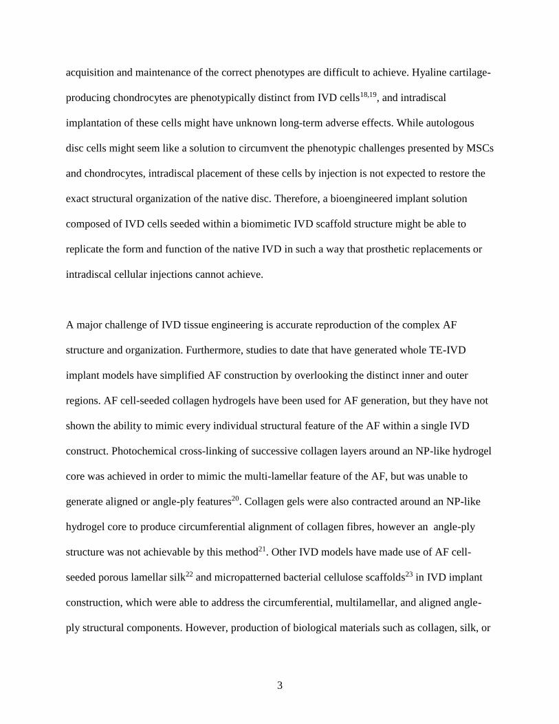
gradient99. Collagen fibres within the CEP are oriented horizontally57. Collagen fibres of the AF
insert vertically through the CEP (Figure 2.3), into the calcified region and into the vertebral
bone, forming the AF-CEP interface that is crucial for the distribution of mechanical
19
load63,100,101. Vertical insertion of AF fibres through the CEP confers tensile-to-shear stress
transfer, whereby the direct application of tensile stress (from spinal extension/flexion/lateral
bending) is transferred into shear stress along the length of the AF fibre which is embedded
within the cartilaginous matrix100,102. It has also been proposed that splitting of AF fibre bundles
into sub-bundles within the CEP matrix further enhances anchorage and resistance to tensile
stress by increasing the AF fibre-CEP matrix contact area100,101.
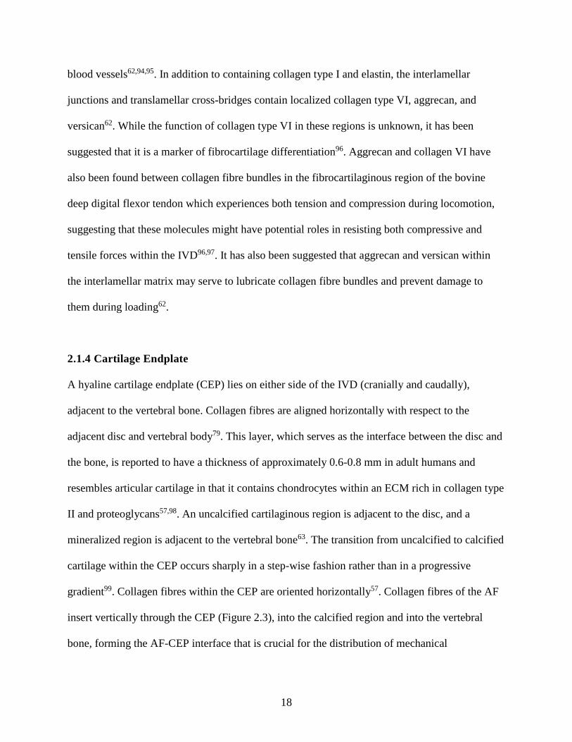
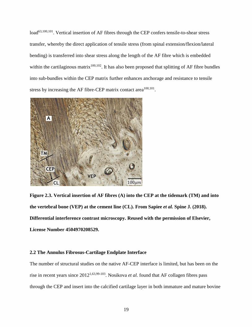
Figure 2.3. Vertical insertion of AF fibres (A) into the CEP at the tidemark (TM) and into
the vertebral bone (VEP) at the cement line (CL). From Sapiee et al. Spine J. (2018).
Differential interference contrast microscopy. Reused with the permission of Elsevier,
License Number 4504970208529.
2.2 The Annulus Fibrosus-Cartilage Endplate Interface
The number of structural studies on the native AF-CEP interface is limited, but has been on the
rise in recent years since 20121,63,99-103. Nosikova et al. found that AF collagen fibres pass
through the CEP and insert into the calcified cartilage layer in both immature and mature bovine
20
discs. While fibres from both the IAF and OAF insert through the hyaline CEP and into the layer
of calcified cartilage, the outermost OAF fibres also curve laterally towards the outer aspect of
the vertebral bone to merge with the cartilage63. The AF-CEP interface contains AF cells that are
aligned with the inserting collagen fibres, as well as chondrocytes that are clustered within a
proteoglycan-rich ECM63. AF collagen fibre bundles embedded within the CEP exhibit a wave-
like crimped morphology, a feature which allows for flexibility in the AF when it undergoes
tension (i.e. affords higher mechanical compliance, as crimps will uncoil under tension to
accommodate deformations)100,101. Upon insertion into the CEP, this characteristic crimp is
absent. A structural study by Paietta et al. of human disc-vertebra samples aged 56 days to 84
years found that while the hyaline CEP is present throughout maturity in the IAF region, the
adult OAF region only contains calcified cartilage and subchondral bone, indicating that the
hyaline CEP is remodeled and mineralized with age. The layer of calcified cartilage was uniform
in the infant and thicker in the OAF and vertebral rim regions with increasing maturity99. Elastic
fibres have also been reported to anchor the AF into the CEP104.
There is conflicting evidence in the literature regarding the degree of AF fibre insertion past the
CEP, however recent studies appear to confirm that insertion indeed extends to the vertebral
bone1,100-103. Rodrigues et al. stated in 2012 that fibre bundles from the mid-AF region in ovine
discs branched into sub-bundles and inserted into the CEP, with no further insertion into the
vertebral endplate100. Berg-Johansen et al. concluded from tensile testing, histology, and
scanning electron microscopy (SEM) imaging of adult human cadaveric thoracic spine
specimens, that AF fibres did not insert into the subchondral bone, that the CEP-vertebral bone
interface lacked structural interconnectivity and that it was therefore weakly integrated103.
21
Despite these findings, compelling evidence argues against a lack of integration at the interface.
After initially reporting that AF fibres insert through the CEP only, Rodrigues et al. found in
2015 that mature ovine AF sub-bundles did indeed insert through the CEP, into the calcified
cartilage and, to a limited extent into the vertebral endplate bone1. Sapiee et al. recently proposed
the presence of robust anchorage of AF fibres through the CEP and into the vertebral bone in
ovine lumbar specimens, and furthermore that this anchorage is independent of CEP
mineralization102. In this latter study, tensile testing and SEM imaging were performed to show
that AF and CEP fibrils interconnected with the vertebral endplate, where they inserted between
osteons and amongst the bony fibrils. After selective demineralization of endplate regions,
tensile testing of vertebral segments showed that some osteons of the vertebral endplate
remained attached to the pulled-out AF sub-bundles. The results indicated that AF fibres were
structurally integrated with the vertebral bone independent of the CEP mineralized layer. The
authors suggested that four modes of AF fibril insertion are generally present in their integration
with the bony endplate: Perpendicular insertion between bony fibrils; oblique insertion between
bony fibrils; abrupt ending at the bony layer without insertion; and intermingling with bony
fibrils in an irregular fibrillar network102. Adding to the evidence for structural integration shown
in sheep, a human study by Junhui et al. similarly found that AF fibre sub-bundles extended
through the CEP and into the vertebral endplate101. The conflicting findings between the two
human studies may be attributed to the use of older cadaveric human specimens (49-65 years) by
Berg-Johansen et al. as compared to the younger specimens (22-57 years) studied by Junhui et
al. All human specimens examined by Berg-Johansen et al. and were in fact graded above 1, at a
range between 2-4 (average 2.6) according to the Thompson Grade scale of 1 (“healthy”) to 5
(“severely degenerated”)103. In addition, Junhui et al. produced numerous high magnification
22
histological images compared to the limited low-magnification images provided by Berg-
Johansen et al. As such, the evidence supporting structural integration at the human AF-CEP-
bone interfaces was arguably superior and more thorough than the evidence for a lack of
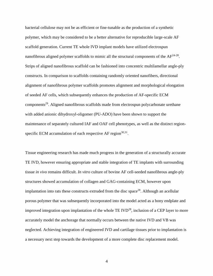
integration. High magnification SEM images in the ovine study by Sapiee et al. also provided
compelling proof to support not only that the AF integrates with the CEP, but that its insertion
and interconnectivity with the vertebral bone play important roles in the anchorage system
(Figure 2.4).
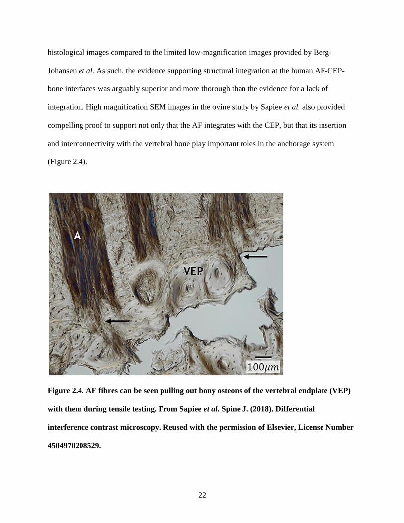
Figure 2.4. AF fibres can be seen pulling out bony osteons of the vertebral endplate (VEP)
with them during tensile testing. From Sapiee et al. Spine J. (2018). Differential
interference contrast microscopy. Reused with the permission of Elsevier, License Number
4504970208529.
23
In addition to being the site where attachment and mechanical load transfer occur between the
disc and vertebral bone100,101, the CEP may also directly modulate IVD maintenance through the
inhibition of matrix-degrading enzymes and inflammatory cytokines by secreting modulatory
molecules105,106. Compared to in vitro-formed NP tissue grown alone, NP tissue grown in the
presence of native CEP or in vitro-formed cartilage showed increased proteoglycan content and
decreased protein expression of the matrix metalloproteinase MMP-13, likely due to decreased
gene and protein expression of the proinflammatory cytokine tumor necrosis factor-α105. Trauma
to the CEP may also promote IVD degeneration by inducing both necrotic and apoptotic IVD
cell death, and by increasing collagenase gene expression106. Although the mechanisms of any
direct signalling effects between the CEP and IVD are unknown, it is critical to consider their
integration in order to move towards developing a more complete IVD implant model given the
structural, mechanical, and biological relationships that are known to exist between them.
2.3 Degenerative Disc Disease
Degenerative disc disease (DDD) is associated with lower back pain5,6 and can be attributed to a
combination of different factors such as genetic predisposition, mechanical overloading,
immobilization, and aging107-109. It has been suggested that males are more susceptible to IVD
degeneration earlier and to a higher degree compared to females108. The average cell density of
the human IVD has been reported to be approximately 6000 cells/mm3, approximately 2.5 times
lower than that of articular cartilage which in itself is known to be a tissue of relatively low
cellularity2. Decreased cellularity was found in the AF and NP of old-aged (≥80 years) compared
to middle-aged (35-50 years) human discs55, adding support to the idea that decreases in cell
number with age further reduces the disc’s ability to maintain synthetic function, thus leading to
24
degradative changes in the matrix. In addition, the tissue is poorly vascularized and the dense
matrix likely provides a barrier to cell entry and migration. The capacity for IVD self-repair is
therefore low and the process of degeneration once initiated is irreversible. Normal matrix
remodelling, whereby homeostatic matrix macromolecule degradation and synthesis during
growth and development occur, is impaired in DDD. An increase in denatured collagen type II
and a decrease in procollagen type II was found in Thompson grade 4 degenerated human discs
when compared to grade 1-3 discs, indicating that more advanced degeneration is in part due to
an imbalance in matrix turnover that favours collagen type II degradation over synthesis110. In
addition, increased fibrotic matrix synthesis was evidenced by the finding that procollagen type I
levels, indicative of collagen type I synthesis, were significantly higher in grade 4 discs
compared to grade 2 or 3 discs110. Higher degenerative grade was also associated with decreased
GAG content and a correlated decrease in water content when compared to lower degenerative
grades110. Thinning of collagen fibrils in human AF and NP has been associated with increasing
age and may also be a result of degenerative processes in the IVD55.
Decreased protein content and a loss of uniform distribution of aggrecan, the major proteoglycan
of the IVD, is seen in the AF of degenerated IVDs111. This is mirrored by a decrease in aggrecan
gene expression, as well as downregulation of aggrecanase genes that may be important in the
regulation of normal aggrecan turnover111. Interestingly, human IVD aggrecan extracts inhibited
human neuroblastoma cell line neurite growth and repelled chick dorsal root ganglia explant
growth in a concentration-dependent manner, implying that degenerative aggrecan loss may
partially contribute to increased innervation of the disc resulting in pain112. Decreased aggrecan
content also prevents the tissue from maintaining hydration and may contribute to enhanced AF
25
tearing that is seen with degeneration111. AF tearing may initiate and/or accelerate further
degeneration113. Using magnetic resonance imaging (MRI) and the Pfirrmann MRI grading scale
for disc degeneration114, it was shown in human patients that the presence of annular tears was
associated with higher disc degeneration grades and significantly increased disc degeneration
grades at a 2-year follow-up compared to discs without annular tears113. Advanced degeneration
is marked by an overall reduction in structural IVD integrity in the form of reduced disc height,
annular tears, bulging, and herniation7. Other degenerative changes to the disc and its
environment include SLRP fragmentation, increased apoptotic cell death, increased matrix
degrading enzymes, and an increase in inflammatory cytokines115-118.
Mechanical overloading has been implicated in the progression of DDD. Mechanical overloading
of goat IVDs by axial compression led to increased collagen disorganization and a reduced
proteoglycan to collagen ratio when compared to unloaded control IVDs119. Increasing time and
magnitude of static compressive loading has also been linked to apoptotic cell death120,121. While
unloaded control and sham IVDs showed minimal apoptotic cell death, the relatively lowest
mechanical stress levels induced cell death in the IAF, and the relatively higher stress levels and
longer durations led to more extensive cell death in the CEP and NP121. The number of apoptotic
CEP chondrocytes in organ cultured mouse IVDs increased as the degree of static compressive
loading increased from 0 to 1.0 MPa120.
Pathologic changes of the CEP in relation to aging and disc degeneration include reduced
thickness, point defects, and reduced permeability leading to decreased nutrient transport122-124.
Reduced disc nutrition and subsequent degeneration may also result from the obstruction of
26
vascular channels that pass from the vertebral bone marrow to the CEP. Decreased marrow
contact channel number and size in vertebral endplates was linked to increased Thompson
degenerative grade125. Endplates having fewer channel openings per unit surface area also had
decreased proteoglycan content in the NP region when compared to endplates having more
openings. Likely due to calcification, the loss of channel openings presumably leads to decreased
capillary blood supply to the endplates and consequently decreased disc nutrition and waste
removal by diffusion, which may then promote degenerative changes to the disc125. Ariga et al.
found structural degeneration and an increase in apoptotic cells in the CEP of naturally aging and
surgically-induced spondylotic rats, and suggested that pathologic changes in the CEP precede
degenerative changes in the disc126.
2.3.1 Current Treatment Strategies for Degenerative Disc Disease
Conservative treatments such as analgesics, muscle relaxants, and physical therapy are used to
treat the symptoms of back pain but not the underlying tissue pathology127,128. Current surgical
treatments for degenerated and herniated discs include discectomy, spinal fusion, and prosthetic
disc replacement. Removal of herniated disc tissue by discectomy reduces disc height and does
not guarantee long-term pain relief, as up to 25% of patients may experience recurrent back pain
and disability 2 years postoperatively14,129. Prosthetic disc replacement is a newer procedure that
maintains the motion segment and is theoretically meant to overcome some of the limitations of
spinal fusion9. However, complications arising from prosthetic disc replacement include adjacent
segment degeneration, prosthesis migration, and wear of the implant material130. One meta-
analysis reported total disc replacement as having a higher success rate, superior clinical
outcomes, and a lower incidence of adjacent segment degeneration when compared to
27
discectomy and fusion131. Other reports have shown contradictory findings and suggested that
both procedures have low overall success rates, no significant clinical outcome differences, and
similar levels of adjacent disc degeneration8,9,132.
2.3.1.1 Injectable Biomolecules
Clinical trials have investigated the efficacy of injectable biomolecules for DDD therapy such as
growth differentiation factor-5 (GDF-5) and platelet-rich-plasma (PRP). In vivo animal studies in
rabbits133 and mice134 have shown that a single intradiscal injection of GDF-5 was associated
with increased disc height and improve degeneration grade compared to untreated discs. A Phase
II clinical trial has been conducted to assess the safety and tolerability of recombinant human
GDF-5 intradiscal injection, the results of which have not yet been published135. While GDF-5 is
now being investigated clinically as a potential biological treatment for DDD, it should be noted
that multiple intradiscal injections of GDF-5 in mice did not have an effect on disc height and in
fact elicited an inflammatory response134. Further work is required to assess its clinical efficacy
and safety. PRP is an autologous source of cytokines, growth and differentiation factors, and
adhesion molecules that are known to be involved in tissue healing136. A bovine study
investigating the effects of PRP administration on AF cells in vitro and whole discs ex vivo found
increased GAG production when compared to untreated cells and discs137. PRP-treated AF cells
also showed increased DNA content over time when compared to untreated cells, implying a
PRP-induced increase in cell proliferation137. However, results from intradiscal PRP injection in
rabbits indicated that PRP did not increase IVD cell proliferation but rather decreased
apoptosis138. Preliminary clinical trials evaluating the efficacy of intradiscal PRP injection have
found improved patient-reported outcomes of back pain and function over follow-up periods of
28
6-12 months139,140. One double-blind, randomized control study reported significant
improvements in self-reported pain, physical function, and satisfaction in patients who received a
single intradiscal PRP injection compared to control patients who received an injection of
contrast agent141. Any biological effects of PRP on patient disc tissue are unknown as they were
not evaluated in these studies. Although radiographic evidence reported by Akeda et al. showed
that PRP-treated discs did not show further ossification or height reduction over time, there were
no differences between treated (L4/L5 level) and untreated (L3/L4 level) discs of the same
patients139. Conclusions about the clinical efficacy of PRP in the intervention of disc
degeneration therefore cannot be drawn. It is still unknown whether PRP specifically targets the
underlying pathologies of DDD, alters pain, or even whether it is an appropriate treatment for
advanced stages of degeneration.
2.3.1.2 Cell-Based Therapies
Cell-based therapies aim to replace cells, restore normal disc biology, and are perhaps of
potential interest for more advances stage of DDD. Clinical intradiscal implantation of
autologous and allogeneic stem cells, allogenic chondrocytes, and autologous disc cells have
been investigated.
Autologous mesenchymal stem cells (MSCs), which can be isolated from autologous bone
marrow or adipose tissue, are of great interest due to their multilineage differentiation potential
and have been shown to be safe and feasible for the treatment of DDD142. Autologous
hematopoietic stem cell (HSC) delivery by direct intradiscal injection of bone marrow aspirate
was not found to be an effective clinical intervention as none of the patients reported reductions
29
in discogenic pain in the year following treatment143. Patients further underwent spinal fusion or
disc replacement surgery after study completion. Although the authors of this study claimed to
have injected HSCs, the marrow aspirate was not processed to isolate specific cell fractions, nor
was the cell population characterized. A more thorough clinical study utilized an isolation and
centrifugation processing system to obtain an autologous bone marrow aspirate progenitor cell
concentrate, which was then injected intradiscally144. The cell preparation was also characterized.
The cell preparation contained progenitor cells characteristic of MSCs as determined by in vitro
assay of fibroblast colony-forming units, and was positive for MSC markers CD90, CD105, and
CD34. Results suggested that bone marrow aspirate containing higher MSC concentrations
compared to those containing lower MSC concentrations led to greater decreases in patient-
reported pain and disability, and to improvements in disc hydration in some patients as
determined by MRI. Despite encouraging results, treatment efficacy appeared to depend on the
patient-specific MSC numbers in each autologous preparation, suggesting that this treatment
might not be a universally appropriate for all patients. Two human trials of intradiscal autologous
mesenchymal stem cell implantation have been published10,11. Yoshikawa et al. presented case
studies of 2 women who received intradiscal graft implants consisting of collagen sponges
seeded with autologous bone marrow-derived MSCs that had been precultured (2-week culture in
one case; 4-week culture in other case) and confirmed for cell proliferation. 2 years following
surgery, patients in both cases reported improved pain and disability scores and showed evidence
of improved disc hydration as determined by T2-weighted MRI signal intensity10. In a pilot
clinical investigation by Orozco et al., ten patients diagnosed with chronic back pain and lumbar
DDD received intradiscal injection of autologous bone marrow-derived MSCs that had been
precultured for 7-10 days11. Patient-reported pain and disability scores improved significantly 3
30
months following the procedure, with further improvements at 6 and 12 months. MRI revealed
that although disc height was not significantly different after each follow-up period, treated discs
showed increased hydration after 12 months. A more recent clinical study was reported to be the
first to see a significant association between MRI metrics and improvements in pain scores after
intradiscal injection of culture-expanded bone marrow-derived autologous MSCs145. 85% of the
treated patients showed decreased disc bulging by MRI imaging, which was related to decreased
pain scores relative to baseline reports. Allogeneic MSCs, which was reported to be more
convenient than autologous MSCs with respect to immediate availability for use in the clinic,
were investigated in a randomized clinical trial12. MSCs were derived from the bone marrow of
healthy donors that were not immune-matched to recipients, expanded for 27 days, and injected
intradiscally. Treated patients reported improvements in pain and disability scores as compared
to the sham-treated control patients at a 12-month follow up, and no significant immune
responses were found12,146. Although MRI imaging showed an improvement in degenerative
grade for MSC-treated compared to control patients, disc height and water content were not
shown to be significantly improved12. It is not shown from these clinical studies whether the
intradiscally transplanted MSCs resolved the underlying degenerative processes. Evidence from
a large-animal (porcine) study suggested that intradiscal delivery of MSCs slows down, rather
than resolves, degeneration147. It is also not known whether the implanted/injected cells acquired
and sustained a disc cell-like phenotype. MSCs have been induced in vitro to differentiate
towards both AF and NP cell-like phenotypes, supporting the idea of pre-culturing MSCs
towards a disc cell-like phenotype prior to implantation15-17. However, acquisition of the correct
phenotype, long-term phenotype maintenance, and the determination of optimal differentiation
conditions remain challenging.
31
Induced pluripotent stem cells (iPSCs) are also of interest as a possible cell source for DDD
treatment. Human somatic cells can be reprogrammed into iPSCs, which then have the capacity
for directed pluripotent differentiation148. Recent in vitro work has demonstrated the ability to
reprogram human NP cells isolated from DDD patients into iPSCs, and subsequent induction of
these iPSCs back into NP-like cells149. Despite this potential, there are currently no published
clinical studies that investigate the efficacy of iPSCs in humans150. Clinical use of both MSCs
and iPSCs poses further safety concerns such as potential for tumour and osteophyte
formation150,151.
Alternatively, a primary disc cell source is perhaps more attractive due to the difficulty of
inducing MSCs to express the correct phenotype. Results from a preliminary clinical study
suggested that intradiscal injection of passaged allogeneic juvenile chondrocytes (NuQu®, ISTO
Technologies Inc.) led to improved disc contour, improved disc height, and diminished annular
tears at 6-month follow-up13. Scores of patient-reported pain and disability significantly
decreased up to 12 months after treatment. However, clinical use of this allogeneic cell treatment
may be limited by the availability of cadaveric juvenile donors, and by costly cell expansion and
cryobanking procedures152. Additionally, chondrocytes produce hyaline cartilage and are
phenotypically distinct from NP cells and certainly from fibrocartilage-producing AF cells18,19. It
is unknown whether intradiscal implantation of these cells will have long-term adverse effects.
Autologous cultured disc cell transplantation (chondrotransplant® DISC by German company
co.don) was investigated in a clinical trial by the name of EuroDisc14. The chondrotransplant®
32
DISC procedure involved removal of herniated disc tissue during regular discectomy, disc cell
isolation and expansion in culture, and intradiscal injection of expanded cells back into the
patient 3 months after the initial discectomy153. Treated patients received discectomy and
subsequent cell transplantation while control patients received discectomy alone. Pain and
disability scores were lower in patients who received the treatment compared to control patients
at a 2-year follow up. Treated discs also showed a higher percentage of normal fluid content
when compared to control discs at 2-year follow up14. However, statistical significance was not
reported for either outcome, and follow-up was not extended past 2 years. While the results of
this study provide some evidence to support the use of autologous disc cells as a treatment, cell
administration by injection is not expected to restore structural organization of the normal disc.
A tissue-engineered therapy that combines autologous cells and a structural template might
therefore be a solution to replicate both form and function of the normal native disc.
2.4 Intervertebral Disc Tissue-Engineering
Research focused on tissue-engineered IVD implant models is currently in the pre-clinical
stages. IVD tissue engineering research has focused on disc models that include only AF and
nucleus pulposus components20,154-157, or the CEP alone158. Many bioengineered IVD models do
not distinguish OAF from IAF and utilize cells from the AF as a whole, thereby failing to
address the fact that the AF is a heterogenous tissue. Engineered IVD constructs have been
generated using collagen hydrogels20,154,159,160 as well as three-dimensional porous scaffolds
made from silk22,156,161, synthetic polymers162, and synthetic polymer/Bioglass composites163.
Regenerative strategies under investigation for NP tissue engineering are hydrogel or scaffold-
based164-166. Given that the gel-like NP lacks the structural complexity of the AF and is relatively
33
homogeneous in comparison, the greatest challenge in disc tissue-engineering research arguably
remains in accurately modeling the circumferential, aligned angle-ply, multi-lamellar structure of
the AF.
2.4.1 AF Tissue Engineering
Various approaches have been undertaken in an attempt to reproduce the specific structural
complexities of the AF. A biphasic IVD model by Choy and Chan mimicked the lamellar AF
structure by repeated photochemical cross-linking of up to 10 layers of collagen gels around a
collagen-GAG co-precipitate NP-like core20. Compared to the engineered constructs with fewer
collagen layers (1-4 layers), those with the highest number at 10 layers showed mechanical
properties similar to native disc. Moriguchi et al. constructed and assessed in vivo implantation
of a tissue-engineered (TE) canine IVD implant model made from a NP cell-seeded alginate gel
core surrounded by two layers of AF cell-seeded collagen gels, which contracted around the NP
core over a 2-week in vitro culture period160. Implanted TE IVDs stained positively for
proteoglycan and collagen by 4 weeks. At 16 weeks post-implantation, AF cells had a distinctly
elongated morphology compared to the rounded NP cells and appeared to align with the
concentric lamellae160. It is unknown from this study alone whether the aligned and elongated
phenotype expressed by AF cells in TE IVDs in vivo was a result of being seeded in a lamellar
structure, or if it was due to the innate behaviour of these cells regardless of scaffold structure.
Evidence that lamellar collagen fibre alignment promotes AF cell alignment was demonstrated
by Bowles et al. in a circumferential construct21. Collagen gels were contracted around a mandrel
to induce circumferential alignment of collagen fibrils. Unlike uncontracted collagen gel disks,
the contracted annular gels were shown to promote alignment and elongation of seeded ovine AF
34
cells. While these models did highlight the circumferential lamellar component of the native AF,
they did not address nor assess the angle-ply alignment of collagen fibres within lamellae.
Work using silk protein has highlighted the importance of having lamellar features in a scaffold
for proper AF tissue formation, and has also been able to incorporate angle-ply features. Park et
al. compared porous to lamellar silk-based scaffolds and found that the latter was superior in
promoting matrix molecule synthesis by porcine AF cells156. However, the freeze-dry method of
lamellar scaffold construction did not reproduce the alignment nor the circumferential structure
that is characteristic of native AF tissue. Bhunia et al. further generated silk-based porous
aligned lamellar scaffolds by using liquid nitrogen to unidirectionally freeze an aqueous silk
fibroin solution22,161. The mechanical strength of these scaffolds was shown to be adjustable by
blending together different ratios of silk fibroin from different silkworm species, and was shown
to modulate the composition of deposited matrix161. These scaffolds were fashioned into
concentric constructs, and lamellar pore alignment was confirmed to be at opposing angles of
~30° by SEM. Over a 2-week culture period, silk fibroin constructs showed alignment of seeded
primary porcine AF cells along the directionally aligned (±30°) lamellar pores, accumulation of
collagen type I and sulfated GAGs, and increased expression of Col1α1, aggrecan, and SOX9.
Constructs seeded with human MSCs (hMSCs) also showed increased expression of the same
genes22. There are a few limitations to these studies. Silk for use as a biomaterial requires
sourcing from cocoons as well as boiling and washing steps for the removal of sericin, a glue-
like substance that otherwise elicits an immune reaction upon implantation161,167. While the
authors stated that macrophage invasion was negligible after 4 weeks of subcutaneous
implantation in mice22, immune cells were still present at this timepoint suggesting a persisting
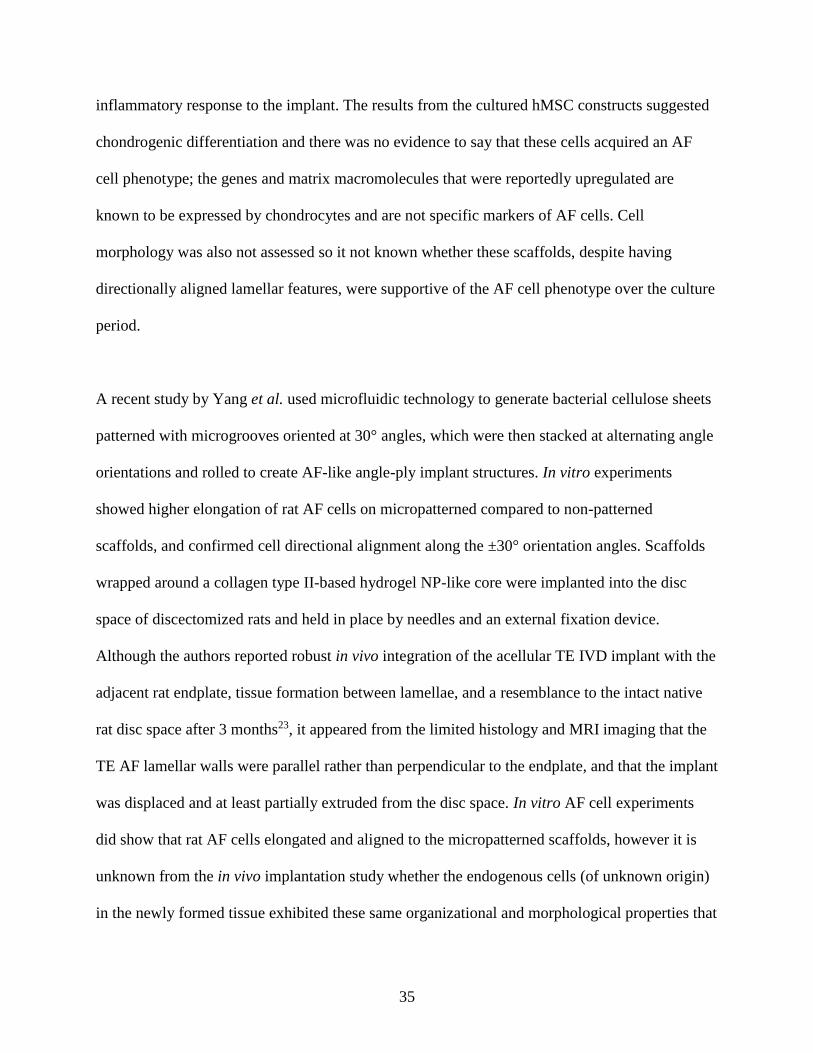
35
inflammatory response to the implant. The results from the cultured hMSC constructs suggested
chondrogenic differentiation and there was no evidence to say that these cells acquired an AF
cell phenotype; the genes and matrix macromolecules that were reportedly upregulated are
known to be expressed by chondrocytes and are not specific markers of AF cells. Cell
morphology was also not assessed so it not known whether these scaffolds, despite having
directionally aligned lamellar features, were supportive of the AF cell phenotype over the culture
period.
A recent study by Yang et al. used microfluidic technology to generate bacterial cellulose sheets
patterned with microgrooves oriented at 30° angles, which were then stacked at alternating angle
orientations and rolled to create AF-like angle-ply implant structures. In vitro experiments
showed higher elongation of rat AF cells on micropatterned compared to non-patterned
scaffolds, and confirmed cell directional alignment along the ±30° orientation angles. Scaffolds
wrapped around a collagen type II-based hydrogel NP-like core were implanted into the disc
space of discectomized rats and held in place by needles and an external fixation device.
Although the authors reported robust in vivo integration of the acellular TE IVD implant with the
adjacent rat endplate, tissue formation between lamellae, and a resemblance to the intact native
rat disc space after 3 months23, it appeared from the limited histology and MRI imaging that the
TE AF lamellar walls were parallel rather than perpendicular to the endplate, and that the implant
was displaced and at least partially extruded from the disc space. In vitro AF cell experiments
did show that rat AF cells elongated and aligned to the micropatterned scaffolds, however it is
unknown from the in vivo implantation study whether the endogenous cells (of unknown origin)
in the newly formed tissue exhibited these same organizational and morphological properties that
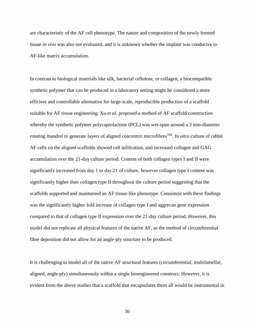
36
are characteristic of the AF cell phenotype. The nature and composition of the newly formed
tissue in vivo was also not evaluated, and it is unknown whether the implant was conducive to
AF-like matrix accumulation.
In contrast to biological materials like silk, bacterial cellulose, or collagen, a biocompatible
synthetic polymer that can be produced in a laboratory setting might be considered a more
efficient and controllable alternative for large-scale, reproducible production of a scaffold
suitable for AF tissue engineering. Xu et al. proposed a method of AF scaffold construction
whereby the synthetic polymer polycaprolactone (PCL) was wet-spun around a 3 mm-diameter
rotating mandrel to generate layers of aligned concentric microfibres168. In vitro culture of rabbit
AF cells on the aligned scaffolds showed cell infiltration, and increased collagen and GAG
accumulation over the 21-day culture period. Content of both collagen types I and II were
significantly increased from day 1 to day 21 of culture, however collagen type I content was
significantly higher than collagen type II throughout the culture period suggesting that the
scaffolds supported and maintained an AF tissue-like phenotype. Consistent with these findings
was the significantly higher fold increase of collagen type I and aggrecan gene expression
compared to that of collagen type II expression over the 21-day culture period. However, this
model did not replicate all physical features of the native AF, as the method of circumferential
fibre deposition did not allow for an angle-ply structure to be produced.
It is challenging to model all of the native AF structural features (circumferential, multilamellar,
aligned, angle-ply) simultaneously within a single bioengineered construct. However, it is
evident from the above studies that a scaffold that encapsulates them all would be instrumental in
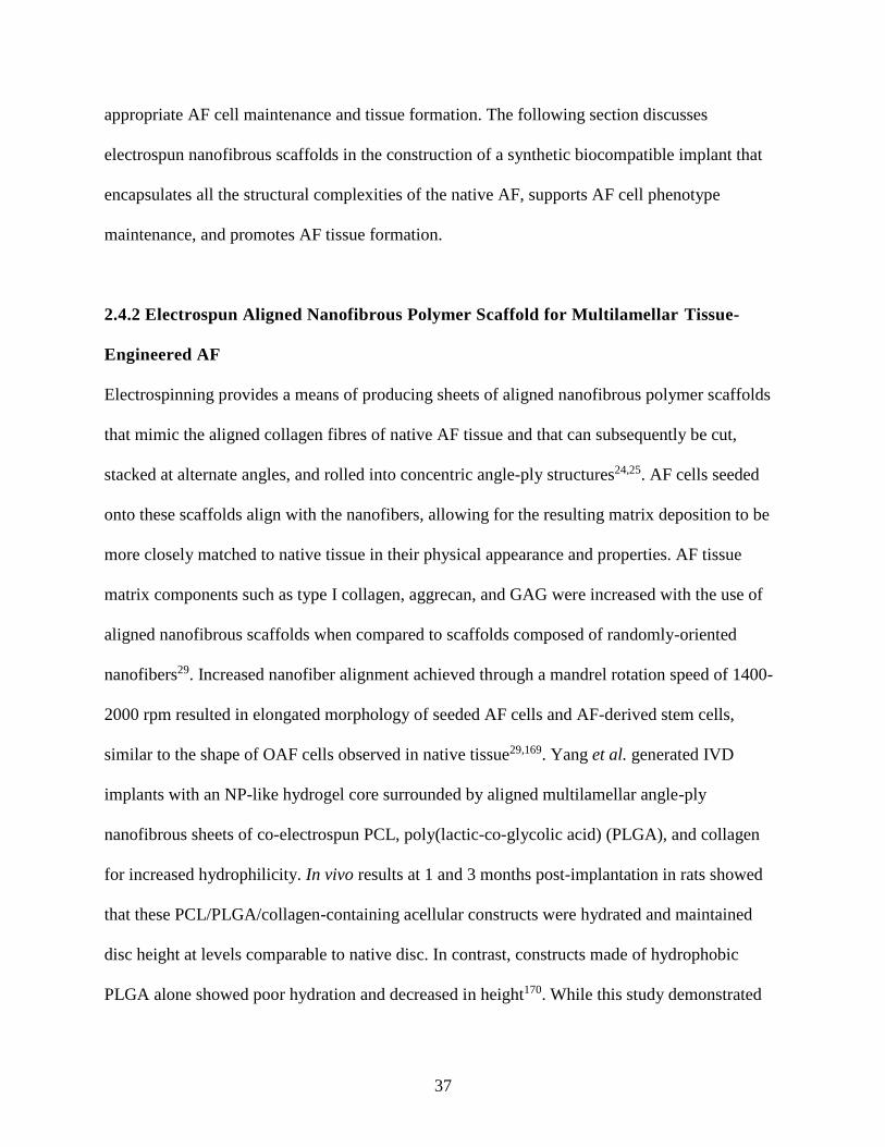
37
appropriate AF cell maintenance and tissue formation. The following section discusses
electrospun nanofibrous scaffolds in the construction of a synthetic biocompatible implant that
encapsulates all the structural complexities of the native AF, supports AF cell phenotype
maintenance, and promotes AF tissue formation.
2.4.2 Electrospun Aligned Nanofibrous Polymer Scaffold for Multilamellar Tissue-
Engineered AF
Electrospinning provides a means of producing sheets of aligned nanofibrous polymer scaffolds
that mimic the aligned collagen fibres of native AF tissue and that can subsequently be cut,
stacked at alternate angles, and rolled into concentric angle-ply structures24,25. AF cells seeded
onto these scaffolds align with the nanofibers, allowing for the resulting matrix deposition to be
more closely matched to native tissue in their physical appearance and properties. AF tissue
matrix components such as type I collagen, aggrecan, and GAG were increased with the use of
aligned nanofibrous scaffolds when compared to scaffolds composed of randomly-oriented
nanofibers29. Increased nanofiber alignment achieved through a mandrel rotation speed of 1400-
2000 rpm resulted in elongated morphology of seeded AF cells and AF-derived stem cells,
similar to the shape of OAF cells observed in native tissue29,169. Yang et al. generated IVD
implants with an NP-like hydrogel core surrounded by aligned multilamellar angle-ply
nanofibrous sheets of co-electrospun PCL, poly(lactic-co-glycolic acid) (PLGA), and collagen
for increased hydrophilicity. In vivo results at 1 and 3 months post-implantation in rats showed
that these PCL/PLGA/collagen-containing acellular constructs were hydrated and maintained
disc height at levels comparable to native disc. In contrast, constructs made of hydrophobic
PLGA alone showed poor hydration and decreased in height170. While this study demonstrated
38
the importance of an appropriately hydrophilic biomaterial for AF tissue-engineering, the
acellular nature of the construct was not demonstrative of a fully functionalized IVD implant.
Martin et al. developed an IVD model referred to as a Disc-like Angle Ply Structure (DAPS),
which was generated from electrospun PCL arranged in a multilamellar ±30° angle-ply
concentric structure26-28. Early work on the model determined that incorporation and subsequent
dissolution of a sacrificial polymer layer within electrospun PCL DAPS construct created
interlamellar spaces thereby improving cell infiltration in vitro26. DAPS made from electrospun
PCL strips alone were densely packed and showed poor infiltration of bovine AF cells in vitro
due to the tight spaces between scaffold layers. Acellular DAPS wrapped around a hyaluronic
acid (HA)-based hydrogel NP-like core were implanted into caudal rat spines27. Collagenous
matrix accumulation within the acellular DAPS implant was shown in vivo over the course of 12
weeks, however this process relied on endogenous cell infiltration. In comparison to an acellular
biomaterial implant which may also have poor endogenous cell infiltration in vivo, a cell-based
AF implant consisting of pre-formed engineered tissue might have improved compositional
characteristics and post-operational outcomes26,27. TE IVDs comprised of bovine AF cell-seeded
DAPS and NP cell-seeded HA hydrogel cores showed accumulation of GAG and collagen over a
15-week culture period in vitro, and were subsequently implanted into rat caudal spines28. This
study did not include a control experiment comparing the in vivo maturation of cell-seeded
DAPS implants to that of acellular implants, so it cannot be concluded from here that cell-seeded
implants perform with superiority in vivo. However, it was demonstrated that pre-seeded DAPS
accumulated ECM over time in vitro, thereby ensuring the presence of tissue upon implantation
and eliminating the reliance on endogenous cell infiltration.
39
Electrospun nanofibrous scaffolds for AF tissue generation have been made from various
polymers such as polylactic acid (PLA)171, PCL24,25,169,172,173, and polycarbonate-urethane
(PU)29,174,175. Electrospun nanofibers are smaller in diameter compared to microfibres, which
have previously been produced for AF construction by methods such as wet-spinning. Wet-
spinning of PCL showed that decreased microfiber diameter was achievable by increasing
mandrel rotation speed, however this resulted in fusion between microfibers, low scaffold
porosity, and consequently poor AF cell infiltration168. Smaller electrospun polymer fibre
diameter (≤ 1µm) improved human umbilical vein endothelial cell adhesion and promoted cell
elongation compared to larger fibre diameter (7 µm), on which seeded cells exhibited a rounder
morphology and low proliferation176. Electrospinning of PU for AF generation has produced
fibres with diameters of 200-400 nm177. PU in particular is a promising candidate for AF tissue
generation due to its tensile strength, elasticity, biocompatibility, and non-toxicity to AF cells177.
Although both aligned nanofibrous PCL and PU scaffolds seeded with AF cells produce ECM
that mimics the composition of native AF tissue, in comparison of both, PU has been found to
have better resistance to stretch and higher initial cell seeding efficiency178. Its initial modulus is
also tailored to be closer that of native ECM than the more crystalline PCL material.
Additionally, PLA forms acidic degradation products at concentrations that readily lower pH
levels and might lead to a decrease in ECM synthesis179,180. Increasing the surface energy of PU
scaffold by incorporating anionic dihydroxyl-oligomer (ADO) into the electrospun polymer was
found to increase scaffold hydrophilicity as indicated by a decreased water contact angle, and to
enhance AF cell attachment and collagen accumulation without significant cytotoxic
effects175,177. PU-ADO based polymer scaffold is particularly attractive for tissue engineering
40
purposes due to: (1) Its elastic properties and tensile strength; (2) its reproducibility, which
allows for reliable large-scale production; (3) its hydrophilic surface chemistry which mimics the
surface characteristics of proteins that are otherwise costly and that may have varying genetic
factors that cannot be controlled for; and (4) its biocompatible byproducts175,177. Iu et al. showed
that both IAF and OAF cells cultured separately on electrospun nanofibrous PU lamellar
scaffolds were able to maintain their respective phenotypes and produce appropriately distinct
ECM30,31.
2.4.3 Tissue-Engineered IVD-CEP Integration
One function of the native CEP is to provide a transitional substrate for IVD anchorage into the
underlying vertebral bone. There are currently few if any studies that have specifically generated
a cell-based tissue-engineered IVD-CEP interface model that contains a hyaline cartilage
component and that also recapitulates the structure of the aligned multilamellar AF. One in vitro
study by Tsai et al. incorporated an endplate component into an IVD model using human MSC-
derived osteoblasts induced to undergo chondrogenic differentiation, however the AF-endplate
interface itself was not the main focus of the study and was not characterized40.
Implantation studies have examined the performance of nanofibrous TE AF construct
implantation in rats, however these acellular implants relied on the slow processes of post-
operative endogenous cell infiltration and in vivo tissue integration26,27,170. Martin and colleagues
acknowledged that while implantation of an acellular DAPS into rat caudal spines showed
endogenous cell infiltration, integration with adjacent vertebrae did not occur and implant
extrusion from the disc space was evident by 12 weeks27. Poor integration and extrusion of a
41
cell-seeded DAPS implant from the intervertebral space also occurred28. Cell-seeded DAPS 5
weeks post-implantation displayed proteoglycan loss, lack of integration with adjacent vertebrae,
and extrusion from the disc space regardless of either a 5 or 10 week pre-culture period28. This
was an indication that tissue integration must be considered going forward in the development of
a feasible bioengineered IVD implant. Subsequently, an acellular porous polymer endplate
component allowing for bony ingrowth was incorporated into the implant model in an attempt to
facilitate integration and generate mechanical continuity along the vertebra28. The engineered
endplates appeared to mitigate the loss of proteoglycan and improved integration with adjacent
vertebrae after implantation, which emphasized the importance of having integrated components,
particularly endplates, in an IVD implant model. However, the cartilaginous layer that lies
between the IVD and the bony endplate within the native disc space, which is in itself essential
for disc-vertebra anchorage and integration, was disregarded in this DAPS-endplate model. The
distributions of collagen types I and II were also diffuse and not distinctly localized within the
DAPS in vitro, thus the engineered AF did not have distinct inner or outer regions28. To resolve
these issues that arise from the innate complexity of the native IVD, a more complete implant
model would require distinct IAF and OAF regions, as well as an integrated CEP layer that
would further be able to integrate with bone.
Inclusion of a cartilaginous endplate component is desired for a more complete IVD implant
model; however, without a pre-formed IVD-CEP interface prior to implantation, appropriate
tissue integration in vivo might be difficult and slow. For example, integration of cell-seeded
collagen gel AF-NP constructs with native rat endplate showed discontinuities 6 weeks after
implantation, and continuous integration did not occur until 6 months post-operatively154.
42
Integration of tissue-engineered AF constructs specifically with an engineered CEP has not been
an area of focus in current literature. Integration of engineered disc and cartilage tissues prior to
implantation might be a solution to circumvent poor implant integration in vivo. However,
culture times may be long, and sub-optimal in vitro conditions might not allow for maximal
integration potential. Therefore, it would be of great use to determine applicable treatments that
would be able to enhance or accelerate the integration process in vitro. Mechanical stimulation is
one method that has been shown to be of potential use for the enhancement of tissue matrix
accumulation and mechanical properties.
2.5 The Role of Mechanical Stimulation on Extracellular Matrix Composition
It has been shown that in IVD tissue, IVD cells, tissue-engineered IVDs, and tissue-engineered
cartilage, certain frequencies and amplitudes of dynamic tensile and compressive strain can have
anabolic effects on matrix components by stimulating protein and gene expression, and may play
a role in reducing matrix protein degradation32-42. Table 1 summarizes the findings of the current
literature on compressive, tensile, and static loading on IVD and cartilage cells and tissue.
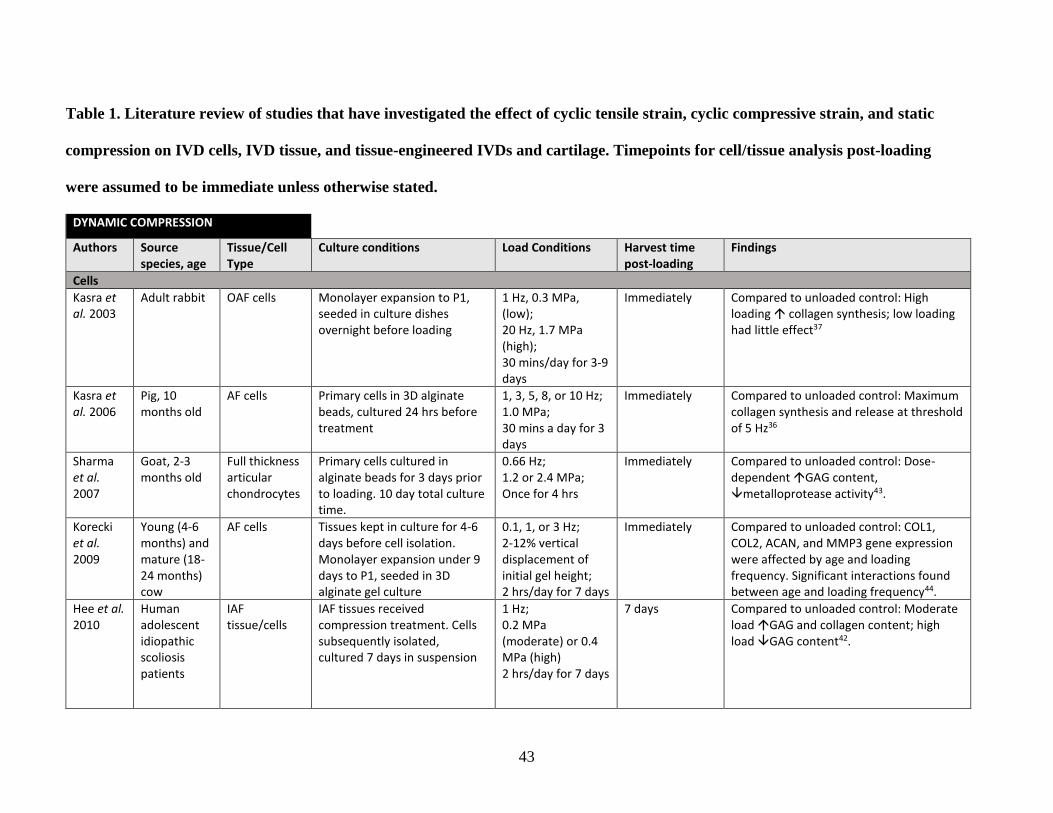
43
Table 1. Literature review of studies that have investigated the effect of cyclic tensile strain, cyclic compressive strain, and static
compression on IVD cells, IVD tissue, and tissue-engineered IVDs and cartilage. Timepoints for cell/tissue analysis post-loading
were assumed to be immediate unless otherwise stated.
DYNAMIC COMPRESSION
Authors Source species, age
Tissue/Cell Type
Culture conditions Load Conditions Harvest time post-loading
Findings
Cells
Kasra et al. 2003
Adult rabbit OAF cells Monolayer expansion to P1, seeded in culture dishes overnight before loading
1 Hz, 0.3 MPa, (low); 20 Hz, 1.7 MPa (high); 30 mins/day for 3-9 days
Immediately Compared to unloaded control: High loading collagen synthesis; low loading had little effect37
Kasra et al. 2006
Pig, 10 months old
AF cells Primary cells in 3D alginate beads, cultured 24 hrs before treatment
1, 3, 5, 8, or 10 Hz; 1.0 MPa; 30 mins a day for 3 days
Immediately Compared to unloaded control: Maximum collagen synthesis and release at threshold of 5 Hz36
Sharma et al. 2007
Goat, 2-3 months old
Full thickness articular chondrocytes
Primary cells cultured in alginate beads for 3 days prior to loading. 10 day total culture time.
0.66 Hz; 1.2 or 2.4 MPa; Once for 4 hrs
Immediately Compared to unloaded control: Dose-dependent GAG content, metalloprotease activity43.
Korecki et al. 2009
Young (4-6 months) and mature (18-24 months) cow
AF cells Tissues kept in culture for 4-6 days before cell isolation. Monolayer expansion under 9 days to P1, seeded in 3D alginate gel culture
0.1, 1, or 3 Hz; 2-12% vertical displacement of initial gel height; 2 hrs/day for 7 days
Immediately Compared to unloaded control: COL1, COL2, ACAN, and MMP3 gene expression were affected by age and loading frequency. Significant interactions found between age and loading frequency44.
Hee et al. 2010
Human adolescent idiopathic scoliosis patients
IAF tissue/cells
IAF tissues received compression treatment. Cells subsequently isolated, cultured 7 days in suspension
1 Hz; 0.2 MPa (moderate) or 0.4 MPa (high) 2 hrs/day for 7 days
7 days Compared to unloaded control: Moderate load GAG and collagen content; high load GAG content42.
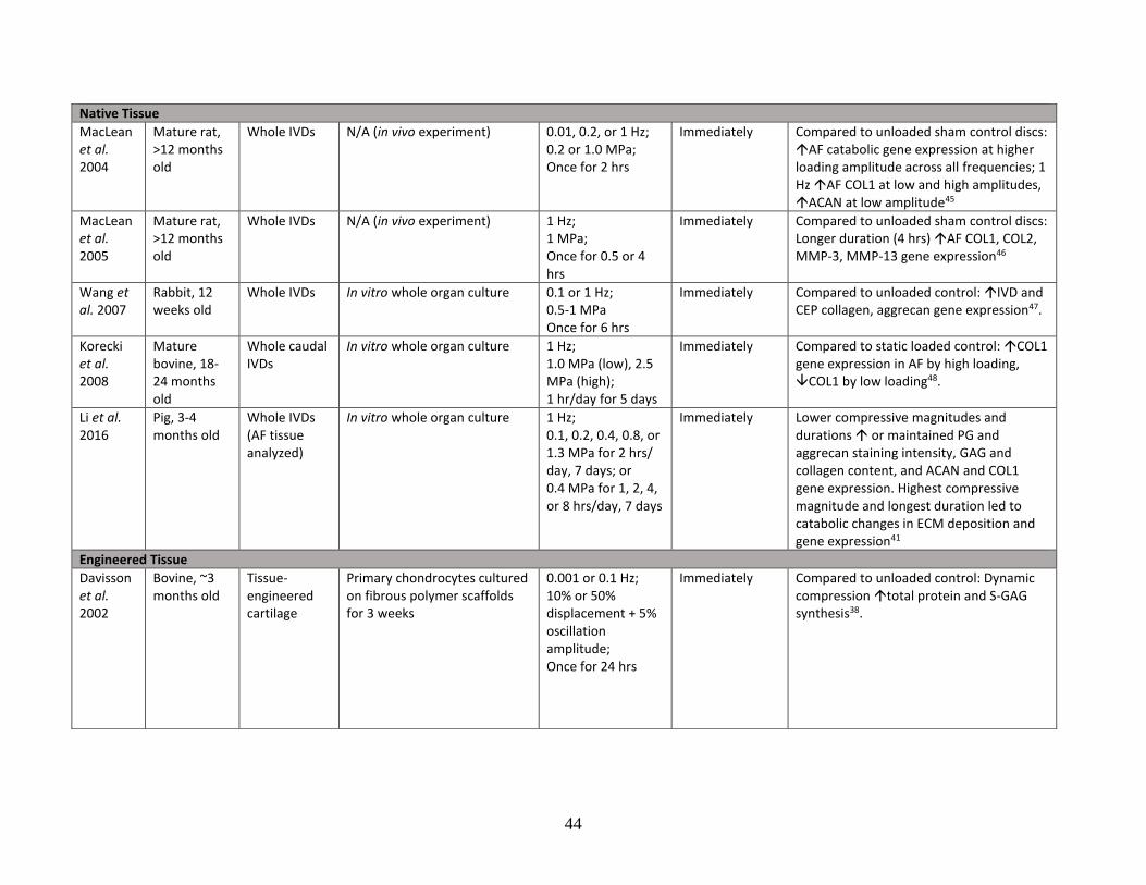
44
Native Tissue
MacLean et al. 2004
Mature rat, >12 months old
Whole IVDs N/A (in vivo experiment) 0.01, 0.2, or 1 Hz; 0.2 or 1.0 MPa; Once for 2 hrs
Immediately Compared to unloaded sham control discs: AF catabolic gene expression at higher loading amplitude across all frequencies; 1 Hz AF COL1 at low and high amplitudes, ACAN at low amplitude45
MacLean et al. 2005
Mature rat, >12 months old
Whole IVDs N/A (in vivo experiment) 1 Hz; 1 MPa; Once for 0.5 or 4 hrs
Immediately Compared to unloaded sham control discs: Longer duration (4 hrs) AF COL1, COL2, MMP-3, MMP-13 gene expression46
Wang et al. 2007
Rabbit, 12 weeks old
Whole IVDs In vitro whole organ culture 0.1 or 1 Hz; 0.5-1 MPa Once for 6 hrs
Immediately Compared to unloaded control: IVD and CEP collagen, aggrecan gene expression47.
Korecki et al. 2008
Mature bovine, 18-24 months old
Whole caudal IVDs
In vitro whole organ culture 1 Hz; 1.0 MPa (low), 2.5 MPa (high); 1 hr/day for 5 days
Immediately Compared to static loaded control: COL1 gene expression in AF by high loading, COL1 by low loading48.
Li et al. 2016
Pig, 3-4 months old
Whole IVDs (AF tissue analyzed)
In vitro whole organ culture 1 Hz; 0.1, 0.2, 0.4, 0.8, or 1.3 MPa for 2 hrs/ day, 7 days; or 0.4 MPa for 1, 2, 4, or 8 hrs/day, 7 days
Immediately Lower compressive magnitudes and durations or maintained PG and aggrecan staining intensity, GAG and collagen content, and ACAN and COL1 gene expression. Highest compressive magnitude and longest duration led to catabolic changes in ECM deposition and gene expression41
Engineered Tissue
Davisson et al. 2002
Bovine, ~3 months old
Tissue-engineered cartilage
Primary chondrocytes cultured on fibrous polymer scaffolds for 3 weeks
0.001 or 0.1 Hz; 10% or 50% displacement + 5% oscillation amplitude; Once for 24 hrs
Immediately Compared to unloaded control: Dynamic compression total protein and S-GAG synthesis38.
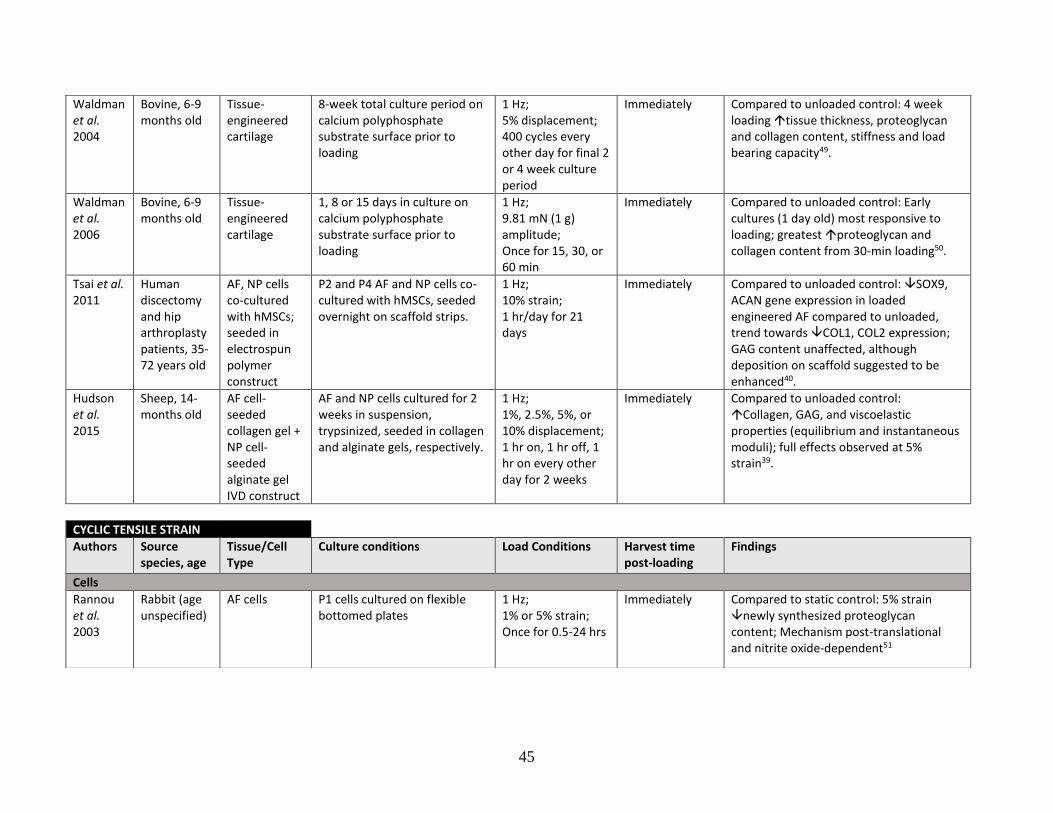
45
Waldman et al. 2004
Bovine, 6-9 months old
Tissue-engineered cartilage
8-week total culture period on calcium polyphosphate substrate surface prior to loading
1 Hz; 5% displacement; 400 cycles every other day for final 2 or 4 week culture period
Immediately Compared to unloaded control: 4 week loading tissue thickness, proteoglycan and collagen content, stiffness and load bearing capacity49.
Waldman et al. 2006
Bovine, 6-9 months old
Tissue-engineered cartilage
1, 8 or 15 days in culture on calcium polyphosphate substrate surface prior to loading
1 Hz; 9.81 mN (1 g) amplitude; Once for 15, 30, or 60 min
Immediately Compared to unloaded control: Early cultures (1 day old) most responsive to loading; greatest proteoglycan and collagen content from 30-min loading50.
Tsai et al. 2011
Human discectomy and hip arthroplasty patients, 35-72 years old
AF, NP cells co-cultured with hMSCs; seeded in electrospun polymer construct
P2 and P4 AF and NP cells co-cultured with hMSCs, seeded overnight on scaffold strips.
1 Hz; 10% strain; 1 hr/day for 21 days
Immediately Compared to unloaded control: SOX9, ACAN gene expression in loaded engineered AF compared to unloaded, trend towards COL1, COL2 expression; GAG content unaffected, although deposition on scaffold suggested to be enhanced40.
Hudson et al. 2015
Sheep, 14-months old
AF cell-seeded collagen gel + NP cell-seeded alginate gel IVD construct
AF and NP cells cultured for 2 weeks in suspension, trypsinized, seeded in collagen and alginate gels, respectively.
1 Hz; 1%, 2.5%, 5%, or 10% displacement; 1 hr on, 1 hr off, 1 hr on every other day for 2 weeks
Immediately Compared to unloaded control: Collagen, GAG, and viscoelastic properties (equilibrium and instantaneous moduli); full effects observed at 5% strain39.
CYCLIC TENSILE STRAIN
Authors Source species, age
Tissue/Cell Type
Culture conditions Load Conditions Harvest time post-loading
Findings
Cells
Rannou et al. 2003
Rabbit (age unspecified)
AF cells P1 cells cultured on flexible bottomed plates
1 Hz; 1% or 5% strain; Once for 0.5-24 hrs
Immediately Compared to static control: 5% strain newly synthesized proteoglycan content; Mechanism post-translational and nitrite oxide-dependent51
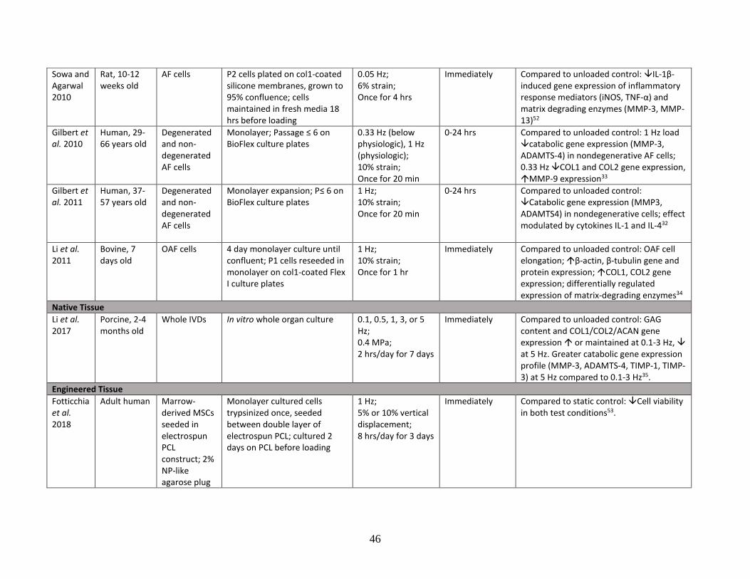
46
Sowa and Agarwal 2010
Rat, 10-12 weeks old
AF cells P2 cells plated on col1-coated silicone membranes, grown to 95% confluence; cells maintained in fresh media 18 hrs before loading
0.05 Hz; 6% strain; Once for 4 hrs
Immediately Compared to unloaded control: IL-1β-induced gene expression of inflammatory response mediators (iNOS, TNF-α) and matrix degrading enzymes (MMP-3, MMP-13)52
Gilbert et al. 2010
Human, 29-66 years old
Degenerated and non-degenerated AF cells
Monolayer; Passage ≤ 6 on BioFlex culture plates
0.33 Hz (below physiologic), 1 Hz (physiologic); 10% strain; Once for 20 min
0-24 hrs Compared to unloaded control: 1 Hz load catabolic gene expression (MMP-3, ADAMTS-4) in nondegenerative AF cells; 0.33 Hz COL1 and COL2 gene expression, MMP-9 expression33
Gilbert et al. 2011
Human, 37-57 years old
Degenerated and non-degenerated AF cells
Monolayer expansion; P≤ 6 on BioFlex culture plates
1 Hz; 10% strain; Once for 20 min
0-24 hrs Compared to unloaded control: Catabolic gene expression (MMP3, ADAMTS4) in nondegenerative cells; effect modulated by cytokines IL-1 and IL-432
Li et al. 2011
Bovine, 7 days old
OAF cells 4 day monolayer culture until confluent; P1 cells reseeded in monolayer on col1-coated Flex I culture plates
1 Hz; 10% strain; Once for 1 hr
Immediately Compared to unloaded control: OAF cell elongation; β-actin, β-tubulin gene and protein expression; COL1, COL2 gene expression; differentially regulated expression of matrix-degrading enzymes34
Native Tissue
Li et al. 2017
Porcine, 2-4 months old
Whole IVDs In vitro whole organ culture 0.1, 0.5, 1, 3, or 5 Hz; 0.4 MPa; 2 hrs/day for 7 days
Immediately Compared to unloaded control: GAG content and COL1/COL2/ACAN gene expression or maintained at 0.1-3 Hz, at 5 Hz. Greater catabolic gene expression profile (MMP-3, ADAMTS-4, TIMP-1, TIMP-3) at 5 Hz compared to 0.1-3 Hz35.
Engineered Tissue
Fotticchia et al. 2018
Adult human Marrow-derived MSCs seeded in electrospun PCL construct; 2% NP-like agarose plug
Monolayer cultured cells trypsinized once, seeded between double layer of electrospun PCL; cultured 2 days on PCL before loading
1 Hz; 5% or 10% vertical displacement; 8 hrs/day for 3 days
Immediately Compared to static control: Cell viability in both test conditions53.
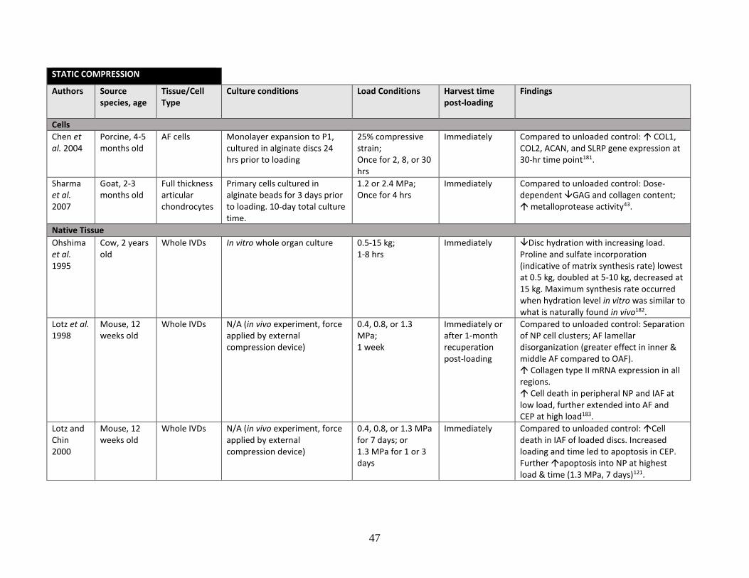
47
STATIC COMPRESSION
Authors Source species, age
Tissue/Cell Type
Culture conditions Load Conditions Harvest time post-loading
Findings
Cells
Chen et al. 2004
Porcine, 4-5 months old
AF cells Monolayer expansion to P1, cultured in alginate discs 24 hrs prior to loading
25% compressive strain; Once for 2, 8, or 30 hrs
Immediately Compared to unloaded control: COL1, COL2, ACAN, and SLRP gene expression at 30-hr time point181.
Sharma et al. 2007
Goat, 2-3 months old
Full thickness articular chondrocytes
Primary cells cultured in alginate beads for 3 days prior to loading. 10-day total culture time.
1.2 or 2.4 MPa; Once for 4 hrs
Immediately Compared to unloaded control: Dose-dependent GAG and collagen content; metalloprotease activity43.
Native Tissue
Ohshima et al. 1995
Cow, 2 years old
Whole IVDs In vitro whole organ culture 0.5-15 kg; 1-8 hrs
Immediately Disc hydration with increasing load. Proline and sulfate incorporation (indicative of matrix synthesis rate) lowest at 0.5 kg, doubled at 5-10 kg, decreased at 15 kg. Maximum synthesis rate occurred when hydration level in vitro was similar to what is naturally found in vivo182.
Lotz et al. 1998
Mouse, 12 weeks old
Whole IVDs N/A (in vivo experiment, force applied by external compression device)
0.4, 0.8, or 1.3 MPa; 1 week
Immediately or after 1-month recuperation post-loading
Compared to unloaded control: Separation of NP cell clusters; AF lamellar disorganization (greater effect in inner & middle AF compared to OAF). Collagen type II mRNA expression in all regions. Cell death in peripheral NP and IAF at low load, further extended into AF and CEP at high load183.
Lotz and Chin 2000
Mouse, 12 weeks old
Whole IVDs N/A (in vivo experiment, force applied by external compression device)
0.4, 0.8, or 1.3 MPa for 7 days; or 1.3 MPa for 1 or 3 days
Immediately Compared to unloaded control: Cell death in IAF of loaded discs. Increased loading and time led to apoptosis in CEP. Further apoptosis into NP at highest load & time (1.3 MPa, 7 days)121.
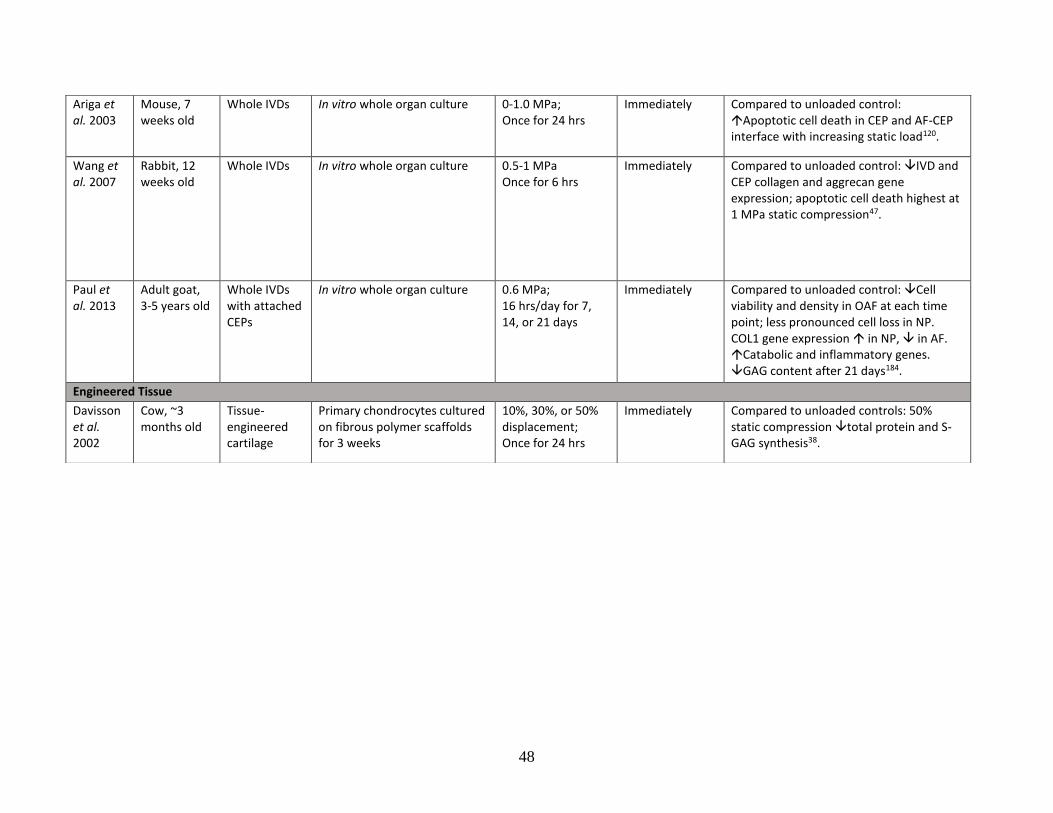
48
Ariga et al. 2003
Mouse, 7 weeks old
Whole IVDs In vitro whole organ culture 0-1.0 MPa; Once for 24 hrs
Immediately Compared to unloaded control: Apoptotic cell death in CEP and AF-CEP interface with increasing static load120.
Wang et al. 2007
Rabbit, 12 weeks old
Whole IVDs In vitro whole organ culture 0.5-1 MPa Once for 6 hrs
Immediately Compared to unloaded control: IVD and CEP collagen and aggrecan gene expression; apoptotic cell death highest at 1 MPa static compression47.
Paul et al. 2013
Adult goat, 3-5 years old
Whole IVDs with attached CEPs
In vitro whole organ culture 0.6 MPa; 16 hrs/day for 7, 14, or 21 days
Immediately Compared to unloaded control: Cell viability and density in OAF at each time point; less pronounced cell loss in NP. COL1 gene expression in NP, in AF. Catabolic and inflammatory genes. GAG content after 21 days184.
Engineered Tissue
Davisson et al. 2002
Cow, ~3 months old
Tissue-engineered cartilage
Primary chondrocytes cultured on fibrous polymer scaffolds for 3 weeks
10%, 30%, or 50% displacement; Once for 24 hrs
Immediately Compared to unloaded controls: 50% static compression total protein and S-GAG synthesis38.
49
Cyclic tensile strain applied to AF cells at 1 Hz has been shown to decrease catabolic gene
expression, upregulate collagen gene expression, and have a role in proteoglycan production
modulation32-34,51. Compared to uncompressed controls, dynamic compression of immature
porcine IVDs at low frequencies of 0.1-3 Hz maintained or promoted ECM synthesis, while
compression at a relatively higher frequency of 5 Hz led to decreased ECM molecule
accumulation and increased catabolic gene expression35. Similarly, a study on the dynamic
compression of porcine IVD cells in 3D culture found that among uncompressed controls and
discs under loading frequencies of 1-10 Hz, decreased collagen synthesis and maximum collagen
degradation occurred at a frequency threshold of 5 Hz36. It is suggested that a loading frequency
of 0.1–1 Hz provides a “physiologic” range by which dynamic mechanical loading may be
favourable for IVD matrix stimulation and repair185. Frequencies below the physiologic value of
1 Hz may cause a shift towards matrix catabolism33.
In addition to compressive frequency, matrix accumulation appears to be dependent on
compressive magnitude and duration. Hee et al. found that a moderate level of 0.2 MPa dynamic
compression increased human AF and NP collagen and GAG content compared to uncompressed
control cells, whereas a higher compression magnitude of 0.4 MPa decreased content42. In
contrast, Kasra et al. found that high dynamic loading amplitude and frequency (1.7 MPa, 20 Hz)
led to greater collagen synthesis in rabbit OAF cells compared to unloaded cells, while low
amplitude and frequency (0.3 MPa, 1 Hz) had little effect37. However, it was not possible from
the study design to determine whether the apparent effect on collagen synthesis was due to
loading amplitude or loading frequency. Maclean et al. found that catabolic gene expression in
the AF of an in vivo rat model was upregulated across all loading frequencies (0.01–1 Hz) when
50
compared to sham controls, but only by the higher loading magnitude tested (1.0 MPa)
suggesting that AF matrix metabolism may be more dependant on compressive magnitude rather
than frequency45. The same research group found that in comparison to 30-minute dynamic
compression, a longer duration of 4 hours significantly upregulated gene expression of collagen
type I, collagen type II, MMP-3, and MMP-13 in the AF compared to unloaded sham controls46.
Li et al. demonstrated that prolonged dynamic compressive stimulation for 8 hours led to
catabolic changes in matrix deposition and gene expression in comparison to uncompressed
controls, while stimulation between 1 and 4 hours had anabolic effects41. There may therefore be
a duration threshold that is optimal for matrix synthesis and/or maintenance.
In contrast to dynamic compression, static compression has been shown to predominantly have
catabolic effects on matrix molecules38. Static mechanical loading of IVD explants has been
found to lead to CEP chondrocyte apoptosis, which may further contribute to IVD
degeneration120. Acute ex vivo vibratory stimulation of IVDs transiently increased anabolic gene
expression and matrix molecule accumulation, however repeated long-term vibration-type
stimulation interestingly resulted in degenerative changes186-188.
There is a gap in the current literature regarding the effect of dynamic loading on nanofibrous
angle-ply multilamellar electrospun constructs seeded with AF cells. Two studies have
investigated the effect of dynamic mechanical loading on cell-seeded electrospun IVD models,
however the conclusions that can be drawn from them are perhaps limited due to their use of
MSCs40,53. Fotticchia et al. recently showed that in comparison to static control conditions,
dynamic tensile strain of a double layered AF-like electrospun PCL-based construct decreased
51
cell viability of seeded human bone marrow-derived MCSs. The AF construct was wrapped in an
angle-ply fashion around a central NP-like agarose plug, which was then subjected to 5% or 10%
dynamic vertical displacement. In this design, the radial stress exerted from the agarose plug
transferred into circumferential stress in the AF layer, thus causing the electrospun cell-seeded
fibres experience tensile strain. Sinusoidal compression was applied at 8 hours a day for 3 days
and was found to decrease cell viability at both amplitude conditions, suggesting that dynamic
mechanical stimulation may be detrimental to an angle-ply, lamellar IVD construct53. However,
it must be noted that dynamic compression was applied to the constructs only 2 days after initial
cell seeding. The purpose of engineering a scaffold-based IVD is to form tissue, and 2 days may
not be sufficient time for cells to form substantial tissue. Had the cell-seeded constructs been
given time to form tissue over a longer culture period, results may have differed. The 8-hour
application time was also excessive compared to other studies (see Table 1), and was previously
found to lead to catabolic changes in whole IVDs41. Additionally, the reduced cell viability in
response to cyclic compression may have been related to the fact that marrow-derived MSCs do
not normally experience the same types of forces that AF cells experience in the spine.
Tsai et al. also applied dynamic compression to engineered IVDs composed of electrospun
PLA/PCL angle-ply layers seeded with AF cells and MSCs, and a central NP-like synthetic
hydrogel matrix (PuraMatrix) seeded with NP cells and MSCs. An “optimal ratio” of co-cultured
human AF or NP cells and human MSCs was determined by gene expression analyses and
seeded in their respective scaffolds. Dynamic compression of these constructs was suggested to
promote homogenous cell and matrix distribution within the scaffolds. It was also suggested
from gene expression analyses that dynamic loading inhibited the differentiation of MSCs
52
towards hyaline chondrogenesis and promoted fibrochondrocyte (AF-like) differentiation40.
However, they did not provide convincing evidence of anabolic effects on the AF ECM through
their histology images, and immunohistochemistry to identify specific matrix molecule
accumulation was not performed. In addition to evaluating the effect of dynamic loading, the
difficulty of co-culturing AF cells and MSCs in an appropriate culture medium to induce an AF-
like phenotype added further complexity to the system. Investigation of dynamic compression on
an electrospun angle-ply multilamellar construct cultured with AF cells alone would provide a
more reflective determination its effectiveness for promoting AF tissue growth, and would fill
the gap in the literature.
The current literature demonstrates that the effects of dynamic mechanical stimulation on matrix
maintenance and synthesis are dependent on a complex set of parameters. The IVD in vivo is
constantly under mechanical load, however the role of dynamic compression in the formation,
maintenance, and mechanical strength of the specialized AF-CEP interface is unknown.
Development of a bioengineered nanofibrous scaffold-based AF-CEP model and placing it under
mechanical stimulation will help in furthering this understanding.
53
CHAPTER 3: DEVELOPMENT OF AN IN VITRO OUTER
ANNULUS FIBROSUS-CARTILAGE ENDPLATE MODEL AND
ITS RESPONSE TO DYNAMIC MECHANICAL LOADING
3.1 Introduction
Back pain is a chronic condition that presents direct healthcare costs estimated to exceed 20
billion dollars per year in the United States alone189. It is associated with degenerative disc
disease (DDD) and pathologic changes in the vertebral cartilage endplate5,126,190,191. Degenerative
processes in these tissues are irreversible due to their inherent lack of regenerative capacity192.
Conservative treatments for DDD-related back pain such as physical therapy and pain
medication do not target the underlying degenerative pathologies. Surgical interventions include
discectomy, fusion of vertebral segments, or prosthetic disc replacements; however, these
treatments do not guarantee long-term pain relief and may lead to further complications such as
adjacent segment degeneration8,129. Current research is focused on investigating and ultimately
implementing a cell-based tissue-engineered implant solution that replaces the degenerate native
IVD thereby restoring function, and minimizing further degeneration in adjacent discs193.
The intervertebral disc (IVD) consists of a central nucleus pulposus (NP) and a surrounding
annulus fibrosus (AF). Hyaline cartilage endplates (CEP) are located on the cranial and caudal
aspects of each disc. The IVD is a relatively avascular tissue that is contained in a low oxygen
environment. It obtains nutrients primarily via diffusion from small blood vessels that extend
from the vertebral bone marrow into the hyaline portion of the CEP, and from vessels that are
located at the periphery of the AF2,4,54. It is a tissue of relatively low cellularity; the average cell
54
density of the human IVD has been reported to be ~6000 cells/mm3, approximately 2.5 times
lower than that of articular cartilage which in itself is known to be a tissue of low cellularity2.
While the NP is gel-like and does not possess a high level of organization, the AF is a
multilamellar angle-ply structure that is further organized into inner and outer regions, each
having their own distinct composition. The collagen fibres within successive AF lamellae are
alternately oriented at ±30° angles with respect to the vertical axis89. The main collagens of the
IVD are the fibrillar collagen types I and II, which provide tensile strength and compressive
resistance respectively58. The outer AF (OAF) is composed of highly aligned collagen type I
fibres and elongated fibroblast-like cells. The inner AF (IAF) is less organized and composed of
collagen type I, collagen type II, proteoglycans, and rounded cells7,90. Proteoglycan content of
the IVD is highest within the NP and lowest in the OAF, with percent water content generally
following the same trend56. The main proteoglycan found in the IVD and CEP is aggrecan,
which is similar to collagen type II in its regional distribution and in its role to provide
compressive resistance64. The CEP is the site of attachment and mechanical load transfer
between the relatively soft IVD fibres and stiff vertebral bone (VB)1,100-102. A layer of calcified
cartilage within the CEP lies adjacent to the VB, which serves to provide further anchorage of
the disc into the bone1,63. AF fibres insert into the CEP and also curve laterally around it at the
periphery63. With increasing age, the hyaline CEP becomes mineralized in the region between
the OAF and vertebral rim99. Tissue engineering of this interface remains a key challenge in
establishing a functional biological disc replacement.
Tissue-engineered cell-based IVD models that have been developed to date have included AF
and NP components only, and have lacked any in vitro-formed CEP-like cartilage tissue
55
components20,154-157,194. Concentric multilamellar angle-ply structures have successfully been
generated to mimic the complexity of the AF using biomaterials such as silk fibroin22,161,
bacterial cellulose23, and electrospun nanofibrous polymer scaffolds24,25,27,28,31,169,170,195. Tissue-
engineered NP-like hydrogel and scaffold components have been generated from biomaterials
such as polysaccharide, glycosaminoglycan, collagen, and synthetic
polymers20,21,27,28,39,154,155,157,160,170. Both acellular20,27,170 and cell-seeded tissue engineered NP-
like cores21,28,39,160,194 have been used in the generation of biphasic AF-NP constructs. However,
to the best of our knowledge, there are no studies describing the generation of an integrated cell-
based IVD-CEP interface model. The importance of integrated tissues within an engineered IVD
implant model was demonstrated by Martin et al. who implanted a multilamellar angle-ply AF
structure into rat spines, and found that the implant extruded from the disc space due to a lack of
appropriate stabilization between the native vertebral bodies28. Subsequent incorporation of an
acellular porous polymer endplate at the ends of the angle-ply structure improved the integration
of the implant within the native disc space28, however this model lacked a cartilaginous layer to
accurately mimic what is seen in the native AF-VB region63. The CEP, which is in itself essential
for AF fibre anchorage into the native VB, should be included in an implant model in order to
establish proper biomechanics during loading, to facilitate nutritional diffusion, and to mimic the
integration of tissues that naturally occurs in vivo. Integration of in vitro-generated tissues upon
implantation in vivo has been shown to be difficult and slow; integration of cell-seeded collagen
gel AF-NP constructs with native rat endplate showed discontinuities 6 weeks after implantation,
and continuous integration did not occur until 6 months post-operatively154. Therefore,
generation of an IVD-CEP interface in vitro prior to implantation might be a way to circumvent
poor in vivo integration during the post-implantation period.
56
In a previous study, an optimized AF tissue culture system was developed whereby distinct and
robust IAF and OAF tissues were generated using a single culture medium cocktail31. IAF and
OAF cells seeded separately on aligned nanofibrous polycarbonate urethane-anionic dihydroxyl
oligomer (PU-ADO) scaffolds maintained their respective phenotypes when cultured in DMEM
media supplemented with fetal bovine serum, insulin-transferrin-selenium (ITS), proline,
dexamethasone and pyruvate31. Additional work has also validated a 3-dimensional (3D) culture
method to generate in vitro hyaline cartilage from primary chondrocytes196. Having these two
tissues will allow for the development of a co-culture model to address the issue of tissue
integration. Furthermore, it will facilitate investigations into the effect of dynamic loading as a
potential treatment to enhance integration between bioengineered interfacial IVD tissues.
Thus the hypothesis of this study was that the placement of in vitro OAF tissue formed on
aligned nanofibrous multi-lamellated PU-ADO scaffolds in direct-contact and co-culture with in
vitro-generated cartilage tissue formed in 3D culture will generate an integrated interface
containing extracellular matrix (ECM) that resembles native OAF-CEP. Additionally, it was
hypothesized that this interface can be mechanically and compositionally enhanced through
dynamic compressive loading.
3.2 Methods
3.2.1 Isolation of OAF cells
Intervertebral discs were aseptically excised from 6-9-month old bovine caudal spines within 4
hours of death and placed in Ham’s F12 media. OAF was isolated from the rest of the disc and
57
fine-diced. Tissues were enzymatically digested in 0.3% protease (P5147, Sigma) for 1 hour at
37°C, followed by 0.2% collagenase A (COLLA-RO, Roche Diagnostics) overnight at 37°C.
Cells from digested tissue were filtered through a cell strainer and centrifuged at 600 RCF for 8
minutes. Cell pellets were washed 3 times in Dulbecco's modification Eagle's medium (DMEM;
4.5 g/L glucose; Multicell) supplemented with 5% fetal bovine serum (FBS; Multicell). Viable
OAF cells were counted by staining with trypan blue and a hemocytometer, and re-suspended in
DMEM supplemented with 5% FBS at a density of 1.6 x 10⁶ cells/mL (Figure 3.1.A).
3.2.2 Generation of aligned nanofibrous PU-ADO scaffold constructs
Anionic dihydroxyl oligomer (ADO) and polycarbonate urethane (PU) were synthesized as
described previously175. Briefly, in a 20 mL glass scintillation vial, ADO was added to PU at a
concentration of 0.15% by dry weight of PU. 1,1,1,3,3,3-hexafluoro-2-propanol (105228,
Aldrich) was added to yield 18% concentration by dry weight of PU-ADO to volume of solvent.
The solution was sealed tightly, protected from light and allowed to fully dissolve overnight in a
rotator at room temperature. Viscosity was standardized by allowing the solution to flow out of a
1 mL syringe (plunger removed) fitted with a blunt fill 18G x 1½” needle, and ensuring that the
time taken for the volume to decrease from 0.7 mL to 0.6 mL was 73 seconds across
formulations. Viscosity was adjusted if necessary, by either adding more solvent or by allowing
the solution to evaporate under a fume hood.
PU-ADO aligned nanofibrous scaffolds were produced by electrospinning for 8 hours onto a
1150 rpm rotating mandrel, with an applied potential difference of 17kV at an infuse rate of 0.5
mL/hr. The scaffold was cured in an Isotemp Vacuum Oven (Model 281A, Fisher Scientific)
58
overnight at 45°C. Nanofibers were imaged using scanning electron microscopy and structural
alignment was quantified using Fast Fourier Transformation analysis on ImageJ software197.
Scaffold sheets were cut into 3mm x 50mm strips at a 30° angle relative to nanofiber direction,
and sterilized by gamma irradiation (2.5 Mrad) (Supplemental Figure S2).
Irradiated scaffold strips were soaked in 10 µg/mL fibronectin (f1141, Sigma-Aldrich) in sterile
phosphate buffered saline without Ca2+ or Mg2+ (PBS-/-; Multicell) overnight at 37.5°C. Two
fibronectin-coated strips with opposing fibre angle orientation were stacked and rolled around
TYGON 3350 silicone tubing (4 mm outer diameter, Saint-Gobain) to create 6-layered
concentric constructs. Eight constructs were secured by pins within a spinning bioreactor flask,
and seeded with 1 x 10⁶ primary OAF cells per individual construct in AF-optimized complete
media (DMEM supplemented with 1% ITS [315-080-ZL, Wisent], 1% sodium pyruvate [11360-
070, Gibco], dexamethasone [final concentration 0.0002 mM; D2915, Sigma], L-proline [final
concentration 0.08 mg/mL; P5607, Sigma], 1% Antibiotic-Antimycotic solution [450-115-EL,
Multicell], 10% FBS). After 2 days, the full volume was taken out of the bioreactor in order to
remove all unattached cells, and replaced with fresh complete media and ascorbic acid (final
concentration 100 µg/mL; Sigma-Aldrich). 2/3 of the conditioned media volume was replaced
with complete media and fresh ascorbic acid every 2 to 3 days thereafter. Tissues were
maintained in dynamic culture at 35 rpm for up to 2 weeks (Figure 3.1A).
3.2.3 Formation of hyaline cartilage tissue in 3D culture
Full-thickness cartilage was harvested from 6 to 9-month-old bovine metacarpal-phalangeal
joints within 4 hours of death and placed in Ham’s F12 medium (Multicell). Tissues were
59
digested in 0.25% protease for 1 hour at 37°C, followed by 0.1% collagenase A overnight at
37°C. Cells were filtered through a 100 μm cell strainer followed by a 40 μm cell strainer,
pelleted and washed 3 times in media before counting with trypan blue and a hemocytometer.
Cells were placed in cryomedia (50% DMEM, 40% FBS, 10% DMSO) at 5 x 10⁶ cells per 2 mL
cryotube and stored at -80°C until use. 3, 5, or 7 days before initiation of co-culture with OAF
tissues (Day 0), frozen chondrocytes were thawed, washed immediately in Ham’s F12 media,
and re-counted. 1 x 10⁶ viable cells were seeded on type II collagen-coated Millicell culture plate
polytetrafluoroethylene membrane inserts (0.4 µm pore size, 12 mm diameter; Millipore) in
Ham’s F12 supplemented with 10% FBS. After 2 days, the media was replaced and
supplemented with ascorbic acid (100 µg/mL final concentration). Ham’s F12 media with
ascorbic acid was replaced every 2 to 3 days until transfer into the experimental conditions at 3,
5, or 7 days (Figure 3.1B). Experimental conditions consisted of either cartilage co-cultured with
OAF, or cartilage grown alone. In co-culture experiments, only DMEM complete media was
used. In cartilage-alone experiments, tissues were grown in either DMEM complete media or in
control Ham’s F12 media. All experiments were supplemented with 10% FBS.
3.2.4 Fluorescent labelling of primary chondrocytes
Prior to seeding, select cultures of freshly isolated chondrocytes were incubated with
carboxyfluorescein diacetate (CFDA; Vybrant CFDA SE Cell Tracer Kit V12883, Invitrogen) as
described previously198. A 2.5 μM dye solution was prepared by diluting CFDA stock solution in
PBS-/-. Chondrocytes were gently resuspended in 2.5 μM CFDA at a density of 1 x 10⁶ cells/mL
and incubated for 10 minutes at 37°C. Cells were pelleted and washed twice in Ham’s F12 for 30
minutes at 37°C. Examination of cell aliquots under fluorescent microscopy (Olympus 1X81
60
microscope and OptiGrid imaging) confirmed that >95% of cells were labelled (Supplemental
Figure S3). Labelled cells were resuspended in Ham’s F12 supplemented with 10% FBS and
seeded as described above (Figure 3.1B). OAF-CEP constructs assembled with CFDA-labelled
chondrocytes were imaged with differential interference contrast (DIC) and fluorescent
microscopy using an Olympus 1X81 microscope and OptiGrid imaging device.
3.2.5 Co-culture of in vitro-formed OAF and cartilage tissues
Medium was aspirated from 3, 5, or 7-day old cartilage tissues in their membrane insert holders
and transferred into sterile 6-well plates. 2-week old OAF tissues with the inner TYGON tubing
were placed on the cartilage within each cartilage-containing membrane holder, ensuring
physical contact between the tissues. 5 mL of DMEM complete media (containing ITS, sodium
pyruvate, dexamethasone, L-proline, antibiotics, 10% FBS) with 100 µg/mL ascorbic acid was
pipetted in the plate well, around the outside of each holder. 180 μL of complete media with
ascorbic acid were then placed inside of each holder, which ensured submersion of the OAF
without causing it to float. After allowing the OAF to attach to the cartilage for 48 hours, media
in each 6-well plate was topped up to a final volume of 10 mL. Half of the conditioned media
volume was replaced with fresh complete media and ascorbic acid every 2-3 days. Co-cultured
tissues were harvested at various times up to 4 weeks after initiation of static co-culture (Figure
3.1C). See Appendix (Section 5.1) for method development (note that the described method of
OAF-CEP assembly in this section was the second of two methods that are reported on in
Section 5).
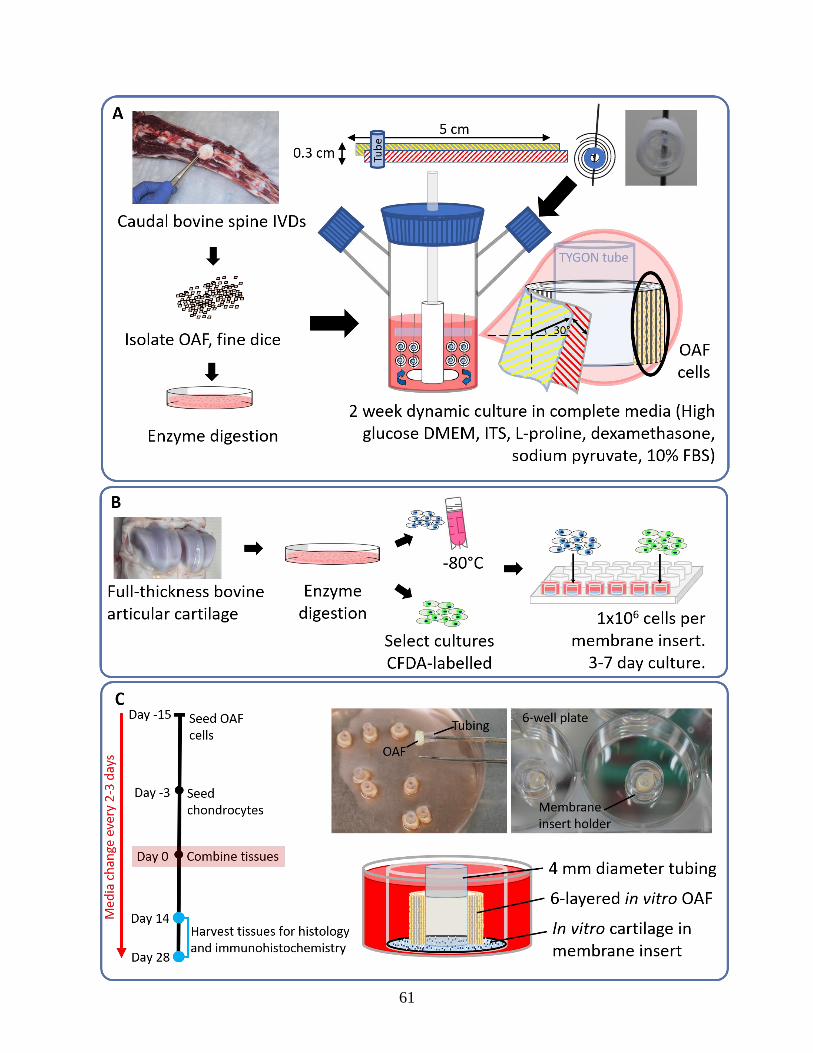
61
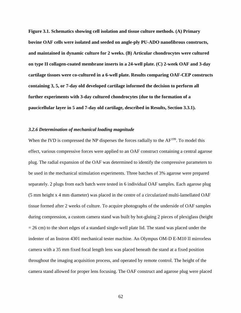
62
Figure 3.1. Schematics showing cell isolation and tissue culture methods. (A) Primary
bovine OAF cells were isolated and seeded on angle-ply PU-ADO nanofibrous constructs,
and maintained in dynamic culture for 2 weeks. (B) Articular chondrocytes were cultured
on type II collagen-coated membrane inserts in a 24-well plate. (C) 2-week OAF and 3-day
cartilage tissues were co-cultured in a 6-well plate. Results comparing OAF-CEP constructs
containing 3, 5, or 7-day old developed cartilage informed the decision to perform all
further experiments with 3-day cultured chondrocytes (due to the formation of a
paucicellular layer in 5 and 7-day old cartilage, described in Results, Section 3.3.1).
3.2.6 Determination of mechanical loading magnitude
When the IVD is compressed the NP disperses the forces radially to the AF199. To model this
effect, various compressive forces were applied to an OAF construct containing a central agarose
plug. The radial expansion of the OAF was determined to identify the compressive parameters to
be used in the mechanical stimulation experiments. Three batches of 3% agarose were prepared
separately. 2 plugs from each batch were tested in 6 individual OAF samples. Each agarose plug
(5 mm height x 4 mm diameter) was placed in the centre of a circularized multi-lamellated OAF
tissue formed after 2 weeks of culture. To acquire photographs of the underside of OAF samples
during compression, a custom camera stand was built by hot-gluing 2 pieces of plexiglass (height
= 26 cm) to the short edges of a standard single-well plate lid. The stand was placed under the
indenter of an Instron 4301 mechanical tester machine. An Olympus OM-D E-M10 II mirrorless
camera with a 35 mm fixed focal length lens was placed beneath the stand at a fixed position
throughout the imaging acquisition process, and operated by remote control. The height of the
camera stand allowed for proper lens focusing. The OAF construct and agarose plug were placed
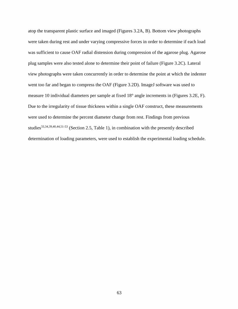
63
atop the transparent plastic surface and imaged (Figures 3.2A, B). Bottom view photographs
were taken during rest and under varying compressive forces in order to determine if each load
was sufficient to cause OAF radial distension during compression of the agarose plug. Agarose
plug samples were also tested alone to determine their point of failure (Figure 3.2C). Lateral
view photographs were taken concurrently in order to determine the point at which the indenter
went too far and began to compress the OAF (Figure 3.2D). ImageJ software was used to
measure 10 individual diameters per sample at fixed 18° angle increments in (Figures 3.2E, F).
Due to the irregularity of tissue thickness within a single OAF construct, these measurements
were used to determine the percent diameter change from rest. Findings from previous
studies33,34,39,40,44,51-53 (Section 2.5, Table 1), in combination with the presently described
determination of loading parameters, were used to establish the experimental loading schedule.
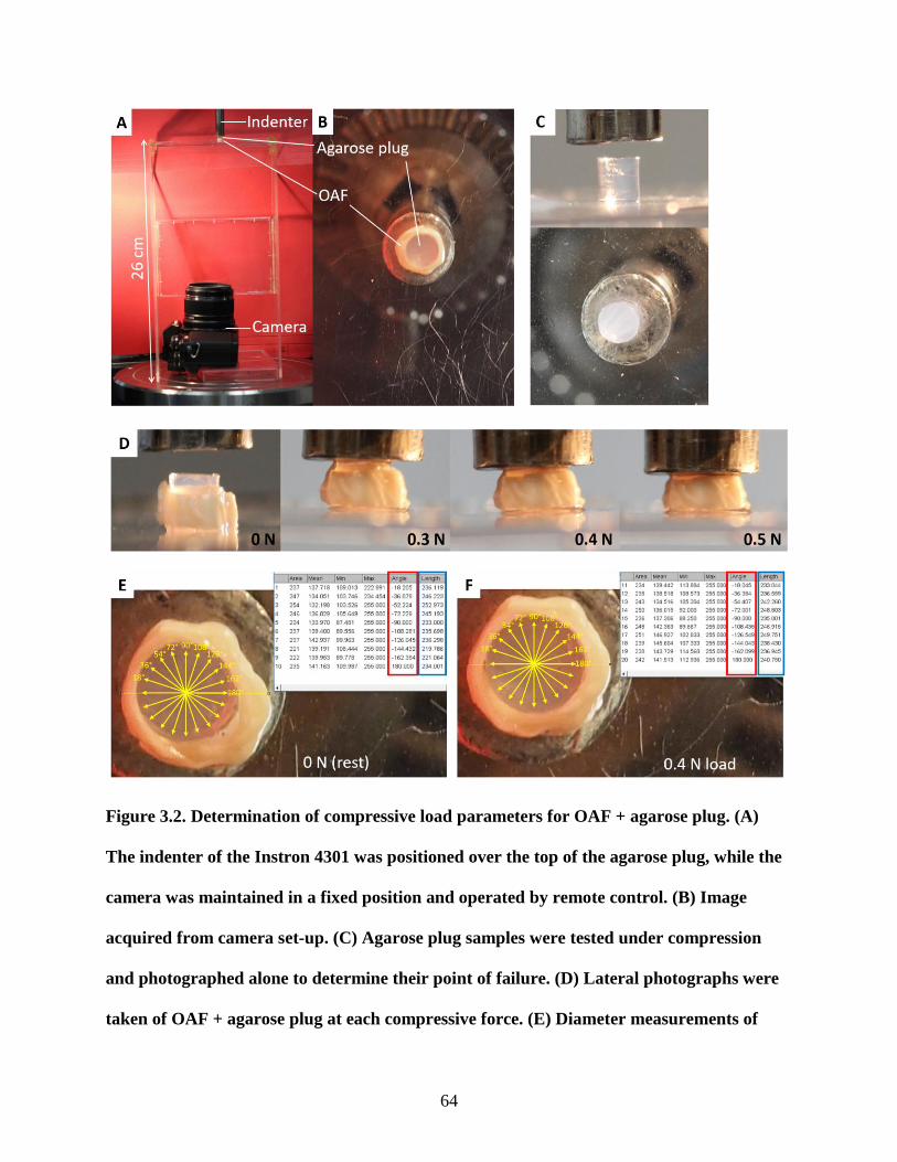
64
Figure 3.2. Determination of compressive load parameters for OAF + agarose plug. (A)
The indenter of the Instron 4301 was positioned over the top of the agarose plug, while the
camera was maintained in a fixed position and operated by remote control. (B) Image
acquired from camera set-up. (C) Agarose plug samples were tested under compression
and photographed alone to determine their point of failure. (D) Lateral photographs were
taken of OAF + agarose plug at each compressive force. (E) Diameter measurements of
65
OAF + plug at rest and (F) under compression using ImageJ. Diameters were measured at
fixed 18° angle increments (yellow arrows, red boxed data) to obtain a total of 10 length
measurements for each sample (blue boxed data).
3.2.7 Dynamic mechanical loading of OAF-CEP constructs
During the third week of a 4-week co-culture period, OAF-CEP constructs were subjected to
dynamic compressive stimulation 3 times (Monday, Wednesday, Friday) using parameters
determined in 3.2.6. The TYGON tubing was removed from 2-week co-cultured OAF-CEP
constructs under sterile conditions. A 3% agarose plug (5 mm height x 4 mm diameter) was
carefully inserted into the centre of each OAF-CEP construct using thin tweezers. Four
constructs contained in their plastic insert holders and conditioned media were placed in the
outside corner wells of a 24-well plate, which was covered with a custom-designed jig consisting
of titanium alloy loading platens and a Teflon plate cover (Supplemental Figure S4). The jig
indenters (diameter = 8.8 mm) were lowered onto the agarose plug and compressive forces were
applied by a Mach-1™ mechanical tester (Biomomentum) (Figure 3.3A).
An axial compression force of 0.4 N per sample was applied at 1 Hz for 1800 cycles (Figure
3.3B). Immediately after mechanical stimulation, samples were returned to their culture plates
and replenished with complete media. Control constructs did not receive mechanical stimulation
but otherwise were treated in the same manner. All constructs were maintained in culture for
another week without stimulation.
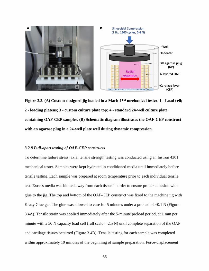
66
Figure 3.3. (A) Custom-designed jig loaded in a Mach-1™ mechanical tester. 1 - Load cell;
2 - loading platens; 3 - custom culture plate top; 4 - standard 24-well culture plate
containing OAF-CEP samples. (B) Schematic diagram illustrates the OAF-CEP construct
with an agarose plug in a 24-well plate well during dynamic compression.
3.2.8 Pull-apart testing of OAF-CEP constructs
To determine failure stress, axial tensile strength testing was conducted using an Instron 4301
mechanical tester. Samples were kept hydrated in conditioned media until immediately before
tensile testing. Each sample was prepared at room temperature prior to each individual tensile
test. Excess media was blotted away from each tissue in order to ensure proper adhesion with
glue to the jig. The top and bottom of the OAF-CEP construct was fixed to the machine jig with
Krazy Glue gel. The glue was allowed to cure for 5 minutes under a preload of ~0.1 N (Figure
3.4A). Tensile strain was applied immediately after the 5-minute preload period, at 1 mm per
minute with a 50 N capacity load cell (full scale = 2.5 N) until complete separation of the OAF
and cartilage tissues occurred (Figure 3.4B). Tensile testing for each sample was completed
within approximately 10 minutes of the beginning of sample preparation. Force-displacement
67
graphs were generated and the maximum force value in Newtons was calculated. To obtain
normalized kPa stress values, the contact surface area of each detached OAF was measured.
OAF tissue contact surface area was painted with black ink to allow for visualization. Care was
taken to ensure that only the apparent contact area was marked. Inked samples were
photographed with an Olympus OM-D E-M10 II camera, and the surface area was measured by
manually tracing the inked area using ImageJ software (Figures 3.4C, D). Each sample was
traced 3 separate times to obtain an average surface area value. Samples that did not fully
separate during tensile testing were saved for histology in order to examine the pattern of early
failure at the interface. These samples were not included in the calculation of tensile strength.
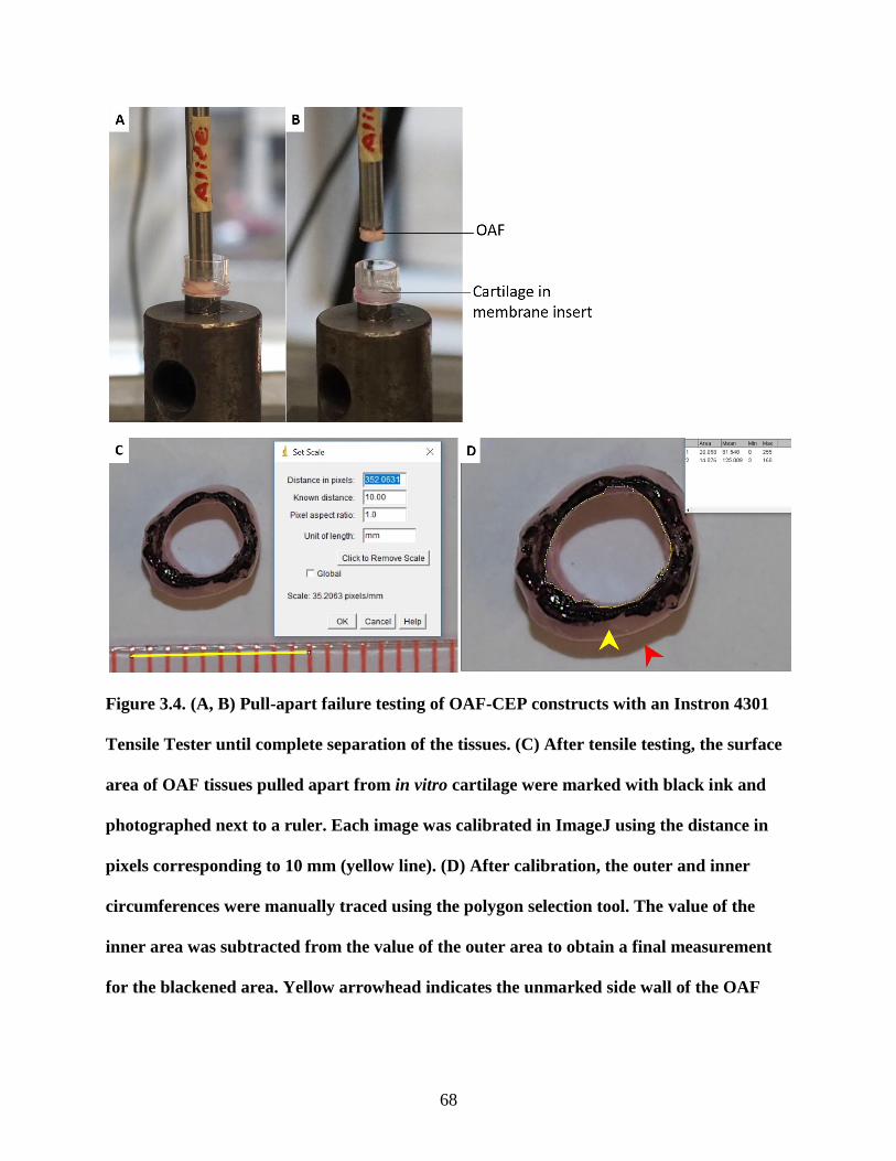
68
Figure 3.4. (A, B) Pull-apart failure testing of OAF-CEP constructs with an Instron 4301
Tensile Tester until complete separation of the tissues. (C) After tensile testing, the surface
area of OAF tissues pulled apart from in vitro cartilage were marked with black ink and
photographed next to a ruler. Each image was calibrated in ImageJ using the distance in
pixels corresponding to 10 mm (yellow line). (D) After calibration, the outer and inner
circumferences were manually traced using the polygon selection tool. The value of the
inner area was subtracted from the value of the outer area to obtain a final measurement
for the blackened area. Yellow arrowhead indicates the unmarked side wall of the OAF
69
tissue that was not in contact with cartilage. Red arrowhead indicates shadow produced by
camera flash.
3.2.9 Histological characterization of native and in vitro OAF-CEP interface
Harvested in vitro tissues were fixed in 10% buffered formalin for 1 hour and immersed in 30%
sucrose overnight. Native bovine caudal IVDs with attached CEP and VB were fixed in 10%
buffered formalin for 48 hours, decalcified in 0.5 M EDTA for 4 weeks, and immersed in 30%
sucrose for 48 hours. In vitro and native samples were embedded in optimal cutting temperature
compound embedding medium and kept frozen at -30°C until cryostat sectioning. 7 µm-thick
frozen sections were mounted on cryotape200 (Cryofilm type 2C, SECTION-LAB Co. Ltd.) and
subsequently adhered onto glass slides using UV-activated optical glue (Norland Optical
Adhesive 61, Norland Products Inc.) as previously described201. Glued sections were allowed to
cure under a biosafety cabinet UV lamp for 1 hour (Supplemental Figure S5). Adhered sections
were stained with hematoxylin and eosin (H&E) or toluidine blue, and imaged under light
microscopy.
3.2.10 Immunohistochemical characterization of the OAF-CEP interface model
For collagen type I and type II immunostaining, cryotape-adhered sections were subjected to
antigen retrieval by sequential enzyme digestion as follows: Pepsin (2.5 mg/mL in TBS pH 2.0;
P7012, Sigma) for 10 minutes at room temperature followed by two washes in PBS-/- for 10
minutes; Trypsin (2.5 mg/mL in TBS; T7409, Sigma) for 30 minutes at room temperature
followed by one wash in PBS-/- for 5 minutes; Hyaluronidase (25 mg/mL in PBS-/-; H3506,
Sigma) for 30 minutes at 37°C followed by one wash in PBS-/- for 5 minutes. For aggrecan

70
immunostaining, sections underwent antigen retrieval with hyaluronidase only for 30 minutes at
37°C followed by one wash in PBS-/- for 5 minutes. Sections were blocked with 20% goat serum
and 0.1% Triton X-100 in PBS-/- for 1 hour at room temperature, washed for 5 minutes in PBS-
/-, and incubated overnight at 4°C with primary antibodies reactive with collagen type I (1:75
dilution; ab34710, Abcam), collagen type II (1:75 dilution; MAB8887, Millipore), and aggrecan
(1:750 dilution; AHP002, Invitrogen). Rabbit and mouse IgG were used as negative controls.
Antibody diluent consisted of 10% goat serum and 0.1% Triton X-100 in PBS-/-. After overnight
incubation, sections were washed in PBS-/- (once for 5 minutes, twice for 15 minutes) and
incubated for 1 hour at room temperature with fluorescent labelled secondary antibodies
suspended in antibody diluent. Goat anti-mouse IgG (1:1000 dilution; A11032, Invitrogen) or
goat anti-rabbit IgG (1:1000 dilution; A11008, Invitrogen) secondary antibodies were used
depending on the source of the primary antibodies. Sections were washed three times in PBS -/-
(once for 5 minutes, twice for 15 minutes) and incubated with DAPI (1:10 000 in PBS-/-) for 5
minutes to stain nuclei. Slides were washed three times in PBS-/- for 5 minutes, and coverslipped
with PermaFluor mounting medium (TA-030-FM, Thermo Scientific). Slides were protected
from light and allowed to dry for 48 hours before visualization under a Zeiss Axioplan
fluorescent microscope.
3.2.11 Quantification of DNA, collagen, and proteoglycan contents
In vitro OAF-CEP tissues were removed from the insert holder using a scalpel. To isolate the
tissue interface region, 1 mm of the OAF tissue in contact with the cartilage layer was cut with a
scalpel under a dissecting microscope (Figure 3.5A). 3-mm and 7-mm biopsy punches were used
to cut the cartilage inside and around the OAF tissue, respectively (Figure 3.5B). In vitro
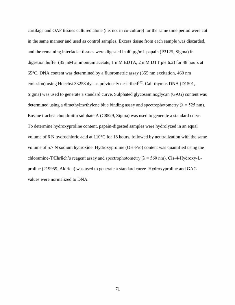
71
cartilage and OAF tissues cultured alone (i.e. not in co-culture) for the same time period were cut
in the same manner and used as control samples. Excess tissue from each sample was discarded,
and the remaining interfacial tissues were digested in 40 µg/mL papain (P3125, Sigma) in
digestion buffer (35 mM ammonium acetate, 1 mM EDTA, 2 mM DTT pH 6.2) for 48 hours at
65°C. DNA content was determined by a fluorometric assay (355 nm excitation, 460 nm
emission) using Hoechst 33258 dye as previously described202. Calf thymus DNA (D1501,
Sigma) was used to generate a standard curve. Sulphated glycosaminoglycan (GAG) content was
determined using a dimethylmethylene blue binding assay and spectrophotometry (λ = 525 nm).
Bovine trachea chondroitin sulphate A (C8529, Sigma) was used to generate a standard curve.
To determine hydroxyproline content, papain-digested samples were hydrolyzed in an equal
volume of 6 N hydrochloric acid at 110°C for 18 hours, followed by neutralization with the same
volume of 5.7 N sodium hydroxide. Hydroxyproline (OH-Pro) content was quantified using the
chloramine-T/Ehrlich’s reagent assay and spectrophotometry (λ = 560 nm). Cis-4-Hydroxy-L-
proline (219959, Aldrich) was used to generate a standard curve. Hydroxyproline and GAG
values were normalized to DNA.
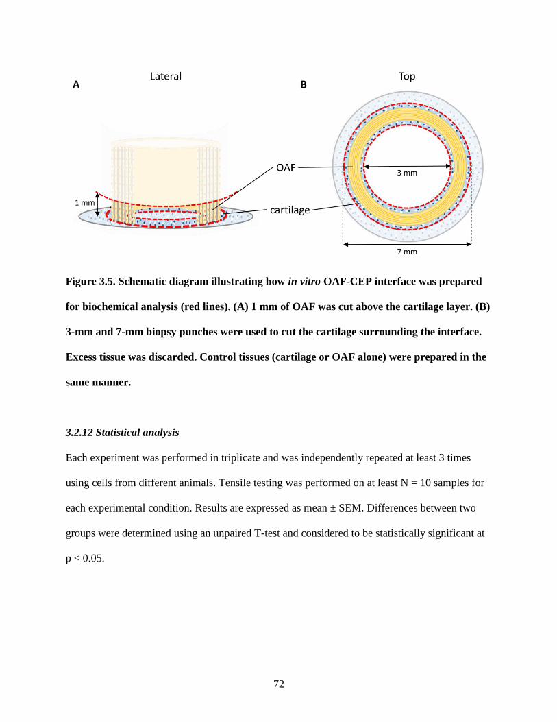
72
Figure 3.5. Schematic diagram illustrating how in vitro OAF-CEP interface was prepared
for biochemical analysis (red lines). (A) 1 mm of OAF was cut above the cartilage layer. (B)
3-mm and 7-mm biopsy punches were used to cut the cartilage surrounding the interface.
Excess tissue was discarded. Control tissues (cartilage or OAF alone) were prepared in the
same manner.
3.2.12 Statistical analysis
Each experiment was performed in triplicate and was independently repeated at least 3 times
using cells from different animals. Tensile testing was performed on at least N = 10 samples for
each experimental condition. Results are expressed as mean ± SEM. Differences between two
groups were determined using an unpaired T-test and considered to be statistically significant at
p < 0.05.
73
3.3 Results
3.3.1 Co-culture of in vitro OAF on cartilage tissue generated an integrated tissue interface
Six-layer angle-ply OAF tissues remained in place (i.e. did not dislodge from the cartilage layer)
upon the addition of media on day 2 of co-culture, indicating that some degree of attachment
between the two tissues had occurred by this time. The two tissues were integrated as early as 1
week of co-culture (Figure 3.6B). Histology confirmed the presence of OAF tissue composed of
elongated cells aligned parallel to the PU-ADO scaffold (Figures 3.6C, D), which was confirmed
by SEM to contained aligned nanofibers (Supplemental Figure S6). Interestingly, the OAF cells
were aligned parallel to the cartilage layer at the interface (Figure 3.6E), which was similar to the
alignment seen in the native fetal OAF-CEP interface (Figure 3.6G). Scaffold layer ends of the
model were oriented downwards perpendicular to the cartilage layer (Figure 3.6E, F), similar to
what occurs in the native interface. OAF tissue alone did not stain for proteoglycan (Figure
3.6D), however cartilage tissue rich in toluidine blue-positive ECM was present (Figure 3.6F).
2-week developed OAF tissue integrated with cartilage tissues that were pre-grown for 3, 5, and
7 days. At the interface, a paucicellular layer of ECM developed in the superficial aspect of the
cartilage of 5-day old CEP-like tissue (Figure 3.7B). This layer appeared thicker and more
distinct in constructs formed with 7-day pre-grown cartilage (Figure 3.7C). 7-day in vitro tissues
forming cartilage alone (i.e. not co-cultured) did not have this layer prior to placement in co-
culture. Similar to 3-day old cartilage alone (Figures 3.7D, E), 7-day old cartilage alone
contained evenly distributed cells throughout the tissue (Figures 3.7F, G). 3-day, 5-day and 7-
day old cartilage grown for an additional 2 weeks in AF-optimized DMEM complete media
appeared to have accumulated a thicker top layer of paucicellular ECM than did the cartilage
74
grown in control Ham’s F12 media (Figures 3.7H-M). The paucicellular layer that was seen at
the interface between OAF and older in vitro cartilage tissues was therefore not a pre-existing
characteristic of the pre-grown cartilage, and appeared to develop from prolonged culture with
AF-optimized DMEM media. These findings informed the decision to perform all further
experiments with chondrocytes grown for 3 days, in order to avoid the appearance of an
interfacial ECM layer with sparse cellularity.
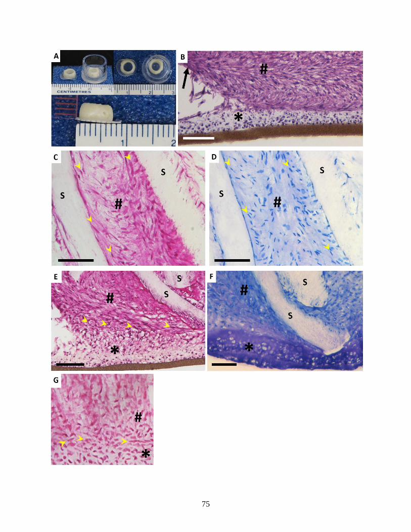
75
76
Figure 3.6. (A) Lateral and top macroscopic views of 2-week co-cultured OAF-CEP tissue
constructs. Constructs are shown as they appeared both before and after removal from
plastic membrane insert holders. (B) 2-week old OAF and 3-day old cartilage integrated by
1 week of co-culture. Arrow indicates the outermost edge of the in vitro OAF. (C) OAF
tissue formed between layers of PU-ADO scaffold in the in vitro OAF region, and (D) did
not stain for proteoglycan. (E, F) In vitro-formed interface of OAF-CEP co-cultured for 2
weeks. (G) Native fetal bovine OAF-CEP interface. Yellow arrowheads indicate directional
orientation of OAF cells along PU-ADO scaffold layers (C, D), parallel to the cartilage
layer at the in vitro interface (E), and parallel to the CEP of native fetal interface (G). # =
OAF; * = cartilage; S = PU-ADO scaffold. H&E (B, C, E, G) and toluidine blue (D, F)
stained. Light microscopy. Scale bars represent 100 µm.
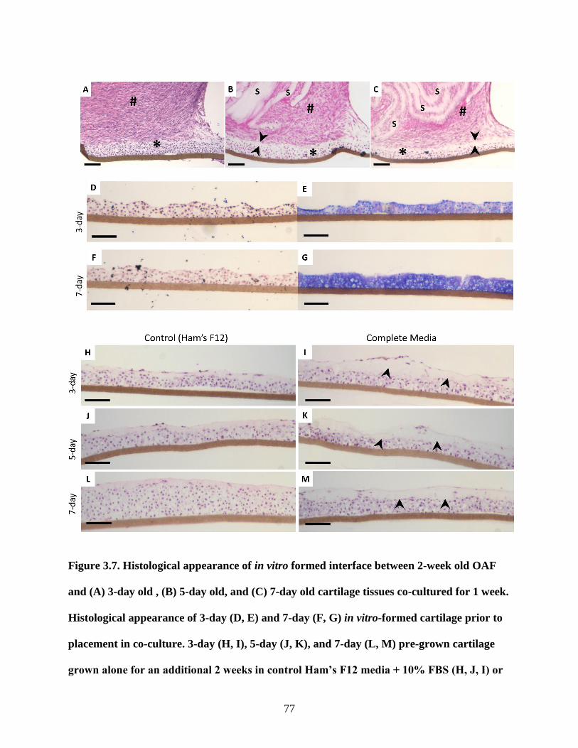
77
Figure 3.7. Histological appearance of in vitro formed interface between 2-week old OAF
and (A) 3-day old , (B) 5-day old, and (C) 7-day old cartilage tissues co-cultured for 1 week.
Histological appearance of 3-day (D, E) and 7-day (F, G) in vitro-formed cartilage prior to
placement in co-culture. 3-day (H, I), 5-day (J, K), and 7-day (L, M) pre-grown cartilage
grown alone for an additional 2 weeks in control Ham’s F12 media + 10% FBS (H, J, I) or
78
complete DMEM AF-optimized media (I, K, M). S = PU-ADO scaffold; # = OAF; * =
cartilage; arrowheads = paucicellular layer of ECM. H&E (A-C, D, F, H-M) and toluidine
blue stained (E, G). Light microscopy. Scale bars represent 100 µm. NB: OAF-CEP
constructs (A-C) were assembled without physical support of tubing, which led to
convolution of scaffold layers and a lack of perpendicular insertion into the cartilage layer.
3.3.2 Chondrocytes remained localized to the cartilage layer beneath the interface
To determine if the integration was related to cells migrating in both directions (i.e. chondrocytes
migrating into the AF tissues or vice-versa), the chondrocytes were labelled with green
fluorescent CFDA dye. At two weeks, when there was sufficient integration to handle the
constructs, examination of histological sections under fluorescent microscopy showed that the
fluorescent labelled cells were localized to the cartilage layer and did not appear to migrate up
into the OAF (Figure 3.8). The morphological features of spindled cells resembling OAF cells
suggested that these cells were growing down into the cartilage layer to form the interface.
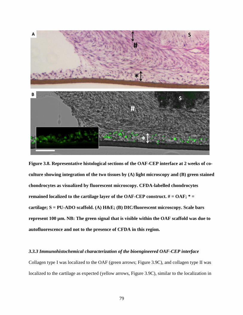
79
Figure 3.8. Representative histological sections of the OAF-CEP interface at 2 weeks of co-
culture showing integration of the two tissues by (A) light microscopy and (B) green stained
chondrocytes as visualized by fluorescent microscopy. CFDA-labelled chondrocytes
remained localized to the cartilage layer of the OAF-CEP construct. # = OAF; * =
cartilage; S = PU-ADO scaffold. (A) H&E; (B) DIC/fluorescent microscopy. Scale bars
represent 100 µm. NB: The green signal that is visible within the OAF scaffold was due to
autofluorescence and not to the presence of CFDA in this region.
3.3.3 Immunohistochemical characterization of the bioengineered OAF-CEP interface
Collagen type I was localized to the OAF (green arrows; Figure 3.9C), and collagen type II was
localized to the cartilage as expected (yellow arrows, Figure 3.9C), similar to the localization in
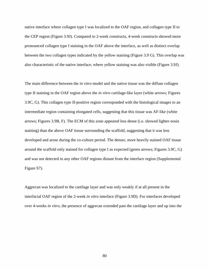
80
native interface where collagen type I was localized to the OAF region, and collagen type II to
the CEP region (Figure 3.9J). Compared to 2-week constructs, 4-week constructs showed more
pronounced collagen type I staining in the OAF above the interface, as well as distinct overlap
between the two collagen types indicated by the yellow staining (Figure 3.9 G). This overlap was
also characteristic of the native interface, where yellow staining was also visible (Figure 3.9J).
The main difference between the in vitro model and the native tissue was the diffuse collagen
type II staining in the OAF region above the in vitro cartilage-like layer (white arrows; Figures
3.9C, G). This collagen type II-positive region corresponded with the histological images to an
intermediate region containing elongated cells, suggesting that this tissue was AF-like (white
arrows; Figures 3.9B, F). The ECM of this zone appeared less dense (i.e. showed lighter eosin
staining) than the above OAF tissue surrounding the scaffold, suggesting that it was less
developed and arose during the co-culture period. The denser, more heavily stained OAF tissue
around the scaffold only stained for collagen type I as expected (green arrows; Figures 3.9C, G)
and was not detected in any other OAF regions distant from the interface region (Supplemental
Figure S7).
Aggrecan was localized to the cartilage layer and was only weakly if at all present in the
interfacial OAF region of the 2-week in vitro interface (Figure 3.9D). For interfaces developed
over 4-weeks in vitro, the presence of aggrecan extended past the cartilage layer and up into the
81
OAF tissue (Figure 3.9H). The presence of aggrecan in the OAF region at 4 weeks resembled the
presence of aggrecan in the native interface (Figure 3.9K).
Figure 3.9. Representative histological appearance of the in vitro interface following
staining by H&E (A, B, E, F) and corresponding immunostaining for collagen type I
(green) and type II (red) (C, G) and aggrecan (D, H) of 2-week (A-D), and 4-week (E-H)
constructs. Representative histological staining by H&E (I) and corresponding
immunostaining for collagen types I and II (J), and aggrecan (K) of the native young
bovine OAF-CEP interface. Nuclei were stained with DAPI (blue). Green arrows = in vitro
OAF tissue; White arrows = intermediate in vitro OAF-like tissue; Yellow arrows = in vitro
cartilage tissue; White arrowheads = presence of aggrecan in in vitro OAF region. # = in
82
vitro OAF; * = in vitro cartilage; S = PU-ADO scaffold. Light microscopy (A, B, E, F, I) and
fluorescent microscopy (C, D, G, H, J, K). Scale bars represent 100 µm.
3.3.4 Apparent mechanical strength of the in vitro OAF-CEP interface increased over time
Pull-apart failure testing revealed that 2-week cultured OAF-CEP constructs a possessed
measurable interfacial mechanical strength of 11.9 ± 1.8 kPa, which was significantly increased
to 21.0 ± 2.2 kPa at 4-weeks of co-culture (p = 0.002) (Figure 3.10A). Histological examination
revealed that the failure occurred between the OAF and cartilage layer in all constructs (Figures
3.10B, C). In addition to this predominating failure pattern, mid-substance failure was also
observed whereby the failure occurred either within the cartilage (Figure 3.10D) or the within the
OAF (Figure 3.10E) rather than between the two tissues at the interface. These mid-substance
modes of failure were rare and were only each observed once among the 6 samples examined.
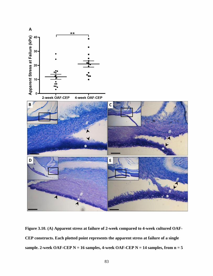
83
Figure 3.10. (A) Apparent stress at failure of 2-week compared to 4-week cultured OAF-
CEP constructs. Each plotted point represents the apparent stress at failure of a single
sample. 2-week OAF-CEP N = 16 samples, 4-week OAF-CEP N = 14 samples, from n = 5
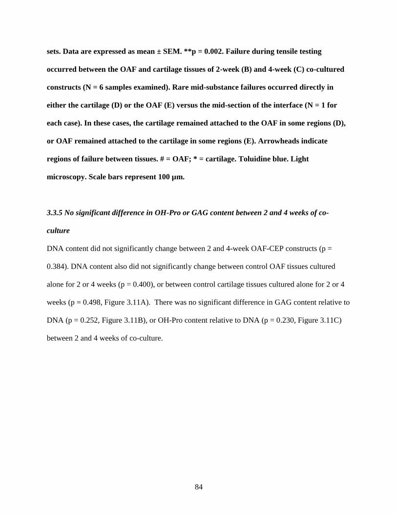
84
sets. Data are expressed as mean ± SEM. **p = 0.002. Failure during tensile testing
occurred between the OAF and cartilage tissues of 2-week (B) and 4-week (C) co-cultured
constructs (N = 6 samples examined). Rare mid-substance failures occurred directly in
either the cartilage (D) or the OAF (E) versus the mid-section of the interface (N = 1 for
each case). In these cases, the cartilage remained attached to the OAF in some regions (D),
or OAF remained attached to the cartilage in some regions (E). Arrowheads indicate
regions of failure between tissues. # = OAF; * = cartilage. Toluidine blue. Light
microscopy. Scale bars represent 100 µm.
3.3.5 No significant difference in OH-Pro or GAG content between 2 and 4 weeks of co-
culture
DNA content did not significantly change between 2 and 4-week OAF-CEP constructs (p =
0.384). DNA content also did not significantly change between control OAF tissues cultured
alone for 2 or 4 weeks (p = 0.400), or between control cartilage tissues cultured alone for 2 or 4
weeks (p = 0.498, Figure 3.11A). There was no significant difference in GAG content relative to
DNA (p = 0.252, Figure 3.11B), or OH-Pro content relative to DNA (p = 0.230, Figure 3.11C)
between 2 and 4 weeks of co-culture.
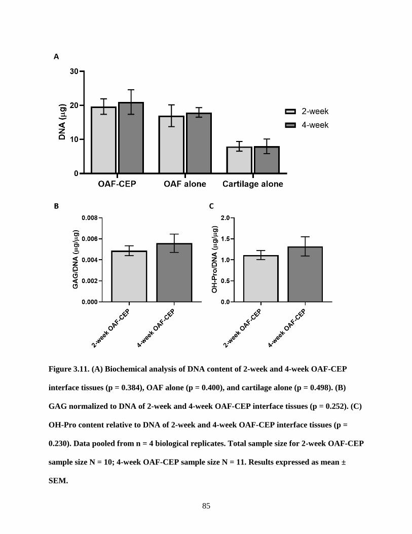
85
Figure 3.11. (A) Biochemical analysis of DNA content of 2-week and 4-week OAF-CEP
interface tissues (p = 0.384), OAF alone (p = 0.400), and cartilage alone (p = 0.498). (B)
GAG normalized to DNA of 2-week and 4-week OAF-CEP interface tissues (p = 0.252). (C)
OH-Pro content relative to DNA of 2-week and 4-week OAF-CEP interface tissues (p =
0.230). Data pooled from n = 4 biological replicates. Total sample size for 2-week OAF-CEP
sample size N = 10; 4-week OAF-CEP sample size N = 11. Results expressed as mean ±
SEM.
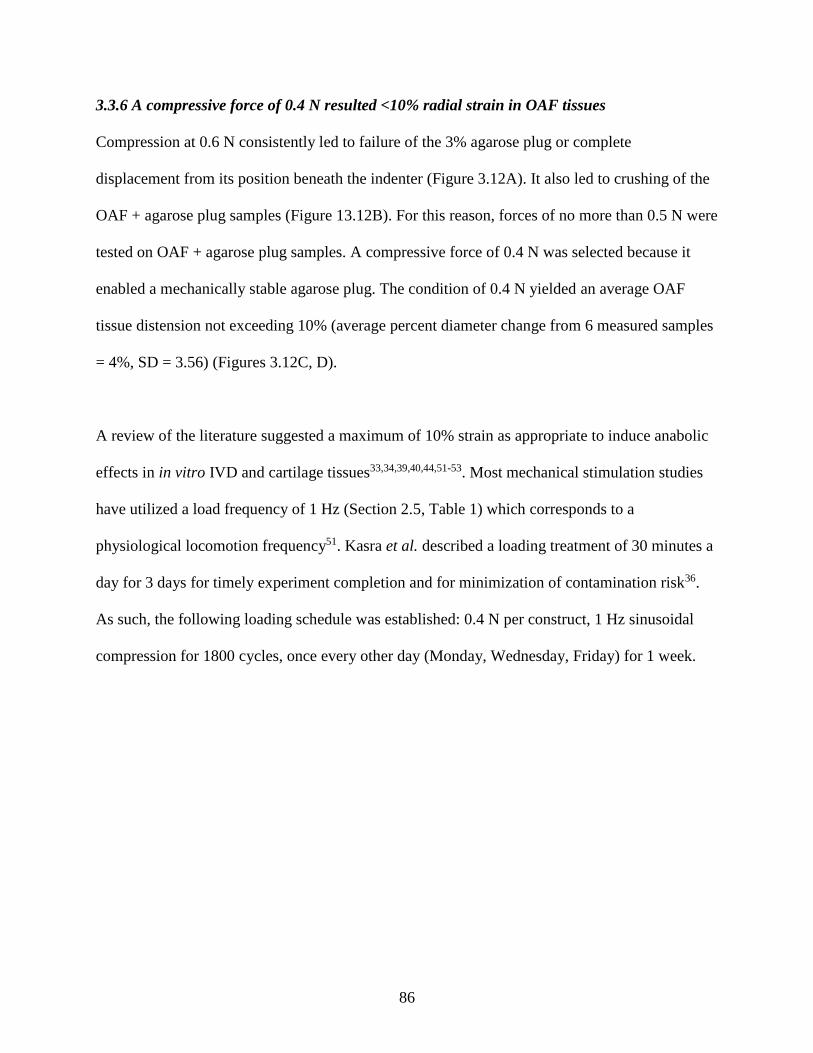
86
3.3.6 A compressive force of 0.4 N resulted <10% radial strain in OAF tissues
Compression at 0.6 N consistently led to failure of the 3% agarose plug or complete
displacement from its position beneath the indenter (Figure 3.12A). It also led to crushing of the
OAF + agarose plug samples (Figure 13.12B). For this reason, forces of no more than 0.5 N were
tested on OAF + agarose plug samples. A compressive force of 0.4 N was selected because it
enabled a mechanically stable agarose plug. The condition of 0.4 N yielded an average OAF
tissue distension not exceeding 10% (average percent diameter change from 6 measured samples
= 4%, SD = 3.56) (Figures 3.12C, D).
A review of the literature suggested a maximum of 10% strain as appropriate to induce anabolic
effects in in vitro IVD and cartilage tissues33,34,39,40,44,51-53. Most mechanical stimulation studies
have utilized a load frequency of 1 Hz (Section 2.5, Table 1) which corresponds to a
physiological locomotion frequency51. Kasra et al. described a loading treatment of 30 minutes a
day for 3 days for timely experiment completion and for minimization of contamination risk36.
As such, the following loading schedule was established: 0.4 N per construct, 1 Hz sinusoidal
compression for 1800 cycles, once every other day (Monday, Wednesday, Friday) for 1 week.
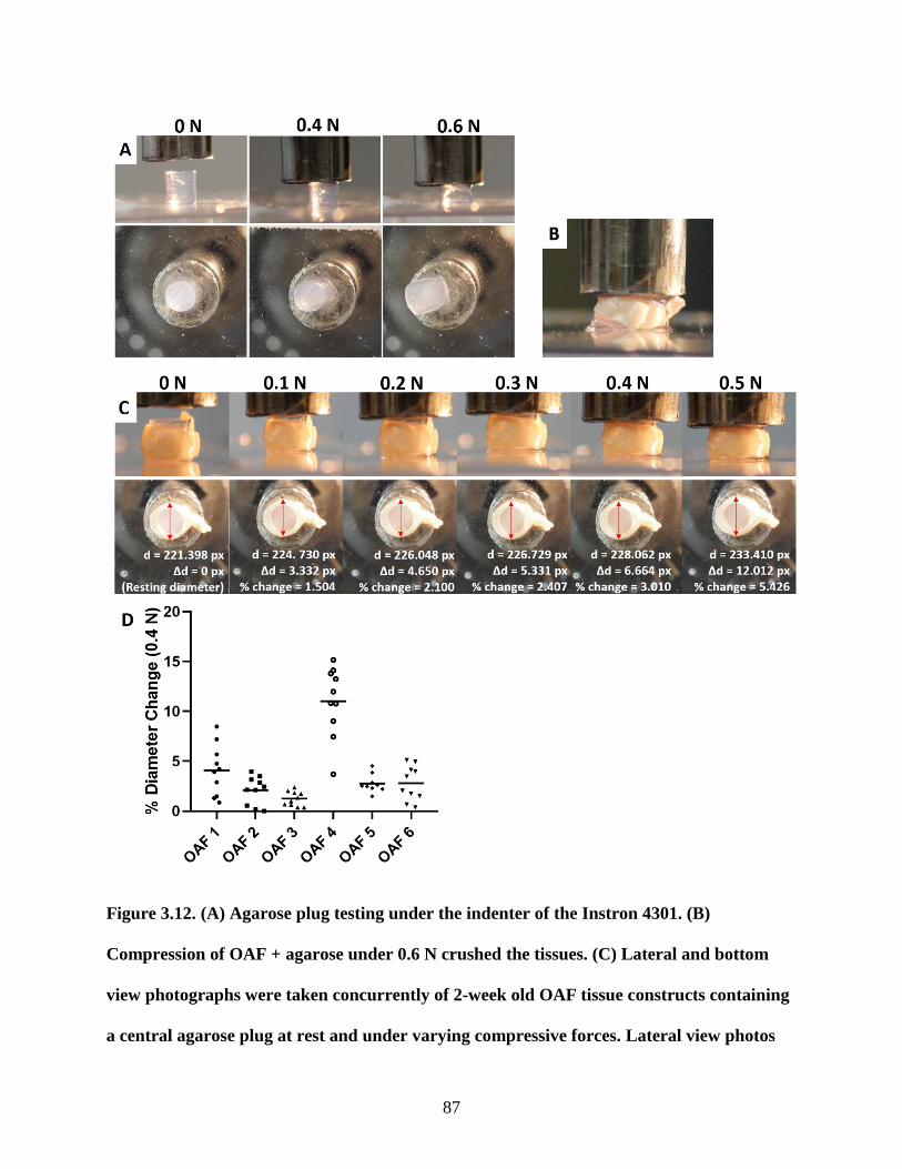
87
Figure 3.12. (A) Agarose plug testing under the indenter of the Instron 4301. (B)
Compression of OAF + agarose under 0.6 N crushed the tissues. (C) Lateral and bottom
view photographs were taken concurrently of 2-week old OAF tissue constructs containing
a central agarose plug at rest and under varying compressive forces. Lateral view photos
88
(upper panel) are not to scale. Red arrows = OAF diameter bottom view measurement for
each compressive force in ImageJ (example of only one 90° angle measurement for N = 1
sample is shown). d = Measured bottom diameter in unit image pixels (px). ∆d = Unit
change in diameter compared to the resting diameter. % change = Percentage of diameter
increase in comparison to the resting diameter. (D) Mean distribution of diameter
measurements taken from N = 6 OAF samples under 0.4 N load. Each plotted point
represents one of ten diameter measurements for each sample.
3.3.7 Dynamic mechanical stimulation did not significantly increase the apparent tensile
strength, collagen content, or proteoglycan content in OAF-CEP interface constructs
4-week co-cultured OAF-CEP constructs that received dynamic loading every other day during
the third week of a 4-week culture period did not significantly differ in apparent tensile strength
compared to 4-week cultured OAF-CEP constructs that received no loading (p = 0.111) (Figure
3.13A).
There were no obvious differences in the presence of proteoglycan as indicated by toluidine blue
staining between 2 and 4-week constructs (Figures 3.13B, E). Immunostaining of 4-week old
loaded and unloaded OAF-CEP constructs did not show a change in collagen type I, collagen
type II (Figures 3.13C, F) or aggrecan distribution (Figures 3.13D, G) at the interface. 30
minutes of 1 Hz, 0.4 N dynamic compressive loading every other day for 1 week led to the
destruction of the interface in n = 2 out of the 3 constructs examined (Figures 3.13H-J).
89
There was no significant difference in the quantification of DNA content (p = 0.329), GAG
relative to DNA (p = 0.347), or OH-Pro relative to DNA (p = 0.179) when comparing unloaded
and loaded 4-week OAF-CEP constructs (Figures 3.13K-M).
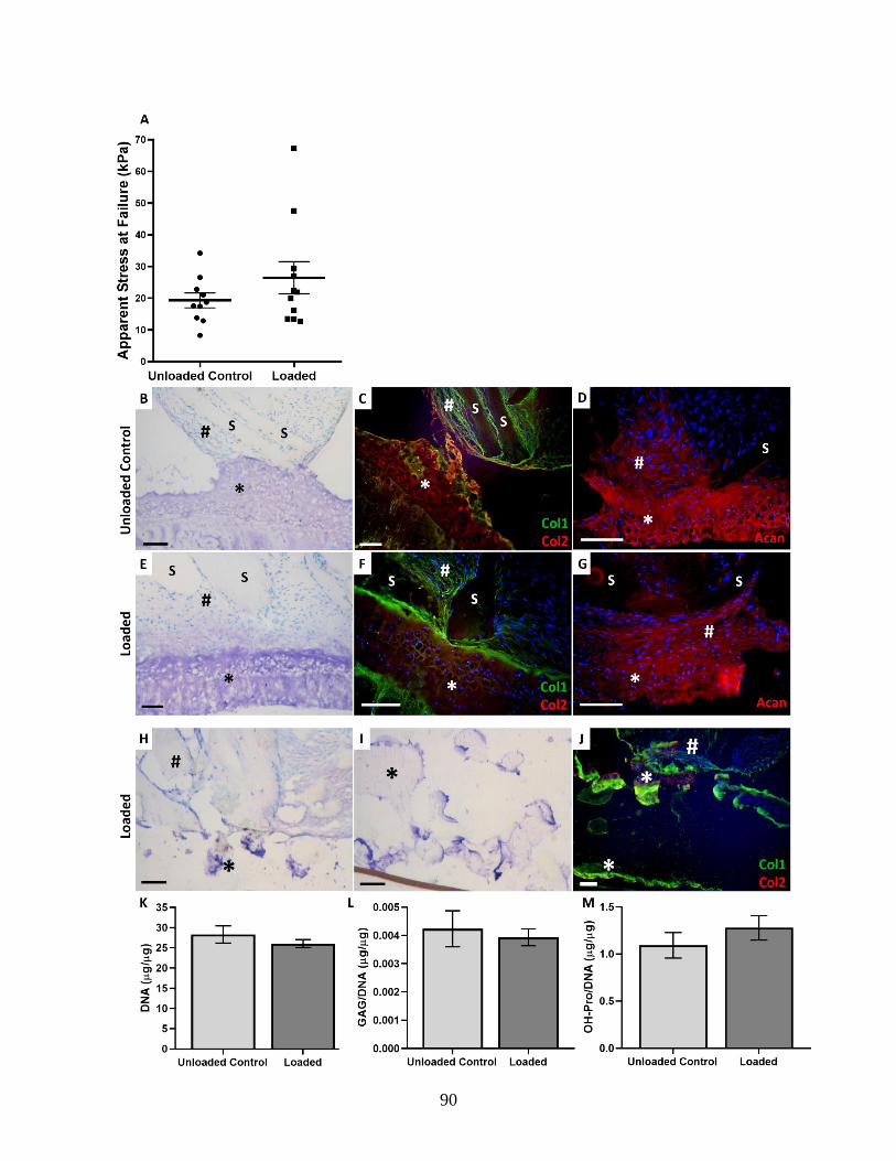
90
91
Figure 3.13. (A) Apparent stress at failure between unloaded control and loaded OAF-CEP
constructs. Each plotted point represents the apparent stress at failure of a single sample.
Data pooled from n = 4 biological replicates. 4-week unloaded control total sample size N =
10; 4-week Dynamic Loaded total sample size N=11. Data expressed as mean ± SEM. 4-
week unloaded control (B-D) and loaded OAF-CEP constructs (E-G). Histology (B, E)
corresponds to the immunostaining for collagen type I (green), collagen type II (red) (C, F),
and aggrecan (red) (D, G). Dynamic loading led to destruction of the interface in n = 2 out
of 3 samples examined as shown by histological staining (H, I) and immunostaining (J). # =
OAF; * = cartilage; S = PU-ADO scaffold. Toluidine blue stained, light microscopy (B, E,
H, I). Fluorescent microscopy (C, D, F, G, J). Scale bars represent 100 µm. NB: The
separation at the interface (C) was due to tissue processing during the immunostaining. (K)
DNA content, (L) GAG/DNA content, and (M) OH-Pro/DNA content between unloaded
control and loaded OAF-CEP interface tissues. Data pooled from n = 4 biological
replicates. 4-week unloaded control total sample size N = 11; 4-week Dynamic Loaded total
sample size N=10. Data expressed as mean ± SEM.
92
CHAPTER 4: DISCUSSION
4.1 Summary
The objective of the current thesis was to develop a structurally integrated, biomimetic OAF-
CEP interface model, and to determine if the mechanical strength at the interface could be
enhanced by cyclic compressive loading. In order to accomplish this, in vitro OAF-like tissues
were generated using AF cells seeded into multilamellar angle-ply nanofibrous PU-ADO
scaffolds, which were placed in static co-culture on top of in vitro formed cartilage tissues. This
resulted in integrated tissue constructs containing an interface which had mechanical strength
that increased significantly between 2 and 4 weeks.
The morphology of the cells and ECM at the interface had features that modeled the native OAF-
CEP. More specifically, the elongated OAF cells were aligned parallel to the cartilage layer at
the interface, similar to what was observed in the native fetal tissue. The localization patterns of
collagen types I and II resembled that of native OAF-CEP, and both collagen types were
intermixed at the interfacial region. Unlike native tissue, diffuse collagen type II was present in
the in vitro interfacial OAF and had a histological appearance of loose AF-like tissue; the denser
OAF tissue distant to this zone only stained for collagen type I. Aggrecan was present at the
interface and extended into the OAF region above the interface by 4 weeks of co-culture, similar
to its diffuse distribution in native interfacial OAF. OAF cells appeared to grow into the cartilage
layer at the interface, while chondrocytes demonstrated minimal, if any, migration up into the
OAF region by remaining localized to the cartilage over the 4 weeks of the culture study. Failure
of the interface during tensile testing predominately occurred between the OAF and CEP-like
tissues, with rare occurrences of mid-substance failure in either of the original two tissue states.
93
Although it was possible to generate an in vitro model of the OAF-Cartilage interface, the cyclic
compressive loading studies performed to date did not demonstrate an effect on the strength,
organization or composition of the interface in the time period studied.
4.2 Discussion and Study Limitations
4.2.1 Use of in vitro-formed OAF tissue on aligned angle-ply PU-ADO nanofibrous
scaffolds and hyaline-like cartilage are suitable to generate an OAF-CEP model
During development in vivo, the organization of elongated fibroblast-like AF cells into aligned,
lattice-like concentric sheets precedes the appearance of collagen70,71. The polarized orientation
of AF cells presumably promotes the aligned deposition of collagen fibres to form the fully
developed AF tissue91. The current in vitro-generated OAF model mimicked this process,
whereby seeded AF cells first attached and oriented with aligned, angle-ply, fibronectin-coated
nanofibers, which then allowed for subsequent directed accumulation of aligned ECM174,175.
Alignment of electrospun polymer nanofibers has been shown to promote aligned AF cell
orientation, whereas randomly oriented fibres led to irregular cell orientation and less collagen
type I and proteoglycan production29. The present study confirmed that collagen type I
accumulation between scaffold layers mimicked the interlamellar distribution of collagen type I
in native OAF tissue (Supplemental Figure S7). This suggests that the in vitro-formed OAF
tissue was appropriate for use in this model.
In vitro CEP-like tissues were not formed by chondrocytes of the very thin native bovine CEP,
but rather from the more abundant supply of articular chondrocytes from metacarpal-phalangeal
joints. This was necessary in order to obtain a sufficient number of cells to perform all the
94
experiments. The IVD CEP and the articulating surfaces of synovial joints are similarly
comprised of hyaline cartilage. The current study demonstrated that the in vitro cartilage formed
by articular chondrocytes was rich in collagen type II, similar to the native CEP63. The in vitro-
formed cartilage contained aggrecan, which has also previously been shown to be present in the
native CEP (Rok 2017, unpublished), and in the current study (Figure 3.9). Furthermore, native
CEP tissue was shown to increase matrix proteoglycan accumulation of in vitro-formed NP
tissue when placed in co-culture, and this anabolic effect was mimicked by in vitro cartilage
formed in 3D culture by articular chondrocytes105. From this, it was suggested that chondrocytes
of both CEP and articulating joints produce similar factors that may promote IVD cell growth
and/or ECM synthesis105. These data suggest that in vitro cartilage formed by articular
chondrocytes was an appropriate tissue to model the CEP in the current study. Incorporation of a
similar in vitro-formed cartilage layer in a triphasic NP-CEP-VB model was previously shown to
have improved shear strength when compared to a biphasic NP-VB construct, adding support to
the rationale for the need to include a cartilaginous component in an IVD-VB interface model203.
A Teflon porous membrane was chosen as the substrate on which to form the in vitro cartilage in
the current model based on previous studies that have used the same method of 3D cartilage
generation196,204. However, other studies have generated in vitro cartilage from articular
chondrocytes in 3D culture on top of calcium polyphosphate (CPP), a hard bone-like
substrate105,198,205. Waldman et al. reported that the ECM of cartilage tissues grown on CPP
contained similar amounts of collagen but more proteoglycans over eight weeks compared to
tissues grown on the more flexible Teflon membrane inserts, suggesting that ECM composition
is dependent on the underlying substrate on which it is grown204,205. The specific effect of

95
culturing chondrocytes on a Teflon membrane compared to CPP is unknown from this study,
however substrate stiffness may have various effects on cell behaviour and may play a role. For
example, Schuh et al. found that articular chondrocytes seeded on soft polymer gels had a
rounder shape and showed higher collagen type II and aggrecan gene expression in comparison
to chondrocytes seeded on stiffer gels206. The effect of substrate material properties should be
investigated with respect to the current model in terms of ECM production, composition, and the
ability to integrate with multilamellated OAF tissues, as the focus will eventually shift to
integration with a hard bone substitute (i.e. CPP) as part of a complete implant model.
4.2.2 Requirements for successful co-culture of in vitro OAF and cartilage tissues
To determine the optimal age of pre-grown cartilage for integration with in vitro OAF tissues,
articular chondrocytes were cultured for 3, 5, or 7 days before being placed in co-culture. The
AF-cartilage interface formed more reliably if 3-day old cartilage was used in the OAF-CEP
construction. When placed in co-culture, OAF cells and interfacial chondrocytes of 3-day pre-
grown cartilage organized in a manner similar to what is seen in native fetal interface tissue.
Tissue constructs assembled from 5-day pre-grown cartilage developed a layer of paucicellular
ECM between the OAF and the deeper zone of the cartilage. This layer was even more
pronounced in 7-day old cartilage. Hence, the age of the developed cartilage used in this system
was important, as different outcomes were observed depending on the pre-culture period. The
zone of ECM with sparse cellularity is believed to have developed as a result of the culture
conditions, as cartilage grown alone in complete AF-optimized DMEM media accumulated a
similarly paucicellular ECM layer in the superficial region of the tissue over time (Figure 3.7).
Paucicellular ECM did not accumulate to such an extent in cartilage formed in Ham’s F12 media
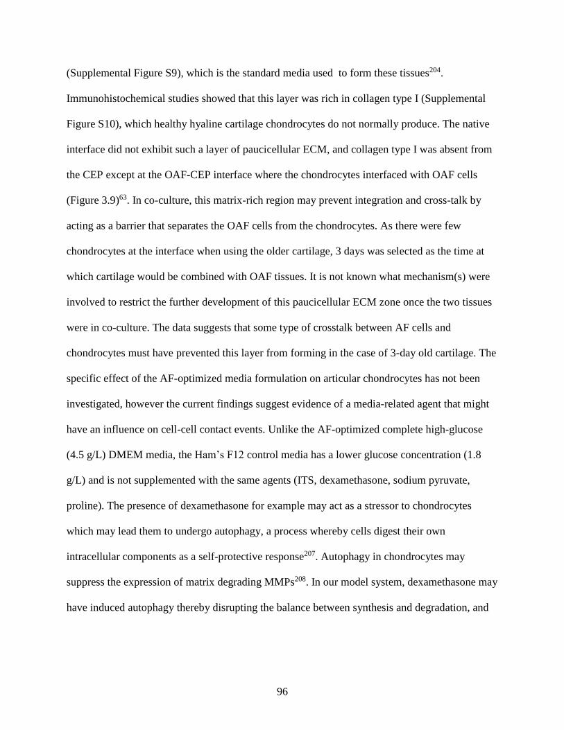
96
(Supplemental Figure S9), which is the standard media used to form these tissues204.
Immunohistochemical studies showed that this layer was rich in collagen type I (Supplemental
Figure S10), which healthy hyaline cartilage chondrocytes do not normally produce. The native
interface did not exhibit such a layer of paucicellular ECM, and collagen type I was absent from
the CEP except at the OAF-CEP interface where the chondrocytes interfaced with OAF cells
(Figure 3.9)63. In co-culture, this matrix-rich region may prevent integration and cross-talk by
acting as a barrier that separates the OAF cells from the chondrocytes. As there were few
chondrocytes at the interface when using the older cartilage, 3 days was selected as the time at
which cartilage would be combined with OAF tissues. It is not known what mechanism(s) were
involved to restrict the further development of this paucicellular ECM zone once the two tissues
were in co-culture. The data suggests that some type of crosstalk between AF cells and
chondrocytes must have prevented this layer from forming in the case of 3-day old cartilage. The
specific effect of the AF-optimized media formulation on articular chondrocytes has not been
investigated, however the current findings suggest evidence of a media-related agent that might
have an influence on cell-cell contact events. Unlike the AF-optimized complete high-glucose
(4.5 g/L) DMEM media, the Ham’s F12 control media has a lower glucose concentration (1.8
g/L) and is not supplemented with the same agents (ITS, dexamethasone, sodium pyruvate,
proline). The presence of dexamethasone for example may act as a stressor to chondrocytes
which may lead them to undergo autophagy, a process whereby cells digest their own
intracellular components as a self-protective response207. Autophagy in chondrocytes may
suppress the expression of matrix degrading MMPs208. In our model system, dexamethasone may
have induced autophagy thereby disrupting the balance between synthesis and degradation, and
97
may have thus contributed to the accumulation of the thick ECM layer. Further study is required
to investigate the mechanism(s) involved in the formation of this paucicellular ECM zone.
An important aspect of the current model design was the perpendicular orientation of the
nanofibrous scaffold fibres towards the cartilage layer. This modeled the portion of OAF
collagen fibers that inserts vertically into the CEP at the native interface63,100. An earlier
construct assembly method prevented this perpendicular scaffold orientation. Macroscopically,
in vitro OAF tissue appeared to be contractile when placed in static culture without the internal
support of the TYGON tubing (Method 1 of co-culture, Appendix Section 6.2; Supplemental
Figure S1A). Microscopically, this led to curled and convoluted scaffold layers within the OAF
ECM (Supplemental Figure S1D). The presence of tubing within the OAF tissues during static
co-culture prevented PU-ADO scaffold convolution and collapse that was seen with Method 1 of
co-culture, as determined histologically (Supplemental Figure S1B, E). Cell-mediated
contraction has been suggested to depend on the stiffness of the scaffold209, which is in
agreement with the current finding that the provision of a stiffer physical support by the tubing
prevented visible contraction of OAF cell-seeded PU-ADO scaffolds. As OAF cells aligned with
the scaffold layers, it may be assumed that deformed scaffold lamellae led to abnormal
orientation of the OAF cells and therefore to irregular collagen fibre orientation at the interface
in this model system. This was not desired as the purpose of the model design was to recreate the
organized structure of the highly linear native OAF fibres. Maintenance of the tubing during co-
culture allowed for the ends of scaffold layers to be oriented perpendicular to the cartilage layer,
similar to the way in which collagen fibres insert into the native CEP63,100.
98
In order for the TYGON tubing to be maintained within the OAF tissue during co-culture, it was
also necessary for the cartilage layer to be maintained in its insert holder. In one experiment, 3-
day old in vitro cartilage and its underlying membrane were excised from tension (the holder).
OAF tissues with a central TYGON tube were then placed on top of the excised membrane and
cartilage within a 6-well plate and co-cultured in complete media. After 24 hours, only one of
three OAF constructs formed an attachment with the underlying cartilage (data not shown). The
two OAF tissues that failed to attach to the cartilage contracted and had completely pushed out
their tubing. The tension provided by the insert holder kept the cartilage tissue flat, which
facilitated attachment with OAF tissues.
4.2.3 Characterization of the OAF-CEP interface
The in vitro formed OAF and cartilage tissues resembled their native counterparts with respect to
cell morphology, cell orientation, and ECM characteristics. OAF cells at the interface aligned
parallel to the cartilage layer, which mimicked the orientation of OAF cells adjacent to the native
fetal CEP. Chondrocytes remained localized to the proteoglycan-rich in vitro cartilage layer,
which appeared histologically distinct from the OAF tissue. Similar to the native OAF-CEP
which was characterized both previously63 and in the current study (Figures 3.9I-K),
immunostaining showed that the in vitro cartilage-like tissue was abundant in collagen type II,
and that the OAF-like tissue contained collagen type I. The intermixing of both collagen types I
and II at the interface mimicked what was observed at the native interface. The co-localization of
collagen types I and II has been linked to biomechanical properties and load transfer at the
tendon-bone insertion site. Collagen type I is localized in the aligned fibres of the tendinous
region (similar to the OAF) while collagen types II and I are localized to the fibrocartilage
99
adjacent to the bony region of the insertion site210,211. Differences in viscoelastic properties found
in the bony insertion region as compared to the tendinous region suggested that the latter was
more highly resistant to tension211. Therefore, the differences in ECM collagen localization and
organization may be a result of load transfer, whereby tensile stress is transferred
unidirectionally along the aligned collagen type I fibres and distributed to the collagen type II/I-
containing ECM which is less organized therefore able to transfer multidirectional forces to the
underlying bone211. Although the tendon insertion is structurally very different than the OAF-
CEP interface, the overlap of collagen types I and II observed at the transition zone of the in
vitro and in vivo OAF-CEP interface suggests that this model has a composition that would
enable it to appropriately distribute forces in a manner similar to what occurs physiologically.
Collagen type II, normally not present in OAF tissues, was present in the OAF region at the
interface at both 2 and 4 weeks. Histological examination showed that this collage type II-
positive zone contained elongated cells within a loose ECM, suggesting that this tissue was
developing AF-like tissue. A possible reason for this may be that AF cells proliferated and
deposited new ECM at this interfacial region, which may explain why the tissue in this zone
appeared looser than the pre-grown OAF tissue surrounding the scaffold. The influence of the
adjacent cartilage may have induced these AF cells to produce collagen type II by a crosstalk
mechanism. Alternatively, collagen type II synthesized by the chondrocytes may have diffused
into this looser AF-like tissue. In situ hybridization for collagen type II mRNA expression would
be required to determine if AF cell(s) are responsible for the production of collagen type II, in
order to support either of these hypotheses.
100
Aggrecan, a proteoglycan that is responsible for the compressive-resistant nature of hyaline
cartilage212, was detected in the in vitro-formed OAF at the interface by 4 weeks of co-culture,
which resembled its appearance in native interfacial OAF tissue. Aggrecan was absent in the
OAF distant from the interface region as expected, as its presence in the native IVD is lowest in
the OAF in comparison to the NP and IAF30. The distribution of aggrecan in the native disc
follows the type of stresses each region experiences; the NP predominantly experiences
compressive stress and therefore contains the highest amount of compressive-resistant aggrecan,
while the OAF experiences radial tensile stress and therefore contains high amounts of tensile-
resistant collagen type I64,213.
Although proteoglycan (aggrecan) remained mostly localized to the cartilage layer at 2 weeks
and appeared in the interfacial OAF tissue by 4 weeks, it should be noted that when biochemical
analysis of the interface region was performed, no difference was shown in the proteoglycan and
collagen contents relative to DNA over time. DNA content also remained unchanged. One
possible explanation for this discrepancy is that the proteoglycan may have diffused from the
cartilage layer into the OAF over time, thereby altering its distribution but not its overall content.
An alternative explanation is that crosstalk with the cartilage layer may have induced
proteoglycan synthesis by OAF cells at a level too low to detect as a difference by the GAG
assay, however this is purely speculative. The specific effect(s) of chondrocyte co-culture on
OAF cell phenotype and matrix production remains an area of study that, to our knowledge, has
not been investigated to date.
101
It must be noted that the methods used to prepare tissues for biochemical analysis had several
limitations. Firstly, despite using a standard method of tissue dissection for all samples, it was
difficult to isolate only the interfacial region of each construct. Biopsy punches were used in
order to standardize the amount of cartilage cut away from the constructs. Cutting away excess
cartilage directly from OAF tissue edges (i.e. using a scalpel) would have resulted in different
amounts of tissue being removed from each construct due to the inherently irregular shape of
each individual OAF tissue. 3-mm and 7-mm biopsy punches were therefore chosen to trim
excess cartilage, however both left behind overhanging tissue around the OAF. A 4-mm biopsy
punch was too large to fit into the centre of the OAF, and a 6-mm biopsy punch was too small to
fit around the entire perimeter of the irregularly shaped OAF tissues. Dissection of the OAF 1
mm above the interface was performed by hand under a dissecting microscope. Precision using
this method was difficult to achieve. As a result, the tissues analysed for biochemistry contained
both interfacial and non-interfacial tissues, which likely affected the biochemical values
obtained. Secondly, the biochemical assays used for determination of overall DNA, OH-Pro and
sulfated GAG content may not have been sensitive enough to determine significant small
changes at the interface. The excess cartilage tissue around the interface and the 1 mm of OAF
tissue above the interface may have concealed any detectable OH-Pro or GAG changes that had
occurred in the interface region over time. Lastly, as the assays were only able to detect overall
hydroxyproline and GAG content, they did not provide any information as to whether different
subtypes of collagen or proteoglycan may have increased or decreased over time.
Another aim was to determine the cellular composition at the interface, more specifically
whether chondrocytes were migrating upwards into the OAF region. Notochordal cells have been
102
shown to promote CEP chondrocyte migration in vitro214, however the effect of AF cells on
chondrocyte migration is unknown. CFDA has low toxicity to cells at appropriate concentrations
and has been used previously to show migration of chondrocytes from engineered cartilage into
adjacent host cartilage198. Upon diffusion into the cell, CFDA is cleaved by intracellular
esterases and reacts with intracellular amines to produce a stable fluorescent signal. The results
showed that the green-labelled cells in 2-week constructs remained within the cartilage layer and
did not migrate up into the OAF. Examination of a CFDA-labelled cells of the 4-week construct
did not show evidence of chondrocyte migration into the OAF, however the fluorescent signal
was much weaker compared to the 2-week construct. A limitation of using CFDA is that its
concentration is reduced by half with each cell division. Thus, it is not known whether the
decrease in staining reflected AF cell migration into the cartilage, or chondrocyte proliferation
causing dilution of the dye below detectable limits. Stable, long-term labelling of both
chondrocytes and OAF cells by transfection with green or red fluorescent protein would confirm
the exact distribution of OAF cells and chondrocytes at the interface.
4.2.4 Failure testing and apparent mechanical strength of the OAF-CEP interface
Axial tensile testing to failure revealed that co-culture time had a significant effect on the
mechanical strength of OAF-CEP interface constructs. 2-week co-cultured constructs possessed
measurable mechanical strength, which was significantly enhanced by 4 weeks of co-culture.
Collagen type I and collagen type II appeared to accumulate at the interface from 2 to 4 weeks of
co-culture as shown by immunostaining. This suggested that while attachment between OAF and
CEP-like tissues occurred early (within 1 week of co-culture, visible by histology), there was a
103
period of development and ECM deposition that functioned to further enhance the integration
and mechanical strength between the two tissues.
It was of importance to note that although there was no difference in the quantified ECM
proteoglycan or collagen contents between 2 and 4 weeks of co-culture, there was an increase in
the apparent mechanical strength of the interface. There are several possible explanations for
this. It is possible that small changes in matrix accumulation at particular points along the
interface may have been insufficient to be detected by the relatively insensitive biochemical
assays. Despite using a standard method of tissue dissection for all samples, it was difficult to
isolate only the interfacial region of each construct for subsequent biochemical analysis. Due to
this lack of precision, excess non-interfacial OAF and cartilage tissues were included in the
biochemical analyses which may have masked any small ECM changes that occurred specifically
at the narrow interface region. Inherent variability within interface tissues, manifesting for
example in the form of discontinuities within integrated constructs (Supplemental Figure S8) and
non-uniform protein distribution along the length of the interface due to the presence of a
scaffold layer (seen in Figure 3.13F), also limited the accuracy of biochemical quantification,
thereby limiting our ability to isolate the specific points of integration that may have been
responsible for the enhanced mechanical strength.
While the increase in mechanical strength therefore cannot be directly explained by any
significant increases in overall collagen or proteoglycan content per mg of DNA, the apparent
accumulation of collagen types I and II at the interface, as well as the increase in aggrecan across
the interface boundary as detected by immunostaining, may provide an indirect explanation for
104
the increased mechanical strength that was observed in 4-week as compared to 2-week tissues.
The proteoglycan seen in the interfacial OAF tissue at 4 weeks may be an indication of tissue
remodelling, which may have contributed to the increase in apparent interfacial strength.
Hedlund et al. provided evidence that aggrecan monomers interact directly with collagen fibrils
through their keratin sulfate-rich domains215. Increasing such aggrecan-collagen interactions in
the interfacial OAF over time may have enhanced the mechanical properties at this region. Due
to its osmotic swelling properties, the main role of aggrecan in cartilaginous tissues is to resist
compressive forces while collagen fibres resist tensile forces64,216. The increased spreading of
aggrecan through the OAF therefore does not necessarily explain the higher tensile strength
observed at the interface. However, it does indicate that some level of ECM remodelling might
have occurred in the tissue and that this may have contributed to the observed increase in tensile
strength.
Similar to the presently observed increase in tensile strength as a result of tissue maturation,
previous work by Williamson et al. found that increases in both compressive and tensile
properties from fetal to mature cartilage were not related to changes in quantified proteoglycan
content, but to an increase in the amount of pyridinoline, a chemical cross-link of collagen217,218.
The proportion of mature compared to immature collagen cross-links has also been shown to
increase with cartilage tissue maturity219. Lysyl oxidase is the enzyme that is responsible for the
formation of pyridinoline cross-links in both collagen and elastin220, and has been suggested to
improve integrity and integration strength between TE and native cartilage221. Thus, the observed
increase in apparent mechanical strength may reflect increased activity of this enzyme resulting
in the catalyzation of collagen cross-links. Alternatively, just as fibrils of the native AF extend
105
towards adjacent CEPs to form interconnections with them in the later stages of development
(seventh embryonic month in humans)74, it may be that increased collagen fibril intermingling
occurred with maturity of the model interface. Cartilage collagen fibril diameter and alignment
have also been shown to increase with maturity, which was related to an increase in mechanical
properties219. The OH-Pro assay used in the present study only quantified the amount of
collagen, and not the level of fibril cross-linking, intermingling, size, or organization. Scanning
electron microscopy imaging may provide insight into the level of collagen fibril intermingling,
organization, and diameter increase at the interface over time. Quantification of lysyl oxidase
gene and protein expression, as well as pyridinoline cross-link content at the in vitro OAF-CEP
interface should be performed to determine if a cross-linking mechanism is responsible for the
enhanced mechanical strength observed at the interface over time, in the absence of changes in
collagen content.
The weaker interface at 2 weeks raises the possibility that tissue remodelling may have been
more dynamic at this early time point, with the possibly of more protease activity leading to less
stable ECM. Matrix metalloproteinases (MMPs) are enzymes that mediate ECM remodelling by
regulating ECM protein degradation, cell migration, and molecular signalling222. Their specific
roles with respect to IVD development have not been extensively investigated. However, one
study found that MMP-1, MMP-3, MMP-14, and active MMP-2 were more highly present in the
NP, AF and CEP of human fetal IVDs than in non-fetal IVDs, suggesting that MMP-mediated
degradative processes may contribute to IVD ECM remodelling during early tissue development
and may be less active as maturity is approached223. In this regard, the development of ECM and
106
mechanical strength over time in the current model may have been mimicking the temporal
progression of physiological developmental remodelling processes.
In vivo, the mineralized layer of the CEP serves to reinforce the anchorage of native AF fibrils
into the CEP and the underlying bone100. In the current model, OAF scaffold fibres did not
extend through the entire length of CEP and there was no calcified cartilage present to provide
the ability for integration with a mineralized layer. This is likely one reason why construct failure
predominantly occurred at the attachment site between the OAF and cartilage rather than within
each respective tissue. The native interface is mechanically stable under tension. Uniaxial tensile
failure testing of native bovine VB-OAF-VB samples found that failure never occurred at the
OAF-CEP interface; it rather occurred in the adjacent VB growth plate or OAF tissue, with
failure stress values between 1.2 and 1.4 MPa depending on the number of lamellae present in
each sample (Rok 2017, unpublished). In comparison, the apparent mechanical strength of the
current engineered model was 21 kPa, approximately 57 times weaker than the mechanical
strength of native VB-OAF-VB segments containing 6-10 lamellae (Rok 2017, unpublished).
Importantly, it was noted that failure within our in vitro interface occurred between the OAF and
cartilage tissues, and rarely occurred within the OAF or cartilage phases themselves. Since the
current developed model focused only on the AF-hyaline cartilage interface and did not have
features to mimic native AF-VB fibril insertion or CEP mineralization, it is not unexpected that
the tensile failure strength of the generated interface was not yet comparable to that of the native
interface. The native OAF-CEP interface normally possesses a high degree of mechanical
strength due to the extension of the AF collagen fibers through the CEP and mineralized
cartilage, and into the VB1,102. Sapiee et al. demonstrated that failure across the AF-CEP-VB
107
interface occurred either in the soft AF tissue or in the vertebral bone itself, where AF fibres
pulled out the VB osteons with them, indicating a high degree of integration with the VB102.
Thus, mimicking the anchorage of the AF through a cartilage layer, a mineralized cartilage layer,
and then into a subchondral bone region should be a goal of further experiments in order to
strengthen the tissue-engineered AF-cartilage interface. Despite its limitations, this model system
will still allow for studies on the first critical steps of integration that will facilitate the
recapitulation of mechanical stability following implantation.
The apparent mechanical strength of the interface model was estimated using maximum force
measurements obtained at failure during axial tensile testing, which was dependant on
determining the apparent surface area of the OAF in contact with the cartilage. The major
limitation here was that OAF-cartilage contact area was assumed to be the surface area
measured. However, this may not necessarily be an accurate assumption as it is unknown if all of
the OAF tissues were in contact and fully integrated with the underlying cartilage tissue. OAF
contact surfaces were painted with black ink in order to provide enough contrast for tissue edge
detection during imaging and surface area determination. Tracing the surface area in ImageJ was
performed manually due to irregularities in the OAF tissue images (i.e. holes and discontinuities
within the tissues, ambient light reflections). It is acknowledged that this method of surface area
determination was crude, as ink was applied by hand, and the tracing of surface area using
ImageJ software was performed manually. The methods were however kept consistent
throughout, and the obtained mechanical strength results are reported as apparent values.
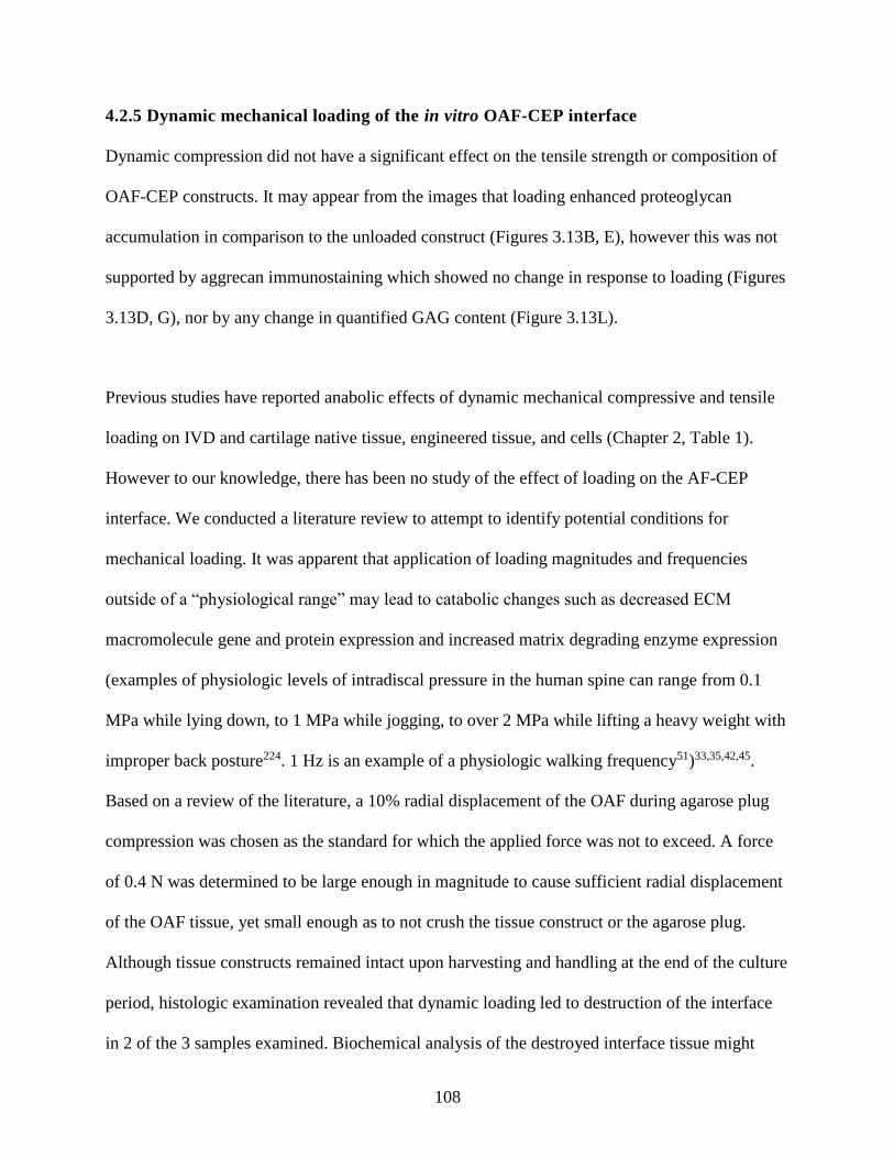
108
4.2.5 Dynamic mechanical loading of the in vitro OAF-CEP interface
Dynamic compression did not have a significant effect on the tensile strength or composition of
OAF-CEP constructs. It may appear from the images that loading enhanced proteoglycan
accumulation in comparison to the unloaded construct (Figures 3.13B, E), however this was not
supported by aggrecan immunostaining which showed no change in response to loading (Figures
3.13D, G), nor by any change in quantified GAG content (Figure 3.13L).
Previous studies have reported anabolic effects of dynamic mechanical compressive and tensile
loading on IVD and cartilage native tissue, engineered tissue, and cells (Chapter 2, Table 1).
However to our knowledge, there has been no study of the effect of loading on the AF-CEP
interface. We conducted a literature review to attempt to identify potential conditions for
mechanical loading. It was apparent that application of loading magnitudes and frequencies
outside of a “physiological range” may lead to catabolic changes such as decreased ECM
macromolecule gene and protein expression and increased matrix degrading enzyme expression
(examples of physiologic levels of intradiscal pressure in the human spine can range from 0.1
MPa while lying down, to 1 MPa while jogging, to over 2 MPa while lifting a heavy weight with
improper back posture224. 1 Hz is an example of a physiologic walking frequency51)33,35,42,45.
Based on a review of the literature, a 10% radial displacement of the OAF during agarose plug
compression was chosen as the standard for which the applied force was not to exceed. A force
of 0.4 N was determined to be large enough in magnitude to cause sufficient radial displacement
of the OAF tissue, yet small enough as to not crush the tissue construct or the agarose plug.
Although tissue constructs remained intact upon harvesting and handling at the end of the culture
period, histologic examination revealed that dynamic loading led to destruction of the interface
in 2 of the 3 samples examined. Biochemical analysis of the destroyed interface tissue might
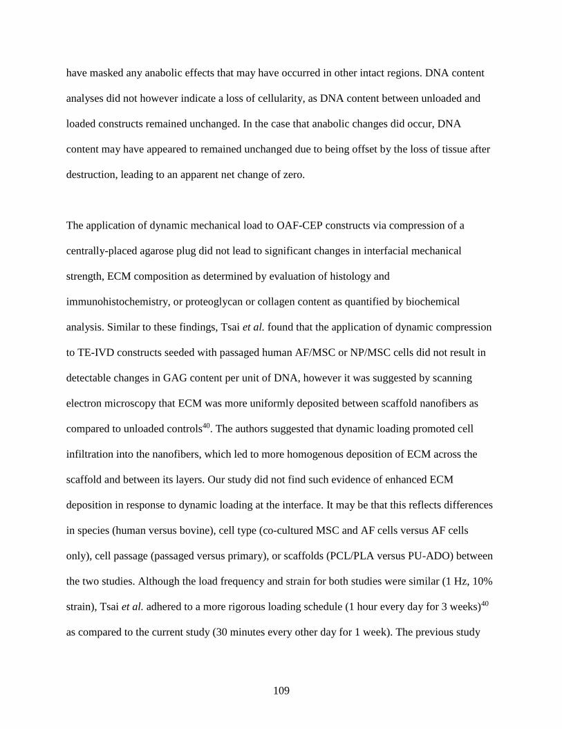
109
have masked any anabolic effects that may have occurred in other intact regions. DNA content
analyses did not however indicate a loss of cellularity, as DNA content between unloaded and
loaded constructs remained unchanged. In the case that anabolic changes did occur, DNA
content may have appeared to remained unchanged due to being offset by the loss of tissue after
destruction, leading to an apparent net change of zero.
The application of dynamic mechanical load to OAF-CEP constructs via compression of a
centrally-placed agarose plug did not lead to significant changes in interfacial mechanical
strength, ECM composition as determined by evaluation of histology and
immunohistochemistry, or proteoglycan or collagen content as quantified by biochemical
analysis. Similar to these findings, Tsai et al. found that the application of dynamic compression
to TE-IVD constructs seeded with passaged human AF/MSC or NP/MSC cells did not result in
detectable changes in GAG content per unit of DNA, however it was suggested by scanning
electron microscopy that ECM was more uniformly deposited between scaffold nanofibers as
compared to unloaded controls40. The authors suggested that dynamic loading promoted cell
infiltration into the nanofibers, which led to more homogenous deposition of ECM across the
scaffold and between its layers. Our study did not find such evidence of enhanced ECM
deposition in response to dynamic loading at the interface. It may be that this reflects differences
in species (human versus bovine), cell type (co-cultured MSC and AF cells versus AF cells
only), cell passage (passaged versus primary), or scaffolds (PCL/PLA versus PU-ADO) between
the two studies. Although the load frequency and strain for both studies were similar (1 Hz, 10%
strain), Tsai et al. adhered to a more rigorous loading schedule (1 hour every day for 3 weeks)40
as compared to the current study (30 minutes every other day for 1 week). The previous study
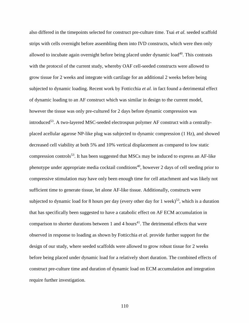
110
also differed in the timepoints selected for construct pre-culture time. Tsai et al. seeded scaffold
strips with cells overnight before assembling them into IVD constructs, which were then only
allowed to incubate again overnight before being placed under dynamic load40. This contrasts
with the protocol of the current study, whereby OAF cell-seeded constructs were allowed to
grow tissue for 2 weeks and integrate with cartilage for an additional 2 weeks before being
subjected to dynamic loading. Recent work by Fotticchia et al. in fact found a detrimental effect
of dynamic loading to an AF construct which was similar in design to the current model,
however the tissue was only pre-cultured for 2 days before dynamic compression was
introduced53. A two-layered MSC-seeded electrospun polymer AF construct with a centrally-
placed acellular agarose NP-like plug was subjected to dynamic compression (1 Hz), and showed
decreased cell viability at both 5% and 10% vertical displacement as compared to low static
compression controls53. It has been suggested that MSCs may be induced to express an AF-like
phenotype under appropriate media cocktail conditions40, however 2 days of cell seeding prior to
compressive stimulation may have only been enough time for cell attachment and was likely not
sufficient time to generate tissue, let alone AF-like tissue. Additionally, constructs were
subjected to dynamic load for 8 hours per day (every other day for 1 week)53, which is a duration
that has specifically been suggested to have a catabolic effect on AF ECM accumulation in
comparison to shorter durations between 1 and 4 hours41. The detrimental effects that were
observed in response to loading as shown by Fotticchia et al. provide further support for the
design of our study, where seeded scaffolds were allowed to grow robust tissue for 2 weeks
before being placed under dynamic load for a relatively short duration. The combined effects of
construct pre-culture time and duration of dynamic load on ECM accumulation and integration
require further investigation.
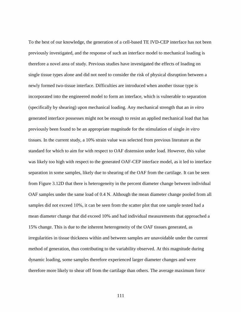
111
To the best of our knowledge, the generation of a cell-based TE IVD-CEP interface has not been
previously investigated, and the response of such an interface model to mechanical loading is
therefore a novel area of study. Previous studies have investigated the effects of loading on
single tissue types alone and did not need to consider the risk of physical disruption between a
newly formed two-tissue interface. Difficulties are introduced when another tissue type is
incorporated into the engineered model to form an interface, which is vulnerable to separation
(specifically by shearing) upon mechanical loading. Any mechanical strength that an in vitro
generated interface possesses might not be enough to resist an applied mechanical load that has
previously been found to be an appropriate magnitude for the stimulation of single in vitro
tissues. In the current study, a 10% strain value was selected from previous literature as the
standard for which to aim for with respect to OAF distension under load. However, this value
was likely too high with respect to the generated OAF-CEP interface model, as it led to interface
separation in some samples, likely due to shearing of the OAF from the cartilage. It can be seen
from Figure 3.12D that there is heterogeneity in the percent diameter change between individual
OAF samples under the same load of 0.4 N. Although the mean diameter change pooled from all
samples did not exceed 10%, it can be seen from the scatter plot that one sample tested had a
mean diameter change that did exceed 10% and had individual measurements that approached a
15% change. This is due to the inherent heterogeneity of the OAF tissues generated, as
irregularities in tissue thickness within and between samples are unavoidable under the current
method of generation, thus contributing to the variability observed. At this magnitude during
dynamic loading, some samples therefore experienced larger diameter changes and were
therefore more likely to shear off from the cartilage than others. The average maximum force
112
values from the axial tensile testing of 2-week and 4-week OAF-CEP constructs were lower than
the 0.4 N force selected for dynamic compression of the central agarose plug (~0.1 N for 2-week
and ~0.2 N for 4-week, data not shown). Although axial tensile failure results do not translate
into values for shear strength at the interface, it might be of interest to use these failure values in
the determination of optimal loading conditions. Specifically, load values of no more than 0.1 N
to 0.2 N should be tested in order to minimize the risk of ECM disruption at the interface.
A centrally-placed agarose plug has been used in a previous study to model the NP within an
electrospun multilamellar AF construct155 and has been suggested by mathematical modeling to
be an appropriate material for dynamic compression within the current AF model system (Rok
2017, unpublished). The agarose plug used in our study was larger in height than the OAF by
approximately 2 mm, so as to only investigate the effects of OAF lateral expansion caused by
agarose (NP) compression. In generating the constructs, OAF tissues were not always attached in
the centre of the cartilage, and were sometimes skewed closer to the edge of the membrane
insert. The jig indenter surface area used in our study was therefore designed to be small enough
to fit within the plastic insert and large enough to cover the entire surface of the OAF construct,
which ensured that the entire surface area of the agarose plug would be contacted by the indenter
regardless of the OAF’s position atop the cartilage. Thus, the application of force to the agarose
plug across all samples was assumed to be uniform. However, small differences between
individual agarose plug height dimensions as a result of variability between batches may have
led to variable applications of outward force to OAF tissues. Additionally, the forces applied in
the current model system did not fully model what occurs in the native IVD. Axial compression
applied to the agarose plug led to radial tension and shear at the in vitro OAF-CEP interface,
113
whereas the native tissue also experiences compression and torsion. The current loading
conditions were selected in attempt to tease out the potential roles of different forces (i.e. tension
and shear may have had different effects on the interface compared to radial tension, shear and
compression combined). The unexpected outcome of interface disruption prevented any potential
effects from being found. It is possible that this focus on only tension and shear may have
favoured interface disruption. Further optimization of loading conditions is required when it
comes to the mechanical stimulation of a two-tissue interface.
4.3 Recommendations for Future Work
Despite modeling particular structural and compositional features, this model did not fully mimic
native interface characteristics. The interface region of the native AF and CEP demonstrates
anchorage of the relatively soft AF collagen fibres to the hard VB100,102. The CEP is the
intermediate tissue through which this occurs. AF fibril interconnections with the CEP
cartilaginous phase are strengthened by the CEP mineralized zone. Specifically, these
characteristics contribute to the mechanical strength at this interface100,102, and provide a clear
direction for subsequent future work. As the major structural difference between the current
OAF-CEP model and the native interface is the absence of AF fibril insertion through a
mineralized cartilage layer that is integrated with the underlying bone63, it is anticipated that an
enhancement of mechanical properties could be achieved in future iterations of the model that
include these components.
The current model utilized OAF cells only for the generation of in vitro tissue on PU-ADO
scaffolds, which was confirmed by immunostaining to compositionally resemble native OAF
114
tissue with respect to the presence of collagen type I and the lack of collagen type II
(Supplemental Figure S7). The native AF is composed of distinct inner and outer regions, each
differing in their respective ratios of collagen type I to collagen type II. Previous work on the
current AF culture system has shown that DMEM supplemented with dexamethasone, pyruvate,
proline, and ITS maintained the distinct phenotypes of both OAF and IAF cells31. Future work
should use this system to determine if in vitro formed AF tissue containing both IAF and OAF
components will integrate to form an interface with CEP-like tissues as well.
The interface that was successfully formed between OAF and CEP-like tissues only represents
one amongst five other interfaces within the IVD space: IAF-NP, IAF-OAF, NP-CEP, IAF-CEP,
and CEP-VB. Previous work has generated a biphasic in vitro bovine IAF-NP interface that
accumulated mechanical strength over time in co-culture194, as well as a biphasic cartilage-CPP
construct that showed improved mechanical properties upon in vivo implantation225. These along
with the current study demonstrate promise for successful generation of the other necessary
biphasic IVD interface models that must be developed in order to build a complete multiphasic
implant model consisting of distinct and integrated parts. Determining if cartilage grown on CPP
can integrate similarly with multilamellated OAF tissues will be of particular interest, as a hard
bone material will be part of an eventual implant model. Incorporation of a mineralized zone
within the cartilage layer will also be necessary. Mineralization of in vitro cartilage tissues may
be induced in a similar manner to what occurs in vivo by the addition of β-glycerophosphate into
the media cocktail226. The presence of both NP and AF cell-seeded components in a future IVD-
cartilage model may also provide insight into the effect of dynamic loading at the interface(s), as
crosstalk between cells might influence outcomes with respect to mechanical loading.
115
The current study only examined the presence of three major ECM molecules known to be
present in native AF and CEP tissue: collagen type I, collagen type II, and aggrecan. Other ECM
molecules such as collagen type VI (a potential marker of fibrocartilage96) and small leucine-rich
proteoglycans (SLRPs; e.g. decorin, biglycan, and fibromodulin; involved in collagen
fibrillogenesis) have been reported in the developing and mature native AF, CEP, and interface
regions72,73. Fibromodulin may be of particular interest, as it was reported to occur in the
developing AF-CEP region during embryogenesis and hence might play a specific role in tissue
integration and organization at the interface73. Elastin fibres are also present at the IVD-CEP
interface104. Future work should therefore further characterize the in vitro OAF-CEP model with
a wider panel of ECM components in mind.
Based on the outcomes of the current study it is also recommended that dynamic loading be
applied to an in vitro OAF-CEP construct at a later timepoint, perhaps after 3 or 4 weeks of static
co-culture. The current protocol applied dynamic compression to a 2-week old construct, before
there was visible proteoglycan (aggrecan) diffusion past the interface and into the OAF region.
This led to the destruction of the interface in some samples. Two weeks may not have been
enough time to allow for sufficient ECM synthesis and subsequent remodeling to occur between
the in vitro tissues, and too early to introduce a mechanical stimulus to see any enhancing effect.
Aggrecan has been found to protect collagen against proteolytic degradation227 and therefore
might have a protective effect against disruption of collagen fibers at the interface during
mechanical loading. This further supports the rationale for application of dynamic loading at a
later timepoint, by which time aggrecan may be more abundant in the interfacial OAF region. A
116
prolonged period of overall ECM deposition (i.e. 4 weeks) may also be required before
mechanical loading would be able to induce anabolic rather catabolic, necrotic and/or apoptotic
responses. Establishing optimized loading conditions will be required, specifically for an
interface model which has little mechanical strength, along with the optimization of sufficient
time for remodelling to occur post-loading. Other parameters such as duration of cyclic
compression and timing of application may need to be considered. Future dynamic compression
may also consider applying dynamic load to the construct in a fashion that more closely mimics
what occurs in vivo (i.e. simultaneous compression, radial tension and shear). When loading
conditions have been optimized, other forces such as torsion and axial tension may be introduced
to the model.
Although generation of a small-scale model is required as a first step towards generating a
clinically relevant implant, it is necessary to consider the feasibility of scaling up. The outer
diameter of the OAF in the current interface model was approximately 7 mm. Gullbrand et al.
recently investigated rabbit (“medium”) and human-sized (“large”) IVD constructs generated
from IVD cell-seeded angle-ply nanofibrous polymer scaffolds228. Although the large constructs
matured compositionally in vitro, the medium AF constructs showed higher GAG and collagen
content compared to large constructs. Therefore, effective scale-up of implant constructs that
structurally mimic the native IVD remains challenging and should be considered in future work.
4.4 Conclusions
In summary, this is the first study, to our knowledge, that has conceived, established and
characterized a tissue-engineered AF-CEP interface that simultaneously 1) models the AF multi-
117
lamellated angle-ply structure and 2) has an integrated in vitro cartilage layer to yield an
interface capable of reproducing important ECM features within an IVD model. Increased
interfacial mechanical strength can be achieved by increasing in vitro culture time. The ability to
generate integration between in vitro OAF and cartilage tissues is one step towards the
development of a fully integrated, multiphasic, biomimetic biological IVD implant. This model
can be used to investigate approaches towards enhancing integration of such tissue for in vivo
applications. Future work on this model will focus on inducing mineralization in the deep zone
of the cartilage layer in order to further mimic the native OAF-CEP-VB region. Further
investigation is required to produce enhanced strength at the construct interface.
118
CHAPTER 5: REFERENCES
1 Rodrigues, S. A., Thambyah, A. & Broom, N. D. A multiscale structural investigation of
the annulus-endplate anchorage system and its mechanisms of failure. Spine J 15, 405-
416, doi:10.1016/j.spinee.2014.12.144 (2015).
2 Maroudas, A., Stockwell, R. A., Nachemson, A. & Urban, J. Factors involved in the
nutrition of the human lumbar intervertebral disc: cellularity and diffusion of glucose in
vitro. J Anat 120, 113-130 (1975).
3 Nachemson, A., Lewin, T., Maroudas, A. & Freeman, M. A. In vitro diffusion of dye
through the end-plates and the annulus fibrosus of human lumbar inter-vertebral discs.
Acta Orthop Scand 41, 589-607 (1970).
4 Oki, S. et al. Scanning electron microscopic observations of the vascular structure of
vertebral end-plates in rabbits. J Orthop Res 12, 447-449, doi:10.1002/jor.1100120318
(1994).
5 Luoma, K. et al. Low back pain in relation to lumbar disc degeneration. Spine (Phila Pa
1976) 25, 487-492 (2000).
6 Videman, T. et al. Associations between back pain history and lumbar MRI findings.
Spine (Phila Pa 1976) 28, 582-588, doi:10.1097/01.brs.0000049905.44466.73 (2003).
7 Smith, L. J., Nerurkar, N. L., Choi, K. S., Harfe, B. D. & Elliott, D. M. Degeneration and
regeneration of the intervertebral disc: lessons from development. Dis Model Mech 4, 31-
41, doi:10.1242/dmm.006403 (2011).
8 van den Eerenbeemt, K. D., Ostelo, R. W., van Royen, B. J., Peul, W. C. & van Tulder,
M. W. Total disc replacement surgery for symptomatic degenerative lumbar disc disease:
119
a systematic review of the literature. Eur Spine J 19, 1262-1280, doi:10.1007/s00586-
010-1445-3 (2010).
9 Miller, J. et al. Adjacent Level Degeneration: Bryan Total Disc Arthroplasty Versus
Anterior Cervical Discectomy and Fusion. Clin Spine Surg 31, E98-e101,
doi:10.1097/bsd.0000000000000598 (2018).
10 Yoshikawa, T., Ueda, Y., Miyazaki, K., Koizumi, M. & Takakura, Y. Disc regeneration
therapy using marrow mesenchymal cell transplantation: a report of two case studies.
Spine (Phila Pa 1976) 35, E475-480, doi:10.1097/BRS.0b013e3181cd2cf4 (2010).
11 Orozco, L. et al. Intervertebral disc repair by autologous mesenchymal bone marrow
cells: a pilot study. Transplantation 92, 822-828, doi:10.1097/TP.0b013e3182298a15
(2011).
12 Noriega, D. C. et al. Intervertebral Disc Repair by Allogeneic Mesenchymal Bone
Marrow Cells: A Randomized Controlled Trial. Transplantation 101, 1945-1951,
doi:10.1097/tp.0000000000001484 (2017).
13 Coric, D., Pettine, K., Sumich, A. & Boltes, M. O. Prospective study of disc repair with
allogeneic chondrocytes presented at the 2012 Joint Spine Section Meeting. J Neurosurg
Spine 18, 85-95, doi:10.3171/2012.10.spine12512 (2013).
14 Meisel, H. J. et al. Clinical experience in cell-based therapeutics: disc chondrocyte
transplantation A treatment for degenerated or damaged intervertebral disc. Biomol Eng
24, 5-21, doi:10.1016/j.bioeng.2006.07.002 (2007).
15 Gruber, H. E. et al. Human adipose-derived mesenchymal stem cells: direction to a
phenotype sharing similarities with the disc, gene expression profiling, and coculture
120
with human annulus cells. Tissue Eng Part A 16, 2843-2860,
doi:10.1089/ten.TEA.2009.0709 (2010).
16 Gebraad, A. W. H., Miettinen, S., Grijpma, D. W. & Haimi, S. P. Human Adipose Stem
Cells in Chondrogenic Differentiation Medium without Growth Factors Differentiate
Towards Annulus Fibrosus Phenotype In Vitro. Macromolecular Symposia 334, 49-56,
doi:10.1002/masy.201300104 (2013).
17 Clarke, L. E. et al. Growth differentiation factor 6 and transforming growth factor-beta
differentially mediate mesenchymal stem cell differentiation, composition, and
micromechanical properties of nucleus pulposus constructs. Arthritis Res Ther 16, R67,
doi:10.1186/ar4505 (2014).
18 Mwale, F., Roughley, P. & Antoniou, J. Distinction between the extracellular matrix of
the nucleus pulposus and hyaline cartilage: a requisite for tissue engineering of
intervertebral disc. Eur Cell Mater 8, 58-63; discussion 63-54 (2004).
19 Lv, F. et al. In search of nucleus pulposus-specific molecular markers. Rheumatology
(Oxford) 53, 600-610, doi:10.1093/rheumatology/ket303 (2014).
20 Choy, A. T. & Chan, B. P. A Structurally and Functionally Biomimetic Biphasic Scaffold
for Intervertebral Disc Tissue Engineering. PLoS One 10, e0131827,
doi:10.1371/journal.pone.0131827 (2015).
21 Bowles, R. D., Williams, R. M., Zipfel, W. R. & Bonassar, L. J. Self-assembly of aligned
tissue-engineered annulus fibrosus and intervertebral disc composite via collagen gel
contraction. Tissue Eng Part A 16, 1339-1348, doi:10.1089/ten.TEA.2009.0442 (2010).
121
22 Bhunia, B. K., Kaplan, D. L. & Mandal, B. B. Silk-based multilayered angle-ply annulus
fibrosus construct to recapitulate form and function of the intervertebral disc. Proc Natl
Acad Sci U S A 115, 477-482, doi:10.1073/pnas.1715912115 (2018).
23 Yang, J. et al. Reverse Reconstruction and Bioprinting of Bacterial Cellulose-Based
Functional Total Intervertebral Disc for Therapeutic Implantation. Small 14,
doi:10.1002/smll.201702582 (2018).
24 Nerurkar, N. L. et al. Nanofibrous biologic laminates replicate the form and function of
the annulus fibrosus. Nat Mater 8, 986-992, doi:10.1038/nmat2558 (2009).
25 Nerurkar, N. L., Elliott, D. M. & Mauck, R. L. Mechanics of oriented electrospun
nanofibrous scaffolds for annulus fibrosus tissue engineering. J Orthop Res 25, 1018-
1028, doi:10.1002/jor.20384 (2007).
26 Martin, J. T. et al. Translation of an Engineered Nanofibrous Disc-like Angle Ply
Structure for Intervertebral Disc Replacement in a Small Animal Model. Acta
biomaterialia 10, 2473-2481, doi:10.1016/j.actbio.2014.02.024 (2014).
27 Martin, J. T. et al. In vivo performance of an acellular disc-like angle ply structure
(DAPS) for total disc replacement in a small animal model. J Orthop Res 35, 23-31,
doi:10.1002/jor.23310 (2017).
28 Martin, J. T. et al. In Vitro Maturation and In Vivo Integration and Function of an
Engineered Cell-Seeded Disc-like Angle Ply Structure (DAPS) for Total Disc
Arthroplasty. Sci Rep 7, 15765, doi:10.1038/s41598-017-15887-4 (2017).
29 Liu, C. et al. The effect of the fibre orientation of electrospun scaffolds on the matrix
production of rabbit annulus fibrosus-derived stem cells. Bone Res 3, 15012,
doi:10.1038/boneres.2015.12 (2015).
122
30 Iu, J., Santerre, J. P. & Kandel, R. A. Inner and outer annulus fibrosus cells exhibit
differentiated phenotypes and yield changes in extracellular matrix protein composition
in vitro on a polycarbonate urethane scaffold. Tissue Eng Part A 20, 3261-3269,
doi:10.1089/ten.TEA.2013.0777 (2014).
31 Iu, J., Santerre, J. P. & Kandel, R. A. Towards Engineering Distinct Multi-lamellated
Outer and Inner Annulus Fibrosus Tissues. J Orthop Res, doi:10.1002/jor.23793 (2017).
32 Gilbert, H. T., Hoyland, J. A., Freemont, A. J. & Millward-Sadler, S. J. The involvement
of interleukin-1 and interleukin-4 in the response of human annulus fibrosus cells to
cyclic tensile strain: an altered mechanotransduction pathway with degeneration. Arthritis
Res Ther 13, R8, doi:10.1186/ar3229 (2011).
33 Gilbert, H. T., Hoyland, J. A. & Millward-Sadler, S. J. The response of human anulus
fibrosus cells to cyclic tensile strain is frequency-dependent and altered with disc
degeneration. Arthritis Rheum 62, 3385-3394, doi:10.1002/art.27643 (2010).
34 Li, S., Jia, X., Duance, V. C. & Blain, E. J. The effects of cyclic tensile strain on the
organisation and expression of cytoskeletal elements in bovine intervertebral disc cells:
an in vitro study. Eur Cell Mater 21, 508-522 (2011).
35 Li, P. et al. Matrix homeostasis within the immature annulus fibrosus depends on the
frequency of dynamic compression: a study based on the self-developed mechanically
active bioreactor. Biomech Model Mechanobiol 16, 385-394, doi:10.1007/s10237-016-
0823-0 (2017).
36 Kasra, M. et al. Frequency response of pig intervertebral disc cells subjected to dynamic
hydrostatic pressure. J Orthop Res 24, 1967-1973, doi:10.1002/jor.20253 (2006).
123
37 Kasra, M. et al. Effect of dynamic hydrostatic pressure on rabbit intervertebral disc cells.
J Orthop Res 21, 597-603, doi:10.1016/S0736-0266(03)00027-5 (2003).
38 Davisson, T., Kunig, S., Chen, A., Sah, R. & Ratcliffe, A. Static and dynamic
compression modulate matrix metabolism in tissue engineered cartilage. J Orthop Res 20,
842-848, doi:10.1016/S0736-0266(01)00160-7 (2002).
39 Hudson, K. D., Mozia, R. I. & Bonassar, L. J. Dose-dependent response of tissue-
engineered intervertebral discs to dynamic unconfined compressive loading. Tissue Eng
Part A 21, 564-572, doi:10.1089/ten.TEA.2014.0174 (2015).
40 Tsai, T. L., Nelson, B. C., Anderson, P. A., Zdeblick, T. A. & Li, W. J. Intervertebral disc
and stem cells cocultured in biomimetic extracellular matrix stimulated by cyclic
compression in perfusion bioreactor. Spine J 14, 2127-2140,
doi:10.1016/j.spinee.2013.11.062 (2014).
41 Li, P. et al. Biological Responses of the Immature Annulus Fibrosus to Dynamic
Compression in a Disc Perfusion Culture. Cells Tissues Organs 202, 296-306,
doi:10.1159/000446363 (2016).
42 Hee, H. T., Zhang, J. & Wong, H. K. An in vitro study of dynamic cyclic compressive
stress on human inner annulus fibrosus and nucleus pulposus cells. The Spine Journal 10,
795-801, doi:https://doi.org/10.1016/j.spinee.2010.06.009 (2010).
43 Sharma, G., Saxena, R. K. & Mishra, P. Differential effects of cyclic and static pressure
on biochemical and morphological properties of chondrocytes from articular cartilage.
Clin Biomech (Bristol, Avon) 22, 248-255, doi:10.1016/j.clinbiomech.2006.09.008
(2007).
124
44 Korecki, C. L., Kuo, C. K., Tuan, R. S. & Iatridis, J. C. Intervertebral disc cell response
to dynamic compression is age and frequency dependent. J Orthop Res 27, 800-806,
doi:10.1002/jor.20814 (2009).
45 Maclean, J. J., Lee, C. R., Alini, M. & Iatridis, J. C. Anabolic and catabolic mRNA levels
of the intervertebral disc vary with the magnitude and frequency of in vivo dynamic
compression. J Orthop Res 22, 1193-1200, doi:10.1016/j.orthres.2004.04.004 (2004).
46 MacLean, J. J., Lee, C. R., Alini, M. & Iatridis, J. C. The effects of short-term load
duration on anabolic and catabolic gene expression in the rat tail intervertebral disc. J
Orthop Res 23, 1120-1127, doi:10.1016/j.orthres.2005.01.020 (2005).
47 Wang, D. L., Jiang, S. D. & Dai, L. Y. Biologic response of the intervertebral disc to
static and dynamic compression in vitro. Spine (Phila Pa 1976) 32, 2521-2528,
doi:10.1097/BRS.0b013e318158cb61 (2007).
48 Korecki, C. L., MacLean, J. J. & Iatridis, J. C. Dynamic compression effects on
intervertebral disc mechanics and biology. Spine (Phila Pa 1976) 33, 1403-1409,
doi:10.1097/BRS.0b013e318175cae7 (2008).
49 Waldman, S. D., Spiteri, C. G., Grynpas, M. D., Pilliar, R. M. & Kandel, R. A. Long-
term intermittent compressive stimulation improves the composition and mechanical
properties of tissue-engineered cartilage. Tissue Eng 10, 1323-1331,
doi:10.1089/ten.2004.10.1633 (2004).
50 Waldman, S. D., Couto, D. C., Grynpas, M. D., Pilliar, R. M. & Kandel, R. A. A single
application of cyclic loading can accelerate matrix deposition and enhance the properties
of tissue-engineered cartilage. Osteoarthritis Cartilage 14, 323-330,
doi:10.1016/j.joca.2005.10.007 (2006).
125
51 Rannou, F. et al. Cyclic tensile stretch modulates proteoglycan production by
intervertebral disc annulus fibrosus cells through production of nitrite oxide. J Cell
Biochem 90, 148-157, doi:10.1002/jcb.10608 (2003).
52 Sowa, G. & Agarwal, S. Cyclic tensile stress exerts a protective effect on intervertebral
disc cells. Am J Phys Med Rehabil 87, 537-544, doi:10.1097/PHM.0b013e31816197ee
(2008).
53 Fotticchia, A., Demirci, E., Lenardi, C. & Liu, Y. Cellular Response to Cyclic
Compression of Tissue Engineered Intervertebral Disk Constructs Composed of
Electrospun Polycaprolactone. Journal of Biomechanical Engineering 140, 061002-
061002-061009, doi:10.1115/1.4039307 (2018).
54 Gruber, H. E. et al. Vertebral endplate architecture and vascularization: application of
micro-computerized tomography, a vascular tracer, and immunocytochemistry in
analyses of disc degeneration in the aging sand rat. Spine (Phila Pa 1976) 30, 2593-2600
(2005).
55 Martins, D. E. et al. Changes in human intervertebral disc biochemical composition and
bony end plates between middle and old age. PLoS One 13, e0203932,
doi:10.1371/journal.pone.0203932 (2018).
56 Iatridis, J. C., MacLean, J. J., O'Brien, M. & Stokes, I. A. Measurements of proteoglycan
and water content distribution in human lumbar intervertebral discs. Spine (Phila Pa
1976) 32, 1493-1497, doi:10.1097/BRS.0b013e318067dd3f (2007).
57 Roberts, S., Menage, J. & Urban, J. P. Biochemical and structural properties of the
cartilage end-plate and its relation to the intervertebral disc. Spine (Phila Pa 1976) 14,
166-174 (1989).
126
58 Hayes, A. J., Benjamin, M. & Ralphs, J. R. Extracellular matrix in development of the
intervertebral disc. Matrix Biol 20, 107-121 (2001).
59 Lodish , H. et al. in Molecular Cell Biology. 4th edition. Section 22.3, Collagen: The
Fibrous Proteins of the Matrix. Available from:
https://www.ncbi.nlm.nih.gov/books/NBK21582/ (New York: W. H. Freeman, 2000).
60 Culav, E. M., Clark, C. H. & Merrilees, M. J. Connective tissues: matrix composition and
its relevance to physical therapy. Phys Ther 79, 308-319 (1999).
61 Roberts, S., Menage, J., Duance, V. & Wotton, S. F. Type III collagen in the
intervertebral disc. Histochem J 23, 503-508 (1991).
62 Melrose, J., Smith, S. M., Appleyard, R. C. & Little, C. B. Aggrecan, versican and type
VI collagen are components of annular translamellar crossbridges in the intervertebral
disc. Eur Spine J 17, 314-324, doi:10.1007/s00586-007-0538-0 (2008).
63 Nosikova, Y. S., Santerre, J. P., Grynpas, M., Gibson, G. & Kandel, R. A.
Characterization of the annulus fibrosus-vertebral body interface: identification of new
structural features. J Anat 221, 577-589, doi:10.1111/j.1469-7580.2012.01537.x (2012).
64 Sivan, S. S., Wachtel, E. & Roughley, P. Structure, function, aging and turnover of
aggrecan in the intervertebral disc. Biochim Biophys Acta 1840, 3181-3189,
doi:10.1016/j.bbagen.2014.07.013 (2014).
65 Jay, G. D. & Waller, K. A. The biology of Lubricin: Near frictionless joint motion.
Matrix Biology 39, 17-24, doi:https://doi.org/10.1016/j.matbio.2014.08.008 (2014).
66 Shine, K. M., Simson, J. A. & Spector, M. Lubricin distribution in the human
intervertebral disc. J Bone Joint Surg Am 91, 2205-2212, doi:10.2106/JBJS.H.01344
(2009).

127
67 Shine, K. M. & Spector, M. The presence and distribution of lubricin in the caprine
intervertebral disc. J Orthop Res 26, 1398-1406, doi:10.1002/jor.20614 (2008).
68 Teeple, E. et al. Coefficients of friction, lubricin, and cartilage damage in the anterior
cruciate ligament-deficient guinea pig knee. J Orthop Res 26, 231-237,
doi:10.1002/jor.20492 (2008).
69 Teeple, E. et al. Lubricin deficiency in the murine lumbar intervertebral disc results in
elevated torsional apparent modulus. J Biomech 48, 2210-2213,
doi:10.1016/j.jbiomech.2015.03.029 (2015).
70 Peacock, A. Observations on the prenatal development of the intervertebral disc in man. J
Anat 85, 260-274 (1951).
71 Rufai, A., Benjamin, M. & Ralphs, J. R. The development of fibrocartilage in the rat
intervertebral disc. Anat Embryol (Berl) 192, 53-62 (1995).
72 Hayes, A. J., Benjamin, M. & Ralphs, J. R. Role of actin stress fibres in the development
of the intervertebral disc: cytoskeletal control of extracellular matrix assembly. Dev Dyn
215, 179-189, doi:10.1002/(sici)1097-0177(199907)215:3<179::aid-aja1>3.0.co;2-q
(1999).
73 Hayes, A. J., Isaacs, M. D., Hughes, C., Caterson, B. & Ralphs, J. R. Collagen
fibrillogenesis in the development of the annulus fibrosus of the intervertebral disc. Eur
Cell Mater 22, 226-241 (2011).
74 Hashizume, H. Three-dimensional architecture and development of lumber intervertebral
discs. Acta Med Okayama 34, 301-314, doi:10.18926/AMO/30545 (1980).
128
75 Rodrigues, S. A., Thambyah, A. & Broom, N. D. How maturity influences annulus-
endplate integration in the ovine intervertebral disc: a micro- and ultra-structural study. J
Anat 230, 152-164, doi:10.1111/joa.12536 (2017).
76 Khoshnoodi, J., Pedchenko, V. & Hudson, B. G. Mammalian collagen IV. Microsc Res
Tech 71, 357-370, doi:10.1002/jemt.20564 (2008).
77 Melrose, J., Ghosh, P. & Taylor, T. K. A comparative analysis of the differential spatial
and temporal distributions of the large (aggrecan, versican) and small (decorin, biglycan,
fibromodulin) proteoglycans of the intervertebral disc. J Anat 198, 3-15 (2001).
78 Urban, J. P. G., Roberts, S. & Ralphs, J. R. The Nucleus of the Intervertebral Disc from
Development to Degeneration 1. American Zoologist 40, 53-61, doi:10.1668/0003-
1569(2000)040[0053:TNOTID]2.0.CO;2 (2000).
79 Inoue, H. Three-dimensional architecture of lumbar intervertebral discs. Spine (Phila Pa
1976) 6, 139-146 (1981).
80 Wade, K. R., Robertson, P. A. & Broom, N. D. A fresh look at the nucleus-endplate
region: new evidence for significant structural integration. Eur Spine J 20, 1225-1232,
doi:10.1007/s00586-011-1704-y (2011).
81 Yu, J., Winlove, P. C., Roberts, S. & Urban, J. P. Elastic fibre organization in the
intervertebral discs of the bovine tail. J Anat 201, 465-475 (2002).
82 Hunter, C. J., Matyas, J. R. & Duncan, N. A. Cytomorphology of notochordal and
chondrocytic cells from the nucleus pulposus: a species comparison. J Anat 205, 357-
362, doi:10.1111/j.0021-8782.2004.00352.x (2004).
129
83 Hunter, C. J., Matyas, J. R. & Duncan, N. A. The three-dimensional architecture of the
notochordal nucleus pulposus: novel observations on cell structures in the canine
intervertebral disc. J Anat 202, 279-291 (2003).
84 Chen, J., Yan, W. & Setton, L. A. Molecular phenotypes of notochordal cells purified
from immature nucleus pulposus. Eur Spine J 15 Suppl 3, S303-311,
doi:10.1007/s00586-006-0088-x (2006).
85 Purmessur, D. et al. Dynamic pressurization induces transition of notochordal cells to a
mature phenotype while retaining production of important patterning ligands from
development. Arthritis Res Ther 15, R122 (2013).
86 Kim, J. H. et al. Differentiation of intervertebral notochordal cells through live automated
cell imaging system in vitro. Spine (Phila Pa 1976) 34, 2486-2493,
doi:10.1097/BRS.0b013e3181b26ed1 (2009).
87 Trout, J. J., Buckwalter, J. A., Moore, K. C. & Landas, S. K. Ultrastructure of the human
intervertebral disc. I. Changes in notochordal cells with age. Tissue Cell 14, 359-369
(1982).
88 Yang, F., Leung, V. Y., Luk, K. D., Chan, D. & Cheung, K. M. Injury-induced sequential
transformation of notochordal nucleus pulposus to chondrogenic and fibrocartilaginous
phenotype in the mouse. J Pathol 218, 113-121, doi:10.1002/path.2519 (2009).
89 Cassidy, J. J., Hiltner, A. & Baer, E. Hierarchical structure of the intervertebral disc.
Connect Tissue Res 23, 75-88 (1989).
90 Bruehlmann, S. B., Rattner, J. B., Matyas, J. R. & Duncan, N. A. Regional variations in
the cellular matrix of the annulus fibrosus of the intervertebral disc. J Anat 201, 159-171
(2002).
130
91 Gruber, H. E., Ingram, J., Hoelscher, G. L., Norton, H. J. & Hanley, E. N. Cell polarity in
the anulus of the human intervertebral disc: morphologic, immunocytochemical, and
molecular evidence. Spine (Phila Pa 1976) 32, 1287-1294,
doi:10.1097/BRS.0b013e31805931d8 (2007).
92 Tavakoli, J., Elliott, D. M. & Costi, J. J. The ultra-structural organization of the elastic
network in the intra- and inter-lamellar matrix of the intervertebral disc. Acta
Biomaterialia 58, 269-277, doi:https://doi.org/10.1016/j.actbio.2017.05.036 (2017).
93 Tavakoli, J. & Costi, J. J. New findings confirm the viscoelastic behaviour of the inter-
lamellar matrix of the disc annulus fibrosus in radial and circumferential directions of
loading. Acta Biomater 71, 411-419, doi:10.1016/j.actbio.2018.03.015 (2018).
94 Schollum, M. L., Robertson, P. A. & Broom, N. D. A microstructural investigation of
intervertebral disc lamellar connectivity: detailed analysis of the translamellar bridges. J
Anat 214, 805-816, doi:10.1111/j.1469-7580.2009.01076.x (2009).
95 Smith, L. J. & Elliott, D. M. Formation of lamellar cross bridges in the annulus fibrosus
of the intervertebral disc is a consequence of vascular regression. Matrix Biol 30, 267-
274, doi:10.1016/j.matbio.2011.03.009 (2011).
96 Carvalho, H. F., Felisbino, S. L., Keene, D. R. & Vogel, K. G. Identification, content, and
distribution of type VI collagen in bovine tendons. Cell Tissue Res 325, 315-324,
doi:10.1007/s00441-006-0161-0 (2006).
97 Vogel, K. G. & Peters, J. A. Histochemistry defines a proteoglycan-rich layer in bovine
flexor tendon subjected to bending. J Musculoskelet Neuronal Interact 5, 64-69 (2005).
131
98 Moon, S. M. et al. Evaluation of intervertebral disc cartilaginous endplate structure using
magnetic resonance imaging. Eur Spine J 22, 1820-1828, doi:10.1007/s00586-013-2798-
1 (2013).
99 Paietta, R. C., Burger, E. L. & Ferguson, V. L. Mineralization and collagen orientation
throughout aging at the vertebral endplate in the human lumbar spine. J Struct Biol 184,
310-320, doi:10.1016/j.jsb.2013.08.011 (2013).
100 Rodrigues, S. A., Wade, K. R., Thambyah, A. & Broom, N. D. Micromechanics of
annulus-end plate integration in the intervertebral disc. Spine J 12, 143-150,
doi:10.1016/j.spinee.2012.01.003 (2012).
101 Junhui, L. et al. Anchorage of annulus fibrosus within the vertebral endplate with
reference to disc herniation. Microsc Res Tech 78, 754-760, doi:10.1002/jemt.22536
(2015).
102 Sapiee, N. H., Thambyah, A., Robertson, P. A. & Broom, N. D. New evidence for
structural integration across the cartilage-vertebral endplate junction and its relation to
herniation. Spine J, doi:10.1016/j.spinee.2018.08.013 (2018).
103 Berg-Johansen, B., Fields, A. J., Liebenberg, E. C., Li, A. & Lotz, J. C. Structure-
function relationships at the human spinal disc-vertebra interface. J Orthop Res 36, 192-
201, doi:10.1002/jor.23627 (2018).
104 Johnson, E. F., Chetty, K., Moore, I. M., Stewart, A. & Jones, W. The distribution and
arrangement of elastic fibres in the intervertebral disc of the adult human. J Anat 135,
301-309 (1982).
132
105 Arana, C. J., Diamandis, E. P. & Kandel, R. A. Cartilage tissue enhances proteoglycan
retention by nucleus pulposus cells in vitro. Arthritis Rheum 62, 3395-3403,
doi:10.1002/art.27651 (2010).
106 Haschtmann, D., Stoyanov, J. V., Gédet, P. & Ferguson, S. J. Vertebral endplate trauma
induces disc cell apoptosis and promotes organ degeneration in vitro. Eur Spine J 17,
289-299, doi:10.1007/s00586-007-0509-5 (2008).
107 Battié, M. C. & Videman, T. Lumbar disc degeneration: epidemiology and genetics.
108 Miller, J. A., Schmatz, C. & Schultz, A. B. Lumbar disc degeneration: correlation with
age, sex, and spine level in 600 autopsy specimens. Spine (Phila Pa 1976) 13, 173-178
(1988).
109 Stokes, I. A. & Iatridis, J. C. Mechanical conditions that accelerate intervertebral disc
degeneration: overload versus immobilization. Spine (Phila Pa 1976) 29, 2724-2732
(2004).
110 Antoniou, J. et al. The human lumbar intervertebral disc: evidence for changes in the
biosynthesis and denaturation of the extracellular matrix with growth, maturation, ageing,
and degeneration. J Clin Invest 98, 996-1003, doi:10.1172/jci118884 (1996).
111 Gruber, H. E. et al. Variations in aggrecan localization and gene expression patterns
characterize increasing stages of human intervertebral disk degeneration. Exp Mol Pathol
91, 534-539, doi:10.1016/j.yexmp.2011.06.001 (2011).
112 Johnson, W. E. et al. Human intervertebral disc aggrecan inhibits nerve growth in vitro.
Arthritis Rheum 46, 2658-2664, doi:10.1002/art.10585 (2002).
133
113 Sharma, A., Pilgram, T. & Wippold, F. J., 2nd. Association between annular tears and
disk degeneration: a longitudinal study. AJNR Am J Neuroradiol 30, 500-506,
doi:10.3174/ajnr.A1411 (2009).
114 Pfirrmann, C. W., Metzdorf, A., Zanetti, M., Hodler, J. & Boos, N. Magnetic resonance
classification of lumbar intervertebral disc degeneration. Spine (Phila Pa 1976) 26, 1873-
1878 (2001).
115 Brown, S. et al. A comparative evaluation of the small leucine-rich proteoglycans of
pathological human intervertebral discs. Eur Spine J 21 Suppl 2, S154-159,
doi:10.1007/s00586-012-2179-1 (2012).
116 Loreto, C., Musumeci, G., Castorina, A. & Martinez, G. Degenerative disc disease of
herniated intervertebral discs is associated with extracellular matrix remodeling,
vimentin-positive cells and cell death. Ann Anat 193, 156-162,
doi:10.1016/j.aanat.2010.12.001 (2011).
117 Le Maitre, C. L., Pockert, A., Buttle, D. J., Freemont, A. J. & Hoyland, J. A. Matrix
synthesis and degradation in human intervertebral disc degeneration. Biochem Soc Trans
35, 652-655, doi:10.1042/BST0350652 (2007).
118 Le Maitre, C. L., Hoyland, J. A. & Freemont, A. J. Catabolic cytokine expression in
degenerate and herniated human intervertebral discs: IL-1β and TNFα expression profile.
Arthritis Research & Therapy 9, R77, doi:10.1186/ar2275 (2007).
119 Emanuel, K. S. et al. Early changes in the extracellular matrix of the degenerating
intervertebral disc, assessed by Fourier transform infrared imaging. Osteoarthritis
Cartilage, doi:10.1016/j.joca.2018.06.003 (2018).
134
120 Ariga, K. et al. Mechanical stress-induced apoptosis of endplate chondrocytes in organ-
cultured mouse intervertebral discs: an ex vivo study. Spine (Phila Pa 1976) 28, 1528-
1533 (2003).
121 Lotz, J. C. & Chin, J. R. Intervertebral disc cell death is dependent on the magnitude and
duration of spinal loading. Spine (Phila Pa 1976) 25, 1477-1483 (2000).
122 Berg-Johansen, B. et al. Cartilage Endplate Thickness Variation Measured by Ultrashort
Echo-Time MRI Is Associated With Adjacent Disc Degeneration. Spine (Phila Pa 1976)
43, E592-E600, doi:10.1097/BRS.0000000000002432 (2018).
123 DeLucca, J. F. et al. Human cartilage endplate permeability varies with degeneration and
intervertebral disc site. J Biomech 49, 550-557, doi:10.1016/j.jbiomech.2016.01.007
(2016).
124 van der Werf, M., Lezuo, P., Maissen, O., van Donkelaar, C. C. & Ito, K. Inhibition of
vertebral endplate perfusion results in decreased intervertebral disc intranuclear diffusive
transport. J Anat 211, 769-774, doi:10.1111/j.1469-7580.2007.00816.x (2007).
125 Benneker, L. M., Heini, P. F., Alini, M., Anderson, S. E. & Ito, K. 2004 Young
Investigator Award Winner: vertebral endplate marrow contact channel occlusions and
intervertebral disc degeneration. Spine (Phila Pa 1976) 30, 167-173 (2005).
126 Ariga, K. et al. The relationship between apoptosis of endplate chondrocytes and aging
and degeneration of the intervertebral disc. Spine (Phila Pa 1976) 26, 2414-2420 (2001).
127 Deyo, R. A. & Weinstein, J. N. Low Back Pain. New England Journal of Medicine 344,
363-370, doi:10.1056/NEJM200102013440508 (2001).
135
128 Pennicooke, B., Moriguchi, Y., Hussain, I., Bonssar, L. & Härtl, R. Biological Treatment
Approaches for Degenerative Disc Disease: A Review of Clinical Trials and Future
Directions. Cureus 8, e892, doi:10.7759/cureus.892 (2016).
129 Parker, S. L. et al. Incidence of Low Back Pain After Lumbar Discectomy for Herniated
Disc and Its Effect on Patient-reported Outcomes. Clin Orthop Relat Res 473, 1988-1999,
doi:10.1007/s11999-015-4193-1 (2015).
130 van Ooij, A., Oner, F. C. & Verbout, A. J. Complications of artificial disc replacement: a
report of 27 patients with the SB Charité disc. J Spinal Disord Tech 16, 369-383 (2003).
131 Findlay, C., Ayis, S. & Demetriades, A. K. Total disc replacement versus anterior
cervical discectomy and fusion. Bone Joint J 100-b, 991-1001, doi:10.1302/0301-
620x.100b8.bjj-2018-0120.r1 (2018).
132 Resnick, D. K. & Watters, W. C. Lumbar disc arthroplasty: a critical review. Clin
Neurosurg 54, 83-87 (2007).
133 Chujo, T. et al. Effects of growth differentiation factor-5 on the intervertebral disc--in
vitro bovine study and in vivo rabbit disc degeneration model study. Spine (Phila Pa
1976) 31, 2909-2917, doi:10.1097/01.brs.0000248428.22823.86 (2006).
134 Walsh, A. J., Bradford, D. S. & Lotz, J. C. In vivo growth factor treatment of degenerated
intervertebral discs. Spine (Phila Pa 1976) 29, 156-163,
doi:10.1097/01.brs.0000107231.67854.9f (2004).
135 A Multicenter, Randomized, Double-blind, Placebo Controlled, Clinical Trial to Evaluate
the Safety, Tolerability and Preliminary Effectiveness of 2 Doses of Intradiscal rhGDF-5
(Single Administration) for the Treatment of Early Stage Lumbar Disc Degeneration,
<https://clinicaltrials.gov/ct2/show/study/NCT01124006> (2010).
136
136 Alsousou, J., Thompson, M., Hulley, P., Noble, A. & Willett, K. The biology of platelet-
rich plasma and its application in trauma and orthopaedic surgery: a review of the
literature. J Bone Joint Surg Br 91, 987-996, doi:10.1302/0301-620X.91B8.22546
(2009).
137 Pirvu, T. N. et al. Platelet-rich plasma induces annulus fibrosus cell proliferation and
matrix production. Eur Spine J 23, 745-753, doi:10.1007/s00586-014-3198-x (2014).
138 Sawamura, K. et al. Characterization of in vivo effects of platelet-rich plasma and
biodegradable gelatin hydrogel microspheres on degenerated intervertebral discs. Tissue
Eng Part A 15, 3719-3727, doi:10.1089/ten.TEA.2008.0697 (2009).
139 Akeda, K. et al. Intradiscal Injection of Autologous Platelet-Rich Plasma Releasate to
Treat Discogenic Low Back Pain: A Preliminary Clinical Trial. Asian Spine J 11, 380-
389, doi:10.4184/asj.2017.11.3.380 (2017).
140 Levi, D. et al. Intradiscal Platelet-Rich Plasma Injection for Chronic Discogenic Low
Back Pain: Preliminary Results from a Prospective Trial. Pain Med 17, 1010-1022,
doi:10.1093/pm/pnv053 (2016).
141 Tuakli-Wosornu, Y. A. et al. Lumbar Intradiskal Platelet-Rich Plasma (PRP) Injections:
A Prospective, Double-Blind, Randomized Controlled Study. PM R 8, 1-10; quiz 10,
doi:10.1016/j.pmrj.2015.08.010 (2016).
142 Migliorini, F. et al. Autogenic mesenchymal stem cells for intervertebral disc
regeneration. Int Orthop, doi:10.1007/s00264-018-4218-y (2018).
143 Haufe, S. M. & Mork, A. R. Intradiscal injection of hematopoietic stem cells in an
attempt to rejuvenate the intervertebral discs. Stem Cells Dev 15, 136-137,
doi:10.1089/scd.2006.15.136 (2006).
137
144 Pettine, K. A., Murphy, M. B., Suzuki, R. K. & Sand, T. T. Percutaneous injection of
autologous bone marrow concentrate cells significantly reduces lumbar discogenic pain
through 12 months. Stem Cells 33, 146-156, doi:10.1002/stem.1845 (2015).
145 Centeno, C. et al. Treatment of lumbar degenerative disc disease-associated radicular
pain with culture-expanded autologous mesenchymal stem cells: a pilot study on safety
and efficacy. J Transl Med 15, 197, doi:10.1186/s12967-017-1300-y (2017).
146 Garcia-Sancho, J., Sanchez, A., Vega, A., Noriega, D. C. & Nocito, M. Influence of HLA
Matching on the Efficacy of Allogeneic Mesenchymal Stromal Cell Therapies for
Osteoarthritis and Degenerative Disc Disease. Transplant Direct 3, e205,
doi:10.1097/txd.0000000000000724 (2017).
147 Barczewska, M. et al. Evaluation of regenerative processes in the pig model of
intervertebral disc degeneration after transplantation of bone marrow-derived
mesenchymal stem cells. Folia Neuropathol 56, 124-132, doi:10.5114/fn.2018.76616
(2018).
148 Takahashi, K. et al. Induction of pluripotent stem cells from adult human fibroblasts by
defined factors. Cell 131, 861-872, doi:10.1016/j.cell.2007.11.019 (2007).
149 Zhu, Y. et al. The generation and functional characterization of induced pluripotent stem
cells from human intervertebral disc nucleus pulposus cells. Oncotarget 8, 42700-42711,
doi:10.18632/oncotarget.17446 (2017).
150 Sakai, D. & Schol, J. Cell therapy for intervertebral disc repair: Clinical perspective.
Journal of Orthopaedic Translation 9, 8-18, doi:https://doi.org/10.1016/j.jot.2017.02.002
(2017).
138
151 Zeckser, J., Wolff, M., Tucker, J. & Goodwin, J. Multipotent Mesenchymal Stem Cell
Treatment for Discogenic Low Back Pain and Disc Degeneration. Stem Cells Int 2016,
3908389, doi:10.1155/2016/3908389 (2016).
152 Vedicherla, S. & Buckley, C. T. Cell-based therapies for intervertebral disc and cartilage
regeneration- Current concepts, parallels, and perspectives. J Orthop Res 35, 8-22,
doi:10.1002/jor.23268 (2017).
153 Treatment, <http://www.codon.de/patients/spinal-disc-defects/treatment.html?L=1>
(2018).
154 Bowles, R. D., Gebhard, H. H., Härtl, R. & Bonassar, L. J. Tissue-engineered
intervertebral discs produce new matrix, maintain disc height, and restore biomechanical
function to the rodent spine. Proc Natl Acad Sci U S A 108, 13106-13111,
doi:10.1073/pnas.1107094108 (2011).
155 Lazebnik, M. et al. Biomimetic method for combining the nucleus pulposus and annulus
fibrosus for intervertebral disc tissue engineering. J Tissue Eng Regen Med 5, e179-187,
doi:10.1002/term.412 (2011).
156 Park, S. H. et al. Intervertebral disk tissue engineering using biphasic silk composite
scaffolds. Tissue Eng Part A 18, 447-458, doi:10.1089/ten.TEA.2011.0195 (2012).
157 Nesti, L. J. et al. Intervertebral disc tissue engineering using a novel hyaluronic acid-
nanofibrous scaffold (HANFS) amalgam. Tissue Eng Part A 14, 1527-1537,
doi:10.1089/ten.tea.2008.0215 (2008).
158 Yuan, D. et al. Regenerative Intervertebral Disc Endplate Based on Biomimetic Three-
dimensional Scaffolds. Spine (Phila Pa 1976) 42, E260-e266,
doi:10.1097/brs.0000000000001791 (2017).
139
159 Gebhard, H. et al. Total disc replacement using a tissue-engineered intervertebral disc in
vivo: new animal model and initial results. Evid Based Spine Care J 1, 62-66,
doi:10.1055/s-0028-1100918 (2010).
160 Moriguchi, Y. et al. Total disc replacement using tissue-engineered intervertebral discs in
the canine cervical spine. PLoS One 12, e0185716, doi:10.1371/journal.pone.0185716
(2017).
161 Bhunia, B. K. & Mandal, B. B. Modulation of extracellular matrix by annulus fibrosus
cells on tailored silk based angle-ply intervertebral disc construct. Materials & Design
158, 74-87, doi:https://doi.org/10.1016/j.matdes.2018.08.015 (2018).
162 Ruan, D. K. et al. Experimental intervertebral disc regeneration with tissue-engineered
composite in a canine model. Tissue Eng Part A 16, 2381-2389,
doi:10.1089/ten.TEA.2009.0770 (2010).
163 Helen, W. & Gough, J. E. Cell viability, proliferation and extracellular matrix production
of human annulus fibrosus cells cultured within PDLLA/Bioglass composite foam
scaffolds in vitro. Acta Biomater 4, 230-243, doi:10.1016/j.actbio.2007.09.010 (2008).
164 Woiciechowsky, C. et al. Regeneration of nucleus pulposus tissue in an ovine
intervertebral disc degeneration model by cell-free resorbable polymer scaffolds. J Tissue
Eng Regen Med 8, 811-820, doi:10.1002/term.1582 (2014).
165 Huang, B., Li, C. Q., Zhou, Y., Luo, G. & Zhang, C. Z. Collagen
II/hyaluronan/chondroitin-6-sulfate tri-copolymer scaffold for nucleus pulposus tissue
engineering. J Biomed Mater Res B Appl Biomater 92, 322-331,
doi:10.1002/jbm.b.31518 (2010).
140
166 Gullbrand, S. E. et al. Translation of an injectable triple-interpenetrating-network
hydrogel for intervertebral disc regeneration in a goat model. Acta Biomater 60, 201-209,
doi:10.1016/j.actbio.2017.07.025 (2017).
167 Altman, G. H. et al. Silk-based biomaterials. Biomaterials 24, 401-416,
doi:https://doi.org/10.1016/S0142-9612(02)00353-8 (2003).
168 Xu, B. et al. Circumferentially oriented microfiber scaffold prepared by wet-spinning for
tissue engineering of annulus fibrosus. RSC Advances 5, 42705-42713,
doi:10.1039/C5RA03347K (2015).
169 Koepsell, L. et al. Tissue engineering of annulus fibrosus using electrospun fibrous
scaffolds with aligned polycaprolactone fibers. J Biomed Mater Res A 99, 564-575,
doi:10.1002/jbm.a.33216 (2011).
170 Yang, J. et al. Biomimetic nanofibers can construct effective tissue-engineered
intervertebral discs for therapeutic implantation. Nanoscale 9, 13095-13103,
doi:10.1039/c7nr03944a (2017).
171 Vadalà, G. et al. Bioactive electrospun scaffold for annulus fibrosus repair and
regeneration. Eur Spine J 21 Suppl 1, S20-26, doi:10.1007/s00586-012-2235-x (2012).
172 Nerurkar, N. L., Mauck, R. L. & Elliott, D. M. ISSLS prize winner: integrating
theoretical and experimental methods for functional tissue engineering of the annulus
fibrosus. Spine (Phila Pa 1976) 33, 2691-2701, doi:10.1097/BRS.0b013e31818e61f7
(2008).
173 Kang, R. et al. Engineered three-dimensional nanofibrous multi-lamellar structure for
annulus fibrosus repair. Journal of Materials Chemistry B 1, 5462-5468,
doi:10.1039/C3TB20562B (2013).
141
174 Attia, M., Santerre, J. P. & Kandel, R. A. The response of annulus fibrosus cell to
fibronectin-coated nanofibrous polyurethane-anionic dihydroxyoligomer scaffolds.
Biomaterials 32, 450-460, doi:10.1016/j.biomaterials.2010.09.010 (2011).
175 Yang, L., Kandel, R. A., Chang, G. & Santerre, J. P. Polar surface chemistry of
nanofibrous polyurethane scaffold affects annulus fibrosus cell attachment and early
matrix accumulation. J Biomed Mater Res A 91, 1089-1099, doi:10.1002/jbm.a.32331
(2009).
176 Kwon, I. K., Kidoaki, S. & Matsuda, T. Electrospun nano- to microfiber fabrics made of
biodegradable copolyesters: structural characteristics, mechanical properties and cell
adhesion potential. Biomaterials 26, 3929-3939, doi:10.1016/j.biomaterials.2004.10.007
(2005).
177 Yeganegi, M., Kandel, R. A. & Santerre, J. P. Characterization of a biodegradable
electrospun polyurethane nanofiber scaffold: Mechanical properties and cytotoxicity.
Acta Biomater 6, 3847-3855, doi:10.1016/j.actbio.2010.05.003 (2010).
178 Wismer, N. et al. Biodegradable electrospun scaffolds for annulus fibrosus tissue
engineering: effect of scaffold structure and composition on annulus fibrosus cells in
vitro. Tissue Eng Part A 20, 672-682, doi:10.1089/ten.TEA.2012.0679 (2014).
179 Li, H. & Chang, J. pH-compensation effect of bioactive inorganic fillers on the
degradation of PLGA. Composites Science and Technology 65, 2226-2232,
doi:10.1016/j.compscitech.2005.04.051 (2005).
180 Ohshima, H. & Urban, J. P. The effect of lactate and pH on proteoglycan and protein
synthesis rates in the intervertebral disc. Spine (Phila Pa 1976) 17, 1079-1082 (1992).
142
181 Chen, J., Yan, W. & Setton, L. A. Static compression induces zonal-specific changes in
gene expression for extracellular matrix and cytoskeletal proteins in intervertebral disc
cells in vitro. Matrix Biol 22, 573-583, doi:10.1016/j.matbio.2003.11.008 (2004).
182 Ohshima, H., Urban, J. P. & Bergel, D. H. Effect of static load on matrix synthesis rates
in the intervertebral disc measured in vitro by a new perfusion technique. J Orthop Res
13, 22-29, doi:10.1002/jor.1100130106 (1995).
183 Lotz, J. C., Colliou, O. K., Chin, J. R., Duncan, N. A. & Liebenberg, E. Compression-
induced degeneration of the intervertebral disc: an in vivo mouse model and finite-
element study. Spine (Phila Pa 1976) 23, 2493-2506 (1998).
184 Paul, C. P. et al. Dynamic and static overloading induce early degenerative processes in
caprine lumbar intervertebral discs. PLoS One 8, e62411,
doi:10.1371/journal.pone.0062411 (2013).
185 Chan, S. C., Ferguson, S. J. & Gantenbein-Ritter, B. The effects of dynamic loading on
the intervertebral disc. Eur Spine J 20, 1796-1812, doi:10.1007/s00586-011-1827-1
(2011).
186 McCann, M. R. et al. Acute vibration induces transient expression of anabolic genes in
the murine intervertebral disc. Arthritis Rheum 65, 1853-1864, doi:10.1002/art.37979
(2013).
187 McCann, M. R. et al. Repeated exposure to high-frequency low-amplitude vibration
induces degeneration of murine intervertebral discs and knee joints. Arthritis Rheumatol
67, 2164-2175, doi:10.1002/art.39154 (2015).
188 McCann, M. R. et al. Whole-body vibration of mice induces progressive degeneration of
intervertebral discs associated with increased expression of Il-1beta and multiple matrix
143
degrading enzymes. Osteoarthritis Cartilage 25, 779-789,
doi:10.1016/j.joca.2017.01.004 (2017).
189 Katz, J. N. Lumbar disc disorders and low-back pain: socioeconomic factors and
consequences. J Bone Joint Surg Am 88 Suppl 2, 21-24, doi:10.2106/JBJS.E.01273
(2006).
190 Teraguchi, M. et al. Prevalence and distribution of intervertebral disc degeneration over
the entire spine in a population-based cohort: the Wakayama Spine Study. Osteoarthritis
Cartilage 22, 104-110, doi:10.1016/j.joca.2013.10.019 (2014).
191 Arnbak, B. et al. Prevalence of degenerative and spondyloarthritis-related magnetic
resonance imaging findings in the spine and sacroiliac joints in patients with persistent
low back pain. Eur Radiol 26, 1191-1203, doi:10.1007/s00330-015-3903-0 (2016).
192 Adams, M. A. & Roughley, P. J. What is intervertebral disc degeneration, and what
causes it? Spine (Phila Pa 1976) 31, 2151-2161,
doi:10.1097/01.brs.0000231761.73859.2c (2006).
193 Kandel, R., Roberts, S. & Urban, J. P. Tissue engineering and the intervertebral disc: the
challenges. Eur Spine J 17 Suppl 4, 480-491, doi:10.1007/s00586-008-0746-2 (2008).
194 Iu, J. et al. In Vitro Generated Intervertebral Discs: Toward Engineering Tissue
Integration. Tissue Engineering Part A 23, 1001-1010, doi:10.1089/ten.tea.2016.0433
(2017).
195 Iu, J. The Bioengineering of Annulus Fibrosus Tissues Using Phenotypically Distinct
Inner and Outer Annulus Fibrosus Cells on Oriented Nanofibrous Polyurethane
Scaffolds. PhD thesis, University of Toronto, (2017).
144
196 Sun, Y., Chen, H., Kandel, R. & Hurtig, M. Characterisation of reconstituted equine
cartilage formed in vitro. Equine Vet J 34, 373-377 (2002).
197 Taylor, S. E., Cao, T., Talauliker, P. M. & Lifshitz, J. Objective Morphological
Quantification of Microscopic Images Using a Fast Fourier Transform (FFT) Analysis.
Curr Protoc Essent Lab Tech 95, 9.5.1-9.5.12, doi:10.1002/9780470089941.et0905s07
(2013).
198 Theodoropoulos, J. S., De Croos, J. N., Park, S. S., Pilliar, R. & Kandel, R. A. Integration
of tissue-engineered cartilage with host cartilage: an in vitro model. Clin Orthop Relat
Res 469, 2785-2795, doi:10.1007/s11999-011-1856-4 (2011).
199 Strange, D. G., Fisher, S. T., Boughton, P. C., Kishen, T. J. & Diwan, A. D. Restoration
of compressive loading properties of lumbar discs with a nucleus implant-a finite element
analysis study. Spine J 10, 602-609, doi:10.1016/j.spinee.2010.04.015 (2010).
200 Kawamoto, T. Use of a new adhesive film for the preparation of multi-purpose fresh-
frozen sections from hard tissues, whole-animals, insects and plants. Arch Histol Cytol
66, 123-143 (2003).
201 Dyment, N. A. et al. High-Throughput, Multi-Image Cryohistology of Mineralized
Tissues. J Vis Exp, doi:10.3791/54468 (2016).
202 Kim, Y. J., Sah, R. L., Doong, J. Y. & Grodzinsky, A. J. Fluorometric assay of DNA in
cartilage explants using Hoechst 33258. Anal Biochem 174, 168-176 (1988).
203 Hamilton, D. J., Seguin, C. A., Wang, J., Pilliar, R. M. & Kandel, R. A. Formation of a
nucleus pulposus-cartilage endplate construct in vitro. Biomaterials 27, 397-405,
doi:10.1016/j.biomaterials.2005.07.007 (2006).
145
204 Boyle, J., Luan, B., Cruz, T. F. & Kandel, R. A. Characterization of proteoglycan
accumulation during formation of cartilagenous tissue in vitro. Osteoarthritis Cartilage 3,
117-125 (1995).
205 Waldman, S. D., Grynpas, M. D., Pilliar, R. M. & Kandel, R. A. Characterization of
cartilagenous tissue formed on calcium polyphosphate substrates in vitro. J Biomed
Mater Res 62, 323-330, doi:10.1002/jbm.10235 (2002).
206 Schuh, E. et al. Effect of matrix elasticity on the maintenance of the chondrogenic
phenotype. Tissue Eng Part A 16, 1281-1290, doi:10.1089/ten.TEA.2009.0614 (2010).
207 Xue, E., Zhang, Y., Song, B., Xiao, J. & Shi, Z. Effect of autophagy induced by
dexamethasone on senescence in chondrocytes. Mol Med Rep 14, 3037-3044,
doi:10.3892/mmr.2016.5662 (2016).
208 Ansari, M. Y., Khan, N. M. & Haqqi, T. M. A standardized extract of Butea monosperma
(Lam.) flowers suppresses the IL-1beta-induced expression of IL-6 and matrix-
metalloproteases by activating autophagy in human osteoarthritis chondrocytes. Biomed
Pharmacother 96, 198-207, doi:10.1016/j.biopha.2017.09.140 (2017).
209 Schneider, T. O., Mueller, S. M., Shortkroff, S. & Spector, M. Expression of alpha-
smooth muscle actin in canine intervertebral disc cells in situ and in collagen-
glycosaminoglycan matrices in vitro. J Orthop Res 17, 192-199,
doi:10.1002/jor.1100170207 (1999).
210 Kumagai, J., Sarkar, K., Uhthoff, H. K., Okawara, Y. & Ooshima, A.
Immunohistochemical distribution of type I, II and III collagens in the rabbit
supraspinatus tendon insertion. J Anat 185 ( Pt 2), 279-284 (1994).
146
211 Thomopoulos, S., Williams, G. R., Gimbel, J. A., Favata, M. & Soslowsky, L. J.
Variation of biomechanical, structural, and compositional properties along the tendon to
bone insertion site. J Orthop Res 21, 413-419, doi:10.1016/s0736-0266(03)00057-3
(2003).
212 Roughley, P. J. The structure and function of cartilage proteoglycans. Eur Cell Mater 12,
92-101 (2006).
213 Li, J., Liu, C., Guo, Q., Yang, H. & Li, B. Regional variations in the cellular,
biochemical, and biomechanical characteristics of rabbit annulus fibrosus. PLoS One 9,
e91799, doi:10.1371/journal.pone.0091799 (2014).
214 Kim, K. W. et al. Notochordal cells stimulate migration of cartilage end plate
chondrocytes of the intervertebral disc in in vitro cell migration assays. Spine J 9, 323-
329, doi:10.1016/j.spinee.2008.05.003 (2009).
215 Hedlund, H. et al. Association of the aggrecan keratan sulfate-rich region with collagen
in bovine articular cartilage. J Biol Chem 274, 5777-5781 (1999).
216 Roughley, P. J. & Mort, J. S. The role of aggrecan in normal and osteoarthritic cartilage.
J Exp Orthop 1, 8, doi:10.1186/s40634-014-0008-7 (2014).
217 Williamson, A. K., Chen, A. C. & Sah, R. L. Compressive properties and function-
composition relationships of developing bovine articular cartilage. J Orthop Res 19,
1113-1121, doi:10.1016/s0736-0266(01)00052-3 (2001).
218 Williamson, A. K., Chen, A. C., Masuda, K., Thonar, E. J. & Sah, R. L. Tensile
mechanical properties of bovine articular cartilage: variations with growth and
relationships to collagen network components. J Orthop Res 21, 872-880,
doi:10.1016/s0736-0266(03)00030-5 (2003).
147
219 Gannon, A. R., Nagel, T., Bell, A. P., Avery, N. C. & Kelly, D. J. Postnatal changes to
the mechanical properties of articular cartilage are driven by the evolution of its collagen
network. Eur Cell Mater 29, 105-121; discussion 121-103 (2015).
220 Eyre, D. R., Paz, M. A. & Gallop, P. M. Cross-linking in collagen and elastin. Annu Rev
Biochem 53, 717-748, doi:10.1146/annurev.bi.53.070184.003441 (1984).
221 Athens, A. A., Makris, E. A. & Hu, J. C. Induced collagen cross-links enhance cartilage
integration. PLoS One 8, e60719, doi:10.1371/journal.pone.0060719 (2013).
222 Page-McCaw, A., Ewald, A. J. & Werb, Z. Matrix metalloproteinases and the regulation
of tissue remodelling. Nat Rev Mol Cell Biol 8, 221-233, doi:10.1038/nrm2125 (2007).
223 Rutges, J. P. et al. The presence of extracellular matrix degrading metalloproteinases
during fetal development of the intervertebral disc. Eur Spine J 19, 1340-1346,
doi:10.1007/s00586-010-1378-x (2010).
224 Wilke, H. J., Neef, P., Caimi, M., Hoogland, T. & Claes, L. E. New in vivo
measurements of pressures in the intervertebral disc in daily life. Spine (Phila Pa 1976)
24, 755-762 (1999).
225 Kandel, R. A. et al. Repair of osteochondral defects with biphasic cartilage-calcium
polyphosphate constructs in a sheep model. Biomaterials 27, 4120-4131,
doi:10.1016/j.biomaterials.2006.03.005 (2006).
226 Kandel, R., Hurtig, M. & Grynpas, M. Characterization of the mineral in calcified
articular cartilagenous tissue formed in vitro. Tissue Eng 5, 25-34,
doi:10.1089/ten.1999.5.25 (1999).
227 Pratta, M. A. et al. Aggrecan protects cartilage collagen from proteolytic cleavage. J Biol
Chem 278, 45539-45545, doi:10.1074/jbc.M303737200 (2003).
148
228 Gullbrand, S. E. et al. Towards the scale up of tissue engineered intervertebral discs for
clinical application. Acta Biomater 70, 154-164, doi:10.1016/j.actbio.2018.01.050 (2018).
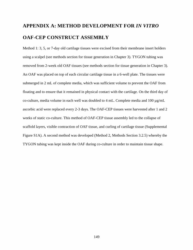
149
APPENDIX A: METHOD DEVELOPMENT FOR IN VITRO
OAF-CEP CONSTRUCT ASSEMBLY
Method 1: 3, 5, or 7-day old cartilage tissues were excised from their membrane insert holders
using a scalpel (see methods section for tissue generation in Chapter 3). TYGON tubing was
removed from 2-week old OAF tissues (see methods section for tissue generation in Chapter 3).
An OAF was placed on top of each circular cartilage tissue in a 6-well plate. The tissues were
submerged in 2 mL of complete media, which was sufficient volume to prevent the OAF from
floating and to ensure that it remained in physical contact with the cartilage. On the third day of
co-culture, media volume in each well was doubled to 4 mL. Complete media and 100 µg/mL
ascorbic acid were replaced every 2-3 days. The OAF-CEP tissues were harvested after 1 and 2
weeks of static co-culture. This method of OAF-CEP tissue assembly led to the collapse of
scaffold layers, visible contraction of OAF tissue, and curling of cartilage tissue (Supplemental
Figure S1A). A second method was developed (Method 2, Methods Section 3.2.5) whereby the
TYGON tubing was kept inside the OAF during co-culture in order to maintain tissue shape.
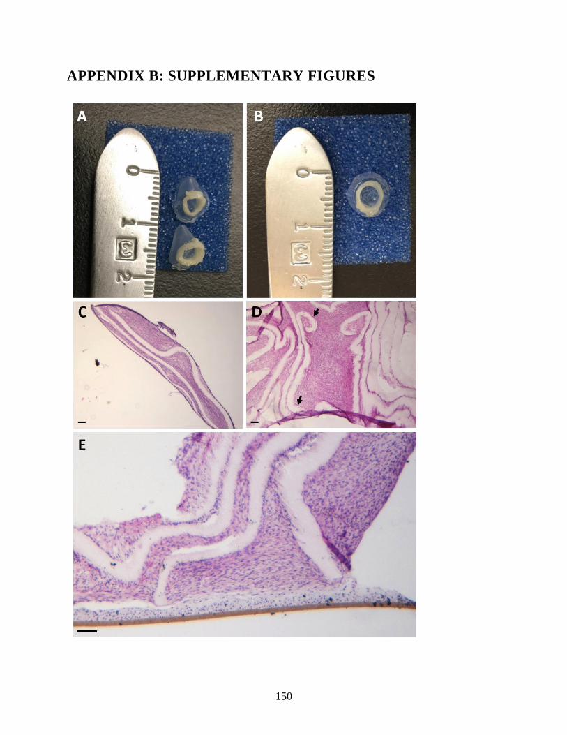
150
APPENDIX B: SUPPLEMENTARY FIGURES
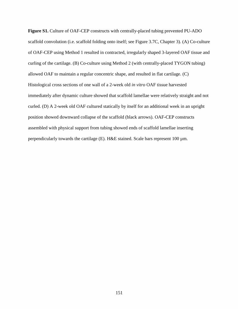
151
Figure S1. Culture of OAF-CEP constructs with centrally-placed tubing prevented PU-ADO
scaffold convolution (i.e. scaffold folding onto itself; see Figure 3.7C, Chapter 3). (A) Co-culture
of OAF-CEP using Method 1 resulted in contracted, irregularly shaped 3-layered OAF tissue and
curling of the cartilage. (B) Co-culture using Method 2 (with centrally-placed TYGON tubing)
allowed OAF to maintain a regular concentric shape, and resulted in flat cartilage. (C)
Histological cross sections of one wall of a 2-week old in vitro OAF tissue harvested
immediately after dynamic culture showed that scaffold lamellae were relatively straight and not
curled. (D) A 2-week old OAF cultured statically by itself for an additional week in an upright
position showed downward collapse of the scaffold (black arrows). OAF-CEP constructs
assembled with physical support from tubing showed ends of scaffold lamellae inserting
perpendicularly towards the cartilage (E). H&E stained. Scale bars represent 100 µm.
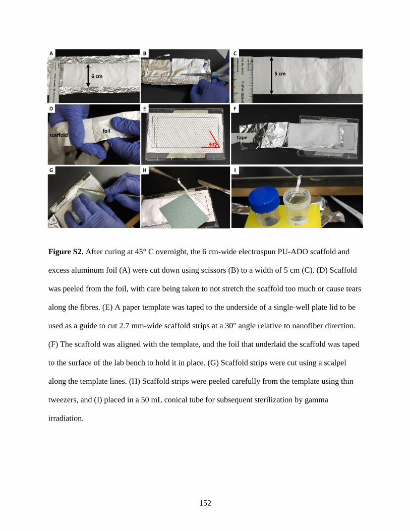
152
Figure S2. After curing at 45° C overnight, the 6 cm-wide electrospun PU-ADO scaffold and
excess aluminum foil (A) were cut down using scissors (B) to a width of 5 cm (C). (D) Scaffold
was peeled from the foil, with care being taken to not stretch the scaffold too much or cause tears
along the fibres. (E) A paper template was taped to the underside of a single-well plate lid to be
used as a guide to cut 2.7 mm-wide scaffold strips at a 30° angle relative to nanofiber direction.
(F) The scaffold was aligned with the template, and the foil that underlaid the scaffold was taped
to the surface of the lab bench to hold it in place. (G) Scaffold strips were cut using a scalpel
along the template lines. (H) Scaffold strips were peeled carefully from the template using thin
tweezers, and (I) placed in a 50 mL conical tube for subsequent sterilization by gamma
irradiation.
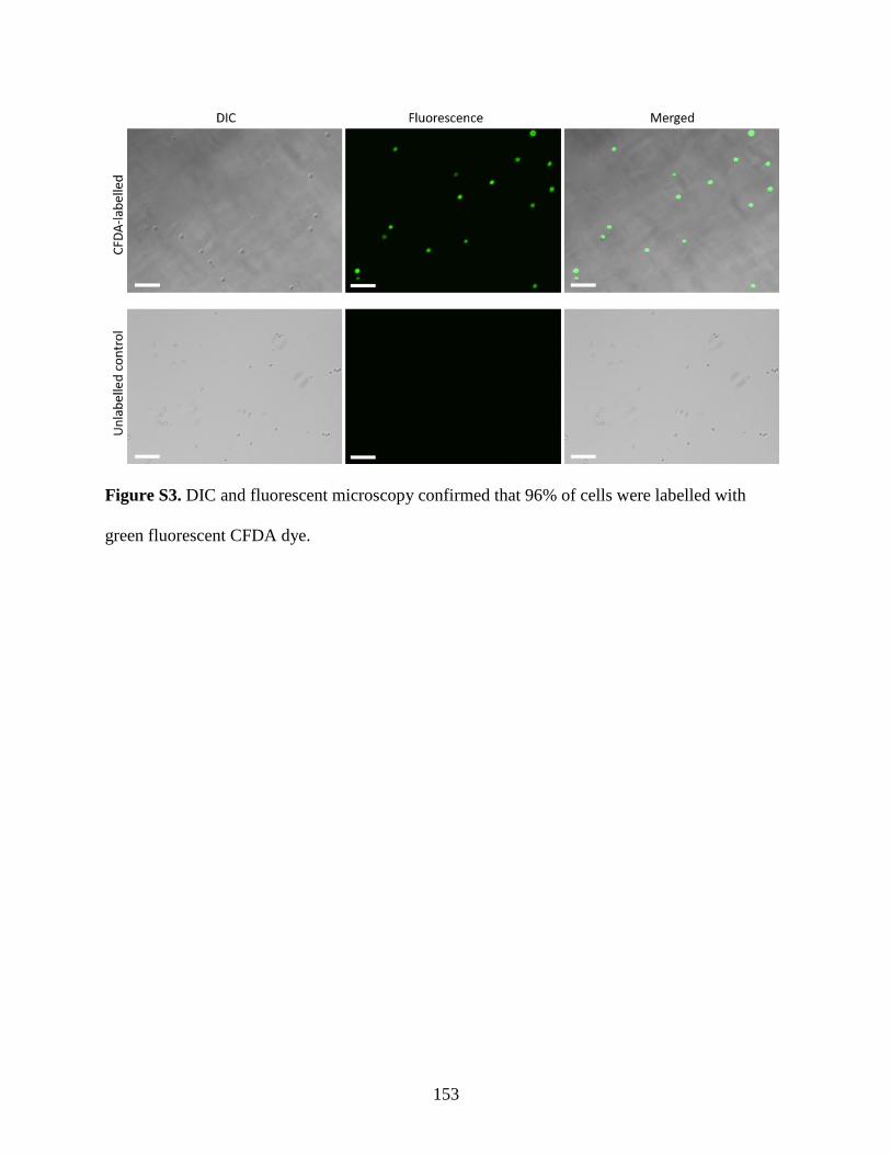
153
Figure S3. DIC and fluorescent microscopy confirmed that 96% of cells were labelled with
green fluorescent CFDA dye.
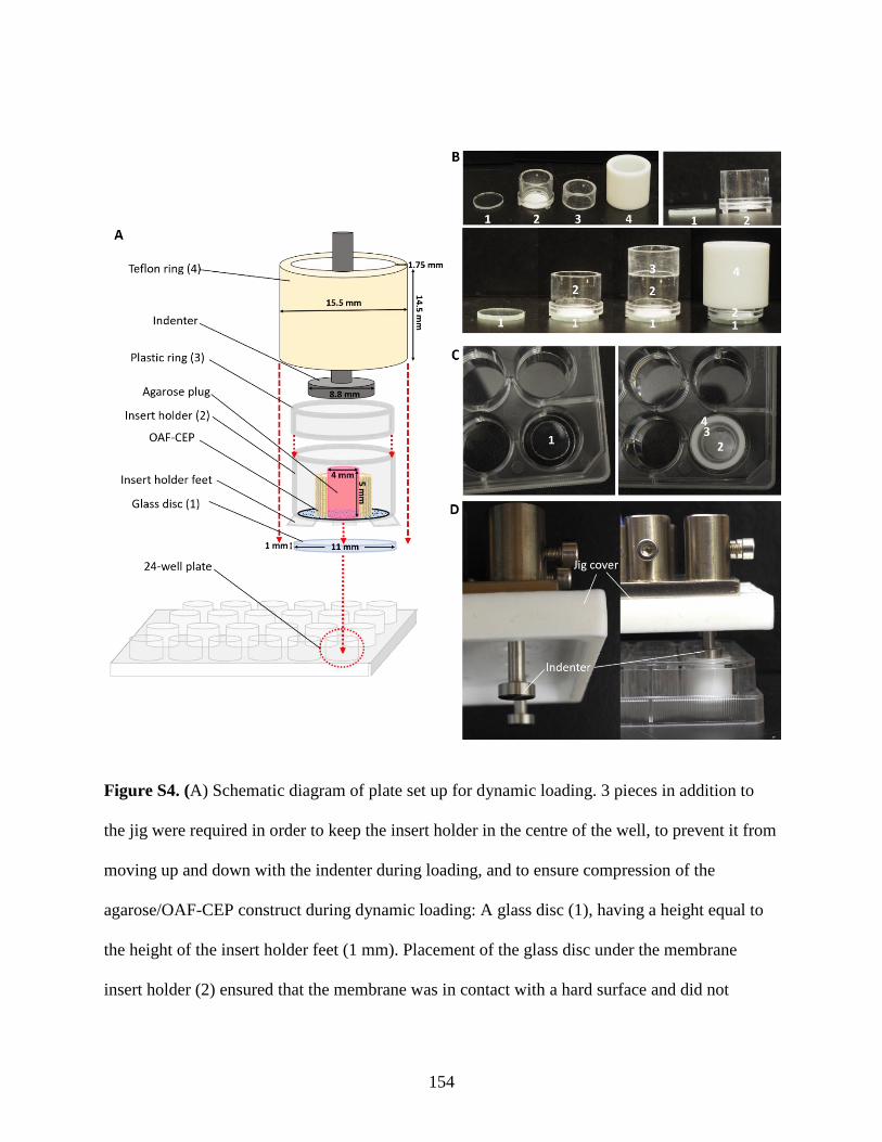
154
Figure S4. (A) Schematic diagram of plate set up for dynamic loading. 3 pieces in addition to
the jig were required in order to keep the insert holder in the centre of the well, to prevent it from
moving up and down with the indenter during loading, and to ensure compression of the
agarose/OAF-CEP construct during dynamic loading: A glass disc (1), having a height equal to
the height of the insert holder feet (1 mm). Placement of the glass disc under the membrane
insert holder (2) ensured that the membrane was in contact with a hard surface and did not

155
stretch downwards during compressive loading; A plastic ring (3), made by cutting off the
bottom portion of an insert holder, provided a continuous surface with the wall of the insert
holder and thus an unobstructed path for the indenter to move through; A Teflon ring (4) with
dimensions to fit exactly around the circumference of the insert holder, and inside of the plate
well. (B) Assembly of all pieces as they appeared inside the 24-well plate. The Teflon ring rested
above the lip of the insert holder and ensured that it was locked down upon placement of the jig
plate cover and during loading. (C) Pieces were assembled inside a standard 24-well plate under
sterile conditions. The glass disc was the first to be placed inside, followed by the insert holder
(containing the OAF-CEP, not shown), the plastic ring, and lastly the Teflon ring. (D) When
assembled, the top surfaces of the outer Teflon ring and inner plastic ring were flush with the top
of the plate. The indenter contacted the surface of the agarose plug during loading.
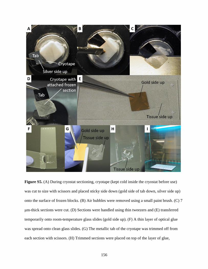
156
Figure S5. (A) During cryostat sectioning, cryotape (kept cold inside the cryostat before use)
was cut to size with scissors and placed sticky side down (gold side of tab down, silver side up)
onto the surface of frozen blocks. (B) Air bubbles were removed using a small paint brush. (C) 7
μm-thick sections were cut. (D) Sections were handled using thin tweezers and (E) transferred
temporarily onto room-temperature glass slides (gold side up). (F) A thin layer of optical glue
was spread onto clean glass slides. (G) The metallic tab of the cryotape was trimmed off from
each section with scissors. (H) Trimmed sections were placed on top of the layer of glue,
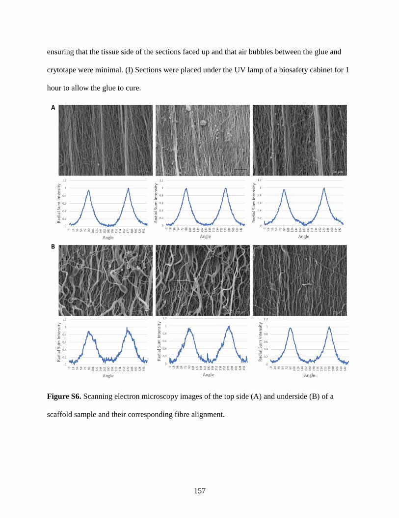
157
ensuring that the tissue side of the sections faced up and that air bubbles between the glue and
crytotape were minimal. (I) Sections were placed under the UV lamp of a biosafety cabinet for 1
hour to allow the glue to cure.
Figure S6. Scanning electron microscopy images of the top side (A) and underside (B) of a
scaffold sample and their corresponding fibre alignment.
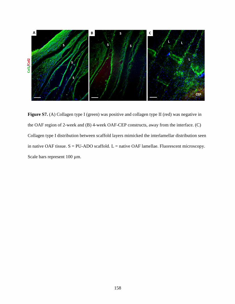
158
Figure S7. (A) Collagen type I (green) was positive and collagen type II (red) was negative in
the OAF region of 2-week and (B) 4-week OAF-CEP constructs, away from the interface. (C)
Collagen type I distribution between scaffold layers mimicked the interlamellar distribution seen
in native OAF tissue. S = PU-ADO scaffold. L = native OAF lamellae. Fluorescent microscopy.
Scale bars represent 100 µm.
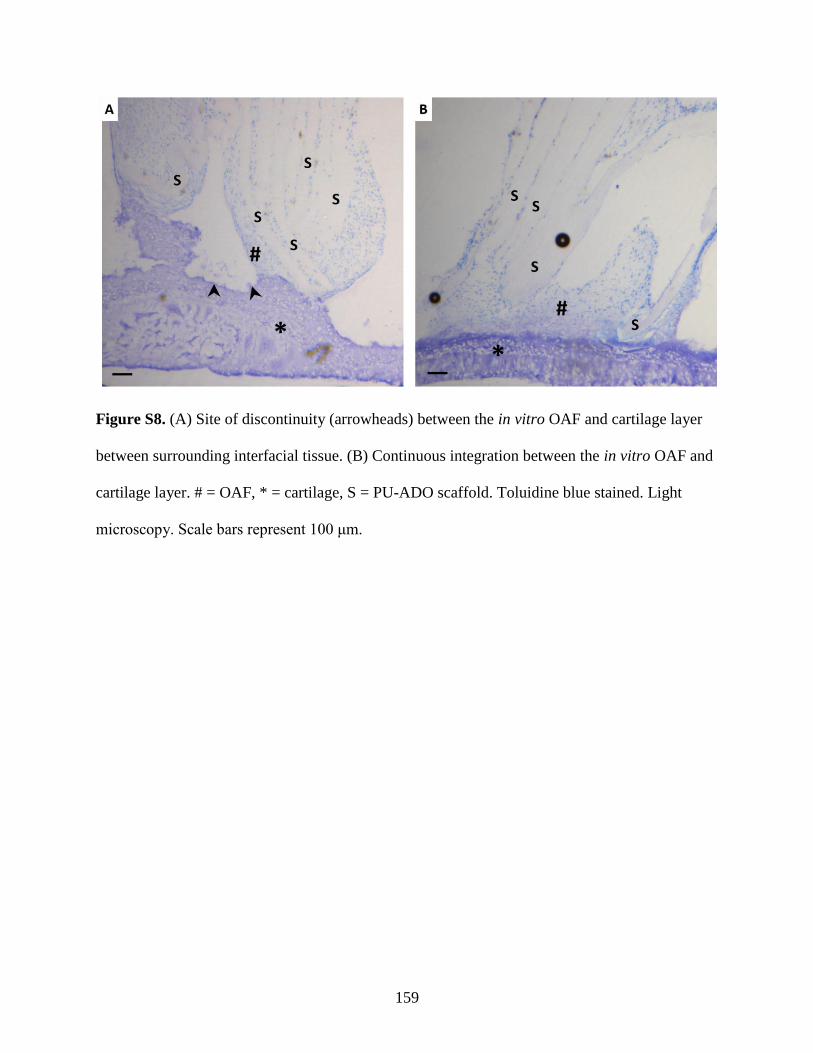
159
Figure S8. (A) Site of discontinuity (arrowheads) between the in vitro OAF and cartilage layer
between surrounding interfacial tissue. (B) Continuous integration between the in vitro OAF and
cartilage layer. # = OAF, * = cartilage, S = PU-ADO scaffold. Toluidine blue stained. Light
microscopy. Scale bars represent 100 μm.
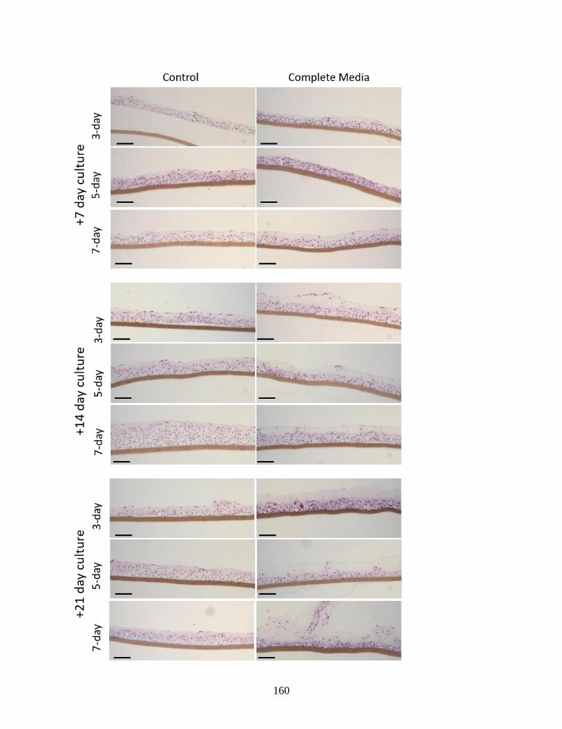
160
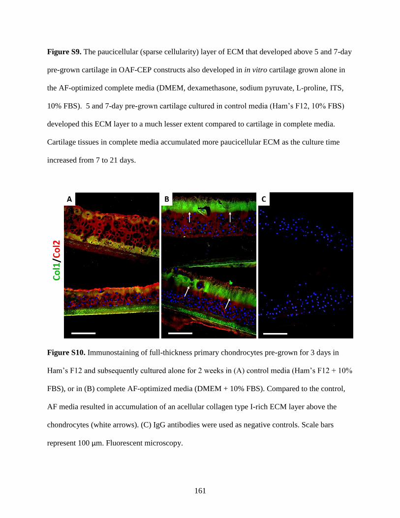
161
Figure S9. The paucicellular (sparse cellularity) layer of ECM that developed above 5 and 7-day
pre-grown cartilage in OAF-CEP constructs also developed in in vitro cartilage grown alone in
the AF-optimized complete media (DMEM, dexamethasone, sodium pyruvate, L-proline, ITS,
10% FBS). 5 and 7-day pre-grown cartilage cultured in control media (Ham’s F12, 10% FBS)
developed this ECM layer to a much lesser extent compared to cartilage in complete media.
Cartilage tissues in complete media accumulated more paucicellular ECM as the culture time
increased from 7 to 21 days.
Figure S10. Immunostaining of full-thickness primary chondrocytes pre-grown for 3 days in
Ham’s F12 and subsequently cultured alone for 2 weeks in (A) control media (Ham’s F12 + 10%
FBS), or in (B) complete AF-optimized media (DMEM + 10% FBS). Compared to the control,
AF media resulted in accumulation of an acellular collagen type I-rich ECM layer above the
chondrocytes (white arrows). (C) IgG antibodies were used as negative controls. Scale bars
represent 100 µm. Fluorescent microscopy.

![Adipose stem cells for intervertebral disc regeneration: current … · 2018. 10. 4. · such as nucleus pulposus cells [35, 36], annulus fibrosus cells [37], cartilagenous chondrocytes](https://img.pdfslide.net/doc/110x75/5fe16d83ab12386dd17eecf1/adipose-stem-cells-for-intervertebral-disc-regeneration-current-2018-10-4.jpg)