Embed Size (px)
Citation preview

DEVELOPMENT OF NON-LINEAR BOND
STRESS-SLIP MODELS FOR REINFORCED
CONCRETE STRUCTURES IN FIRE
By
Jamal Khalaf
A Thesis Submitted in Partial Fulfilment of the Requirements for the
Degree of Doctor of Philosophy
Department of Mechanical, Aerospace and Civil Engineering
College of Engineering, Design and Physical Sciences
Brunel University London
March 2017

i
DECLARATION
The work in this thesis is based upon the research carried out at the Department of
Mechanical, Aerospace and Civil Engineering, Brunel University. Except where
specific references have been made to the work of others, this thesis is the result of
my own work. No part of this thesis has been submitted elsewhere for any other
degree or qualification.
Jamal Khalaf

ii
ACKNOWLEDGEMENT
Firstly, I would like to thank my lord Almighty Allah who helped me to finish this
work.
Thanks to my supervisors Dr Zhaohui Huang and Professor Mizi Fan for their
guidance, support, encouragement and patience throughout the completion of this
research.
Thanks to my family especially my wonderful wife who supports me during my
research, and my sons Harith and Layth and my lovely daughter Dema.
Thanks to my parents and extend my appreciation and gratitude to all my family
members (brothers, sisters and all relatives).
Thanks to my friends for their support and continuous encouragement.
Gratefully acknowledges the financial support of the Ministry of Higher Education
and Scientific Research of Iraqi Government for this PhD project.

iii
PUBLICATIONS
Published Journal Papers
[1] Khalaf J. & Huang Z. (2016). 'Behaviour of the bond between prestressed
strands and concrete under fire conditions'. Construction & Building
Materials, Volume 128, pp. 12-23.
[2] Khalaf J., Huang Z. & Fan M. (2016). 'Analysis of bond-slip between concrete
and steel bar in fire'. Computers and Structures, Volume 162, pp. 1-15.
[3] Khalaf J. & Huang Z. (2017). 'Parametric study on the bond behaviour
between concrete and reinforcement at elevated temperatures ' (under
review).
Published Conference Papers
[1] Khalaf, J. and Huang, Z. (2016) 'Modelling of bond-slip between restressed
strands and concrete at elevated temperatures’, 9th International Conference
on Structures in Fire. Princeton, USA. 1 - 10 June.
[2] Khalaf, J., Huang, Z. and Fan, M. (2015) 'A robust model to predict the
interaction between concrete and steel bar in fire’, First International
Conference on Structural Safety under Fire & Blast. Glasgow, Scotland,
UK. 2-4 September. ASRANet Ltd, pp. 538 - 549.
[3] Khalaf, J., Huang, Z. and Fan, M. (2014) 'Modelling the bond characteristic
between concrete and steel bar in fire' , 8th International Conference on
Structures in Fire. Shanghai, China. 11 - 13 June. Tongji University
Press, pp. 483 - 490.

iv
ABSTRACT
Exposure of concrete structures to high temperatures leads to significant losses in
mechanical and physical properties of concrete and steel reinforcement as well as the
bond characteristics between them. Degradation of bond properties in fire may
significantly influence the load capacity of concrete structures. Therefore the bond
behaviours need to be considered for the structural fire engineering design of
reinforced concrete structures. At present, the information about the material
degradations of concrete and reinforcing steel bars at elevated temperatures are
generally available. However, the research on the response of the bond characteristic
between concrete and reinforcing steel bar at elevated temperatures is still limited.
Due to the lack of robust models for considering the influence of the bond
characteristics between the concrete and steel bar at elevated temperatures, the
majority of the numerical models developed for predicting the behaviour of
reinforced concrete structures in fire was based on the full bond interaction. Hence,
the main purpose of this research is to develop robust numerical models for
predicting the bond-slip between concrete and the reinforcement under fire
conditions. Therefore, the bond-slip between the concrete and reinforcement for
conventional and prestress concrete structures at both ambient and elevated
temperatures has been investigated in this research.
Two models have been developed in this study: the first model is to simulate the
behaviour of bond-slip of deformed steel bars in normal concrete at room
temperature and under fire conditions. The model is established based on a partly
cracked thick-wall cylinder theory and the smeared cracking approach is adopted to
consider the softening behaviour of concrete in tension. The model is able to
consider a number of parameters: such as different concrete properties and covers,
different steel bar diameters and geometries. The proposed model has been
incorporated into the Vulcan program for 3D analysis of reinforced concrete
structures in fire.
The second robust model has been developed to predict the bond stress-slip
relationship between the strand and concrete of prestressed concrete structural
members. In this model, two bond-slip curves have been proposed to represent the
bond-slip characteristics for the three-wire and seven-wire strands. This model

v
considers the variation of concrete properties, strands’ geometries and the type of
strand surface (smooth or indented). The degradation of materials and bond
characteristic at elevated temperatures are also included in the model. The proposed
models have been validated against previous experimental results at both ambient
and elevated temperatures and good agreements have been achieved.
A comprehensive parametric study has been carried out in this research to examine
the influence of bond-slip model on the structural behaviours of normal reinforced
concrete structures. The study investigated the most important factors that can affect
the bond characteristics between concrete and steel reinforcement at elevated
temperatures. These factors are: the concrete cover, spalling of concrete, concrete
compressive and tensile strengths.

vi
LIST OF CONTENTS
DECLARATION ......................................................................................................... i
ACKNOWLEDGEMENT ......................................................................................... ii
PUBLICATIONS ..................................................................................................... iii
ABSTRACT ............................................................................................................... iv
LIST OF CONTENTS .............................................................................................. vi
LIST OF FIGURES ................................................................................................... x
LIST OF TABLES ................................................................................................. xvii
NOTATIONS ........................................................................................................ xviii
Chapter 1 Introduction .............................................................................................. 1
1.1 Structural fire engineering .................................................................................. 1
1.1.1 Fire curves used in structural fire engineering design ................................. 2
1.1.2 Design of structures under fire condition .................................................... 6
1.2 Reinforced concrete structures and the bond between concrete and
reinforcement in fire ......................................................................................... 8
1.3 Research background ....................................................................................... 10
1.4 Research objectives .......................................................................................... 13
1.5 Outline of the thesis .......................................................................................... 15
Chapter 2 Literature review on the bond behaviour under fire conditions ....... 17
2.1 Introduction ...................................................................................................... 17
2.2 Mechanism of bond stress-slip in reinforced concrete ..................................... 18
2.2.1 Bond mechanism for normal reinforced concrete ...................................... 18
2.2.2 Bond mechanism for prestressed concrete ................................................. 21
2.3 Factors affecting on the bond behaviour .......................................................... 25
2.3.1 Effect of concrete on the bond behaviour .................................................. 25
2.3.2 Effect of reinforcement on the bond behaviour ......................................... 26
2.3.3 Effect of the environment on the bond behaviour ..................................... 27
2.4 Design codes related to the bond of reinforced concrete ................................. 28
2.5 Effect of high temperatures on the properties of reinforced concrete structures
........................................................................................................................ 30
vii
2.5.1 The properties of concrete at elevated temperatures ................................. 31
2.5.1.1 Thermal properties of concrete .......................................................... 31
2.5.1.2 Mechanical properties of concrete ..................................................... 33
2.5.2 The properties of reinforcement (steel bar and strand) at elevated
temperatures ............................................................................................ 36
2.5.2.1 Thermal properties of reinforcement ................................................. 36
2.2.2.2 Mechanical properties of reinforcement ............................................ 37
2.5.3 The bond behaviour at elevated temperatures ........................................... 39
2.6 Finite element method ...................................................................................... 47
2.6.1 Modelling the structures under fire conditions .......................................... 47
2.6.2 Introduction to software VULCAN ........................................................... 48
2.7 Conclusion ........................................................................................................ 51
Chapter 3 Analysis of bond-slip between concrete and steel bar in fire ............. 52
3.1 Introduction ...................................................................................................... 52
3.2 Analytical model .............................................................................................. 54
3.2.1 Uncracked stage ......................................................................................... 56
3.2.2 Partly cracked stage ................................................................................... 57
3.2.3 Entirely cracked stage ................................................................................ 61
3.3 Incorporated bond stress–slip model into Vulcan software ............................. 65
3.4 Validations ........................................................................................................ 69
3.4.1 Validations of the bond stress–slip model ................................................. 69
3.4.1.1 Bond stress–slip curve at ambient temperature .................................. 69
3.4.1.2 Bond stress–slip curve at elevated temperatures ................................ 73
3.4.2 Validations of the bond-link element with new developed bond stress–slip
model ....................................................................................................... 78
3.4.2.1 Modelling pull-out test at ambient temperature ................................. 78
3.4.2.2 Modelling simply supported RC beam at ambient temperature......... 81
3.4.2.3 Modelling fire tests of RC beams ...................................................... 83
3.5 Conclusions ...................................................................................................... 89
Chapter 4 Behaviour of the bond between prestressed strands and concrete in
fire .............................................................................................................................. 90

viii
4.1 Introduction ...................................................................................................... 90
4.2 Analytical model .............................................................................................. 92
4.3 Effect of elevated temperatures on the bond strength .................................... 100
4.4 Incorporating the bond stress-slip model into Vulcan software ..................... 102
4.5 Validations ...................................................................................................... 105
4.5.1 Bond stress–slip curve at ambient and elevated temperatures ................. 105
4.5.1.1 Transfer and flexural bonds at ambient temperature........................ 105
4.5.1.2 Bond stress–slip for seven-wire smooth and indented strands at
ambient temperature ..................................................................................... 106
4.5.1.3 Bond stress–slip for three-wire indented and smooth strands at
ambient temperature ..................................................................................... 108
4.5.1.4 Bond stress–slip curves at elevated temperatures ............................ 110
4.5.2 Structural behaviour of prestressed concrete members ........................... 111
4.5.2.1 Modelling of simply supported PC beams at ambient temperature . 111
4.5.2.2 Modelling fire tests of simply supported PC slabs .......................... 115
4.6 Conclusions .................................................................................................... 122
Chapter 5 Parametric study on the bond behaviour at elevated temperatures
.................................................................................................................................. 123
5.1 Introduction .................................................................................................... 123
5.2 Modelling background ................................................................................... 124
5.3 Modelling isolated simply supported reinforced concrete beam .................... 128
5.3.1 Yielding effect of reinforcing steel bars on the bond behaviour ............. 130
5.3.2 The effect of concrete cover on the bond behaviour ............................... 132
5.3.3 The effect of concrete spalling on the behaviour of the beam ................. 140
5.3.4 The effect of concrete strength on the bond ............................................ 145
5.4 Modelling isolated simply supported reinforced concrete slab ...................... 149
5.4.1 The effect of concrete cover on the behaviour of the slab ....................... 150
5.4.2 The effect of concrete strength on the behaviour of the slab ................... 155
5.5 Modelling of reinforced concrete frame structure in fire ............................... 159
5.6 Conclusions .................................................................................................... 163
Chapter 6 Conclusions and recommendations for future works ....................... 165

ix
6.1 Summary of thesis contributions .................................................................... 165
6.1.1 Development of a robust model to simulate the bond stress-slip between
concrete and steel bars at elevated temperatures ................................... 165
6.1.2 Development of a new model to simulate bond stress-slip between the
concrete and prestressed strands in fire ................................................. 166
6.1.3 Parametric study on the bond behaviour at elevated temperatures ........ 166
6.2 Conclusions .................................................................................................... 167
6.3 Recommendations for future studies .............................................................. 168
REFERENCES ....................................................................................................... 170
x
LIST OF FIGURES
Figure 1.1 Phases of real fire development ................................................................. 3
Figure 1.2 ISO 834 (ISO-834, 1975) and ASTM E119 (ASTM E119, 2000) standard
fire curves. ................................................................................................. 3
Figure 1.3 Temperature-time curves used for design of structures under fire
condition .................................................................................................... 4
Figure 2.1 Local bond stress-slip law ....................................................................... 18
Figure 2.2 Wedge action between the steel bar and concrete (Tepfers 1979) .......... 19
Figure 2.3 Bond stress in reinforced concrete for deformed bar ............................... 20
Figure 2.4 Bond stress-slip for plain wire and plain seven-wire strand (CEB-FIP-
Bulletin10, 2000) ..................................................................................... 21
Figure 2.5 Push-in test apparatus .............................................................................. 23
Figure 2.6 Transfer bond length and flexural bond length before and after member
loading ..................................................................................................... 24
Figure 2.7 Expansion of concrete due to corrosion of the embedded steel (Kumar &
Paulo, 2006) ............................................................................................ 28
Figure 2.8 Thermal conductivity of concrete at elevated temperatures .................... 32
Figure 2.9 Specific heat capacity of concrete at elevated temperatures .................... 32
Figure 2.10 Thermal expansion of concrete at elevated temperatures (CEN 2004) . 33
Figure 2.11 Degradation of concrete compressive strength at elevated temperatures
.............................................................................................................. 34
Figure 2.12 Degradation of concrete tensile strength at elevated temperatures........ 35
Figure 2.13 Thermal strains of reinforcing steel bar and strand ............................... 37
Figure 2.14 Degradation of steel bars at elevated temperatures ............................... 38
Figure 2.15 Degradation of strands at elevated temperatures ................................... 39
Figure 2.16 Bond stress-slip relationship of cold deformed steel at elevated
temperatures (Diederichs & Schneider 1981) ....................................... 41
Figure 2.17 Bond stress-slip relationship of prestressing steel at elevated
temperatures (Diederichs & Schneider 1981) ....................................... 41
Figure 2.18 Bond stress-slip relationship of rusted plain round bars at elevated
temperatures (Diederichs & Schneider 1981) ....................................... 42

xi
Figure 2.19 Relative bond strength of various reinforcing bars as a function of
temperatures (Diederichs & Schneider 1981) ....................................... 42
Figure 2.20 Residual bond stress-slip for various temperatures (16 mm steel bar
diameter, 55 mm concrete cover and 3.7 MPa initial stress) (Morley &
Royles 1983) ......................................................................................... 43
Figure 2.21 Residual bond stress-slip curves at various temperatures (16 mm
deformed bar diameter, 55 mm concrete cover with no initial stress)
(Morley 1982) ....................................................................................... 44
Figure 2.22 Residual bond stress-slip for different concrete cover and various
temperatures .......................................................................................... 45
Figure 2.23 Variation of maximum bond stress with temperature for different covers
(16 mm diameter of deformed bar) (Morley & Royles 1983) .............. 45
Figure 2.24 Residual bond strength versus temperature for modified specimens
prepared with different FRC mixtures (Haddad et al. 2008) ................ 46
Figure 2.25 Average bond stress–slip curve defined by CEB-FIP Model Code 1990
.............................................................................................................. 48
Figure 2.26 Reinforced concrete beam: plain concrete, reinforcing steel bar and 3D
bond-link elements (Huang 2010) ........................................................ 50
Figure 3.1 Mechanical action between the steel bar and concrete ............................ 55
Figure 3.2 Partly cracked concrete cylinder .............................................................. 55
Figure 3.3 Uncracked elastic stage ............................................................................ 56
Figure 3.4 (a) Stress-strain curve of concrete in tension (b) Concrete tensile stress-
strain curves at different temperatures .................................................... 58
Figure 3.5 Influence of on the current model at different temperatures: (a) At
500oC, (b) At 300
oC ................................................................................ 60
Figure 3.6 Proposed curves: (a) Bond stress-slip curve (b) Bond stress - Ri curve 63
Figure 3.7 The relationship between the slip and Ri ................................................. 64
Figure 3.8 Bond-link element: (a) 2-D Coordinates (b) 3-D Coordinates ................ 66
Figure 3.9 Comparison of predicted and measured bond stress-slip curves at ambient
temperature .............................................................................................. 73
Figure 3.10 Comparison of predicted and measured bond stress-slip curves at
elevated temperatures ........................................................................... 76

xii
Figure 3.11 Comparison between the predicted and tested stress distributions along
anchored reinforcing steel bar (Viwathanatepa et al. 1979) ................. 80
Figure 3.12 Predicted bond stress distributions corresponding to different end-slips
for test (Viwathanatepa et al. 1979) ...................................................... 80
Figure 3.13 Predicted end-slips vs pull-out force for the test (Viwathanatepa et al.
1979) ..................................................................................................... 81
Figure 3.14 Details of J4 beam tested at ambient temperature (Burns & Siess 1962)
.............................................................................................................. 82
Figure 3.15 Comparison of predicted and measured mid-span deflections of J4 beam
(Burns & Siess 1962) ............................................................................ 82
Figure 3.16 Details of tested beams in fire (Lin et al. 1987)..................................... 83
Figure 3.17 Comparison of predicted and measured temperatures of four main
reinforcing steel layers for Beam 1 (Lin et al. 1987) ............................ 84
Figure 3.18 Comparison of predicted and measured temperatures of four main
reinforcing steel layers for Beam 5 (Lin et al. 1987) ............................ 85
Figure 3.19 Comparison of predicted and measured maximum deflections of Beam1
(ASTM Fire) (Lin et al. 1987) .............................................................. 86
Figure 3.20 Comparison of predicted and measured maximum deflections of Beam3
(ASTM Fire) (Lin et al. 1987) .............................................................. 87
Figure 3.21 Comparison of predicted and measured maximum deflections of Beam5
(SDHI Fire) (Lin et al. 1987) ................................................................ 88
Figure 3.22 Comparison of predicted and measured maximum deflections of Beam6
(SDHI Fire) (Lin et al. 1987) ................................................................ 88
Figure 4.1 Transfer length and flexural length before and after loading ...........Error!
Bookmark not defined.
Figure 4.2 The interaction between the outer wires of the strand and concrete ........ 93
Figure 4.3 Parabolic Mohr Envelope (Curtis 2011) .................................................. 97
Figure 4.4 Bond stress-slip curve: (a) Three-wire strands and indented seven wire
strands, (b) Seven-wire smooth strands................................................... 98
Figure 4.5 Comparison of predicted and tested bond stress–slip curves for the seven-
wire smooth strand at ambient temperature (Vázquez-Herrero et al. 2013)
............................................................................................................... 107

xiii
Figure 4.6 Comparison of predicted and tested load–slip curves for the pull-out
seven-wire indented strands at ambient temperature (Lundgren 2002) 108
Figure 4.7 Comparison of predicted and tested load–slip curves for the three-wire
push-in test at ambient temperature (Gustavson 2004) ......................... 109
Figure 4.8 Comparison of predicted and tested load-slip curves for the three-wire
pull-out test at ambient temperature (Gustavson 2004) ........................ 109
Figure 4.9 Comparison of predicted and tested bond strength degradation with
different concrete compressive strengths at elevated temperatures (Moore
2008): (a) 77.4 MPa; (b) 98.8 MPa. ...................................................... 111
Figure 4.10 Details of tested T-beam Z-1 (Cowen & VanHorn 1967) (all dimensions
in mm) ................................................................................................. 112
Figure 4.11 Comparison of the predicted and tested load versus mid-span deflections
curves for T-beam Z-1 (Cowen & VanHorn 1967) ............................ 113
Figure 4.12 Details of the tested T-girder (T-6-1.5h-A) (Tadros & Morcous 2011)
(all dimensions in mm) ....................................................................... 114
Figure 4.13 Comparison of the predicted and tested load versus mid-span deflections
curves for the tested T-girder (Tadros & Morcous 2011) ................... 114
Figure 4.14 Details of PC Slab TB3 (Bailey & Ellobody 2009) (all dimensions in
mm) ..................................................................................................... 115
Figure 4.15 Comparison between the predicted and tested temperature histories
(Bailey & Ellobody 2009) ................................................................... 116
Figure 4.16 Comparison of predicted and measured mid-span deflections of Slab
TB3 (Bailey & Ellobody 2009) .......................................................... 117
Figure 4.17 Comparison of predicted and tested longitudinal expansion for Slab
TB3 (Bailey & Ellobody 2009) .......................................................... 118
Figure 4.18 Details of PC Slab PSS-1 (Zheng & Hou 2008) .................................. 119
Figure 4.19 Heating curve used in the analysis (Zheng & Hou 2008) .................... 119
Figure 4.20 The predicted and tested temperature histories for Slab PSS-1 (Zheng &
Hou 2008) ........................................................................................... 120
Figure 4.21 Comparison of predicted and measured mid-span deflections of Slab
PSS-1 (Zheng & Hou 2008) ................................................................ 121
Figure 5.1 Whole floor layout of reinforced concrete structure .............................. 125

xiv
Figure 5.2 Division of reinforced concrete building into beam-column, slab,
reinforcement and bond link elements (Huang 2010) ........................... 126
Figure 5.3 Isolated simply supported beam heated by ISO 834 standard fire ........ 128
Figure 5.4 The cross-sectional details of the isolated reinforced concrete beam (all
dimensions in mm) ................................................................................ 128
Figure 5.5 Influence of steel strains on local bond-stress slip relationship (CEB-FIP
2010)...................................................................................................... 131
Figure 5.6 Yielding effect of reinforcing steel bar on the bond behaviour ............. 132
Figure 5.7 Segmentation of the beam cross-section .............................................. 133
Figure 5.8 Temperature histories of the steel bar (Bar 1) for the beam subjected to
ISO 834 standard fire with different thicknesses of concrete cover ..... 134
Figure 5.9 Temperature histories of the steel bar (Bar 2) for the beam subjected to
ISO 834 standard fire with different thicknesses of concrete cover ..... 134
Figure 5.10 Temperature histories of the steel bar (Bar 3) for the beam subjected to
ISO 834 standard fire with different thicknesses of concrete cover ... 135
Figure 5.11 Comparison between full-bond and partial-bond for the concrete cover
of 10 mm ............................................................................................. 136
Figure 5.12 Comparison between full-bond and partial-bond for concrete cover of
20 mm ................................................................................................. 137
Figure 5.13 Comparison between full-bond and partial-bond for concrete cover of
30 mm ................................................................................................. 137
Figure 5.14 Comparison between full-bond and partial-bond for concrete cover of
40 mm ................................................................................................. 138
Figure 5.15 Comparison between full-bond and partial-bond for concrete cover of
50 mm ................................................................................................. 138
Figure 5.16 Influence of concrete cover on the structural behaviour of a simply
supported beam modelled with partial bond ....................................... 140
Figure 5.17 Temperature histories of the reinforcing bars for the beam exposed to
ISO 834 standard fire .......................................................................... 141
Figure 5.18 Influence of concrete spalling on the behaviour of the beam modelled as
full or partial bond .............................................................................. 142
Figure 5.19 Comparison of the behaviour of the beam modelled as full bond or
partial bond (all elements spalled) ...................................................... 143

xv
Figure 5.20 Comparison of the behaviour of the beam modelled as full bond or
partial bond (elements 1&5 spalled) ................................................... 143
Figure 5.21 Comparison of the behaviour of the beam modelled as full bond or
partial bond (elements 2&4 spalled) ................................................... 144
Figure 5.22 Comparison of the behaviour of the beam modelled as full bond or
partial bond (element 3 spalled) .......................................................... 144
Figure 5.23 Time-temperature histories for the reinforcing steel bars of the beam
subjected to IOS 834 standard fire ...................................................... 145
Figure 5.24 Comparison of the behaviour of the beam modelled with full bond and
partial bond using concrete compressive strength of 20 MPa ............ 146
Figure 5.25 Comparison of the behaviour of the beam modelled with full bond and
partial bond using concrete compressive strength of 30 MPa ............ 147
Figure 5.26 Comparison of the behaviour of the beam modelled with full bond and
partial bond using concrete compressive strength of 40 MPa ............ 147
Figure 5.27 Comparison of the behaviour of the beam modelled with full bond and
partial bond using concrete compressive strength of 45 MPa ............ 148
Figure 5.28 Influence of concrete compressive strength on the behaviour of the
beam modelled with full bond ............................................................ 148
Figure 5.29 Influence of concrete compressive strength on the behaviour of the
beam modelled with partial bond ........................................................ 149
Figure 5.30 Details of the isolated slab modelled ................................................... 150
Figure 5.31 The cross-section of the slab modelled ................................................ 150
Figure 5.32 Time-temperature histories of the reinforcing steel bars with different
concrete covers under ISO 834 fire .................................................... 151
Figure 5.33 Comparison of the central deflections of the slab modelled as full bond
or partial bond using concrete cover of 10 mm .................................. 152
Figure 5.34 Comparison of the central deflections of the slab modelled as full bond
or partial bond using concrete cover of 15 mm .................................. 153
Figure 5.35 Comparison of the central deflections of the slab modelled as full bond
or partial bond using concrete cover of 20 mm .................................. 153
Figure 5.36 Comparison of the central deflections of the slab modelled as full bond
or partial bond using concrete cover of 25 mm .................................. 154
Figure 5.37 Comparison of the central deflections of the slab modelled as full bond
or partial bond using concrete cover of 30 mm .................................. 154

xvi
Figure 5.38 Influence of different concrete covers on the central deflections of the
slab modelled as partial bond .............................................................. 155
Figure 5.39 Time-temperature history of the reinforcing steel bars within the slab
exposed to ISO 834 fire ...................................................................... 156
Figure 5.40 Comparison of the central deflections of the slab modelled as full bond
or partial bond using concrete compressive strength of 20MPa ......... 156
Figure 5.41 Comparison of the central deflections of the slab modelled as full bond
or partial bond using concrete compressive strength of 30MPa ......... 157
Figure 5.42 Comparison of the central deflections of the slab modelled as full bond
or partial bond using concrete compressive strength of 40MPa ......... 157
Figure 5.43 Comparison of the central deflections of the slab modelled as full bond
or partial bond using concrete compressive strength of 45MPa ......... 158
Figure 5.44 Influence of different concrete strengths on the central deflections of the
slab modelled as partial bond .............................................................. 158
Figure 5.45 Floor layout of the building with different locations of the fire
compartments ...................................................................................... 160
Figure 5.46 The deflections of the floor slabs at the position a, b and c under whole
floor fire .............................................................................................. 161
Figure 5.47 Comparison of the central deflections of the floor slabs for different fire
compartments ...................................................................................... 161
Figure 5.48 Comparison of the deflections at Position a for compartment fire FC-1
and whole floor fire, together with the central deflection of isolated
simply supported slab. ........................................................................ 162
Figure 5.49 Comparison of the deflections at Position b for compartment fire FC-2
and whole floor fire, together with the central deflection of isolated
simply supported slab. ........................................................................ 162
Figure 5.50 Comparison of the deflections at Position a for compartment fire FC-3
and whole floor fire, together with the central deflection of isolated
simply supported slab. ........................................................................ 163
xvii
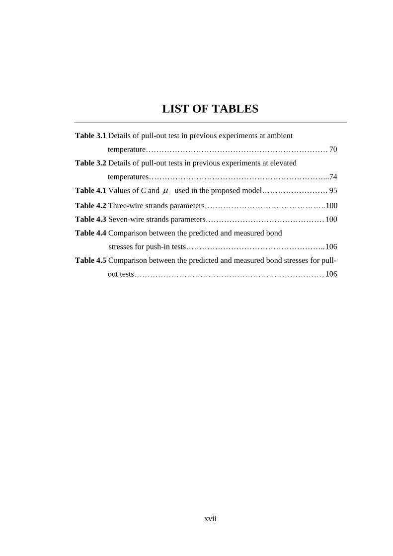
LIST OF TABLES
Table 3.1 Details of pull-out test in previous experiments at ambient
temperature…………………………………………………………… 70
Table 3.2 Details of pull-out tests in previous experiments at elevated
temperatures…………………………………………………………... 74
Table 4.1 Values of C and used in the proposed model……………………. 95
Table 4.2 Three-wire strands parameters……………………………………….100
Table 4.3 Seven-wire strands parameters……………………………………… 100
Table 4.4 Comparison between the predicted and measured bond
stresses for push-in tests…………………………………………….. 106
Table 4.5 Comparison between the predicted and measured bond stresses for pull-
out tests……………………………………………………………… 106

xviii
NOTATIONS
The following symbols are used in this thesis:
u moisture content of concrete weight
r radial stress
Tt , tangential stress at elevated temperatures
i
TP total radial pressure at elevated temperatures
TiP, pressure resistance of the elastic outer zone at elevated temperatures
r radius from the centre of the rebar
sR radius of the steel bar
cR radius of concrete cylinder =sR + the least thickness of concrete cover
iR radius of the uncracked inner face
Tu , smeared strain of concrete at elevated temperatures when tensile stress
equal to zero
0,t smeared tangential strain at the rebar interface
ctf
tensile strength of concrete at ambient temperature
TE ,0 initial elastic modulus of concrete at elevated temperatures
i
T
bond stress at elevated temperatures
effective face angle
Tctf , degradation of the concrete tensile strength at elevated temperatures
C concrete cover
maxS maximum slip at the maximum bond stress point max
i
xTF , bonding force between the concrete and the steel bar
A the contact area between the concrete and the reinforcing steel bar
U perimeter of the steel bar

xix
L length of the steel bar which contributes to the node connected by the
bond element
ΔF nodal force increment vector
Δu nodal displacement increment vector
ik1 tangent stiffness coefficients of the bond connector
bl embedded length of the rebar inside the specimens
bd diameter of the rebar
cV Shear force resistance of the concrete in front of strand ridges
cv shear strength of the shear keys in the concrete mass
shA shear area of the cracked surface
wd diameter of the outer wires
wl length of the wires
ds nominal strand diameter
F force along the length of the wires
C cohesion between the concrete and steel
coefficient of friction
pitch angle of the outer wires
peak shear strength ( cv )
'cf concrete compressive strength
tf concrete tensile strength
n normal stress perpendicular to the strand axes
1P initial tension force on the strand usually equal to 0.75 uf (0.75 ultimate
stress)
2P force after the stress released from the strand
sA nominal area of the strand
sE modulus of elasticity of the strand
v Poisson ratio of the steel equal to 0.3
1s first strain of the strand at 1P
2s second strain of the strand at 2P
c strain of the concrete due to the lateral pressure of strand.

xx
bT maximum bond force in the direction of strand
average bond stress
max maximum bond stress
S slip between strand and concrete.
bA contact area between the strand and concrete
T bond stress at elevated temperatures
Tmax, maximum bond stress at elevated temperatures

1
Chapter 1 Introduction
1.1 Structural fire engineering
Fire can cause massive losses in lives and properties. Hence, the implementation of
fire safety becomes an important part from the building regulation. The Building
Regulation 2000 states that in the Approved Document B, the objectives of ensuring
fire safety in buildings are: maintaining the structural stability for a reasonable
period under fire conditions, restricting the growth and spread of fire, and provision
of safeness, which means evacuation of the occupants and the rescue operation of the
firefighters (ODBM 2000). It is essential for life safety to ensure that the integrity of
the building be maintained during fire. This integrity means that occupants should
have sufficient means and time to escape without being affected by heat or smoke,
and fighting operations have enough time to ensure that the neighbouring buildings
are not affected. The fire resistance of a structure in Eurocodes is expressed by three
failure criteria which are: load bearing capacity by maintaining sufficient strength in
the required duration, insulation by limiting the increase of temperature across
separating elements and integrity to maintain structural integrity against penetration
of hot gases (Lin, 2014). Two types of fire protection methods are used in structures,
active and passive. Active fire protection procedure is a system depends on the
automatic devices such as fire alarms and detecting system or sprinklers. However,
passive fire protection method deals with the structure itself, by ensuring the stability
of the structure during a reasonable time and controlling the spread of fire. This
passive fire protection can be obtained by controlling the building materials and
dimensions, compartments and using fire protection materials (Phan et al. 2010). The
fire starts when the combustible materials get ignited for some reasons. With low
average temperature at the beginning of a fire in a compartment, it is posable to
control the growth of fire by using active fire protection systems like sprinkler
systems and fire extinguishers. However, when the fire is fully developed to ‘post-
flashover’ and the flames spread out, active fire protection systems cannot control
the fire. Therefore, the risk of structural collapse can be great, unless sufficient fire
resistance and fire protection are provided to the structural members during building
design (passive fire protection).

2
Generally, reinforced concrete structure has a good fire resistance. Concrete does not
support combustion, rather it prevents spread a fire to other parts of building and
adjoining structures. Reinforced concrete structure can retain its structural integrity
during a fire, also has good thermal insulation property to keep the unexposed
surface relatively cool (Morley 1982; Kodur 2014).
1.1.1 Fire curves used in structural fire engineering design
Fire resistance of structural elements can be described as the period of time under
standard fire exposer until the failure of the element occurs (Huang 2010). A real fire
depends on the ignition source, sufficient combustible material and oxygen. The
development of a nature fire within a compartment involves three phases as shown in
Figure 1.1. The first phase (pre-flashover) starts when the combustible materials are
ignited. In this phase the average temperature is low and the active fire protection
can control the growth of the fire. However, if the active fire protection systems fail
to contain the fire, the second phase of the nature fire will start at the point of flash-
over (see Figure 1.1). The growth of fire in the second phase depends on the
availability of the fuel and oxygen as well as the ventilation for the small
compartments. After flash over, passive fire protection becomes very important by
designing the structure to prevent the spread of the fire and structural collapse. The
third phase starts after the fire temperature reaches to the maximum, then the
temperature decreases due to the reduction of the combustion rate of the fuel. At this
point, the cool phase will start and the fire curve will drop. The risk of a fire on the
building can be raised during the cooling phase because of the thermal contraction of
the beams can generate large tensile deformation on the connections between beams
and columns, which leads to local failure or even structural collapse.
The test of structural members under fire condition follows the standard codes such
as ISO 834 standard fire (ISO-834 1975), ASTM E119 (ASTM E119 2000) and
Eurocode (CEN 2002). The standard fire curves in ISO 834 and ASTM E119 depend
only on the time of fire exposer, as shown in Figure 1.2, without taking in account
the building characteristics such as compartment size, ventilation condition,
available of combustible material (fire load), and the material of surrounding
surfaces.

3
Figure 1.1 Phases of real fire development
Figure 1.2 ISO 834 (ISO-834, 1975) and ASTM E119 (ASTM E119, 2000) standard fire curves.

4
Figure 1.3 Temperature-time curves used for design of structures under fire condition
Figure 1.3 gives different fire curves based on the type of combustible materials and
the position of the structural member inside or outside of the building.
Standard temperature-time curve is used for design the members located inside a
building and given by Equation (1.1):
18log34520 10 tg (1.1)
where: g is the gas temperature in the fire compartment or furnace (oC), and t is the
time in minutes (ISO-834, 1975).
External fire curve is used for design the members located outside a building and
follows Equation 1.2:
20)313.0687.01(660 .8.3.32.0 tt
g ee (1.2)
Hydrocarbon time-temperature curve is used for design the structure that contains
chemical materials and follows Equation (1.3):

5
20)675.03257.01(1080 .5.2.167.0 tt
g ee (1.3)
For Equations (1.2) and (1.3): g is the gas temperature in the fire compartment or
the furnace (oC), and t is the time in minutes (CEN 2002).
Parametric temperature-time curves:
The parametric time-temperature curve specified in Eurocode EN 1991-1-2 (CEN
2002) provides an estimation of a real fire curve by taking the compartment
characteristics into consideration, such as compartment size, ventilation condition,
available combustible material, fire load, and the material of surrounding surfaces.
This fire curve is valid for fire compartments up to 500 m2 of floor area and height of
4 m without openings in the roof. The gas temperature g inside a compartment
during heating phase can be determined using Equation (1.4):
*** 197.12.0 472.0204.0324.01132520 ttt
g eee (1.4)
where,
tt*
(1.5)
where t is the time in hour.
2
2
)1160/04.0(
/bO (1.6)
where, b is the thermal absorptivity depending on the density , specific heat c
and thermal conductivity of the boundary of an enclosure, which can be calculated
as:
cb (1.7)
And O is the opening factor, expressed as:
2.002.0 OA
hAO
t
eqV (1.8)

6
where, VA is the total area of vertical openings on all walls,
eqh is the weighted
average of window heights on all walls, tA is the total area of enclosure (walls,
celling and floor, including openings). Equation (1.4) approximates the standard
time-temperature curve in case of 1 .
For the cooling phase, the calculation of temperature-time curve is given in EN1991-
1-2 (CEN 2002) as:
2250
25.03250
5.0625
*
max
*
max
*
max
*
max
*
max
**
maxmax
*
max
*
max
*
max
txtt
txttt
txtt
g
(1.9)
where, max is the maximum temperature during the heating phase at *
max
* tt .
0.1x if limmax tt ; or *
maxlim ttx if limmax tt
lim
,
3
max ;102.0
max tO
qt
dt (1.10)
max
*
max tt (1.11)
where dtq , is the design fire load density related to the surface area tA ; limt is the time
for maximum gas temperature in case of a fuel controlled fire; In the case of slow
fire growth rate, min25lim t ; in the case of medium fire growth rate, min20lim t
and in the case of fast fire growth rate, min15lim t (CEN 2002).
Although, parametric time-temperature curve specified in Eurocode EN 1991-1-2
(CEN 2002) provides better prediction to a real fire curve, the standard fire curves
are commonly used for structural fire design and standard fire tests.
1.1.2 Design of structures under fire condition
Codes for fire resistance design differ from country to country around the world, but
all of them have the objectives of protecting the life and property from fire. The main
differences between the fire design and normal temperature design are: the strengths
of materials reduce at elevated temperatures, the cross section areas reduce by

7
charring or spalling, internal forces may be induced by thermal expansion, the
applied load may be changed, the deflections may be important as they may affect
the global stability, and also different failure mechanisms need to be considered
(Phan et al. 2010). The essential point in structural fire design is to ensure that the
real fire resistance of a structure is greater than the design required fire resistance of
the structure. Two methods are used in structural fire design: Prescriptive Fire
Resistance Design and Performance-Based Design for Fire. The first method is a
traditional approach by considering the standard fire curve rather than a real fire. The
structural response in fire is represented by using isolated members tested in the
furnace under standard fire curve (Phan et al. 2010). Hence, the behaviours of real
buildings under real fire conditions cannot be properly considered in this design
method. This is because the standard fire curve cannot accurately represent the real
fires and the performance of isolated structural members is considerably different
with those members within the whole building due to the restraints and interactions
provided by the surrounding structures. Normally this design approach will produce
more conservative fire resistance design. The second design method is the
Performance-Based Design for Fire. In this method designers can take a rational
approach to ensure satisfactory performance of a building in fire by any acceptable
solutions to make economic savings without affecting the fire safety of the building.
For instance, using the parametric fire curve specified in Eurocode (CEN 2002) for
design to take into account different factors that affect on time-temperature curve
and considering the cooling phase of the fire, which may generate thermal
contraction in the beams, resulted lager tensile forces acting on the connections
between beams and columns (Bisby 2012).
Structural fire design in Eurocodes like (CEN 2002) and (CEN 2004) allow
designers to treat the fire as one of the basic design limit states, taking into account
some factors such as, non-uniform heating because of partial protection, realistic
stress–strain properties of structural materials at high temperatures and the level of
loading at fire limit state (Huang 2010). The codes specify minimum required fire
endurance time for building by using acceptable solutions which called “deemed-to-
satisfy solution” to reduce the fire protection cost without undermining the fire safety
of the building. This requirement can be achieved by allowing methods for

8
determining the fire endurance time such as qualification tests and analytical
methods (Phan et al. 2010).
At present, there are three applicable levels of structural fire engineering design, that
are: tabulated data which is used for member analysis by applying standard fire only;
simplified calculation methods which are used for analysis of the parts of the
structure by applying the standard or parametric fire curves; advanced calculation
models for global structural analysis by applying the standard or parametric fire
curves (Law 2016).
1.2 Reinforced concrete structures and the bond between concrete
and reinforcement in fire
Exposure of concrete structures to high temperatures results in significant losses in
mechanical and physical properties of concrete and steel reinforcement as well as the
bond characteristics between them. Degradation of the bond properties in fire may
significantly influence the moment capacity or flexibility of the reinforced concrete
structures. Therefore the bond behaviour should be considered for the structural fire
engineering design of reinforced concrete structures (Pothisiri & Panedpojaman
2013). Right now, information about material degradations such as concrete and
steel reinforcement is generally available at elevated temperatures. However,
investigation about bond behaviour between concrete and rebar at elevated
temperatures is still limited because of complexity, and also the research on the bond
characteristic of prestressed concrete member is very limited.
Failure of concrete in tension is known as a brittle failure; hence concrete members
require an additional support in tension region. This support can be established using
reinforcing steel bars for normal concrete and strands in prestressed concrete
constructions. Concrete and reinforcement need to build a good interaction between
them. This interaction is known as bond stress which must be sufficient to anchor the
rebar. Conventionally, design of reinforced concrete structure is based on the
assumption of strain compatibility as the strain in the concrete and steel bar are the
same at sections under the maximum load. This assumption requires a good bond
between the concrete and rebar and the maximum bond stress can be reasonably
determinated (CEB-FIP-Bulletin10 2000). The quality of the bond controls the

9
needed anchorage length of the rebar. Good bond between the concrete and
reinforcing bars can decrease the construction cost by reducing the anchorage length
of the rebar, and obtaining the full capacity of the concrete members. In fact, bond
between the concrete and steel reinforcing bars is important not only for concrete
and steel to work together as a composite material, but also important to provide the
ductility for the concrete structures. For structural safety, bond gives good
mechanical properties for the structures at local level. Likewise ductility requires a
good bond to resist the large strain of the steel along the anchorage of the rebar when
bending cracks initiated (CEB-FIP-Bulletin10 2000).
From this point of view, it is important to understand the factors that can effect on
the bond performance in order to achieve high bond quality between the concrete
and reinforcement. There are considerable experimental and analytical studies on the
bond characteristics have been conducted. Previous research indicated that many
factors can effect the bond characteristics between the concrete and reinforcement,
such as concrete compressive and tensile strengths; concrete cover; geometric of
reinforcement; bars diameter; transverse reinforcement and direction of casting
(Brown et al. 1993).
Prestressed concrete (PC) members can be constructed utilizing unbonded or bonded
strands. For bonded members, the bond is essential for the success of prestressing
system. Forces are transferred from strands to concrete through end anchors together
with the bond between strand and concrete. Therefore bonded PC beams are more
robust structural members at ambient temperature. However, previous research
indicated that compared to normal reinforcing steel, prestressed steel wires are more
sensitive to elevated temperatures due to the stress level in prestressing wires is very
high (Hou et al. 2015).
Structural fire safety is one of the most important considerations in building
applications as mentioned before. The conventional approach of evaluating fire
resistance through fire tests is expensive, time consuming and limited to study
different parameters. Also, it is difficult to perform a full scale fire test such as whole
building with include different fire compartment within the building. Therefore, an
alternative to fire testing is the use of numerical modelling for evaluating fire
resistance of reinforced concrete structural members. Numerical methodology allows

10
to incorporating various parameters in an efficient and cost-effective way (Kodur &
Shakya 2014). Hence, the experimental data obtained from the tests can be used for
validating of the proposed models before using these models in actual applications.
1.3 Research background
The first attempts for using reinforcement in concrete were during the 19th
century,
in which smooth bars were used to support the concrete in tension. Because of
limited bond stress between the smooth bars and concrete, end hooks were suggested
to increase the anchorage capacity. At the beginning of 20th
century, deformed bars
were introduced to increase the capacity of bond between the concrete and
reinforcement (CEB-FIP-Bulletin10 2000). Many studies since early of the 20th
century about the bond of deformed bars had been done. The results indicated that
using deformed bars with small rib spacing and high ribs can improve the resistance
to slip and increase the ultimate bond strength (Lutz 1970; Goto 1971). Increasing
the roughness of the steel bar improves the bond strength, but splitting resistance of
the concrete surrounding the steel bar limits the bond capacity. Hence, there is no
much point in additional roughness unless extra confinement is provided to the
concrete (CEB-FIP-Bulletin10 2000). The usual way to study the bond between the
concrete and steel bar is pull-out tests. Pull-out test can be done by embedding the
bar inside a prismatic concrete specimen and pull the bar out of the concrete at the
time of test. Short embedded length is usually used in pull-out test to achieve a
uniform bond stress distribution along the embedded bar length (Watstein 1947).
Different theories have been proposed to analyse the state of stress in pull-out
specimens. The theory of elasticity was proposed by Osterman (1951) to calculate
the bond stress distribution between the concrete and steel bars. This theory was
established based on the circumferential stresses and radial stresses surround the
steel bar, which can briefly explained as the transfer load between the rebar and
concrete is achieved by bearing the bar ribs on the concrete. The resultant is a
compressive forces acting on the ribs, which are generated due to the confinement of
the surrounding concrete to the reinforcement. The compressive forces are
decomposed into parallel and perpendicular to the rebar. The reaction forces acting
on the concrete due to the perpendicular components of the compressive forces
acting on the ribs create circumferential tension stresses in the concrete surrounding

11
the steel bar. If these tensile stresses exceed the tensile strength of concrete, splitting
failure occurs due to cracking of concrete (Wang & Liu 2003). Another theory for
analysing the bond stress distribution is the modulus of displacement (K-value). This
theory is built based on the assumption that the bond stress is directly proportional to
the relative displacement between the concrete and reinforcement (Losberg 1964;
Tepfers 1980). An empirical formula was proposed by Lutz (1970) to calculate the
bond strength based on the test results. The effects of concrete and transverse
reinforcement are taken into account in this formula. Parameters like beam width and
number of bars are also considered (Lutz 1970).
Investigation about the bond between strand and concrete in prestress concrete
members was conducted by Welsh and Sozen (1969). The result from this study
indicated that the bond is provided by two mechanisms that is the interlocking and
friction. Parameters such as shrinkage, lateral pressure and concrete settlement were
investigated in this study. Finite elements method had been used to calculate the
stress distribution in the concrete key. Also, the bond as a function of the twist angle
of the strand was investigated in this study (Welsh & Sozen 1968).
During the past decades, numerous models have been developed to calculate bond
stress at ambient temperature. Tepfers (1979) proposed an analytical solution based
on the theory of elasticity (Timoshenko & Goodier 1951) for modelling the bond of
deformed bars. This model was developed based on the propagation of
circumferential cracks of concrete along the rebar which defined as the thick wall
cylinder theory. Two stages were assumed in this theory for modelling the bond: a
lower bond or elastic stage when the concrete surrounding the bar is partly cracked
and upper bond plastic stage when the surrounding concrete is entirely cracked.
Modulus of slip theory was used in this model to analyse the distribution of stresses
along the anchored bar (Tepfers 1979). This analytical solution has been developed
by many researchers to take in consideration many aspects, such as the strain-
softening of concrete in tension to calculate the maximum radial stress and
maximum bond stress (Wang & Liu 2003).
At present, information about the bond between concrete and reinforcement at
ambient temperature are generally available. However, investigation about the bond
characteristic between concrete and reinforcing steel bar at elevated temperatures is

12
still limited. Effect of high temperatures on the bond was studied by Diederichs and
Schneider (1981). The range of temperature was 20-800oC and three different types
of steel reinforcement were used in that study (plain round bars, deformed bars and
strands). The conclusion from the study was that the bond strength is affected by the
test procedure and bar’s shape, in which the smooth bar shows sharper decrease in
bond strength than the deformed bar. Also the study indicated that, degradation of
the bond strength at high temperatures is more than the degradation of concrete
compressive strength. Another study was conducted by Morley & Royles (1983)
about the response of the bond to high temperature. Deformed bars were used in this
test with a range of temperatures 20-750oC. The results indicated that the bond
performance depends upon the concrete strength and the specimens tested during
heating give lower bond strength than others tested after cooling. The effect of
elevated temperature on the bond between deformed rebar and fiber reinforced
concrete was studied by Haddad et al. (2008). In this investigation, the concrete was
mixed with fibres to minimize the damage in the interface between concrete and
reinforcement and this enhances the bond performance at elevated temperatures.
Study of the bond behaviour between concrete and strands for PC structures at
elevated temperatures is more complicated than normal reinforced concrete. A
hollow concrete slab was tested under fire condition by Fellinger et al. (2003) to
study the behaviour of bond for prestressed strands at elevated temperatures. This
study indicated that the bond-slip relation cannot be precisely defined by temperature
alone, whereas this relationship depends on other factors such as thermal expansion
during fire exposer and the support conditions of the member. Experimental study
was carried out by Moore (2008) about the performance of prestressed concrete
bridges under fire condition. Pull-out tests were conducted to study the behaviour of
bond between strands and concrete in prestressed concrete at elevated temperatures.
Two sizes of seven wire strands (12.7 mm & 9.5 mm) and two concrete mix design
(75.8 MPa & 96.5 MPa) with range of temperatures 20-704 oC were used in this
experiment. It can be concluded from this study that the bond strength depends on
some factors such as cracks induced by heating, in which the bond strength was
greater for samples with fewer cracks. Also, the average bond strength was greater
for higher concrete compressive strength and the failure was brittle, while for lower
13
compressive strength ductile failure was observed. Finally, the smaller strand’s
diameter shows better bond strength.
During the past decades, numerous models have been developed to calculate bond
stress at ambient temperature. The majority of these models are empirical and based
on a statistical methodology. Thus, these models are highly dependent on the test
data, which may limit their validity in different situations (Huanzi 2009).
Currently, there are limited numbers of numerical models available for modelling
bond characteristics at elevated temperatures. Huang (2010) adopted the CEB-FIP
bond-slip model at ambient temperature (CEB-FIP Model code 90 1991) and
considered the degradation of bond strength at elevated temperatures by using the
experimental results generated by (Bazant & Kaplan 1996). Huang’s model was the
first development of the bond characteristics in fire. Pothisiri and Panedpojaman
(2013) have proposed a mechanical bond-slip model at elevated temperatures based
on the theory of thick-wall cylinder and smeared crack of concrete in tension.
However, this model was established to calculate the bond-slip based on the
correlation between the experimental slip obtained from previous tests.
Modelling of bond-slip relationship for prestressed concrete at ambient temperature
is limited. These models take in consideration limited parameters and limited cases.
A model was proposed by Benitez & Galvez (2011) to simulate the bond during the
prestressing force release. This model was developed based on thick wall cylinder
theory and considered a single wire (indented bar) without taking in account the
spiral effect of strands. Bolmsvik & Lundgren (2006) used finite element software
DIANA to simulate the bond-slip within the interface between concrete and three-
wire strands only. Different parameters were considered in this study such as
adhesion, friction and mechanical interlocking. Modelling the bond-slip for prestress
structures at elevated temperature was difficult to find in literature.
1.4 Research objectives
As mentioned before, the conventional approach of evaluating fire resistance through
fire tests is expensive, time consuming and there are limitations to study different
parameters. Therefore, an alternative to fire testing is the use of numerical models
for evaluating structural fire resistance of concrete structural members. Numerical
14
models allow researchers to take into account various parameters with an efficient
and cost-effective way.
Due to the lack of robust models for considering the influence of the bond
characteristics between concrete and reinforcement at elevated temperatures, the
majority of the numerical models developed for predicting the behaviour of
reinforced concrete structures in fire were based on the assumption of full bond
interaction (Huang 2010). Hence, the main objectives of this research are to:
Develop a robust numerical model for predicting the bond stress-slip between
concrete and reinforcing ribbed bars for normal reinforced concrete structures
at elevated temperatures. The calculation in this numerical model is based on
the constitutive equations of concrete and geometric properties of the rebar
and concrete cover to find the bond-slip relationship under fire conditions.
Incorporate the bond-slip model proposed above into VULCAN software for
3D analysis of reinforced concrete structures under fire conditions using
bond-link element approach.
Validate the proposed model against previous test results. The validation
consists of two stages: the first stage is to validate bond-slip models for
ribbed bar and strand at both ambient and elevated temperatures; the second
stage is to validate the bond-link element with the developed bond-slip
models, which involves modelling structural members at both ambient and
elevated temperatures.
Develop a robust model for modelling the bond stress-slip between concrete
and strands for prestressed concrete structures under fire conditions. This
model is developed based on the constitutive equations of concrete and
geometric properties of seven-wire and three-wire strands. Also, incorporate
this model into VULCAN software and validate it against pervious test
results.
Conduct a comprehensive parametric study to identify the most important
factors which can effect on the bond characteristics between concrete and
steel reinforcement for reinforced concrete beam and slab at elevated
temperatures.

15
1.5 Outline of the thesis
This PhD thesis consists of six chapters as the following:
Chapter 1 gives an introduction to the structural fire engineering and structural
design under fire conditions; also gives an introduction and background on the topic
of bond stress-slip between concrete and reinforcing steel bars and prestressed
strands for normal reinforced concrete and prestressed concrete structures under fire
conditions. The research background and the main objectives of this PhD project are
presented in this chapter.
Chapter 2 presents a literature review on the bond-slip between concrete and
reinforcement. This chapter starts with definition of the bond stress between concrete
and reinforcement. Then mechanisms of the bond stress-slip for normal and
prestressed reinforced concrete are explained. Also, factors affecting on the bond
characteristic and influence of the bond on the behaviour of concrete structures are
discussed. Codes related to the bond of reinforced concrete are also considered in
this chapter. Then, degradations of the materials and the bond stress at elevated
temperatures are discussed. Finally, a brief introduction about the finite elements
method and VULCAN software for 3D modelling of structures under fire condition
are presented.
Chapter 3 presents the development of the bond-slip model between concrete and
deformed steel bars for normal reinforced concrete under fire condition. This model
is incorporated into VULCAN program using bond-link element approach. Then, the
validation of the model is performed by comparing the predicted results with
experimental data.
Chapter 4 illustrates the development of the bond-slip model between concrete and
strands in prestressed concrete structures at elevated temperatures. The analytical
bond stress-slip model is for modelling the bond with three and seven wire strands at
ambient and elevated temperatures. The developed model is also incorporated into
VULCAN program and validated against the previous test data.
Chapter 5 presents a comprehensive parametric study on the bond between the
concrete and steel bar at elevated temperatures. The study is dedicated to identify the
most important factors that effect on bond behaviour between concrete and

16
reinforcement steel bars for beam and slab members at elevated temperatures. The
parameters include steel bar yielding, concrete cover, concrete spalling, concrete
compressive and tensile strengths.
Chapter 6 gives the conclusions based on the research reported in this PhD thesis
and provides some recommendations for future research works.

17
Chapter 2 Literature review on the bond behaviour
under fire conditions
As mentioned in Chapter 1, the structural fire engineering is one of the most
important subjects, which is directly related into human lives and ownerships.
Therefore, it is important to design the structures which have sufficient fire
resistance in case of fire. Although it is commonly known that reinforced concrete
structures have good fire resistance. However, fire can cause a great reduction in the
strength and stiffness of concrete and reinforcement as well as the bond strength
between them. Hence, this chapter will focus on the bond stress-slip between
concrete and steel rebar for normal concrete structures and the bond stress-slip
between concrete and strands for prestressed concrete structures under fire
conditions.
2.1 Introduction
Reinforced concrete can be considered as a composite material which consists of
concrete and reinforcement. Composite material is a result from combined two or
more different materials to produce a new material which has superior characteristic.
Usually, the components of this material are strengthened each other to avoid the
weakness of each ones. Reinforced concrete consists of concrete matrix and
reinforcement. Plain concrete is strong to resist the compressive stresses but it is
weak in tension, whereas the steel has high tensile strength. Therefore, in reinforced
concrete elements, concrete provides the resistance to the compression load and the
rebar is placed at where tensile load is predicted; and sometimes in compression. The
load is transferred from the concrete to rebar through the bond between them. This
bond may become the weakest part within the concrete member, and it becomes
weaker when the member is exposed to severe environment, such as high
temperatures or fires. Therefore, it is important to understand the behaviour of the
bond between concrete and reinforcement, especially under fire condition, which
may dominate the failure of concrete members.

18
2.2 Mechanism of bond stress-slip in reinforced concrete
Previous researchers indicated that, when the reinforced concrete members are
loaded, the stresses in the interface between concrete and steel bar increase. The
capacity of the interface to transmit stress starts to deteriorate at a particular load
level, and this deterioration becomes worse at elevated temperatures (Pothisiri &
Panedpojaman 2012). The damage at the interface or bond gradually spreads to the
surrounding concretes. The development of this process results in a slip between the
steel and concrete due to the steel strain differs from concrete strain. This strain
difference is the result of relative displacement between concrete and reinforcement.
The mechanism to transfer stresses between concrete and reinforcement can be
represented by adhesion, mechanical interlock, friction and Poisson’s effect. This
mechanism can be classified based on the type of reinforcement.
2.2.1 Bond mechanism for normal reinforced concrete
The interaction between concrete and steel rebar during pull-out process is classified
into different stages based on the level of cracking in the concrete surrounding the
rebar as shown in Figure 2.1 (CEB-FIP-Bulletin10 2000).
Figure 2.1 Local bond stress-slip law
Stage-1: the concrete is in elastic (uncracked) phase and the bond stress b is less
than 1 ( p
1 for plain or smooth bar and D
1 for deformed bar) in this stage. The bond

19
is represented by chemical adhesion between the concrete and steel bar. In this stage,
the concrete surrounding the bar is uncracked and no slip occurs between the
concrete and rebar. The chemical adhesion is accompanied by micro mechanical
interaction that is provided from the rough steel surface. This chemical and
mechanical interaction is broken when the bond stress increases and is followed by
the slip of the bar. Then, a dry friction initiates between the concrete and rebar,
which is strongly affected by the transverse pressures. Bar displacement may occur
because of the bar slip at the interface and the shear deformations. Hence, the slip in
Stage-1 (see Figure 2.1) comes from the localized strains at the interface due to the
shear deformation, not from the relative slip between the concrete and steel bar. In
the case when plain bar is used, the bond stress-slip curve is as shown in curve 4a.
Stage-4a is provided by friction, bar roughness, effect of transvers pressure and
concrete shrinkage until the interface deteriorating due to slippage of the bar.
Stage-2 starts when bond stress for deformed bar D
b 1 as shown in Figure 2.1.
Great bearing stresses in the concrete are induced by the bar ribs after breaking the
adhesion. The transverse micro-cracks start to appear at the tips of the bar ribs. It is
indicated that the steel bars with large ribs and small ribs spacing have a greater
anchorage capacity. Also, the rib face should be inclined at 45o or more to the bar
axis in order to achieve crushing of the concrete in front of the ribs during the pull-
out of the bar (Hertz 1982).
Figure 2.2 Wedge action between the steel bar and concrete (Tepfers 1979)

20
Stage-3 is the most important and complicated phase. This stage begins when the
transverse cracks radially spread from the interface through the concrete cover due to
wedging action and crashing the concrete in front of the bar ribs (see Figure 2.2 and
2.3). The transfer of the load between the reinforced bar and concrete is achieved by
bearing of the ribs on the concrete interface. The resultant force acting on the rib is a
compressive force generated due to the restraint of the surrounding concrete. As
shown in Figure 2.3, the compressive forces *P acting on the ribs, resulted from the
pull out load, are decomposed into two directions, parallel and perpendicular to
longitudinal axis of the reinforcing bar l and r respectively. The reaction forces
acting on the concrete due to the perpendicular components of *P , create
circumferential tension stresses c in the concretes surrounding the steel bar. If
these tensile stresses exceed the tensile strength of concrete, splitting failure occurs
(see Stage-4b and3 in Figure 2.1) (Tepfers 1979; CEB-FIP-Bulletin10 2000; Wang
& Liu 2003).
Figure 2.3 Bond stress in reinforced concrete for deformed bar
In the case of high confinement is provided from the concrete cover and the
transverse reinforcement, a pull-out failure of bond occurs instead of splitting failure
(Stage-4c in Figure 2.1). The type of bond failure due to the level of confinement
effects may be defined as a ‘splitting-induced pull-out failure’ when the level of

21
confinement is moderate, or ‘pull-out failure’ if the level of confinement is high. In
the pull-out failure the transfer of force mechanism changes from rib bearing to
friction after crushing all concrete in front of the ribs. Finally, the bond will finish
when the interface is flattened because of the wear and compaction. All these stages
represent the local behaviour of the bond. However, the global behaviour of the bond
is a result from the superimposition of the various stages (CEB-FIP-Bulletin10
2000).
2.2.2 Bond mechanism for prestressed concrete
Mechanism of the bond in prestressed concrete (PC) member depends on type of the
prestress reinforcement (one wire or strand). Figure 2.4 illustrates the relation
between the bond stress verses slip for the plain wire and strand. As shown from the
figure the bond strength in strand dose not drop after a small slip and that attributes
to the mechanical interlocking.
Figure 2.4 Bond stress-slip for plain wire and plain seven-wire strand (CEB-FIP-Bulletin10, 2000)
One high tension steel wire can be found as a plain or indented wire. For the plain
wire, the bond mechanism is attributed to the adhesion and friction as well as the
effect of Poisson’s ratio. Adhesion contributes by a minor value of the bond, as this

22
adhesion bond will disappear after a very small slip between the concrete and wire.
Then, the pull-out force is transferred by friction. The friction between the steel and
concrete is affected by many factors such as roughness of the interface and redial
compressive stress (CEB-FIP-Bulletin10 2000). The radial stresses are generated as
a result from shorten of concrete and Poisson’s effect, in which the diameter of the
wire will increase due to Poisson’s effect after releasing the pretension force from
the wire. This expansion in the diameter improves the bond by increasing the
confinement. When the stress in steel increases as a result from the member loading,
the Poisson’s effect will decrease because of the reduction of wire diameter. As a
consequence, the bond resistance decreases sharply until losing the bond stress when
large slip occurs.
For the indented wire, some researchers proposed the mechanical interlocking
between the indentations and concrete to work like the ribs in deformed bars. The
theory of thick wall cylinder is adopted by (Benitez & Galvez 2011) to model the
bond between the indented wire and concrete. This model can be used just in case of
splitting failure of bond when thin concrete cover is used. The bond strength in this
model is strongly affected by the shape and the size of indentation.
Strand is known as a group of wires (two, three or seven wires) are twisted to form
the prestressing strand. Generally, the bond between the concrete and strand in PC
member is categorized as transfer bond and flexural bond (Abrishami & Mitchell
1993). During PC manufacture, strands are initially pretensioned by using jacks at
the ends abutments. The concrete is cast and cured then the strands are cut. Initial
tensioning of the strands causes a reduction of the strands diameter due to Poisson’s
effect. After concrete reaches sufficient strength, the strands are released from the
abutments, and the stresses in the strands at the free ends of the member return to
zero. With this reduction of the strands stresses, the diameter of the strand expands
along the transfer length and wedging action caused by lateral expansion (called
Hoyer effect) results in improving the bond performance over the transfer bond
length (Abrishami & Mitchell 1993). From the literature, to determine the bond
stress for the flexural bond length, normal pull-out tests have been conducted by cast
the concrete surrounding the strand then the strand is pulled from the concrete with
measuring the pull-out force versus the slip. However, the bond for the transfer bond

23
length can be obtained by using push-in test. This test can be carried out by applying
initial prestress on the strand between points A and B, and then casting the concrete
at point C until the time of test, then releasing the stress from the strand at point A
gradually toward point B with recording of the stress released versus the slip. This
process is illustrated in Figure 2.5 (Abrishami & Mitchell 1993; CEB-FIP-Bulletin10
2000).
Figure 2.5 Push-in test apparatus
Figure 2.6 explains the different between the transfer bond length and flexural bond
length before and after member loading. Figure 2.6(b) shows the variation of stresses
in the pretensioned strand along the beam after release the prestress from the strand
and before loading. Figure 2.6(c) shows the variation of stresses in the strand for the
same beam that is subjected to external load. The transfer bond length tl , as shown
in Figure 2.6(b) is the distance from the end of the concrete where the strand stress is
zero to the point where the strand stress reaches to the maximum level for an
unloaded beam. The flexural bond length fl starts from the end of the transfer bond
length to the point in which the ultimate stress can be developed after loading (see
Figure 2.6(c)).

24
Figure 2.6 Transfer bond length and flexural bond length before and after member loading
The mechanism that contributes to the bond between prestressed strand and
surrounding concrete is known as chemical adhesion, friction and mechanical
interlocking between the outer wires of the strand and concrete. Adhesion bond has a
small effect on the total bond which can be lost in the early stage after little slippage
in the strand. Then, the main dominant factors to the bond mechanism are the dry
friction and mechanical interlocking (Marti-Vargas et al. 2013). As mentioned
before, concrete shortening and Poisson’s effect provide the confinement to the
reinforcement, which contributes in increasing the friction bond strength. However, a
reduction in the diameter of the strand can occurs after member loading, resulted in

25
decreasing the effect of friction due to confinement reduction. Hence, the mechanical
interlocking becomes the main provider to the bond strength.
When concrete is casted around the strands in prestressed concrete members, the
concrete forms an envelope or sleeve surrounding the strand. The hardened concrete
mimics the shape of strand. When the strand is pulled through the concrete, the
movement is resisted by the concrete keys acting on the outside wires of the strand.
The mechanical interlocking is the largest contributor to the bond, especially in
cracked regions. When the cracks are formed in the concrete surrounding the strand,
the slip of the strand occurs for some small finite distance on either side of the crack
to preserve the compatibility of the strand (Russel & Burns 1993). When the slip
occurs, the mechanical interlocking is activated by the interlocking reaction of the
outside wires of the strand with the concrete envelope. The slip is caused mainly by
crushing of the concrete in front of the strand’s ridges. The high pressure on the
concrete in front of the ridges causes tensile stresses in the concrete surrounding the
strand, which in turn create internal inclined cracks. These inclined cracks are
initiated at relatively low bond stresses at the point of contact between the strand and
concrete. Growing of the stress in the strand leads to increasing the slip, and the
concrete in front of the ridges will be crashed. More slip can occur due to more local
crushing takes place. Thereafter, shear cracks will initiate within the concrete keys
between the strand ridges. After reaching the maximum bond resistance, these
concrete keys are sheared off and deterioration of the bond will start (Russel &
Burns 1993; Choi et al. 2010).
2.3 Factors affecting on the bond behaviour
Bond behaviours of normal and prestressed concrete structures are affected by
different factors and parameters. Type of concrete and reinforcement in addition to
the external environment and affect the state of stresses are the main factors that
influence on the bond behaviour.
2.3.1 Effect of concrete on the bond behaviour
The quality of concrete is one of the most important factors affecting the bond
characteristics. As mentioned before, the bond action is a result from the pressure
that formed in front of the bar ribs and the shear forces of the concrete in the

26
interface between the concrete and rebar. Therefore, the capacity of bond strength is
directly affected by the concrete compressive and tensile strengths. Also, the cast
direction of the concrete with respect to bar orientation is another factor which
effects on the bond performance. The bond behaves better when the bars placed
horizontally close to the bottom of the concrete member, and for the vertical bars the
cast of the concrete in the direction against bar loading gives better bond strength
(CEB-FIP-Bulletin10 2000). Concrete cover plays a significant role in bond
performance. Increasing the concrete cover provides the confinement to the rebar
and increases the level of the circumference stresses within the concrete cylinder
surrounding the steel bar. The state of these stresses can weaken the bond strength
and can change the bond failure from pull-out to splitting failure.
2.3.2 Effect of reinforcement on the bond behaviour
The geometry of reinforcing bar can control the behaviour of bond. In case of
deformed bar is used in reinforced concrete structures, the bond is strongly affected
by the rib height h, rib spacing RS and the bar’s diameter bd . The bond index Rf can
be calculated based on these factors as:
Rb
RR
Sd
Af
.. (2.1)
where: RA is the area of the two side of the projection rib. Generally, the bond index
is in the range of 0.05-0.1, which can give a good indication about the bond
performance (CEB-FIP-Bulletin10 2000).
Yielding the steel in the plastic range has a severe effect on the bond strength
(similar to the effect of splitting). A reduction in the steel diameter can occur due to
steel yielding. This bar contraction leads to a great reduction in the friction between
the concrete and rebar, and also affect the geometry of the bar ribs (bond index)
(CEB-FIP-Bulletin10 2000).
For prestressed concrete members indented strands perform better than smooth
strands in terms of bond, but it could be dangerous when thin prestressed members
are used due to splitting failure. Typically, increasing the outer wires diameters and
reducing the pitch angle of them result in higher bond strength. Poisson’s ratio
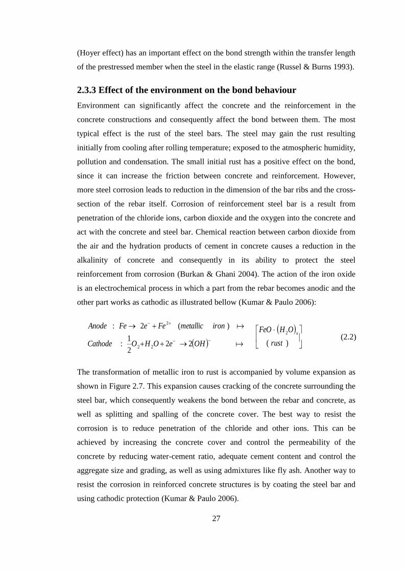
27
(Hoyer effect) has an important effect on the bond strength within the transfer length
of the prestressed member when the steel in the elastic range (Russel & Burns 1993).
2.3.3 Effect of the environment on the bond behaviour
Environment can significantly affect the concrete and the reinforcement in the
concrete constructions and consequently affect the bond between them. The most
typical effect is the rust of the steel bars. The steel may gain the rust resulting
initially from cooling after rolling temperature; exposed to the atmospheric humidity,
pollution and condensation. The small initial rust has a positive effect on the bond,
since it can increase the friction between concrete and reinforcement. However,
more steel corrosion leads to reduction in the dimension of the bar ribs and the cross-
section of the rebar itself. Corrosion of reinforcement steel bar is a result from
penetration of the chloride ions, carbon dioxide and the oxygen into the concrete and
act with the concrete and steel bar. Chemical reaction between carbon dioxide from
the air and the hydration products of cement in concrete causes a reduction in the
alkalinity of concrete and consequently in its ability to protect the steel
reinforcement from corrosion (Burkan & Ghani 2004). The action of the iron oxide
is an electrochemical process in which a part from the rebar becomes anodic and the
other part works as cathodic as illustrated bellow (Kumar & Paulo 2006):
OHeOHOCathode
ironmetallicFeeFeAnode
222
1:
)(2:
22
2
)(
2
rust
OHFeOx
(2.2)
The transformation of metallic iron to rust is accompanied by volume expansion as
shown in Figure 2.7. This expansion causes cracking of the concrete surrounding the
steel bar, which consequently weakens the bond between the rebar and concrete, as
well as splitting and spalling of the concrete cover. The best way to resist the
corrosion is to reduce penetration of the chloride and other ions. This can be
achieved by increasing the concrete cover and control the permeability of the
concrete by reducing water-cement ratio, adequate cement content and control the
aggregate size and grading, as well as using admixtures like fly ash. Another way to
resist the corrosion in reinforced concrete structures is by coating the steel bar and
using cathodic protection (Kumar & Paulo 2006).

28
Figure 2.7 Expansion of concrete due to corrosion of the embedded steel (Kumar & Paulo, 2006)
Another environmental factor effect on the bond is the low and high temperature.
Generally, low temperature has a favourable effect on concrete by increasing the
compressive strength, the tensile strength and the modulus of elasticity of the
concrete (CEB-FIP 2010). Hence, the bond strength for reinforced concrete members
at low temperature is usually higher than that at room temperature, and the bond
failure can be shifted from splitting to shear failure at -40oC (CEB-FIP-Bulletin10
2000). The effect of high temperatures on the bond is intensively explained in
Section 2.5.3.
2.4 Design codes related to the bond of reinforced concrete
The development of economical and reliable concrete structure system depends on
the improvement of design codes. The codes are usually developed based on the
knowledge of designers, researchers, contractors as well as the codes’ written bodies
themselves. The rules in the code have to be general and widely applicable in
different scenarios. Also, the rules should be simple and easy to apply and the most
important thing is to be robust and conservative. Generally, for reinforced concrete
structures, strain compatibility between concrete and reinforcement is the main

29
factor that should be maintained, thus the components act as a composite structure.
Design codes such us European standard (EN), American Concrete Institute (ACI)
and fib (CEB-FIP) follow the research community by taking the information in form
of test data, formulas and recommendation. Then rules are set for designers for
structural design (CEB-FIP-Bulletin10 2000). Bond performance is affected by a lot
of parameters such as material properties, concrete confinement and bar spacing. The
majority of bond formulations in the current design codes are empirical based on a
statistical methodology. Thus, these formulations are highly dependent on the test
data, which may limit their validity in the different situations (Huanzi 2009).
Therefore, the newer form of analysis involves complicated examination using
nonlinear finite element calculations to give more details about the bond phenomena
(Phan et al. 2010). Lots of national codes are to represent a particular national view
and philosophy, for example American Concrete Institute (ACI), Germany Industry
Norm (DIN), British Standards (BS) and Japanese Society of Civil Engineering
(JSCE). However, few codes are considered as multinational codes such as the
Eurocodes (EN) and CEB-FIP Code. These multinational codes have been developed
based on the collective experience of researchers and designers all over the world
(CEB-FIP-Bulletin10 2000).
It is important to know the way that codes explain the bond. Designing for bond in
codes is explained based on the traditional capacity design approach. Hence, actual
bond stress is not necessarily to be calculated; rather the anchorage length should be
computed to the point of bar yielding, which can be done by giving the materials and
the geometric properties of the anchorage. Formulations of bond stress in codes are
empirical relationship based on the test data of bond strength. These bond formulas
in the design codes are found to be simple and can be used for the hand calculation
of anchorage length. However for more complicated situations, such as earthquake
or blast, a computer program is needed to perform the analysis by using finite
element methods.
The accurate evaluation of the performance of reinforced concrete structures depends
on the ability of the designer to model the constituent materials as well as the bond
between the concrete and steel bars (Phan et al. 2010). The most popular bond-slip
model is the one in the CEB-FIP Model Code 90 (CEB-FIP Model code 90 1991).

30
For the bond strength it is generally supposed that increasing the bond strength result
in improving the performance of the reinforced concrete structure itself. However,
this opinion is not always supported by the experimental data. This is because that
the failure mode of the bond can change from pull-out to splitting failure, which
decreases the ductility of the member. In such case, increasing the capacity of
splitting bond in the member can be done by providing additional confinement to the
bar, which can be achieved by providing extra transvers steel. From this point of
view, extra cost to increase the bond strength is not needed and the performance of
the structure still acceptable even there is a small slippage in the bar (CEB-FIP-
Bulletin10 2000).
2.5 Effect of high temperatures on the properties of reinforced
concrete structures
The behaviour of reinforced concrete structural element exposed to fire depends on
the thermal and mechanical properties of its component (concrete, steel and bond
between them). Previous researches indicated that concrete structures begin losing
strength rabidly when temperature reaches higher than 300oC. Typically, when
temperature exceeds 1000 oC the concrete compressive strength reduces by about
90% and the modulus of elasticity reduces by 70% compared to the values at
ambient temperature. The strength of reinforcing steel bars is intensively decreased
after temperature of 300 oC. At temperature about 600
oC, the strength of
reinforcement is only about 35-45% of the corresponding strength at ambient
temperature. Also the reduction of the bond strength between the concrete and steel
bar is about 30-50% of its ambient temperature strength at temperature of 400oC-500
oC. All these reductions in material strengths cause degradation in the stiffness of
reinforced concrete structural member (Morley 1982; Griffin & Beavis 1992; CEN
2004a; Elghazouli et al. 2009; Rivera et al. 2016).
On the other hand, at elevated temperatures cracking and spalling of concrete can
also take place due to different rate of longitudinal thermal expansion of steel and
concrete. The spalling of concrete cover causes buckling of reinforcement due to
directly exposed to fire. Also, concrete member cannot fulfil its structural
requirements if the bond between concrete and reinforcement is lost because of the

31
high temperatures. As a result, the concrete element loses its load carrying capacity
and failure can take place. However, when the whole structure is considered under
fire conditions two notes should be taken in consideration for design: the first note is
the capacity of the concrete members will change due to the redistribution of forces
and bending moments within a continuous structure, and the second note is the
restraint of the member by the surrounding cooling structure may give an increase in
fire resistance (Morley 1982). Therefore it is important to study the effect of elevated
temperatures on the thermal and mechanical properties of concrete and
reinforcement as well as the bond between them.
2.5.1 The properties of concrete at elevated temperatures
2.5.1.1 Thermal properties of concrete
Thermal properties of concrete such as thermal conductivity cK and specific heat
cpC , are strongly affected at elevated temperatures. Thermal conductivity of concrete
is influenced by many factors such as moisture and mix characteristics of concrete.
Generally, thermal conductivity of air is much lower than thermal conductivity of
water. Therefore the loss of moisture, when concrete is exposed to high temperature,
leads to replace the free water with air, which results in lowering the thermal
conductivity of concrete. Normally, thermal conductivity of aggregate is higher than
that of cement past. Hence aggregate is the responsible factor for the considerable
variation of concrete thermal conductivity. Previous researches indicated that
thermal conductivity of aggregate decreases by increasing temperature
(NUREG/CR-7031 2010). Specific heat cpC , of concrete is increased when
temperature is increased. Figure 2.8 and 2.9 illustrate the thermal conductivity and
specific heat of concrete at elevated temperatures, respectively (CEN 2004; Gao et
al. 2013).
Thermal expansion of concrete represents the change of concrete volume due to the
change of temperature. The thermal expansion of concrete has an effect on the
structural movement and thermal stresses, which can lead to cracking and spalling of
the concrete at elevated temperatures (NUREG/CR-7031 2010). The thermal
expansion of concrete increases with temperature, as shown in Figure 2.10 (CEN

32
2004). Moreover, due to drying, dehydration, disintegration and thermal expansion
of concrete at elevated temperatures, concrete experiences a reduction in weight and
density (Huang 1995).
Figure 2.8 Thermal conductivity of concrete at elevated temperatures (CEN, 2004a)
Figure 2.9 Specific heat capacity of concrete at elevated temperatures (CEN, 2004a)

33
Figure 2.10 Thermal expansion of concrete at elevated temperatures (CEN 2004a)
2.5.1.2 Mechanical properties of concrete
The mechanical properties of concrete, such as strength and modulus of elasticity,
are significantly affected by high temperature. Compressive strength of concrete is
considerably reduced at elevated temperatures. This reduction is attributed to the
degradation of the calcium silicate hydrate (C-S-H) because of water losing and
dehydration of other components such as calcium hydroxide ( 2OHCa ) and
ettringite ( OHOHSOAlCa 2123426 26. ). Also different thermal expansion of
aggregate and cement past is another important factor to initiate internal thermal
stresses and form micro-cracks which can crumble the concrete (Arioz 2007).
Adding water to cement is necessary for hydration process, but adding extra water to
increase the workability will result in increasing the water porosity (Rivera et al.
2016). Exposing the concrete to high temperature leads to generate a water vapour
pressure inside the pores. This will result in concrete cracking, damaging concrete
elements and explosive spalling of concrete, especially with high density and low
porosity of the cement past.

34
The properties of concrete can be improved for resisting high temperature by using
amelioration materials, such as fly ash and slag. The use of these materials can
reduce the amount of chemical and physical sorbet water which can limit the interior
stresses and spalling at elevated temperatures (Rivera et al. 2016).
As mentioned above, concrete can be decomposed due to the thermal incompatibility
between aggregate and cement paste at high temperatures. Hence, the performance
of concrete at elevated temperatures is considerably affected by the aggregate type
due to the variation of thermal conductivity and thermal expansion of aggregates.
The thermal conductivity of concrete affects the rate of heat transfer between the
exposed surface and cool surface whereas the thermal expansion of concrete affects
the cracking and spalling of concrete. Calcareous aggregates have more favourable
thermal properties than siliceous aggregates due to less thermal expansion and
thermal conductivity (Morley 1982). When concrete is exposed to high temperatures
cement paste shrinks while the aggregate expands. Therefore, cracking of concrete
can occurs due to the different volume changes between aggregate and cement paste.
Figure 2.11 Degradation of concrete compressive strength at elevated temperatures (CEN, 2004a)

35
As a result from material degradation at elevated temperatures, loss of concrete
strength and stiffness will occur. Figure 2.11 shows the degradation of concrete
compressive strength under elevated temperatures (CEN 2004). Generally, softening
behaviour of concrete at ambient temperature is not taken into consideration due to
small value of the deformation of reinforced concrete members after loading.
However, under extreme loading (such as fires) this softening becomes an important
phase during structural analysis. Softening behaviour of concrete is affected by
concrete confinement which can be provided by the transverse reinforcement,
whereas confinement can increase the ductility and capacity of concrete (Legeron et
al. 2005).
Figure 2.12 Degradation of concrete tensile strength at elevated temperatures
Concrete in tension is not considered in reinforced concrete design due to its brittle
behaviour. Therefore, tensile stress in tension region of the member is transferred
directly to the reinforcement, even the tension stiffening exists for concrete in
tension as stated in (CEB-FIP Model code 90 1991). The degradation of concrete in
tension under fire condition is greater than that in compression. Figure 2.12 shows
the degradation of concrete tensile stress-strain curves at elevated temperatures as

36
stated in Eurocode 2 (CEN 2004). However, this degradation model proposed in
Eurocode 2 has not been used in the bond models developed in this research because
the concrete tensile strength becomes zero when temperature is above 600oC, as
shown in Figure 2.12. Hence, the degradation of the tensile strength of concrete at
elevated temperatures proposed by (Aslani & Bastami 2011) is adopted in this
research. That is:
CT
CTTTTT
CTT
ff ctTct
0
04123927
0
,
9000.0
900300102.31031090001.0965.0
3002000098.002.1 (2.3)
where fct,T is the concrete tensile strength at temperature T, fct is the concrete tensile
strength at ambient temperature.
2.5.2 The properties of reinforcement (steel bar and strand) at
elevated temperatures
For the structural design of reinforced concrete structures in fire, it is important to
identify the critical temperature for the steel reinforcement. The critical temperature
for the steel can be defined as the temperature in which the steel tensile strength
reaches to the actual stress within the reinforcement steel (Griffin & Beavis 1992).
Generally, reinforcing steel recovers its strength after cooling when it is exposed to
temperatures about 300-400 oC. In fact, even this recovery in strength can occur,
prestressed strands may lose their prestress tension (relaxation effect) after cooling.
2.5.2.1 Thermal properties of reinforcement
The thermal properties of the reinforcing steel bars and strands (thermal expansion,
specific heat capacity and thermal conductivity) change with temperature, as stated
in Eurocode 2 (CEN 2002). At elevated temperatures, reinforcing steel and strands
tend to expand as shown in Figure 2.13.
By increasing the temperature, thermal conductivity sk of the steel decreases and
specific heat increases (Huang 1995). Normally, the volume of reinforcing steel
constitutes only with a small percentage of reinforced concrete members. Therefore,

37
the effect of steel reinforcement on the temperature distribution within the cross-
section of concrete members can be neglected for thermal analysis (Bizri 1973).
Figure 2.13 Thermal strains of reinforcing steel bar and strand
2.5.2.2 Mechanical properties of reinforcement
The reduction of steel strength and stiffness is significant under fire conditions. Cold
work steel bars lose their strength more quickly than hot rolled steel bars during
heating (see Figure 2.14). After cooling, the steel bars tend to recover their original
strength. The residual strength of both types of steel bars remains unchanged up to
400 oC. However, at 600
oC the steel bar will loss 10-15% of its original strength
after cooling (Elghazouli et al. 2009). Exposing of reinforcement to high temperature
leads to significant reduction in yield strength. As shown in Figure 2.14 (CEN
2004), steel can reach to the half of its original strength at the temperature of 550oC.
For the prestress steel, the loss of strength occurs at lower temperatures compared to
normal steel bar. A considerable reduction can occur in prestress steel strength at
temperatures 300–400 oC as illustrated in Figure 2.15 (CEN 2004). The steel bar as a
polycrystalline material has an ordered microstructure consisting of iso-oriented
crystalline regions or grains. Some defects and imperfections at the atomic scale

38
called as ‘‘dislocations” can be found in the crystalline structure. The creation,
multiplication and interaction among the dislocations together with grain size explain
why high dislocation densities and small-size grains improve yield strength of a
material. At high temperatures the unstable microstructure undergoes a
rearrangement of the dislocations leading to a final smaller dislocation density. The
smaller dislocation density together with the formation of new grains which are
larger than the original grains explains the observed sensitivity of the mechanical
properties of the rebar to high temperature (Kumar et al. 2013).
Figure 2.14 Degradation of steel bars strength at elevated temperatures (CEN, 2004a)

39
Figure 2.15 Degradation of strands strength at elevated temperatures (CEN, 2004a)
2.5.3 The bond behaviour at elevated temperatures
Reinforced concrete member undergoes many changes in its components (concrete
and steel) after exposed to high temperatures. These changes significantly affect the
interaction between steel reinforcement and concrete. Investigations on the
behaviour of the bond between concrete and reinforcement at ambient temperature
have been carried out over many years. However, for reinforced concrete members at
elevated temperatures limited studies have been done due to complexity. Generally,
previous researchers have drawn some conclusions about the bond strength under
fire conditions. They indicated that the bond between concrete and steel
reinforcement at elevated temperatures decreases with rising temperature and the rate
of the reduction is greater compared with the reduction of concrete compressive
strength. Also the reduction of the bond strength for plain bars at high temperature is
more than that for ribbed bars and the bar diameter had little effect on the reduction
of bond strength. Furthermore, the bond strength at elevated temperatures is
influenced by the type of aggregate in concrete as well as the thickness of concrete

40
cover. Also, the bond strength at high temperatures is affected by the procedure used
in experiment (Bazant & Kaplan 1996; Huang 2010).
At elevated temperatures, compressive stresses in the cement paste can occur due to
the thermal expansion of the steel bar. These stresses act perpendicularly to the bar
axis in the interface between the concrete and steel bar and the effect is radially
reduced toward the concrete cover (Pothisiri & Panedpojaman 2012). On the other
hand, similar stresses act in the cement paste surrounding the aggregates and these
stresses depend on the aggregate type. The resultant from all these stresses is stresses
called difference stresses. Based on Hertz (1982) study, these stresses are about 10-
20 MPa at temperature 300oC for limestone concrete, but for quartz concrete they are
less (Hertz 1982).
A study conducted by United State Nuclear Regulatory Commission (NUREG/CR-
7031 2010) indicated that the bond strength is a function of three parameters: (I)
concrete properties (water-cement ratio, type of cement and admixtures), (II)
mechanical properties of steel bars (size and spacing of the ribs), (III) position of the
bar within the concrete member (vertical bars have grater bond than horizontal bars).
An investigation about effect of using different types of steel bars on the bond
strength at high temperatures was conducted by Diederichs & Schneider (1981).
Cylindrical concrete specimens with concrete compressive strength of 48-60.9 MPa
at 28 days (50.7-63.9 MPa at test time) were used in this investigation. The
specimens were heated to the target temperature, and maintained at that temperature
for three hours, and then pull-out tests were performed. Different types of steel bars
were used in this investigation (ribbed bars, plain round bars and prestressing bars).
The effect of temperature on the bond-slip relationship are shown in Figures 2.16,
2.17 and 2.18, for 16 mm diameter deformed bars, 7.5 mm diameter prestressing
steel bars and 8 mm round plain bars, respectively. Degradation of bond strength
under elevated temperature is explained in Figure 2.19. The conclusions from the
study were: the reduction rate of bond strength for ribbed bars was the same as the
reduction rate of concrete compressive strength; the loss of bond strength for plain
bars was greater than that in ribbed bars; rusted plain round steel bars exhibited
better bond performance than fresh rolled plain steel bars (see Figure 2.19)
(Diederichs & Schneider 1981).

41
Figure 2.16 Bond stress-slip relationship of cold deformed steel at elevated temperatures (Diederichs
& Schneider 1981)
Figure 2.17 Bond stress-slip relationship of prestressing steel at elevated temperatures (Diederichs &
Schneider 1981)

42
Figure 2.18 Bond stress-slip relationship of rusted plain round bars at elevated temperatures
(Diederichs & Schneider 1981)
Figure 2.19 Relative bond strength of various reinforcing bars as a function of temperatures
(Diederichs & Schneider 1981)

43
The residual bond strength after heating was experimentally investigated by Hertz
(1982). Different bar’s diameters (8-25 mm) with concrete compressive strength of
20 MPa were used in this study. The specimens were firstly subjected to
temperatures up to 800oC, and held them at that temperature for two hours, then
allowed them to cool slowly before the test. The bond strength was represented as
the percentage of the concrete compressive strength to evaluate the residual bond
strength. The study indicated that the residual bond strength for ribbed bars was
greater than that for plain round bars.
Figure 2.20 Residual bond stress-slip for various temperatures (16 mm steel bar diameter, 55 mm
concrete cover and 3.7 MPa initial stress) (Morley & Royles 1983)
Another study about the bond behaviour at elevated temperatures was conducted by
Morley and Royles (1983). Four cases were considered in this experimental
investigation: (I) applied stress of 3.7 MPa during heating and loaded until failure
while the specimen was hot, (II) applied stress of 3.7 MPa during heating and loaded
to failure after cooling (residual stress), (III) loaded the specimens until failure while
the specimen was hot without initial stress, and (IV) loaded the specimen until
failure after cooling without initial stress (residual stress). High yield strength steel
bars with diameter of 16 mm and concrete compressive strength of 35 MPa were

44
used in the study. Different concrete covers were utilized to consider the effect of
concrete cover on the bond strength at high temperatures. The procedure used for
heating was: heated the specimens at rate of 2oC/min to the required temperature,
kept them at that temperature for one hour, then the specimens were loaded until
failure while the specimens were hot. For finding the residual bond strength, the
specimens were cooled down for one day before being tested. The test results for
residual bond stress-slip with initial stress of 3.7 MPa (test condition II) is presented
in Figure 2.20. Figure 2.21 shows the results for the specimens under test condition
(III).
Figure 2.21 Bond stress-slip curves at various temperatures (16 mm deformed bar diameter, 55 mm
concrete cover with no initial stress) (Morley 1982)
The effect of concrete cover was illustrated in Figure 2.22 and 2.23. The conclusions
from this investigation were: the bond behaviour of the specimens stressed during
heating performed better than those tested without stress; the reduction in bond
strength at elevated temperatures was greater than the reduction of concrete
compressive strength; The degradation of bond strength has a similar pattern
compared with concrete compressive strength at high temperatures for large concrete

45
cover however, for small concrete cover the degradation of bond strength is similar
to the concrete tensile strength.
a) Cover 46 mm b) Cover 32 mm c) Cover 25 mm
Figure 2.22 Residual bond stress-slip for different concrete cover and various temperatures
Figure 2.23 Variation of maximum bond stress with temperature for different covers (16 mm
diameter of deformed bar) (Morley & Royles 1983)
Effect of using high strength pozzolanic concrete on the bond strength after exposing
to high temperatures was investigated by Haddad and Shannis (2004). Four concrete

46
mixes were adopted using Portland cement and natural pozzolan as a cement
replacement to give different concrete compressive strength (73.1, 66.0, 67.0, and
66.1 MPa). The specimens were heated to temperatures either 600oC or 800
oC for
one hour, and then allowed then to cool slowly down to ambient temperature. The
results from this study indicated that using high strength pozzolanic concrete can
reduce surface cracking at temperatures below 600oC without affecting the bond.
Also, the study indicated that using 10% of natural pozzolan could reduce the cost of
cement product and give an acceptable bond resistance against fire.
Figure 2.24 Residual bond strength versus temperature for modified specimens prepared with
different FRC mixtures (Haddad et al. 2008)
The behaviour of the bond for fiber-reinforced concrete, after exposed to elevated
temperatures, was studied by Haddad et al. (2008). Three types of fibers (hooked
steel (HS), brass-coated steel (BCS), and high performance polypropylene (HP))
were used in the study. Concrete mixes contained different percentage of fiber to
produce four types of concrete for the bond study (hooked steel fibrous concrete
(HS), brass coated steel fibrous concrete (BCS), hooked steel-brass coated steel
fibrous concrete (HBCS), and hooked steel-high performance polypropylene fibrous
concrete (HSHP)). The effect of using fiber-reinforced concrete on the residual bond

47
strength at elevated temperature is shown in Figure 2.24. It can be concluded from
the study that adding fibers to the concrete can limit concrete cracking and prevent
spalling at temperatures below 600 oC, which can enhance the residual bond strength
and bond ductility, especially when hoked steel fiber HS is used.
2.6 Finite element method
Finite element method is a powerful numerical technique for analysis of structural
problems. Structural members are subdivided into finite number of individual
components called ‘elements’. Types of these elements could be line elements (truss
or beam elements), for plane elements (triangular or quadrilateral elements), or brick
elements. These elements are connected by nodes, which are typically placed at the
boundary of the elements. Finite element method was used only by the academics
and mathematicians before the 1950s due to complexity, but later when the
computers became available in 2000s, software are developed to carry out the
structural analysis as well as the design (The Concrete Centre 2006).
2.6.1 Modelling the structures under fire conditions
The conventional approach for evaluating the structural fire resistance through fire
tests is expensive, time consuming. An alternative to fire tests is the use of numerical
modelling for evaluating fire resistance of reinforced concrete structures. Numerical
methodology allows incorporation of various parameters in an efficient and cost-
effective way. Hence, the tests data can be served for validating these models. At
present, many programs have been developed to simulate the structural fire
resistance, such as VULCAN, SAFIR, FEAST, ADAPTIC, FIREFRAME, ANSYS
and ABAQUS. All these programs adopt the finite element procedures to model the
structural behaviour under fire conditions (Lin 2014).
Numerous models have been developed to represent the behaviour of reinforced
concrete structures under fire conditions, but none of these models have considered
the interaction of bond between concrete and reinforcement (Huang 2010). Two
common types of methods are used to simulate the bond between concrete and
reinforcement: bond-link and bond-zone approaches. In the bond-zone approach, the
properties of the contact surface between concrete and reinforcing bar is represented
by the material law which considers the properties of the bond zone. The connection

48
between concrete and steel is assumed to be continuous within the contact surface.
Therefore, using this approach to model the bond between concrete and
reinforcement needs to apply more fine mesh within the bond zone area in order to
achieve a reasonable accuracy. In the bon-link element approach, the bond can be
modelled by connecting the nodes of the concrete elements with the nodes of the
steel bar elements. This bond-link element has no physical dimensions in which the
two nodes have the same coordinates at the beginning of the analysis (Huang 2010).
The behaviour of bond-link element is defined based on a relationship between the
bond stress and slip. The relationship in CEB-FIP Model Code 1990 was taken
empirical as an average value of the bond stress based on a statistical methodology,
as shown Figure 2.25. This bond-slip relationship is used at ambient temperature and
highly dependent on the test data, which may limit their validity under different
situations. Therefore, it is important to develop the models based on the constitutive
equations of concrete, geometric properties of the steel bar and concrete cover to
predict the bond behaviour of reinforced concrete members at elevated temperatures.
Figure 2.25 Average bond stress–slip curve defined by CEB-FIP Model Code 1990
2.6.2 Introduction to software VULCAN
VULCAN is a specialised finite element software for three dimensional non-linear
analyses of steel and concrete structures under fire conditions (Huang et al. 1999;
Huang et al. 2003a; Huang et al. 2009; Huang 2010). VULCAN software has been
extensively validated versus available experimental results at each step of its

49
developments. Hence, this program provides a solid foundation for this PhD project
for modelling the bond between concrete and reinforcement under fire conditions.
In this program, the reinforced concrete building is modelled as an assembly of finite
plain beam-column elements, slab elements, reinforcing bar elements and bond-link
elements. Each node from these elements is defined based on a common reference
plane, which commonly coincides with the mid-surface of the concrete slab. The
location of this reference plane is fixed during the analysis (Huang 2010).
For the beam-column and the steel bar elements, three-node line elements are used.
The model takes into account the non-linearity of materials and geometric for the
elements. The cross-section of the element is divided into a matrix of segments. This
procedure gives opportunity for each segment within the cross-section to have
different types of materials, mechanical properties and temperatures. This model
considers the structural properties of the reinforced concrete at elevated
temperatures, such as degradation of concrete strength and stiffness, concrete
spalling, degradation of steel reinforcement, thermal expansion and failure of
elements as a result of cracking and crushing of concrete segments or yielding steel
bars (Huang et al. 2009).
The slab is modelled using non-linear layered finite elements procedure. The
material and geometric non-linearity are taken into account in this model. The slab
elements are divided into layers of plain concrete and reinforcing steel in order to
consider the temperature distribution within the slab thickness, thermal strain, the
degradation of the materials for each layer and concrete spalling, as well as
considering the failure of each layer based on the level of the stress at Gauss points.
Each layer can have different temperature, but within the layer the temperature is
uniform (Huang et al. 1999; Huang et al. 2003a; Huang et al. 2003b).
The influence of bond between concrete and reinforcement at elevated temperatures
is also modelled by using the bond-link element approach as illustrated in Figure
2.26. The bond-link element has two nodes with three translational degrees of
freedom and three rotational degrees of freedom for each node. The node from the
concrete elements is connected to the node from the steel bar elements by a two-node
bond-link element. The slip between the reinforcement and concrete is assumed to be
only in the direction of longitudinal axis of the rebar (Huang 2010). To consider the

50
bond between the concrete and reinforcement for the slab elements, the slab
elements is modelled as an assembly of pain concrete slab elements and steel bar
elements. Each node from the bar elements connects to other node from the slab
element through the bond-link elements (Huang 2010).
Figure 2.26 Reinforced concrete beam: plain concrete, reinforcing steel bar and 3D bond-link
elements (Huang 2010)
Analyses of the structural members at elevated temperatures using VULCAN
program undergo two phases. The first phase is to perform the thermal analysis for
predicting the temperature distribution within the cross-section of structural
members. The second phase is the structural analysis, which can be performed by
using the predicted temperature history from the thermal analysis as temperature
input data for the structural analysis.
Node 1 (plain concrete
beam element)
Node 2 (steel bar
element)
x
y
z
θx1
u1 v1
w1
θy1
θz1
u2
v2
w2
θy2
θz2
θx2
Bond-link element (link node 1
and node2
(b)
x
z
y Common reference axis
Plain concrete beam element
Steel bar element
Node of steel
bar element
Node of plain concrete
beam element
Bond-link element
(a)
Δy
Δ z
51
Within this PhD project, two models have been developed for analysis of the bond
stress-slip in normal and prestressed concrete structures under fire conditions. Then
the models are incorporated into the bond-link elements within the VULCAN
program for modelling normal reinforced concrete and prestressed concrete
structures under fire conditions.
2.7 Conclusion
It can be concluded from this chapter that the bond between concrete and
reinforcement is essential to provide the integration between concrete and rebar to
build a composite material. The mechanism of bond stress-slip depends on the
properties of the concrete and the reinforcement. The influence of high temperatures
on these properties can affect directly on the bond strength. Also, there are many
factors affect the bond strength. Some of these factors are related to the concrete and
some of them are related to the steel bars. At elevated temperatures, concrete and
reinforcement as well as the bond between them deteriorate dramatically. Therefore,
it is very important to consider the influences of bond behaviour in order to ensure
that there is sufficient fire resistance for the reinforced concrete structural members.
It is evident from the review conducted in this chapter that computer modelling is an
important tool for analysis and design of reinforced concrete structures under fire
conditions.

52
Chapter 3 Analysis of bond-slip between concrete
and steel bar in fire
The effect of the bond stress-slip on the structural behaviour of the reinforced
concrete members at elevated temperature has been reviewed in Chapter 2. For
analysis of reinforced concrete structures in fire, it is important to consider the
influence of the bond between concrete and reinforcing steel bars. Therefore, in this
chapter a new model will be developed to simulate the bond stress-slip between
concrete and deformed steel bars at elevated temperature.
3.1 Introduction
Exposure of concrete structures to high temperatures leads to significant
degradations in mechanical and physical properties of concrete and steel
reinforcement as well as the bond characteristics between them. Degradation of bond
properties in fire may significantly influence the load capacity or flexibility of the
concrete structures. Therefore the bond behaviours need to be considered for the
structural fire engineering design of reinforced concrete structures. At present,
information about the material degradations of concrete and reinforcing steel bars at
elevated temperatures are generally available. However, the research on the response
of the bond characteristic between concrete and reinforcing steel bar at elevated
temperatures is still limited (Diederichs & Schneider 1981; Pothisiri &
Panedpojaman 2013).
Previous researchers indicated that when the reinforced concrete members are
loaded, the stresses in the interface between concrete and steel bar increase. The
capacity of the interface to transmit stress starts to deteriorate at the particular load
level, and this deterioration becomes worse at elevated temperatures. The damage at
the interface gradually spreads to the surrounding concretes. The development of this
process results in a slip between the steel and concrete. The mechanism to transfer
stresses between concrete and rebar can be represented by adhesion, mechanical
interlock and friction. Adhesion can be defined as the chemical bond which is
developed during the curing process of concrete. This bond is very small and can be
lost in the early stages of loading or during exposure to fire. Hence, this kind of the

53
bond can be ignored in the modelling of bond characteristics in fire. In the case when
deformed bars are used, stresses are transferred mainly by mechanical interaction
between the rebar’s ribs and adjacent concretes. Also, the friction does not occur
until there is a slip between the steel bars and concrete (Tepfers 1979; Bigaj 1999;
Wang & Liu 2003; Huanzi 2009).
There are two types of bond failure that can take place between the concrete and
deformed bar. The first one is pull out failure (shear off) when the cover of concrete
is very large and under high confinement. In this case, concretes are shearing off by
wedging action of the ribs, and then concretes between the ribs are crushed gradually
resulting in a pull-out failure. The second type of failure is splitting failure due to the
cracks of the concrete cover surrounding the steel bar start to propagate radially. This
type of failure is more common for pull-out tests of reinforcing steel bars in the real
structures (Tepfers 1979; Huanzi 2009; Pothisiri & Panedpojaman 2013).
During the past decades, numerous models have been developed to calculate bond
stress at ambient temperature (Tepfers 1979; Viwathanatepa et al. 1979; Bigaj 1999;
Nielsen & Bicanic 2002; Wang & Liu 2003; Huanzi 2009). The majority of these
models are empirical and developed based on a statistical methodology. Thus, these
models are highly dependent on the test data, which may limit their validity in
different situations (Huanzi 2009). Currently there are a limited number of numerical
models available for modelling bond characteristics at elevated temperatures. Huang
(2010) adopted the CEB-FIP (CEB-FIP Model code 90 1991) bond-slip model at
ambient temperature and considered the degradation of bond strength at elevated
temperatures by using the experimental results generated by Bazant and Kaplan
(1996). Hence, the Huang’s model is the first approximation of the bond
characteristics in fire. Pothisiri and Panedpojaman (2013) have proposed a
mechanical bond-slip model at elevated temperatures based on the theory of thick-
wall cylinder and smeared crack approach of concrete in tension. The model has
taken into account the variation of concrete properties with temperatures and the
differential thermal expansion of rebar and concrete. However, the model was
established to calculate the bond-slip based on the correlation between the
experimental slip obtained from previous researches.

54
As indicated in (Huang 2010), due to the lack of robust models for considering the
influence of the bond characteristics between concrete and steel bar at elevated
temperatures, the majority of the numerical models developed for predicting the
behaviour of reinforced concrete structures in fire were based on the full bond
interaction. Hence, the main objective of this chapter is to develop a robust
numerical model for predicting the bond-slip between concrete and steel bar under
fire conditions. The model presented in this chapter is mainly based on the partly
cracked thick-wall cylinder theory, and the smeared cracking approach is adopted to
simulate the splitting failure of the concrete cover. In this numerical model, the
calculation of the bond slip relationship is based on the constitutive equations of
concrete and geometric properties of the rebar and concrete cover. The developed
model can generate the bond stress-slip curve at elevated temperatures. The model
can be used to calculate the bond radial pressure, bond stress versus slip. Also, this
numerical model has been incorporated into the VULCAN software for 3D
modelling of reinforced concrete structures under fire conditions.
3.2 Analytical model
The mechanical action between the rebar’s ribs and surrounding concretes is
explained in Figure 3.1. The transfer of the load between the reinforcing bar and
concrete is achieved by the bearing of the ribs on the concrete. The resultant forces
acting on the ribs are compressive forces which are generated due to the restraint of
the surrounding concrete. The compressive forces acting on the ribs resulted from
the pull out load are decomposed into two directions, parallel and perpendicular to
the reinforcing steel bar. The reaction forces acting on the concrete, due to the
perpendicular components of the compressive forces acting on the ribs, create
circumferential tension stresses in the concretes surrounding the steel bar. If these
tensile stresses exceed the tensile strength of concrete, splitting failure occurs (Wang
& Liu 2003). Wang and Liu (2003) have established a model based on the theory of
thick wall cylinder, that developed by Tepfers (1979), and taking into account the
strain-softening of concrete in tension to calculate the maximum radial stress and
maximum bond stress.
As mentioned above the bond-slip model developed in this chapter is mainly based
on the partly cracked thick-wall cylinder theory and considering the smeared

55
cracking approach by taking the average stress-strain of concrete in tension (Tepfers
1979; Wang & Liu 2003). As shown in Figure 3.2, the magnitude of the pressure
acting on the rebar i
TP increases by raising the pull-out force acting on the steel bar.
When i
TP reaches to the maximum value, which is the capacity of the bond, the
bond will fail after this point. Hence i
TP starts to decrease with increasing the bond
slip until Ri reaches to Rc, in which Ri is the radius of uncracked inner face and Rc is
the radius of concrete cover including the radius on the steel bar (see Figure 3.2).
There are three stages can be considered for the response of partly cracked thick-wall
cylinder to the internal pressure: the first stage is the uncracked stage; the second
stage is the partly cracked stage and the third stage is the entirely cracked stage
(Tepfers 1979; Uijl & Bigaj 1996; Bigaj 1999; Wang & Liu 2003).
Figure 3.1 Mechanical action between the steel bar and concrete
Figure 3.2 Partly cracked concrete cylinder

56
3.2.1 Uncracked stage
For uncracked outer part of the concrete cover (as shown in Figure 3.2 (a)) linear
elastic behaviour of the concrete cylinder is assumed. Based on the theory of
elasticity, the pressure at inner surface of uncracked outer part i
TP ,0 is a result from
the compressive radial stress r and the tensile tangential stress Tt , as represented
in (Timoshenko & Goodier 1951):
2
2
22
,0
2
1r
R
RR
PRc
ic
i
Ti
r (3.1)
2
2
22
,0
2
, 1r
R
RR
PRc
ic
i
Ti
Tt (3.2)
Figure 3.3 Uncracked elastic stage
For uncracked outer part of the concrete cover the tensile stress Tt , cannot exceed
the tensile strength of concrete at elevated temperatures f ct,T . According to Equation
(3.2), i
TP ,0 can be calculated when si RR (see Figure 3.3) as:
22
22
,,0
ic
icTct
i
TRR
RRfP
(3.3)
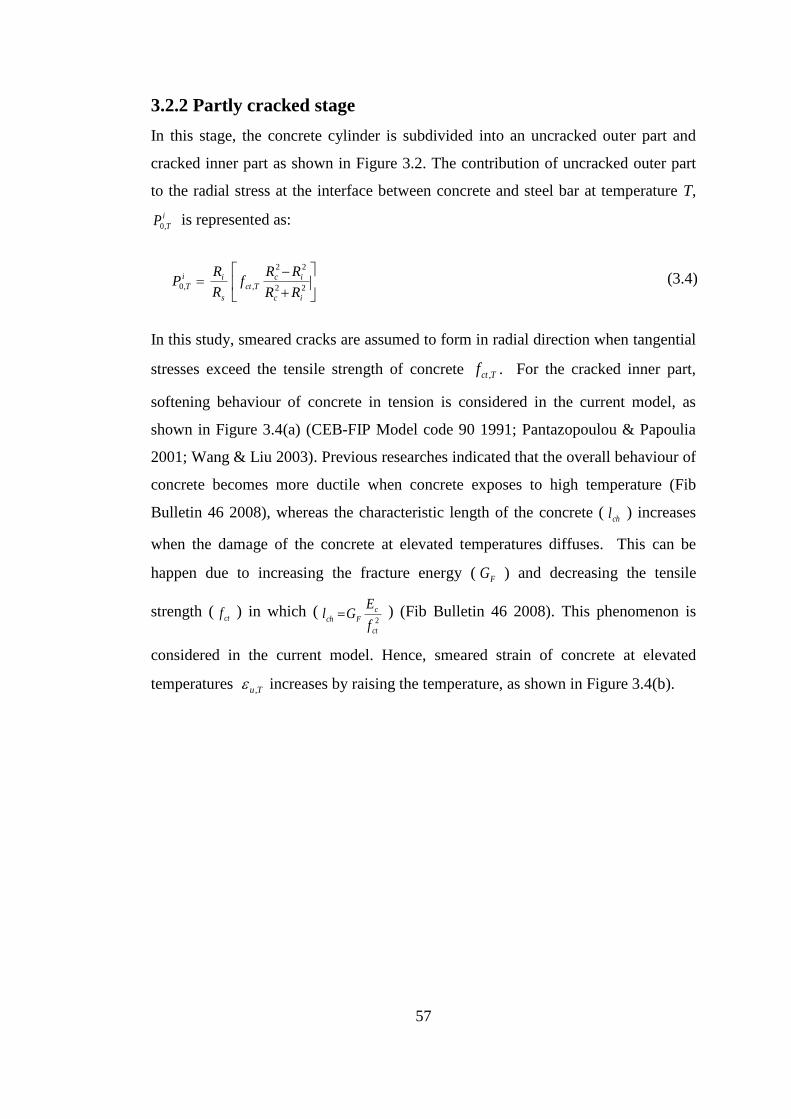
57
3.2.2 Partly cracked stage
In this stage, the concrete cylinder is subdivided into an uncracked outer part and
cracked inner part as shown in Figure 3.2. The contribution of uncracked outer part
to the radial stress at the interface between concrete and steel bar at temperature T,
i
TP ,0 is represented as:
22
22
,,0
ic
icTct
s
ii
TRR
RRf
R
RP (3.4)
In this study, smeared cracks are assumed to form in radial direction when tangential
stresses exceed the tensile strength of concrete Tctf , . For the cracked inner part,
softening behaviour of concrete in tension is considered in the current model, as
shown in Figure 3.4(a) (CEB-FIP Model code 90 1991; Pantazopoulou & Papoulia
2001; Wang & Liu 2003). Previous researches indicated that the overall behaviour of
concrete becomes more ductile when concrete exposes to high temperature (Fib
Bulletin 46 2008), whereas the characteristic length of the concrete (chl ) increases
when the damage of the concrete at elevated temperatures diffuses. This can be
happen due to increasing the fracture energy ( FG ) and decreasing the tensile
strength (ctf ) in which (
2
ct
c
Fchf
EGl ) (Fib Bulletin 46 2008). This phenomenon is
considered in the current model. Hence, smeared strain of concrete at elevated
temperatures Tu , increases by raising the temperature, as shown in Figure 3.4(b).
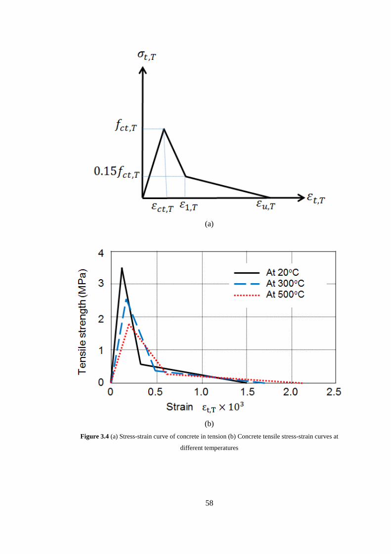
58
(a)
(b)
Figure 3.4 (a) Stress-strain curve of concrete in tension (b) Concrete tensile stress-strain curves at
different temperatures

59
Therefore, the tensile stress of concrete Tt , can be determined as:
TctTtTtTTt E ,,,,0, (3.5)
TTtTct
TctT
TctTt
TctTt f ,1,,
,,1
,,
,,
85.01
(3.6)
TuTtT
TTu
TtTu
TctTt f ,,,1
,1,
,,
,, 15.0
(3.7)
where Tu , is the smeared strain of concrete at elevated temperatures when tensile
stress equal to zero, and TctTu ,, . In order to determine the softening branch of
stress-strain curve in tension, different values of were used in previous
researches. In the most cases, selection of the factor was chosen based on the
type of the problem and experiences of the researchers. The range of 10-25 can be
adopted for the factor based on a study by (Barzegar & Schnobrich 1986). For this
reason, the sensitivity of factor on the proposed model is explained in this
research. Three values of factor ( 10 , 15 and 25 ) at temperatures of
300 oC and 500
oC are conducted. The results are shown in Figure 3.5. It can be seen
from the figure that the value of factor has an effect on the bond stress-slip curve
at different temperatures. Therefore, it is reasonable to use 15 as an optimum
value in this research. Also TuT ,,1
9
2 is used (Barzegar & Schnobrich 1986;
Huang 1995).
Tt , is the average tangential strain at a radial distance r, which can be expressed in
terms of tangential elongation,
t as:
r
tTt
2, (3.8)
When the tensile stress Tt , reaches to the maximum tensile strength of concrete
Tctf , , just before the cracks form at a radial distance iRr (see Figure 3.2 and Figure
3.3), by neglecting the effect of Poisson’s ratio, the total elongation can be expressed
as (Wang & Liu 2003):

60
TctiTtt Rr ,, 22 (3.9)
Substitute Equation (3.9) into Equation (3.8) to obtain:
Tcti
Ttr
R,, (3.10)
At , sRr
Tct
s
it
R
R,0, (3.11)
where 0,t is the smeared tangential strain of concrete at the rebar interface when
si RRr ; Ef TTctTct ,0,, / , and TE ,0 is the initial modulus of elasticity of the
concrete at elevated temperatures.
Figure 3.5 Influence of on the current model at different temperatures: (a) At 500oC, (b) At 300
oC
Now, the total radial stress at the interface between concrete and steel bar i
TP equals
to the contribution of uncracked outer part to the radial stress i
TP ,0 plus the
contribution from the cracked inner part, in which the softening behaviour of
concrete is taken into account. Hence, i
TP can be calculated as:
i
s
R
RTt
s
i
T
i
T drrR
PP ,,0
1 (3.12)

61
The integration in Equation (3.12) can be solved by using Equations (3.5)-(3.7)
which can be expressed as (Wang & Liu 2003):
TTtTct
s
iTcti
siTctT
TctT
TctR
RTt
R
RR
RRf
drrIi
s,1,,
,
,,1
,,1
,
,ln85.0
15.0
(3.13)
TuTtT
Tct
T
Tcti
T
TctTi
TctT
TctT
Tct
Ts
Tcti
Tcti
T
TsTcti
Tu
TTu
TctR
RTt
R
R
f
R
RR
RR
fdrrI
i
s
,,,1
,
,1
,
,1
,,1
,,1
,,1
,
,1
,
,
,1
,1,
,
,1,
,
,
ln85.0
15.0
ln
15.0
(3.14)
3.2.3 Entirely cracked stage
In this stage, the concrete cover is completely cracked, the confining action of
concrete is diminished and the splitting failure is occurred. Hence, the bond stress
between the concrete and the steel bar becomes very little or negligible.
After calculation of Equation (3.12), the bond stress can be determined as (Tepfers
1979; Bigaj 1999; Pothisiri & Panedpojaman 2012; Pothisiri & Panedpojaman
2013):
coti
T
i
T P (3.15)
where is the effective face angle (see Figure 3.1) which can be taken in the range
of 30o to 45
o (Tepfers 1979; Nielsen & Bicanic 2002). Hence, it is assumed that
042 in the current model if is not given in the test based on the rib face angle
of the rebar.
In the current model, the effect of high temperature on the bond characteristics is
considered by taking into account the degradation of concrete properties at elevated
temperatures. The concrete properties at ambient temperature specified in Eurocode
2 EN 1992-1-1 (CEN 2004) are used. The elastic modulus of concrete at elevated

62
temperatures TE ,0 is calculated based on Eurocode 2 EN 1992-1-2 (CEN 2004).
However, the degradation of the concrete tensile strength at elevated temperatures
Tctf ,
specified in Eurocode 2 EN 1992-1-2 is not adopted in this model. This is
mainly due to the Eurocode 2 EN 1992-1-2 (CEN 2004) assumed the concrete tensile
stress reached to the zero 0, Tctf when the concrete temperature is higher than
600 oC. Hence, the degradation of the tensile strength for concrete at elevated
temperatures proposed by Aslani and Bastami (2011) is adopted in this study (see
Equation (2.3)).
One of the main contributions of this research is to develop a procedure for
calculating the slippage of the rebar and to establish a relationship between the bond
stress and bond slip. In order to determinate the bond-slip relationship, the slip for
the maximum bond maxS (see Figure 3.6) that obtained from the bond stress-slip
model in CEB- FIP Model Code 90 (CEB-FIP Model code 90 1991) is used with the
maximum bond stress max that obtained from the partially cracked thick wall
cylinder theory described above to form the bond-slip relationship. Hence, the slip
of the rebar can be determined by considering the maximum slip maxS at the
maximum bond stress point max . In the current model maxS equals to 0.6 mm for
splitting failure at concrete cover C = db, and 1.0 mm for pull-out failure when
concrete cover bdC 5 when good bond conditions are assumed (CEB-FIP Model
code 90 1991), where db is the rebar diameter. By taking linear interpolation for
5/1 bdC , maxS can be determined for different values of concrete cover and
rebar’s diameters as:
11.06.0max
bd
CS (3.16)
Hence 0.16.0 max S

63
Figure 3.6 Proposed curves: (a) Bond stress-slip curve (b) Bond stress - Ri curve
As shown in Figure 3.6 (b) max can be found when the tangent slop at the peak
value of the bond stress-Ri curve equals to zero, that is:
0.01
1
ii
i
T
i
T
i
i
T
RRRd
d (3.17)
The bond stress-slip curve (Figure 3.6 (a)) and bond stress - Ri curve (Figure 3.6 (b))
have two parts. The first part of the curves, where sk SS 0 , where s is the
bond stress at si RR and 1 i
Ts which can be calculated from Equation (3.15).
The slip sS at s can be calculated as:
/1
max
max
SS s
s (3.18)
where is assumed to be 0.4 (CEB-FIP Model code 90, 1991).
Then, the bond stress at elevated temperatures k
T can be calculated as:
max
maxS
Sk
T (3.19)
For the second part of bond stress-slip curve and bond stress - Ri curve, where
si SS and si RR respectively, the relationship between
iR and Si can be

64
taken as a liner relationship (see Figure 3.7) (Sakai et al. 1999). The slop m of the
line in Figure 3.7 can be calculated as:
s
s
i
i
SS
RR
S
Rm
max
max (3.20)
Then, the slip for the second partiS is:
s
sii S
m
RRS
(3.21)
where i=1, 2, 3 … n, and n is the total number of the steps atci RR , then n
Tfail
at the end of the numerical calculations.
Figure 3.7 The relationship between the slip and Ri
The calculation procedure proposed in this model for determining the bond stress-
slip curve at each temperature step can be summarised as following:

65
(1) Calculate the bond-stress i
T and bond-slip iS for the second part of bond
stress-slip curve ( failis SSS and cis RRR ) (see Figure 3.6):
n
RRR sc
i = 1, 2, 3, …n:
RRR ii 1
Calculate i
TP ,0 (Equation (3.4));
Calculate i
TP (Equation (3.12));
Calculate i
T (Equation (3.15))
Calculate max and maxR (Equation (3.17))
Calculate sS (Equation (3.18))
i = 1, 2, 3, …n:
Calculate iS (Equation (3.21))
(2) Calculate the bond-stress k
T and bond-slip kS for the first part of bond
stress-slip curve (si SS 0 ) (see Figure 3.6):
n
SS s
k = 1, 2, 3, …n:
SSS kk 1
Calculate k
T (Equation (3.19))
3.3 Incorporated bond stress–slip model into Vulcan software
In order to demonstrate the robustness and accuracy of the model proposed above,
the developed bond stress-slip model has been incorporated into the VULCAN
software (Huang et al. 2009) for simulating the bond characteristics between
concrete and reinforcing steel bar at elevated temperatures. Huang (2010) has
developed a two-node bond-link element within the VULCAN to consider the bond
characteristics between concrete and steel bars under fire conditions. As shown in
Figure 3.8, the bond link element has two nodes with zero length. Each node of the
element has three translational degrees of freedom wvu ,, and three rotational

66
degrees of freedom zyx ,, , where x, y, z are the local coordinates of the steel
bar in which x is the direction of longitudinal axis of the reinforcing steel bar
element. It is assumed that the slip between reinforcing steel and concrete is related
only to the longitudinal axis direction (x-direction) (see Figure 3.8 (a)). Hence, the
bonding force xTF ,
between the concrete and reinforcing steel bar for the bond
element is obtained as:
TxT AF , (3.22)
where A is the contact area between the concrete and the reinforcing steel bar LUA
, where U is the perimeter of the steel bar and L is length of the steel bar which
contributes to the node connected by the bond element.
Figure 3.8 Bond-link element: (a) 2-D Coordinates (b) 3-D Coordinates
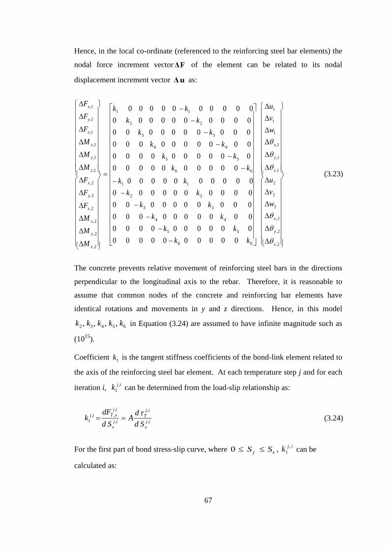
67
Hence, in the local co-ordinate (referenced to the reinforcing steel bar elements) the
nodal force increment vector FΔ of the element can be related to its nodal
displacement increment vector uΔ as:
2,
2,
2,
2
2
2
1,
1,
1,
1
1
1
66
55
44
33
22
11
66
55
44
33
22
11
2,
2,
2,
2,
2,
2,
1,
1,
1,
1,
1,
1,
0000000000
0000000000
0000000000
0000000000
0000000000
0000000000
0000000000
0000000000
0000000000
0000000000
0000000000
0000000000
z
y
x
z
y
x
z
y
x
z
y
x
z
y
x
z
y
x
w
v
u
w
v
u
kk
kk
kk
kk
kk
kk
kk
kk
kk
kk
kk
kk
M
M
M
F
F
F
M
M
M
F
F
F
(3.23)
The concrete prevents relative movement of reinforcing steel bars in the directions
perpendicular to the longitudinal axis to the rebar. Therefore, it is reasonable to
assume that common nodes of the concrete and reinforcing bar elements have
identical rotations and movements in y and z directions. Hence, in this model
65432 ,,,, kkkkk in Equation (3.24) are assumed to have infinite magnitude such as
(1015
).
Coefficient 1k is the tangent stiffness coefficients of the bond-link element related to
the axis of the reinforcing steel bar element. At each temperature step j and for each
iteration i, ijk ,
1 can be determined from the load-slip relationship as:
ij
x
ij
T
ij
x
ij
xTij
Sd
dA
Sd
dFk
,
,
,
,
,,
1
(3.24)
For the first part of bond stress-slip curve, where sj SS 0 , ij
k,
1 can be
calculated as:

68
1
max
,
max
max,
1
j
ij
x
j
jij
S
S
SAk (3.25)
For the second part of bond stress-slip curve, where sj SS , a numerical
differentiation method was used to calculate coefficient jk1 .
j
i
j
i
j
i
j
iij
SSAk
11
11,
1
(3.26)
Using incremental analysis, the increment of bond force ij
xTF ,
, can be related to the
increment of slip, ij
xS , using the tangent stiffness relationship, that is:
ij
x
ijij
xT SkF ,,
1
,
, (3.27)
in which
ijijij
x uuS ,
1
,
2
, (3.28)
where iju ,
1 and iju ,
2 are the increments of displacement in the direction of j
xTF ,
at the nodes 1 and 2 of the bond-link element respectively.
As shown in Figure 3.8, in the current model a reinforced concrete member is
represented as an assembly of plain concrete beam elements, reinforcing steel bar
elements and bond-link elements. Both of the plain concrete beam elements and
reinforcing steel bar elements are modelled using the 3-node beam element
developed by Huang et al. (2009), in which the thermal expansions of concrete and
steel bars are considered. Hence their effect in the direction of longitudinal axis of
the reinforcing bar on the bond-link element developed in this project is taken into
account. However, the thermal expansions of both concrete and steel in the radius
direction of the steel bar have not been considered in the current model for
simplicity. This is because the strain compatibility at the interface between steel bar
and surrounding concrete is not always maintained when the pull-out load is applied
(Pothisiri & Panedpojaman 2012), especially when the pull-out load reaches to the
capacity of the bond. Also, the reduction in the steel bar’s diameter due to the

69
Poisson’s effect during the pull-out load could compensate the influence of the
differential thermal expansion between the steel bar and concrete.
As mentioned above the plain concrete beam is modelled using the 3-node beam
element. The cross-section of the beam element is subdivided into a number of
segments to consider the temperature variation within the cross-section. Hence, in
principal the temperature variation within the concrete rings around the bars (see
Figure 3.2Figures 3.2 and 3.3) can be considered in the current model. However, in
the following validation section it is assumed that the temperatures of the concrete
rings around the bars are uniform and equal to the temperature of the reinforcing bar
for simplicity. This is a reasonable assumption for all pull-out tests (Pothisiri &
Panedpojaman 2012).
3.4 Validations
The proposed model presented above was validated using a series of previous
experimental results at both ambient and elevated temperatures. This section consists
of two parts: the first part is to make a comparison between the predicted bond
stress-slip curves and previous experimental pull-out test results at both ambient and
elevated temperatures; the second part of the verification is to validate the response
of VULCAN program after incorporation of the developed bond stress-slip model
using bond-link element. In this case, reinforced concrete beams were modelled with
full and partial bond between the concrete and steel bars to study the effect of bond
on the response of the beam at ambient and elevated temperatures.
3.4.1 Validations of the bond stress–slip model
3.4.1.1 Bond stress–slip curve at ambient temperature
Table 3.1 gives information about the experimental tests carried out by Xiao and
Falkner (2007), John and Bhupinder (2013) and Lee and Noguchi (2002) to study the
bond-slip at ambient temperature. In the Table 3.1, lb is the embedded length of the
rebar inside the specimens and db is the diameter of the rebar. All material properties
and geometric details of the specimens that mentioned in Table 3.1 were used as an
input data for modelling the bond-slip in this section. Figure 3.9 (a) to (f) show the
comparison of the predicted and measured bond stress-slip curves based on the tests.

70
It is clear from the figures that there is an acceptable agreement between the
predictions from the current model and the experimental results. This can confirm
that the proposed model can be used for predicting the bond stress-slip curve
between concrete and reinforcing steel bars at ambient temperature.
Table 3.1 Details of pull-out test in previous experiments at ambient temperature
Reference Specimens fck,20
oC
(MPa)
Bar
diameter
db(mm)
Rc (mm)
C/db lb /db Rib face
angle
(degrees)
(Xiao & Falkner, 2007)
(John Robert Prince & Bhupinder, 2013)
(Lee & Noguchi,
2002)
RAC-II-0
A12R0 A16R0 A20R0 A25R0
-
34.0
36.9
24.7
10
12 16 20 25
13
50
50 50 50 50
45
4.0
3.67 2.6 2.0 1.5
3.0
5.0
5.0 5.0 5.0 5.0
6.0
55o
45
o
36o
41o
51o
-
(a) Specimen RAC-II-0 (Xiao & Falkner 2007)

71
(b) Specimen A12R0 (John Robert Prince & Bhupinder 2013)
(c) Specimen A16R0 (John Robert Prince & Bhupinder 2013)
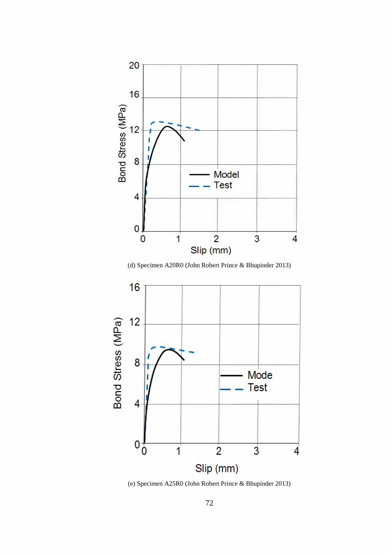
72
(d) Specimen A20R0 (John Robert Prince & Bhupinder 2013)
(e) Specimen A25R0 (John Robert Prince & Bhupinder 2013)

73
(f) Test conducted by (Lee & Noguchi 2002)
Figure 3.9 Comparison of predicted and measured bond stress-slip curves at ambient temperature
3.4.1.2 Bond stress–slip curve at elevated temperatures
The details of pull-out tests at elevated temperatures used in this validation are
summarised in Table 3.2. As mentioned before that the testes about the bond
characteristics between the concrete and steel bars at elevated temperatures are
limited. Hence, the proposed model was validated using the available experimental
results of pull-out testes at elevated temperatures. All the material properties and
geometries of the specimens in the tests were used as an input data for modelling the
bond between the concrete and reinforcement at elevated temperatures.
The first test was conducted by Diederichs and Schneider (1981). This test was used
for bond validation at elevated temperatures in this project. The details of the test
were; deformed steel bar of 16 mm and the specimens were made with a bond
embedded length of 80 mm and concrete cover of 78 mm. The temperatures within
the test were in the range of 20 oC to 800
oC with heating rate of 1
oC/min.
Figure 3.10 (a) illustrates the comparison of predicted and measured bond stress-slip

74
curves for different temperatures. It can be seen from the figure that a good
correlation between the prediction from the model and the result from the teste was
achieved. It is clear that the strength of the bond was degraded significantly by
increasing the temperatures.
Table 3.2 Details of pull-out tests in previous experiments at elevated temperatures
Reference fck,20oC (MPa)
Bar diameter
db (mm) Rc (mm) C/db lb /db
(Diederichs & Schneider,
1981)
(Morley & Royles, 1983)
(Haddad & Shannis, 2004)
(Haddad , et al., 2008)
45.0
29.0
58.8
62.3
16
16
16
16
16
18
20
86
63
54
40
33
41
50
4.88
3.44
2.88
2.0
1.56
1.78
2.0
5.0
2.0
2.0
2.0
2.0
8.3
7.5
(a) Tested by (Diederichs & Schneider 1981)

75
(b) Tested by (Morley & Royles 1983)(𝑑𝑏 = 16mm, concrete cover 55 mm)
(c) Tested by (Morley & Royles 1983)(𝑑𝑏 = 16mm , concrete cover 46 mm)

76
(d) Tested by (Haddad & Shannis 2004)
(e) Tested by (Haddad et al. 2008)
Figure 3.10 Comparison of predicted and measured bond stress-slip curves at elevated temperatures

77
The second test was carried out by Morley and Royles (1983). The temperatures
within these tests were in the range of 20 oC-750
oC with heating rate of 2
oC/min.
The lengths of the samples were 300 mm with a rebar embedded length of 32 mm.
The details of the tests are given in Table 3.2. Figure 3.10 (b) and Figure 3.10 (c)
show the comparison between the results from the testes and the predictions from the
current model for concrete covers of 55 mm and 46 mm, respectively. It is evident
that the predictions from current model are in the reasonable agreement with the
testes data.
Another experimental test was conducted by Haddad and Shannis (2004) which was
used for validation of the bond model at elevated temperatures. In these test, special
cylindrical moulds of 82 mm diameter with a circular opening of 20 mm at the bases
were used to cast the pull out specimens. The steel bar was 18 mm in diameter with
imbedded length of 150 mm. The temperatures of the tests were 23 oC, 600
oC and
800 oC with heating rate of 20
oC/min. The details of the test are given in Table 3.2.
A comparison between the current model and the results from the test is shown in
Figure 3.10 (d). Again, reasonable agreement between the curves of the bond model
and the curves from the testes were achieved.
Finally, a test was done by Haddad et al. (2008) has been adopted for further
validation of the current model. The specimens in this test were in cuboid shape with
dimensions of (100 x 100 x 400 mm). The steel bars of 20 mm with embedded
length of 150 mm were used in this study. The range of the test temperatures was 23
oC to 700
oC. Figure 3.10(e) presents the comparison between the predictions from
the current model and the results that achieved from the testes. It can be seen from
the figure that the bond strength predicted by the current model is higher than the
result from the teste at ambient temperature. However, there is very little difference
between the tests at 23 oC compared with 350
oC. This is contradicted with the tested
results generated by other two researchers presented above.

78
3.4.2 Validations of the bond-link element with new developed bond
stress–slip model
As mentioned in Section 3.3, the developed bond stress-slip model has been
incorporated into the VULCAN software (Huang et al. 2009) for simulating the bond
characteristics between concrete and reinforcing steel bar at ambient and elevated
temperatures. In this section, three different types of tests were adopted to validate
the response of the reinforced concrete members that modelled with full and partial
interaction between the concrete and steel bar using bond-link element approach.
3.4.2.1 Modelling pull-out test at ambient temperature
Viwathanatepa et al. (1979) conducted several pull-out tests at the University of
California in 1979. One specimen was used as a reference for validation. In this test,
the reinforcing bar was 25 mm diameter with anchorage length of 635 mm through
the concrete specimen. The specimen was subjected to a monotonic pull-out load
under displacement control at one end only. The tested material properties of
concrete and steel are as follows: the concrete cylinder compressive strength is
fck=32.4 MPa, yield strength of the reinforcing steel bars is fy=468.4 MPa. These
material properties and the specimen details were used as an input data for the
modelling the beam. The finite element mesh for modelling this test involved 4
three-node plain concrete elements, 4 three-node reinforcing steel bar elements. The
nodes of the concrete elements were connected to the nodes of the steel bar elements
by the two-node bond-link elements. Hence, total of 9 two-node bond-link elements
were used in this case.
In this validation the predicted steel stresses from VULCAN output were compared
with the teste data, as well as compared with the results from an analytical study
generated by Viwathanatepa et al. (1979). Figure 3.11(a) to (c) show the stress
distribution along the anchored length of the reinforcing steel bar at three different
load levels. It is clear from the figures that the results generated by the current model
agree well with the teste results. To demonstrate the robustness of the current model,
Figure 3.12 shows the predicted bond stress field along the anchored length for
different loaded end slips. Also Figure 3.13 presents the predicted end slips versus
total pull out load for the test. These results indicated that the strength of the bond

79
between concrete and reinforcing steel bar plays a very important role which can
effect on the load capacity of reinforced concrete structural members.
(a) End stress=138 MPa
(b) End stress=276 MPa

80
(c) End stress=414 MPa
Figure 3.11 Comparison between the predicted and tested stress distributions along anchored
reinforcing steel bar (Viwathanatepa et al. 1979)
Figure 3.12 Predicted bond stress distributions corresponding to different end-slips for test
(Viwathanatepa et al. 1979)

81
Figure 3.13 Predicted end-slips vs pull-out force for the test (Viwathanatepa et al. 1979)
3.4.2.2 Modelling simply supported RC beam at ambient
temperature
In order to examine the capability of the developed model, a simply supported
reinforced beam J4 tested by Burns and Siess (1962) was used for the validation.
Figure 3.14 illustrates the details of J4 beam. The material properties of the concrete
was fck=33.34 MPa and the reinforcing steel bars was fy=309.6 MPa as a yield
strength and elastic modulus of Es=203404 MPa. The beam was modelled with 2 x
25.4 mm reinforcing steel bars. Those material properties were used as the input data
for modelling the beam. Due to the symmetry of the beam, only half of the beam was
modelled in this study. For modelling the beam J4, 4 three-node plain concrete
elements, 8 three-node reinforcing steel bar elements with 198.2 mm off-set below
the central reference axis and 63.5 mm right and left referenced to the central
reference axis, and 18 bond-link elements were employed. Figure 3.15 shows the
comparison of predicted and measured mid-span deflections of J4 beam with
different bond conditions. In the figure, it was assumed for the case of perfect bond
that there is no slip can occur between the steel bar and surrounding concrete, while
the case of bond-slip the interaction between steel bar and concrete was considered

82
by using bond-link element that developed in this study. It is evident that the bond-
slip of the reinforcing steel bars has a negligible effect on the load-deflection
response at room temperature.
Figure 3.14 Details of J4 beam tested at ambient temperature (Burns & Siess 1962)
Figure 3.15 Comparison of predicted and measured mid-span deflections of J4 beam (Burns & Siess
1962)

83
3.4.2.3 Modelling fire tests of RC beams
Lin et al. (1987) curried out a series of tests on reinforced concrete beams under fire
conditions. Two types of heating curves were adopted in these tests; ASTM standard
fire curve and Short Duration High Intensity (SDHI) fire curve. In this validation,
four beams of two groups were modelled. The first group Beam-1 and Beam-3 was
heated using ASTM standard fire curve and the second group Beam-5 and Beam-6
was subjected to the SDHI fire. The details of the beam-1, beam-3, beam-5 and
beam-6 used for modelling are shown in Figure 3.16. The concrete compressive
strengths of beam 1, 3, 5 and 6 were fck=27.68 MPa, fck=31.5 MPa, fck=33.37 MPa
and fck=34.54 MPa respectively. The yield strength of tested steel bars were
fy=487.27 MPa for the 22.2 mm steel bar diameter and fy=509.54 MPa for 25.4 mm
steel bar diameter. Degradation of the concrete compressive strength and the steel
bars yield strength at elevated temperatures specified in EN 1992-1-2 (CEN 2004)
were adopted for concrete and steel bar elements.
Figure 3.16 Details of tested beams in fire (Lin et al. 1987)
810 1016 1016 1016 1016 1016 306
300
360 3251 838
940
6100 1830
Q
Left Right
58
56
306
56
58
534
58 58
228
4 - #8
4 - #7
#3@ 216 (Left)
146 (Right)
Beam No. 1, 5
77
56
268
56
77
534
77 77
228
4 - #8
4 - #7
Beams No. 3, 6
All dimensions in mm
P P P P P P P 0
#3@ 216 (Left)
146 (Right)
Surface exposure to fire conditions
1 2
3 4
1 2
3
4

84
In order to model the tested beams using VULCAN software, two phases should be
followed to perform the analysis. The first phase was to perform the thermal
analysis. As shown in Figure 3.16 the arrangement of reinforcing steel bars in the
tested beams varied along the length of the beam. To perform the thermal analysis in
this study, the cross-sections of the beams were divided into 448 segments (28 rows
x 16 columns). The steel bars were represented as steel segments within the cross-
section of the beam and varied along the length of the beam based on the tested
beams. The thermal analysis was conducted to predict temperature histories of each
segment within the beam cross-sections. There are four layers of main reinforcing
steel within the cross-sections as shown in Figure 3.16. For presenting the results of
the thermal analysis, the reinforcing steel layers are denoted in sequence from
bottom to top as layers 1 to 4. The predicted temperature histories of the main
reinforcing steel layers for beams-1 and beam-5 are shown in Figure 3.17 and Figure
3.18 respectively. It is evident from the figures that reasonable agreements have
been achieved from the thermal analysis by compare the temperature history of the
test with the predicted temperature history for the steel bar layers.
Figure 3.17 Comparison of predicted and measured temperatures of four main reinforcing steel layers
for Beam 1 (Lin et al. 1987)

85
Figure 3.18 Comparison of predicted and measured temperatures of four main reinforcing steel layers
for Beam 5 (Lin et al. 1987)
Predicted temperatures histories from the thermal analysis for each concrete and
steel segment were used as the temperature input data for the structural analysis.
Hence, same segmentations of the beams cross sections used in the thermal analysis
were adopted for the plain concrete elements in the structural analysis, in which the
volumes occupied by the steel bars were represented as void segments. The
temperatures of the reinforcing steel bars were represented by the temperatures of the
steel segments at related locations within the cross-section. In this analysis, a total of
10 three-node plain concrete elements with 448 segments, 48 three-node reinforcing
steel bar elements with off-set from the central reference axis of the beam and 104
bond-link elements were employed for modelling the whole beam. As shown in
Figure 3.16, the load P was kept constant at 44.48 kN during each fire test, although
the cantilever force varied as the test progressed.
Due to the beam was continued over the right-hand support as shown in Figure 3.16,
the maximum vertical deflection of the beam was formed around the position 2600
mm from the left-hand support. The comparison of predicted and measured
maximum deflections of Beam 1 and Beam 3 under ASTM fire condition are shown

86
in Figure 3.19 and Figure 3.20 respectively. Again, these two beams were modelled
twice to consider the case of perfect bond and bond-slip conditions. For the perfect
bond condition, it was assumed that there is no slip can occur between the steel bar
and surrounding concrete. However, partial interaction between reinforcing steel bar
and concrete was considered by using current bond-link element for modelling the
case of bond-slip condition. Under ASTM standard fire condition, it is evident from
the figures that before 120 min test time the behaviours of the beams that modelled
with full or partial bond conditions are almost identical. This is due to the average
temperature at bond between concrete and reinforcing steel bar is less than 400oC
(see Figure 3.17). Hence, the strength of the bond does not decrease significantly. As
explained previously in section 3.4.1.2 the bond between the concrete and
reinforcement decreases significantly at temperatures 400oC to 600
oC. However, the
influence of the bond became significant when the test time beyond 180 min in
which the average temperature at the bond was above 500oC as shown the Figure
3.17.
Figure 3.19 Comparison of predicted and measured maximum deflections of Beam1 (ASTM Fire)
(Lin et al. 1987)

87
Figure 3.20 Comparison of predicted and measured maximum deflections of Beam3 (ASTM Fire)
(Lin et al. 1987)
Figure 3.21 and 3.22 illustrate the comparison between the predicted and tested
maximum deflections of Beam 5 and Beam 6 under SDHI fire condition. It can be
seen that the influence of the bond conditions is not significant. This is due to the
maximum temperature of the bond is less than 400oC (see Figure 3.19). From the
validations, it is evident that the new bond-link element with the developed bond
stress-slip model is capable to consider the influence of bond characteristics between
concrete and reinforcing steel bars on the structural behaviours of reinforced
concrete structural members at ambient and under fire conditions. This study
indicates that for fire resistance design of reinforced concrete structures the perfect
bond assumption is un-conservative and it is important to consider the influence of
bond within the concrete design under fire conditions.

88
Figure 3.21 Comparison of predicted and measured maximum deflections of Beam5 (SDHI Fire) (Lin
et al. 1987)
Figure 3.22 Comparison of predicted and measured maximum deflections of Beam6 (SDHI Fire) (Lin
et al. 1987)

89
3.5 Conclusions
In this chapter a numerical model has been developed to simulate the bond-slip
characteristic between the concrete and reinforcing steel bar at ambient and elevated
temperatures. The model is based on the thick-wall cylinder theory with considering
of the partially cracked concrete cover and the smeared crack of concrete in tension.
Hence, the model takes into account the splitting failure of concrete cover. The
degradation of the bond strength at elevated temperatures is related to the concrete
material properties changed with temperature. The developed bond stress-slip model
has been incorporated into VULCAN software using the two-node bond-link element
approach to consider the influence of bond characteristic on structural behaviours of
reinforced concrete structural members in fire. A series of validations have been
conducted using the previous tested results generated by different researchers.
Reasonable agreements have been achieved between the predicted results from the
model and the experimental data. Based on this study, the following conclusions can
be drawn:
• The model presented in this chapter is able to predict the bond-slip characteristic
between the concrete and reinforcing steel bar at ambient and elevated
temperatures. The model takes into account the variation of concrete properties,
concrete covers and the geometries of rebar.
• The study indicated that the strength of the bond between concrete and reinforcing
steel bars plays a very important role that can affect the fire resistance of
reinforced concrete structures, especially when the temperature of the reinforcing
steel bar is high (more than 400°C). Therefore, the assumption of the perfect bond
condition for the analysis of reinforced concrete structures under fire conditions is
un-conservative.
• For fire engineering design the failure of bond between concrete and reinforcing
steel bar, particularly in beams with little or no continuity, can be the key criterion
for fire resistance, but this clearly needs further parametric studies before general
rules can be proposed.

90
Chapter 4 Behaviour of the bond between
prestressed strands and concrete in fire
After understanding the effect of the bond stress-slip on the structural behaviour of
the reinforced concrete members under fire conditions, it is important to study the
bond stress-slip in prestressed concrete structures. Hence, this chapter is dedicated to
develop a new analytical model to simulate the bond stress-slip between concrete
and strands in prestressed concrete members at elevated temperatures. Influence of
the bond-slip on the response of prestress concrete members under fire conditions is
also investigated.
4.1 Introduction
Prestressed concrete (PC) members have obtained wide popularity in current
building constructions. PC members can be constructed by utilizing unbonded or
bonded strands with concrete. For bonded PC members, the bond is essential for the
success of prestressing system. The bond in PC members may be categorized as
transfer bond and flexural bond. During the manufacture of PC members, strands are
initially prestressed using jacks at the ends abutments. The concrete is casted and
cured then the strands are cut. Initial tensioning of the strand causes a reduction in
the diameter of the strand due to Poisson’s effect. After concrete reaches sufficient
strength, the strands are released from the abutments, and the stress in the strands at
the free ends of the members returns to zero. With this reduction of the strand
stresses, the diameter of the strand expands along the transfer length. Therefore,
wedging action between the strand and concrete will occur due to lateral expansion
(called Hoyer effect). This effect leads to improve the bond performance over the
transfer bond length (Abrishami & Mitchell 1993).
From the literature, to determine the bond for the flexural bond length, pull-out tests
have been conducted by casting the concrete surround the strand then the strand is
pulled-out from the concrete with measuring the pull-out force versus the slip.
However, the bond for the transfer bond length can be obtained by applying initial
prestress on the strand, and then casting the concrete until the time of test, then
releasing the stress from the strand gradually with recording of stress released versus
91
the slip (Abrishami & Mitchell 1993; CEB-FIP-Bulletin10 2000). For the bonded PC
structural members, transferring the force from the strand to the concrete is through
the end anchors together with the bond between strand and concrete. Therefore,
bonded PC beams are more robust structural members at ambient temperature.
However, previous research indicated that compared to normal reinforcing steel,
prestressed steel wires are more sensitive to elevated temperatures due to the stress
level in prestressing wires is very high (Hou et al. 2015).
Structural fire safety is one of the most important considerations in building
applications. In concrete beams, fire resistance is generally assessed by evaluating
the bending failure only. However, bond failure can be dominated in bonded PC
members. Concrete tensile strength is significantly affected by high temperatures
results in a big reduction in the shear capacity of the concrete and bond strength.
Also at high temperatures, internal stresses due to differential thermal elongations
play a role on the occurrence of concrete cracks at the interface surrounding the
rebar, which can decrease the bond stress (Fellinger, et al. 2003). The conventional
approach of evaluating fire resistance through fire tests is expensive. Therefore, an
alternative to fire tests is the use of numerical modelling for evaluating fire
resistance of the prestressed concrete members. Numerical model allows the
researcher to incorporate various parameters in an efficient and cost-effective way
during the analysis (Kodur & Shakya 2014).
Previous research indicated that concrete structures begin losing strength rabidly
when temperature reaches higher than 300oC (Rivera et al. 2016). For the prestress
steel, the loss of strength occurs at lower temperatures compared to the normal steel
rebar, in which a considerable reduction can be occurred in prestress steel strength at
temperatures 300oC–400
oC (ASHI Reporter 2007). At present, a number of
investigations have been conducted to study the bond behaviour between prestressed
strands and concrete at ambient temperature (Abrishami & Mitchell 1993; Lundgren
2002; Gustavson 2004; Galvez et al. 2009; Vázquez-Herrero et al. 2013). However,
there are very limited researches conducted to investigate the bond-slip characteristic
between prestressed strands and concrete at elevated temperatures. Hence, the main
objectives of this chapter are to:

92
Develop a robust model for modelling the bond-slip between concrete and
strands for prestressed concrete structures in fire. This model can be used to
predict the bond stress-slip for three wire and seven-wire strands with smooth
or indented surface at elevated temperatures.
Incorporate the bond-slip model into the 3D finite element program
VULCAN to model prestressed concrete structures under fire conditions.
Validate the model against previous test results.
4.2 Analytical model
In pretensioned concrete members, there are two distinct regions with different bond
characteristics: the transfer length region and flexural length region. Figure 2.6
illustrates the behaviour of a prestress beam and the state of the strands stresses
within the beam before and after applying the external load. Figure 2.6(a) shows the
pretensioned reinforced concrete beam, and Figure 2.6(b) gives the variation of
stresses in the pretensioned strand along an unloaded beam after the prestress is
released from the strand and before applying the external load. Figure 2.6(c) shows
the variation of stresses in the strand for the same beam after it is subjected to
external load (Abrishami & Mitchell 1993). The transfer length lt, as shown in Figure
2.6 (b) is the distance from the end of the beam where the strand stress is zero to the
point where the strand stress reaches to the maximum level for unloaded beam. The
transfer length lt can be taken as (50 ds) (CEB-FIP-Bulletin10 2000). The flexural
length lf is the length that starts from the end of the transfer length to the point in
which the ultimate stress can be developed after loading the beam (see Figure 2.6
(c)).
When concrete is casted around the strand in prestressed concrete structures, the
concrete forms an envelope or sleeve surround the strand. The hardened concrete
mimics the shape of the strand. When the strand is pulled through the concrete,
movement is resisted by the concrete keys acting on the outside wires of the strand,
as shown in Figure 2.6. This resistance is called mechanical interlocking (Russel &
Burns 1993). The mechanisms that contribute to the bond between prestressed strand
and surrounding concrete are chemical adhesion, friction and mechanical
interlocking between strand’s outer wires and concrete. The mechanical interlocking
is the largest contributor to the bond, especially in cracked regions. When the cracks

93
are formed in the concrete surround the strand, the slip of the strand is occurred for
some small finite distance on either side of the crack to preserve compatibility of the
strand. When the bond’s slip occurs, the mechanical interlocking is activated by the
reaction of the interlocking of outside wires with the concrete envelope. The bond’s
slip is caused mainly by crushing of the concrete in front of the strand’s ridges. The
high pressure on the concrete in front of the ridges causes tensile stresses in the
concrete surround the strand, which in turn create internal inclined cracks. These
inclined cracks initiate at relatively low bond stresses at the contact point between
the strand and concrete. Increasing the stress in the strand leads to increase the slip
due to local crushing of concrete in front of the ridges of the strand. Then, shear
cracks in the concrete keys between the strands ridges will initiate. At maximum
bond resistance, these concrete keys are sheared off (Choi et al. 2010).
Figure 4.1 The interaction between the outer wires of the strand and concrete
In the proposed model, the shear force resistance (shear force capacity) of the
concrete keys in front of strand ridges cV (as shown in Figure 4.1) can be
calculated as:
nAvV shcc (4.1)
where, cv is the shear strength of the shear keys in the concrete mass (concrete shear
capacity); n is the number of the outer wires and shA is the shear area of the cracked
surface, which is the area of the concrete keys between two ridges of the strand, and

94
equals to the diameter of the outer wires wd multiplied by the length of the wires
wl (see Figure 4.1) as:
wwsh ldA (4.2)
The force F along the length of the outer wires of the strand (as shown in Figure 4.1)
can be determined from two parts as:
21 FFF (4.3)
The first part from Equation (4.3) can be calculated from the shear effect of concrete
keys in front of the ridges of the strand as:
cVF 1 (4.4)
The second part of the force is achieved by considering the cohesion and the friction
between the strand and concrete as:
nCldF nww )()6.0(2 (4.5)
Where, C is the cohesion between the concrete and steel and is the coefficient of
friction between the steel and concrete. Based on References (Brown et al. 1993;
CEB-FIP-Bulletin10 2000; Bolmsvik & Lundgren 2006), the values of C and at
ambient temperature can be assumed as stated in Table 4.1 below. Some researchers
found that the coefficient of friction is independent on temperature, in which rising
the temperature simultaneously produces a drop in the strength of the material and
increase in the contact surface area, consequently the shear resistance as a whole
remains unchanged (Bowden et al. 1942; Dzhafarov & Rozhenko 1968). Hence, in
this proposed model, the value of is assumed to be the same at ambient and
elevated temperatures, while the cohesion C is assumed to be zero when
temperature > 400oC.

95
Table 4.1 Values of C and used in the proposed model
Type of strand Smooth Indented
C C
Three-wire strands 1.3 0.4 1.7 0.6
Seven-wire strands 1.3 0.4 1.6 0.5
The maximum bond force in the direction of the strand bT (see Figure 4.1) is
calculated as:
)cos(/ FTb (4.6)
where, is the pitch angle of the outer wires, which can be taken as ( = 9
o) (Russel
& Burns 1993).
The shear strength of the concrete mass cv in Equation (4.1) should not be assumed
greater than '2.0 cf (Choi et al. 2010). The value of the shear strength of the concrete
keys cv can be calculated by using Parabolic Mohr Envelope (Curtis 2011).
Figure 4.2 shows a parabolic fit to Mohr circles for uniaxial compression and tension
test results (Curtis 2011). From Figure 4.2 the shear strength envelope is defined as
follows:
tn
t
ctc f
f
fff
''2 112 (4.7)
where, n is the normal stress perpendicular to the strand axis.
For the pull-out bond, which represents the bond for flexural length lf (see Figure
2.6), 0n then:
21
''
122
t
c
t
ctc
f
f
f
ffvc (4.8)
For the push-in bond, which represents the bond for transfer length lt (see Figure
2.6), 0n ; this means that there is a pressure affects normal to the axis of the

96
strand within the concrete. Hence, n can be calculated based on the stress-strain
relationship defined in Eurocode 2 (CEN 2004) for non-linear structural analysis as
cn ; that is:
)2(1
2
k
kfcmcn
(4.9)
1cc (4.10)
8.27.031.0
1 cmc f (4.11)
cmccm fEk 105.1 (4.12)
where, 1c
is the strain at peak stress (Table 3.1 in Eurocode 2 (CEN 2004)) and
c
is the concrete strain, which can be taken from Equation (4.15).
The normal pressure n in prestressed concrete can be generated from the effect of
Poisson’s ratio (Hoyer effect). This normal pressure is generated due to the release of
the prestressed strand after concrete casting; in which the nominal diameter of the
strand will increase due to Poisson’s ratio. This radial expansion generates normal
stresses in the concrete surround the strand. These stresses provide an extra
confinement to the strand, which leads to increase the bond stress between the strand
and concrete. This expansion in diameter of the strand can be calculated as:
1
1s
ss EA
P (4.13)
2
2s
ss EA
P (4.14)
vvEA
PPss
ss
c 2121
(4.15)
Where, P1 is the initial tension force on the strand (during the PC manufacture before
applying the external loading) which is typically taken as 70-75% of the ultimate
stress multiplied by the cross section area of the strand to give the force P1
(Abrishami & Mitchell 1993; Vázquez-Herrero et al. 2013). P2 is the force after the

97
stress released from the strand in which the effective force P on the strand is
21 PPP , this can be applied for the pull-out test to study the behaviour of bond
between the strand and concrete. However, in PC members when the strand is cut
after the pretension, P2 equals to zero, then the effective force P equals to P1.
Figure 4.2 Parabolic Mohr Envelope (Curtis 2011)
The average bond stress-slip relationship between the concrete and deformed bar
defined by CEB-FIP Model code 2010 (CEB-FIP 2010) has been adopted in this
study as shown in Figure 4.3. In Figure 4.3, is the average bond stress; max is the
maximum bond stress; S is the slip between strand and concrete.

98
Figure 4.3 Bond stress-slip curve: (a) Three-wire strands and indented seven wire strands, (b) Seven-
wire smooth strands
For three-wire smooth and indented, and seven-wire indented strands, the curve can
be defined as follow (see Figure 4.3 (a)):
1
1
0 SSforS
S
(4.16)
21max SSSfor (4.17)
322323maxmax SSSforSSSS (4.18)
21 SSSforf (4.19)

99
For seven-wire smooth strands the curve is defined as (see Figure 4.3(b)):
11
0 SSforS
S
(4.20)
211212maxmax SSSforSSSS (4.21)
322322max2 SSSforSSSS (4.22)
433434maxmax SSSforSSSS (4.23)
4SSforf (4.24)
In the current model, max is calculated as:
b
b
A
Tmax (4.25)
where, bT is the maximum bond force which is calculated from Equation (4.6) and
bA is the contact area between the strand and concrete as:
bsb LdA (4.26)
Where, sd is the nominal diameter of the strand and bL is the embedded length of
the strand or the element length in finite elements.
The values of the slip parameters S1, S2, S3 and S4 are assumed based on statistical
analysis of the experimental data from the previous researches (Abrishami &
Mitchell 1993; Lundgren 2002; Gustavson 2004; Bolmsvik & Lundgren 2006;
Vázquez-Herrero et al. 2013). These values are given in Table 4.2 and Table 4.3 for
three-wire and seven-wire strands respectively.

100
Table 4.2 Three-wire strands parameters
Type of strand Smooth Indented
𝑆1 0.5 1.0
𝑆2 0.5 3.5
𝑆3 5.0 5.0
max3 35.0 max3 65.0
Table 4.3 Seven-wire strands parameters
Type of strand Smooth Indented
𝑆1 0.25 1.0
𝑆2 0.5 3.5
𝑆3 3.5 6.0
𝑆4 8.0 -
max2 75.0
max4 35.0
max3 35.0
4.3 Effect of elevated temperatures on the bond strength
Exposing concrete structures to high temperatures leads to significant losses in
mechanical and physical properties of concrete and strand, as well as the bond
characteristics between them, as mensioned in Chapter 3. In this research the effect
of high temperatures on the bond characteristics is considered by taking into account
the degradation of concrete properties at elevated temperatures. As discussed in
Chapter 3, the concrete properties at ambient temperature specified in Eurocode 2
EN 1992-1-1 (CEN 2004) are used. The compressive strength Tckf , and the modulus
of elasticity of concrete TcE , at elevated temperatures are calculated based on
Eurocode 2 EN 1992-1-2 (CEN 2004). The degradation of the tensile strength for
concrete at elevated temperatures Tctf , proposed by Aslani and Bastami (2011) is
adopted in this study. That is:
CT
CTTTTT
CTT
ff ctTct
0
04123927
0
,
9000.0
900300102.31031090001.0965.0
3002000098.002.1
(4.27)
101
where,ctf is the concrete tensile strength at ambient temperature and T is the concrete
temperature. The effect of elevated temperatures on the coefficient of friction
between the strand and concrete and the cohesion was mentioned before. By
considering the degradation of concrete properties at elevated temperatures, the bond
stress and maximum bond stress max become temperature dependent in this
model.
The procedure for calculating the maximum bond stress of prestressed concrete max
can be summarised as follow:
(1) Define the parameters for the concrete and strands (compressive strength
and modulus of elasticity of the concrete; yield stress, Young’s modulus,
diameter, number of wires and surface condition of the strand), as well as,
the initial force or the pretensioned stress effect on the strand.
(2) Based on the strand’s conditions, the values of C and can be defined
from Table 4.1.
(3) Calculate the material properties at elevated temperatures.
(4) Calculate the radial strain of the concrete surround the strand c (Equation
(4.15)) and the radial stress n (resulted from the effect of Poisson’s ratio)
from (Equation (4.9)).
(5) Calculate the shear strength of the concrete keys cv (Equation (4.8)).
(6) Calculate the shear area of the cracked surface shA (Equation (4.2)).
(7) Calculate the shear force capacity of the concrete keys cV (Equation (4.1)).
(8) Calculate the force along the length of the wires F=F1+F2 (Equation (4.3),
Equation (4.4) and Equation (4.5)) respectively.
(9) Calculate the maximum bond force bT (Equation (4.6)) and the contact
area bA between the strand and concrete (Equation (4.26)).
(10) Finally the maximum bond stress max can be determined from (Equation
(4.25)).

102
4.4 Incorporating the bond stress-slip model into Vulcan software
The bond-slip model proposed above has been incorporated into VULCAN software
in order to model prestressed concrete structures in fire. In recent years, a two-node
bond-link element has been developed to simulate the effect of bond-slip between
the reinforcing steel and concrete at elevated temperatures (Huang 2010). The
framework of the bond-link element discussed in Section 3.3 has been used to
incorporate the current model into VULCAN software for simulating the bond
characteristic between the strand and concrete in PC members. For the bond element,
the bonding force TxF ,
between the concrete and strand is obtained from Equation
(3.23). In the local co-ordinate, referenced to the strand element, the nodal force
increment vector, FΔ of the element can be related to its nodal displacement
increment vector uΔ as given in Equation (3.24).
For the strand, apart from the slip along the longitudinal axis direction (x-direction)
(see Figure 3.8) between concrete and strand, the concrete prevents the relative
movement of the strand in other directions, which are perpendicular to the
longitudinal direction of the strand. It is therefore reasonable to assume that common
nodes of the concrete and strand elements have identical rotations and movements in
y and z directions. Hence, in this model 65432 ,,,, kkkkk in Equation (3.24) are
assumed to have infinite magnitude such as (1015
).
Coefficient 1k is the tangent stiffness coefficients of the bond-link element related to
the axis of the strand element, which can be determined from the force-slip
relationship as:
sd
dA
sd
dFk
Tx
,
1 (4.28)
The coefficient 1k for three-wire smooth and indented strands and seven-wire
indented strands can be obtained from derivatives of Equations (4.16) to (4.19) to
form the tangent stiffness coefficients as follow:
1
1
11
max1 0 ssfor
s
s
s
Ak
(4.29)

103
211 0.0 sssfork (4.30)
32
23
3max1 sssfor
ssk
(4.31)
ssfork 31 0.0 (4.32)
For seven-wire smooth strand, the coefficient 1k can be calculated using the
derivatives of Equations (4.20) to (4.24) to find the tangent stiffness coefficients as
follow:
1
1
11
max1 0 ssfor
s
s
s
Ak
(4.33)
21
12
2max1 sssfor
ssk
(4.34)
32
23
2max1 sssfor
ssk
(4.35)
43
34
4max1 sssfor
ssk
(4.36)
ssfork 41 0.0 (4.37)
During the incremental analysis, the increment of bond force xF can be related to
the increment of slip s multiplied by the tangent stiffness as:
skF Tx 1, (4.38)
In which,
21 uus (4.39)

104
Where, 1u and 2u are the increments of displacement in the direction of TxF , at
the node 1 and node 2 of the bond-link element respectively (see Figure 3.8 (b) in
Chapter 3).
The bond-link element used in this study permits modelling of full, partial and zero
interaction at the interface between concrete and strands. In this non-linear
incremental analysis procedure, the total slip of a bond element at any load level is
calculated from the incremental slips of that bond element. The bond force
corresponding to total slip is calculated from the incremental forces determined by
Equation (4.38), and the tangent stiffness of the bond element is calculated using
Equations (4.28) to (4.37).
As shown in Figure 3.8 (a) in Chapter 3, the prestressed concrete member is
represented as an assembly of plain concrete beam elements, strands elements and
bond-link elements in the current model. Both plain concrete elements and strand
elements are modelled using a 3-node beam element, in which the thermal
expansions of concrete and steel at elevated temperatures are considered. Hence their
effect on the bond-link element developed in this project is taken into account. This
effect related to the direction of longitudinal axis of the strand. However, the thermal
expansions of both concrete and steel in radial direction perpendicular to the strand
axis have not been considered in the current model. This is because the strain
compatibility at the interface between the strand and surrounding concrete is not
always maintained when the pull-out load is applied, especially when the pull-out
load reaches to the capacity of the bond.
The plain concrete beam is modelled using the 3-node beam elements and the slab is
represented as 9-node slab elements. The cross-section of the beam elements are sub-
divided into segments and the slab is divided into layers to consider the temperature
variation within the cross-section for each segment or layer during the thermal
analysis.
At ambient temperature, PC members incur initial camber due to prestressing. This
initial prestressing effect is modelled in the current model by applying an initial
tension strain on the strand’s elements which can be calculated from the initial stress
(usually about 70% of the strand ultimate stress) divided by the strand’s young
modulus.

105
4.5 Validations
In this section there are two sub-sections. In the first sub-section the bond stress-slip
curves at both ambient and elevated temperatures are validated against the test data.
The second sub-section of the validation is to consider the effect of bond-slip on the
structural response of the prestressed concrete members at ambient and under fire
conditions. The predictions of the current model are compared with previous
experimental data.
In the current proposed model, the temperature variation within the concrete rings
around the strand is considered. However, in the following validation section, it is
assumed that the temperatures of the concrete rings around the strands are uniform
and equal to the temperature of the strand for simplicity. This is a reasonable
assumption for all pull-out tests.
4.5.1 Bond stress–slip curve at ambient and elevated temperatures
In this section, different cases of bond-slip curves have been adopted for validations.
Three parts are conducted in order to validate the accuracy and capability of the
proposed model. The first part is to examine the bond model within the transfer
length and flexural length using push-in and pull-out tests, respectively. The second
part is to verify the model in case of seven-wire strands is used by considering the
smooth or indented surface conditions of the strand. The third part is to validate the
model using three wire-strands and considering the smooth or indented surfaces of
the strand.
4.5.1.1 Transfer and flexural bonds at ambient temperature
Abrishami and Mitchell (1993) conducted series of tests to study the bond stress-slip
between seven-wire smooth strands and concrete. The tested material properties are
as follow: cylinder concrete compressive strength was 25 MPa at the time of test, the
prestressing steel were seven-wire strands with nominal diameters of 9.5, 13 and 16
mm. The strands with 9.5 and 13 mm diameter had an ultimate tensile strength of
1860 MPa and the 16 mm diameter strand had an ultimate tensile strength of 1760
MPa. Table 4.4 gives details of the specimens tested by push-in bond, as well as a
comparison between the measured bond from the test and predicted bond results
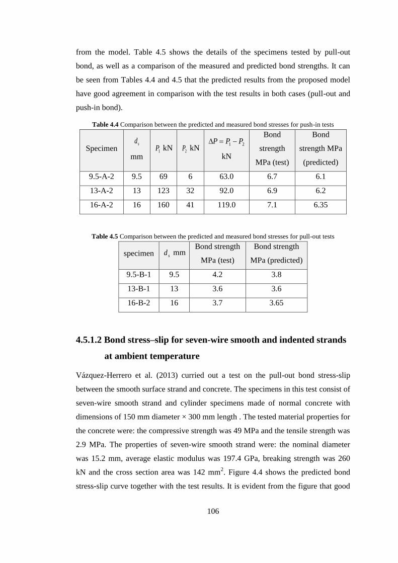
106
from the model. Table 4.5 shows the details of the specimens tested by pull-out
bond, as well as a comparison of the measured and predicted bond strengths. It can
be seen from Tables 4.4 and 4.5 that the predicted results from the proposed model
have good agreement in comparison with the test results in both cases (pull-out and
push-in bond).
Table 4.4 Comparison between the predicted and measured bond stresses for push-in tests
Specimen sd
mm 1P kN 2P kN
21 PPP
kN
Bond
strength
MPa (test)
Bond
strength MPa
(predicted)
9.5-A-2 9.5 69 6 63.0 6.7 6.1
13-A-2 13 123 32 92.0 6.9 6.2
16-A-2 16 160 41 119.0 7.1 6.35
Table 4.5 Comparison between the predicted and measured bond stresses for pull-out tests
specimen sd mm Bond strength
MPa (test)
Bond strength
MPa (predicted)
9.5-B-1 9.5 4.2 3.8
13-B-1 13 3.6 3.6
16-B-2 16 3.7 3.65
4.5.1.2 Bond stress–slip for seven-wire smooth and indented strands
at ambient temperature
Vázquez-Herrero et al. (2013) curried out a test on the pull-out bond stress-slip
between the smooth surface strand and concrete. The specimens in this test consist of
seven-wire smooth strand and cylinder specimens made of normal concrete with
dimensions of 150 mm diameter × 300 mm length . The tested material properties for
the concrete were: the compressive strength was 49 MPa and the tensile strength was
2.9 MPa. The properties of seven-wire smooth strand were: the nominal diameter
was 15.2 mm, average elastic modulus was 197.4 GPa, breaking strength was 260
kN and the cross section area was 142 mm2. Figure 4.4 shows the predicted bond
stress-slip curve together with the test results. It is evident from the figure that good

107
agreement has been achieved between the predicted results from the model and test
results.
Another pull-out test has been adopted in this section to validate the bond model
using seven-wire indented strands. This test was conducted by Lundgren (2002) at
Chalmers University of Technology. The diameter of the strand was 12.9 mm. The
tested concrete compressive strength was 63 MPa and Young’s modulus was
36 GPa. Figure 4.5 shows the comparison between the predicted and tested pull-out
load versus bond slip curves. It can be seen from the figure that the model gives a
good prediction in comparison with test results.
Figure 4.4 Comparison of predicted and tested bond stress–slip curves for the seven-wire smooth
strand at ambient temperature (Vázquez-Herrero et al. 2013)

108
Figure 4.5 Comparison of predicted and tested load–slip curves for the pull-out seven-wire indented
strands at ambient temperature (Lundgren 2002)
4.5.1.3 Bond stress–slip for three-wire indented and smooth strands
at ambient temperature
Gustavson (2004) studied the bond characteristics of three-wire smooth and indented
strands. In this study two types of bond tests were conducted, which were pull-out
and push-in tests. For the push-in test, the indented strand was EU 138/6 with
nominal diameter of 6.5 mm. The strand was prestressed with a force of 28 kN,
corresponding to a prestress of 1320 MPa. The tested concrete compressive strength
was 25 MPa. For the pull-out test, a smooth strand with 6.5 mm diameter and
concrete compressive strength of 55 MPa were used in this test. Figure 4.6 shows the
comparison of predicted and tested load–slip curves for the push-in test. Figure 4.7
illustrates the comparison of predicted and tested load-slip curves for the pull-out
tests. It is clear from the figures that reasonable agreements can be obtained from the
proposed model in comparison with test data in both cases.

109
Figure 4.6 Comparison of predicted and tested load–slip curves for the three-wire push-in test at
ambient temperature (Gustavson 2004)
Figure 4.7 Comparison of predicted and tested load-slip curves for the three-wire pull-out test at
ambient temperature (Gustavson 2004)

110
4.5.1.4 Bond stress–slip curves at elevated temperatures
Moore (2008) studied the bond-slip characteristics of strands at elevated
temperatures. Seven-wire low relaxation strand with grade 270 was used in this
investigation. The diameter of strand was 12.7 mm. Two types of concrete with
different compressive strengths of 77.4 MPa and 98.8 MPa were used in the test. The
dimensions of pull-out specimens were 152.4 x 152.4 x 101.6 mm with embedded
length of 101.6 mm. The specimens were heated with a heating rate of 4.4 oC/min
until the designated temperatures were reached, then held for 60 minutes in the
furnace to obtain a uniform temperature for the specimens, and then the specimens
were left outside the furnace for cooling. Six levels of temperatures were adopted in
this study: 20 oC, 260
oC, 427
oC, 538
oC, 649
oC and 704
oC. In this validation, the
degradation of the bond strength due to high temperatures was used for comparison
between the proposed model and test results by taking ratio of the bond strength at
elevated temperatures over the bond strength at ambient temperature. Figure 4.8 (a)
and Figure 4.8 (b) show the degradation of bond strength versus temperatures using
two values of concrete strength, and compare the predicted results from the proposed
model with the teste results. It is clear from the figures that good results can be
achieved by using the proposed model to predict the bond stress-slip for prestressed
concrete members at elevated temperatures, especially when low concrete
compressive strength is used.

111
Figure 4.8 Comparison of predicted and tested bond strength degradation with different concrete
compressive strengths at elevated temperatures (Moore 2008): (a) 77.4 MPa; (b) 98.8 MPa.
4.5.2 Structural behaviour of prestressed concrete members
Two tests of simply supported PC beams and two tests of simply supported PC slabs
at both ambient and elevated temperatures were used to validate the robustness of
developed model in this section. In all cases of validation, both material and
geometric non-linearity were considered. The predicted results from the VULCAN
program, after incorporating the bond-slip model with it, have been compared with
the experimental results to demonstrate the accuracy of the developed model.
4.5.2.1 Modelling of simply supported PC beams at ambient
temperature
Two different experimental studies on simply supported PC beams have been
adopted to validate the capability of the proposed model to simulate the bond-slip
between the concrete and strands for prestressed concrete beams at ambient
temperature.
The first experimental study was carried out by Cowen and VanHorn (1967). A
prestressed concrete simply supported T-beam Z-1 was used in this study. The
details of the tested beam are shown in Figure 4.9. The strands used in this study

112
were seven-wire 270K strands with diameter of 12.7 mm. These strands were located
in the three layers within the cross-section of the beam, as shown in Figure 4.9.
Figure 4.9 Details of tested T-beam Z-1 (Cowen & VanHorn 1967) (all dimensions in mm)
The strands were initially tensioned to a stress level of 70% of the specified ultimate
stress (which was 1303 MPa) and the average effective prestress force at the time of
the test was 128.5 kN. The concrete compressive strength at the time of the test was
42.4 MPa and the Young’s modulus was 28.9 GPa. By applying the symmetry only
half of the T-beam was modeled. In order to model the PC beam; 5 three-node plain
concrete elements, 25 three-node strands elements and 55 bond-link elements were
employed. By taking the value of 50 ds, the transfer length was 635 mm from the end
of the beam. Therefore, the first 5 bond-link elements were modelled as transfer
bond and the rest of 6 bond-link elements were represented as flexural bond for each
strand, in which the total bond-link elements for five strands involved 25 transfer and
30 flexural bond-link elements. The initial prestressed force was 128.5 kN which can
be applied as initial strain of 0.0055 on the strand’s elements during the structural
analysis. The predicted loads versus mid-span deflection curves are compared
against the tested results as shown in Figure 4.10. It is clear from the figure that there

113
is a good agreement between the results from modelling the PC beam using the
VULCAN program with bond-slip model in comparison with the results from the
test data.
Figure 4.10 Comparison of the predicted and tested load versus mid-span deflections curves for T-
beam Z-1 (Cowen & VanHorn 1967)
The second test was a simply supported T-girder (T-6-1.5h-A) of 8534.4 mm long.
This test was done by Tadros and Morcous (2011) in America Transportation Centre.
The materials used in this test were: Grade 270 low relaxation prestressing seven-
wire strands with diameter of 17.78 mm, six strands were located in two rows with
50.8 mm concrete cover and strand spacing as shown in Figure 4.11. Concrete
compressive strength at the time of the test was 62.0 MPa. Only half of the girder
was modelled due to symmetry. 5 three-node plain concrete elements, 30 three-node
strands elements and 66 bond-link elements were employed for modelling the girder.
The transfer length was 889 mm from the end of the beam, thus 36 bond-link
elements were modelled as transfer bond and the rest of 30 bond-link elements were
represented the flexural bond. The initial prestress strain of 0.003 was applied on the
strand’s elements. Figure 4.12 shows the loads versus mid-span deflection curves for
the test results from the experiment and compare that with the predicted results from
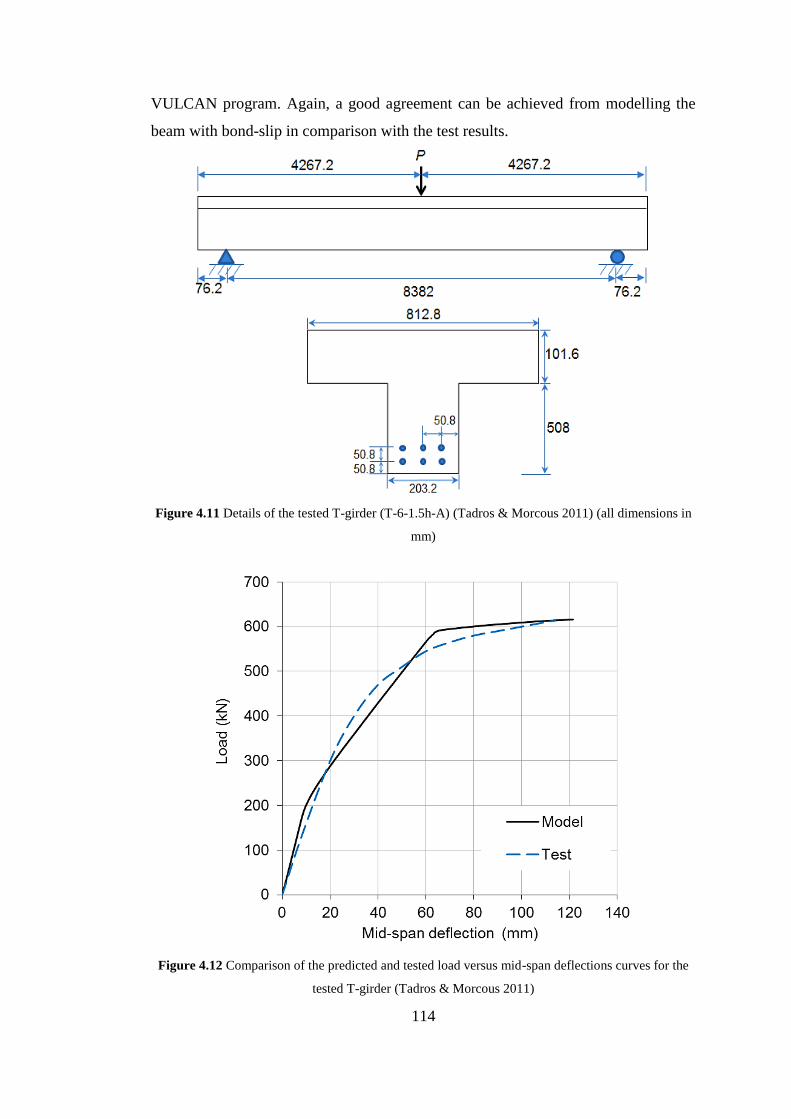
114
VULCAN program. Again, a good agreement can be achieved from modelling the
beam with bond-slip in comparison with the test results.
Figure 4.11 Details of the tested T-girder (T-6-1.5h-A) (Tadros & Morcous 2011) (all dimensions in
mm)
Figure 4.12 Comparison of the predicted and tested load versus mid-span deflections curves for the
tested T-girder (Tadros & Morcous 2011)

115
4.5.2.2 Modelling fire tests of simply supported PC slabs
Two slabs have been adopted to validate the robustness and accuracy of the current
model at elevated temperatures. The first slab was simply supported PC slab TB3
tested by Bailey and Ellobody (2009). The length of the slab was 4.0 m with 1.6 m
width and thickness of 16 cm. Figure 4.13 illustrates the details of TB3 slab. The
tested slab was subjected to the standard time-temperature curve specified in BS
EN1991-1-2 (CEN 2002) by using gas furnace. The slab was heated over a middle
length of 3.2 m out of its 4.0 m as shown in Figure 4.13. The tested concrete
compressive strength at the time of test was 36.6 MPa. The strand was 15.7 mm
seven-wire smooth strand of grad 270 with yield stress of 1675 MPa. These tested
material properties were used as an input data for the modelling. Due to the
symmetry of the slab, only half of the slab was modelled.
Figure 4.13 Details of PC Slab TB3 (Bailey & Ellobody 2009) (all dimensions in mm)
Two steps were followed for modelling the tested slab. In the first step, thermal
analysis was performed by dividing the cross section of the slab into segments in
order to predict the temperatures distribution within the cross-section of the slab.
During the test, there was no evidence of concrete spalling on the heated surface;
therefore, the spalling has not been considered in the thermal and structural analysis.

116
The predicted and tested temperature histories throughout the cross section of the
slab at mid-span are shown in Figure 4.14; in which T represents the strands
temperatures, HS refers to the hot bottom surface, MS for mid-height of the slab and
CS represents the cold top surface of the slab. The predicted temperature histories of
the strands and concretes from the thermal analysis were used as temperature input
data for the structural analysis.
Figure 4.14 Comparison between the predicted and tested temperature histories (Bailey & Ellobody
2009)
Structural analysis was performed for the slab in the second step. The slab TB3 was
modelled using 5 three-node plain concrete elements, 15 three-node strand elements
and 33 bond-link elements. The transfer length of 50 ds was 785 mm from the end of
the slab, hence 9 bond-link elements were modelled as transfer bond and the rest of
24 bond-link elements were represented as flexural bond. In the structural modelling
the reference axis was assumed to coincide with the central axis of plain concrete
elements. In order to take into account the effect of strands curvature within the
prestress system, the real positions of the strand elements within the cross-section of
the slab and along the slab length were considered by offset the elements nodes
based on the reference axis. The average applied design prestress force in the three

117
strands after pre-tension was 169 kN. This force can be modelled as an initial strain
of 0.0045 to the strands elements to simulate the prestress on the strands. Same
segmentation of the cross section of the slab that used in the thermal analysis was
adopted for the structural analysis. The total vertical load of 41.6 kN (which
represents 60% of the load capacity) was applied to the slab. This static load was
kept constant during fire test.
Figure 4.15 shows the comparison of the predicted and measured mid-span
deflections of the Slab TB3. The predicted and tested longitudinal expansions of the
slab TB3 are shown in Figure 4.16. It is evident that the predictions using the current
model agreed reasonably well with the test results.
Figure 4.15 Comparison of predicted and measured mid-span deflections of Slab TB3 (Bailey &
Ellobody 2009)
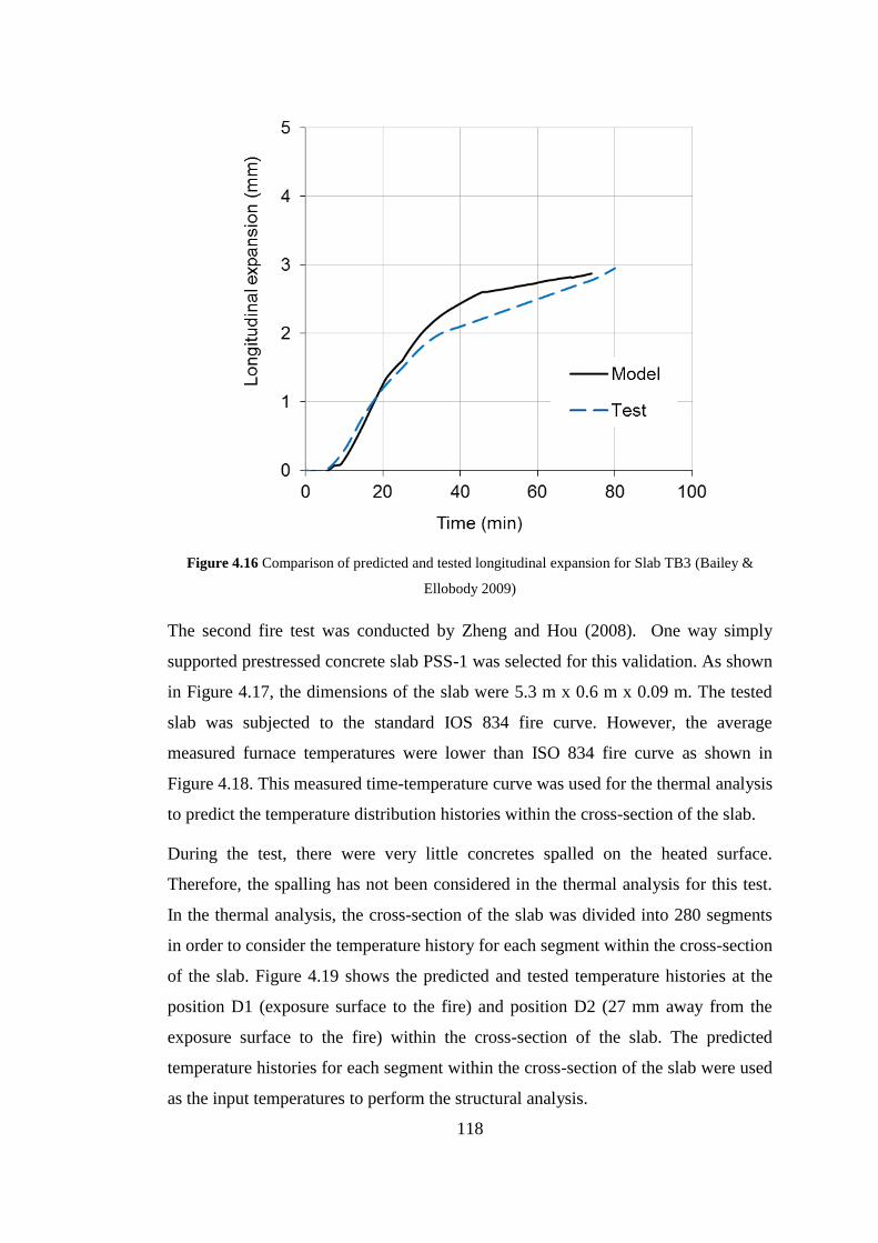
118
Figure 4.16 Comparison of predicted and tested longitudinal expansion for Slab TB3 (Bailey &
Ellobody 2009)
The second fire test was conducted by Zheng and Hou (2008). One way simply
supported prestressed concrete slab PSS-1 was selected for this validation. As shown
in Figure 4.17, the dimensions of the slab were 5.3 m x 0.6 m x 0.09 m. The tested
slab was subjected to the standard IOS 834 fire curve. However, the average
measured furnace temperatures were lower than ISO 834 fire curve as shown in
Figure 4.18. This measured time-temperature curve was used for the thermal analysis
to predict the temperature distribution histories within the cross-section of the slab.
During the test, there were very little concretes spalled on the heated surface.
Therefore, the spalling has not been considered in the thermal analysis for this test.
In the thermal analysis, the cross-section of the slab was divided into 280 segments
in order to consider the temperature history for each segment within the cross-section
of the slab. Figure 4.19 shows the predicted and tested temperature histories at the
position D1 (exposure surface to the fire) and position D2 (27 mm away from the
exposure surface to the fire) within the cross-section of the slab. The predicted
temperature histories for each segment within the cross-section of the slab were used
as the input temperatures to perform the structural analysis.
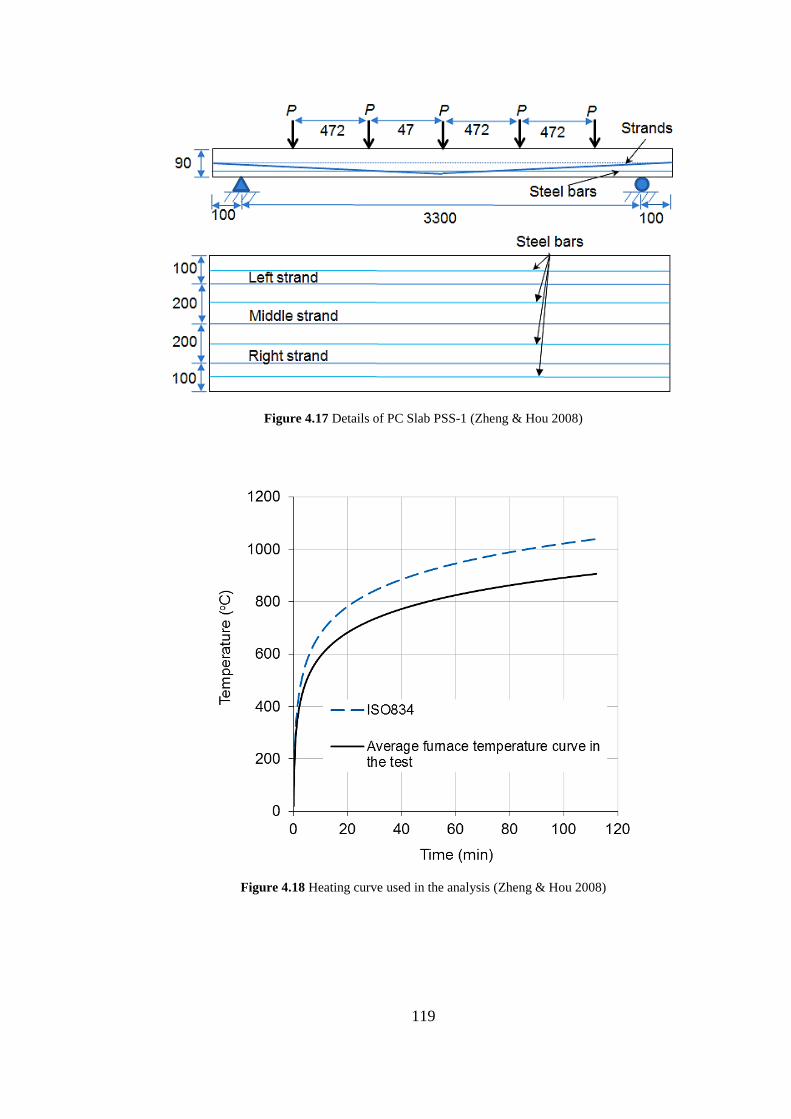
119
Figure 4.17 Details of PC Slab PSS-1 (Zheng & Hou 2008)
Figure 4.18 Heating curve used in the analysis (Zheng & Hou 2008)

120
Figure 4.19 The predicted and tested temperature histories for Slab PSS-1 (Zheng & Hou 2008)
The tested concrete compressive strength at the time of test was 32.0 MPa, the strand
was 5.0 mm seven-wire smooth strand with yield strength of 1498 MPa. The
additional reinforcing steel bars were 6.5 mm with yield strength of 328 MPa, and
8.0 mm with yield strength of 320 MPa. Those tested material were used as the input
data for modelling the slab.
For structural analysis, the slab PSS-1 was modelled using 8 three-node plain
concrete elements, 24 three-node strands elements and 51 bond-link elements. The
transfer length was 250 mm at both ends of the slab; hence 18 bond-link elements
were modelled as transfer bond at each end of the slab and the rest of 33 bond-link
elements were represented as flexural bond within the middle of the slab. Again the
reference axis was assumed to coincide with the central axis of the plain concrete
elements. The real positions of the strand elements within the cross-section of the
slab and along the slab length were considered in the modelling to simulate the
strand’s curvature by offset the strands elements based on the reference axis. The
prestress force in the strand for pre-tension was 70.7 kN. This force was applied as
initial strain of 0.0046 to the strands elements to simulate the prestress on the strands
in the model. The segmentations of the cross sections for the plain concrete elements

121
were the same as the thermal analysis. The applied load was five concentrated load
of 1.53 kN (including the self-weight of the slab), which represents 0.35 of the load
capacity of the slab. This static load was kept constant during the fire test. Figure
4.20 shows the comparison between the predicted and measured mid-span
deflections of the slab PSS-1. It is clear from the figure that the predictions results
from VULCAN software (after incorporating the current model) agree well with the
test results.
Figure 4.20 Comparison of predicted and measured mid-span deflections of Slab PSS-1 (Zheng &
Hou 2008)
To summarise the validation in this section, two large scale PC beams at ambient
temperature and two large scale PC slabs under fire conditions, which conducted by
different researchers, were modelled to validate the model developed in this project.
It is important to mention that the influence of bond stress-slip on PC structural
members at ambient temperature is not significant due to high interaction between
the concrete and strands. Hence, it is reasonable to assume the full interaction
between concrete and steel strand for modelling PC members at ambient
temperature. However, the effect of the bond at elevated temperatures is significant
because of the degradation of bond stress due to high temperatures. As shown in
122
Figure 4.8, when the temperature is higher than 450oC, the bond strength reduces to
60% of the original strength at ambient temperature. Hence, for fire resistance design
of PC structural member it is unconservative to assume fully bounded between
concrete and steel strand as the bond can control the failure of PC members. Finally,
It is evident from this study that the proposed bond-slip model can be used with
reasonable accuracy for modelling the structural behaviour of PC members at both
ambient and elevated temperatures.
4.6 Conclusions
In this chapter, a new analytical model has been developed to predict the bond stress-
slip between strands and concrete for prestressed concrete members under fire
conditions. The model is based on the mechanical interlocking between the
prestressing steel strands and surrounding concrete as well as the effect of Poisson’s
ratio (Hoyer effect). The model takes into account the variation of the concrete
properties and strands’ geometries, as well as effect of the cohesion and friction
between the strands and concrete. The degradation of the bond strength at elevated
temperatures is related to the concrete material properties changed with temperature.
The developed bond stress-slip model has been incorporated into the VULCAN
software by using two-node bond-link element approach for analysing the structural
behaviours of prestressed concrete structural members in fire. Series of validations
have been conducted using the previous tested data generated by different
researchers. Reasonable agreements have been achieved between the predicted
results from the model in comparison with the tests results. The model presented in
this chapter is able to predict the bond-slip characteristic between the concrete and
strands for three-wire and seven-wire strands at both ambient and elevated
temperatures. This model can be used to calculate the bond-slip for the transfer
length (push-in bond) and flexural length (pull-out bond) within the prestressed
concrete members. Also, the model is able to take into account different strand’s
diameters and different strand’s surfaces (smooth or indented).

123
Chapter 5 Parametric study on the bond behaviour
at elevated temperatures
As presented in Chapter 3, a new model for modelling the bond stress-slip between
concrete and steel reinforcing bars at elevated temperatures has been developed. In
order to understand the bond behaviour under different conditions, this chapter will
dedicate to study the factors that can influence on the bond stress-slip under fire
conditions. These factors are: influence of yielding the steel bars, effect of the
concrete cover, influences of the concrete compressive strength and concrete
spalling.
5.1 Introduction
Understanding the response of reinforced concrete members during loading is
essential to design an efficient and safe structure. Experimental tests are commonly
conducted to study the behaviour of an individual member under various factors.
This method can provide actual behaviour of the structural members, however it is
time consuming and expensive, especially for members subjected to fire conditions.
Also, behaviour of individual member subjected to standard fire curve does not
represent the real behaviour of building under fire condition, which makes it difficult
for the designer to determine the appropriate level of safety for the structures.
Recently, finite element analysis is an alternative method that can be used to analyse
the structural members or even whole building in fire. Finite element analysis
provides an accurate prediction on the response of the structural elements that have
different parameters, such as materials properties, element geometry, temperature
and different types of loading. Elements geometry may change during loading in
slender members like columns or for large deformable members. Therefore, non-
linear analysis is a procedure that can be used to stimulate the inelastic behaviour of
the elements (material and geometry) under different loading conditions (Badiger &
Malipatil 2014).
Generally, researchers indicated that reinforced concrete structures have good fire
resistance, better than steel structures. This assumption is correct if the cross-sections
of the concrete members retain their integrity. However, spalling of concrete cover

124
causes severe damage to the reinforced concrete elements due to exposing steel bars
directly to the fire (Bailey 2002).
At present, numerous models have been developed to study the behaviour of
reinforced concrete members at ambient and elevated temperatures. But, the majority
of these models were based on the assumption of full interaction between concrete
and reinforcing bars (Huang 2010). However, the results presented in Chapter 3 and
Chapter 4 indicated that the assumption of full bond between concrete and rebar at
elevated temperatures is unconservative. The behaviour of the bond between
concrete and steel bars has a considerable influence on the fire resistance of
reinforced concrete members. Hence, the main objectives of this chapter are to:
Conduct a parametric study to investigate the influence of the bond stress-
slip on the response of reinforced concrete beam and slab members under
fire conditions.
Study the factors that effects on the bond stress-slip behaviour. These factors
are: reinforcing steel bars’ yielding; the thickness of concrete cover, concrete
compressive strength and concrete spalling.
Study the behaviours of different structural members within a whole
building under different fire compartment conditions.
5.2 Modelling background
The behaviour of reinforced concrete structures under fire condition has been
investigated by Huang (2010). The Finite element program VULCAN was used to
simulate a reinforced concrete frame in fire. This frame (as shown in Figure 5.1) has
been adopted in this research to perform the studies of the bond behaviour between
concrete and reinforcement under fire conditions. As shown in Figure 5.2, the
reinforced concrete structure is modelled as an assembly of finite plain beam–
column and slab elements, reinforcing steel bar elements and bond-link elements.
Each node from these elements is defined in a common reference plane. This
reference plane is assumed to coincide with the mid-surface of the slab elements and
its location is fixed throughout the analysis. Both materials and geometric non-
linearity are taken into account in this model. The sophisticated behaviours of the
structures under elevated temperatures such as thermal expansion, degradation of

125
stress–strain curves, failure of concrete segments due to cracking and crushing of
concrete, failure of steel reinforcement by yielding or bar’s rupture are all considered
in this model (Huang et al. 1996; Huang et al. 1999; Huang et al. 2009; Huang
2010).
Figure 5.1 Whole floor layout of reinforced concrete structure
Analysis of the reinforced concrete members involves two phases: the first phase is
to carry out the thermal analysis on the beam or slab. This thermal analysis can be
achieved using two-dimensional non-linear finite-element computer program
developed by Huang et al. (1996). In this program the thermal properties for concrete
and steel given in Eurocode 2 (CEN, 2004a) are adopted. The second phase of the
analysis is to perform structural analysis for the beam or slab members using
VULCAN software. The output data from the thermal analysis are used as the
temperature input data for the structural analysis.
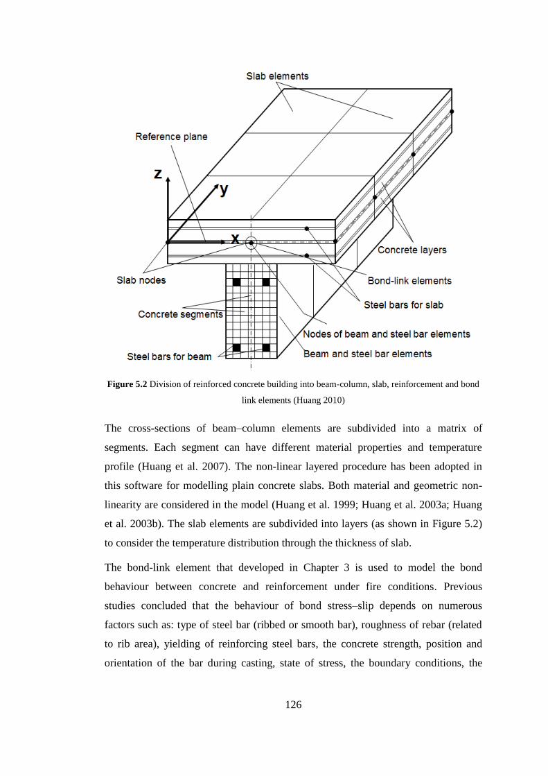
126
Figure 5.2 Division of reinforced concrete building into beam-column, slab, reinforcement and bond
link elements (Huang 2010)
The cross-sections of beam–column elements are subdivided into a matrix of
segments. Each segment can have different material properties and temperature
profile (Huang et al. 2007). The non-linear layered procedure has been adopted in
this software for modelling plain concrete slabs. Both material and geometric non-
linearity are considered in the model (Huang et al. 1999; Huang et al. 2003a; Huang
et al. 2003b). The slab elements are subdivided into layers (as shown in Figure 5.2)
to consider the temperature distribution through the thickness of slab.
The bond-link element that developed in Chapter 3 is used to model the bond
behaviour between concrete and reinforcement under fire conditions. Previous
studies concluded that the behaviour of bond stress–slip depends on numerous
factors such as: type of steel bar (ribbed or smooth bar), roughness of rebar (related
to rib area), yielding of reinforcing steel bars, the concrete strength, position and
orientation of the bar during casting, state of stress, the boundary conditions, the

127
concrete cover (CEB-FIP Model code 90 1991; CEB-FIP-Bulletin10 2000; CEB-FIP
2010; Huanzi 2009). Those factors are considered in this research.
Influence of concrete spalling on the thermal and structural behaviour of reinforced
concrete members is also considered in this investigation. The effect of concrete
spalling is represented by using void segments within the cross-section of beam and
column, and void layers within the cross-section of slab. It is assumed that the void
segments and void layers have zero mechanical strength, stiffness and thermal
resistance. After spalling the outer parts from the concrete, the inner-parts will
expose directly to the fire. In which the fire boundary moves within the cross-section
of the concrete member. When the spalling reaches to the steel reinforcement, the
bond strength will becomes zero in this region. A critical temperature is used as a
criterion for the concrete spalling, in which the segment or the layer will be spalled
when the temperature of this segment or layer reaches the ‘critical temperature’. The
spalling of concrete is assumed not to reach a point beyond the reinforcing cage of
the member.
As shown in Figure 5.1, it is assumed that the building contains of ten floors with 4.5
m height of each story. Dimensions of each floor are 37.5 m x 37.5 m with five 7.5
m x 7.5 m bays in each direction. The building is subjected to ISO 834 standard fire
(ISO-834 1975). The building represents a commercial office building and designed
based on Eurocode 2 (CEN 2004a; CEN 2004b). The self-weight is 7.5 kN/m2 for
concrete density of 24 kN/m3. Raised floor involves: 0.5 kN/m
2 for ceiling, 0.5
kN/m2 for services and 1.0 kN/m
2 for partitions with impose load of 2.5 kN/m
2. The
total design load on the slab is 10.75 kN/m2 at the fire limit state. The concrete
compressive strength is 45 MPa with moisture content of 4% by weight and the yield
strength of steel bar is 460 MPa. It is assumed that the building required two hours
fire resistance with the slab cover of 25 mm. The floor slab thickness is 250 mm
based on Eurocode 2 (CEN 2004b). The length of the beam is 7.5 m and exposed to
fire from three sides as illustrated in Figure 5.3 and Figure 5.7. The cross-section’s
details of the beams are shown in Figure 5.4, which have dimensions of 500 x 350
mm and concrete cover of 30 mm.
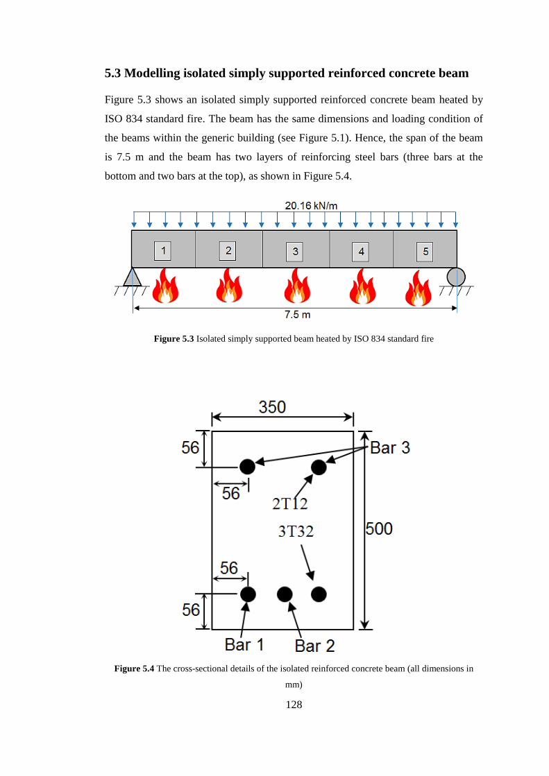
128
5.3 Modelling isolated simply supported reinforced concrete beam
Figure 5.3 shows an isolated simply supported reinforced concrete beam heated by
ISO 834 standard fire. The beam has the same dimensions and loading condition of
the beams within the generic building (see Figure 5.1). Hence, the span of the beam
is 7.5 m and the beam has two layers of reinforcing steel bars (three bars at the
bottom and two bars at the top), as shown in Figure 5.4.
Figure 5.3 Isolated simply supported beam heated by ISO 834 standard fire
Figure 5.4 The cross-sectional details of the isolated reinforced concrete beam (all dimensions in
mm)

129
As mentioned before, two steps should be followed in order to analyse the beam
under fire condition. Firstly, the thermal analysis of the beam was conducted to
calculate the temperature history within the cross-section of the beam. In this step,
the cross-section of the beam was divided into 441 segments (21 x 21). Same
segmentations were used within the cross-section of the beam for the structural
analysis.
Spalling of the concrete was taken into account in this investigation to study the
influence of spalling on the thermal and structural behaviours of the beam. Previous
research indicated that the spalling of concrete is very likely to occur within the first
30 minutes of ISO 834 fire test and the range of the critical spalling temperature of
concrete is between 200 oC to 400
oC (Huang 2010). Hence, the critical spalling
temperature of concrete in this study is assumed to be 350oC. For assessing the
influence of the bond on the behaviour of the beam, the beam with both of full or
partial bond conditions between the concrete and reinforcement were modelled.
As mentioned before, the bond-stress slip relationship are affected by numerous
factors such as steel bar roughness, thickness of concrete cover, concrete strength,
position and orientation of steel bar during casting, boundary conditions, state of
stress and yielding of reinforcing steel bars (CEB-FIP Model code 90, 1991; CEB-
FIP-Bulletin10 2000). Hence, the factors considered for investigation here are:
yielding of reinforcing steel bars, the concrete cover, the concrete compressive
strength and concrete spalling.
Details of the reinforced concrete beam were given in Figures 5.3 and 5.4. The
uniform line load acting on the beam was 20.16 kN/m, which is the same as the
beam within the frame shown in Figure 5.1. The concrete compressive strength was
45 MPa and the yield stress of the steel bar was 460 MPa. The beam was modelled
as an assembly of 5 three-node plain concrete beam elements and 25 three-node
reinforced steel elements and 55 two-node bond link elements. Using the bond-link
elements the beam can be modelled with full, partial or even zero interaction
between concrete and reinforcing steel bars.

130
5.3.1 Yielding effect of reinforcing steel bars on the bond behaviour
The proposed model presented in Chapter 3 has been further improved in this
chapter to take into account the yielding effect of steel bar on the bond behaviour.
Yielding of the steel bar within the plastic range has an effect on the bond strength
similar to the effect of splitting of concrete cover. A reduction in the steel bar
diameter can occur due to steel bar’s yielding. This contraction leads to a great
reduction in the friction between concrete and rebar, and also affects the geometry of
the bar ribs, which consequently reduces the bond stress (CEB-FIP-Bulletin10
2000).
In order to consider the yielding effect of steel bar on the bond behaviour, the bond
stress should be modified by the factor y as follow (CEB-FIP 2010):
y .modified (5.1)
sysy for 0.1 (5.2)
sussy
a
y foreb
51.85.00.1 (5.3)
In which:
sysu
sysa
(5.4)
2
2
y
t
f
fb (5.5)
Where: s is the steel strain; sy is the yield strain of steel bar at the yield stress yf ;
su is the ultimate steel strain, tf is the steel stress and yf is the yield stress of the
steel bar. The yielding effect of the steel bar on the bond stress-slip curve is shown in
Figure 5.5. This effect has been incorporated into the bond model developed in
Chapter 3.

131
For demonstrating the influence of the yielding effect of reinforcing steel bar on the
bond behaviour, the isolated beam was modelled using the bond models with and
without the yielding effect of reinforcing steel bar. In the modelling, the concrete
compressive strength was 45 MPa, the steel strength was 460 MPa and the concrete
cover was 30 mm.
Figure 5.5 Influence of steel strains on local bond-stress slip relationship (CEB-FIP 2010)

132
Figure 5.6 Yielding effect of reinforcing steel bar on the bond behaviour
Figure 5.6 shows the influence of yielding the steel bar on the central deflection of
the beam under ISO 834 fire, together with the central deflection of the beam
modelled with full bond interaction. As shown in Figure 5.6, the yielding effect of
the steel bar has some degrees of influence on the bond behaviour but the influence
is not significant. However, this demonstrated that the yielding effect of steel bar can
reduce the bond strength between concrete and the steel bar.
5.3.2 The effect of concrete cover on the bond behaviour
Concrete cover is an important part for reinforced concrete members. Concrete cover
provides the protection for the reinforcing steel bars from the outside attacks such as
chloride, which can result corrosion for the steel bars. Also, the concrete cover gives
isolation for the reinforcement from the high temperatures under fire conditions.
Moreover, concrete cover provides the confinement for the steel bars to generate the
bond between concrete and reinforcement.
Same isolated beam with concrete compressive strength of 45 MPa and steel strength
of 460 MPa was used in this investigation. In order to investigate the sensitivity of
the bond-slip model to the concrete cover of the beam at elevated temperatures, five

133
values of concrete cover thicknesses (10, 20, 30, 40 and 50 mm) were adopted in this
study. The cross-section of the beam was subdivided into segments of concrete and
steel, as shown in Figure 5.7. The same segmentation was used for both thermal and
structural modelling of the beam. Also the beam was heated from three sides (see
Figure 5.7).
Figures 5.8 to 5.10 show the temperatures of the reinforcing steel bars within the
cross-section of the beam (Bar 1, Bar 2 and Bar 3 as identified in Figure 5.4) with
different thickness of concrete covers. It is clear from the figures that the temperature
of the steel bars decreases by increasing the concrete cover of the beam. Hence, the
concrete cover can provide the protection to the reinforcing steel bars from the fire
and reduce the effect of temperature on the steel bars and bond strength within the
cross-section of reinforced concrete beams. It can be seen from the figures that after
two hours (120 min) of exposing to ISO 834 standard time-temperature, the
temperature for Bar-1 with cover 50 mm is less than that for cover 10 mm by about
47%, while for Bar-2 the temperature reduced by 49% and for Bar-3 the temperature
reduced by 56%.
Figure 5.7 Segmentation of the beam cross-section

134
Figure 5.8 Temperature histories of the steel bar (Bar 1) for the beam subjected to ISO 834 standard
fire with different thicknesses of concrete cover
Figure 5.9 Temperature histories of the steel bar (Bar 2) for the beam subjected to ISO 834 standard
fire with different thicknesses of concrete cover

135
Figure 5.10 Temperature histories of the steel bar (Bar 3) for the beam subjected to ISO 834 standard
fire with different thicknesses of concrete cover
Influence of concrete cover on the bond behaviour at elevated temperatures is
presented based on the response of the beam to the high temperatures. Generally,
degradation of the bond strength results in extra central deflection of the beam due to
the bond deterioration. Figures 5.11 to 5.15 give comparisons between the case of
full bond (full interaction between the concrete and reinforcement) and partial bond-
slip between the concrete and steel bars for each thickness of concrete cover at
elevated temperatures.
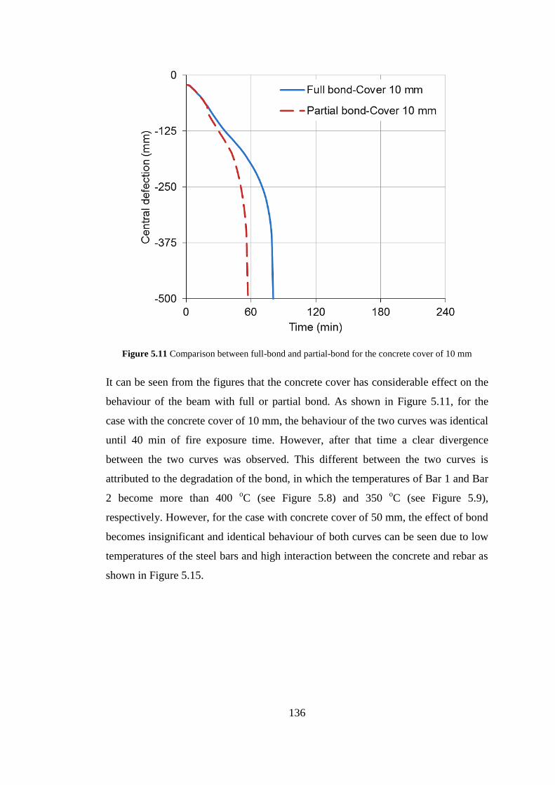
136
Figure 5.11 Comparison between full-bond and partial-bond for the concrete cover of 10 mm
It can be seen from the figures that the concrete cover has considerable effect on the
behaviour of the beam with full or partial bond. As shown in Figure 5.11, for the
case with the concrete cover of 10 mm, the behaviour of the two curves was identical
until 40 min of fire exposure time. However, after that time a clear divergence
between the two curves was observed. This different between the two curves is
attributed to the degradation of the bond, in which the temperatures of Bar 1 and Bar
2 become more than 400 oC (see Figure 5.8) and 350
oC (see Figure 5.9),
respectively. However, for the case with concrete cover of 50 mm, the effect of bond
becomes insignificant and identical behaviour of both curves can be seen due to low
temperatures of the steel bars and high interaction between the concrete and rebar as
shown in Figure 5.15.
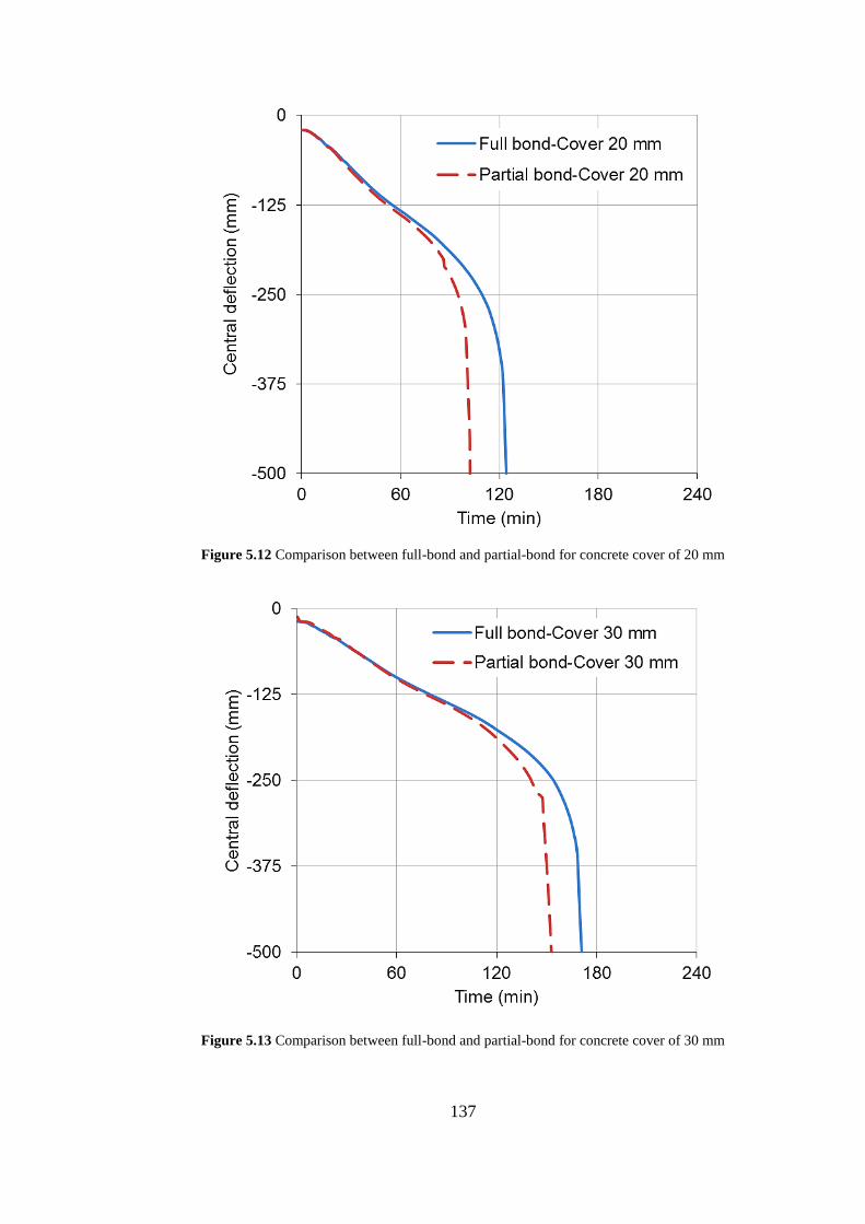
137
Figure 5.12 Comparison between full-bond and partial-bond for concrete cover of 20 mm
Figure 5.13 Comparison between full-bond and partial-bond for concrete cover of 30 mm

138
Figure 5.14 Comparison between full-bond and partial-bond for concrete cover of 40 mm
Figure 5.15 Comparison between full-bond and partial-bond for concrete cover of 50 mm

139
It can be concluded from the Figures 5.11 to 5.15 that, increasing the thickness of
concrete cover has a great influence on the bond-slip, in which the degradation of the
bond strength decreases with increasing the thickness of concrete cover. As
mentioned before, the concrete cover is the main factor that can provide the
protection to the steel bars and gives the confinement to the reinforcement for the
bond strength. Therefore, the designer should carefully choose the proper concrete
cover.
Finally, it is important to explain the type of failure based on the outputs of the
VULCAN software. The failure of the beam with the concrete cover of 50 mm
occurred mainly due to concrete cracking. For concrete covers of 40 mm, 30 mm and
20 mm the failure of the beam occurred due to concrete cracking, yielding the steel
bars as well as the bond failure of some elements. For concrete cover of 10 mm the
failure of the beam firstly occurred due to concrete cracking, then yielding the steel
bars followed by rupture of some steel bars, also the failure of the most bond-link
elements between the reinforcement and concrete.
The results generated from this study further support the claims of previous
researchers that the concrete cover has a great influence on the bond strength by
providing the confinement to the reinforcement. Hence, reduce the concrete cover is
not only leads to increase the temperature of the reinforcement during fire, but also
decreases the concrete confinement which can play a significant factor on the bond
strength (CEB-FIP-Bulletin10 2000).
Figure 5.16 shows the influence of different concrete covers on the behaviour of the
beam modelled with partial bond. It is evident that the concrete cover has a great
influence on the behaviour of the beam. By considering the deflection criterion
(span/20), the fire resistance for the beam is 77 min, 120 min, 167 min and 217 min
for the concrete of 10 mm, 20 mm, 30 mm, 40 mm respectively. And more than four
hours (240 min) fire resistance can be achieved when the concrete cover is 50 mm.
Hence, increasing the concrete cover from 10 mm to 40 mm can increase the fire
resistance of the beam for more than two hours.

140
Figure 5.16 Influence of concrete cover on the structural behaviour of a simply supported beam
modelled with partial bond
5.3.3 The effect of concrete spalling on the behaviour of the beam
Spalling of concrete in fire has a significant effect on the steel bars and the bond
strength, which influence on the behaviour of reinforced concrete members. When
the spalling of concrete occurs, the members will lose the concrete cover and the
reinforcement will be exposed directly to the fire. Then, a great reduction in the
strength and stiffness of steel bars can occur. Also, failure of the bond between the
concrete and the rebar can happen due to losing the confinement of the concrete to
the steel bar. The influence of spalling on a reinforced concrete beam was
investigated by Huang (2010). The results from the study indicated that the influence
of spalling for full-bonded member is significant, especially when the spalling occurs
within the mid-span elements.
In this study the effect of concrete spalling on the bond behaviour was considered by
modelling the beam using partial bond model. Same isolated beam has been used for
this investigation. The beam has concrete compressive strength of 45 MPa, the steel
bar yielding of 460 MPa and concrete cover of 40 mm. As shown in Figure 5.3, the

141
beam was modelled as an assembly of five plain concrete beam elements, 25 steel
bar elements and 55 bond-link elements. In order to consider the effect of concrete
spalling, void segments were used to represent the spalled concrete for the thermal
and structural analysis. In this study, both full and partial bond were considered to
investigate the effect of spalling on the behaviour of the beam. The time-temperature
histories of the reinforcing steel bars for the cases of concrete spalling and no-
spalling are illustrated in Figure 5.17. It is clear from the figure that the spalling of
concrete cover has a great influence on the thermal behaviour of the beam. For
instant, Bar 1 reached to temperature about 500 oC after 120 min with no-spalling of
concrete, but with spalling Bar 1 reached to this temperature after just 24 min.
Figure 5.17 Temperature histories of the reinforcing bars for the beam exposed to ISO 834 standard
fire
Figure 5.18 shows the influence of concrete spalling on the behaviour of the beam
modelled as full or partial bond. It was assumed that all elements were subjected to
concrete spalling. It can be seen that the impact of concrete spalling on the beam is
very significant for both full bond and partial bond cases. However, the effect of
spalling on the beam modelled with partial bond is greater than that modelled with
full bond. Figures 5.19 to 5.22 give comparisons for the behaviour of the beam
subjected to different concrete spalling and bond conditions.

142
Figure 5.18 Influence of concrete spalling on the behaviour of the beam modelled as full or partial
bond
Figure 5.19 shows the comparison of the behaviour of the beam modelled as full
bond or partial bond in which all elements were spalled. It is clear from the figure
that a big different can be seen between full bond and partial bond cases. From
Figures 5.20 to 5.22, it is evident that the effect of spalling becomes more significant
when elements 1&5 were spalled (see Figure 5.3 for element’s positions) than the
other elements. This can be justified as the bond stress at the end elements of the
beam is higher than the bond stress at the middle elements, hence weaken the bond at
the end elements has more influence on the response of the beam. It was observed
from the VULCAN output files that the failure of the beam, when elements 1&5
were spalled, occurred due to bond failure and even bar rupture. While for other
cases, the failure of the beam was dominated by yielding the steel bars.

143
Figure 5.19 Comparison of the behaviour of the beam modelled as full bond or partial bond (all
elements spalled)
Figure 5.20 Comparison of the behaviour of the beam modelled as full bond or partial bond
(elements 1&5 spalled)

144
Figure 5.21 Comparison of the behaviour of the beam modelled as full bond or partial bond
(elements 2&4 spalled)
Figure 5.22 Comparison of the behaviour of the beam modelled as full bond or partial bond (element
3 spalled)

145
5.3.4 The effect of concrete strength on the bond
Concrete compressive strength is one of the factors that effect on the bond strength.
The maximum bond strength max is related to concrete compressive strength as:
ckfamax (5.6)
where: ckf is the concrete compressive strength and a is a constant based on the
bond characteristic (CEB-FIP Model code 90 1991; CEB-FIP 2010). Bond stress is a
result from the shear strength of the concrete in front of steel bar ribs and the
circumference tensile stress of the concrete surround the rebar. Therefore,
degradation of the bond at elevated temperatures is directly linked to the concrete
deterioration.
Figure 5.23 Time-temperature histories for the reinforcing steel bars of the beam subjected to IOS
834 standard fire
Same isolated beam with concrete cover of 40 mm and steel bar yielding strength of
460 MPa was used in this section to study the effect of concrete compressive
strength on the bond behaviour. A range of concrete compressive strengths (20, 30,
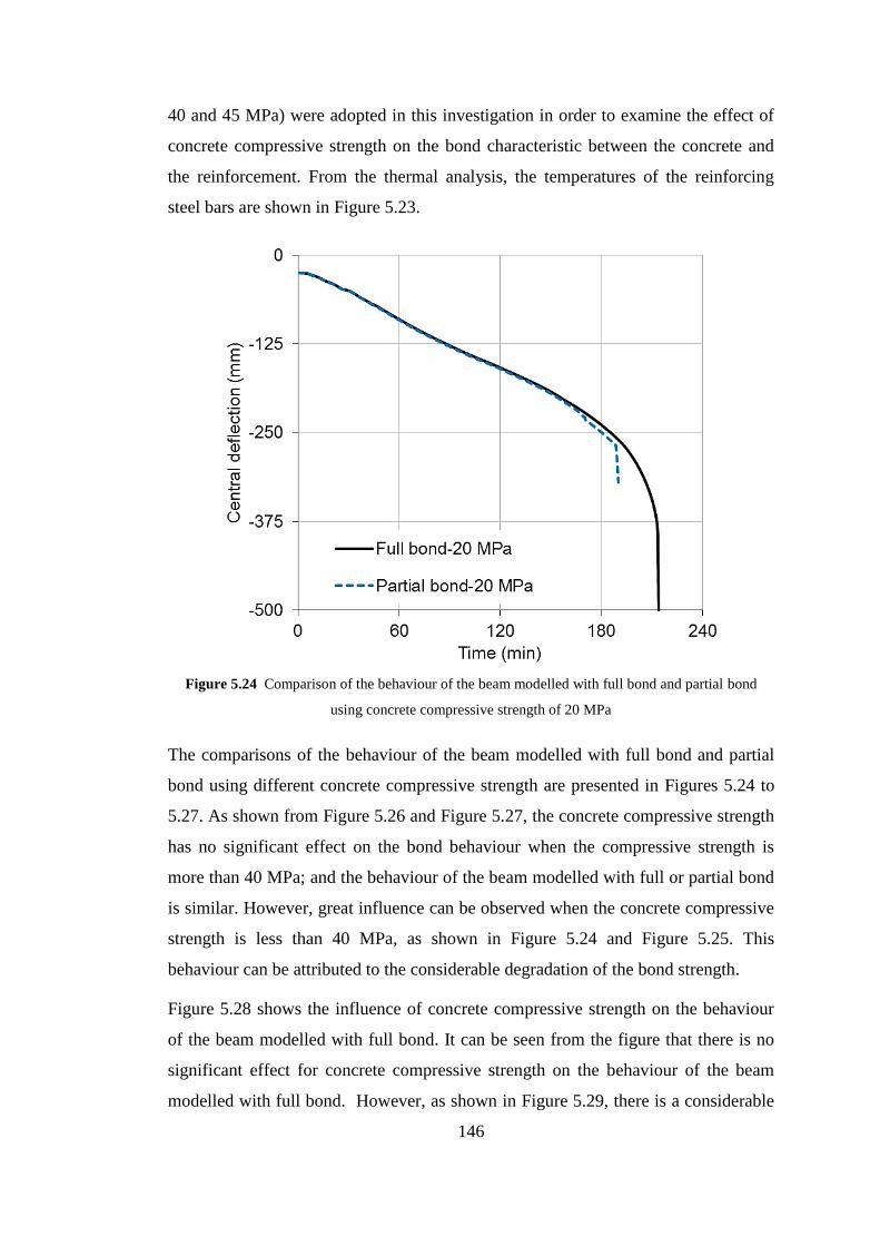
146
40 and 45 MPa) were adopted in this investigation in order to examine the effect of
concrete compressive strength on the bond characteristic between the concrete and
the reinforcement. From the thermal analysis, the temperatures of the reinforcing
steel bars are shown in Figure 5.23.
Figure 5.24 Comparison of the behaviour of the beam modelled with full bond and partial bond
using concrete compressive strength of 20 MPa
The comparisons of the behaviour of the beam modelled with full bond and partial
bond using different concrete compressive strength are presented in Figures 5.24 to
5.27. As shown from Figure 5.26 and Figure 5.27, the concrete compressive strength
has no significant effect on the bond behaviour when the compressive strength is
more than 40 MPa; and the behaviour of the beam modelled with full or partial bond
is similar. However, great influence can be observed when the concrete compressive
strength is less than 40 MPa, as shown in Figure 5.24 and Figure 5.25. This
behaviour can be attributed to the considerable degradation of the bond strength.
Figure 5.28 shows the influence of concrete compressive strength on the behaviour
of the beam modelled with full bond. It can be seen from the figure that there is no
significant effect for concrete compressive strength on the behaviour of the beam
modelled with full bond. However, as shown in Figure 5.29, there is a considerable
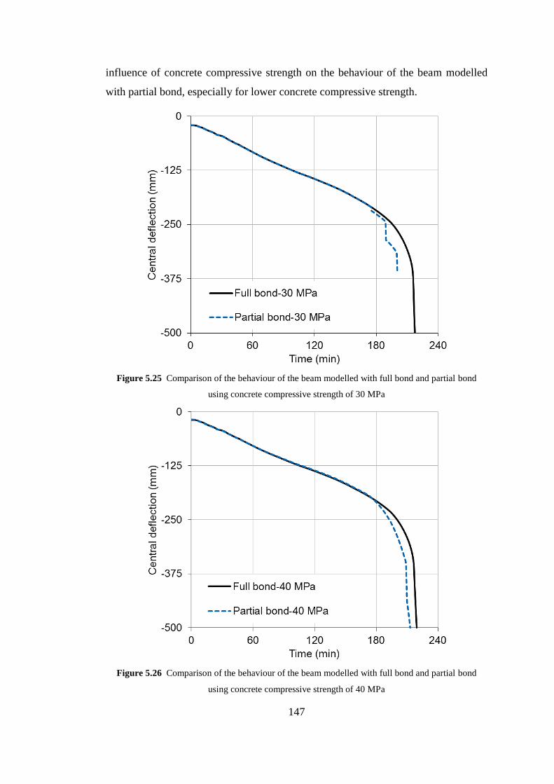
147
influence of concrete compressive strength on the behaviour of the beam modelled
with partial bond, especially for lower concrete compressive strength.
Figure 5.25 Comparison of the behaviour of the beam modelled with full bond and partial bond
using concrete compressive strength of 30 MPa
Figure 5.26 Comparison of the behaviour of the beam modelled with full bond and partial bond
using concrete compressive strength of 40 MPa

148
Figure 5.27 Comparison of the behaviour of the beam modelled with full bond and partial bond
using concrete compressive strength of 45 MPa
Figure 5.28 Influence of concrete compressive strength on the behaviour of the beam modelled with
full bond

149
Figure 5.29 Influence of concrete compressive strength on the behaviour of the beam modelled with
partial bond
5.4 Modelling isolated simply supported reinforced concrete slab
Figures 5.30 and 5.31 show an isolated simply supported reinforced concrete slab
floor heated by ISO 834 standard fire. The slab has the same dimensions and loading
condition of the slab floor within the generic building (see Figure 5.1). Hence, the
dimensions of the slab are 7.5 m x 7.5 m and the load condition was 10.75 kN/m2.
Concrete compressive strength was 45 MPa and yield stress of the reinforcing steel
bar was 460 MPa. The slab has two orthogonal reinforcing steel bar layers with steel
area of 646 mm2/m for each layer.
As shown in Figure 5.30, the slab was modelled as an assembly of 25 nine-node
plain concrete slab elements, 50 three-node reinforced steel bar elements (25
elements in each direction) and 85 two-node bond link elements which connected the
plain concrete slab elements to steel bar elements. Hence, the influence of the bond
between concrete and reinforcing steel bars can be modelled as partial or full bond
conditions. The cross-section of the slab was subdivided into 14 layers in order to
perform the thermal and structural analysis.

150
Figure 5.30 Details of the isolated slab modelled
Figure 5.31 The cross-section of the slab modelled
5.4.1 The effect of concrete cover on the behaviour of the slab
As mentioned before, concrete cover is an important part of reinforced concrete
members especially under fire conditions. Concrete cover provides a protection to
fire exposure, as well as gives a confinement to the steel bars for anchorage. For
considering the influence of concrete cover on the behaviour of the slab under fire

151
condition, five thicknesses of concrete cover (10, 15, 20, 25 and 30 mm) were
adopted in this study. Figure 5.32 shows the temperature histories of the reinforcing
steel bars for different thicknesses of concrete covers under ISO 834. It is evident
that the temperatures of reinforcing steel bars are significantly affected by the
concrete covers.
Figure 5.32 Time-temperature histories of the reinforcing steel bars with different concrete covers
under ISO 834 fire
The structural analyses were carried out for each thickness of concrete cover using
both full bond and partial bond conditions. Figures 5.33 to 5.37 present the
comparison of the central deflections of the slab modelled as full bond or partial
bond using different thicknesses of concrete cover.
It can be seen from Figure 5.37 that there is no big difference between the
deflections of the slab modelled with full or partial bond when the concrete cover
was 30 mm. However, when the slab cover was decreased to 25 mm and 20 mm, a
clear different can be observed between the cases of full and partial bond, as shown
in Figure 5.36 and Figure 5.35. This difference becomes greater when the concrete
covers were 10 mm and 15 mm as illustrated in Figure 5.33 and Figure 5.34
respectively. This behaviour is mainly due to the increasing of the bond temperature

152
(see Figure 5.32). Based on the output data from the modelling, the failure of the slab
with 10 mm concrete cover and full bond was due to rupture of many steel bars. This
rupture of the steel bars is attributed to the full bond between concrete and the
reinforcement in which the high steel strain was concentrated at some locations
within the slab. However, when the slab was modelled with partial bond, just few
elements were ruptured. This behaviour is attributed to the relative slips between the
bars and concrete in which the steel strains within the steel bars can be more
uniformly distributed along the length of the steel bars.
Similar behaviour was observed for 15 mm concrete cover with few bars ruptured,
which leads to more divergence between the full and partial bond cases. In the case
of 20 mm and 25 mm concrete covers, the slab failed mainly due to bond failure for
partial bond, and also due to yielding of steel bars for full bond. For the slab with
concrete cover of 30 mm, the failure of the slab with full bond was because of
yielding of some steel bars while for partial bond just few bond elements failed.
Figure 5.38 shows the influence of different concrete covers on the central
deflections of the slab modelled as partial bond.
Figure 5.33 Comparison of the central deflections of the slab modelled as full bond or partial bond
using concrete cover of 10 mm

153
Figure 5.34 Comparison of the central deflections of the slab modelled as full bond or partial bond
using concrete cover of 15 mm
Figure 5.35 Comparison of the central deflections of the slab modelled as full bond or partial bond
using concrete cover of 20 mm

154
Figure 5.36 Comparison of the central deflections of the slab modelled as full bond or partial bond
using concrete cover of 25 mm
Figure 5.37 Comparison of the central deflections of the slab modelled as full bond or partial bond
using concrete cover of 30 mm

155
Figure 5.38 Influence of different concrete covers on the central deflections of the slab modelled as
partial bond
5.4.2 The effect of concrete strength on the behaviour of the slab
To investigate the influence of concrete strength on the behaviour of the slab, the
same isolated slab with concrete cover of 30 mm and steel bars yielding strength of
460 MPa was used. Four values of concrete compressive strength (20, 30, 40 and 45
MPa) were adopted in this study. The temperature history of the reinforcing steel
bars mesh within the slab is shown in Figure 5.39.
The effect of concrete compressive strength on the response of the slab is shown in
Figures 5.40 to 5.43. It can be seen from the figures that there was no great influence
when the compressive strength was more than 40 MPa. However, the slab failed
earlier when the compressive strength was less than 30 MPa. Generally, the effects
of concrete compressive strengths on the behaviours of the slab were not significant,
as shown in Figure 5.44.

156
Figure 5.39 Time-temperature history of the reinforcing steel bars within the slab exposed to ISO 834
fire
Figure 5.40 Comparison of the central deflections of the slab modelled as full bond or partial bond
using concrete compressive strength of 20MPa

157
Figure 5.41 Comparison of the central deflections of the slab modelled as full bond or partial bond
using concrete compressive strength of 30MPa
Figure 5.42 Comparison of the central deflections of the slab modelled as full bond or partial bond
using concrete compressive strength of 40MPa

158
Figure 5.43 Comparison of the central deflections of the slab modelled as full bond or partial bond
using concrete compressive strength of 45MPa
Figure 5.44 Influence of different concrete strengths on the central deflections of the slab modelled as
partial bond

159
5.5 Modelling of reinforced concrete frame structure in fire
After conducting the studies on the behaviour of individual reinforced concrete
members at elevated temperatures, it is important to investigate behaviour of these
members within a building. The structural members within a real building behave
differently compared to the isolated members. Fire in a building is normally
localised in the areas called fire compartments. These fire compartments are
surrounded by the cooling regions. The surrounding cooling structures can provide a
considerable restraint to the members that effected by the fire. The behaviours of
these members are influenced by the locations of the members within the building.
Using isolated member subjected to standard fire curve gives the upper and lower
limits of the member, but does not give the real behaviour of the member within the
building.
Therefore, in this section a 3D reinforced concrete frame with floor slabs was
modelled under different fire scenarios. It was assumed that concrete compressive
strength was 45 MPa and the yield strength of the steel bar was 460 MPa. The details
of the whole floor were shown in Figure 5.1. The same beam shown in Figure 5.3
and Figure 5.4, and the same slab shown in Figure 5.30 and 5.31 were used. The
concrete cover of the beam was 30 mm, while the concrete covers of the slab and
column were 25 mm. Due to very high computational power demanded, the frame
was modelled using only full bond between concrete and reinforcement.
As shown in Figure 5.45, a quarter of the floor was modelled due to symmetry in this
study. For the first case, it was assumed that the whole floor of the building was
engulfed by ISO 834 standard fire. Figure 5.46 shows the deflections at positions a,
b, and c (see Figure 5.45). It can be seen from the figure that the deflections at three
positions of the floor slabs were approximately similar with little less deflection at
position b. This is due to the continuity of the slabs and the restraint provided by
some columns.
In order to investigate the influence of different locations of fire compartments on
the structural behaviour of floor slabs. Six locations of fire compartments were
investigated in this study. Figure 5.45 gives the locations of the fire compartments
which were identified as FC-1, FC-2, FC-3, FC-4, FC-5 and FC-6. Only one fire
compartment was exposed to ISO 834 standard fire while the rest of the structure

160
was assumed to be at ambient temperature. Figure 5.47 gives the central deflections
of the floor slabs for different fire compartments. It can be seen from the figure that
the lowest central deflection was the fire compartment FC-3 and highest central
deflection was the fire compartment FC-1. The central deflections of the fire
compartments FC-2 and FC-6 were similar. Also there were similar central
deflections for the fire compartments FC-4 and FC-5.
Figure 5.45 Floor layout of the building with different locations of the fire compartments
From this study it is clear that restraint provided by the cool structures surrounding
the fire compartment has a positive effect on the fire resistance of the structural
members within the fire compartment. The compressive membrane action may play
important role to enhance the loading capacity of the floor slabs within the fire
compartment. Figures 5.48 to 5.50 show the comparisons of the deflections at three
locations for compartment fire and whole floor fire, together with the central
deflection of isolated simply supported slab. It is evident from the figures that the
deflections of the slabs subjected to whole floor fire were greater than the deflections
of the slabs under compartment fires. This is because under whole floor fire only

161
very limited restraint was provided by columns for the floor slabs. It is also clear
that the behaviour of isolated simply supported slab was considerably different with
the slab within the structures.
Figure 5.46 The deflections of the floor slabs at the position a, b and c under whole floor fire
Figure 5.47 Comparison of the central deflections of the floor slabs for different fire compartments

162
Figure 5.48 Comparison of the deflections at Position a for compartment fire FC-1 and whole floor
fire, together with the central deflection of isolated simply supported slab.
Figure 5.49 Comparison of the deflections at Position b for compartment fire FC-2 and whole floor
fire, together with the central deflection of isolated simply supported slab.
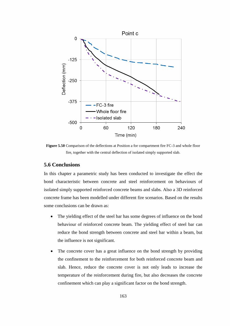
163
Figure 5.50 Comparison of the deflections at Position a for compartment fire FC-3 and whole floor
fire, together with the central deflection of isolated simply supported slab.
5.6 Conclusions
In this chapter a parametric study has been conducted to investigate the effect the
bond characteristic between concrete and steel reinforcement on behaviours of
isolated simply supported reinforced concrete beams and slabs. Also a 3D reinforced
concrete frame has been modelled under different fire scenarios. Based on the results
some conclusions can be drawn as:
The yielding effect of the steel bar has some degrees of influence on the bond
behaviour of reinforced concrete beam. The yielding effect of steel bar can
reduce the bond strength between concrete and steel bar within a beam, but
the influence is not significant.
The concrete cover has a great influence on the bond strength by providing
the confinement to the reinforcement for both reinforced concrete beam and
slab. Hence, reduce the concrete cover is not only leads to increase the
temperature of the reinforcement during fire, but also decreases the concrete
confinement which can play a significant factor on the bond strength.

164
The impact of concrete spalling on the beam is very significant for both full
bond and partial bond cases. However, the effect of spalling on the beam
modelled with partial bond is greater than that modelled with full bond.
For reinforced concrete beam it is clear that when the concrete compressive
strength is more than 40 MPa, there is no significant effect on the bond
behaviour. And the behaviour of the beam modelled with full or partial bond
is similar. However, great influence can be observed when the concrete
compressive strength is less than 40 MPa. This behaviour can be attributed to
the considerable degradation of the bond strength. The influence of concrete
compressive strength on the slab is less significant.
The results generated from 3D modelling of concrete frame indicate that
restraint provided by the cool structures surrounding the fire compartment
has a positive effect on the fire resistance of the structural members within
the fire compartment. The compressive membrane action may play important
role to enhance the loading capacity of the floor slabs within the fire
compartment. It is also clear that the behaviour of isolated simply supported
slab was considerably different with the slab within the structures.
165
Chapter 6 Conclusions and recommendations for
future works
For the last two decades considerable progress has seen made on our understanding
of reinforced concrete structures under fire conditions. It is well known that the bond
behaviours between concrete and reinforcing steel bars or strands have significant
influences on the behaviours of reinforced concrete and prestressed concrete
members. Conventionally, design of reinforced concrete structure is based on the
assumption of the strain compatibility between concrete and steel bars. This
assumption requires a good bond between concrete and steel bars. Current research
indicates that bond strength between concrete and steel reinforcement plays an
important role for assessing the fire resistance of reinforced concrete and prestresed
concrete structures. The robustness of bounds is therefore vitally important to the fire
resistance of reinforced concrete buildings. The development of effective bond
models is a key issue in this research field. The PhD research reported here focused
specifically on the development of robust models for modelling the bond
characteristics between concrete and reinforcing steel or strands at elevated
temperatures.
6.1 Summary of thesis contributions
6.1.1 Development of a robust model to simulate the bond stress-slip
between concrete and steel bars at elevated temperatures
The first contribution of this PhD research is to develop a new model for predicting
the bond stress-slip between concrete and reinforcing steel bars at elevated
temperatures. The model is based on the thick-wall cylinder theory with considering
of partially cracked concrete cover. In this model the smeared crack approach for
concrete in tension is adopted. Hence, the model can take into account the splitting
failure of the concrete cover. The degradation of the bond strength at elevated
temperatures is related to the concrete material properties changed with
temperatures.
The developed bond stress-slip model has been incorporated into VULCAN software
using the two-node bond-link element approach for considering the influence of
166
bond characteristic on structural behaviours of reinforced concrete structural
members at elevated temperatures. A series of validations have been conducted using
the previous tested results generated by different researchers. Reasonable agreements
have been achieved between the predicted results from the model and the
experimental data.
6.1.2 Development of a new model to simulate bond stress-slip
between the concrete and prestressed strands in fire
The second contribution of this PhD research is to develop a robust model to
simulate the bond stress-slip between concrete and strands for prestressed concrete
structures at elevated temperatures. The model was based on the mechanical
interlocking between prestressing steel strands and surrounding concrete as well as
considering the effect of Poisson’s ratio (Hoyer effect). The model takes into account
the variation of the concrete properties and strands’ geometries, as well as effect of
the cohesion and friction between the strands and concrete. The degradation of the
bond strength at elevated temperatures is related to the concrete material properties
changed with temperature.
The developed bond stress-slip model has been incorporated into the VULCAN
software by using two-node bond-link element approach for analysing the structural
behaviours of prestressed concrete structural members in fire. A series of validations
have been conducted using the previous tested data. Reasonable agreements have
been achieved between the predicted results from the model in comparison with the
tests results.
6.1.3 Parametric study on the bond behaviour at elevated
temperatures
The third contribution of this PhD research is to conduct a series of comprehensive
parametric studies for investigating the influence of the bond stress-slip on the
response of reinforced concrete beam and slab members under fire conditions. The
main factors, which effect on the bond stress-slip behaviour, have been identified.
These factors are: reinforcing steel bars’ yielding, the thickness of concrete cover,
concrete compressive strength and concrete spalling. Also a 3D reinforced concrete
frame has been modelled under different fire scenarios. The behaviours of the

167
reinforced concrete structural members within a whole building have been compared
to the behaviours of isolated members under the same fire conditions. Some
interesting results have been generated.
6.2 Conclusions
Based on the validations of the developed bond models, the numerical studies, and a
series of comprehensive parametric studies for investigating the influence of the
bond stress-slip on the behaviour of reinforced concrete beam and slab members
under fire conditions, the following conclusions can be drawn:
(1) The validation results of the bond model for simulating the interaction
between concrete and reinforcing steel bars show good agreement between
the model predictions and experimental data. The developed model is able to
predict the bond-slip characteristic between the concrete and reinforcing steel
bar at elevated temperatures. The model takes into account the variation of
concrete properties, concrete covers and the geometries of rebar.
(2) The validation results of the bond model for predicting the bond stress-slip
between strands and concrete for prestressed concrete members under fire
conditions show reasonable agreements between the predicted results and
tests results. The model is able to predict the bond-slip characteristic between
the concrete and strands for three-wire and seven-wire strands at elevated
temperatures. This model can be used to calculate the bond-slip for the
transfer length (push-in bond) and flexural length (pull-out bond) within the
prestressed concrete members. Also, the model is able to take into account
different strand’s diameters and different strand’s surfaces (smooth or
indented).
(3) The research indicated that the strength of the bond between concrete and
reinforcing steel bars plays a very important role that can affect the fire
resistance of reinforced concrete structures, especially when the temperature
of the reinforcing steel bar is high (more than 400 °C). Therefore, the
assumption of the perfect bond condition for the analysis of reinforced
concrete structures under fire conditions is un-conservative.
(4) The yielding effect of the steel bar has some degrees of influence on the bond
behaviour of reinforced concrete beam. The yielding effect of steel bar can
168
reduce the bond strength between concrete and steel bar within a beam, but
the influence is not significant.
(5) The concrete cover has a great influence on the bond strength by providing
the confinement to the reinforcement for both reinforced concrete beam and
slab. Hence, reduce the concrete cover is not only leads to increase the
temperature of the reinforcement during fire, but also decreases the concrete
confinement which can play a significant role on the bond strength.
(6) The impact of concrete spalling on the beam is very significant for modelling
both full bond and partial bond cases. However, the effect of spalling on the
beam modelled with partial bond is greater than that modelled with full bond.
(7) For reinforced concrete beam it is clear that when the concrete compressive
strength is more than 40 MPa, there is no significant effect on the bond
behaviour. And the behaviour of the beam modelled with full or partial bond
is similar. However, great influence can be observed when the concrete
compressive strength is less than 40 MPa. This behaviour can be attributed to
the considerable degradation of the bond strength. The influence of concrete
compressive strength on the slab is less significant.
(8) The results generated from 3D modelling of concrete frame indicate that
restraint provided by the cool structures surrounding the fire compartment
has a positive effect on the fire resistance of the structural members within
that fire compartment. The compressive membrane action may play
important role to enhance the loading capacity of the floor slabs within the
fire compartment. It is also clear that the behaviour of isolated simply
supported slab was considerably different with the slab within the structures.
6.3 Recommendations for future studies
It is clear from this PhD research that there are questions to be addressed, regarding
the behaviour of bond characteristics between concrete and steel bars or prestressed
strands at elevated temperatures. In summary, it is recommended that the following
areas should be considered for further works:
(1) The developed models in this research consider monotonic loading
conditions only. However, the frame works of the current proposed models
can be further extended and developed to consider cyclic loading conditions

169
for the bond stress-slip of reinforced concrete and prestressed concrete
structures subjected to dynamic or seismic loading conditions.
(2) Experimental data on the bond behaviours of reinforce concrete and
prestressed concrete members at elevated temperatures are still very limited.
An extension of research to produce more test data is necessary for the
validations and improvements of proposed models.
(3) In this research the developed models only consider the confinement
influence of concrete cover. However, the models can be further improved to
take into account the confinement provided by stirrups or shear steels.
(4) More experiments are needed to assess the influences of different concrete
covers, different concrete compressive strengths. The further tested data can
be used to compare the results generated from the parametric studies using
current models.
(5) Further numerical study is needed to investigate the bond behaviours of beam
and slab members within the large frame structures under different fire
conditions.

170
REFERENCES
Abrishami, H. & Mitchell, D., (1993). Bond characteristic of pretensioned strand.
ACI Materials Journal, 90(3), pp. 228-235.
Arioz, O., (2007). Effects of elevated temperatures on properties of concrete. Fire
Safety Journal, Volume 42, pp. 516-522.
ASHI Reporter, (2007). The effects of fire on structural systems, s.l.: American
Society of Home Inspectors.
Aslani, F. & Bastami, M., (2011). Constitutive Relationships for Normal-and High-
Strength Concrete at Elevated Temperatures. ACI Material Journal, 108(4), pp. 355-
364.
ASTM E119, (2000). Standard test methods for fire tests of building construction
and materials. United States: ASTM Committee E05.
Badiger, N. & Malipatil, K., (2014). Parametric Study on Reinforced Concrete Beam
using ANSYS. Civil and Environmental Research, 6(8), pp. 88-94.
Bailey , C., (2002). Holistic behaviour of concrete buildings in fire. Proceedings of
the ICE, Structures and Buildings, 152(3), pp. 199-212.
Bailey, C. & Ellobody, E., (2009). Fire tests on bonded post-tensioned concrete
slabs. Engineering Structures, Volume 31, p. 686–696..
Barzegar, J. F. & Schnobrich, W., (1986). Nonlinear Finite Element Analysis of
Reinforced Concrete Under Short Term Monatomic Loading, s.l.: A report on a
research project, University of Illinois at Urbana-Champaign, research series
No.530.
Bazant, z. & Kaplan, M., (1996). Concrete at high temperatures, s.l.: Longman
Group.
Benitez, J. & Galvez, J., (2011). Bond modelling of prestressed concrete during the
prestressing force release. Materials and Structures, Volume 44, pp. 263-278.
BIGAJ A. J., (1999). Structural dependence of rotation capacity of plastic hinges in
rc beams and slabs, s.l.: s.n.

171
Bisby, L., (2012). Opportunities for performance-based fire resistance design of frp
reinforced concrete slabs, Edinburgh: BRE Centre for Fire Safety Engineering, The
University of Edinburgh.
Bizri, H., (1973). Structural capacity of reinforced concrete columns subjected to
fire induced thermal gradients, Berkeley,: Structural Engineering Laboratory, Report
No. 73-1,University of California,.
Bolmsvik, R. & Lundgren, K., (2006). Modelling of bond between three-wire strands
and concrete. Magazine of Concrete Research, 58(3), pp. 123-133.
Bowden, . F. P., Moore, A. & Tabor, D., (1942). The ploughing and adhesion of
sliding metals, s.l.: Council for scintific and industrial research, Bulletin no. 145.
Brown, C. J., Darwin, D. & McCabe, S. L., (1993). Finite Element Fracture Analysis
of Steel-Concrete Bond, Kansas: SM Report No. 36, University of Kansas Center for
Research.
Burkan, O. & Ghani, A., (2004). Finite element modeling of coupled heat
transfer,moisture transport and carbonation processes in concrete structures. Cement
& Concrete Composites, Volume 26, pp. 57-73.
Burns, N. & Siess, C. P., (1962). Load-deformation characteristics of beam-column
connections in reinforced concrete, Urbana: Civil engineering Studies SRS No.234,
University of Illinois.
CEB-FIP Model code 90, (1991). s.l.:Final draft ,Committe euro-international du
beton. Bulletin d'information No.203-205.
CEB-FIP, 2010. CEB-FIP Model code (2010). First complete draft ed.
s.l.:International Federation for Structural Concrete.
CEB-FIP-Bulletin10, (2000). Bond of Reinforcement in Concrete. s.l.:s.n.
CEN EUROPEAN STANDARD, (2004). Eurocode 2: Design of concrete structures
- Part 1-1 : General rules and rules for buildings. London: British Standards
Institution.
CEN, (2002). Eurocode 1: Actions on structures-Part 1-2 General actions – Actions
on structures exposed to fire. s.l.:BS EN 1991-1-2:2002.

172
CEN, (2004a). Eurocode 2: Design of concrete structures - Part 1-2: General rules -
Structural fire design. London: BS EN 1992-1-2.
CEN, (2004b). Design of concrete structures. Part 1.1: general rules and rules for
buildings. London: BS EN 1992-1-1.
Choi O.C. and Yang S.Y., (2010). Bond analysis model of deformed bars to
concrete. Fracture Mechanics of Concrete and Concrete Structures -Assessment,
Durability, Monitoring and Retrofitting of Concrete Structures- B. H. Oh, et al.
(eds),Korea Concrete Institute, Seoul, ISBN 978-89-5708-181-5.
Choi, O., Choi, H. & Hong, G., (2010). Bearing angle model for bond of reinforcing
bars to concrete, Seoul: Korea Concrete istitute, ISBN 978-89-5708-181-5.
Cowen, . H. S. & VanHorn, A. D., (1967). End support on ultimate flexural bond in
pre-tensioned beams., Pennsylvania: Bond in prestressed concrete progress report
No. 3, Fritz engineering laboratory, Department of civil engineering, Lehigh
University, Bethlehem.
Curtis, D., (2011). Estimated shear strength of shear keys and bonded joints in
concrete dams. San Diego, California, 31st Annual USSD Conference.
Diederichs , U. & Schneider, U., (1981). Bond strength at high temperatures.
Magazine of concrete research, 33(115), pp. 75-84.
Dzhafarov, Y. & Rozhenko, A. F., (1968). Effect of temerature on th friction
characteristics of composite materials. Institute of Materials Science , 10(70), pp. 80-
84..
Elghazouli, A., Cashell, K. & Izzuddin, B., (2009). Experimental evaluation of the
mechanical properties of steel reinforcement at elevated temperature.
FireSafetyJournal, Volume 44, p. 909–919.
Ervine, A., (2012). Damaged reinforced concrete structures in fire, s.l.: PhD thesis,
University of Edinburgh.
Eunsoo Ch., Young-Soo Ch., Yeon-Wook K. and Joo-Woo K., (2010). Monotonic
and cyclic bond behavior of confined concrete using NiTiNb SMA wires. SMART
MATERIALS AND STRUCTURES, Volume 20.
173
Fellinger, J., Stark, J. & Walraven, J., (2003). Bond model for prestressed strands in
fire exposed concrete. Reston, AV, American Society of Civil Engineers.
Fib Bulletin 46, (2008). Fire Design of Concrete Structures-Structural Behaviour
and Assessment. s.l.: fib Fédération internationale du béton - Building, Fireproof.
Fu Y.F, Wong Y.L., Tang C.A. and Poon C.S., (2004). Thermal induced stress and
associated cracking in cement-based composite at elevated temperatures––Part
I:Thermal cracking around single inclusion. Cement & Concrete Composites ,
Volume 26, pp. 99-111.
Galvez , J. et al., (2009). Splitting failure of precast prestressed concrete during the
release of the prestressing force. Engineering Failure Analysis , Volume 16, p.
2618–2634.
Gao, W., Jian-Guo Dai, J., Teng, J. & Chen, G., (2013). Finite element modeling of
reinforced concrete beams exposed to fire. Engineering Structures, Volume 52, p.
488–501.
George S. and Mario B., (2010). Rebar pullout testing under dynamic Hopkinson bar
induced impulsive loading. Materials and Structures, Volume 43, pp. 247-260.
Goto, Y., (1971). Cracks formed in concrete around deformed tension bars. ACI-
Journal, pp. 244-251.
Griffin, B. & Beavis, M., (1992). Fire resistance of prestressed concrete, s.l.:
University of Canterbury.
Gustavson, R., (2004). Experimental studies of the bond response of three-wire
strands and some influencing parameters. Materials and Structures, Volume 37, pp.
96-106.
Haddad , R., Al-Saleh , R. & Al-Akhras, N., (2008). Effect of elevated temperature
on bond between steel reinforcement and fiber reinforced concrete. Fire Safety
Journal, Volume 43, pp. 334-343.
Haddad, R. & Shannis, L., (2004). Post-fire behavior of bond between high strength
pozzolanic concrete and reinforcing steel. Construction and Building Materials,
Volume 18, pp. 425-435.

174
Hertz, K., (1982). The anchorage capacity of reinforcing bars at normal and high
temperatures. Magazine of Concrete Research, Volume 34, pp. 213-220.
Hou, X., Kodur, V. & Zheng, W., (2015). Factors governing the fire response of
bonded prestressed concrete continuous beams. Materials and Structures, 48(9), pp.
2885-2900.
Huang, Z., (1995). The analysis of thermal and fire performance of cementitious
building components, s.l.: PhD Thesis, University of Central Lancashire.
Huang, Z., (2010). Modelling of reinforced concrete structures in fire. Engineering
and Computational Mechanics, Volume 163, pp. 43-53.
Huang, Z., (2010). Modelling the bond between concrete and reinforcing steel in
fire. Engineering Structures, Volume 32, pp. 3660-3669.
Huang, Z., Burgess, I. & Plank, R., (2003b). Modelling membrane action of concrete
slabs in composite buildings in fire. Part II: validations.. Journal of Structural
Engineering, 129(8), pp. 1103-1112.
Huang, Z., Burgess, I. & Plank, R., (2007). Three-dimensional analysis of reinforced
concrete beam–column structures in fire, Sheffield: Department of Civil and
Structural Engineering, University of Sheffield. Research Report DCSE/07/F/4..
Huang, Z., Burgess, I. & Plank, R., (2009). Three-dimensional analysis of reinforced
concrete beam–column structures in fire. Journal of Structural Engineering, ASCE,
135(10), p. 1201–1212.
Huang, Z., Burgess, I. W. & Plank, R. J., (1999). Nonlinear analysis of reinforced
concrete slabs subjected to fire. ACI Structural Journal, 96(1), pp. 127-135.
Huang, Z., Burgess, I. W. & Plank, R. J., (2003a). Modelling membrane action of
concrete slabs in composite buildings in fire. Part I: Theoretical development.
JOURNAL OF STRUCTURAL ENGINEERING, 129(3), pp. 1093-1102.
Huang, Z., Platten, A. & Roberts, J., (1996). Non-linear finite element model to
predict temperature histories within reinforced concrete in fires. Building and
Environment, 31(2), pp. 109-118.
Huanzi, W., (2009). An analytical study of bond strength associated with splitting of
concrete cover. Engineering Structures, Volume 31, pp. 968-975.

175
ISO-834, (1975). Fire resistance test, elements of building constructions.
s.l.:International Standard ISO 834..
John Robert Prince M. and Bhupinder S., (2013). Bond behaviour of deformed steel
bars embedded in recycled aggregate concrete. Construction and Building Materials,
Volume 49, p. 852–862.
Kodur, V. & Shakya, A., (2014). Modeling of the response of precast prestressed
concrete hollow-core slabs exposed to fire. PCI Journal , 59(3), pp. 78-94.
Kodur, V., (2014). Properties of concrete at elevated temperatures, s.l.: Hindawi
Publishing Corporation,ISRN Civil Engineering,Article ID 468510.
Kumar, M. & Paulo, J., (2006). Concrete microstructure, properties and materials.
Third Edition ed. United States: McGraw-Hill.
Kumar, V., Sharma, U., Singh, B. & Bhargava, P., (2013). Effect of temperature on
mechanical properties of pre-damaged steel reinforcing bars. Construction and
Building Materials, Volume 46, pp. 19-27.
Law, A., (2016). The role of modelling in structural fire engineering design. Fire
Safety Journal, Volume 80, p. 89–94.
Lee, H. & Noguchi, T., (2002). Evaluation of the bond properties between concrete
and reinforcement as a function of the degree of reinforcement corrosion. Cement
and Concrete Research, Volume 32, p. 1313–1318.
Legeron, F., Paultre, P. & Mazars, J., (2005). Damage mechanics modelling of
nonlinear seismic behaviour of concrete structures. Journal of Structural
Engineering, 131(6), pp. 946-955.
Lin, S., (2014). Development of robust connection models for steel and composite
structures in fire, s.l.: PhD Thesis, Brunel University London.
Lin, T., Ellingwood, B. & Piet , O., (1987). Flexural and shear behaviour of
reinforced concrete beams during fire tests, s.l.: Report no. NBS-GCR-87-536.
Center for Fire Research, National Bureau of Standards.
Losberg, A., (1964). Anchorage of beam reinforcement shortened according to the
moment distribution curve., s.l.: Seventh Congrress of the IABSE, Final
Report,http://doi.org/10.5169/seals-7977, pp. 383-392.

176
Lundgren, K., (2002). Steel-encased pull-through tests of seven-wire strands,
Sweden : Department of Structural Engineering Concrete Structures, Chalmers
University of Technology, Report No. 02:13..
Lutz, L., (1970). Analysis of stresses in concrete near a reinforcing bar due to bond
and transverse cracking. ACI-Journal, pp. 778-787.
Lutz, L., (1970). Information on the bond of deformed bars from special pull-out
test. ACI-Journal, pp. 885-887.
Malvar L. J., (1991). Bond of Reinforcement Under Controlled Confinement,
California: Naval Civil Engineering Laboratory Port Hueneme, CA 93043-5003.
Marti-Vargas, J., Serna, P. & Hale, W., (2013). Strand bond performance in
prestressed concrete accounting for bond slip. Engineering Structures, Volume 51,
pp. 236-244.
Moore, W., (2008). Performance of fire-damaged prestressed concrete bridges, s.l.:
Missouri University of Science and Technology, Masters Theses.
Morley , P. & Royles, R., (1983). Response of the bond in reinforced concrete to
high temperatures. Magazine of Concrete Research, 35(123), pp. 67 - 74.
MORLEY P. D. and ROYLES R., (1979/80). The Influence of High Temperature on
the Bond in Reinforced Concrete. Fire Safety Journal, pp. 243 - 255.
Morley, P., (1982). Effects of elevated temperature on bond in reinforced concrete.
s.l.:PhD Thesis, University of Edinburgh.
Nielsen C. V. and Bicanic N., (2002). Radial fictitious cracking of thick-walled
cylinder due to bar pull-out. Magazine of Concrete Research, 54(3), pp. 215-221.
NUREG/CR-7031, (2010). A compilation of elevated temperature concrete material
property data and information for use in assessments of nuclear power plant
reinforced concrete. s.l.:U.S.NRC,Office of Nuclear Regulatory Research.
ODBM, (2000). The Building Regulations 2000: The Approved Documents:SI
2000/2531, UK: s.n.
Osterman, J., (1951). Proposed revisions to manual of standard practice for detailing
reinforced concrete structures. ACI-Journal, pp. 349-351.

177
Pantazopoulou S. J. and K. D. Papoulia K. D., Members, ASCE, (2001). Modeling
cover-cracking due to reinforcement corrosion in rc structures. Journal of
Engineering Mechanics, 127(4), pp. 342 - 351.
Phan, L., McAllister, T., Gross, J. & Hurley, M., (2010). Best practice guidelines for
structural fire resistance design of concrete and steel buildings, s.l.: National
Institute of Standards and Technology,NIST Technical Note 1681.
Pothisiri , T. & Panedpojaman, P., (2013). Modeling of mechanical bond–slip for
steel-reinforced concrete under thermal loads. Engineering Structures, Volume 48,
pp. 497-507.
Pothisiri, T. & Panedpojaman, P., (2012). Modeling of bonding between steel rebar
and concrete at elevated temperatures. Construction and Building Materials, Volume
27, pp. 130-140.
Rehm, G., (1961). On the fundamentals of steel-concrete bond, Germany: s.n.
Rivera, O. et al., (2016). Effect of elevated temperature on alkali-activated
geopolymeric binders compared to portland cement-based binders. Cement and
Concrete Research , Volume 90 , p. 43–51.
Rombach, G., (2004). Finite element design of concrete strutures. London: Thomas
Telford.
Russel, B. & Burns, N., (1993). Design guidelines for transfer development and
deboning of large diameter seven wire strands in pretensioned concrete girders,
Austin: The University of Texas, Research report 1210-5F.
Sakai , T., Kanakubo , T., Yonemaru, K. & Fukuyama, H., (1999). Bond splitting
behavior of contiuous fiber reinforced concrete members. Fiber Reinforced Polymer
for Reinforced Concrete Structures,, s.l.: ACI SP-188; 1131-1144..
Tadros, M. & Morcous, G., (2011). Impact of Large 0.7 in. Strand on NU-I Girders,
s.l.: Final Reports Technical Briefs from Mid-America Transportation Centre.
Tepfers R., (1979). Cracking of concrete cover along anchored deformed reinforcing
bars. Magazine of concrete research, 31(106), pp. 3-12.
Tepfers, R., (1980). Bond stress along lapped reinforcing bars. Magazine of
Concrete Research, 32(112), pp. 3-12.

178
Tepfers, R., (1982). Lapped tensile reinforcement splices. Journal of the Structural
Division, pp. 283-301.
The Concrete Centre, (2006). How to design reinforced concrete flat slabs using
finite element analysis, Surrey: The Concrete Centre,ISBN 1-904818-37-4.
Timoshenko , S. & Goodier, J. N., 1951. Theory of Elasticity. s.l.:McGraw-Hill
Book Company.
Uijl, J. & Bigaj, A., (1996). A bond model for ribbed bars based on concrete
confinement, s.l.: Delft university of technology, HERON, 41(3),ISSN 0046-7316.
Valcuende M. and Parra C., (2009). Bond behaviour of reinforcement in self-
compacting concretes. Construction and Building Materials, Volume 23, pp. 162-
170.
Vázquez-Herrero, C., Martínez-Lage, I. & Aguilar, G., (2013). Evaluation of strand
bond properties along the transfer length of prestressed lightweight concrete
members. Engineering Structures , Volume 49, pp. 1048-1058.
Viwathanatepa, S., Popov, E. & Bertero, V., (1979). Effects of generalized loadings
on bond of reinforcing bars embedded in confined concrete blocks, Berkeley:
Earthquake Engineering Research Center, University of California, Report No EERC
79-22.
Wang , X. & Liu, X., (2003). A strain-softening model for steel-concrete bond.
Cement and Concrete Research, Volume 33, pp. 1669-1673.
Watstein, D., (1947). Distribution of bond stress in concrete pull-out specimens.
ACI-Journal, pp. 1041-1052.
Welsh, W. & Sozen, M., (1968). Investigation of prestressed reinforced concrete for
highway bridges, Part V: Analysis and control of anchorage-zone cracking in
prestressed concrete, Urbana: University of Illinois.
Xiao J. and Falkner H., (2007). Bond behaviour between recycled aggregate concrete
and steel rebars. Construction and Building Materials, Volume 21, p. 395–401.
Yu, X., Huang, Z., Burgess, I. & Plank, R., (2005). Concrete spalling in fire: a
review of the current state of knowledge., Sheffield: Department of Civil and
Structural Engineering, University of Sheffield. Research report DCSE/05/F/04..

179
Zheng, W. & Hou, X., (2008). Experiment and analysis on the mechanical behaviour
of PC simply-supported slabs subjected to fire. Advances in Structural Engineering,
11(1), pp. 71-89.