Embed Size (px)
Citation preview
1 INTRODUCTION
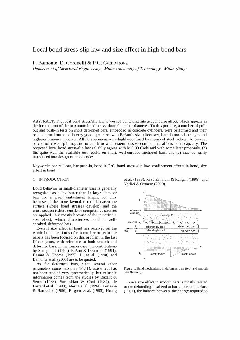
Bond behavior in small-diameter bars is generally recognized as being better than in large-diameter bars for a given embedment length, not only because of the more favorable ratio between the surface (where bond stresses develop) and the cross-section (where tensile or compressive stresses are applied), but mostly because of the remarkable size effect, which characterizes bond in well-enrobed, deformed bars.
Even if size effect in bond has received on the whole little attention so far, a number of valuable papers has been focused on this problem in the last fifteen years, with reference to both smooth and deformed bars. In the former case, the contributions by Stang et al. (1990), Baåant & Desmorat (1994), Baåant & Thoma (1995), Li et al. (1998) and Bamonte et al. (2003) are to be quoted.
As for deformed bars, since several other parameters come into play (Fig.1), size effect has not been studied very systematically, but valuable information comes from the studies by Baåant & Sener (1988), Soroushian & Choi (1989), de Larrard et al. (1993), Morita et al. (1994), Lorraine & Hamouine (1996), Elfgren et al. (1995), Huang
et al. (1996), Reza Eshafani & Rangan (1998), and Yerlici & Ozturan (2000).
deformed bar
smooth bar
mostly friction mostly elastic
transverse cracking
load debonding Mode II
debonding Mode I
shearing-off
τb
crushing
τb
Figure 1. Bond mechanisms in deformed bars (top) and smooth bars (bottom).
Since size effect in smooth bars is mostly related
to the debonding localized at bar-concrete interface (Fig.1), the balance between the energy required to
Local bond stress-slip law and size effect in high-bond bars
P. Bamonte, D. Coronelli & P.G. Gambarova 'HSDUWPHQW�RI�6WUXFWXUDO�(QJLQHHULQJ���0LODQ�8QLYHUVLW\�RI�7HFKQRORJ\���0LODQ��,WDO\���
ABSTRACT: The local bond-stress/slip law is worked out taking into account size effect, which appears in the formulation of the maximum bond stress, through the bar diameter. To this purpose, a number of pull-out and push-in tests on short deformed bars, embedded in concrete cylinders, were performed and their results turned out to be in very good agreement with Baåant’s size-effect law, both in normal-strength and high-performance concrete. All 50 specimens were highly-confined by means of steel jackets, to prevent or control cover splitting, and to check to what extent passive confinement affects bond capacity. The proposed local bond stress-slip law (a) fully agrees with MC 90 Code and with some later proposals, (b) fits quite well the available test results on short, well-enrobed anchored bars, and (c) may be easily introduced into design-oriented codes.
Keywords: bar pull-out, bar push-in, bond in R/C, bond stress-slip law, confinement effects in bond, size effect in bond
increase bar debonding and that released by the concrete embedment has to be considered. The embedment length-diameter ratio plays a major role (the larger L/db, the larger the size effect), and relatively simple, fracture-mechanics models can be used to describe size effect in long, anchored bars (Stang et al., 1990; Bamonte et al., 2003).
On the contrary, in deformed bars size effect results from a variety of factors (Fig.1, see also ILE�����), like concrete cracking at right angles to the bar, concrete crushing in front of bar ribs and cover splitting along the bar. Since the last two factors are strongly dependent on the structural context, any investigation on size effect in deformed bars should try to prevent - or control - cover splitting, by applying a well-defined and uniform confinement. Furthermore, bars should be prevented from yielding, since the more plastic behavior of a partially-yielded anchored bar is at odds with the typical softening behavior of bond.
For the above reasons, investigating size effect in deformed bars requires short embedded lengths and well-enrobed specimens. This geometry minimizes the structural factors and the local bond stress-slip law can be studied as a “constituitive” law (Fig.2, see also Bamonte et al., 2002). Formulating such law is the primary objective of this research project. Other goals are: (a) to compare bond behavior in NSC and HPC; (b) to check the agreement with Baåant’s size-effect law (Fig.3); and (c) to investigate the effects of bond-induced dilatancy and those of possible partial splitting in the cover.
2 TEST PHILOSOPHY AND SPECIMEN GEOMETRY
The design of the cylindrical specimens (Fig.4) was based on four requirements: (a) uniformity of the bond-stress distribution (⇒ short embedded length); (b) strict tolerances on the bonded surface (⇒ the bars were machined at the lathe); (c) prevention or – at least – strict control of the possible splitting cracks (⇒ steel jacket for confinement); and (d) postponement of bar yielding past the full exploitation of bond.
To this end, the ratio L/db between the embedded length and the diameter was limited to 4 in HPC specimens and 5 in NSC specimens (actually 3.70 and 4.65 in push-in specimens, and 3.70 and 5.35 in pull-out specimens). The toroidal ribs were machined in accordance with the commonly-used trapezoidal profile, at right angles to bar axis and with a realistic bond index (iR = 0.086; rib height = 0.06db; front angle 45°; clear spacing 0.5db; max.
b
y,f
b,max
f
y
y 1 2 y,f 3 5 4s s s s s s s
τ
τ
τ
τ
τ
slip Figure 2. Local bond-stress/slip law for deformed bars (I), bar yielding included (II), from Huang et al., 1996 (see also
��� �
2000).
Strength or yield criterion
Linear fracture
mechanics
Nonlinear fracture
mechanics
d = characteristic size
σ , τ
Nominal
stress
at failure
N N
Figure 3. Size effect as observed in many concrete structures, with the transition from ductile to brittle failure.
db
L
L
1
2
pull-out specimen
push-in specimen
d = 5,12,18,26 mmbct
Figure 4. Specimen geometry in this study: pull-out specimens at the top, and push-in specimens at the bottom; concrete cover c = 4db; jacket thickness: t ≅ (1/4) db in NSC, and (1/2) db in HPC. All details were in perfect geometric similitude, including the reaction rings (Bamonte & Lelli, 2001). width 0.18db). High-grade steel was used (fy = 700-900 MPa), in order to delay bar yielding.
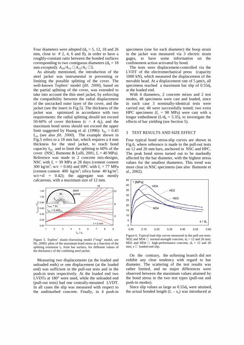
Four diameters were adopted (db = 5, 12, 18 and 26 mm, close to # 2, 4, 6 and 8), in order to have a roughly-constant ratio between the bonded surfaces corresponding to two contiguous diameters (db = 18 mm excepted): A26/A12 ≅ A12/A5 ≅ 5.
As already mentioned, the introduction of the steel jacket was instrumental in preventing or limiting the possible splitting of the cover. The well-known Tepfers’ model (ILE�� ����), based on the partial splitting of the cover, was extended to take into account the thin steel jacket, by enforcing the compatibility between the radial displacement of the uncracked outer layer of the cover, and the jacket (see the insert in Fig.5). The thickness of the jacket was optimized in accordance with two requirements: the radial splitting should not exceed 50-60% of cover thickness (c = 4 db), and the maximum bond stress should not exceed the upper limit suggested by Huang et al. (1996): τbu = 0.45 fcm (see also ILE�� ����). The example shown in Fig.5 refers to a 18 mm bar, which requires a 4 mm thickness for the steel jacket, to reach bond capacity τbu and to limit the splitting to 60% of the cover (NSC, Bamonte & Lelli, 2001, fc = 40 MPa). Reference was made to 2 concrete mix-designs, NSC with fc = 39 MPa at 28 days (cement content 300 kg/m3; w/c = 0.66) and HPC with fc = 77 MPa (cement content 400 kg/m3; silica fume 40 kg/m3; w/c+sf = 0.42); the aggregate was mostly calcareous, with a maximum size of 12 mm.
0.00
0.20
0.40
0.60
0.80
1.00
1.20
1 2 3 4 5 6 7 8 9
lcr / rb
τ b,m
ax /
fcm
t = 0 mm
4
18
τbu = 0.45fcm
8
12
τmax = pb
Figure 5. Tepfers’ elastic-fracturing model (“ring” model, see fib, 2000): plots of the maximum bond stress as a function of the splitting extension lcr from bar surface, for different values of the thickness t of the confining steel jacket.
Measuring two displacements (at the loaded and
unloaded ends) or one displacement (at the loaded end) was sufficient in the pull-out tests and in the push-in tests respectively. At the loaded end two LVDTs at 180° were used, while the unloaded end (pull-out tests) had one centrally-mounted LVDT. In all cases the slip was measured with respect to the undisturbed concrete. Finally, in 4 push-in
specimens (one for each diameter) the hoop strain in the jacket was measured via 3 electric strain gages, to have some information on the confinement action activated by bond.
The tests were displacement-controlled via the LVDT of the electromechanical press (capacity 1000 kN), which measured the displacement of the movable head. At a displacement rate of 5 µm/s, all specimens reached a maximum bar slip of 0.55db at the loaded end.
With 4 diameters, 2 concrete mixes and 2 test modes, 48 specimens were cast and loaded, since in each case 3 nominally-identical tests were carried out; 46 were successfully tested; two extra HPC specimens (fc = 98 MPa) were cast with a longer embedment (L/db = 5.35), to investigate the effects of bar yielding (see Section 5).
3 TEST RESULTS AND SIZE EFFECT
Four typical bond stress-slip curves are shown in Fig.6, where reference is made to the pull-out tests on 12 and 26 mm bars, anchored in NSC and HPC. The peak bond stress turned out to be markedly affected by the bar diameter, with the highest stress values for the smallest diameters. This trend was more clear in NSC specimens (see also Bamonte et al., 2002).
0
5
10
15
20
25
30
35
40
45
0.00 0.10 0.20 0.30 0.40 0.50 0.60
s / db
τ [MPa]
HD2
HD4
ND2
ND4
Figure 6. Typical load-slip curves measured in the pull-out tests: ND2 and ND4 ⇒ normal-strength concrete, db = 12 and 26 mm; HD2 and HD4 ⇒ high-performance concrete, db = 12 and 26 mm; s ⇒ loaded-end slip.
On the contrary, the softening branch did not exhibit any clear tendency with regard to bar diameter. The scattering of the test results was rather limited, and no major differences were observed between the maximum values attained by the bond stress in the two test types (pull-out and push-in modes).
Since slip values as large as 0.55db were attained, the actual bonded length (L – so) was introduced at
any load level, to evaluate the average bond stress (L = nominal bonded length; so = free-end slip).
As observed by Baåant et al. (1995) and confirmed by the peak values of the bond stress-slip curves, the post-peak softening exhibited by bond implies a size effect, which is common to all bond-related problems. However, only through a suitable representation of the test results it is possible to ascertain the “brittleness level” of the failure. With regard to this issue, the results of this project confirm that size effect in bond is satisfactorily described by Baåant’s law, which can be formulated as follows in the bond problem: σN - σ0 = B fc [1 + (db/d0)]
-1/2 (1) where σN = Pmax/(πdb
2/4); σ0 = Pres/(πdb2/4); db =
bar diameter; d0 = transitional size or diameter (from ductile to brittle failure); db/d0 = relative size; Pres = residual bearing capacity due to friction (measured at s = 0.4db at the loaded end). B and d0 are to be evaluated by means of a regression procedure. It is worth noting that simple equilibrium makes (σN - σ0) = 4 (L/db) (τmax - τf), where τf is the frictional (or residual) bond strength. Hence, (σN - σ0) represents the elastic-fracturing part of bond (Bamonte et al., 2003).
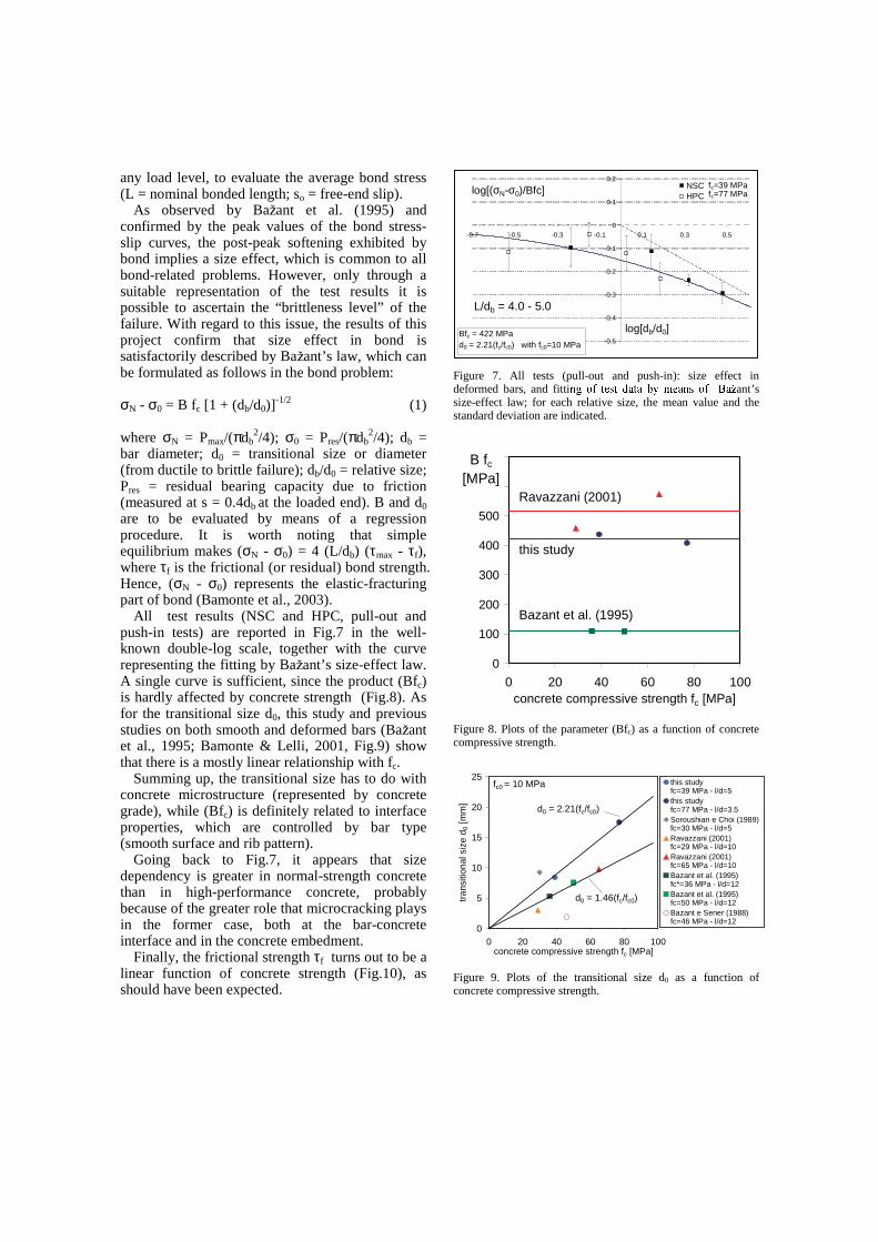
All test results (NSC and HPC, pull-out and push-in tests) are reported in Fig.7 in the well-known double-log scale, together with the curve representing the fitting by Baåant’s size-effect law. A single curve is sufficient, since the product (Bfc) is hardly affected by concrete strength (Fig.8). As for the transitional size d0, this study and previous studies on both smooth and deformed bars (Baåant et al., 1995; Bamonte & Lelli, 2001, Fig.9) show that there is a mostly linear relationship with fc.
Summing up, the transitional size has to do with concrete microstructure (represented by concrete grade), while (Bfc) is definitely related to interface properties, which are controlled by bar type (smooth surface and rib pattern).
Going back to Fig.7, it appears that size dependency is greater in normal-strength concrete than in high-performance concrete, probably because of the greater role that microcracking plays in the former case, both at the bar-concrete interface and in the concrete embedment.
Finally, the frictional strength τf turns out to be a linear function of concrete strength (Fig.10), as should have been expected.
-0.5
-0.4
-0.3
-0.2
-0.1
0
0.1
0.2
-0.7 -0.5 -0.3 -0.1 0.1 0.3 0.5
log[db/d0]
NSCHPC
Bfc = 422 MPad0 = 2.21(fc/fc0) with fc0=10 MPa
fc=39 MPafc=77 MPa
L/db = 4.0 - 5.0
log[(σN-σ0)/Bfc]
Figure 7. All tests (pull-out and push-in): size effect in deformed bars, and fitti ��������� ���� ���� ����������������������� ant’ s size-effect law; for each relative size, the mean value and the standard deviation are indicated.
0
100
200
300
400
500
600
700
0 20 40 60 80 100concrete compressive strength fc [MPa]
this study
Ravazzani (2001)
Bazant et al. (1995)
B fc
[MPa]
Figure 8. Plots of the parameter (Bfc) as a function of concrete compressive strength.
0
5
10
15
20
25
0 20 40 60 80 100concrete compressive strength fc [MPa]
tran
sitio
nal s
ize
d 0 [m
m]
this study fc=39 MPa - l/d=5this study fc=77 MPa - l/d=3.5Soroushian e Choi (1989)fc=30 MPa - l/d=5Ravazzani (2001) fc=29 MPa - l/d=10Ravazzani (2001) fc=65 MPa - l/d=10Bazant et al. (1995) fc*=36 MPa - l/d=12Bazant et al. (1995) fc=50 MPa - l/d=12Bazant e Sener (1988) fc=46 MPa - l/d=12
d0 = 2.21(fc/fc0)
fc0 = 10 MPa
d0 = 1.46(fc/fc0)
Figure 9. Plots of the transitional size d0 as a function of concrete compressive strength.
4 RADIAL CRACKING, BOND-INDUCED DILATANCY AND CONFINEMENT EFFECTS
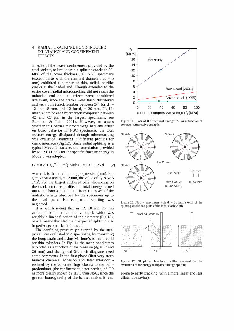
In spite of the heavy confinement provided by the steel jackets, to limit possible splitting cracks to 50-60% of the cover thickness, all NSC specimens (except those with the smallest diameter, db = 5 mm) exhibited a number of thin, radial, hairlike cracks at the loaded end. Though extended to the entire cover, radial microcracking did not reach the unloaded end and its effects were considered irrelevant, since the cracks were fairly distributed and very thin (crack number between 3-4 for db = 12 and 18 mm, and 12 for db = 26 mm, Fig.11; mean width of each microcrack comprised between 42 and 65 µm in the largest specimens, see Bamonte & Lelli, 2001). However, to assess whether this partial microcracking had any effect on bond behavior in NSC specimens, the total fracture energy dissipated through microcracking was evaluated, assuming 3 different profiles for crack interface (Fig.12). Since radial splitting is a typical Mode 1 fracture, the formulation provided by MC 90 (1990) for the specific fracture energy in Mode 1 was adopted: G� = 0.2 α� fcm
0.7 (J/m2) with α� = 10 + 1.25 d (2)
where da is the maximum aggregate size (mm). For fc = 39 MPa and da = 12 mm, the value of Gf is 62.6 J/m2. For the largest anchored bars, depending on the crack-interface profile, the total energy turned out to be from 4 to 11 J, i.e. from 1.2 to 4% of the inelastic energy absorbed by the specimens up to the load peak. Hence, partial splitting was neglected.
It is worth noting that in 12, 18 and 26 mm anchored bars, the cumulative crack width was roughly a linear function of the diameter (Fig.13), which means that also the unexpected splitting was in perfect geometric similitude!
The confining pressure p* exerted by the steel jacket was evaluated in 4 specimens, by measuring the hoop strain and using Mariotte’ s formula valid for thin cylinders. In Fig. 14 the mean bond stress is plotted as a function of the pressure (db = 12 and 26 mm) and the typical 3-branch diagrams need some comments. In the first phase (first very steep branch) chemical adhesion and later interlock - resisted by the concrete rings closest to the bar - predominate (the confinement is not needed, p* ≅ 0, as more clearly shown by HPC than NSC, since the greater homogeneity of the former makes it less
0
2
4
6
8
10
12
14
16
18
20
0 20 40 60 80 100
this study
Ravazzani (2001)
Bazant et al. (1995)
concrete compressive strength fc [MPa]
τf
[MPa]
Figure 10. Plots of the frictional strength τf as a function of concrete compressive strength.
ND4-BND4-A
ND4-C
4
7
10 4
7
10
1
4
7
10
Crack width:0.1 mm
Mean value: 0.054 mm
d = 26 mmb
(crack width)
Figure 11. NSC – Specimens with db = 26 mm: sketch of the splitting cracks and plots of the local crack width.
cracked interface
4db
L/4
L
4db 4db
Figure 12. Simplified interface profiles assumed in the evaluation of the energy dissipated through splitting. prone to early cracking, with a more linear and less dilatant behavior).
0.0
0.1
0.2
0.3
0.4
0.5
0.6
0.7
0.8
db (mm)
Σ w
i (m
m)
total crack width
mean number of cracks
5 12 18 26
Σwi = -0.3553 + 0.0376db
2
4
6
8
10
12
14
0
num
ber
of cra
cks
16
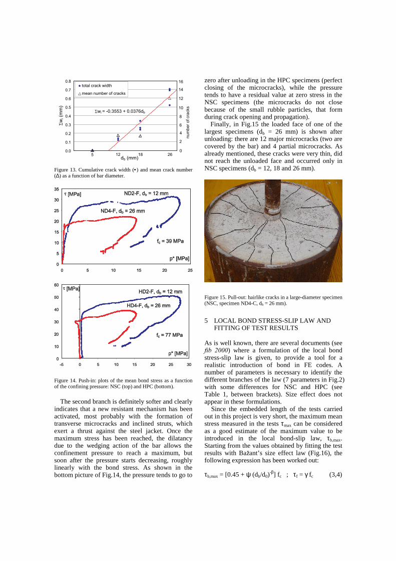
Figure 13. Cumulative crack width (•) and mean crack number (∆) as a function of bar diameter.
Figure 14. Push-in: plots of the mean bond stress as a function of the confining pressure: NSC (top) and HPC (bottom).
The second branch is definitely softer and clearly
indicates that a new resistant mechanism has been activated, most probably with the formation of transverse microcracks and inclined struts, which exert a thrust against the steel jacket. Once the maximum stress has been reached, the dilatancy due to the wedging action of the bar allows the confinement pressure to reach a maximum, but soon after the pressure starts decreasing, roughly linearly with the bond stress. As shown in the bottom picture of Fig.14, the pressure tends to go to
zero after unloading in the HPC specimens (perfect closing of the microcracks), while the pressure tends to have a residual value at zero stress in the NSC specimens (the microcracks do not close because of the small rubble particles, that form during crack opening and propagation).
Finally, in Fig.15 the loaded face of one of the largest specimens (db = 26 mm) is shown after unloading: there are 12 major microcracks (two are covered by the bar) and 4 partial microcracks. As already mentioned, these cracks were very thin, did not reach the unloaded face and occurred only in NSC specimens (db = 12, 18 and 26 mm).
Figure 15. Pull-out: hairlike cracks in a large-diameter specimen (NSC, specimen ND4-C, db = 26 mm).
5 LOCAL BOND STRESS-SLIP LAW AND FITTING OF TEST RESULTS
As is well known, there are several documents (see ILE� ����) where a formulation of the local bond stress-slip law is given, to provide a tool for a realistic introduction of bond in FE codes. A number of parameters is necessary to identify the different branches of the law (7 parameters in Fig.2) with some differences for NSC and HPC (see Table 1, between brackets). Size effect does not appear in these formulations. Since the embedded length of the tests carried out in this project is very short, the maximum mean stress measured in the tests τmax can be considered as a good estimate of the maximum value to be introduced in the local bond-slip law, τb,max. Starting from the values obtained by fitting the test results with Baåant’ s size effect law (Fig.16), the following expression has been worked out: τb,max = [0.45 + ψ (db/d0)
-β] fc ; τf = γ fc (3,4)
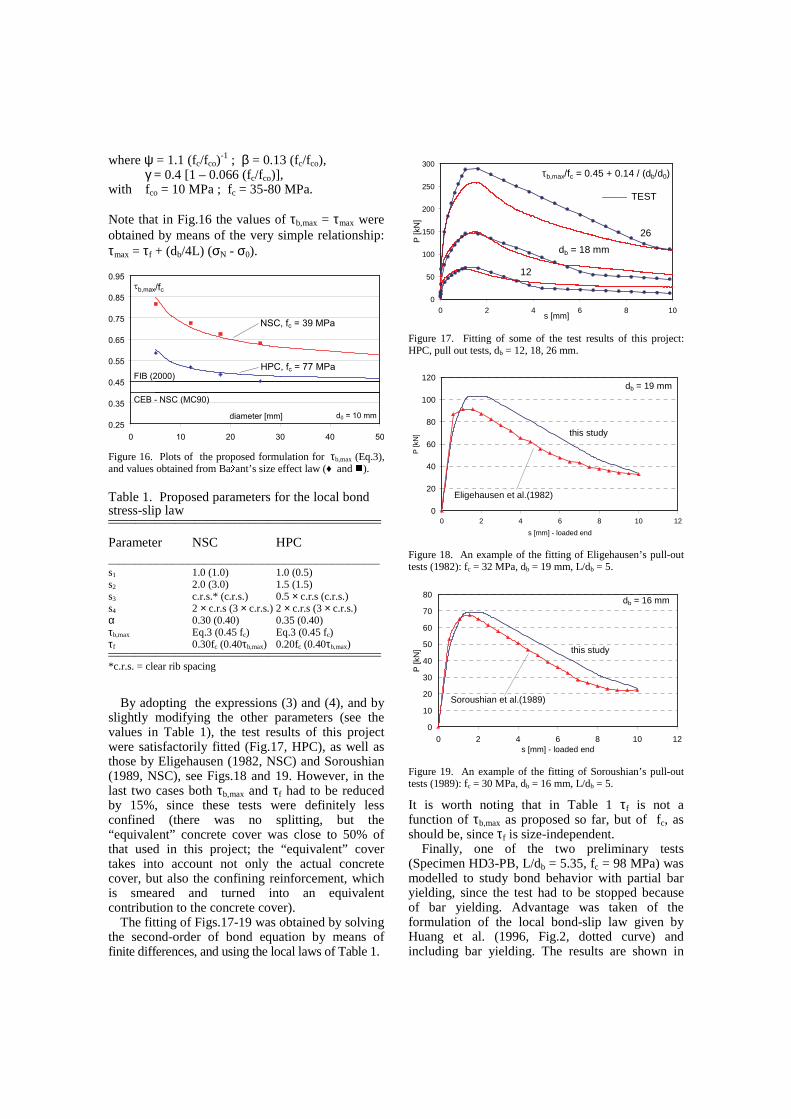
where ψ = 1.1 (fc/fco)-1 ; β = 0.13 (fc/fco),
γ = 0.4 [1 – 0.066 (fc/fco)], with fco = 10 MPa ; fc = 35-80 MPa. Note that in Fig.16 the values of τb,max = τmax were obtained by means of the very simple relationship: τmax = τf + (db/4L) (σN - σ0).
0.25
0.35
0.45
0.55
0.65
0.75
0.85
0.95
0 10 20 30 40 50
diameter [mm]
τb,max/fc
NSC, fc = 39 MPa
HPC, fc = 77 MPaFIB (2000)
CEB - NSC (MC90)
d0 = 10 mm
Figure 16. Plots of the proposed formulation for τb,max (Eq.3), and values obtained from Ba � ant’ s size effect law (♦ and � ).
Table 1. Proposed parameters for the local bond stress-slip law __________________________________________________________________________________
Parameter NSC HPC ___________________________________________________ s1 1.0 (1.0) 1.0 (0.5) s2 2.0 (3.0) 1.5 (1.5) s3 c.r.s.* (c.r.s.) 0.5 × c.r.s (c.r.s.) s4 2 × c.r.s (3 × c.r.s.) 2 × c.r.s (3 × c.r.s.) α 0.30 (0.40) 0.35 (0.40) τb,max Eq.3 (0.45 fc) Eq.3 (0.45 fc) τf 0.30fc (0.40τb,max) 0.20fc (0.40τb,max) __________________________________________________________________________________ *c.r.s. = clear rib spacing
By adopting the expressions (3) and (4), and by
slightly modifying the other parameters (see the values in Table 1), the test results of this project were satisfactorily fitted (Fig.17, HPC), as well as those by Eligehausen (1982, NSC) and Soroushian (1989, NSC), see Figs.18 and 19. However, in the last two cases both τb,max and τf had to be reduced by 15%, since these tests were definitely less confined (there was no splitting, but the “equivalent” concrete cover was close to 50% of that used in this project; the “equivalent” cover takes into account not only the actual concrete cover, but also the confining reinforcement, which is smeared and turned into an equivalent contribution to the concrete cover).
The fitting of Figs.17-19 was obtained by solving the second-order of bond equation by means of finite differences, and using the local laws of Table 1.
0
50
100
150
200
250
300
0 2 4 6 8 10s [mm]
P [k
N]
τb,max/fc = 0.45 + 0.14 / (db/d0)
TEST
db = 18 mm
26
12
Figure 17. Fitting of some of the test results of this project: HPC, pull out tests, db = 12, 18, 26 mm.
0
20
40
60
80
100
120
0 2 4 6 8 10 12
s [mm] - loaded end
P [k
N] this study
Eligehausen et al.(1982)
db = 19 mm
Figure 18. An example of the fitting of Eligehausen’ s pull-out tests (1982): fc = 32 MPa, db = 19 mm, L/db = 5.
0
10
20
30
40
50
60
70
80
0 2 4 6 8 10 12s [mm] - loaded end
P [k
N] this study
Soroushian et al.(1989)
db = 16 mm
Figure 19. An example of the fitting of Soroushian’ s pull-out tests (1989): fc = 30 MPa, db = 16 mm, L/db = 5.
It is worth noting that in Table 1 τf is not a function of τb,max as proposed so far, but of fc, as should be, since τf is size-independent. Finally, one of the two preliminary tests (Specimen HD3-PB, L/db = 5.35, fc = 98 MPa) was modelled to study bond behavior with partial bar yielding, since the test had to be stopped because of bar yielding. Advantage was taken of the formulation of the local bond-slip law given by Huang et al. (1996, Fig.2, dotted curve) and including bar yielding. The results are shown in
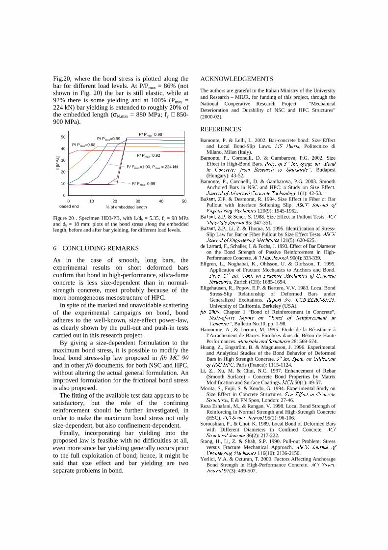
Fig.20, where the bond stress is plotted along the bar for different load levels. At P/Pmax = 86% (not shown in Fig. 20) the bar is still elastic, while at 92% there is some yielding and at 100% (Pmax = 224 kN) bar yielding is extended to roughly 20% of the embedded length (σN,max = 880 MPa; fy ≅ 850-900 MPa).
0
10
20
30
40
50
0 10 20 30 40 50
% of embedded length
τ [M
Pa]
loaded end
P/ Pmax=0.92
P/ Pmax=0.98
P/ Pmax=0.99
P/ Pmax=1.00, Pmax = 224 kN
P/ Pmax=0.99
P/ Pmax=0.98
Figure 20 . Specimen HD3-PB, with L/db = 5.35, fc = 98 MPa and db = 18 mm: plots of the bond stress along the embedded length, before and after bar yielding, for different load levels.
6 CONCLUDING REMARKS
As in the case of smooth, long bars, the experimental results on short deformed bars confirm that bond in high-performance, silica-fume concrete is less size-dependent than in normal-strength concrete, most probably because of the more homogeneous mesostructure of HPC. In spite of the marked and unavoidable scattering of the experimental campaigns on bond, bond adheres to the well-known, size-effect power-law, as clearly shown by the pull-out and push-in tests carried out in this research project. By giving a size-dependent formulation to the maximum bond stress, it is possible to modify the local bond stress-slip law proposed in ILE�0&� ���and in other ILE documents, for both NSC and HPC, without altering the actual general formulation. An improved formulation for the frictional bond stress is also proposed. The fitting of the available test data appears to be satisfactory, but the role of the confining reinforcement should be further investigated, in order to make the maximum bond stress not only size-dependent, but also confinement-dependent. Finally, incorporating bar yielding into the proposed law is feasible with no difficulties at all, even more since bar yielding generally occurs prior to the full exploitation of bond; hence, it might be said that size effect and bar yielding are two separate problems in bond.
ACKNOWLEDGEMENTS
The authors are grateful to the Italian Ministry of the University and Research – MIUR, for funding of this project, through the National Cooperative Research Project “ Mechanical Deterioration and Durability of NSC and HPC Structures” (2000-02). REFERENCES
Bamonte, P. & Lelli, L. 2002. Bar-concrete bond: Size Effect and Local Bond-Slip Laws. ����������� � , Politecnico di Milano, Milan (Italy).
Bamonte, P., Coronelli, D. & Gambarova, P.G. 2002. Size Effect in High-Bond Bars. �� ������� ����� ����� � �!��" #%$&�����(' )*�+��, �.-*�+�/�0 1��� ��23�+ ���#54���1�6� ����.� �7� � 6���,�6� 1,��!8 , Budapest (Hungary): 43-52.
Bamonte, P., Coronelli, D. & Gambarova, P.G. 2003. Smooth Anchored Bars in NSC and HPC: a Study on Size Effect. 9 ��:� ;��6/</� �&=>,�?6��/���0,@-*�+�/�0 1��� �A����0���/��< �+B�" 1(1): 42-53.
Ba C+D�E�F , Z.P. & Desmorat, R. 1994. Size Effect in Fiber or Bar Pullout with Interface Softening Slip. =>�/-�G 9 ��:� 1��6/<H� �G���B! ���0� 0 ��BI�J�+����6��K �0� 120(9): 1945-1962.
Ba C+D�E�F , Z.P. & Sener, S. 1988. Size Effect in Pullout Tests. =L-����6/� � � 6/< � 9 ��:� 1��6/< 85: 347-351.
Ba C+D�E�F , Z.P., Li, Z. & Thoma, M. 1995. Identification of Stress-Slip Law for Bar or Fiber Pullout by Size Effect Tests. =>� -�G9 ��:� ;��6/</� �MG���B! ���� 0 ��BI���+����6�� �0� 121(5): 620-625.
de Larrard, F., Schaller, I. & Fuchs, J. 1993. Effect of Bar Diameter on the Bond Strength of Passive Reinforcement in High-Performance Concrete. =>-%� �N6�� � 9 �+:+ ���6�< � 90(4): 333-339.
Elfgren, L., Noghabai, K., Ohlsson, U. & Olofsson, T. 1995. Application of Fracture Mechanics to Anchors and Bond. �� ����0�PO�Q �R� � � �I->�+� �+�I���TS� 16/�� :� 1�H�J�+�0��6��K �0�U� �T-*�����0 ;�+� �� � ;:��� :� 1�� , Zurich (CH): 1685-1694.
Eligehausen, R., Popov, E.P. & Bertero, V.V. 1983. Local Bond Stress-Slip Relationship of Deformed Bars under Generalized Excitations. 4�� $*�� ��HVP���XW*-�)%Y G�G�4*-*Z [��Y O/� , University of California, Berkeley (USA).
�� \(O ]�]�] . Chapter 1 “ Bond of Reinforcement in Concrete” ,� � 6 � �+Z � ��Z => ��^4�� $&�� ��_�+�`'�)&����,a� �b4��� � ���� ����#P��/�c �->�+�/�0 1��� ��8 , Bulletin No.10, pp. 1-98.
Hamouine, A., & Lorrain, M. 1995. Etude de la Résistance à l’ Arrachement de Barres Enrobées dans du Béton de Haute Performances. ��6/� � � 6/< ��6���,I�/� �:��+� :� 1�� 28: 569-574.
Huang, Z., Engström, B. & Magnusson, J. 1996. Experimental and Analytical Studies of the Bond Behavior of Deformed Bars in High Strength Concrete. ��d e�� � � � ��" #�$&�!�+�HW*� < f�6/� �+�� �LgP�/-�Y gP�&- , Paris (France): 1115-1124.
Li, Z., Xu, M. & Chui, N.C. 1997. Enhancement of Rebar (Smooth Surface) - Concrete Bond Properties by Matrix Modification and Surface Coatings. �h-�4 50(1): 49-57.
Morita, S., Fujii, S. & Kondo, G. 1994. Experimental Study on Size Effect in Concrete Structures. �K f��iG� �+��+�A �j->�+�/�0 1��� �� � ;:��� :� 1�� , E & FN Spon, London: 27-46.
Reza Eshafani, M., & Rangan, V. 1998. Local Bond Strength of Reinforcing in Normal Strength and High-Strength Concrete (HSC). =L-����/� �:��+� � 9 ��:� ;��6 < 95(2): 96-106.
Soroushian, P., & Choi, K. 1989. Local Bond of Deformed Bars with Different Diameters in Confined Concrete. =M-��� � ;:��� :� 16/< 9 ��:� ;��6/< 86(2): 217-222.
Stang, H., Li, Z. & Shah, S.P. 1990. Pull-out Problem: Stress versus Fracture Mechanical Approach. =*� -�G 9 ��:� 1��6/<U� �G���B! ���0� 0 ��BI�J�+����6��K �0� 116(10): 2136-2150.
Yerlici, V.A. & Ozturan, T. 2000. Factors Affecting Anchorage Bond Strength in High-Performance Concrete. =L-��N�/� �:��+� �9 ��:� ;��6/< 97(3): 499-507.


![Bond Behavior between Embedded Through-Section Bars and ... · E. Cosenza et al. [10] showed the three primary models of the bond behavior of FRP bars to concrete were the Eligehausen,](https://img.pdfslide.net/doc/110x75/60ae619c3162092d73364a6b/bond-behavior-between-embedded-through-section-bars-and-e-cosenza-et-al-10.jpg)