Embed Size (px)
Citation preview
AFRL-AFOSR-UK-TR-2010-0003
Development of Novel Skin Materials for Morphing Aircraft
Venkata P Potluri University of Manchester
School of Materials Sackville Street Building
Manchester, Greater Manchester United Kingdom M60 1QD
EOARD GRANT 083083
19 November 2010
Final Report for 15 September 2008 to 15 November 2010
Air Force Research Laboratory Air Force Office of Scientific Research
European Office of Aerospace Research and Development Unit 4515 Box 14, APO AE 09421
Distribution Statement A: Approved for public release distribution is unlimited.
REPORT DOCUMENTATION PAGE Form Approved OMB No. 0704-0188
Public reporting burden for this collection of information is estimated to average 1 hour per response, including the time for reviewing instructions, searching existing data sources, gathering and maintaining the data needed, and completing and reviewing the collection of information. Send comments regarding this burden estimate or any other aspect of this collection of information, including suggestions for reducing the burden, to Department of Defense, Washington Headquarters Services, Directorate for Information Operations and Reports (0704-0188), 1215 Jefferson Davis Highway, Suite 1204, Arlington, VA 22202-4302. Respondents should be aware that notwithstanding any other provision of law, no person shall be subject to any penalty for failing to comply with a collection of information if it does not display a currently valid OMB control number. PLEASE DO NOT RETURN YOUR FORM TO THE ABOVE ADDRESS. 1. REPORT DATE (DD-MM-YYYY)
19-11-2010 2. REPORT TYPE
Final Report 3. DATES COVERED (From – To)
15 September 2008 – 15 November 2010
4. TITLE AND SUBTITLE
Development of novel skin materials for morphing aircraft
5a. CONTRACT NUMBER FA8655-08-1-3083
5b. GRANT NUMBER
5c. PROGRAM ELEMENT NUMBER
6. AUTHOR(S)
Dr. Venkata P Potluri
5d. PROJECT NUMBER
5d. TASK NUMBER
5e. WORK UNIT NUMBER
7. PERFORMING ORGANIZATION NAME(S) AND ADDRESS(ES)University of Manchester Sackville street building Manchester M60 1QD United Kingdom
8. PERFORMING ORGANIZATION REPORT NUMBER
Grant 08-3083
9. SPONSORING/MONITORING AGENCY NAME(S) AND ADDRESS(ES)
EOARD Unit 4515 BOX 14 APO AE 09421
10. SPONSOR/MONITOR’S ACRONYM(S)
11. SPONSOR/MONITOR’S REPORT NUMBER(S)
AFRL-AFOSR-UK-TR-2010-0003 12. DISTRIBUTION/AVAILABILITY STATEMENT Approved for public release; distribution is unlimited. 13. SUPPLEMENTARY NOTES
14. ABSTRACT This project explored development of ‘skin’ material for morphing structures. Flexible fiber-reinforced composites are the prime candidates for morphing skins in order to achieve the required elongation and strength. Main objective was to develop a woven or cross ply fabric that can exhibit extension as well as shear deformations by developing and incorporating hyper-elastic yarns. These yarns consist of low modulus elastomeric core braided with high-modulus fibers. Low-modulus phase allows significant area change during deployment, and the high modulus stage provides the necessary stiffness to the skin after deployment. The ‘knee-point’ can be tuned to the desired strain necessary for the application by altering the manufacturing settings. In this work, two different hyper-elastic yarns were produced: biaxial braids and triaxial braids. Tensile testing showed the deformation processes to be similar. However, due to the style of interlacement, triaxial yarns achieved larger extensions. Both the styles of yarn are suitable for morphing skin applications. In addition, various braided yarns were developed by changing the pre-tension on the elastane yarn to produce different braid angles. The knee-point between low modulus and high modulus behavior was shown to shift based on braid angle, allowing a means of tuning the desired strain. A computational model for predicting the load-strain behavior of hyper-elastic yarns was developed and shown to agree well with experimental results. Finally, a woven composite was manufactured and tested as a morphing skin material using the braided yarns, and compared to analytical mechanics-based predictions.
15. SUBJECT TERMS EOARD, morphing structures, morphing skins
16. SECURITY CLASSIFICATION OF: 17. LIMITATION OF ABSTRACT
UL
18, NUMBER OF PAGES
22
19a. NAME OF RESPONSIBLE PERSONRandall Pollak, Lt Colonel, USAF a. REPORT
UNCLAS b. ABSTRACT
UNCLAS c. THIS PAGE
UNCLAS 19b. TELEPHONE NUMBER (Include area code) +44 (0)1895 616 115
Standard Form 298 (Rev. 8/98) Prescribed by ANSI Std. Z39-18

1
DEVELOPMENT OF MORPHING SKINS
Principal Investigator: Dr Prasad Potluri
Graduate student: Miss Sabahat Nawaz
Research Associates: Dr Haseeb Arshad, Dr Raj Ramgulam
AFRL co-ordinator: Dr Jeff Baur
Grant: FA8655-08-3083

2
DEVELOPMENT OF MORPHING SKINS Morphing Aircraft
A morphing aircraft can be defined as an aircraft that changes configuration to
maximize its performance at radically different flight conditions. These configuration
changes can take place in any part of the aircraft, e.g. fuselage, wing, engine, and tail.
Wing morphing is naturally the most important aspect of aircraft morphing as it
dictates the aircraft performance in a given flight condition, and has been of interest to
the aircraft designers since the beginning of the flight, progressing from the design of
control surfaces to the variable-sweep wing. Recent research efforts (mainly under
DARPA and NASA sponsorships) however, are focusing on even more dramatic
configuration changes such as 200% change in aspect ratio, 50% change in wing area,
5o change in wing twist, and 20o change in wing sweep to lay the ground work for
truly multi-mission aircraft. Such wing geometry and configuration changes, while
extremely challenging, can be conceptually achieved in a variety of ways – folding,
hiding, telescoping, expanding, and contracting a wing, coupling and decoupling
multiple wing segments.
Morphing structures require a large aspect ratio and area change during flight in order
to optimise operational performance. Following are the key elements of a morphing
wing concept:
� Skeleton: a spatial kinematic linkage for achieving desired wing
configurations by folding, telescoping, expanding or contracting
� Actuators for configuration change
� Skin: To provide an aerodynamic surface free from wrinkles by
accommodate large surface area changes.
� Means of rigidizing the skin
This project focuses on the development of ‘skin’ material. Key Requirements for the
skin material are:
� Large area change
� Smooth aerodynamic surface, free from wrinkles
� Low creep under tension
� Low hysteresis in extension

3
� Convenient method of joining to the skeleton
� Suitable means of integration of digitization elements
Shear vs extensional modes Flexible fibre reinforced composites are the prime candidates for morphing skins in
order to achieve the required elongation and strength. There are two principal
methods of achieving area change in an elastic membrane, shear mode and
extensional mode. A biaxial fibre architecture, woven or cross-ply, exhibits reduction
in surface area when deformed in shear - deformation along the yarn directions is
insignificant (figure 1a). A knitted architecture (figure 1b) exhibits increase in
surface area when stretched in principal and bias directions. However, knitted fabrics
have limitations: limited range of elongations, significant knockdown in strength due
to sharp curvatures, and difficulty in knitting high modulus yarns.
.
Figure 1: a) Shear mode b) extension mode

4
Concept of biaxial fabrics for extension mode Main objective of this research is to develop a woven or cross ply fabric that can
exhibit extension as well as shear deformations. This concept requires the
development of hyper-elastic yarns.
Figure 2: concept of hyper-elastic yarns
The concept of hyper-elastic yarns is shown in figure2. These yarns consist of low-
modulus elastomeric core braided around with high-modulus fibres. Expected force-
strain behaviour is as shown in figure 3. Low-modulus phase allows significant area
change during deployment, and the high modulus stage provides the necessary
stiffness to the skin after deployment. The ‘knee-point’ can be tuned to the required
strain (by altering the manufacturing process).
Figure 3: Force-strain behaviour of hyper-elastic yarns
Force
Strain
Knee point Low modulus
High modulus
5
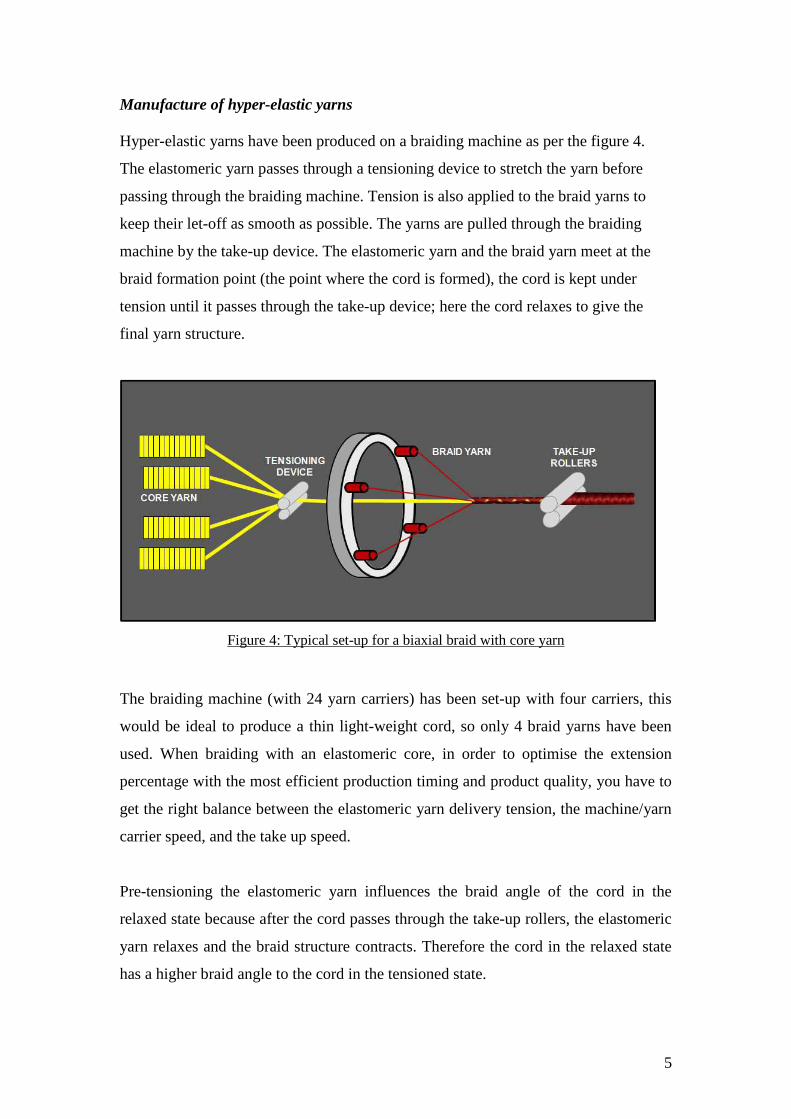
Manufacture of hyper-elastic yarns Hyper-elastic yarns have been produced on a braiding machine as per the figure 4.
The elastomeric yarn passes through a tensioning device to stretch the yarn before
passing through the braiding machine. Tension is also applied to the braid yarns to
keep their let-off as smooth as possible. The yarns are pulled through the braiding
machine by the take-up device. The elastomeric yarn and the braid yarn meet at the
braid formation point (the point where the cord is formed), the cord is kept under
tension until it passes through the take-up device; here the cord relaxes to give the
final yarn structure.
Figure 4: Typical set-up for a biaxial braid with core yarn
The braiding machine (with 24 yarn carriers) has been set-up with four carriers, this
would be ideal to produce a thin light-weight cord, so only 4 braid yarns have been
used. When braiding with an elastomeric core, in order to optimise the extension
percentage with the most efficient production timing and product quality, you have to
get the right balance between the elastomeric yarn delivery tension, the machine/yarn
carrier speed, and the take up speed.
Pre-tensioning the elastomeric yarn influences the braid angle of the cord in the
relaxed state because after the cord passes through the take-up rollers, the elastomeric
yarn relaxes and the braid structure contracts. Therefore the cord in the relaxed state
has a higher braid angle to the cord in the tensioned state.

6
Figure 5: Cord during braiding in tensioned state vs. Cord in the relaxed state
The braid angle
Figure 6: braid angle The braid angle is the orientation of the yarns from the braid axis (figure6). Braid
angle can be measured using image analysis. When extending a braided structure
there is a kinematic rotation of reinforcing yarn as shown in figure 7. As the braided
structure is pulled, the braid angle (θ) decreases, but the length of the wrap yarn (l0)
stays the same. However, the length of the braid increases from an initial length (l1) to
the extended position (l2). But there is a limit to the amount which the braid can
extend because the braid will eventually reach a ‘jamming position’ where the yarns
will lock. Therefore maximum strain achieved by a braided yarn depends on the initial
braid angle.
Braid Angle
Braid Axis

7
Figure 7: kinematic rotation of braided structure
In this work, two different hyper-elastic yarns were produced: 1) biaxial braids and 2)
triaxial braids.
The biaxial elastomeric braid consists of 4 elastane yarns as the core and 4 Kevlar
yarns for interlacing around the core yarns. Elastane yarns are passed through the
centre of the braiding machine and the braid yarns intertwine around them, creating an
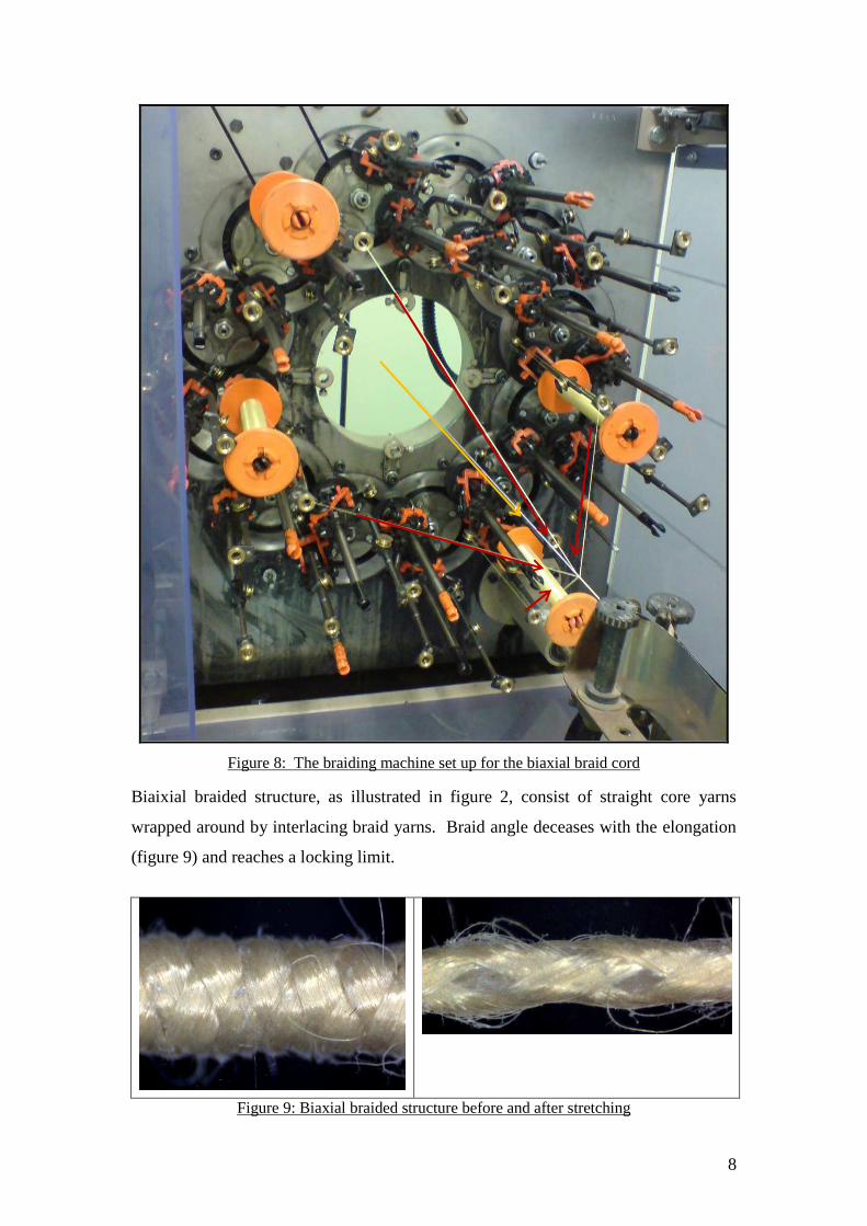
overwrap of the braid yarns, placing the elastane in the centre. Figure 8 shows the
braiding machine set-up for biaxial braids. It can be seen that the elastane core yarns
pass through the centre of the machine, and the four Kevlar yarn bobbins are mounted
on carriers that rotate on a track. Two of the carriers rotate in clock-wise direction
interlacing with the two yarn carriers rotating in anti clock-wise direction.
θ
1
θ
l0 l0
l2 l1
8
Figure 8: The braiding machine set up for the biaxial braid cord
Biaixial braided structure, as illustrated in figure 2, consist of straight core yarns
wrapped around by interlacing braid yarns. Braid angle deceases with the elongation
(figure 9) and reaches a locking limit.
Figure 9: Biaxial braided structure before and after stretching
9
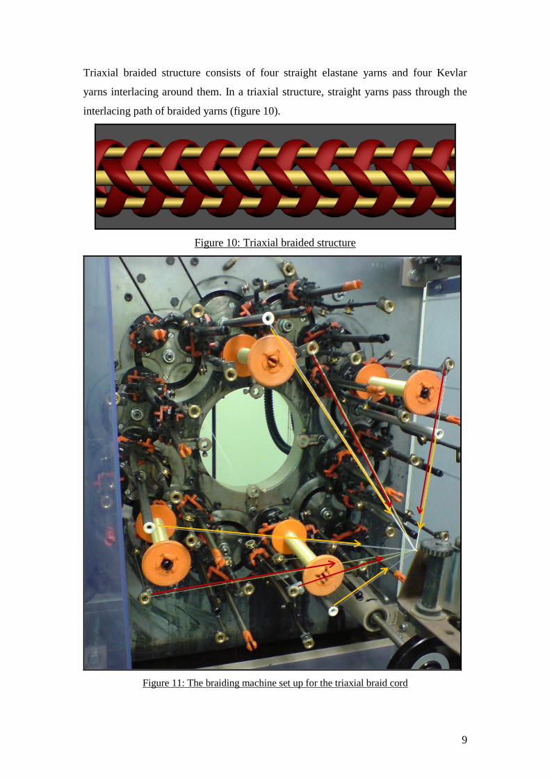
Triaxial braided structure consists of four straight elastane yarns and four Kevlar
yarns interlacing around them. In a triaxial structure, straight yarns pass through the
interlacing path of braided yarns (figure 10).
Figure 10: Triaxial braided structure
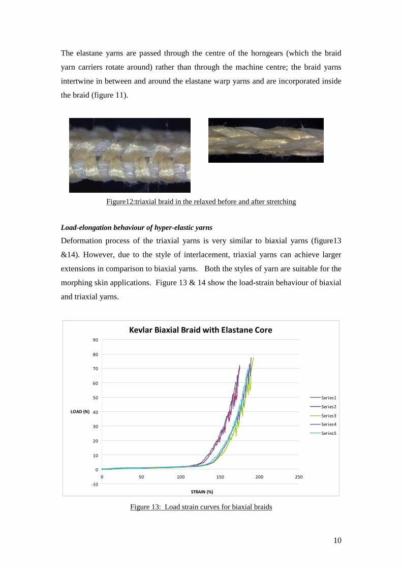
Figure 11: The braiding machine set up for the triaxial braid cord
10
The elastane yarns are passed through the centre of the horngears (which the braid
yarn carriers rotate around) rather than through the machine centre; the braid yarns
intertwine in between and around the elastane warp yarns and are incorporated inside
the braid (figure 11).
Figure12:triaxial braid in the relaxed before and after stretching
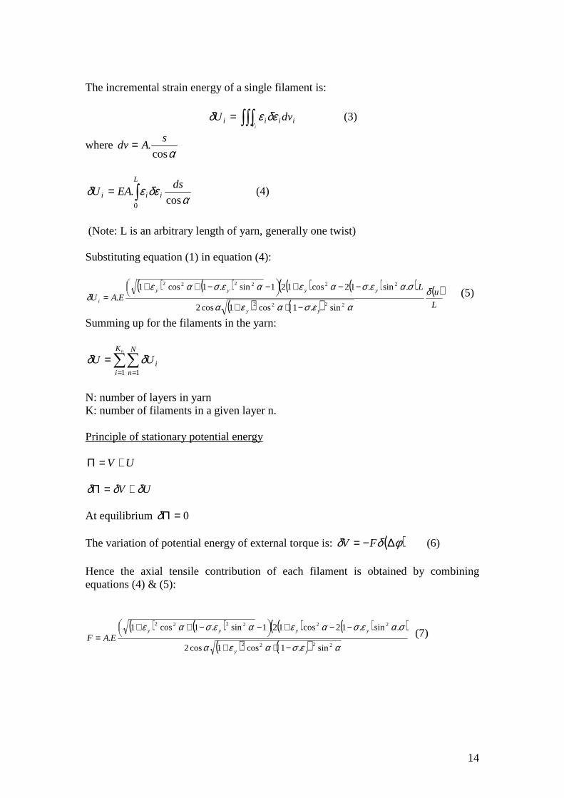
Load-elongation behaviour of hyper-elastic yarns
Deformation process of the triaxial yarns is very similar to biaxial yarns (figure13
&14). However, due to the style of interlacement, triaxial yarns can achieve larger
extensions in comparison to biaxial yarns. Both the styles of yarn are suitable for the
morphing skin applications. Figure 13 & 14 show the load-strain behaviour of biaxial
and triaxial yarns.
Kevlar Biaxial Braid with Elastane Core
-10
0
10
20
30
40
50
60
70
80
90
0 50 100 150 200 250
STRAIN (%)
LOAD (N)
Series1
Series2
Series3
Series4
Series5
Figure 13: Load strain curves for biaxial braids

11
Kevlar Triaxial Braid with Elastane Warp Yarns
-10
0
10
20
30
40
50
60
70
80
90
100
0 50 100 150 200 250 300 350 400
STRAIN (%)
LOAD (N)
Series1
Series3
Series4
Series5
Figure 14: Load-strain curves for triaxial braids
Development of braided yarns with different strain limits Four different braided yarns were developed (by changing the pre-tension on the elastane yarn)
with different braid angles.
Braid Initial braid angle Braid angle at the
knee Max strain %
Braid 1 29 27 22
Braid 2 38 27 49
Braid 3
52 27 89
Braid 4 73 27 254
Table 1: Relation between initial braid angle and maximum strain
It can be seen from figure 15 that the knee point on the graph can be shifted by changing the
braid angle. Hence, it is possible to design a yarn with required load-strain relationship for a
given state of deployment (of the morphing structure).

12
Load-strain curves for different braid angles
0
10
20
30
40
50
60
70
80
90
0 50 100 150 200 250 300
Strain (%)
Loa
d (
N)
Braid 1
Braid 2
Braid 3
Braid 4
Figure 15: Load-strain relationship of braids with different braid angles
Modelling the load-elongation behaviour of hyper-elastic yarns A computational model for predicting the load-strain behaviour of hyper-elastic yarns
has been developed. The model is based on the principle of virtual work. The inputs
to the model are:
• Stress-strain behaviour of elastane yarn
• Stress-strain behaviour of Kevlar yarn
• Yarn twist angle calculated from braid angle and core diameter
• Load-elongation characteristic of the filaments
• Poisson’s ratio of the yarns
Load-strain behaviour of hyper-elastic braided yarns may be divided into three stages:
Stage 1: low-modulus stage is dominated by elastane yarns. Kevlar yarns are
subjected to kinematic rotation up to the knee point without significant contribution to
the load/stress.
13
Yarn strain at the knee point can be computed using equation (1) based on kinematic
rotations.
( )1
1
coscoscos
θθθε −= knee
knee (1)
Force generated in the yarn is a function of elastane stress-strain curve.
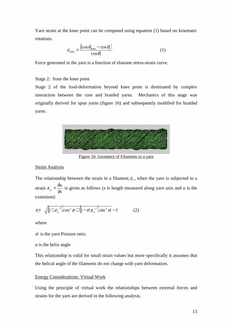
Stage 2: from the knee point
Stage 2 of the load-deformation beyond knee point is dominated by complex
interaction between the core and braided yarns. Mechanics of this stage was
originally derived for spun yarns (figure 16) and subsequently modified for braided
yarns.
Figure 16: Geometry of Filaments in a yarn
Strain Analysis The relationship between the strain in a filament,iε , when the yarn is subjected to a
strain s
uy ∂
∂=ε is given as follows (s is length measured along yarn axis and u is the
extension):
( ) ( ) 1sin..1cos1 2222 −−++= αεσαεε yyi (2)
where σ is the yarn Poisson ratio. α is the helix angle This relationship is valid for small strain values but more specifically it assumes that
the helical angle of the filaments do not change with yarn deformation.
Energy Considerations: Virtual Work Using the principle of virtual work the relationships between external forces and
strains for the yarn are derived in the following analysis.
14
The incremental strain energy of a single filament is:
iv iii dvUi
∫∫∫= δεεδ (3)
where αcos
.s
Adv =
αδεεδ
cos.0
dsEAU i
L
ii ∫= (4)
(Note: L is an arbitrary length of yarn, generally one twist) Substituting equation (1) in equation (4):
( ) ( ) ( ) ( )( )( ) ( )
( )L
uL
EAUyy
yyyy
i
δ
αεσαεα
σαεσαεαεσαεδ
2222
222222
sin.1cos1cos2
..sin.12cos121sin.1cos1.
−++
−−+
−−++
= (5)
Summing up for the filaments in the yarn:
∑∑= =
=nK
i
N
niUU
1 1
δδ
N: number of layers in yarn K: number of filaments in a given layer n. Principle of stationary potential energy
UV +=Π
UV δδδ +=Π At equilibrium 0=Πδ The variation of potential energy of external torque is: ( )φδδ ∆−= FV (6) Hence the axial tensile contribution of each filament is obtained by combining equations (4) & (5):
( ) ( ) ( ) ( )( )( ) ( ) αεσαεα
σαεσαεαεσαε
2222
222222
sin.1cos1cos2
.sin.12cos121sin.1cos1.
yy
yyyy
EAF−++
−−+
−−++
= (7)

15
The tensile contribution for each filament has to be added to obtain the tension/strain
relationship for the whole yarn. Figure 17 presents the computed load-strain
behaviour of four braided yarns (produced with different braid angles). These curves
compare favourably with the experimental curves presented in figure 15.
0
10
20
30
40
50
60
70
80
90
100
0 50 100 150 200 250
Strain %
Lo
ad (N
)
Yarn1
yarn2
yarn3
Yarn 4
Figure 17: computed load-strain curves for hyper-elastic yarns
Computational model used in the present work for predicting the load-strain
behaviour of the yarns is a useful tool in developing hyper-elastic yarns for specific
extensibility.
16
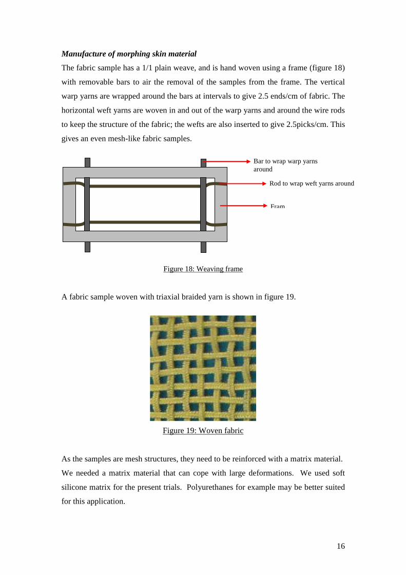
Manufacture of morphing skin material
The fabric sample has a 1/1 plain weave, and is hand woven using a frame (figure 18)
with removable bars to air the removal of the samples from the frame. The vertical
warp yarns are wrapped around the bars at intervals to give 2.5 ends/cm of fabric. The
horizontal weft yarns are woven in and out of the warp yarns and around the wire rods
to keep the structure of the fabric; the wefts are also inserted to give 2.5picks/cm. This
gives an even mesh-like fabric samples.
Figure 18: Weaving frame A fabric sample woven with triaxial braided yarn is shown in figure 19.
Figure 19: Woven fabric
As the samples are mesh structures, they need to be reinforced with a matrix material.
We needed a matrix material that can cope with large deformations. We used soft
silicone matrix for the present trials. Polyurethanes for example may be better suited
for this application.
Rod to wrap weft yarns around
Fram
Bar to wrap warp yarns around
17
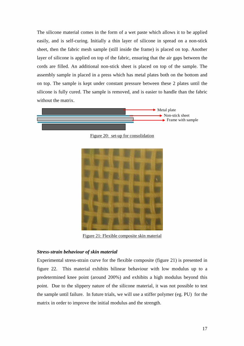
The silicone material comes in the form of a wet paste which allows it to be applied
easily, and is self-curing. Initially a thin layer of silicone in spread on a non-stick
sheet, then the fabric mesh sample (still inside the frame) is placed on top. Another
layer of silicone is applied on top of the fabric, ensuring that the air gaps between the
cords are filled. An additional non-stick sheet is placed on top of the sample. The
assembly sample in placed in a press which has metal plates both on the bottom and
on top. The sample is kept under constant pressure between these 2 plates until the
silicone is fully cured. The sample is removed, and is easier to handle than the fabric
without the matrix.
Figure 20: set-up for consolidation
Figure 21: Flexible composite skin material
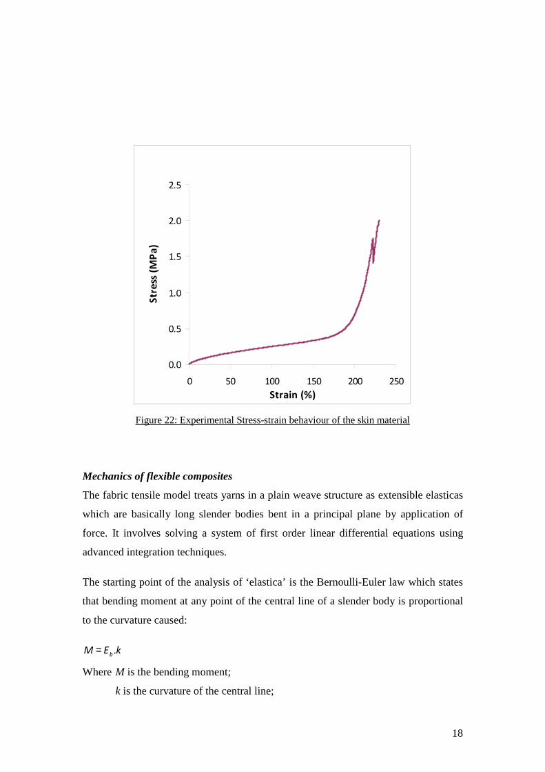
Stress-strain behaviour of skin material
Experimental stress-strain curve for the flexible composite (figure 21) is presented in
figure 22. This material exhibits bilinear behaviour with low modulus up to a
predetermined knee point (around 200%) and exhibits a high modulus beyond this
point. Due to the slippery nature of the silicone material, it was not possible to test
the sample until failure. In future trials, we will use a stiffer polymer (eg. PU) for the
matrix in order to improve the initial modulus and the strength.
Non-stick sheet Frame with sample
Metal plate
18
0.0
0.5
1.0
1.5
2.0
2.5
0 50 100 150 200 250
Strain (%)
Str
ess
(M
Pa
)
Figure 22: Experimental Stress-strain behaviour of the skin material
Mechanics of flexible composites
The fabric tensile model treats yarns in a plain weave structure as extensible elasticas
which are basically long slender bodies bent in a principal plane by application of
force. It involves solving a system of first order linear differential equations using
advanced integration techniques.
The starting point of the analysis of ‘elastica’ is the Bernoulli-Euler law which states
that bending moment at any point of the central line of a slender body is proportional
to the curvature caused:
kEMb.=
Where M is the bending moment;
k is the curvature of the central line;

19
Eb is the bending rigidity.
The equilibrium of forces on an element of a yarn within a unit repeat can be
considered. These forces result when a stretching (tensile) force P is applied. 2Q is
the resultant of the reaction forces from crossing threads.
P P
2Q
2Q
y
x θ
s
P
Q
P
Q
M
M
Figure 23 Equilibrium of forces on yarn element within unit repeat
Moment equilibrium gives the following differential equation:
02
2
=−+ θθθcos.sin. QP
ds
dEb
where, s is the length of the centre line of the deformed elastica, thus curvature is ds
dθ
Measured yarn properties and dimensions, and geometric parameters relating to the
fabric structure are used as inputs. These include: fabric sett, yarn crimp, number of
filaments per yarn, and minimum & maximum yarn diameters. The rate of change of
modulus with strain and the failure load are computed from experimental data relating
yarn tensile stress and strain. Fabric tensile load-extension is simulated as an output.
The model also incorporate simple rule of mixture for incorporating matrix properties
into mechanics of flexible woven fabric. Figure 24 compares the predicted stress-
strain behaviour with the experimental curve. Experimental knee point is somewhat
smaller than the computed – the difference is primarily due to reduced mobility of
Kevlar yarn inside the matrix. Figure 25 shows the influence of matrix stiffness on
the stress-strain behaviour. It is possible to tune the initial modulus, knee position,
final modulus and strength of the flexible skin material.

20
0.0
0.5
1.0
1.5
2.0
2.5
3.0
0 50 100 150 200 250 300
Strain (%)
Str
ess
(M
Pa
)
Experimental
Simulated (Sil icone matrix, E=0.16 N/mm2)
Figure 24: predicted versus experimental stress-strain curve
0.0
0.5
1.0
1.5
2.0
2.5
3.0
3.5
4.0
0 50 100 150 200 250 300
Strain (%)
Str
ess
(M
Pa
)
E=0.15N/mm2
E=0.30N/mm2
E=0.45N/mm2
E=0.60N/mm2
Figure 25: Influence of matrix stiffness on the stress-strain behaviour