Embed Size (px)
Citation preview

FurukawaReview,No.39 2011 6
* FitelPhotonicsLaboratoryR&DDiv.
1. INTRODUCTION
The polarization-multiplexed quadrature phase-shift key-ingtransmissionsystemcombinedwiththedigitalsignalprocessing shows great promise as the next-generationtransmission system with the bit-rate higher than100 Gbit/s in one channel. Especially, the DP-QPSK isrecognized as a standard format in 100 Gbit/s Ethernetsystems, and related specifications for transmitters andreceivers are standardized in Optical InternetworkingForum(OIF) 3).Amongthem,thespecificationsofanopti-cal receiver front-endhavebeendeveloped,whichcom-prise a PBS, 90-degree hybrid mixers, balanced photodetectors(BPDs)andtransimpedanceamplifiersinasin-gle module, and plays the roles of splitting the multi-plexed polarizations , demodulating a phase-modulatedoptical signal, and converting the optical signal to theelectrical one. In a front-end module, the PBS and the90-degreehybridmixersarerequiredtobesmallsothattheycanbepackagedinthespecifiedsizeofthemodule.Inaddition,opticalfeaturessuchaslowloss,highaccura-cy,andstabilityaredesired for thedevices.Finally, theyshould be capable of mass-production at low cost. Torealizeaproductwhich satisfies these requirements,weinvestigated thedevelopmentof theopticalcircuitwhichintegrated the PBS and the 90-degree hybrid mixer in aplanarlightwavecircuit 4) ~ 6).Thisreportshowsthespecificdevelopmentresults.
InSection2,weproposeaPLCintegratingaPBScon-sistingofcascadedMach-Zehnderinterferometers(MZIs)
and 90-degree hybrid mixers, where the polarization-extinction ratio for thedual-polarizationoptical signals isdrasticallyimproved.
Section 3 focuses on downsizing of a PBS-integratedcoherent mixer chip, and shows a fabrication result ofultra-small PLC chip with the dimension of 12 mm×12 mm. To downsize the chip dimension, we increasetheΔofawaveguideto1.8%inthePLCfabricatingpro-cess,anddevelopthecircuit layoutof foldedwaveguideconfiguration.
2. DEVELOPMENTOFTHEDOUBLE-PASSPBS-INTEGRATEDCOHERENTMIXER
Both thestableoperationand thedownsizingarepossi-ble by applying a PLC to passive optical componentssuchasPBSand90-degreehybridmixer.Infact,variousexperimental results are reported 7) ~ 9). Combining thesetechnologies, a PLC which has a PBS and a 90-degreehybrid mixer integrated in one chip is proposed 10).Reference10)reportsthatthePBScomprisedofasingleMZIhasthePERofapproximately25dB.Inthissection,fordesignofPBS-integratedcoherentmixer,weproposetocomposeaPBSofadouble-passcascaded-typeMZItoimprovethePERofpolarization-multiplexedopticalsig-nal 9).
ABSTRACTAsilica-basedplanarlightwavecircuit(PLC)thatisrequiredforareceiverfront-end used in digital coherent telecommunication system is developed by
integrating a polarization-beam splitter (PBS) and a 90-degree hybrid mixer. At first, byconfiguringaPBSforsignalwithadouble-passMach-Zehnderinterferometer,aPBS-integratedcoherentmixerchipisdevelopedandapolarizationextinctionratio(PER)higherthan30dBisachieved.Inthenextstage,downsizingofaPLCchipisstudied.Forthispurpose,therelativerefractive index differenceΔ is improved to 1.8%, and a circuit layout of folded waveguide isemployed. As a result, an ultra-small PBS integrated mixer chip with dimension of12mm×12mmisrealized.Using the developed chips in digital coherent receivers, experiments to demodulate dual-polarization quadrature phase-shift keying (DP-QPSK) signals at 40 Gbit/s and 100 Gbit/s areconducted,andexcellentperformanceswereconfirmedinbothcases.
DevelopmentofPBS-IntegratedCoherentMixerUsingSilica-BasedPlanarLightwaveCircuit
Takashi Inoue*, Hiroshi Kawashima*, Noritaka Matsubara*, and Kazutaka Nara*

Development of PBS-Integrated Coherent Mixer Using Silica-Based Planar Lightwave Circuit
FurukawaReview,No.39 2011 7
(a)
HWP
TE
TM
TM
TM
Signal(TE/TM)
LO(TM)
TE
TM
Outputport #1234
5678
Δθ = 90deg.
PBS (1st stage)PBS (2nd stage) for TE-signal
PBS (2nd stage) for TM-signal
Upper mixer for TE-signal
Lower mixer for TM-signal
Δθ = 90deg.
(b)
Figure1 (a)Schematicdiagramoftheproposeddouble-passPBS-integratedcoherentmixerbasedonPLC,and(b)pictureofafabricatedPLC-chip.
Figure 1(a) shows a schematic diagram of the circuitlayoutoftheproposedPLCchip.Theinputsignalpropa-gates through the first stage PBS and the signal is splitinto theTEand theTMpolarizations.The secondstagePBSimprovesthePERof theTE/TMsignals.Wenote inFigure 1(a) that the waveguides after the first- and sec-ond-stage double-pass Mach-Zehnder PBSs are folded,whichcontributestoasignificantdownsizingofthelongi-tudinaldimensionofthechip.
Between the second PBS and the mixer for theTE-signal, a half-wave plate (HWP) with 45-degreeinclinedprincipalaxisisinserted.Andthen,theTE-signalof the optical signal is converted to the TM-mode andinjected intotheuppermixerof thechip.Meanwhile, theTM polarization component of the optical signal afterpropagating throughthePBS isdirectly injected into thelower mixer of the chip without any polarization conver-sion.
Ontheotherhand,thelocaloscillator(LO)withtheTMpolarization is injected into the PLC and guided to theupper and the lower90-degreehybridmixersafter split-ting. The split LOs interfere with the optical signals atupper and lower mixers and are emitted from the eightoutputportsofthePLC.ThelightsemittedfromthePLCchipareinjectedintofourBPDsthroughfree-spaceopticsoropticalfibers.
Figure1(b)showsapictureof the fabricatedchipwiththedimensionof25mm×21mm.Themaximuminsertionloss between the input port and the output port is10.1dB:thisincludesthe6dBoftheintrinsiclossofthe90-degreehybridmixerandthebondinglossassociatedwith the optical fibers used for the loss evaluation. In a
similarway,themaximuminsertionlossbetweenLOandeachoutputportis11.6dB:thisincludesthe3dBoftheintrinsiclossofthepowersplitter,9dBoftheintrinsiclossofthe90-degreehybridmixerandthebondinglossasso-ciated with the input and the output optical fibers. TheminimumPERof theoptical signalpasses is33.2dBat1.55 μm. An extremely large PER is obtained thanks tothedouble–passcascaded-MZIstructureforthePBS.
In order to evaluate the phase characteristics of a90-degreehybridmixer,weconfigureMZIscombiningthemixerwithanextraPLCchipconsistingofasingle inputwaveguide,abeamsplitter,and twoopticalpaths led totheoutputwithdifferentlengths.Noteherethatweadjustthepath-lengthdifferencesothattheMZIshavethesinu-soidal interference pattern in the frequency domain withthefree-spectralrange(FSR)of100GHz.Figure2showsthe“MZIintensitytransferfunctionvs.thewavelength”oftheupperand the lowermixers.Fromthismeasurementresult, we confirm that the upper and lower mixers welloperateas90-degreeopticalhybridmixers.
Spe
ctru
m (
a.u.
)
1551 1551.5 1552 1552.5 1553
Wavelength (nm)
Spe
ctru
m (
a.u.
)Port#1234
Port#
678
5
Figure 2 The interference patterns of MZIs comprising the integrated coherent mixers.
We conduct a transmission experiment of a 40-Gbit/sDP-QPSK signal using the fabricated PLC chip shownabove in a digital coherent receiver. Figure 3 shows theexperimentalsetup.Thewavelengthof theopticalsignaland the local oscillator was 1552 nm. A 200-km singlemodefiber(SMF)wasusedforthetransmissionline.Thedeveloped double-pass PBS-integrated coherent mixerwas allocated in front of the BPDs in the receiver, andoptical fibers were used to connect the PLC and theBPDs. In this experiment, instead of using the HWPshowninFigure1(a),theinputLOwasadjustedtocon-tainthesameopticalpowerforbothoftheTE/TMmodes.In this case, the optical demodulation operation workswell, though the optical loss for LO has been increasedby3dB.

Development of PBS-Integrated Coherent Mixer Using Silica-Based Planar Lightwave Circuit
FurukawaReview,No.39 2011 8
DFB-LD: Distributed-feedback laser diodeIQM: IQ modulatorPPG: Pulse pattern generatorPBS: Polarization-beam splitterPBC: Polarization-beam combinerEDFA: Erbium-doped fiber amplifier
SMF: Single-mode fiberVOA: Variable optical attenuatorLO: Local oscillatorBPD: Balanced photo detectorADC: Analog-to-digital converterDSP: Digital signal processing
Optical lineElectrical line
IQM
PPG
ADCDSPcircuit
(Offline)
PLC-basedcoherent mixerw/double-pass
PBS
ADC
EDFA
EDFA VOA
ADC
ADC
BPD
BPD
BPD
BPD
PBS PBC
SMF200 km
40 Gbit/sQPSK
DFB-LD (LO)
DFB-LD
Figure 3 The setup for the 40-Gbit/s DP-QPSK signal transmission experiment.
(a) TE signal
-37 dBm, B-to-B-27 dBm, B-to-B -37 dBm, after 200 km
-37 dBm, B-to-B-27 dBm, B-to-B -37 dBm, after 200 km
(b) TM signal
Figure 4 The constellation maps of back-to-back (B-to-B) and transmitted DP-QPSK signals.
-50 -45 -40 -35Received power (dBm)
BE
R
10 -1
10-2
10-3
10-6
10-4
10-5
Back-to-back (TM)Back-to-back (TE)After 200 km (TM)After 200 km (TE)Shot-noise limit
Figure 5 BER characteristics of 40-Gbit/s DP-QPSK signals.
Figure4shows theconstellationmapsof the received40-Gbit/s DP-QPSK signals at back-to-back and after a200-km transmission. In Figure 4, clear constellationmaps are observed for both the TE/TM modes of thepolarization-demultiplexedsignal.Figure5showsthebit-error rate (BER) characteristics. The BER is observedeven for the signal transmitted over the long distance,and the satisfactory performance of the developed PLCasacomponentinacoherentreceiverisconfirmed.
3. DEVELOPMENTOFANULTRASMALLPBS-INTEGRATEDCOHERENTMIXERUSING1.8%ΔPROCESS
The chip dimension of the double-pass PBS-integratedcoherentmixerwhich is reported in theprevioussectionis 25 mm×21 mm. In consideration of the practicalaspect,amorecompactdimensionisrequired.Inparticu-lar, for use with enough room in the receiver front-endmodulestandardizedbyOIF 11),adimensionof less than15mmsquareisdesired.
Inthissection,developmentofasignificantdownsizingofthechipisinvestigated.Forthispurpose,weimproveaPLCfabricationprocesswithahigherΔsothatthebend-ingradiusof thewaveguide is reducedandthusacom-pactcircuit layoutcanbedesigned. In theprevioussec-tion, thePBSwith thedouble-passMZIstructure is inte-gratedonlyforthesignal,andnotfortheLO.Ontheotherhand, in this section, we develop a PLC chip that inte-grates PBSs for both the signal and the LO, and90-degreehybridmixers.
First,Δ of the waveguide is optimised. Generally, ahigherΔmakestheopticalconfinementofaguidedmodestronger and the bending radius of the waveguide canthenbe reduced.Figure6(a) shows thecalculatedmini-mum bending radius of the silica-based PLC forΔ. Theminimumbending radius ismonotonicallydecreased foran increasedΔ.TherelationbetweenΔandthethermal-expansioncoefficientαoftheSiO2-GeO2glassisshowninFigure6(b),whereαincreaseswithΔ.IntherangewhereΔ>2.5%,αoftheglassexceedsthatofthesiliconsub-strate. In this range, a tensile stress is induced in theglassandthereliabilityofthecoreglassisseverelydeteri-orated. Furthermore, a highly doped GeO2 for higherΔ,decreasesthemeltingpointofthecoreglass.Asaresult,thecoreshape issubject todeformation,andhence thefabricationrepeatabilitybecomesmoredifficult.Forthesereasons, a PLC withΔ higher than 2.5% is not realisticandΔhastobecarefullyselectedforpracticaluse.
Here, we adopt 1.8% as an optimal value. With thisvalue, theminimumbending radius is1200μmwhich isapproximately a half of the conventional case, then thechip dimension can be more compact and enough reli-abilityandrepeatabilityinthefabricationprocessisguar-anteed.InFigure6,redpointsindicateΔof1.8%.

Development of PBS-Integrated Coherent Mixer Using Silica-Based Planar Lightwave Circuit
FurukawaReview,No.39 2011 9
0
1
2
3
4
5
6
Refractive-index difference, ∆(%)
(a)M
in. b
endi
ng r
adiu
s (m
m)
0 1 2 3
Refractive-index difference, ∆(%)
0
1
2
3
4(b)
0 1 2 3
Thermal-expansion coefficient of Si-substrate
α×
10-6
(deg
-1)
Figure 6 (a) A minimum bending radius and (b) a thermal-expansion coefficient of the silica-based PLC vs. Δ.
Second,acircuitlayouttofurtherreducethedimensionof a chip of PBS-integrated coherent mixer is studied.When two PBSs for the signal and the LO, and two90-degree hybrid mixers for TE/TM polarization compo-nents are allocated straightforward along the directionparallel to the input and the output waveguides of thechip,thechipinevitablyhasaslender-rectangleshapeinthelongitudinaldirection 10).Inthiscase,thecircuitlayoutwithalongitudinallengthlessthan15mmisdifficultevenifthebendingradiusisreducedbyincreasingΔ.Wethenproposea foldedconfigurationforacircuit layoutshowninFigure7(a).ByfoldingthewaveguidesattheinputandoutputportionsofthePBSs,thelongitudinaldimensionofthe chip can be drastically reduced. We note here thatthereisnoskewamonganyoftheTE/TMcomponentsofthesignalandtheLOthankstothesymmetricstructureofthefourfoldedwaveguidescomingfromtheoutputofthetwoPBSs.
Based on the above considerations, we fabricated aPBS-integratedcoherentmixerchipwiththeΔof1.8%andthe circuit layout shown in Figure 7 (a). Figure 7 (b)depictsapictureofthefabricatedchip,andthedimensionis12mm×12mm.Thelengthonasideofthechipislessthan15mm,whichmeansthechipisenoughsmalltobeusedintheOIF-compliantreceiverfront-endmodule.
Upper mixer forTE signal and LO
Signalinput
OutputportP1P2P3P4
P5P6P7P8
TE-signal
TE-LO
Lower mixer forTM signal and LO
TM-signal
TM-LO
LOinput
PBS forsignal
PBS forLO
(a)
(b)
Δθ = 90deg.
Δθ = 90deg.
Figure 7 (a) The schematic diagram of the proposed circuit layout with a folded configuration, and (b) picture of the fabricated PLC-chip.
The optical characteristics of the fabricated chip areshownasfollows.Notethatthosecharacteristicsareeval-uated by connecting SMFs at both ends of the chip.Figure 8 shows the insertion loss. The insertion loss foreachportisabout10dB,whichisestimatedtocomprise6dBfortheintrinsiclossofa90-degreehybrid,2.2dBfortheconnectionlossbetweenthePLCchipandtheSMFsatbothends,and1.8dBfortheexcesscircuitloss.Figure9showsthemeasurementresultsofthePERofthePBSsfor the signal and the LO. For the both PBSs, the PERover 20 dB are obtained in the entire C-band (1530-1570nm).Finally,Figure10(a)showstheintensitytrans-ferfunctionsinthefrequencydomainforMZIscomprisingtheintegrated90-degreehybridmixersandanextraPLCchipsimilartothatusedintheprevioussection.Fromtheresults,onecanconfirm that the integratedmixersworkwellas90-degreehybrid.Figure10(b)showsthephaseerrorof the90-degreehybridmixerscalculated from theresultofFigure10(a).Theerrorislessthan5degreesinabsolute value, and the specification for OIF-compliantreceiverfront-endisthensatisfied.Insummary,thedevel-opedPLCchiphasanultra-smalldimensionandreason-able optical properties enough to be applied to an OIF-compliantreceiverfront-endmodule.

Development of PBS-Integrated Coherent Mixer Using Silica-Based Planar Lightwave Circuit
FurukawaReview,No.39 2011 10
1530 1540 1550 1560 1570Wavelength (nm)
Inse
rtio
n Lo
ss (
dB)
P1 P2P3 P4P5 P6P7 P8
-20
-15
-10
-5
0
(a) Signal input port
Wavelength (nm)
Inse
rtio
n Lo
ss (
dB)
-20
-15
-10
-5
0
(b) LO input port
P1 P2P3 P4P5 P6P7 P8
1530 1540 1550 1560 1570
Figure 8 The insertion loss from input ports for (a) the signal and (b) the LO to output ports P1-P8.
Wavelength (nm)
PE
R (
dB)
(a) PBS for signal
0
10
20
30
40
1520 1540 1560 1580
P1-P4P5-P8
Wavelength (nm)
(b) PBS for LO
PE
R (
dB)
0
10
20
30
40
1520 1540 1560 1580
P1-P4P5-P8
Figure 9 The polarization extinction ratio of PBSs for (a) the signal and (b) the LO.
(a)
Wavelength (nm)
1547 1548 1549 1550 1551 1552 1553
Pow
er (
a.u.
)P
ower
(a.
u.)
P1P2P3P4
P5P6P7P8
Wavelength (nm)
Upper mixerLower mixer
-3
-2
-1
0
1
2
3
1530 1540 1550 1560 1570P
hase
err
or (
deg.
)
Figure 10 The phase characteristics for the upper and lower mixers in the chip
(a) The interference patterns in the vicinity of 1550 nm (b) The phase error for the wavelength
(b)
A digital coherent receiver is built with the developedPLC chip, and evaluated by demodulating a 100-Gbit/stransmission signal with DP-QPSK format. Figure 11shows the experimental setup. The wavelength of theopticalsignalandtheLOis1552nm,and100-kmSMFisusedforthetransmissionline.ThedevelopedPLCchipisusedinthefrontendofthereceiver,andthePLCandtheBPDsareconnectedwiththeopticalfibers.
PPG
EMUX EMUX
IQM
100-kmSMF
EDFA
DFB-LD(LO)
BPD VOA OBPF
BPD
BPD
BPD
ADC
ADC
ADC
ADC
DSPcircuit
(offline)
1552 nm
1552 nm
PBCPBS
EDFA
100-Gbit/sDP-QPSK
signal
12 mm×12 mmPLCof 90- degree
hybrid w/PBS
DFB-LD
25-Gsymbol/s(50-Gbit/s)QPSK signal
~10-nsfiber delay
Figure 11 The setup for a 100-Gbit/s DP-QPSK signal transmission experiment.
Development of PBS-Integrated Coherent Mixer Using Silica-Based Planar Lightwave Circuit
FurukawaReview,No.39 2011 11
Back-to-back
TE-pol, -30 dBm TM-pol, -30 dBm TE-pol, -35 dBm TM-pol, -35 dBm
TE-pol, -30 dBm TM-pol, -30 dBm TE-pol, -35 dBm TM-pol, -35 dBm
After 100-km transmission
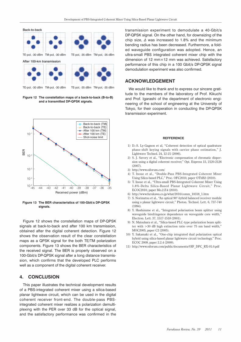
Figure 12 The constellation maps of a back-to-back (B-to-B) and a transmitted DP-QPSK signals.
Received power (dBm)
BE
R
10-1
10-2
10-3
10-4
10-5
-45 -44 -43 -42 -41 -40 -39 -38 -37 -36 -35
Figure 13 The BER characteristics of 100-Gbit/s DP-QPSK signals.
Back-to-back (TM)Back-to-back (TE)After 100 km (TM)After 100 km (TE)Shot-noise limit
Figure 12 shows the constellation maps of DP-QPSKsignals at back-to-back and after 100 km transmission,obtained after the digital coherent detection. Figure 12shows the observation result of the clear constellationmaps as a QPSK signal for the both TE/TM polarizationcomponents.Figure13showstheBERcharacteristicsofthe received signal. The BER is properly observed on a100-Gbit/sDP-QPSKsignalafteralongdistancetransmis-sion, which confirms that the developed PLC performswellasacomponentofthedigitalcoherentreceiver.
4. CONCLUSION
Thispaperillustratesthetechnicaldevelopmentresultsof a PBS-integrated coherent mixer using a silica-basedplanar lightwavecircuit,whichcanbeused in thedigitalcoherent receiver front-end. The double-pass PBS-integratedcoherentmixerrealizesapolarizationdemulti-plexing with the PER over 33 dB for the optical signal,and the satisfactory performance was confirmed in the
transmission experiment to demodulate a 40-Gbit/sDP-QPSKsignal.Ontheotherhand,fordownsizingofthechip size,Δ was increased to 1.8% and the minimumbendingradiushasbeendecreased.Furthermore,afold-ed waveguide configuration was adopted. Hence, anultra-small PBS integrated coherent mixer chip with thedimensionof12mm×12mmwasachieved.Satisfactoryperformanceof thischip ina100Gbit/sDP-QPSKsignaldemodulationexperimentwasalsoconfirmed.
ACKNOWLEDGEMENT
Wewouldliketothankandtoexpressoursinceregrati-tude to the members of the laboratory of Prof. Kikuchiand Prof. Igarashi of the department of electronic engi-neeringof the schoolof engineeringat theUniversityofTokyo, for their cooperation in conducting the DP-QPSKtransmissionexperiment.
REFFERENCE
1) D.-S. Ly-Gagnon et al, “Coherent detection of optical quadrature phase-shift keying signals with carrier phase estimation,” J. Lightwave Technol. 24, 12-21 (2006).
2) S. J. Savory et al., “Electronic compensation of chromatic disper-sion using a digital coherent receiver,” Opt. Express 15, 2120-2126 (2007).
3) http://www.oiforum.com/ 4) T. Inoue et al., “Double-Pass PBS-Integrated Coherent Mixer
Using Silica-based PLC,” Proc. OFC2010, paper OThB2 (2010). 5) T. Inoue et al., “Ultra-small PBS-Integrated Coherent Mixer Using
1.8%-Delta Silica-Based Planar Lightwave Circuit,” Proc. ECOC2010, paper Mo.2.F.4 (2010).
6) http://www.furukawa.co.jp/what/2010/comm_10318_1.htm 7) S. Norimatsu et al., “An optical 90°-hybrid balanced receiver module
using a planar lightwave circuit,” Photon. Technol. Lett. 6, 737-740 (1994).
8) Y. Hashizume et al., “Integrated polarisation beam splitter using waveguide birefringence dependence on waveguide core width,” Electron. Lett. 37, 1517-1518 (2001).
9) N. Matsubara et al., “Silica-based PLC-type polarization beam split-ter with >30 dB high extinction ratio over 75 nm band width,” MOC2005, paper C2 (2005).
10) Y. Sakamaki et al., “One-chip integrated dual polarization optical hybrid using silica-based planar lightwave circuit technology,” Proc. ECOC 2009, paper 2.2.4 (2009).
11) http://www.oiforum.com/public/documents/OIF_DPC_RX-01.0.pdf
![PharmacologicalCharacterizationofaBetaine/GABATransporter1 ...1552 Neurochemical Research (2020) 45:1551–1565 1 3 transportersnamedGAT1,GAT2,GAT3andBGT1[13], accordingtotheIUPHARnomenclature[14].GATsbelong](https://img.pdfslide.net/doc/110x75/60e18163d2526c2182155678/pharmacologicalcharacterizationofabetainegabatransporter1-1552-neurochemical.jpg)
![Tunable Erbium-Doped Fiber Lasers Using Various Inline Fiber … · 2016-02-18 · erbium-doped fiber lasers [4], distributed feedback fiber lasers [5], and Brillouin erbium-doped](https://img.pdfslide.net/doc/110x75/5f5d6d92d306cb22521e3c0b/tunable-erbium-doped-fiber-lasers-using-various-inline-fiber-2016-02-18-erbium-doped.jpg)


![弗莱彻建筑史 - supertypesetting.com · 集会大厅,普里恩(Ecclesiasterion/ assembly hall, Priene)[167][168] 集体农场(Kibbutzim/ collective settlements) [1551][1552]](https://img.pdfslide.net/doc/110x75/5e9cde98bc8798793063803c/ec-eioeeoeecclesiasterion-assembly-hall-priene167168.jpg)