Embed Size (px)
Citation preview
© Copyright 2015 DS&A LLC
David L. Saums, Principal DS&A LLC
Amesbury MA USA www.dsa-thermal.com
Keynote Presentation
IMAPS France 10th Anniversary Workshop on Thermal Management and Micropackaging
La Rochelle, France 4-5 February 2015
Developments in Advanced Thermal Materials
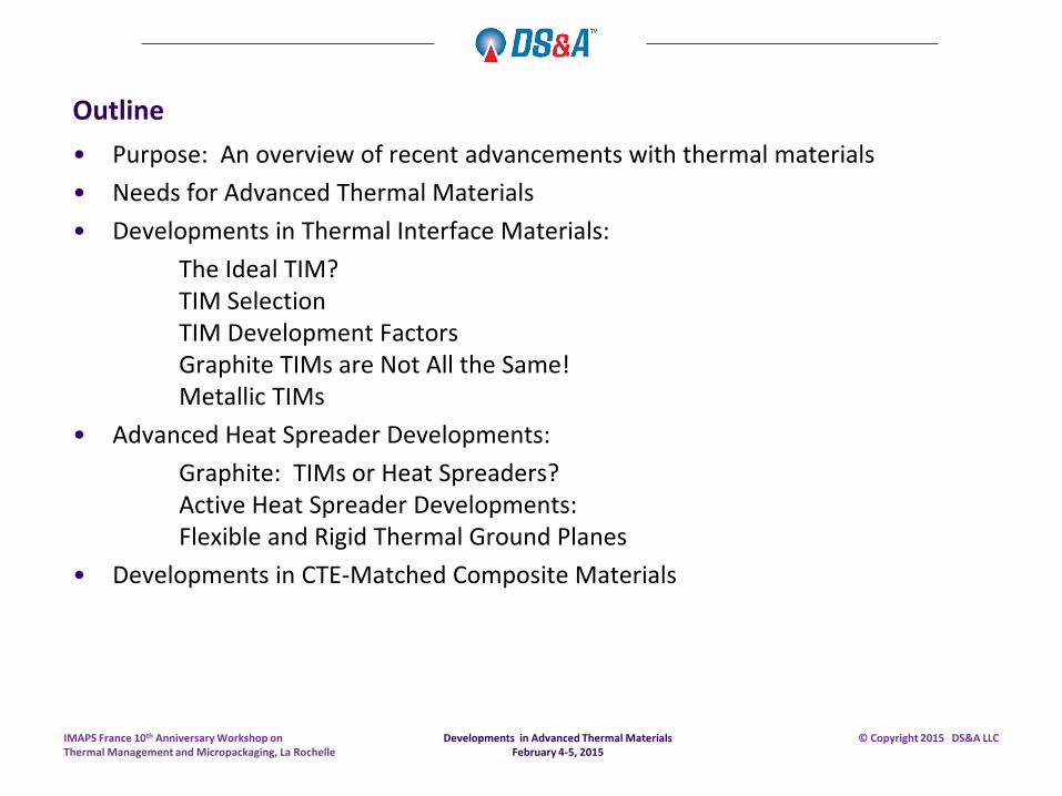
Outline
• Purpose: An overview of recent advancements with thermal materials
• Needs for Advanced Thermal Materials
• Developments in Thermal Interface Materials:
The Ideal TIM? TIM Selection TIM Development Factors Graphite TIMs are Not All the Same! Metallic TIMs
• Advanced Heat Spreader Developments:
Graphite: TIMs or Heat Spreaders? Active Heat Spreader Developments: Flexible and Rigid Thermal Ground Planes
• Developments in CTE-Matched Composite Materials
Developments in Advanced Thermal Materials February 4-5, 2015
IMAPS France 10th Anniversary Workshop on Thermal Management and Micropackaging, La Rochelle
© Copyright 2015 DS&A LLC
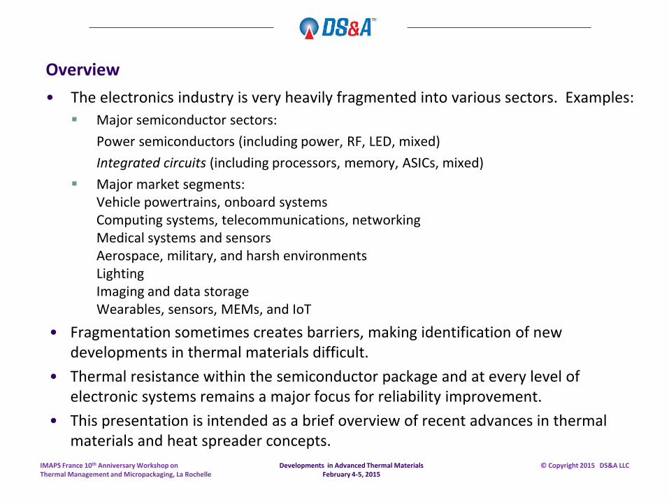
Overview
• The electronics industry is very heavily fragmented into various sectors. Examples:
Major semiconductor sectors:
Power semiconductors (including power, RF, LED, mixed)
Integrated circuits (including processors, memory, ASICs, mixed)
Major market segments: Vehicle powertrains, onboard systems Computing systems, telecommunications, networking Medical systems and sensors Aerospace, military, and harsh environments Lighting Imaging and data storage Wearables, sensors, MEMs, and IoT
• Fragmentation sometimes creates barriers, making identification of new developments in thermal materials difficult.
• Thermal resistance within the semiconductor package and at every level of electronic systems remains a major focus for reliability improvement.
• This presentation is intended as a brief overview of recent advances in thermal materials and heat spreader concepts.
Developments in Advanced Thermal Materials February 4-5, 2015
IMAPS France 10th Anniversary Workshop on Thermal Management and Micropackaging, La Rochelle
© Copyright 2015 DS&A LLC
Developments in Thermal Interface Materials
Developments in Advanced Thermal Materials February 4-5, 2015
IMAPS France 10th Anniversary Workshop on Thermal Management and Micropackaging, La Rochelle
© Copyright 2015 DS&A LLC
Is an “Ideal TIM” Possible to Develop?
• Is an “ideal” TIM material specification possible to develop?
• Can one TIM be a universal solution?
• Caveats:
Required functions of different types of TIM materials determine product specifications for an “ideal” TIM by material type.
A major distinction must be made between TIM material types which require mechanical fastening and those that do not – such as adhesives.
Developments in Advanced Thermal Materials February 4-5, 2015
IMAPS France 10th Anniversary Workshop on Thermal Management and Micropackaging, La Rochelle
© Copyright 2015 DS&A LLC
Is an “Ideal TIM” Possible to Develop?
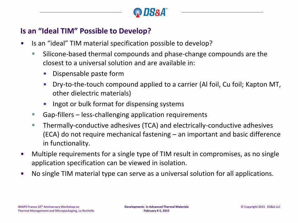
• Is an “ideal” TIM material specification possible to develop?
Silicone-based thermal compounds and phase-change compounds are the closest to a universal solution and are available in:
• Dispensable paste form
• Dry-to-the-touch compound applied to a carrier (Al foil, Cu foil; Kapton MT, other dielectric materials)
• Ingot or bulk format for dispensing systems
Gap-fillers – less-challenging application requirements
Thermally-conductive adhesives (TCA) and electrically-conductive adhesives (ECA) do not require mechanical fastening – an important and basic difference in functionality.
• Multiple requirements for a single type of TIM result in compromises, as no single application specification can be viewed in isolation.
• No single TIM material type can serve as a universal solution for all applications.
Developments in Advanced Thermal Materials February 4-5, 2015
IMAPS France 10th Anniversary Workshop on Thermal Management and Micropackaging, La Rochelle
© Copyright 2015 DS&A LLC
How is a TIM Selected?
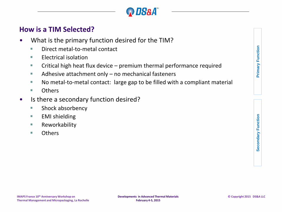
• What is the primary function desired for the TIM? Direct metal-to-metal contact
Electrical isolation
Critical high heat flux device – premium thermal performance required
Adhesive attachment only – no mechanical fasteners
No metal-to-metal contact: large gap to be filled with a compliant material
Others
• Is there a secondary function desired? Shock absorbency
EMI shielding
Reworkability
Others
Developments in Advanced Thermal Materials February 4-5, 2015
IMAPS France 10th Anniversary Workshop on Thermal Management and Micropackaging, La Rochelle
© Copyright 2015 DS&A LLC
Pri
mary
Fu
ncti
on
S
eco
nd
ary
Fu
ncti
on
TIM Material Function – How are TIM Materials Used in Practice?
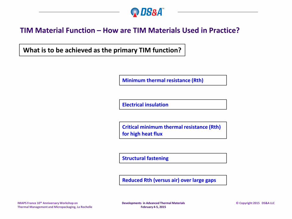
Minimum thermal resistance (Rth)
Structural fastening
Reduced Rth (versus air) over large gaps
Electrical insulation
Critical minimum thermal resistance (Rth) for high heat flux
What is to be achieved as the primary TIM function?
Developments in Advanced Thermal Materials February 4-5, 2015
IMAPS France 10th Anniversary Workshop on Thermal Management and Micropackaging, La Rochelle
© Copyright 2015 DS&A LLC
TIM Material Function – How are TIM Materials Used in Practice?
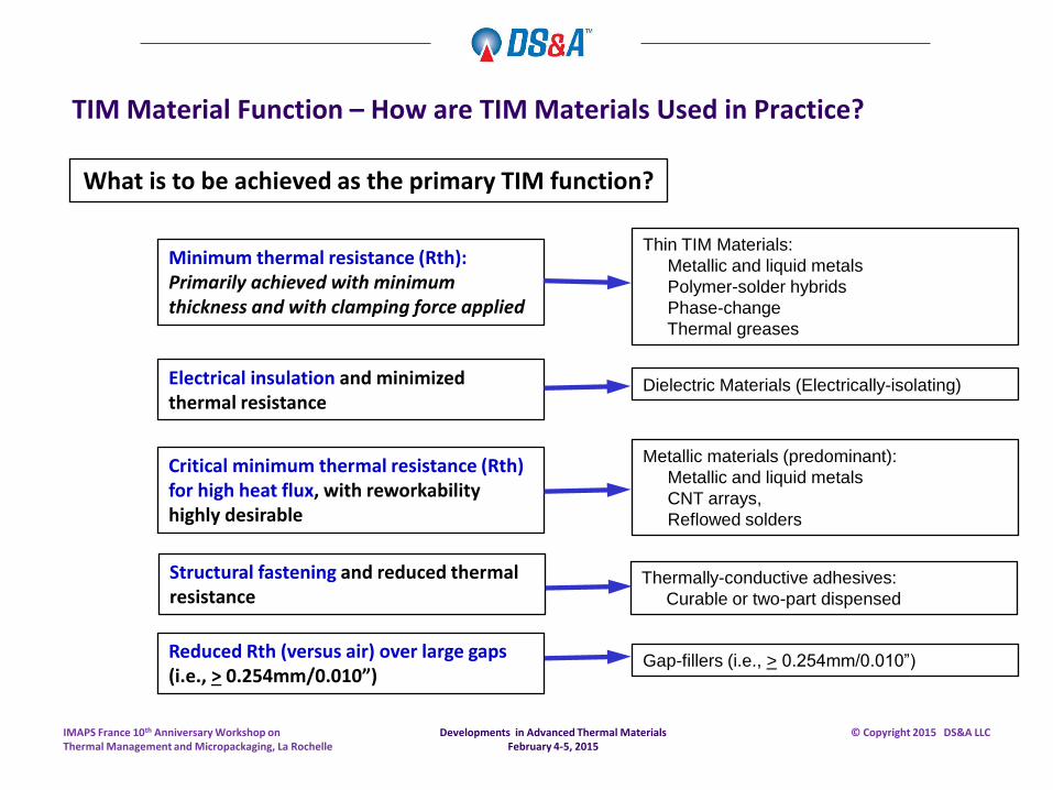
What is to be achieved as the primary TIM function?
Minimum thermal resistance (Rth): Primarily achieved with minimum thickness and with clamping force applied
Thin TIM Materials:
Metallic and liquid metals
Polymer-solder hybrids
Phase-change
Thermal greases
Thermally-conductive adhesives:
Curable or two-part dispensed
Structural fastening and reduced thermal resistance
Reduced Rth (versus air) over large gaps (i.e., > 0.254mm/0.010”)
Gap-fillers (i.e., > 0.254mm/0.010”)
Electrical insulation and minimized thermal resistance
Dielectric Materials (Electrically-isolating)
Critical minimum thermal resistance (Rth) for high heat flux, with reworkability highly desirable
Metallic materials (predominant):
Metallic and liquid metals
CNT arrays,
Reflowed solders
Developments in Advanced Thermal Materials February 4-5, 2015
IMAPS France 10th Anniversary Workshop on Thermal Management and Micropackaging, La Rochelle
© Copyright 2015 DS&A LLC
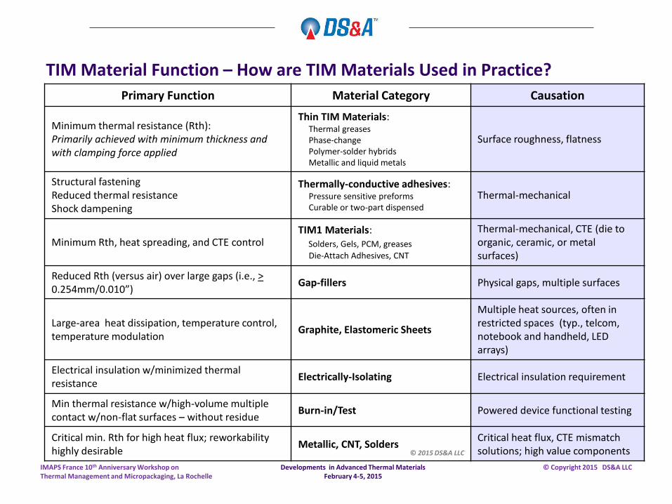
TIM Material Function – How are TIM Materials Used in Practice?
Primary Function Material Category Causation
Minimum thermal resistance (Rth): Primarily achieved with minimum thickness and with clamping force applied
Thin TIM Materials: Thermal greases Phase-change Polymer-solder hybrids Metallic and liquid metals
Surface roughness, flatness
Structural fastening Reduced thermal resistance Shock dampening
Thermally-conductive adhesives: Pressure sensitive preforms Curable or two-part dispensed
Thermal-mechanical
Minimum Rth, heat spreading, and CTE control TIM1 Materials: Solders, Gels, PCM, greases
Die-Attach Adhesives, CNT
Thermal-mechanical, CTE (die to organic, ceramic, or metal surfaces)
Reduced Rth (versus air) over large gaps (i.e., > 0.254mm/0.010”)
Gap-fillers Physical gaps, multiple surfaces
Large-area heat dissipation, temperature control, temperature modulation
Graphite, Elastomeric Sheets
Multiple heat sources, often in restricted spaces (typ., telcom, notebook and handheld, LED arrays)
Electrical insulation w/minimized thermal resistance
Electrically-Isolating Electrical insulation requirement
Min thermal resistance w/high-volume multiple contact w/non-flat surfaces – without residue
Burn-in/Test Powered device functional testing
Critical min. Rth for high heat flux; reworkability highly desirable
Metallic, CNT, Solders Critical heat flux, CTE mismatch solutions; high value components © 2015 DS&A LLC
Developments in Advanced Thermal Materials February 4-5, 2015
IMAPS France 10th Anniversary Workshop on Thermal Management and Micropackaging, La Rochelle
© Copyright 2015 DS&A LLC
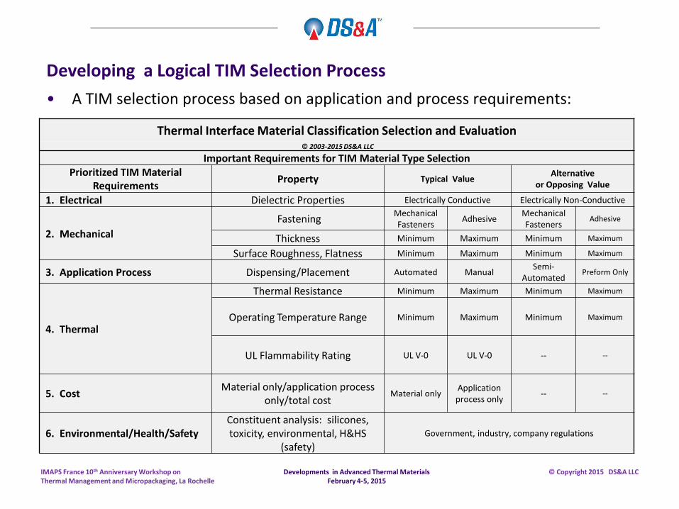
Developing a Logical TIM Selection Process
• A TIM selection process based on application and process requirements:
Thermal Interface Material Classification Selection and Evaluation
© 2003-2015 DS&A LLC
Important Requirements for TIM Material Type Selection Prioritized TIM Material
Requirements Property Typical Value
Alternative or Opposing Value
1. Electrical Dielectric Properties Electrically Conductive Electrically Non-Conductive
2. Mechanical
Fastening Mechanical Fasteners
Adhesive Mechanical Fasteners
Adhesive
Thickness Minimum Maximum Minimum Maximum
Surface Roughness, Flatness Minimum Maximum Minimum Maximum
3. Application Process Dispensing/Placement Automated Manual Semi-
Automated Preform Only
4. Thermal
Thermal Resistance Minimum Maximum Minimum Maximum
Operating Temperature Range Minimum Maximum Minimum Maximum
UL Flammability Rating UL V-0 UL V-0 -- --
5. Cost Material only/application process
only/total cost Material only
Application process only
-- --
6. Environmental/Health/Safety Constituent analysis: silicones, toxicity, environmental, H&HS
(safety)
Government, industry, company regulations
Developments in Advanced Thermal Materials February 4-5, 2015
IMAPS France 10th Anniversary Workshop on Thermal Management and Micropackaging, La Rochelle
© Copyright 2015 DS&A LLC
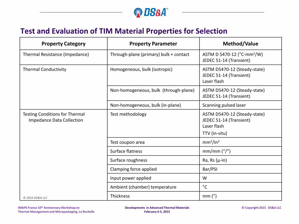
Test and Evaluation of TIM Material Properties for Selection
Property Category Property Parameter Method/Value
Thermal Resistance (Impedance) Through-plane (primary) bulk + contact ASTM D 5470-12 (°C-mm2/W) JEDEC 51-14 (Transient)
Thermal Conductivity Homogeneous, bulk (isotropic) ASTM D5470-12 (Steady-state) JEDEC 51-14 (Transient) Laser flash
Non-homogeneous, bulk (through-plane) ASTM D5470-12 (Steady-state) JEDEC 51-14 (Transient)
Non-homogeneous, bulk (in-plane) Scanning pulsed laser
Testing Conditions for Thermal Impedance Data Collection
Test methodology
ASTM D5470-12 (Steady-state) JEDEC 51-14 (Transient) Laser flash
TTV (in-situ)
Test coupon area mm2/in2
Surface flatness mm/mm (“/”)
Surface roughness Ra, Rs (µ-in)
Clamping force applied Bar/PSI
Input power applied W
Ambient (chamber) temperature °C
Thickness mm (”) © 2015 DS&A LLC
Developments in Advanced Thermal Materials February 4-5, 2015
IMAPS France 10th Anniversary Workshop on Thermal Management and Micropackaging, La Rochelle
© Copyright 2015 DS&A LLC
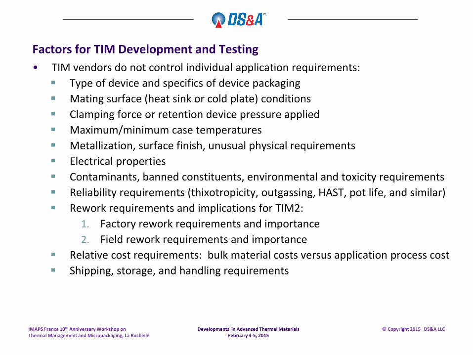
Factors for TIM Development and Testing
• TIM vendors do not control individual application requirements:
Type of device and specifics of device packaging
Mating surface (heat sink or cold plate) conditions
Clamping force or retention device pressure applied
Maximum/minimum case temperatures
Metallization, surface finish, unusual physical requirements
Electrical properties
Contaminants, banned constituents, environmental and toxicity requirements
Reliability requirements (thixotropicity, outgassing, HAST, pot life, and similar)
Rework requirements and implications for TIM2:
1. Factory rework requirements and importance
2. Field rework requirements and importance
Relative cost requirements: bulk material costs versus application process cost
Shipping, storage, and handling requirements
Developments in Advanced Thermal Materials February 4-5, 2015
IMAPS France 10th Anniversary Workshop on Thermal Management and Micropackaging, La Rochelle
© Copyright 2015 DS&A LLC
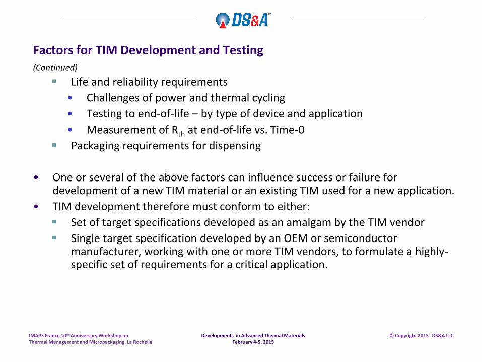
Factors for TIM Development and Testing (Continued)
Life and reliability requirements
• Challenges of power and thermal cycling
• Testing to end-of-life – by type of device and application
• Measurement of Rth at end-of-life vs. Time-0
Packaging requirements for dispensing
• One or several of the above factors can influence success or failure for development of a new TIM material or an existing TIM used for a new application.
• TIM development therefore must conform to either:
Set of target specifications developed as an amalgam by the TIM vendor
Single target specification developed by an OEM or semiconductor manufacturer, working with one or more TIM vendors, to formulate a highly-specific set of requirements for a critical application.
Developments in Advanced Thermal Materials February 4-5, 2015
IMAPS France 10th Anniversary Workshop on Thermal Management and Micropackaging, La Rochelle
© Copyright 2015 DS&A LLC
Attributes Which Apply to all TIM Materials
Developments in Advanced Thermal Materials February 4-5, 2015
IMAPS France 10th Anniversary Workshop on Thermal Management and Micropackaging, La Rochelle
© Copyright 2015 DS&A LLC
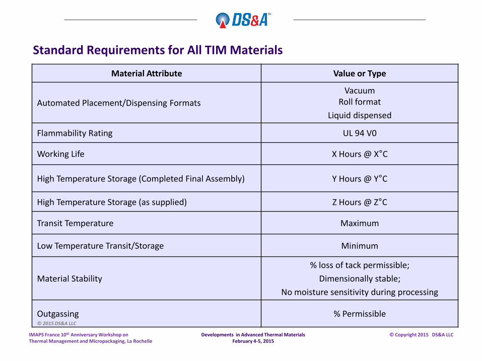
Standard Requirements for All TIM Materials
Material Attribute Value or Type
Automated Placement/Dispensing Formats
Vacuum Roll format
Liquid dispensed
Flammability Rating UL 94 V0
Working Life X Hours @ X°C
High Temperature Storage (Completed Final Assembly) Y Hours @ Y°C
High Temperature Storage (as supplied) Z Hours @ Z°C
Transit Temperature Maximum
Low Temperature Transit/Storage Minimum
Material Stability
% loss of tack permissible;
Dimensionally stable;
No moisture sensitivity during processing
Outgassing % Permissible © 2015 DS&A LLC
Developments in Advanced Thermal Materials February 4-5, 2015
IMAPS France 10th Anniversary Workshop on Thermal Management and Micropackaging, La Rochelle
© Copyright 2015 DS&A LLC
Example, Development Target Specifications, Ideal Attributes for a Single Category of TIM Material
Developments in Advanced Thermal Materials February 4-5, 2015
IMAPS France 10th Anniversary Workshop on Thermal Management and Micropackaging, La Rochelle
© Copyright 2015 DS&A LLC
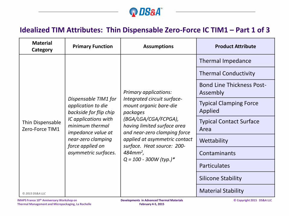
Idealized TIM Attributes: Thin Dispensable Zero-Force IC TIM1 – Part 1 of 3
Material Category
Primary Function Assumptions Product Attribute
Thin Dispensable Zero-Force TIM1
Dispensable TIM1 for application to die backside for flip chip IC applications with minimum thermal impedance value at near-zero clamping force applied on asymmetric surfaces.
Primary applications: Integrated circuit surface-mount organic bare-die packages (BGA/LGA/CGA/FCPGA), having limited surface area and near-zero clamping force applied at asymmetric contact surface. Heat source: 200-484mm2, Q = 100 - 300W (typ.)*
Thermal Impedance
Thermal Conductivity
Bond Line Thickness Post-Assembly
Typical Clamping Force Applied
Typical Contact Surface Area
Wettability
Contaminants
Particulates
Silicone Stability
Material Stability © 2015 DS&A LLC
Developments in Advanced Thermal Materials February 4-5, 2015
IMAPS France 10th Anniversary Workshop on Thermal Management and Micropackaging, La Rochelle
© Copyright 2015 DS&A LLC
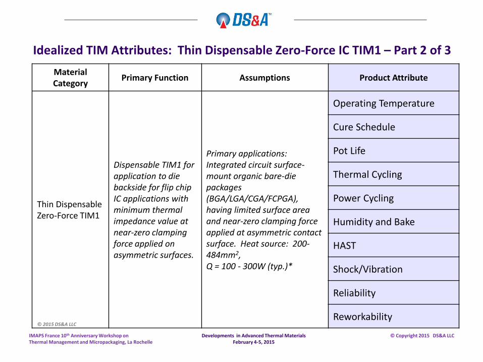
Idealized TIM Attributes: Thin Dispensable Zero-Force IC TIM1 – Part 2 of 3
Material Category
Primary Function Assumptions Product Attribute
Thin Dispensable Zero-Force TIM1
Dispensable TIM1 for application to die backside for flip chip IC applications with minimum thermal impedance value at near-zero clamping force applied on asymmetric surfaces.
Primary applications: Integrated circuit surface-mount organic bare-die packages (BGA/LGA/CGA/FCPGA), having limited surface area and near-zero clamping force applied at asymmetric contact surface. Heat source: 200-484mm2, Q = 100 - 300W (typ.)*
Operating Temperature
Cure Schedule
Pot Life
Thermal Cycling
Power Cycling
Humidity and Bake
HAST
Shock/Vibration
Reliability
Reworkability © 2015 DS&A LLC
Developments in Advanced Thermal Materials February 4-5, 2015
IMAPS France 10th Anniversary Workshop on Thermal Management and Micropackaging, La Rochelle
© Copyright 2015 DS&A LLC
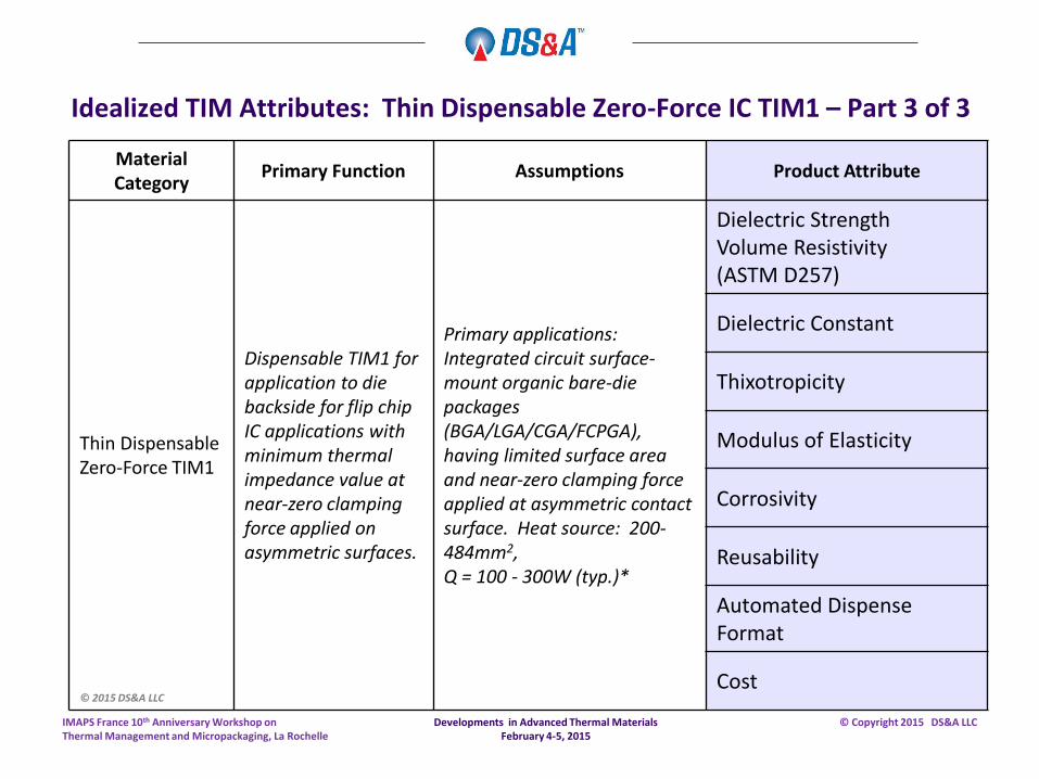
Idealized TIM Attributes: Thin Dispensable Zero-Force IC TIM1 – Part 3 of 3
Material Category
Primary Function Assumptions Product Attribute
Thin Dispensable Zero-Force TIM1
Dispensable TIM1 for application to die backside for flip chip IC applications with minimum thermal impedance value at near-zero clamping force applied on asymmetric surfaces.
Primary applications: Integrated circuit surface-mount organic bare-die packages (BGA/LGA/CGA/FCPGA), having limited surface area and near-zero clamping force applied at asymmetric contact surface. Heat source: 200-484mm2, Q = 100 - 300W (typ.)*
Dielectric Strength Volume Resistivity (ASTM D257)
Dielectric Constant
Thixotropicity
Modulus of Elasticity
Corrosivity
Reusability
Automated Dispense Format
Cost © 2015 DS&A LLC
Developments in Advanced Thermal Materials February 4-5, 2015
IMAPS France 10th Anniversary Workshop on Thermal Management and Micropackaging, La Rochelle
© Copyright 2015 DS&A LLC
Oriented Fiber Graphite TIM
Developments in Advanced Thermal Materials February 4-5, 2015
IMAPS France 10th Anniversary Workshop on Thermal Management and Micropackaging, La Rochelle
© Copyright 2015 DS&A LLC
Developments in Oriented Fiber Graphite TIM
• Not all oriented-graphite TIM materials perform the same.
Testing is required to determine thermal performance of any oriented-graphite TIM.
Wide variation from manufacturer to manufacturer.
Many different grades.
Many “Graphite TIM materials” are actually heat spreaders and not TIM materials at all.
Developments in Advanced Thermal Materials February 4-5, 2015
IMAPS France 10th Anniversary Workshop on Thermal Management and Micropackaging, La Rochelle
© Copyright 2015 DS&A LLC
Developments in Oriented Fiber Graphite TIM
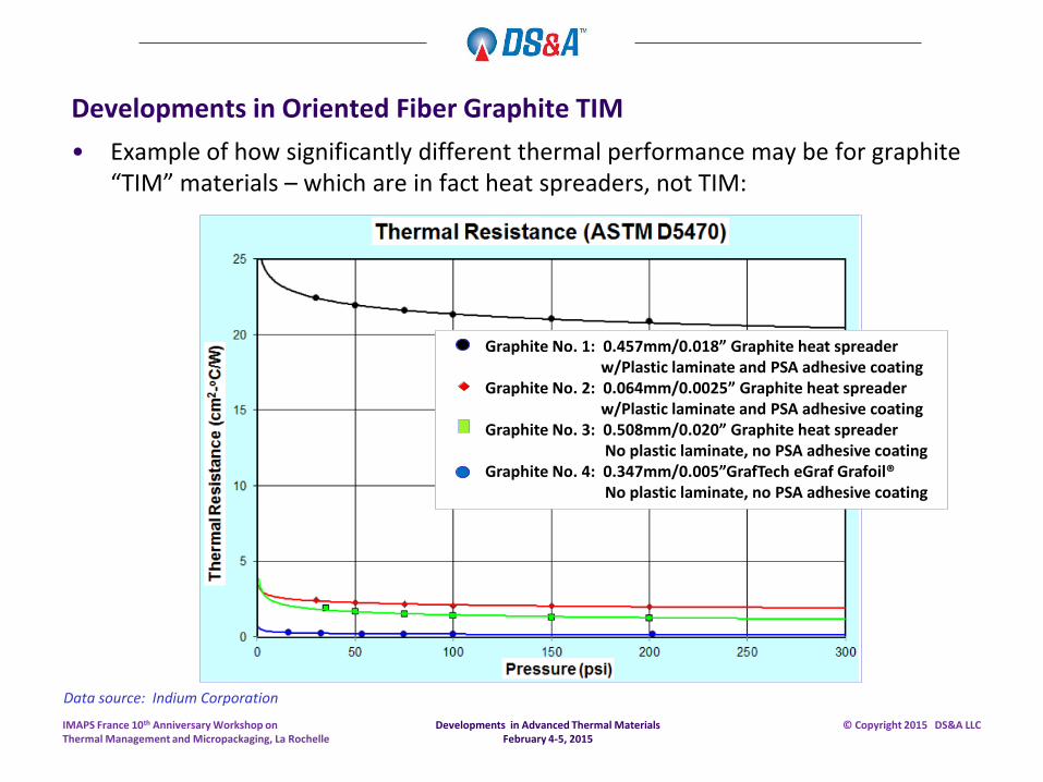
• Example of how significantly different thermal performance may be for graphite “TIM” materials – which are in fact heat spreaders, not TIM:
Developments in Advanced Thermal Materials February 4-5, 2015
IMAPS France 10th Anniversary Workshop on Thermal Management and Micropackaging, La Rochelle
© Copyright 2015 DS&A LLC
Data source: Indium Corporation
Graphite No. 1: 0.457mm/0.018” Graphite heat spreader w/Plastic laminate and PSA adhesive coating Graphite No. 2: 0.064mm/0.0025” Graphite heat spreader w/Plastic laminate and PSA adhesive coating Graphite No. 3: 0.508mm/0.020” Graphite heat spreader No plastic laminate, no PSA adhesive coating Graphite No. 4: 0.347mm/0.005”GrafTech eGraf Grafoil® No plastic laminate, no PSA adhesive coating
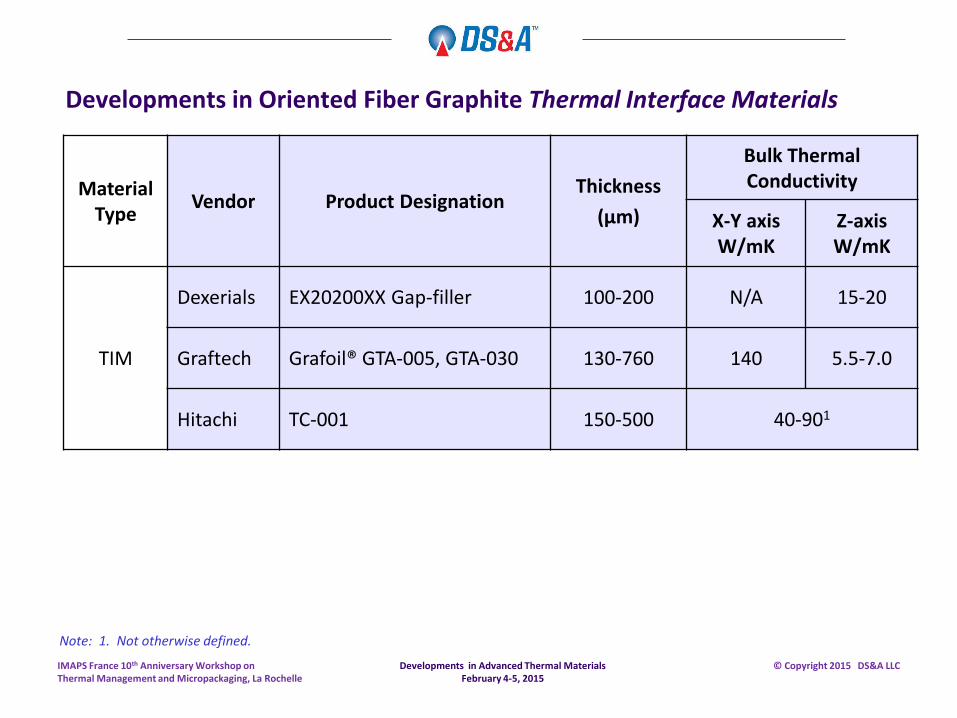
Developments in Oriented Fiber Graphite Thermal Interface Materials
Material Type
Vendor Product Designation Thickness
(µm)
Bulk Thermal Conductivity
X-Y axis W/mK
Z-axis W/mK
TIM
Dexerials EX20200XX Gap-filler 100-200 N/A 15-20
Graftech Grafoil® GTA-005, GTA-030 130-760 140 5.5-7.0
Hitachi TC-001 150-500 40-901
Developments in Advanced Thermal Materials February 4-5, 2015
IMAPS France 10th Anniversary Workshop on Thermal Management and Micropackaging, La Rochelle
© Copyright 2015 DS&A LLC
Note: 1. Not otherwise defined.
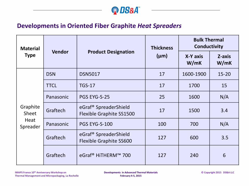
Developments in Oriented Fiber Graphite Heat Spreaders
Material Type
Vendor Product Designation Thickness
(µm)
Bulk Thermal Conductivity
X-Y axis W/mK
Z-axis W/mK
Graphite Sheet Heat
Spreader
DSN DSN5017 17 1600-1900 15-20
TTCL TGS-17 17 1700 15
Panasonic PGS EYG-S-25 25 1600 N/A
Graftech eGraf® SpreaderShield Flexible Graphite SS1500
17 1500 3.4
Panasonic PGS EYG-S-100 100 700 N/A
Graftech eGraf® SpreaderShield Flexible Graphite SS600
127 600 3.5
Graftech eGraf® HiTHERM™ 700 127 240 6
Developments in Advanced Thermal Materials February 4-5, 2015
IMAPS France 10th Anniversary Workshop on Thermal Management and Micropackaging, La Rochelle
© Copyright 2015 DS&A LLC
Developments in Metallic TIM
Developments in Advanced Thermal Materials February 4-5, 2015
IMAPS France 10th Anniversary Workshop on Thermal Management and Micropackaging, La Rochelle
© Copyright 2015 DS&A LLC
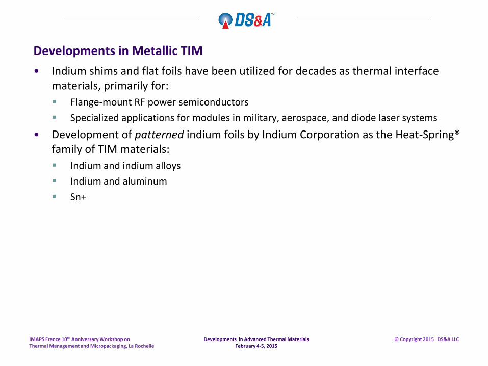
Developments in Metallic TIM
• Indium shims and flat foils have been utilized for decades as thermal interface materials, primarily for:
Flange-mount RF power semiconductors
Specialized applications for modules in military, aerospace, and diode laser systems
• Development of patterned indium foils by Indium Corporation as the Heat-Spring® family of TIM materials:
Indium and indium alloys
Indium and aluminum
Sn+
Developments in Advanced Thermal Materials February 4-5, 2015
IMAPS France 10th Anniversary Workshop on Thermal Management and Micropackaging, La Rochelle
© Copyright 2015 DS&A LLC
Developments in Metallic TIM
Developments in Advanced Thermal Materials February 4-5, 2015
IMAPS France 10th Anniversary Workshop on Thermal Management and Micropackaging, La Rochelle
© Copyright 2015 DS&A LLC
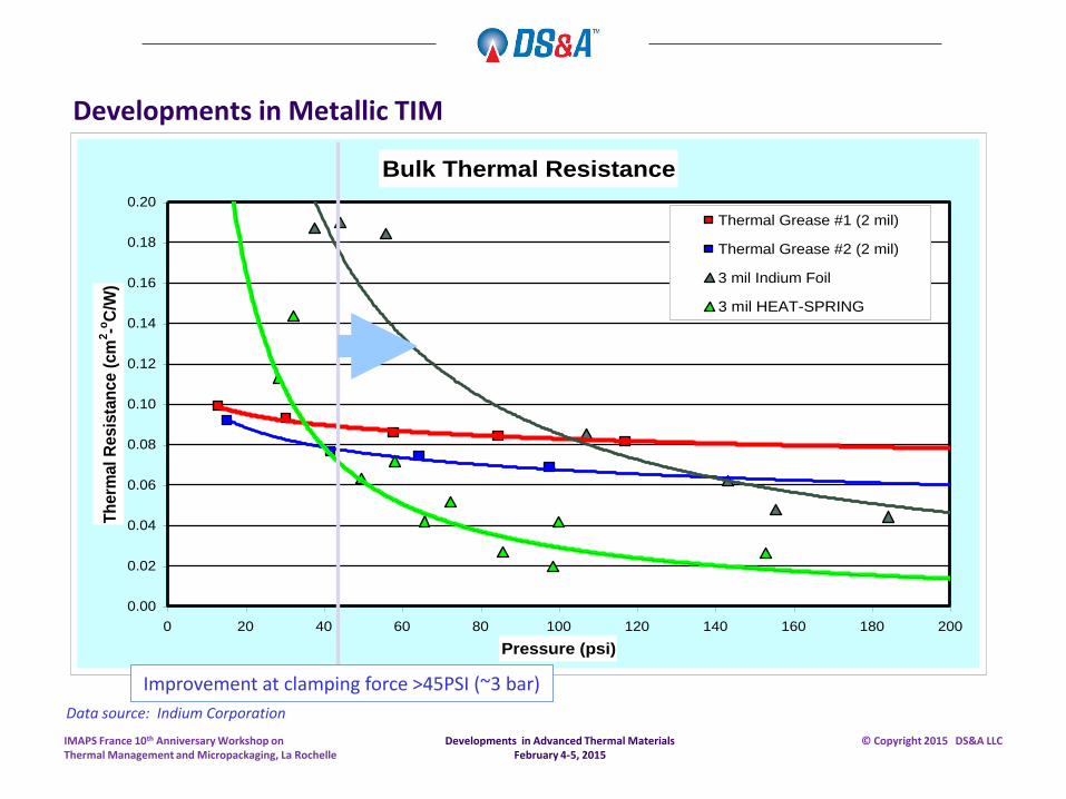
Bulk Thermal Resistance
0.00
0.02
0.04
0.06
0.08
0.10
0.12
0.14
0.16
0.18
0.20
0 20 40 60 80 100 120 140 160 180 200
Pressure (psi)
Th
erm
al R
esis
tan
ce (
cm
2-o
C/W
)
Thermal Grease #1 (2 mil)
Thermal Grease #2 (2 mil)
3 mil Indium Foil
3 mil HEAT-SPRING
Improvement at clamping force >45PSI (~3 bar)
Data source: Indium Corporation
Developments in Metallic TIM
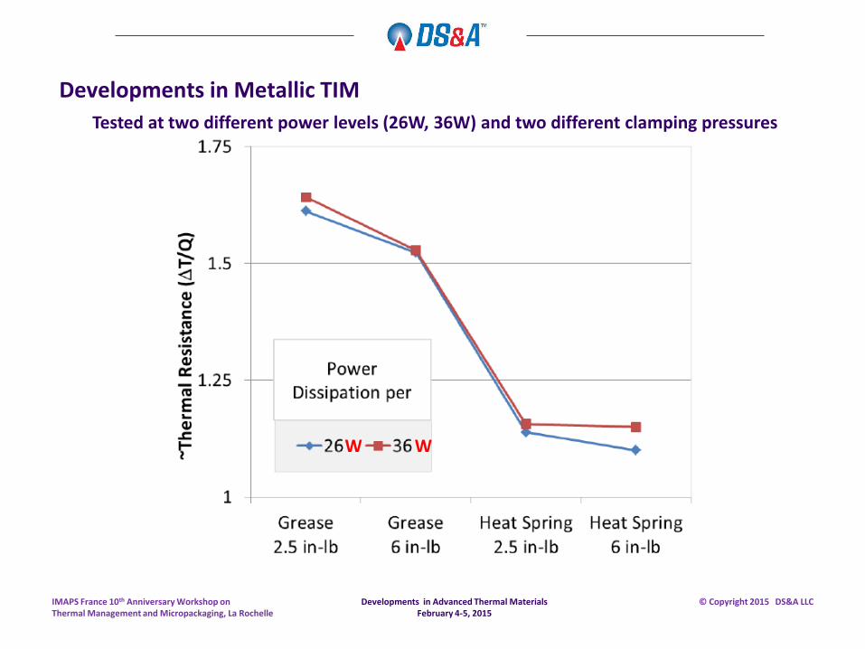
• An example of aerospace OEM testing to determine the improvement in thermal resistance for a flange-mount RF semiconductor package follows:
Two GaN RF devices (26W, 36W dissipation) mounted in identical flange-mount packages
Two different clamping forces tested
Indium “Heat-Spring” TIM versus traditional silicone-based thermal grease
On average, “Heat-Spring” reduced thermal resistance by 28% relative to grease
Average impact of different torque values was reduced from >6% to <2% w/”Heat-Spring”
Developments in Advanced Thermal Materials February 4-5, 2015
IMAPS France 10th Anniversary Workshop on Thermal Management and Micropackaging, La Rochelle
© Copyright 2015 DS&A LLC
Developments in Metallic TIM
Developments in Advanced Thermal Materials February 4-5, 2015
IMAPS France 10th Anniversary Workshop on Thermal Management and Micropackaging, La Rochelle
© Copyright 2015 DS&A LLC
W W
Tested at two different power levels (26W, 36W) and two different clamping pressures
Developments in Heat Spreader Materials: Aluminum-Stainless Steel Clad Heat Spreaders
Developments in Advanced Thermal Materials February 4-5, 2015
IMAPS France 10th Anniversary Workshop on Thermal Management and Micropackaging, La Rochelle
© Copyright 2015 DS&A LLC
Developments in Advanced Thermal Materials February 4-5, 2015
IMAPS France 10th Anniversary Workshop on Thermal Management and Micropackaging, La Rochelle
© Copyright 2015 DS&A LLC
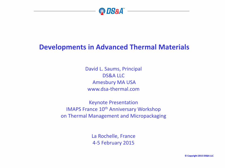
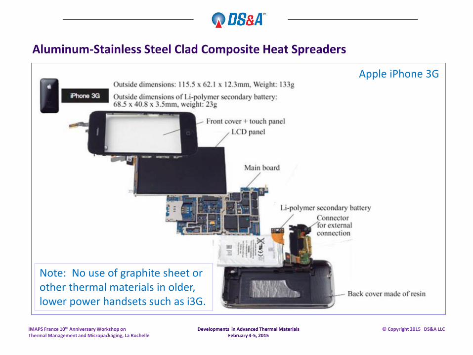
Aluminum-Stainless Steel Clad Composite Heat Spreaders
Apple iPhone 3G
Note: No use of graphite sheet or other thermal materials in older, lower power handsets such as i3G.
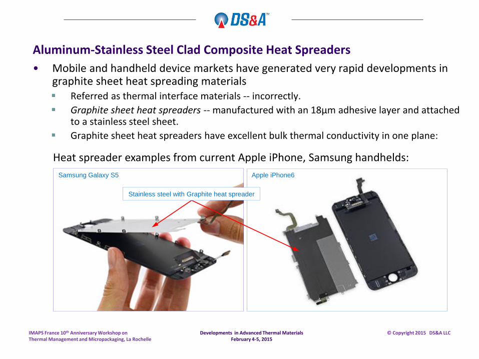
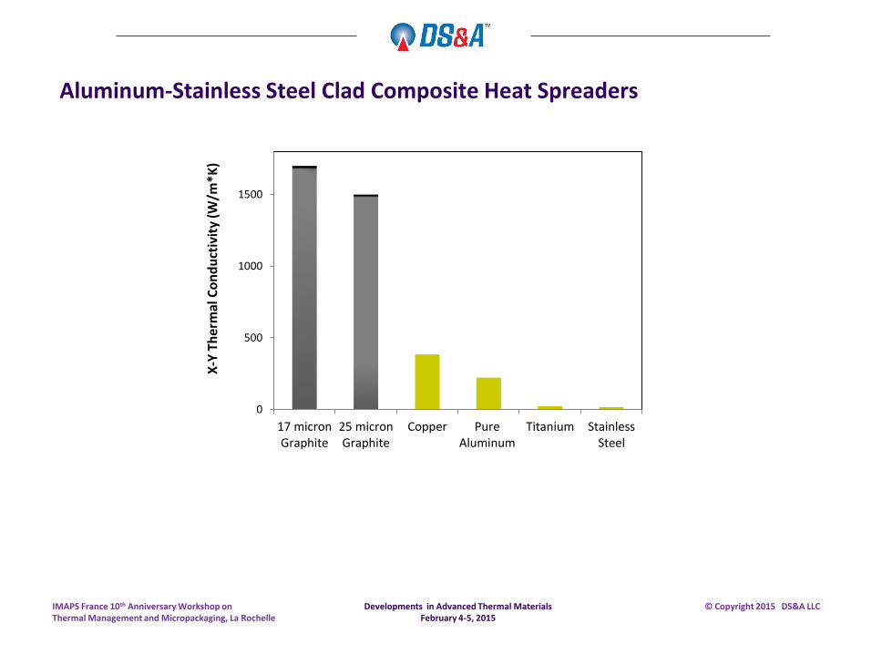
Aluminum-Stainless Steel Clad Composite Heat Spreaders
• Mobile and handheld device markets have generated very rapid developments in graphite sheet heat spreading materials Referred as thermal interface materials -- incorrectly.
Graphite sheet heat spreaders -- manufactured with an 18µm adhesive layer and attached to a stainless steel sheet.
Graphite sheet heat spreaders have excellent bulk thermal conductivity in one plane:
Heat spreader examples from current Apple iPhone, Samsung handhelds:
Samsung Galaxy S5 Apple iPhone6
Stainless steel with Graphite heat spreader
Developments in Advanced Thermal Materials February 4-5, 2015
IMAPS France 10th Anniversary Workshop on Thermal Management and Micropackaging, La Rochelle
© Copyright 2015 DS&A LLC
0
500
1000
1500
17 micronGraphite
25 micronGraphite
Copper PureAluminum
Titanium StainlessSteel
X-Y
Th
erm
al C
on
du
ctiv
ity
(W/m
*K)
Developments in Advanced Thermal Materials February 4-5, 2015
IMAPS France 10th Anniversary Workshop on Thermal Management and Micropackaging, La Rochelle
© Copyright 2015 DS&A LLC
Aluminum-Stainless Steel Clad Composite Heat Spreaders
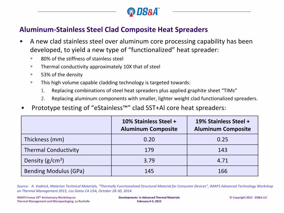
• A new clad stainless steel over aluminum core processing capability has been developed, to yield a new type of “functionalized” heat spreader: 80% of the stiffness of stainless steel
Thermal conductivity approximately 10X that of steel
53% of the density
This high volume capable cladding technology is targeted towards:
1. Replacing combinations of steel heat spreaders plus applied graphite sheet “TIMs”
2. Replacing aluminum components with smaller, lighter weight clad functionalized spreaders.
• Prototype testing of “eStainless™” clad SST+Al core heat spreaders:
Developments in Advanced Thermal Materials February 4-5, 2015
IMAPS France 10th Anniversary Workshop on Thermal Management and Micropackaging, La Rochelle
© Copyright 2015 DS&A LLC
Aluminum-Stainless Steel Clad Composite Heat Spreaders
10% Stainless Steel + Aluminum Composite
19% Stainless Steel + Aluminum Composite
Thickness (mm) 0.20 0.25
Thermal Conductivity 179 143
Density (g/cm3) 3.79 4.71
Bending Modulus (GPa) 145 166
Source: A. Vodnick, Materion Technical Materials, “Thermally Functionalized Structural Material for Consumer Devices”, IMAPS Advanced Technology Workshop on Thermal Management 2015, Los Gatos CA USA, October 28-30, 2014.
Developments in Active Heat Spreaders and Thermal Ground Planes
Developments in Advanced Thermal Materials February 4-5, 2015
IMAPS France 10th Anniversary Workshop on Thermal Management and Micropackaging, La Rochelle
© Copyright 2015 DS&A LLC
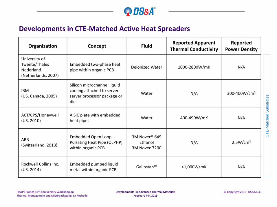
Developments in CTE-Matched Active Heat Spreaders
Organization Concept Fluid Reported Apparent
Thermal Conductivity Reported
Power Density
University of Twente/Thales Nederland (Netherlands, 2007)
Embedded two-phase heat pipe within organic PCB
Deionized Water 1000-2800W/mK N/A
IBM (US, Canada, 2005)
Silicon microchannel liquid cooling attached to server server processor package or die
Water N/A 300-400W/cm2
ACT/CPS/Honeywell (US, 2010)
AlSiC plate with embedded heat pipes
Water 400-490W/mK N/A
ABB (Switzerland, 2013)
Embedded Open Loop Pulsating Heat Pipe (OLPHP) within organic PCB
3M Novec® 649 Ethanol
3M Novec 7200 N/A 2.5W/cm2
Rockwell Collins Inc. (US, 2014)
Embedded pumped liquid metal within organic PCB
Galinstan™ >1,000W/mK N/A
CT
E-M
atc
hed S
ubstr
ate
s
Developments in Advanced Thermal Materials February 4-5, 2015
IMAPS France 10th Anniversary Workshop on Thermal Management and Micropackaging, La Rochelle
© Copyright 2015 DS&A LLC
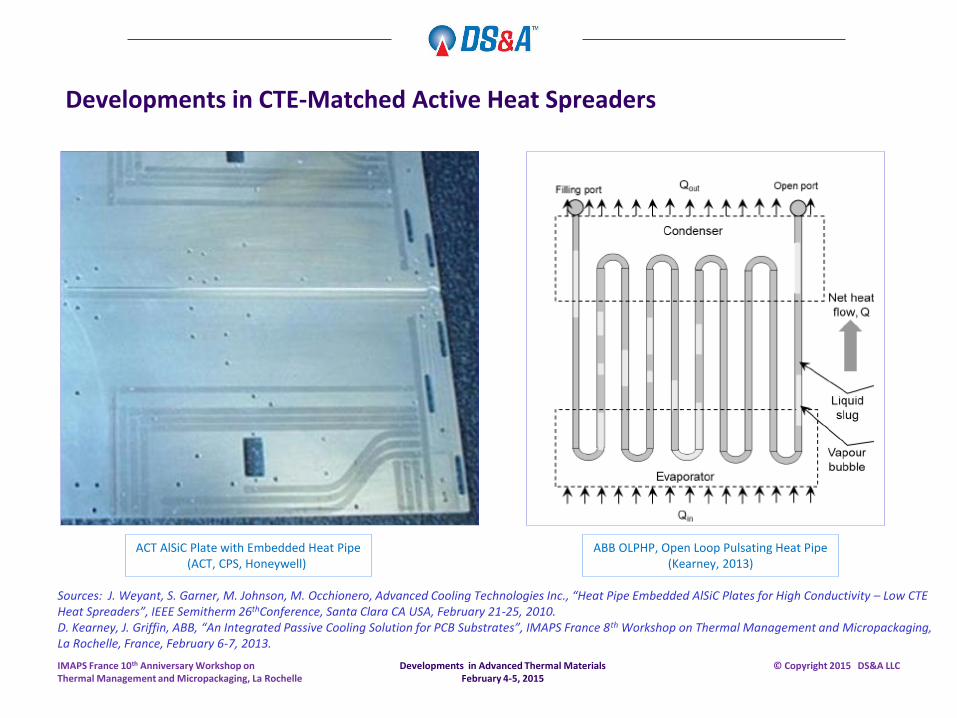
ABB OLPHP, Open Loop Pulsating Heat Pipe (Kearney, 2013)
ACT AlSiC Plate with Embedded Heat Pipe (ACT, CPS, Honeywell)
Developments in Advanced Thermal Materials February 4-5, 2015
IMAPS France 10th Anniversary Workshop on Thermal Management and Micropackaging, La Rochelle
© Copyright 2015 DS&A LLC
Developments in CTE-Matched Active Heat Spreaders
Sources: J. Weyant, S. Garner, M. Johnson, M. Occhionero, Advanced Cooling Technologies Inc., “Heat Pipe Embedded AlSiC Plates for High Conductivity – Low CTE Heat Spreaders”, IEEE Semitherm 26thConference, Santa Clara CA USA, February 21-25, 2010. D. Kearney, J. Griffin, ABB, “An Integrated Passive Cooling Solution for PCB Substrates”, IMAPS France 8th Workshop on Thermal Management and Micropackaging, La Rochelle, France, February 6-7, 2013.
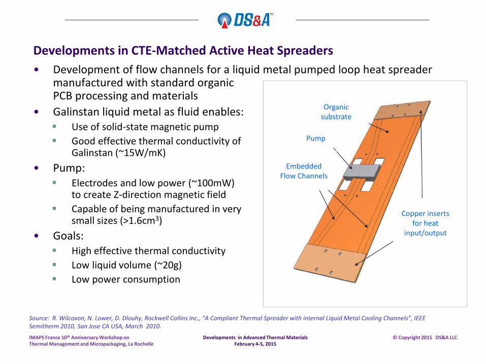
• Development of flow channels for a liquid metal pumped loop heat spreader manufactured with standard organic PCB processing and materials
• Galinstan liquid metal as fluid enables: Use of solid-state magnetic pump
Good effective thermal conductivity of Galinstan (~15W/mK)
• Pump: Electrodes and low power (~100mW)
to create Z-direction magnetic field
Capable of being manufactured in very small sizes (>1.6cm3)
• Goals: High effective thermal conductivity
Low liquid volume (~20g)
Low power consumption
Developments in CTE-Matched Active Heat Spreaders
Organic substrate
Pump
Embedded Flow Channels
Copper inserts for heat
input/output
Source: R. Wilcoxon, N. Lower, D. Dlouhy, Rockwell Collins Inc., “A Compliant Thermal Spreader with internal Liquid Metal Cooling Channels”, IEEE Semitherm 2010, San Jose CA USA, March 2010.
Developments in Advanced Thermal Materials February 4-5, 2015
IMAPS France 10th Anniversary Workshop on Thermal Management and Micropackaging, La Rochelle
© Copyright 2015 DS&A LLC
Developments in CTE-Matched Active Heat Spreaders
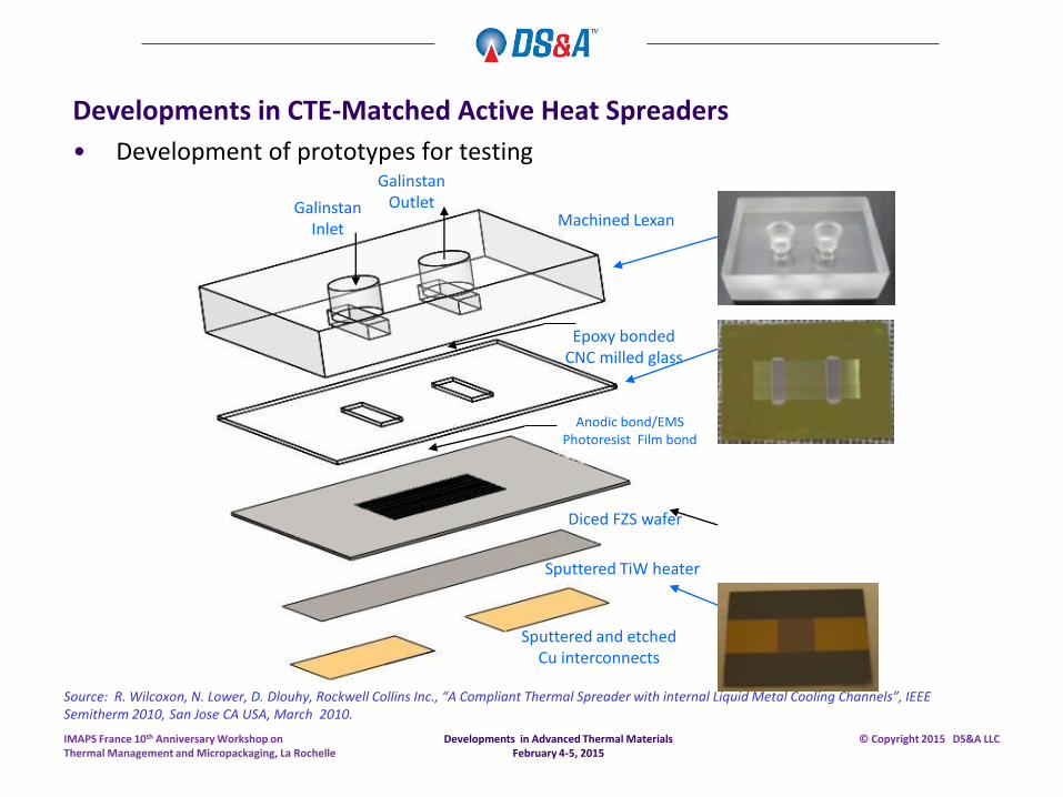
• Development of prototypes for testing
Galinstan Inlet
Machined Lexan
Epoxy bonded CNC milled glass
Anodic bond/EMS Photoresist Film bond
Diced FZS wafer
Sputtered TiW heater
Sputtered and etched Cu interconnects
Galinstan Outlet
Source: R. Wilcoxon, N. Lower, D. Dlouhy, Rockwell Collins Inc., “A Compliant Thermal Spreader with internal Liquid Metal Cooling Channels”, IEEE Semitherm 2010, San Jose CA USA, March 2010.
Developments in Advanced Thermal Materials February 4-5, 2015
IMAPS France 10th Anniversary Workshop on Thermal Management and Micropackaging, La Rochelle
© Copyright 2015 DS&A LLC
Developments in CTE-Matched Active Heat Spreaders
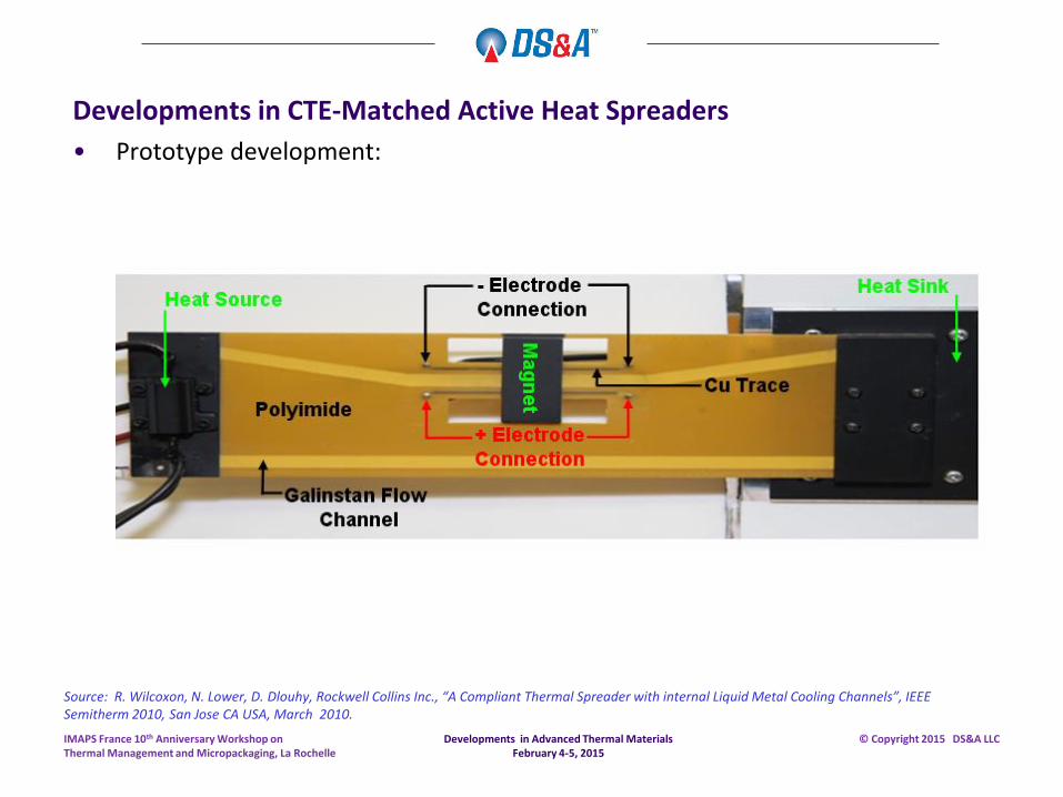
• Prototype development:
Source: R. Wilcoxon, N. Lower, D. Dlouhy, Rockwell Collins Inc., “A Compliant Thermal Spreader with internal Liquid Metal Cooling Channels”, IEEE Semitherm 2010, San Jose CA USA, March 2010.
Developments in Advanced Thermal Materials February 4-5, 2015
IMAPS France 10th Anniversary Workshop on Thermal Management and Micropackaging, La Rochelle
© Copyright 2015 DS&A LLC
Developments in CTE-Matched Active Heat Spreaders
• Continuing development experimental work: Experiments with the optimized geometry in Tuckerman and Pease’s paper has been
repeated and we achieved a thermal resistance of 0.0907oC/W at a heat flux of 835W/cm2.
0.120oC/W thermal resistance in Galinstan-based minichannel cooling was achieved, but at 125 kPa rather than 214 kPa.
0.045oC/W target for Galinstan-based minichannel cooling : final step in testing.
Sources: R. Zhang, M. Hodes, Tufts University; R. Wilcoxon, N. Lower, Rockwell Collins Inc., “High Heat Flux, Single-Phase Microchannel Cooling”, IEEE Semitherm 2014, San Jose CA USA, March 9-13, 2014. R. Wilcoxon, N. Lower, D. Dlouhy, Rockwell Collins Inc., “A Compliant Thermal Spreader with internal Liquid Metal Cooling Channels”, IEEE Semitherm 2010, San Jose CA USA, March 2010.
Developments in Advanced Thermal Materials February 4-5, 2015
IMAPS France 10th Anniversary Workshop on Thermal Management and Micropackaging, La Rochelle
© Copyright 2015 DS&A LLC
Developments in CTE-Matched Active Heat Spreaders
• Continuing development challenges: Microfabrication of test sections compatible with Galinstan, a corrosive liquid metal
CTE mismatches between glass and Lexan sections
Electrical interconnection: 1500W supplied over a 1cm x 1cm heater
Nickel plating for exposed metal parts, plastic wetted pump parts
Oxide formation with Galinstan when exposed to air (requiring vacuum filling).
Developments in Advanced Thermal Materials February 4-5, 2015
IMAPS France 10th Anniversary Workshop on Thermal Management and Micropackaging, La Rochelle
© Copyright 2015 DS&A LLC
Sources: R. Zhang, M. Hodes, Tufts University; R. Wilcoxon, N. Lower, Rockwell Collins Inc., “High Heat Flux, Single-Phase Microchannel Cooling”, IEEE Semitherm 2014, San Jose CA USA, March 9-13, 2014. R. Wilcoxon, N. Lower, D. Dlouhy, Rockwell Collins Inc., “A Compliant Thermal Spreader with internal Liquid Metal Cooling Channels”, IEEE Semitherm 2010, San Jose CA USA, March 2010.
Developments in Thermal Ground Planes
Organization Concept Fluid Reported Apparent
Thermal Conductivity
Reported Power
Density
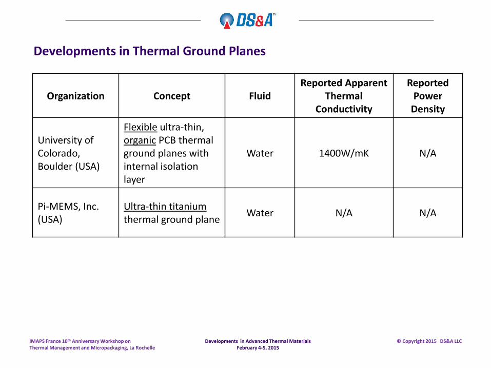
University of Colorado, Boulder (USA)
Flexible ultra-thin, organic PCB thermal ground planes with internal isolation layer
Water 1400W/mK N/A
Pi-MEMS, Inc. (USA)
Ultra-thin titanium thermal ground plane
Water N/A N/A
Developments in Advanced Thermal Materials February 4-5, 2015
IMAPS France 10th Anniversary Workshop on Thermal Management and Micropackaging, La Rochelle
© Copyright 2015 DS&A LLC
Developments in Thermal Ground Planes
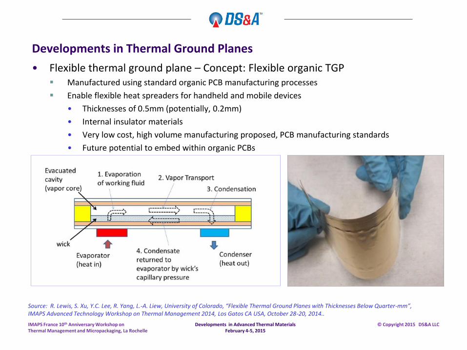
• Flexible thermal ground plane – Concept: Flexible organic TGP Manufactured using standard organic PCB manufacturing processes
Enable flexible heat spreaders for handheld and mobile devices
• Thicknesses of 0.5mm (potentially, 0.2mm)
• Internal insulator materials
• Very low cost, high volume manufacturing proposed, PCB manufacturing standards
• Future potential to embed within organic PCBs
Developments in Advanced Thermal Materials February 4-5, 2015
IMAPS France 10th Anniversary Workshop on Thermal Management and Micropackaging, La Rochelle
© Copyright 2015 DS&A LLC
Source: R. Lewis, S. Xu, Y.C. Lee, R. Yang, L.-A. Liew, University of Colorado, “Flexible Thermal Ground Planes with Thicknesses Below Quarter-mm”, IMAPS Advanced Technology Workshop on Thermal Management 2014, Los Gatos CA USA, October 28-20, 2014..
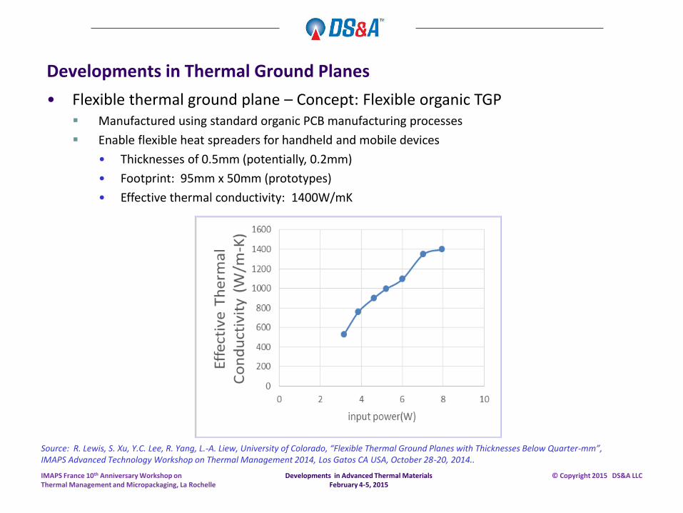
• Flexible thermal ground plane – Concept: Flexible organic TGP Manufactured using standard organic PCB manufacturing processes
Enable flexible heat spreaders for handheld and mobile devices
• Thicknesses of 0.5mm (potentially, 0.2mm)
• Footprint: 95mm x 50mm (prototypes)
• Effective thermal conductivity: 1400W/mK
Developments in Advanced Thermal Materials February 4-5, 2015
IMAPS France 10th Anniversary Workshop on Thermal Management and Micropackaging, La Rochelle
© Copyright 2015 DS&A LLC
Source: R. Lewis, S. Xu, Y.C. Lee, R. Yang, L.-A. Liew, University of Colorado, “Flexible Thermal Ground Planes with Thicknesses Below Quarter-mm”, IMAPS Advanced Technology Workshop on Thermal Management 2014, Los Gatos CA USA, October 28-20, 2014..
Developments in Thermal Ground Planes
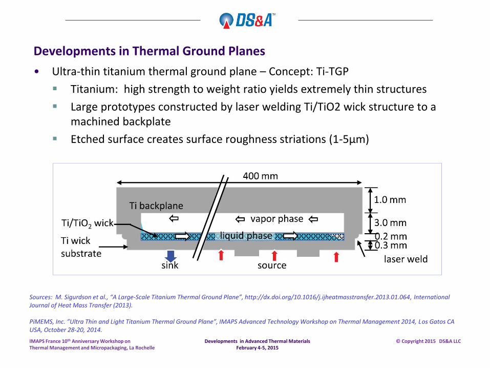
• Ultra-thin titanium thermal ground plane – Concept: Ti-TGP
Titanium: high strength to weight ratio yields extremely thin structures
Large prototypes constructed by laser welding Ti/TiO2 wick structure to a machined backplate
Etched surface creates surface roughness striations (1-5µm)
Developments in Advanced Thermal Materials February 4-5, 2015
IMAPS France 10th Anniversary Workshop on Thermal Management and Micropackaging, La Rochelle
© Copyright 2015 DS&A LLC
Sources: M. Sigurdson et al., “A Large-Scale Titanium Thermal Ground Plane”, http://dx.doi.org/10.1016/j.ijheatmasstransfer.2013.01.064, International Journal of Heat Mass Transfer (2013). PiMEMS, Inc. ”Ultra Thin and Light Titanium Thermal Ground Plane”, IMAPS Advanced Technology Workshop on Thermal Management 2014, Los Gatos CA USA, October 28-20, 2014.
Developments in Thermal Ground Planes
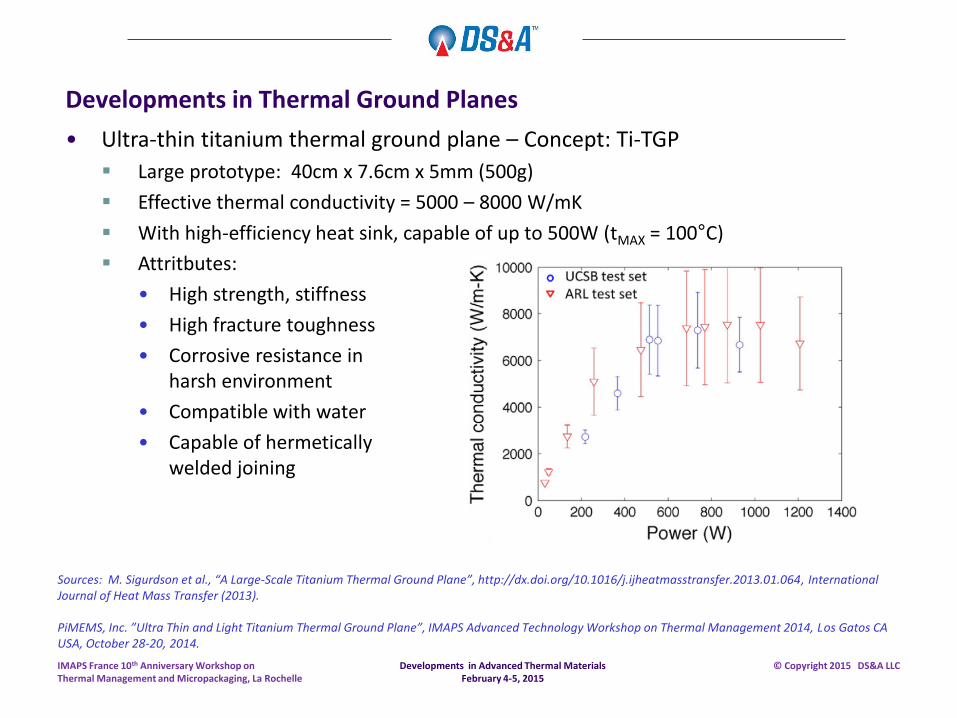
• Ultra-thin titanium thermal ground plane – Concept: Ti-TGP
Large prototype: 40cm x 7.6cm x 5mm (500g)
Effective thermal conductivity = 5000 – 8000 W/mK
With high-efficiency heat sink, capable of up to 500W (tMAX = 100°C)
Attritbutes:
• High strength, stiffness
• High fracture toughness
• Corrosive resistance in harsh environment
• Compatible with water
• Capable of hermetically welded joining
Developments in Advanced Thermal Materials February 4-5, 2015
IMAPS France 10th Anniversary Workshop on Thermal Management and Micropackaging, La Rochelle
© Copyright 2015 DS&A LLC
Sources: M. Sigurdson et al., “A Large-Scale Titanium Thermal Ground Plane”, http://dx.doi.org/10.1016/j.ijheatmasstransfer.2013.01.064, International Journal of Heat Mass Transfer (2013). PiMEMS, Inc. ”Ultra Thin and Light Titanium Thermal Ground Plane”, IMAPS Advanced Technology Workshop on Thermal Management 2014, Los Gatos CA USA, October 28-20, 2014.
Developments in Thermal Ground Planes
• Conformal ultra-thin titanium thermal ground plane – Concept Ti-TGP for handheld devices:
90mm (L) x 20mm (W) x 500µm (Thick)
Weight, finished component: 1.0 – 2.1g
Titanium: high strength to weight ratio
Max. device power: 2.0 – 4.5W@80°C TJ (MAX.)
Developments in Advanced Thermal Materials February 4-5, 2015
IMAPS France 10th Anniversary Workshop on Thermal Management and Micropackaging, La Rochelle
© Copyright 2015 DS&A LLC
Sources: M. Sigurdson et al., “A Large-Scale Titanium Thermal Ground Plane”, http://dx.doi.org/10.1016/j.ijheatmasstransfer.2013.01.064, International Journal of Heat Mass Transfer (2013). PiMEMS, Inc. ”Ultra Thin and Light Titanium Thermal Ground Plane”, IMAPS Advanced Technology Workshop on Thermal Management 2014, Los Gatos CA USA, October 28-20, 2014.
Developments in Thermal Ground Planes
• Conformal ultra-thin titanium thermal ground plane – Concept Ti-TGP for handheld devices
• Titanium vs. copper:
3.2X lighter than copper
5X performance improvement
1.8X improvement in CTE mismatch vs. copper, for silicon die
Developments in Advanced Thermal Materials February 4-5, 2015
IMAPS France 10th Anniversary Workshop on Thermal Management and Micropackaging, La Rochelle
© Copyright 2015 DS&A LLC
Sources: M. Sigurdson et al., “A Large-Scale Titanium Thermal Ground Plane”, http://dx.doi.org/10.1016/j.ijheatmasstransfer.2013.01.064, International Journal of Heat Mass Transfer (2013). PiMEMS, Inc. ”Ultra Thin and Light Titanium Thermal Ground Plane”, IMAPS Advanced Technology Workshop on Thermal Management 2014, Los Gatos CA USA, October 28-20, 2014.
Developments in Thermal Ground Planes
• Cost comparisons
Developments in Advanced Thermal Materials February 4-5, 2015
IMAPS France 10th Anniversary Workshop on Thermal Management and Micropackaging, La Rochelle
© Copyright 2015 DS&A LLC
Developments in Thermal Ground Planes
Developments in CTE-Matched Heat Spreader Composites for GaN RF Semiconductors
Developments in Advanced Thermal Materials February 4-5, 2015
IMAPS France 10th Anniversary Workshop on Thermal Management and Micropackaging, La Rochelle
© Copyright 2015 DS&A LLC
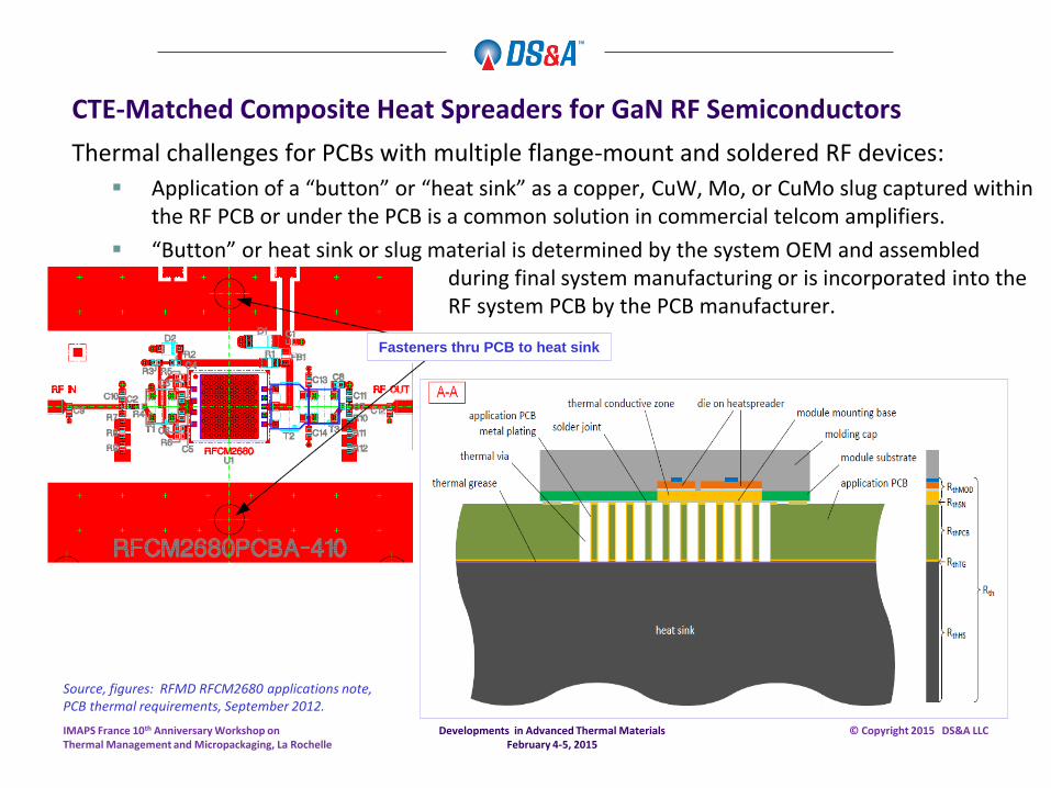
Thermal challenges for PCBs with multiple flange-mount and soldered RF devices:
Application of a “button” or “heat sink” as a copper, CuW, Mo, or CuMo slug captured within the RF PCB or under the PCB is a common solution in commercial telcom amplifiers.
“Button” or heat sink or slug material is determined by the system OEM and assembled during final system manufacturing or is incorporated into the RF system PCB by the PCB manufacturer.
Fasteners thru PCB to heat sink
Source, figures: RFMD RFCM2680 applications note, PCB thermal requirements, September 2012.
Developments in Advanced Thermal Materials February 4-5, 2015
IMAPS France 10th Anniversary Workshop on Thermal Management and Micropackaging, La Rochelle
© Copyright 2015 DS&A LLC
CTE-Matched Composite Heat Spreaders for GaN RF Semiconductors
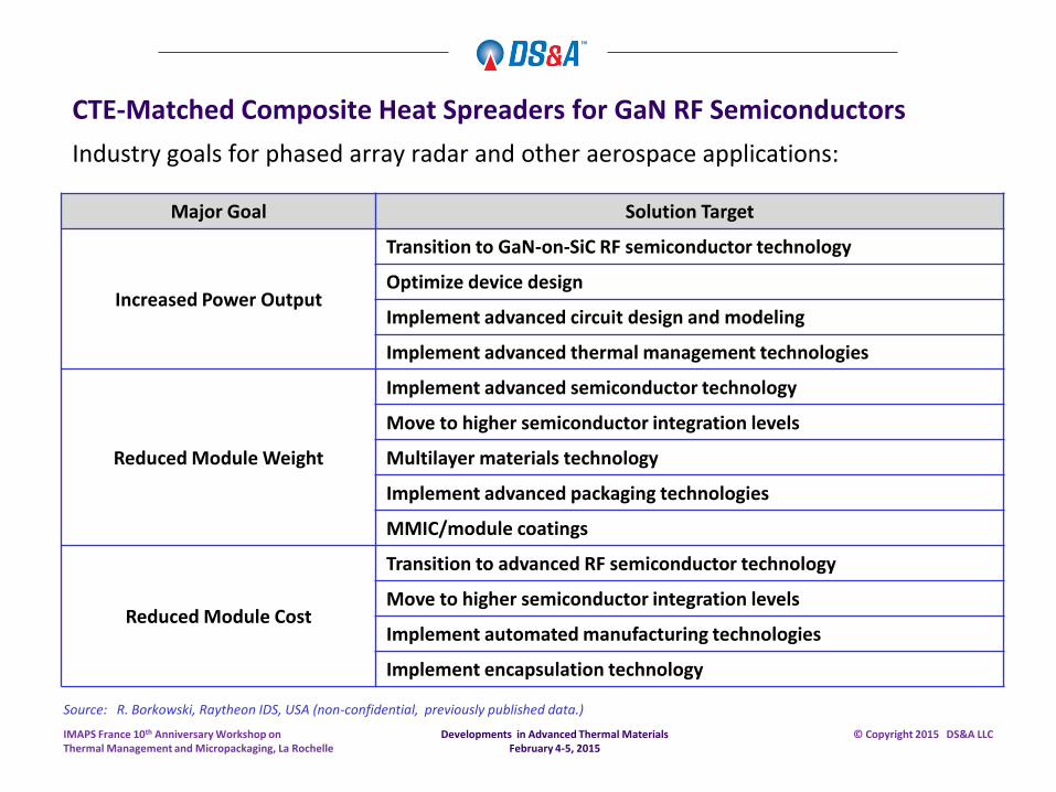
Industry goals for phased array radar and other aerospace applications:
Source: R. Borkowski, Raytheon IDS, USA (non-confidential, previously published data.)
Major Goal Solution Target
Increased Power Output
Transition to GaN-on-SiC RF semiconductor technology
Optimize device design
Implement advanced circuit design and modeling
Implement advanced thermal management technologies
Reduced Module Weight
Implement advanced semiconductor technology
Move to higher semiconductor integration levels
Multilayer materials technology
Implement advanced packaging technologies
MMIC/module coatings
Reduced Module Cost
Transition to advanced RF semiconductor technology
Move to higher semiconductor integration levels
Implement automated manufacturing technologies
Implement encapsulation technology
Developments in Advanced Thermal Materials February 4-5, 2015
IMAPS France 10th Anniversary Workshop on Thermal Management and Micropackaging, La Rochelle
© Copyright 2015 DS&A LLC
CTE-Matched Composite Heat Spreaders for GaN RF Semiconductors
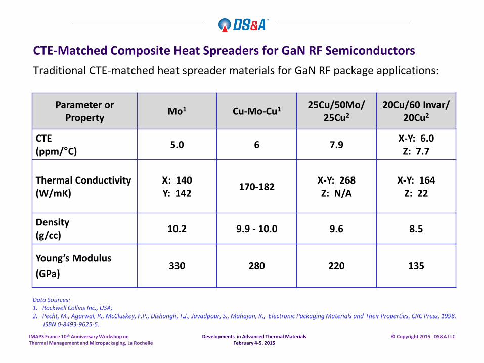
Traditional CTE-matched heat spreader materials for GaN RF package applications:
Parameter or Property
Mo1 Cu-Mo-Cu1 25Cu/50Mo/
25Cu2 20Cu/60 Invar/
20Cu2
CTE (ppm/°C)
5.0 6 7.9 X-Y: 6.0 Z: 7.7
Thermal Conductivity (W/mK)
X: 140 Y: 142
170-182 X-Y: 268 Z: N/A
X-Y: 164 Z: 22
Density (g/cc)
10.2 9.9 - 10.0 9.6 8.5
Young’s Modulus
(GPa) 330 280 220 135
Data Sources: 1. Rockwell Collins Inc., USA; 2. Pecht, M., Agarwal, R., McCluskey, F.P., Dishongh, T.J., Javadpour, S., Mahajan, R., Electronic Packaging Materials and Their Properties, CRC Press, 1998. ISBN 0-8493-9625-5.
Developments in Advanced Thermal Materials February 4-5, 2015
IMAPS France 10th Anniversary Workshop on Thermal Management and Micropackaging, La Rochelle
© Copyright 2015 DS&A LLC
CTE-Matched Composite Heat Spreaders for GaN RF Semiconductors
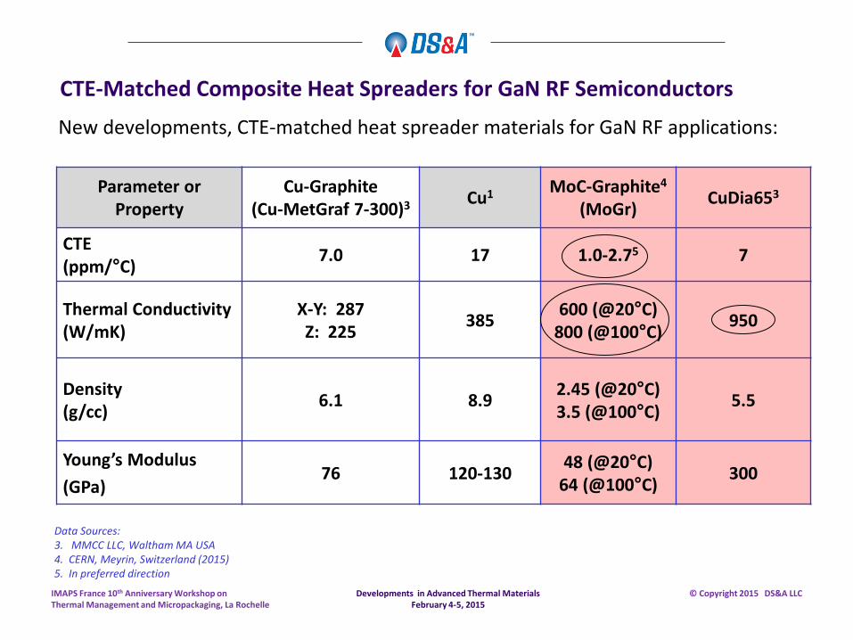
New developments, CTE-matched heat spreader materials for GaN RF applications:
Parameter or Property
Cu-Graphite (Cu-MetGraf 7-300)3
Cu1 MoC-Graphite4
(MoGr) CuDia653
CTE (ppm/°C)
7.0 17 1.0-2.75 7
Thermal Conductivity (W/mK)
X-Y: 287 Z: 225
385 600 (@20°C)
800 (@100°C) 950
Density (g/cc)
6.1 8.9 2.45 (@20°C) 3.5 (@100°C)
5.5
Young’s Modulus
(GPa) 76 120-130
48 (@20°C) 64 (@100°C)
300
Data Sources: 3. MMCC LLC, Waltham MA USA 4. CERN, Meyrin, Switzerland (2015) 5. In preferred direction
Developments in Advanced Thermal Materials February 4-5, 2015
IMAPS France 10th Anniversary Workshop on Thermal Management and Micropackaging, La Rochelle
© Copyright 2015 DS&A LLC
CTE-Matched Composite Heat Spreaders for GaN RF Semiconductors
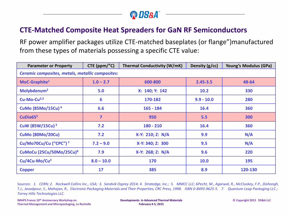
RF power amplifier packages utilize CTE-matched baseplates (or flange”)manufactured from these types of materials possessing a specific CTE value:
Parameter or Property CTE (ppm/°C) Thermal Conductivity (W/mK) Density (g/cc) Young’s Modulus (GPa)
Ceramic composites, metals, metallic composites:
MoC-Graphite1 1.0 – 2.7 600-800 2.45-3.5 48-64
Molybdenum2 5.0 X: 140; Y: 142 10.2 330
Cu-Mo-Cu2,3 6 170-182 9.9 - 10.0 280
CuMo (85Mo/15Cu) 4 6.6 165 - 184 16.4 360
CuDia655 7 950 5.5 300
CuW (85W/15Cu) 3 7.2 180 - 210 16.4 360
CuMo (80Mo/20Cu) 7.2 X-Y: 210; Z: N/A 9.9 N/A
Cu/Mo70Cu/Cu (“CPC”) 7 7.2 – 9.0 X-Y: 340; Z: 300 9.5 N/A
CuMoCu (25Cu/50Mo/25Cu)6 7.9 X-Y: 268; Z: N/A 9.6 220
Cu/4Cu-Mo/Cu3 8.0 – 10.0 170 10.0 195
Copper 17 385 8.9 120-130
Sources: 1. CERN; 2. Rockwell Collins Inc., USA; 3. Sandvik Osprey 2014; 4. Stratedge, Inc.; 5. MMCC LLC; 6Pecht, M., Agarwal, R., McCluskey, F.P., Dishongh, T.J., Javadpour, S., Mahajan, R., Electronic Packaging Materials and Their Properties, CRC Press, 1998. ISBN 0-8493-9625-5. 7. Quantum Leap Packaging LLC.; Torrey Hills Technologies LLC.
Developments in Advanced Thermal Materials February 4-5, 2015
IMAPS France 10th Anniversary Workshop on Thermal Management and Micropackaging, La Rochelle
© Copyright 2015 DS&A LLC
CTE-Matched Composite Heat Spreaders for GaN RF Semiconductors
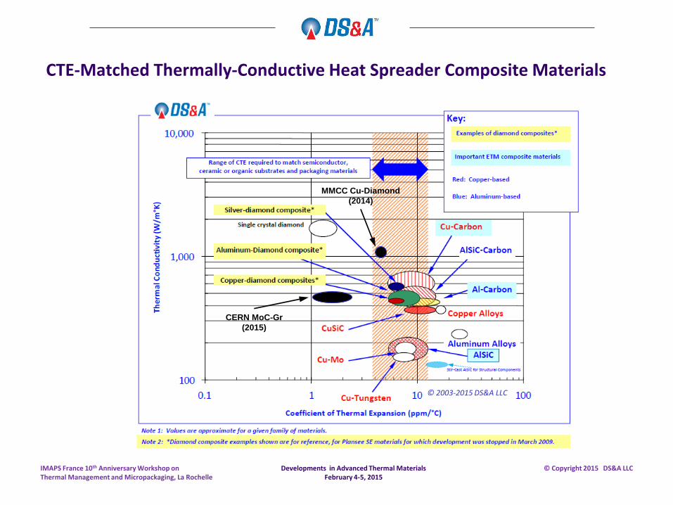
CTE-Matched Thermally-Conductive Heat Spreader Composite Materials
MMCC Cu-Diamond
(2014)
Developments in Advanced Thermal Materials February 4-5, 2015
IMAPS France 10th Anniversary Workshop on Thermal Management and Micropackaging, La Rochelle
© Copyright 2015 DS&A LLC
CERN MoC-Gr
(2015)
© 2003-2015 DS&A LLC
Thermal interface materials, heat spreaders, and CTE-matched high thermal conductivity materials are critical to reliability and product life for electronic systems.
This brief summary attempts to outline recent progress made in a number of areas in advanced thermal materials.
There are many development activities worldwide intended to find new ways to reduce thermal resistance within a semiconductor package or electronic system, and improve system reliability.
Please request additional references to technical manuscripts and sources, if interested.
Thank you.
Developments in Advanced Thermal Materials February 4-5, 2015
IMAPS France 10th Anniversary Workshop on Thermal Management and Micropackaging, La Rochelle
© Copyright 2015 DS&A LLC
Summary – Advances in Thermal Materials
100 High Street David L. Saums, Principal Amesbury MA 01913 USA E: [email protected] Tel: +1 978 499 4990 Website: www.dsa-thermal.com
Business and product development strategy for electronics thermal management: advanced thermal materials, components, and thermal systems.
Contact Information
© Copyright 2015 DS&A LLC
Developments in Advanced Thermal Materials February 4-5, 2015
IMAPS France 10th Anniversary Workshop on Thermal Management and Micropackaging, La Rochelle