Embed Size (px)
Citation preview
04.11 -
03.1351209061
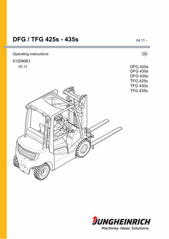
DFG / TFG 425s - 435s
Operating instructions G
DFG 430sDFG 435sTFG 425sTFG 430sTFG 435s
DFG 425s

3
03.1
3 E
NDeclaration of Conformity
Jungheinrich AG, Am Stadtrand 35, D-22047 HamburgManufacturer or agent acting in the European Union
Additional information
On behalf of
Date
G EU Conformity DeclarationThe undersigned hereby declare that the powered industrial truck described below indetail complies with the European Directives 2006/42/EC (Machinery Directive) and2004/108/EEC (Electromagnetic Compatibility - EMC) including amendments as wellas the legislative decree to incorporate the directives in national law. The signatoriesare in each case individually authorized to compile the technical documents.
Type Option Serial no. Year of manufacture
DFG 425s DFG 430s DFG 435s TFG 425s TFG 430s TFG 435s
G

03.1
3 E
N
4
5
03.1
3 E
NForewordNotes on the operating instructionsThe present ORIGINAL OPERATING INSTRUCTIONS are designed to providesufficient instruction for the safe operation of the industrial truck. The information isprovided clearly and concisely. The chapters are arranged by letter and the pages arenumbered continuously.
The operator manual details different industrial truck models. When operating andservicing the industrial truck, make sure that the particular section applies to your truckmodel.
Our trucks are subject to ongoing development. Jungheinrich reserves the right toalter the design, equipment and technical features of the system. No guarantee ofparticular features of the truck should therefore be assumed from the presentoperating instructions.
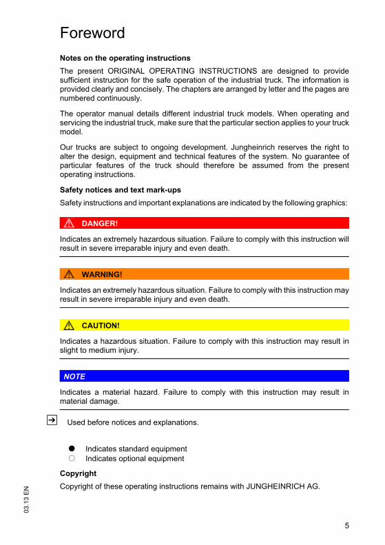
Safety notices and text mark-upsSafety instructions and important explanations are indicated by the following graphics:
DANGER!
Indicates an extremely hazardous situation. Failure to comply with this instruction willresult in severe irreparable injury and even death.
WARNING!
Indicates an extremely hazardous situation. Failure to comply with this instruction mayresult in severe irreparable injury and even death.
CAUTION!
Indicates a hazardous situation. Failure to comply with this instruction may result inslight to medium injury.
NOTE
Indicates a material hazard. Failure to comply with this instruction may result inmaterial damage.
Z Used before notices and explanations.
CopyrightCopyright of these operating instructions remains with JUNGHEINRICH AG.
t Indicates standard equipmento Indicates optional equipment

03.1
3 E
N
6
Jungheinrich AktiengesellschaftAm Stadtrand 3522047 Hamburg - Germany
Tel: +49 (0) 40/6948-0
www.jungheinrich.com
7
03.1
3 E
NContents
A Correct Use and Application .................................................... 11
1 General.................................................................................................... 112 Correct application................................................................................... 113 Approved application conditions.............................................................. 124 Proprietor responsibilities ........................................................................ 135 Adding attachments and/or optional equipment ...................................... 13
B Truck Description ..................................................................... 15
1 Application............................................................................................... 151.1 Truck models and rated capacity............................................................. 152 Assemblies and Functional Description................................................... 162.1 Travel direction definition......................................................................... 162.2 Assembly Overview................................................................................. 172.3 Functional Description............................................................................. 183 Technical Specifications.......................................................................... 203.1 Performance data.................................................................................... 203.2 Dimensions.............................................................................................. 223.3 Weights ................................................................................................... 243.4 Mast versions .......................................................................................... 253.5 Tyre type ................................................................................................. 273.6 Engine Data............................................................................................. 273.7 EN norms................................................................................................. 283.8 Conditions of use..................................................................................... 283.9 Electrical requirements ............................................................................ 294 Identification points and data plates ........................................................ 304.1 Data plate ................................................................................................ 324.2 Truck capacity plate................................................................................. 334.3 Attachment capacity plate ....................................................................... 345 Stability .................................................................................................... 34
C Transport and Commissioning ................................................. 35
1 Transport ................................................................................................. 352 Loading the Truck.................................................................................... 352.1 Centre of gravity of the truck ................................................................... 352.2 Lifting the truck by crane ......................................................................... 362.3 Loading with another industrial truck ....................................................... 373 Securing the truck during transport ......................................................... 384 Using the Truck for the First Time ........................................................... 39
03.1
3 E
N
8
D Fuelling the Truck .................................................................... 41
1 General.................................................................................................... 411.1 Safety regulations for handling diesel fuel and LPG................................ 411.2 LPG system relief valve........................................................................... 432 Adding diesel ........................................................................................... 442.1 Fuelling.................................................................................................... 442.2 Fuelling with fuel containers .................................................................... 463 LPG containers........................................................................................ 473.1 LPG bottles.............................................................................................. 473.2 Liquid gas tank ........................................................................................ 504 Fuel level indicator................................................................................... 514.1 Display unit .............................................................................................. 514.2 Level indicator for LPG bottles (o).......................................................... 51
E Operation ................................................................................. 53
1 Safety Regulations for the Operation of the Forklift Truck....................... 532 Displays and Controls.............................................................................. 552.1 Control panel with display unit................................................................. 582.2 Control panel buttons .............................................................................. 612.3 Display..................................................................................................... 643 Preparing the Truck for Operation ........................................................... 653.1 Checks and operations to be performed before starting daily operation . 653.2 Entry and exit .......................................................................................... 673.3 Trucks with reduced headroom (o) ........................................................ 673.4 Setting up the operator position............................................................... 683.5 Seat Belt .................................................................................................. 734 Industrial Truck Operation ....................................................................... 744.1 Safety regulations for truck operation...................................................... 744.2 Preparing the truck for operation ............................................................. 764.3 Starting procedure for the DFG ............................................................... 774.4 Starting procedure for the TFG................................................................ 784.5 Parking the truck securely ....................................................................... 794.6 Emergency Disconnect............................................................................ 804.7 Travel ...................................................................................................... 814.8 Steering ................................................................................................... 834.9 Brakes ..................................................................................................... 834.10 Setting the time ....................................................................................... 874.11 Adjusting the forks ................................................................................... 884.12 Replacing the forks.................................................................................. 894.13 Lifting, transporting and depositing loads................................................ 904.14 Operating the lift mechanism and integrated attachments ...................... 924.15 Safety instructions for operating additional attachments ......................... 984.16 Operating additional attachments for the SOLO-PILOT.......................... 1014.17 Operating additional attachments for the MULTI-PILOT ......................... 1034.18 Fitting additional attachments.................................................................. 1055 Towing trailers ......................................................................................... 1086 Optional equipment ................................................................................. 1106.1 Keypad (CanCode) (o) ........................................................................... 1106.2 Assistance systems................................................................................. 129
9
03.1
3 E
N6.3 Steel cab ................................................................................................. 1316.4 Sliding windows....................................................................................... 1316.5 Gate......................................................................................................... 1326.6 Panel door ............................................................................................... 1336.7 Operator position extension..................................................................... 1336.8 Heating and air conditioning system........................................................ 1346.9 Driver’s seat heating / backrest extension............................................... 1376.10 Removable load backrest ........................................................................ 1386.11 Lift cutout override................................................................................... 1386.12 Sideshifter centre position ....................................................................... 1396.13 Fire extinguisher ...................................................................................... 1396.14 Tilt angle display...................................................................................... 1396.15 Rockinger coupling with hand lever or remote control............................. 1406.16 Camera system ....................................................................................... 1416.17 Optional equipment for working in dusty environments........................... 1426.18 Roof window wiper .................................................................................. 1426.19 Control layout “N” .................................................................................... 1437 Troubleshooting....................................................................................... 1447.1 Troubleshooting....................................................................................... 1447.2 Operating the truck without its own drive system .................................... 149
F Industrial Truck Maintenance................................................... 153
1 Operational Safety and Environmental Protection................................... 1532 Maintenance Safety Regulations............................................................. 1542.1 Working on the electrical system............................................................. 1552.2 Consumables and used parts.................................................................. 1552.3 Wheels .................................................................................................... 1552.4 Lift Chains ............................................................................................... 1562.5 Hydraulic system ..................................................................................... 1562.6 Working in the vicinity of the engine........................................................ 1573 Lubricants and Lubrication Schedule ...................................................... 1583.1 Handling consumables safely.................................................................. 1583.2 Lubrication Schedule ............................................................................... 1603.3 Consumables........................................................................................... 1614 Maintenance and repairs ......................................................................... 1634.1 Preparing the truck for maintenance and repairs .................................... 1634.2 Lifting and jacking up the truck safely...................................................... 1644.3 Opening the rear panel............................................................................ 1644.4 Unlocking the engine bonnet ................................................................... 1654.5 Opening the engine cover ....................................................................... 1664.6 Replacing wheels .................................................................................... 1684.7 Checking the wheel attachments............................................................. 1704.8 Hydraulic system ..................................................................................... 1714.9 Engine maintenance................................................................................ 1744.10 Checking electrical fuses......................................................................... 1884.11 Cleaning .................................................................................................. 1944.12 Starter battery.......................................................................................... 1964.13 Exhaust system ....................................................................................... 1974.14 Restoring the truck to service after maintenance and repairs ................. 1985 Decommissioning the industrial truck ...................................................... 1995.1 Prior to decommissioning ........................................................................ 200

03.1
3 E
N
10
5.2 During decommissioning ......................................................................... 2005.3 Restoring the truck to service after decommissioning ............................. 2016 Safety tests to be performed at intervals and after unusual incidents ..... 2027 Final de-commissioning, disposal............................................................ 2038 Human vibration measurement ............................................................... 2039 Servicing and Inspection ......................................................................... 20410 Maintenance checklist DFG..................................................................... 20510.1 Operating company ................................................................................. 20510.2 Customer service..................................................................................... 20811 Maintenance checklist TFG..................................................................... 21711.1 Operating company ................................................................................. 21711.2 Customer service..................................................................................... 220
11
03.1
3 E
NA Correct Use and Application1 General
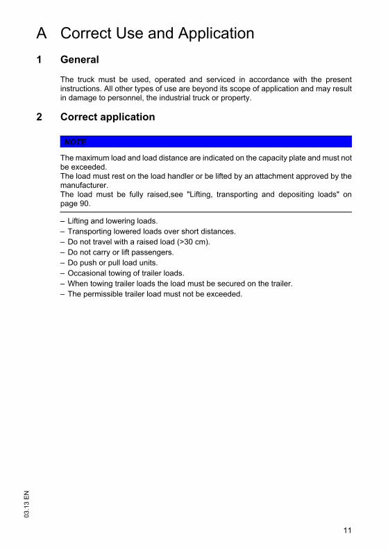
The truck must be used, operated and serviced in accordance with the presentinstructions. All other types of use are beyond its scope of application and may resultin damage to personnel, the industrial truck or property.
2 Correct application
NOTE
The maximum load and load distance are indicated on the capacity plate and must notbe exceeded.The load must rest on the load handler or be lifted by an attachment approved by themanufacturer.The load must be fully raised,see "Lifting, transporting and depositing loads" onpage 90.
– Lifting and lowering loads.– Transporting lowered loads over short distances.– Do not travel with a raised load (>30 cm).– Do not carry or lift passengers.– Do push or pull load units.– Occasional towing of trailer loads.– When towing trailer loads the load must be secured on the trailer.– The permissible trailer load must not be exceeded.
03.1
3 E
N
12
3 Approved application conditions
DANGER!
Do not exceed the permissible surface and point loading on the travel lanes.At blind spots get a second person to assist.The driver must ensure that the loading dock /dock leveller cannot be removed orcome loose during loading/unloading.
– Operation in industrial and commercial environments.– Permissible temperature range -20°C to +40°C.– Operation only on secure, level surfaces with sufficient capacity.– Do not exceed the permissible surface and spot load limits on the travel routes.– Operation only on routes that are visible and approved by the operating company.– Negotiating inclines up to a maximum of 15 %.– Do not travel across or at an angle on inclines. Travel with the load facing uphill.– Operation in partially public traffic.– Do not operate LPG trucks under ground level areas.
WARNING!
Operating an LPG truck under ground level areas could result in explosions.LPG is heavier than air. An explosive LPG/air mixture could therefore form underground level areas without sufficient ventilation.
Do not use LPG trucks under ground level areas.
WARNING!
Use under extreme conditionsUsing the truck under extreme conditions can result in malfunctions and accidents.
Special equipment and authorisation are required if the truck is to be constantlyused in extreme conditions, especially in dusty or corrosive atmospheres.The truck cannot be used in areas at risk of explosion. In adverse weather conditions (thunder, lightning) the industrial truck must not beoperated outside or in endangered areas.
13
03.1
3 E
N4 Proprietor responsibilities
For the purposes of the present operating instructions the “operating company” isdefined as any natural or legal person who either uses the industrial truck himself, oron whose behalf it is used. In special cases (e.g. leasing or renting) the proprietor isconsidered the person who, in accordance with existing contractual agreementsbetween the owner and user of the industrial truck, is charged with operational duties.The proprietor must ensure that the industrial truck is used only for the purpose it isintended for and that danger to life and limb of the user and third parties are excluded.Furthermore, accident prevention regulations, safety regulations and operating,servicing and repair guidelines must be followed. The operating company mustensure that all users have read and understood these operating instructions.
NOTE
Failure to comply with the operating instructions invalidates the warranty. The sameapplies if improper work is carried out on the truck by the customer or third partieswithout the permission of the manufacturer.
5 Adding attachments and/or optional equipment
The mounting or installation of additional equipment which affects or enhances theperformance of the industrial truck requires the written permission of themanufacturer. Local authority approval may also need to be obtained.Local authority approval however does not constitute the manufacturer’s approval.

03.1
3 E
N
14
15
03.1
3 E
NB Truck Description1 Application
The DFG / TFG 425s - 435s is a four-wheel sit-down industrial truck with a combustionengine. The DFG series are diesel engine trucks, while the TFG series are fitted witha petrol engine for LPG operation.
The DFG / TFG 425s - 435s is a cantilever counterbalanced truck which can lift,transport and deposit loads using the load handler attached in front.
The DFG / TFG 425s - 435s is equipped with a hydrostatic drive. The combustionengine drives high pressure pumps for the hydraulic functions and two hydraulicmotors to drive the wheels.
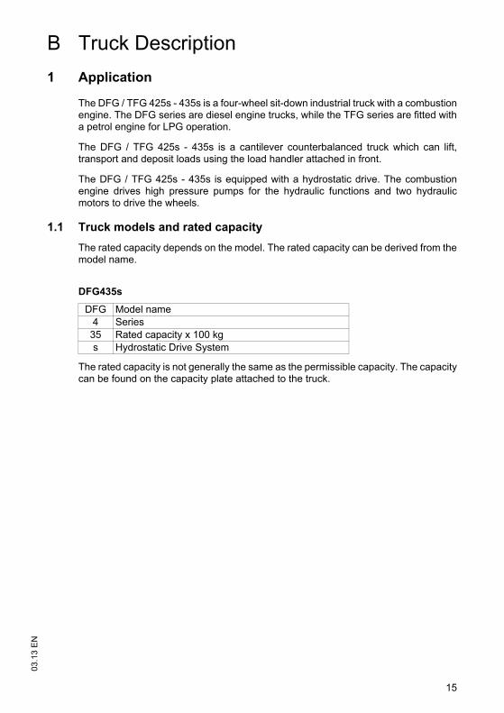
1.1 Truck models and rated capacityThe rated capacity depends on the model. The rated capacity can be derived from themodel name.
The rated capacity is not generally the same as the permissible capacity. The capacitycan be found on the capacity plate attached to the truck.
DFG435s
DFG Model name4 Series35 Rated capacity x 100 kgs Hydrostatic Drive System
03.1
3 E
N
16
2 Assemblies and Functional Description
2.1 Travel direction definition
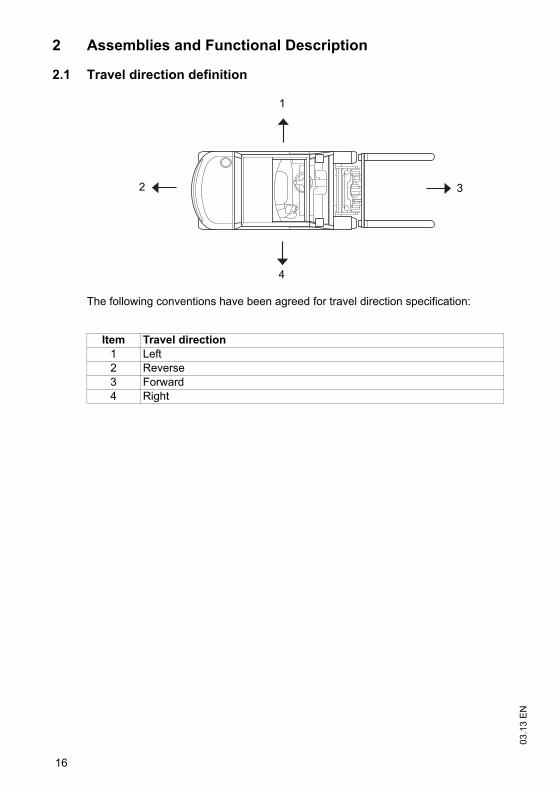
The following conventions have been agreed for travel direction specification:
Item Travel direction1 Left2 Reverse3 Forward4 Right
1
3
4
2
17
03.1
3 E
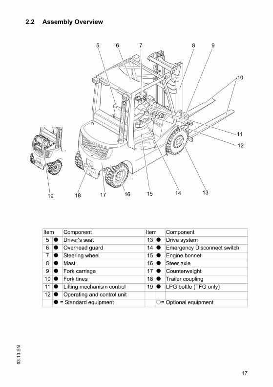
N2.2 Assembly Overview
Item Component Item Component5 t Driver's seat 13 t Drive system6 t Overhead guard 14 t Emergency Disconnect switch7 t Steering wheel 15 t Engine bonnet8 t Mast 16 t Steer axle9 t Fork carriage 17 t Counterweight10 t Fork tines 18 t Trailer coupling11 t Lifting mechanism control 19 t LPG bottle (TFG only)12 t Operating and control unit
t = Standard equipment o= Optional equipment
5
11
12
14
10
131618 17 1519
6 7 8 9
03.1
3 E
N
18
2.3 Functional DescriptionChassisThe chassis, in conjunction with the counterweight, forms the supporting basestructure of the truck. It is used to support the main components.
The hydraulic oil reservoir is integrated on the right-hand side and the fuel tank for theDFG series is on the left side in the chassis.
Operator position and overhead guardThe overhead guard (6) comes in a range of models and protects the driver fromfalling objects and other external influences.
All the controls are ergonomically arranged. The steering column and driver's seat canbe adjusted individually.
The controls and warnings on the display unit (12) enable the system to be monitoredduring operation, thereby ensuring a very high level of safety.
SteeringThe steer cylinder of the hydrostatic steering is integrated in the steer axle (16) and iscontrolled by the power steering. The steer axle is fully floating in the chassis toensure excellent grip even on non-level surfaces.
WheelsAll wheels are located within the truck geometry. A choice of pneumatic orsuperelastic tyres are available.
EngineHigh performance, water-cooled diesel and LPG engines with long useful lives andlow consumption and emission levels.
Electrical System12-volt system with 3-phase alternator. A repeat start block prevents malfunctionswhen the truck is powered up. For diesel engines, a rapid pre-heat system is installed;LPG motors have an electronic ignition system for rapid and trouble-free enginestarting. The key switch is used to start and stop the engine.
19
03.1
3 E
N
Drive system and brakesBoth drive wheels are powered by individual hydraulic motors which in turn are drivenby a hydraulic pump. Forward/reverse or neutral can be set with the travel directionswitch on the control panel (11).
The truck brakes to a halt via the hydraulic motors (service brake), keeping energyconsumption to a minimum. The truck can brake more quickly if you also apply theemergency stop brake.
The parking brake is an automatic multi-plate brake that can also be applied manually.
Hydraulic systemA MULTI-PILOT valve allows for sensitive operation of the functions via the controls.A speed-controlled hydraulic pump ensures a proportionate and efficient supply to thehydraulic functions.
MastTwo or three-stage masts, optionally with free lift function; narrow mast sectionsensure excellent visibility of the forks and attachments. Fork carriage and mast run onpermanently lubricated and hence maintenance-free support rollers.
AttachmentsThe trucks can be optionally fitted with mechanical and hydraulic attachments.
03.1
3 E
N
20
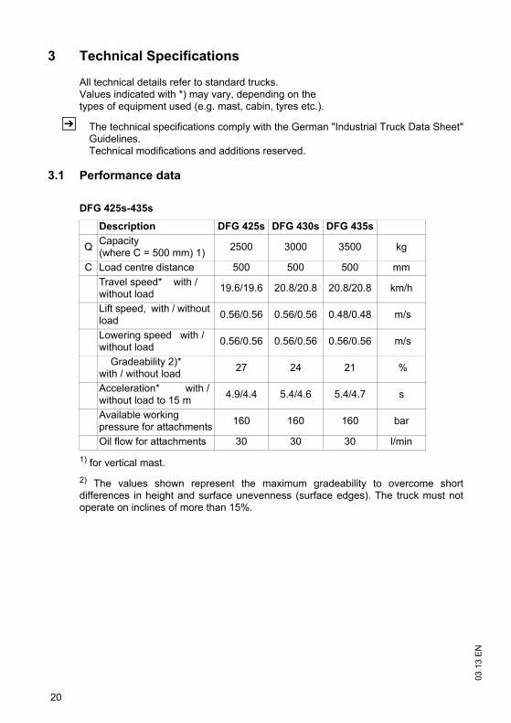
3 Technical Specifications
All technical details refer to standard trucks.Values indicated with *) may vary, depending on the types of equipment used (e.g. mast, cabin, tyres etc.).
Z The technical specifications comply with the German "Industrial Truck Data Sheet"Guidelines. Technical modifications and additions reserved.
3.1 Performance data
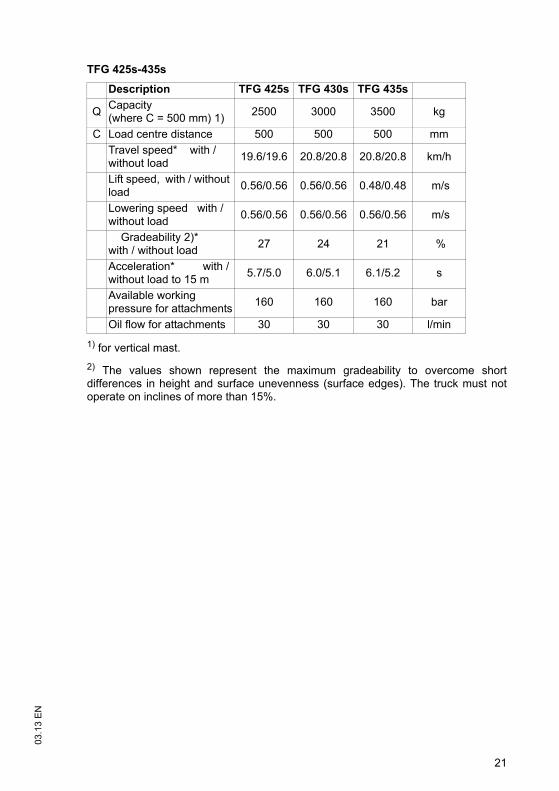
1) for vertical mast.2) The values shown represent the maximum gradeability to overcome shortdifferences in height and surface unevenness (surface edges). The truck must notoperate on inclines of more than 15%.
DFG 425s-435s
Description DFG 425s DFG 430s DFG 435s
Q Capacity (where C = 500 mm) 1) 2500 3000 3500 kg
C Load centre distance 500 500 500 mmTravel speed* with / without load 19.6/19.6 20.8/20.8 20.8/20.8 km/h
Lift speed, with / without load 0.56/0.56 0.56/0.56 0.48/0.48 m/s
Lowering speed with / without load 0.56/0.56 0.56/0.56 0.56/0.56 m/s
Gradeability 2)* with / without load 27 24 21 %
Acceleration* with / without load to 15 m 4.9/4.4 5.4/4.6 5.4/4.7 s
Available working pressure for attachments 160 160 160 bar
Oil flow for attachments 30 30 30 l/min
21
03.1
3 E
N
1) for vertical mast.2) The values shown represent the maximum gradeability to overcome shortdifferences in height and surface unevenness (surface edges). The truck must notoperate on inclines of more than 15%.
TFG 425s-435s
Description TFG 425s TFG 430s TFG 435s
Q Capacity (where C = 500 mm) 1) 2500 3000 3500 kg
C Load centre distance 500 500 500 mmTravel speed* with / without load 19.6/19.6 20.8/20.8 20.8/20.8 km/h
Lift speed, with / without load 0.56/0.56 0.56/0.56 0.48/0.48 m/s
Lowering speed with / without load 0.56/0.56 0.56/0.56 0.56/0.56 m/s
Gradeability 2)* with / without load 27 24 21 %
Acceleration* with / without load to 15 m 5.7/5.0 6.0/5.1 6.1/5.2 s
Available working pressure for attachments 160 160 160 bar
Oil flow for attachments 30 30 30 l/min
03.1
3 E
N
22
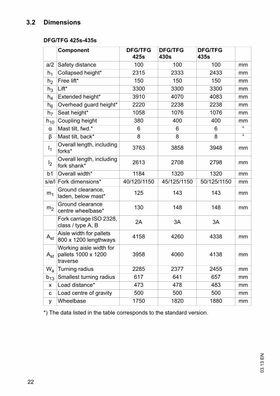
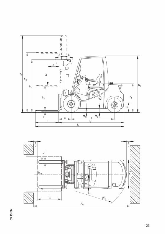
3.2 Dimensions
*) The data listed in the table corresponds to the standard version.
DFG/TFG 425s-435s
Component DFG/TFG 425s
DFG/TFG 430s
DFG/TFG 435s
a/2 Safety distance 100 100 100 mmh1 Collapsed height* 2315 2333 2433 mmh2 Free lift* 150 150 150 mmh3 Lift* 3300 3300 3300 mmh4 Extended height* 3910 4070 4083 mmh6 Overhead guard height* 2220 2238 2238 mmh7 Seat height* 1058 1076 1076 mmh10 Coupling height 380 400 400 mm
Mast tilt, fwd.* 6 6 6 °Mast tilt, back* 8 8 8 °
l1Overall length, including forks* 3763 3858 3948 mm
l2Overall length, including fork shank* 2613 2708 2798 mm
b1 Overall width* 1184 1320 1320 mms/e/l Fork dimensions* 40/120/1150 45/125/1150 50/125/1150 mm
m1Ground clearance, laden, below mast* 125 143 143 mm
m2Ground clearance centre wheelbase* 130 148 148 mm
Fork carriage ISO 2328, class / type A, B 2A 3A 3A
AstAisle width for pallets 800 x 1200 lengthways 4158 4260 4338 mm
Ast
Working aisle width for pallets 1000 x 1200 traverse
3958 4060 4138 mm
Wa Turning radius 2285 2377 2455 mmb13 Smallest turning radius 617 641 657 mmx Load distance* 473 478 483 mmc Load centre of gravity 500 500 500 mmy Wheelbase 1750 1820 1880 mm
23
03.1
3 E
N

03.1
3 E
N
24
3.3 WeightsZ All dimensions in kg.
*) The data listed in the table corresponds to the standard version.
DFG/TFG 425s DFG/TFG 430s DFG/TFG 435sTruck weight* 4080 4376 4821Axle load w.o. load front / rear* 1943 / 2137 1958 / 2488 2009 / 2812Axle load with load front / rear* 5833 / 747 6578 / 868 7339 / 982

25
03.1
3 E
N3.4 Mast versionsZ All dimensions in mm.
DFG/TFG 425s/430s
Mast tableComponent Lift h3 Free lift h2 Retracted
height h1
Extended height h4
Mast weight (kg)
ZT
2900 150 2115 3510/3670 7003100 150 2215 3710/3870 7203300 150 2315 3910/4070 7403500 150 2415 4110/4270 7603700 150 2515 4310/4470 7804000 150 2665 4610/4770 8304300 150 2865 4910/5070 8654500 150 2965 5110/5270 8854700 150 3065 5310/5470 9055000 150 3215 5610/5770 9355500 150 3515 6110/6270 9955800 150 3665 6410/6570 10256000 150 3765 6610/6770 1045
ZZ
2900 1480/1380 2080 3500/3600 7353100 1580/1480 2180 3700/3800 7553300 1680/1580 2280 3900/4000 7803500 1780/1680 2380 4100/4200 8003700 1880/1780 2480 4300/4400 8204000 2030/1930 2630 4600/4700 8504300 2230/2130 2830 4900/5000 9044500 2330/2230 2930 5100/5200 930
DZ
4400 1480/1380 2080 5000/5100 9204700 1580/1480 2180 5300/5400 9505000 1680/1580 2280 5600/5700 9805500 1880/1780 2480 6100/6200 10406000 2080/1980 2680 6600/6700 11006500 2280/2180 2880 7100/7200 11757000 2480/2380 3080 7600/7700 1235
03.1
3 E
N
26
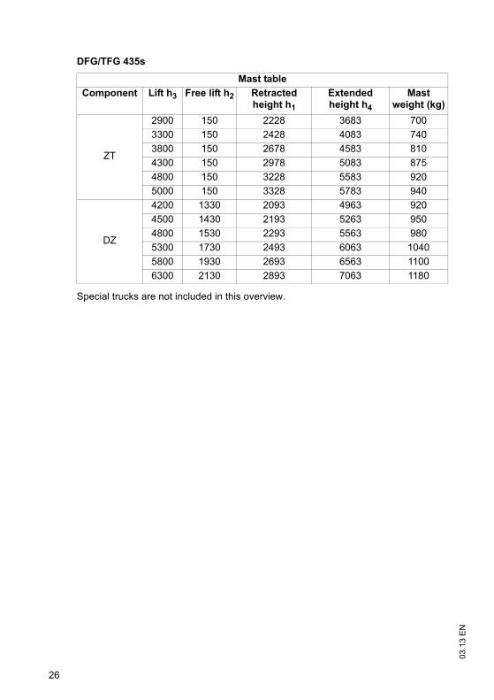
Special trucks are not included in this overview.
DFG/TFG 435s
Mast tableComponent Lift h3 Free lift h2 Retracted
height h1
Extended height h4
Mast weight (kg)
ZT
2900 150 2228 3683 7003300 150 2428 4083 7403800 150 2678 4583 8104300 150 2978 5083 8754800 150 3228 5583 9205000 150 3328 5783 940
DZ
4200 1330 2093 4963 9204500 1430 2193 5263 9504800 1530 2293 5563 9805300 1730 2493 6063 10405800 1930 2693 6563 11006300 2130 2893 7063 1180
27
03.1
3 E
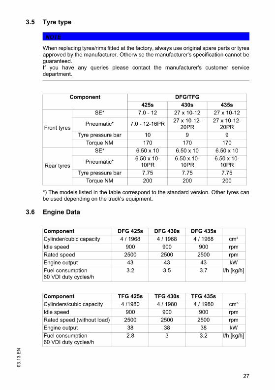
N3.5 Tyre type
NOTE
When replacing tyres/rims fitted at the factory, always use original spare parts or tyresapproved by the manufacturer. Otherwise the manufacturer's specification cannot beguaranteed.If you have any queries please contact the manufacturer's customer servicedepartment.
*) The models listed in the table correspond to the standard version. Other tyres canbe used depending on the truck's equipment.
3.6 Engine Data
Component DFG/TFG425s 430s 435s
Front tyres
SE* 7.0 - 12 27 x 10-12 27 x 10-12
Pneumatic* 7.0 - 12-16PR 27 x 10-12-20PR
27 x 10-12-20PR
Tyre pressure bar 10 9 9Torque NM 170 170 170
Rear tyres
SE* 6.50 x 10 6.50 x 10 6.50 x 10
Pneumatic* 6.50 x 10⁻¹⁰PR
6.50 x 10⁻¹⁰PR
6.50 x 10⁻¹⁰PR
Tyre pressure bar 7.75 7.75 7.75Torque NM 200 200 200
Component DFG 425s DFG 430s DFG 435sCylinder/cubic capacity 4 / 1968 4 / 1968 4 / 1968 cm³Idle speed 900 900 900 rpmRated speed 2500 2500 2500 rpmEngine output 43 43 43 kWFuel consumption60 VDI duty cycles/h
3.2 3.5 3.7 l/h [kg/h]
Component TFG 425s TFG 430s TFG 435sCylinders/cubic capacity 4 /1980 4 / 1980 4 / 1980 cm³Idle speed 900 900 900 rpmRated speed (without load) 2500 2500 2500 rpmEngine output 38 38 38 kWFuel consumption60 VDI duty cycles/h
2.8 3 3.2 l/h [kg/h]
03.1
3 E
N
28
3.7 EN normsNoise emission level
– DFG/TFG 425s/430s: 75 dB(A)– DFG/TFG 435s: 75 dB(A)
*+/- 3 dB(A) depending on the truck's equipment
in accordance with EN 12053 as harmonised with ISO 4871.
Z The noise emission level is calculated in accordance with standard procedures andtakes into account the noise level when travelling, lifting and when idle. The noiselevel is measured at the level of the driver's ear.
Vibration
– DFG/TFG 425s/430s: 0,50 m/s²– DFG/TFG 435s: 0,50 m/s²
in accordance with EN 13059.
Z The internal accuracy of the measuring chain for at 21°C at ± 0,02 m/s². Furtherdeviations may occur in particular through the positioning of the sensor and differentdriver weights.
Z The vibration acceleration acting on the body in the operating position is, inaccordance with standard procedures, the linearly integrated, weightedacceleration in the vertical direction. It is calculated when travelling over thresholdsat constant speed (standard truck version). These recordings were taken on asingle occasion and must not be confused with the human vibrations of the "2002/44/EC/Vibrations" operator directive. The manufacturer offers a special service tomeasure these human vibrations, see "Human vibration measurement" onpage 203.
Electromagnetic compatibility (EMC)The manufacturer confirms that the truck adheres to the limits for electromagneticemissions and resistance as well as the static electricity discharge test in accordancewith EN 12895 as well as the standardised instructions contained therein.
Z No changes to electric or electronic components or their arrangement may be madewithout the written agreement of the manufacturer.
WARNING!
Medical equipment can be damaged by non-ionised radiationElectrical equipment on the truck emitting non-ionised radiation (e.g. wireless datatransmission) can affect operators' medical equipment (pacemakers, hearing aidsetc.) and result in malfunctions. Consult with a doctor or the medical equipmentmanufacturer to clarify whether it can be used near the industrial truck.
3.8 Conditions of useAmbient temperature– operating at -20°C to +40°C
29
03.1
3 E
NZ Special equipment and authorisation are required if the truck is to be used
continually in conditions of extreme temperature or condensing air humidityfluctuations.
3.9 Electrical requirementsThe manufacturer certifies compliance with the requirements for the design andmanufacture of electrical equipment, according to EN 1175 "Industrial Truck Safety -Electrical Requirements", provided the truck is used according to its purpose.
03.1
3 E
N
30
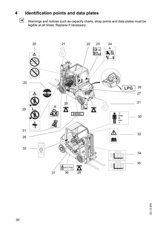
4 Identification points and data plates
Z Warnings and notices such as capacity charts, strap points and data plates must belegible at all times. Replace if necessary.
1211
109
87
6
54
3
2 1
2000
32
20
25
21
31
30
34
35
28
24
33
36
22
21
29
26
26
27
37
23
28
31
03.1
3 E
N
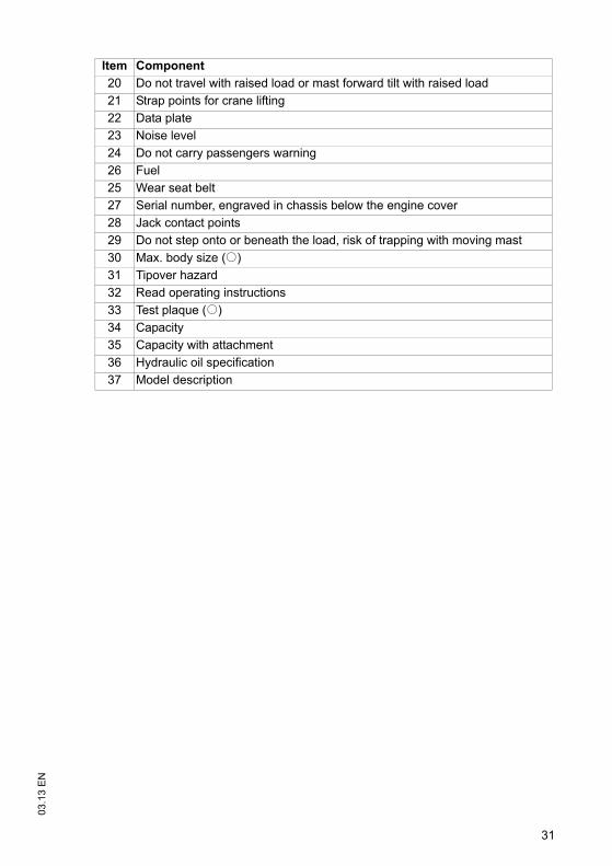
Item Component20 Do not travel with raised load or mast forward tilt with raised load21 Strap points for crane lifting22 Data plate23 Noise level24 Do not carry passengers warning26 Fuel25 Wear seat belt27 Serial number, engraved in chassis below the engine cover28 Jack contact points29 Do not step onto or beneath the load, risk of trapping with moving mast30 Max. body size (o)31 Tipover hazard32 Read operating instructions33 Test plaque (o)34 Capacity35 Capacity with attachment36 Hydraulic oil specification37 Model description
03.1
3 E
N
32
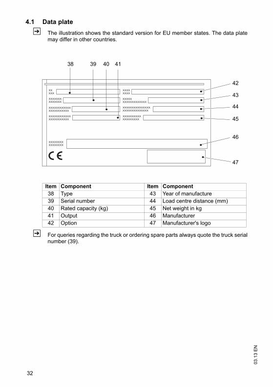
4.1 Data plateZ The illustration shows the standard version for EU member states. The data plate
may differ in other countries.
Z For queries regarding the truck or ordering spare parts always quote the truck serialnumber (39).
Item Component Item Component38 Type 43 Year of manufacture39 Serial number 44 Load centre distance (mm)40 Rated capacity (kg) 45 Net weight in kg41 Output 46 Manufacturer42 Option 47 Manufacturer's logo
38 39 4140
47
44
46
43
42
45
33
03.1
3 E
N4.2 Truck capacity plate
CAUTION!
Accident risk from fork replacement If you replace the forks with ones that differ from the originals, the capacity willchange.
When replacing the forks you must attach an additional capacity plate to the truck.Trucks supplied without forks are given a capacity plate for standard forks (length:1150 mm).
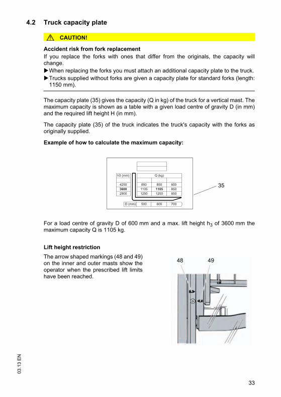
The capacity plate (35) gives the capacity (Q in kg) of the truck for a vertical mast. Themaximum capacity is shown as a table with a given load centre of gravity D (in mm)and the required lift height H (in mm).
The capacity plate (35) of the truck indicates the truck's capacity with the forks asoriginally supplied.
Example of how to calculate the maximum capacity:
For a load centre of gravity D of 600 mm and a max. lift height h3 of 3600 mm themaximum capacity Q is 1105 kg.
Lift height restrictionThe arrow shaped markings (48 and 49)on the inner and outer masts show theoperator when the prescribed lift limitshave been reached.
D (mm) 500 600 700
h3 (mm)
425036002900
85011051250
85011051250
600850850
Q (kg)
35
48 49
03.1
3 E
N
34
4.3 Attachment capacity plateThe attachment capacity plate is next to the truck's capacity plate and gives the truck’scapacity Q (in kg) in conjunction with the respective attachment. The serial number forthe attachment indicated on the capacity plate must match the data plate of theattachment.
5 Stability
The truck's stability has been tested according to latest technological standards.These take into account the dynamic and static tipover forces that can occur if usedcorrectly.
Stability can also be affected by the following factors:– Tyre type– Mast– Attachment– Transported load (size, weight and centre of gravity)
WARNING!
Loss of stability can cause accidentsChanging the components can alter the stability.
35
03.1
3 E
NC Transport and Commissioning1 Transport
Transport can be carried out in two different ways, depending on the height of themast and the local conditions.
– Vertically, with the mast assembled (for low heights)– Vertically, with the mast dismantled (for large heights), all mechanical connections
and hydraulic lines between the basic truck and the mast separated.
2 Loading the Truck
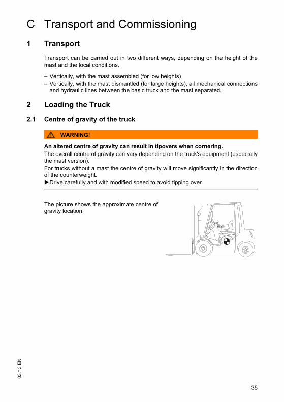
2.1 Centre of gravity of the truck
WARNING!
An altered centre of gravity can result in tipovers when cornering.The overall centre of gravity can vary depending on the truck's equipment (especiallythe mast version). For trucks without a mast the centre of gravity will move significantly in the directionof the counterweight.
Drive carefully and with modified speed to avoid tipping over.
The picture shows the approximate centre ofgravity location.
03.1
3 E
N
36
2.2 Lifting the truck by crane
CAUTION!
The mast can get damagedLoading by crane is only intended for the initial transport before the truck is used forthe first time.Loading must be carried out by specially trained staff in accordance withrecommendations contained in Guidelines VDI 2700 and VDI 2703
DANGER!
Crane slings can tear, resulting in accidentsOnly use crane lifting gear with sufficient capacity.Loading weight = Net weight of truck (+ battery weight for electric trucks).The mast must be tilted back fully. The crane lifting gear on the mast must have a minimum clear length of 2 m.Crane slings should be fastened in such a way that they do not come into contactwith any attachments or the overhead guard when lifting.Do not stand under a swaying load.The truck should only be handled by people who are trained in using lifting slingsand tools.Wear safety shoes when lifting the truck by crane.Do not walk into or stand in a hazardous area.Always attach the crane lifting gear to the prescribed strap points and prevent themfrom slipping.
Z Truck net weight: see "Data plate" on page 32.
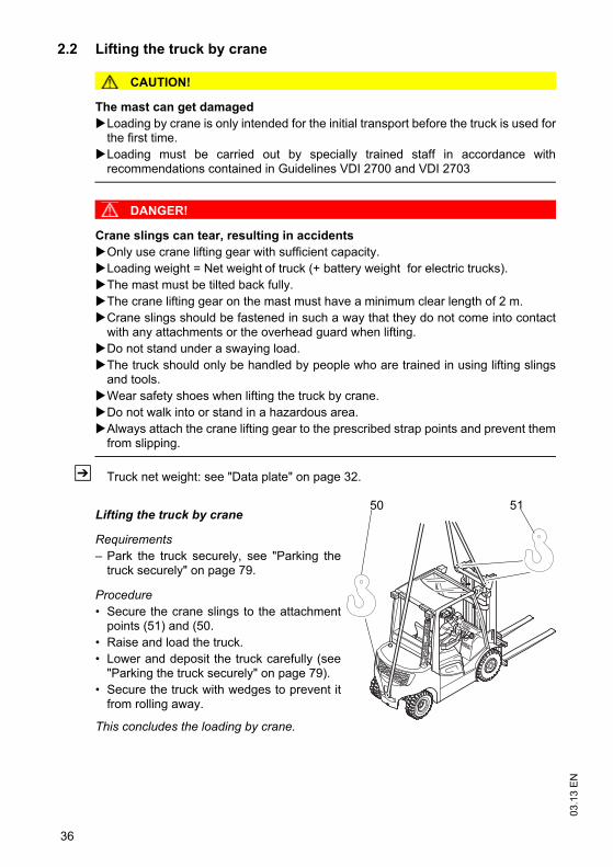
Lifting the truck by crane
Requirements– Park the truck securely, see "Parking the
truck securely" on page 79.
Procedure• Secure the crane slings to the attachment
points (51) and (50.• Raise and load the truck.• Lower and deposit the truck carefully (see
"Parking the truck securely" on page 79).• Secure the truck with wedges to prevent it
from rolling away.
This concludes the loading by crane.
50 51
37
03.1
3 E
N2.3 Loading with another industrial truck
WARNING!
The truck can be damagedThe truck to be loaded can be damaged when loading with another industrial truck.
Only trained specialist personnel should load the truck.Use only trucks with sufficient capacity for loading.Only for loading and unloading.The forks of the second industrial truck must be sufficiently longTransporting over long distances prohibited.
Loading the truck with a second industrial truck
Requirements– Park the truck securely, see "Parking the truck securely" on page 79.
Procedure• Raise the truck with the forks at the side between the axles.• Raise the truck slightly and make sure it is securely positioned on the forks. If
necessary adjust or secure the forks with stops.• Carefully load/unload the truck, see "Lifting, transporting and depositing loads" on
page 90.• Lower the truck slowly onto the ground and prevent it from rolling away.
The truck is now loaded.
03.1
3 E
N
38
3 Securing the truck during transport
WARNING!
Accidental movement during transportImproper fastening of the truck and mast during transport can result in seriousaccidents.
Loading must be carried out by specially trained staff in accordance withrecommendations contained in Guidelines VDI 2700 and VDI 2703 In each casecorrect measurements must be made and appropriate safety measures adopted.The truck must be securely fastened when transported on a lorry or a trailer.The loading area must have clamp rings and a wooden floor to secure the retainingwedges.Use wedges to prevent the truck from moving.Use only tensioning belts or tie-down straps or with sufficient strength.
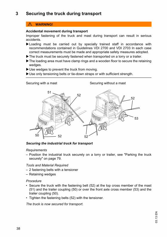
Securing with a mast Securing without a mast
Securing the industrial truck for transport
Requirements– Position the industrial truck securely on a lorry or trailer, see "Parking the truck
securely" on page 79.
Tools and Material Required– 2 fastening belts with a tensioner– Retaining wedges
Procedure• Secure the truck with the fastening belt (52) at the top cross member of the mast
(51) and the trailer coupling (50) or over the front axle cross member (53) and thetrailer coupling (50).
• Tighten the fastening belts (52) with the tensioner.
The truck is now secured for transport.
52
53
50
51
52 52
52
39
03.1
3 E
N4 Using the Truck for the First Time
Safety Instructions for Assembly and Commissioning
WARNING!
Accident risk from incorrect assemblyThe assembly of the truck at the application site, commissioning and driver trainingmust only be performed by the manufacturer's customer service representatives whohave been specially trained for these tasks.
The hydraulic lines may only be connected to the basic truck / mast interface whenthe mast has been properly assembled.Only then can the truck be started.If several trucks have been delivered, make sure that the serial numbers of the loadhandlers, masts and basic trucks always match.
Preparing the truck for operation after delivery or transport
Procedure• Check the equipment is complete.• Check the engine oil level.• Check the hydraulic oil level.• Test the battery connections.• Check the battery acid level (not for maintenance-free batteries).
The truck can now be started, see "Preparing the Truck for Operation" on page 65.

03.1
3 E
N
40
41
03.1
3 E
ND Fuelling the Truck1 General
1.1 Safety regulations for handling diesel fuel and LPG
WARNING!
An unsecured industrial truck can cause accidentsThe truck can suddenly start to move.
Switch off the truck securely before filling up or replacing the LPG bottle, see"Parking the truck securely" on page 79.
WARNING!
Accident risk from ignitionFuels and liquefied petroleum gas can ignite.Smoking, naked flames and other ignition sources are strictly prohibited in theimmediate vicinity when handling fuels and LPG. Labels indicating the hazard are must be positioned where they are clearly visible. Do not store flammable materials in this area. Powder fire extinguisher must be provided within easy reach of the filling area.Use only category A, B or C type powder fire extinguishers to fight LPG fires.Bring any unsealed LPG bottles immediately outside, attach visible markings andnotify the supplier.
Storage and TransportThe diesel and LPG storage and transport devices must comply with statutoryrequirements.
If there is no filling point available, the fuel must be stored and transported in clean,approved containers.
The contents must be clearly indicated on the container.
03.1
3 E
N
42
NOTE
Fuel can cause environmental damageBind any spilled diesel fuel with suitable methods.Then dispose of the diesel and fuel filter in accordance with environmentalregulations.
Fuel filling and LPG bottle replacement personnelPersonnel filling the trucks or replacing LPG bottles must have sufficient knowledgeof the nature of fuels to ensure safe operation.
CAUTION!
Liquid gas can cause frostbiteLiquid gas produces frostbite when it comes into contact with bare skin. Avoid direct contact with the skin.Wear gloves.
Filling up LPG containersLPG containers remain attached to the truck and are filled up at LPG stations. Alwaysfollow the instructions of the tank system and LPG container manufacturer as well asstatutory and local regulations when filling up.
NOTE
Instructions for the safe operation of LPG systemsAll maintenance and repair work on LPG systems and containers should be carriedout by qualified personnel who have been trained to work on LPG systems.The owner must comply with all legal requirements, technical standards and healthand safety regulations applicable to liquid gas.Before starting work, the driver must check that all accessible components of theLPG system are in good working order, in accordance with the regulations of thecountry of use. Do not operate the truck if there is any damage, corrosion, wear or degradation toindividual components of the LPG system.
43
03.1
3 E
N
1.2 LPG system relief valve
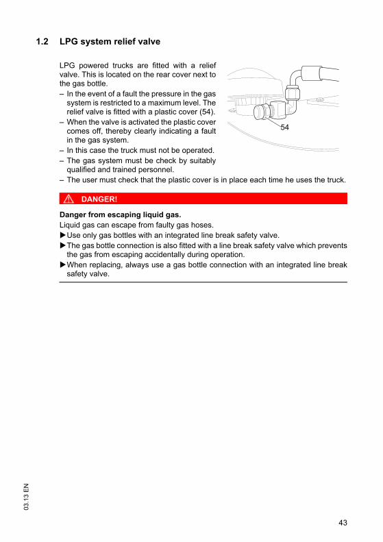
LPG powered trucks are fitted with a reliefvalve. This is located on the rear cover next tothe gas bottle.– In the event of a fault the pressure in the gas
system is restricted to a maximum level. Therelief valve is fitted with a plastic cover (54).
– When the valve is activated the plastic covercomes off, thereby clearly indicating a faultin the gas system.
– In this case the truck must not be operated.– The gas system must be check by suitably
qualified and trained personnel.– The user must check that the plastic cover is in place each time he uses the truck.
DANGER!
Danger from escaping liquid gas.Liquid gas can escape from faulty gas hoses.
Use only gas bottles with an integrated line break safety valve.The gas bottle connection is also fitted with a line break safety valve which preventsthe gas from escaping accidentally during operation.When replacing, always use a gas bottle connection with an integrated line breaksafety valve.
54
03.1
3 E
N
44
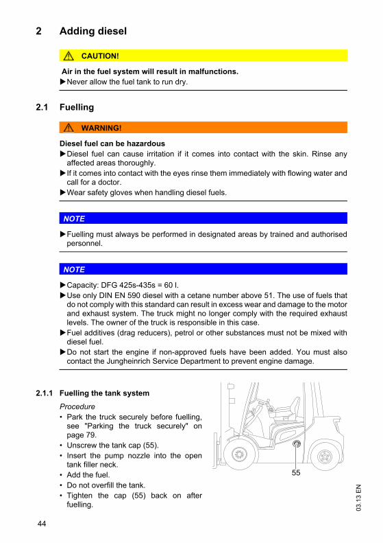
2 Adding diesel
CAUTION!
Air in the fuel system will result in malfunctions.Never allow the fuel tank to run dry.
2.1 Fuelling
WARNING!
Diesel fuel can be hazardousDiesel fuel can cause irritation if it comes into contact with the skin. Rinse anyaffected areas thoroughly. If it comes into contact with the eyes rinse them immediately with flowing water andcall for a doctor.Wear safety gloves when handling diesel fuels.
NOTE
Fuelling must always be performed in designated areas by trained and authorisedpersonnel.
NOTE
Capacity: DFG 425s-435s = 60 l.Use only DIN EN 590 diesel with a cetane number above 51. The use of fuels thatdo not comply with this standard can result in excess wear and damage to the motorand exhaust system. The truck might no longer comply with the required exhaustlevels. The owner of the truck is responsible in this case.Fuel additives (drag reducers), petrol or other substances must not be mixed withdiesel fuel.Do not start the engine if non-approved fuels have been added. You must alsocontact the Jungheinrich Service Department to prevent engine damage.
2.1.1 Fuelling the tank system
Procedure• Park the truck securely before fuelling,
see "Parking the truck securely" onpage 79.
• Unscrew the tank cap (55).• Insert the pump nozzle into the open
tank filler neck.• Add the fuel.• Do not overfill the tank.• Tighten the cap (55) back on after
fuelling.
55

45
03.1
3 E
NFuelling is now complete.
03.1
3 E
N
46
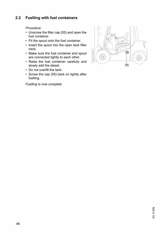
2.2 Fuelling with fuel containers
Procedure• Unscrew the filler cap (55) and open the
fuel container.• Fit the spout onto the fuel container.• Insert the spout into the open tank filler
neck.• Make sure the fuel container and spout
are connected tightly to each other.• Raise the fuel container carefully and
slowly add the diesel.• Do not overfill the tank.• Screw the cap (55) back on tightly after
fuelling.
Fuelling is now complete.
55
47
03.1
3 E
N
3 LPG containers
Z Only use liquid gas that complies with DIN 51622 or comparable nationalregulations.
3.1 LPG bottles
DANGER!
Risk of explosionThe LPG bottle must only be replaced at designated areas by trained andauthorised personnel.
CAUTION!
Using unsuitable LPG bottles can cause accidents.Use only approved LPG bottles. The LPG bottle must always rest on an engaged bottle holder so that the hoseconnection of the shutoff valve is facing vertically down.For bottle types of other countries note the national regulations. Note the indications and markings on the LPG bottle.
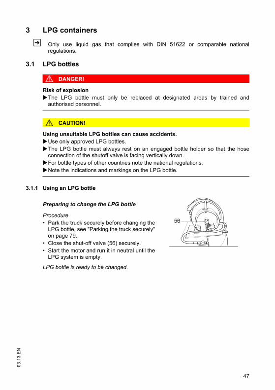
3.1.1 Using an LPG bottle
Preparing to change the LPG bottle
Procedure• Park the truck securely before changing the
LPG bottle, see "Parking the truck securely"on page 79.
• Close the shut-off valve (56) securely.• Start the motor and run it in neutral until the
LPG system is empty.
LPG bottle is ready to be changed.
56
03.1
3 E
N
48
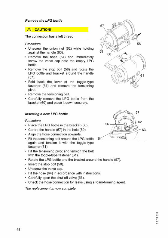
Remove the LPG bottle
CAUTION!
The connection has a left thread
Procedure• Unscrew the union nut (62) while holding
against the handle (63).• Remove the hose (64) and immediately
screw the valve cap onto the empty LPGbottle.
• Remove the stop bolt (58) and rotate theLPG bottle and bracket around the handle(57).
• Fold back the lever of the toggle-typefastener (61) and remove the tensioningpivot.
• Remove the tensioning belt.• Carefully remove the LPG bottle from the
bracket (60) and place it down securely.
Inserting a new LPG bottle
Procedure• Place the LPG bottle in the bracket (60).• Centre the handle (57) in the hole (59).• Align the hose connection upwards.• Fit the tensioning belt around the LPG bottle
again and tension it with the toggle-typefastener (61).
• Fit the tensioning pivot and tension the beltwith the toggle-type fastener (61).
• Rotate the LPG bottle and the bracket around the handle (57).• Insert the stop bolt (58).• Unscrew the valve cap.• Fit the hose (64) in accordance with instructions.• Carefully open the shut-off valve (56).• Check the hose connection for leaks using a foam-forming agent.
The replacement is now complete.
58
57
61
6059
56
64
62
63
57
49
03.1
3 E
N
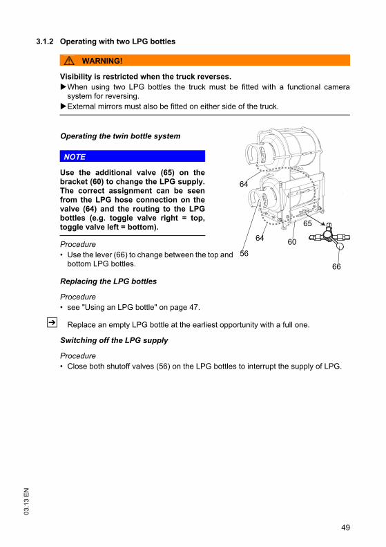
3.1.2 Operating with two LPG bottles
WARNING!
Visibility is restricted when the truck reverses.When using two LPG bottles the truck must be fitted with a functional camerasystem for reversing. External mirrors must also be fitted on either side of the truck.
Operating the twin bottle system
NOTE
Use the additional valve (65) on thebracket (60) to change the LPG supply.The correct assignment can be seenfrom the LPG hose connection on thevalve (64) and the routing to the LPGbottles (e.g. toggle valve right = top,toggle valve left = bottom).
Procedure• Use the lever (66) to change between the top and
bottom LPG bottles.
Replacing the LPG bottles
Procedure• see "Using an LPG bottle" on page 47.
Z Replace an empty LPG bottle at the earliest opportunity with a full one.
Switching off the LPG supply
Procedure• Close both shutoff valves (56) on the LPG bottles to interrupt the supply of LPG.
65
64
64 60
66
56
03.1
3 E
N
50
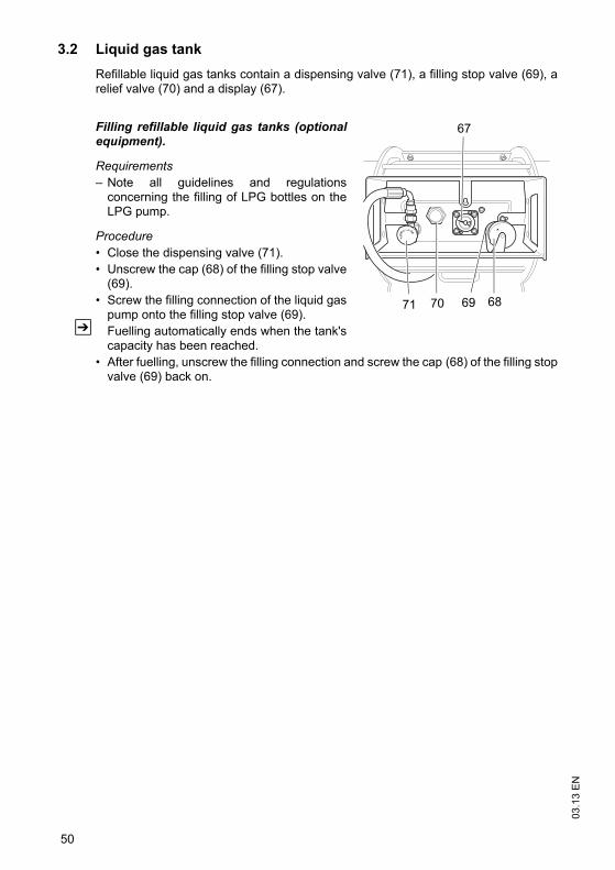
3.2 Liquid gas tankRefillable liquid gas tanks contain a dispensing valve (71), a filling stop valve (69), arelief valve (70) and a display (67).
Filling refillable liquid gas tanks (optionalequipment).
Requirements– Note all guidelines and regulations
concerning the filling of LPG bottles on theLPG pump.
Procedure• Close the dispensing valve (71).• Unscrew the cap (68) of the filling stop valve
(69).• Screw the filling connection of the liquid gas
pump onto the filling stop valve (69).Z Fuelling automatically ends when the tank's
capacity has been reached.• After fuelling, unscrew the filling connection and screw the cap (68) of the filling stop
valve (69) back on.
71 69 6870
67
51
03.1
3 E
N
4 Fuel level indicator
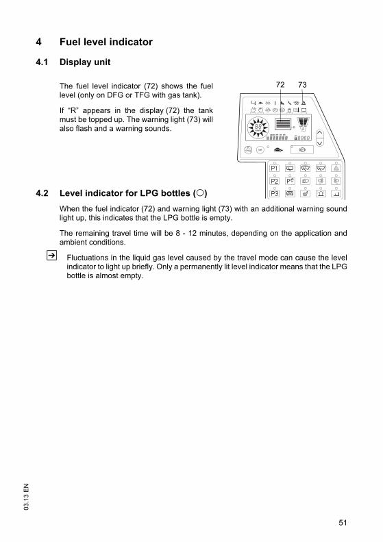
4.1 Display unit
The fuel level indicator (72) shows the fuellevel (only on DFG or TFG with gas tank).
If “R” appears in the display (72) the tankmust be topped up. The warning light (73) willalso flash and a warning sounds.
4.2 Level indicator for LPG bottles (o)When the fuel indicator (72) and warning light (73) with an additional warning soundlight up, this indicates that the LPG bottle is empty.
The remaining travel time will be 8 - 12 minutes, depending on the application andambient conditions.
Z Fluctuations in the liquid gas level caused by the travel mode can cause the levelindicator to light up briefly. Only a permanently lit level indicator means that the LPGbottle is almost empty.
km/h
R
72 73
o

03.1
3 E
N
52
53
03.1
3 E
NE Operation1 Safety Regulations for the Operation of the
Forklift Truck
Driver authorisationThe truck may only be used by suitably trained personnel, who have demonstrated tothe proprietor or his representative that they can drive and handle loads and havebeen authorised to operate the truck by the proprietor or his representative.
Operator’s rights, obligations and responsibilitiesThe operator must be informed of his duties and responsibilities and be instructed inthe operation of the truck and shall be familiar with the operating instructions.
Unauthorised use of truckThe operator is responsible for the truck during the time it is in use. The operator mustprevent unauthorised persons from driving or operating the truck. Do not carrypassengers or lift other people.
Damage and faultsThe supervisor must be informed immediately of any damage or faults to the truck orattachment. Trucks which are unsafe for operation (e.g. wheel or brake problems)must not be used until they have been rectified.
RepairsThe operator must not carry out any repairs or alterations to the truck withoutauthorisation and the necessary training to do so. The operator must never disable oradjust safety mechanisms or switches.
03.1
3 E
N
54
Hazardous area
WARNING!
Risk of accidents/injury in the hazardous area of the truck A hazardous area is defined as the area in which people are at risk due to travel orlifting operations of the truck, its load handler or the load. This also includes the areawithin reach of falling loads or lowering/falling operating equipment.
Instruct unauthorised persons to leave the hazardous area.In case of danger to third parties, give a warning signal in good time.If unauthorised persons are still within the hazardous area, stop the truckimmediately.
WARNING!
Falling objects can cause accidentsFalling objects can injure the operator while the truck is being operated.
The operator must remain within the protected area of the overhead guard while thetruck is being operated.
Safety devices, warning signs and warning instructionsSafety devices, warning signs (see "Identification points and data plates" on page 30)and warning instructions in the present operating instructions must be strictlyobserved.
CAUTION!
Reduced headroom can cause injuriesTrucks with reduced headroom are equipped with a warning label within the operator'sline of sight.
The max. recommended body size indicated on this warning sign must beobserved.The headroom is also reduced when you wear a protective helmet.
55
03.1
3 E
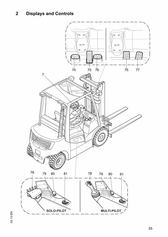
N2 Displays and Controls
SOLO-PILOT MULTI-PILOT
7
7878 8181 8080
75 75 777674
7979
03.1
3 E
N
56
Z *If the truck is equipped with an ISM access module refer to the “ISM AccessModule” operator manual.
Item Control /display
Function
74 “Reverse” accelerator twin pedal control
o The truck reverses when actuated. Provides infinitely variable travel speed.
77 Accelerator pedal t Infinite travel speed control.76 “Forward” accelerator
twin pedal controlo The truck travels forward when actuated.
Provides infinitely variable travel speed.75 Brake pedal t Upon activation, the truck brakes to a halt
immediately.7 Steering wheel t Steers the truck.
78
SOLO-PILOT t Controls the following functions:
– Forward / reverse travel direction (not with dual pedal operation)
– Load handler raise / lower– Mast forward / reverse tilt– Horn button– Sideshifter left / right (o)– Auxiliary hydraulics (o)– Acknowledgement key (o)
MULTI-PILOT
o
79ISM Access Module
oSwitches the truck on*
CanCode80 Emergency Disconnect
switcht Switches control current on and off in
emergencies.
81 Key switch
t Switches current on and off, and starts the engine. Removing the key prevents the truck from being switched on by unauthorized personnel.
t= Series equipment o= Optional equipment
57
03.1
3 E
N
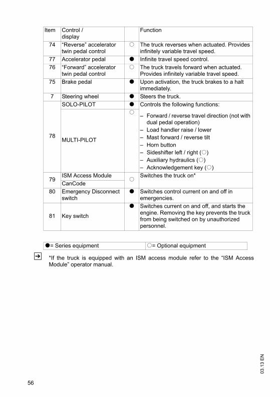
Item Control / display
Function
82 Travel direction switch(not available with dual pedal control)
t Selects travel direction / neutral position.
83 Lever t Lever for operating the hydraulic functions. 84 "Horn" button t Activates an audible warning.85 Additional hydraulic
function release buttono Activates the additional hydraulic functions
or hydraulics that require acknowledgement.
86 Button o Hydraulic auxiliary function control button.
t= Series equipment o= Optional equipment
83 8482
85
8382 84
8486
85
82
03.1
3 E
N
58
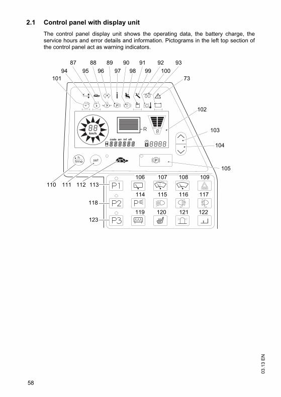
2.1 Control panel with display unitThe control panel display unit shows the operating data, the battery charge, theservice hours and error details and information. Pictograms in the left top section ofthe control panel act as warning indicators.
km/h
R 103
104
105
112111110
123
118
113106 107
120
108 109
114 115 116
119 121 122
117
102
73
93100
9299
919897
8996
8895
87
10194
90
59
03.1
3 E
N
Item Control /display
Function
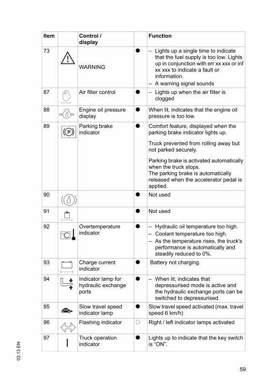
73
WARNING
t – Lights up a single time to indicate that the fuel supply is too low. Lights up in conjunction with err xx xxx or inf xx xxx to indicate a fault or information.
– A warning signal sounds87 Air filter control t – Lights up when the air filter is
clogged
88 Engine oil pressure display
t When lit, indicates that the engine oil pressure is too low.
89 Parking brake indicator
t Comfort feature, displayed when the parking brake indicator lights up.
Truck prevented from rolling away but not parked securely.
Parking brake is activated automatically when the truck stops.The parking brake is automatically released when the accelerator pedal is applied.
90 t Not used
91 t Not used
92 Overtemperature indicator
t – Hydraulic oil temperature too high. – Coolant temperature too high.– As the temperature rises, the truck's
performance is automatically and steadily reduced to 0%.
93 Charge current indicator
t Battery not charging.
94 Indicator lamp for hydraulic exchange ports
t – When lit, indicates that depressurised mode is active and the hydraulic exchange ports can be switched to depressurised.
95 Slow travel speed indicator lamp
t Slow travel speed activated (max. travel speed 6 km/h)
96 Flashing indicator o Right / left indicator lamps activated
97 Truck operation indicator
t Lights up to indicate that the key switch is “ON”.
03.1
3 E
N
60
Z Troubleshooting see "Troubleshooting" on page 144.
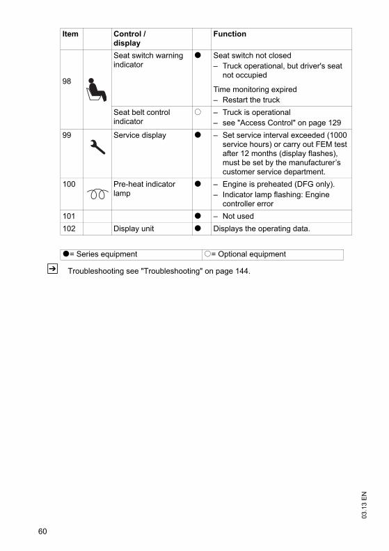
98
Seat switch warning indicator
t Seat switch not closed– Truck operational, but driver's seat
not occupied
Time monitoring expired– Restart the truck
Seat belt control indicator
o – Truck is operational– see "Access Control" on page 129
99 Service display t – Set service interval exceeded (1000 service hours) or carry out FEM test after 12 months (display flashes), must be set by the manufacturer’s customer service department.
100 Pre-heat indicator lamp
t – Engine is preheated (DFG only).– Indicator lamp flashing: Engine
controller error101 t – Not used102 Display unit t Displays the operating data.
t= Series equipment o= Optional equipment
Item Control /display
Function
61
03.1
3 E
N2.2 Control panel buttons
Item Controls and displays
Function
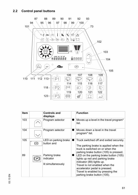
103 Program selector t Moves up a level in the travel program* list.
104 Program selector t Moves down a level in the travel program* list.
105 LED on parking brake button and
t Truck switched off and exited securely.
The parking brake is applied when the truck is switched on or when the parking brake button (105) is pressed. LED on the parking brake button (105) lights up red and parking brake indicator (89) lights up.Travel is not enabled when the accelerator pedal is pressed.Travel is enabled by pressing the parking brake button (105).
89 Parking brake indicator
lit simultaneously
t
km/h
R 103
104
105
112111110
123
118
113106 107
120
108 109
114 115 116
119 121 122
117
102
73
93100
9299
919897
8996
8895
87
10194
90
03.1
3 E
N
62
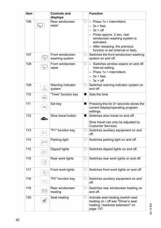
106 Rear windscreen wiper
o – Press 1x > intermittent, – 2x > fast, – 3x > off – Press approx. 2 sec, rear
windscreen washing system is activated.
– After releasing, the previous function is set (interval or fast).
107 Front windscreen washing system
o Switches the front windscreen washing system on and off.
108 Front windscreen wiper
o – Switches window wipers on and off, interval setting.
– Press 1x > intermittent,– 2x > fast, – 3x > off
109 Warning indicator system
o Switches warning indicator system on and off.
110 "Time" function key t Sets the time
111 Set key t Pressing this for 2+ seconds stores the current display/operating program settings.
112 Slow travel button t Switches slow travel on and off.
Slow travel can only be adjusted by Customer Services.
113 "P1" function key o Switches auxiliary equipment on and off.
114 Parking light o Switches parking light on and off.
115 Dipped lights o Switches dipped lights on and off.
116 Rear work lights o Switches rear work lights on and off.
117 Front work lights o Switches front work lights on and off.
118 "P2" function key o Switches auxiliary equipment on and off.
119 Rear windscreen heating
o Switches rear windscreen heating on and off.
120 Seat heating o Activate seat heating (switch seat heating on / off see "Driver’s seat heating / backrest extension" on page 137.
Item Controls and displays
Function
63
03.1
3 E
N
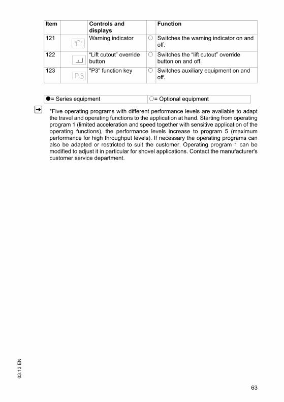
Z *Five operating programs with different performance levels are available to adaptthe travel and operating functions to the application at hand. Starting from operatingprogram 1 (limited acceleration and speed together with sensitive application of theoperating functions), the performance levels increase to program 5 (maximumperformance for high throughput levels). If necessary the operating programs canalso be adapted or restricted to suit the customer. Operating program 1 can bemodified to adjust it in particular for shovel applications. Contact the manufacturer'scustomer service department.
121 Warning indicator o Switches the warning indicator on and off.
122 “Lift cutout” override button
o Switches the “lift cutout” override button on and off.
123 "P3" function key o Switches auxiliary equipment on and off.
t= Series equipment o= Optional equipment
Item Controls and displays
Function
03.1
3 E
N
64
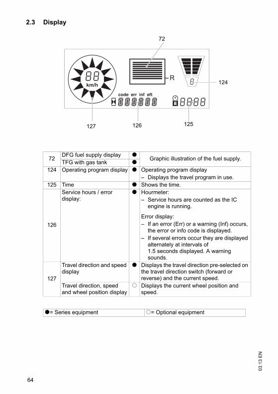
2.3 Display
72 DFG fuel supply display t Graphic illustration of the fuel supply.TFG with gas tank t124 Operating program display t Operating program display
– Displays the travel program in use.125 Time t Shows the time.
126
Service hours / error display:
t Hourmeter:– Service hours are counted as the IC
engine is running.
Error display:– If an error (Err) or a warning (Inf) occurs,
the error or info code is displayed.– If several errors occur they are displayed
alternately at intervals of 1.5 seconds displayed. A warning sounds.
127
Travel direction and speed display
t Displays the travel direction pre-selected on the travel direction switch (forward or reverse) and the current speed.
Travel direction, speed and wheel position display
o Displays the current wheel position and speed.
t= Series equipment o= Optional equipment
km/h
R
72
124
125126127
65
03.1
3 E
N3 Preparing the Truck for Operation
3.1 Checks and operations to be performed before starting daily operation
WARNING!
Damage and other truck or attachment (optional equipment) defects can resultin accidents.If damage or other truck or attachment (optional equipment) defects are discoveredduring the following checks, the truck must be taken out of service until it has beenrepaired.
Report any defects immediately to your supervisor.Mark defective truck and take out of service.Do not return the industrial truck to service until you have identified and rectified thefault.
03.1
3 E
N
66
CAUTION!
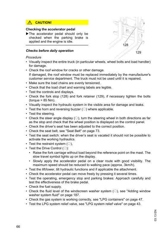
Checking the accelerator pedalThe accelerator pedal should only bechecked when the parking brake isapplied and the engine is idle.
Checks before daily operation
Procedure• Visually inspect the entire truck (in particular wheels, wheel bolts and load handler)
for damage. • Check the roof window for cracks or other damage.
If damaged, the roof window must be replaced immediately by the manufacturer'scustomer service department. The truck must not be used until it is repaired.
• Make sure the load chains are evenly tensioned.• Check that the load chart and warning labels are legible.• Test the controls and displays.• Check the fork stop (128) and fork retainer (129), if necessary tighten the bolts
(torque = 85 Nm).• Visually inspect the hydraulic system in the visible area for damage and leaks.• Test the horn and reversing buzzer (o) where applicable.• Test the steering.• Check the steer angle display (o), turn the steering wheel in both directions as far
as the stop and check that the wheel position is displayed on the control panel.• Check the driver’s seat has been adjusted to the correct position.• Check the seat belt, see "Seat Belt" on page 73.• Test the seat switch: when the driver’s seat is vacated it should not be possible to
activate the working hydraulics.• Test the restraint system (o), • Test the Drive Control (o):
• Raise the fork carriage without load beyond the reference point on the mast. Theslow travel symbol lights up on the display.
• Slowly apply the accelerator pedal on a clear route with good visibility. Themaximum speed should be reduced to walking pace (approx. 3km/h).
• Test the lift/lower, tilt hydraulic functions and if applicable the attachment.• Check the accelerator pedal can move freely by pressing it several times.• Test the operating, emergency stop and parking brakes: Approach carefully and
test the effectiveness of the brake pedal.• Check the fuel supply.• Check the fluid level of the windscreen washer system (o), see "Adding window
washer system fluid" on page 187. • Check the gas system is working correctly, see "LPG containers" on page 47.• Test the LPG system relief valve, see "LPG system relief valve" on page 43.
129
128
67
03.1
3 E
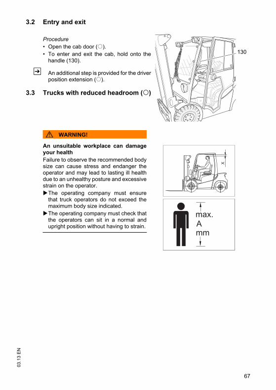
N3.2 Entry and exit
Procedure• Open the cab door (o).• To enter and exit the cab, hold onto the
handle (130).
Z An additional step is provided for the driverposition extension (o).
3.3 Trucks with reduced headroom (o)
WARNING!
An unsuitable workplace can damageyour healthFailure to observe the recommended bodysize can cause stress and endanger theoperator and may lead to lasting ill healthdue to an unhealthy posture and excessivestrain on the operator.
The operating company must ensurethat truck operators do not exceed themaximum body size indicated.The operating company must check thatthe operators can sit in a normal andupright position without having to strain.
130
o
03.1
3 E
N
68
3.4 Setting up the operator position
WARNING!
Accidents can occur if the driver's seat, steering column and armrest are notengagedThe driver's seat, steering column and armrest can accidentally adjust during traveland therefore cannot be operated safely.
Do not adjust the driver’s seat, steering column or armrest while travelling.
Procedure• Before starting to travel, adjust the driver’s seat, steering column and armrest (if
necessary) so that all the controls are within reach and can be applied withouthaving to strain.
• Adjust the visibility aid equipment (mirrors, camera systems etc.) so that the workingenvironment can be clearly seen.
3.4.1 Adjusting the driver’s seat
WARNING!
Risk of accidents and damage to health An incorrectly adjusted driver’s seat can result in accidents and damage to health.
Do not adjust the driver’s seat while travelling.The driver’s seat should lock in position after adjustment.Check and adjust the individual driver's seat setting before starting up the truck.Hold the weight setting lever only by the recess, do not reach through underneaththe lever.
69
03.1
3 E
N
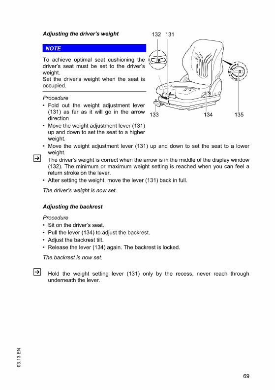
Adjusting the driver's weight
NOTE
To achieve optimal seat cushioning thedriver’s seat must be set to the driver’sweight. Set the driver's weight when the seat isoccupied.
Procedure• Fold out the weight adjustment lever
(131) as far as it will go in the arrowdirection
• Move the weight adjustment lever (131)up and down to set the seat to a higherweight.
• Move the weight adjustment lever (131) up and down to set the seat to a lowerweight.
Z The driver's weight is correct when the arrow is in the middle of the display window(132). The minimum or maximum weight setting is reached when you can feel areturn stroke on the lever.
• After setting the weight, move the lever (131) back in full.
The driver’s weight is now set.
Adjusting the backrest
Procedure• Sit on the driver’s seat.• Pull the lever (134) to adjust the backrest.• Adjust the backrest tilt.• Release the lever (134) again. The backrest is locked.
The backrest is now set.
Z Hold the weight setting lever (131) only by the recess, never reach throughunderneath the lever.
131
134133
132
135
03.1
3 E
N
70
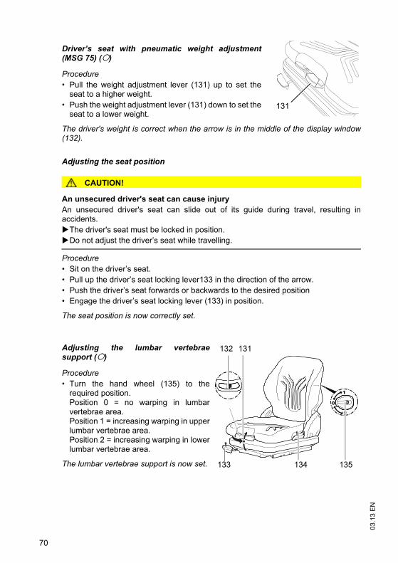
Driver’s seat with pneumatic weight adjustment(MSG 75) (o)
Procedure• Pull the weight adjustment lever (131) up to set the
seat to a higher weight.• Push the weight adjustment lever (131) down to set the
seat to a lower weight.
The driver's weight is correct when the arrow is in the middle of the display window(132).
Adjusting the seat position
CAUTION!
An unsecured driver's seat can cause injuryAn unsecured driver's seat can slide out of its guide during travel, resulting inaccidents.
The driver's seat must be locked in position.Do not adjust the driver’s seat while travelling.
Procedure• Sit on the driver’s seat.• Pull up the driver’s seat locking lever133 in the direction of the arrow.• Push the driver’s seat forwards or backwards to the desired position• Engage the driver’s seat locking lever (133) in position.
The seat position is now correctly set.
Adjusting the lumbar vertebraesupport (o)
Procedure• Turn the hand wheel (135) to the
required position.Position 0 = no warping in lumbarvertebrae area.Position 1 = increasing warping in upperlumbar vertebrae area.Position 2 = increasing warping in lowerlumbar vertebrae area.
The lumbar vertebrae support is now set.
131
131
134133
132
135
o
o
71
03.1
3 E
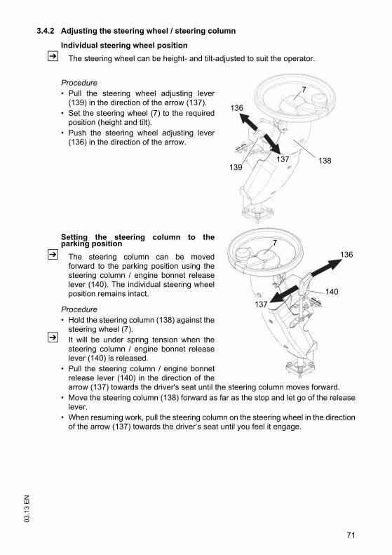
N3.4.2 Adjusting the steering wheel / steering column
Individual steering wheel positionZ The steering wheel can be height- and tilt-adjusted to suit the operator.
Procedure• Pull the steering wheel adjusting lever
(139) in the direction of the arrow (137).• Set the steering wheel (7) to the required
position (height and tilt).• Push the steering wheel adjusting lever
(136) in the direction of the arrow.
Setting the steering column to theparking position
Z The steering column can be movedforward to the parking position using thesteering column / engine bonnet releaselever (140). The individual steering wheelposition remains intact.
Procedure• Hold the steering column (138) against the
steering wheel (7).Z It will be under spring tension when the
steering column / engine bonnet releaselever (140) is released.
• Pull the steering column / engine bonnetrelease lever (140) in the direction of thearrow (137) towards the driver's seat until the steering column moves forward.
• Move the steering column (138) forward as far as the stop and let go of the releaselever.
• When resuming work, pull the steering column on the steering wheel in the directionof the arrow (137) towards the driver’s seat until you feel it engage.
136
137
7
138139
7136
140137
03.1
3 E
N
72
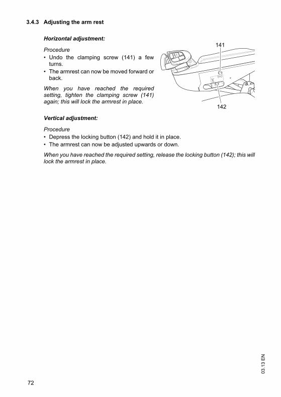
3.4.3 Adjusting the arm rest
Horizontal adjustment:
Procedure• Undo the clamping screw (141) a few
turns.• The armrest can now be moved forward or
back.
When you have reached the requiredsetting, tighten the clamping screw (141)again; this will lock the armrest in place.
Vertical adjustment:
Procedure• Depress the locking button (142) and hold it in place.• The armrest can now be adjusted upwards or down.
When you have reached the required setting, release the locking button (142); this willlock the armrest in place.
141
142
73
03.1
3 E
N3.5 Seat Belt
WARNING!
Travelling without a seat belt increases the risk of injury.Accidents or personal injury can result if the seat belt is not worn or is modified.
Always put the seat belt on before starting the industrial truck.Do not modify the seat belt.Damaged or non-operational seat belts must be replaced by trained personnel.Seat belts must always be replaced after an accident.Only original spare parts must be used for retrofits or repairs.Report any defects immediately to your supervisor.Remove the truck from service until a functional seat belt has been fitted.
Z Protect the seat belt from contamination (e.g. cover it when the truck is idle) andclean it regularly. Frozen belt locks or pulleys must be thawed out and dried toprevent them from freezing up again.The temperature of the warm air should not exceed +60 °C!
Starting the industrial truck on steep slopesThe automatic blocking system locks the belt in the retractor when the truck ispositioned on a steep slope. This prevents the belt from being pulled out of theretractor.
Z Carefully drive the truck off the slope and then put on the belt.
Checking the seat belt
Procedure• Check the attachment points for wear and damage.• Check the cover for damage.• Pull the belt out fully from the retractor and check for damage (loose seams, fraying
and nicks).• Test the belt buckle and make sure the belt returns correctly into the retractor.
Check the automatic locking system
Procedure• Park the truck on a level surface.• Jerk the seat belt out suddenly.
Z The locking system should prevent the belt from coming out.
The seat belt has now been checked.
03.1
3 E
N
74
4 Industrial Truck Operation
4.1 Safety regulations for truck operationTravel routes and work areasOnly use lanes and routes specifically designated for truck traffic. Unauthorised thirdparties must stay away from work areas. Loads must only be stored in places speciallydesignated for this purpose.The truck must only be operated in work areas with sufficient lighting to avoid dangerto personnel and materials. Additional equipment is necessary to operate the truck inareas of insufficient lighting.
DANGER!
Do not exceed the permissible surface and point loading on the travel lanes.At blind spots get a second person to assist.The driver must ensure that the loading dock /dock leveller cannot be removed orcome loose during loading/unloading.
NOTE
Loads must not be deposited on travel or escape routes, in front of safety mechanismsor operating equipment that must be accessible at all times.
Travel conductThe operator must adapt the travel speed to local conditions. The truck must be drivenat slow speed when negotiating bends or narrow passageways, when passingthrough swing doors and at blind spots. The operator must always observe anadequate braking distance between the forklift truck and the vehicle in front and mustbe in control of the truck at all times. Abrupt stopping (except in emergencies), rapidU turns and overtaking at dangerous or blind spots are not permitted. Do not lean outor reach beyond the working and operating area.
Do not use a mobile phone or walkie-talkie without a handsfree device while operatingthe truck.
Hazardous situationsIf the truck is about to tip over, do not loosen the seat belt. The operator must not jumpoff the truck. The operator must lean his upper body over the steering wheel and holdon with both hands. Tilt your body in the opposite direction of fall.
Travel visibilityThe operator must look in the direction of travel and must always have a clear view ofthe route ahead. If the truck is carrying loads that affect visibility, the truck must travelagainst the load direction. If this is not possible, a second person must walk alongsidethe truck as a lookout to observe the travel route while maintaining eye contact withthe operator. Proceed only at walking pace and with particular care. Stop the truck assoon as you lose eye contact.
75
03.1
3 E
N
Negotiating slopes and inclinesNegotiating slopes and inclines up to 15% is only permitted if they are specificallydesigned as travel routes, are clean and have a non-slip surface and providing theycan be safely travelled along in accordance with the truck's technical specifications.The truck must always be driven with the load facing uphill. The industrial truck mustnot be turned, operated at an angle or parked on inclines and slopes. Inclines mustonly be negotiated at slow speed, with the driver ready to brake at any moment.Particular care is required when travelling near slopes and quay walls.
Negotiating lifts, loading ramps and docksLifts may only be negotiated if they have sufficient capacity, are suitable for driving onand authorised for truck traffic by the owner. The driver must satisfy himself of theabove before entering these areas. The truck must enter lifts with the load in front andmust take up a position which does not allow it to come into contact with the walls ofthe lift shaft. Persons riding in the lift with the forklift truck must only enter the lift afterthe truck has come to a rest and must leave the lift before the truck. The driver mustensure that the loading ramp / dock cannot move or come loose during loading /unloading.
Type of loads to be carriedThe operator must make sure that the load is in a satisfactory condition. Loads mustalways be positioned safely and carefully. Use suitable precautions to prevent partsof the load from tipping or falling down. Prevent liquid loads from sloshing out.
Inflammable liquids (e.g. fused metal etc.) may only be transported with suitableauxiliary equipment. Contact the manufacturer's customer service department.
Z For safety instructions on the nature of loads to be carried with attachments,see"Lifting, transporting and depositing loads" on page 90.
Towing trailersThe truck may only be used occasionally to tow trailers, see "Towing trailers" onpage 108
DANGER!
Exhaust emissions can be fatalThe truck must only be operated in well ventilated areas. If the truck is operated inenclosed areas, this can lead to a build-up of harmful exhaust emissions, resultingin dizziness, tiredness and even death.The operator must comply with legal requirements, technical standards and healthand safety regulations when operating an IC motor powered lift truck in closedrooms.
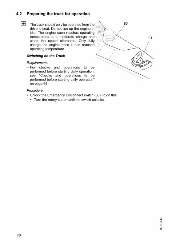
03.1
3 E
N
76
4.2 Preparing the truck for operation
Z The truck should only be operated from thedriver’s seat. Do not run up the engine inidle. The engine soon reaches operatingtemperature at a moderate charge andwhen the speed alternates. Only fullycharge the engine once it has reachedoperating temperature.
Switching on the Truck
Requirements– For checks and operations to be
performed before starting daily operation,see "Checks and operations to beperformed before starting daily operation"on page 65.
Procedure• Unlock the Emergency Disconnect switch (80), to do this
• Turn the rotary button until the switch unlocks.
80
81
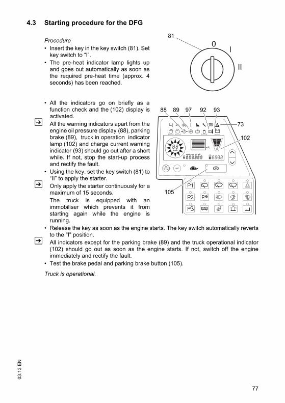
77
03.1
3 E
N4.3 Starting procedure for the DFG
Procedure• Insert the key in the key switch (81). Set
key switch to “I”.• The pre-heat indicator lamp lights up
and goes out automatically as soon asthe required pre-heat time (approx. 4seconds) has been reached.
•
• All the indicators go on briefly as afunction check and the (102) display isactivated.
Z All the warning indicators apart from theengine oil pressure display (88), parkingbrake (89), truck in operation indicatorlamp (102) and charge current warningindicator (93) should go out after a shortwhile. If not, stop the start-up processand rectify the fault.
• Using the key, set the key switch (81) to“II” to apply the starter.
Z Only apply the starter continuously for amaximum of 15 seconds. The truck is equipped with animmobiliser which prevents it fromstarting again while the engine isrunning.
• Release the key as soon as the engine starts. The key switch automatically revertsto the "I" position.
Z All indicators except for the parking brake (89) and the truck operational indicator(102) should go out as soon as the engine starts. If not, switch off the engineimmediately and rectify the fault.
• Test the brake pedal and parking brake button (105).
Truck is operational.
0I
II
81
km/h
R
73
9288 9389 97
102
105
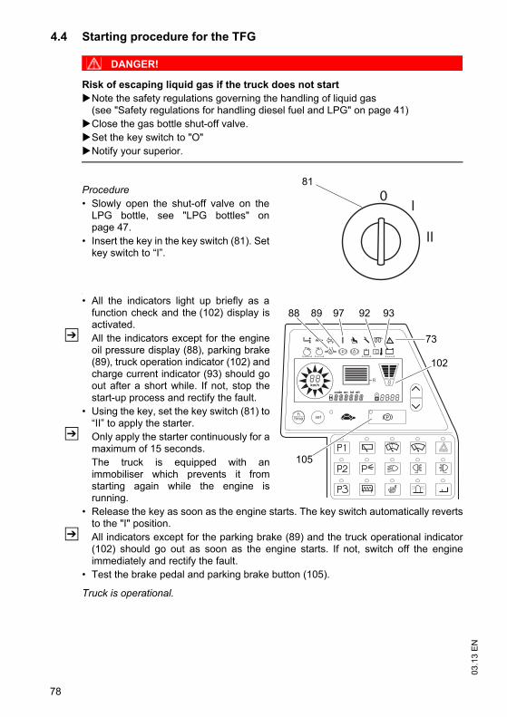
03.1
3 E
N
78
4.4 Starting procedure for the TFG
DANGER!
Risk of escaping liquid gas if the truck does not startNote the safety regulations governing the handling of liquid gas(see "Safety regulations for handling diesel fuel and LPG" on page 41)Close the gas bottle shut-off valve.Set the key switch to "O"Notify your superior.
Procedure• Slowly open the shut-off valve on the
LPG bottle, see "LPG bottles" onpage 47.
• Insert the key in the key switch (81). Setkey switch to “I”.
•
• All the indicators light up briefly as afunction check and the (102) display isactivated.
Z All the indicators except for the engineoil pressure display (88), parking brake(89), truck operation indicator (102) andcharge current indicator (93) should goout after a short while. If not, stop thestart-up process and rectify the fault.
• Using the key, set the key switch (81) to“II” to apply the starter.
Z Only apply the starter continuously for amaximum of 15 seconds. The truck is equipped with animmobiliser which prevents it fromstarting again while the engine isrunning.
• Release the key as soon as the engine starts. The key switch automatically revertsto the "I" position.
Z All indicators except for the parking brake (89) and the truck operational indicator(102) should go out as soon as the engine starts. If not, switch off the engineimmediately and rectify the fault.
• Test the brake pedal and parking brake button (105).
Truck is operational.
0I
II
81
km/h
R
73
9288 9389 97
102
105
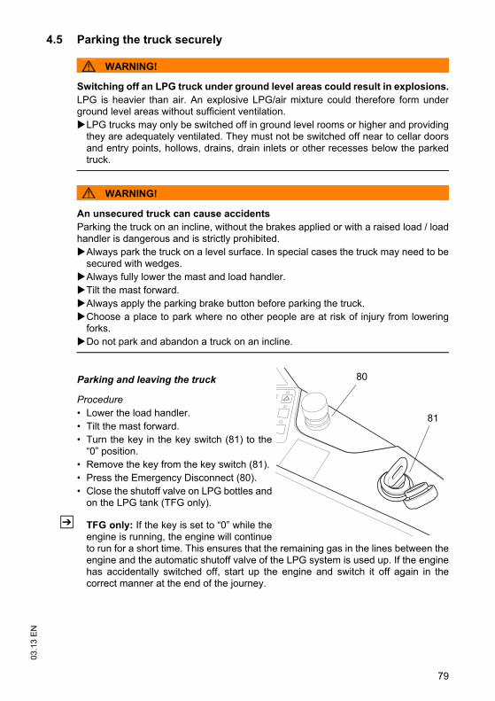
79
03.1
3 E
N4.5 Parking the truck securely
WARNING!
Switching off an LPG truck under ground level areas could result in explosions.LPG is heavier than air. An explosive LPG/air mixture could therefore form underground level areas without sufficient ventilation.
LPG trucks may only be switched off in ground level rooms or higher and providingthey are adequately ventilated. They must not be switched off near to cellar doorsand entry points, hollows, drains, drain inlets or other recesses below the parkedtruck.
WARNING!
An unsecured truck can cause accidentsParking the truck on an incline, without the brakes applied or with a raised load / loadhandler is dangerous and is strictly prohibited.
Always park the truck on a level surface. In special cases the truck may need to besecured with wedges.Always fully lower the mast and load handler.Tilt the mast forward.Always apply the parking brake button before parking the truck.Choose a place to park where no other people are at risk of injury from loweringforks. Do not park and abandon a truck on an incline.
Parking and leaving the truck
Procedure• Lower the load handler.• Tilt the mast forward.• Turn the key in the key switch (81) to the
“0” position.• Remove the key from the key switch (81).• Press the Emergency Disconnect (80).• Close the shutoff valve on LPG bottles and
on the LPG tank (TFG only).
Z TFG only: If the key is set to “0” while theengine is running, the engine will continueto run for a short time. This ensures that the remaining gas in the lines between theengine and the automatic shutoff valve of the LPG system is used up. If the enginehas accidentally switched off, start up the engine and switch it off again in thecorrect manner at the end of the journey.
80
81
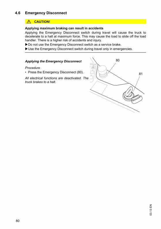
03.1
3 E
N
80
4.6 Emergency Disconnect
CAUTION!
Applying maximum braking can result in accidentsApplying the Emergency Disconnect switch during travel will cause the truck todecelerate to a halt at maximum force. This may cause the load to slide off the loadhandler. There is a higher risk of accidents and injury.
Do not use the Emergency Disconnect switch as a service brake.Use the Emergency Disconnect switch during travel only in emergencies.
Applying the Emergency Disconnect
Procedure• Press the Emergency Disconnect (80).
All electrical functions are deactivated. Thetruck brakes to a halt.
80
81
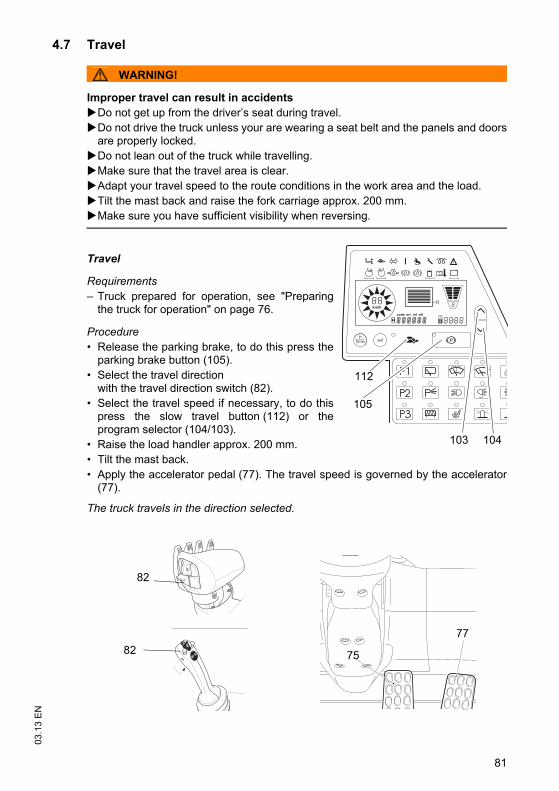
81
03.1
3 E
N4.7 Travel
WARNING!
Improper travel can result in accidents Do not get up from the driver’s seat during travel.Do not drive the truck unless your are wearing a seat belt and the panels and doorsare properly locked.Do not lean out of the truck while travelling.Make sure that the travel area is clear.Adapt your travel speed to the route conditions in the work area and the load.Tilt the mast back and raise the fork carriage approx. 200 mm.Make sure you have sufficient visibility when reversing.
Travel
Requirements– Truck prepared for operation, see "Preparing
the truck for operation" on page 76.
Procedure• Release the parking brake, to do this press the
parking brake button (105).• Select the travel direction
with the travel direction switch (82).• Select the travel speed if necessary, to do this
press the slow travel button (112) or theprogram selector (104/103).
• Raise the load handler approx. 200 mm.• Tilt the mast back.• Apply the accelerator pedal (77). The travel speed is governed by the accelerator
(77).
The truck travels in the direction selected.
km/h
R
105
104103
112
77
75
82
82
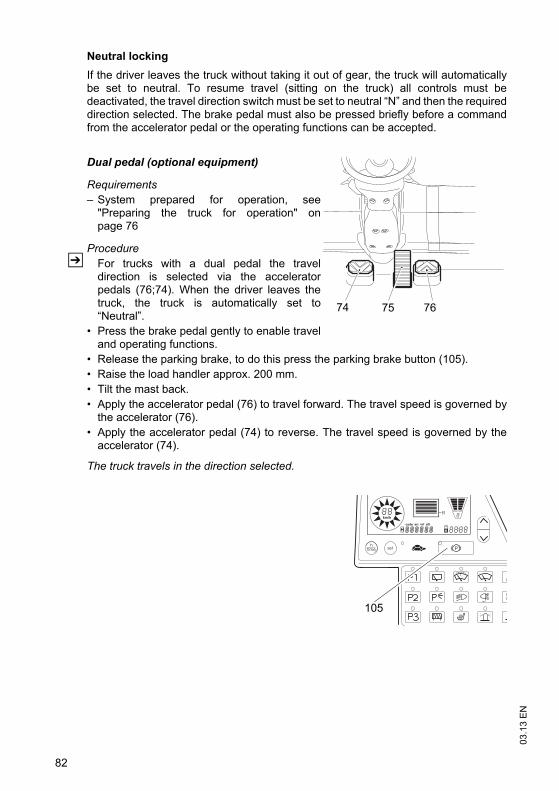
03.1
3 E
N
82
Neutral lockingIf the driver leaves the truck without taking it out of gear, the truck will automaticallybe set to neutral. To resume travel (sitting on the truck) all controls must bedeactivated, the travel direction switch must be set to neutral “N” and then the requireddirection selected. The brake pedal must also be pressed briefly before a commandfrom the accelerator pedal or the operating functions can be accepted.
Dual pedal (optional equipment)
Requirements– System prepared for operation, see
"Preparing the truck for operation" onpage 76
ProcedureZ For trucks with a dual pedal the travel
direction is selected via the acceleratorpedals (76;74). When the driver leaves thetruck, the truck is automatically set to“Neutral”.
• Press the brake pedal gently to enable traveland operating functions.
• Release the parking brake, to do this press the parking brake button (105).• Raise the load handler approx. 200 mm.• Tilt the mast back.• Apply the accelerator pedal (76) to travel forward. The travel speed is governed by
the accelerator (76).• Apply the accelerator pedal (74) to reverse. The travel speed is governed by the
accelerator (74).
The truck travels in the direction selected.
7674 75
km/h
R
105
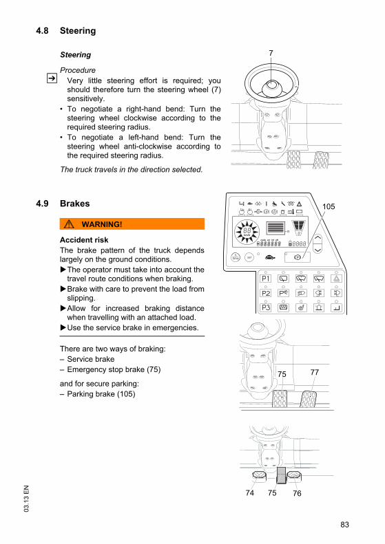
83
03.1
3 E
N4.8 Steering
Steering
ProcedureZ Very little steering effort is required; you
should therefore turn the steering wheel (7)sensitively.
• To negotiate a right-hand bend: Turn thesteering wheel clockwise according to therequired steering radius.
• To negotiate a left-hand bend: Turn thesteering wheel anti-clockwise according tothe required steering radius.
The truck travels in the direction selected.
4.9 Brakes
WARNING!
Accident riskThe brake pattern of the truck dependslargely on the ground conditions.
The operator must take into account thetravel route conditions when braking.Brake with care to prevent the load fromslipping.Allow for increased braking distancewhen travelling with an attached load.Use the service brake in emergencies.
There are two ways of braking:– Service brake– Emergency stop brake (75)
and for secure parking:– Parking brake (105)
7
75
7574 76
77
km/h
R
105
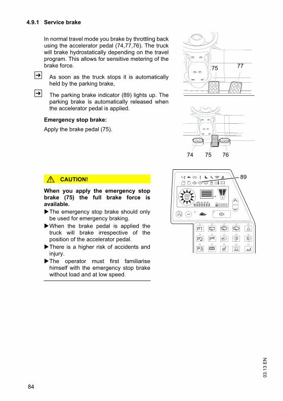
03.1
3 E
N
84
4.9.1 Service brake
In normal travel mode you brake by throttling backusing the accelerator pedal (74,77,76). The truckwill brake hydrostatically depending on the travelprogram. This allows for sensitive metering of thebrake force.
Z As soon as the truck stops it is automaticallyheld by the parking brake,
Z The parking brake indicator (89) lights up. Theparking brake is automatically released whenthe accelerator pedal is applied.
Emergency stop brake: Apply the brake pedal (75).
CAUTION!
When you apply the emergency stopbrake (75) the full brake force isavailable.
The emergency stop brake should onlybe used for emergency braking.When the brake pedal is applied thetruck will brake irrespective of theposition of the accelerator pedal. There is a higher risk of accidents andinjury. The operator must first familiarisehimself with the emergency stop brakewithout load and at low speed.
7775
767574
km/h
R
89
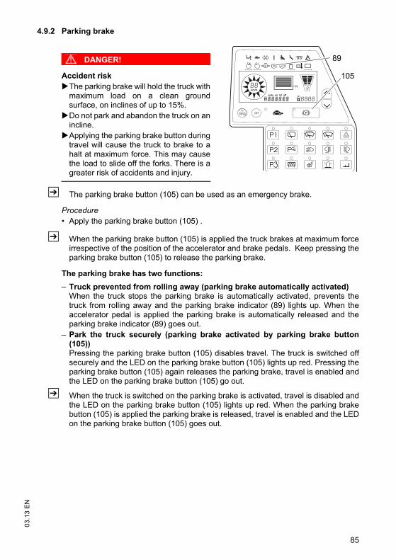
85
03.1
3 E
N4.9.2 Parking brake
DANGER!
Accident riskThe parking brake will hold the truck withmaximum load on a clean groundsurface, on inclines of up to 15%.Do not park and abandon the truck on anincline.Applying the parking brake button duringtravel will cause the truck to brake to ahalt at maximum force. This may causethe load to slide off the forks. There is agreater risk of accidents and injury.
Z The parking brake button (105) can be used as an emergency brake.
Procedure• Apply the parking brake button (105) .
Z When the parking brake button (105) is applied the truck brakes at maximum forceirrespective of the position of the accelerator and brake pedals. Keep pressing theparking brake button (105) to release the parking brake.
The parking brake has two functions:– Truck prevented from rolling away (parking brake automatically activated)
When the truck stops the parking brake is automatically activated, prevents thetruck from rolling away and the parking brake indicator (89) lights up. When theaccelerator pedal is applied the parking brake is automatically released and theparking brake indicator (89) goes out.
– Park the truck securely (parking brake activated by parking brake button(105))Pressing the parking brake button (105) disables travel. The truck is switched offsecurely and the LED on the parking brake button (105) lights up red. Pressing theparking brake button (105) again releases the parking brake, travel is enabled andthe LED on the parking brake button (105) go out.
Z When the truck is switched on the parking brake is activated, travel is disabled andthe LED on the parking brake button (105) lights up red. When the parking brakebutton (105) is applied the parking brake is released, travel is enabled and the LEDon the parking brake button (105) goes out.
km/h
R
105
89
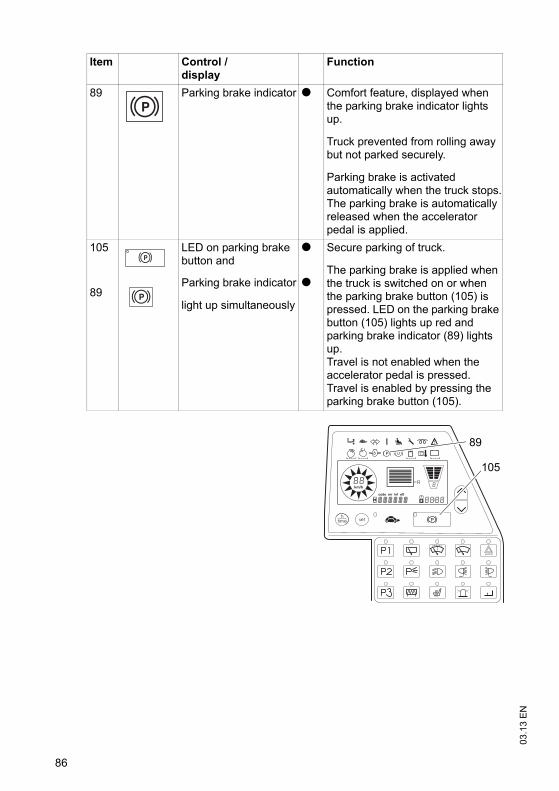
03.1
3 E
N
86
Item Control /display
Function
89 Parking brake indicator t Comfort feature, displayed when the parking brake indicator lights up.
Truck prevented from rolling away but not parked securely.
Parking brake is activated automatically when the truck stops.The parking brake is automatically released when the accelerator pedal is applied.
105
89
LED on parking brake button and
t Secure parking of truck.
The parking brake is applied when the truck is switched on or when the parking brake button (105) is pressed. LED on the parking brake button (105) lights up red and parking brake indicator (89) lights up.Travel is not enabled when the accelerator pedal is pressed.Travel is enabled by pressing the parking brake button (105).
Parking brake indicator
light up simultaneously
t
km/h
R
105
89
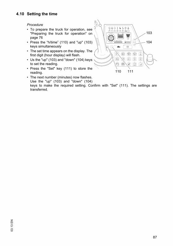
87
03.1
3 E
N4.10 Setting the time
Procedure• To prepare the truck for operation, see
"Preparing the truck for operation" onpage 76
• Press the “h/time” (110) and "up" (103)keys simultaneously
• The set time appears on the display. Thefirst digit (hour display) will flash.
• Us the "up" (103) and "down" (104) keysto set the reading.
• Press the "Set" key (111) to store thereading.
• The next number (minutes) now flashes.Use the "up" (103) and "down" (104)keys to make the required setting. Confirm with "Set" (111). The settings aretransferred.
km/h
103
110 111
104
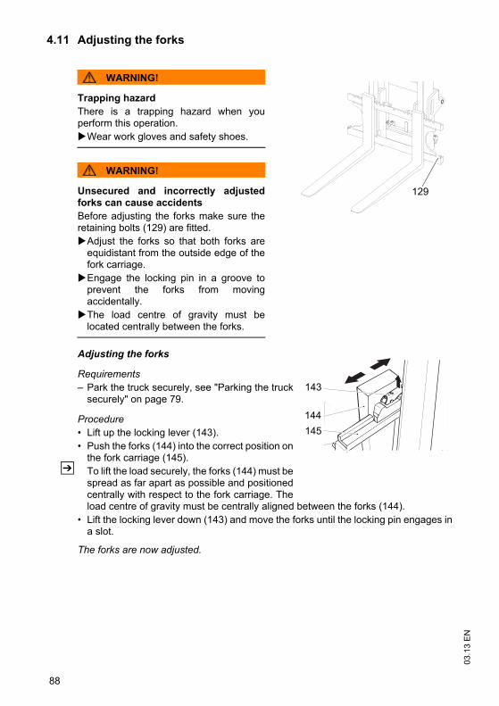
03.1
3 E
N
88
4.11 Adjusting the forks
WARNING!
Trapping hazardThere is a trapping hazard when youperform this operation.
Wear work gloves and safety shoes.
WARNING!
Unsecured and incorrectly adjustedforks can cause accidents Before adjusting the forks make sure theretaining bolts (129) are fitted.
Adjust the forks so that both forks areequidistant from the outside edge of thefork carriage.Engage the locking pin in a groove toprevent the forks from movingaccidentally.The load centre of gravity must belocated centrally between the forks.
Adjusting the forks
Requirements– Park the truck securely, see "Parking the truck
securely" on page 79.
Procedure• Lift up the locking lever (143).• Push the forks (144) into the correct position on
the fork carriage (145).Z To lift the load securely, the forks (144) must be
spread as far apart as possible and positionedcentrally with respect to the fork carriage. Theload centre of gravity must be centrally aligned between the forks (144).
• Lift the locking lever down (143) and move the forks until the locking pin engages ina slot.
The forks are now adjusted.
129
143
144145
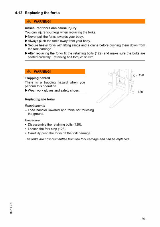
89
03.1
3 E
N4.12 Replacing the forks
WARNING!
Unsecured forks can cause injuryYou can injure your legs when replacing the forks.
Never pull the forks towards your body.Always push the forks away from your body.Secure heavy forks with lifting slings and a crane before pushing them down fromthe fork carriage.After replacing the forks fit the retaining bolts (129) and make sure the bolts areseated correctly. Retaining bolt torque: 85 Nm.
WARNING!
Trapping hazardThere is a trapping hazard when youperform this operation.
Wear work gloves and safety shoes.
Replacing the forks
Requirements– Load handler lowered and forks not touching
the ground.
Procedure• Disassemble the retaining bolts (129).• Loosen the fork stop (128).• Carefully push the forks off the fork carriage.
The forks are now dismantled from the fork carriage and can be replaced.
129
128
03.1
3 E
N
90
4.13 Lifting, transporting and depositing loads
WARNING!
Unsecured and incorrectly positioned loads can cause accidents. Before lifting a load the operator must make sure that it has been correctly palletisedand does not exceed the truck’s capacity.
Instruct other people to move out of the hazardous area of the truck. Stop workingwith the truck if people do not leave the hazardous area.Only carry loads that have been correctly secured and positioned. Use suitableprecautions to prevent parts of the load from tipping or falling down.Do not transport loads other than on the authorised load handler.Damaged loads must not be transported.If the stacked load obscures forward visibility, then you must reverse the truck.Do not exceed the maximum loads specified on the capacity plate.Check the fork spread before lifting the load and adjust if necessary.Insert the forks as far as possible underneath the load.
Lifting loads
Requirements– Load correctly palletised.– Fork spread for the pallet checked and adjusted if necessary.– Load weight matches the truck's capacity.– Forks evenly loaded for heavy loads.
Procedure• Drive the truck carefully up to the pallet.• Set the mast vertical.• Slowly insert the forks into the pallet until the fork shank touches the pallet.• Raise the load handler. • Reverse carefully and slowly until the load is outside the storage area. Make sure
you have enough clear space to reverse into.
91
03.1
3 E
N
NOTE
Loads must not be deposited on travel or escape routes, in front of safety mechanismsor operating equipment that must be accessible at all times.
Transporting loads
Requirements– Load raised correctly.– Load handler lowered for transport (approx. 150 - 200 mm above the ground).– Mast tilted back fully.
Procedure• Accelerate and decelerate sensitively.• Adapt your travel speed to the conditions of the route and the load you are
transporting.• Watch out for other traffic at crossings and passageways. • Always travel with a lookout at blind spots.• On slopes and inclines always carry the load facing uphill, never approach at an
angle or turn.
Depositing loads
Requirements– Storage location suitable for storing the load.
Procedure• Set the mast vertical.• Drive the truck carefully up to the storage location.• Carefully lower the load handler so that the forks are clear of the load.
Z Avoid depositing the load to prevent damage to the load and the load handler.• Lowers the load handler.• Carefully remove the forks from the pallet.
The load is deposited.
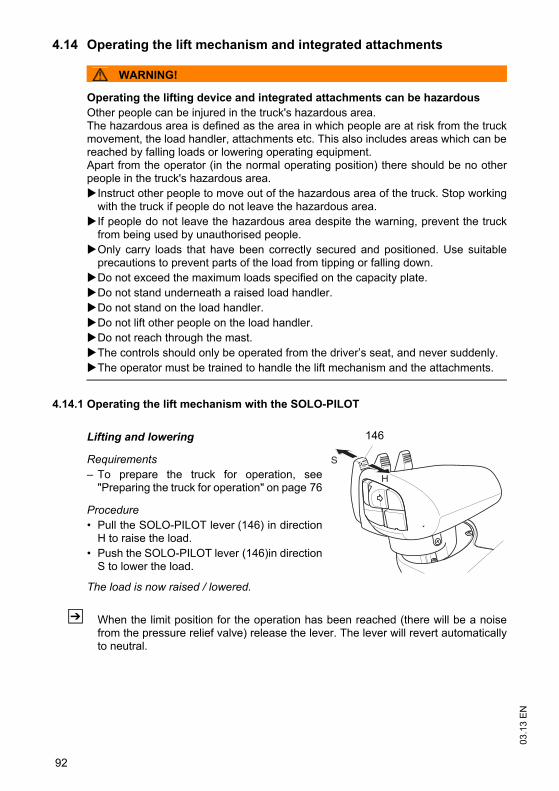
03.1
3 E
N
92
4.14 Operating the lift mechanism and integrated attachments
WARNING!
Operating the lifting device and integrated attachments can be hazardous Other people can be injured in the truck's hazardous area.The hazardous area is defined as the area in which people are at risk from the truckmovement, the load handler, attachments etc. This also includes areas which can bereached by falling loads or lowering operating equipment.Apart from the operator (in the normal operating position) there should be no otherpeople in the truck's hazardous area.
Instruct other people to move out of the hazardous area of the truck. Stop workingwith the truck if people do not leave the hazardous area.If people do not leave the hazardous area despite the warning, prevent the truckfrom being used by unauthorised people.Only carry loads that have been correctly secured and positioned. Use suitableprecautions to prevent parts of the load from tipping or falling down.Do not exceed the maximum loads specified on the capacity plate.Do not stand underneath a raised load handler.Do not stand on the load handler.Do not lift other people on the load handler.Do not reach through the mast.The controls should only be operated from the driver’s seat, and never suddenly. The operator must be trained to handle the lift mechanism and the attachments.
4.14.1 Operating the lift mechanism with the SOLO-PILOT
Lifting and lowering
Requirements– To prepare the truck for operation, see
"Preparing the truck for operation" on page 76
Procedure• Pull the SOLO-PILOT lever (146) in direction
H to raise the load.• Push the SOLO-PILOT lever (146)in direction
S to lower the load.
The load is now raised / lowered.
Z When the limit position for the operation has been reached (there will be a noisefrom the pressure relief valve) release the lever. The lever will revert automaticallyto neutral.
S
H
146
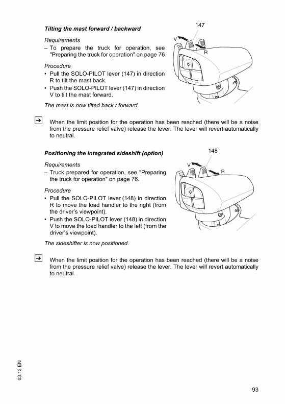
93
03.1
3 E
N
Tilting the mast forward / backward
Requirements– To prepare the truck for operation, see
"Preparing the truck for operation" on page 76
Procedure• Pull the SOLO-PILOT lever (147) in direction
R to tilt the mast back.• Push the SOLO-PILOT lever (147) in direction
V to tilt the mast forward.
The mast is now tilted back / forward.
Z When the limit position for the operation has been reached (there will be a noisefrom the pressure relief valve) release the lever. The lever will revert automaticallyto neutral.
Positioning the integrated sideshift (option)
Requirements– Truck prepared for operation, see "Preparing
the truck for operation" on page 76.
Procedure• Pull the SOLO-PILOT lever (148) in direction
R to move the load handler to the right (fromthe driver’s viewpoint).
• Push the SOLO-PILOT lever (148) in directionV to move the load handler to the left (from thedriver’s viewpoint).
The sideshifter is now positioned.
Z When the limit position for the operation has been reached (there will be a noisefrom the pressure relief valve) release the lever. The lever will revert automaticallyto neutral.
R
V
147
RV
148
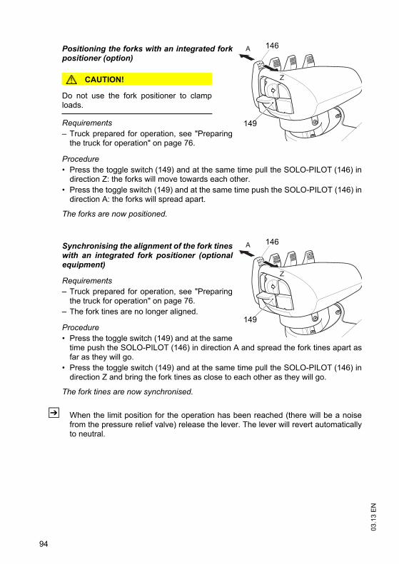
03.1
3 E
N
94
Positioning the forks with an integrated forkpositioner (option)
CAUTION!
Do not use the fork positioner to clamploads.
Requirements– Truck prepared for operation, see "Preparing
the truck for operation" on page 76.
Procedure• Press the toggle switch (149) and at the same time pull the SOLO-PILOT (146) in
direction Z: the forks will move towards each other.• Press the toggle switch (149) and at the same time push the SOLO-PILOT (146) in
direction A: the forks will spread apart.
The forks are now positioned.
Synchronising the alignment of the fork tineswith an integrated fork positioner (optionalequipment)
Requirements– Truck prepared for operation, see "Preparing
the truck for operation" on page 76. – The fork tines are no longer aligned.
Procedure• Press the toggle switch (149) and at the same
time push the SOLO-PILOT (146) in direction A and spread the fork tines apart asfar as they will go.
• Press the toggle switch (149) and at the same time pull the SOLO-PILOT (146) indirection Z and bring the fork tines as close to each other as they will go.
The fork tines are now synchronised.
Z When the limit position for the operation has been reached (there will be a noisefrom the pressure relief valve) release the lever. The lever will revert automaticallyto neutral.
A
Z
149
146
A
Z
149
146
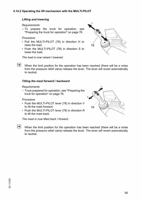
95
03.1
3 E
N4.14.2 Operating the lift mechanism with the MULTI-PILOT
Lifting and lowering
Requirements– To prepare the truck for operation, see
"Preparing the truck for operation" on page 76
Procedure• Pull the MULTI-PILOT (78) in direction H to
raise the load.• Push the MULTI-PILOT (78) in direction S to
lower the load.
The load is now raised / lowered.
Z When the limit position for the operation has been reached (there will be a noisefrom the pressure relief valve) release the lever. The lever will revert automaticallyto neutral.
Tilting the mast forward / backward
Requirements– Truck prepared for operation, see "Preparing the
truck for operation" on page 76.
Procedure• Push the MULTI-PILOT lever (78) in direction V
to tilt the mast forward.• Push the MULTI-PILOT lever (78) in direction R
to tilt the mast back.
The mast is now tilted back / forward.
Z When the limit position for the operation has been reached (there will be a noisefrom the pressure relief valve) release the lever. The lever will revert automaticallyto neutral.
HH
S
78
V
R
78
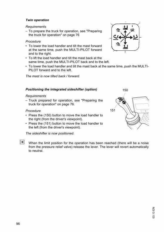
03.1
3 E
N
96
Twin operation
Requirements– To prepare the truck for operation, see "Preparing
the truck for operation" on page 76
Procedure• To lower the load handler and tilt the mast forward
at the same time, push the MULTI-PILOT forwardand to the right.
• To lift the load handler and tilt the mast back at thesame time, push the MULTI-PILOT back and to the left.
• To lower the load handler and tilt the mast back at the same time, push the MULTI-PILOT forward and to the left.
The mast is now tilted back / forward.
Positioning the integrated sideshifter (option)
Requirements– Truck prepared for operation, see "Preparing the
truck for operation" on page 76.
Procedure• Press the (150) button to move the load handler to
the right (from the driver's viewpoint).• Press the (151) button to move the load handler to
the left (from the driver's viewpoint).
The sideshifter is now positioned.
Z When the limit position for the operation has been reached (there will be a noisefrom the pressure relief valve) release the lever. The lever will revert automaticallyto neutral.
150
151
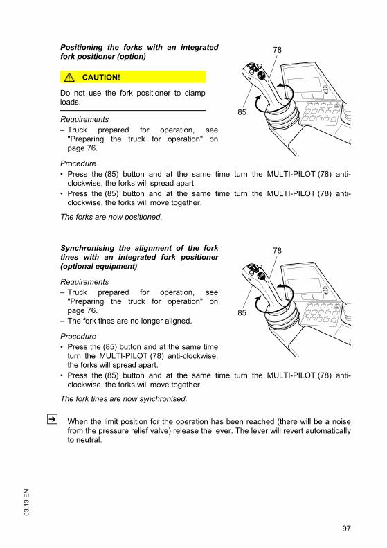
97
03.1
3 E
N
Positioning the forks with an integratedfork positioner (option)
CAUTION!
Do not use the fork positioner to clamploads.
Requirements– Truck prepared for operation, see
"Preparing the truck for operation" onpage 76.
Procedure• Press the (85) button and at the same time turn the MULTI-PILOT (78) anti-
clockwise, the forks will spread apart.• Press the (85) button and at the same time turn the MULTI-PILOT (78) anti-
clockwise, the forks will move together.
The forks are now positioned.
Synchronising the alignment of the forktines with an integrated fork positioner(optional equipment)
Requirements– Truck prepared for operation, see
"Preparing the truck for operation" onpage 76.
– The fork tines are no longer aligned.
Procedure• Press the (85) button and at the same time
turn the MULTI-PILOT (78) anti-clockwise,the forks will spread apart.
• Press the (85) button and at the same time turn the MULTI-PILOT (78) anti-clockwise, the forks will move together.
The fork tines are now synchronised.
Z When the limit position for the operation has been reached (there will be a noisefrom the pressure relief valve) release the lever. The lever will revert automaticallyto neutral.
85
78
85
78
03.1
3 E
N
98
4.15 Safety instructions for operating additional attachmentsZ Optionally, trucks can be fitted with one or more auxiliary hydraulic functions to
operate attachments. The auxiliary hydraulics are indicated with ZH1 and ZH2.Auxiliary hydraulic functions for exchangeable equipment are fitted withreplacement couplings on the fork carriage. To fit exchangeable equipment see"Fitting additional attachments" on page 105.
DANGER!
Attaching exchangeable equipment can result in accidents.Other people can be damaged by attaching exchangeable equipment. Use onlyexchangeable equipment which has been deemed safe after a risk analysis carriedout by the owner.
Only use attachments with a CE mark.Only use attachments that have been designed by the attachment manufacturer foruse with the respective industrial truck. Only use attachments that have been fitted for the purpose by the owner.Make sure the operator has been instructed in the use of the attachment and thathe uses it for its correct purpose. Re-assess the residual capacity of the truck and if it has been altered, attach anadditional capacity plate to the truck.Note the attachment manufacturer’s operating instructions.Only use attachments that do not restrict visibility in the travel direction.
Z If visibility in the travel direction is impaired, the operating company must determineand apply suitable measures to ensure the safe operation of the truck. A lookoutmay have to be used or certain hazardous areas may have to be cordoned off. Thetruck can also be equipped with optional visual aids such as a camera system ormirrors. Travelling with visual aids requires plenty of practice at slow speed.
99
03.1
3 E
N
Safety instructions for sideshifter and fork positioner attachments
WARNING!
Restricted visibility and reduced tilt resistance can cause accidentsWhen using sideshifters and fork positioners, the change in centre of gravity can resultin reduced lateral tilt resistance and accidents. Note that this affects visibility as well.
Adapt the travel speeds to the visibility and load.Make sure you have sufficient visibility when reversing.
Safety instructions for clamping attachments (e.g. baling clamps, barrelclamps, grabs etc.)
WARNING!
Falling loads can cause accidentsThis can result in malfunctions and the load can fall accidentally.
Clamping attachments may only be added to trucks which have a button to enableadditional hydraulic functions.Clamping attachments must only be operated on trucks will auxiliary hydraulics ZH1or ZH2.When connecting the attachment make sure that the hydraulic lines of theattachment are connected to the right ports, see "Fitting additional attachments" onpage 105.
Safety instructions for rotary attachments
WARNING!
A non-centred load centre of gravity can result in accidentsWhen using rotary devices and non-centred loads, the centre of gravity can bedisplaced from the centre with a high risk of accidents.
Adapt the travel speed to the load.Lift the load from the centre.
Safety instructions for telescopic attachments
WARNING!
Accident risk from increased tipover hazard and reduced residual capacity There is a greater risk of tipover with extended telescopic attachments.
Do not exceed the maximum loads specified on the capacity plate.Only use the telescopic function for stacking and retrieving.Retract the telescopic attachment fully during transport. Adapt the travel speed to changed load centre of gravity.
03.1
3 E
N
100
Safety instructions for attachments when transporting suspended loads
WARNING!
Swinging loads and a reduced residual capacity can result in accidents.Transporting hanging loads can reduce the stability of the truck.
Adapt the travel speed to the load, less than walking pace.Secure swinging loads for example with lifting slings.Reduce the residual capacity and have it certified by a expert.If the truck is to be operated with hanging loads, proof of sufficient safety distanceunder local operating conditions must be obtained from a specialist assessor.
Safety instructions for using loading buckets as attachments
WARNING!
Increased mast loading can cause accidents.When carrying out the daily checks and operations before starting, see "Checks andoperations to be performed before starting daily operation" on page 65, check inparticular check the fork carriage, mast rails and mast rollers for damage.
Fork extension safety instructions
WARNING!
Unsecured and oversized fork extensions can cause accidents.For fork extensions with an open cross sectional area, carry only loads that areresting along the entire length of the fork extension. Use only fork extensions with the same fork cross section and minimum fork lengthof the truck and which comply with the details on the fork extension data plate. The basic fork length must be at least 60% of the length of the fork extension.Lock the fork extensions onto the basic forks.When carrying out the daily checks and operations before starting, see "Checks andoperations to be performed before starting daily operation" on page 65, check alsothe fork extension lock.Mark any fork extensions with an incomplete or faulty lock and take them out ofservice.Do not use trucks with an incomplete or faulty fork extension lock. Replace the forkextension.Only restore the fork extension to service when the fault has been rectified.Use only fork extensions which are free of dirt and foreign bodies near the entryopening point. Clean the fork extensions as required.
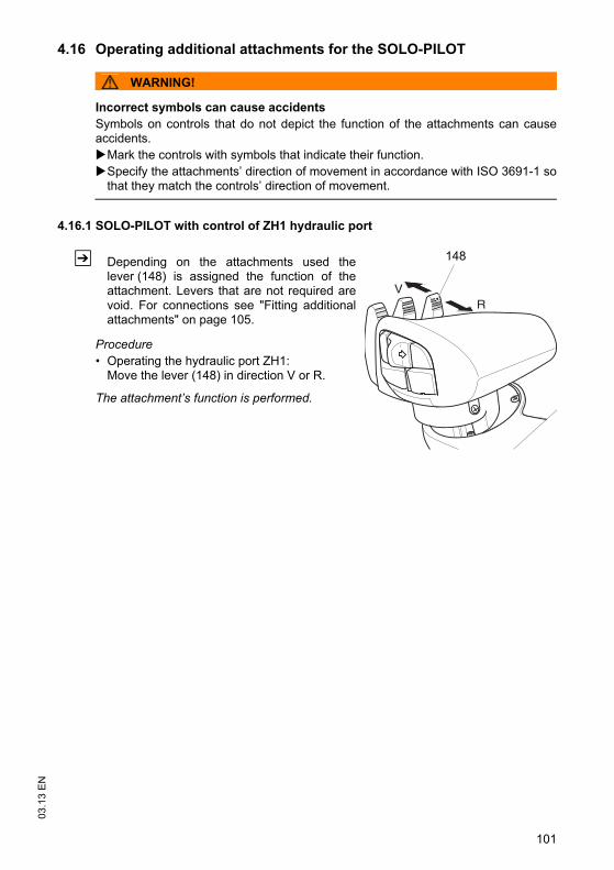
101
03.1
3 E
N4.16 Operating additional attachments for the SOLO-PILOT
WARNING!
Incorrect symbols can cause accidentsSymbols on controls that do not depict the function of the attachments can causeaccidents.
Mark the controls with symbols that indicate their function.Specify the attachments’ direction of movement in accordance with ISO 3691-1 sothat they match the controls’ direction of movement.
4.16.1 SOLO-PILOT with control of ZH1 hydraulic port
Z Depending on the attachments used thelever (148) is assigned the function of theattachment. Levers that are not required arevoid. For connections see "Fitting additionalattachments" on page 105.
Procedure• Operating the hydraulic port ZH1:
Move the lever (148) in direction V or R.
The attachment’s function is performed.
RV
148
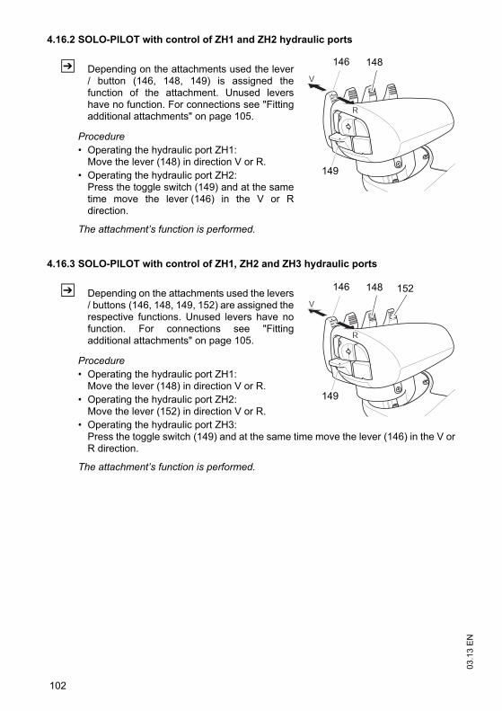
03.1
3 E
N
102
4.16.2 SOLO-PILOT with control of ZH1 and ZH2 hydraulic ports
Z Depending on the attachments used the lever/ button (146, 148, 149) is assigned thefunction of the attachment. Unused levershave no function. For connections see "Fittingadditional attachments" on page 105.
Procedure• Operating the hydraulic port ZH1:
Move the lever (148) in direction V or R. • Operating the hydraulic port ZH2:
Press the toggle switch (149) and at the sametime move the lever (146) in the V or Rdirection.
The attachment’s function is performed.
4.16.3 SOLO-PILOT with control of ZH1, ZH2 and ZH3 hydraulic ports
Z Depending on the attachments used the levers/ buttons (146, 148, 149, 152) are assigned therespective functions. Unused levers have nofunction. For connections see "Fittingadditional attachments" on page 105.
Procedure• Operating the hydraulic port ZH1:
Move the lever (148) in direction V or R.• Operating the hydraulic port ZH2:
Move the lever (152) in direction V or R.• Operating the hydraulic port ZH3:
Press the toggle switch (149) and at the same time move the lever (146) in the V orR direction.
The attachment’s function is performed.
R
V
146
149
148
R
V
146
149
152148
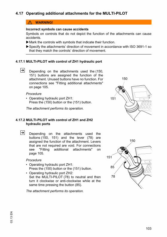
103
03.1
3 E
N4.17 Operating additional attachments for the MULTI-PILOT
WARNING!
Incorrect symbols can cause accidentsSymbols on controls that do not depict the function of the attachments can causeaccidents.
Mark the controls with symbols that indicate their function.Specify the attachments’ direction of movement in accordance with ISO 3691-1 sothat they match the controls’ direction of movement.
4.17.1 MULTI-PILOT with control of ZH1 hydraulic port
Z Depending on the attachments used the (150,151) buttons are assigned the function of theattachment. Unused buttons have no function. Forconnections see "Fitting additional attachments"on page 105.
Procedure• Operating hydraulic port ZH1:
Press the (150) button or the (151) button.
The attachment performs its operation.
4.17.2 MULTI-PILOT with control of ZH1 and ZH2 hydraulic ports
Z Depending on the attachments used thebuttons (150, 151) and the lever (78) areassigned the function of the attachment. Leversthat are not required are void. For connectionssee "Fitting additional attachments" onpage 105.
Procedure• Operating hydraulic port ZH1:
Press the (150) button or the (151) button.• Operating hydraulic port ZH2:
Set the MULTI-PILOT (78) to neutral and thenturn it clockwise or anti-clockwise while at thesame time pressing the button (85).
The attachment performs its operation.
150
151
150
151
78
85
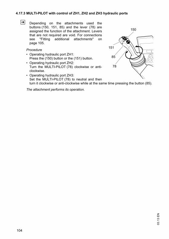
03.1
3 E
N
104
4.17.3 MULTI-PILOT with control of ZH1, ZH2 and ZH3 hydraulic ports
Z Depending on the attachments used thebuttons (150, 151, 85) and the lever (78) areassigned the function of the attachment. Leversthat are not required are void. For connectionssee "Fitting additional attachments" onpage 105.
Procedure• Operating hydraulic port ZH1:
Press the (150) button or the (151) button.• Operating hydraulic port ZH2:
Turn the MULTI-PILOT (78) clockwise or anti-clockwise.
• Operating hydraulic port ZH3:Set the MULTI-PILOT (78) to neutral and thenturn it clockwise or anti-clockwise while at the same time pressing the button (85).
The attachment performs its operation.
150
151
78
85
105
03.1
3 E
N4.18 Fitting additional attachments
WARNING!
Incorrectly connected attachments can cause accidents.Attachments with incorrectly connected hydraulic attachments can result in accidents.
Attachments must only be assembled and commissioned by trained, specialistpersonnel. Observe the manufacturer’s operating instructions.Before starting, check the fasteners are positioned correctly and securely and makesure they are complete. Before starting, make sure the attachment is working correctly.
Connect attachment hydraulically
Requirements– Hydraulic replacement coupling depressurised. – The exchange ports on the truck are marked ZH1 and ZH2.– Attachment directions of movement defined to match the controls’ direction of
movement.
Procedure• Depressurise the hydraulic replacement coupling.• Attach the plug connector and engage it in position. • Mark the controls with symbols that indicate their function.
The attachment is now hydraulically connected.
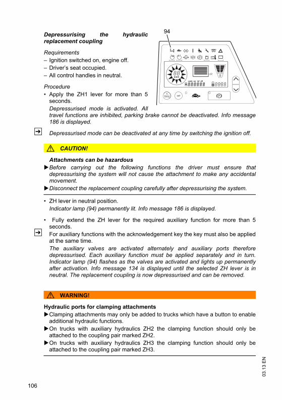
03.1
3 E
N
106
Depressurising the hydraulicreplacement coupling
Requirements– Ignition switched on, engine off.– Driver’s seat occupied.– All control handles in neutral.
Procedure• Apply the ZH1 lever for more than 5
seconds.Depressurised mode is activated. Alltravel functions are inhibited, parking brake cannot be deactivated. Info message186 is displayed.
Z Depressurised mode can be deactivated at any time by switching the ignition off.
CAUTION!
Attachments can be hazardousBefore carrying out the following functions the driver must ensure thatdepressurising the system will not cause the attachment to make any accidentalmovement. Disconnect the replacement coupling carefully after depressurising the system.
• ZH lever in neutral position. Indicator lamp (94) permanently lit. Info message 186 is displayed.
• Fully extend the ZH lever for the required auxiliary function for more than 5seconds.
Z For auxiliary functions with the acknowledgement key the key must also be appliedat the same time.The auxiliary valves are activated alternately and auxiliary ports thereforedepressurised. Each auxiliary function must be applied separately and in turn.Indicator lamp (94) flashes as the valves are activated and lights up permanentlyafter activation. Info message 134 is displayed until the selected ZH lever is inneutral. The replacement coupling is now depressurised and can be removed.
WARNING!
Hydraulic ports for clamping attachmentsClamping attachments may only be added to trucks which have a button to enableadditional hydraulic functions.On trucks with auxiliary hydraulics ZH2 the clamping function should only beattached to the coupling pair marked ZH2.On trucks with auxiliary hydraulics ZH3 the clamping function should only beattached to the coupling pair marked ZH3.
km/h
R
94
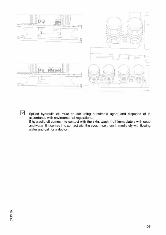
107
03.1
3 E
N
Z Spilled hydraulic oil must be set using a suitable agent and disposed of inaccordance with environmental regulations.If hydraulic oil comes into contact with the skin, wash it off immediately with soapand water. If it comes into contact with the eyes rinse them immediately with flowingwater and call for a doctor.
03.1
3 E
N
108
5 Towing trailers
DANGER!
Inappropriate speeds and excessive trailer loads can be dangerousIf you do not adapt your speed and / or use an excessive trailer load, the truck can pullapart when cornering and braking.
The truck should only be used occasionally to tow trailers. The overall weight of the trailer should not exceed the capacity indicated on thecapacity plate, see "Identification points and data plates" on page 30. If a load isalso transported on the load handler, the trailer load must be reduced by the sameamount.Do not exceed the maximum speed of 5 km/h km/h.A truck must not be continually operated with trailers.Do not use supporting loads.Towing must only be performed on level, secure travel routes.The owner must test trailer operation with the permissible tow load by means of atrial run under the applicable operating conditions on site.
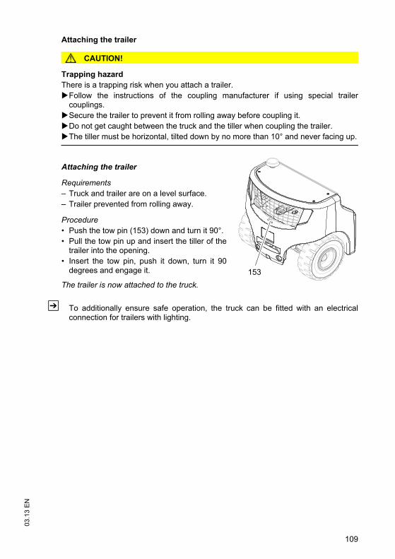
109
03.1
3 E
N
Attaching the trailer
CAUTION!
Trapping hazardThere is a trapping risk when you attach a trailer.
Follow the instructions of the coupling manufacturer if using special trailercouplings.Secure the trailer to prevent it from rolling away before coupling it.Do not get caught between the truck and the tiller when coupling the trailer.The tiller must be horizontal, tilted down by no more than 10° and never facing up.
Attaching the trailer
Requirements– Truck and trailer are on a level surface.– Trailer prevented from rolling away.
Procedure• Push the tow pin (153) down and turn it 90°.• Pull the tow pin up and insert the tiller of the
trailer into the opening.• Insert the tow pin, push it down, turn it 90
degrees and engage it.
The trailer is now attached to the truck.
Z To additionally ensure safe operation, the truck can be fitted with an electricalconnection for trailers with lighting.
153

03.1
3 E
N
110
6 Optional equipment
6.1 Keypad (CanCode) (o)
6.1.1 Code lock
The code lock allows a user or group of users to assign an individual user code. Travelprograms can also be assigned to the individual user codes. The user code isconfigured with a master code and is described in the following sections in thischapter.
When you have entered the valid user code the truck will be operational. The truck willbe able to perform travel, steering and hydraulic operations.
When you have entered the valid master code the truck will be switched on. Traveloperations are inhibited. The truck will be able to perform steering and hydraulicoperations. The code lock is in programming mode. When you enter one of thefollowing parameters the settings in the code lock can be changed.
Newly supplied trucks have the code indicated on a sticker. When using the truck forthe first time change the master and user codes and remove the sticker.– User code factory setting: 2-5-8-0– Master code factory setting: 7-2-9-5
Parameter Description
0-0-0 – Change master code(see "Changing the master code" on page 113)
0-0-1 – Add user codes(see "Add operator code" on page 115)
0-0-2 – Change a user code(see "Change operator code" on page 117)
0-0-3 – Delete a user code(see "Delete individual user codes" on page 119)
0-0-4 – Delete all user codes(see "Delete all user codes," on page 121)
0-1-0– Switch on the truck automatically
(see "Setting the automatic truck cutout (timeframe)" on page 123)
0-2-4 – Assign travel programs to the user codes(see "Assigning the travel program" on page 125)
o
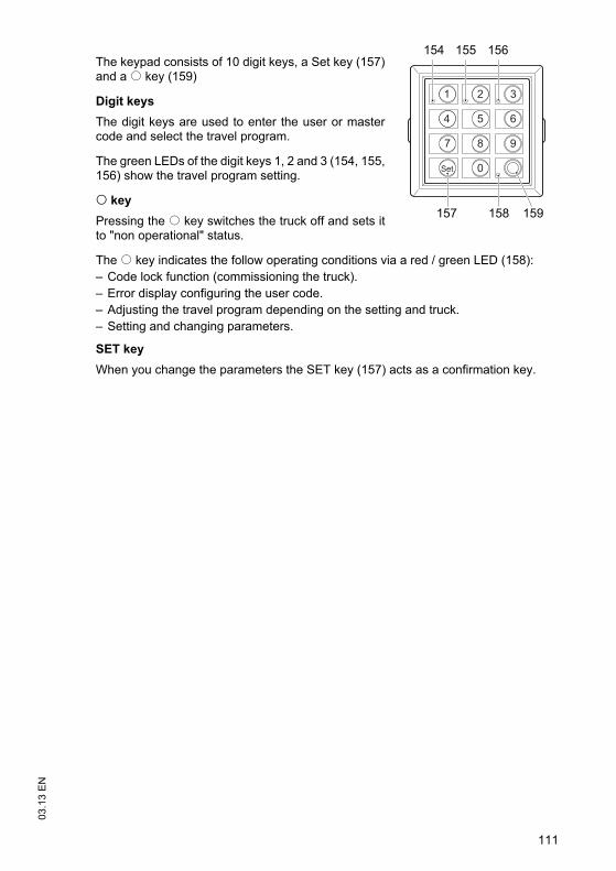
111
03.1
3 E
N
The keypad consists of 10 digit keys, a Set key (157)and a o key (159)
Digit keysThe digit keys are used to enter the user or mastercode and select the travel program.
The green LEDs of the digit keys 1, 2 and 3 (154, 155,156) show the travel program setting.
o keyPressing the o key switches the truck off and sets itto "non operational" status.
The o key indicates the follow operating conditions via a red / green LED (158):– Code lock function (commissioning the truck).– Error display configuring the user code. – Adjusting the travel program depending on the setting and truck.– Setting and changing parameters.
SET keyWhen you change the parameters the SET key (157) acts as a confirmation key.
1 2 3
4 5 6
7 8 9
0Set
157
154 155 156
159158o
03.1
3 E
N
112
6.1.2 Preparing the truck for operation with the keypad (CanCode)
Preparing the truck for operation by entering a valid operator code
Procedure• Pull the Emergency Disconnect to unlock it, see "Emergency Disconnect" on
page 80.The LED (158) lights up red.
• Enter the operator code with the digit keys.When you have entered a valid operator code the LED (158) lights up green, thetravel program selected is indicated by the corresponding LEDs (154,155,156) andthe truck is switched on.
Z If the LED (158) flashes red this means the wrong code has been entered. Enter thecode again.The Set key (157) has no function in operating mode.
6.1.3 Switching off the truck with the keypad (CanCode)
Switching off the truck
Procedure• Press the O key (159).
The truck is switched off and the LED (158) is lit red.
Z The truck can cut out automatically after a specified time. If no travel, steering orhydraulic operations are performed within a set time, the truck switches offautomatically. When you enter a valid code again the truck will be operational. Thecode lock parameter responsible for automatic cutout must be set, see "Setting theautomatic truck cutout (timeframe)" on page 123.

113
03.1
3 E
N6.1.4 Changing the master code
Z To change the length of the master code you must follow the procedure in "Chooselength of the new master code (4-6 digit) and add user codes", see "Choose lengthof the new master code (4-6 digit) and add user codes" on page 122. If there arestill user codes stored in the code lock, the master code to be changed must be thesame length as the saved user codes.
Requirements– To prepare the truck for operation, see "Preparing
the truck for operation with the keypad (CanCode)"on page 112.
Procedure• Press the O key (159).• Enter the valid master code with the digit keys.
When you enter the valid master code the LED(158) flashes green.
• Enter the parameters 0-0-0 with the digit keys. • Confirm with the SET key (157).
The LEDs (154,158) flash green.
• Enter the valid master code again with the digit keys.• Confirm with the SET key (157).
The LEDs (155,158) flash green.
• Enter the valid master code with the digit keys.Z The new master code must be different from existing user codes.
• Confirm with the SET key (157).The LEDs (156,158) flash green.
• Enter the new master code again with the digit keys.• Confirm with the SET key (157).
Wait until the LED (158) flashes green. The setting is saved.
• Press the O key (159).The truck is switched off and the LED (158) is lit red.
• Check the new master code:• Switch on the truck with the new master code, see "Preparing the truck for
operation with the keypad (CanCode)" on page 112When you enter the valid master code the LED (158) flashes green.
• Press the O key (159).The truck is switched off and the LED (158) is lit red.
1 2 3
4 5 6
7 8 9
0Set
157
154 155 156
159158

03.1
3 E
N
114
Error displays changing the master codeFor the following events the LED (158) flashes red:
Cause Remedy– New master code is already
occupied by a user code– Switch off the truck, see "Switching off the truck
with the keypad (CanCode)" on page 112.– Choose a different master code, see "Changing
the master code" on page 113.– Change the user code so that the required
master code can be used, see "Change operator code" on page 117.
– Delete the user code so that the required master code can be used, see "Delete individual user codes" on page 119.
– The master codes to be changed do not match
– Switch off the truck, see "Switching off the truck with the keypad (CanCode)" on page 112.
– Enter the master code again, see "Changing the master code" on page 113.
– The master code entered is not the same length as the user code
– Switch off the truck, see "Switching off the truck with the keypad (CanCode)" on page 112.
– Repeat the entry, making sure that the length of the master code matches that of the user code.

115
03.1
3 E
N6.1.5 Add operator code
Requirements– To prepare the truck for operation, see "Preparing
the truck for operation with the keypad (CanCode)"on page 112.
Procedure• Press the O key (159).• Enter the valid master code with the digit keys.
When you enter the valid master code the LED(158) flashes green.
• Enter the parameters 0-0-1 with the digit keys. • Confirm with the SET key (157).
The LEDs (155,158) flash green.
• Enter the new user code with the digit keys.Z The length (4-6 digit) of the new user code must be the same as that of the
previously entered master code. The new user code must also be different from theexisting master code.
• Confirm with the SET key (157).The LEDs (156,158) flash green.
• Enter the new user code again with the digit keys.• Confirm with the SET key (157).
Wait until the LED (158) flashes green. The setting is saved.
• Press the O key (159).The truck is switched off and the LED (158) is lit red.
• Check the new user code:• Switch on the truck with the new user code, see "Preparing the truck for operation
with the keypad (CanCode)" on page 112After entering the valid user code the LED (158) lights up green, the travelprogram setting is shown by the illumination of the corresponding LEDs(154,155,156) and the truck is switched on.
• Press the O key (159).The truck is switched off and the LED (158) is lit red.
1 2 3
4 5 6
7 8 9
0Set
157
154 155 156
159158
03.1
3 E
N
116
Error displays adding a user codeFor the following events the LED (158) flashes red:
Cause Remedy– The user code entered is not
the same length as the master code
– Switch off the truck, see "Switching off the truck with the keypad (CanCode)" on page 112.
– Repeat the entry, making sure that the master code is the same length as the user code.
– New user code is already occupied by a master code
– Switch off the truck, see "Switching off the truck with the keypad (CanCode)" on page 112.
– Choose a different user code, see "Add operator code" on page 115.
– The newly entered user codes do not match
– Switch off the truck, see "Switching off the truck with the keypad (CanCode)" on page 112.
– Add the user code again, see "Add operator code" on page 115.
– Code log full. – Switch off the truck, see "Switching off the truck with the keypad (CanCode)" on page 112.
– Delete individual user codes, see "Delete individual user codes" on page 119.
– Delete all user codes, see "Delete all user codes," on page 121.

117
03.1
3 E
N6.1.6 Change operator code
Requirements– To prepare the truck for operation, see "Preparing
the truck for operation with the keypad (CanCode)"on page 112.
Procedure• Press the O key (159).• Enter the valid master code with the digit keys.
When you enter the valid master code the LED(158) flashes green.
• Enter the parameters 0-0-2 with the digit keys. • Confirm with the SET key (157).
The LEDs (154,158) flash green.
• Enter the user code to be changed with the digit keys.• Confirm with the SET key (157).
The LEDs (155,158) flash green.
• Enter the new user code with the digit keys.Z The length (4-6 digit) of the new user code must be the same as that of the
previously entered master code. The new user code must also be different from theexisting master code.
• Confirm with the SET key (157).The LEDs (156,158) flash green.
• Enter the new user code again with the digit keys.• Confirm with the SET key (157).
Wait until the LED (158) flashes green. The setting is saved.
• Press the O key (159).The truck is switched off and the LED (158) is lit red.
• Check the new user code:• Switch on the truck with the new user code, see "Preparing the truck for operation
with the keypad (CanCode)" on page 112After entering the valid user code the LED (158) lights up green, the travelprogram setting is shown by the illumination of the corresponding LEDs(154,155,156) and the truck is switched on.
• Press the O key (159).The truck is switched off and the LED (158) is lit red.
1 2 3
4 5 6
7 8 9
0Set
157
154 155 156
159158
03.1
3 E
N
118
Error displays changing a user codeFor the following events the LED (158) flashes red:
Cause Remedy– The user code entered is not
the same length as the master code
– Switch off the truck, see "Switching off the truck with the keypad (CanCode)" on page 112.
– Repeat the entry, making sure that the master code is the same length as the user code.
– Operator code to be changed does not exist.
– Switch off the truck, see "Switching off the truck with the keypad (CanCode)" on page 112.
– Check the user code entered.– The user codes to be
changed do not match– Switch off the truck, see "Switching off the truck
with the keypad (CanCode)" on page 112.– Change the user code again, see "Change
operator code" on page 117.– Tried to change the operator
code to another user code that already exists.
– Switch off the truck, see "Switching off the truck with the keypad (CanCode)" on page 112.
– Choose a different user code, see "Change operator code" on page 117.
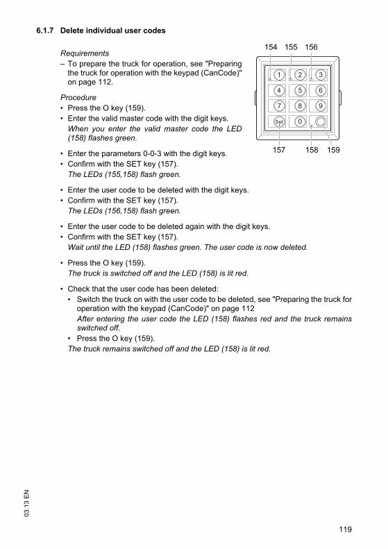
119
03.1
3 E
N6.1.7 Delete individual user codes
Requirements– To prepare the truck for operation, see "Preparing
the truck for operation with the keypad (CanCode)"on page 112.
Procedure• Press the O key (159).• Enter the valid master code with the digit keys.
When you enter the valid master code the LED(158) flashes green.
• Enter the parameters 0-0-3 with the digit keys. • Confirm with the SET key (157).
The LEDs (155,158) flash green.
• Enter the user code to be deleted with the digit keys.• Confirm with the SET key (157).
The LEDs (156,158) flash green.
• Enter the user code to be deleted again with the digit keys.• Confirm with the SET key (157).
Wait until the LED (158) flashes green. The user code is now deleted.
• Press the O key (159).The truck is switched off and the LED (158) is lit red.
• Check that the user code has been deleted:• Switch the truck on with the user code to be deleted, see "Preparing the truck for
operation with the keypad (CanCode)" on page 112After entering the user code the LED (158) flashes red and the truck remainsswitched off.
• Press the O key (159).The truck remains switched off and the LED (158) is lit red.
1 2 3
4 5 6
7 8 9
0Set
157
154 155 156
159158
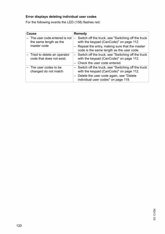
03.1
3 E
N
120
Error displays deleting individual user codesFor the following events the LED (158) flashes red:
Cause Remedy– The user code entered is not
the same length as the master code
– Switch off the truck, see "Switching off the truck with the keypad (CanCode)" on page 112.
– Repeat the entry, making sure that the master code is the same length as the user code.
– Tried to delete an operator code that does not exist.
– Switch off the truck, see "Switching off the truck with the keypad (CanCode)" on page 112.
– Check the user code entered.– The user codes to be
changed do not match– Switch off the truck, see "Switching off the truck
with the keypad (CanCode)" on page 112.– Delete the user code again, see "Delete
individual user codes" on page 119.
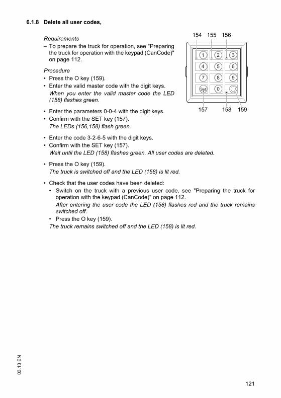
121
03.1
3 E
N6.1.8 Delete all user codes,
Requirements– To prepare the truck for operation, see "Preparing
the truck for operation with the keypad (CanCode)"on page 112.
Procedure• Press the O key (159).• Enter the valid master code with the digit keys.
When you enter the valid master code the LED(158) flashes green.
• Enter the parameters 0-0-4 with the digit keys. • Confirm with the SET key (157).
The LEDs (156,158) flash green.
• Enter the code 3-2-6-5 with the digit keys.• Confirm with the SET key (157).
Wait until the LED (158) flashes green. All user codes are deleted.
• Press the O key (159).The truck is switched off and the LED (158) is lit red.
• Check that the user codes have been deleted:• Switch on the truck with a previous user code, see "Preparing the truck for
operation with the keypad (CanCode)" on page 112.After entering the user code the LED (158) flashes red and the truck remainsswitched off.
• Press the O key (159).The truck remains switched off and the LED (158) is lit red.
1 2 3
4 5 6
7 8 9
0Set
157
154 155 156
159158
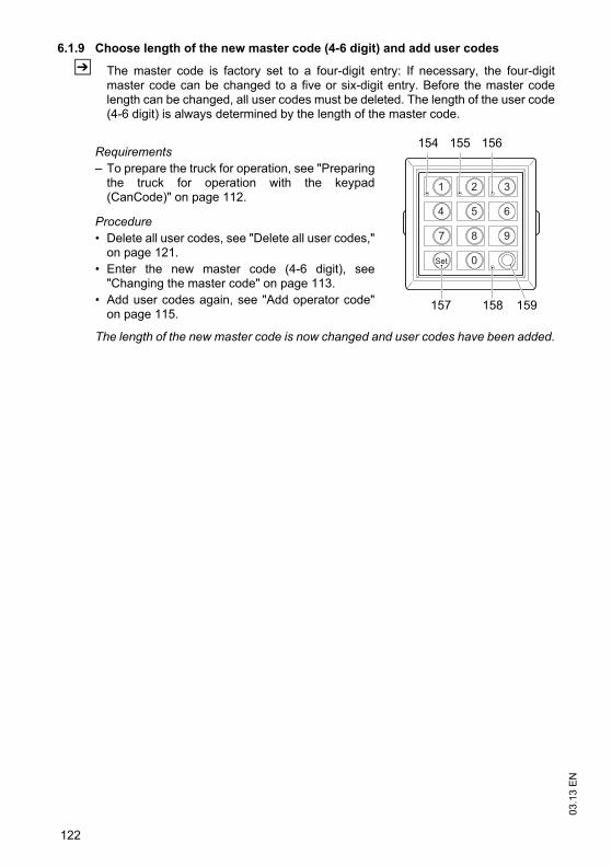
03.1
3 E
N
122
6.1.9 Choose length of the new master code (4-6 digit) and add user codes
Z The master code is factory set to a four-digit entry: If necessary, the four-digitmaster code can be changed to a five or six-digit entry. Before the master codelength can be changed, all user codes must be deleted. The length of the user code(4-6 digit) is always determined by the length of the master code.
Requirements– To prepare the truck for operation, see "Preparing
the truck for operation with the keypad(CanCode)" on page 112.
Procedure• Delete all user codes, see "Delete all user codes,"
on page 121.• Enter the new master code (4-6 digit), see
"Changing the master code" on page 113.• Add user codes again, see "Add operator code"
on page 115.
The length of the new master code is now changed and user codes have been added.
1 2 3
4 5 6
7 8 9
0Set
157
154 155 156
159158
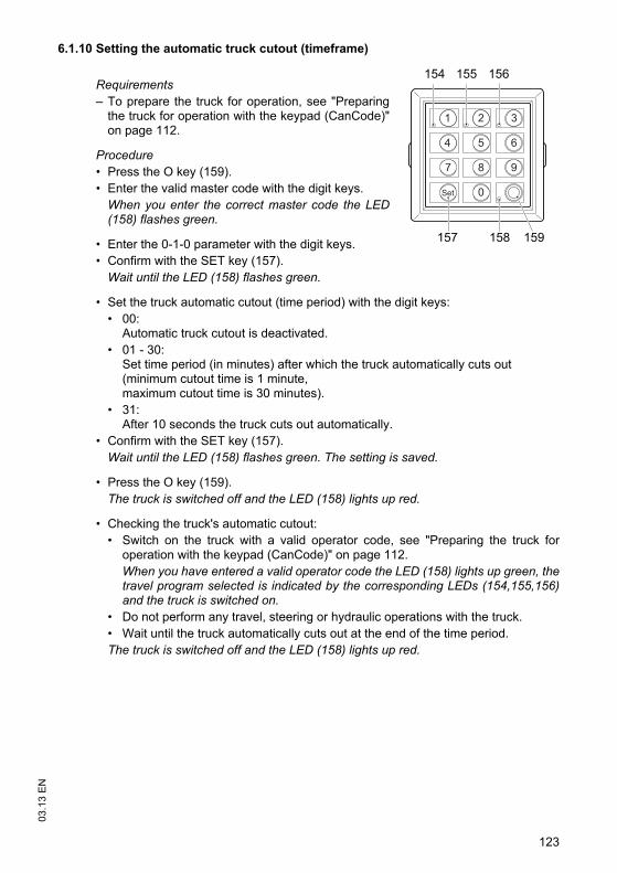
123
03.1
3 E
N6.1.10 Setting the automatic truck cutout (timeframe)
Requirements– To prepare the truck for operation, see "Preparing
the truck for operation with the keypad (CanCode)"on page 112.
Procedure• Press the O key (159).• Enter the valid master code with the digit keys.
When you enter the correct master code the LED(158) flashes green.
• Enter the 0-1-0 parameter with the digit keys. • Confirm with the SET key (157).
Wait until the LED (158) flashes green.
• Set the truck automatic cutout (time period) with the digit keys:• 00:
Automatic truck cutout is deactivated.• 01 - 30:
Set time period (in minutes) after which the truck automatically cuts out(minimum cutout time is 1 minute,maximum cutout time is 30 minutes).
• 31:After 10 seconds the truck cuts out automatically.
• Confirm with the SET key (157).Wait until the LED (158) flashes green. The setting is saved.
• Press the O key (159).The truck is switched off and the LED (158) lights up red.
• Checking the truck's automatic cutout:• Switch on the truck with a valid operator code, see "Preparing the truck for
operation with the keypad (CanCode)" on page 112.When you have entered a valid operator code the LED (158) lights up green, thetravel program selected is indicated by the corresponding LEDs (154,155,156)and the truck is switched on.
• Do not perform any travel, steering or hydraulic operations with the truck.• Wait until the truck automatically cuts out at the end of the time period.The truck is switched off and the LED (158) lights up red.
1 2 3
4 5 6
7 8 9
0Set
157
154 155 156
159158

03.1
3 E
N
124
Error displays setting the automatic cutout period of the truckFor the following events the LED (158) flashes red:
Cause Remedy– Cutout time entered is out of
range– Switch off the truck, see "Switching off the truck
with the keypad (CanCode)" on page 112.– Enter the time again while making sure it is
within range.
125
03.1
3 E
N6.1.11 Assigning the travel program
The travel programs are fixed to the user code and can be released or blocked with aconfiguration code. The configuration code can also be used to assign a starting travelprogram to each user code.
Z The starting travel program is the travel program that is activated when the truck isswitched on and is displayed by the (154,155,156) LEDs. LED (154) lit = travel program 1 activated LED (155) lit = travel program 2 activated LED (156) lit = travel program 3 activated
The configuration code is four-digit and is comprised as follows:– 1st digit: Specifies the authorisation for travel program 1:– 2nd digit: Specifies the authorisation for travel program 2:– 3rd digit: Specifies the authorisation for travel program 3:– 4. digit: Specifying the starting travel program
When you add or change a user code all travel programs are enabled, the startingtravel program is travel program 2.
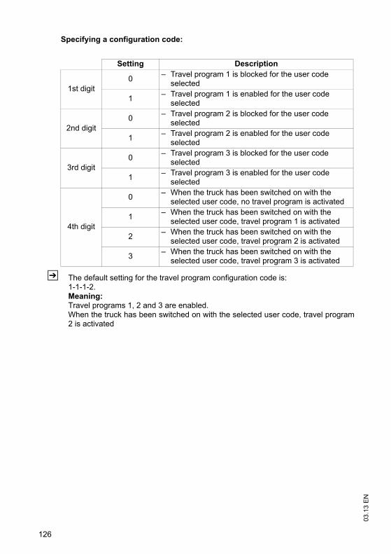
03.1
3 E
N
126
Specifying a configuration code:
Z The default setting for the travel program configuration code is:1-1-1-2.Meaning:Travel programs 1, 2 and 3 are enabled.When the truck has been switched on with the selected user code, travel program2 is activated
Setting Description
1st digit0 – Travel program 1 is blocked for the user code
selected
1 – Travel program 1 is enabled for the user code selected
2nd digit0 – Travel program 2 is blocked for the user code
selected
1 – Travel program 2 is enabled for the user code selected
3rd digit0 – Travel program 3 is blocked for the user code
selected
1 – Travel program 3 is enabled for the user code selected
4th digit
0 – When the truck has been switched on with the selected user code, no travel program is activated
1 – When the truck has been switched on with the selected user code, travel program 1 is activated
2 – When the truck has been switched on with the selected user code, travel program 2 is activated
3 – When the truck has been switched on with the selected user code, travel program 3 is activated
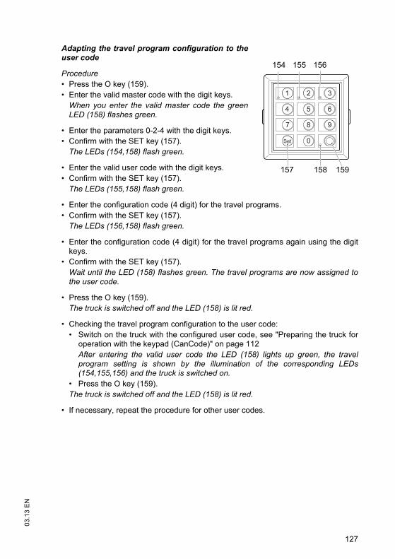
127
03.1
3 E
N
Adapting the travel program configuration to theuser code
Procedure• Press the O key (159).• Enter the valid master code with the digit keys.
When you enter the valid master code the greenLED (158) flashes green.
• Enter the parameters 0-2-4 with the digit keys. • Confirm with the SET key (157).
The LEDs (154,158) flash green.
• Enter the valid user code with the digit keys.• Confirm with the SET key (157).
The LEDs (155,158) flash green.
• Enter the configuration code (4 digit) for the travel programs.• Confirm with the SET key (157).
The LEDs (156,158) flash green.
• Enter the configuration code (4 digit) for the travel programs again using the digitkeys.
• Confirm with the SET key (157).Wait until the LED (158) flashes green. The travel programs are now assigned tothe user code.
• Press the O key (159).The truck is switched off and the LED (158) is lit red.
• Checking the travel program configuration to the user code:• Switch on the truck with the configured user code, see "Preparing the truck for
operation with the keypad (CanCode)" on page 112After entering the valid user code the LED (158) lights up green, the travelprogram setting is shown by the illumination of the corresponding LEDs(154,155,156) and the truck is switched on.
• Press the O key (159).The truck is switched off and the LED (158) is lit red.
• If necessary, repeat the procedure for other user codes.
1 2 3
4 5 6
7 8 9
0Set
157
154 155 156
159158

03.1
3 E
N
128
Error displays configuring the travel programsFor the following events the LED (158) flashes red:
Cause Remedy– Blocked travel program
defined as start travel program
– Switch off the truck, see "Switching off the truck with the keypad (CanCode)" on page 112.
– Try again, making sure the configuration code is entered correctly.
129
03.1
3 E
N6.2 Assistance systems
The Access, Drive and Lift Control systems help the driver operate the truck withregard to safety regulations, see "Safety regulations for truck operation" on page 74of the present operating instructions.
Travel conductThe operator must adapt the travel speed to local conditions. The truck must be drivenat slow speed when negotiating bends or narrow passageways, when passingthrough swing doors and at blind spots. The operator must always observe anadequate braking distance between the forklift truck and the vehicle in front and mustbe in control of the truck at all times. Abrupt stopping (except in emergencies), rapidU turns and overtaking at dangerous or blind spots are not permitted. Do not lean outor reach beyond the working and operating area.
6.2.1 Access Control
The truck is only released for operation if:1)The operator is seated. 2)The truck is switched on via the key switch (ISM o / CanCode o).3)He is wearing the seat belt.
Z If the driver vacates the seat for a short while and the truck is not in the "neutral lock"position (see "Travel" on page 81), the truck can be operated again when he returns(seat occupied) and puts the seat belt back on again, without having to apply thekey switch again.
Z If travel is not enabled, the seat switch indicator lights up (98). Items 1 to 3 must beperformed again in the order listed.
03.1
3 E
N
130
6.2.2 Drive Control
This option restricts the travel speed of the truck depending on of the steer angle.From a factory-set lift height (approx. 1.50 metres) the maximum travel speed isreduced to walking pace (approx. 3 km/h) and the slow travel indicator is activated.When the forks fall below this height, the truck accelerates at reduced levels to thespeed prescribed by the accelerator pedal to prevent sudden acceleration whenchanging from slow travel to normal travel. Normal acceleration is only activated againwhen the speed prescribed by the accelerator pedal has been reached or if theaccelerator pedal is set to the 0 position.
Z In addition to the daily checks before starting, see "Checks and operations to beperformed before starting daily operation" on page 65 the driver must carry out thefollowing checks:
– Lift the empty load handler beyond the reference lift height and check if the slowtravel display lights up.
– Steering when the truck is stationary: check if the steering wheel display is working.
6.2.3 Lift Control
This option includes Drive Control and also monitors and controls the mast functions:
Tilt speed reduction as a function of the lift height (from approx. 1.5 m lift height).– When the load handler is lowered below the limit height, the tilt speed increases
again.
Optional:– Tilt angle display, see "Tilt angle display" on page 139.
In addition to the daily checks before starting, the driver must carry out thefollowing checks:
Procedure• Lift the empty load handler beyond the reference lift height and check if the slow
travel display lights up and the tilt speed is clearly reduced.• Steering when the truck is stationary: check if the steering wheel display is working.• Check the tilt angle display by tilting forward and back.
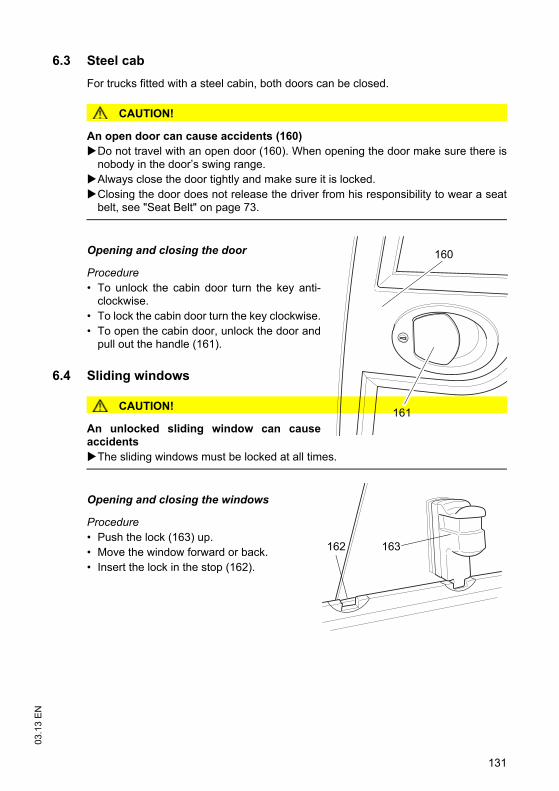
131
03.1
3 E
N
6.3 Steel cabFor trucks fitted with a steel cabin, both doors can be closed.
CAUTION!
An open door can cause accidents (160)Do not travel with an open door (160). When opening the door make sure there isnobody in the door’s swing range.Always close the door tightly and make sure it is locked.Closing the door does not release the driver from his responsibility to wear a seatbelt, see "Seat Belt" on page 73.
Opening and closing the door
Procedure• To unlock the cabin door turn the key anti-
clockwise.• To lock the cabin door turn the key clockwise.• To open the cabin door, unlock the door and
pull out the handle (161).
6.4 Sliding windows
CAUTION!
An unlocked sliding window can causeaccidents
The sliding windows must be locked at all times.
Opening and closing the windows
Procedure• Push the lock (163) up.• Move the window forward or back.• Insert the lock in the stop (162).
161
160
163162
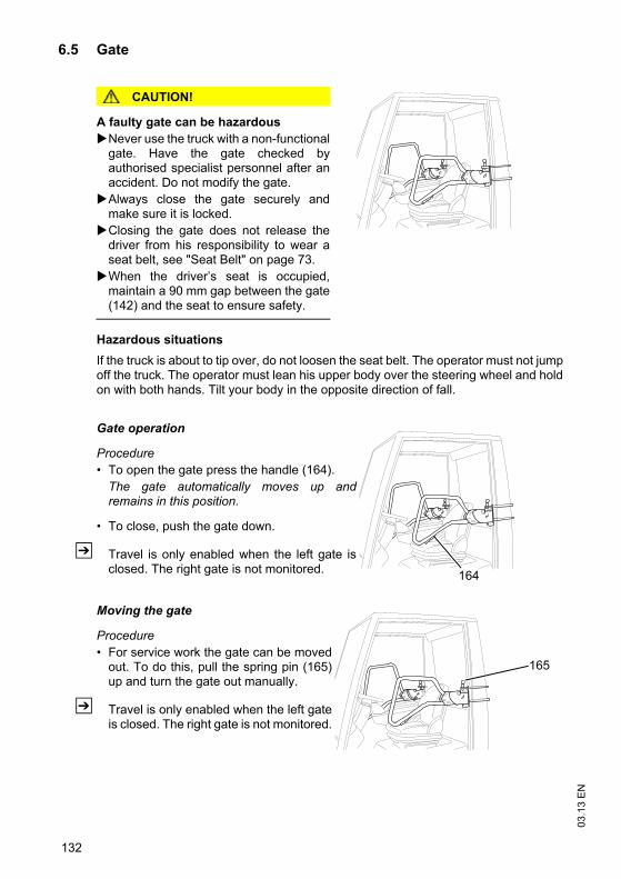
03.1
3 E
N
132
6.5 Gate
CAUTION!
A faulty gate can be hazardousNever use the truck with a non-functionalgate. Have the gate checked byauthorised specialist personnel after anaccident. Do not modify the gate.Always close the gate securely andmake sure it is locked.Closing the gate does not release thedriver from his responsibility to wear aseat belt, see "Seat Belt" on page 73.When the driver’s seat is occupied,maintain a 90 mm gap between the gate(142) and the seat to ensure safety.
Hazardous situationsIf the truck is about to tip over, do not loosen the seat belt. The operator must not jumpoff the truck. The operator must lean his upper body over the steering wheel and holdon with both hands. Tilt your body in the opposite direction of fall.
Gate operation
Procedure• To open the gate press the handle (164).
The gate automatically moves up andremains in this position.
• To close, push the gate down.
Z Travel is only enabled when the left gate isclosed. The right gate is not monitored.
Moving the gate
Procedure• For service work the gate can be moved
out. To do this, pull the spring pin (165)up and turn the gate out manually.
Z Travel is only enabled when the left gateis closed. The right gate is not monitored.
164
165

133
03.1
3 E
N6.6 Panel door
CAUTION!
An open door can cause accidents (160)Do not travel with an open door (160). When opening the door make sure there isnobody in the door’s swing range.Always close the door tightly and make sure it is locked.Closing the door does not release the driver from his responsibility to wear a seatbelt, see "Seat Belt" on page 73.
Hazardous situationsIf the truck is about to tip over, do not loosen theseat belt. The operator must not jump off thetruck. The operator must lean his upper bodyover the steering wheel and hold on with bothhands. Tilt your body in the opposite direction offall.
Requirements– On trucks with a door monitoring sensor, travel
is only enabled when the panel door is closed(o).
Procedure• Pull the handle (166) towards the operator
position, the door swings open.• Pull the door (160) towards the operator; the door closes.
6.7 Operator position extension
DANGER!
Altering the tilt resistance can be dangerousThe lateral tilt resistance reduces with a higher truck centre of gravity. The height above the overhead guard (h6) increases by 300 mm, see "Dimensions"on page 22.
Adapt the travel speed of the truck, in particular when cornering.
Z For entry and exit see "Entry and exit" on page 67.
160166
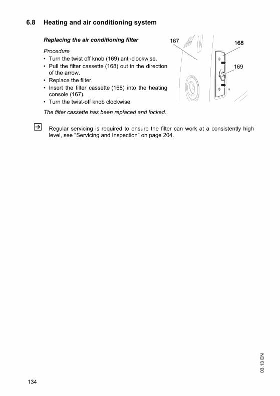
03.1
3 E
N
134
6.8 Heating and air conditioning system
Replacing the air conditioning filter
Procedure• Turn the twist off knob (169) anti-clockwise. • Pull the filter cassette (168) out in the direction
of the arrow.• Replace the filter.• Insert the filter cassette (168) into the heating
console (167).• Turn the twist-off knob clockwise
The filter cassette has been replaced and locked.
Z Regular servicing is required to ensure the filter can work at a consistently highlevel, see "Servicing and Inspection" on page 204.
167 168168
169
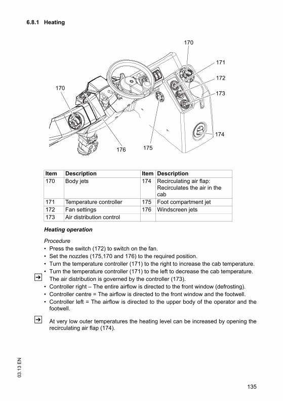
135
03.1
3 E
N6.8.1 Heating
Heating operation
Procedure• Press the switch (172) to switch on the fan.• Set the nozzles (175,170 and 176) to the required position.• Turn the temperature controller (171) to the right to increase the cab temperature.• Turn the temperature controller (171) to the left to decrease the cab temperature.
Z The air distribution is governed by the controller (173). • Controller right – The entire airflow is directed to the front window (defrosting).• Controller centre = The airflow is directed to the front window and the footwell.• Controller left = The airflow is directed to the upper body of the operator and the
footwell.
Z At very low outer temperatures the heating level can be increased by opening therecirculating air flap (174).
Item Description Item Description170 Body jets 174 Recirculating air flap:
Recirculates the air in the cab
171 Temperature controller 175 Foot compartment jet172 Fan settings 176 Windscreen jets173 Air distribution control
174
170
170
172
175
173
176
171
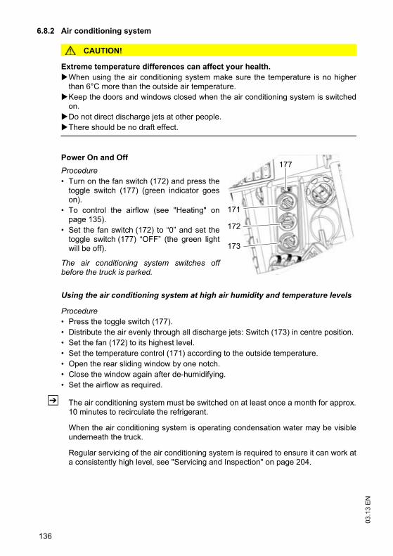
03.1
3 E
N
136
6.8.2 Air conditioning system
CAUTION!
Extreme temperature differences can affect your health. When using the air conditioning system make sure the temperature is no higherthan 6°C more than the outside air temperature.Keep the doors and windows closed when the air conditioning system is switchedon.Do not direct discharge jets at other people.There should be no draft effect.
Power On and OffProcedure• Turn on the fan switch (172) and press the
toggle switch (177) (green indicator goeson).
• To control the airflow (see "Heating" onpage 135).
• Set the fan switch (172) to “0” and set thetoggle switch (177) “OFF” (the green lightwill be off).
The air conditioning system switches offbefore the truck is parked.
Using the air conditioning system at high air humidity and temperature levels
Procedure• Press the toggle switch (177).• Distribute the air evenly through all discharge jets: Switch (173) in centre position.• Set the fan (172) to its highest level.• Set the temperature control (171) according to the outside temperature.• Open the rear sliding window by one notch.• Close the window again after de-humidifying.• Set the airflow as required.
Z The air conditioning system must be switched on at least once a month for approx.10 minutes to recirculate the refrigerant.
When the air conditioning system is operating condensation water may be visibleunderneath the truck.
Regular servicing of the air conditioning system is required to ensure it can work ata consistently high level, see "Servicing and Inspection" on page 204.
171
173
172
177
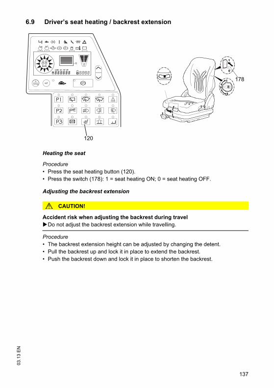
137
03.1
3 E
N6.9 Driver’s seat heating / backrest extension
Heating the seat
Procedure• Press the seat heating button (120).• Press the switch (178): 1 = seat heating ON; 0 = seat heating OFF.
Adjusting the backrest extension
CAUTION!
Accident risk when adjusting the backrest during travelDo not adjust the backrest extension while travelling.
Procedure• The backrest extension height can be adjusted by changing the detent.• Pull the backrest up and lock it in place to extend the backrest. • Push the backrest down and lock it in place to shorten the backrest.
178
km/h
R
120
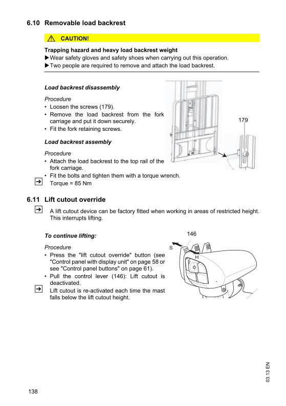
03.1
3 E
N
138
6.10 Removable load backrest
CAUTION!
Trapping hazard and heavy load backrest weightWear safety gloves and safety shoes when carrying out this operation.Two people are required to remove and attach the load backrest.
Load backrest disassembly
Procedure• Loosen the screws (179).• Remove the load backrest from the fork
carriage and put it down securely.• Fit the fork retaining screws.
Load backrest assembly
Procedure• Attach the load backrest to the top rail of the
fork carriage.• Fit the bolts and tighten them with a torque wrench.
Z Torque = 85 Nm
6.11 Lift cutout overrideZ A lift cutout device can be factory fitted when working in areas of restricted height.
This interrupts lifting.
To continue lifting:
Procedure• Press the "lift cutout override" button (see
"Control panel with display unit" on page 58 orsee "Control panel buttons" on page 61).
• Pull the control lever (146): Lift cutout isdeactivated.
Z Lift cutout is re-activated each time the mastfalls below the lift cutout height.
179
S
H
146
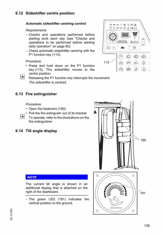
139
03.1
3 E
N6.12 Sideshifter centre position
Automatic sideshifter centring control
Requirements– Checks and operations performed before
starting work each day (see "Checks andoperations to be performed before startingdaily operation" on page 65).
– Check automatic sideshifter centring with theP1 function key (113).
Procedure• Press and hold down on the P1 function
key (113). The sideshifter moves to thecentre position.
Z Releasing the P1 function key interrupts the movement.The sideshifter is centred.
6.13 Fire extinguisher
Procedure• Open the fasteners (180)• Pull the fire extinguish out of its bracket
Z To operate, refer to the illustrations on thefire extinguisher
6.14 Tilt angle display
NOTE
The current tilt angle is shown in anadditional display that is attached on theright of the dashboard.
– The green LED (181) indicates thevertical position to the ground.
km/h
R
113
180
181
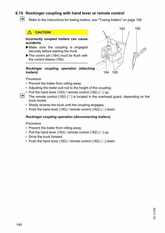
03.1
3 E
N
140
6.15 Rockinger coupling with hand lever or remote controlZ Refer to the instructions for towing trailers, see "Towing trailers" on page 108.
CAUTION!
Incorrectly coupled trailers can causeaccidents
Make sure the coupling is engagedsecurely before starting the truck.The contro pin (184) must be flush withthe control sleeve (185).
Rockinger coupling operation (attachingtrailers)
Procedure• Prevent the trailer from rolling away.• Adjusting the trailer pull rod to the height of the coupling.• Pull the hand lever (183) / remote control (182) (o) up.
Z The remote control (182) (o) is located in the overhead guard, depending on thetruck model.
• Slowly reverse the truck until the coupling engages.• Push the hand lever (183) / remote control (182) (o) down.
Rockinger coupling operation (disconnecting trailers)
Procedure• Prevent the trailer from rolling away.• Pull the hand lever (183) / remote control (182) (o) up.• Drive the truck forward.• Push the hand lever (183) / remote control (182) (o) down.
183 182
184 185
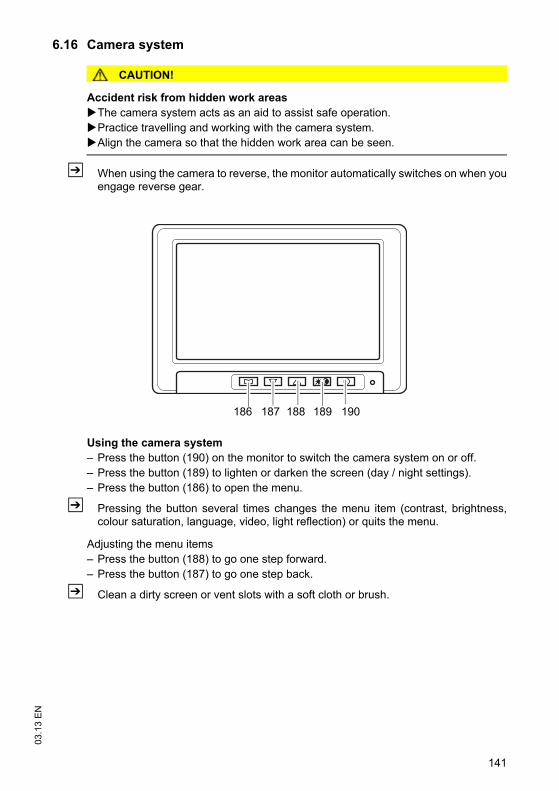
141
03.1
3 E
N6.16 Camera system
CAUTION!
Accident risk from hidden work areasThe camera system acts as an aid to assist safe operation.Practice travelling and working with the camera system.Align the camera so that the hidden work area can be seen.
Z When using the camera to reverse, the monitor automatically switches on when youengage reverse gear.
Using the camera system– Press the button (190) on the monitor to switch the camera system on or off.– Press the button (189) to lighten or darken the screen (day / night settings).– Press the button (186) to open the menu.
Z Pressing the button several times changes the menu item (contrast, brightness,colour saturation, language, video, light reflection) or quits the menu.
Adjusting the menu items– Press the button (188) to go one step forward.– Press the button (187) to go one step back.
Z Clean a dirty screen or vent slots with a soft cloth or brush.
186 187 188 190189
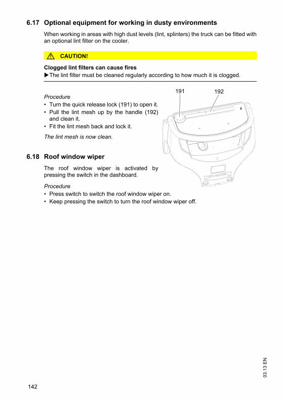
03.1
3 E
N
142
6.17 Optional equipment for working in dusty environmentsWhen working in areas with high dust levels (lint, splinters) the truck can be fitted withan optional lint filter on the cooler.
CAUTION!
Clogged lint filters can cause firesThe lint filter must be cleaned regularly according to how much it is clogged.
Procedure• Turn the quick release lock (191) to open it.• Pull the lint mesh up by the handle (192)
and clean it.• Fit the lint mesh back and lock it.
The lint mesh is now clean.
6.18 Roof window wiperThe roof window wiper is activated bypressing the switch in the dashboard.
Procedure• Press switch to switch the roof window wiper on.• Keep pressing the switch to turn the roof window wiper off.
191 192
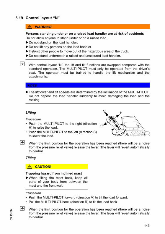
143
03.1
3 E
N
6.19 Control layout “N”
WARNING!
Persons standing under or on a raised load handler are at risk of accidentsDo not allow anyone to stand under or on a raised load.
Do not stand on the load handler.Do not lift any persons on the load handler.Instruct other people to move out of the hazardous area of the truck.Do not stand underneath a raised and unsecured load handler.
Z With control layout “N”, the lift and tilt functions are swapped compared with thestandard operation. The MULTI-PILOT must only be operated from the driver’sseat. The operator must be trained to handle the lift mechanism and theattachments.
NOTE
The lift/lower and tilt speeds are determined by the inclination of the MULTI-PILOT.Do not deposit the load handler suddenly to avoid damaging the load and theracking.
Lifting
Procedure• Push the MULTI-PILOT to the right (direction
H) to raise the load.• Push the MULTI-PILOT to the left (direction S)
to lower the load.
Z When the limit position for the operation has been reached (there will be a noisefrom the pressure relief valve) release the lever. The lever will revert automaticallyto neutral.
Tilting
CAUTION!
Trapping hazard from inclined mastWhen tilting the mast back, keep allparts of your body from between themast and the front wall.
Procedure• Push the MULTI-PILOT forward (direction V) to tilt the load forward.• Pull the MULTI-PILOT back (direction R) to tilt the load back.
Z When the limit position for the operation has been reached (there will be a noisefrom the pressure relief valve) release the lever. The lever will revert automaticallyto neutral.
R
V H
S
03.1
3 E
N
144
7 Troubleshooting
7.1 TroubleshootingThis chapter enables the operator to localize and rectify basic faults or the results ofincorrect operation himself. When trying to locate a fault, proceed in the order shownin the remedy table.
Z If, after carrying out the following remedial action, the truck cannot be restored tooperation or if a fault in the electronics system is displayed with a correspondingerror code, contact the manufacturer’s service department.Troubleshooting must only be performed by the manufacturer’s customer servicedepartment. The manufacturer has a service department specially trained for thesetasks.In order for customer services to react quickly and specifically to the fault, thefollowing information is essential:- Truck serial number- Error number on the display unit (if applicable)- Error description- Current location of truck.
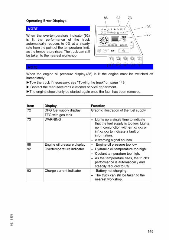
145
03.1
3 E
N
Operating Error Displays
NOTE
When the overtemperature indicator (92)is lit the performance of the truckautomatically reduces to 0% at a steadyrate from the point of the temperature limit,as the temperature rises. The truck can stillbe taken to the nearest workshop.
NOTE
When the engine oil pressure display (88) is lit the engine must be switched offimmediately.
Tow the truck if necessary, see "Towing the truck" on page 149. Contact the manufacturer's customer service department.The engine should only be started again once the fault has been removed.
Item Display Function72 DFG fuel supply display Graphic illustration of the fuel supply.
TFG with gas tank73 WARNING – Lights up a single time to indicate
that the fuel supply is too low. Lights up in conjunction with err xx xxx or inf xx xxx to indicate a fault or information.
– A warning signal sounds.88 Engine oil pressure display – Engine oil pressure too low.92 Overtemperature indicator – Hydraulic oil temperature too high.
– Coolant temperature too high.– As the temperature rises, the truck's
performance is automatically and steadily reduced to 0%.
93 Charge current indicator – Battery not charging.– The truck can still be taken to the
nearest workshop.
km/h
R
739288
93
72
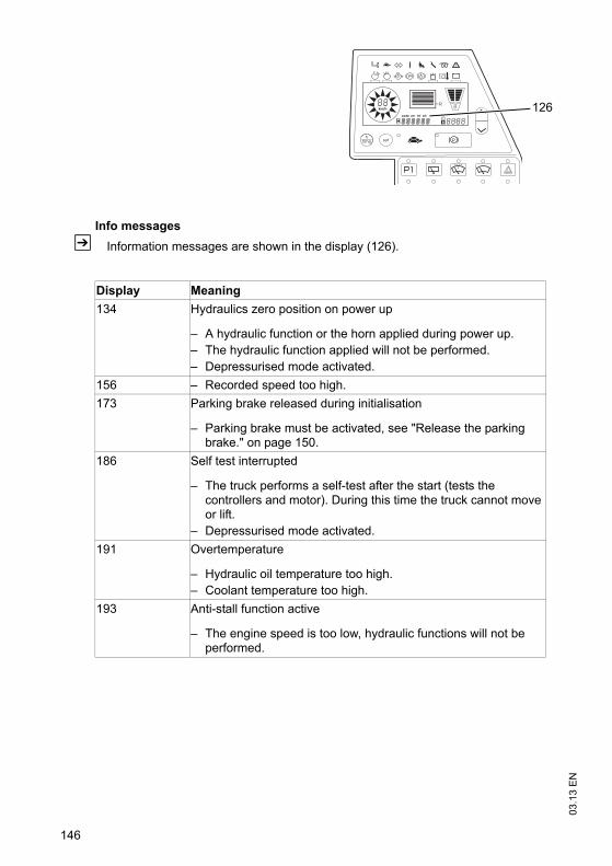
03.1
3 E
N
146
Info messagesZ Information messages are shown in the display (126).
Display Meaning134 Hydraulics zero position on power up
– A hydraulic function or the horn applied during power up.– The hydraulic function applied will not be performed.– Depressurised mode activated.
156 – Recorded speed too high.173 Parking brake released during initialisation
– Parking brake must be activated, see "Release the parking brake." on page 150.
186 Self test interrupted
– The truck performs a self-test after the start (tests the controllers and motor). During this time the truck cannot move or lift.
– Depressurised mode activated.191 Overtemperature
– Hydraulic oil temperature too high.– Coolant temperature too high.
193 Anti-stall function active
– The engine speed is too low, hydraulic functions will not be performed.
km/h
R 126
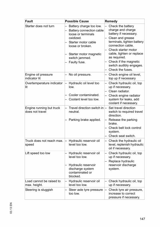
147
03.1
3 E
N
Fault Possible Cause RemedyStarter does not turn – Battery charge too low.
– Battery connection cable loose or terminals oxidized.
– Starter motor cable loose or broken.
– Starter motor magnetic switch jammed.
– Faulty fuse.
– Check the battery charge and charge battery if necessary.
– Clean and grease terminals, tighten battery connection cable.
– Check starter motor cable, tighten or replace as required.
– Check if the magnetic switch audibly engages.
– Check the fuses.Engine oil pressure indicator lit
– No oil pressure. – Check engine oil level, top up if necessary
Overtemperature indicator lit
– Hydraulic oil level too low.
– Cooler contaminated.– Coolant level too low.
– Check hydraulic oil, top up if necessary.
– Clean radiator.– Check engine radiator
system for leaks, add coolant if necessary.
Engine running but truck does not travel
– Travel direction switch in neutral.
– Parking brake applied.
– Set travel direction switch to required travel direction.
– Release the parking brake.
– Check belt lock control system.
– Check seat switch.Truck does not reach max. speed
– Hydraulic reservoir oil level too low.
– Check the hydraulic oil level, replenish hydraulic oil if necessary.
Lift speed too low – Hydraulic reservoir oil level too low.
– Hydraulic reservoir discharge system contaminated or blocked.
– Check hydraulic oil, top up if necessary.
– Replace hydraulic reservoir discharge system.
Load cannot be raised to max. height.
– Hydraulic reservoir oil level too low.
– Check hydraulic oil, top up if necessary.
Steering is sluggish – Steer axle tyre pressure too low.
– Check tyre air pressure, increase to correct pressure if necessary.
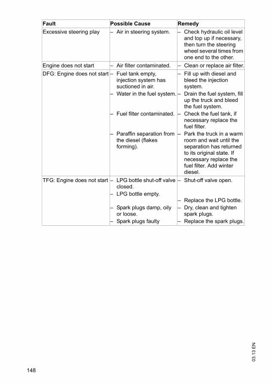
03.1
3 E
N
148
Excessive steering play – Air in steering system. – Check hydraulic oil level and top up if necessary, then turn the steering wheel several times from one end to the other.
Engine does not start – Air filter contaminated. – Clean or replace air filter.DFG: Engine does not start – Fuel tank empty,
injection system has suctioned in air.
– Water in the fuel system.
– Fuel filter contaminated.
– Paraffin separation from the diesel (flakes forming).
– Fill up with diesel and bleed the injection system.
– Drain the fuel system, fill up the truck and bleed the fuel system.
– Check the fuel tank, if necessary replace the fuel filter.
– Park the truck in a warm room and wait until the separation has returned to its original state. If necessary replace the fuel filter. Add winter diesel.
TFG: Engine does not start – LPG bottle shut-off valve closed.
– LPG bottle empty.
– Spark plugs damp, oily or loose.
– Spark plugs faulty
– Shut-off valve open.
– Replace the LPG bottle.– Dry, clean and tighten
spark plugs.– Replace the spark plugs.
Fault Possible Cause Remedy
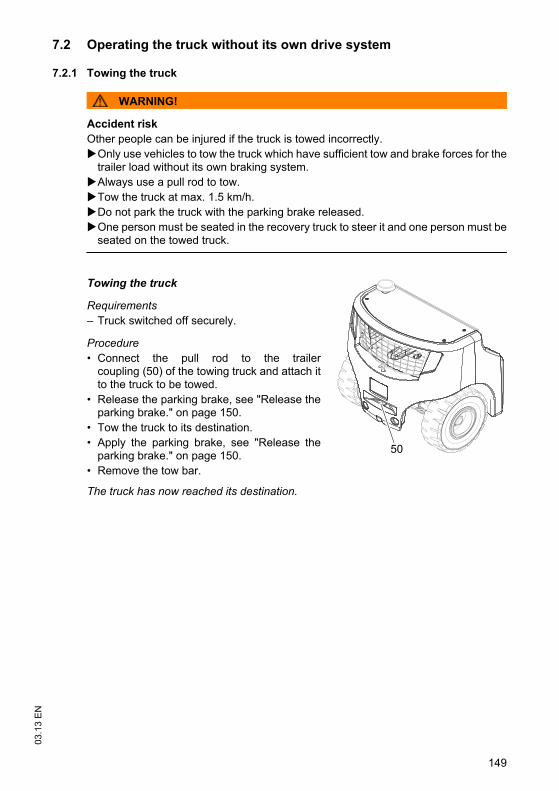
149
03.1
3 E
N7.2 Operating the truck without its own drive system
7.2.1 Towing the truck
WARNING!
Accident riskOther people can be injured if the truck is towed incorrectly.
Only use vehicles to tow the truck which have sufficient tow and brake forces for thetrailer load without its own braking system.Always use a pull rod to tow.Tow the truck at max. 1.5 km/h.Do not park the truck with the parking brake released.One person must be seated in the recovery truck to steer it and one person must beseated on the towed truck.
Towing the truck
Requirements– Truck switched off securely.
Procedure• Connect the pull rod to the trailer
coupling (50) of the towing truck and attach itto the truck to be towed.
• Release the parking brake, see "Release theparking brake." on page 150.
• Tow the truck to its destination.• Apply the parking brake, see "Release the
parking brake." on page 150.• Remove the tow bar.
The truck has now reached its destination.
50
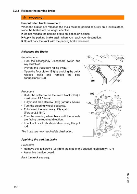
03.1
3 E
N
150
7.2.2 Release the parking brake.
WARNING!
Uncontrolled truck movementWhen the brakes are released the truck must be parked securely on a level surface,since the brakes are no longer effective.
Do not release the parking brake on slopes or inclines.Apply the parking brake again when you reach your destination.Do not park the truck with the parking brake released.
Releasing the Brake
Requirements– Turn the Emergency Disconnect switch and
key switch off.– Prevent the truck from rolling away.– Open the floor plate (193) by undoing the quick
release locks and remove the plugconnections (194).
Procedure• Undo the setscrew on the valve block (195) a
maximum of 1.5 turns.• Fully insert the setscrew (196) (torque 2.5 Nm).• Turn the steering wheel clockwise.• Fully insert the setscrew (195) again
(Torque 2.5 Nm).• Turn the steering wheel back until the wheels
are facing the required direction.• Tow the truck to its destination using the pull
rod.
The truck has now reached its destination.
Applying the parking brake
Procedure• Remove the setscrew (196) from the stop of the cheese head screw (197)• Assemble the floorboard.
Park the truck securely.
193
194 194
195
196
197
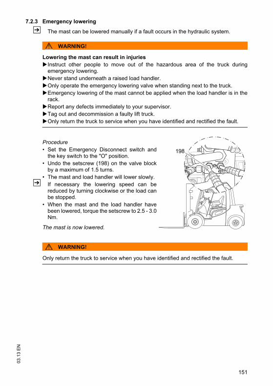
151
03.1
3 E
N7.2.3 Emergency lowering
Z The mast can be lowered manually if a fault occurs in the hydraulic system.
WARNING!
Lowering the mast can result in injuriesInstruct other people to move out of the hazardous area of the truck duringemergency lowering.Never stand underneath a raised load handler.Only operate the emergency lowering valve when standing next to the truck.Emergency lowering of the mast cannot be applied when the load handler is in therack.Report any defects immediately to your supervisor.Tag out and decommission a faulty lift truck.Only return the truck to service when you have identified and rectified the fault.
Procedure• Set the Emergency Disconnect switch and
the key switch to the "O" position.• Undo the setscrew (198) on the valve block
by a maximum of 1.5 turns.• The mast and load handler will lower slowly.
Z If necessary the lowering speed can bereduced by turning clockwise or the load canbe stopped.
• When the mast and the load handler havebeen lowered, torque the setscrew to 2.5 - 3.0Nm.
The mast is now lowered.
WARNING!
Only return the truck to service when you have identified and rectified the fault.
198
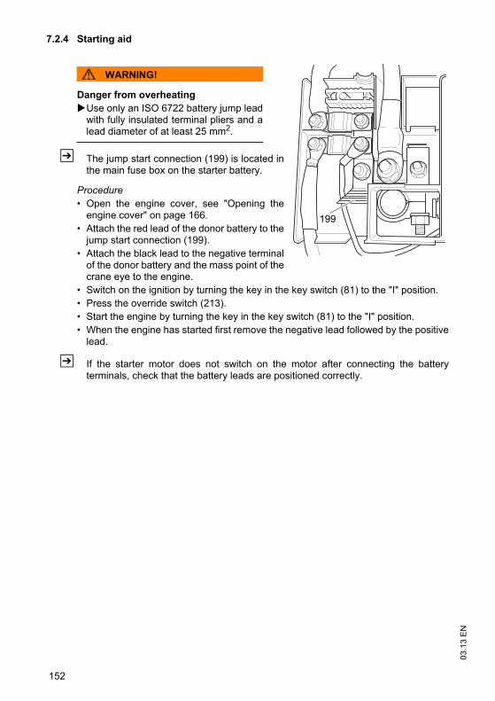
03.1
3 E
N
152
7.2.4 Starting aid
WARNING!
Danger from overheatingUse only an ISO 6722 battery jump leadwith fully insulated terminal pliers and alead diameter of at least 25 mm2.
Z The jump start connection (199) is located inthe main fuse box on the starter battery.
Procedure• Open the engine cover, see "Opening the
engine cover" on page 166. • Attach the red lead of the donor battery to the
jump start connection (199). • Attach the black lead to the negative terminal
of the donor battery and the mass point of thecrane eye to the engine.
• Switch on the ignition by turning the key in the key switch (81) to the "I" position. • Press the override switch (213). • Start the engine by turning the key in the key switch (81) to the "I" position.• When the engine has started first remove the negative lead followed by the positive
lead.
Z If the starter motor does not switch on the motor after connecting the batteryterminals, check that the battery leads are positioned correctly.
199
153
03.1
3 E
NF Industrial Truck Maintenance1 Operational Safety and Environmental Protection
The checks and servicing operations contained in this chapter must be performed inaccordance with the maintenance checklist service intervals.
WARNING!
Risk of accidents and damage to componentsAny modification to the truck, in particular the safety mechanisms, is prohibited. Donot alter the truck's operating speeds under any circumstances.Do not bond the front window with adhesive.
Exception: Owners should only make changes or have changes made to poweredindustrial trucks if the truck manufacturer is no longer operating in the field and thereis no successor to the business; owners must however:– Ensure that the changes to be made are planned, tested and performed by a
specialist engineer in industrial trucks taking safety into account.– keep permanent graphic records of the plans, tests and completion of the changes– carry out and have authorised the respective changes to the capacity data plates,
decals and stickers as well as the operator and service manuals.– attach permanent and clearly visible marking to the truck indicating the types of
changes made, the date of the changes and the name and address of theorganisation responsible for the work.
NOTE
Only original spare parts are subject to the manufacturer's quality control. To ensuresafe and reliable operation, use only the manufacturer's spare parts.For safety reasons, only components which have been specially agreed by themanufacturer for this truck may be installed near the computer, controllers and wireguidance sensors (antennae). These components (computers, controllers, wireguidance sensors (antennae)) must therefore not be replaced by similar componentsfrom other trucks of the same series.
Z On completion of inspection and service work, carry out the operations listed in the“Recommissioning the truck after cleaning or maintenance work” section (see"Restoring the truck to service after maintenance and repairs" on page 198).
03.1
3 E
N
154
2 Maintenance Safety Regulations
Maintenance and repair personnelZ The manufacturer has a service department specially trained for these tasks. A
maintenance contract with the manufacturer will ensure trouble-free operation.
Truck maintenance and repair work must only be carried out by specially trainedpersonnel. The following operations are assigned to the following target groups.
Customer Services
Customer Services are specially trained in the use of the truck and are able to carryout maintenance and repairs independently. Customer Services are aware of therelevant standards, guidelines and safety regulations as well as potential risks.
Operating company
The maintenance personal of the operating company has the technical expertise andexperience to perform the activities in the maintenance check list for the operatingcompany. The maintenance and repair work to be performed by the operatingcompany are also written down, see "Maintenance and repairs" on page 163.
155
03.1
3 E
N
2.1 Working on the electrical system
CAUTION!
Accident risk from Working on the electrical system:Make sure the electrical system is voltage-free before starting work on it.
Remove any rings or metal bracelets etc. before working on electrical components.Only trained personnel may work on the electrical system.Switch off the truck securely (see "Parking the truck securely" on page 79).Before working on the electrical system, all precautionary measures must be takento avoid electrical accidents.Remove the starter battery connecting leads to de-energise the truck.
2.2 Consumables and used parts
CAUTION!
Consumables and used parts are an environmental hazardUsed parts and consumables must be disposed of in accordance with the applicableenvironmental protection regulations. To change the oil contact the manufacturer'scustomer service department, who have been specially trained for this task.
Note the safety regulations when handling these materials.
2.3 Wheels
WARNING!
The use of tyres that do not match the manufacturer's specifications can resultin accidents.The quality of tyres affects the stability and performance of the truck. Uneven wear affects the truck's stability and increases the stopping distance.
When replacing tyres make sure the truck is not skewed.Always replace tyres in pairs, i.e. left and right at the same time.
Z When replacing rims and tyres fitted at the factory, only use the manufacturer’soriginal spare parts. Otherwise the manufacturer’s specifications cannot beensured.
03.1
3 E
N
156
2.4 Lift Chains
WARNING!
Non-lubricated and incorrectly cleaned lift chains can cause accidentsLift chains are safety-critical parts. They must not contain any serious contamination.Lift chains and pivot pins must always be clean and well lubricated.
Lift chains should only be cleaned with paraffin derivatives e.g. petroleum or dieselfuels.Do not clean lift chains with high pressure jets or chemical cleaning agents.Immediately after cleaning, dry the lift chain with compressed air and apply a chainspray.Always lubricate a chain when it is discharged.Lubricate a lift chain with particular care around the pulleys.
WARNING!
Diesel fuel can be hazardousDiesel fuel can cause irritation if it comes into contact with the skin. Rinse anyaffected areas thoroughly. If it comes into contact with the eyes rinse them immediately with flowing water andcall for a doctor.Wear safety gloves when handling diesel fuels.
2.5 Hydraulic system
WARNING!
Brittle hydraulic hose lines can cause accidentsThe hoses must be replaced every six years. The manufacturer's customer servicedepartment is specially trained to carry out these operations.
Observe the date of manufacturer on the hydraulic hoses.
WARNING!
Leaky hydraulic systems can result in accidentsHydraulic oil can escape from leaky and faulty hydraulic systems.
Report any defects immediately to your supervisor.Mark defective truck and take out of service.Do not return the industrial truck to service until you have identified and rectified thefault.Remove any spilled hydraulic immediately with an appropriate bonding agent.The bonding agent / consumable mixture must be disposed of in accordance withregulations.
157
03.1
3 E
NWARNING!
Holes or hairline cracks in the hydraulic hoses can cause injury and infectionPressurised hydraulic oil permeating through fine holes or hairline cracks in thehydraulic hoses can penetrate the skin, causing severe injury.
Call for a doctor immediately if you are injured.Do not touch pressurised hydraulic hoses. Report any defects immediately to your supervisor.Mark defective truck and take out of service.Do not return the industrial truck to service until you have identified and rectified thefault.Remove any spilled hydraulic immediately with an appropriate bonding agent.The bonding agent / consumable mixture must be disposed of in accordance withregulations.
2.6 Working in the vicinity of the engine
WARNING!
Danger from hot fluids and componentsConsumables (hydraulic oil, engine oil, coolant) and power train components(engine, manifold, exhaust system, turbo charger etc.) get very hot duringoperation.When carrying out maintenance and repairs wear suitable protective clothing(gloves etc.) to avoid getting burned.
03.1
3 E
N
158
3 Lubricants and Lubrication Schedule
3.1 Handling consumables safelyHandling consumablesConsumables must always be handled correctly. Follow the manufacturer’sinstructions.
WARNING!
Improper handling is hazardous to health, life and the environmentConsumables can be flammable.
Keep consumables away from hot components and naked flames.Always keep consumables in prescribed containers.Always fill consumables in clean containers.Do not mix up different grades of consumable. The only exception to this is whenmixing is expressly stipulated in the operating instructions.
CAUTION!
Spilled consumables can cause slipping and endanger the environmentRisk of slipping from spilled consumables. The risk is greater when combined withwater.
Do not spill consumables.Spilled consumables must be removed immediately with an appropriate bondingagent.The bonding agent / consumable mixture must be disposed of in accordance withregulations.
159
03.1
3 E
NWARNING!
Improper handling of oils can be hazardousOils (chain spray / hydraulic oil) are flammable and poisonous.
Dispose of used oils in accordance with regulations. Store used oil safely until it canbe disposed of in accordance with regulations.Do not spill oil.Spilled oils must be removed immediately with an appropriate bonding agent.The mixture consisting of the bonding agent and oil must be disposed of inaccordance with regulations.Observe national regulations when handling oils.Wear safety gloves when handling oils.Prevent oil from coming into contact with hot motor parts.Do not smoke when handling oil.Avoid contact and digestion. If you swallow oil do not induce vomiting but seekmedical assistance immediately.Seek fresh air after breathing in oil fumes or vapours.If oil has come into contact with your skin, rinse your skin with water.If oil has come into contact with your eyes, rinse them with water and seek medicalassistance immediately.Replace oil-soaked clothing and shoes immediately.
CAUTION!
Consumables and used parts are an environmental hazardUsed parts and consumables must be disposed of in accordance with the applicableenvironmental protection regulations. To change the oil contact the manufacturer'scustomer service department, who have been specially trained for this task.
Note the safety regulations when handling these materials.
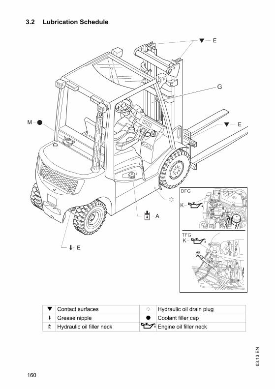
03.1
3 E
N
160
3.2 Lubrication Schedule
g Contact surfaces c Hydraulic oil drain plugs Grease nipple t Coolant filler capS Hydraulic oil filler neck Ö Engine oil filler neck
DFG
TFGK
K
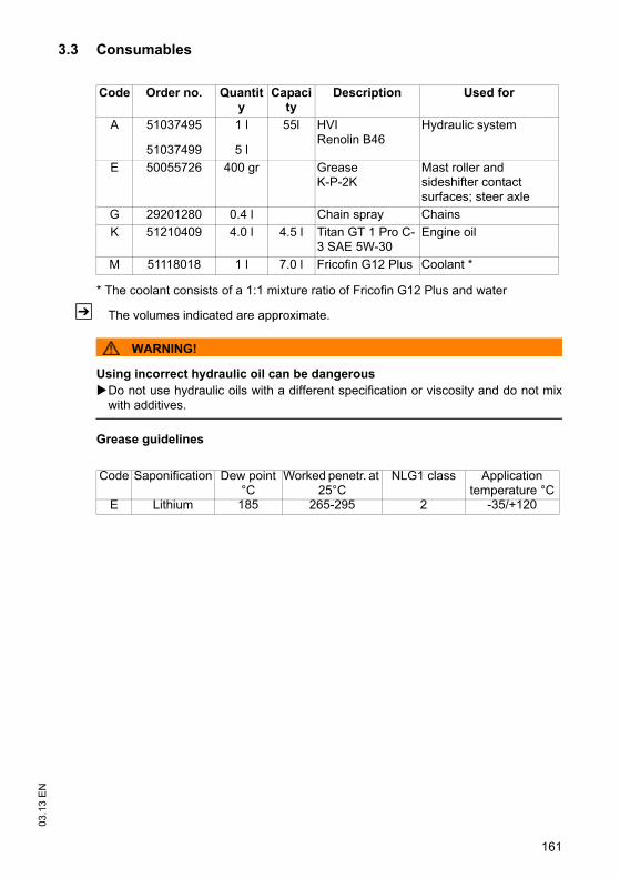
161
03.1
3 E
N3.3 Consumables
* The coolant consists of a 1:1 mixture ratio of Fricofin G12 Plus and water
Z The volumes indicated are approximate.
WARNING!
Using incorrect hydraulic oil can be dangerousDo not use hydraulic oils with a different specification or viscosity and do not mixwith additives.
Grease guidelines
Code Order no. Quantity
Capacity
Description Used for
A 51037495
51037499
1 l
5 l
55l HVI Renolin B46
Hydraulic system
E 50055726 400 gr Grease K-P-2K
Mast roller and sideshifter contact surfaces; steer axle
G 29201280 0.4 l Chain spray ChainsK 51210409 4.0 l 4.5 l Titan GT 1 Pro C-
3 SAE 5W-30Engine oil
M 51118018 1 l 7.0 l Fricofin G12 Plus Coolant *
Code Saponification Dew point °C
Worked penetr. at 25°C
NLG1 class Application temperature °C
E Lithium 185 265-295 2 -35/+120
03.1
3 E
N
162
Coolant specificationThe quality of the coolant used can have a major impact on the efficiency and servicelife of the cooling circuit. The recommendations listed below are useful for servicing agood cooling circuit with anti-freeze and/or anti-corrosion.
Z Always use clean, soft water.
DANGER!
Anti-freeze is poisonousAnti-freeze contains ethylene glycol and other components which can result inpoisoning if ingested. Ingression into the human body can also result if poisonous quantities come intocontact with the skin for long or repeated periods.Note the manufacturer’s safety instructions.
The quality of the anti-freeze must be checked at least annually, e.g. at the start of thecold season.
If the correct procedures are not applied, the manufacturer cannot be held liable forfrost or corrosion damage.
NOTE
Corrosion damageEven if the coolant cannot freeze up due to the application conditions, you must stilluse anti-freeze. The anti-freeze provides protection against corrosion and raises theboiling point of the coolant.
NOTE
Anti-freeze/water mixture ratio:1: 1 (anti-freeze to -35°C)Never mix different types of anti-freeze.
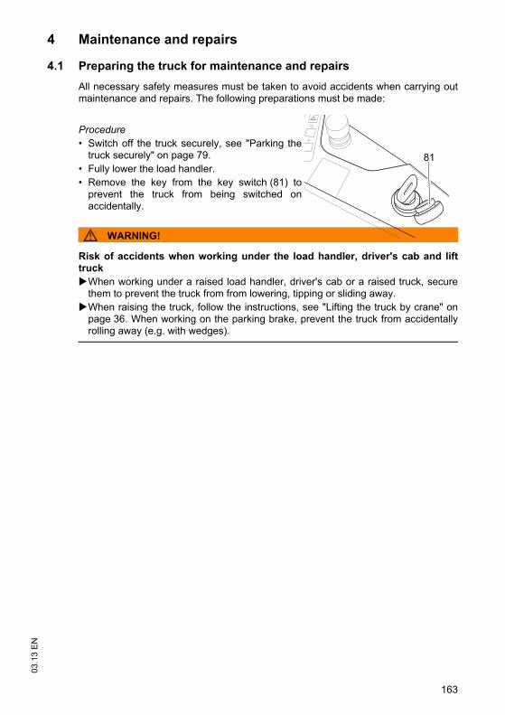
163
03.1
3 E
N4 Maintenance and repairs
4.1 Preparing the truck for maintenance and repairsAll necessary safety measures must be taken to avoid accidents when carrying outmaintenance and repairs. The following preparations must be made:
Procedure• Switch off the truck securely, see "Parking the
truck securely" on page 79.• Fully lower the load handler.• Remove the key from the key switch (81) to
prevent the truck from being switched onaccidentally.
WARNING!
Risk of accidents when working under the load handler, driver's cab and lifttruck
When working under a raised load handler, driver's cab or a raised truck, securethem to prevent the truck from from lowering, tipping or sliding away.When raising the truck, follow the instructions, see "Lifting the truck by crane" onpage 36. When working on the parking brake, prevent the truck from accidentallyrolling away (e.g. with wedges).
81
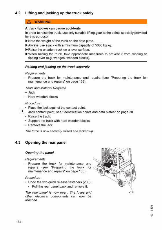
03.1
3 E
N
164
4.2 Lifting and jacking up the truck safely
WARNING!
A truck tipover can cause accidentsIn order to raise the truck, use only suitable lifting gear at the points specially providedfor this purpose.
Note the weight of the truck on the data plate.Always use a jack with a minimum capacity of 5000 kg kg.Raise the unladen truck on a level surface.When raising the truck, take appropriate measures to prevent it from slipping ortipping over (e.g. wedges, wooden blocks).
Raising and jacking up the truck securely
Requirements– Prepare the truck for maintenance and repairs (see "Preparing the truck for
maintenance and repairs" on page 163).
Tools and Material Required– Jack– Hard wooden blocks
Procedure• Place the jack against the contact point.
Z Jack contact point, see "Identification points and data plates" on page 30.• Raise the truck.• Support the truck with hard wooden blocks.• Remove the jack.
The truck is now securely raised and jacked up.
4.3 Opening the rear panel
Opening the panel
Requirements– Prepare the truck for maintenance and
repairs (see "Preparing the truck formaintenance and repairs" on page 163).
Procedure• Undo the two quick release fasteners (200).
• Pull the rear panel back and remove it.
The rear panel is now open. The fuses andother electrical components can now bereached.
200
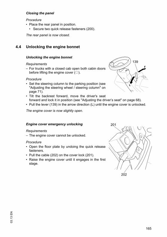
165
03.1
3 E
NClosing the panel
Procedure• Place the rear panel in position.
• Secure two quick release fasteners (200).
The rear panel is now closed.
4.4 Unlocking the engine bonnet
Unlocking the engine bonnet
Requirements– For trucks with a closed cab open both cabin doors
before lifting the engine cover (o).
Procedure• Set the steering column to the parking position (see
"Adjusting the steering wheel / steering column" onpage 71).
• Tilt the backrest forward, move the driver's seatforward and lock it in position (see "Adjusting the driver’s seat" on page 68).
• Pull the lever (139) in the arrow direction (L) until the engine cover is unlocked.
The engine cover is now slightly open.
Engine cover emergency unlocking
Requirements– The engine cover cannot be unlocked.
Procedure• Open the floor plate by undoing the quick release
fasteners.• Pull the cable (202) on the cover lock (201). • Raise the engine cover until it engages in the first
stage.
L
F
139
202
201
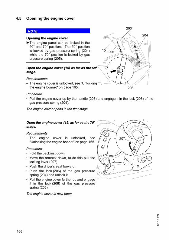
03.1
3 E
N
166
4.5 Opening the engine cover
NOTE
Opening the engine coverThe engine panel can be locked in the50° and 70° positions. The 50° positionis locked by gas pressure spring (204)while the 70° position is locked by gaspressure spring (205).
Open the engine cover (15) as far as the 50°stage.
Requirements– The engine cover is unlocked, see "Unlocking
the engine bonnet" on page 165.
Procedure• Pull the engine cover up by the handle (203) and engage it in the lock (206) of the
gas pressure spring (204).
The engine cover opens in the first stage.
Open the engine cover (15) as far as the 70°stage.
Requirements– The engine cover is unlocked, see
"Unlocking the engine bonnet" on page 165.
Procedure• Fold the backrest down.• Move the armrest down, to do this pull the
locking lever (207).• Push the driver’s seat forward.• Push the lock (206) of the gas pressure
spring (204) and unlock it.• Pull the engine cover further up and engage
it in the lock (206) of the gas pressurespring (205).
The engine cover is now open.
15 205
204
206
203
207
167
03.1
3 E
N
Closing the engine cover
Procedure• Raise the engine cover (15) slightly and hold it in place.• From the 70° stage push in the red lock (206) of the right hand gas pressure spring.
The engine cover is unlocked. • Lower the engine cover as far as the 50° stage.• Raise the engine cover again slightly.• From the 50° stage push in the red lock (206) of the left hand gas pressure spring. • Close the engine cover and make sure it is locked correctly.• Move the backrest back, move the armrest up, push back and lock the driver’s seat.• To adjust the seating position and steering wheel position to your requirements, see
"Adjusting the driver’s seat" on page 68.
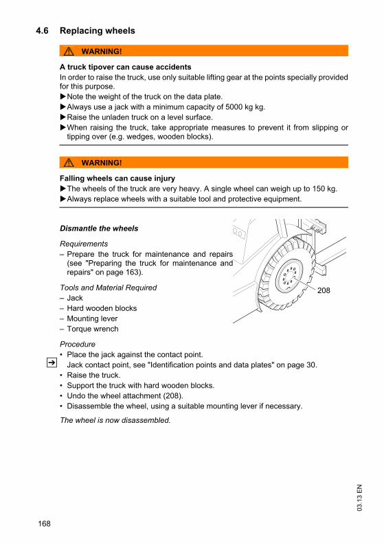
03.1
3 E
N
168
4.6 Replacing wheels
WARNING!
A truck tipover can cause accidentsIn order to raise the truck, use only suitable lifting gear at the points specially providedfor this purpose.
Note the weight of the truck on the data plate.Always use a jack with a minimum capacity of 5000 kg kg.Raise the unladen truck on a level surface.When raising the truck, take appropriate measures to prevent it from slipping ortipping over (e.g. wedges, wooden blocks).
WARNING!
Falling wheels can cause injuryThe wheels of the truck are very heavy. A single wheel can weigh up to 150 kg.Always replace wheels with a suitable tool and protective equipment.
Dismantle the wheels
Requirements– Prepare the truck for maintenance and repairs
(see "Preparing the truck for maintenance andrepairs" on page 163).
Tools and Material Required– Jack– Hard wooden blocks – Mounting lever– Torque wrench
Procedure• Place the jack against the contact point.
Z Jack contact point, see "Identification points and data plates" on page 30.• Raise the truck.• Support the truck with hard wooden blocks.• Undo the wheel attachment (208).• Disassemble the wheel, using a suitable mounting lever if necessary.
The wheel is now disassembled.
208
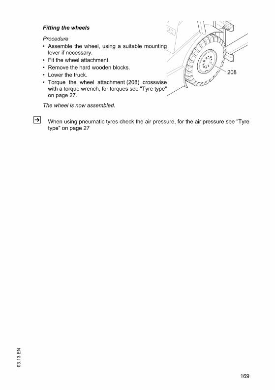
169
03.1
3 E
N
Fitting the wheels
Procedure• Assemble the wheel, using a suitable mounting
lever if necessary.• Fit the wheel attachment.• Remove the hard wooden blocks.• Lower the truck.• Torque the wheel attachment (208) crosswise
with a torque wrench, for torques see "Tyre type"on page 27.
The wheel is now assembled.
Z When using pneumatic tyres check the air pressure, for the air pressure see "Tyretype" on page 27
208
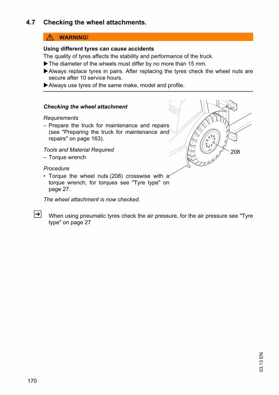
03.1
3 E
N
170
4.7 Checking the wheel attachments.
WARNING!
Using different tyres can cause accidentsThe quality of tyres affects the stability and performance of the truck.
The diameter of the wheels must differ by no more than 15 mm.Always replace tyres in pairs. After replacing the tyres check the wheel nuts aresecure after 10 service hours.Always use tyres of the same make, model and profile.
Checking the wheel attachment
Requirements– Prepare the truck for maintenance and repairs
(see "Preparing the truck for maintenance andrepairs" on page 163).
Tools and Material Required– Torque wrench
Procedure• Torque the wheel nuts (208) crosswise with a
torque wrench, for torques see "Tyre type" onpage 27.
The wheel attachment is now checked.
Z When using pneumatic tyres check the air pressure, for the air pressure see "Tyretype" on page 27
208
171
03.1
3 E
N4.8 Hydraulic system
CAUTION!
The hydraulic oil is pressurised during operation and is a hazard to health and to theenvironment.
Do not touch pressurised hydraulic lines. Dispose of used oil in accordance with regulations. Store used oil safely until it canbe disposed of in accordance with regulations.Do not spill hydraulic oil.Remove any spilled hydraulic immediately with an appropriate bonding agent.The bonding agent / consumable mixture must be disposed of in accordance withregulations.Observe national regulations when handling hydraulic oil.Wear safety gloves when handling hydraulic oil.Prevent hydraulic oil from coming into contact with hot motor parts.Do not smoke when handling hydraulic oil.Avoid contact and digestion. If you swallow oil do not induce vomiting but seekmedical assistance immediately.Seek fresh air after breathing in oil fumes or vapours.If oil has come into contact with your skin, rinse your skin with water.If oil has come into contact with your eyes, rinse them with water and seek medicalassistance immediately.Replace oil-soaked clothing and shoes immediately.
CAUTION!
Consumables and used parts are an environmental hazardUsed parts and consumables must be disposed of in accordance with the applicableenvironmental protection regulations. To change the oil contact the manufacturer'scustomer service department, who have been specially trained for this task.
Note the safety regulations when handling these materials.
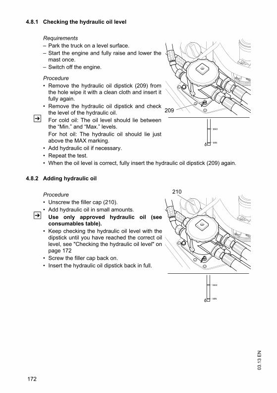
03.1
3 E
N
172
4.8.1 Checking the hydraulic oil level
Requirements– Park the truck on a level surface.– Start the engine and fully raise and lower the
mast once.– Switch off the engine.
Procedure• Remove the hydraulic oil dipstick (209) from
the hole wipe it with a clean cloth and insert itfully again.
• Remove the hydraulic oil dipstick and checkthe level of the hydraulic oil.
Z For cold oil: The oil level should lie betweenthe “Min.” and “Max.” levels.For hot oil: The hydraulic oil should lie justabove the MAX marking.
• Add hydraulic oil if necessary.• Repeat the test.• When the oil level is correct, fully insert the hydraulic oil dipstick (209) again.
4.8.2 Adding hydraulic oil
Procedure• Unscrew the filler cap (210). • Add hydraulic oil in small amounts.
Z Use only approved hydraulic oil (seeconsumables table).
• Keep checking the hydraulic oil level with thedipstick until you have reached the correct oillevel, see "Checking the hydraulic oil level" onpage 172
• Screw the filler cap back on. • Insert the hydraulic oil dipstick back in full.
MIN
MAX
209
MIN
MAX
210
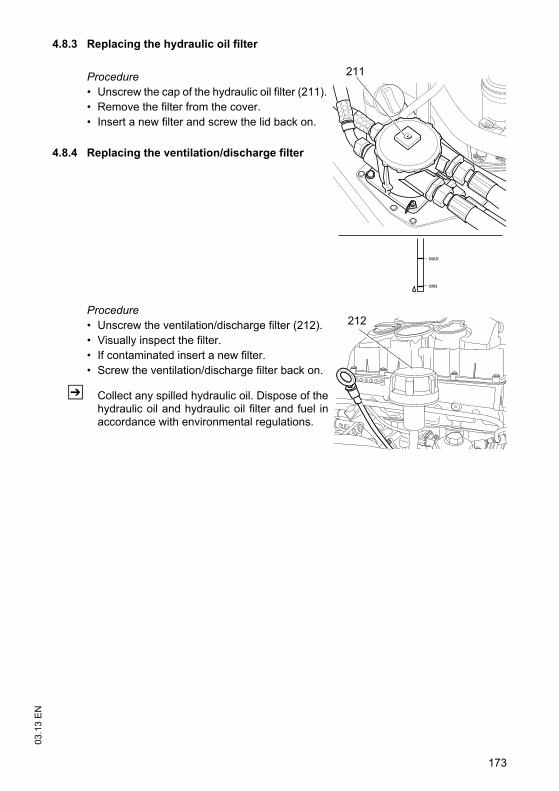
173
03.1
3 E
N4.8.3 Replacing the hydraulic oil filter
Procedure• Unscrew the cap of the hydraulic oil filter (211).• Remove the filter from the cover.• Insert a new filter and screw the lid back on.
4.8.4 Replacing the ventilation/discharge filter
Procedure• Unscrew the ventilation/discharge filter (212).• Visually inspect the filter.• If contaminated insert a new filter.• Screw the ventilation/discharge filter back on.
Z Collect any spilled hydraulic oil. Dispose of thehydraulic oil and hydraulic oil filter and fuel inaccordance with environmental regulations.
MIN
MAX
211
212
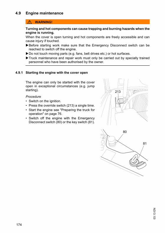
03.1
3 E
N
174
4.9 Engine maintenance
WARNING!
Turning and hot components can cause trapping and burning hazards when theengine is running.When the cover is open turning and hot components are freely accessible and cancause injury if touched.
Before starting work make sure that the Emergency Disconnect switch can bereached to switch off the engine.Do not touch moving parts (e.g. fans, belt drives etc.) or hot surfaces.Truck maintenance and repair work must only be carried out by specially trainedpersonnel who have been authorised by the owner.
4.9.1 Starting the engine with the cover open
The engine can only be started with the coveropen in exceptional circumstances (e.g. jumpstarting).
Procedure• Switch on the ignition.• Press the override switch (213) a single time.• Start the engine see "Preparing the truck for
operation" on page 76.• Switch off the engine with the Emergency
Disconnect switch (80) or the key switch (81).
213
80
81
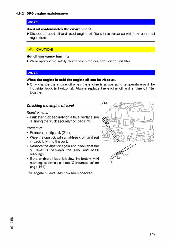
175
03.1
3 E
N4.9.2 DFG engine maintenance
NOTE
Used oil contaminates the environmentDispose of used oil and used engine oil filters in accordance with environmentalregulations.
CAUTION!
Hot oil can cause burning.Wear appropriate safety gloves when replacing the oil and oil filter.
NOTE
When the engine is cold the engine oil can be viscous.Only change the engine oil when the engine is at operating temperature and theindustrial truck is horizontal. Always replace the engine oil and engine oil filtertogether.
Checking the engine oil level
Requirements– Park the truck securely on a level surface see
"Parking the truck securely" on page 79.
Procedure• Remove the dipstick (214).• Wipe the dipstick with a lint-free cloth and put
in back fully into the port.• Remove the dipstick again and check that the
oil level is between the MIN and MAXmarkings.
• If the engine oil level is below the bottom MINmarking, add more oil (see "Consumables" onpage 161).
The engine oil level has now been checked.
MIN
MAX
214
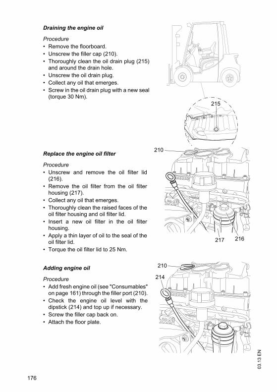
03.1
3 E
N
176
Draining the engine oil
Procedure• Remove the floorboard.• Unscrew the filler cap (210).• Thoroughly clean the oil drain plug (215)
and around the drain hole.• Unscrew the oil drain plug.• Collect any oil that emerges.• Screw in the oil drain plug with a new seal
(torque 30 Nm).
Replace the engine oil filter
Procedure• Unscrew and remove the oil filter lid
(216).• Remove the oil filter from the oil filter
housing (217).• Collect any oil that emerges.• Thoroughly clean the raised faces of the
oil filter housing and oil filter lid.• Insert a new oil filter in the oil filter
housing.• Apply a thin layer of oil to the seal of the
oil filter lid.• Torque the oil filter lid to 25 Nm.
Adding engine oil
Procedure• Add fresh engine oil (see "Consumables"
on page 161) through the filler port (210).• Check the engine oil level with the
dipstick (214) and top up if necessary.• Screw the filler cap back on.• Attach the floor plate.
215
210
216217
210
214
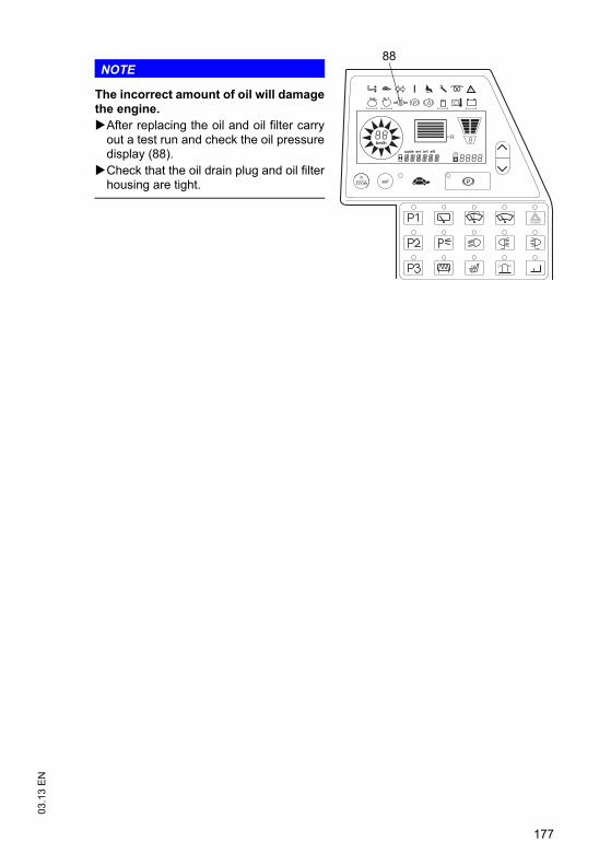
177
03.1
3 E
N
NOTE
The incorrect amount of oil will damagethe engine.
After replacing the oil and oil filter carryout a test run and check the oil pressuredisplay (88).Check that the oil drain plug and oil filterhousing are tight.
km/h
R
88
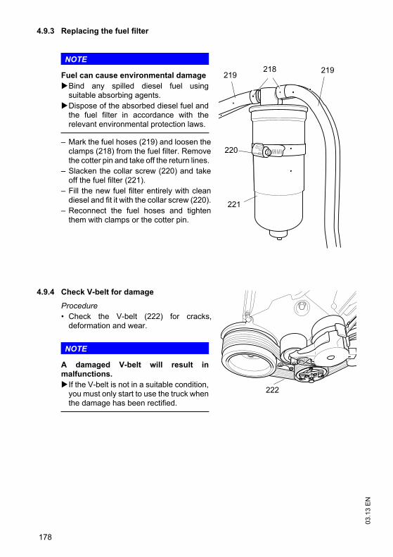
03.1
3 E
N
178
4.9.3 Replacing the fuel filter
NOTE
Fuel can cause environmental damageBind any spilled diesel fuel usingsuitable absorbing agents.Dispose of the absorbed diesel fuel andthe fuel filter in accordance with therelevant environmental protection laws.
– Mark the fuel hoses (219) and loosen theclamps (218) from the fuel filter. Removethe cotter pin and take off the return lines.
– Slacken the collar screw (220) and takeoff the fuel filter (221).
– Fill the new fuel filter entirely with cleandiesel and fit it with the collar screw (220).
– Reconnect the fuel hoses and tightenthem with clamps or the cotter pin.
4.9.4 Check V-belt for damage
Procedure• Check the V-belt (222) for cracks,
deformation and wear.
NOTE
A damaged V-belt will result inmalfunctions.
If the V-belt is not in a suitable condition,you must only start to use the truck whenthe damage has been rectified.
219218219
220
221
222
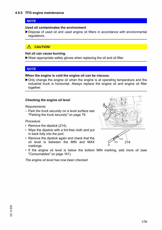
179
03.1
3 E
N4.9.5 TFG engine maintenance
NOTE
Used oil contaminates the environmentDispose of used oil and used engine oil filters in accordance with environmentalregulations.
CAUTION!
Hot oil can cause burning.Wear appropriate safety gloves when replacing the oil and oil filter
NOTE
When the engine is cold the engine oil can be viscous.Only change the engine oil when the engine is at operating temperature and theindustrial truck is horizontal. Always replace the engine oil and engine oil filtertogether.
Checking the engine oil level
Requirements– Park the truck securely on a level surface see
"Parking the truck securely" on page 79.
Procedure• Remove the dipstick (214).• Wipe the dipstick with a lint-free cloth and put
in back fully into the port.• Remove the dipstick again and check that the
oil level is between the MIN and MAXmarkings.
• If the engine oil level is below the bottom MIN marking, add more oil (see"Consumables" on page 161).
The engine oil level has now been checked.
MIN
MAX
214
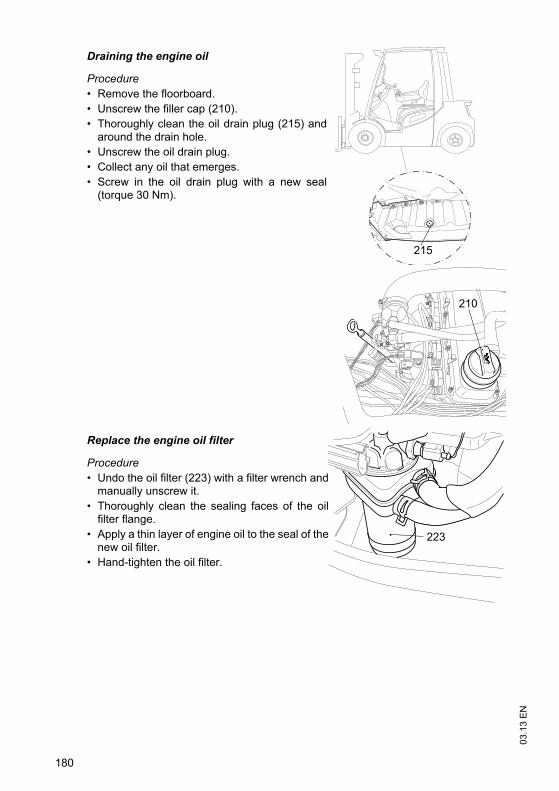
03.1
3 E
N
180
Draining the engine oil
Procedure• Remove the floorboard.• Unscrew the filler cap (210).• Thoroughly clean the oil drain plug (215) and
around the drain hole.• Unscrew the oil drain plug.• Collect any oil that emerges.• Screw in the oil drain plug with a new seal
(torque 30 Nm).
Replace the engine oil filter
Procedure• Undo the oil filter (223) with a filter wrench and
manually unscrew it.• Thoroughly clean the sealing faces of the oil
filter flange.• Apply a thin layer of engine oil to the seal of the
new oil filter.• Hand-tighten the oil filter.
215
210
223
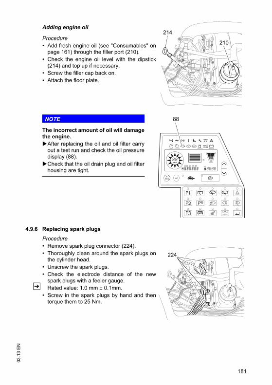
181
03.1
3 E
N
Adding engine oil
Procedure• Add fresh engine oil (see "Consumables" on
page 161) through the filler port (210).• Check the engine oil level with the dipstick
(214) and top up if necessary.• Screw the filler cap back on.• Attach the floor plate.
NOTE
The incorrect amount of oil will damagethe engine.
After replacing the oil and oil filter carryout a test run and check the oil pressuredisplay (88).Check that the oil drain plug and oil filterhousing are tight.
4.9.6 Replacing spark plugs
Procedure• Remove spark plug connector (224).• Thoroughly clean around the spark plugs on
the cylinder head.• Unscrew the spark plugs.• Check the electrode distance of the new
spark plugs with a feeler gauge. Z Rated value: 1.0 mm ± 0.1mm.
• Screw in the spark plugs by hand and thentorque them to 25 Nm.
210
214
km/h
R
88
224
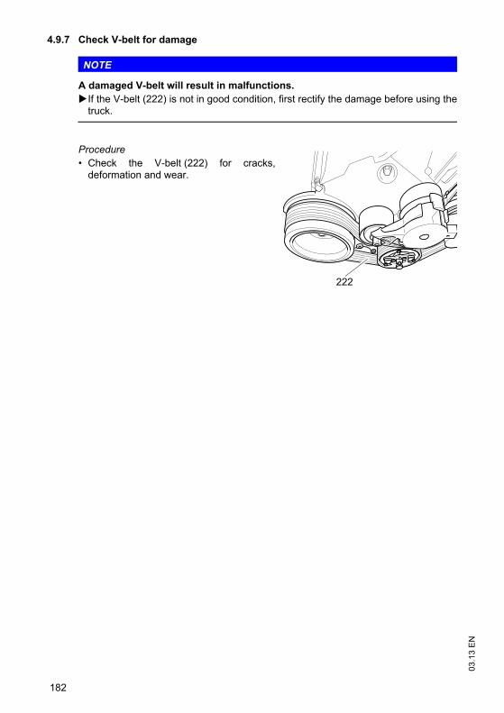
03.1
3 E
N
182
4.9.7 Check V-belt for damage
NOTE
A damaged V-belt will result in malfunctions.If the V-belt (222) is not in good condition, first rectify the damage before using thetruck.
Procedure• Check the V-belt (222) for cracks,
deformation and wear.
222
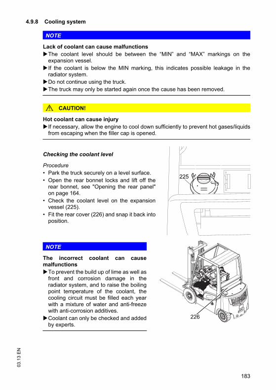
183
03.1
3 E
N4.9.8 Cooling system
NOTE
Lack of coolant can cause malfunctionsThe coolant level should be between the “MIN” and “MAX” markings on theexpansion vessel.If the coolant is below the MIN marking, this indicates possible leakage in theradiator system.Do not continue using the truck.The truck may only be started again once the cause has been removed.
CAUTION!
Hot coolant can cause injuryIf necessary, allow the engine to cool down sufficiently to prevent hot gases/liquidsfrom escaping when the filler cap is opened.
Checking the coolant level
Procedure• Park the truck securely on a level surface.• Open the rear bonnet locks and lift off the
rear bonnet, see "Opening the rear panel"on page 164.
• Check the coolant level on the expansionvessel (225).
• Fit the rear cover (226) and snap it back intoposition.
NOTE
The incorrect coolant can causemalfunctions
To prevent the build up of lime as well asfront and corrosion damage in theradiator system, and to raise the boilingpoint temperature of the coolant, thecooling circuit must be filled each yearwith a mixture of water and anti-freezewith anti-corrosion additives.Coolant can only be checked and addedby experts.
225
226
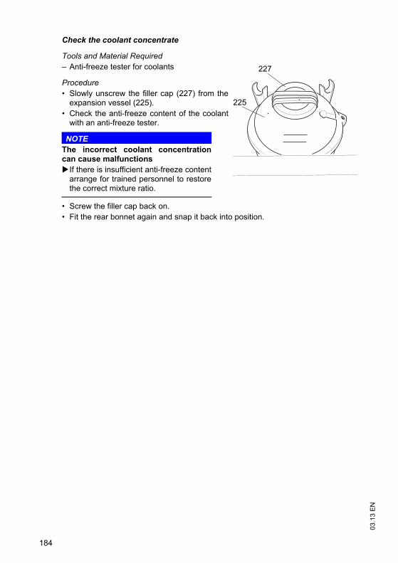
03.1
3 E
N
184
Check the coolant concentrate
Tools and Material Required– Anti-freeze tester for coolants
Procedure• Slowly unscrew the filler cap (227) from the
expansion vessel (225).• Check the anti-freeze content of the coolant
with an anti-freeze tester.
NOTEThe incorrect coolant concentrationcan cause malfunctions
If there is insufficient anti-freeze contentarrange for trained personnel to restorethe correct mixture ratio.
• Screw the filler cap back on.• Fit the rear bonnet again and snap it back into position.
227
225
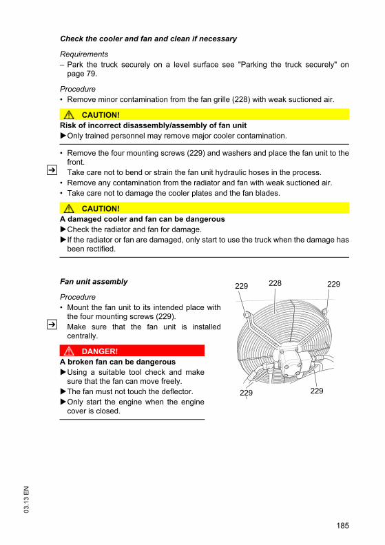
185
03.1
3 E
N
Check the cooler and fan and clean if necessary
Requirements– Park the truck securely on a level surface see "Parking the truck securely" on
page 79.
Procedure• Remove minor contamination from the fan grille (228) with weak suctioned air.
CAUTION!Risk of incorrect disassembly/assembly of fan unit
Only trained personnel may remove major cooler contamination.
• Remove the four mounting screws (229) and washers and place the fan unit to thefront.
Z Take care not to bend or strain the fan unit hydraulic hoses in the process.• Remove any contamination from the radiator and fan with weak suctioned air.• Take care not to damage the cooler plates and the fan blades.
CAUTION!A damaged cooler and fan can be dangerous
Check the radiator and fan for damage.If the radiator or fan are damaged, only start to use the truck when the damage hasbeen rectified.
Fan unit assembly
Procedure• Mount the fan unit to its intended place with
the four mounting screws (229).Z Make sure that the fan unit is installed
centrally.
DANGER!A broken fan can be dangerous
Using a suitable tool check and makesure that the fan can move freely.The fan must not touch the deflector.Only start the engine when the enginecover is closed.
228 229229
229 229
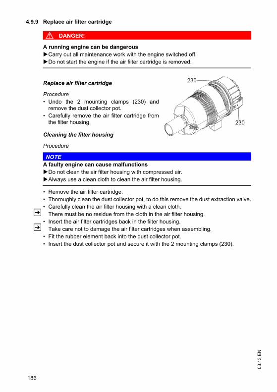
03.1
3 E
N
186
4.9.9 Replace air filter cartridge
DANGER!
A running engine can be dangerousCarry out all maintenance work with the engine switched off. Do not start the engine if the air filter cartridge is removed.
Replace air filter cartridge
Procedure• Undo the 2 mounting clamps (230) and
remove the dust collector pot. • Carefully remove the air filter cartridge from
the filter housing.
Cleaning the filter housing
Procedure
NOTEA faulty engine can cause malfunctions
Do not clean the air filter housing with compressed air.Always use a clean cloth to clean the air filter housing.
• Remove the air filter cartridge.• Thoroughly clean the dust collector pot, to do this remove the dust extraction valve.• Carefully clean the air filter housing with a clean cloth.
Z There must be no residue from the cloth in the air filter housing.• Insert the air filter cartridges back in the filter housing.
Z Take care not to damage the air filter cartridges when assembling. • Fit the rubber element back into the dust collector pot.• Insert the dust collector pot and secure it with the 2 mounting clamps (230).
230
230
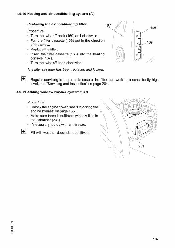
187
03.1
3 E
N4.9.10 Heating and air conditioning system (o)
Replacing the air conditioning filter
Procedure• Turn the twist off knob (169) anti-clockwise. • Pull the filter cassette (168) out in the direction
of the arrow.• Replace the filter.• Insert the filter cassette (168) into the heating
console (167).• Turn the twist-off knob clockwise
The filter cassette has been replaced and locked.
Z Regular servicing is required to ensure the filter can work at a consistently highlevel, see "Servicing and Inspection" on page 204.
4.9.11 Adding window washer system fluid
Procedure• Unlock the engine cover, see "Unlocking the
engine bonnet" on page 165.• Make sure there is sufficient window fluid in
the container (231).• If necessary top up with anti-freeze.
Z Fill with weather-dependent additives.
167168
169
231
o
03.1
3 E
N
188
4.10 Checking electrical fusesChecking electrical fuses
Requirements– Prepare the truck for maintenance and repairs (see "Preparing the truck for
maintenance and repairs" on page 163).
Procedure• Open the rear cover of the truck, see "Opening the rear panel" on page 164.• Remove the electrical system cap.• Check condition and rating of the fuses in accordance with the table.
• To do this: Insert the fuse to be check in the fuse socket (53 F21).• If the fuse is intact the LED will be lit.
• Replace any damaged fuses in accordance with the table.• Close the electrical system cap. • Close the rear cover of the truck.
The electrical fuses are now checked.
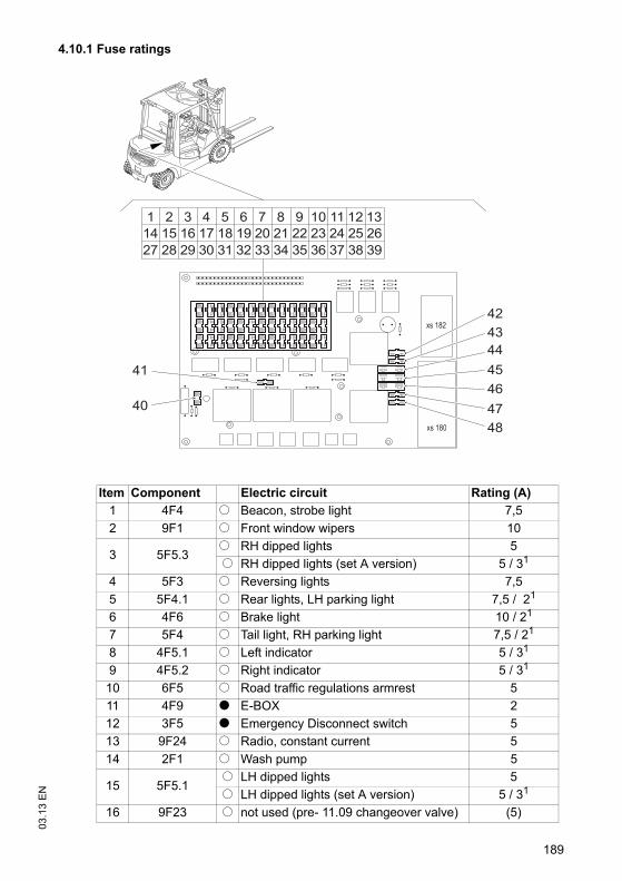
189
03.1
3 E
N4.10.1 Fuse ratings
Item Component Electric circuit Rating (A)1 4F4 o Beacon, strobe light 7,52 9F1 o Front window wipers 10
3 5F5.3o RH dipped lights 5 o RH dipped lights (set A version) 5 / 31
4 5F3 o Reversing lights 7,55 5F4.1 o Rear lights, LH parking light 7,5 / 21
6 4F6 o Brake light 10 / 21
7 5F4 o Tail light, RH parking light 7,5 / 21
8 4F5.1 o Left indicator 5 / 31
9 4F5.2 o Right indicator 5 / 31
10 6F5 o Road traffic regulations armrest 511 4F9 t E-BOX 212 3F5 t Emergency Disconnect switch 513 9F24 o Radio, constant current 514 2F1 o Wash pump 5
15 5F5.1o LH dipped lights 5o LH dipped lights (set A version) 5 / 31
16 9F23 o not used (pre- 11.09 changeover valve) (5)
xs 182
xs 180
1 2 3 4 5 6 7 8 9 10 11 12 1314 15 16 17 18 19 20 21 22 23 24 25 2627 28 29 30 31 32 33 34 35 36 37 38 39
42
40
41
434445464748
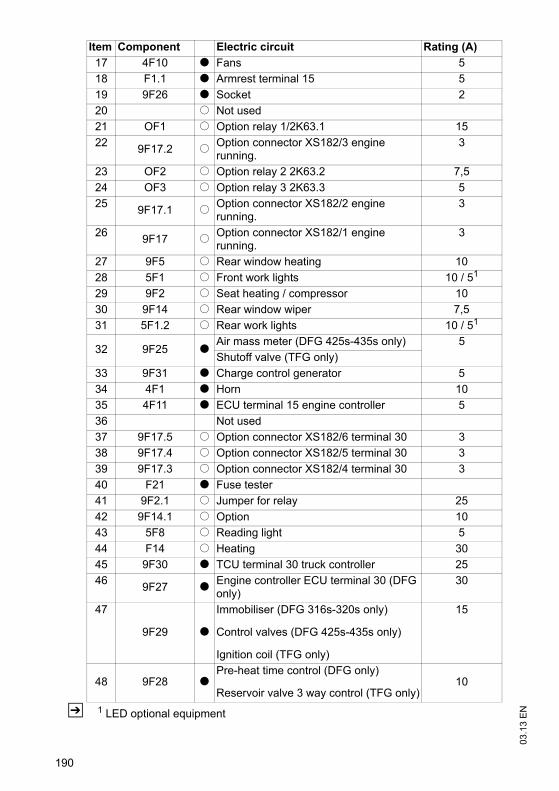
03.1
3 E
N
190
Z 1 LED optional equipment
17 4F10 t Fans 518 F1.1 t Armrest terminal 15 519 9F26 t Socket 220 o Not used21 OF1 o Option relay 1/2K63.1 1522 9F17.2 o Option connector XS182/3 engine
running.3
23 OF2 o Option relay 2 2K63.2 7,524 OF3 o Option relay 3 2K63.3 525 9F17.1 o Option connector XS182/2 engine
running.3
26 9F17 o Option connector XS182/1 engine running.
3
27 9F5 o Rear window heating 1028 5F1 o Front work lights 10 / 51
29 9F2 o Seat heating / compressor 1030 9F14 o Rear window wiper 7,531 5F1.2 o Rear work lights 10 / 51
32 9F25 tAir mass meter (DFG 425s-435s only) 5Shutoff valve (TFG only)
33 9F31 t Charge control generator 534 4F1 t Horn 1035 4F11 t ECU terminal 15 engine controller 536 Not used37 9F17.5 o Option connector XS182/6 terminal 30 338 9F17.4 o Option connector XS182/5 terminal 30 339 9F17.3 o Option connector XS182/4 terminal 30 340 F21 t Fuse tester41 9F2.1 o Jumper for relay 2542 9F14.1 o Option 1043 5F8 o Reading light 544 F14 o Heating 3045 9F30 t TCU terminal 30 truck controller 2546 9F27 t Engine controller ECU terminal 30 (DFG
only)30
47
9F29 t
Immobiliser (DFG 316s-320s only)
Control valves (DFG 425s-435s only)
Ignition coil (TFG only)
15
48 9F28 tPre-heat time control (DFG only)
Reservoir valve 3 way control (TFG only)10
Item Component Electric circuit Rating (A)

191
03.1
3 E
N
t= Series equipment o= Optional equipment
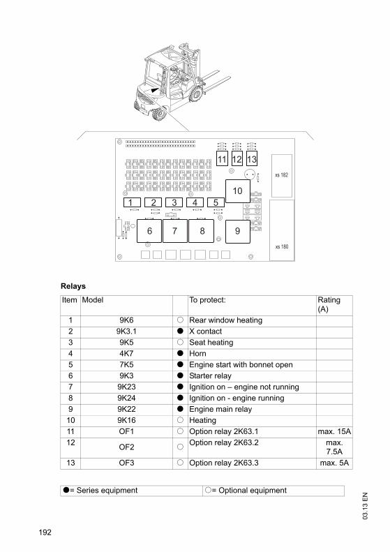
03.1
3 E
N
192
Relays
Item Model To protect: Rating (A)
1 9K6 o Rear window heating2 9K3.1 t X contact3 9K5 o Seat heating4 4K7 t Horn5 7K5 t Engine start with bonnet open6 9K3 t Starter relay7 9K23 t Ignition on – engine not running8 9K24 t Ignition on - engine running 9 9K22 t Engine main relay10 9K16 o Heating11 OF1 o Option relay 2K63.1 max. 15A12 OF2 o Option relay 2K63.2 max.
7.5A13 OF3 o Option relay 2K63.3 max. 5A
t= Series equipment o= Optional equipment
xs 182
xs 180
1 2 3 4 5
6 7 8 9
10
11 12 13
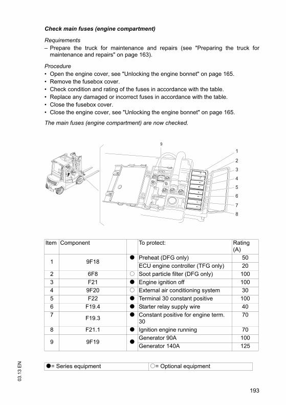
193
03.1
3 E
N
Check main fuses (engine compartment)
Requirements– Prepare the truck for maintenance and repairs (see "Preparing the truck for
maintenance and repairs" on page 163).
Procedure• Open the engine cover, see "Unlocking the engine bonnet" on page 165.• Remove the fusebox cover.• Check condition and rating of the fuses in accordance with the table.• Replace any damaged or incorrect fuses in accordance with the table.• Close the fusebox cover. • Close the engine cover, see "Unlocking the engine bonnet" on page 165.
The main fuses (engine compartment) are now checked.
Item Component To protect: Rating (A)
1 9F18t Preheat (DFG only) 50
ECU engine controller (TFG only) 202 6F8 o Soot particle filter (DFG only) 1003 F21 t Engine ignition off 1004 9F20 o External air conditioning system 305 F22 t Terminal 30 constant positive 1006 F19.4 t Starter relay supply wire 407 F19.3 t Constant positive for engine term.
3070
8 F21.1 t Ignition engine running 70
9 9F19 tGenerator 90A 100Generator 140A 125
t= Series equipment o= Optional equipment
1
2
3
4
5
6
7
8
9
03.1
3 E
N
194
4.11 Cleaning
CAUTION!
Fire hazardThe truck must not be cleaned with flammable fluids.If flammable materials are not removed from the engine compartment, they can comeinto contact with hot components and cause a fire.
Carry out all necessary safety measures to prevent sparking before cleaning (e.g.by short-circuiting).Remove all deposits / accumulations of flammable materials from the enginecompartment.
CAUTION!
Risk of component damage when cleaning the truckCleaning with a pressure washer can result in malfunctions due to humidity.
Cover all electronic system assemblies (controllers, sensors, motors etc.) beforecleaning the truck with a pressure washer.Do not hold the jet of the pressure washer by the marked points to avoid damagingthem (see "Identification points and data plates" on page 30).Do not clean the truck with pressurised water.
Cleaning the truck
Requirements– Prepare the truck for maintenance and repairs (see "Preparing the truck for
maintenance and repairs" on page 163).
Tools and Material Required– Water-based solvents– Sponge or cloth
Procedure• Clean the surface of the truck with water-based solvents and water. Use a sponge
or cloth to clean.• In particular, clean the following areas:
• Windows• All walk-on areas• Oil filler ports and their surroundings• Grease nipples (before lubrication)
• Dry the truck after cleaning, e.g. with compressed air or a dry cloth.• Carry out all the tasks in the section "Recommissioning the truck after cleaning or
maintenance work" (see "Restoring the truck to service after maintenance andrepairs" on page 198).
The truck is now clean.
195
03.1
3 E
NCAUTION!
Risk of electrical system damageCleaning the assemblies (controllers, sensors, motors etc.) of the electronic systemwith water can damage the electrical system.
Do not clean the electrical system with water.Clean the electrical system with weak suction or compressed air (use a compressorwith a water trap) and not a conductive, anti-static brush.
Cleaning the electrical system assemblies
Requirements– Prepare the truck for maintenance and repairs (see "Preparing the truck for
maintenance and repairs" on page 163).
Tools and Material Required– Compressor with water separator– Non-conductive, antistatic brush
Procedure• Expose the electrical system, see "Opening the rear panel" on page 164.• Clean the electrical system assemblies with weak suction or compressed air (use a
compressor with a water trap) and not a conductive, anti-static brush.• Fit the electrical system panel, see "Opening the rear panel" on page 164.• Carry out all the tasks in the section "Recommissioning the truck after cleaning or
maintenance work" (see "Restoring the truck to service after decommissioning" onpage 201).
The electrical system assemblies are now clean.
03.1
3 E
N
196
4.12 Starter batteryChecking the battery condition, acid level* and acid density*
Z *not for maintenance-free batteries
WARNING!
Batteries can be hazardousBatteries contain an acid solution which is poisonous and corrosive. Avoid contactwith battery acid at all times.
Dispose of used battery acid in accordance with regulations.Always wear protective clothing and goggles when working with batteries.Do not let battery acid come into contact with skin, clothing or eyes. If necessary,rinse with plenty of clean water.In the event of physical damage (e.g. skin or eye contact with battery acid) call fora doctor immediately.Spilled battery acid should be neutralised immediately with plenty of water.Only batteries with a sealed battery container may be used.Follow national guidelines and legislation.
Check battery
Procedure• Check the battery housing for cracks and any spilled acid. • Remove any oxidisation remains from the battery terminals.• Lubricate the battery terminals with an acid-free grease.
Checking the acid density
Procedure• Clean the area around the inspection plugs.• Unscrew the drain plug.
Z The acid should lie between the top and bottom markings.• If necessary, add distilled water to the top mark.• Check the acid density with an acid siphon.
Z If the battery is charged sufficiently, the acid density should be 1.24 to 1.28 kg/l.• Screw the inspection plugs back on.• Recharge the battery as required.
Battery disposalBatteries may only be disposed of in accordance with national environmentalprotection regulations or disposal laws. The manufacturer’s disposal instructions mustbe followed.
197
03.1
3 E
N
4.13 Exhaust system
NOTE
Check emissions at regular intervalsCheck the combustion engine exhaust emissions at regular intervals in accordancewith national regulations.Black or blue exhaust smoke is an indicator of high emission levels resulting fromcombustion engine damage or wear.In this case the truck must be examined by specialist personnel.
Check the exhaust system regularly for leaks.
Procedure• Open the engine cover.• Start the engine with the engine cover open see "Starting the engine with the cover
open" on page 174.• Check for any rising smell of exhaust and altered engine noise level.• If you detect a rising smell of exhaust and altered engine noise level arrange for the
exhaust system to be inspected by specialist personnel.
The exhaust system has now been checked for leaks.
03.1
3 E
N
198
4.14 Restoring the truck to service after maintenance and repairsProcedure• Thoroughly clean the truck, see "Cleaning" on page 194.• Lubricate the truck according to the lubrication schedule, see "Lubrication
Schedule" on page 160.• Clean the starter battery, grease the terminals and connect the starter battery.
WARNING!Faulty brakes can cause accidentsAs soon as the truck has been started, test the brakes several times.
Report any defects immediately to your supervisor.Tag out and decommission the faulty industrial truck.Only return the truck to service when you have identified and rectified the fault.
• Start up the truck, see "Preparing the Truck for Operation" on page 65.
199
03.1
3 E
N5 Decommissioning the industrial truck
If the truck is to be out of service for more than a month, it must be stored in a frost-free and dry room. All necessary measures must be taken before, during and afterdecommissioning as described hereafter.
When the truck is out of service it must be jacked up so that all the wheels are clearof the ground. This is the only way of ensuring that the wheels and wheel bearings arenot damaged.
Z Jack up the truck, see "Lifting and jacking up the truck safely" on page 164.
If the truck is to be out of service for more than 6 months, agree further measures withthe manufacturer's customer service department.
03.1
3 E
N
200
5.1 Prior to decommissioningProcedure• Thoroughly clean the truck, see "Cleaning" on page 194.• Prevent the truck from rolling away.• Check the hydraulic oil level and replenish if necessary,
see "Checking the hydraulic oil level" on page 172.• Apply a thin layer of oil or grease to any non-painted mechanical components.• Lubricate the truck according to the lubrication schedule, see "Lubrication
Schedule" on page 160.• Disconnect the battery, clean it and grease the terminals.
Z In addition, follow the battery manufacturer’s instructions.
5.2 During decommissioning
NOTE
Full discharge can damage the batterySelf-discharge can cause the battery to fully discharge. Full discharge shortens theuseful life of the battery.
Charge the battery at least every 2 months.
201
03.1
3 E
N5.3 Restoring the truck to service after decommissioning
Procedure• Thoroughly clean the truck, see "Cleaning" on page 194.• Lubricate the truck according to the lubrication schedule, see "Lubrication
Schedule" on page 160.• Clean the starter battery, grease the terminals and connect the starter battery.• Charge the starter battery, see "Starter battery" on page 196.• Replace engine oil. Condensation water could have formed.• Replace hydraulic oil. Condensation water could have formed.
Z The manufacturer's customer service department is specially trained to carry outthese operations.
• Start up the truck, see "Preparing the Truck for Operation" on page 65.
WARNING!
Faulty brakes can cause accidentsAs soon as the truck has been started, test the brakes several times.
Report any defects immediately to your supervisor.Tag out and decommission the faulty industrial truck.Only return the truck to service when you have identified and rectified the fault.
03.1
3 E
N
202
6 Safety tests to be performed at intervals and after unusual incidents
Z Perform a safety check in accordance with national regulations. The manufacturerrecommends the truck be checked to FEM guideline 4.004. The manufacturer hasa service department specially trained for these tasks.
The truck must be inspected at least annually (refer to national regulations) or afterany unusual event by a qualified inspector. The inspector shall assess the conditionof the system from purely a safety viewpoint, without regard to operational oreconomic circumstances. The inspector must be sufficiently instructed andexperienced to be able to assess the condition of the truck and the effectiveness ofthe safety mechanisms based on the technical regulations and principles governingthe inspection of forklift trucks.
A thorough test of the truck must be undertaken with regard to its technical conditionfrom a safety aspect. The truck must also be examined for damage caused bypossible improper use. A test report shall be produced. The test results must be keptfor at least the next 2 inspections.
The proprietor is responsible for ensuring that faults are immediately rectified.
Z A test plaque is attached to the truck as proof that it has passed the safetyinspection. This plaque indicates the due date for the next inspection.
203
03.1
3 E
N7 Final de-commissioning, disposal
Z Final de-commissioning or disposal of the truck in must be performed in accordancewith the regulations of the country of use. In particular, regulations governing thedisposal of batteries, consumables and electronic and electrical systems must beobserved.
The truck must only be disassembled by trained personnel in accordance with theprocedures as specified by the manufacturer.
8 Human vibration measurement
Z Vibrations that affect the operator over the course of the day are known as humanvibrations. Excessive human vibrations will cause the operator long term healthproblems. The European "2002/44/EC/Vibration" operator directive has thereforebeen established to protect operators. To help operators to assess the applicationsituation, the manufacturer offers a service of measuring these human vibrations.
03.1
3 E
N
204
9 Servicing and Inspection
WARNING!
Risk of accident due to neglected maintenanceFailure to perform regular servicing can lead to truck failure and poses a potentialhazard to personnel and equipment.
Thorough and expert servicing is one of the most important requirements for thesafe operation of the industrial truck.
The application conditions of an industrial truck have a considerable impact oncomponent wear. The following service intervals are based on single-shift operationunder normal operating conditions. They must be reduced accordingly if theequipment is to be used in conditions of extreme dust, temperature fluctuations ormultiple shifts.
NOTE
To prevent damage due to wear, the manufacturer recommends an on-site applicationanalysis to agree on appropriate service intervals.
The following maintenance checklist lists the activities to be performed and therespective intervals to be observed. Maintenance intervals are defined as:
Z "W" maintenance-interval activities should be performed by the operating company.
During the run-in period,after approx. 100 service hours, the owner must check thewheel nuts/bolts and re-tighten if necessary.
W = Every 50 service hours, at least weeklyA = Every 500 service hoursB = Every 1000 service hours, or at least annuallyC = Every 2000 service hours, or at least annuallyt = Standard maintenance interval
k = Cold store maintenance interval (in addition to standard maintenance interval)
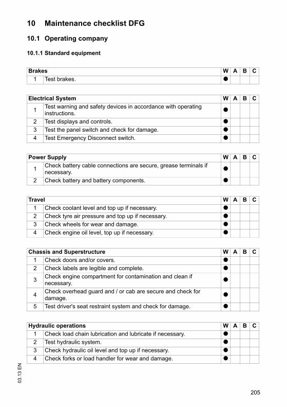
205
03.1
3 E
N10 Maintenance checklist DFG
10.1 Operating company
10.1.1 Standard equipment
Brakes W A B C1 Test brakes. t
Electrical System W A B C
1 Test warning and safety devices in accordance with operating instructions. t
2 Test displays and controls. t3 Test the panel switch and check for damage. t4 Test Emergency Disconnect switch. t
Power Supply W A B C
1 Check battery cable connections are secure, grease terminals if necessary. t
2 Check battery and battery components. t
Travel W A B C1 Check coolant level and top up if necessary. t2 Check tyre air pressure and top up if necessary. t3 Check wheels for wear and damage. t4 Check engine oil level, top up if necessary. t
Chassis and Superstructure W A B C1 Check doors and/or covers. t2 Check labels are legible and complete. t
3 Check engine compartment for contamination and clean if necessary. t
4 Check overhead guard and / or cab are secure and check for damage. t
5 Test driver's seat restraint system and check for damage. t
Hydraulic operations W A B C1 Check load chain lubrication and lubricate if necessary. t2 Test hydraulic system. t3 Check hydraulic oil level and top up if necessary. t4 Check forks or load handler for wear and damage. t
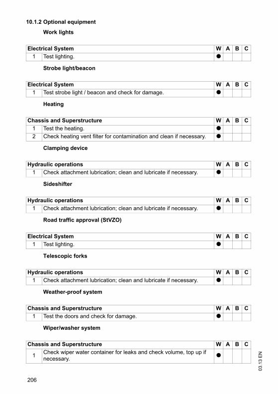
03.1
3 E
N
206
10.1.2 Optional equipment
Work lights
Strobe light/beacon
Heating
Clamping device
Sideshifter
Road traffic approval (StVZO)
Telescopic forks
Weather-proof system
Wiper/washer system
Electrical System W A B C1 Test lighting. t
Electrical System W A B C1 Test strobe light / beacon and check for damage. t
Chassis and Superstructure W A B C1 Test the heating. t2 Check heating vent filter for contamination and clean if necessary. t
Hydraulic operations W A B C1 Check attachment lubrication; clean and lubricate if necessary. t
Hydraulic operations W A B C1 Check attachment lubrication; clean and lubricate if necessary. t
Electrical System W A B C1 Test lighting. t
Hydraulic operations W A B C1 Check attachment lubrication; clean and lubricate if necessary. t
Chassis and Superstructure W A B C1 Test the doors and check for damage. t
Chassis and Superstructure W A B C
1 Check wiper water container for leaks and check volume, top up if necessary. t

207
03.1
3 E
NFork adjuster
Optional equipment
Hydraulic operations W A B C1 Check attachment lubrication; clean and lubricate if necessary. t
Chassis and Superstructure W A B C
1Check that optional equipment such as mirrors, storage compartments, grips, windscreen wipers and washing systems etc. are working correctly and check for damage.
t
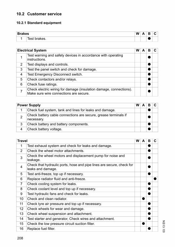
03.1
3 E
N
208
10.2 Customer service
10.2.1 Standard equipment
Brakes W A B C1 Test brakes. t
Electrical System W A B C
1 Test warning and safety devices in accordance with operating instructions. t
2 Test displays and controls. t3 Test the panel switch and check for damage. t4 Test Emergency Disconnect switch. t5 Check contactors and/or relays. t6 Check fuse ratings. t
7 Check electric wiring for damage (insulation damage, connections). Make sure wire connections are secure. t
Power Supply W A B C1 Check fuel system, tank and lines for leaks and damage. t
2 Check battery cable connections are secure, grease terminals if necessary. t
3 Check battery and battery components. t4 Check battery voltage. t
Travel W A B C1 Test exhaust system and check for leaks and damage. t2 Check the wheel motor attachments. t
3 Check the wheel motors and displacement pump for noise and leakage. t
4 Check that hydraulic ports, hose and pipe lines are secure, check for leaks and damage. t
5 Test anti-freeze, top up if necessary. t6 Replace radiator fluid and anti-freeze. t7 Check cooling system for leaks. t8 Check coolant level and top up if necessary. t9 Test hydraulic fans and check for leaks. t
10 Check and clean radiator. t11 Check tyre air pressure and top up if necessary. t12 Check wheels for wear and damage. t13 Check wheel suspension and attachment. t14 Test starter and generator, Check wires and attachment. t15 Check the low pressure circuit suction filter. t16 Replace fuel filter. t
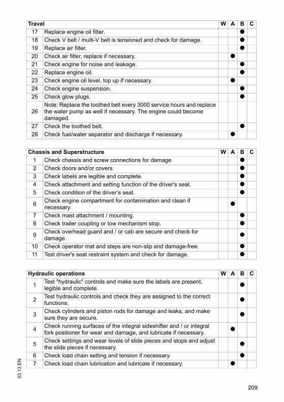
209
03.1
3 E
N
17 Replace engine oil filter. t18 Check V belt / multi-V belt is tensioned and check for damage. t19 Replace air filter. t20 Check air filter, replace if necessary. t21 Check engine for noise and leakage. t22 Replace engine oil. t23 Check engine oil level, top up if necessary. t24 Check engine suspension. t25 Check glow plugs. t
26Note: Replace the toothed belt every 3000 service hours and replace the water pump as well if necessary. The engine could become damaged.
27 Check the toothed belt. t28 Check fuel/water separator and discharge if necessary. t
Chassis and Superstructure W A B C1 Check chassis and screw connections for damage. t2 Check doors and/or covers. t3 Check labels are legible and complete. t4 Check attachment and setting function of the driver's seat. t5 Check condition of the driver’s seat. t
6 Check engine compartment for contamination and clean if necessary. t
7 Check mast attachment / mounting. t8 Check trailer coupling or tow mechanism stop. t
9 Check overhead guard and / or cab are secure and check for damage. t
10 Check operator mat and steps are non-slip and damage-free. t11 Test driver's seat restraint system and check for damage. t
Hydraulic operations W A B C
1 Test "hydraulic" controls and make sure the labels are present, legible and complete. t
2 Test hydraulic controls and check they are assigned to the correct functions. t
3 Check cylinders and piston rods for damage and leaks, and make sure they are secure. t
4 Check running surfaces of the integral sideshifter and / or integral fork positioner for wear and damage, and lubricate if necessary. t
5 Check settings and wear levels of slide pieces and stops and adjust the slide pieces if necessary. t
6 Check load chain setting and tension if necessary. t7 Check load chain lubrication and lubricate if necessary. t
Travel W A B C
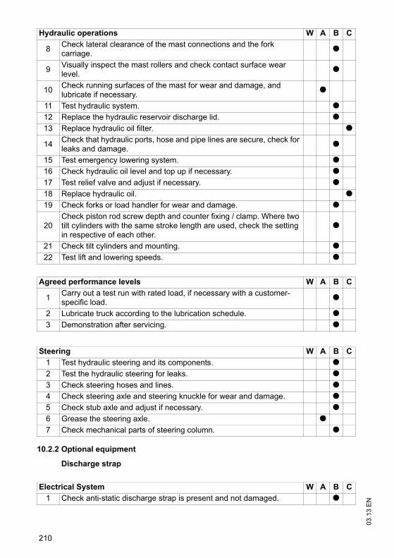
03.1
3 E
N
210
10.2.2 Optional equipment
Discharge strap
8 Check lateral clearance of the mast connections and the fork carriage. t
9 Visually inspect the mast rollers and check contact surface wear level. t
10 Check running surfaces of the mast for wear and damage, and lubricate if necessary. t
11 Test hydraulic system. t12 Replace the hydraulic reservoir discharge lid. t13 Replace hydraulic oil filter. t
14 Check that hydraulic ports, hose and pipe lines are secure, check for leaks and damage. t
15 Test emergency lowering system. t16 Check hydraulic oil level and top up if necessary. t17 Test relief valve and adjust if necessary. t18 Replace hydraulic oil. t19 Check forks or load handler for wear and damage. t
20Check piston rod screw depth and counter fixing / clamp. Where two tilt cylinders with the same stroke length are used, check the setting in respective of each other.
t
21 Check tilt cylinders and mounting. t22 Test lift and lowering speeds. t
Agreed performance levels W A B C
1 Carry out a test run with rated load, if necessary with a customer-specific load. t
2 Lubricate truck according to the lubrication schedule. t3 Demonstration after servicing. t
Steering W A B C1 Test hydraulic steering and its components. t2 Test the hydraulic steering for leaks. t3 Check steering hoses and lines. t4 Check steering axle and steering knuckle for wear and damage. t5 Check stub axle and adjust if necessary. t6 Grease the steering axle. t7 Check mechanical parts of steering column. t
Electrical System W A B C1 Check anti-static discharge strap is present and not damaged. t
Hydraulic operations W A B C
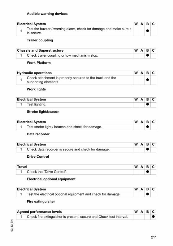
211
03.1
3 E
NAudible warning devices
Trailer coupling
Work Platform
Work lights
Strobe light/beacon
Data recorder
Drive Control
Electrical optional equipment
Fire extinguisher
Electrical System W A B C
1 Test the buzzer / warning alarm, check for damage and make sure it is secure. t
Chassis and Superstructure W A B C1 Check trailer coupling or tow mechanism stop. t
Hydraulic operations W A B C
1 Check attachment is properly secured to the truck and the supporting elements. t
Electrical System W A B C1 Test lighting. t
Electrical System W A B C1 Test strobe light / beacon and check for damage. t
Electrical System W A B C1 Check data recorder is secure and check for damage. t
Travel W A B C1 Check the "Drive Control". t
Electrical System W A B C1 Test the electrical optional equipment and check for damage. t
Agreed performance levels W A B C1 Check fire extinguisher is present, secure and Check test interval. t
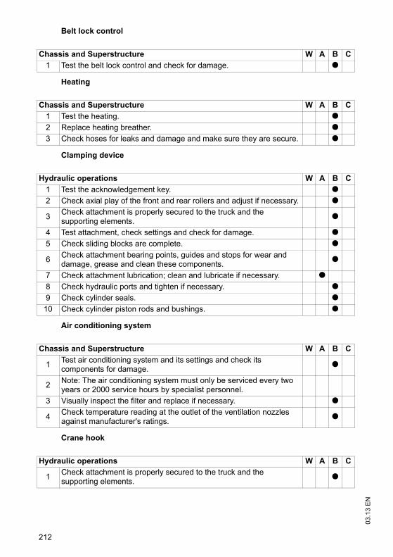
03.1
3 E
N
212
Belt lock control
Heating
Clamping device
Air conditioning system
Crane hook
Chassis and Superstructure W A B C1 Test the belt lock control and check for damage. t
Chassis and Superstructure W A B C1 Test the heating. t2 Replace heating breather. t3 Check hoses for leaks and damage and make sure they are secure. t
Hydraulic operations W A B C1 Test the acknowledgement key. t2 Check axial play of the front and rear rollers and adjust if necessary. t
3 Check attachment is properly secured to the truck and the supporting elements. t
4 Test attachment, check settings and check for damage. t5 Check sliding blocks are complete. t
6 Check attachment bearing points, guides and stops for wear and damage, grease and clean these components. t
7 Check attachment lubrication; clean and lubricate if necessary. t8 Check hydraulic ports and tighten if necessary. t9 Check cylinder seals. t
10 Check cylinder piston rods and bushings. t
Chassis and Superstructure W A B C
1 Test air conditioning system and its settings and check its components for damage. t
2 Note: The air conditioning system must only be serviced every two years or 2000 service hours by specialist personnel.
3 Visually inspect the filter and replace if necessary. t
4 Check temperature reading at the outlet of the ventilation nozzles against manufacturer's ratings. t
Hydraulic operations W A B C
1 Check attachment is properly secured to the truck and the supporting elements. t
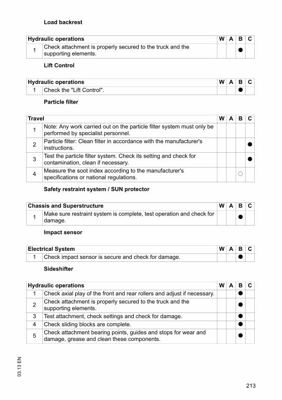
213
03.1
3 E
NLoad backrest
Lift Control
Particle filter
Safety restraint system / SUN protector
Impact sensor
Sideshifter
Hydraulic operations W A B C
1 Check attachment is properly secured to the truck and the supporting elements. t
Hydraulic operations W A B C1 Check the "Lift Control". t
Travel W A B C
1 Note: Any work carried out on the particle filter system must only be performed by specialist personnel.
2 Particle filter: Clean filter in accordance with the manufacturer's instructions. t
3 Test the particle filter system. Check its setting and check for contamination, clean if necessary. t
4 Measure the soot index according to the manufacturer's specifications or national regulations. o
Chassis and Superstructure W A B C
1 Make sure restraint system is complete, test operation and check for damage. t
Electrical System W A B C1 Check impact sensor is secure and check for damage. t
Hydraulic operations W A B C1 Check axial play of the front and rear rollers and adjust if necessary. t
2 Check attachment is properly secured to the truck and the supporting elements. t
3 Test attachment, check settings and check for damage. t4 Check sliding blocks are complete. t
5 Check attachment bearing points, guides and stops for wear and damage, grease and clean these components. t
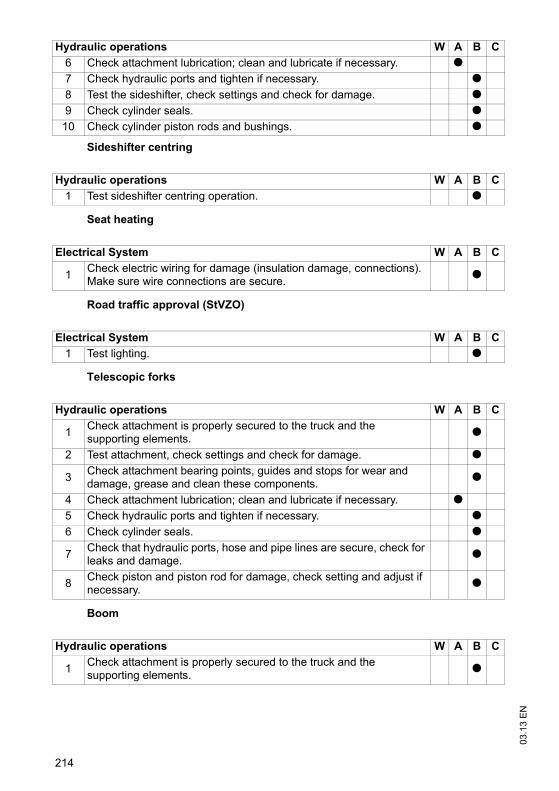
03.1
3 E
N
214
Sideshifter centring
Seat heating
Road traffic approval (StVZO)
Telescopic forks
Boom
6 Check attachment lubrication; clean and lubricate if necessary. t7 Check hydraulic ports and tighten if necessary. t8 Test the sideshifter, check settings and check for damage. t9 Check cylinder seals. t
10 Check cylinder piston rods and bushings. t
Hydraulic operations W A B C1 Test sideshifter centring operation. t
Electrical System W A B C
1 Check electric wiring for damage (insulation damage, connections). Make sure wire connections are secure. t
Electrical System W A B C1 Test lighting. t
Hydraulic operations W A B C
1 Check attachment is properly secured to the truck and the supporting elements. t
2 Test attachment, check settings and check for damage. t
3 Check attachment bearing points, guides and stops for wear and damage, grease and clean these components. t
4 Check attachment lubrication; clean and lubricate if necessary. t5 Check hydraulic ports and tighten if necessary. t6 Check cylinder seals. t
7 Check that hydraulic ports, hose and pipe lines are secure, check for leaks and damage. t
8 Check piston and piston rod for damage, check setting and adjust if necessary. t
Hydraulic operations W A B C
1 Check attachment is properly secured to the truck and the supporting elements. t
Hydraulic operations W A B C
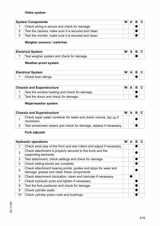
215
03.1
3 E
NVideo system
Weigher sensors / switches
Weather-proof system
Wiper/washer system
Fork adjuster
System Components W A B C1 Check wiring is secure and check for damage. t2 Test the camera, make sure it is secured and clean. t3 Test the monitor, make sure it is secured and clean. t
Electrical System W A B C1 Test weigher system and check for damage. t
Electrical System W A B C1 Check fuse ratings. t
Chassis and Superstructure W A B C1 Test the window heating and check for damage. t2 Test the doors and check for damage. t
Chassis and Superstructure W A B C
1 Check wiper water container for leaks and check volume, top up if necessary. t
2 Test windscreen wipers and check for damage, replace if necessary. t
Hydraulic operations W A B C1 Check axial play of the front and rear rollers and adjust if necessary. t
2 Check attachment is properly secured to the truck and the supporting elements. t
3 Test attachment, check settings and check for damage. t4 Check sliding blocks are complete. t
5 Check attachment bearing points, guides and stops for wear and damage, grease and clean these components. t
6 Check attachment lubrication; clean and lubricate if necessary. t7 Check hydraulic ports and tighten if necessary. t8 Test the fork positioner and check for damage. t9 Check cylinder seals. t
10 Check cylinder piston rods and bushings. t

03.1
3 E
N
216
Access module
Optional equipment
Issued on: 20.11.2012 16:22:57
Electrical System W A B C1 Test access module, check for damage and make sure it is secure. t
Chassis and Superstructure W A B C
1Check that optional equipment such as mirrors, storage compartments, grips, windscreen wipers and washing systems etc. are working correctly and check for damage.
t
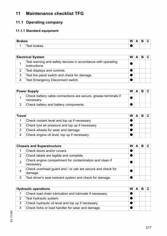
217
03.1
3 E
N11 Maintenance checklist TFG
11.1 Operating company
11.1.1 Standard equipment
Brakes W A B C1 Test brakes. t
Electrical System W A B C
1 Test warning and safety devices in accordance with operating instructions. t
2 Test displays and controls. t3 Test the panel switch and check for damage. t4 Test Emergency Disconnect switch. t
Power Supply W A B C
1 Check battery cable connections are secure, grease terminals if necessary. t
2 Check battery and battery components. t
Travel W A B C1 Check coolant level and top up if necessary. t2 Check tyre air pressure and top up if necessary. t3 Check wheels for wear and damage. t4 Check engine oil level, top up if necessary. t
Chassis and Superstructure W A B C1 Check doors and/or covers. t2 Check labels are legible and complete. t
3 Check engine compartment for contamination and clean if necessary. t
4 Check overhead guard and / or cab are secure and check for damage. t
5 Test driver's seat restraint system and check for damage. t
Hydraulic operations W A B C1 Check load chain lubrication and lubricate if necessary. t2 Test hydraulic system. t3 Check hydraulic oil level and top up if necessary. t4 Check forks or load handler for wear and damage. t

03.1
3 E
N
218
11.1.2 Optional equipment
Work lights
Strobe light/beacon
Heating
Clamping device
Sideshifter
Road traffic approval (StVZO)
Telescopic forks
Weather-proof system
Wiper/washer system
Electrical System W A B C1 Test lighting. t
Electrical System W A B C1 Test strobe light / beacon and check for damage. t
Chassis and Superstructure W A B C1 Test the heating. t2 Check heating vent filter for contamination and clean if necessary. t
Hydraulic operations W A B C1 Check attachment lubrication; clean and lubricate if necessary. t
Hydraulic operations W A B C1 Check attachment lubrication; clean and lubricate if necessary. t
Electrical System W A B C1 Test lighting. t
Hydraulic operations W A B C1 Check attachment lubrication; clean and lubricate if necessary. t
Chassis and Superstructure W A B C1 Test the doors and check for damage. t
Chassis and Superstructure W A B C
1 Check wiper water container for leaks and check volume, top up if necessary. t

219
03.1
3 E
NFork adjuster
Optional equipment
Hydraulic operations W A B C1 Check attachment lubrication; clean and lubricate if necessary. t
Chassis and Superstructure W A B C
1Check that optional equipment such as mirrors, storage compartments, grips, windscreen wipers and washing systems etc. are working correctly and check for damage.
t
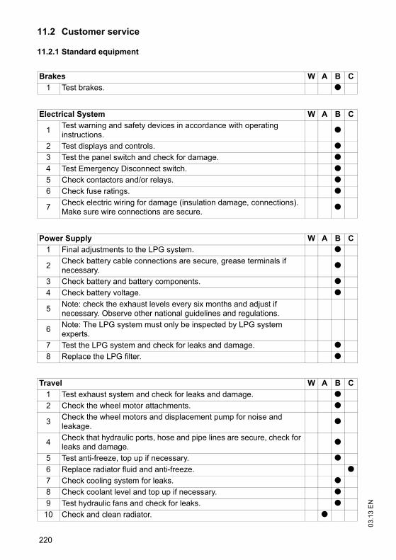
03.1
3 E
N
220
11.2 Customer service
11.2.1 Standard equipment
Brakes W A B C1 Test brakes. t
Electrical System W A B C
1 Test warning and safety devices in accordance with operating instructions. t
2 Test displays and controls. t3 Test the panel switch and check for damage. t4 Test Emergency Disconnect switch. t5 Check contactors and/or relays. t6 Check fuse ratings. t
7 Check electric wiring for damage (insulation damage, connections). Make sure wire connections are secure. t
Power Supply W A B C1 Final adjustments to the LPG system. t
2 Check battery cable connections are secure, grease terminals if necessary. t
3 Check battery and battery components. t4 Check battery voltage. t
5 Note: check the exhaust levels every six months and adjust if necessary. Observe other national guidelines and regulations.
6 Note: The LPG system must only be inspected by LPG system experts.
7 Test the LPG system and check for leaks and damage. t8 Replace the LPG filter. t
Travel W A B C1 Test exhaust system and check for leaks and damage. t2 Check the wheel motor attachments. t
3 Check the wheel motors and displacement pump for noise and leakage. t
4 Check that hydraulic ports, hose and pipe lines are secure, check for leaks and damage. t
5 Test anti-freeze, top up if necessary. t6 Replace radiator fluid and anti-freeze. t7 Check cooling system for leaks. t8 Check coolant level and top up if necessary. t9 Test hydraulic fans and check for leaks. t
10 Check and clean radiator. t
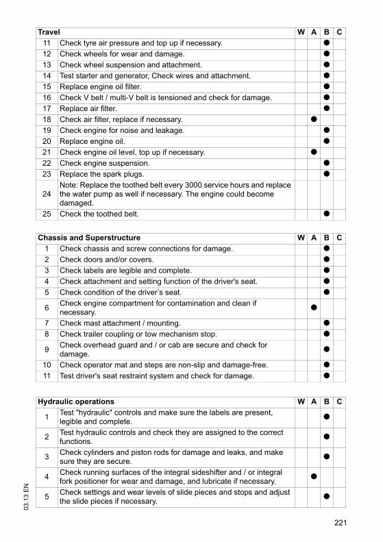
221
03.1
3 E
N
11 Check tyre air pressure and top up if necessary. t12 Check wheels for wear and damage. t13 Check wheel suspension and attachment. t14 Test starter and generator, Check wires and attachment. t15 Replace engine oil filter. t16 Check V belt / multi-V belt is tensioned and check for damage. t17 Replace air filter. t18 Check air filter, replace if necessary. t19 Check engine for noise and leakage. t20 Replace engine oil. t21 Check engine oil level, top up if necessary. t22 Check engine suspension. t23 Replace the spark plugs. t
24Note: Replace the toothed belt every 3000 service hours and replace the water pump as well if necessary. The engine could become damaged.
25 Check the toothed belt. t
Chassis and Superstructure W A B C1 Check chassis and screw connections for damage. t2 Check doors and/or covers. t3 Check labels are legible and complete. t4 Check attachment and setting function of the driver's seat. t5 Check condition of the driver’s seat. t
6 Check engine compartment for contamination and clean if necessary. t
7 Check mast attachment / mounting. t8 Check trailer coupling or tow mechanism stop. t
9 Check overhead guard and / or cab are secure and check for damage. t
10 Check operator mat and steps are non-slip and damage-free. t11 Test driver's seat restraint system and check for damage. t
Hydraulic operations W A B C
1 Test "hydraulic" controls and make sure the labels are present, legible and complete. t
2 Test hydraulic controls and check they are assigned to the correct functions. t
3 Check cylinders and piston rods for damage and leaks, and make sure they are secure. t
4 Check running surfaces of the integral sideshifter and / or integral fork positioner for wear and damage, and lubricate if necessary. t
5 Check settings and wear levels of slide pieces and stops and adjust the slide pieces if necessary. t
Travel W A B C
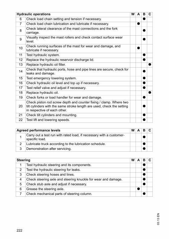
03.1
3 E
N
222
6 Check load chain setting and tension if necessary. t7 Check load chain lubrication and lubricate if necessary. t
8 Check lateral clearance of the mast connections and the fork carriage. t
9 Visually inspect the mast rollers and check contact surface wear level. t
10 Check running surfaces of the mast for wear and damage, and lubricate if necessary. t
11 Test hydraulic system. t12 Replace the hydraulic reservoir discharge lid. t13 Replace hydraulic oil filter. t
14 Check that hydraulic ports, hose and pipe lines are secure, check for leaks and damage. t
15 Test emergency lowering system. t16 Check hydraulic oil level and top up if necessary. t17 Test relief valve and adjust if necessary. t18 Replace hydraulic oil. t19 Check forks or load handler for wear and damage. t
20Check piston rod screw depth and counter fixing / clamp. Where two tilt cylinders with the same stroke length are used, check the setting in respective of each other.
t
21 Check tilt cylinders and mounting. t22 Test lift and lowering speeds. t
Agreed performance levels W A B C
1 Carry out a test run with rated load, if necessary with a customer-specific load. t
2 Lubricate truck according to the lubrication schedule. t3 Demonstration after servicing. t
Steering W A B C1 Test hydraulic steering and its components. t2 Test the hydraulic steering for leaks. t3 Check steering hoses and lines. t4 Check steering axle and steering knuckle for wear and damage. t5 Check stub axle and adjust if necessary. t6 Grease the steering axle. t7 Check mechanical parts of steering column. t
Hydraulic operations W A B C
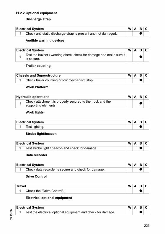
223
03.1
3 E
N11.2.2 Optional equipment
Discharge strap
Audible warning devices
Trailer coupling
Work Platform
Work lights
Strobe light/beacon
Data recorder
Drive Control
Electrical optional equipment
Electrical System W A B C1 Check anti-static discharge strap is present and not damaged. t
Electrical System W A B C
1 Test the buzzer / warning alarm, check for damage and make sure it is secure. t
Chassis and Superstructure W A B C1 Check trailer coupling or tow mechanism stop. t
Hydraulic operations W A B C
1 Check attachment is properly secured to the truck and the supporting elements. t
Electrical System W A B C1 Test lighting. t
Electrical System W A B C1 Test strobe light / beacon and check for damage. t
Electrical System W A B C1 Check data recorder is secure and check for damage. t
Travel W A B C1 Check the "Drive Control". t
Electrical System W A B C1 Test the electrical optional equipment and check for damage. t
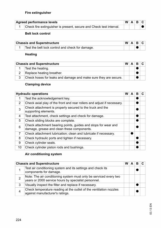
03.1
3 E
N
224
Fire extinguisher
Belt lock control
Heating
Clamping device
Air conditioning system
Agreed performance levels W A B C1 Check fire extinguisher is present, secure and Check test interval. t
Chassis and Superstructure W A B C1 Test the belt lock control and check for damage. t
Chassis and Superstructure W A B C1 Test the heating. t2 Replace heating breather. t3 Check hoses for leaks and damage and make sure they are secure. t
Hydraulic operations W A B C1 Test the acknowledgement key. t2 Check axial play of the front and rear rollers and adjust if necessary. t
3 Check attachment is properly secured to the truck and the supporting elements. t
4 Test attachment, check settings and check for damage. t5 Check sliding blocks are complete. t
6 Check attachment bearing points, guides and stops for wear and damage, grease and clean these components. t
7 Check attachment lubrication; clean and lubricate if necessary. t8 Check hydraulic ports and tighten if necessary. t9 Check cylinder seals. t
10 Check cylinder piston rods and bushings. t
Chassis and Superstructure W A B C
1 Test air conditioning system and its settings and check its components for damage. t
2 Note: The air conditioning system must only be serviced every two years or 2000 service hours by specialist personnel.
3 Visually inspect the filter and replace if necessary. t
4 Check temperature reading at the outlet of the ventilation nozzles against manufacturer's ratings. t
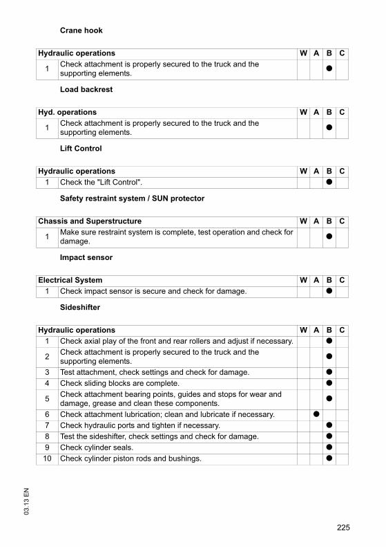
225
03.1
3 E
NCrane hook
Load backrest
Lift Control
Safety restraint system / SUN protector
Impact sensor
Sideshifter
Hydraulic operations W A B C
1 Check attachment is properly secured to the truck and the supporting elements. t
Hyd. operations W A B C
1 Check attachment is properly secured to the truck and the supporting elements. t
Hydraulic operations W A B C1 Check the "Lift Control". t
Chassis and Superstructure W A B C
1 Make sure restraint system is complete, test operation and check for damage. t
Electrical System W A B C1 Check impact sensor is secure and check for damage. t
Hydraulic operations W A B C1 Check axial play of the front and rear rollers and adjust if necessary. t
2 Check attachment is properly secured to the truck and the supporting elements. t
3 Test attachment, check settings and check for damage. t4 Check sliding blocks are complete. t
5 Check attachment bearing points, guides and stops for wear and damage, grease and clean these components. t
6 Check attachment lubrication; clean and lubricate if necessary. t7 Check hydraulic ports and tighten if necessary. t8 Test the sideshifter, check settings and check for damage. t9 Check cylinder seals. t
10 Check cylinder piston rods and bushings. t
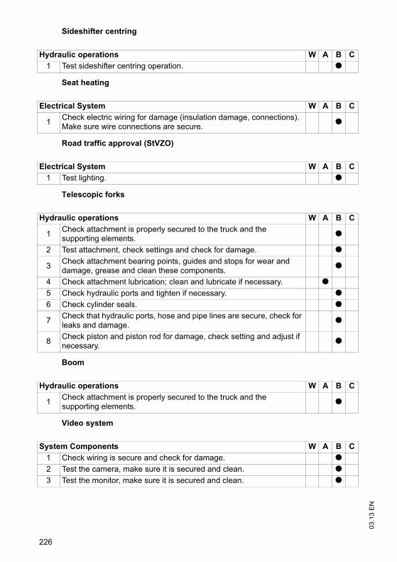
03.1
3 E
N
226
Sideshifter centring
Seat heating
Road traffic approval (StVZO)
Telescopic forks
Boom
Video system
Hydraulic operations W A B C1 Test sideshifter centring operation. t
Electrical System W A B C
1 Check electric wiring for damage (insulation damage, connections). Make sure wire connections are secure. t
Electrical System W A B C1 Test lighting. t
Hydraulic operations W A B C
1 Check attachment is properly secured to the truck and the supporting elements. t
2 Test attachment, check settings and check for damage. t
3 Check attachment bearing points, guides and stops for wear and damage, grease and clean these components. t
4 Check attachment lubrication; clean and lubricate if necessary. t5 Check hydraulic ports and tighten if necessary. t6 Check cylinder seals. t
7 Check that hydraulic ports, hose and pipe lines are secure, check for leaks and damage. t
8 Check piston and piston rod for damage, check setting and adjust if necessary. t
Hydraulic operations W A B C
1 Check attachment is properly secured to the truck and the supporting elements. t
System Components W A B C1 Check wiring is secure and check for damage. t2 Test the camera, make sure it is secured and clean. t3 Test the monitor, make sure it is secured and clean. t
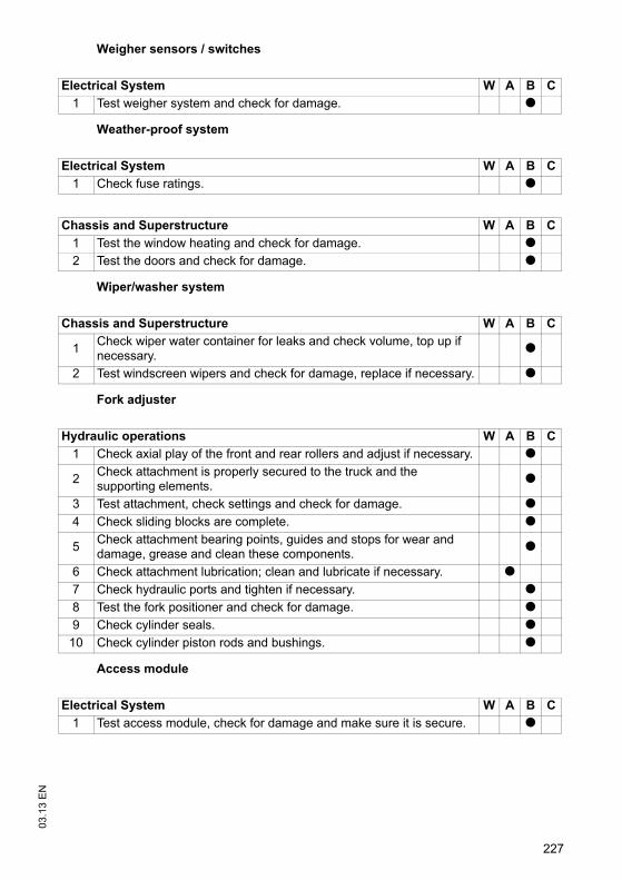
227
03.1
3 E
NWeigher sensors / switches
Weather-proof system
Wiper/washer system
Fork adjuster
Access module
Electrical System W A B C1 Test weigher system and check for damage. t
Electrical System W A B C1 Check fuse ratings. t
Chassis and Superstructure W A B C1 Test the window heating and check for damage. t2 Test the doors and check for damage. t
Chassis and Superstructure W A B C
1 Check wiper water container for leaks and check volume, top up if necessary. t
2 Test windscreen wipers and check for damage, replace if necessary. t
Hydraulic operations W A B C1 Check axial play of the front and rear rollers and adjust if necessary. t
2 Check attachment is properly secured to the truck and the supporting elements. t
3 Test attachment, check settings and check for damage. t4 Check sliding blocks are complete. t
5 Check attachment bearing points, guides and stops for wear and damage, grease and clean these components. t
6 Check attachment lubrication; clean and lubricate if necessary. t7 Check hydraulic ports and tighten if necessary. t8 Test the fork positioner and check for damage. t9 Check cylinder seals. t
10 Check cylinder piston rods and bushings. t
Electrical System W A B C1 Test access module, check for damage and make sure it is secure. t

03.1
3 E
N
228
Optional equipment
Issued on: 20.11.2012 16:52:11
Chassis and Superstructure W A B C
1Check that optional equipment such as mirrors, storage compartments, grips, windscreen wipers and washing systems etc. are working correctly and check for damage.
t