Embed Size (px)
Citation preview
Local address:
Sauer-Danfoss GmbH & Co. OHGPostfach 2460, D-24531 NeumünsterKrokamp 35, D-24539 Neumünster, GermanyPhone: +49 4321 871 0Fax: +49 4321 871 122
Sauer-Danfoss ApSDK-6430 Nordborg, DenmarkPhone: +45 7488 4444Fax: +45 7488 4400
Sauer-Danfoss is a global manufacturer and supplier of high-quality hydraulic and electronic components. We specialize in providing state-of-the-art technology and solutions that excel in the harsh operating conditions of the mobile o� -highway market. Building on our extensive applications expertise, we work closely with our customers to ensure exceptional performance for a broad range of o� -highway vehicles.
We help OEMs around the world speed up system development, reduce costs and bring vehicles to market faster. Sauer-Danfoss – Your Strongest Partner in Mobile Hydraulics.
Go to www.sauer-danfoss.com for further product information.
Wherever o� -highway vehicles are at work, so is Sauer-Danfoss.
We o� er expert worldwide support for our customers, ensuring the best possible solutions for outstanding performance. And with an extensive network of Global Service Partners, we also provide comprehensive global service for all of our components.
Please contact the Sauer-Danfoss representative nearest you.
Products we o� er:
• Bent Axis Motors
• Closed Circuit Axial Piston Pumps and Motors
• Displays
• Electrohydraulic Power Steering
• Electrohydraulics
• Hydraulic Power Steering
• Integrated Systems
• Joysticks and Control Handles
• Microcontrollers and Software
• Open Circuit Axial Piston Pumps
• Orbital Motors
• PLUS+1™ GUIDE
• Proportional Valves
• Sensors
• Steering
• Transit Mixer Drives
Members of the Sauer-Danfoss Group:
Comatrolwww.comatrol.com
Schwarzmüller-Inverterwww.schwarzmueller-inverter.com
Turolla www.turollaocg.com
Hydro-Gear www.hydro-gear.com
Sauer-Danfoss-Daikinwww.sauer-danfoss-daikin.com
Sauer-Danfoss (US) Company2800 East 13th StreetAmes, IA 50010, USAPhone: +1 515 239 6000Fax: +1 515 239 6618
Sauer-Danfoss-Daikin LTD.Shin-Osaka TERASAKI 3rd Bldg. 6F1-5-28 Nishimiyahara, Yodogawa-kuOsaka 532-0004, JapanPhone: +81 6 6395 6066Fax: +81 6 6395 8585
w w w . s a u e r - d a n f o s s . c o m
DH and DS Motors
Assembly and Test Procedures
2 11065435 • Rev AD • October 2011
DH and DS MotorsAssembly and Test Procedures
© 2011 Sauer-Danfoss. All rights reserved.
Sauer-Danfoss accepts no responsibility for possible errors in catalogs, brochures and other printed material. Sauer-Danfoss reserves the right to alter its products without prior notice. This also applies to products already ordered provided that such alterations aren’t in conflict with agreed specifications. All trademarks in this material are properties of their respective owners. Sauer-Danfoss and the Sauer-Danfoss logotype are trademarks of the Sauer-Danfoss Group.
Revisions
Table of RevisionsDate Page Changed Rev.
October 2011 4 edits to General Instructions ADOctober 2010 last new back page AC
March 2010 last Fix Osaka address AB
April 2009 - First edition AA
History of Revisions
311065435 • Rev AD • October 2011
DH and DS MotorsAssembly and Test ProceduresContents
Introduction
Tools
Motor Identification
Assembly
Testing
Assembly Drawings
Overview ........................................................................................................................................................... 4General Instructions ...................................................................................................................................... 4Safety Precautions.......................................................................................................................................... 5
Unintended Machine Movement ........................................................................................................ 5Flammable Cleaning Solvents .............................................................................................................. 5Fluid Under Pressure ................................................................................................................................ 5Personal Safety .......................................................................................................................................... 5Hazardous Material .................................................................................................................................. 5
Tools .................................................................................................................................................................... 6
Module Components .................................................................................................................................... 8Motor Assembly .............................................................................................................................................. 9
Testing Assembled Motor .........................................................................................................................13Hydraulic Schematic ....................................................................................................................................15
Motor Identification ....................................................................................................................................16
DH Exploded View .......................................................................................................................................17DS Exploded View ........................................................................................................................................18
4 11065435 • Rev AD • October 2011
DH and DS MotorsAssembly and Test ProceduresIntroduction
Overview
Follow these general procedures when assembling DH and DS Motors.
e Keep it cleanAs with any precision equipment, keep all parts free of foreign materials and chemicals. Protect all exposed sealing surfaces and open cavities from damage and foreign material. If left unattended, cover the motor with a protective layer of plastic.
d Lubricate O-ringsLightly lubricate all O-rings with clean petroleum jelly prior to assembly.
General Instructions
This manual includes information on assembly and testing of DH and DS Motors.
To provide timely motor delivery when a customer places an order, you need to have all the necessary modules and equipment on hand.
DH and DS motor assembly is based on a modular building concept. Each motor consists of two modules; the housing module and the gear wheel set module. When assembled, these two modules constitute a complete motor.
The variation in motor size (displacement) is determined by the gear wheel set module. One housing module is common for all motors of a given flange type.

511065435 • Rev AD • October 2011
DH and DS MotorsAssembly and Test ProceduresIntroduction
Safety Precautions Always consider safety precautions before beginning a service procedure. Protect yourself and others from injury. Take the following general precautions whenever servicing a hydraulic system.
Unintended Machine MovementW WarningUnintended movement of the machine or mechanism may cause injury to the technician or bystanders. To protect against unintended movement, secure the machine or disable/disconnect the mechanism while servicing.
Flammable Cleaning SolventsW WarningSome cleaning solvents are flammable. To avoid possible fire, do not use cleaning solvents in an area where a source of ignition may be present.
Fluid Under PressureW WarningEscaping hydraulic fluid under pressure can have sufficient force to penetrate your skin causing serious injury and/or infection. This fluid may also be hot enough to cause burns. Use caution when dealing with hydraulic fluid under pressure. Relieve pressure in the system before removing hoses, fittings, gauges, or components. Never use your hand or any other body part to check for leaks in a pressurized line. Seek medical attention immediately if you are cut by hydraulic fluid.
Personal SafetyW WarningProtect yourself from injury. Use proper safety equipment, including safety glasses, at all times.
Hazardous MaterialW WarningHydraulic fluid contains hazardous material. Avoid prolonged contact with hydraulic fluid. Always dispose of used hydraulic fluid according to state, and federal environmental regulations.
6 11065435 • Rev AD • October 2011
DH and DS MotorsAssembly and Test ProceduresTools
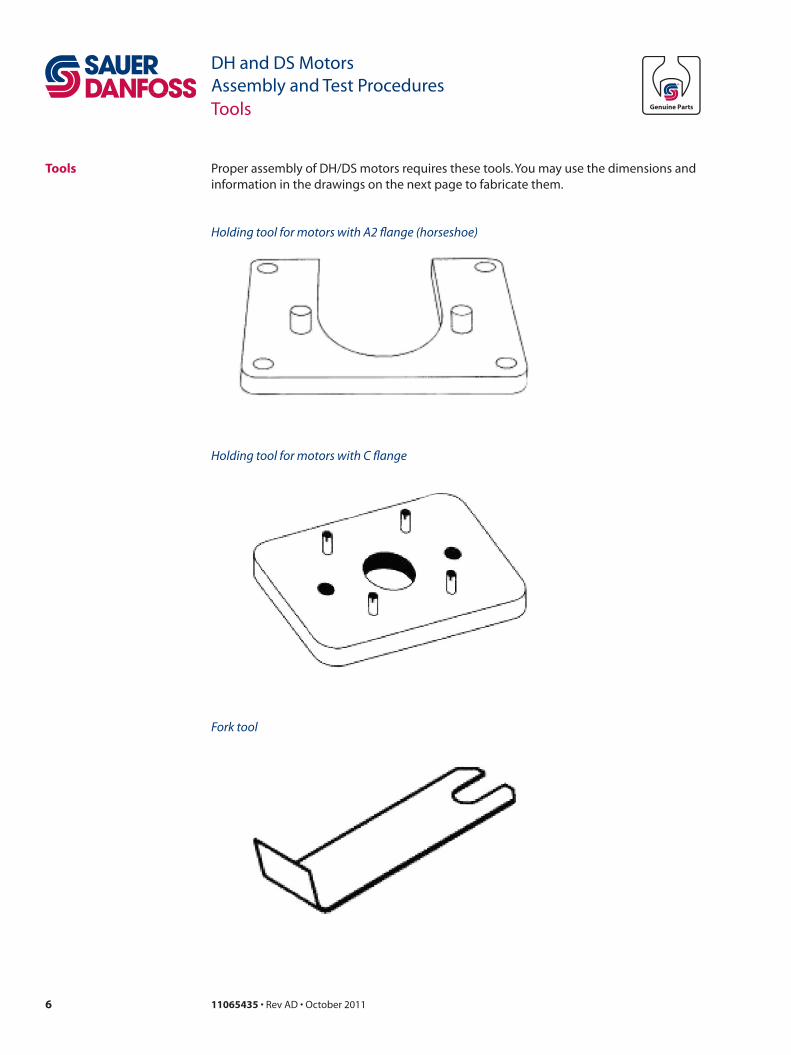
Tools Proper assembly of DH/DS motors requires these tools. You may use the dimensions and information in the drawings on the next page to fabricate them.
Holding tool for motors with A2 flange (horseshoe)
Holding tool for motors with C flange
Fork tool
711065435 • Rev AD • October 2011
DH and DS MotorsAssembly and Test ProceduresTools
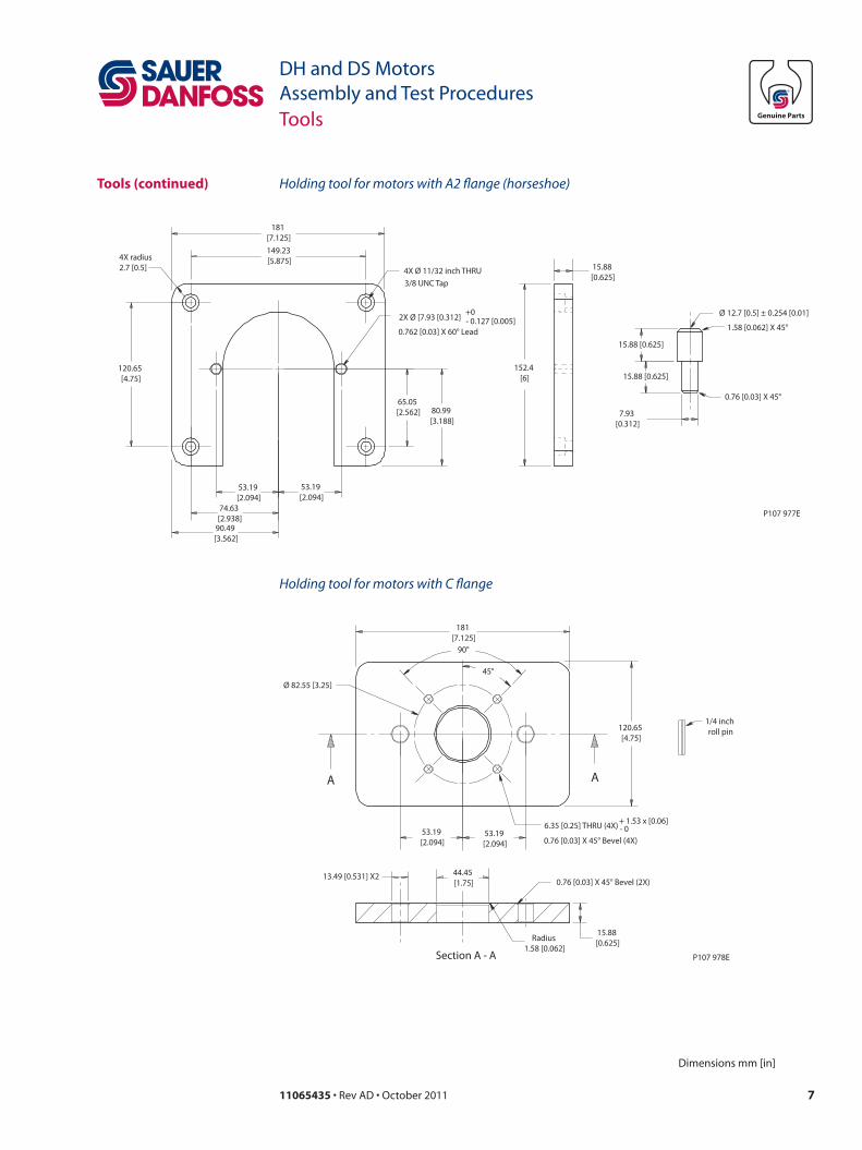
Tools (continued)
Ø 12.7 [0.5] ± 0.254 [0.01]
1.58 [0.062] X 45°
15.88 [0.625]
0.76 [0.03] X 45°
15.88 [0.625]
7.93 [0.312]
- 0.127 [0.005]+0
15.88 [0.625]
152.4 [6]
80.99 [3.188]
65.05 [2.562]
53.19 [2.094]
53.19 [2.094]
74.63 [2.938]
90.49 [3.562]
120.65 [4.75]
4X radius2.7 [0.5]
181 [7.125]149.23 [5.875]
4X Ø 11/32 inch THRU3/8 UNC Tap
2X Ø [7.93 [0.312]
0.762 [0.03] X 60° Lead
P107 977E
Dimensions mm [in]
Holding tool for motors with A2 flange (horseshoe)
P107 978E
Ø 82.55 [3.25]
120.65 [4.75]
15.88 [0.625]
181 [7.125]
90°
45°
Radius 1.58 [0.062]
6.35 [0.25] THRU (4X) + 1.53 x [0.06]- 0
1/4 inch roll pin
0.76 [0.03] X 45° Bevel (2X)44.45 [1.75]
13.49 [0.531] X2
53.19 [2.094]
53.19 [2.094]
Section A - A
A A
0.76 [0.03] X 45° Bevel (4X)
Holding tool for motors with C flange
8 11065435 • Rev AD • October 2011
DH and DS MotorsAssembly and Test ProceduresModule Components
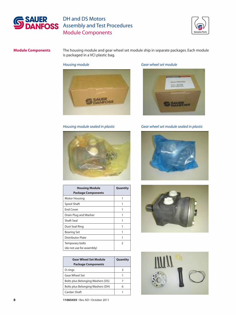
Module Components The housing module and gear wheel set module ship in separate packages. Each module is packaged in a VCI plastic bag.
Housing module Gear wheel set module
Housing module sealed in plastic Gear wheel set module sealed in plastic
Housing Module
Package Components
Quantity
Motor Housing 1
Spool Shaft 1
End Cover 1
Drain Plug and Washer 1
Shaft Seal 1
Dust Seal Ring 1
Bearing Set 1
Distributor Plate 1
Temporary bolts
(do not use for assembly)
2
Gear Wheel Set Module
Package Components
Quantity
O-rings 3
Gear Wheel Set 1
Bolts plus Belonging Washers (DS) 7
Bolts plus Belonging Washers (DH) 6
Cardan Shaft 1
911065435 • Rev AD • October 2011
DH and DS MotorsAssembly and Test ProceduresAssembly
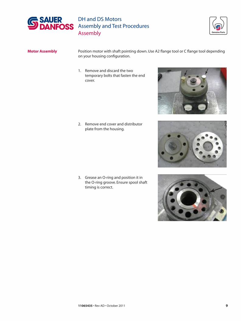
Motor Assembly Position motor with shaft pointing down. Use A2 flange tool or C flange tool depending on your housing configuration.
1. Remove and discard the two temporary bolts that fasten the end cover.
2. Remove end cover and distributor plate from the housing.
3. Grease an O-ring and position it in the O-ring groove. Ensure spool shaft timing is correct.
10 11065435 • Rev AD • October 2011
DH and DS MotorsAssembly and Test ProceduresAssembly
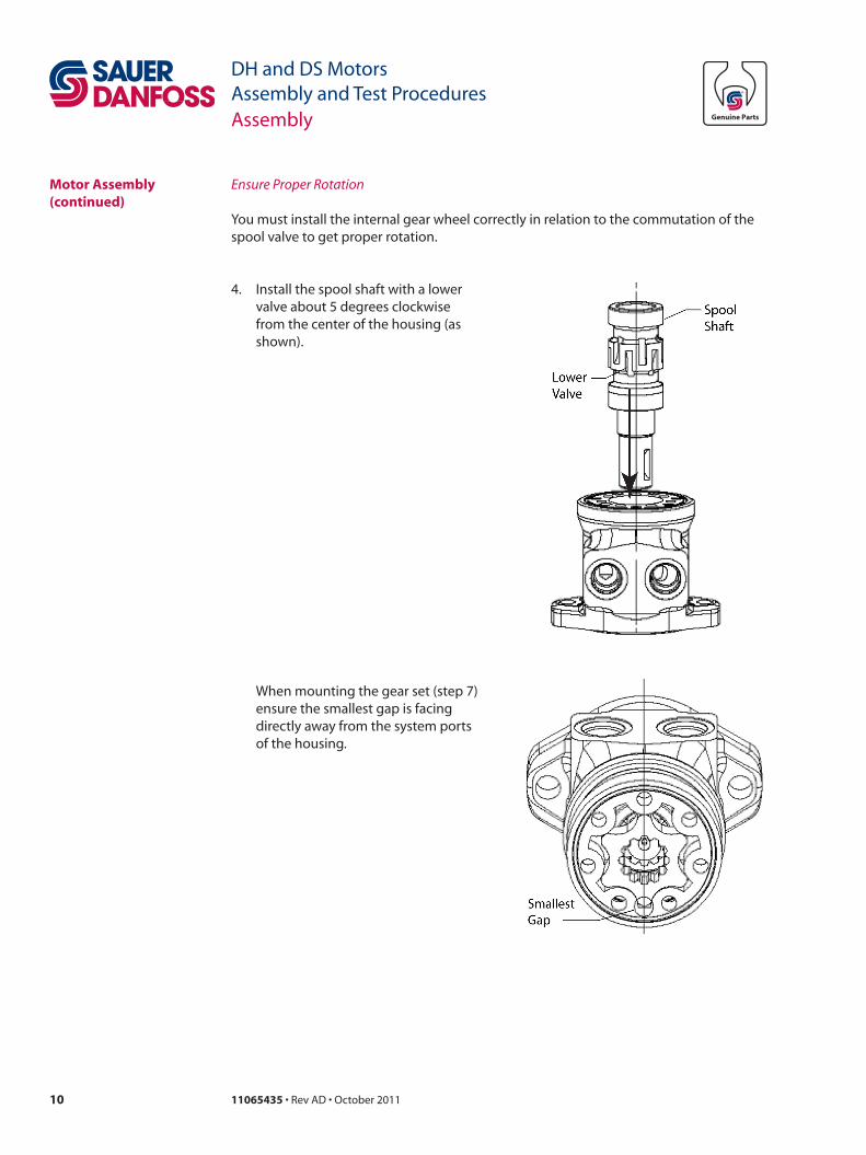
You must install the internal gear wheel correctly in relation to the commutation of the spool valve to get proper rotation.
4. Install the spool shaft with a lower valve about 5 degrees clockwise from the center of the housing (as shown).
When mounting the gear set (step 7) ensure the smallest gap is facing directly away from the system ports of the housing.
Motor Assembly (continued)
Ensure Proper Rotation
1111065435 • Rev AD • October 2011
DH and DS MotorsAssembly and Test ProceduresAssembly
Motor Assembly (continued)
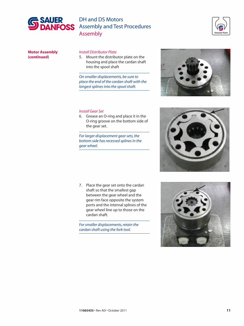
Install Distributor Plate5. Mount the distributor plate on the
housing and place the cardan shaft into the spool shaft
On smaller displacements, be sure to place the end of the cardan shaft with the longest splines into the spool shaft.
Install Gear Set6. Grease an O-ring and place it in the
O-ring groove on the bottom side of the gear set.
For larger displacement gear sets, the bottom side has recessed splines in the gear wheel.
7. Place the gear set onto the cardan shaft so that the smallest gap between the gear wheel and the gear rim face opposite the system ports and the internal splines of the gear wheel line up to those on the cardan shaft.
For smaller displacements, retain the cardan shaft using the fork tool.
12 11065435 • Rev AD • October 2011
DH and DS MotorsAssembly and Test ProceduresAssembly
Motor Assembly (continued)
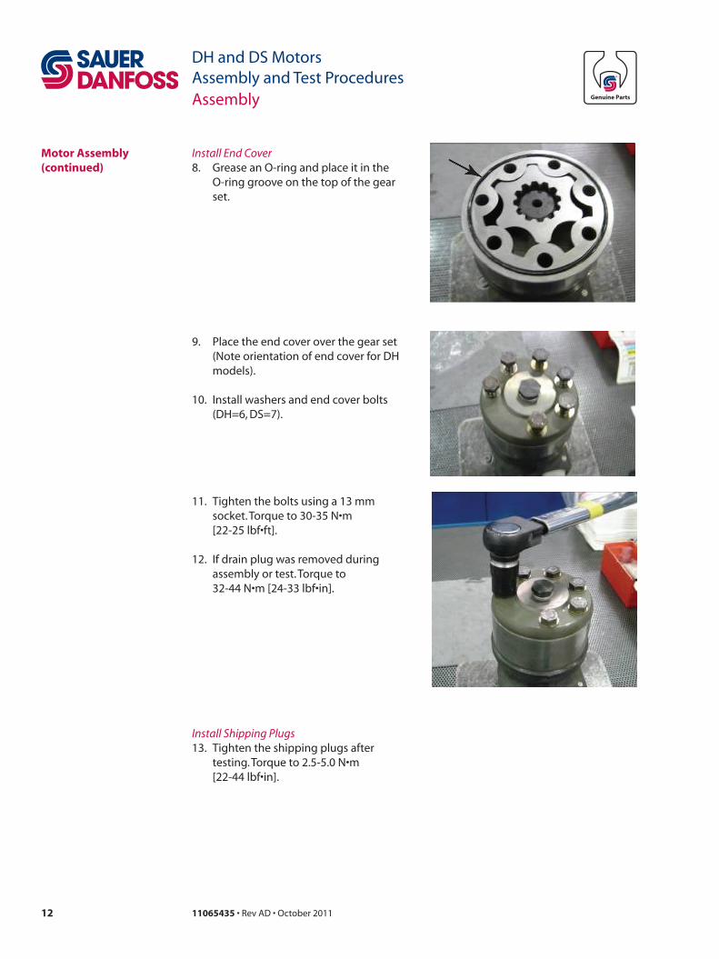
9. Place the end cover over the gear set (Note orientation of end cover for DH models).
10. Install washers and end cover bolts (DH=6, DS=7).
Install End Cover8. Grease an O-ring and place it in the
O-ring groove on the top of the gear set.
11. Tighten the bolts using a 13 mm socket. Torque to 30-35 N•m
[22-25 lbf•ft].
12. If drain plug was removed during assembly or test. Torque to
32-44 N•m [24-33 lbf•in].
Install Shipping Plugs13. Tighten the shipping plugs after
testing. Torque to 2.5-5.0 N•m [22-44 lbf•in].
1311065435 • Rev AD • October 2011
DH and DS MotorsAssembly and Test ProceduresTesting
Testing Assembled Motor Hydraulic Fluid Specifications
General Testing Conditions
Fluid type Mineral hydraulic oil class HM, ISO 6743/4
Viscosity range 35 ± 3 cSt
Oil cleanliness 18/13 – contamination degree, ISO 4406
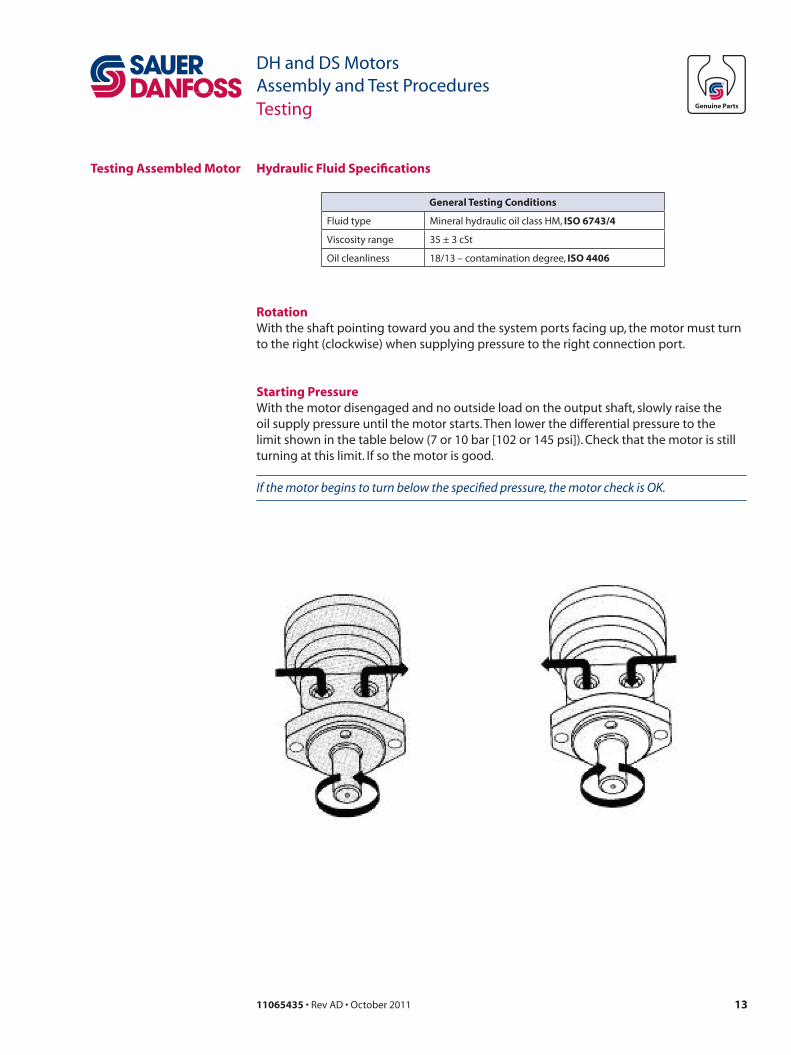
With the shaft pointing toward you and the system ports facing up, the motor must turn to the right (clockwise) when supplying pressure to the right connection port.
Rotation
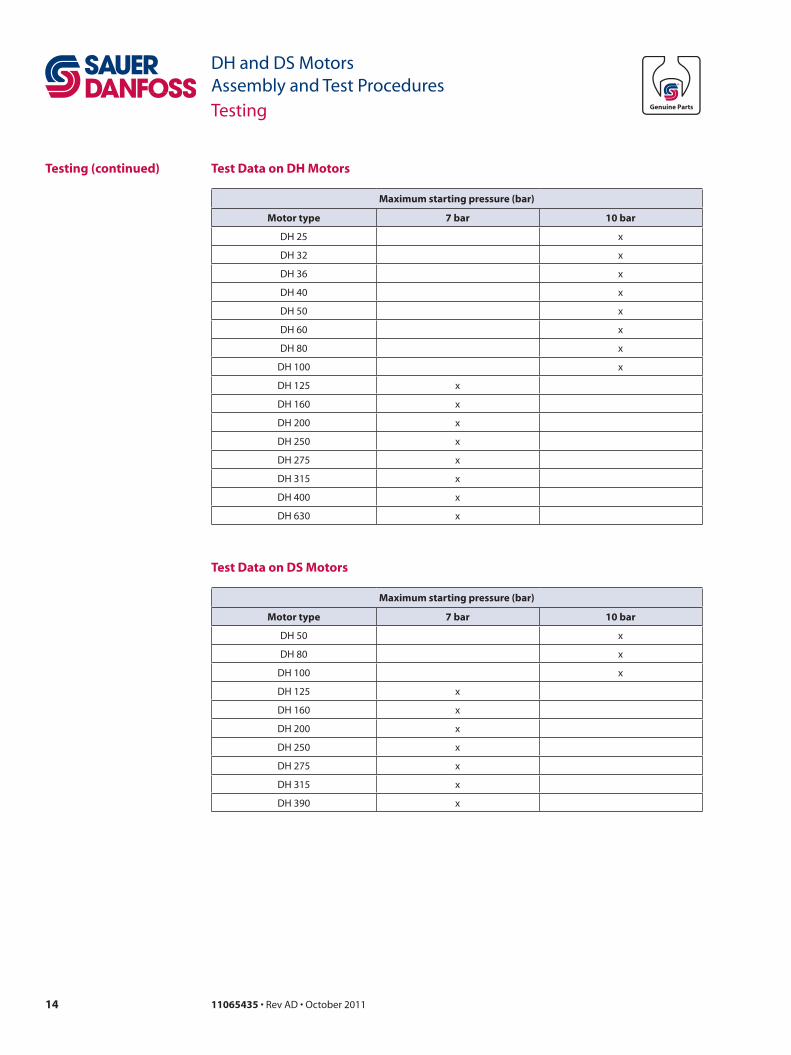
With the motor disengaged and no outside load on the output shaft, slowly raise the oil supply pressure until the motor starts. Then lower the differential pressure to the limit shown in the table below (7 or 10 bar [102 or 145 psi]). Check that the motor is still turning at this limit. If so the motor is good.
If the motor begins to turn below the specified pressure, the motor check is OK.
Starting Pressure
14 11065435 • Rev AD • October 2011
DH and DS MotorsAssembly and Test ProceduresTesting
Maximum starting pressure (bar)
Motor type 7 bar 10 bar
DH 25 x
DH 32 x
DH 36 x
DH 40 x
DH 50 x
DH 60 x
DH 80 x
DH 100 x
DH 125 x
DH 160 x
DH 200 x
DH 250 x
DH 275 x
DH 315 x
DH 400 x
DH 630 x
Testing (continued) Test Data on DH Motors
Maximum starting pressure (bar)
Motor type 7 bar 10 bar
DH 50 x
DH 80 x
DH 100 x
DH 125 x
DH 160 x
DH 200 x
DH 250 x
DH 275 x
DH 315 x
DH 390 x
Test Data on DS Motors
1511065435 • Rev AD • October 2011
DH and DS MotorsAssembly and Test ProceduresSchematic
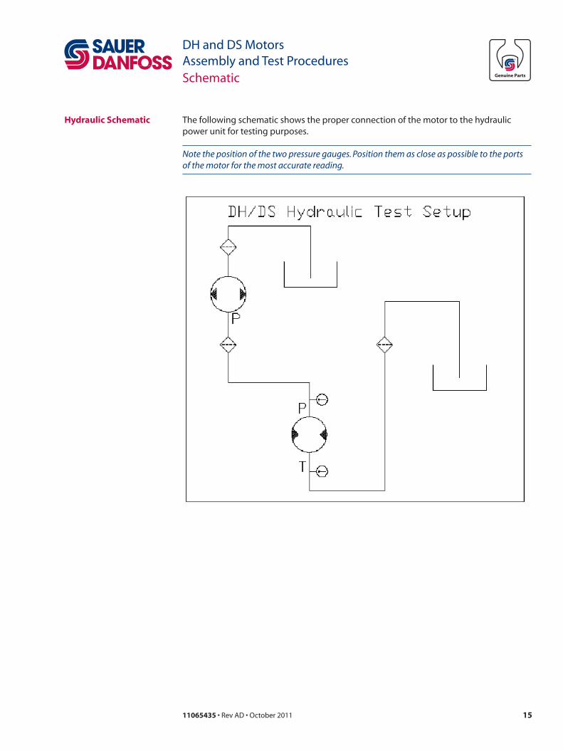
Hydraulic Schematic The following schematic shows the proper connection of the motor to the hydraulic power unit for testing purposes.
Note the position of the two pressure gauges. Position them as close as possible to the ports of the motor for the most accurate reading.
16 11065435 • Rev AD • October 2011
DH and DS MotorsAssembly and Test ProceduresMotor Identification
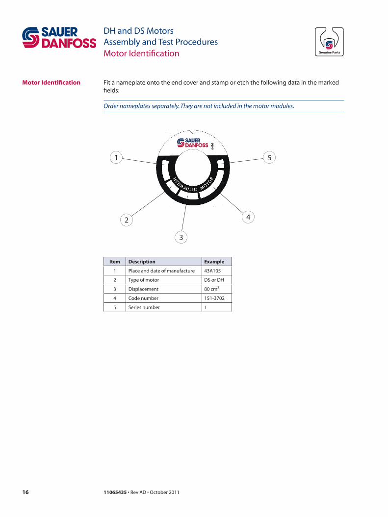
Motor Identification Fit a nameplate onto the end cover and stamp or etch the following data in the marked fields:
Order nameplates separately. They are not included in the motor modules.
1
2
3
4
5
Item Description Example
1 Place and date of manufacture 43A105
2 Type of motor DS or DH
3 Displacement 80 cm³
4 Code number 151-3702
5 Series number 1
1711065435 • Rev AD • October 2011
DH and DS MotorsAssembly and Test ProceduresAssembly Drawings
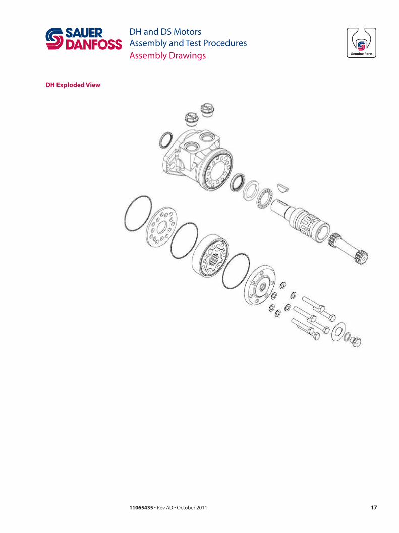
DH Exploded View
18 11065435 • Rev AD • October 2011
DH and DS MotorsAssembly and Test ProceduresAssembly Drawings
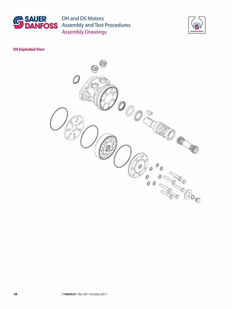
DS Exploded View
1911065435 • Rev AD • October 2011
DH and DS MotorsAssembly and Test ProceduresNotes

11065435 •Rev AD • October 2011
Local address:
Sauer-Danfoss GmbH & Co. OHGPostfach 2460, D-24531 NeumünsterKrokamp 35, D-24539 Neumünster, GermanyPhone: +49 4321 871 0Fax: +49 4321 871 122
Sauer-Danfoss ApSDK-6430 Nordborg, DenmarkPhone: +45 7488 4444Fax: +45 7488 4400
Sauer-Danfoss is a global manufacturer and supplier of high-quality hydraulic and electronic components. We specialize in providing state-of-the-art technology and solutions that excel in the harsh operating conditions of the mobile o� -highway market. Building on our extensive applications expertise, we work closely with our customers to ensure exceptional performance for a broad range of o� -highway vehicles.
We help OEMs around the world speed up system development, reduce costs and bring vehicles to market faster. Sauer-Danfoss – Your Strongest Partner in Mobile Hydraulics.
Go to www.sauer-danfoss.com for further product information.
Wherever o� -highway vehicles are at work, so is Sauer-Danfoss.
We o� er expert worldwide support for our customers, ensuring the best possible solutions for outstanding performance. And with an extensive network of Global Service Partners, we also provide comprehensive global service for all of our components.
Please contact the Sauer-Danfoss representative nearest you.
Products we o� er:
• Bent Axis Motors
• Closed Circuit Axial Piston Pumps and Motors
• Displays
• Electrohydraulic Power Steering
• Electrohydraulics
• Hydraulic Power Steering
• Integrated Systems
• Joysticks and Control Handles
• Microcontrollers and Software
• Open Circuit Axial Piston Pumps
• Orbital Motors
• PLUS+1™ GUIDE
• Proportional Valves
• Sensors
• Steering
• Transit Mixer Drives
Members of the Sauer-Danfoss Group:
Comatrolwww.comatrol.com
Schwarzmüller-Inverterwww.schwarzmueller-inverter.com
Turolla www.turollaocg.com
Hydro-Gear www.hydro-gear.com
Sauer-Danfoss-Daikinwww.sauer-danfoss-daikin.com
Sauer-Danfoss (US) Company2800 East 13th StreetAmes, IA 50010, USAPhone: +1 515 239 6000Fax: +1 515 239 6618
Sauer-Danfoss-Daikin LTD.Shin-Osaka TERASAKI 3rd Bldg. 6F1-5-28 Nishimiyahara, Yodogawa-kuOsaka 532-0004, JapanPhone: +81 6 6395 6066Fax: +81 6 6395 8585
w w w . s a u e r - d a n f o s s . c o m


![ceomadhyapradesh.nic.inceomadhyapradesh.nic.in/PollingStation2018_Upbandh_II_SR/A106.pdfernku dsUnzksa dh lwph ds izdk'ku dh lwpuk yksd izfrfuf/kRo vf/kfu;e] 1951 dh /kkjk 25 ds mica/kksa](https://img.pdfslide.net/doc/110x75/5e7de36c687d8312f2705a04/ernku-dsunzksa-dh-lwph-ds-izdkku-dh-lwpuk-yksd-izfrfufkro-vfkfue-1951-dh-kkjk.jpg)


![dh nqfu;k vkb,y~vks dh if=kdk · lnL; vkb,y~vks ds 179 lnL; ns'kksa dh 1]900 fjiksV~lZ tkaprs gSa rFkk 2]500 fVIif.k;ka Hkstrs gSaA 1964 ds ckn ls vuqlefFkZr le>kSrksa ds csgrj dk;kZUo;u](https://img.pdfslide.net/doc/110x75/5faf467b2fc3f93d6e6afeac/dh-nqfuk-vkbyvks-dh-if-lnl-vkbyvks-ds-179-lnl-nskksa-dh-1900-fjiksvlz.jpg)


![1- · Web view... gq, gSA tks/kiqj ds fuekZrk jko tks/kk ds iq= chdk us 1488 esa chdkusj dh LFkkiuk dh] dgk tkrk gS fd chdkusj ds bfrgkl esa gh xaxkuxj ftys dk bfrgkl fNik gSA orZeku](https://img.pdfslide.net/doc/110x75/5ae1d4cb7f8b9a0d7d8ba425/1-view-gq-gsa-tkskiqj-ds-fuekzrk-jko-tkskk-ds-iq-chdk-us-1488-esa-chdkusj.jpg)

![Qklhokn O;fV vFkZ’kkL=k ,oa Hkkjr dh vkfFkZd leL;k,a Economic.pdf · dh [kkst* j[kkA muds vuqlkj] ^^vFkZ’kkL=k jk"V“ksa ds Łku ds Lo:i rFkk dkj.kksa dh [kkst djrk gSA** blh](https://img.pdfslide.net/doc/110x75/5c90aaa409d3f2c8148bb817/qklhokn-ofv-vfkzkklk-oa-hkkjr-dh-vkffkzd-lelka-economicpdf-dh-kkst.jpg)


![bUæ nso] vk’kk jke] ds-ch Jh/kj] ujs’k dqekj] vkj-ds ... · 2- ck¡l dh c](https://img.pdfslide.net/doc/110x75/5f99a6ca50219e22c95fa25d/bu-nso-vkakk-jke-ds-ch-jhkj-ujsak-dqekj-vkj-ds-2-ckl-dh-c.jpg)


