Embed Size (px)
Citation preview
ENS7003R3 KO65 2011 1
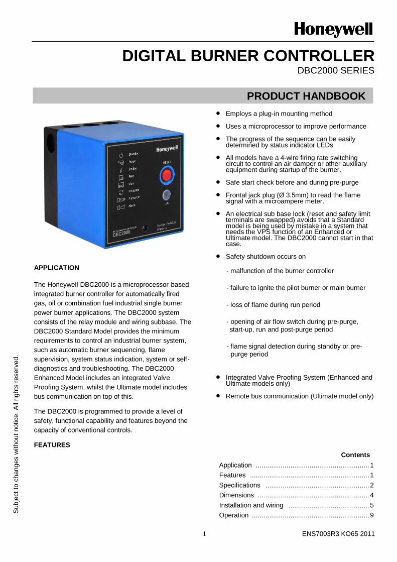
DIGITAL BURNER CONTROLLER DBC2000 SERIES
APPLICATION
The Honeywell DBC2000 is a microprocessor-based
integrated burner controller for automatically fired
gas, oil or combination fuel industrial single burner
power burner applications. The DBC2000 system
consists of the relay module and wiring subbase. The
DBC2000 Standard Model provides the minimum
requirements to control an industrial burner system,
such as automatic burner sequencing, flame
supervision, system status indication, system or self-
diagnostics and troubleshooting. The DBC2000
Enhanced Model includes an integrated Valve
Proofing System, whilst the Ultimate model includes
bus communication on top of this.
The DBC2000 is programmed to provide a level of
safety, functional capability and features beyond the
capacity of conventional controls.
FEATURES
Employs a plug-in mounting method
Uses a microprocessor to improve performance
The progress of the sequence can be easily determined by status indicator LEDs
All models have a 4-wire firing rate switching circuit to control an air damper or other auxiliary equipment during startup of the burner.
Safe start check before and during pre-purge
Frontal jack plug (Ø 3.5mm) to read the flame signal with a microampere meter.
An electrical sub base lock (reset and safety limit terminals are swapped) avoids that a Standard model is being used by mistake in a system that needs the VPS function of an Enhanced or Ultimate model. The DBC2000 cannot start in that case.
Safety shutdown occurs on
- malfunction of the burner controller
- failure to ignite the pilot burner or main burner
- loss of flame during run period
- opening of air flow switch during pre-purge, start-up, run and post-purge period
- flame signal detection during standby or pre-purge period
Integrated Valve Proofing System (Enhanced and
Ultimate models only)
Remote bus communication (Ultimate model only)
Contents
Application ........................................................... 1
Features .............................................................. 1
Specifications ...................................................... 2
Dimensions .......................................................... 4
Installation and wiring .......................................... 5
Operation ............................................................. 9
Subje
ct
to c
hanges w
ithout
notice.
All
rights
reserv
ed.
PRODUCT HANDBOOK
ENS7003R3 KO65 2011 2
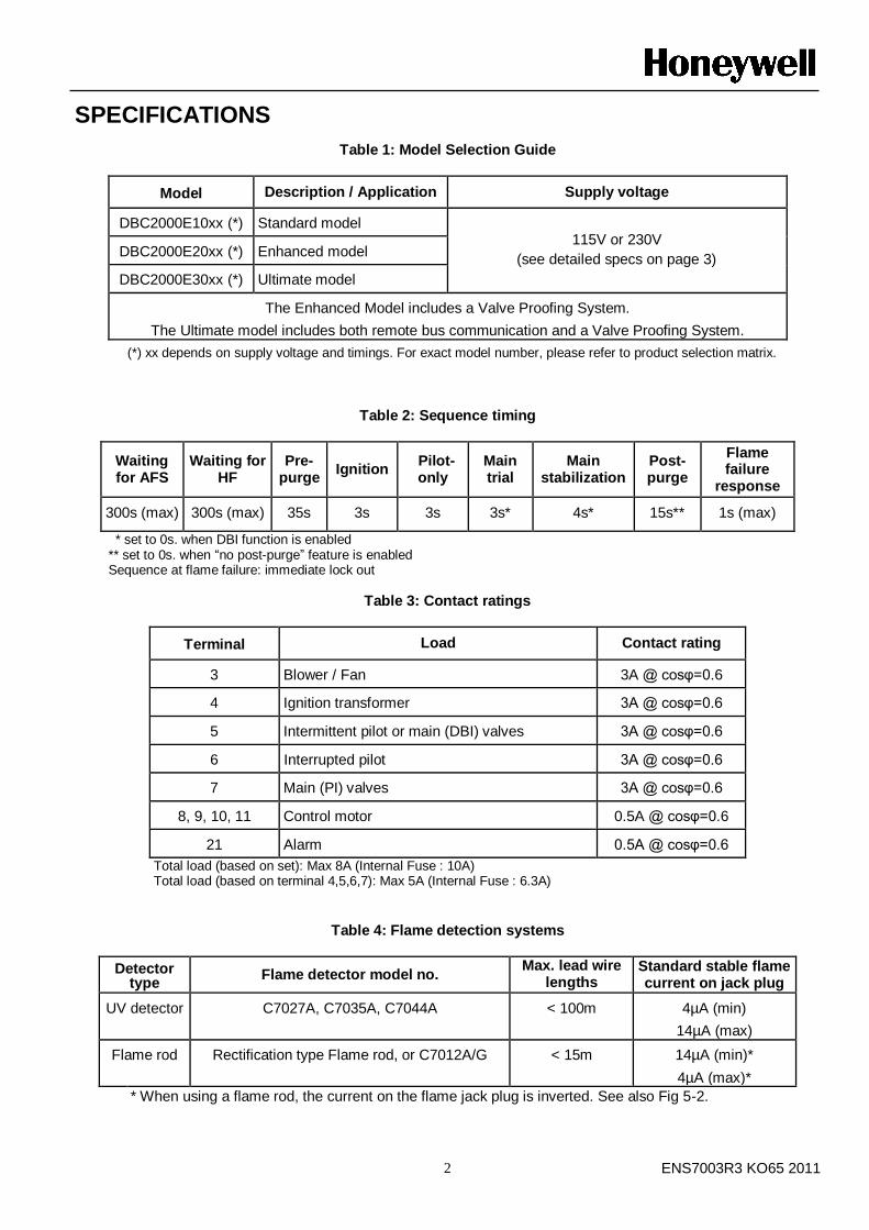
SPECIFICATIONS
Table 1: Model Selection Guide
Model Description / Application Supply voltage
DBC2000E10xx (*) Standard model 115V or 230V
(see detailed specs on page 3) DBC2000E20xx (*) Enhanced model
DBC2000E30xx (*) Ultimate model
The Enhanced Model includes a Valve Proofing System.
The Ultimate model includes both remote bus communication and a Valve Proofing System.
(*) xx depends on supply voltage and timings. For exact model number, please refer to product selection matrix.
Table 2: Sequence timing
Waiting for AFS
Waiting for HF
Pre-purge
Ignition Pilot-only
Main trial
Main stabilization
Post- purge
Flame failure
response
300s (max) 300s (max) 35s 3s 3s 3s* 4s* 15s** 1s (max)
* set to 0s. when DBI function is enabled ** set to 0s. when “no post-purge” feature is enabled Sequence at flame failure: immediate lock out
Table 3: Contact ratings
Terminal Load Contact rating
3 Blower / Fan 3A @ cosφ=0.6
4 Ignition transformer 3A @ cosφ=0.6
5 Intermittent pilot or main (DBI) valves 3A @ cosφ=0.6
6 Interrupted pilot 3A @ cosφ=0.6
7 Main (PI) valves 3A @ cosφ=0.6
8, 9, 10, 11 Control motor 0.5A @ cosφ=0.6
21 Alarm 0.5A @ cosφ=0.6
Total load (based on set): Max 8A (Internal Fuse : 10A) Total load (based on terminal 4,5,6,7): Max 5A (Internal Fuse : 6.3A)
Table 4: Flame detection systems
Detector type
Flame detector model no. Max. lead wire
lengths Standard stable flame current on jack plug
UV detector C7027A, C7035A, C7044A < 100m 4µA (min)
14µA (max)
Flame rod Rectification type Flame rod, or C7012A/G < 15m 14µA (min)*
4µA (max)*
* When using a flame rod, the current on the flame jack plug is inverted. See also Fig 5-2.
ENS7003R3 KO65 2011 3
Mains input: Supply voltage
220 to 240Vac -15% +10% 50/60Hz or
110 to 120Vac -15% +10% 50/60Hz
Allowable ambient Temperature & Humidity
-10 °C; +60°C
90% RH max. at 40°C (non-condensing)
Classification to EN298 (Chapter 4)
F/B/L/L/X/N
Where: F = Fan assisted B = Interrupted and Intermittent pilot capable L (1
st) = non-volatile lockout after flame loss
L (2nd
) = non-volatile lockout after flame loss final stage X = Fixed timings per model number N = Intermittent operation (non-self-check)
Approvals
CE certification to EN298:2003 (gas, UV & flame rod)
CE certification to EN230:2005 (oil, UV only)
Additional approvals:
Lloyds (planned)
EN746-2 compliant
PED (planned)
SIL2 (planned)
Apave (planned)
Power consumption
9VA
Protection class IP40
Mounting Plug-in mounting method using sub-base
Dimensions 103mm x 103mm x 124mm (W x D x H) incl. sub base
Status indicator LEDs - Standby
- Purge
- Ignition
- Pilot
- Main
- Modulate
- Flame On
- Alarm
The LEDs will shortly blink as soon as power is applied to
the DBC2000 and then as soon as there is a heat demand, indicate the burner sequence.
The LEDs are also used to indicate faults. For example, if
a loss of flame signal occurs during RUN, the LEDs for Alarm, Flame and Main will blink the fault code.
Jack plug
The flame signal can be measured using the jack
plug (Ø 3.5mm) on the front, using a microampere
meter. The measuring device must be capable of
reading microamperes between 2 and 15~20 µA.
CAUTION
Although the voltage on the jack plug is of low voltage,
it is not considered to be safe when touching the wires
connected to the jack plug, in case of a malfunction of
the device. Therefore avoid touching the lead wires to avoid an electrical shock.
Reset switch
When the DBC2000 is in lock out condition and the
alarm LED blinks, press reset button one time to
reset the DBC2000 and stop the alarm. If the heat
demand is still present, the DBC2000 will perform the
start sequence normally if the fault condition has been resolved, otherwise the lock out will repeat.
If during the lock out condition the DBC2000 is
deenergized and power is reapplied afterwards, the
DBC2000 will remain in lock out (non-volatile lock out).
A remote reset push button switch can be connected
between terminals 15 and 19 (Standard Model) or
between terminals 15 and 18 (Enhanced and
Ultimate Models). The functionality of the remote
reset is the same as the red push button on the front of the device, with one exception:.
The remote reset may occur only 5 times during 15
minutes of operation, while the internal reset buton is unlimited.
Remote communication - Communication protocol: Profibus or Modbus
- Availability of:
Sequence status
Fault information
Flame signal strength
Remote reset (max 5x per 15mins)
Remote heat demand
Firing rate high/low control
- Transmission speed: 9600bps
- Interface type: RS485 (M+, M-, COM)
- Address select: 1~99 encoder switch
CAUTION Although the voltage on the communication lead
wires is of low voltage, it is not considered to be safe
when touching these wires, in case of a malfunction
of the device. Therefore avoid touching the
communication lead wires to avoid an electrical
shock.
ENS7003R3 KO65 2011 4
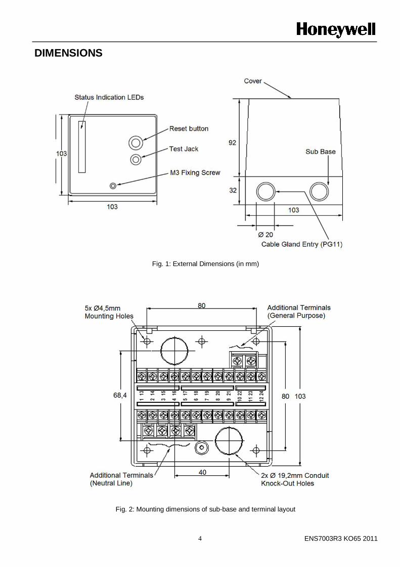
DIMENSIONS
Fig. 1: External Dimensions (in mm)
Fig. 2: Mounting dimensions of sub-base and terminal layout
ENS7003R3 KO65 2011 5
INSTALLATION AND WIRING
CAUTION
INSTALLATION
When Installing this Product…
1. Read these instructions carefully. Failure to
follow them could damage the product or cause a hazardous condition.
2. Check the ratings given in the instructions and
marked on the product to make sure the product is suitable for the application.
3. Installer must be a trained, experienced, flame safeguard service technician.
4. After installation is completed, check out the
product operation as provided in these instructions.
WARNING Fire or Explosion Hazard.
Can cause property damage,
severe injury, or death.
Carefully follow safety requirements when installing a
burner control.
CAUTION Electrical Shock Hazard or Equipment/
Control Damage.
Disconnect power supply before beginning
installation, to avoid electrical shock or equipment damage..
IMPORTANT
1. Wiring connections for the relay modules are
unique; refer to Fig. 3-2 or the appropriate Specifications for individual subbase wiring.
2. Wiring must comply with all applicable codes, ordinances and regulations.
3. Wiring must comply with NEC Class 1
(Line Voltage) wiring.
4. Loads connected to the DBC2000E must not
exceed those listed on the relay module label or the Specifications; see Table 3.
5. Limits and interlocks must be rated to
simultaneously carry and break current to the ignition transformer and fuel valve(s).
6. All external timers must be listed or component
recognized by authorities who have proper jurisdiction.
7. For on-off gas-fired systems, some authorities
who have jurisdiction prohibit the wiring of any
limit or operating contacts in series between the
flame safeguard control and the main fuel valve(s).
8. Two UV flame detectors can be connected in parallel.
9. This equipment generates, uses and can radiate
radio frequency energy and, if not installed and
used in accordance with the instructions, can
cause interference with radio communications. It
has been tested and found to comply with the
limits for a Class B computing device of Part 15
of FCC rules, which are designed to provide
reasonable protection against such interference
when operated in an industrial or commercial
environment. Operation of this equipment in a
residential area can cause interference, in which
case, the users, at their own expense, may be
required to take whatever measures are required to correct this interference.
10. This digital apparatus complies with the requirements as stated in the EN298:2003.
11. Do not install the Burner Controller under any circumstances in the following locations.
① Where chemicals or corrosive gases are
present, such as ammonia, sulfur, chlorine, ethylene compounds, acids, etc.
② Install the relay module where the relative
humidity never reaches the saturation point.
The relay module is designed to operate in a
maximum 85% relative humidity continuous,
noncondensing, moisture environment.
Condensing moisture can cause a safety shutdown or damage the device.
③ Where temperatures exceed the maximum specification for this device.
④ Where excessive continuous vibration exists.
12. Do not bundle power wiring and high voltage
ignition cable with the flame detector wiring, or
run them in parallel within the same conduit.
High voltage cables must be kept separated at least 10 cm from the Burner Controller.
13. Use proper grounding work in accordance with
the engineering standards for electrical equipment
14. Connect the high voltage cable of the ignition
transformer properly to the ignition electrode. A
poor connection can cause an electrical shock or
damage the equipment. Additionally the ignition
transformer must be properly grounded according the standards.
ENS7003R3 KO65 2011 6
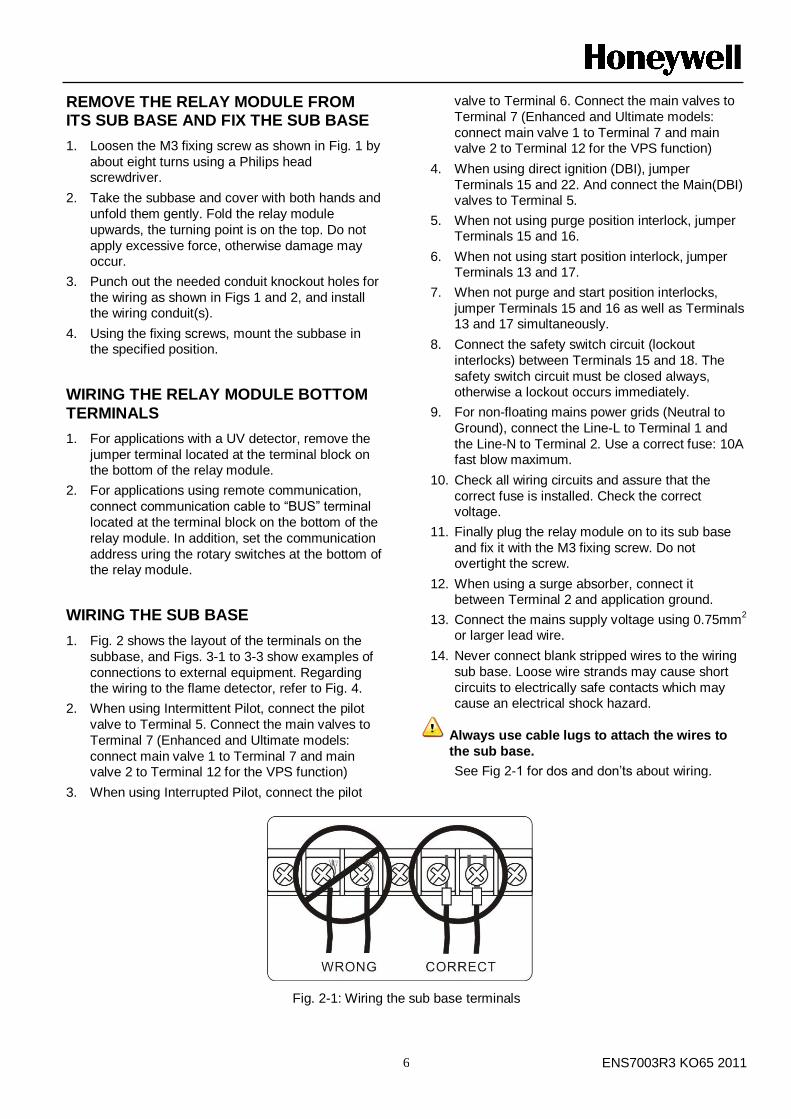
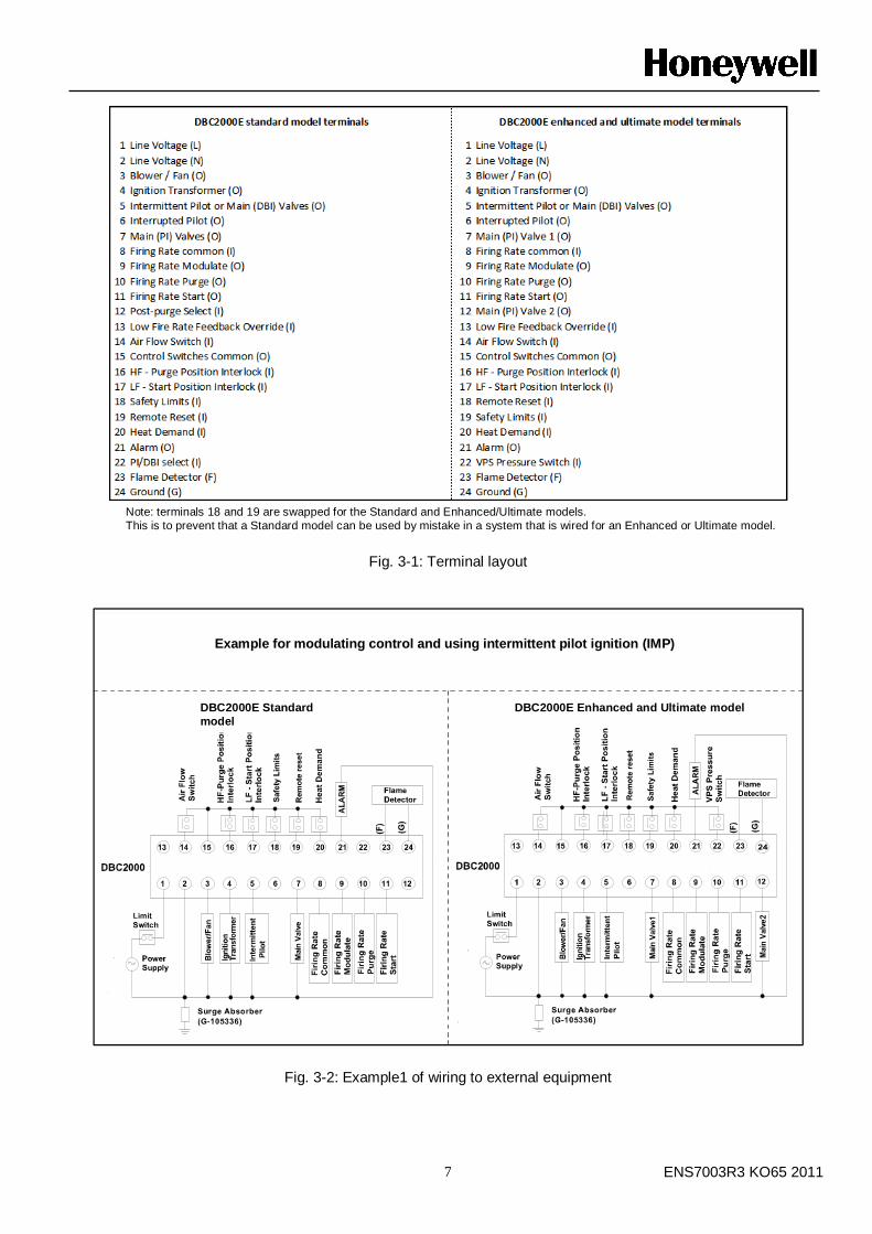
REMOVE THE RELAY MODULE FROM ITS SUB BASE AND FIX THE SUB BASE
1. Loosen the M3 fixing screw as shown in Fig. 1 by
about eight turns using a Philips head screwdriver.
2. Take the subbase and cover with both hands and
unfold them gently. Fold the relay module
upwards, the turning point is on the top. Do not
apply excessive force, otherwise damage may occur.
3. Punch out the needed conduit knockout holes for
the wiring as shown in Figs 1 and 2, and install the wiring conduit(s).
4. Using the fixing screws, mount the subbase in the specified position.
WIRING THE RELAY MODULE BOTTOM
TERMINALS
1. For applications with a UV detector, remove the
jumper terminal located at the terminal block on the bottom of the relay module.
2. For applications using remote communication,
connect communication cable to “BUS” terminal
located at the terminal block on the bottom of the
relay module. In addition, set the communication
address uring the rotary switches at the bottom of the relay module.
WIRING THE SUB BASE
1. Fig. 2 shows the layout of the terminals on the
subbase, and Figs. 3-1 to 3-3 show examples of
connections to external equipment. Regarding the wiring to the flame detector, refer to Fig. 4.
2. When using Intermittent Pilot, connect the pilot
valve to Terminal 5. Connect the main valves to
Terminal 7 (Enhanced and Ultimate models:
connect main valve 1 to Terminal 7 and main valve 2 to Terminal 12 for the VPS function)
3. When using Interrupted Pilot, connect the pilot
valve to Terminal 6. Connect the main valves to
Terminal 7 (Enhanced and Ultimate models:
connect main valve 1 to Terminal 7 and main valve 2 to Terminal 12 for the VPS function)
4. When using direct ignition (DBI), jumper
Terminals 15 and 22. And connect the Main(DBI) valves to Terminal 5.
5. When not using purge position interlock, jumper Terminals 15 and 16.
6. When not using start position interlock, jumper Terminals 13 and 17.
7. When not purge and start position interlocks,
jumper Terminals 15 and 16 as well as Terminals 13 and 17 simultaneously.
8. Connect the safety switch circuit (lockout
interlocks) between Terminals 15 and 18. The
safety switch circuit must be closed always, otherwise a lockout occurs immediately.
9. For non-floating mains power grids (Neutral to
Ground), connect the Line-L to Terminal 1 and
the Line-N to Terminal 2. Use a correct fuse: 10A fast blow maximum.
10. Check all wiring circuits and assure that the
correct fuse is installed. Check the correct voltage.
11. Finally plug the relay module on to its sub base
and fix it with the M3 fixing screw. Do not overtight the screw.
12. When using a surge absorber, connect it between Terminal 2 and application ground.
13. Connect the mains supply voltage using 0.75mm2
or larger lead wire.
14. Never connect blank stripped wires to the wiring
sub base. Loose wire strands may cause short
circuits to electrically safe contacts which may cause an electrical shock hazard.
Always use cable lugs to attach the wires to
the sub base.
See Fig 2-1 for dos and don‟ts about wiring.
Fig. 2-1: Wiring the sub base terminals
ENS7003R3 KO65 2011 7
Note: terminals 18 and 19 are swapped for the Standard and Enhanced/Ultimate models.
This is to prevent that a Standard model can be used by mistake in a system that is wired for an Enhanced or Ultimate model.
Fig. 3-1: Terminal layout
Fig. 3-2: Example1 of wiring to external equipment
DBC2000E Standard
model
DBC2000E Enhanced and Ultimate model
Example for modulating control and using intermittent pilot ignition (IMP)
ENS7003R3 KO65 2011 8
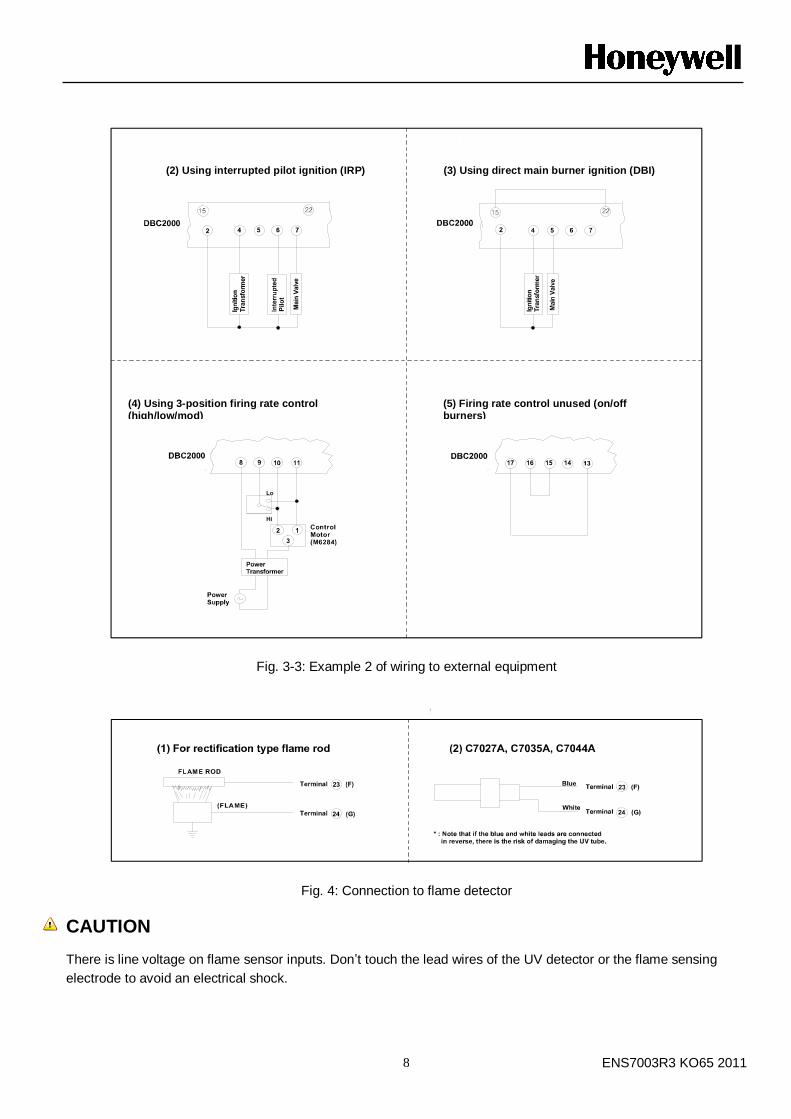
Fig. 3-3: Example 2 of wiring to external equipment
Fig. 4: Connection to flame detector
CAUTION
There is line voltage on flame sensor inputs. Don‟t touch the lead wires of the UV detector or the flame sensing
electrode to avoid an electrical shock.
(2) Using interrupted pilot ignition (IRP) (3) Using direct main burner ignition (DBI)
(5) Firing rate control unused (on/off burners)
(4) Using 3-position firing rate control (high/low/mod)

ENS7003R3 KO65 2011 9
OPERATION
1. NORMAL OPERATION
Power SW and Controllers Operation of DBC2000 and device Indicator LED *
Power SW ON,
Limit SW ON
The power supply voltage is applied across Terminal 1 and 2. When no flame signal is present, the combustion airflow switch is opened (T14=OFF) and safety lockout circuit is closed (ON), it is possible to start.
●○○○○○○○
Controller ON The blower is energized (T3). Firing rate goes to PURGE position. Air flow switch closes (T14=ON) as soon as air flow is present.
●●○○○○○○
The pre-purge timer starts counting as soon as PURGE interlock is closed (T16=ON).
After the completion of pre-purge timing, firing rate goes to START position.
The ignition wait timer starts counting as soon as the START position interlock is closed (T17=ON).
After completion of the ignition wait timing, the Ignition sequence starts. The Ignition transformer is energized. The Intermittent and Interrupted pilot valve outputs are energized (T5 and T6).
●○●○○○●○
When a flame is detected after the ignition trial has ended (Safety1), the pilot stabilization time starts.
●○○●○○●○
After completion of the pilot-stabilization time, the Main valves are energized (T7=ON). Note: Enhanced Model: also (T12=ON).
The Main trial for ignition takes place (Safety2).
●○○○●○●○
After completion of the main trial time, Interrupted pilot valve is deenergized (T5=OFF). The Main stabilization time starts.
●○○○●○●○
After completion of the main stabilization time, the firing rate goes to modulation position and releases control to an external modulation device.
●○○○○●●○
Controller OFF The intermittent pilot valve and main valves are deenergized (T6=OFF and T7=OFF). Note: Enhanced Model: also (T12=OFF). Firing rate moves to PURGE position.
The post-purge timing takes place.
●●○○○○○○
After the completion of the postpurge time, the blower is deenergized and firing rate moves to START position.
●○○○○○○○
After the air flow switch goes OFF, DBC2000E returns to the STANDBY condition, waiting for the next heat demand.
* For LED indication, ○ means „off‟, ● means „illuminated‟, ◐means „blinking‟.
* The LEDs are arranged in the following order: Standby, Purge, Ignition, Pilot, Main, Modulate, Flame and Alarm at the left front side of the DBC2000.
ENS7003R3 KO65 2011 10
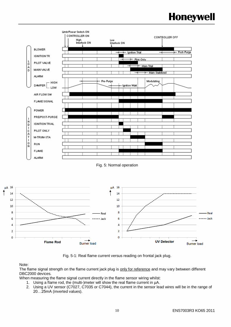
Fig. 5: Normal operation
Fig. 5-1: Real flame current versus reading on frontal jack plug. Note: The flame signal strength on the flame current jack plug is only for reference and may vary between different DBC2000 devices. When measuring the flame signal current directly in the flame sensor wiring whilst:
1. Using a flame rod, the (multi-)meter will show the real flame current in µA. 2. Using a UV sensor (C7027, C7035 or C7044), the current in the sensor lead wires will be in the range of
20…25mA (inverted values).
ENS7003R3 KO65 2011 11
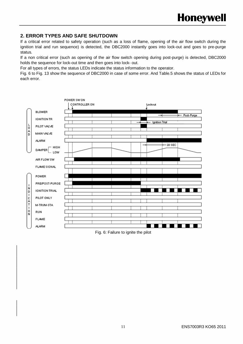
2. ERROR TYPES AND SAFE SHUTDOWN If a critical error related to safety operation (such as a loss of flame, opening of the air flow switch during the
ignition trial and run sequence) is detected, the DBC2000 instantly goes into lock-out and goes to pre-purge
status.
If a non critical error (such as opening of the air flow switch opening during post-purge) is detected, DBC2000
holds the sequence for lock-out time and then goes into lock- out.
For all types of errors, the status LEDs indicate the status information to the operator.
Fig. 6 to Fig. 13 show the sequence of DBC2000 in case of some error. And Table.5 shows the status of LEDs for
each error.
Fig. 6: Failure to ignite the pilot
ENS7003R3 KO65 2011 12
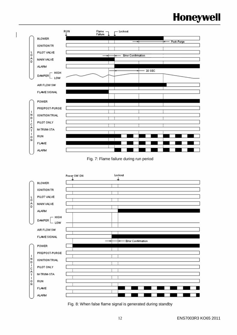
Fig. 7: Flame failure during run period
Fig. 8: When false flame signal is generated during standby
ENS7003R3 KO65 2011 13
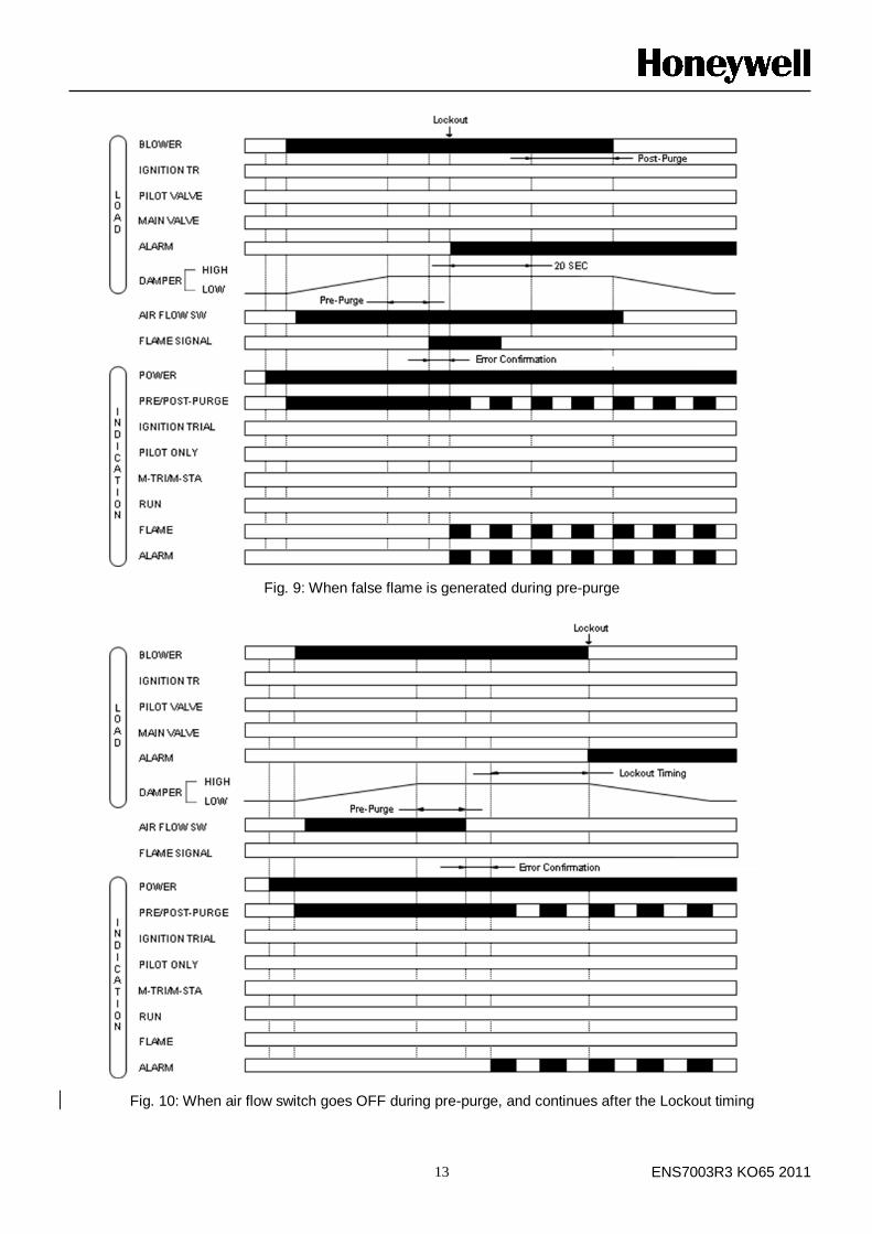
Fig. 9: When false flame is generated during pre-purge
Fig. 10: When air flow switch goes OFF during pre-purge, and continues after the Lockout timing
ENS7003R3 KO65 2011 14
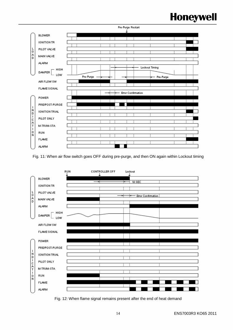
Fig. 11: When air flow switch goes OFF during pre-purge, and then ON again within Lockout timing
Fig. 12: When flame signal remains present after the end of heat demand
ENS7003R3 KO65 2011 15
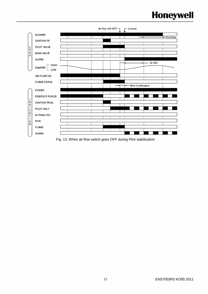
Fig. 13: When air flow switch goes OFF during Pilot stabilization
ENS7003R3 KO65 2011 16
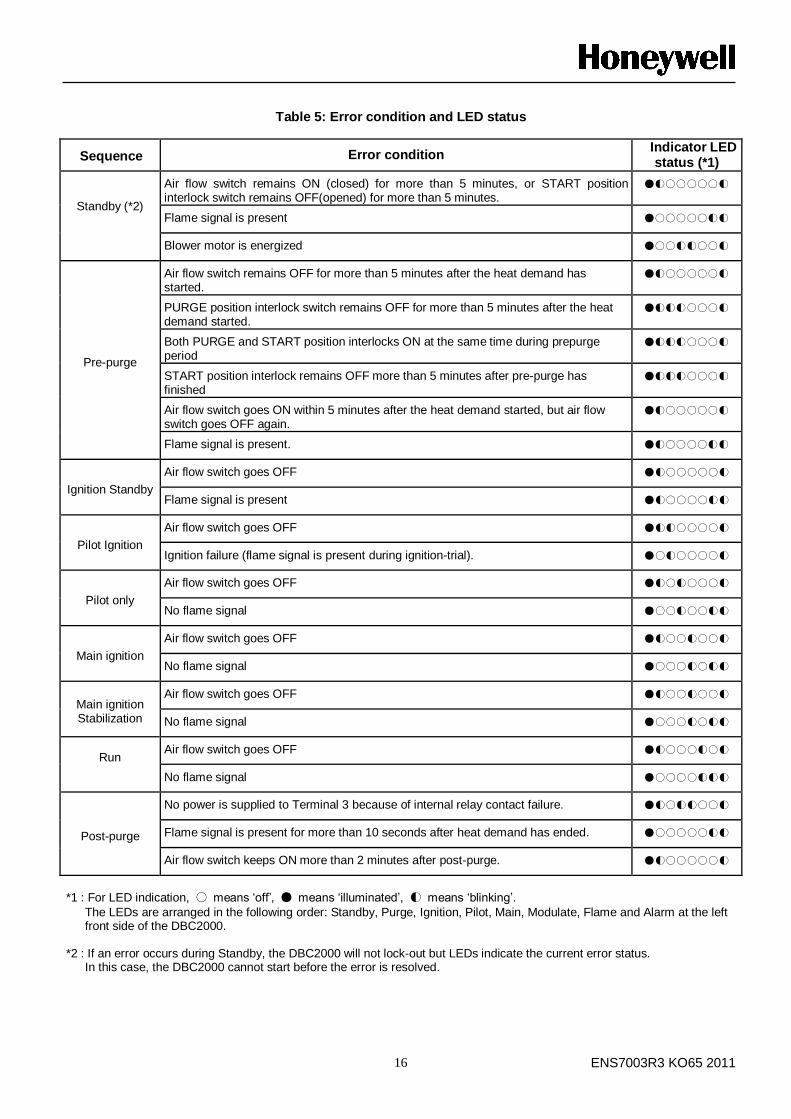
Table 5: Error condition and LED status
Sequence Error condition Indicator LED status (*1)
Standby (*2)
Air flow switch remains ON (closed) for more than 5 minutes, or START position interlock switch remains OFF(opened) for more than 5 minutes.
●◐○○○○○◐
Flame signal is present ●○○○○○◐◐
Blower motor is energized ●○○◐◐○○◐
Pre-purge
Air flow switch remains OFF for more than 5 minutes after the heat demand has started.
●◐○○○○○◐
PURGE position interlock switch remains OFF for more than 5 minutes after the heat demand started.
●◐◐◐○○○◐
Both PURGE and START position interlocks ON at the same time during prepurge period
●◐◐◐○○○◐
START position interlock remains OFF more than 5 minutes after pre-purge has finished
●◐◐◐○○○◐
Air flow switch goes ON within 5 minutes after the heat demand started, but air flow switch goes OFF again.
●◐○○○○○◐
Flame signal is present. ●◐○○○○◐◐
Ignition Standby
Air flow switch goes OFF ●◐○○○○○◐
Flame signal is present ●◐○○○○◐◐
Pilot Ignition
Air flow switch goes OFF ●◐◐○○○○◐
Ignition failure (flame signal is present during ignition-trial). ●○◐○○○○◐
Pilot only
Air flow switch goes OFF ●◐○◐○○○◐
No flame signal ●○○◐○○◐◐
Main ignition
Air flow switch goes OFF ●◐○○◐○○◐
No flame signal ●○○○◐○◐◐
Main ignition Stabilization
Air flow switch goes OFF ●◐○○◐○○◐
No flame signal ●○○○◐○◐◐
Run
Air flow switch goes OFF ●◐○○○◐○◐
No flame signal ●○○○○◐◐◐
Post-purge
No power is supplied to Terminal 3 because of internal relay contact failure. ●◐○◐◐○○◐
Flame signal is present for more than 10 seconds after heat demand has ended. ●○○○○○◐◐
Air flow switch keeps ON more than 2 minutes after post-purge. ●◐○○○○○◐
*1 : For LED indication, ○ means „off‟, ● means „illuminated‟, ◐ means „blinking‟.
The LEDs are arranged in the following order: Standby, Purge, Ignition, Pilot, Main, Modulate, Flame and Alarm at the left front side of the DBC2000.
*2 : If an error occurs during Standby, the DBC2000 will not lock-out but LEDs indicate the current error status.
In this case, the DBC2000 cannot start before the error is resolved.


![ACATacat.or.th/download/acat_or_th/journal-4/04 - 04.pdf · APmin APmax Appendix G [1] AP APmax Overpressure Relief Damper Damper 12 Relief Damper Relief Damper (Vent) Fire Damper](https://img.pdfslide.net/doc/110x75/5f7cb481641db55595223717/-04pdf-apmin-apmax-appendix-g-1-ap-apmax-overpressure-relief-damper-damper.jpg)