Embed Size (px)
Citation preview
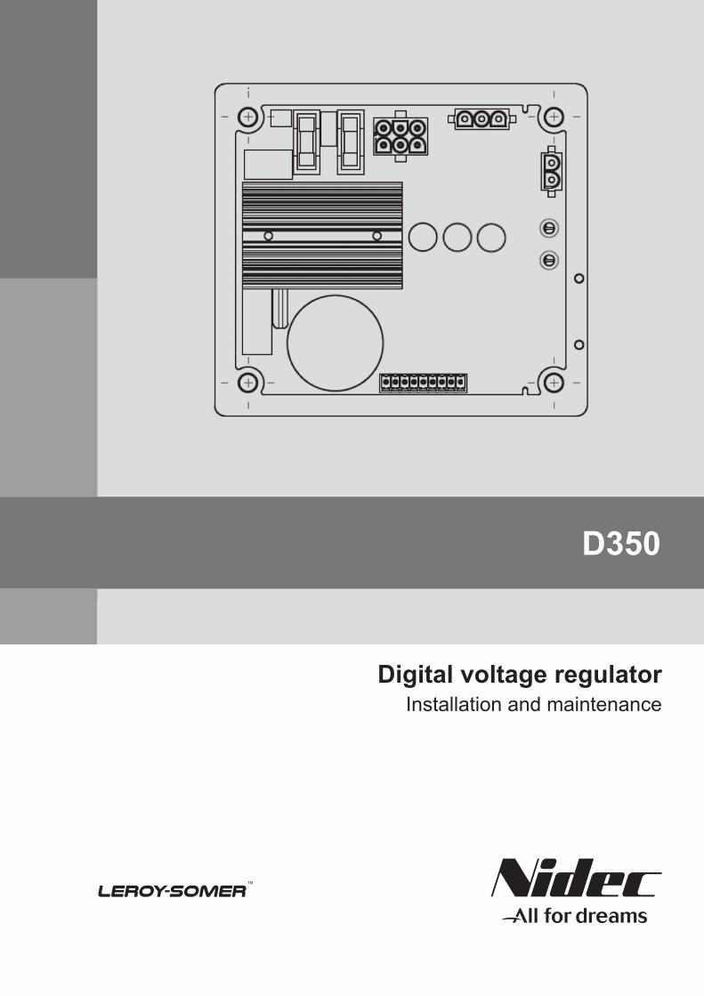
D350
Digital voltage regulatorInstallation and maintenance
Electric Power Generation Installation and maintenance
Digital voltage regulator D350
SAFETY MEASURES
Before using your machine for the first time, it is important to read the whole of this installation and maintenance manual.
All necessary operations and interventions on this machine must be performed by a qualified technician.
Our technical support service will be pleased to provide any additional information you may require.
The various operations described in this manual are accompanied by recommendations or symbols to alert the user to potential risks of accidents. It is vital that you understand and take notice of the fol-lowing warning symbols.
Warning symbol for an operation capable of damaging or destroying the machine or surrounding equipment.
Warning symbol for general danger to personnel.
Warning symbol for electrical danger to personnel.
All servicing or repair operations performed on the AVR should be undertaken by personnel trained in the commissioning, servicing and maintenance of electrical and mechanical com-ponents.
When the generator is driven at a frequency below 28 Hz for more than 30 seconds with an analogue AVR, its AC power supply must be disconnected.
WARNINGThis AVR can be incorporated in a EC-marked machine.This manual is to be given to the end user.
© - We reserve the right to modify the characteristics of this product at any time in order to incorporate the latest technological developments. The information contained in this document may therefore be changed without notice.
This document may not be reproduced in any form without prior authorisation.All brands and models have been registered and patents applied for.
WARNING
This manual concerns the alternator AVR which you have just purchased.We wish to draw your attention to the contents of this maintenance manual.
5611 en - 2019.05 / d
Electric Power Generation Installation and maintenance 5611 en - 2019.05 / d
Digital voltage regulator D350
3
Table of content
1. General Instructions .............................................................................................................................................. 5
1.1. Identity sheet................................................................................................................................................... 5 1.2. General Presentation..................................................................................................................................... 5
1.2.1. The D350 AVR ........................................................................................................................................ 5 1.2.2. NFLink™ configuration module ............................................................................................................ 6
1.3. Technical characteristics............................................................................................................................... 7 1.4. D350 AVR Dimensions ................................................................................................................................. 9 1.5. D350 AVR and NFLink™ Dimensions ...................................................................................................... 10 1.6. Mounting ........................................................................................................................................................ 11 1.7. Wiring ............................................................................................................................................................. 11
1.7.1. Alternator voltage measurement: ....................................................................................................... 11 1.7.2. Inputs/outputs ........................................................................................................................................ 12 1.7.3. Power supply and excitation ............................................................................................................... 14 1.7.4. Alternator current measurement (parallel operation CT):............................................................... 16
1.8. Wiring precautions ....................................................................................................................................... 16
2. Operations Instructions....................................................................................................................................... 18
2.1. Description of manual controls and signaling .......................................................................................... 18 2.1.1. The potentiometers............................................................................................................................... 18 2.1.2. The LED ................................................................................................................................................. 18
2.2. Description of the operating modes .......................................................................................................... 19
3. Setting instructions .............................................................................................................................................. 21
3.1. PC Software .................................................................................................................................................. 21 3.1.1. Software installation ............................................................................................................................. 21 3.1.2. Different access levels of Easyreg Advanced .................................................................................. 23 3.1.3. Description of the banner and tabs .................................................................................................... 24 3.1.4. Communication with the D350 ............................................................................................................ 26 3.1.5. “Configuration” window ........................................................................................................................ 27 3.1.6. Create a new quick configuration ....................................................................................................... 30
Step 1: Selection of the alternator type ...................................................................................... 30 Step 2: Definition of the alternator features .............................................................................. 31 Step 3: Wiring................................................................................................................................. 31 Step 4: Regulation mode selection ............................................................................................. 32 Step 5: Configuration upload ....................................................................................................... 33
3.1.7. Create a new configuration in custom mode .................................................................................... 33 Step 1: Description of the alternator ........................................................................................... 34 Step 2: AVR wiring ........................................................................................................................ 35 Step 3: Definition of the over excitation limit ............................................................................. 36 Step 4: Definition of stator current monitoring .......................................................................... 37 Step 5: Definition of the protections ........................................................................................... 37 Step 6a: Setting of the voltage soft start .................................................................................... 40 Step 6b: Voltage regulation ......................................................................................................... 41 Step 6c: Regulation of the field current (Manual mode).......................................................... 47 Step 7: Setting the PID gains ...................................................................................................... 49 Step 8: Inputs and outputs management ................................................................................ 50 Step 9: Log Event ........................................................................................................................ 51 Step 10: The Second Configuration ......................................................................................... 52
Electric Power Generation Installation and maintenance 5611 en - 2019.05 / d
Digital voltage regulator D350
4
3.1.8. “Oscilloscope” window ......................................................................................................................... 53 Curves ............................................................................................................................................. 53 Trigger ............................................................................................................................................. 55 Cursors ............................................................................................................................................ 56 Transient test ................................................................................................................................. 57 Open a curve or an oscilloscope display configuration ........................................................... 58 Save a curve or an oscilloscope display configuration............................................................ 58 Change the plotting area background ........................................................................................ 58
3.1.9. “Monitor” window................................................................................................................................... 59 Display units ................................................................................................................................... 59 Graph............................................................................................................................................... 60 Gauges ............................................................................................................................................ 60 Change the size of an object ....................................................................................................... 61 Delete an object ............................................................................................................................. 62 Save a monitor configuration ....................................................................................................... 62 Open a monitor configuration ...................................................................................................... 62
3.2. Operations as analogue AVR .................................................................................................................... 63 3.2.1. Voltage setting....................................................................................................................................... 63 3.2.2. Stability setting ...................................................................................................................................... 64 3.2.3. Droop compensation ............................................................................................................................ 64 3.2.4. Switching 50/60Hz ................................................................................................................................ 64
3.3. Tips and tricks............................................................................................................................................... 65 3.4. Comparison window .................................................................................................................................... 65
4. APPENDICES ...................................................................................................................................................... 67
4.1. Vector permutations..................................................................................................................................... 67 4.2. Regulation modes prioritization ................................................................................................................. 68 4.3. Electrical diagrams....................................................................................................................................... 69
4.3.1. SHUNT ................................................................................................................................................... 69 4.3.2. AREP ...................................................................................................................................................... 70 4.3.3. PMG ........................................................................................................................................................ 71
4.4. Faults trouble shouting ................................................................................................................................ 72 4.4.1. No Voltage ............................................................................................................................................. 72 4.4.2. Voltage too low ...................................................................................................................................... 73 4.4.3. Voltage unstable ................................................................................................................................... 74 4.4.4. Important voltage drop on load ........................................................................................................... 75 4.4.5. Time response too long ....................................................................................................................... 76
Electric Power Generation Installation and maintenance 5611 en - 2019.05 / d
Digital voltage regulator D350
5
1. General Instructions
1.1. Identity sheet
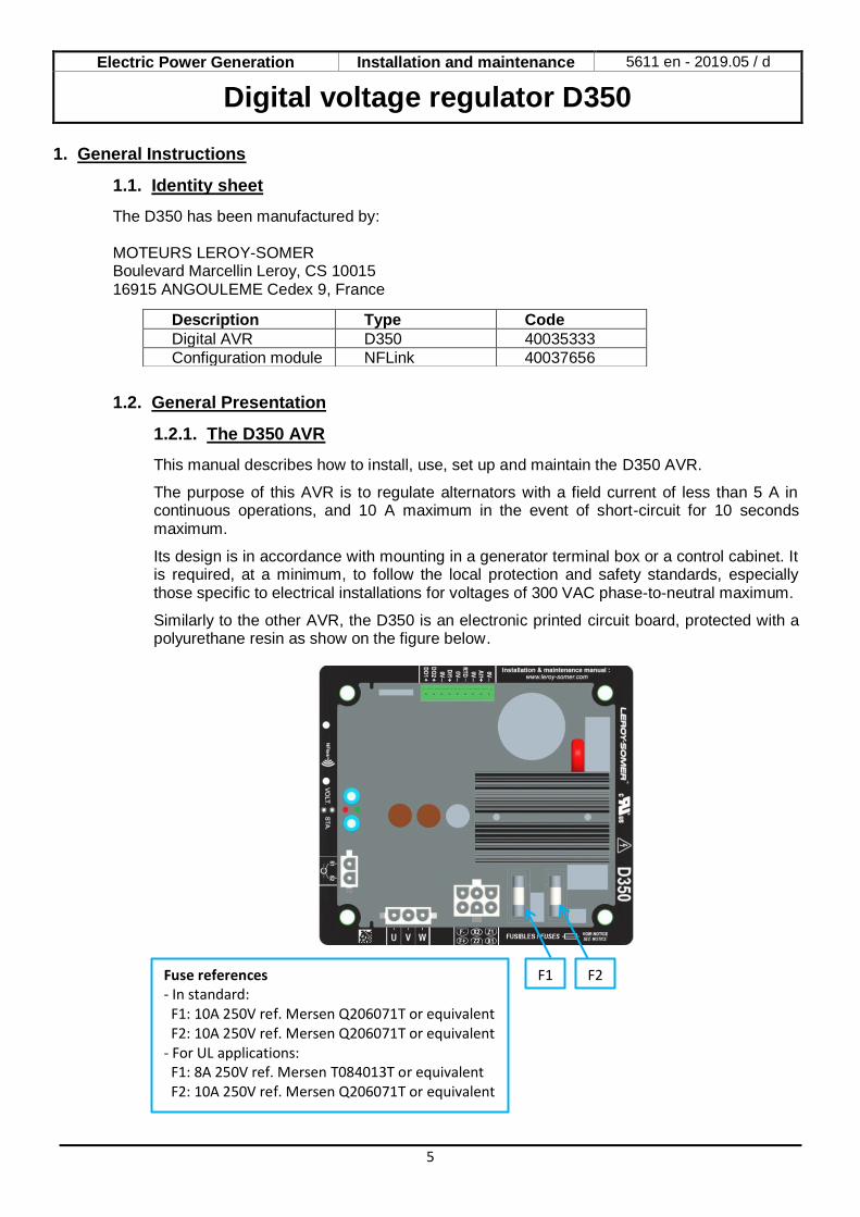
The D350 has been manufactured by: MOTEURS LEROY-SOMER Boulevard Marcellin Leroy, CS 10015 16915 ANGOULEME Cedex 9, France
1.2. General Presentation
1.2.1. The D350 AVR
This manual describes how to install, use, set up and maintain the D350 AVR. The purpose of this AVR is to regulate alternators with a field current of less than 5 A in continuous operations, and 10 A maximum in the event of short-circuit for 10 seconds maximum. Its design is in accordance with mounting in a generator terminal box or a control cabinet. It is required, at a minimum, to follow the local protection and safety standards, especially those specific to electrical installations for voltages of 300 VAC phase-to-neutral maximum. Similarly to the other AVR, the D350 is an electronic printed circuit board, protected with a polyurethane resin as show on the figure below.
Description Type Code
Digital AVR D350 40035333
Configuration module NFLink 40037656
F2 F1 Fuse references - In standard: F1: 10A 250V ref. Mersen Q206071T or equivalent F2: 10A 250V ref. Mersen Q206071T or equivalent - For UL applications: F1: 8A 250V ref. Mersen T084013T or equivalent F2: 10A 250V ref. Mersen Q206071T or equivalent
Electric Power Generation Installation and maintenance 5611 en - 2019.05 / d
Digital voltage regulator D350
6
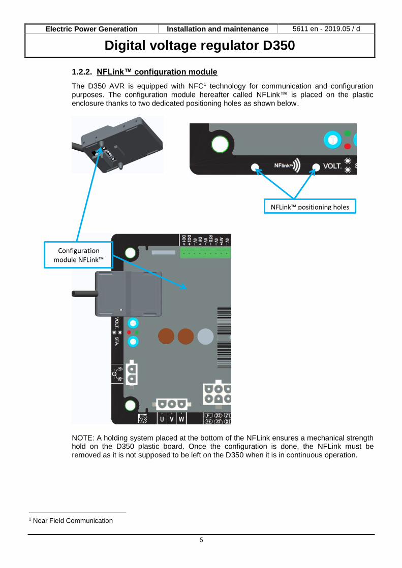
1.2.2. NFLink™ configuration module
The D350 AVR is equipped with NFC1 technology for communication and configuration purposes. The configuration module hereafter called NFLink™ is placed on the plastic enclosure thanks to two dedicated positioning holes as shown below.
NOTE: A holding system placed at the bottom of the NFLink ensures a mechanical strength hold on the D350 plastic board. Once the configuration is done, the NFLink must be removed as it is not supposed to be left on the D350 when it is in continuous operation.
1 Near Field Communication
NFLink™ positioning holes
Configuration module NFLink™
Electric Power Generation Installation and maintenance 5611 en - 2019.05 / d
Digital voltage regulator D350
7
1.3. Technical characteristics
The D350 AVR is a digital voltage regulator used to control the alternator from the field current or the output voltage regulation loops. • Voltage regulation:
• With or without reactive droop compensation droop to allow parallel machine operation.
• With or without line droop compensation.2 • Regulation of the field current, or manual mode, which allows direct control of the field
current value. The D350 can also be used to: • Adjust the reference for the regulation mode in progress, using an analogue input (0-10V
and potentiometer) • Monitoring of temperature sensor (Pt100 or CTP) • Limit the minimum field current delivered to the exciter field • Monitoring of the maximum stator current limit • Loss of voltage sensing • Withstand a sudden short-circuit for 10 seconds maximum in AREP, PMG • Signals monitoring (events logger) The various trip, regulation mode and measurement data items can be delivered onto the 2 digital outputs.
• Alternator voltage sensing: • 3 phases without neutral, 2 phases or 1 phase with neutral • Three-phase range 0-530VAC • Consumption < 2VA
• Stator current measurement with CT: • Range0-1A ou 0-5A • Consumption < 2VA
• Power supply: • AC:
• 4 terminals for PMG, AREP, SHUNT • Range50-277 VAC • Consumption max< 3000VA
• DC (preloading not managed): • Range50-400 VDC • Consumption max< 3000VA
• Field excitation • Rated 0-5 A • Short-circuit 10A max. • Field winding resistance> 4 ohms
• Frequency • Range10-100Hz
2The reactive droop and the line droop compensation cannot be simultaneously enabled and a current transformer is required in both cases.
Electric Power Generation Installation and maintenance 5611 en - 2019.05 / d
Digital voltage regulator D350
8
• Regulation accuracy: +/-0.25% of the average of the three phases on a linear load, with harmonic distortion less than 5%
• Voltage adjustment range: 0 to 150% of the rated voltage • Quadrature droop adjustment range: -20% to 20% • Under frequency protection: integrated, adjustable threshold, slope adjustable from 0.5 to 3 x
V/Hz in steps of 0.1 V/Hz • Excitation ceiling: adjustable by configuration at 3 points • Environment: ambient temperature from -40°C to +65°C, relative humidity of less than 95%,
non-condensing, mounted in a cabinet or in a terminal box • AVR parameters set using software "EasyReg Advanced" provided by Leroy-Somer
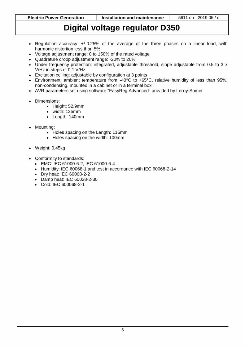
• Dimensions:
• Height: 52.9mm • width: 125mm • Length: 140mm
• Mounting:
• Holes spacing on the Length: 115mm • Holes spacing on the width: 100mm
• Weight: 0.45kg
• Conformity to standards:
• EMC: IEC 61000-6-2, IEC 61000-6-4 • Humidity: IEC 60068-1 and test in accordance with IEC 60068-2-14 • Dry heat: IEC 60068-2-2 • Damp heat: IEC 60028-2-30 • Cold: IEC 600068-2-1
Electric Power Generation Installation and maintenance 5611 en - 2019.05 / d
Digital voltage regulator D350
9
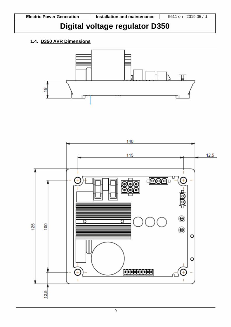
1.4. D350 AVR Dimensions
Electric Power Generation Installation and maintenance 5611 en - 2019.05 / d
Digital voltage regulator D350
10
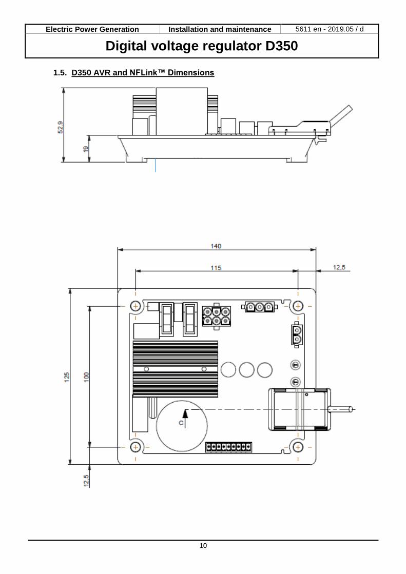
1.5. D350 AVR and NFLink™ Dimensions
Electric Power Generation Installation and maintenance 5611 en - 2019.05 / d
Digital voltage regulator D350
11
1.6. Mounting
The D350 is mounted on a mechanical part on the terminal box or the cabinet with 4xM5 screws and the nominal screwing torque is de 2.5 N.m.
1.7. Wiring
The D350 must be connected to the different measurement, power and control signals to ensure the proper regulation functions.
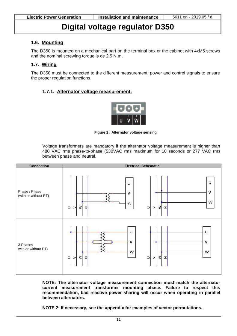
1.7.1. Alternator voltage measurement:
Figure 1 : Alternator voltage sensing
Voltage transformers are mandatory if the alternator voltage measurement is higher than 480 VAC rms phase-to-phase (530VAC rms maximum for 10 seconds or 277 VAC rms between phase and neutral.
Connection Electrical Schematic
Phase / Phase (with or without PT)
3 Phases with or without PT)
NOTE: The alternator voltage measurement connection must match the alternator current measurement transformer mounting phase. Failure to respect this recommendation, bad reactive power sharing will occur when operating in parallel between alternators. NOTE 2: If necessary, see the appendix for examples of vector permutations.
Electric Power Generation Installation and maintenance 5611 en - 2019.05 / d
Digital voltage regulator D350
12
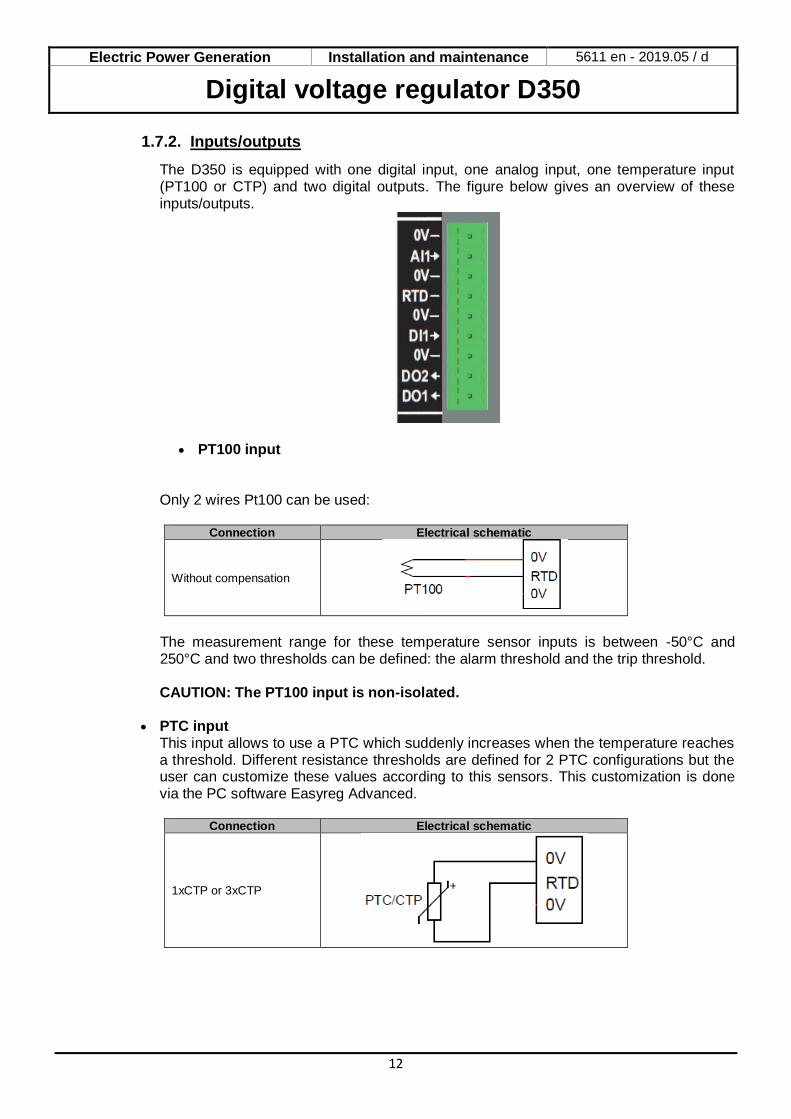
1.7.2. Inputs/outputs
The D350 is equipped with one digital input, one analog input, one temperature input (PT100 or CTP) and two digital outputs. The figure below gives an overview of these inputs/outputs.
• PT100 input
Only 2 wires Pt100 can be used:
Connection Electrical schematic
Without compensation
The measurement range for these temperature sensor inputs is between -50°C and 250°C and two thresholds can be defined: the alarm threshold and the trip threshold.
CAUTION: The PT100 input is non-isolated.
• PTC input This input allows to use a PTC which suddenly increases when the temperature reaches a threshold. Different resistance thresholds are defined for 2 PTC configurations but the user can customize these values according to this sensors. This customization is done via the PC software Easyreg Advanced.
Connection Electrical schematic
1xCTP or 3xCTP
Electric Power Generation Installation and maintenance 5611 en - 2019.05 / d
Digital voltage regulator D350
13
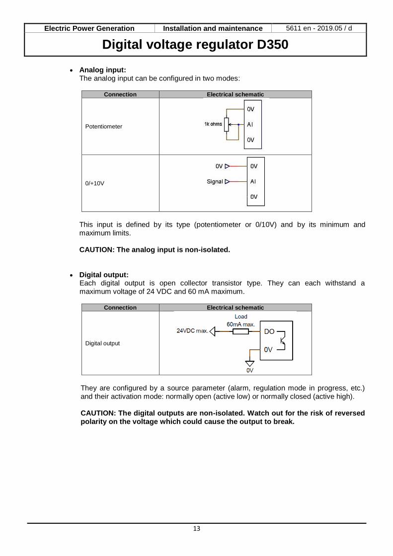
• Analog input: The analog input can be configured in two modes:
Connection Electrical schematic
Potentiometer
0/+10V
This input is defined by its type (potentiometer or 0/10V) and by its minimum and maximum limits. CAUTION: The analog input is non-isolated.
• Digital output:
Each digital output is open collector transistor type. They can each withstand a maximum voltage of 24 VDC and 60 mA maximum.
Connection Electrical schematic
Digital output
They are configured by a source parameter (alarm, regulation mode in progress, etc.) and their activation mode: normally open (active low) or normally closed (active high). CAUTION: The digital outputs are non-isolated. Watch out for the risk of reversed polarity on the voltage which could cause the output to break.
Electric Power Generation Installation and maintenance 5611 en - 2019.05 / d
Digital voltage regulator D350
14
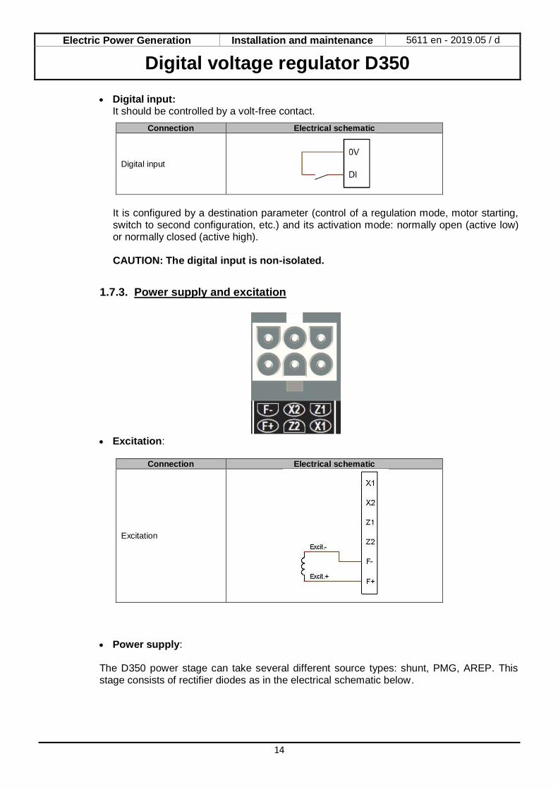
• Digital input: It should be controlled by a volt-free contact.
Connection Electrical schematic
Digital input
It is configured by a destination parameter (control of a regulation mode, motor starting, switch to second configuration, etc.) and its activation mode: normally open (active low) or normally closed (active high).
CAUTION: The digital input is non-isolated.
1.7.3. Power supply and excitation
• Excitation:
Connection Electrical schematic
Excitation
• Power supply: The D350 power stage can take several different source types: shunt, PMG, AREP. This stage consists of rectifier diodes as in the electrical schematic below.
Electric Power Generation Installation and maintenance 5611 en - 2019.05 / d
Digital voltage regulator D350
15
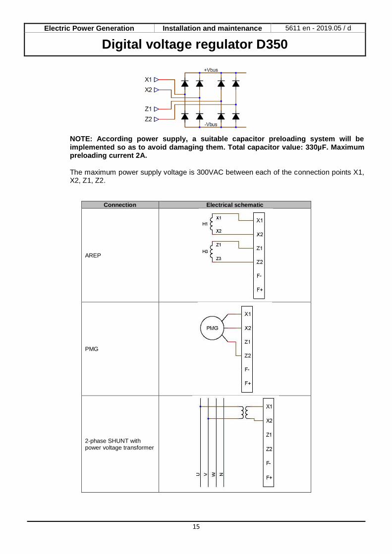
NOTE: According power supply, a suitable capacitor preloading system will be implemented so as to avoid damaging them. Total capacitor value: 330µF. Maximum preloading current 2A. The maximum power supply voltage is 300VAC between each of the connection points X1, X2, Z1, Z2.
Connection Electrical schematic
AREP
PMG
2-phase SHUNT with power voltage transformer
Electric Power Generation Installation and maintenance 5611 en - 2019.05 / d
Digital voltage regulator D350
16
Connection Electrical schematic
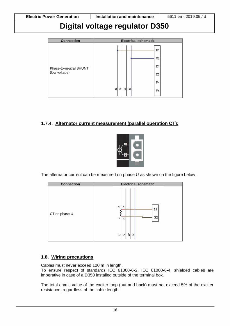
Phase-to-neutral SHUNT (low voltage)
1.7.4. Alternator current measurement (parallel operation CT):
The alternator current can be measured on phase U as shown on the figure below.
Connection Electrical schematic
CT on phase U
1.8. Wiring precautions
Cables must never exceed 100 m in length. To ensure respect of standards IEC 61000-6-2, IEC 61000-6-4, shielded cables are imperative in case of a D350 installed outside of the terminal box. The total ohmic value of the exciter loop (out and back) must not exceed 5% of the exciter resistance, regardless of the cable length.
Electric Power Generation Installation and maintenance 5611 en - 2019.05 / d
Digital voltage regulator D350
17
The total ohmic value of the power system cables must not exceed 5% of the exciter resistance, regardless of the cable length.
For information, the resistance at 20°C in m/m for copper cables is approximately:
Cross-section (mm²) Resistance (m/m)
1,5 13,3
2,5 7,98
4 4,95
6 3,3
10 1,91
Calculation example: For a 10 ohm exciter
• Maximum cable resistance = 0.5 ohms (2 x 0.25 ohms) • Cross-section as a function of the distance between the AVR and the alternator:
Distance (m) Cross-section (mm²)
30 2,5
50 4
75 6
100 10
Electric Power Generation Installation and maintenance 5611 en - 2019.05 / d
Digital voltage regulator D350
18
2. Operations Instructions
The D350 AVR has operations range limits that must be respected. Incorrect settings of voltages and currents could lead to partial or total damage of the regulator and/or the alternator.
2.1. Description of manual controls and signaling
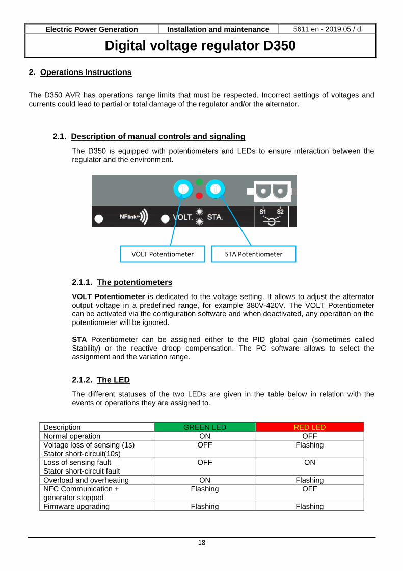
The D350 is equipped with potentiometers and LEDs to ensure interaction between the regulator and the environment.
2.1.1. The potentiometers
VOLT Potentiometer is dedicated to the voltage setting. It allows to adjust the alternator output voltage in a predefined range, for example 380V-420V. The VOLT Potentiometer can be activated via the configuration software and when deactivated, any operation on the potentiometer will be ignored. STA Potentiometer can be assigned either to the PID global gain (sometimes called Stability) or the reactive droop compensation. The PC software allows to select the assignment and the variation range.
2.1.2. The LED
The different statuses of the two LEDs are given in the table below in relation with the events or operations they are assigned to.
Description GREEN LED RED LED
Normal operation ON OFF
Voltage loss of sensing (1s) Stator short-circuit(10s)
OFF Flashing
Loss of sensing fault Stator short-circuit fault
OFF ON
Overload and overheating ON Flashing
NFC Communication + generator stopped
Flashing OFF
Firmware upgrading Flashing Flashing
STA Potentiometer VOLT Potentiometer
Electric Power Generation Installation and maintenance 5611 en - 2019.05 / d
Digital voltage regulator D350
19
2.2. Description of the operating modes
The various regulation modes to be configured depend on the alternator operation (standalone, parallel between machines). Based on these different operating modes, certain function will need to be enabled.3 The simplest examples are shown below.
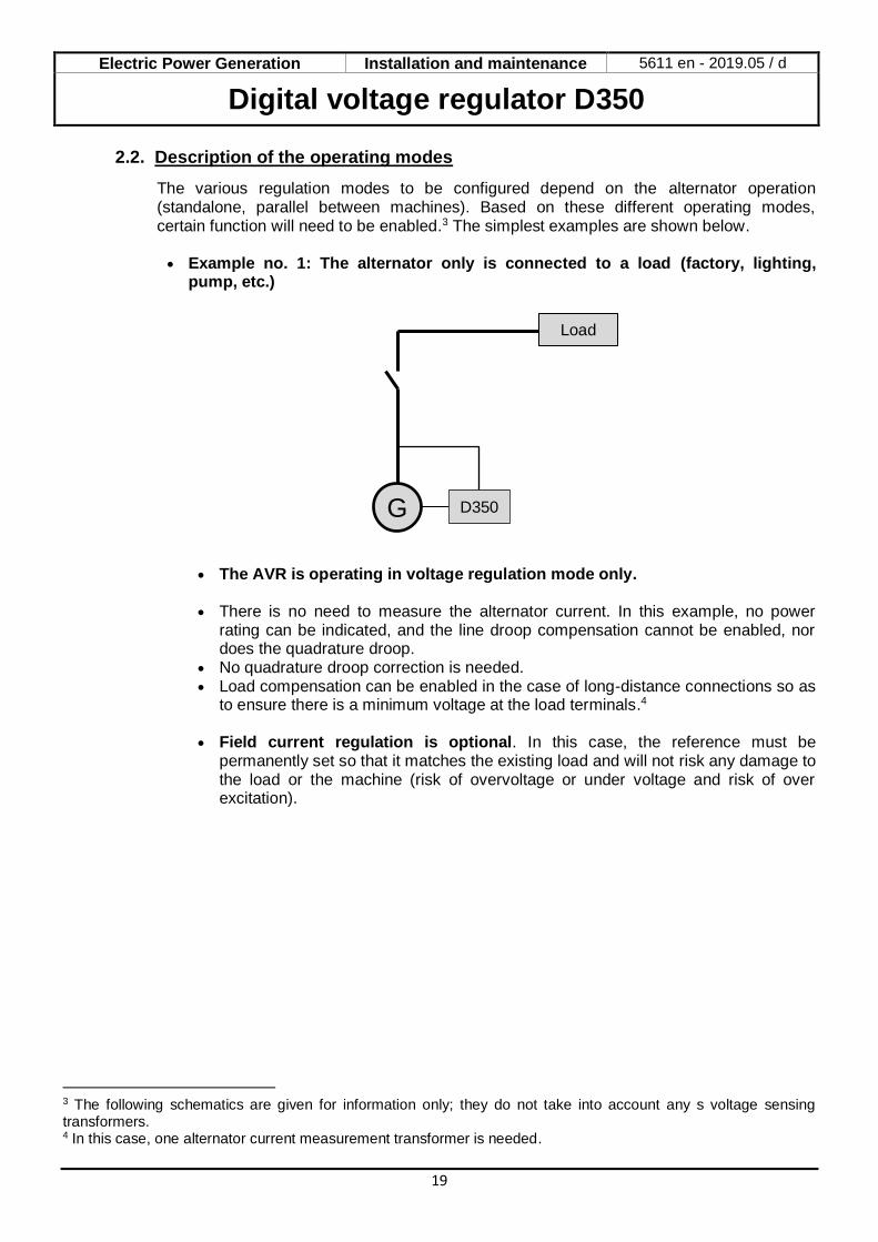
• Example no. 1: The alternator only is connected to a load (factory, lighting,
pump, etc.)
• The AVR is operating in voltage regulation mode only. • There is no need to measure the alternator current. In this example, no power
rating can be indicated, and the line droop compensation cannot be enabled, nor does the quadrature droop.
• No quadrature droop correction is needed. • Load compensation can be enabled in the case of long-distance connections so as
to ensure there is a minimum voltage at the load terminals.4
• Field current regulation is optional. In this case, the reference must be permanently set so that it matches the existing load and will not risk any damage to the load or the machine (risk of overvoltage or under voltage and risk of over excitation).
3 The following schematics are given for information only; they do not take into account any s voltage sensing transformers. 4 In this case, one alternator current measurement transformer is needed.
G
Load
D350
Electric Power Generation Installation and maintenance 5611 en - 2019.05 / d
Digital voltage regulator D350
20
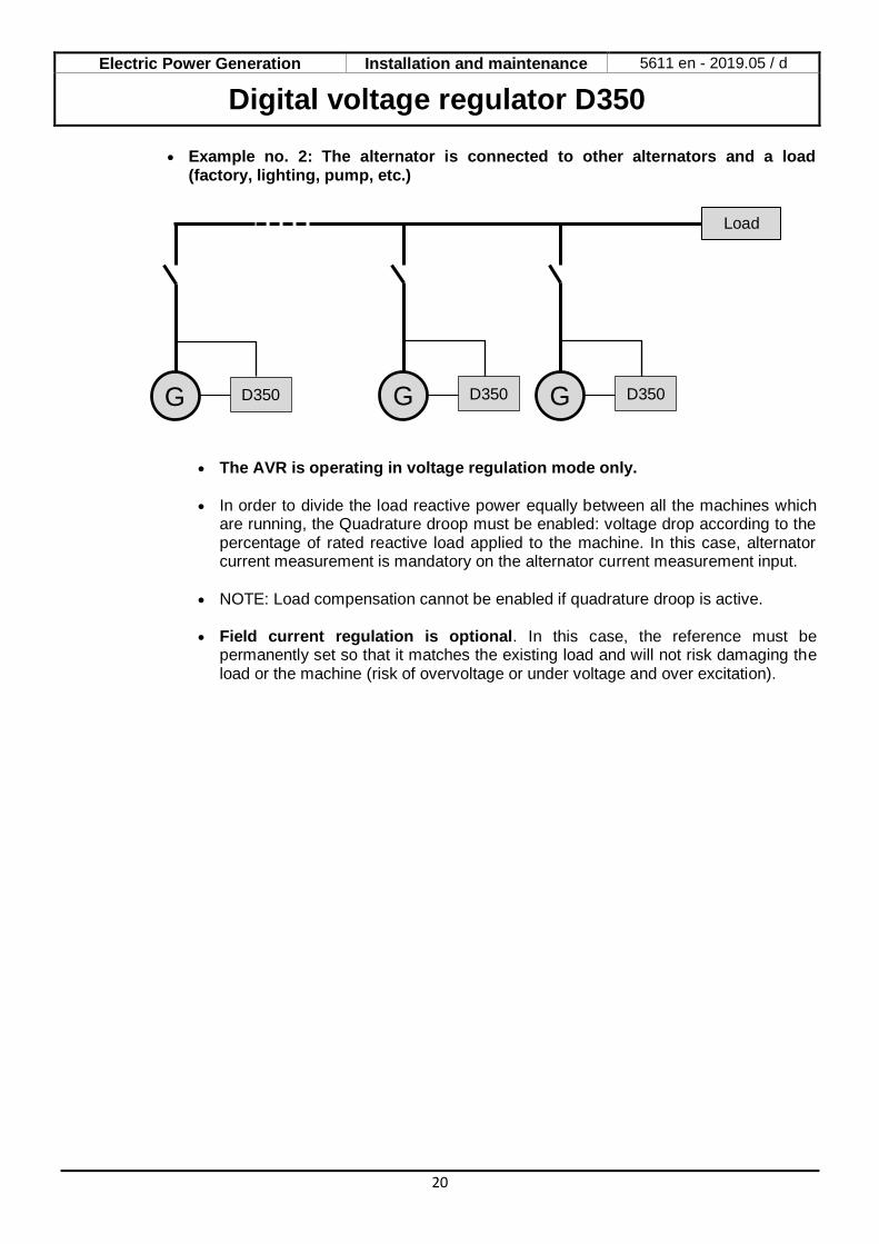
• Example no. 2: The alternator is connected to other alternators and a load (factory, lighting, pump, etc.)
• The AVR is operating in voltage regulation mode only.
• In order to divide the load reactive power equally between all the machines which
are running, the Quadrature droop must be enabled: voltage drop according to the percentage of rated reactive load applied to the machine. In this case, alternator current measurement is mandatory on the alternator current measurement input.
• NOTE: Load compensation cannot be enabled if quadrature droop is active. • Field current regulation is optional. In this case, the reference must be
permanently set so that it matches the existing load and will not risk damaging the load or the machine (risk of overvoltage or under voltage and over excitation).
G D350
Load
G D350 G D350

Electric Power Generation Installation and maintenance 5611 en - 2019.05 / d
Digital voltage regulator D350
21
3. Setting instructions
3.1. PC Software
All the D350 settings can be entered using the "EasyReg Advanced" software supplied with the AVR. The parameter-setting pages describe primarily the alternator parameters, regulations, limits, and protection devices.
3.1.1. Software installation
EasyReg Advanced® is the software to be used for configurating the regulator. NOTE: This program is only compatible with computers running WINDOWS® versions Windows 7 and Windows 10 operating systems. Execute this program, checking first that you have “Administrator” rights for your terminal. Step 1: Choose the installation language
Step 2: Choose the installation type: • Quick installation: the files are copied automatically and the software directory is
created • Custom installation:
• Choose the installation directory
• After selecting the directory, click “Next”
Electric Power Generation Installation and maintenance 5611 en - 2019.05 / d
Digital voltage regulator D350
22
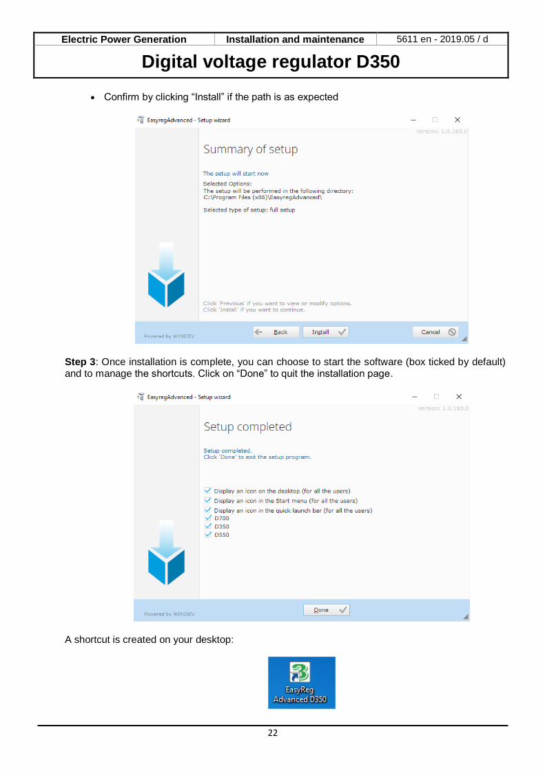
• Confirm by clicking “Install” if the path is as expected
Step 3: Once installation is complete, you can choose to start the software (box ticked by default) and to manage the shortcuts. Click on “Done” to quit the installation page.
A shortcut is created on your desktop:
Electric Power Generation Installation and maintenance 5611 en - 2019.05 / d
Digital voltage regulator D350
23
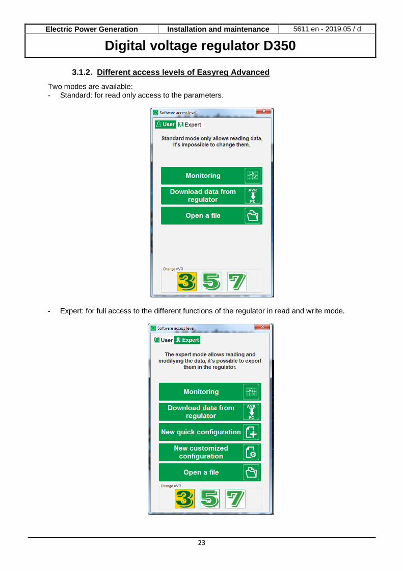
3.1.2. Different access levels of Easyreg Advanced
Two modes are available: - Standard: for read only access to the parameters.
- Expert: for full access to the different functions of the regulator in read and write mode.
Electric Power Generation Installation and maintenance 5611 en - 2019.05 / d
Digital voltage regulator D350
24
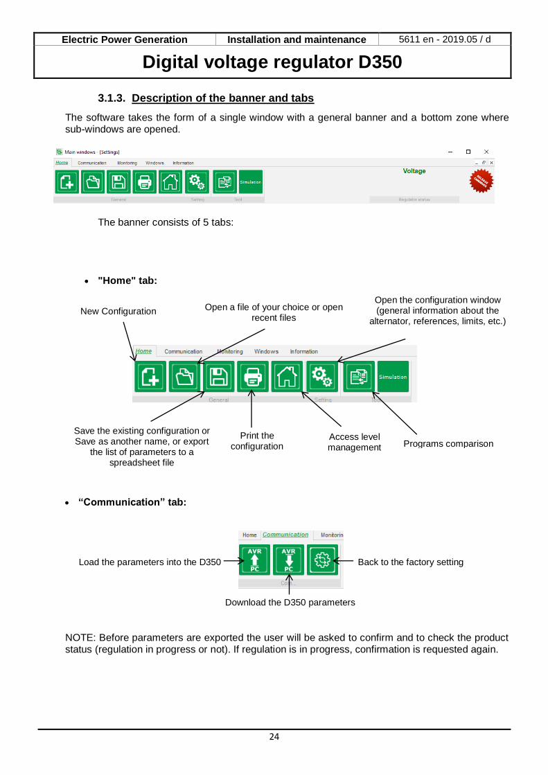
3.1.3. Description of the banner and tabs
The software takes the form of a single window with a general banner and a bottom zone where sub-windows are opened.
The banner consists of 5 tabs:
• "Home" tab:
• “Communication” tab:
NOTE: Before parameters are exported the user will be asked to confirm and to check the product status (regulation in progress or not). If regulation is in progress, confirmation is requested again.
Load the parameters into the D350
Download the D350 parameters
Back to the factory setting
Save the existing configuration or Save as another name, or export
the list of parameters to a spreadsheet file
Programs comparison Access level management
Print the configuration
New Configuration Open a file of your choice or open recent files
Open the configuration window (general information about the
alternator, references, limits, etc.)
Electric Power Generation Installation and maintenance 5611 en - 2019.05 / d
Digital voltage regulator D350
25
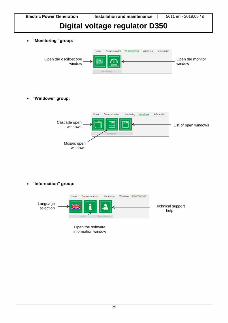
• “Monitoring” group:
• “Windows” group:
• "Information" group:
Open the oscilloscope window
Open the monitor window
Cascade open windows
Mosaic open windows
List of open windows
Language selection
Open the software information window
Technical support help
Electric Power Generation Installation and maintenance 5611 en - 2019.05 / d
Digital voltage regulator D350
26
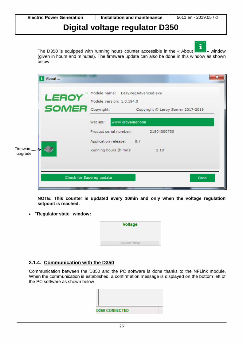
The D350 is equipped with running hours counter accessible in the « About » window (given in hours and minutes). The firmware update can also be done in this window as shown below.
NOTE: This counter is updated every 10min and only when the voltage regulation setpoint is reached.
• "Regulator state" window:
3.1.4. Communication with the D350
Communication between the D350 and the PC software is done thanks to the NFLink module. When the communication is established, a confirmation message is displayed on the bottom left of the PC software as shown below.
Firmware upgrade
Electric Power Generation Installation and maintenance 5611 en - 2019.05 / d
Digital voltage regulator D350
27
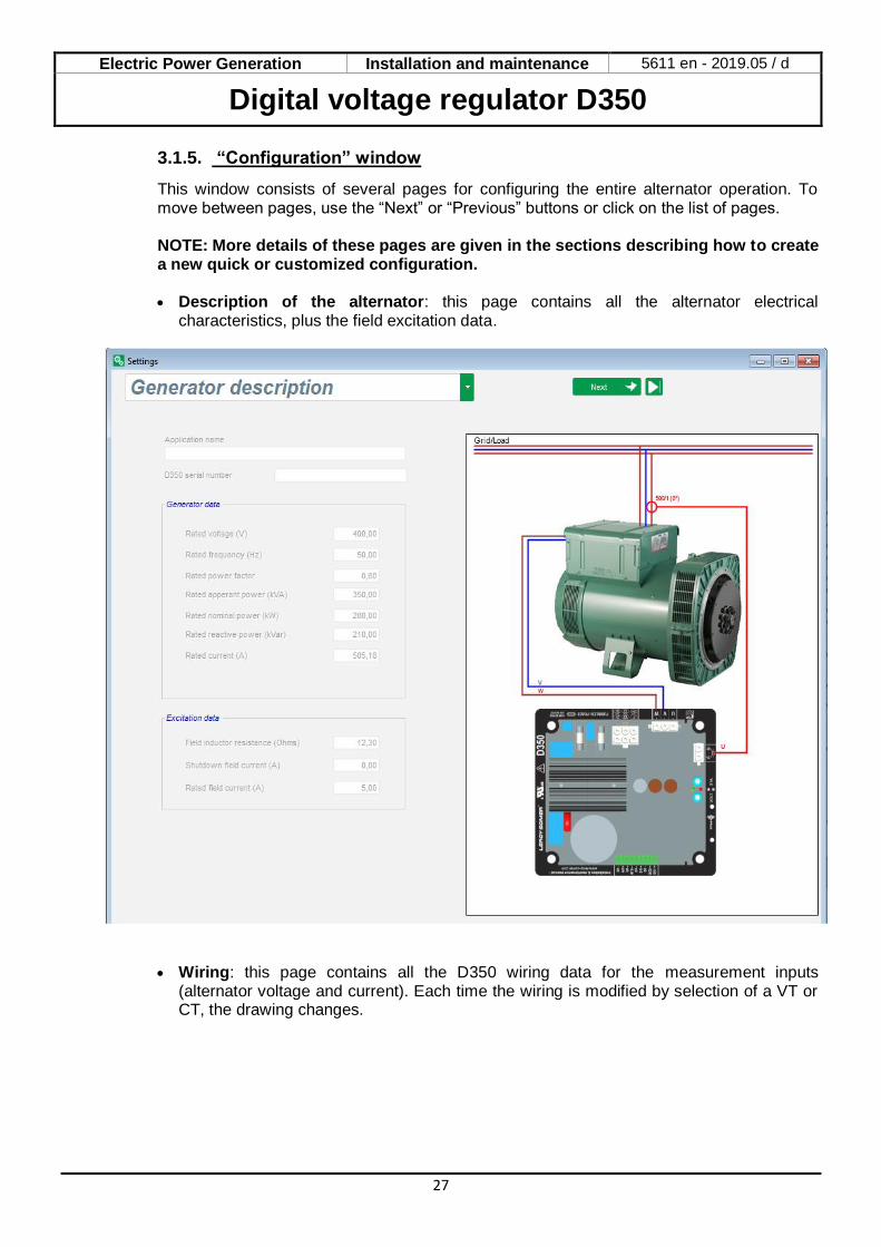
3.1.5. “Configuration” window
This window consists of several pages for configuring the entire alternator operation. To move between pages, use the “Next” or “Previous” buttons or click on the list of pages.
NOTE: More details of these pages are given in the sections describing how to create a new quick or customized configuration.
• Description of the alternator: this page contains all the alternator electrical
characteristics, plus the field excitation data.
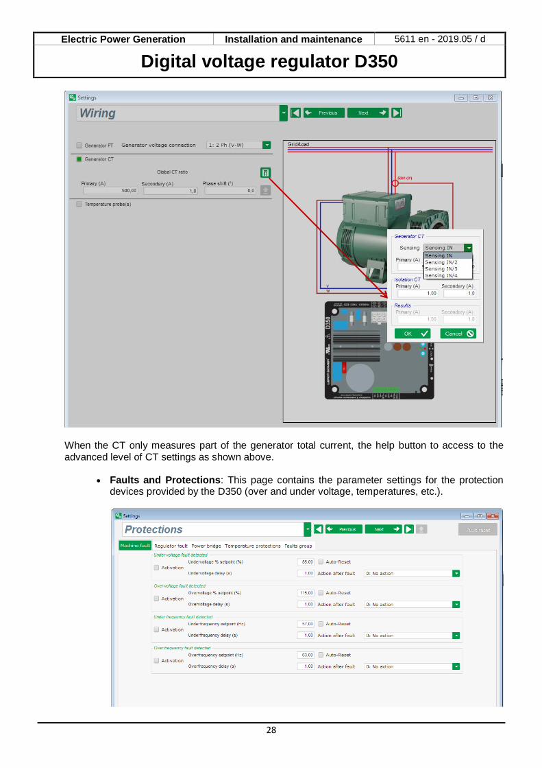
• Wiring: this page contains all the D350 wiring data for the measurement inputs
(alternator voltage and current). Each time the wiring is modified by selection of a VT or CT, the drawing changes.
Electric Power Generation Installation and maintenance 5611 en - 2019.05 / d
Digital voltage regulator D350
28
When the CT only measures part of the generator total current, the help button to access to the advanced level of CT settings as shown above.
• Faults and Protections: This page contains the parameter settings for the protection
devices provided by the D350 (over and under voltage, temperatures, etc.).

Electric Power Generation Installation and maintenance 5611 en - 2019.05 / d
Digital voltage regulator D350
29
• Regulation modes: this page contains all the regulation parameter settings: active regulations, references and their adjustments.
• PID settings: this page contains all the values for the PID settings.
Electric Power Generation Installation and maintenance 5611 en - 2019.05 / d
Digital voltage regulator D350
30
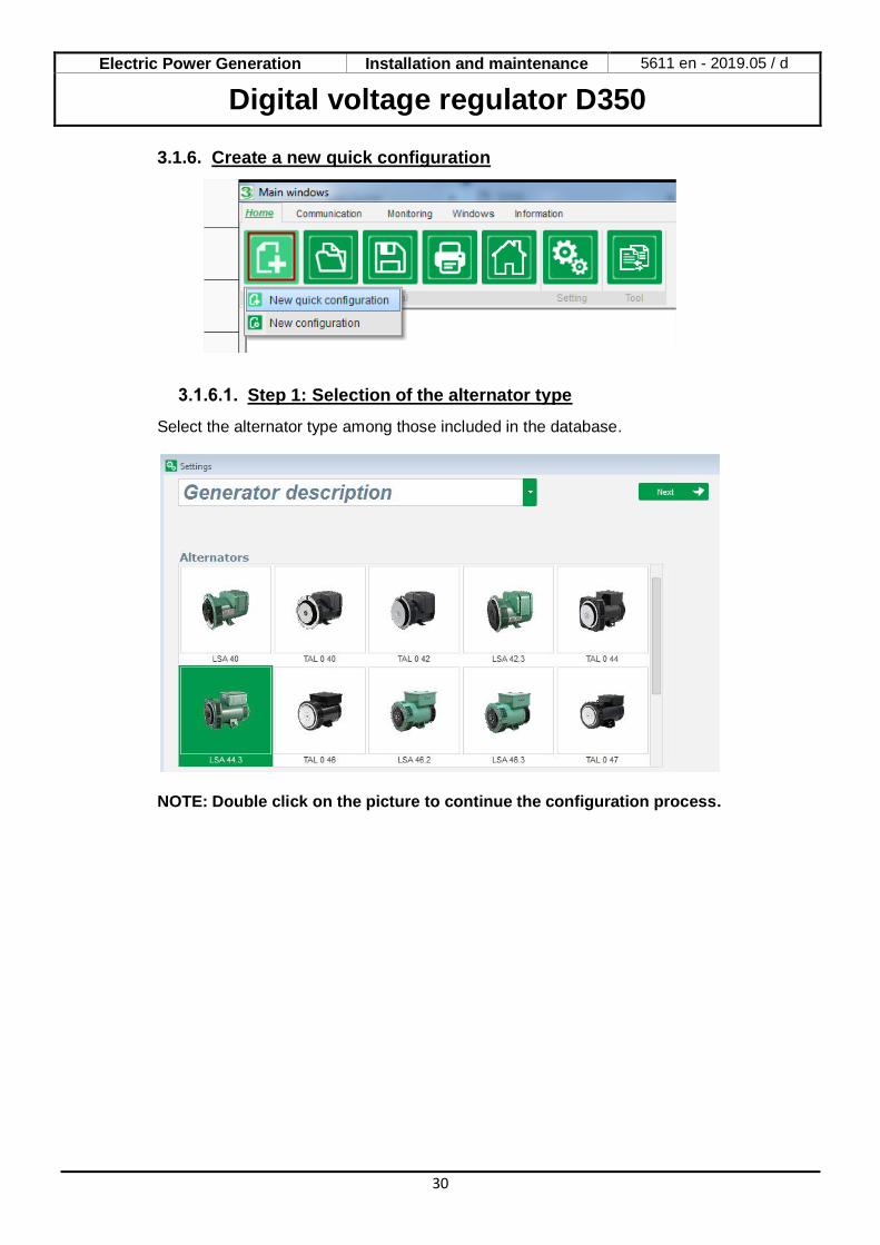
3.1.6. Create a new quick configuration
Step 1: Selection of the alternator type
Select the alternator type among those included in the database.
NOTE: Double click on the picture to continue the configuration process.
Electric Power Generation Installation and maintenance 5611 en - 2019.05 / d
Digital voltage regulator D350
31
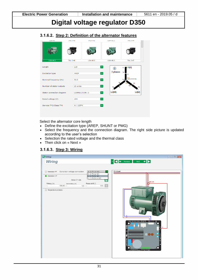
Step 2: Definition of the alternator features
Select the alternator core length • Define the excitation type (AREP, SHUNT or PMG) • Select the frequency and the connection diagram. The right side picture is updated
according to the user’s selection • Selection the rated voltage and the thermal class • Then click on « Next »
Step 3: Wiring
Electric Power Generation Installation and maintenance 5611 en - 2019.05 / d
Digital voltage regulator D350
32
When a PT is used: Tick the « Alternator PT » box and fill the primary and the secondary of the voltage transformer. When a CT is used: Tick the « Alternator CT » box and fill the primary and the secondary of the current transformer.
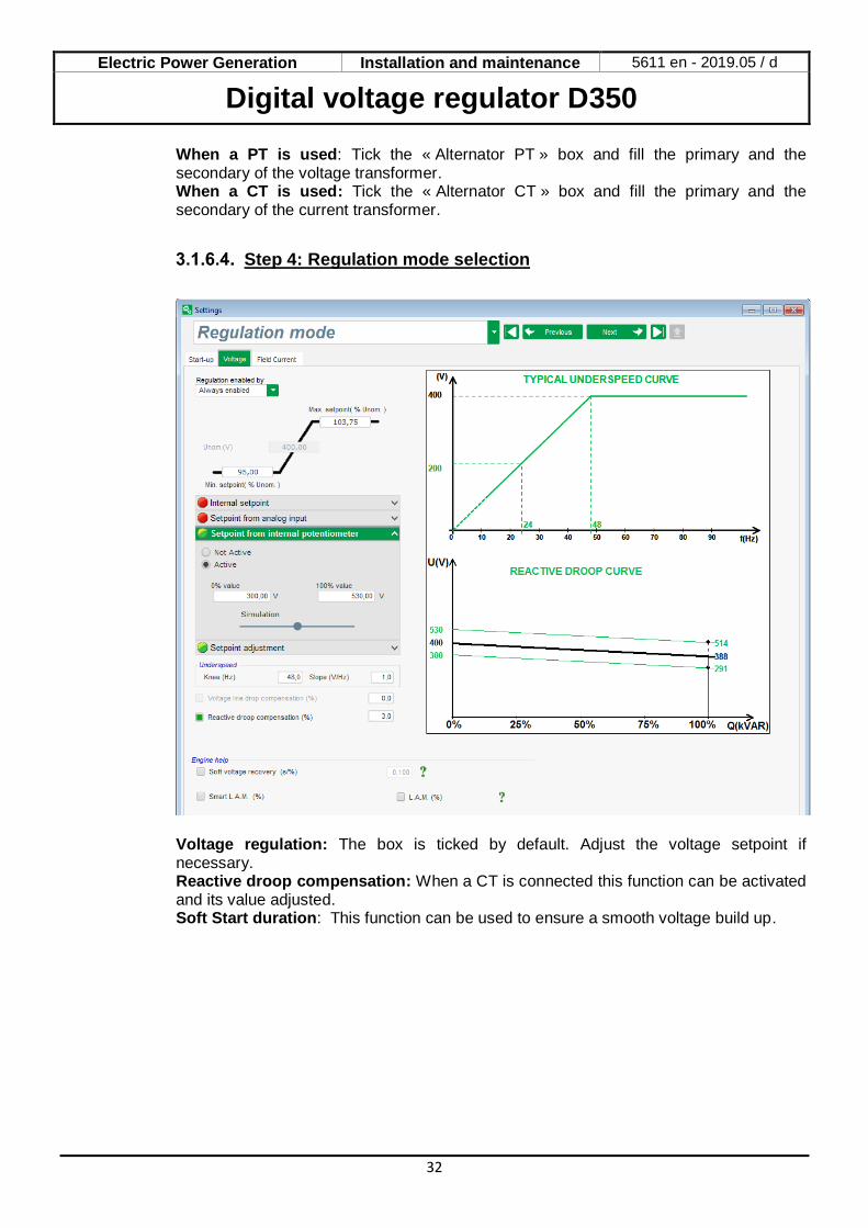
Step 4: Regulation mode selection
Voltage regulation: The box is ticked by default. Adjust the voltage setpoint if necessary. Reactive droop compensation: When a CT is connected this function can be activated and its value adjusted. Soft Start duration: This function can be used to ensure a smooth voltage build up.
Electric Power Generation Installation and maintenance 5611 en - 2019.05 / d
Digital voltage regulator D350
33
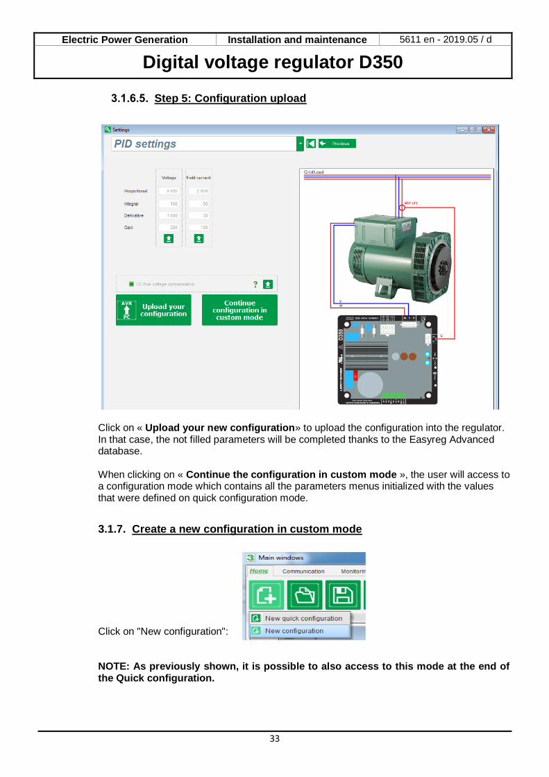
Step 5: Configuration upload
Click on « Upload your new configuration» to upload the configuration into the regulator. In that case, the not filled parameters will be completed thanks to the Easyreg Advanced database. When clicking on « Continue the configuration in custom mode », the user will access to a configuration mode which contains all the parameters menus initialized with the values that were defined on quick configuration mode.
3.1.7. Create a new configuration in custom mode
Click on "New configuration": NOTE: As previously shown, it is possible to also access to this mode at the end of the Quick configuration.

Electric Power Generation Installation and maintenance 5611 en - 2019.05 / d
Digital voltage regulator D350
34
The sequence of configuration steps is shown in the diagram below:
Step 1Description of the alternator
Step 2AVR wiring
Step 3Definition of overexcitation limits
Step 8 Inputs/outputs Settings
Step 9Log Events
Step 10Second configuraiton definition
Step 7PID gains settings
Is there a CT on the alternator ?
Step 4Definition of the stator current
monitoring
Yes
Step 5Definition of the protections
No
Step 6Regulation mode
Step 1: Description of the alternator
• Describe all the alternator characteristics: voltage (in Volts), apparent power (in kVA), frequency (in Hz), and power factor.
• Fields: rated current, reactive power and active power are calculated automatically.
Electric Power Generation Installation and maintenance 5611 en - 2019.05 / d
Digital voltage regulator D350
35
• Describe all the field excitation characteristics: exciter field resistance (in ohms), shutdown field current (in Amps), and rated field current (in Amps).
• Click on the “Next” button
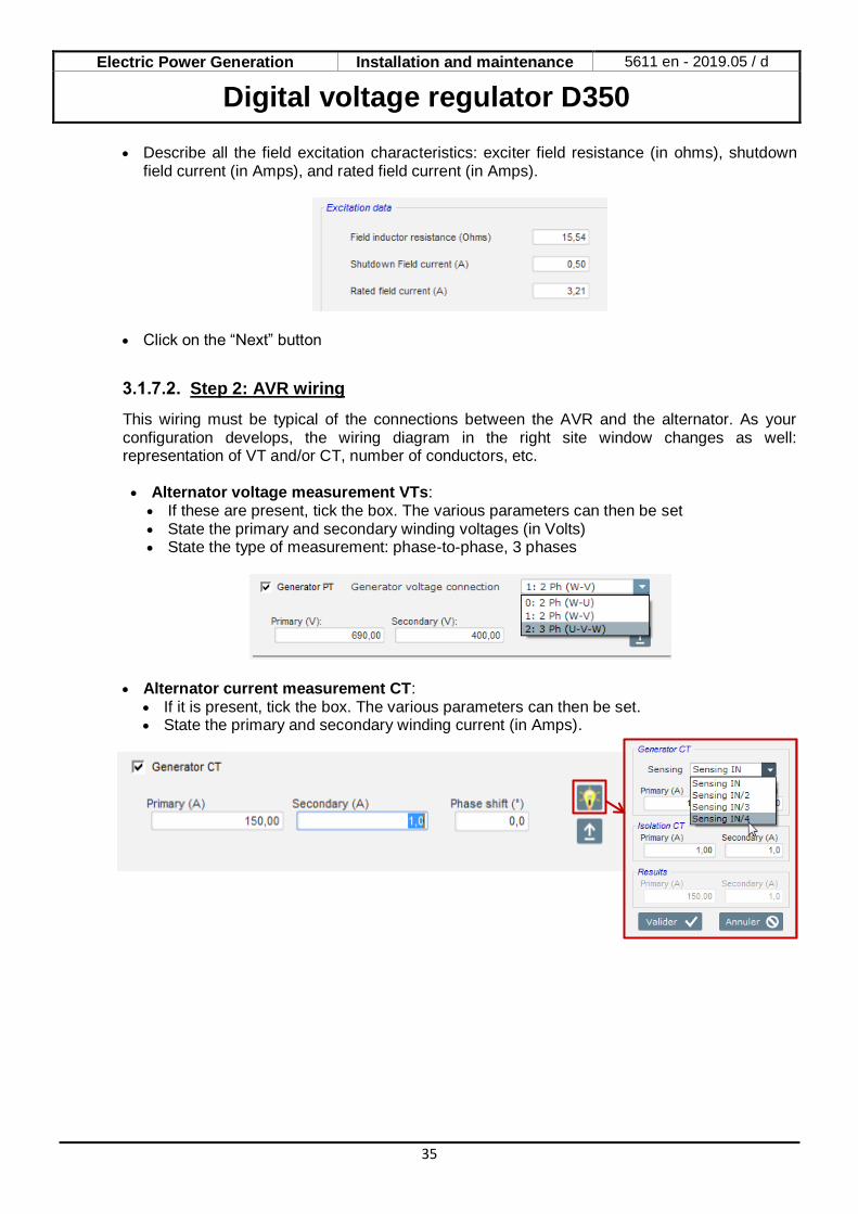
Step 2: AVR wiring
This wiring must be typical of the connections between the AVR and the alternator. As your configuration develops, the wiring diagram in the right site window changes as well: representation of VT and/or CT, number of conductors, etc. • Alternator voltage measurement VTs: • If these are present, tick the box. The various parameters can then be set • State the primary and secondary winding voltages (in Volts) • State the type of measurement: phase-to-phase, 3 phases
• Alternator current measurement CT: • If it is present, tick the box. The various parameters can then be set. • State the primary and secondary winding current (in Amps).
Electric Power Generation Installation and maintenance 5611 en - 2019.05 / d
Digital voltage regulator D350
36
NOTE: • The phase shift value should be set during tests and commissioning. It is used to
compensate for the phase difference caused by the CT and VTs. • When the CT only measures part of the generator total current, the advanced CT
configuration mode must be used to complet the configuration.
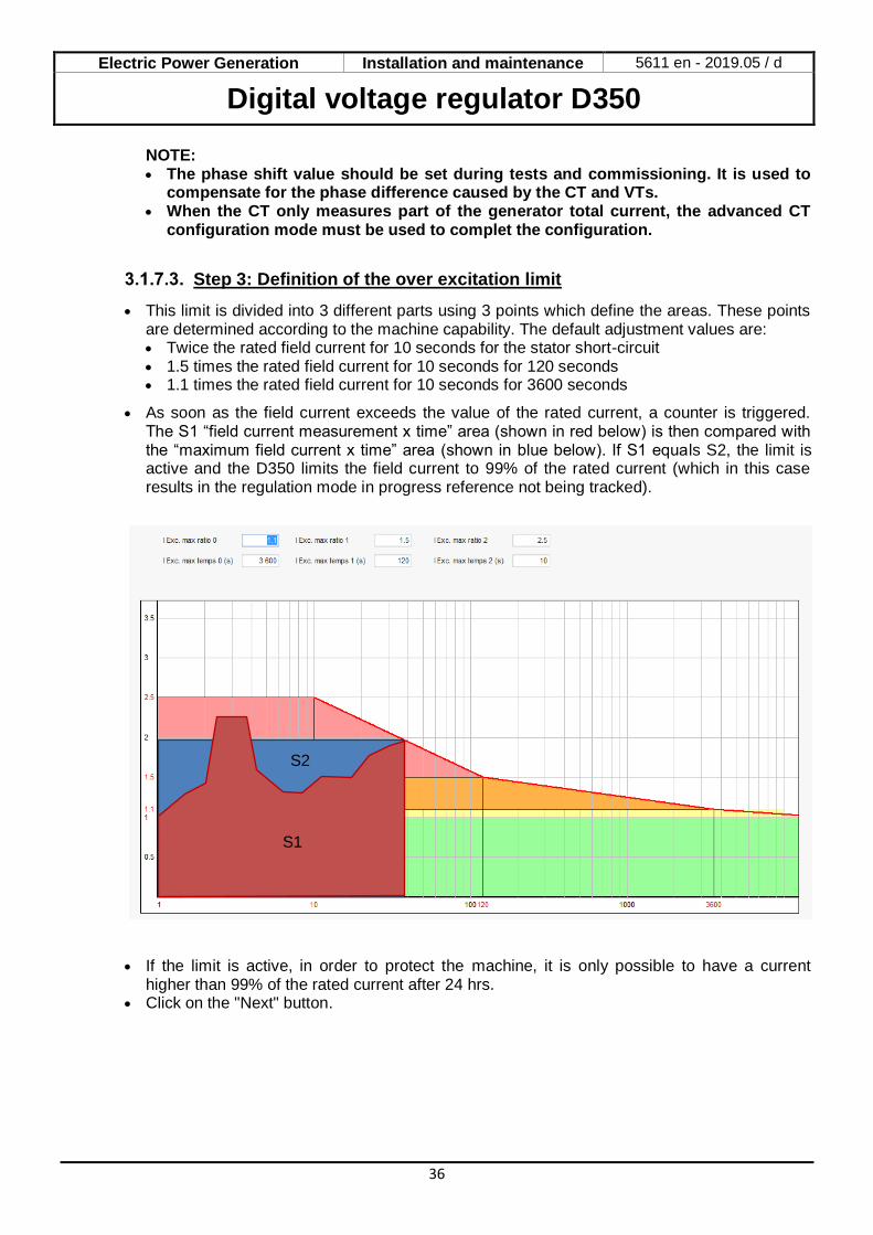
Step 3: Definition of the over excitation limit
• This limit is divided into 3 different parts using 3 points which define the areas. These points are determined according to the machine capability. The default adjustment values are: • Twice the rated field current for 10 seconds for the stator short-circuit • 1.5 times the rated field current for 10 seconds for 120 seconds • 1.1 times the rated field current for 10 seconds for 3600 seconds
• As soon as the field current exceeds the value of the rated current, a counter is triggered. The S1 “field current measurement x time” area (shown in red below) is then compared with the “maximum field current x time” area (shown in blue below). If S1 equals S2, the limit is active and the D350 limits the field current to 99% of the rated current (which in this case results in the regulation mode in progress reference not being tracked).
• If the limit is active, in order to protect the machine, it is only possible to have a current
higher than 99% of the rated current after 24 hrs. • Click on the "Next" button.
S2
S1
Electric Power Generation Installation and maintenance 5611 en - 2019.05 / d
Digital voltage regulator D350
37
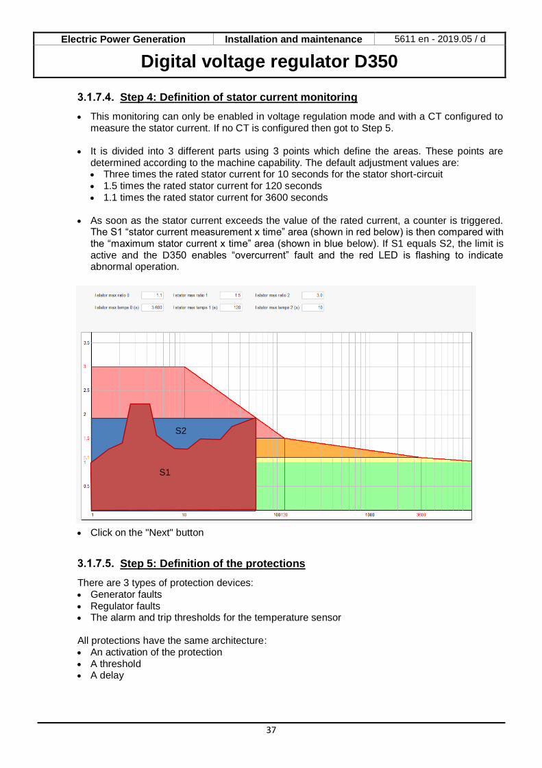
Step 4: Definition of stator current monitoring
• This monitoring can only be enabled in voltage regulation mode and with a CT configured to measure the stator current. If no CT is configured then got to Step 5.
• It is divided into 3 different parts using 3 points which define the areas. These points are
determined according to the machine capability. The default adjustment values are: • Three times the rated stator current for 10 seconds for the stator short-circuit • 1.5 times the rated stator current for 120 seconds • 1.1 times the rated stator current for 3600 seconds
• As soon as the stator current exceeds the value of the rated current, a counter is triggered.
The S1 “stator current measurement x time” area (shown in red below) is then compared with the “maximum stator current x time” area (shown in blue below). If S1 equals S2, the limit is active and the D350 enables “overcurrent” fault and the red LED is flashing to indicate abnormal operation.
• Click on the "Next" button
Step 5: Definition of the protections
There are 3 types of protection devices: • Generator faults • Regulator faults • The alarm and trip thresholds for the temperature sensor All protections have the same architecture: • An activation of the protection • A threshold • A delay
S2
S1
Electric Power Generation Installation and maintenance 5611 en - 2019.05 / d
Digital voltage regulator D350
38
• An action to realize (or not) when the delay is over. This action is chosen in a list: • No action: the regulation will continue • Regulation stopped: the excitation is then stopped • Regulation in field current mode at shutdown value • Regulation in field current mode at the field current value before fault: no bump in the
regulation
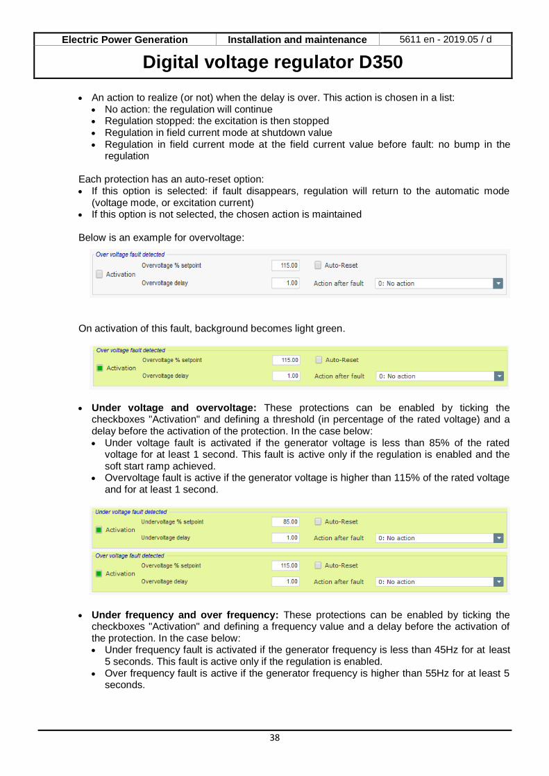
Each protection has an auto-reset option: • If this option is selected: if fault disappears, regulation will return to the automatic mode
(voltage mode, or excitation current) • If this option is not selected, the chosen action is maintained Below is an example for overvoltage:
On activation of this fault, background becomes light green.
• Under voltage and overvoltage: These protections can be enabled by ticking the
checkboxes "Activation" and defining a threshold (in percentage of the rated voltage) and a delay before the activation of the protection. In the case below: • Under voltage fault is activated if the generator voltage is less than 85% of the rated
voltage for at least 1 second. This fault is active only if the regulation is enabled and the soft start ramp achieved.
• Overvoltage fault is active if the generator voltage is higher than 115% of the rated voltage and for at least 1 second.
• Under frequency and over frequency: These protections can be enabled by ticking the checkboxes "Activation" and defining a frequency value and a delay before the activation of the protection. In the case below: • Under frequency fault is activated if the generator frequency is less than 45Hz for at least
5 seconds. This fault is active only if the regulation is enabled. • Over frequency fault is active if the generator frequency is higher than 55Hz for at least 5
seconds.

Electric Power Generation Installation and maintenance 5611 en - 2019.05 / d
Digital voltage regulator D350
39
• Start motor fault: This protection can be enabled by ticking the checkbox "Activation" and defining a delay. In the case below, fault is activated if the generator voltage is less than the voltage setpoint when the 30 second delay is complete.
• Loss of sensing: this protection can be enabled by ticking the checkbox "Activation" and defining a voltage threshold in percentage of the generator voltage setpoint, as well as a delay before activation of the protection device. In the case below, the trip is active if the generator voltage is less than 20% of the voltage setpoint after 1 second.
• Unbalance voltage: this protection can be enabled by ticking the checkbox "Activation" and
defining a percentage of voltage unbalance as well as a delay before activation of the protection device. Calculation of the voltage unbalance is according to the NEMA standard:
𝑈𝑛𝑏𝑎𝑙𝑎𝑛𝑐𝑒 𝑝𝑒𝑟𝑐𝑒𝑛𝑡𝑎𝑔𝑒 =𝑀𝑎𝑥𝑖𝑚𝑢𝑚 𝑔𝑒𝑛𝑒𝑟𝑎𝑡𝑜𝑟 𝑣𝑜𝑙𝑡𝑎𝑔𝑒
𝐴𝑣𝑒𝑟𝑎𝑔𝑒 𝑜𝑓 𝑔𝑒𝑛𝑒𝑟𝑎𝑡𝑜𝑟 𝑣𝑜𝑙𝑡𝑎𝑔𝑒 × 100
In the case below, this fault is activated if the percentage of unbalance is at least 20% after 1 second.
• Short-circuit: this protection can be enabled by ticking the checkbox "Activation" and
defining a minimum stator current threshold in percentage of the generator rated current, as well as a delay before activation of the protection device. In the case below, the trip is active if the generator current measurement is higher than 200% of the rated stator current after 10 seconds.
Electric Power Generation Installation and maintenance 5611 en - 2019.05 / d
Digital voltage regulator D350
40
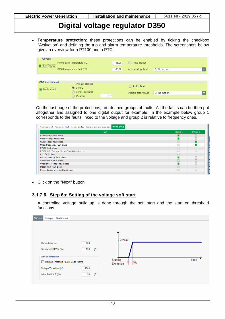
• Temperature protection: these protections can be enabled by ticking the checkbox "Activation" and defining the trip and alarm temperature thresholds. The screenshots below give an overview for a PT100 and a PTC.
On the last page of the protections, are defined groups of faults. All the faults can be then put altogether and assigned to one digital output for example. In the example below group 1 corresponds to the faults linked to the voltage and group 2 is relative to frequency ones.
• Click on the "Next" button
Step 6a: Setting of the voltage soft start
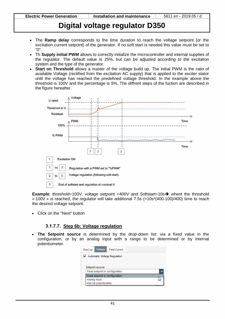
A controlled voltage build up is done through the soft start and the start on threshold functions.
Electric Power Generation Installation and maintenance 5611 en - 2019.05 / d
Digital voltage regulator D350
41
• The Ramp delay corresponds to the time duration to reach the voltage setpoint (or the excitation current setpoint) of the generator. If no soft start is needed this value must be set to "0".
• Th Supply initial PWM allows to correctly initialize the microcontroller and internal supplies of the regulator. The default value is 25%, but can be adjusted according to the excitation system and the type of the generator.
• Start on Threshold allows a master of the voltage build up. The initial PWM is the ratio of available Voltage (rectified from the excitation AC supply) that is applied to the exciter stator until the voltage has reached the predefined voltage threshold. In the example above the threshold is 100V and the percentage is 5%. The diffrent steps of the fuction are described in the figure hereafter.
Example: threshold=100V; voltage setpoint =400V and Softstart=10s➔ whent the threshold « 100V » is reached, the regulator will take additional 7.5s (=10s*(400-100)/400) time to reach the desired voltage setpoint.
• Click on the "Next" button
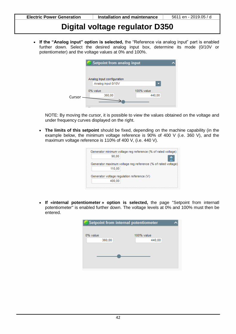
Step 6b: Voltage regulation
• The Setpoint source is determined by the drop-down list: via a fixed value in the configuration, or by an analog input with a range to be determined or by internal potentiometer.
Electric Power Generation Installation and maintenance 5611 en - 2019.05 / d
Digital voltage regulator D350
42
• If the “Analog input” option is selected, the “Reference via analog input” part is enabled further down. Select the desired analog input box, determine its mode (0/10V or potentiometer) and the voltage values at 0% and 100%.
NOTE: By moving the cursor, it is possible to view the values obtained on the voltage and under frequency curves displayed on the right.
• The limits of this setpoint should be fixed, depending on the machine capability (in the
example below, the minimum voltage reference is 90% of 400 V (i.e. 360 V), and the maximum voltage reference is 110% of 400 V, (i.e. 440 V).
• If «internal potentiometer » option is selected, the page "Setpoint from internatl potentiometer" is enabled further down. The voltage levels at 0% and 100% must then be entered.
Cursor
Electric Power Generation Installation and maintenance 5611 en - 2019.05 / d
Digital voltage regulator D350
43
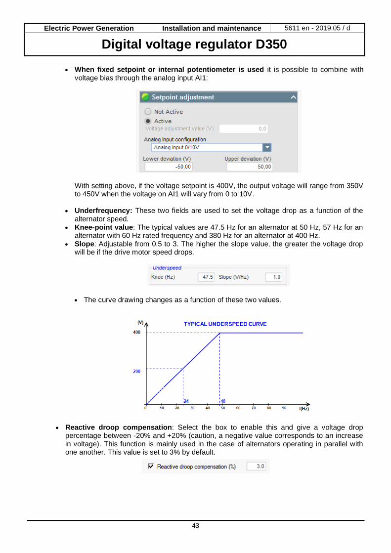
• When fixed setpoint or internal potentiometer is used it is possible to combine with voltage bias through the analog input AI1:
With setting above, if the voltage setpoint is 400V, the output voltage will range from 350V to 450V when the voltage on AI1 will vary from 0 to 10V.
• Underfrequency: These two fields are used to set the voltage drop as a function of the
alternator speed. • Knee-point value: The typical values are 47.5 Hz for an alternator at 50 Hz, 57 Hz for an
alternator with 60 Hz rated frequency and 380 Hz for an alternator at 400 Hz. • Slope: Adjustable from 0.5 to 3. The higher the slope value, the greater the voltage drop
will be if the drive motor speed drops.
• The curve drawing changes as a function of these two values.
• Reactive droop compensation: Select the box to enable this and give a voltage drop percentage between -20% and +20% (caution, a negative value corresponds to an increase in voltage). This function is mainly used in the case of alternators operating in parallel with one another. This value is set to 3% by default.
Electric Power Generation Installation and maintenance 5611 en - 2019.05 / d
Digital voltage regulator D350
44
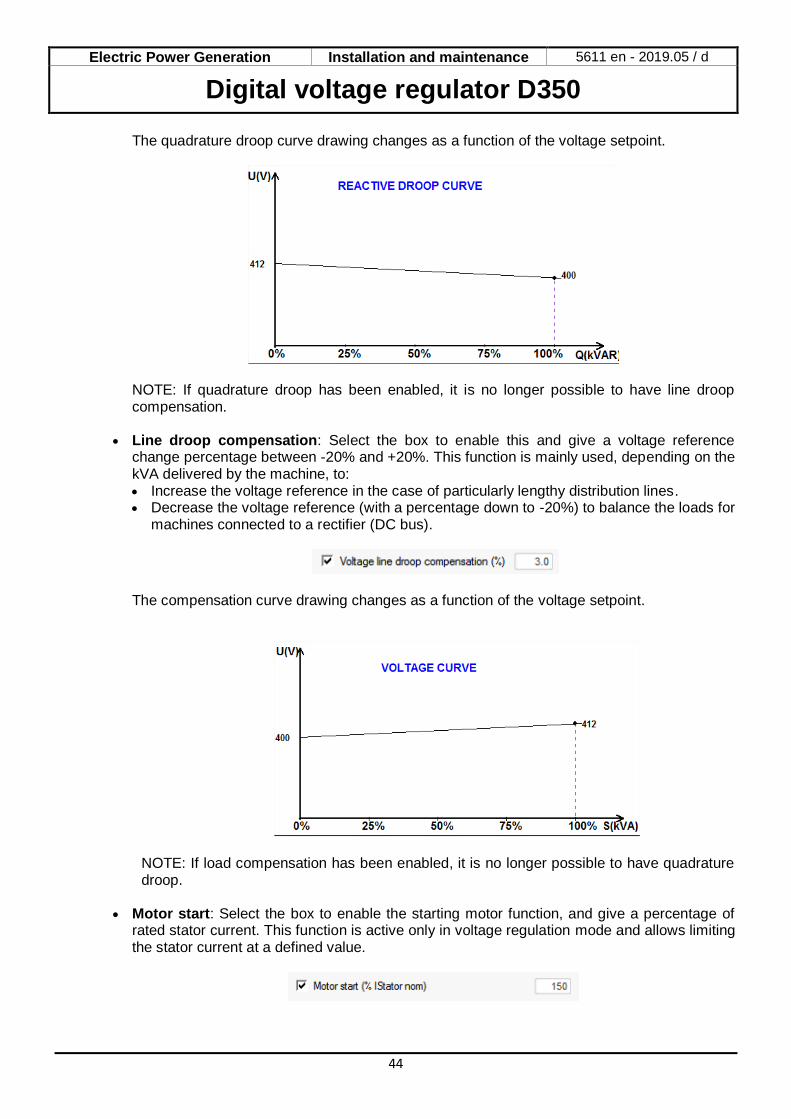
The quadrature droop curve drawing changes as a function of the voltage setpoint.
NOTE: If quadrature droop has been enabled, it is no longer possible to have line droop compensation.
• Line droop compensation: Select the box to enable this and give a voltage reference change percentage between -20% and +20%. This function is mainly used, depending on the kVA delivered by the machine, to: • Increase the voltage reference in the case of particularly lengthy distribution lines. • Decrease the voltage reference (with a percentage down to -20%) to balance the loads for
machines connected to a rectifier (DC bus).
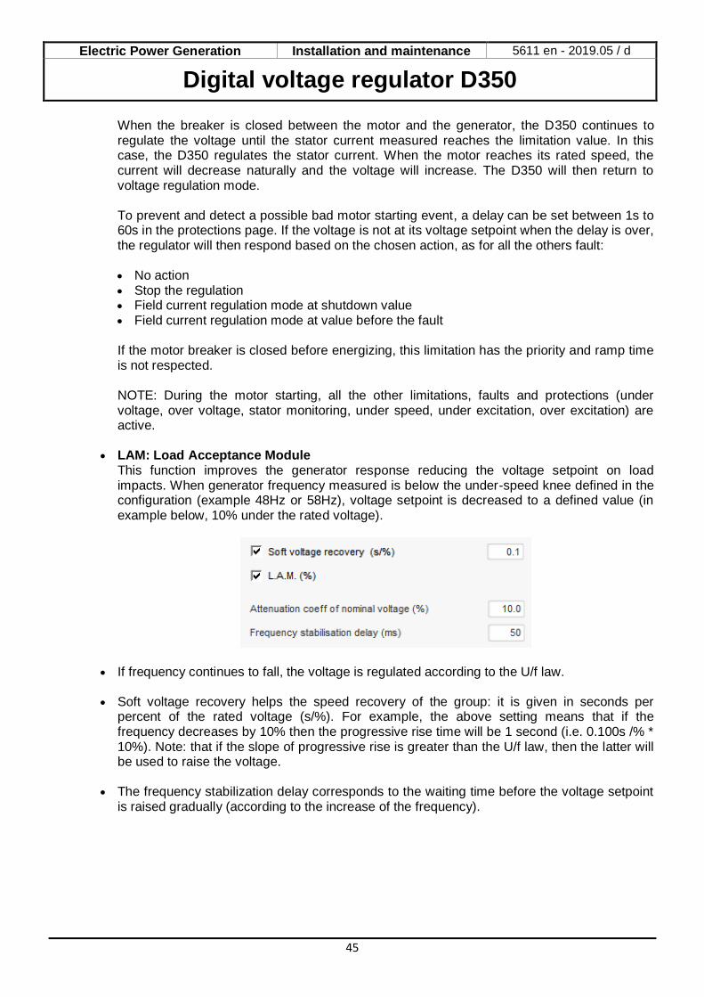
The compensation curve drawing changes as a function of the voltage setpoint.
NOTE: If load compensation has been enabled, it is no longer possible to have quadrature droop.
• Motor start: Select the box to enable the starting motor function, and give a percentage of
rated stator current. This function is active only in voltage regulation mode and allows limiting the stator current at a defined value.
Electric Power Generation Installation and maintenance 5611 en - 2019.05 / d
Digital voltage regulator D350
45
When the breaker is closed between the motor and the generator, the D350 continues to regulate the voltage until the stator current measured reaches the limitation value. In this case, the D350 regulates the stator current. When the motor reaches its rated speed, the current will decrease naturally and the voltage will increase. The D350 will then return to voltage regulation mode. To prevent and detect a possible bad motor starting event, a delay can be set between 1s to 60s in the protections page. If the voltage is not at its voltage setpoint when the delay is over, the regulator will then respond based on the chosen action, as for all the others fault: • No action • Stop the regulation • Field current regulation mode at shutdown value • Field current regulation mode at value before the fault If the motor breaker is closed before energizing, this limitation has the priority and ramp time is not respected. NOTE: During the motor starting, all the other limitations, faults and protections (under voltage, over voltage, stator monitoring, under speed, under excitation, over excitation) are active.
• LAM: Load Acceptance Module
This function improves the generator response reducing the voltage setpoint on load impacts. When generator frequency measured is below the under-speed knee defined in the configuration (example 48Hz or 58Hz), voltage setpoint is decreased to a defined value (in example below, 10% under the rated voltage).
• If frequency continues to fall, the voltage is regulated according to the U/f law.
• Soft voltage recovery helps the speed recovery of the group: it is given in seconds per percent of the rated voltage (s/%). For example, the above setting means that if the frequency decreases by 10% then the progressive rise time will be 1 second (i.e. 0.100s /% * 10%). Note: that if the slope of progressive rise is greater than the U/f law, then the latter will be used to raise the voltage.
• The frequency stabilization delay corresponds to the waiting time before the voltage setpoint is raised gradually (according to the increase of the frequency).
Electric Power Generation Installation and maintenance 5611 en - 2019.05 / d
Digital voltage regulator D350
46
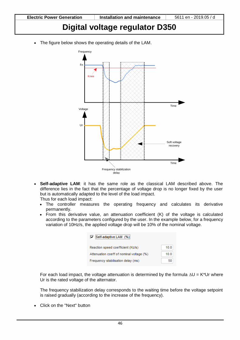
• The figure below shows the operating details of the LAM.
• Self-adaptive LAM: it has the same role as the classical LAM described above. The
difference lies in the fact that the percentage of voltage drop is no longer fixed by the user but is automatically adapted to the level of the load impact. Thus for each load impact: • The controller measures the operating frequency and calculates its derivative
permanently. • From this derivative value, an attenuation coefficient (K) of the voltage is calculated
according to the parameters configured by the user. In the example below, for a frequency variation of 10Hz/s, the applied voltage drop will be 10% of the nominal voltage.
For each load impact, the voltage attenuation is determined by the formula U = K*Ur where
Ur is the rated voltage of the alternator. The frequency stabilization delay corresponds to the waiting time before the voltage setpoint is raised gradually (according to the increase of the frequency).
• Click on the "Next" button
Frequency
VoltageTime
Time
Soft voltage
recovery
Frequency stabilization
delay
Knee
Electric Power Generation Installation and maintenance 5611 en - 2019.05 / d
Digital voltage regulator D350
47
Step 6c: Regulation of the field current (Manual mode)
• This regulation is used to control the value of the field current directly. It is mainly used during commissioning or as fallback mode if a measurement is incorrect on the AVR (alternator voltage measurement or alternator current measurement for example).
• It takes priority over the voltage regulation mode.
• The home reference point is determined by the drop-down list:
• By a fixed value in the configuration.
• By an analog input with a range to be defined.

Electric Power Generation Installation and maintenance 5611 en - 2019.05 / d
Digital voltage regulator D350
48
• If the “Analog input” option is selected, the “Setpoint from analog input” part is enabled further down. Select the desired analog input box, determine its mode (0/10 V or potentiometer) and the excitation current values at 0% and 100%.
NOTE: By moving the cursor, it is possible to view the field current reference (blue line) on the graph located on the right of the shape.
• The “Follower mode” function, when switching from a regulation mode to manual mode, allows the field current measurement to be used as a reference. This prevents any visible “jumps” on the machine output voltage.
Electric Power Generation Installation and maintenance 5611 en - 2019.05 / d
Digital voltage regulator D350
49
Step 7: Setting the PID gains
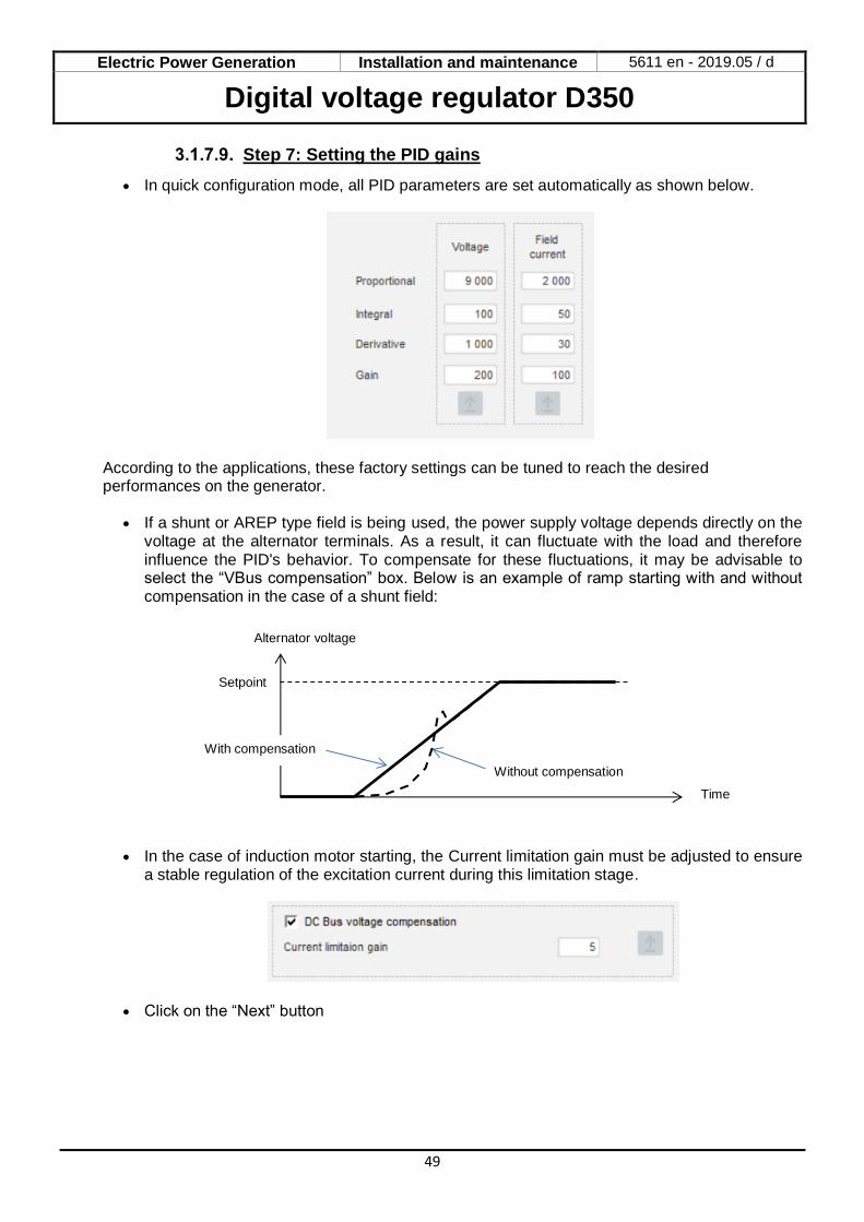
• In quick configuration mode, all PID parameters are set automatically as shown below.
According to the applications, these factory settings can be tuned to reach the desired performances on the generator.
• If a shunt or AREP type field is being used, the power supply voltage depends directly on the voltage at the alternator terminals. As a result, it can fluctuate with the load and therefore influence the PID's behavior. To compensate for these fluctuations, it may be advisable to select the “VBus compensation” box. Below is an example of ramp starting with and without compensation in the case of a shunt field:
• In the case of induction motor starting, the Current limitation gain must be adjusted to ensure a stable regulation of the excitation current during this limitation stage.
• Click on the “Next” button
Time
Alternator voltage
Setpoint
Without compensation
With compensation
Electric Power Generation Installation and maintenance 5611 en - 2019.05 / d
Digital voltage regulator D350
50
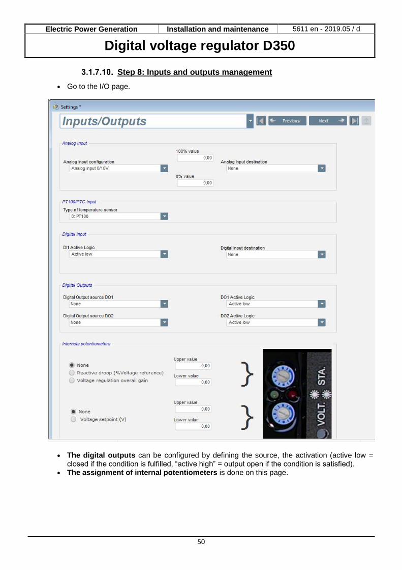
Step 8: Inputs and outputs management
• Go to the I/O page.
• The digital outputs can be configured by defining the source, the activation (active low = closed if the condition is fulfilled, “active high” = output open if the condition is satisfied).
• The assignment of internal potentiometers is done on this page.
Electric Power Generation Installation and maintenance 5611 en - 2019.05 / d
Digital voltage regulator D350
51
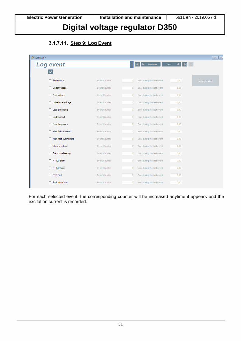
Step 9: Log Event
For each selected event, the corresponding counter will be increased anytime it appears and the excitation current is recorded.

Electric Power Generation Installation and maintenance 5611 en - 2019.05 / d
Digital voltage regulator D350
52
Step 10: The Second Configuration
This function is usually known as the “50/60Hz switch function”, but it offers much more features and flexibilities.
• Activate the Second configuration. • Select the parameters which will be affected when switching to that second configuration. In the
example above, we define a new frequency knee at 58Hz, a new voltage setpoint at 480V, the V/Hz slope is set to 1.5 and the voltage sensing is now done on the 3 phases of the generator.
• Back to the I/Os page, ones will see that the digital input DI1 is now assigned to that second configuration.
The activation of DI1 leads to the switching to the second configuration and its deactivation bring back the regulation to the base configuration.
NOTE: The switch is only taken into account at the regulation starting. Any activation or deactivation when the regulator is in operation will be ignored.
Electric Power Generation Installation and maintenance 5611 en - 2019.05 / d
Digital voltage regulator D350
53
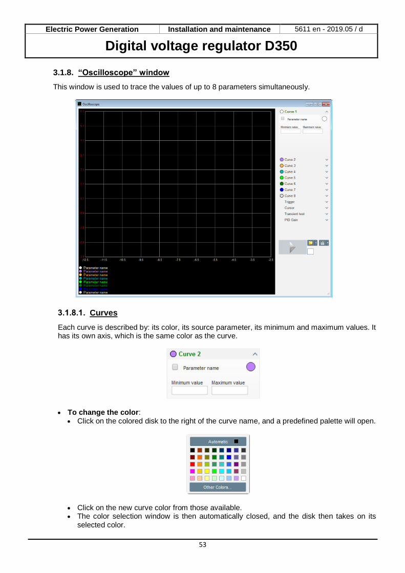
3.1.8. “Oscilloscope” window
This window is used to trace the values of up to 8 parameters simultaneously.
Curves
Each curve is described by: its color, its source parameter, its minimum and maximum values. It has its own axis, which is the same color as the curve.
• To change the color: • Click on the colored disk to the right of the curve name, and a predefined palette will open.
• Click on the new curve color from those available. • The color selection window is then automatically closed, and the disk then takes on its
selected color.

Electric Power Generation Installation and maintenance 5611 en - 2019.05 / d
Digital voltage regulator D350
54
• Should you wish to configure a color not in the palette, click on the “Other colors…” button. The palette is then transformed. Move the black cross to the selected color or fill in the text boxes (each value between 0 and 255) to define the RGB color values. Then click “OK”.
NB: When you no longer wish to change the color, just click outside the palette. It will close automatically.
• Select a parameter to plot • Click on the tick box.
• If the box was already selected, a confirmation message appears. On clicking “Yes”, a window opens with the list of parameters.
• If the box was not already selected, the window with the list of parameters opens directly.
• Select the parameter you wish to track from the drop-down list. This parameter can be an analog or digital value (regulation mode for example).
• Click “OK” to use the selected parameter, or “Cancel” if you don't wish to change anything.
• Refine the plotting range: change the minimum and maximum values if necessary. These
values are taken into account and the trace is re-scaled as soon as one of the boxes is exited or the keypad “Enter” key is pressed.
Electric Power Generation Installation and maintenance 5611 en - 2019.05 / d
Digital voltage regulator D350
55
When the monitor is on, the current value appears in square brackets.
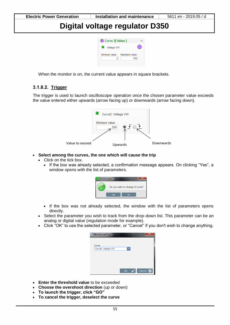
Trigger
The trigger is used to launch oscilloscope operation once the chosen parameter value exceeds the value entered either upwards (arrow facing up) or downwards (arrow facing down).
• Select among the curves, the one which will cause the trip
• Click on the tick box. • If the box was already selected, a confirmation message appears. On clicking “Yes”, a
window opens with the list of parameters.
• If the box was not already selected, the window with the list of parameters opens directly.
• Select the parameter you wish to track from the drop-down list. This parameter can be an analog or digital value (regulation mode for example).
• Click “OK” to use the selected parameter, or “Cancel” if you don't wish to change anything.
• Enter the threshold value to be exceeded • Choose the overshoot direction (up or down) • To launch the trigger, click “GO” • To cancel the trigger, deselect the curve
Downwards Upwards Value to exceed
Electric Power Generation Installation and maintenance 5611 en - 2019.05 / d
Digital voltage regulator D350
56
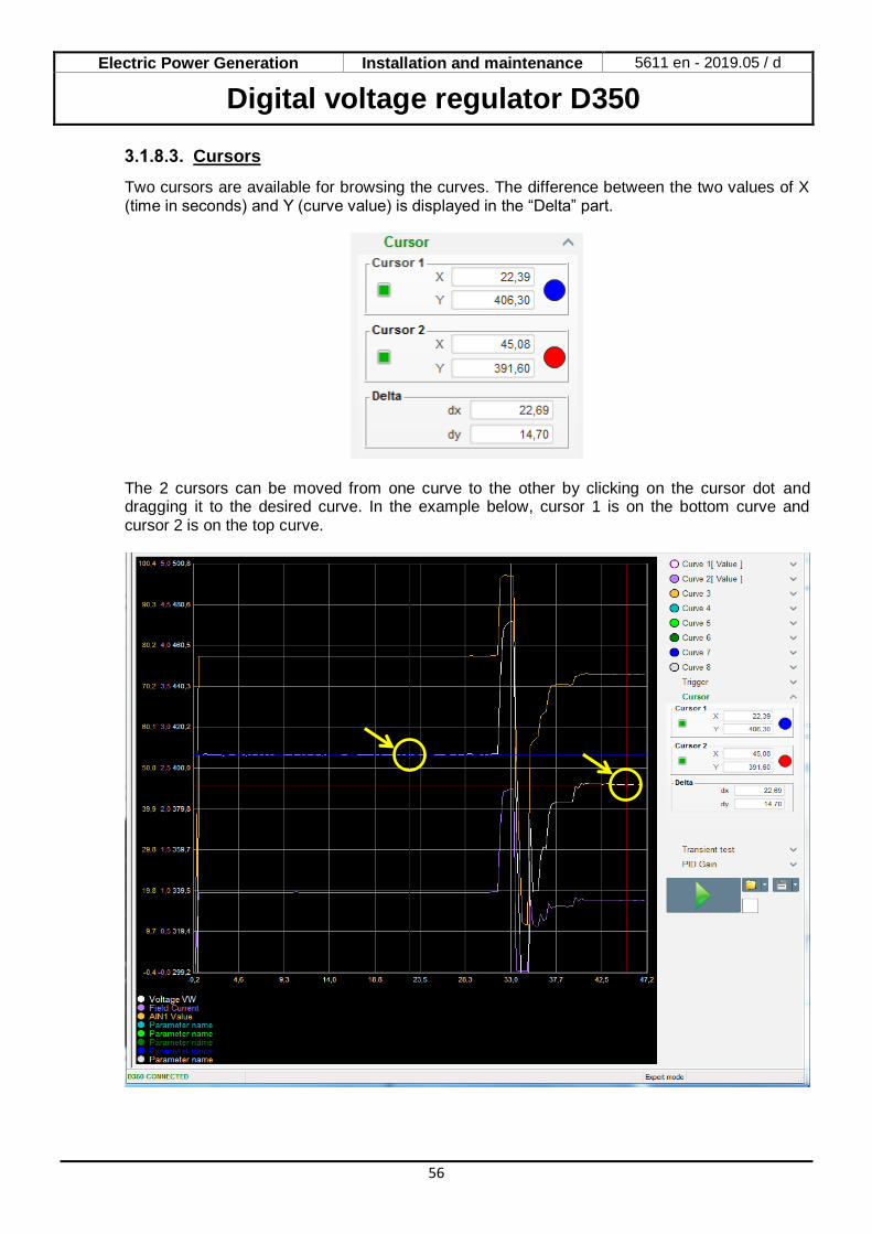
Cursors
Two cursors are available for browsing the curves. The difference between the two values of X (time in seconds) and Y (curve value) is displayed in the “Delta” part.
The 2 cursors can be moved from one curve to the other by clicking on the cursor dot and dragging it to the desired curve. In the example below, cursor 1 is on the bottom curve and cursor 2 is on the top curve.

Electric Power Generation Installation and maintenance 5611 en - 2019.05 / d
Digital voltage regulator D350
57
Transient test
The transient test is used to check the PID response when changing the voltage reference. It is divided into 5 steps maximum, each of which can take a different reference value. The PID parameters can be changed directly when the command is sent. • Click on the “Start a transient test” button. The following window opens:
• To configure your transient test: • Select between 1 and 5 steps by clicking on the corresponding tick box • For each selected step, define the reference value • Define the time between each step
• The PID values can be changed in order to adjust the gains. Once the parameters have been set, click “OK”. The test then starts. Steps in progress are shown by the reference turning green.
NOTE: • This test can be stopped at any time by clicking on the “Stop the transient test”
button. The display then reverts to the original reference. • Transient tests cannot be performed if the control reference input is controlled by an
analog input, as this has priority. • During this transient test, the defined minimum and maximum upper and lower limits
are not exceeded.
Electric Power Generation Installation and maintenance 5611 en - 2019.05 / d
Digital voltage regulator D350
58
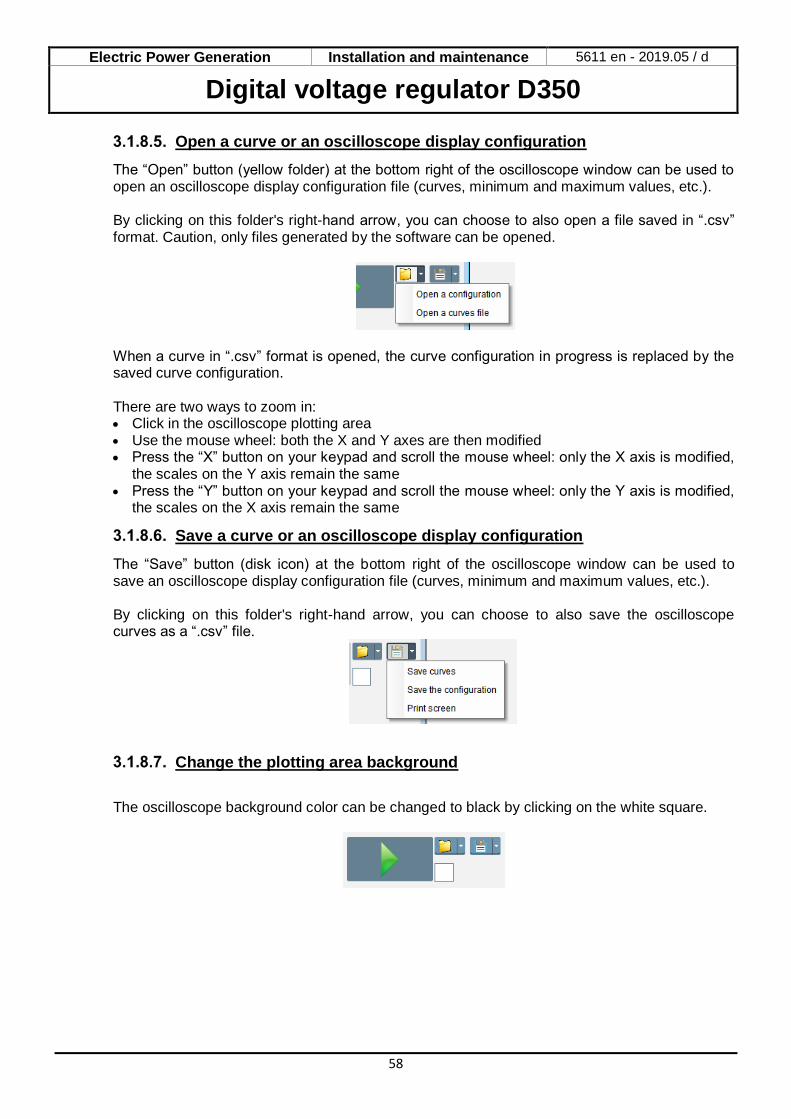
Open a curve or an oscilloscope display configuration
The “Open” button (yellow folder) at the bottom right of the oscilloscope window can be used to open an oscilloscope display configuration file (curves, minimum and maximum values, etc.). By clicking on this folder's right-hand arrow, you can choose to also open a file saved in “.csv” format. Caution, only files generated by the software can be opened.
When a curve in “.csv” format is opened, the curve configuration in progress is replaced by the saved curve configuration. There are two ways to zoom in: • Click in the oscilloscope plotting area • Use the mouse wheel: both the X and Y axes are then modified • Press the “X” button on your keypad and scroll the mouse wheel: only the X axis is modified,
the scales on the Y axis remain the same • Press the “Y” button on your keypad and scroll the mouse wheel: only the Y axis is modified,
the scales on the X axis remain the same
Save a curve or an oscilloscope display configuration
The “Save” button (disk icon) at the bottom right of the oscilloscope window can be used to save an oscilloscope display configuration file (curves, minimum and maximum values, etc.). By clicking on this folder's right-hand arrow, you can choose to also save the oscilloscope curves as a “.csv” file.
Change the plotting area background
The oscilloscope background color can be changed to black by clicking on the white square.
Electric Power Generation Installation and maintenance 5611 en - 2019.05 / d
Digital voltage regulator D350
59
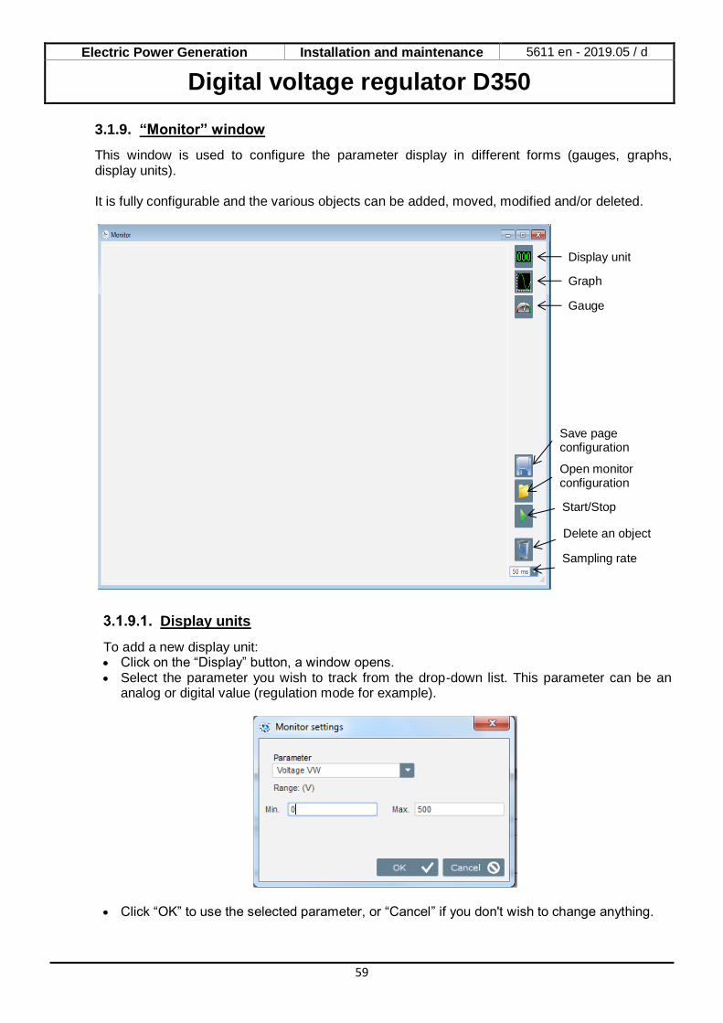
3.1.9. “Monitor” window
This window is used to configure the parameter display in different forms (gauges, graphs, display units). It is fully configurable and the various objects can be added, moved, modified and/or deleted.
Display units
To add a new display unit: • Click on the “Display” button, a window opens. • Select the parameter you wish to track from the drop-down list. This parameter can be an
analog or digital value (regulation mode for example).
• Click “OK” to use the selected parameter, or “Cancel” if you don't wish to change anything.
Display unit
Graph
Gauge
Save page configuration
Open monitor configuration
Start/Stop
Delete an object
Sampling rate
Electric Power Generation Installation and maintenance 5611 en - 2019.05 / d
Digital voltage regulator D350
60
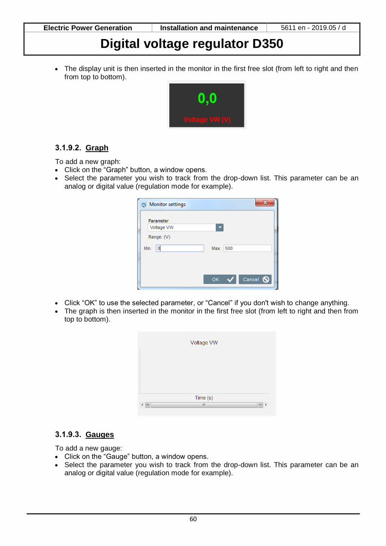
• The display unit is then inserted in the monitor in the first free slot (from left to right and then from top to bottom).
Graph
To add a new graph: • Click on the “Graph” button, a window opens. • Select the parameter you wish to track from the drop-down list. This parameter can be an
analog or digital value (regulation mode for example).
• Click “OK” to use the selected parameter, or “Cancel” if you don't wish to change anything. • The graph is then inserted in the monitor in the first free slot (from left to right and then from
top to bottom).
Gauges
To add a new gauge: • Click on the “Gauge” button, a window opens. • Select the parameter you wish to track from the drop-down list. This parameter can be an
analog or digital value (regulation mode for example).
Electric Power Generation Installation and maintenance 5611 en - 2019.05 / d
Digital voltage regulator D350
61
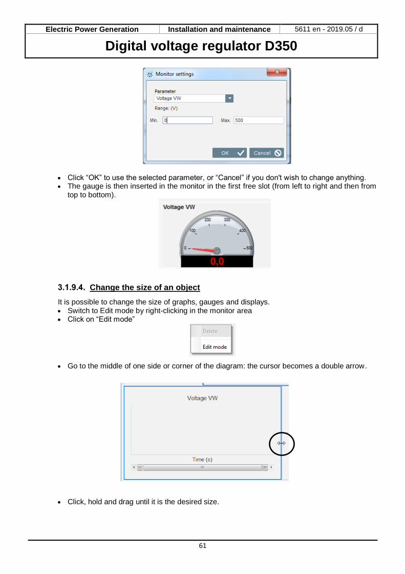
• Click “OK” to use the selected parameter, or “Cancel” if you don't wish to change anything. • The gauge is then inserted in the monitor in the first free slot (from left to right and then from
top to bottom).
Change the size of an object
It is possible to change the size of graphs, gauges and displays. • Switch to Edit mode by right-clicking in the monitor area • Click on “Edit mode”
• Go to the middle of one side or corner of the diagram: the cursor becomes a double arrow.
• Click, hold and drag until it is the desired size.

Electric Power Generation Installation and maintenance 5611 en - 2019.05 / d
Digital voltage regulator D350
62
Exit “Edit mode” either by pressing the “Esc” key or by right-clicking in the monitor area and deselecting “Edit mode”.
Delete an object
To delete an object (display unit, graph, gauge, etc.): • Switch to Edit mode by right-clicking in the monitor area • Click on “Edit mode”
• A grid then appears indicating the position of the various objects • Right-click on the display unit you wish to delete • Click “Delete”
Exit “Edit mode” either by pressing the “Esc” key or by right-clicking in the monitor area and deselecting “Edit mode”.
Save a monitor configuration
A monitor configuration can be saved in order to be reused later. Click on the “Save” button and a window will open. Give the name of the desired monitor configuration, and select “Save”.
Open a monitor configuration
Click on the “Open” button to retrieve a monitor configuration and a window will open. Select the desired monitor configuration, and select “Open”.
Electric Power Generation Installation and maintenance 5611 en - 2019.05 / d
Digital voltage regulator D350
63
3.2. Operations as analogue AVR
The D350 can be used as a simple analogue AVR. Hereafter are the available features that can be used or adjusted without any computer.
3.2.1. Voltage setting
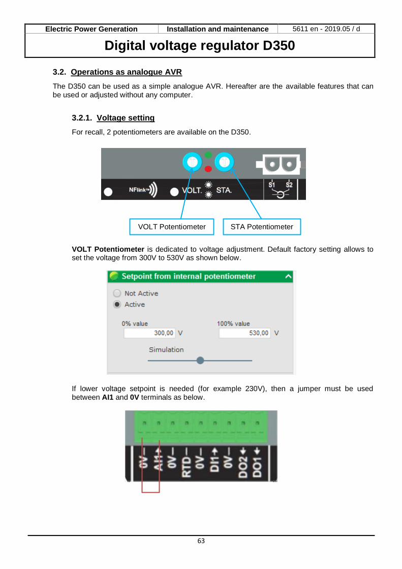
For recall, 2 potentiometers are available on the D350.
VOLT Potentiometer is dedicated to voltage adjustment. Default factory setting allows to set the voltage from 300V to 530V as shown below.
If lower voltage setpoint is needed (for example 230V), then a jumper must be used between AI1 and 0V terminals as below.
STA Potentiometer VOLT Potentiometer
Electric Power Generation Installation and maintenance 5611 en - 2019.05 / d
Digital voltage regulator D350
64
3.2.2. Stability setting
STA Potentiometer is dedicated to the stability setting. With factory settings, counter-clockwise corresponds to low dynamics performance and full-clockwise will lead to high dynamics performances. In general, potentiometer in middle position suits most of the cases.
3.2.3. Droop compensation
For parallel operation between generators, the default setting for droop compensation is 3%.
The default configuration is done with 1A secondary CT connected on the AVR terminals S1-S2.
NOTE: If there is a need to use for example a 5A secondary CT, then the D350 must be configured accordingly by using the NFLink cable.
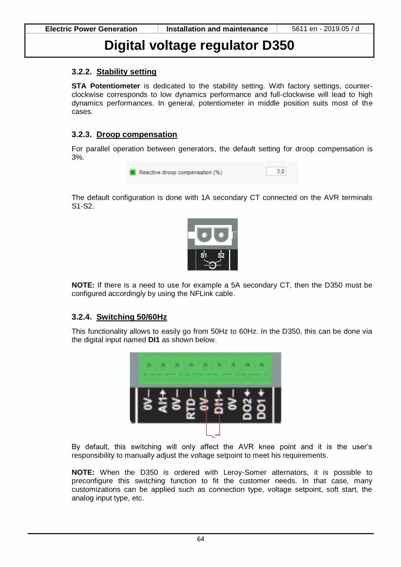
3.2.4. Switching 50/60Hz
This functionality allows to easily go from 50Hz to 60Hz. In the D350, this can be done via the digital input named DI1 as shown below.
By default, this switching will only affect the AVR knee point and it is the user’s responsibility to manually adjust the voltage setpoint to meet his requirements. NOTE: When the D350 is ordered with Leroy-Somer alternators, it is possible to preconfigure this switching function to fit the customer needs. In that case, many customizations can be applied such as connection type, voltage setpoint, soft start, the analog input type, etc.
Electric Power Generation Installation and maintenance 5611 en - 2019.05 / d
Digital voltage regulator D350
65
3.3. Tips and tricks
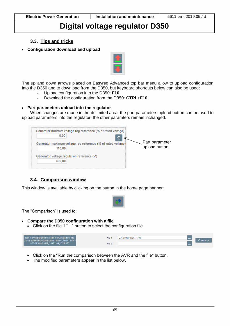
• Configuration download and upload
The up and down arrows placed on Easyreg Advanced top bar menu allow to upload configuration into the D350 and to download from the D350, but keyboard shortcuts below can also be used:
- Upload configuration into the D350: F10
- Download the configuration from the D350: CTRL+F10
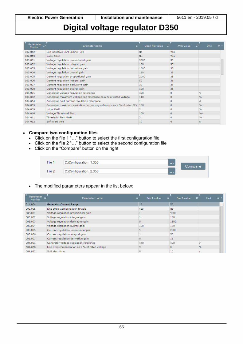
• Part parameters upload into the regulator When changes are made in the delimited area, the part parameters upload button can be used to
upload parameters into the regulator; the other paramters remain inchanged.
3.4. Comparison window
This window is available by clicking on the button in the home page banner:
The “Comparison” is used to: • Compare the D350 configuration with a file
• Click on the file 1 “…” button to select the configuration file.
• Click on the “Run the comparison between the AVR and the file" button. • The modified parameters appear in the list below.
Part parameter upload button
Electric Power Generation Installation and maintenance 5611 en - 2019.05 / d
Digital voltage regulator D350
66
• Compare two configuration files
• Click on the file 1 “…” button to select the first configuration file • Click on the file 2 “…” button to select the second configuration file • Click on the “Compare” button on the right
• The modified parameters appear in the list below:
Electric Power Generation Installation and maintenance 5611 en - 2019.05 / d
Digital voltage regulator D350
67
4. APPENDICES
4.1. Vector permutations
When the stator current measurement CT is wired up, the vector permutations can compensate for voltage measurement and current measurement transformer layouts which generate malfunction of the reactive droop compensation. The table below gives the possible permutations according to the phase used for the stator current measurement CT.
Position of stator current measurement
CT
Alternator direction of rotation
(a/c IEC 60034-1)
Alternator voltage measurement
AVR terminals U V W
Phase U (standard)
Clockwise
Alternator phases (three-phase measurement) U V W
Alternator phases (phase/phase single-phase measurement)
- V W
Anti-clockwise
Alternator phases (three-phase measurement) W V U
Alternator phases (phase/phase single-phase measurement)
- W V
Phase V
Clockwise
Alternator phases (three-phase measurement) V W U
Alternator phases (phase/phase single-phase measurement)
- W U
Anti-clockwise
Alternator phases (three-phase measurement) U W V
Alternator phases (phase/phase single-phase measurement)
- U W
Phase W
Clockwise
Alternator phases (three-phase measurement) W U V
Alternator phases (phase/phase single-phase measurement)
- U V
Anti-clockwise
Alternator phases (three-phase measurement) V U W
Alternator phases (phase/phase single-phase measurement)
- V U
Electric Power Generation Installation and maintenance 5611 en - 2019.05 / d
Digital voltage regulator D350
68
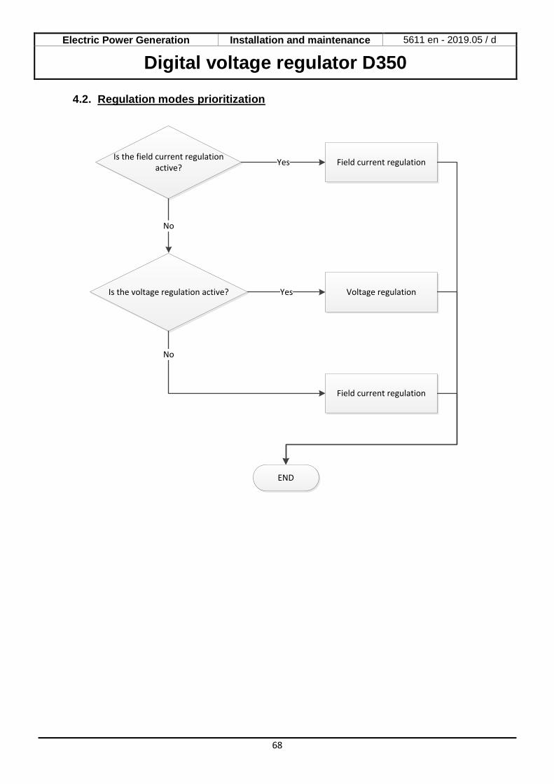
4.2. Regulation modes prioritization
Is the field current regulation active?
Is the voltage regulation active?
Field current regulation
Field current regulationYes
Voltage regulationYes
No
END
No
Electric Power Generation Installation and maintenance 5611 en - 2019.05 / d
Digital voltage regulator D350
69
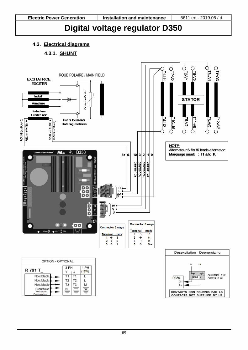
4.3. Electrical diagrams
4.3.1. SHUNT
Electric Power Generation Installation and maintenance 5611 en - 2019.05 / d
Digital voltage regulator D350
70
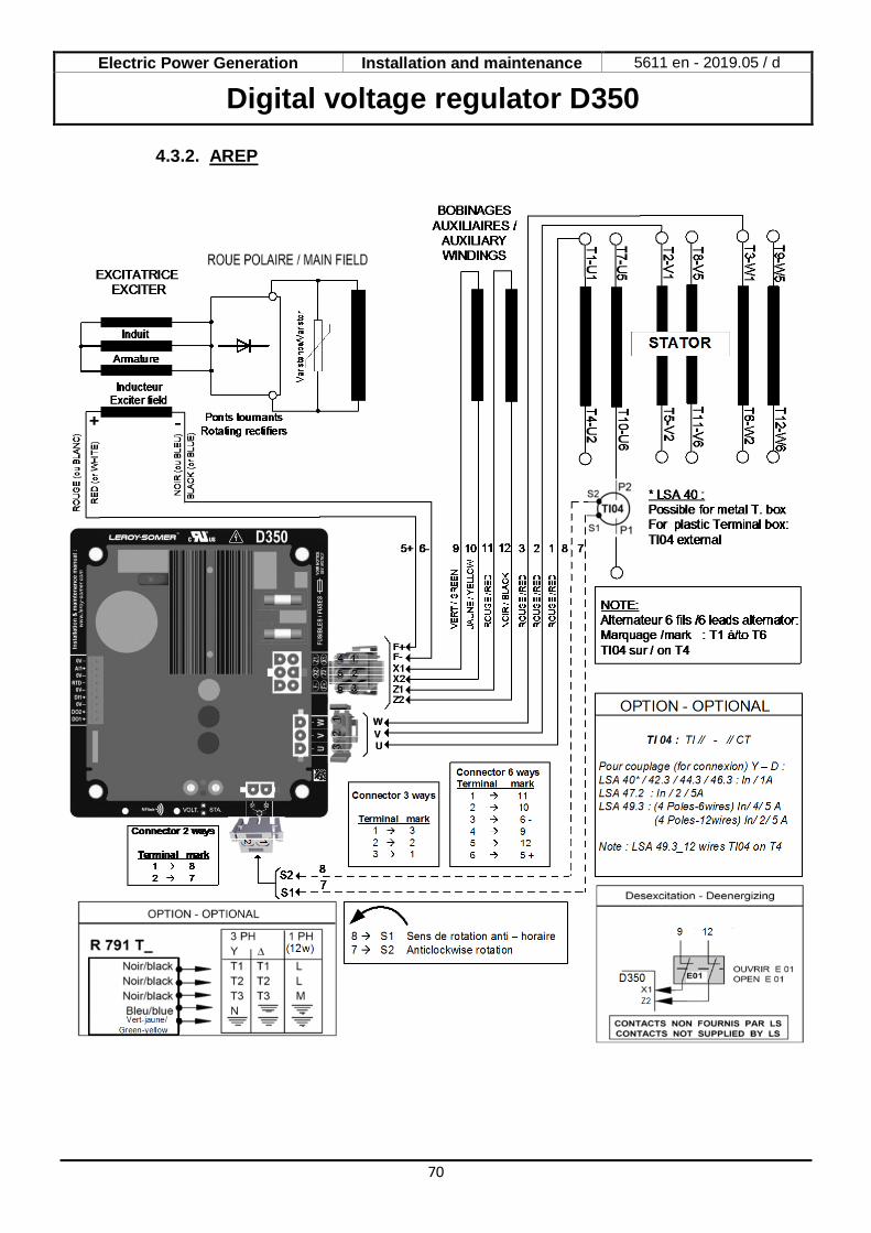
4.3.2. AREP

Electric Power Generation Installation and maintenance 5611 en - 2019.05 / d
Digital voltage regulator D350
71
4.3.3. PMG

Electric Power Generation Installation and maintenance 5611 en - 2019.05 / d
Digital voltage regulator D350
72
4.4. Faults trouble shouting
4.4.1. No Voltage
Field current mode active?
Voltage OK?
No
Change the AVR
No
No
END
Yes
No voltage
Switch to voltage mode
Rotating diodes OK?
Yes
Change the diodes
No
Exciter stator OK?
Change the Exciter stator
No
Yes
Yes
Electric Power Generation Installation and maintenance 5611 en - 2019.05 / d
Digital voltage regulator D350
73
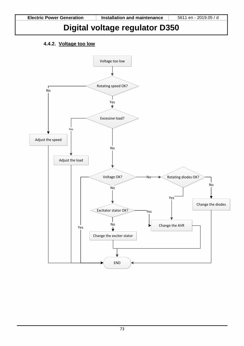
4.4.2. Voltage too low
Rotating speed OK?
Voltage OK?
Change the AVR
No
No
END
Yes
Voltage too low
Rotating diodes OK?
Yes
Change the diodes
No
Excitator stator OK?
Change the exciter stator
No
Yes
Adjust the speed
No
Excessive load?
No
Adjust the load
Yes
Yes
Electric Power Generation Installation and maintenance 5611 en - 2019.05 / d
Digital voltage regulator D350
74
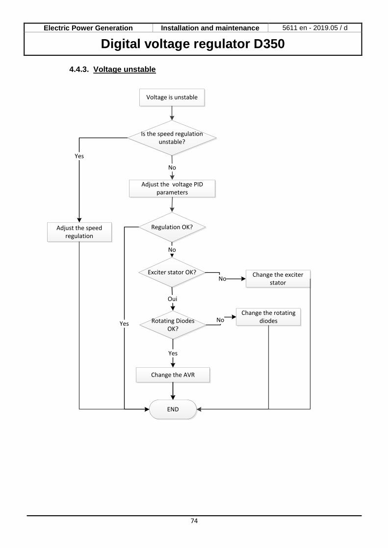
4.4.3. Voltage unstable
Is the speed regulation unstable?
END
No
Voltage is unstable
Change the AVR
Adjust the speed regulation
Yes
Regulation OK?
Yes
Adjust the voltage PID parameters
Change the exciter stator
Change the rotating diodes
Exciter stator OK?
Rotating Diodes OK?
No
Oui
Yes
No
No
Electric Power Generation Installation and maintenance 5611 en - 2019.05 / d
Digital voltage regulator D350
75
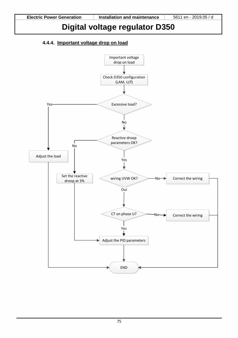
4.4.4. Important voltage drop on load
Excessive load?
wiring UVW OK?
Correct the wiring
No
Oui
END
No
Important voltage drop on load
CT on phase U?
Adjust the PID parameters
Yes
No
Adjust the load
Yes
Reactive droop parameters OK?
Yes
Set the reactive droop at 3%
No
Check D350 configuration (LAM, U/f)
Correct the wiring

Electric Power Generation Installation and maintenance 5611 en - 2019.05 / d
Digital voltage regulator D350
76
4.4.5. Time response too long
Is the speed regulation loop too slow?
END
No
Reponse time too long
Reduce the soft recovery parameter (%/s)
No
Adjust the speed regulator
Yes
Time response acceptable?
Yes
Adjust the voltage PID parameter
Electric Power Generation Installation and maintenance 5611 en - 2019.05 / d
Digital voltage regulator D350
77

Electric Power Generation Installation and maintenance 5611 en - 2019.05 / d
Digital voltage regulator D350
78

[email protected] www.lrsm.co/support
Design
Life Extension
Optimisation
Start-up
Operation
•Consulting & specification•Maintenance
contracts
•Reconditioning•System upgrade
•Monitoring•System audit
•Commissioning•Training
•Genuine spare parts•Repair services
Our worldwide service network of over 80 facilities is at your service.This local presence is our guarantee for fast and efficient repair, support and maintenance services.Trust your alternator maintenance and support to electric power generation experts. Our field personnel are 100% qualified and fully trained to operate in all environments and on all machine types.We have a deep understanding of alternator operation, providing the best value service to optimise your cost of ownership.
Where we can help:
Contact us:Americas: +1 (507) 625 4011Europe & Rest of the world: +33 238 609 908Asia Pacific: +65 6250 8488 China: +86 591 88373036India: +91 806 726 4867Middle East: +971 4 5687431 Scan the code or go to:
Service & Support

www.leroy-somer.com/epg
- 2019.05 / d
Linkedin.com/company/Leroy-SomerTwitter.com/Leroy_Somer_enFacebook.com/LeroySomer.Nidec.enYouTube.com/LeroySomerOfficiel
5611 en