Embed Size (px)
Citation preview

Directions for use
QUICKIE SALSA
IMPORTANT: DO NOT USE YOUR WHEELCHAIR UNTIL THIS MANUAL HAS BEEN READ AND UNDERSTOOD.
User Information
Intended use power wheel chairs:
Power wheelchairs are exclusively for a user who is unable to walk or has limited mobility, for their own personal use in- and outdoor. When an Attendant Control Module is fitted, the Power Wheelchair may be operated by an assistant on behalf of the user.When a Dual Control Module is fitted the Power Wheelchair may be operated by the user, or control may be switched to an assistant to operate on behalf of the user.
The maximum weight limit (includes both the user and any weight of accessories fitted to the wheelchair) is marked on the serial number label, which is affixed to the chassis of the chair.
The chair serial number is affixed also to the front page of the owners manual supplied with the wheelchair.
Warranty can only be taken on if the product is used under the specified conditions and for the intended purposes.
The intended lifetime of the wheelchair is 5 years. Please DO NOT use or fit any 3rd party components to the wheelchair unless they are officially approved by Sunrise Medical.
Area of applicationThe variety of fitting variants as well as the modular design mean that it can be used by those who cannot walk or have limited mobility e.g. because of:
• Paralysis• Loss of extremity (leg amputation)• Extremity defect deformity• Joint contractures/joint injuries• Strokes and brain injuries• Neurological disabilities (e.g. MS, Parkinson…)• Illnesses such as heart and circulation deficiencies, disturbance of equilibrium or cachexia as well as for elderly people who still have the strength in the upper body.• Persons who are mentally and physically able to control an input device to operate the chair and its functions in a safe way.
When considering provision, please also note the body size, weight including the distribution of body weight, the user’s physical and psychological constitution, the age of the user, their living conditions and their environment.If in doubt a health care professional should be involved to ensure the user is not exposed to unacceptable risks.
Sunrise Medical is ISO 9001 certified, which ensures quality at all stages of the development and production of this wheelchair.
Sunrise Medical declares under its sole responsibility that this product is in conformity with the requirements of the directive 93/42/EEC amended by 2007/47/EEC.”
Sunrise Medical declares that this product fulfils the performance requirements for a “Crash Test” to ISO 7176-19.

Table of contents1 Your Wheelchair 62 How to use this manual 6
2.1 Introduction .................................................................... 62.2 Guarantee ...................................................................... 62.3 Warranty conditions ........................................................ 6
3 Label explanations / Word definitions 73.1 Definitions of words used in this manual ........................ 73.2 Label explanations .................................................... 7 + 8
4 General safety warning and user tips 94.1 General warnings .......................................................... 94.2 Features and options .................................................... 94.3 Kerbs ............................................................................. 94.4 Routine service ............................................................. 94.5 Emergency freewheel ................................................... 94.6 EMC - Radio transmitting devices. ............................... 94.7 Emergency braking ....................................................... 94.8 Sharp turns ................................................................... 94.9 Batteries ........................................................................ 94.10 Tyres .............................................................................. 94.11 Weight limit .................................................................... 94.12 Wheelchair motors ...................................................... 104.13 Hot surfaces ................................................................ 104.14 Wheelchair range ........................................................ 104.15 Road caution ............................................................... 104.16 Adverse conditions ...................................................... 104.17 Ramps ......................................................................... 104.18 Transfer to and from the chair ..................................... 104.19 Lift and tilt modules ..................................................... 104.20 Anti-tips ....................................................................... 104.21 Use on a slope ............................................................ 104.22 Using a vehicle mounted passenger lift ..................... 114.23 Creep mode ................................................................ 114.24 Stability of your wheelchair ......................................... 114.25 Wheels ........................................................................ 114.26 Rear view mirror .......................................................... 114.27 Crutch holder .............................................................. 114.28 Lights and indicators ................................................... 114.29 Swing away tray .......................................................... 11 4.29.1 Seat stay ..................................................................... 114.30 Using a kerb climber ................................................... 124.31 Lap belt ........................................................................ 134.32 VR2 Controller ........................................................... 13
5 Preparing your wheelchair for use 145.1 Handling the wheelchair ................................................ 145.2 Preparation for transportation or storage ..................... 145.3 Re-Assembling ............................................................ 145.4 Emergency freewheel ............................................ 14 - 155.5 Drive wheel suspension Salsa...................................... 155.6 Control joystick unit position ......................................... 155.7 Getting ready to drive.................................................... 165.8 Armrests ................................................................. 16- 185.9 Legrests ................................................................ 19 - 20
6 Seating 216.1 Firm seat board ........................................................... 216.2 Seat cushions ............................................................. 216.3 Removable seat covers .............................................. 216.4 Standard backrest upholstery ..................................... 216.5 JAY backrests ............................................................. 216.6 Seat Height Adjustment .............................................. 216.7 Seat Width Adjustment ............................................... 216.8 Seat Depth Adjustment ............................................... 226.9 Backrest Angle Adjustment ........................................ 226.10 Back Height Adjustment ..................................... 22 - 246.11 Manual adjustable backrest (manual recline) ............. 24
6.12 Manual setting of the seat angle on the SALSA ......... 246.13 Headrest ...................................................................... 246.14 Powered Seating ......................................................... 25
7 The VR2 Hand Control series 26 - 287.1 VR2 .............................................................................. 267.2 VR2-L .......................................................................... 277.3 VR2 Dual control unit .................................................. 27
8 Troubleshooting using the VR2 Hand Control 299 Controller Mounts 30
9.1 General warnings ........................................................ 309.2 Attendant control ......................................................... 309.3 Parallel swing-away control ........................................ 30
10 Batteries and charging 3110.1 Batteries ...................................................................... 3110.2 Safety cut-outs ............................................................ 3110.3 General battery information ........................................ 3110.4 Maintenance free batteries ......................................... 3110.5 Battery care ................................................................. 3110.6 Maintenance free battery care plan ............................ 3110.7 General charger information ....................................... 3110.8 Charger safety features ...................................... 31 - 3210.9 Procedure for connecting the charger and charging .. 3210.10 Charger safety and caution notes ............................... 3210.11 The range of your vehicle ............................................ 3210.12 Common battery statements ...................................... 3210.13 Battery warranty .......................................................... 32
11 Transportation 33 - 3511.1 Transportation warnings: ............................................. 3311.2 Occupant restraint instructions ................................... 3311.3 Crash testing on the SALSA ...................................... 3411.4 The tie down label and placement ............................. 3411.5 Securing the wheelchair into the vehicle ................... 34 11.6 Salsa tie downs ........................................................... 35
12 Maintenance and Cleaning 3612.1 Tyre maintenance and pressures ................................ 3612.2 Tyre wear ..................................................................... 3612.3 Drive wheel tyre repair ................................................ 3612.4 Removing the castor wheel ........................................ 3612.5 Cleaning your wheelchair ........................................... 3612.6 Inspection of the upholstery / seating ........................ 3612.7 Cleaning seating ......................................................... 3612.8 Cleaning controls ........................................................ 3612.9 Lighting bulb exchange procedure ..................... 36 - 3712.10 Electrical connections ................................................. 3712.11 How to connect the cables to the batteries ................ 37 12.12 Controller access ........................................................ 3712.13 Storage ........................................................................ 3712.14 Authorised Sunrise Medical service agents ............... 3712.15 Recommended maintenance routines ................ 37 - 3812.16 Performance checks ................................................... 38
13 Specification sheets (EN 12184 & ISO 7176-15) 3914 Service History 4015 Disposal 4116 SALSA Battery Wiring Diagram 42
4 Quickie SALSA
EN
GLI
SH
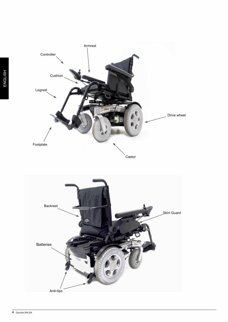
Armrest
Legrest
Controller
Cushion
Castor
Footplate
Drive wheel
Skirt Guard
Anti-tips
Backrest
Batteries
Quickie SALSA 5
EN
GLI
SH
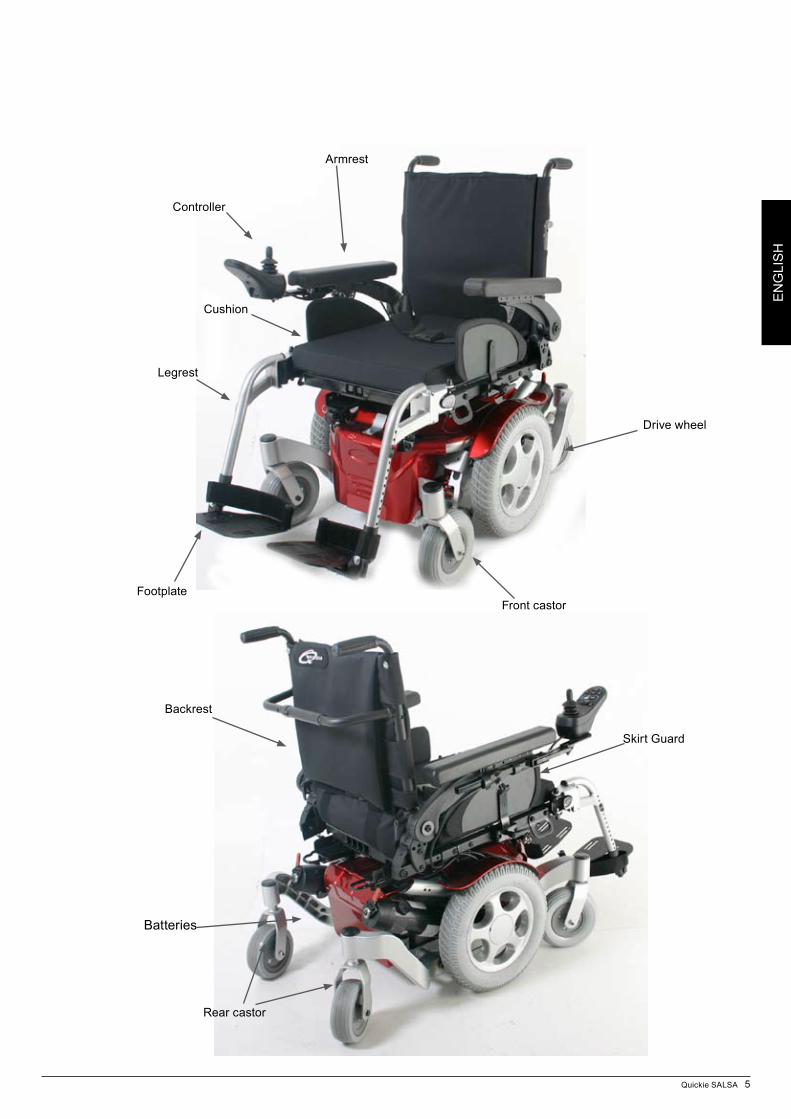
Armrest
Legrest
Controller
Cushion
Front castorFootplate
Drive wheel
Skirt Guard
Backrest
Batteries
Rear castor
6 Quickie SALSA
EN
GLI
SH
1 Your Wheelchair
We at Sunrise Medical want you to get the best out of your Salsa wheelchair. This Owner’s Manual will familiarise you with the chair and its features. It contains hints on everyday usage and general care in addition to information on the high quality standards which we adhere to and details about the guarantee.
Your wheelchair should be delivered fully assembled for your use; there are a wide range of components and adjustments available on the Salsa. For further information about these you should contact your Sunrise Medical authorised dealer.
Your wheelchair will reach you in excellent condition having been individually inspected before leaving our factory. Following the guidelines for maintenance and cleaning your wheelchair will maintain its first class condition and give you complete satisfaction.The Salsa has been designed for use by an individual on a daily basis. It is suitable for both indoor and outdoor use (Class B). It is only intended for use as a pavement vehicle, but may also be used when crossing between pavements.
This vehicle has been designed for a single occupant of limited mobility up to the weight of 140Kg (dependent on options chosen for your chair) who has the cognitive, physical and visual ability to control the vehicle safely on a maximum slope of 16% (9°). If you are in any doubt as to the suitability of the power chair, contact your local Sunrise Medical approved supplier for clarification, prior to commencing use.
It is very important to read the relevant section of the owner’s manual when making any minor adjustments. Contact your local Sunrise Medical authorised dealer for more complex adjustments.
If you have any queries about the use, maintenance or safety of your wheelchair, please contact your local Sunrise Medical authorised dealer. If you do not know of an authorised dealer in your area or have any other questions please write or telephone:
Sunrise Medical LTD. Sunrise Business Park High Street, Wollaston West Midlands DY8 4PS England Phone: +44 (0) 1384 44 66 88 Fax: +44 (0) 1384 44 66 99
Sunrise Medical is ISO 9001 certified, which ensures quality at all stages of the development and production of this wheelchair. This product is manufactured to comply with Medical Device Directive 93/42/EEC amended by 2007/47/EEC.
How to use this manual2 2.1 IntroductionPlease keep a note of your local authorised dealer address and telephone number in the space below.In the event of a breakdown, contact them and try to give all relevant details so they can help you quickly.The wheelchairs shown and described in this manual may not be exactly the same in every detail as your own model. However, all instructions are still entirely relevant, irrespective of detail differences.The manufacturer reserves the right to alter without notice any weights, measurements or other technical data shown in this manual. All figures, measurements and capacities shown in this manual are approximate and do not constitute specifications. For visual impaired people we have placed this document as a PDF on our website, please look at www.sunrisemedical.com.
2.2 GuaranteeThe guarantee form is included in the Sunrise Pack. Please fill in the relevant details and return to us to register your entitlement.
THIS IN NO WAY AFFECTS YOUR STATUTORY RIGHTS.2.3 Warranty conditions1) The repair or replacement will be carried out by an authorised Sunrise Medical dealer/service agent.
2) To apply the warranty conditions, should your wheelchair require attention under these arrangements, notify the designated Sunrise Medical service agent immediately giving full information about the nature of the difficulty. Should you be operating the wheelchair away from the locality of the designated Sunrise Medical service agent, work under the “Warranty Conditions” will be carried out by any other service agent designated by the manufacturer.
3) Should any part of the wheelchair require repair or replacement, as a result of a specific manufacturing or material defect, within twenty four months from the date on which the possession of the wheelchair was transferred to the original purchaser, and subject to it remaining within that ownership, the part or parts will be repaired or replaced completely free of charge if returned to the authorised service agent.
4) Any repaired or replaced part will benefit from these arrangements for the balance of the warranty period applicable to the wheelchair.5) Parts replaced after the original warranty has expired are covered for a further twelve months.
6) Items of a consumable nature will not generally be covered during the normal warranty period, unless such items have clearly suffered undue wear as a direct result of an original manufacturing defect. These items include amongst others upholstery, tyres, inner tubes and similar parts. On powered products this will also include batteries, motor brushes etc
7) The above warranty conditions apply to all wheelchair parts for models purchased at full retail price.8) Under normal circumstances, no responsibility will be accepted where the wheelchair has required repair or replacement as a direct result of:
a) The wheelchair or part not having been maintained or serviced in accordance with the manufacturer’s recommendations, as stated in the Owner’s Manual and/or Service Manual. Or failing to use only the specified original equipment parts.b) The wheelchair or part having been damaged by neglect, accident or improper use.c) The wheelchair or part having been altered from the manufacturer’s specifications, or repairs having been attempted prior to the service agent being notified.
Dealer signature and stamp
*
(
IMPORTANT: DO NOT USE YOUR WHEELCHAIR UNTIL THIS MANUAL HAS BEEN READ AND UNDERSTOOD.
Quickie SALSA 7
EN
GLI
SH
Label explanations / Word definitions3
3.1 Definitions of words used in this manual
Word Definition
Warning Advice to the user of a potential risk of injury if the advice is not followed
Note General advice or best practice
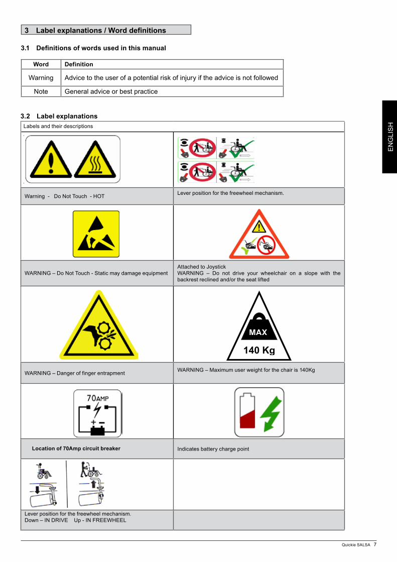
3.2 Label explanationsLabels and their descriptions
Warning - Do Not Touch - HOT Lever position for the freewheel mechanism.
WARNING – Do Not Touch - Static may damage equipmentAttached to JoystickWARNING – Do not drive your wheelchair on a slope with the backrest reclined and/or the seat lifted
WARNING – Danger of finger entrapment WARNING – Maximum user weight for the chair is 140Kg
Indicates battery charge point
Lever position for the freewheel mechanism.Down – IN DRIVE Up - IN FREEWHEEL
Location of 70Amp circuit breaker
140 Kg
MAX
8 Quickie SALSA
EN
GLI
SH
Labels and their descriptions
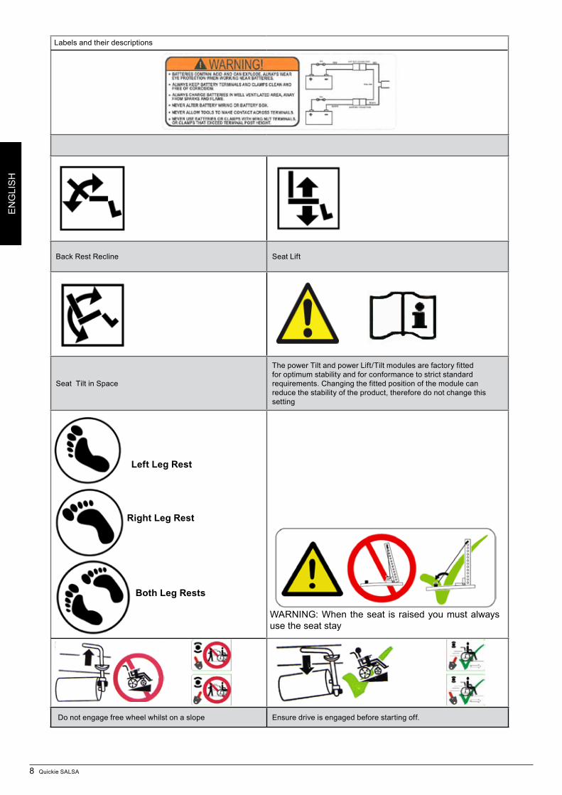
Back Rest Recline Seat Lift
Seat Tilt in Space
The power Tilt and power Lift/Tilt modules are factory fitted for optimum stability and for conformance to strict standard requirements. Changing the fitted position of the module can reduce the stability of the product, therefore do not change this setting
Do not engage free wheel whilst on a slope Ensure drive is engaged before starting off.
Left Leg Rest
Right Leg Rest
Both Leg Rests
WARNING: When the seat is raised you must always use the seat stay
Quickie SALSA 9
EN
GLI
SH
4 General safety warning and user tips
4.1 General warnings
• Alwaysensurethatyourwheelchair isswitchedoffbeforeattempting to mount or dismount.
• Alwaysensurethatyouareabletooperateallcontrolsfroma comfortable position. Paying attention to your posture is essential to ensure your continued comfort and well being.
• Alwaysmakesurethatyoucanbeseenclearly,especiallyif you intend using your wheelchair in poor light.
• This wheelchair has been built to match the needs of aparticular user. If used by another user then it may need to be adjusted and reprogrammed.
• Donotletchildrenorothersuseyourwheelchair.• All parts in direct contact with the user comply with EN
1021-1/2.• Beawarethatthewheelchairmaycometoasuddenstop
during operation.• Donotoperatethewheelchairifit isbehavingabnormally
or erratically.
4.2 Features and optionsSome of the options shown in this manual may not be available in your country and may also restrict the overall
physical limits of the standard product (e.g. max. speed, user weight limit, etc.). Those limitations are marked on the order form, in the technical manual and in this owner’s manual. For further information please consult your Sunrise Medical authorised dealer.
4.3 KerbsNever descend a kerb Forwards with a RWD chair. Please read carefully the section 4.30. on kerb climbing in this
manual before attempting to mount and dismount any kerbs in your wheelchair.Do not attempt to climb or descend a series of steps. It is unsafe to do so and could cause personal injury or damage the chair. The Salsa has only been designed to climb a single step or kerb.
4.4 Routine serviceThe recommended service interval is one year. (See service history table in section 14).
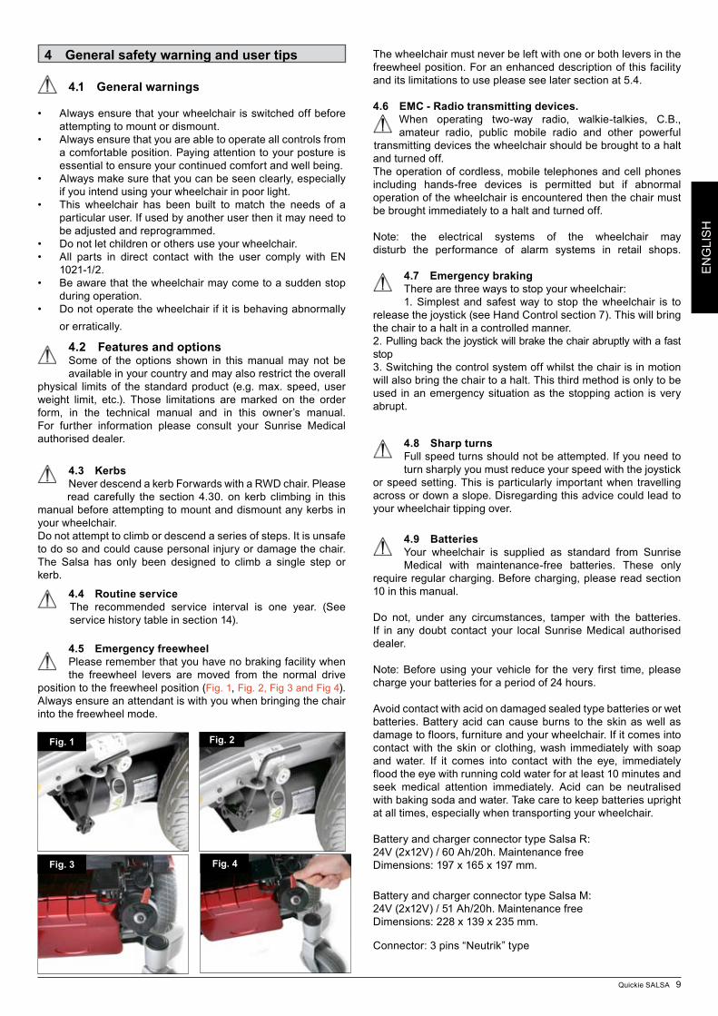
4.5 Emergency freewheelPlease remember that you have no braking facility when the freewheel levers are moved from the normal drive
position to the freewheel position (Fig. 1, Fig. 2, Fig 3 and Fig 4). Always ensure an attendant is with you when bringing the chair into the freewheel mode.
The wheelchair must never be left with one or both levers in the freewheel position. For an enhanced description of this facility and its limitations to use please see later section at 5.4.
4.6 EMC - Radio transmitting devices.When operating two-way radio, walkie-talkies, C.B., amateur radio, public mobile radio and other powerful
transmitting devices the wheelchair should be brought to a halt and turned off.The operation of cordless, mobile telephones and cell phones including hands-free devices is permitted but if abnormal operation of the wheelchair is encountered then the chair must be brought immediately to a halt and turned off.
Note: the electrical systems of the wheelchair may disturb the performance of alarm systems in retail shops.
4.7 Emergency brakingThere are three ways to stop your wheelchair:1. Simplest and safest way to stop the wheelchair is to
release the joystick (see Hand Control section 7). This will bring the chair to a halt in a controlled manner.2. Pulling back the joystick will brake the chair abruptly with a fast stop3. Switching the control system off whilst the chair is in motion will also bring the chair to a halt. This third method is only to be used in an emergency situation as the stopping action is very abrupt.
4.8 Sharp turnsFull speed turns should not be attempted. If you need to turn sharply you must reduce your speed with the joystick
or speed setting. This is particularly important when travelling across or down a slope. Disregarding this advice could lead to your wheelchair tipping over.
4.9 BatteriesYour wheelchair is supplied as standard from Sunrise Medical with maintenance-free batteries. These only
require regular charging. Before charging, please read section 10 in this manual.
Do not, under any circumstances, tamper with the batteries. If in any doubt contact your local Sunrise Medical authorised dealer.
Note: Before using your vehicle for the very first time, please charge your batteries for a period of 24 hours.
Avoid contact with acid on damaged sealed type batteries or wet batteries. Battery acid can cause burns to the skin as well as damage to floors, furniture and your wheelchair. If it comes into contact with the skin or clothing, wash immediately with soap and water. If it comes into contact with the eye, immediately flood the eye with running cold water for at least 10 minutes and seek medical attention immediately. Acid can be neutralised with baking soda and water. Take care to keep batteries upright at all times, especially when transporting your wheelchair.
Battery and charger connector type Salsa R: 24V (2x12V) / 60 Ah/20h. Maintenance freeDimensions: 197 x 165 x 197 mm.
Battery and charger connector type Salsa M:24V (2x12V) / 51 Ah/20h. Maintenance freeDimensions: 228 x 139 x 235 mm.
Connector: 3 pins “Neutrik” type
Fig. 1 Fig. 2
Fig. 4Fig. 3
10 Quickie SALSA
EN
GLI
SH
trigger the self protect mechanism in the control system. If this occurs the control system will temporarily shut down to prevent damage to the electronics or the chair.
4.17 RampsWhen using a ramp, please ensure that it is capable of
taking the combined weight of the power chair and yourself. If a ramp is being used to load a chair into a vehicle, please ensure the ramp is properly secured to the vehicle. Always approach the ramp head-on and exercise caution. Note: Please ensure your ramp is suitable for the product you are transporting.
4.18 Transfer to and from the chairSunrise Medical recommend that you consult your healthcare professional for assistance in developing your
personal front or side transfer technique to best suit your needs and avoid any personal injury.Note: Ensure controller is switched off during transfers to avoid unintentional movement.
4.19 Lift and tilt modulesPlease be aware that the lift and tilt modules present a
trap hazard. Make sure that when operating the tilt and lift it is free from all clothing, hands, feet and other extremities to prevent injury.Do not drive on ramps or slopes with the seat tilted, reclined or raised. Before attempting to climb or descend a slope, return to an upright position. The power Tilt and power Lift/Tilt modules are factory fittedfor optimum stability and for conformance to strict standard requirements. Changing the fitted position of the module canreduce the stability of the product, therefore do not change this setting.
Risk of trapping fingers:The protection guard secures the moving parts within the lift / tilt mechanism. Although protected please be always carefulnottogetyourfingertrappedinthemechanism.It
is mandatory to re-install the protection guards as described in the Salsa technical manual after any service or repairs ot the lift / tilt module.
4.20 Anti-tipsMake sure that anti-tips are not damaged or worn before using your chair. Attendants must be aware of the location of the anti-tips
to prevent feet being trapped underneath causing injury.Attendants - Do not stand on the anti-tips, this could cause the wheelchair to become unstable.
4.21 Use on a slopeYour wheelchair has been designed and tested to allow
its use on slopes or gradients of up to 9° (16%). However, you have the option of adjusting your seating position with either a lift, tilt or recline or a combination of these options, then in certain circumstances your wheelchair could become unstable. Before attempting to climb or descend a slope or a kerb, caution should be taken when using weight shift options (e.g. powered tilt or recline) of the seat and/or your body for a counter balance weight. To improve stability lean forward when driving uphill, with the seat and back in an upright position. Alternatively sit in an upright position when travelling in a forward, downhill direction or tilt and/or recline the seat backwards.
We strongly recommend that you return the seat and back to an upright lowered position before attempting to climb or descend a slope. Failure to do this may cause the wheelchair to become unstable.
If you are in any doubt about the capabilities of your wheelchair on a slope then do not attempt to drive up or down the slope/kerb; try to find an alternative route.
4.10 TyresYour wheelchair tyres can wear depending on use. Check them regularly in accordance with the service instructions in this manual, especially the pressure of the tyres.
NEVER inflate the tyres using a garage forecourt airline, always use the pump provided.
4.11 Weight limit• The user plus items carried should never exceed atotal weight of 140Kg
• Neveruse this chair forweight training if the totalweight(user plus additional weights) exceeds a total weight of 140Kg
• Exceeding the weight limit is likely to damage the seat,frame or fasteners and may cause severe injury to you or others from chair failure
• Exceedingtheweightlimitwillvoidthewarranty.
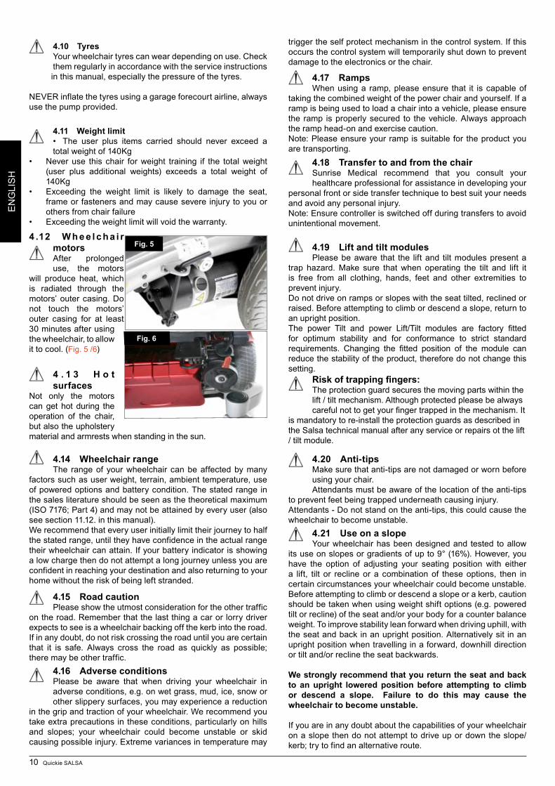
4 .12 W h e e l c h a i r motorsAfter prolonged use, the motors
will produce heat, which is radiat ed through the motors’ outer casing. Do not touch the motors’ outer casing for at least 30 minutes after using the wheelchair, to allow it to cool. (Fig. 5 /6)
4 . 1 3 H o t surfaces
Not only the motors can get hot during the operation of the chair, but also the upholstery material and armrests when standing in the sun.
4.14 Wheelchair rangeThe range of your wheelchair can be affected by many
factors such as user weight, terrain, ambient temperature, use of powered op tions and battery condition. The stated range in the sales literature should be seen as the theoretical maximum (ISO 7176; Part 4) and may not be attained by every user (also see section 11.12. in this manual).We recommend that every user initially limit their journey to half the stated range, until they have confidence in the actual range their wheelchair can attain. If your battery indicator is showing a low charge then do not attempt a long journey unless you are confident in reaching your destination and also returning to your home without the risk of being left stranded.
4.15 Road cautionPlease show the utmost consideration for the other traffic
on the road. Remember that the last thing a car or lorry driver expects to see is a wheelchair backing off the kerb into the road. If in any doubt, do not risk crossing the road until you are certain that it is safe. Always cross the road as quickly as possible; there may be other traffic.
4.16 Adverse conditionsPlease be aware that when driving your wheelchair in adverse conditions, e.g. on wet grass, mud, ice, snow or other slippery surfaces, you may experience a reduction
in the grip and traction of your wheelchair. We recommend you take extra precautions in these conditions, particularly on hills and slopes; your wheelchair could become unstable or skid causing possible injury. Extreme variances in temperature may
Fig. 5
Fig. 6
Quickie SALSA 11
EN
GLI
SH
4.21.1 Gradients: ascentsWhen going uphill, keep the chair moving. Steer by
moving the joystick from side to side. If you have stopped on a hill, you should start slowly. If necessary lean forward to prevent the tendency for the front wheels to lift. 4.21.2 Gradients: descentsOn descents, it is important not to let the wheelchair accelerate beyond its normal level of ground speed. In fact, it is safer to proceed slowly down steep descents (below the speed of 5kph) and stop, if any anxiety arises regarding directional control. If the chair picks up speed, centre the control to slow it or to stop all forward movement, then restart slowly and do not allow the speed to increase. The solid state controller has the benefit of a logic system that will help compensate when driving along a camber or up a hill. This is an added safety feature on your wheelchair. In addition of course, you may control the wheelchair speed by using the speed control.
4.22 Using a vehicle mounted passenger liftWheelchair lifts are used in vans, buses and buildings to
help you move from one level to another. Ensure that the user and all carers fully understand the lift manufacturer’s instructions for using the passenger lift. Never exceed the lift manufacturer’s recommended safe working load and load distribution guidance. Always turn off all power when you are on the lift. If you fail to do so, you may touch the joystick by accident and cause your chair to drive off the platform. Be aware that a rollstop at the end of the platform may not prevent this. Always position the user securely in the chair to help avoid falls while on the lift. Always ensure the chair is in drive mode when using passenger lift (wheels locked not in freewheel mode).
4.23 Creep modePlease ensure your backrest recline angle relative to floor
level, which is a combination of the back recline itself and the tilt angle, does not exceed 12° to drive the chair safely. If the tilt angle exceeds 9° the chair will the chair will automatically convert into “creep mode” which will allow you a maximum of 10% of the speed programmed in the profile.
WARNING - If you have a manual recline backrest on your wheelchair, please be aware that there will be no feedback system to the controller that tells it that the seat is in a reclined position. If you recline your backrest and attempt to drive, it will not go into ‘creep mode’, it will instead drive at full speed. This is especially dangerous when attempting to drive up a slope.
4.24 Stability of your wheelchairPlease follow the user instructions in this manual
regarding the use of seat lift and tilt modules and the use of your chair on a slope, other variables can affect your chair stability, including:- Movement of the user- Effects of the addition of accessories or other equipment- Inappropriate adjustments or modifications to the wheelchair
In some cases these issues are further compounded by the effects of the local environment such as:- Hills, Slopes, Ramps, Sloping pavements, Dropped kerbs.
Furthermore different body proportions of a wheelchair user affect stability for example:- Lower limb wasting or amputation, Obesity- Increased upper torso mass, Upper torso heightThe power Tilt and power Lift/Tilt modules are factory fittedfor optimum stability and for conformance to strict standard requirements. Changing the fitted position of the module canreduce the stability of the product, therefore do not change this setting.
4.25 WheelsAlways use the pump that is supplied with the chair, Never use a forecourt pump.
Inspect all tyres regularly for signs of wear.Do not drive over anything that could cause punctures in the tyres.Ensure that there are no objects in your path that could possibly become lodged in your chair mechanism or in the spokes of the rear wheels. This could cause the chair to come to a sudden stop.Riding over drains or grids could cause the wheelchair castors or wheels to become lodged, causing the chair to come to a sudden stop.Always maintain the correct pressure for the tyre. These are listed in section 12 of this manual.
Pneumatic Tyres with OKO fluid. The OKO fluid is only meant as a temporary repair to the tyre. It must be replaced or repaired as soon as possible.The OKO fluid is classified as non hazardous but may cause irritation to the skin with prolonged contact.4.26 Rear view mirrorTo avoid injury to people around you please be aware that the mirror protudes outside the space envelope of the chair and could cause injury to someone when driving past.The mirror must be used on the 10KPH model on UK roads.Always make sure that when using the mirror that it is clean and unbroken so that it does not impair your visibility.
4.27 Crutch holderMake sure that the crutch is securely fastened to the crutch holder.
Make sure that the crutch is not interfering with the mechanisms of the chair.Make sure that the crutch does not protrude from the chair.Do not attempt to remove the crutch whilst the chair is in motion. Always come to a complete stop and turn off the power to the controls before attempting to remove the crutch. This will avoid accidentally operating the chair.
4.28 Lights and indicatorsEnsure that the lights and indicators are functioning correctly and lenses are clean before going outdoors at night. Light assemblies can become very hot - Care must be taken if removing them for repair.
4.29 Swing away trayThe maximum weight allowed for the tray is 2.5kg.Do not overload the tray, this could cause the tray to break
or could cause the chair to become unstable.Do not leave lit cigarettes or other heat sources on the tray as this could cause the tray to deform and mark.Ensure that all extremities and clothing are free when positioning the tray for use.
4.29.1 Seat stayA seat stay is provided on your powerchair to provide access for service and maintenance. (see section 10 for additional info)WARNING - do not move the wheelchair with the seat stay in place and make sure you are on flat stable ground. Make sure that the plastic cap is securely fitted over the seat height tube.
First Aid measures for OKO fluidSkin - Wash skin with plenty of water Eyes - Immediately flood the eye with plenty of water for at least 5 minutes holding the eye open.Ingestion - Drink lots of water - Seek medical attention immediately.
12 Quickie SALSA
EN
GLI
SH
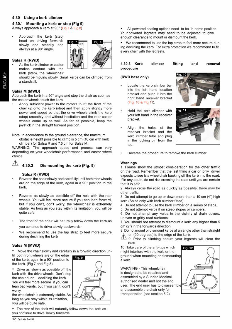
4.30 Using a kerb climber4.30.1 Mounting a kerb or step (Fig 9)Always approach a kerb at 90° (Fig 7 & Fig 8)
• Approach the kerb (step)head on driving forwards slowly and steadily and always at a 90° angle.
Salsa R (RWD)• Asthekerbclimberorcastor
makes contact with the kerb (step), the wheelchair should be moving slowly. Small kerbs can be climbed from a standstill.
Salsa M (MWD)Approach the kerb in a 90° angle and stop the chair as soon as the castor wheels touch the kerb.• Applysufficientpowertothemotorsto lift thefrontof the
chair up onto the kerb (step) and then apply slightly more power and speed so that the drive wheels climb the kerb (step) smoothly and without hesitation and the rear castor wheels come up as well. As far as possible, keep the joystick in the straight forward position.
Note: In accordance to the ground clearance, the maximum obstacle height possible to climb is 5 cm (10 cm with kerb climber) for Salsa R and 7.5 cm for Salsa M.
WARNING: The approach speed and process can vary depending on your wheelchair performance and castor wheel choice.
4.30.2 Dismounting the kerb (Fig. 9)
Salsa R (RWD)• Reversethechairslowlyandcarefullyuntilbothrearwheels
are on the edge of the kerb, again in a 90° position to the kerb.
• Reverse as slowly as possible off the kerb with the rearwheels. You will feel more secure if you can lean forward, but if you can’t, don’t worry, the wheelchair is extremely stable. As long as you stay within its limitation, you will be quite safe.
• Thefrontofthechairwillnaturallyfollowdownthekerbasyou continue to drive slowly backwards.
• We recommend to use the lap strap to feelmore secureduring declining the kerb
Salsa M (MWD)•Move the chair slowly and carefully in a forward direction un-til both front wheels are on the edge of the kerb, again in a 90° position to the kerb. (Fig 7 and Fig 8)• Drive as slowly as possible off the kerb with the drive wheels. Don’t stop the chair durin declining the kerb. You will feel more secure if you can lean bac wards, but if you can’t, don’t worry, the wheelchair is extremely stable. As long as you stay within its limitation, you will be quite safe.• The rear of the chair will naturally follow down the kerb as you continue to drive slowly forwards.
•All powered seating options need to be in home position. Your powered legrests may need to be adjusted to give enough clearance to mount or dismount the kerb. • We recommend to use the lap strap to feel more secure dur-ingdecliningthekerb.Forextraprotectionwerecommendtofitevery chair with the legrests.
4.30.3 Kerb climber fitting and removal procedure
(RWD base only)
• Locate thekerbclimberbarinto the left hand location bracket and push it into the right hand receiver bracket (Fig. 10 & Fig 11).
• Hold the kerb climber withyour left hand in the receiver bracket.
• Align the holes of thereceiver bracket and the kerb climber tube and plug in the locking pin from the top.
• Reversetheproceduretoremovethekerbclimber.
Warnings1. Please show the utmost consideration for the other traffic on the road. Remember that the last thing a car or lorry driver expects to see is a wheelchair backing off the kerb into the road. If in any doubt, do not risk crossing the road until you are certain that it is safe.2. Always cross the road as quickly as possible; there may be other traffic.3. Do not attempt to go up or down more than a 10 cm (4”) high kerb (Salsa only with kerb climber fitted).4. Do not attempt to use the kerb climber on a series of steps.5. Do not attempt kerbs if on steep slopes or cambers.6. Do not attempt any kerbs in the vicinity of drain covers, uneven or gritty road surfaces.7. You should not attempt to dismount a kerb any higher than 5 cm (2”) in the forwards direction.8. Do not mount or dismount kerbs at an angle other than straight
on (90 degrees) to the edge of the kerb.9. Prior to climbing ensure your legrests will clear the kerb.
10. Take care of the anti-tips which might interfere with the kerb or the ground when mounting or dismounting a kerb.
WARNING - This wheelchair is designed to be repaired and assembled by a Sunrise Medical authorised dealer and not the end user. The end user has to disassemble and assemble the chair only for transportation (see section 5.2).
Fig. 7 Fig. 8
Fig. 11
Fig. 10
Fig. 9
Fig. 12
Quickie SALSA 13
EN
GLI
SH
4.31 Lap beltThe lap belt kit. (Fig. 13).
Fastening the lap strap. Insert the 3 prong male buckle into the female buckle until a click is heard (Fig. 14)
To fit the lap strap.Place the strap loosely across the seat with the buckle closed.. (Fig. 15)
Pass the other ends of the strap through the gap between the backrest posts and the backrest upholstery as shown. (Fig. 16)
Ensure that the adjusters & buckles can be accessed & the strap is not twisted. Fit the eyelet over the rearmost bolt. Fit the plain washer, sprung washer & nut. Tighten with a 13.0mm spanner. Repeat for the other side. (Fig 17)
Ensure that the lap strap is tight enough to provide comfortable support. A simple measure is to keep a hands thickness between the body and lap strap. For safety, check the tension on the lap strap at least once day. (Fig 18)
Generally, the lap belt should be fixed so that the straps sit at an angle of approximately 45° (Fig. 19), and when correctly adjusted should not allow the user to slip down in the seat.
Warning - Always make sure that the lap strap is correctly secured and adjusted prior to use.A loose strap could cause the user to slip down and cause serious injury.Check lap strap and securing components at regular intervals for any signs of fray or damage. Replace if necessaryWhen servicing, check for correct operation of the release buckle and for any signs of wear on the material or plastic brackets
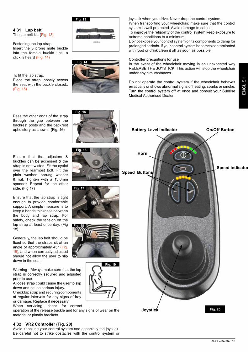
4.32 VR2 Controller (Fig. 20)Avoid knocking your control system and especially the joystick. Be careful not to strike obstacles with the control system or
joystick when you drive. Never drop the control system.When transporting your wheelchair, make sure that the control system is well protected. Avoid damage to cables.To improve the reliability of the control system keep exposure to extreme conditions to a minimum.Do not expose your control system or its components to damp for prolonged periods. If your control system becomes contaminated with food or drink clean it off as soon as possible.
Controller precautions for useIn the event of the wheelchair moving in an unexpected way RELEASE THE JOYSTICK. This action will stop the wheelchair under any circumstances
Do not operate the control system if the wheelchair behaves erratically or shows abnormal signs of heating, sparks or smoke. Turn the control system off at once and consult your Sunrise Medical Authorised Dealer.
Fig. 13
Fig. 14
Fig. 15
Fig. 16
Fig. 19
Battery Level Indicator On/Off Button
Horn
Speed IndicatorSpeed Buttons
Joystick
Fig. 17
Fig. 18
Fig. 20
14 Quickie SALSA
EN
GLI
SH
5 Preparing your wheelchair for use 5.1 Handling the wheelchairNote: To dismantle the chair for transport or storage no tools are required.List of components when dismantled (components below are related to the maximum detachable parts and dependent on the type of seating system chosen):1 pair of armrests1 pair of legrests, 1 backrest (Std. Rehab/comfort seat only)1 drive unit with seat frame
5.2 Preparation for transportation or storageFirst remove the legrests if swing away legrests are attached. Leave the armrests in the fold down position. (Fig.21,23) disconnect the Hand Control, (Fig.22), if necessary. Release and lift off the backrest at the frame. Now you can store the chassis part. By releasing the freewheel mechanism on the left and right side of the chassis you can move the drive unit as close as possible to the place you want to store it.You can also drive the base with the joystick up or down a ramp into and out of a car for transportation. Make sure, when the chair is stored or left in the car or anywhere else, the controller is switched off and the freewheel mechanisms are engaged.If there is a need to lift the drive unit the big side frame tubes should be used. Caution should be taken if the chair is in freewheel.
To remove the control pod.To remove the control pod you have to access the motor controller through the plastic cover between the castor wheels and remove the square remote control connector.Place the control pod & arm in a safe place until required.To reconnect the hand control just use the process in reverse.
5.3 Re-Assembling Replace the backrest into the receivers and tighten the lever screws carefully. If required reconnect the remote controller. Attach the hangers. Make sure your freewheel mechanisms are engaged. Now you are ready to drive the chair.
WARNING - Never lift the wheelchair by the armrests or the leg rests, since they are detachable and harm could be done to the user or to the wheelchair.
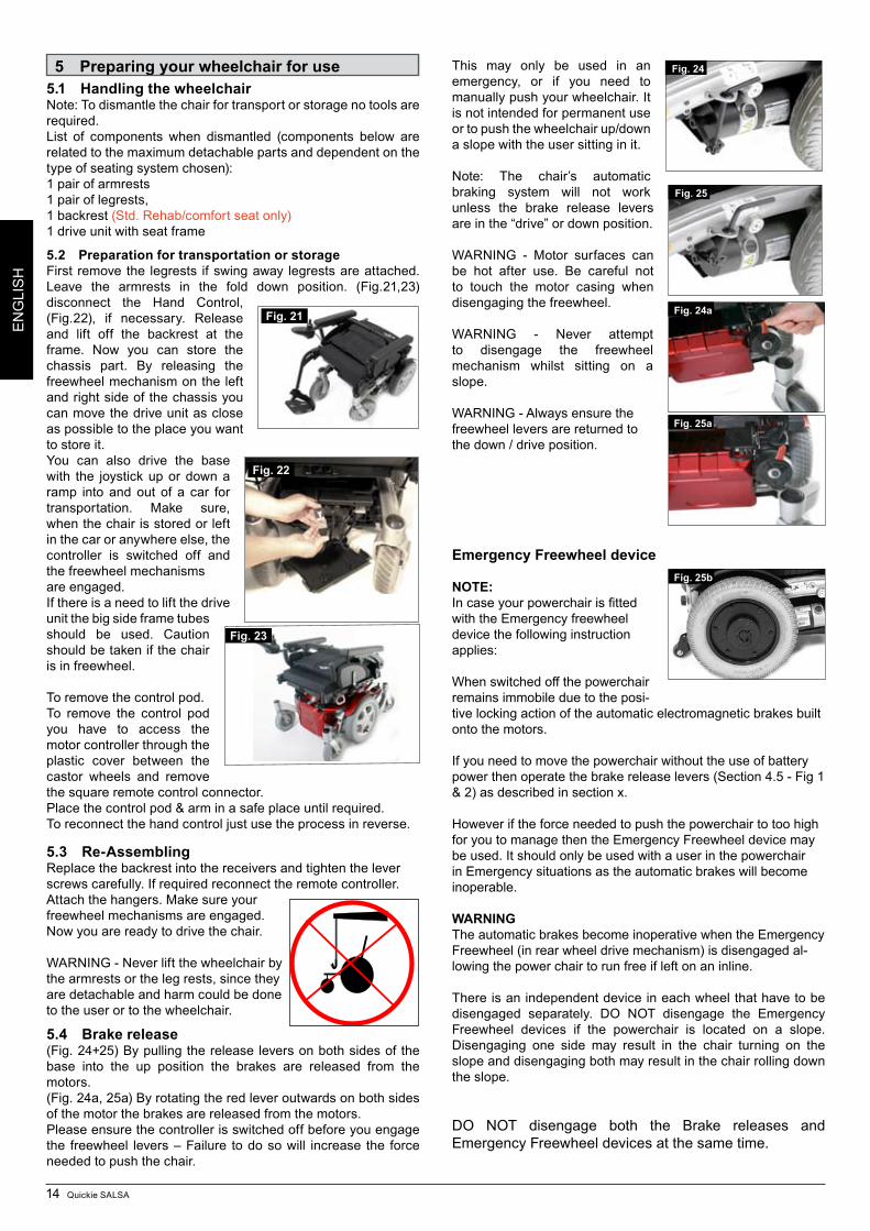
5.4 Brake release(Fig. 24+25) By pulling the release levers on both sides of the base into the up position the brakes are released from the motors. (Fig. 24a, 25a) By rotating the red lever outwards on both sides of the motor the brakes are released from the motors.Please ensure the controller is switched off before you engage the freewheel levers – Failure to do so will increase the force needed to push the chair.
This may only be used in an emergency, or if you need to manually push your wheelchair. It is not intended for permanent use or to push the wheelchair up/down a slope with the user sitting in it.
Note: The chair’s automatic braking system will not work unless the brake release levers are in the “drive” or down position.
WARNING - Motor surfaces can be hot after use. Be careful not to touch the motor casing when disengaging the freewheel.
WARNING - Never attempt to disengage the freewheel mechanism whilst sitting on a slope.
WARNING - Always ensure the freewheel levers are returned to the down / drive position.
Emergency Freewheel device
NOTE:Incaseyourpowerchairisfittedwith the Emergency freewheel device the following instruction applies:
When switched off the powerchair remains immobile due to the posi-tive locking action of the automatic electromagnetic brakes built onto the motors.
If you need to move the powerchair without the use of battery power then operate the brake release levers (Section 4.5 - Fig 1 & 2) as described in section x.
However if the force needed to push the powerchair to too high for you to manage then the Emergency Freewheel device may be used. It should only be used with a user in the powerchair in Emergency situations as the automatic brakes will become inoperable.
WARNINGThe automatic brakes become inoperative when the Emergency Freewheel (in rear wheel drive mechanism) is disengaged al-lowing the power chair to run free if left on an inline.
There is an independent device in each wheel that have to be disengaged separately. DO NOT disengage the Emergency Freewheel devices if the powerchair is located on a slope. Disengaging one side may result in the chair turning on the slope and disengaging both may result in the chair rolling down the slope.
DO NOT disengage both the Brake releases and Emergency Freewheel devices at the same time.
Fig. 24
Fig. 25
Fig. 21
Fig. 22
Fig. 23
Fig. 25a
Fig. 24a
Fig. 25b
EASY 160, 160 HP 15
DE
UTS
CH
DO NOT switch on and operate the powerchair control system whilst the Emergency freewheel is disengaged.Always re-engage the drive mechanism on the rear wheels when the chair is not being pushed.
To Disengage the Emergency freewheel pull out and push over the operating cam lever – see Fig A.
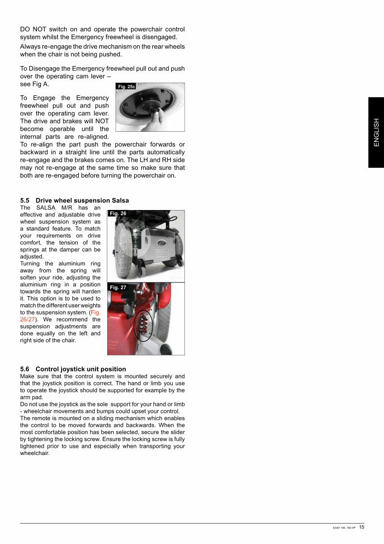
To Engage the Emergency freewheel pull out and push over the operating cam lever. The drive and brakes will NOT become operable until the internal parts are re-aligned. To re-align the part push the powerchair forwards or backward in a straight line until the parts automatically re-engage and the brakes comes on. The LH and RH side may not re-engage at the same time so make sure that both are re-engaged before turning the powerchair on.
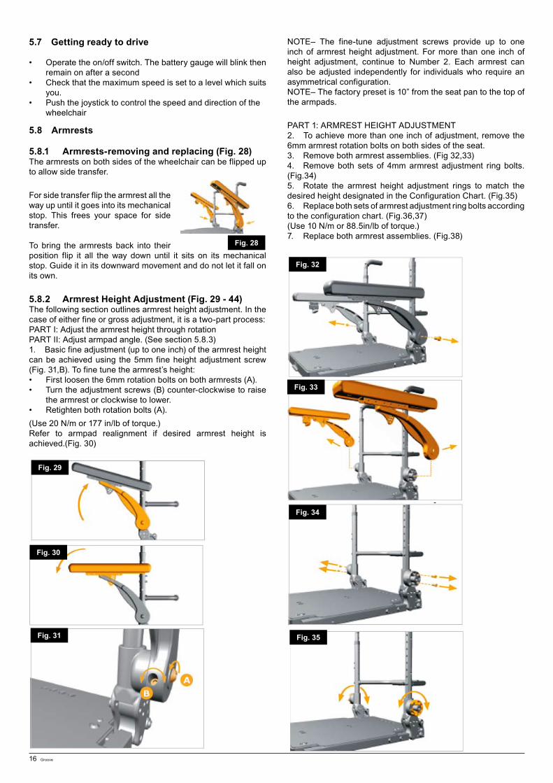
5.5 Drive wheel suspension SalsaThe SALSA M/R has an effective and adjustable drive wheel suspension system as a standard feature. To match your requirements on drive comfort, the tension of the springs at the damper can be adjusted.Turning the aluminium ring away from the spring will soften your ride, adjusting the aluminium ring in a position towards the spring will harden it. This option is to be used to match the different user weights to the suspension system. (Fig. 26/27). We recommend the suspension adjustments are done equally on the left and right side of the chair.
5.6 Control joystick unit positionMake sure that the control system is mounted securely and that the joystick position is correct. The hand or limb you use to operate the joystick should be supported for example by the arm pad. Do not use the joystick as the sole support for your hand or limb - wheelchair movements and bumps could upset your control.The remote is mounted on a sliding mechanism which enables the control to be moved forwards and backwards. When the most comfortable position has been selected, secure the slider by tightening the locking screw. Ensure the locking screw is fully tightened prior to use and especially when transporting your wheelchair.
Fig. 26
Fig. 27
EN
GLI
SH
Fig. 25c
16 Groove
5.7 Getting ready to drive
• Operatetheon/offswitch.Thebatterygaugewillblinkthenremain on after a second
• Checkthatthemaximumspeedissettoalevelwhichsuitsyou.
• Pushthejoysticktocontrolthespeedanddirectionofthewheelchair
5.8 Armrests
5.8.1 Armrests-removing and replacing (Fig. 28) The armrests on both sides of the wheelchair can be flipped up to allow side transfer.
For side transfer flip the armrest all the way up until it goes into its mechanical stop. This frees your space for side transfer.
To bring the armrests back into their position flip it all the way down until it sits on its mechanical stop. Guide it in its downward movement and do not let it fall on its own.
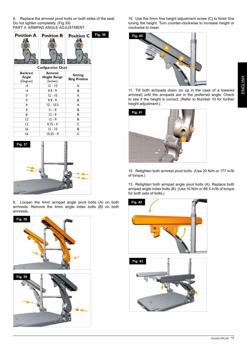
5.8.2 Armrest Height Adjustment (Fig. 29 - 44)The following section outlines armrest height adjustment. In the case of either fine or gross adjustment, it is a two-part process:PART I: Adjust the armrest height through rotationPART II: Adjust armpad angle. (See section 5.8.3)1. Basic fine adjustment (up to one inch) of the armrest height can be achieved using the 5mm fine height adjustment screw (Fig. 31,B). To fine tune the armrest’s height:• Firstloosenthe6mmrotationboltsonbotharmrests(A).• Turntheadjustmentscrews(B)counter-clockwisetoraise
the armrest or clockwise to lower.• Retightenbothrotationbolts(A).(Use 20 N/m or 177 in/lb of torque.)Refer to armpad realignment if desired armrest height is achieved.(Fig. 30)
NOTE– The fine-tune adjustment screws provide up to one inch of armrest height adjustment. For more than one inch of height adjustment, continue to Number 2. Each armrest can also be adjusted independently for individuals who require an asymmetrical configuration. NOTE– The factory preset is 10” from the seat pan to the top of the armpads.
PART 1: ARMREST HEIGHT ADJUSTMENT2. To achieve more than one inch of adjustment, remove the 6mm armrest rotation bolts on both sides of the seat.3. Remove both armrest assemblies. (Fig 32,33)4. Remove both sets of 4mm armrest adjustment ring bolts.(Fig.34)5. Rotate the armrest height adjustment rings to match the desired height designated in the Configuration Chart. (Fig.35)6. Replace both sets of armrest adjustment ring bolts according to the configuration chart. (Fig.36,37)(Use 10 N/m or 88.5in/lb of torque.)7. Replace both armrest assemblies. (Fig.38)
Fig. 28
Fig. 29
Fig. 30
Fig. 31
Fig. 32
Fig. 33
Fig. 34
Fig. 35
Quickie SALSA 17
EN
GLI
SH
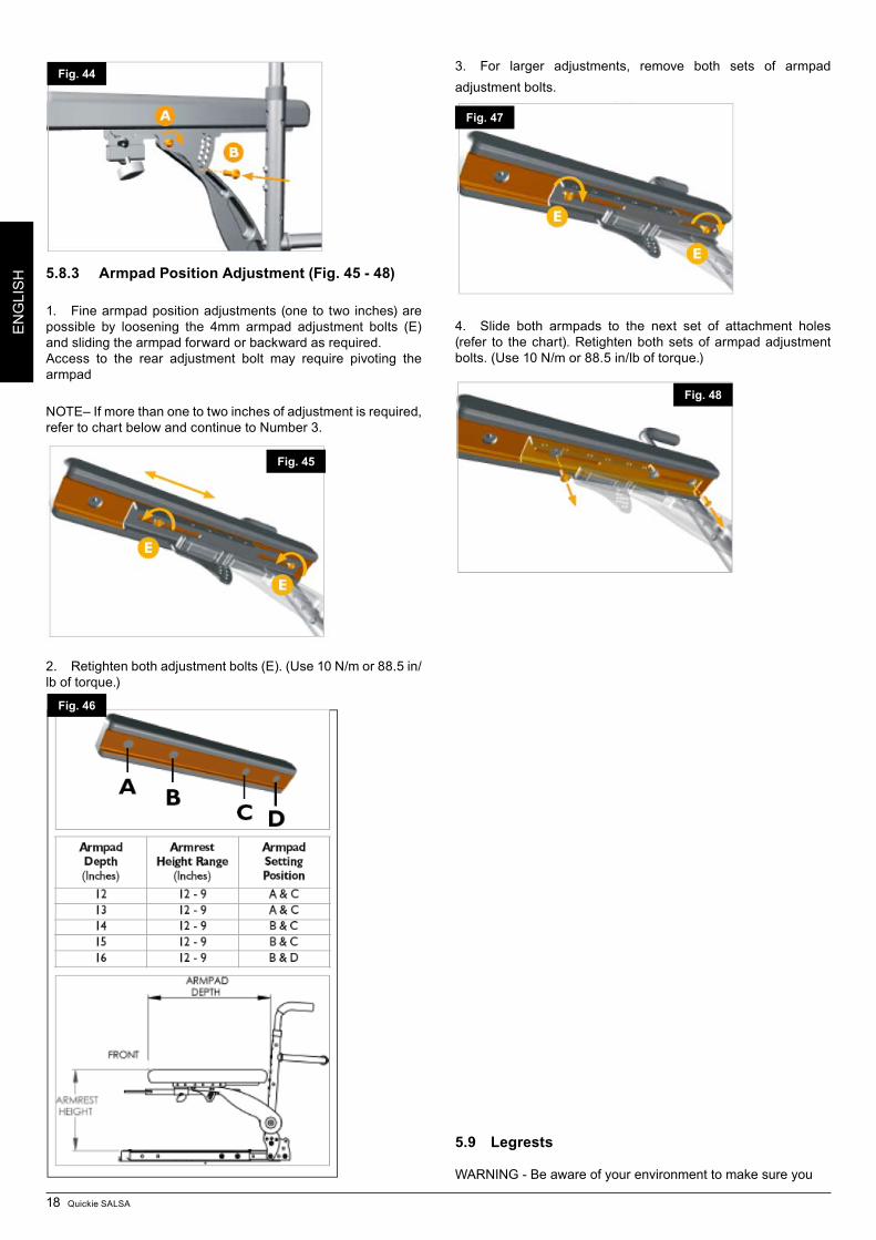
8. Replace the armrest pivot bolts on both sides of the seat.Do not tighten completely. (Fig.39)PART II: ARMPAD ANGLE ADJUSTMENT
9. Loosen the 4mm armpad angle pivot bolts (A) on both armrests. Remove the 4mm angle index bolts (B) on both armrests.
10. Use the 5mm fine height adjustment screw (C) to finish fine tuning the height. Turn counter-clockwise to increase height or clockwise to lower.
11. Tilt both armpads down (or up in the case of a lowered armrest) until the armpads are in the preferred angle. Check to see if the height is correct. (Refer to Number 10 for further height adjustment.)
12. Retighten both armrest pivot bolts. (Use 20 N/m or 177 in/lb of torque.)
13. Retighten both armpad angle pivot bolts (A). Replace both armpad angle index bolts (B). (Use 10 N/m or 88.5 in/lb of torque for both sets of bolts.)
Fig. 36
Fig. 37
Fig. 38
Fig. 39
Fig. 40
Fig. 41
Fig. 42
Fig. 43
18 Quickie SALSA
EN
GLI
SH 5.8.3 Armpad Position Adjustment (Fig. 45 - 48)
1. Fine armpad position adjustments (one to two inches) are possible by loosening the 4mm armpad adjustment bolts (E) and sliding the armpad forward or backward as required.Access to the rear adjustment bolt may require pivoting the armpad
NOTE– If more than one to two inches of adjustment is required, refer to chart below and continue to Number 3.
2. Retighten both adjustment bolts (E). (Use 10 N/m or 88.5 in/lb of torque.)
3. For larger adjustments, remove both sets of armpad adjustment bolts.
4. Slide both armpads to the next set of attachment holes (refer to the chart). Retighten both sets of armpad adjustment bolts. (Use 10 N/m or 88.5 in/lb of torque.)
5.9 Legrests
WARNING - Be aware of your environment to make sure you
Fig. 44
Fig. 45
Fig. 46
Fig. 47
Fig. 48
Quickie SALSA 19
EN
GLI
SH
do not injure your legs when legrests are extended.
WARNING - Always ensure that the legrests or footplates do not come into contact with the castors before driving the wheelchair.
WARNING - Legrests are not to be used for lifting or carrying the wheelchair with an occupant.
5.9.1 Fitting legrestOffer the legrest assembly at right angles to the frame (Fig. 51), locate the stem into the legrest and swing the assembly forward
to lock in position. To swing away the footrest, depress the retaining catch and turn the footrest out. This can now be lifted out if required, (Fig. 50).
5.9.2
FootplatesThe footplates may be flipped up to aid entry and exit from the chair.
WARNING - Do not use the footplates to stand on as the full weight of your body may cause the chair to tip forwards. This could result in injury and could damage the footrests.
5.9.3 Adjusting the footrest lengthTo adjust the footrest length remove the screw assembly on the footrest stem as shown in (Fig. 52), adjust the length to suit. Ensure the bolts are firmly located and tighten ed prior to use.
Note: The internal footrest stem may require cutting down in length to allow the footplate position to be raised.
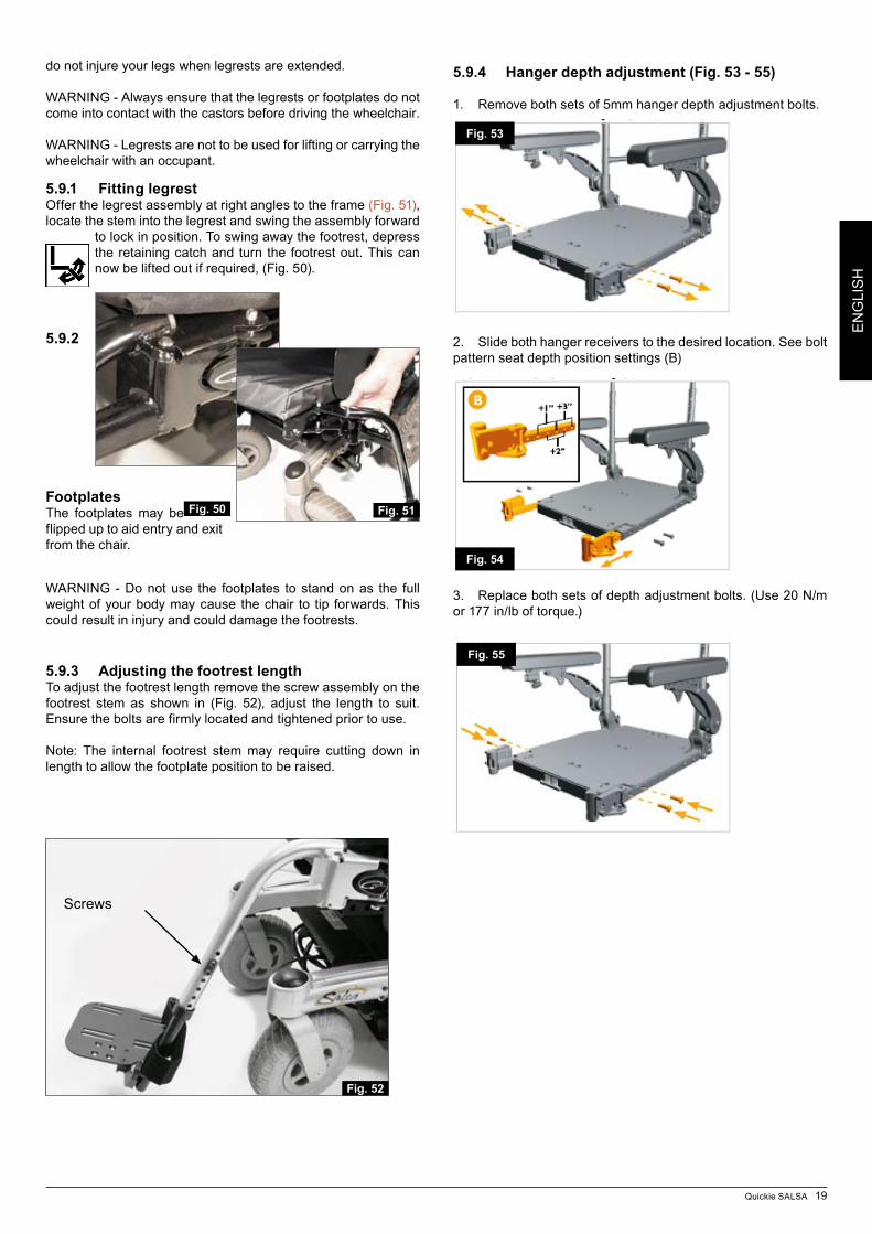
5.9.4 Hanger depth adjustment (Fig. 53 - 55)
1. Remove both sets of 5mm hanger depth adjustment bolts.
2. Slide both hanger receivers to the desired location. See bolt pattern seat depth position settings (B)
3. Replace both sets of depth adjustment bolts. (Use 20 N/m or 177 in/lb of torque.)
Fig. 50 Fig. 51
Screws
Fig. 52
Fig. 53
Fig. 54
Fig. 55
20 Quickie SALSA
EN
GLI
SH
5.9.5 Manual Articulating / Elevating Legrest (ALR/ELR)
To elevate:Pull the legrest upwards and stop at the desired height. The legrest will automatically lock in the chosen position.
To lower:Push the release lever slowly forward. The legrest will lower the angle. As soon as you release the lever, the legrest will be locked in the current position.
WARNING - Keep hands clear of the adjustment mechanism between the frame and the movable parts of the legrest while elevating or lowering the legrest.
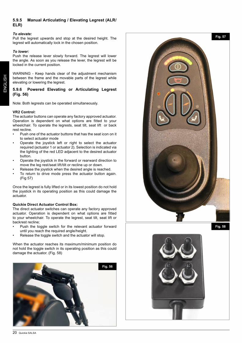
5.9.6 Powered Elevating or Articulating Legrest (Fig. 56)
Note: Both legrests can be operated simultaneously.
VR2 Control:The actuator buttons can operate any factory approved actuator. Operation is dependent on what options are fitted to your wheelchair. To operate the legrests, seat tilt, seat lift or back rest recline. • Pushoneoftheactuatorbuttonsthathastheseaticononit
to select actuator mode• Operate the joystick left or right to select the actuator
required (actuator 1 or actuator 2). Selection is indicated via the lighting of the red LED adjacent to the desired actuator button.
• Operatethejoystickintheforwardorrearwarddirectiontomove the leg rest/seat lift/tilt or recline up or down.
• Releasethejoystickwhenthedesiredangleisreached.• To return to drivemode press the actuator button again.
(Fig 57)
Once the legrest is fully lifted or in its lowest position do not hold the joystick in its operat ing position as this could damage the actuator.
Quickie Direct Actuator Control Box:The direct actuator switches can operate any factory approved actuator. Operation is dependent on what options are fitted to your wheelchair. To operate the legrest, seat tilt, seat lift or backrest recline; • Push the toggle switch for the relevant actuator forward
until you reach the required angle/height. • Releasethetoggleswitchandtheactuatorwillstop.
When the actuator reaches its maximum/minimum position do not hold the toggle switch in its operating position as this could damage the actuator. (Fig. 58)
Fig. 57
Fig. 58
Fig. 56
Quickie SALSA 21
EN
GLI
SH
6 Seating
6.1 Firm seat boardThe firm seat board is designed to allow pressure relief cushions such as Jay to be used.
6.2 Seat cushionsSeat cushions supplied by Sunrise Medical will have Velcro® strips that correspond to patches on the seat. You must ensure these are aligned prior to using the wheelchair. Other cushions used should also have Velcro® strips in a similar position to ensure the cushion does not slip off the seat. The seat cushions, supplied by Sunrise Medical all have removable covers.
6.3 Removable seat coversThe seat covers are all fully removable using zips or Velcro®. Once brackets are removed seat covers can be removed. The zip for the backrest is located on the under side of the cushion.
6.4 Standard backrest upholsterySalsa is supplied with optima backrest upholstery, which can be adjusted in tension to the individual’s requirements.
Tension adjustable back:To change the shape and/or tension of the ‘Optima’ backrest, remove the padded cover from the rear of the backrest and expose the tension straps. Loosen or tighten the straps to suit. (The most comfortable and supportive position is achieved with the wheelchair user seated in the chair). Ensure the straps are securely fastened and replace the padded cover prior to use.
6.5 JAY backrestsThe standard backrest assembly will allow the fitting of a JAY backrest, which is available as an optional extra.
6.6 Seat height adjustmentTo change the seat height loosen the two bolts and remove the front posts of the seat module Interface (Fig. 59 & 60) on the bottom frame with a 5mm allen key. The bolts can be accessed through taking off the front control module cover.
Salsa R only:Take the safety clips off the flat rear pins and pull the bolts out. Loosen the two clamping bolts at the rear flat posts.
Make sure the top frame does not trap your fingers. Hold the top frame securely in the up position. Adjust the seat height by choosing your required hole position of the Module Interface and replace the bolts and the pins. Tighten them securely and make sure that the safety clips are refitted
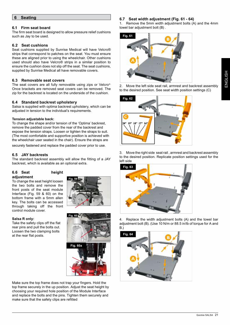
6.7 Seat width adjustment (Fig. 61 - 64)1. Remove the 5mm width adjustment bolts (A) and the 4mm towel bar adjustment bolt (B) .
2. Move the left side seat rail, armrest and backrest assembly to the desired position. See seat width position settings (C)
3. Move the right side seat rail , armrest and backrest assembly to the desired position. Replicate position settings used for the left side
4. Replace the width adjustment bolts (A) and the towel bar adjustment bolt (B). (Use 10 N/m or 88.5 in/lb of torque for A and B.)
Fig. 59
Fig. 60
Fig. 61
Fig. 62
Fig. 63
Fig. 64
Fig. 60a
22 Quickie SALSA
EN
GLI
SH
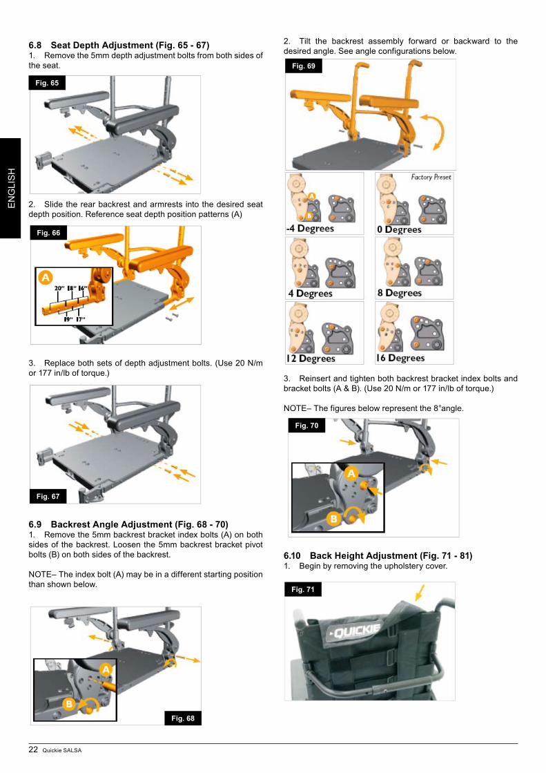
6.8 Seat Depth Adjustment (Fig. 65 - 67)1. Remove the 5mm depth adjustment bolts from both sides of the seat.
2. Slide the rear backrest and armrests into the desired seat depth position. Reference seat depth position patterns (A)
3. Replace both sets of depth adjustment bolts. (Use 20 N/m or 177 in/lb of torque.)
6.9 Backrest Angle Adjustment (Fig. 68 - 70)1. Remove the 5mm backrest bracket index bolts (A) on both sides of the backrest. Loosen the 5mm backrest bracket pivot bolts (B) on both sides of the backrest.
NOTE– The index bolt (A) may be in a different starting position than shown below.
2. Tilt the backrest assembly forward or backward to the desired angle. See angle configurations below.
3. Reinsert and tighten both backrest bracket index bolts and bracket bolts (A & B). (Use 20 N/m or 177 in/lb of torque.)
NOTE– The figures below represent the 8°angle.
6.10 Back Height Adjustment (Fig. 71 - 81)1. Begin by removing the upholstery cover.
Fig. 65
Fig. 66
Fig. 67
Fig. 68
Fig. 69
Fig. 70
Fig. 71
Quickie SALSA 23
EN
GLI
SH
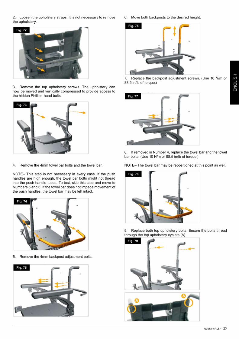
2. Loosen the upholstery straps. It is not necessary to remove the upholstery.
3. Remove the top upholstery screws. The upholstery can now be moved and vertically compressed to provide access to the hidden Phillips-head bolts.
4. Remove the 4mm towel bar bolts and the towel bar.
NOTE– This step is not necessary in every case. If the push handles are high enough, the towel bar bolts might not thread into the push handle tubes. To test, skip this step and move to Numbers 5 and 6. If the towel bar does not impede movement of the push handles, the towel bar may be left intact.
5. Remove the 4mm backpost adjustment bolts.
6. Move both backposts to the desired height.
7. Replace the backpost adjustment screws. (Use 10 N/m or 88.5 in/lb of torque.)
8. If removed in Number 4, replace the towel bar and the towel bar bolts. (Use 10 N/m or 88.5 in/lb of torque.)
NOTE– The towel bar may be repositioned at this point as well.
9. Replace both top upholstery bolts. Ensure the bolts thread through the top upholstery eyelets (A).
Fig. 72
Fig. 73
Fig. 74
Fig. 75
Fig. 76
Fig. 77
Fig. 78
Fig. 79
24 Quickie SALSA
EN
GLI
SH
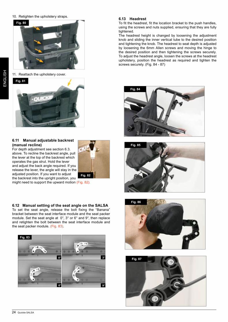
10. Retighten the upholstery straps.
11. Reattach the upholstery cover.
6.11 Manual adjustable backrest (manual recline)For depth adjustment see section 6.3. above. To recline the backrest angle, pull the lever at the top of the backrest which operates the gas strut. Hold the lever and adjust the back angle required. If you release the lever, the angle will stay in the adjusted position. If you want to adjust the backrest into the upright position, you might need to support the upward motion (Fig. 82).
6.12 Manual setting of the seat angle on the SALSATo set the seat angle, release the bolt fixing the “Banana” bracket between the seat interface module and the seat packer module. Set the seat angle at 0°, 3° or 6° and 9°, then replace and re tighten the bolt between the seat interface module and the seat packer module. (Fig. 83).
6.13 HeadrestTo fit the headrest, fit the location bracket to the push handles, using the screws and nuts supplied, ensuring that they are fully tightened.The headrest height is changed by loosening the adjustment knob and sliding the inner vertical tube to the desired position and tightening the knob. The headrest to seat depth is adjusted by loosening the 6mm Allen screws and moving the hinge to the desired position and then tightening the screws securely. To adjust the headrest angle, loosen the screws at the headrest upholstery, position the headrest as required and tighten the screws securely. (Fig. 84 - 87)
Fig. 83
6° 9°
0° 3°
Fig. 84
Fig. 85
Fig. 86
Fig. 87
Fig. 80
Fig. 81
Fig. 82
Quickie SALSA 25
EN
GLI
SH
6.14 Powered Seating
WARNING -
• Itispossibletoreversethedirectionofanactuatorrelativeto the direction of the joystick. Ensure you know which direction to move the joystick for the desired operation. Failure to do so may result in damage and/or injury.
Please refer to Section 7 for details of your hand control
Powered adjustable backrest:
WARNING - Lowering the backrest by an angle of greater than 15° from vertical alters the balance of your wheelchair. Never exceed 15° of recline when on any
gradient or when driving your wheelchair.
VR2 Control
To recline the backrest angle:• Pushthemodebuttontoselectactuatormode• Operate the joystick left or right to select the actuator
required (actuator 1 or actuator 2). Selection is indicated via the lighting of the orange LED adjacent to the desired actuator number.
• Operatethejoystickintheforwardorrearwarddirectiontomove the backrest up or down.
• Releasethejoystickwhenthedesiredangleisreached.• Toreturntodrivemode,presstheactuatorbuttonagain.
Once the back is fully reclined or raised do not hold the joystick in its operating position as this could damage the actuator.
Quickie Direct Actuator Control Box (Fig. 58 & 88)
To recline the backrest angle: • Pushtherelevanttoggleswitchintotheforwardposition.• Release the toggle switch when the desired angle is
reached.
Once the back is fully reclined or raised do not hold the switch in its operating position as this could damage the actuator.
Powered seat lift:The seat can lift up to 30 cm by operating it through your control system.
WARNING - Operating the powered lift from its lowest position will bring the chair into ”creep mode“, moving it below will allow full speed.
Quickie VR2 Control:
To operate the powered lift:• Push the mode button to select actuator
mode• Operate the joystick left or right to select the actuator
required (actuator 1 or actuator 2). Selection is indicated via the lighting of the orange LED adjacent to the desir ed actuator number.
• Operatethejoystickintheforwardorrearwarddirectiontomove the lift up or down.
• Releasethejoystickwhenthedesiredangleisreached.• Toreturntodrivemode,presstheactuatorbuttonagain.
Once the lift is fully raised or in its lowest position do not hold
the joystick in its operating position as this could damage the actuator.
Quickie Direct Actuator Control Box (Fig. 58 & 88)
To lift the seat:• Operate the relevant toggle switch in the forward or
rearward direction to move the lift up or down. • Releasetheswitchwhenthedesiredheightisreached.
Once the lift is fully raised or in its lowest position do not hold the switch in its operating position as this could damage the actuator.
Powered seat tilt:The seat can tilt up to 30° by operating it through your control system.WARNING - Operating the powered tilt greater than 9° from its lowest position will bring the chair into ”creep
mode“. If this operation occurs simultaneously with the seat lifted the chair will be inhibited and will not drive.
Quickie VR2 Control
To operate the powered tilt:• Pushthemodebuttontoselectactuatormode• Operate the joystick left or right to select the actuator
required (actuator 1 or actuator 2). Selection is indicated via the lighting of the orange LED adjacent to the desired actuator number.
• Operatethejoystickintheforwardorrearwarddirectiontomove the tilt forward or backward.
• Releasethejoystickwhenthedesiredangleisreached.• Toreturntodrivemode,presstheactuatorbuttonagain.
Once the seat is fully tilted or in its lowest position do not hold the joystick in its operat ing position as this could damage the actuator.
Quickie Direct Actuator Control Box (Fig. 88)To tilt the seat:• Operate the relevant toggle switch in the forward or
rearward direction to move the Tilt up or down. • Releasetheswitchwhenthedesiredangleisreached.
Once the seat is fully tilted or in the lowest position do not hold the switch in its operating position as this could damage the actuator.
Fig. 88
26 Quickie SALSA
EN
GLI
SH
7.0 The VR2 Hand Control Series
7.1 VR2
On/off button:The on/off button applies power to the control system electronics, which in turn supply power to the wheelchairs motors. Do not use the on/off button to stop the wheelchair unless there is an emergency. (If you do you may shorten the life of the wheelchair drive components)
Battery gauge:The battery gauge shows you that the wheelchair is switched on. It also indicates the status of the wheelchair. Refer to chapter 8.
Locking/unlocking the wheelchair:The VR2 control system can be locked to prevent unauthorised use. The locking method is via a sequence of key presses and joystick movements as detailed below.
To lock the wheelchair• Whilethecontrolsystemisswitchedon,depressandhold
the on/off button• After1second thecontrolsystemwillbeep.Nowrelease
the on/off button• Deflectthejoystickforwardsuntilthecontrolsystembeeps• Deflect the joystick in reverse until the control system
beeps• Releasethejoystick,therewillbealongbeep• Thewheelchairisnowlocked
To unlock the wheelchair• Usetheon/offbuttontoswitchthecontrolsystemon.The
maximum speed/profile indicator will be rippling up and down
• Deflectthejoystickforwardsuntilthecontrolsystembeeps• Deflect the joystick in reverse until the control system
beeps• Releasethejoystick,therewillbealongbeep• ThewheelchairisnowunlockedOperating the control joystick:When engaging the main On/Off button, allow a few seconds prior to moving the joystick. This allows the system to self check. If you move the joystick too soon, the battery level indicator display will not illuminate until the joystick is released.If it is off null for more than 5 seconds a system error will occur.Whilst this is not harmful to your wheelchair, you will need to switch off and then back on to clear the system.Note: This is a safety feature to prevent unintended movement.
Proportional control summary1. To steer, move the joystick in the direction you wish to go.2. The further you move the joystick, the faster you will go.3. New users should use slower speeds until they feel
confident when driving the wheelchair. 4. The brakes will automatically stop the wheelchair from any
speed when the joystick is released.5. It is important that the chair is stationary when changing
direction from reverse to forward.6. Always switch off before getting into or out of the chair.
Maximumspeed/profileindicator:This is a gauge which shows the maximum speed setting for the wheelchair or if the control system is programmed for drive profile operation, the selected drive profile. This gauge also indicates if the speed of the wheelchair is being limited or if the control system is locked.
The horn button:The horn will sound while this button is depressed.
Speed/Profiledecreasebutton:This button decreases the maximum speed setting or, if the control system is programmed for drive profile operation, selects a lower drive profile.
Speed/Profileincreasebutton:This button increases the maximum speed setting or, if the control system is programmed for drive profile operation, selects a higher drive profile.
Actuator button and LEDs:Depending on whether your wheelchair is fitted with one or two actuators the operation of these buttons will differ.
Wheelchairs with one actuatorDepressing either actuator button will enter actuator adjustment mode. This will be indicated by the illumination of both actuator LED’s. Actuator adjustment can then be made by deflecting the joystick forwards or backwards. To re enter drive mode, depress either actuator button
Wheelchairs with two actuatorsDepressing either actuator button will enter actuator adjustment mode. If the left button is depressed the associated LED will be illuminated, and deflection of the joystick will adjust the actuator motor connected to that channel. If the right button is depressed the associated LED will be illuminated, and deflection of the joystick will adjust the actuator motor connected to the other channel. To re enter drive mode, depress the selected actuator button, as indicated by the associated LEDIt is also possible to select the other actuator by left or right movements of the joystick
Charging and programming socket:This socket should only be used for programming and charging the wheelchair. This socket should not be used as a power supply for any other device. Connection of other electrical devices may damage the control system or affect the EMC performance of the wheelchairSee section 11 about charging.
The programming socket will enable an approved Sunrise Medical authorised dealer to re-programme your chair and also gain useful information when tracing any faults. When the chair leaves the factory, the parameters of the controller are set to default.To programme the controller you need a special programming device (handheld or PC software), which is available through your Sunrise Medical authorised dealer.
WARNING - Programming the controller of the wheelchair is only allowed through authorised personnel trained by Sunrise Medical. Incorrect controller settings could cause driving outside the safe limits and could result in damage or injury.
Note: SUNRISE MEDICAL does not accept responsibility for damages which result from unexpected stopping of the wheelchair or inappropriate programming or unauthorised use of the wheelchair.
Quickie SALSA 27
EN
GLI
SH
7.2 VR2-LThere are common controls between the VR2 and the VR2-L control systems where a control differs it will be described below. All common controls can be found on the previous page.
Lights and indicators:The SALSA can be equipped with lights and indicators. Where lights are not factory fitted, they may be fitted as an optional extra by an approved Sunrise Medical authorised dealer.
WARNINGEnsure that the lights and indicators are functioning correctlyand lenses are clean before going outdoors at night.
Indicators:To turn on the wheelchairs indicators operate the required button either left or right, the associated LED will also illuminate continuously. If the LED flashes rapidly either a total short circuit, a single lamp open circuit or a total open circuit in the left or right indicator circuit has been detectedDepress the indicator button to turn off the indicator and the associated LED
Main lights:To turn on the wheelchairs lights operate this button, the associated LED will illuminate continuously. If the LED flashes a short circuit in the lighting circuit has been detectedDepress the light button to turn off the lights and the associated LED
Hazard warning lights:To turn on the wheelchairs hazard warning lights operate this button, the associated LED will flash at the same rate. The left and right turn indicator LEDs will also flash. If the LED flashes rapidly either a total short circuit, a single lamp open circuit or a total open circuit in the entire indicator circuit has been detectedDepress the hazard warning button to turn off the lights and the associated LED
Actuator button and LEDs:Depending on whether your wheelchair is fitted with one or two actuators the operation of this button will differ.
Wheelchairs with one actuatorDepressing the actuator button will enter actuator adjustment mode. This will be indicated by the illumination of both actuator LED’s. Actuator adjustment can then be made by deflecting the joystick forwards or backwards. To re enter drive mode, depress either actuator button
Wheelchairs with two actuatorsDepressing the actuator button will enter actuator adjustment mode. Depressing the button once illuminates the left LED, and deflection of the joystick will adjust the actuator motor connected to that channel. If the right button is depressed the associated LED will be illuminated, and deflection of the joystick will adjust the actuator motor connected to the other channel. To re enter drive mode, depress the selected actuator button, as indicated by the associated LEDIt is also possible to select the other actuator by left or right movements of the joystick
7.3 VR2 Dual control unit
Control button and indicator:This shows which joystick has control. If the red wheelchair light is on the wheelchair occupants joystick has control. If the green attendant light is on the dual attendant systems joystick has control. The button is used to transfer control between the two choices
Actuator button and LED:All VR2 dual attendant systems have an actuator button fitted as standard. If the VR2 is programmed with no actuators then this button has no function.
Wheelchairs with one actuatorDepressing the actuator button once will enter actuator adjustment mode. This will be indicated by the illumination of both actuator LED’s. Actuator adjustment can then be made by deflecting the joystick forwards and backwards.To re enter drive mode, depress either the actuator button or the speed button
Wheelchairs with two actuators:Depressing the actuator button will enter actuator adjustment mode. Depressing the button once illuminates the left LED and deflection of the joystick forwards or backwards will adjust the actuator connected to that channel. Selection between the two actuators is achieved by deflecting the joystick to the left and right. As the actuator selected changes so will the LED which illuminates. Left for actuator 1 and right for actuator 2To re enter drive mode, depress either the actuator buttonor the speed button
Maximum speed button and indicator:This shows the maximum speed setting for the wheelchair when the dual attendant system has control. There are five settings - setting 1 is the slowest speed and setting 5 is the highest speed. The speed setting is changed with the speed button.
If the control system is programmed for drive profile operation, then the dual attendant system speed adjuster will only adjust the speed within the selected profile.Changing between drive profiles can only be achieved using the VR2
28 Quickie SALSA
EN
GLI
SH
Charger & Programming Socket
Control Panel Joystick
Battery Gauge
On-Off Button
Horn Button
Max. Speed/Profile
Indication
Speed/Profile Decrease Button
Speed/Profile Increase Button
Hazards Button
Lights Button
Actuator Button
Indicator Buttons
VR2 Control Panel Layout VR2-L Control Panel Layout
Control ButtonActuator Button
Speed Indicator
Max. Speed Button
Control Panel
Joystick
VR2 Dual Control Unit
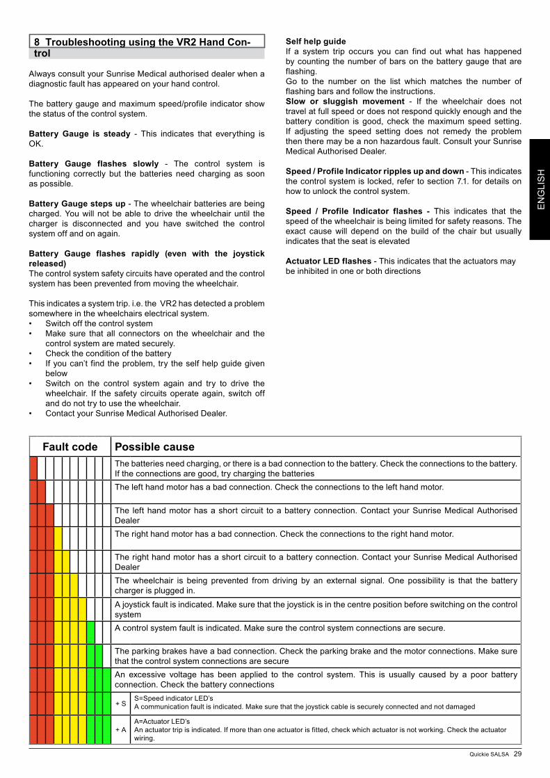
Quickie SALSA 29
EN
GLI
SH
Fault code Possible causeThe batteries need charging, or there is a bad connection to the battery. Check the connections to the battery. If the connections are good, try charging the batteriesThe left hand motor has a bad connection. Check the connections to the left hand motor.
The left hand motor has a short circuit to a battery connection. Contact your Sunrise Medical Authorised Dealer The right hand motor has a bad connection. Check the connections to the right hand motor.
The right hand motor has a short circuit to a battery connection. Contact your Sunrise Medical Authorised DealerThe wheelchair is being prevented from driving by an external signal. One possibility is that the battery charger is plugged in.
A joystick fault is indicated. Make sure that the joystick is in the centre position before switching on the control systemA control system fault is indicated. Make sure the control system connections are secure.
The parking brakes have a bad connection. Check the parking brake and the motor connections. Make sure that the control system connections are secureAn excessive voltage has been applied to the control system. This is usually caused by a poor battery connection. Check the battery connections
+ SS=Speed indicator LED’sA communication fault is indicated. Make sure that the joystick cable is securely connected and not damaged
+ AA=Actuator LED’sAn actuator trip is indicated. If more than one actuator is fitted, check which actuator is not working. Check the actuator wiring.
8 Troubleshooting using the VR2 Hand Con-trol
Always consult your Sunrise Medical authorised dealer when a diagnostic fault has appeared on your hand control.
The battery gauge and maximum speed/profile indicator show the status of the control system.
Battery Gauge is steady - This indicates that everything is OK.
Battery Gauge flashes slowly - The control system is functioning correctly but the batteries need charging as soon as possible.
Battery Gauge steps up - The wheelchair batteries are being charged. You will not be able to drive the wheelchair until the charger is disconnected and you have switched the control system off and on again.
Battery Gauge flashes rapidly (even with the joystick released)The control system safety circuits have operated and the control system has been prevented from moving the wheelchair.
This indicates a system trip. i.e. the VR2 has detected a problem somewhere in the wheelchairs electrical system.• Switchoffthecontrolsystem• Make sure that all connectors on thewheelchair and the
control system are mated securely.• Checktheconditionofthebattery• Ifyoucan’t findtheproblem,try theselfhelpguidegiven
below• Switch on the control system again and try to drive the
wheelchair. If the safety circuits operate again, switch off and do not try to use the wheelchair.
• ContactyourSunriseMedicalAuthorisedDealer.
Self help guideIf a system trip occurs you can find out what has happened by counting the number of bars on the battery gauge that are flashing.Go to the number on the list which matches the number of flashing bars and follow the instructions.Slow or sluggish movement - If the wheelchair does not travel at full speed or does not respond quickly enough and the battery condition is good, check the maximum speed setting. If adjusting the speed setting does not remedy the problem then there may be a non hazardous fault. Consult your Sunrise Medical Authorised Dealer.
Speed / Profile Indicator ripples up and down - This indicates the control system is locked, refer to section 7.1. for details on how to unlock the control system.
Speed / Profile Indicator flashes - This indicates that the speed of the wheelchair is being limited for safety reasons. The exact cause will depend on the build of the chair but usually indicates that the seat is elevated
Actuator LED flashes - This indicates that the actuators may be inhibited in one or both directions
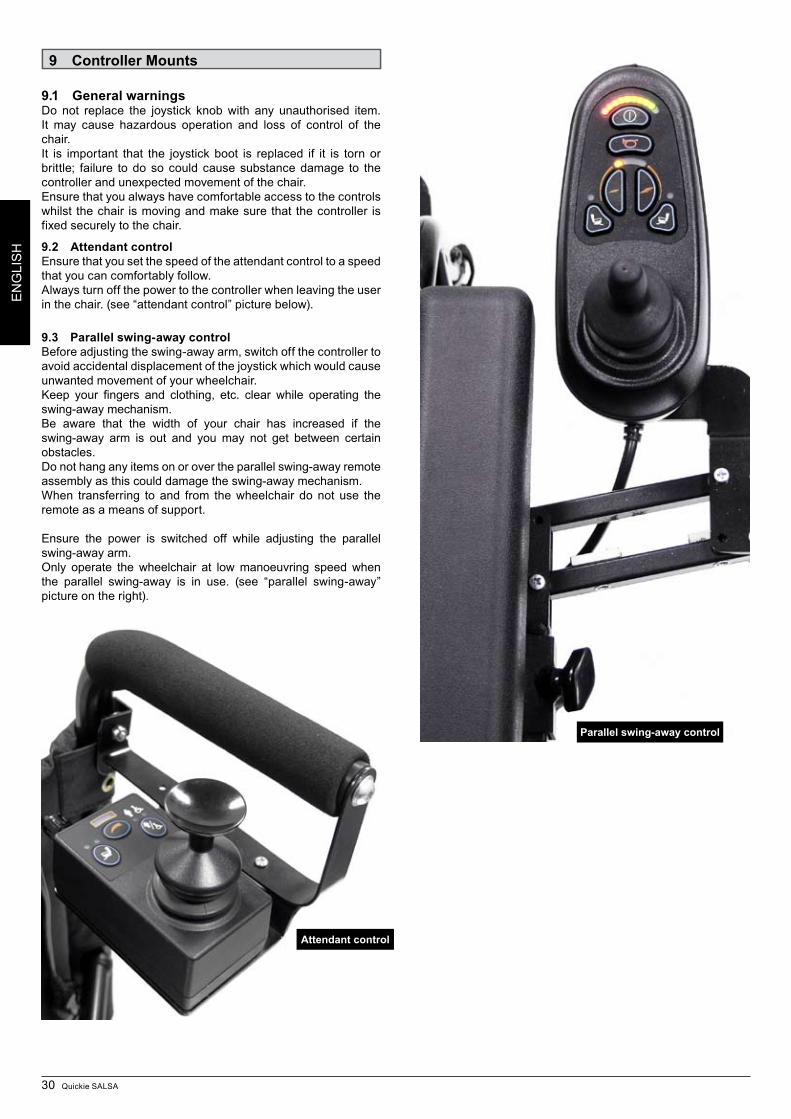
30 Quickie SALSA
EN
GLI
SH
9 Controller Mounts
9.1 General warningsDo not replace the joystick knob with any unauthorised item. It may cause hazardous operation and loss of control of the chair.It is important that the joystick boot is replaced if it is torn or brittle; failure to do so could cause substance damage to the controller and unexpected movement of the chair.Ensure that you always have comfortable access to the controls whilst the chair is moving and make sure that the controller is fixed securely to the chair.
9.2 Attendant controlEnsure that you set the speed of the attendant control to a speed that you can comfortably follow.Always turn off the power to the controller when leaving the user in the chair. (see “attendant control” picture below).
9.3 Parallel swing-away controlBefore adjusting the swing-away arm, switch off the controller to avoid accidental displacement of the joystick which would cause unwanted movement of your wheelchair.Keep your fingers and clothing, etc. clear while operating the swing-away mechanism.Be aware that the width of your chair has increased if the swing-away arm is out and you may not get between certain obstacles.Do not hang any items on or over the parallel swing-away remote assembly as this could damage the swing-away mechanism.When transferring to and from the wheelchair do not use the remote as a means of support.
Ensure the power is switched off while adjusting the parallel swing-away arm.Only operate the wheelchair at low manoeuvring speed when the parallel swing-away is in use. (see “parallel swing-away” picture on the right).
Attendant control
Parallel swing-away control
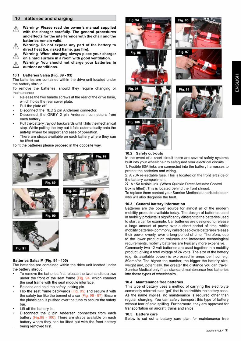
Quickie SALSA 31
EN
GLI
SH
10.2 Safety cut-outsIn the event of a short circuit there are several safety systems built into your wheelchair to safeguard your electrical circuits. 1. Fusible 80A links are connected into the battery harnesses to protect the batteries and wiring.2. A 70A re-settable fuse. This is located on the front left side of the battery compartment.3. A 15A fusible link. (When Quickie Direct Actuator Control Boxisfitted).Thisislocatedbehindthefrontshroud.To replace them contact your Sunrise Medical authorised dealer, who will also diagnose the fault.
10.3 General battery informationBatteries are the power source for almost all of the modern mobility products available today. The design of batteries used in mobility products is significantly different to the batteries used to start a car for example. Car batteries are designed to release a large amount of power over a short period of time, whilst mobility batteries (commonly called deep cycle batteries) release their power evenly, over a long period of time. Therefore, due to the lower production volumes and increased technological requirements, mobility batteries are typically more expensive.Commonly two 12 volt batteries are used together in a mobility product, giving a total voltage of 24 volts. The size of the battery (e.g. its available power) is expressed in amps per hour e.g. 80amp/hr. The higher the number, the bigger the battery size, weight and, potentially, the greater the distance you can travel. Sunrise Medical only fit as standard maintenance free batteries into these types of wheelchairs.
10.4 Maintenance free batteriesThis type of battery uses a method of carrying the electrolyte commonly referred to as ‘gel’, that is held within the battery case. As the name implies, no maintenance is required other than regular charging. You can safely transport this type of battery without fear of acid spilling. Furthermore, they are approved for transportation on aircraft, trains and ships.10.5 Battery careBelow is set out a battery care plan for maintenance free
10 Batteries and charging
Warning- Please read the owner’s manual supplied with the charger carefully. The general procedures and effects for the interference with the chair and the batteries remain valid.Warning- Do not expose any part of the battery to direct heat (i.e. naked flame, gas fire).Warning- When charging always place your charger on a hard surface in a room with good ventilation.Warning- You should not charge your batteries in outdoor conditions.
10.1 Batteries Salsa (Fig. 89 - 93)The batteries are contained within the drive unit located under the battery shroud. To remove the batteries, should they require changing or maintenance• Releasethetwohandlescrewsattherearofthedrivebase,
which holds the rear cover plate. • Pulltheplateoff.• DisconnecttheRED2pinAndersenconnector.• Disconnect the GREY 2 pin Andersen connectors from
each battery. Pull the battery tray out backwards until it hits the mechanical •stop. While pulling the tray out it falls automatically onto the anti-tip wheel for support and ease of operation.
• Therearestrapsavailableoneachbatterywheretheycanbe lifted out.
To fit the batteries please proceed in the opposite way.
Batteries Salsa M (Fig. 94 - 100)The batteries are contained within the drive unit located under the battery shroud.
To remove the batteries first release the two handle screws •under the front of the seat frame (Fig. 94, which connect the seat frame with the seat module interface. Release and hold the safety locking pin. •Flip the seat frame backwards • (Fig. 95) and secure it with the safety bar like the bonnet of a car (Fig. 96 - 97). Ensure the plastic cap is pushed over the tube to secure the safety bar. Lift off the battery lid. •Disconnect the 2 pin Andersen connectors from each •battery (Fig.98 - 100). There are straps available on each battery where they can be lifted out with the front battery being removed first.
Fig. 89
Fig. 92
Fig. 90
Fig. 91
Fig. 93
Fig. 94 Fig. 95
Fig. 96 Fig. 97
Fig. 98
Fig. 100
Fig. 99
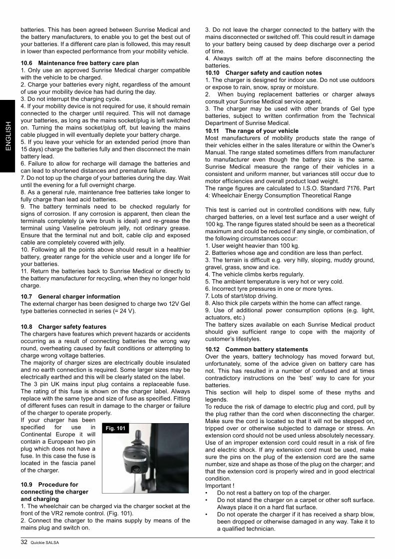
32 Quickie SALSA
EN
GLI
SH
batteries. This has been agreed between Sunrise Medical and the battery manufacturers, to enable you to get the best out of your batteries. If a different care plan is followed, this may result in lower than expected performance from your mobility vehicle.
10.6 Maintenance free battery care plan1. Only use an approved Sunrise Medical charger compatible with the vehicle to be charged.2. Charge your batteries every night, regardless of the amount of use your mobility device has had during the day.3. Do not interrupt the charging cycle.4. If your mobility device is not required for use, it should remain connected to the charger until required. This will not damage your batteries, as long as the mains socket/plug is left switched on. Turning the mains socket/plug off, but leaving the mains cable plugged in will eventually deplete your battery charge.5. If you leave your vehicle for an extended period (more than 15 days) charge the batteries fully and then disconnect the main battery lead.6. Failure to allow for recharge will damage the batteries and can lead to shortened distances and premature failure.7. Do not top up the charge of your batteries during the day. Wait until the evening for a full overnight charge.8. As a general rule, maintenance free batteries take longer to fully charge than lead acid batteries.9. The battery terminals need to be checked regularly for signs of corrosion. If any corrosion is apparent, then clean the terminals completely (a wire brush is ideal) and re-grease the terminal using Vaseline petroleum jelly, not ordinary grease. Ensure that the terminal nut and bolt, cable clip and exposed cable are completely covered with jelly.10. Following all the points above should result in a healthier battery, greater range for the vehicle user and a longer life for your batteries.11. Return the batteries back to Sunrise Medical or directly to the battery manufacturer for recycling, when they no longer hold charge.
10.7 General charger informationThe external charger has been designed to charge two 12V Gel type batteries connected in series (= 24 V).
10.8 Charger safety featuresThe chargers have features which prevent hazards or accidents occurring as a result of connecting batteries the wrong way round, overheating caused by fault conditions or attempting to charge wrong voltage batteries.The majority of charger sizes are electrically double insulated and no earth connection is required. Some larger sizes may be electrically earthed and this will be clearly stated on the label.The 3 pin UK mains input plug contains a replaceable fuse. The rating of this fuse is shown on the charger label. Always replace with the same type and size of fuse as specified. Fitting of different fuses can result in damage to the charger or failure of the charger to operate properly.If your charger has been specified for use in Continental Europe it will contain a European two pin plug which does not have a fuse. In this case the fuse is located in the fascia panel of the charger.
10.9 Procedure for connecting the charger and charging1. The wheelchair can be charged via the charger socket at the front of the VR2 remote control. (Fig. 101).2. Connect the charger to the mains supply by means of the mains plug and switch on.
3. Do not leave the charger connected to the battery with the mains disconnected or switch ed off. This could result in damage to your battery being caused by deep discharge over a period of time.4. Always switch off at the mains before disconnecting the batteries.10.10 Charger safety and caution notes1. The charger is designed for indoor use. Do not use outdoors or expose to rain, snow, spray or moisture.2. When buying replacement batteries or charger always consult your Sunrise Medical service agent.3. The charger may be used with other brands of Gel type batteries, subject to written confirmation from the Technical Department of Sunrise Medical. 10.11 The range of your vehicleMost manufacturers of mobility products state the range of their vehicles either in the sales literature or within the Owner’s Manual. The range stated sometimes differs from manufacturer to manufacturer even though the battery size is the same. Sunrise Medical measure the range of their vehicles in a consistent and uniform manner, but variances still occur due to motor efficiencies and overall product load weight.The range figures are calculated to I.S.O. Standard 7176. Part 4: Wheelchair Energy Consumption Theoretical Range
This test is carried out in controlled conditions with new, fully charg ed batteries, on a level test surface and a user weight of 100 kg. The range figures stated should be seen as a theoretical maximum and could be reduced if any single, or combination, of the following circumstances occur:1. User weight heavier than 100 kg.2. Batteries whose age and condition are less than perfect.3. The terrain is difficult e.g. very hilly, sloping, muddy ground, gravel, grass, snow and ice.4. The vehicle climbs kerbs regularly.5. The ambient temperature is very hot or very cold.6. Incorrect tyre pressures in one or more tyres.7. Lots of start/stop driving.8. Also thick pile carpets within the home can affect range.9. Use of additional power consumption options (e.g. light, actuators, etc.)The battery sizes available on each Sunrise Medical product should give sufficient range to cope with the majority of customer’s lifestyles.
10.12 Common battery statementsOver the years, battery technology has moved forward but, unfortunately, some of the advice given on battery care has not. This has resulted in a number of confused and at times contradictory instructions on the ‘best’ way to care for your batteries.This section will help to dispel some of these myths and legends.To reduce the risk of damage to electric plug and cord, pull by the plug rather than the cord when disconnecting the charger. Make sure the cord is located so that it will not be stepped on, tripped over or otherwise subjected to damage or stress. An extension cord should not be used unless absolutely necessary. Use of an improper extension cord could result in a risk of fire and electric shock. If any extension cord must be used, make sure the pins on the plug of the extension cord are the same number, size and shape as those of the plug on the charger; and that the extension cord is properly wired and in good electrical condition.Important !• Donotrestabatteryontopofthecharger.• Donotstandthechargeronacarpetorothersoftsurface.
Always place it on a hard flat surface.• Donotoperatethechargerifithasreceivedasharpblow,
been dropped or otherwise damaged in any way. Take it to a qualified technician.
Fig. 101
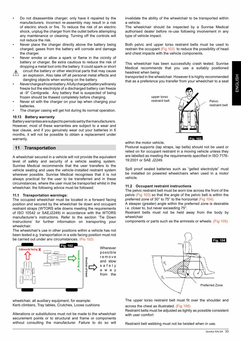
Quickie SALSA 33
EN
GLI
SH
• Donotdisassemblecharger;onlyhave it repairedby themanufacturers. Incorrect re-assembly may result in a risk of electric shock or fire. To reduce the risk of an electric shock, unplug the charger from the outlet before attempting any maintenance or cleaning. Turning off the controls will not reduce the risk.
• Never place the charger directly above the battery beingcharg ed; gases from the battery will corrode and damage the charger.
• Never smoke or allow a spark or flame in the vicinity ofbattery or charger. Be extra cautious to reduce the risk of dropping a metal tool onto the battery. It could spark or short
circuit the battery or other electrical parts that may cause an explosion. Also take off all personal metal effects and dangling objects when working on the battery.
• Neverchargeafrozenbattery.Afullychargedbatterywillrarelyfreeze but the electrolyte of a discharged battery can freeze at -9° Centigrade. Any battery that is suspected of being frozen should be thawed completely before charging.
• Neversitwiththechargeronyourlapwhenchargingyourbatteries.
• Thechargercasingwillgethotduringitsnormaloperation.
10.13 Battery warrantyBattery warranties are subject to periods set by the manufacturers. However, most of these warranties are subject to a wear and tear clause, and if you genuinely wear out your batteries in 6 months, it will not be possible to obtain a replacement under warranty.
11 Transportation
A wheelchair secured in a vehicle will not provide the equivalent level of safety and security of a vehicle seating system. Sunrise Medical recommends that the user transfers to the vehicle seating and uses the vehicle-installed restraint system wherever possible. Sunrise Medical recognises that it is not always practical for the user to be transferred and in these circumstances, where the user must be transported whilst in the wheelchair, the following advice must be followed:
11.1 Transportation warnings:The occupied wheelchair must be located in a forward facing position and secured by the wheelchair tie down and occupant restraint straps (WTORS wtie downs meeting the requirements of ISO 10542 or SAEJ2249) in accordance with the WTORS manufacturer’s instructions. Refer to the section ‘Tie Down Instructions’ for further information on transporting your wheelchair.The wheelchair’s use in other positions within a vehicle has not been tested e.g. transportation in a side facing position must not be carried out under any circumstances. (Fig 102).
Wherever possible r e m o v e and stow s a f e l y a w a y from the
wheelchair, all auxiliary equipment, for example:Kerb climbers, Tray tables, Crutches, Loose cushions
Alterations or substitutions must not be made to the wheelchair securement points or to structural and frame or components without consulting the manufacturer. Failure to do so will
invalidate the ability of the wheelchair to be transported within a vehicle.The wheelchair should be inspected by a Sunrise Medical authorised dealer before re-use following involvement in any type of vehicle impact.
Both pelvic and upper torso restraint belts must be used to restrain the occupant (Fig 103) to reduce the possibility of head and chest impacts with the vehicle components.
This wheelchair has been successfully crash tested. Sunrise Medical recommends that you use a suitably positioned headrest when beingtransported in the wheelchair. However it is highly recommended that as a preference you transfer from your wheelchair to a seat
within the motor vehicle.Postural supports (lap straps, lap belts) should not be used or relied on for occupant restraint in a moving vehicle unless they are labelled as meeting the requirements specified in ISO 7176-19:2001 or SAE J2249.
Spill proof sealed batteries such as “gelled electrolyte” must be installed on powered wheelchairs when used in a motor vehicle.
11.2 Occupant restraint instructionsThe pelvic restraint belt must be worn low across the front of the pelvis (Fig 103) so that the angle of the pelvic belt is within the preferred zone of 30° to 75° to the horizontal (Fig 104).A steeper (greater) angle within the preferred zone is desirable i.e. closer to, but never exceeding 75°.Restraint belts must not be held away from the body by wheelchaircomponents or parts such as the armrests or wheels. (Fig 105)
The upper torso restraint belt must fit over the shoulder and across the chest as illustrated. (Fig 106)Restraint belts must be adjusted as tightly as possible consistent with user comfort
Restraint belt webbing must not be twisted when in use.
Fig. 102
Fig. 103
Pelvic restraint belt
upper torso restraint belt
Preferred Zone
Fig. 104
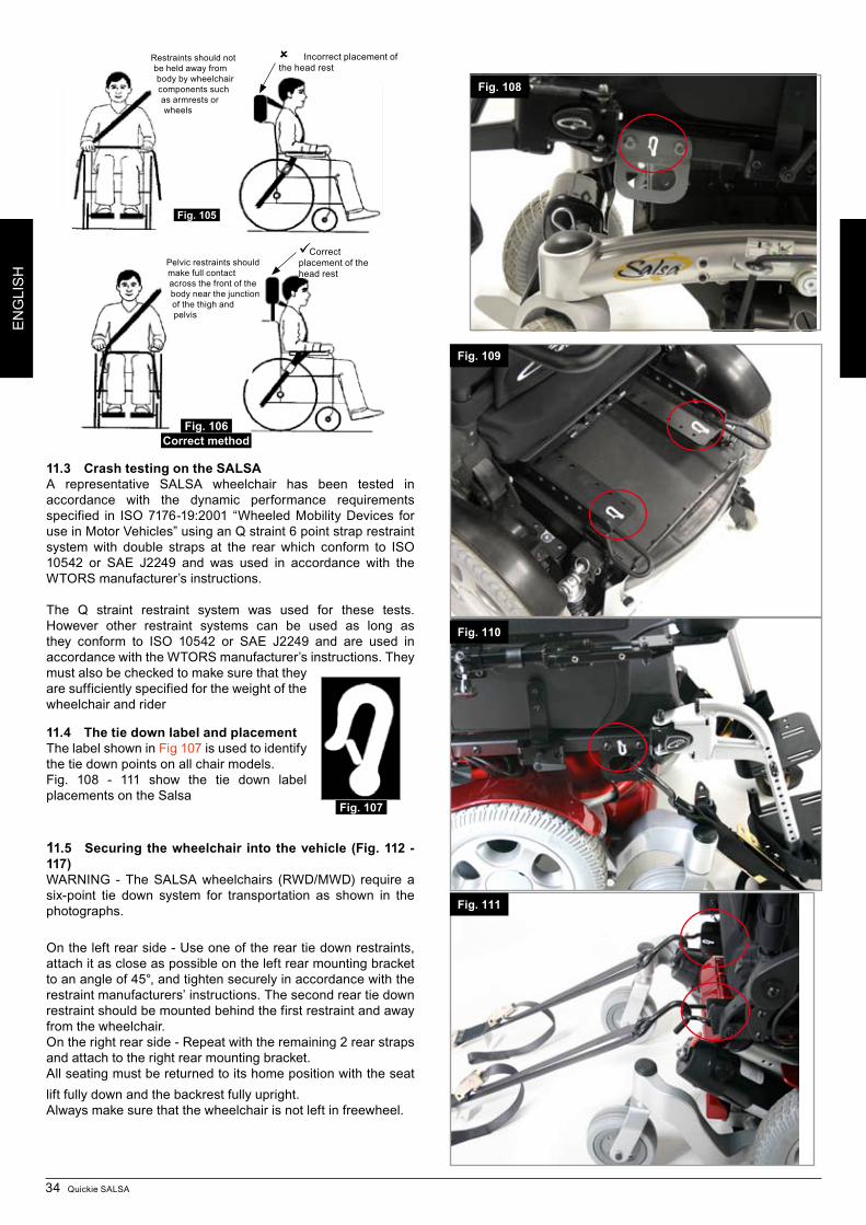
34 Quickie SALSA
EN
GLI
SH
11.3 Crash testing on the SALSAA representative SALSA wheelchair has been tested in accordance with the dynamic performance requirements specified in ISO 7176-19:2001 “Wheeled Mobility Devices for use in Motor Vehicles” using an Q straint 6 point strap restraint system with double straps at the rear which conform to ISO 10542 or SAE J2249 and was used in accordance with the WTORS manufacturer’s instructions.
The Q straint restraint system was used for these tests. However other restraint systems can be used as long as they conform to ISO 10542 or SAE J2249 and are used in accordance with the WTORS manufacturer’s instructions. They must also be checked to make sure that they are sufficiently specified for the weight of the wheelchair and rider
11.4 The tie down label and placementThe label shown in Fig 107 is used to identify the tie down points on all chair models. Fig. 108 - 111 show the tie down label placements on the Salsa
11.5 Securing the wheelchair into the vehicle (Fig. 112 - 117)WARNING - The SALSA wheelchairs (RWD/MWD) require a six-point tie down system for transportation as shown in the photographs.
On the left rear side - Use one of the rear tie down restraints, attach it as close as possible on the left rear mounting bracket to an angle of 45°, and tighten securely in accordance with the restraint manufacturers’ instructions. The second rear tie down restraint should be mounted behind the first restraint and away from the wheelchair. On the right rear side - Repeat with the remaining 2 rear straps and attach to the right rear mounting bracket.All seating must be returned to its home position with the seat lift fully down and the backrest fully upright.Always make sure that the wheelchair is not left in freewheel.
Restraints should not be held away from body by wheelchair components such as armrests or wheels
Incorrect placement of the head rest
Fig. 105
Pelvic restraints should make full contact across the front of the body near the junction of the thigh and pelvis
Correct placement of the head rest
Fig. 106Correct method
Fig. 107
Fig. 109
Fig. 110
Fig. 111
Fig. 108
EN
GLI
SH
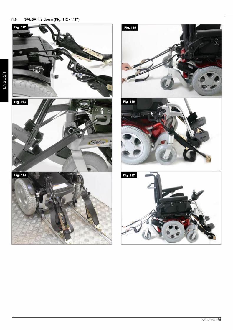
EASY 160, 160 HP 35
DE
UTS
CH
Fig. 112
Fig. 113
Fig. 114
11.6 SALSA tie down (Fig. 112 - 1117)
Fig. 117
Fig. 116
Fig. 115
EN
GLI
SH
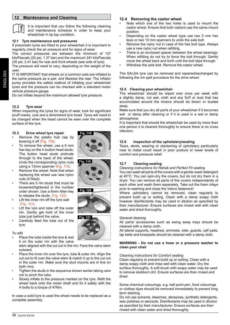
36 Quickie SALSA
EN
GLI
SH
12 Maintenance and Cleaning
It is important that you follow the following cleaning and maintenance schedule in order to keep your wheelchair in tip top condition.
12.1 Tyre maintenance and pressuresIf pneumatic tyres are fitted to your wheelchair it is important to regularly check the air pressure and for signs of wear.The correct pressures are between the minimum of 137 kiloPascals (20 psi, 1.37 bar) and the maximum 241 kiloPascals (35 psi, 2.41 bar) for rear and front wheels (see side of tyre).The pressure will need to vary, depending on the weight of the user. IT IS IMPORTANT that wheels on a common axle are inflated to the same pressure as a pair, and likewise the rear. The inflator pump provides the safest method of inflating your wheelchair tyres and the pressure can be checked with a standard motor vehicle pressure gauge.Do not inflate beyond the maximum allowed tyre pressure.
12.2 Tyre wearWhen inspecting the tyres for signs of wear, look for significant scuff marks, cuts and a diminished tyre tread. Tyres will need to be changed when the tread cannot be seen over the complete surface of the tyre.
12.3 Drive wheel tyre repair• Remove the plastic hub cap by
levering it off (Fig. 118). • Toremovethewheel,usea6mm
hex key on the 4-button head studs. The button head studs protrude through to the back of the wheel. Undo the corresponding nyloc nuts using a 13mm spanner (Fig. 119).
• Removethewheel.Notethatwhenreplacing the wheel use new nyloc nuts (if fitted).
• Thereare5rimstudsthatmustbeloosened/tightened in the number order shown. Use a 6mm Allen key to release the studs. (Fig. 120)
• Lifttheinnerrimoffthetyrewall (Fig. 121).• Lift the tyreand tubeoff theouter
rim. Gently get hold of the inner tube just behind the valve.
• Carefully feed the tube out of thetyre.
To refit• Placethetubeinsidethetyre&rest
it on the outer rim with the valve stem aligned with the cut out in the rim. Face the valve stem outward.
• Placetheinnerrimoverthetyre,tube&outerrim.Alignthecut out to fit over the valve stem & match it up to the cut out in the outer rim. Make sure the stud mounts are in line on both rims.
• Tightenthestudsinthesequenceshownearliertakingcarenot to pinch the tube.
• Slowlyinflatetothepressuremarkedonthetyre.Refitthewheel back onto the motor shaft and fix it safely with the 4-bolts to a torque of 47Nm.
In case a solid tyre is used the wheel needs to be replaced as a complete assembly.
12.4 Removing the castor wheel• Note which one of the two holes is used to mount the
castor wheel. Ensure that both castors use the same mount position.
• Depending on the castor wheel type use two 5mm hexkeys or two 13 mm spanners to undo the axle bolt.
• Removethenylocnutincaseofthehexbolttype.Alwaysuse a new nyloc nut when refitting.
• Thereisanenclosedspacerbetweenthewheelbearings.When refitting do not try to force the bolt through. Gently move the wheel back and forth until the bolt slips through.
• Withdrawtheaxlebolt.Removethecastorwheel.
The SALSA tyre can be removed and repaired/exchanged by following the rim split procedure for the drive wheel.
12.5 Cleaning your wheelchairThe wheelchair should be wiped over once per week with a slightly damp, not wet, cloth and any fluff or dust that has accumulated around the motors should be blown or dusted away.Make sure that you dry all parts of your wheelchair if it becomes wet or damp after cleaning or if it is used in a wet or damp atmosphere.It is important that should the wheelchair be used by more than one person it is cleaned thoroughly to ensure there is no cross infection.
12.6 Inspection of the upholstery/seatingTears, dents, wearing or slackening of upholstery particularly near to metal could result in poor posture or lower levels of comfort and pressure relief.
12.7 Cleaning seatingCleaning instructions for Rehab and Perfect Fit seatingYou can wash all parts of the covers with a gentle-wash detergent at 40°C. You can spin-dry the covers, but do not dry them in a dryer. You can remove all parts of the covers independently of each other and wash them separately. Take out the foam inlays prior to washing and close the Velcro fasteners! Where upholstery cannot be removed, clean regularly to prevent build up or soiling. Clean with a damp soapy cloth however disinfectants may be used in dilution as specified by their manufacturer. Ensure surfaces are rinsed well with clean water and dried thoroughly.
General cleaningAll parts/ accessories such as swing away trays should be cleaned with a damp cloth.All lateral supports, headrest, armrests, side- guards, calf pads, lap belts and kneepads should be cleaned with a damp cloth.
WARNING - Do not use a hose or a pressure washer to clean your chair
Cleaning instructions for Comfort seatingClean regularly to prevent build up or soiling. Clean with a damp soapy cloth and rinse well with clean water. Dry the surface thoroughly. A soft brush with soapy water may be used to remove stubborn dirt. Ensure surfaces are then rinsed and dried.
Some chemical colourings, e.g. ball point pen, food colourings or clothes dyes should be removed immediately to prevent long term staining.Do not use solvents, bleaches, abrasives, synthetic detergents, wax polishes or aerosols. Disinfectants may be used in dilution as specified by their manufacturer. Ensure surfaces are then rinsed with clean water and dried thoroughly.
Fig. 118
Fig. 119
Fig. 120
Fig. 121
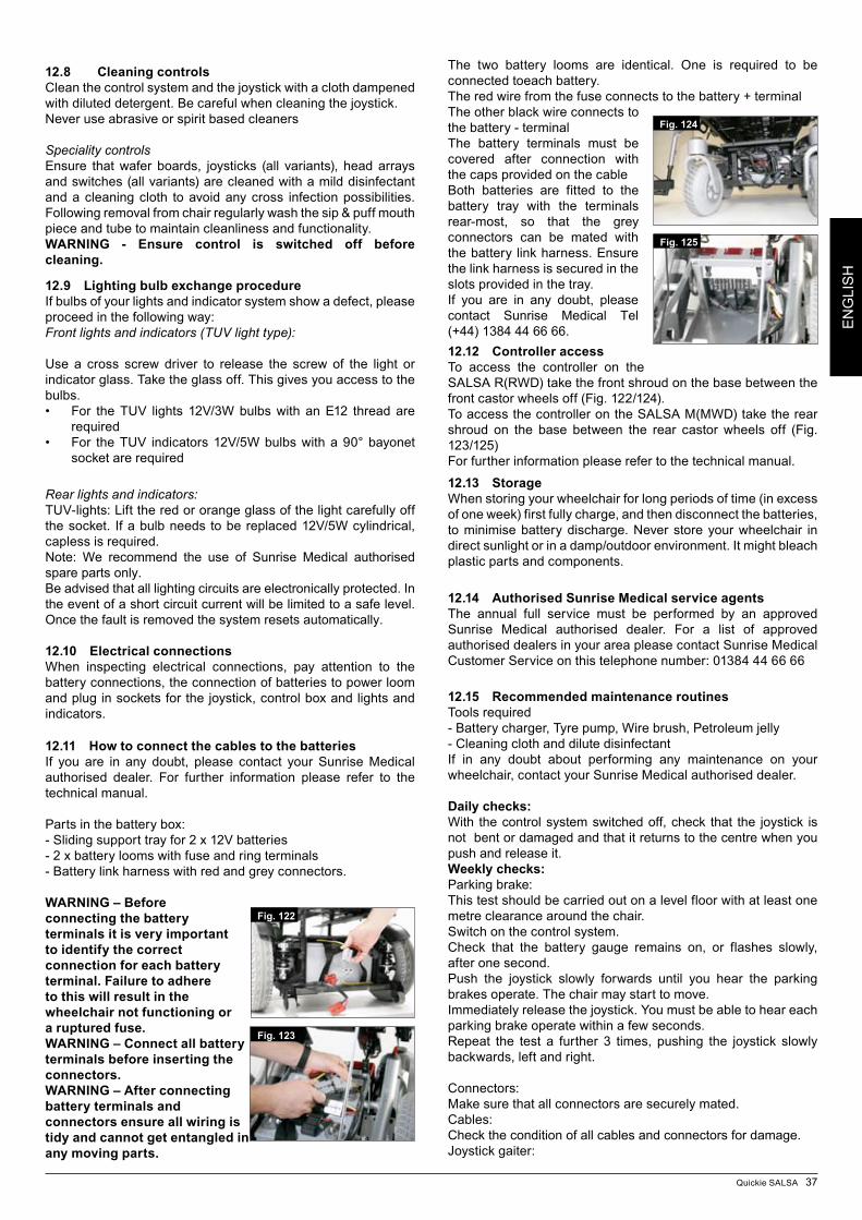
Quickie SALSA 37
EN
GLI
SH
12.8 Cleaning controlsClean the control system and the joystick with a cloth dampened with diluted detergent. Be careful when cleaning the joystick.Never use abrasive or spirit based cleaners
Speciality controlsEnsure that wafer boards, joysticks (all variants), head arrays and switches (all variants) are cleaned with a mild disinfectant and a cleaning cloth to avoid any cross infection possibilities. Following removal from chair regularly wash the sip & puff mouth piece and tube to maintain cleanliness and functionality.WARNING - Ensure control is switched off before cleaning.
12.9 Lighting bulb exchange procedureIf bulbs of your lights and indicator system show a defect, please proceed in the following way:Front lights and indicators (TUV light type):
Use a cross screw driver to release the screw of the light or indicator glass. Take the glass off. This gives you access to the bulbs.• For theTUV lights 12V/3Wbulbswith anE12 threadare
required• For theTUV indicators12V/5Wbulbswitha90°bayonet
socket are required
Rear lights and indicators:TUV-lights: Lift the red or orange glass of the light carefully off the socket. If a bulb needs to be replaced 12V/5W cylindrical, capless is required.Note: We recommend the use of Sunrise Medical authorised spare parts only. Be advised that all lighting circuits are electronically protect ed. In the event of a short circuit current will be limited to a safe level. Once the fault is removed the system resets automatically. 12.10 Electrical connectionsWhen inspecting electrical connections, pay attention to the battery connections, the connection of batteries to power loom and plug in sockets for the joystick, control box and lights and indicators.
12.11 How to connect the cables to the batteriesIf you are in any doubt, please contact your Sunrise Medical authorised dealer. For further information please refer to the technical manual.
Parts in the battery box:- Sliding support tray for 2 x 12V batteries- 2 x battery looms with fuse and ring terminals- Battery link harness with red and grey connectors.
WARNING – Before connecting the battery terminals it is very important to identify the correct connection for each battery terminal. Failure to adhere to this will result in the wheelchair not functioning or a ruptured fuse.WARNING – Connect all battery terminals before inserting the connectors.WARNING – After connecting battery terminals and connectors ensure all wiring is tidy and cannot get entangled in any moving parts.
The two battery looms are identical. One is required to be connected toeach battery. The red wire from the fuse connects to the battery + terminalThe other black wire connects to the battery - terminalThe battery terminals must be covered after connection with the caps provided on the cableBoth batteries are fitted to the battery tray with the terminals rear-most, so that the grey connectors can be mated with the battery link harness. Ensure the link harness is secured in the slots provided in the tray.If you are in any doubt, please contact Sunrise Medical Tel (+44) 1384 44 66 66.12.12 Controller accessTo access the controller on the SALSA R(RWD) take the front shroud on the base between the front castor wheels off (Fig. 122/124).To access the controller on the SALSA M(MWD) take the rear shroud on the base between the rear castor wheels off (Fig. 123/125)For further information please refer to the technical manual.
12.13 StorageWhen storing your wheelchair for long periods of time (in excess of one week) first fully charge, and then disconnect the batteries, to minimise battery discharge. Never store your wheelchair in direct sunlight or in a damp/outdoor environment. It might bleach plastic parts and components.
12.14 Authorised Sunrise Medical service agentsThe annual full service must be performed by an approved Sunrise Medical authorised dealer. For a list of approved authorised dealers in your area please contact Sunrise Medical Customer Service on this telephone number: 01384 44 66 66
12.15 Recommended maintenance routinesTools required- Battery charger, Tyre pump, Wire brush, Petroleum jelly- Cleaning cloth and dilute disinfectantIf in any doubt about performing any maintenance on your wheelchair, contact your Sunrise Medical authorised dealer.
Daily checks:With the control system switched off, check that the joystick is not bent or damaged and that it returns to the centre when you push and release it.Weekly checks:Parking brake:This test should be carried out on a level floor with at least one metre clearance around the chair.Switch on the control system.Check that the battery gauge remains on, or flashes slowly, after one second.Push the joystick slowly forwards until you hear the parking brakes operate. The chair may start to move.Immediately release the joystick. You must be able to hear each parking brake operate within a few seconds.Repeat the test a further 3 times, pushing the joystick slowly backwards, left and right.
Connectors:Make sure that all connectors are securely mated.Cables:Check the condition of all cables and connectors for damage.Joystick gaiter:
Fig. 122
Fig. 124
Fig. 125
Fig. 123
38 Quickie SALSA
EN
GLI
SH
Check the thin rubber gaiter or boot around the base of the joystick shaft for damage or splitting. Check visually only, do not handle the gaiter.
Mounting:Make sure that all components of the control system are securely mounted. Do not over-tighten any securing screws.
WARNING - Please refer to Service manual for any information about Torques.
12.16 Performance checksAfter performing any maintenance or repairs on the wheelchair you must make sure that it is functioning correctly before it is used.
• Visuallyinspectthewheelchairtomakesurethelegrests,armrests etc are correctly positioned and attached to the wheelchair and all fasteners are sufficiently tightened.
• Make sure that the backrest is correctly fitted andadjusted.
• Makesurethatallofthecushionsareinplace• Switch on the hand control – Do the lights flash? This
signifies that there is a fault in the electronic system. Refer to section 8 for basic troubleshooting.
• Performtheparkingbrakecheck.• Operate all of the electric options, including lights and
indicators (if fitted) to make sure that they work correctly.• Withtheseatinginanelevatedposition,drivethewheelchair
to make sure that the ‘creep’ mode works which will slow the wheelchair.
• Drivethewheelchair ineachof thedriveprofiles tomakesure the wheelchair performs as it did before.
If you are in any doubt about the performance requirements of your wheelchair contact your Sunrise Medical authorised dealer.
Maintenance & Inspection Schedule
Daily
Weekly
Quarterly
Six m
onth
Annually
Check battery level indicator and charge if necessary
¯
Check the joystick of the hand control is not bent or damaged
¯
Ensure all removable parts are securely fastened
¯
Check lapstrap for wear and make sure the buckle is operational
¯
Parking brake test
¯
Check tyres and inflate
¯
Ensure lights and indicators are operational and clean
¯
Ensure all cables and connectors are sound and are tidy and out of the way
¯
Clean wheelchair and upholstery
¯
Battery terminal inspection – Remove any corrosion and apply Vaseline
¯
Check upholstery, seating, headrests, armpads and calfpads for wear
¯
Complete inspection, safety check and service should be made by a Sunrise Medical authorised dealer
¯
Fastener Matrix Torque Setting (Nm)
M3 Bolt / Stud 1M4 Bolt / Stud 2.5 - 3M5 Bolt / Stud 5 - 6M6 Bolt / Stud 9 - 10
M8 Bolt / Stud 19 - 20 (15 Nm for all backrest screws)
M10 Bolt / Stud 30 Nm (5Nm on manual & electric backrest recline
M12 Bolt / Stud 47.5M16 Bolt / Stud 54No6 Screw 1.5Castor fork nut & bolt 25Castor wheel axle 19Drive wheel hub studs 25
The table shown above contains generic torque values set out as an industry standard. Therewillbespecifictorquesettingrequiredforsometasks.Ifspecifictorquesarerequired,thevalueineachinstancewillbe contained within the text description, title or clearly labelled within the photo.
It will be necessary to use a torque wrench. It is higly recom-mendedthatallspecificinstructionmanualsandsafetyrecom-mendations supplied with the torque wrench, should be read and understood before such equioments is used.It is recommended that all mandatory safety procedures are strictly adhered to.No responsibility is accepted by Sunrise Medical for any con-sequence, directly or indirectly, resulting from incorrect use of tools / equipment during any service procedure pertaining to this or other Technical / Workshop Manuals issued by Sunrise Medical.
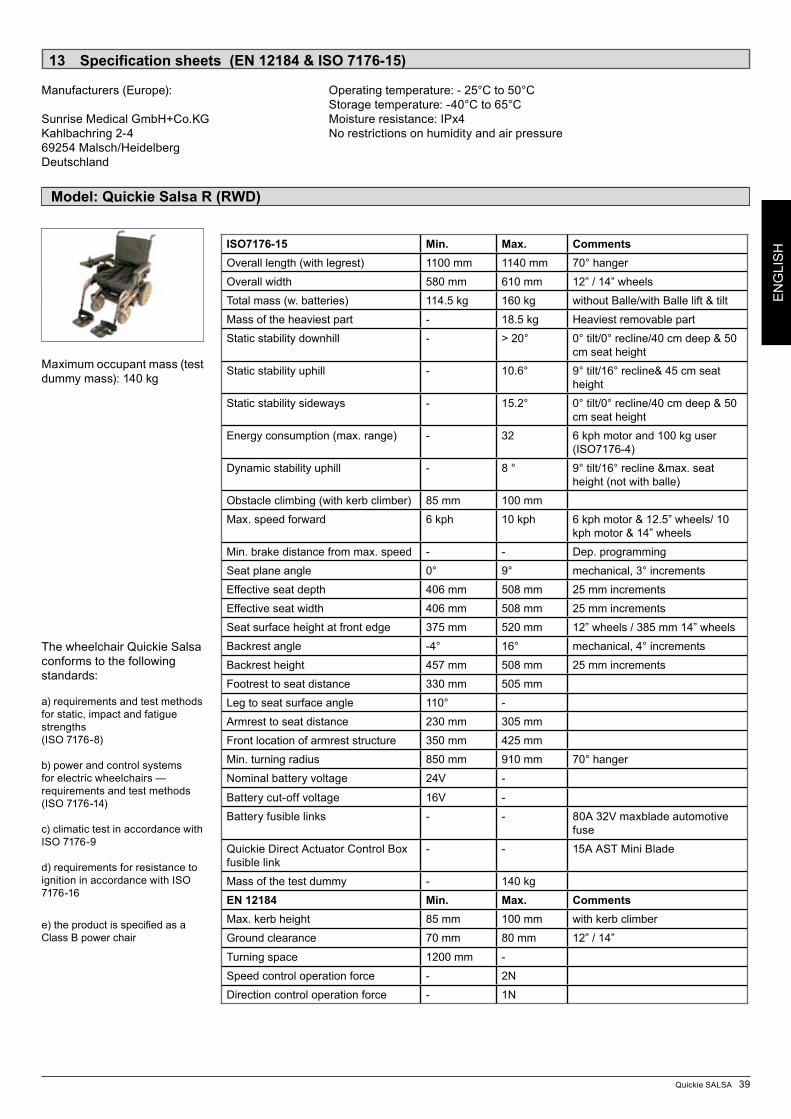
Quickie SALSA 39
EN
GLI
SH
Model: Quickie Salsa R (RWD)
Specification sheets (EN 12184 & ISO 7176-15)13
Manufacturers (Europe): Operating temperature: - 25°C to 50°C Storage temperature: -40°C to 65°CSunrise Medical GmbH+Co.KG Moisture resistance: IPx4Kahlbachring 2-4 No restrictions on humidity and air pressure69254 Malsch/HeidelbergDeutschland
Maximum occupant mass (test dummy mass): 140 kg
The wheelchair Quickie Salsa conforms to the following standards:
a) requirements and test methods for static, impact and fatigue strengths (ISO 7176-8)
b) power and control systems for electric wheelchairs — requirements and test methods (ISO 7176-14) c) climatic test in accordance with ISO 7176-9 d) requirements for resistance to ignition in accordance with ISO 7176-16
e)theproductisspecifiedasaClass B power chair
ISO7176-15 Min. Max. CommentsOverall length (with legrest) 1100 mm 1140 mm 70° hanger
Overall width 580 mm 610 mm 12” / 14” wheels
Total mass (w. batteries) 114.5 kg 160 kg without Balle/with Balle lift & tilt
Mass of the heaviest part - 18.5 kg Heaviest removable part
Static stability downhill - > 20° 0° tilt/0° recline/40 cm deep & 50 cm seat height
Static stability uphill - 10.6° 9° tilt/16° recline& 45 cm seat height
Static stability sideways - 15.2° 0° tilt/0° recline/40 cm deep & 50 cm seat height
Energy consumption (max. range) - 32 6 kph motor and 100 kg user (ISO7176-4)
Dynamic stability uphill - 8 ° 9° tilt/16° recline &max. seat height (not with balle)
Obstacle climbing (with kerb climber) 85 mm 100 mm
Max. speed forward 6 kph 10 kph 6 kph motor & 12.5” wheels/ 10 kph motor & 14” wheels
Min. brake distance from max. speed - - Dep. programming
Seat plane angle 0° 9° mechanical, 3° increments
Effective seat depth 406 mm 508 mm 25 mm increments
Effective seat width 406 mm 508 mm 25 mm increments
Seat surface height at front edge 375 mm 520 mm 12” wheels / 385 mm 14” wheels
Backrest angle -4° 16° mechanical, 4° increments
Backrest height 457 mm 508 mm 25 mm increments
Footrest to seat distance 330 mm 505 mm
Leg to seat surface angle 110° -
Armrest to seat distance 230 mm 305 mm
Front location of armrest structure 350 mm 425 mm
Min. turning radius 850 mm 910 mm 70° hanger
Nominal battery voltage 24V -
Battery cut-off voltage 16V -
Battery fusible links - - 80A 32V maxblade automotive fuse
Quickie Direct Actuator Control Box fusible link
- - 15A AST Mini Blade
Mass of the test dummy - 140 kg
EN 12184 Min. Max. CommentsMax. kerb height 85 mm 100 mm with kerb climber
Ground clearance 70 mm 80 mm 12” / 14”
Turning space 1200 mm -
Speed control operation force - 2N
Direction control operation force - 1N
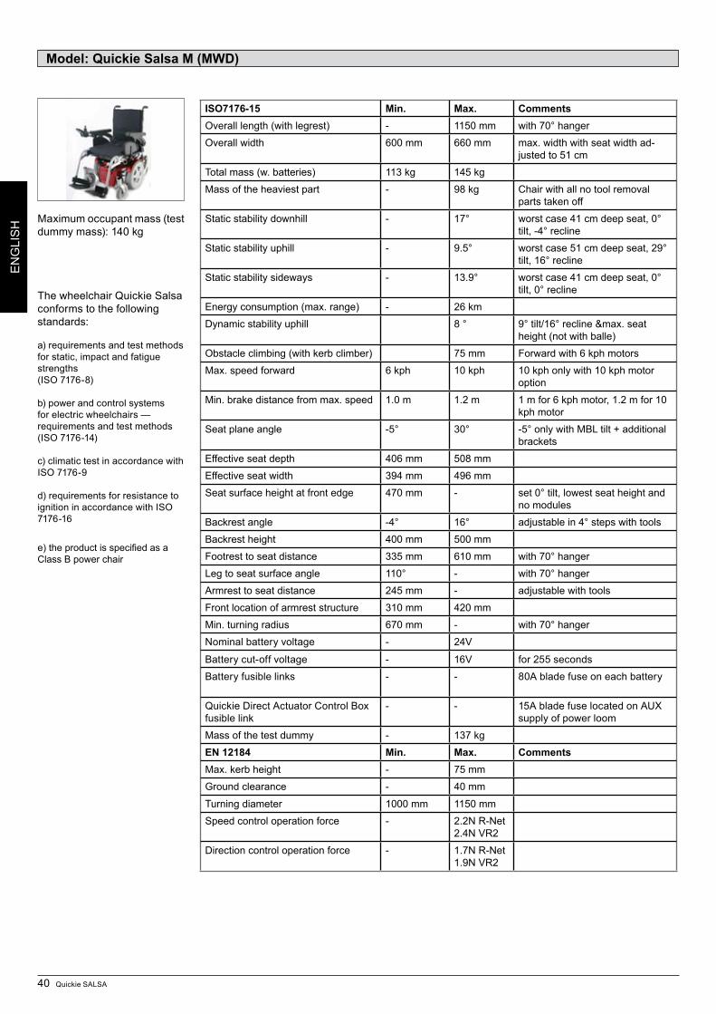
40 Quickie SALSA
EN
GLI
SH
Model: Quickie Salsa M (MWD)
Maximum occupant mass (test dummy mass): 140 kg
The wheelchair Quickie Salsa conforms to the following standards:
a) requirements and test methods for static, impact and fatigue strengths (ISO 7176-8)
b) power and control systems for electric wheelchairs — requirements and test methods (ISO 7176-14) c) climatic test in accordance with ISO 7176-9 d) requirements for resistance to ignition in accordance with ISO 7176-16
e)theproductisspecifiedasaClass B power chair
ISO7176-15 Min. Max. CommentsOverall length (with legrest) - 1150 mm with 70° hanger
Overall width 600 mm 660 mm max. width with seat width ad-justed to 51 cm
Total mass (w. batteries) 113 kg 145 kg
Mass of the heaviest part - 98 kg Chair with all no tool removal parts taken off
Static stability downhill - 17° worst case 41 cm deep seat, 0° tilt, -4° recline
Static stability uphill - 9.5° worst case 51 cm deep seat, 29° tilt, 16° recline
Static stability sideways - 13.9° worst case 41 cm deep seat, 0° tilt, 0° recline
Energy consumption (max. range) - 26 km
Dynamic stability uphill 8 ° 9° tilt/16° recline &max. seat height (not with balle)
Obstacle climbing (with kerb climber) 75 mm Forward with 6 kph motors
Max. speed forward 6 kph 10 kph 10 kph only with 10 kph motor option
Min. brake distance from max. speed 1.0 m 1.2 m 1 m for 6 kph motor, 1.2 m for 10 kph motor
Seat plane angle -5° 30° -5° only with MBL tilt + additional brackets
Effective seat depth 406 mm 508 mm
Effective seat width 394 mm 496 mm
Seat surface height at front edge 470 mm - set 0° tilt, lowest seat height and no modules
Backrest angle -4° 16° adjustable in 4° steps with tools
Backrest height 400 mm 500 mm
Footrest to seat distance 335 mm 610 mm with 70° hanger
Leg to seat surface angle 110° - with 70° hanger
Armrest to seat distance 245 mm - adjustable with tools
Front location of armrest structure 310 mm 420 mm
Min. turning radius 670 mm - with 70° hanger
Nominal battery voltage - 24V
Battery cut-off voltage - 16V for 255 seconds
Battery fusible links - - 80A blade fuse on each battery
Quickie Direct Actuator Control Box fusible link
- - 15A blade fuse located on AUX supply of power loom
Mass of the test dummy - 137 kg
EN 12184 Min. Max. CommentsMax. kerb height - 75 mm
Ground clearance - 40 mm
Turning diameter 1000 mm 1150 mm
Speed control operation force - 2.2N R-Net 2.4N VR2
Direction control operation force - 1.7N R-Net 1.9N VR2
Quickie SALSA 41
EN
GLI
SH
Service History14 This section is designed to assist you in keeping a record of any service and repairs to your wheelchair. Should you decide to sell or exchange your vehicle in the future, this will prove most helpful to you. Your Service Agent will also benefit from a documented record and this manual should accompany the wheelchair when service or repair work is carried out. The Service Agent will complete this section and return the manual to you. All our scooters, wheelchairs and power chairs undergo rigorous tests to ensure that they meet our requirements of comfort, safety and durability. Our success is based on the strong traditions of quality, value for money and genuinely caring for our customers. We pride ourselves not only on designing and building the most innovative products but also on our commitment to offer an excellent standard of customer service both during and after sale.
Disposal15
The symbols below mean that in accordance with local laws and regulations your product should be disposed of separately from household waste. When this product reaches the end of its life, take it to the local collection point designated by local authorities. The separate collection and recycling of your product at the time of disposal will help conserve natural resources and ensure that it is recycled in a manner that protects the environment.
Ensure you are the legal owner of the product prior to arranging for the product disposal in accordance with the above recommendations.
Dealer signature and stamp:Dealer signature and stamp:
Dealer signature and stamp:Dealer signature and stamp:
Model Serial NoYear 1 2 3 4 Year 1 2 3 4Date DateController ChassisOn/Off switch ConditionOutput plug SteeringJoystick UpholsteryBrakes SeatProgrammable configuration BackrestBatteries ArmrestsLevel ElectricsConnections Condition of loomDischarge level ConnectionsWheels Test runWear ForwardsPressure ReverseBearings Emergency stopWheel nuts Left turnMotors Right turnWiring Up/Down slopeConnections Over obstaclesNoise Parking brakeBrakes Note: Only use Sunrise Medical parts for service and repairsBrushes
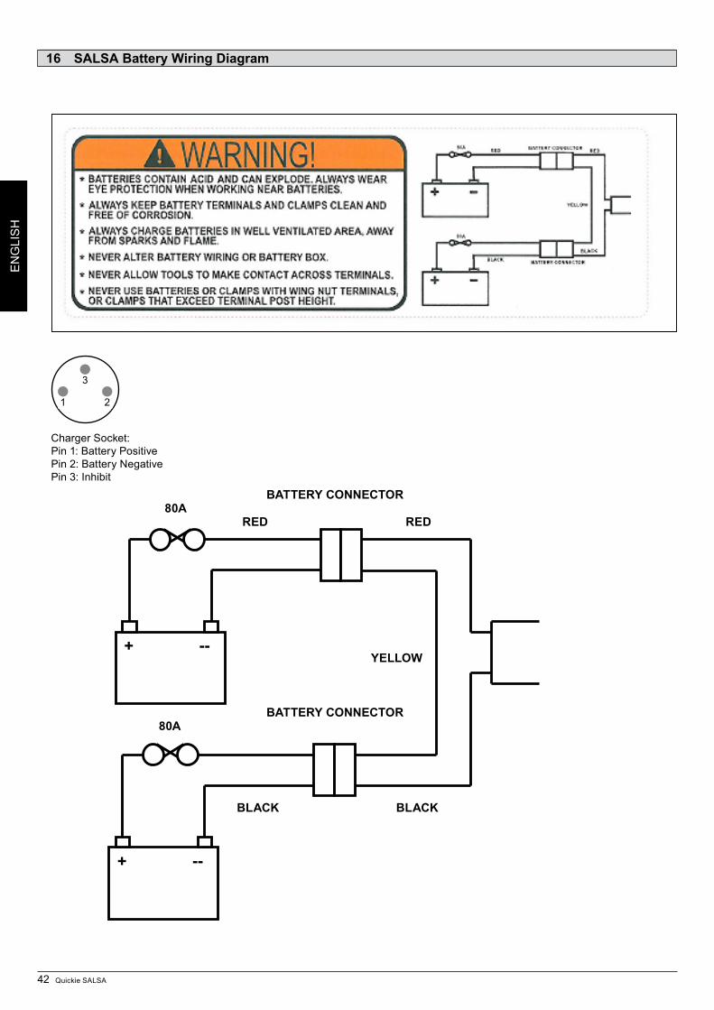
42 Quickie SALSA
EN
GLI
SH
SALSA Battery Wiring Diagram16
Charger Socket:Pin 1: Battery PositivePin 2: Battery NegativePin 3: Inhibit
1 2
3
+ --
+ --
80A
80A
BLACK BLACK
RED RED
YELLOW
BATTERY CONNECTOR
BATTERY CONNECTOR

Sunrise Medical GmbH69254 Malsch/HeidelbergGermanyTel.: +49 (0) 7253/980-460Fax: +49 (0) 7253/980-220www.sunrisemedical.com
Sunrise Medical LimitedHigh Street WollastonWest Midlands DY8 4PSEnglandTel.: +44 (0) 1384446688www.sunrisemedical.com
Sunrise Medical S.L.Polígono Bakiola, 4148498 Arrankudiaga – VizcayaEspañaTel.: +34 (0) 902142434Fax: +34 (0) 946481575www.sunrisemedical.es
Sunrise Medical S.A.13, Rue de la Painguetterie37390 Chanceaux sur ChoisilleFranceTel.: +33 (0) 247554400Fax: +33 (0) 247554403www.sunrisemedical.com
Sunrise Medical SrlVia Riva 20, Montale29100 Piacenza (PC)ItalyTel.: +39 (0) 0523-573111Fax: +39 (0) 0523-57060www.sunrisemedical.it
Sunrise Medical A.G.Lückhalde 143074 Muri bei BernSwitzerlandTel.: +41 (0) 31-958-3838Fax: +41 (0) 31-958-3848www.sunrisemedical.ch
Sunrise Medical ASRehabsenteret1450 NesoddtangenNorwayTel.: +47 (0) 66963800Faks: +47 (0) 66963838www.sunrisemedical.no
Sunrise Medical ABBritta Sahlgrens gata 8A42131 Västra FrölundaSwedenTel: +46 (0) 31-748 37 00Fax: +46 (0) 31-748 37 37www.sunrisemedical.se
Sunrise Medical B.V.Pascalbaan 33439 MP NieuwegeinNetherlandsTel.: +31 (0) 3060-82100Fax: +31 (0) 3060-55880www.sunrisemedical.com
M.M.S. Medical Ltd.Forge Hill Cross, Kinsale RoadCorkIrelandTel.: +35 (0) 3214314111Fax: +35 (0) 3214962792
G2 A/SGraham Bells Vej 21-23 A8200 Arhus NDenmarkTel.: +45 (0) 86286088Fax: +45 (0) 86286588www.G2.dk
0403/6/ST-000690613 EMSE/D/F/I/NL
Sunrise Medical GmbH & Co.KGKahlbachring 2-469254 Malsch/HeidelbergGermanyTel.: +49 (0) 7253/980-0Fax: +49 (0) 7253/980-111www.sunrisemedical.com
Sunrise Medical LimitedHigh Street WollastonWest Midlands DY8 4PSEnglandTel.: +44 (0) 1384446666www.sunrisemedical.com
Sunrise Medical S.L.Polígono Bakiola, 4148498 Arrankudiaga – VizcayaEspañaTel.: +34 (0) 902142434Fax: +34 (0) 946481575www.sunrisemedical.com
Sunrise Medical S.A.13, Rue de la Painguetterie37390 Chanceaux sur ChoisilleFranceTel.: +33 (0) 247554400Fax: +33 (0) 247554403www.sunrisemedical.com
Sunrise Medical SrlVia Riva 20, Montale29100 Piacenza (PC)ItalyTel.: +39 0523-573111Fax: +39 0523-570060www.sunrisemedical.com
Sunrise Medical A.G.Lückhalde 143074 Muri bei BernSwitzerlandTel.: +41 (0) 31-958-3838Fax: +41 (0) 31-958-3848www.sunrisemedical.com
Sunrise Medical ASRehabsenteret1450 NesoddtangenNorwayTel.: +47 (0) 66963880Faks: +47 (0) 66963880www.sunrisemedical.com
Sunrise Medical ABBritta Sahlgrens gata 8A421 31 Västra FrölundaSwedenTel: +46 (0) 31-748 37 00Fax: +46 (0) 31-748 37 37www.sunrisemedical.com
Sunrise Medical B.V.Groningenhaven 18-203433 PE NieuwegeinNederlandsTel.: +31 (0) 3060-82100Fax: +31 (0) 3060-55880www.sunrisemedical.com
G2 A/SGraham Bells Vej 21-23 A8200 Arhus NDenmarkTel.: +45 87 41 31 00Fax: +45 87 41 31 31www.G2.dk
25 01 2010 Salsa / Salsa M Rev. 2