Embed Size (px)
Citation preview
Steam Trap
5
Ste
am
Tra
p
www.yoshitake.jp5 -7
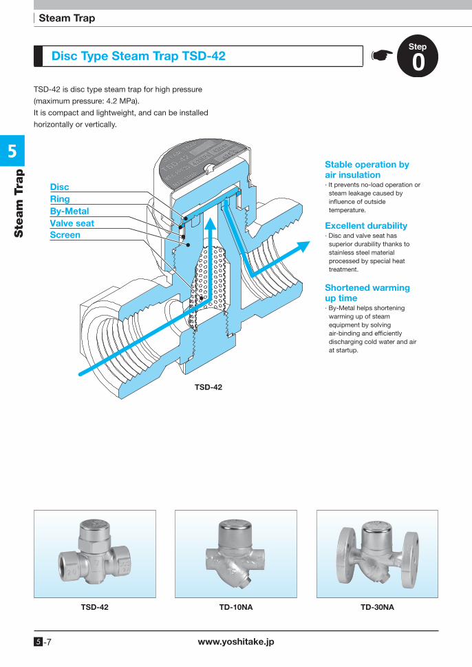
Disc Type Steam Trap TSD-42
TSD-42 is disc type steam trap for high pressure
(maximum pressure: 4.2 MPa).
It is compact and lightweight, and can be installed
horizontally or vertically.
TSD-42
DiscRing
Valve seatBy-Metal
Screen
Stable operation by air insulation∙ It prevents no-load operation or
steam leakage caused by in�uence of outside temperature.
Shortened warming up time∙ By-Metal helps shortening
warming up of steam equipment by solving air-binding and ef�ciently discharging cold water and air at startup.
Excellent durability∙ Disc and valve seat has
superior durability thanks to stainless steel material processed by special heat treatment.
TSD-42 TD-10NA TD-30NA
5
www.yoshitake.jp 5 -34
Steam Trap
Ste
am
Tra
p
Bucket Float Disc Bellows
Wafer By-pass Stainless steelBimetal
Right to Left Down to Up Up to DownConnector
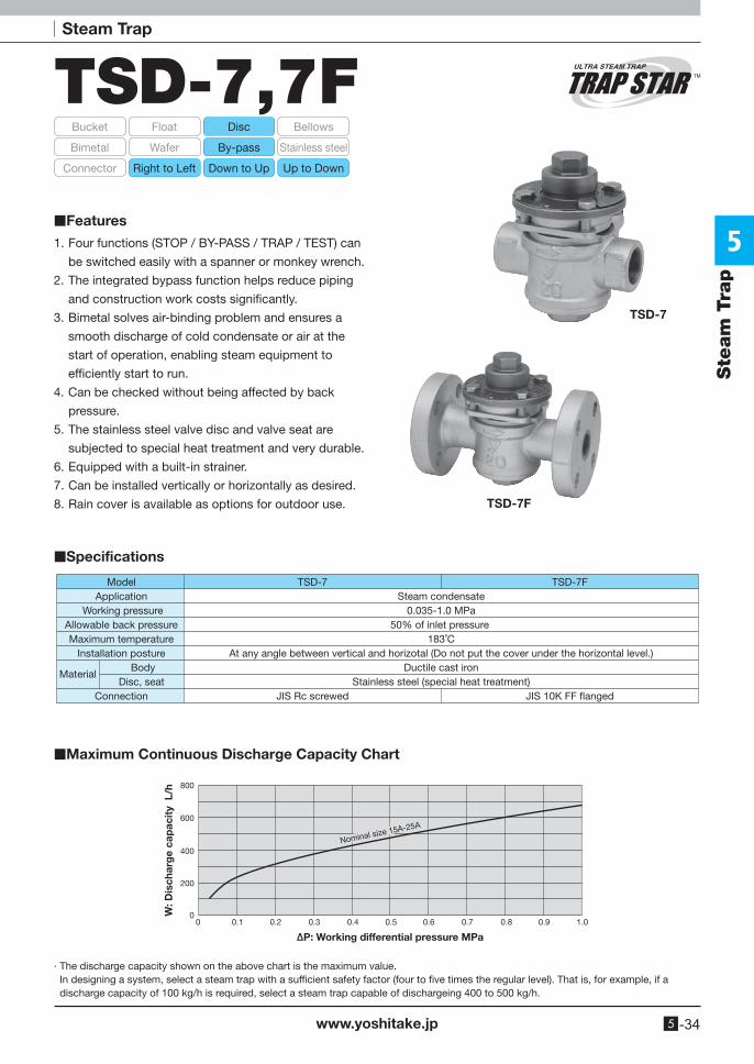
TSD-7,7F
TSD-7
TSD-7F
1. Four functions (STOP / BY-PASS / TRAP / TEST) can
be switched easily with a spanner or monkey wrench.
2. The integrated bypass function helps reduce piping
and construction work costs significantly.
3. Bimetal solves air-binding problem and ensures a
smooth discharge of cold condensate or air at the
start of operation, enabling steam equipment to
efficiently start to run.
4. Can be checked without being affected by back
pressure.
5. The stainless steel valve disc and valve seat are
subjected to special heat treatment and very durable.
6. Equipped with a built-in strainer.
7. Can be installed vertically or horizontally as desired.
8. Rain cover is available as options for outdoor use.
■Specifications
■Features
■Maximum Continuous Discharge Capacity Chart
TSD-7
JIS Rc screwed
ModelApplication
Working pressureAllowable back pressureMaximum temperature
Installation posture Body
Disc, seatConnection
TSD-7F
JIS 10K FF �anged
Steam condensate0.035-1.0 MPa
50% of inlet pressure 183˚C
At any angle between vertical and horizotal (Do not put the cover under the horizontal level.)Ductile cast iron
Stainless steel (special heat treatment)Material
200
0
400
600
800
0.10 0.2 0.3 0.4 0.5 0.6 0.7 0.8 0.9 1.0
W: D
isch
arg
e ca
pac
ity
L/h
∆P: Working differential pressure MPa
Nominal size 15A-25A
· The discharge capacity shown on the above chart is the maximum value. In designing a system, select a steam trap with a sufficient safety factor (four to five times the regular level). That is, for example, if a
discharge capacity of 100 kg/h is required, select a steam trap capable of dischargeing 400 to 500 kg/h.
5
www.yoshitake.jp5 -35
Ste
am
Tra
pTSD-7, 7F
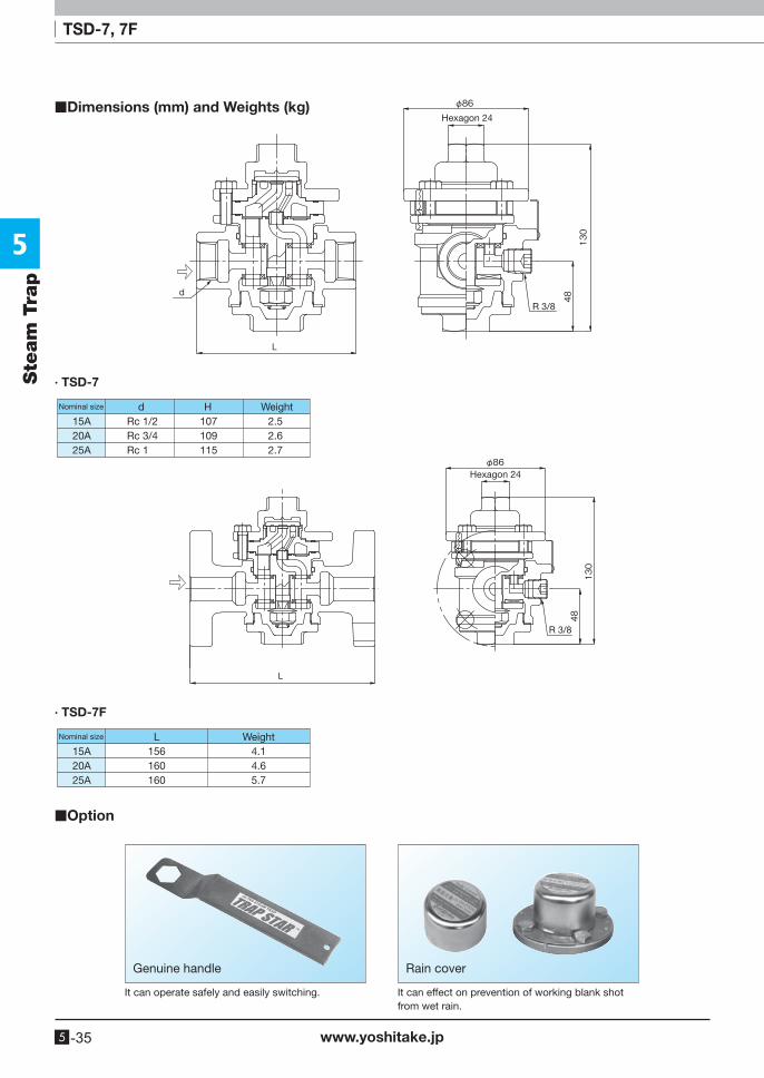
Hexagon 24
R 3/8
· TSD-7
Nominal size H Weightd2.52.62.7
15A20A25A
107109115
Rc 1/2Rc 3/4Rc 1
Hexagon 24
R 3/8
· TSD-7F
Nominal size WeightL15A20A25A
4.14.65.7
156160160
■Dimensions (mm) and Weights (kg)
■Option
Rain coverGenuine handle
It can operate safely and easily switching. It can effect on prevention of working blank shot from wet rain.
5
www.yoshitake.jp 5 -36
Steam Trap
Ste
am
Tra
p
STO
P
TRA
P
TES
T
BY
-P
AS
S
STOP
TRAPTEST
BY-PASS
TEST
BY-PASS
TRAP
STOP
TEST
BY-
PASSTRAP
STOP
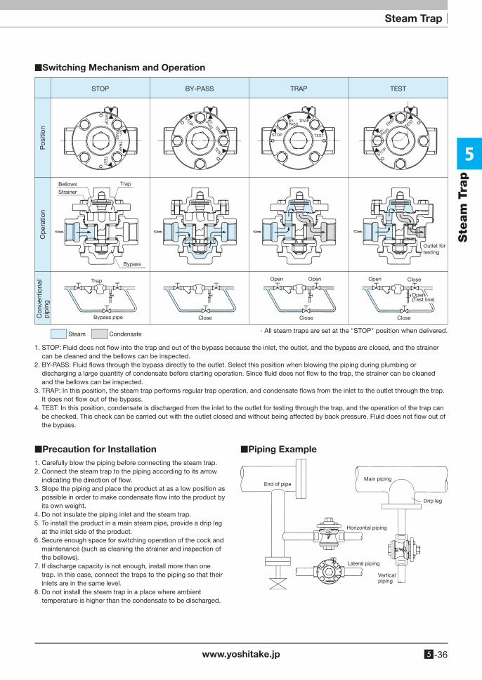
STOP BY-PASS TRAP TEST
CondensateSteam
Trap
Bypass
TrapBellows
Pos
ition
Con
vent
iona
lp
ipin
gO
per
atio
n
Strainer
Bypass pipe Close Close
Open Open Open
Open(Test line)
Outlet for testing
Close
Close
· All steam traps are set at the "STOP" position when delivered.
1. STOP: Fluid does not flow into the trap and out of the bypass because the inlet, the outlet, and the bypass are closed, and the strainer can be cleaned and the bellows can be inspected.
2. BY-PASS: Fluid flows through the bypass directly to the outlet. Select this position when blowing the piping during plumbing or discharging a large quantity of condensate before starting operation. Since fluid does not flow to the trap, the strainer can be cleaned and the bellows can be inspected.
3. TRAP: In this position, the steam trap performs regular trap operation, and condensate flows from the inlet to the outlet through the trap. It does not flow out of the bypass.
4. TEST: In this position, condensate is discharged from the inlet to the outlet for testing through the trap, and the operation of the trap can be checked. This check can be carried out with the outlet closed and without being affected by back pressure. Fluid does not flow out of the bypass.
1. Carefully blow the piping before connecting the steam trap.2. Connect the steam trap to the piping according to its arrow
indicating the direction of flow.3. Slope the piping and place the product at as a low position as
possible in order to make condensate flow into the product by its own weight.
4. Do not insulate the piping inlet and the steam trap.5. To install the product in a main steam pipe, provide a drip leg
at the inlet side of the product.6. Secure enough space for switching operation of the cock and
maintenance (such as cleaning the strainer and inspection of the bellows).
7. If discharge capacity is not enough, install more than one trap. In this case, connect the traps to the piping so that their inlets are in the same level.
8. Do not install the steam trap in a place where ambient temperature is higher than the condensate to be discharged.
Main piping
Horizontal piping
Lateral piping
End of pipe
Drip leg
Vertical piping
■Switching Mechanism and Operation
■Precaution for Installation ■Piping Example
5
www.yoshitake.jp5 -37
Steam TrapSte
am
Tra
p
Bucket Float Disc Bellows
Wafer By-pass Stainless steelBimetal
Right to Left Down to Up Up to DownConnector
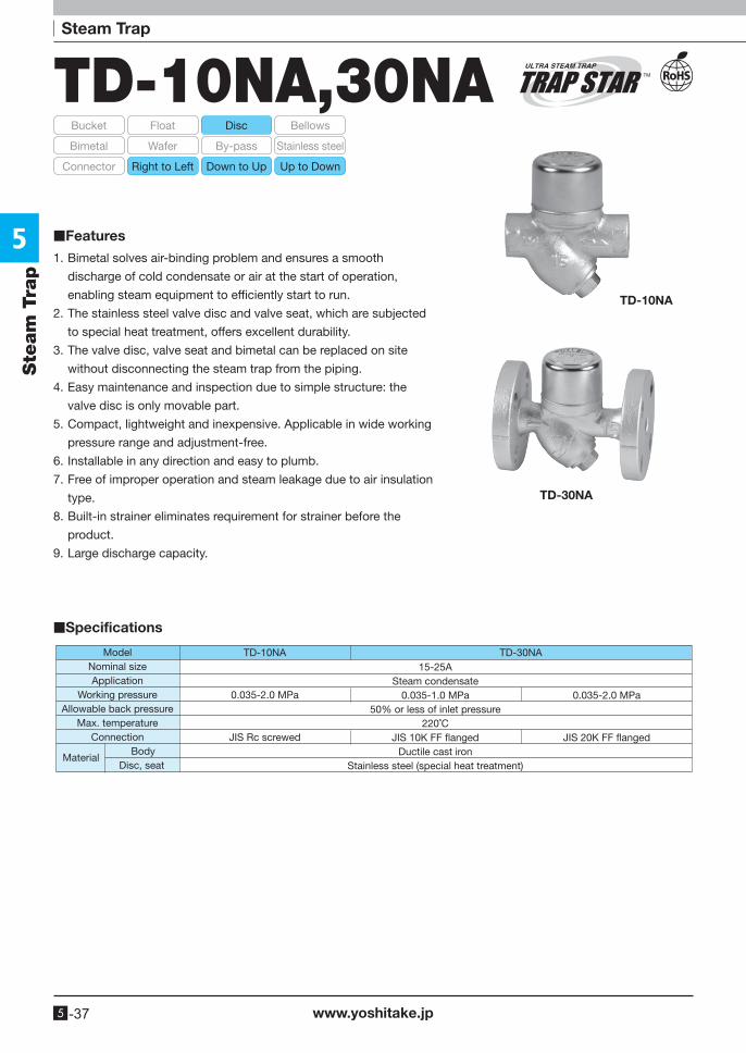
TD-10NA,30NA
TD-10NA
0.035-2.0 MPa
JIS Rc screwed
TD-30NA15-25A
Steam condensate0.035-1.0 MPa
50% or less of inlet pressure220˚C
JIS 10K FF �angedDuctile cast iron
Stainless steel (special heat treatment)
0.035-2.0 MPa
JIS 20K FF �anged
ModelNominal sizeApplication
Working pressureAllowable back pressure
Max. temperatureConnection
Body Disc, seat
Material
TD-10NA
TD-30NA
1. Bimetal solves air-binding problem and ensures a smooth
discharge of cold condensate or air at the start of operation,
enabling steam equipment to efficiently start to run.
2. The stainless steel valve disc and valve seat, which are subjected
to special heat treatment, offers excellent durability.
3. The valve disc, valve seat and bimetal can be replaced on site
without disconnecting the steam trap from the piping.
4. Easy maintenance and inspection due to simple structure: the
valve disc is only movable part.
5. Compact, lightweight and inexpensive. Applicable in wide working
pressure range and adjustment-free.
6. Installable in any direction and easy to plumb.
7. Free of improper operation and steam leakage due to air insulation
type.
8. Built-in strainer eliminates requirement for strainer before the
product.
9. Large discharge capacity.
■Specifications
■Features
5
www.yoshitake.jp 5 -38
Ste
am
Tra
p
TD-10NA, 30NA
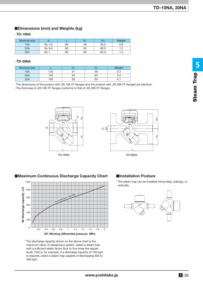
■Dimensions (mm) and Weights (kg)· TD-10NA
Nominal size15A20A25A
Weight0.91.21.4
dRc 1/2Rc 3/4Rc 1
L909090
H1
495356
H2
55.560.562.5
Nominal size15A20A25A
Weight2.33.44.1
L125140150
H1
515465
H2
596363
· TD-30NA
· The dimensions of the product with JIS 10K FF flanged and the product with JIS 20K FF flanged are identical.· The thickness of JIS 10K FF flanges conforms to that of JIS 20K FF flanges.
1200
1000
800
600
400
200
00.2 0.4 0.6 0.8 1 1.2 1.4 1.6 1.8 2
W: D
isch
arg
e ca
pac
ity
L/h
∆P: Working differential pressure MPa
Nominal size 15A-25A
■Maximum Continuous Discharge Capacity Chart ■Installation Posture
* The discharge capacity shown on the above chart is the maximum value. In designing a system, select a steam trap with a sufficient safety factor (four to five times the regular level). That is, for example, if a discharge capacity of 100 kg/h is required, select a steam trap capable of discharging 400 to 500 kg/h.
* The steam trap can be installed horizontally, sidlingly, or vertically.
5
www.yoshitake.jp5 -39
Steam TrapSte
am
Tra
p
Bucket Float Disc Bellows
Wafer By-pass Stainless steelBimetal
Right to Left Down to Up Up to DownConnector
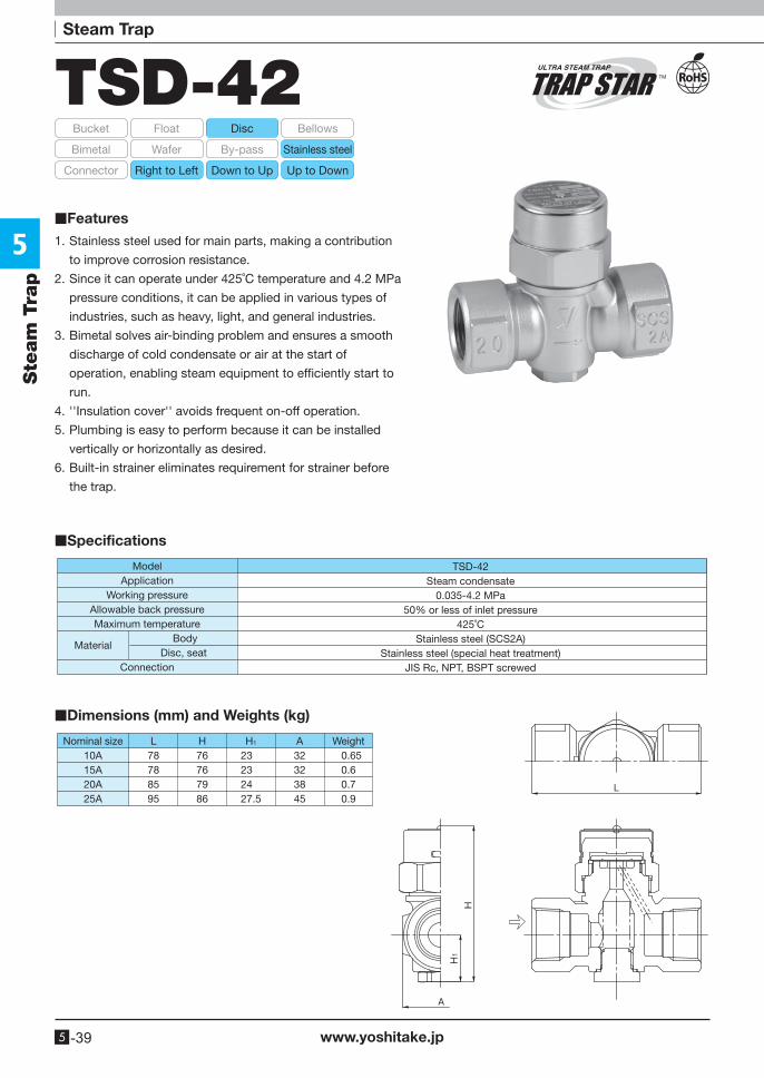
TSD-42
1. Stainless steel used for main parts, making a contribution
to improve corrosion resistance.
2. Since it can operate under 425˚C temperature and 4.2 MPa
pressure conditions, it can be applied in various types of
industries, such as heavy, light, and general industries.
3. Bimetal solves air-binding problem and ensures a smooth
discharge of cold condensate or air at the start of
operation, enabling steam equipment to efficiently start to
run.
4. ''Insulation cover'' avoids frequent on-off operation.
5. Plumbing is easy to perform because it can be installed
vertically or horizontally as desired.
6. Built-in strainer eliminates requirement for strainer before
the trap.
■Specifications
TSD-42Steam condensate
0.035-4.2 MPa50% or less of inlet pressure
425˚CStainless steel (SCS2A)
Stainless steel (special heat treatment)JIS Rc, NPT, BSPT screwed
ModelApplication
Working pressureAllowable back pressureMaximum temperature Body
Disc, seatConnection
Material
■Dimensions (mm) and Weights (kg)
Nominal size H1 WeightH0.650.60.70.9
10A15A20A25A
23232427.5
76767986
32323845
L78788595
A
■Features
5
www.yoshitake.jp 5 -40
Ste
am
Tra
p
TSD-42
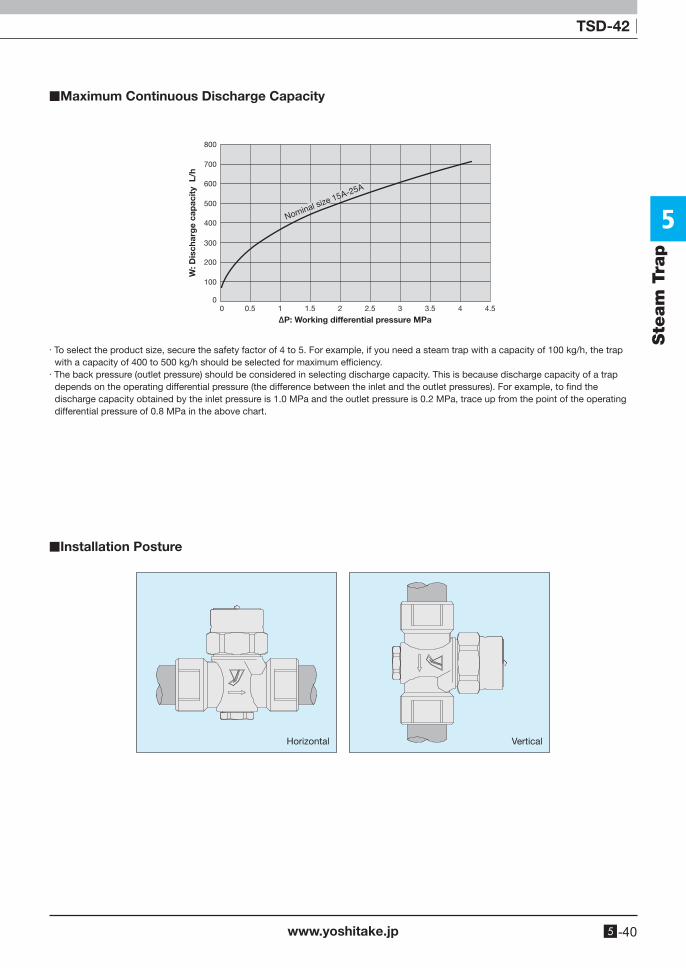
■Maximum Continuous Discharge Capacity
■Installation Posture
· To select the product size, secure the safety factor of 4 to 5. For example, if you need a steam trap with a capacity of 100 kg/h, the trap with a capacity of 400 to 500 kg/h should be selected for maximum efficiency.
· The back pressure (outlet pressure) should be considered in selecting discharge capacity. This is because discharge capacity of a trap depends on the operating differential pressure (the difference between the inlet and the outlet pressures). For example, to find the discharge capacity obtained by the inlet pressure is 1.0 MPa and the outlet pressure is 0.2 MPa, trace up from the point of the operating differential pressure of 0.8 MPa in the above chart.
0
100
200
300
400
500
600
700
800
0.50 1 1.5 2 2.5 3 3.5 4 4.5
W: D
isch
arg
e ca
pac
ity
L/h
∆P: Working differential pressure MPa
Nominal size 15A-25A
Horizontal Vertical