Embed Size (px)
Citation preview
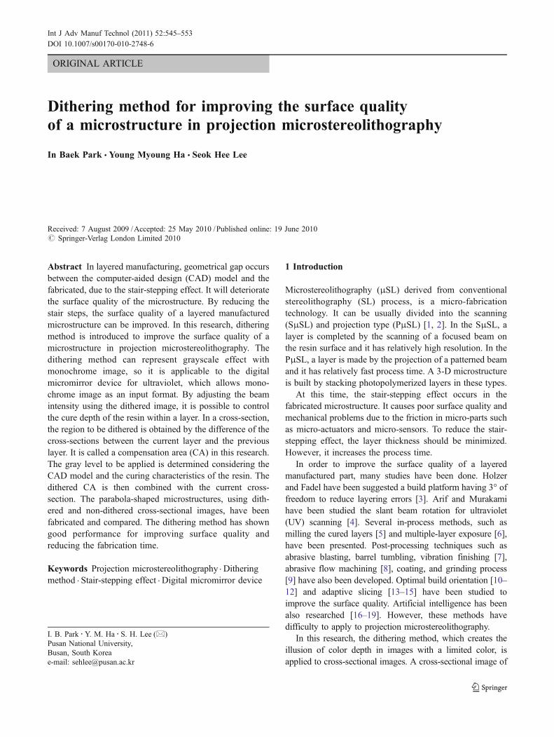
ORIGINAL ARTICLE
Dithering method for improving the surface qualityof a microstructure in projection microstereolithography
In Baek Park & Young Myoung Ha & Seok Hee Lee
Received: 7 August 2009 /Accepted: 25 May 2010 /Published online: 19 June 2010# Springer-Verlag London Limited 2010
Abstract In layered manufacturing, geometrical gap occursbetween the computer-aided design (CAD) model and thefabricated, due to the stair-stepping effect. It will deterioratethe surface quality of the microstructure. By reducing thestair steps, the surface quality of a layered manufacturedmicrostructure can be improved. In this research, ditheringmethod is introduced to improve the surface quality of amicrostructure in projection microstereolithography. Thedithering method can represent grayscale effect withmonochrome image, so it is applicable to the digitalmicromirror device for ultraviolet, which allows mono-chrome image as an input format. By adjusting the beamintensity using the dithered image, it is possible to controlthe cure depth of the resin within a layer. In a cross-section,the region to be dithered is obtained by the difference of thecross-sections between the current layer and the previouslayer. It is called a compensation area (CA) in this research.The gray level to be applied is determined considering theCAD model and the curing characteristics of the resin. Thedithered CA is then combined with the current cross-section. The parabola-shaped microstructures, using dith-ered and non-dithered cross-sectional images, have beenfabricated and compared. The dithering method has showngood performance for improving surface quality andreducing the fabrication time.
Keywords Projection microstereolithography . Ditheringmethod . Stair-stepping effect . Digital micromirror device
1 Introduction
Microstereolithography (μSL) derived from conventionalstereolithography (SL) process, is a micro-fabricationtechnology. It can be usually divided into the scanning(SμSL) and projection type (PμSL) [1, 2]. In the SμSL, alayer is completed by the scanning of a focused beam onthe resin surface and it has relatively high resolution. In thePμSL, a layer is made by the projection of a patterned beamand it has relatively fast process time. A 3-D microstructureis built by stacking photopolymerized layers in these types.
At this time, the stair-stepping effect occurs in thefabricated microstructure. It causes poor surface quality andmechanical problems due to the friction in micro-parts suchas micro-actuators and micro-sensors. To reduce the stair-stepping effect, the layer thickness should be minimized.However, it increases the process time.
In order to improve the surface quality of a layeredmanufactured part, many studies have been done. Holzerand Fadel have been suggested a build platform having 3° offreedom to reduce layering errors [3]. Arif and Murakamihave been studied the slant beam rotation for ultraviolet(UV) scanning [4]. Several in-process methods, such asmilling the cured layers [5] and multiple-layer exposure [6],have been presented. Post-processing techniques such asabrasive blasting, barrel tumbling, vibration finishing [7],abrasive flow machining [8], coating, and grinding process[9] have also been developed. Optimal build orientation [10–12] and adaptive slicing [13–15] have been studied toimprove the surface quality. Artificial intelligence has beenalso researched [16–19]. However, these methods havedifficulty to apply to projection microstereolithography.
In this research, the dithering method, which creates theillusion of color depth in images with a limited color, isapplied to cross-sectional images. A cross-sectional image of
I. B. Park :Y. M. Ha : S. H. Lee (*)Pusan National University,Busan, South Koreae-mail: [email protected]
Int J Adv Manuf Technol (2011) 52:545–553DOI 10.1007/s00170-010-2748-6
1-bit, required image format in the UV-digital micromirrordevice (DMD), can have the grayscale effect due to thedithering method. This method can improve the surface qualityand reduce the fabrication time in the PμSL. The effect isverified through the fabrication of some microstructures.
2 Projection microstereolithography
2.1 Dynamic pattern generator
In the PμSL, a dynamic pattern generator such as liquidcrystal display (LCD) and DMD has been used for shapingthe light [20, 21]. An LCD is usually not suitable for UVdue to the low resolution and transmittance. On the otherhand, a UV-DMD has high resolution and reflectance,superior filling ration, and switching speed [22, 23].
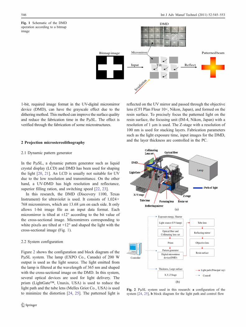
In this research, the DMD (Discovery 1100, TexasInstrument) for ultraviolet is used. It consists of 1,024×768 micromirrors, which are 13.68 μm on each side. It onlyallows 1-bit image file as an input data format. Eachmicromirror is tilted at ±12° according to the bit value ofthe cross-sectional image. Micromirrors corresponding towhite pixels are tilted at +12° and shaped the light with thecross-sectional image (Fig. 1).
2.2 System configuration
Figure 2 shows the configuration and block diagram of thePμSL system. The lamp (EXPO Co., Canada) of 200 Woutput is used as the light source. The light emitted fromthe lamp is filtered at the wavelength of 365 nm and shapedwith the cross-sectional image on the DMD. In this system,several optical devices are used for light delivery. Theprism (LightGate™, Unaxis, USA) is used to reduce thelight path and the tube lens (Melles Griot Co., USA) is usedto minimize the distortion [24, 25]. The patterned light is
reflected on the UV mirror and passed through the objectivelens (CFI Plan Flour 10×, Nikon, Japan), and formed on theresin surface. To precisely focus the patterned light on theresin surface, the focusing unit (IM-4, Nikon, Japan) with aresolution of 1 μm is used. The Z-stage with a resolution of100 nm is used for stacking layers. Fabrication parameterssuch as the light exposure time, input images for the DMD,and the layer thickness are controlled in the PC.
Bitmap image
Input
Patterned beam
ReflectTilt
Micromirror
DMDFig. 1 Schematic of the DMDoperation according to a bitmapimage
(a)
Controller
Thickness, Large surface
Pattern generator
Exposure energy, Shutter
Light source (UV-lamp)
Optical fiber and Collimating lens set
Digital micromirrordevice(DMD)
Prism
Tube lens
Reflecting mirror
X,Y, Z Stage
Light path (Principal ray)
Objective lens
Resin surface
Control
(b)
Fig. 2 PμSL system used in this research: a configuration of thesystem [24, 25], b block diagram for the light path and control flow
546 Int J Adv Manuf Technol (2011) 52:545–553
3 Fabrication method
3.1 Stacking layers
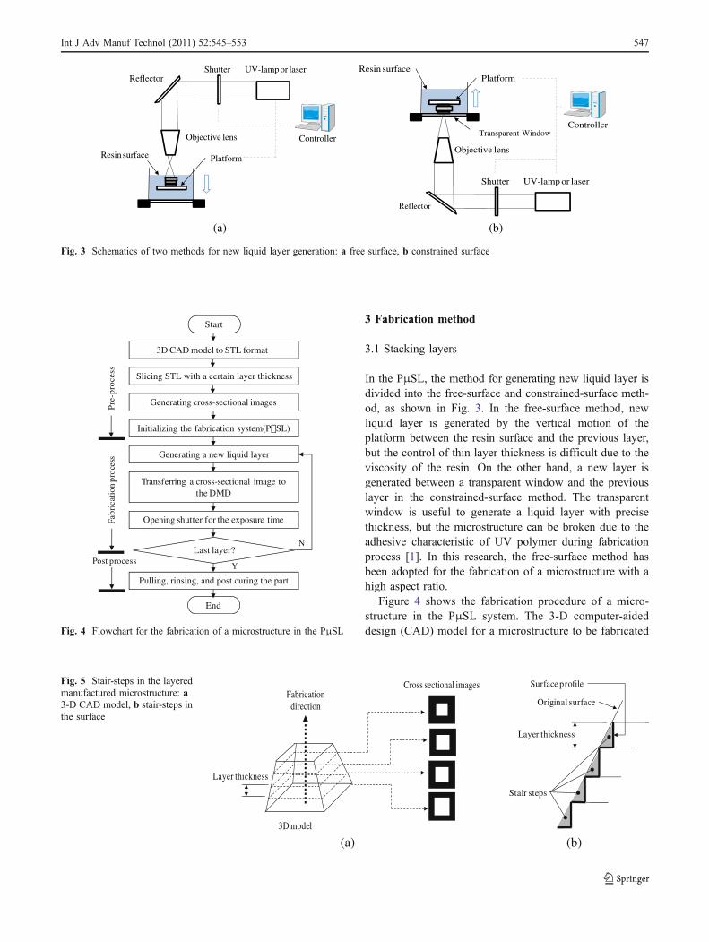
In the PμSL, the method for generating new liquid layer isdivided into the free-surface and constrained-surface meth-od, as shown in Fig. 3. In the free-surface method, newliquid layer is generated by the vertical motion of theplatform between the resin surface and the previous layer,but the control of thin layer thickness is difficult due to theviscosity of the resin. On the other hand, a new layer isgenerated between a transparent window and the previouslayer in the constrained-surface method. The transparentwindow is useful to generate a liquid layer with precisethickness, but the microstructure can be broken due to theadhesive characteristic of UV polymer during fabricationprocess [1]. In this research, the free-surface method hasbeen adopted for the fabrication of a microstructure with ahigh aspect ratio.
Figure 4 shows the fabrication procedure of a micro-structure in the PμSL system. The 3-D computer-aideddesign (CAD) model for a microstructure to be fabricated
Resin surface Platform
Objective lens
UV-lamp or laser
Refractor
Shutter
Controller
ReflectorResin surface
Objective lens
UV-lamp or laser
Platform
Refractor
Shutter
ControllerTransparent Window
Reflector
(a) (b)
Fig. 3 Schematics of two methods for new liquid layer generation: a free surface, b constrained surface
Start
3D CAD model to STL format
Slicing STL with a certain layer thickness
Generating cross-sectional images
Initializing the fabrication system(PµSL)
Generating a new liquid layer
Transferring a cross-sectional image to the DMD
Opening shutter for the exposure time
Last layer?
Pulling, rinsing, and post curing the part
End
N
Y
Pre
-pro
cess
Fabr
icat
ion
proc
ess
Post process
Fig. 4 Flowchart for the fabrication of a microstructure in the PμSL
Layer thickness
Fabricationdirection
Cross sectional images
3D model
Surface profile
Stair steps
Layer thickness
Original surface
(a) (b)
Fig. 5 Stair-steps in the layeredmanufactured microstructure: a3-D CAD model, b stair-steps inthe surface
Int J Adv Manuf Technol (2011) 52:545–553 547
is converted into the STL format. This STL file is thensliced with a certain thickness, which is decided consid-ering the critical exposure energy and light penetrationdepth of the resin. A series of cross-sectional image files,which are 1-bit (white and black) images for the DMD, aregenerated from the slicing data. After all devices are
initialized, the first cross-sectional image of the model isinputted to the DMD. The light emitted from the lightsource is shaped with the cross-sectional image on theDMD. The first layer is then cured by the focused beam onthe resin surface. After refreshing the resin surface as thelayer thickness, the cross-sectional image for the second
1200
220
(a)
Dithered
Dithered
(b)
DitheredDithered
(c)
Dithered
Dithered
(d)
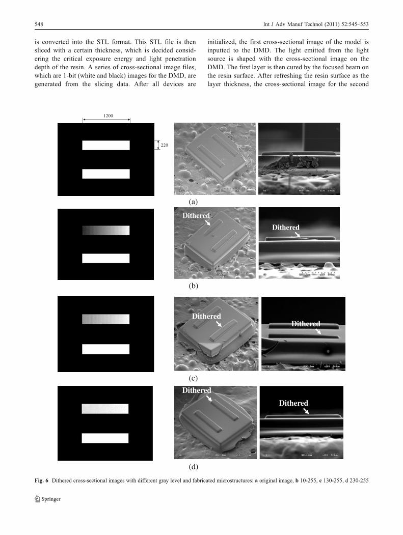
Fig. 6 Dithered cross-sectional images with different gray level and fabricated microstructures: a original image, b 10-255, c 130-255, d 230-255
548 Int J Adv Manuf Technol (2011) 52:545–553
layer is inputted. These steps are repeated until the lastlayer is completed.
3.2 Stair-stepping effect
The stair stepping is the inevitable phenomenon in thelayered manufactured parts [2]. To reduce the stair-steppingeffect in the fabricated microstructure, the thin layerthickness can be applied. However, it can have an adverseeffect on the generation of new liquid layer due to theviscosity of the resin. Therefore, the proper layer thickness
should be acquired from experiments using the Eq. 1 calledthe Beer-Lambert law [1].
Cd ¼ Dp ln Emax=Ecð Þ ð1ÞIn Eq. 1, Cd is the curing depth, Dp is the light
penetration depth, and Ec is the critical exposure energyof the resin, respectively.
Due to the stair-stepping effect, geometrical gap stilloccurs between the original CAD model and the fabricatedmicrostructure regardless of the size of the layer thickness[9], as shown in Fig. 5. In this research, the dithering
800(pixel)
600(
pixe
l)
0 50 100 150 200 2500
4
8
12
16
20
Bea
m In
tens
ity(
mW
/cm
2 )
Gray level
: linear fit
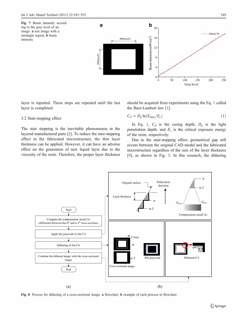
a bFig. 7 Beam intensity accord-ing to the gray level of animage: a test image with arectangle region, b beamintensity
Dithering of the CA
Combine the dithered image with the cross-sectional image
Compute the compensation area(CA)(difference between the nth and n-1th cross-sections)
Apply the grayscale to the CA
Layer thickness
Fabrication direction
Original surface
n-1
nGmax
Gmin
n-1
n
Compensation area(CA)
Dithered CA8bit grayscale
CA(n)
n
n-1
Cross sectional image
Start
End
(a) (b)
Fig. 8 Process for dithering of a cross-sectional image: a flowchart, b example of each process in flowchart
Int J Adv Manuf Technol (2011) 52:545–553 549
unit (µm)
Lt =10µm
unit (mm)
n-1
Cross-section image
n-2
. . .
n
Gmax
Gmin
Boundary curve
(a) (b)
(c)
Detail view
Detail view
Detail view
(d)
(e)
(f)
550 Int J Adv Manuf Technol (2011) 52:545–553
method is applied to each cross-sectional image to reducethe stair steps.
4 Dithering method
4.1 Effect of dithered image
Grayscale is an image, which is composed of shades ofgray, varying from black at the weakest intensity to white atthe strongest [26]. It is recently applied to control theexposure distribution in a photolithography system basedon the LCD [20]. The control of the exposure distribution isalso available to adjust the cure depth, so it is applicable toimprove the surface quality of the layered manufacturedparts. However, a grayscale image is not acceptable to thisDMD, because grayscale cannot be represented with 1-bit.
To display an image with grayscale effect in the DMD, thedithering method is adopted. The dithering is a technique usedin computer graphics to create the illusion of color depth inimages with a limited color palette [27]. Therefore, 1-bitdithered image can show the grayscale effect.
The effect of dithered image has been examined throughcuring experiments. Figure 6a shows the original image.Figure 6b-d show dithered images, which have a varyinggrayscale in the upper rectangle. The grayscale varies from10 to 255, 130 to 255, and 230 to 255, respectively. Thefabrication is done with the same condition for each image:the layer thickness of 50 μm and the exposure energy of16.4 mJ/cm2.
The photocurable resin is composed of 1,6-hexanedioldiacrylate as a monomer and 2,2-dimethoxy-2-phenylace-tophenone of 5 wt.% as a photoinitiator. These chemicalsare mixed with a magnetic stirrer for 3 h in roomtemperature. The resin has a low viscosity of 7 cps, thecritical exposure energy of 3.784 mJ/cm2, and the lightpenetration depth of 440.728 μm. Slope shape can befabricated without stacking layers as shown in Fig. 6.
To examine the beam intensity of dithered image, animage with a rectangle region of 800×600 pixels is used, asshown in Fig. 7a. Grayscale varying from 0 to 255 areapplied to the rectangle region, and each image is dithered.Beam intensity of each dithered image is measured with thebeam profiler (FX66™, Ophir Optronics, Co.). As shown inFig. 7b, the beam intensity is proportional to the gray level.It indicates that the beam intensity can be controlled withdithered image in the PμSL based on the DMD.
4.2 Procedure for dithering of a cross-sectional image
In this research, dithered cross-sectional images are used toreduce the stair-stepping effect. Figure 8 shows theprocedure for dithering of a cross-sectional image. First, across-sectional image of the current layer (nth) is comparedwith that of the previous layer (n-1th), and the compensa-tion area (CA) is obtained by the difference of the twocross-sections. Second, grayscale is applied to the CA. Atthis time, the gray level is determined considering theboundary curve of the 3D CAD model and beam intensityprofile in Fig. 7b. Third, the CA is dithered with Floyd-Steinberg’s error diffusion algorithm [28]. Finally, thedithered CA is combined with the current (nth) cross-sectional image.
5 Microstructure fabrication
5.1 Surface quality improvement
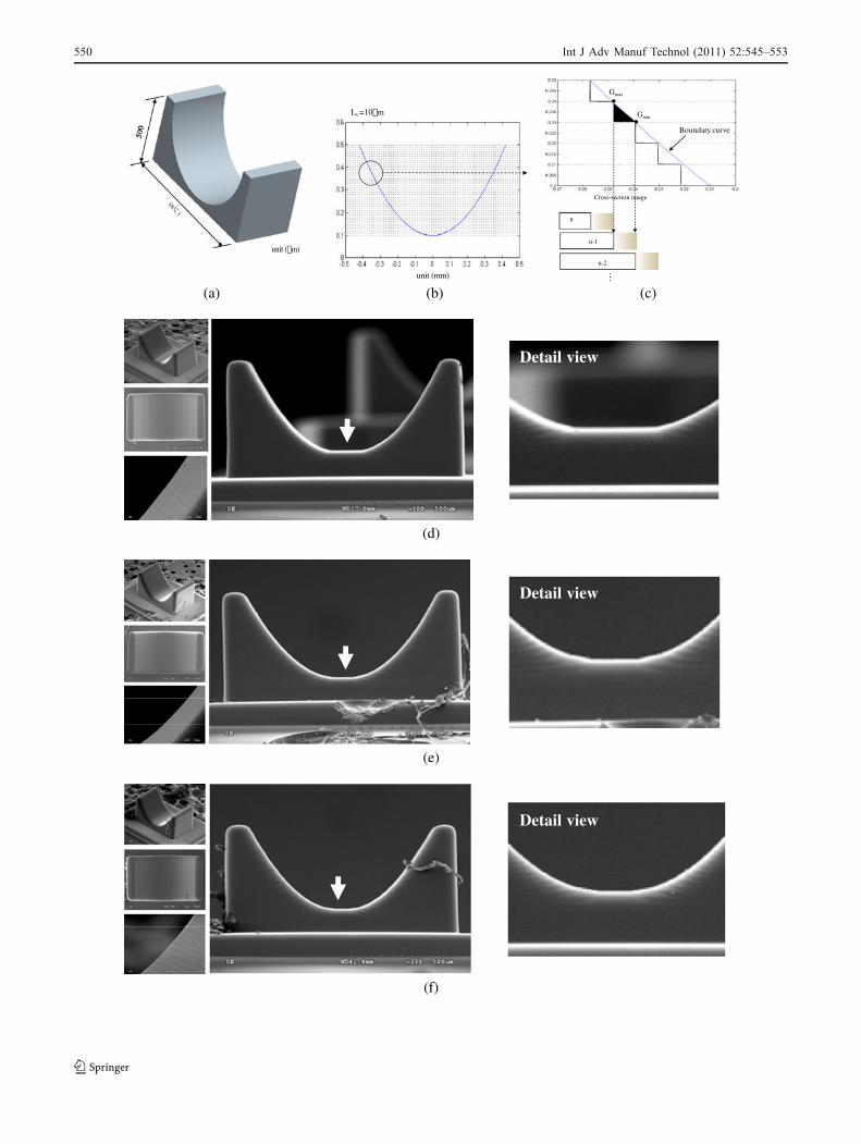
Using dithered cross-sectional images, a parabola-shapedmicrostructure has been fabricated, as shown in Fig. 9. Thefabrication condition is provided in Table 1. 3-D CADmodel is sliced with the thickness of 10 μm, and theapplied gray level varies from 0 (Gmin) to 40. The Gmax of
Table 1 Fabrication conditions for the microstructure in Fig. 9
Original cross-sectional image
Dithered cross-sectional image
Exposure energy (mJ/cm2) 16.4 16.4
Layer thickness (Lt) (μm) 10 10
Total layers 50 50
Gray level - Gmin=0, Gmax=20, 40
Dwell time (sec) 30 30
Total process time (h) 2.5 2.5
Fig. 9 Surface profile improvement using dithered cross-sectionalimages: a 3-D CAD model, b boundary curve and layer thickness ofthe model, c compensation area (CA) to reduce the surface deviation,d fabricated microstructures without CA, e with CA (dithered, Gmax=20), and f with CA (dithered, Gmax=40)
R
Table 2 Fabrication conditions for the microstructure in Fig. 10
Original cross-sectional image
Dithered cross-sectional image
Exposure energy (mJ/cm2) 16.4 16.4
Layer thickness (Lt) (μm) 40 40
Total layers 13 13
Gray level - Gmin=0, Gmax=200
Dwell time (sec) 30 30
Total process time (hr) 0.65 0.65
Int J Adv Manuf Technol (2011) 52:545–553 551
each cross-sectional image was 20 and 40, respectively,considering the surface profile of the CAD model. Dwelltime for generating the new liquid layer is 30 s.
The microstructure, fabricated with original cross-sectional images as shown in Fig. 9d, shows relativelylow stair steps due to thin layer thickness of 10 μm.However, the surface profile of the microstructure deviatesfrom that of CAD model in the bottom of the u-shape,especially. On the other hand, the microstructures, fabri-cated with dithered cross-sectional images such as Fig. 9eand f, show similar surface profile with that of CADmodel. It indicates that the use of dithered cross-sectionalimages can improve the surface quality of a layeredmanufactured microstructure.
5.2 Process time reduction
The main factors to reduce the process time in the PμSL arethe viscosity of the photocurable resin and the number oflayers. The viscosity of the resin has an effect on the dwelltime for generating new liquid layer. The lower the viscosityis, the less process time is required. It can be usuallycontrolled with temperature adjustment of the resin, but thereis a limit to the viscosity control due to the phase or propertiestransition of the resin. On the other hand, the less the numberof layers, the less process time is required. However, it alsoincreases the stair-stepping effect and deteriorates the surfacequality of the fabricated microstructure.
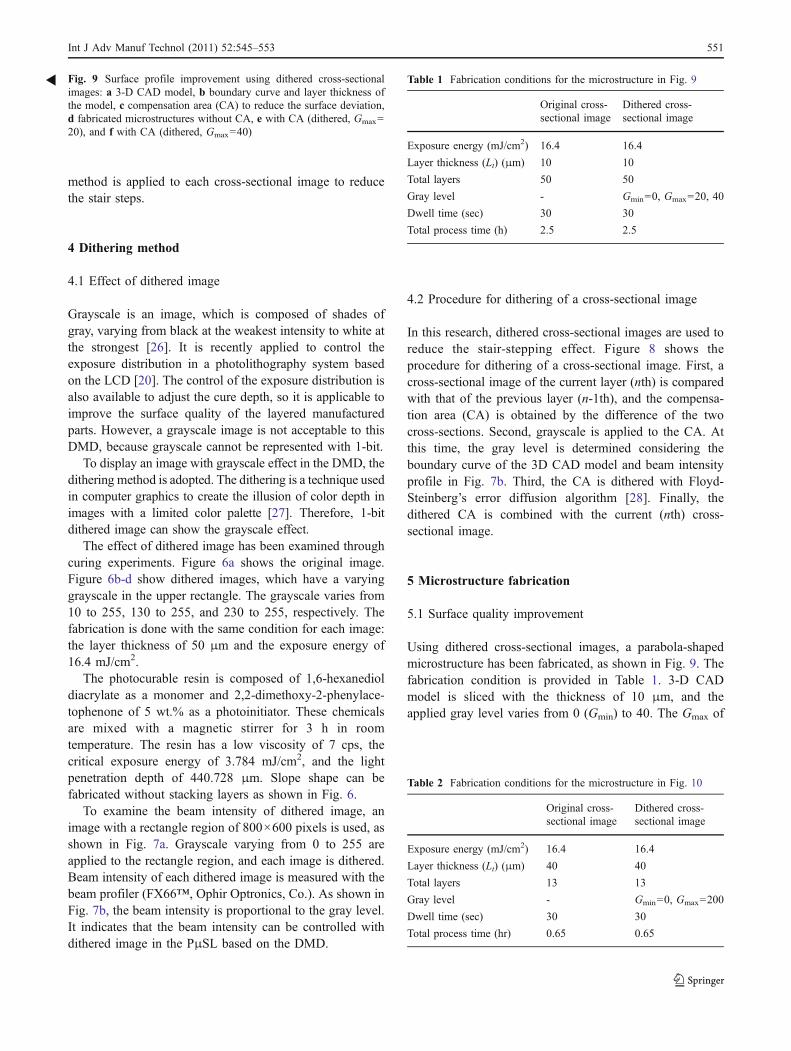
The dithering method can be applied to the fabrication ofa microstructure with the thicker layer thickness. At thistime, the stair-stepping effect can be reduced by the muchdifference of gray level in a cross-section. As shown inTable 2, the layer thickness is thick of four times and totallayers are reduced about one fifth times comparing withthat in Table 1. Consequently, total process time is alsoreduced about one-fifth times while the surface profile isrelatively acceptable, as shown in Fig. 10.
6 Conclusion
In this paper, the dithering method for the effect of grayscalein the projection microstereolithography based on the DMDhas been introduced. Due to the dithering method, the beamintensity distribution can be controlled. Consequently, thestair-stepping effect can be reduced and the surface quality ofthe fabricated microstructure has been improved. Since thedithering method is applied during pre-process, the time forpost-process can be remarkably reduced. Even if the layerthickness increase, the fabricated microstructure has goodsurface quality and the overall process time can be alsoreduced by the dithering method. Our future work includes theapplication for down-facing surface and the establishment ofoptimal dithering algorithm.
This method can control the beam intensity distributionin the system based on a dynamic pattern generator such asLCD and DMD. Therefore, it can be applicable to otherPμSL systems and lithography processes for MEMS.
References
1. Varadan VK, Jiang X, Varadan VV (2001) Microstereo-lithography and other fabrication techniques for 3D MEMS.Wiley, San Francisco, USA
2. Jacobs PF (1992) Rapid prototyping and manufacturing: funda-mentals of stereolithography. SME, Dearborn
3. Holzer F, Fadel G (2002) Design of a 3-degrees of freedom platformfor stereolithography apparatus. Rap Proto J 8(2):100–115
4. Arif KM, Murakami T (2009) Slant beam rotation UV scanning toeliminate stair- steps in stereolithography fabrications. Int J AdvManuf Technol 41(5–6):527–537
5. Ng P, Fang W (1998) Motion compensation for five-axis rapidprototyping system. Rap Proto J 4(2):68–76
6. Murakami T, Yada T, Kobayashi G (2006) Positive direct-maskstereolithography with multi-layer exposure: layered fabricationwith stair step reduction. Vir Phys Proto 1(2):73–81
7. Reeves PE, Cobb RC (1996) Surface roughness investigation ofstereolithography ACES components. Proceedings of the 2nd
Fig. 10 SEM images of fabricated parabola-shaped microstructure: a with original images; b with dithered images (Gmax=200)
552 Int J Adv Manuf Technol (2011) 52:545–553
National Conference on Developments in Rapid Prototyping andTooling, pp. 17–25
8. Williams RE, Melton VL (1998) Abrasive flow finishing ofstereolithography prototypes. Rap Proto J 4(2):56–67
9. Ahn DK, Lee SH (2007) Improving the surface roughness of SLparts using a coating and grinding process. Int J Precis Eng Manuf8(3):14–19
10. Frank D, Fadel G (1995) Expert system-based selection of thepreferred direction of build for rapid prototyping processes. JIntell Manuf 6(5):339–345
11. Cheng W, Fuh JYH, Nee AYC, Wong YS, Loh HT, Miyazawa T(1995) Multi-objective optimization of part-building orientation instereolithography. Rap Proto J 1(4):12–23
12. Ahn DK, Kim HC, Lee SH (2007) Fabrication directionoptimization to minimize post-machining in layered manufactur-ing. Int J Mach Tools Manuf 47(3–4):593–606
13. Hope RL, Roth RN, Jacobs PA (1997) Adaptive slicing withsloping layer surfaces. Rap Proto J 3(3):89–98
14. Tata K, Fadel G, Bagchi A, Aziz N (1998) Efficient slicing forlayered manufacturing. Rap Proto J 4(4):151–167
15. Kumar C, Choudhury AR (2005) Volume deviation in directslicing. Rap Proto J 11(3):174–184
16. Ciurana J, Arias G, Ozel T (2009) Neural network modeling andparticle swarm optimization (PSO) of process parameters inpulsed laser micromachining of hardened AISI H13 steel. MaterManuf Process 24(3):358–368
17. Benardos PG, Vosniakos GC (2003) Predicting surface rough nessin machining: a review. Int J Mach Tool Manu 43(8):833–844
18. Ho SY, Lee KC, Chen SS, Ho SJ (2002) Accurate modeling andprediction of surface roughness by computer vision in turning
operations using an adaptive neuro-fuzzy inference system. Int JMach Tool Manu 42(13):1441–1446
19. Benardos PG, Vosniakos GC (2002) Prediction of surfaceroughness in CNC face milling using neural networks andTaguchi’s design of experiments. Robot CIM-Int Manuf 18(5–6):343–354
20. Hayashi T, Shibata T, Kawashima T, Makino E, Mineta T,Masuzawa T (2008) Photolithography system with liquid crystaldisplay as active gray-tone mask for 3D structuring of photoresist.Sens Actuators A 144(2):381–388
21. Bertsch A, Zissi S, Jézéquel JY, Corbel S, André JC (1997)Microstereolithography using a liquid crystal display as dynamicmask generator. Microsyst Technol 3(2):42–47
22. Douglass MR (1998) Lifetime estimates and unique failuremechanism of the digital micromirror device. IEEE Int ReliabPhys Symp 9–16
23. Dudley D, Duncan W, Slaughter J (2003) Emerging digitalmicromirror device (DMD) applications. SPIE Proc 4985:14–25
24. Park IB, Choi JW, Ha YM, Lee SH (2009) Multiple fabricationsof sacrificial layers to enhance the dimensional accuracy ofmicrostructures in maskless projection microstereolithography. IntJ Precis Eng Manuf 10(1):91–98
25. Ha YM, Choi JW, Lee SH (2008) Mass production of 3-Dmicrostructures using projection microstereolithography. J MechSci Technol 22(3):514–521
26. Johnson S (2006) Stephen Johnson on digital photography.O’Reilly
27. http://en.wikipedia.org/wiki/Dithering28. Floyd RW, Steinberg L (1976) An adaptive algorithm for spatial
grayscale. Proc Soc Inf Disp 17(2):75–77
Int J Adv Manuf Technol (2011) 52:545–553 553