Embed Size (px)
Citation preview

DIY In-Home Anti-Gravity Harness
Midpoint Report
3/3/2017
Khaled Alosaimi
Eileen Baker
Hasan Farman
A.J.Garcia
Noah Oliver
Team 10
Department of Mechanical Engineering
Northern Arizona University
Faculty Advisor: Dr. Kyle Winfree
Instructor: Dr. Sarah Oman

2
Disclaimer This report as prepared by students is part of the university course requirement. Despite the
considerable effort put into the project, it is not the work of licensed engineers and has not undergone the extensive verification that is common in the profession. The information, data, conclusions, and content of this report should not be relied on or utilized without thorough, independent testing and verification. University faculty members may have associated with this project as advisors, sponsors, or course instructors, but as such, they are not responsible for the accuracy of results or conclusions.

3
Acknowledgements The team would like to acknowledge W.L. Gore and Associates for their funding of this capstone
project.

4
Executive Summary In the United States, over 10 million children are living with cerebral palsy, which negatively
affects their ability to move around and socialize. Until the age of 5, these children are immobile, relying on family members to pick them up and facilitate interactions, which can be difficult for parents limited by time and money. Dr. Kyle Winfree, the client for the project and faculty at Northern Arizona University, is attempting to develop an in-home antigravity system that would enable these children to move effectively about a room, thereby increasing their social development. The team formulated a plan for manufacturing of the device, which is currently ahead of schedule. A design of experiments has been put in place so that the optimal movement of the device was assured.

5
Contents Disclaimer ......................................................................................................................................................2
Acknowledgements ........................................................................................................................................3
Executive Summary .......................................................................................................................................4
Background ....................................................................................................................................................6
1.1 Introduction ..........................................................................................................................................6
1.2 Project Description ...............................................................................................................................6
1.3 Original System ...................................................................................................................................6
2 Requirements ..............................................................................................................................................7
2.1 Customer Requirements .......................................................................................................................7
2.2 Engineering Requirements ...................................................................................................................7
2.3 Testing Procedures ...............................................................................................................................8
2.4 Design Links ......................................................................................................................................10
2.5 House of Quality ................................................................................................................................11
3 Existing Designs .......................................................................................................................................11
3.1 Design research ..................................................................................................................................12
3.2 System Level ......................................................................................................................................12
3.2.1 G-Trainer .....................................................................................................................................12
3.2.2 ZeroG ..........................................................................................................................................13
3.2.3 Kickstart ......................................................................................................................................13
3.3 Subsystem Level ................................................................................................................................14
5.1 Rationale for Design Selected ............................................................................................................18
5.2 Design Description .............................................................................................................................20
6 Proposed Design .......................................................................................................................................22
6.1 Implementation Plan ..........................................................................................................................22
6.2 Bill of Materials .................................................................................................................................23
6.3 Spring Schedule .................................................................................................................................23
7.1 Manufacturing ....................................................................................................................................24
7.1.2 Resources ....................................................................................................................................25
7.1.3 Implementation Schedule ............................................................................................................25
7.2 Design of Experiment ........................................................................................................................25
Bibliography ................................................................................................................................................28
Appendix A ..................................................................................................................................................29
Appendix B ..................................................................................................................................................30
Appendix C ..................................................................................................................................................32

6
Background
1.1 Introduction Children with disabilities, especially those with limited mobility, find difficulties later in life with
socialization and cognitive development. A study found that additionally, children less able to interact with their environments have a connection with poor performance on cognitive activities and learning tasks [1]. The same study found that increasing the number of strides a day with disabled toddlers was linked to the greater social association.
Cerebral palsy (CP) is the most common motor disability in children, with every 1 in 323 children born with it [2]. It is a congenital disorder that affects the patient’s posture, muscles, and movement. There are no cures for CP, and the associated treatments are often time and money intensive and can last for the entire lifetime of the child. Every case of CP is unique as each patient experience different physical impairments, including what limbs are affected and to what extent. Children with CP under the age of 5 are often totally restricted in mobility, depending on parents or siblings for all movement or interaction, which negatively affects their developmental outcomes in the future.
This project seeks to formulate a solution to the limited mobility of disabled children by designing a Do-It-Yourself (DIY) anti-gravity balancing system. The sponsor, Dr. Kyle Winfree, is part of the Informatics and Computing division of NAU that aims to create wearable systems that aid everyday life. The project seeks to be DIY to assist parents of disabled children who may be limited by time, money, or training when it comes to improving the socialization of their kids. To fully complete the capstone project, the team will create a device that reduces the body weight of disabled children, allowing them to interact with the world around them, without requiring an advanced degree in engineering or physical therapy for the parents.
1.2 Project Description The project description from the client is as follows:
Children with limited mobility often do not receive the much-needed exposure to socialization to develop cognitively. Existing research shows that enabling young children with self-control of their environment can have meaningful impacts on the long-term outcomes given such impairments as cerebral palsy or muscular dystrophy. One place to start and increase mobility is in the home. Imagine you are a toddler, who isn’t yet able to walk or crawl on your own, and you want to play with a toy on the other side of the room. How the heck is that going to happen if you cannot walk or crawl? The goal of this project will be to design and fabricate a Do-It-Yourself in-home gravity balancing harness system that parents of children with movement disabilities can build with limited resources.
1.3 Original System As this is an entirely new project, there were no original systems that the team improved upon.

7
2 Requirements The client provided the requirements and weighting that were integrated into a House of Quality to facilitate the design process.
2.1 Customer Requirements Conferring with the client and the group resulted in nine governing customer requirements with
weights from 0-10 as seen in the table below.
Table 1. Customer Requirements and Weights
Customer Requirement Weight (x/10)
Safety: Low choking/entanglement risk 10
Ease of Assembly: Avoid machining, complex parts 7
Adjustability: Accommodate different sized children or growth 5
Durability: Materials pass various strength or fatigue tests 7
Size: Is unobtrusive and allows user to interact freely 6
Comfort: Refrain from using coarse/irritating materials 8
Cost: Keep under target cost 7
Workspace Size: Size user has available 6
Aesthetics: Contain multiple colors and child-friendly designs 9
Among the top weighted sponsor requirements were safety, aesthetics, and comfort. The rationale for these requirements resulted from the team's’ concern for creating a product that will positively change lives of children who have Muscular Dystrophy (MD) and various other mobility issues. Part of the success of the design depends on parents of children putting trust into this harness system. This caused the safety weighting to be the most prioritized trait with a rating of a 10. Comfortability and aesthetics were the next highest ratings of nine and eight respectively. The anti-gravity harness system may be used in chunks of time up to four hours, requiring a comfortable fit that does not chafe. Lastly, aesthetics was an addition added by Dr. Winfree from his knowledge of current baby themed products. The team experienced delays in meeting the project’s client due to schedule conflicts, which led to the development of the first six customer requirements being voted on by the team. The addition of cost requirements, aesthetics, and workspace size to Table 1 along with the assigned weights followed the meeting with the client.
2.2 Engineering Requirements The engineering requirements with targets and tolerances are in Table 2 and were formulated
using the customer requirements. The process involved pairing each customer requirement with physical parameters that could be measured or calculated to ensure the customer requirements were met, taking the form of target values and acceptable tolerances. These measurable specifications enabled the team to start prototyping and testing different designs for the anti-gravity system.

8
Table 2. Engineering Requirements
Customer Requirement Correlating Engineering Requirement
Safety: Low choking/entanglement risk • No Sharp Points • No Loose Ropes (Entanglement Risk) • Nontoxic Materials
Ease of Assembly: Avoid machining, complex parts
• No Pinch Points • Less than 20 parts • < 100 Screws and fasteners • Assembly spans two days • No Specialized Parts
Adjustability: Accommodate different sized children or growth
• Socket Sliders • Variety pack for weight bearing parts • Adjustable buckles
Durability: Materials pass various strength or fatigue tests
• Weight of System < 50 pounds
Size: Is unobtrusive and allows user to interact freely
• Fits in 12ftx12ftx12ft Volume Space • Weight of System < 50 pounds
Comfort: Refrain from using coarse/irritating materials
• Elastic Materials • No Pinch Points • No Sharp Points • Padding => .5 inch thick
Cost: Keep under target cost • < 300 Dollars • No Specialized Parts
Workspace Size: Size above user • Fits in 12ftx12ftx12ft Volume Space
Aesthetics: Contain multiple different colors
• Gloss Finish Paints (Non-toxic)
The next step involved addition of the engineering requirements to the HOQ and correlations between these values as well as a ranking of the customer requirements.
2.3 Testing Procedures Determining whether a final product meets engineering requirements required a series of testing procedures to be performed at the end of the year.
1. The parts for the entire system will be weighed using a digital scale from a group member’s house. A member of the team will hold the materials and step on the scale to record the total weight. Then the group member alone will be weighed, and their weight subtracted from the total to ensure the system weight is ideally under 50lbs, but no more than 70lbs max.

9
2. Measuring the storage space and deployed size of the system will involve using a tape measure provided by a member of the group. The storage space will act as the passing test if the measured values are less than 5’x5’x2.5’ with a foot tolerance in each direction. The deployed size must be able to fit in a 12ft3 space with a foot tolerance in each direction.
3. To ensure that the system can handle a 40lb child the team will place a group member’s dumbbells totaling 40lbs in the harness. This requirement will be a pass if the device can hold anywhere from 40-60lbs.
4. The standard of nontoxicity will undergo an evaluation that involves comparing the list of materials in the system to standards set by the EPA. The EPA has lists of chemicals and manufacturing materials considered toxic, and the system will only pass this test if all materials are absent from the list. Additionally, if a toxic material applies in the process, it must be completely covered with a nontoxic material that cannot be removed by the user.
5. Clippers obtained from a team member’s research lab will apply in measuring the padding on the harness as. The padding will be sufficient if it is at least 0.5” thick.
6. No loose ropes due to entanglement risk will undergo evaluation by measuring any loose ends of rope-like materials with a tape measure procured from a team member’s house. The loose ends can be no longer than 3”, and if they are, a zip tie or other constraint must apply in securing them.
7. The total number of parts and screws/fasteners will be counted group members to ensure the parts number less than 20, and screws/fasteners are less than 100.
8. The ropes and other potentially elastic materials will be tested to determine if when force is applied the system deforms more than 10% its original length. A force gauge taken from the physics building will assist in accomplishing this, and a force of 200N applied with the deformation measured with a ruler taken from the chemistry building.
9. The total cost of the product and tools will be measured by totaling the receipts from purchasing all the materials. The product should be ideally under $300 but no more than $400, and the tools less than $100 but no more than $150.
10. The time taken to assemble the entire product will be taken with a stopwatch to ensure it does not take a group member longer than two 8 hours days, with 24 hours as an absolute maximum.
11. A tape measure from a group member’s house will apply in measuring the range of adjustability in the case of adjustable buckles and rope components. All ‘adjustable’ materials must be able to scale at least one inch in both directions to satisfy this test.
12. The criteria of no specialized parts will simply consist of the team evaluating the parts to determine if any were produced at a machine shop and not readily available at a hardware or craft store.
13. No pinch points will be tested by inserting delicate fabric such as silk between two fastenings and seeing if the fabric tears upon applied force.
14. Determining the consideration of no sharp edges will involve qualitative approach by a team member wearing a soft glove while running it over the system. If the glove frays the system still has sharp edges that need smoothing.

10
15. The aesthetics of the design call for the team to use neutral colors so as not to make the system gender specific. Supporting documentation will provide parents with options to make the system more aesthetically pleasing to their specific child.
The team formulated these testing procedures to provide a method of impartially determining the possibility of meeting the engineering requirements in the final design. Should the product fail any one of the testing procedures, a re-engineering of the system is required. These engineering requirements are crucial for the design to conform to customer requirements, which were related using design links.
2.4 Design Links The design links between engineering requirements and real world needs are listed below:
1. The storage space for a harness can come from the closet and other unused space that the user can use to place the system when not in use. The team created a storage space limit of 5x5x2.5 ft. with a slight tolerance of +-1 ft. By incorporating an EZ-up frame into the harness design, it allows the design to be folded into this space easily. When the design is not in use, the team can fit it in a 5x5x2.5 ft. volumes space.
2. The workspace size is volume space the user can have the independent maneuverability to travel while when using the anti-gravity harness. The EZ-up design maximizes this space with a frame having 10 ft.x10ft measurements when unfolded. This is within the 12x12x12 ft. Allowable workspace.
1. The harness system will meet the engineering requirement of no pinch points by using a harness that contains enough stiffness, so it does not allow material to fold on itself beyond certain degrees. To ensure sharp points do not exist in the design, the material of the harness will be soft enough to not snag to the user to cause discomfort. The team will compare the materials ordered for the project to lists of published lists of toxic materials, and substitute any materials that contain harmful toxins with materials that comply with these lists
2. The amount of security the harness will have will increase directly with some contact points the harness contains. The design will most likely contain three contact points to prevent tipping/falling off the user and still provide easy access to the harness
3. Supports which extend from the frame to the user can become a choking hazard to the user if they become loose. The design must contain zero loose ropes and keep the total amount of supports/ropes that extend to the user to a minimal amount (<5) to prevent choking hazards to the user.
4. One of the main project goals for a DIY anti-gravity harness will include minimizing the number of time parents of a child with a disability and/or mobility issues to build our design. The group had accomplished this by limiting the number of parts and fasteners to 20 and 100 respectively. Numbers that exceed these amounts would increase assembly time and cost which are significant customer requirements.
5. Aesthetics in the design are crucial for the design to be successful. The colors picked in the design must be bright and vibrant to appeal to small children. Gloss finish paints will apply in painting the final design to ensure the fulfillment of this engineering requirement.
6. Deformation in the design can cause safety hazards for the user. The frame structure used in the gravity harness design is a product of aluminum alloys and steel. These materials are rigid enough to undergo cyclic loadings of 40 pounds and have axial deformations of under 1x10⁻² inches. The requirement needed to achieve this includes having no elements which are elastic materials that experience high amounts of deformation.
7. Families with children who experience mobility issues and/or have Cerebral Palsy and Muscular Dystrophy is the community that would benefit from group’s anti-gravity harness design. Keeping the final product cost to a minimal is vital to have middle-class families the ability to use our design. In response, the group established a limit of 300 dollars for the final price of the

11
harness with a tolerance of 100 dollars. A number of tools needed for a DIY project must be minimal and widely accessible to customers. A tool budget created covered a limit of 100 dollars. This will allow the use of simple electric drills and screwdrivers when constructing the harness system.
8. Installing the design should take no longer than two full days, as the average working parent is short on time as well as monetary resources.
9. The use of adjustable buckles will allow the sizing of harness along with a growing child. This prevents having to buy an entirely new system when growth spurts happen.
10. 14. The harness design uses parts that can easily undergo fastening. The case is only possible when there are no machined parts for the assembly. Avoiding specialized parts to keeps the cost within the budget and allows most families the ability to put together the project with simple tools found at home.
11. The group’s design will be under the weight requirement of 50 pounds. Tolerancing for this portion is +- 20 pounds which will allow for heavier parts that provide more strength to the design but still keep the overall weight from becoming a hazard.
12. The average weights of children between 1 and five should not exceed 40 pounds. Therefore the system will be designed to support 40 pounds tolerance with an additional 20 pounds.
13. The comfort of the system depends on the padding that will apply in the harness. Half an inch thick padding will help the user to be more comfortable and freely to move around.
14. Using covers for the buckles assures that the user does not get hurt by catching skin between two pressure points.
The team used House of Quality to guide the design process after the engineering needs were related to the client requirements, along with explanations for the selected targets.
2.5 House of Quality The House of Quality (HOQ), found in Appendix A, was organized to present the customer and
engineering requirements, as well as the correlations between the two (Figure 1). The HOQ continues to provide an organized way to begin evaluating any potential designs and existing devices for adherence to the project guidelines. Research on existing devices proved easier with an idea of what characteristics an anti-gravity system needed most. The relative technical importance (RTI) of each quality was ranked using values of one through ten as assigned to specify how strongly an engineering requirement correlate to a customer requirement. Positive numbers denoted a positive relationship while negative numbers signify a negative relationship. The absolute technical importance (ATI) incorporated the relative technical importance and the weights assigned by the client to highlight the most important qualities of the future product.
Assigning targets and tolerances to each of the engineering requirements were a tool for the creation of testing procedures. The HOQ underwent a few minor rewordings after the week of final design selection to conform to client expectations. The revised copy, as well as signed approval from all members and the client, is again accessible in the Appendix A (Figure 1).
3 Existing Designs The rehabilitation industry contains some devices used to assist patients with walking in everyday life, and three of these were selected to help provide a baseline for the project.

12
3.1 Design research The research of existing devices concentrated on journal articles and scientific publications specific to rehabilitation devices using anti-gravity technology.
The process started by finding a variety of different devices from their product pages and continuing the search on Google Scholar. The Google Scholar search produced articles from scientific journals on the various benefits of the systems. The measurement of the articles focused on normal joint angles and forces, metabolic testing with CO2, and surveys used to assess user satisfaction. Sorting the existing devices will then follow based on the benefits observed and if the system would be suitable for children with cerebral palsy to use under the age of five.
From these search results, the team selected three system designs that were appropriate to the project requirements.
3.2 System Level Research focusing on the series of three existing rehabilitation devices (G-Trainer, ZeroG, and
Kickstart) educated the team about existing anti-gravity systems.
3.2.1 G-Trainer The G-Trainer is a rehabilitation device that uses air pressure to unload weight from a patient’s
lower body and enables them to run on a treadmill with reduced impact forces (Figure 2). The G-Trainer sees use in military hospitals, universities, and on professional athletics teams as a way to relearn proper gait and balance without fully loading an injured body part.
Figure 2. G-Trainer Anti-Gravity Treadmill [3]
The integrated treadmill system can support up to an 80 percent reduction in body weight without using a harness that can become uncomfortable or chafe patients [3]. Special shorts are worn to integrate with the airtight enclosure, using air pressure to adjust the amount of loading experienced by the legs. The system is as comfortable on the user as water training but allows the leg swing to mimic above ground locomotion, which contributes to less impairment of normal joint movements. Studies showed that a reduction of 20% body weight did not alter metabolic responses when using the treadmill, proving its ability to maintain fitness during rehabilitation [4].
The main goal of the developing company (Alter-G) is to create a more affordable product to make the G-Trainer a standard in rehabilitative care. There are additional plans to create a similar product for children, to target the population suffering from cerebral palsy or other disorders.

13
3.2.2 ZeroG The ZeroG system is an over ground body-weight system that allows rehabilitation patients to practice daily behaviors while not carrying their entire body weight (Figure 3).
Figure 3. ZeroG Trolley System [5]
The entire system consists of a harness for the patient with support for the groin, hips, chest, and shoulders, a spreader bar to distribute weight, and a trolley connected to an adjustable ceiling track. The trolley tracking system supports the patient without holding them back and is accurate to less than 3 degrees, increasing its ability to prevent falls in the patient [5]. The setup is capable of supporting 400lbs statically and 200 lbs. when moving dynamically [6].
The ZeroG product is more appealing to conventional therapists and users because it allows for a variety of motions to be tested, including sit to stand, climbing stairs, and walking on a curving track. These options have more real life functionality than other rehabilitation setups that depend on lateral movement on a treadmill with only the ability to change speed or incline.
3.2.3 Kickstart Kickstart is a hip-leg exoskeleton that uses tendon and spring technology to enable stroke survivors to learn to walk again. (Figure 4).
Figure 4. Kickstart Powered Assistance [7]
Cadence BioMedical, developer of Kickstart, market the technology as useful to those who have been paralyzed or cannot walk, even years after the incident that left them immobilized. The Exotendon is

14
the core technology behind the device and allows energy to be stored and expended with each step the user takes [7]. The level of assistance can be set by the user or physical therapist to carefully guide the patient to walking on their own as much as possible. Many stroke survivors are afflicted with foot drop, which causes the foot to drag on the ground unless the patient dramatically adjusts their hip positioning with each step. Such a behavior leads to unequal strain on each side of the body, which Kickstart seeks to address by including a foot plate and external ankle joint to assist users with keeping their foot oriented properly. The combination of an external frame with powered assistance makes the Kickstart system extremely accessible for patients with limited mobility.
A restructuring of the system into subsystems followed for the three designs to enable the compartmentalization of the design tasks.
3.3 Subsystem Level To complete the subsystem level designs, the team completed a functional decomposition of the
entire project (Figure 5).
Figure 5. Functional Decomposition of System Level Design
The entire system was broken down into the following subsystems: Harness, Guidance System, and Harness Suspension.
The categorization of the harness was either a full body harness or a simple waist harness. A full body harness was similar to the support seen in the ZeroG system. This full body harness helps reduce the body weight of the user at the groin, hip, chest, and shoulder level to reduce the amount of pressure on a patient needing a high percentage of body weight support. The simple waist harness would benefit users if they can handle walking almost all of their body weight but have troubles with weakness in the legs and can be supported by some outside system. The waist harness would provide the user with less coverage of the body which would be beneficial for some users with increased mobility while the full body harness would provide the necessary protection of the user needing extensive assistance.
The guidance system will be on a guided track system or free motion. The ceiling track system as seen in the ZeroG system will allow the user to follow the path in the direction involved in installing the track system. The free motion guidance system is more of a self-stabilizing harness in which the user is not set to walk on a specific path but can roam while wearing the harness. The way ceiling track benefits

15
the user through increased security in being able to avoid falls that could arise in a free roam system. The upside to unrestricted motion is that the user is more easily able to interact with the environment in any way they please, potentially increasing cognitive development.
The suspension for the harness will be in springs or straps. Springs can provide a reduction in body weight from beneath the user while straps would provide that same reduction but from above the user. Straps provide same similar support but can be more assistive to the user by supporting them entirely.
The subsystem breakdown proved most beneficial to the design process because the different tasks can be divided up in a way that involved all team members’ engineering knowledge. Additionally, a functional model of the system showing all energy flows clarified which steps will require input from the user (Figure 6).
Figure 6. Anti-Gravity Harness Functional Model
For the functional model of the design, the user has some inputs to the system at the starting phase including weight and hand movements. After this occurs, the user is positioned in the harness and will be balanced by outside straps, so they will not overturn over while in the system. The next stage was securing the user so they can be left to perform comfortable movements without upsetting the balance. For this step to be complete, the system must have another person’s hands to secure the user properly within the system, as the children themselves are most likely incapable of performing this task. Upon the completion of all these steps, enabling the movement allows the user to use the system. Once movement comes to an end, exporting the user from the system will then follow with the help of another person.
4 Designs Considered At first, the development of 20 designs used a mixture of a 5-3-5 and gallery concept design techniques. Then, 10 of these designs were under consideration as potential solutions to the problem of building an in-home anti-gravity device. The top four most representative designs are in the figure below (Figures 7-10), with the remainder in the Appendix (Figures 11-16). Those in the Appendix are variations of the four designs in this section, either ceiling mounted or wheeled.

16
Figure 7. Concept A
Concept A was a ceiling track system that allows the user full range of motion across the area the track covers (Figure 7). This system was not the simplest design regarding ease of assembly since the bar in the middle helps the child to move in all directions, requiring heavy modification from basic materials. The harness has two support guidewires on either side to distribute the weight evenly. Unfortunately, the design is for a single room so the child cannot go to another room, limiting the workspace size. The design has a high level of safety based on the secure fastening of the ceiling track. The cost for this design would not be expensive depending on the materials used and can be very durable. It might be difficult to adjust the design for use in other rooms, but adjusting the height for a growing child should prove easy by shortening the strap supports. The design is comfortable for the child with a padded harness that has weight bearing sections.
Figure 8. Concept B
Concept B consisted of a high chair apparatus that employs a harness for the lower extremities rather than a chair suspended from an upper ring at the level of the child’s chest (Figure 8). The whole device is under the guidance of wheels with opportunities for interactive toy placed along the top ring, increasing its aesthetic appeal to children. The device does well under the criteria of being easy to assemble, as the majority of the device is similar to toys already in stores for children learning to walk. Additionally, the relative size of the system makes it very mobile, as well as increasing the range of the child from a single room, to an entire floor of the house as long as entryways are level. Unfortunately, this

17
design is one of the least adjustable for growing children as there are multiple components that would need to be sized up to increase maneuverability. A way to mitigate this would be to create adjustable legs for the chair to raise it above its normal position. The device would have different safety risks than a ceiling system, as the wheels would make it slightly easier to be tipped over, stranding or injuring the child. The durability would depend on the activity level of the child as well as the comfort. The cost would approximately be the same as a ceiling track system, especially since there should be less individual components going into it.
Figure 9. Concept C
This design was a scooter harness system that gives the user the ability to maneuver around the workspace without being limited to the workspace of a single room within a house (Figure 9). This design includes a harness connected to an overhead rod that would suspend the user from the ground while allowing the user to still touch the ground with the removal of the user’s body weight on their legs. The approach allows the user to walk with less body weight weighing on them as they walk. The scooter sub-system of the design is to direct the user to the chosen way to pursue as well as give them additional balance while operating the system. This design gives the user more maneuverability than a track system because track system is free of binding elements that would be within one room of a house. This design is a smaller more mobile design compared to a track system and requires fewer parts to put together overall. The scooter design also has a great adjustability factor that gives the range of heights which allows a wide variety of users to use it no matter their overall size of the user.

18
Figure 10. Concept D
This wheeled system contained a circular base with an extruded circle cut in the middle (Figure 10). This hole leaves open space for the user to have contact with the ground and move around, increasing the available workspace size, though the size of the product is quite a bit larger than some of the other wheeled designs. The thought is to make the device free range motion, but the larger size makes fitting through doorways more difficult. The harness attaches to three rigid supports with elastic straps as the suspension. The user can jump and move similar to bungee jump systems at amusement parks, which may work to enhance the aesthetic appeal to children. The buckles on the straps provide adjustability options for the user to accommodate different heights. This assembly can easily be stored in a closet and should be durable, as long as the construction uses strong materials. The safety might be variable depending on how fast the child moves or the range of motion of the legs, as the inner hole may need to undergo widening. But overall, the device has less of a chance to tip than the other wheeled devices.
With the development of several different styles of anti-gravity systems, the team was able to move on to evaluating the merits of each design. From this, a final product with the highest stats for each customer requirement was selected to begin construction.
5 Design Selected The process of design selection took the top 10 designs down to the three most viable, and finally, the top idea which the team began prototyping.
5.1 Rationale for Design Selected The first step in the design selection process used a Pugh Chart (Table 3) to rank the developed ideas against a Datum concept, as the ceiling track and harness system developed by students at the University of Delaware (Figure 18). The system uses a rectangular PVC system to distribute weight on the harness over a larger area before attaching to a ceiling track.

19
Figure 18. University of Delaware GoBabyGo [8]
The ranking system was qualitative, with a (+) meaning the concept was superior in that category to the datum, a (-) indicated the concept as worse, and an (S) meant the concept had the same expected performance for that criteria.
Table 3. Pugh Chart for Concept Selection
Using the Pugh Chart designs A, B, C, and the Datum emerged as the top concepts. The selections were all wheeled because the team could see the potential of increased safety and maneuverability with a stable, grounded base through the exception of Datum.
These concepts underwent further evaluation using a decision matrix (Table 4), which quantitatively ranked each of the concepts using weighted criteria.

20
Table 4. Decision Matrix for Concept Selection
Concepts Weight A B C Datum
Criterion Safety 0.15 85 12.75 85 12.75 100 15 100 15
Easy to Assemble 0.11 65 7.15 90 9.9 70 7.7 75 8.25 Adjustable 0.08 85 6.8 60 4.8 90 7.2 100 8
Durable 0.11 70 7.7 70 7.7 70 7.7 70 7.7 Size 0.09 100 9 100 9 100 9 70 6.3
Comfort 0.12 80 9.6 80 9.6 90 10.8 90 10.8 Cost 0.14 100 14 86 12.04 85 11.9 85 11.9
Workspace Size 0.09 100 9 100 9 100 9 85 7.65 Aesthetics 0.11 90 9.9 100 11 100 11 80 8.8
Totals 85.9 85.79 89.3 84.4 Relative Rank 2 3 1 4
From the decision matrix, the team selected Concept B as a final design. The harness scooter
performed best in the areas of safety, device size, workspace size, and aesthetics. The case is common for many of the wheeled devices, as the ability to go beyond the room of one house when building interactions with disabled children, ranked highly. The team saw lots of potentials to increase the aesthetic potential of the device, as scooters are already very popular with children. The harness system combined with wheels play a vital role since it allowed taking off weight from the children at the same time as facilitating their movement and stability with the scooter frame. The areas needing the most improvement were ease of assembly and durability, as the design may necessitate slightly rarer parts to fit specifications.
After speaking with the client and watching videos of children with cerebral palsy walking, the team decided to change the final design to one similar to the datum. The jerky walking behavior of the user children exposed safety flaws in a wheeled system which could cause serious damage to the user and the device. A full description of the chosen final design can be found in the following section.
5.2 Design Description The initial sketch of the final design hybridized an overhead track system with a pop-up tent frame to create a more flexible system (Figure 19).

21
Figure 19. Easy Up track system
The final design involved a wheeled track attached to an Easy Up (pop up tent) frame directly above the user. The square Easy Up structure was going to be modified to place weight bearing members running diagonally through the square area. Installing sliders for member movement to the top frame allows the user to move around the area in which the Easy Up covers. Rope supports extend from each rolling slider to a harness system in which involves secure placement of the user. When the user through with the process and the design is not in use, the Easy Up frame folds easily from pushing on all four sides to compact the structure.
As the design is collapsible, it should easily fit in the specified 5’x5’x2.5’ storage space and accommodate a 12’x12’x12’ workspace. This design allowed increased adjustability regarding child size and growth, as a shortening of the height of the suspending ropes is possible for taller individuals. The durability of the materials used for this assembly should adequately support the 40-pound weight average of children between the ages of one and five, even when performing high energy activities. The harness system will provide at least three contact points which distribute the weight even further with a spreader bar attached above. The span of assembly for this design should not exceed two days, as the purchase of the main frame is possible at most sporting goods stores. Lastly, this design will have many aesthetic qualities integrated into its components with bright fabrics, stickers, and paints.
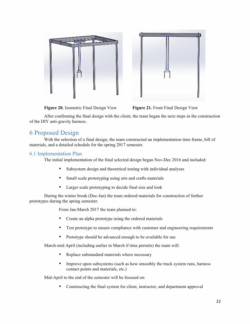
The team produced a Solidworks Rendering of the final design to show further how it will function as an assembly (Figures 20 and 21). After constructing each sub-system of the final design and assembling all pieces into a single unit, some constraint problems needed a solution from the top members. After the addition of mates between parts, the support ropes could not be placed properly to where they would allow the user to use the entire workspace of the system. The fix to this problem will involve cutting the number of rigid supports to two instead of four. Otherwise, the process may require a new material. As the prototyping continues, the materials and shapes of the Solidworks model will undergo changes to reflect the work done.
22
Figure 20. Isometric Final Design View Figure 21. Front Final Design View
After confirming the final design with the client, the team began the next steps in the construction of the DIY anti-gravity harness.
6 Proposed Design With the selection of a final design, the team constructed an implementation time frame, bill of
materials, and a detailed schedule for the spring 2017 semester.
6.1 Implementation Plan The initial implementation of the final selected design began Nov-Dec 2016 and included:
• Subsystem design and theoretical testing with individual analyses
• Small scale prototyping using arts and crafts materials
• Larger scale prototyping to decide final size and look
During the winter break (Dec-Jan) the team ordered materials for construction of further prototypes during the spring semester.
From Jan-March 2017 the team planned to:
• Create an alpha prototype using the ordered materials
• Test prototype to ensure compliance with customer and engineering requirements
• Prototype should be advanced enough to be available for use
March-mid April (including earlier in March if time permits) the team will:
• Replace substandard materials where necessary
• Improve upon subsystems (such as how smoothly the track system runs, harness contact points and materials, etc.)
Mid-April to the end of the semester will be focused on:
• Constructing the final system for client, instructor, and department approval

23
• Compiling supporting documentation for parents to construct the system easily
• Prepare for final presentation
The next step for the team in the implementation plan above was to finish prototyping (proof of concept and industrial) and begin ordering parts for construction.
6.2 Bill of Materials The bill of materials at the end of the fall semester contained the base items necessary for
construction. The harness, ropes, and frame were selected as the best using load analysis for a jumping child, while the sliding components were selected due to their low friction coefficients. As the project is DIY, the availability of these materials was of utmost importance and are available at major retailers around the U.S.
The final design consists of the following parts: Jumper Harness, Nylon Rope, External Slider, Lifting Beam, Ez-up Pyramid Shade, Wrench, Hammer, Power drill, and Screwdriver. The final price for this design was $587.45 at the end of the fall semester. The current BOM can be found in Appendix A (Table 5) and is discussed in terms of current progress in the following chapter.
6.3 Spring Schedule The updated team schedule included the spring semester deadlines and due dates for the completion of the senior capstone project (Figure 22).
Figure 22. Updated Gantt Chart with Tentative ME486 Schedule
The team was behind schedule for a week or two since there were adjustments to the final design after meeting with the client. After making the necessary changes the project is back on schedule and prototyping should proceed as planned for the remainder of the winter semester. All tentative deadlines for the spring 2017 semester were added to the Gantt chart and the team anticipates no problems sticking to his schedule. During the winter break the supplies were ordered for the construction of an alpha prototype during the first section of 2017.

24
7 Implementation After the selection of the final design, the team built a ~60% complete product to stay on track
with midpoint of the semester requirements. This included purchasing materials, assembly, testing, and plans for the remainder of the school year.
7.1 Manufacturing The team placed an emphasis on manufacturing the frame of the project as well as the areas requiring moving parts.
The first stage of manufacturing was assembling the guide rail system, which consisted of two sections of guide rails that could be folded down like a drawbridge when in use. The Easy Up was modified from its original configuration by removing the top tent-like frame which supports the canopy. Then the guide rails were added to existing bolt holes in the Easy Up, which allowed them to be collapsed without needing to be removed from the structure (Figure 22).
Figure 22. Guide Bar Assembly
The guide rails were bolted together in the center when in use and supported with an L shaped section of steel. The ends of the guide rails that extended towards the outside of the frame were bolted down by drilling existing holes in the frame wider and adding eyebolts.
The middle bar since proved to be difficult to construct, as the sideways motion of the frame made it difficult to ascertain proper lengths. The current design has a 10 ft section of a hollow steel tube that spans the length of the Easy Up. Garage door wheels were fixed to the ends by using a rubber stopper with holes drilled through the center. The wheels sit on the track and roll, though there are problems with the rubber being too malleable (Figure 23).
Figure 23. Middle Bar Assembly
The harness system assembly proved much simpler to begin, as the major components could be store bought (harness, spreader bar, nylon rope). The team added the feature of a rock climbing swivel, which would allow the user to turn around when reaching one end of the Easy Up, as opposed to needing to back out. The team realized that the spreader bar purchased from a cargo moving company was over

25
engineered and that future iterations could probably be assembled from cheaper, more lightweight materials. The harness assembly can be seen in Figure 24, with a local crash test dummy placed inside.
Figure 24. Harness Assembly
The team plans to continue fine tuning of the entire device, but important areas of development include increasing the safety of the movement systems and upgrading materials to more industrial grade strength.
7.1.2 Resources The team was informed at the beginning of the semester that the project was entirely funded by
W.L. Gore and Associates, which totalled $1,500. The team has spent $532.13 on the project materials to date, so the remaining budget is $967.87. A detailed breakdown of specific materials, costs, and sources can be found in the BOM (Table 5 and 6, Appendix B).
As part of the project description is that the final product should be affordable, the team made a separate account summary for what the user would expect to pay with the parts so far. At this moment, a user should spend $463.59 on the materials for the device and ~$50 for the tools, depending on what is currently owned by the user.
The next big purchases for the project will include an Easy Up with a sturdier steel frame as well as an improved track system that increases the safety of the device. These purchases will be made within the week to stay on track with the current semester schedule.
7.1.3 Implementation Schedule With the initial planning and building done, the team needed to focus on how to maximize the potential of the final product. A detailed implementation plan can be found in Appendix D (Table 7).
The project is currently on schedule to complete a final product and presentation by the end of the semester. The advisor and client have both expressed satisfaction with the current state of the system.
7.2 Design of Experiment The design of experiment (DOE) was performed to maximize the ease of movement of the proposed final design.
After conferring with the client, the team decided to test variations of design that would increase the ability of the user to move large distances with the minimum amount of effort. The variables tested involved the middle bar of the design, including the wheels on the ends connecting to the track and the construction of the sliding bar than moves along the middle bar. The material of the wheels were changed

26
(nylon vs. stainless steel) to see if different coefficients of friction make for a smoother motion. The second variable affected the sliding bar that currently consists of a PVC section where the team was interested to see if changing the length of the section (2ft vs 4ft) would distribute the weight differently. The last variable tested was the use of bearings to facilitate the movement of the PVC section or just using the current sliding bar without any changes.
To test these effects on the system, the Easy Up was assembled to the most recent configuration with the resident crash test dummy placed inside. Each possible combination of wheel material, presence of bearings, and length of PVC sliding bar was tested and assessed on total distance traveled, both forwards and laterally. The harness was moved to the “back” of the Easy Up and given a push by one group member forward. The distance traveled forwards was measured with a measuring tape and the harness was then moved laterally to the extreme side. The system was given another uniform push to the side by the same group member and the distance traveled to the side was measured. The two distances were added together for a total distance traveled, with a higher value being desired (Figure 8). The total process was repeated twice, with the order of tests randomized, to ensure precise results.
Figure 8. Design of Experiments
The results of the DOE showed that the variables of wheel material and the material of the sliding bar were the most impactful determinants of total distance traveled because the effects were farthest away from 0 (12.75 and -10.625 respectively). Specifically, the steel wheels and the PVC alone were favored for maximizing the distance traveled. The length of the PVC section did not seem to affect how far the device was able to move. However, the effects were not statistically significant results as none of the results were bigger than three times the standard deviation of 8.33.
The team found it surprising that the PVC alone moved better that with bearings, but attributed it to faulty connection points between the PVC and the bearings that was dragging along the middle bar. In a test after the DOE the team found that the harness assembly attached to the bearings alone could travel the entire length of the middle bar with ease. The focus of the next week will be to securely attach the PVC to the bearings so that the device has the benefits of weight distribution and low friction movement.

27
The steel wheels will continue to be used in the device, though the team would like to find a way to make them quieter, like the nylon ones. As the length of the PVC did not seem to make a difference the device will continue to employ the 2ft section, as it allows the user more freedom of lateral movement.
By exploring ease of movement options using a DOE, the team could determine which variables were contributors to later prototype success. Further testing with bearings should dictate whether the DOE results were due to incorrect coupling between sections or a real disadvantage to utilizing bearings.

28
Bibliography
[1] S. Logan, M. Schreiber, M. Lobo, B. Pritchard, L. George and J. Galloway, "Real-World Performance: Physical Activity, Play, and Object-Related Behaviors of Toddlers with and Without Disabilities," Pediatric Physical Therapy, vol. 27, pp. 433-441, 2015.
[2]"Data and Statistics | Cerebral Palsy | NCBDDD | CDC", Cdc.gov, 2016. [Online]. Available: http://www.cdc.gov/ncbddd/cp/data.html. [Accessed: 29- Sep- 2016].
[3] "‘Anti-Gravity’ Treadmills Speed Rehabilitation." Spinoff.Nasa.Gov, 2009, https://spinoff.nasa.gov/Spinoff2009/hm_5.html.
[4] C. R. Pedlar, R. Burden, J. Hill, and G. P. Whyte, “Physiological Responses To Simulated Anti-gravity During Treadmill Running,” Medicine & Science in Sports & Exercise, vol. 43, no. Suppl 1, pp. 779–780, 2011.
[5] J. Hidler, D. Brennan, i. Black, D. Nichols, K. Brady and T. Nef, "ZeroG: Overground gait and balance training system," The Journal of Rehabilitation Research and Development, vol. 48, no. 4, p. 287, 2011.
[6]"ZeroG Product Technical Specifications," Aretech, LLC, 2016. [Online]. Available: http://www.aretechllc.com/products/zerog-gait-and-balance/#product-tech-specs.
[7]"Kickstart - Recover to Walking," Kickstart, 2016. [Online]. Available: http://www.cadencebiomedical.com/kickstart-product. [Accessed: 30- Sep- 2016].
[8] “Force Fields,” GoBabyGo. [Online]. Available: http://sites.udel.edu/gobabygo/.
[9] Johnny Jump Up Harness. [Online]. Available: https://www.walmart.com/ip/Evenflo-Johnny-Jump-Up-Bumbly/22236459
[10] H. D. P. Authority, "Everbilt 3/8 in. X 1 ft. Navy Double Braid Nylon rope-70416 - the Home Depot," The Home Depot, 2000. [Online]. Available: http://www.homedepot.com/p/Everbilt-3-8-in-x-1-ft-Navy-Double-Braid-Nylon-Rope-70416/206189264.
[11] Constantino, "Build your professional DIY video Slider," Photo CS, 2012. [Online]. Available: https://photoscs.wordpress.com/2012/02/28/build-professional-diy-video-slider/.
[12] http://yatesgear.com/es/heavy-rescue-spreader-bar
[13] 2016 A, "EZ up pyramid 10 x 10 new colors and features - FREE SHIPPING," 2013. [Online]. Available: http://www.ezup4less.com/acatalog/Easy Up-Pyramid-10-x-10-New-Colors-and-Features-313.html?gclid=CjwKEAiA6rrBBRDsrLGM4uTPkWASJADnWZQ4RpZF4gObQzrEyuvQ7x1GavWraaVREZG6PMBRAXXrmhoCpWzw_wcB.

29
Appendix A The House of Quality was updated the week of 11/14 and approved by all team members and the client (Figure 1).

30
Appendix B Table 5. Bill of Materials
Component Image Cost Seller
Jumper Harness
$16
Walmart.com
[9]
Nylon(2)
$17
HomeDepot.com
[10]
Spreader Bar
$75
Officerstore.com
[12]
Easy Up Pyramid
Shade
$219
Ezup4less.com
[13]
Aluminum Track
$0.01
HomeDepot.com
[14]
Guide Rail(2)
$45
HomeDepot.com
[15]
Garage Rollers
$5
HomeDepot.com
[16]
Galvanized Steel
Chain-Link
$12
Lowe’s.com
[17]

31
Stainless Steel
Eye Bolt
$2
HomeDepot.com
[18]
SuperSlide 4 ft. Closet Hanging
Rod
$6
HomeDepot.com
[19]
SuperSlide 8 ft.
White Closet Rod
$12
HomeDepot.com
[20]
Coarse Zinc-
Plated Steel Flat-Head Phillips
Machine Screws(2)
$1
HomeDepot.com
[21]
Zinc-Plated
Punched Angle(2)
$20
HomeDepot.com
[22]
PVC DWV Plain
End Pipe
$8
HomeDepot.com
[23]
Plain Steel Flat
Bar
$6
HomeDepot.com
[24]
Ball Bushing Linear Motion Bearings(2)
$20
VXB.com [25]

32
Table 6. Tools
Component Image Cost Seller
Wrench
$8
Target.com [26]
Hammer
$6
Zoro.com [27]
Power drill
$25
Walmart.com [28]
Screwdriver
$26
Toolnut.com [29]
Appendix C The following designs are a continuation of section 4, and all figures are variations of those seen above.
Figure 11. Concept E
The first concept was an adapted walker such as those used by the elderly, with adjustments to make it more child-friendly (Figure 11). There is a seat harness that holds the user in place and gains its support from the straps attaching to the frame. The ability to move effortlessly is the most important need supplied by this product, as it maximizes the workspace while limiting the size of the product. This is a comfortable support system, as an increased number of straps distribute the weight evenly. As a wheeled system concept 1 has a high degree of safety, with wheels that can be locked to limit movement of the child if the parent deems it necessary. It has even tabs for adjusting to the required arm size, whether the

33
child wants to push with legs and want additional stability or to free the arms to interact with the world. The cost and durability of this design are dependent on the quality of materials used, with cheaper versions potentially including PVC pipe and wheelchair wheels. The aesthetics of the system is high, as the number of surfaces the child can touch is high, and each could have colorful objects or images.
Figure 12. Concept F
Concept F was a ceiling track system that allows the child to go everywhere in the room, and potentially gain momentum going in circles (Figure 12). The harness has four guidewires that help to make the weight distributed, potentially increasing the comfort and safety of this system over other options. The design has parts less than 20 parts, as the circular track should contribute to the easing of assembly as long as the circle shape is pre-formed. The motion of the system involves control, as the frame limits the workspace of the child, even though the size of the product is on the smaller size. The aesthetics are up to the builder and child, though the appeal of being able to move at higher speeds may appeal to some users. The safety could also be a little questionable regarding the child vomiting if they manage to build up enough speed turning in circles.
Figure 13. Concept H
Concept H was a variation of a ceiling track system, without being limited to a single room (Figure 13). The frame supports a harness on the child with straps while preserving a free motion

34
guidance system with the wheels on the bottom. This concept has the same safety as a ceiling track system but only if designed appropriately, which would affect the ease of assembly. The adjustability of the device would also be difficult but is possible to accomplish by creating an initially taller frame and different lengths of straps. The workspace size of the child would be increased to any room of the house as long as the device fit through the door, but would probably be a little less durable due to bumping into objects. The comfort and aesthetics of the design are entirely reliant on the options of padding and paint as chosen by the parent of the child. The cost would hopefully be close to that of a ceiling track system, but such a hybrid system would most likely require a few prototypes before being completely safe.
Figure 14. Concept I
This design was a variation of a ceiling track system in which the ceiling track can be removed from the bolted down railing system and moved to another track system to another room within a house which can maximize the workspace for the user by not limiting them to one room (Figure 14). The way this system would work would be a harness would be attached to sliders on a track system that would allow the user to maneuver the room the system is set up in a while in the harness to reduce body weight experienced on the user's legs. This design adds more workspace possibility for the user which can be beneficial since the user can utilize the system in different settings instead of being limited to a one room track system. This design involves adjustability at all corners of the track system and can in some cases be more durable than a mobile design because it does not have the chance of being crashed into a wall by a user. This design also has a higher safety rating than a mobile design since it is a track system and is not being moved around constantly like a mobile design.

35
Figure 15. Concept J
This track design was mounted in the ceiling space in a room and provides four outer-extreme points of destination the user can travel (Figure 15). A bearing assembly with wheels allows movement along the track. The harness subsystem is secured with two supporting straps to prevent the child from tipping over. The track design is extremely durable, and the harness is easily adjustable for different sized children. The system assembly has limited mobility and will be difficult to move into other rooms. The design does not have the ability to be stored separate from its location of use, increasing its size while not maximizing all available workspace. The aesthetics and safety of this product are similar to other ceiling mounted systems, with all aspects being fairly safe, though potentially a bit restrictive. The system will be as comfortable based on the design of the harness, with increased padding and weight support being a top priority.
Figure 16. Concept M
36
This design used a combination of ceiling tracks, retractable pulleys, and a looser harness system to adapt the ceiling mounted designs seen so far (Figure 16). The user can move along two ways in the x-direction. The user has support from two directions with supports extending from the retractable rope feeds, thereby increasing the safety and support in those directions. The track system uses small bearings that glide along the length of the track giving the user mobility. Tension forces in the rope can be adjusted/calibrated to keep the user balanced in equilibrium to prevent tipping, but an additional rope in the back may need to be added to prevent the child from flipping. The cost of this design would be higher than all previous designs discussed as the retractable rope feeds would be difficult to design. The complexity of assembly will cause a high risk of malfunction with inexperienced builders and may prove to be too challenging for a DIY project.
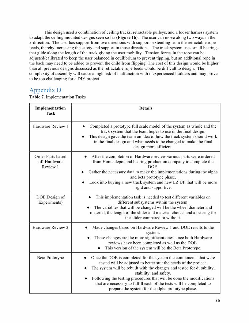
Appendix D Table 7. Implementation Tasks
Implementation Task
Details
Hardware Review 1 ● Completed a prototype full scale model of the system as whole and the track system that the team hopes to use in the final design.
● This design gave the team an idea of how the track system should work in the final design and what needs to be changed to make the final
design more efficient.
Order Parts based off Hardware
Review 1
● After the completion of Hardware review various parts were ordered from Home depot and bearing production company to complete the
DOE. ● Gather the necessary data to make the implementations during the alpha
and beta prototype phase. ● Look into buying a new track system and new EZ UP that will be more
rigid and supportive.
DOE(Design of Experiments)
● This implementation task is needed to test different variables on different subsystems within the system.
● The variables that will be changed will be the wheel diameter and material, the length of the slider and material choice, and a bearing for
the slider compared to without.
Hardware Review 2 ● Made changes based on Hardware Review 1 and DOE results to the system.
● These changes are the more significant ones since both Hardware reviews have been completed as well as the DOE.
● This version of the system will be the Beta Prototype.
Beta Prototype ● Once the DOE is completed for the system the components that were tested will be adjusted to better suit the needs of the project.
● The system will be rebuilt with the changes and tested for durability, stability, and safety.
● Following the testing procedures that will be done the modifications that are necessary to fulfill each of the tests will be completed to
prepare the system for the alpha prototype phase.

37
Alpha Prototype/Final Testing Phase
● This prototype will include all of the correct subsystems that will be involved in the final design.
● Once this prototype is completed the team will make the last adjustments to the overall system to prepare for the final design and
UGRADS presentation.