Embed Size (px)
Citation preview

1
Double-Electrode GMAW Process and Control
Kehai Li, Jinsong Chen and YuMing Zhang*
Center for Manufacturing and
Department of Electrical and Computer Engineering
University of Kentucky, Lexington, KY 40506
Abstract
Double-Electrode Gas Metal Arc Welding, referred to as DE-GMAW, is a novel process
which decouples the melting current into base metal current and bypass current by adding
a bypass torch to a conventional GMAW system to establish a bypass arc. This makes it
possible to increase the melting current while the base metal current still be controlled at
a desired level. Experiments have been done to find the conditions which can assure a
stable bypass arc be established/maintained between the welding wire and the bypass
torch. To control the base metal current at the desired level, a group of power resistors is
added in the bypass loop. The resistance of the power resistor group is adjusted real-time
by changing the combination of the resistors and the change in the resistance results in a
change in the bypass current thus a change in the base metal current. A model has been
developed to correlate the change of the resistance needed to achieve the desired base
metal current to the deviation of the base metal current from its desired level.
* Corresponding author, email: [email protected]

2
Experiments demonstrated that the developed control system can adjust the bypass
current in a large range to maintain the base metal current at the desired levels.
Keywords: Double-Electrode, GMAW, Base Metal Current, Control, Heat Input,
Welding Productivity.
1. Introduction
Gas Metal Arc Welding (GMAW, also known as MIG) is a major process for metals
joining. Conventional GMAW is normally used in the direct current reverse polarity
(DCEP), in which the wire is connected to the positive terminal of the power source and
the power source operates in the constant voltage (CV) mode. The reverse polarity
contributes to a stable arc, uniform metal transfer and greater penetration. A CV power
source can adjust the welding current such that the wire melting rate is equal to the given
wire feed speed, inherent the welding voltage or the arc length is maintained constant.
For automatic and semi-automatic welding, the productivity is mostly determined by the
travel speed provided that the welding performance criterion is met, for example, the
cross-section area of the weld bead is not changed with the travel speed. Obviously, a
faster travel speed requires a larger wire melting rate such that the melted metal is enough
to form a longer weld bead in a unit time. Based on the work by Waszink and Heuvel
(Ref. 1), the melting rate can be calculated in the following formula if the metal transfer
is in spray mode, i.e., the melting current is greater than 250amps for mild steels.

3
213 65.1 10 2.2 10I Lm I
S− −= × + × (1)
where m [kg/s] is the melting rate, I [A]is the total melting current, L [m] is the wire
extension, and S [ 2m ] is the cross-section area of the wire. That means the melting
current must be increased in order to increase the melting rate. Unfortunately, the melting
current in conventional GMAW is the same as the base metal current. Thus, a larger
melting current not only melts the wire faster, but also increase the based metal heat input
contributing to enlarge the weld pool, residual stress, and distortion. This fundamental
characteristic of conventional GMAW makes it difficult to increase the deposition rate
without imposing excessive heat to the base metal.
While Tandem GMAW (Refs. 2, 3), T.I.M.E (Refs. 4, 5), and Variable-Polarity GMAW
(Refs. 6-8) have successfully increased the melting rate to certain degrees without
changing this fundamental characteristic of conventional GMAW, the double-electrode
GMAW process (Ref. 9) proposes a way to change this fundamental characteristic so that
the melting rate can be increased relatively greatly and freely. In a previous preliminary
study (Ref. 9), this change was realized by adding a plasma torch and a second power
supply to a conventional GMAW system. In this study, the DE-GMAW process is
implemented without the second power supply. In addition, the plasma torch is replaced
by a gas tungsten arc welding torch which is more durable and cost effective.

4
2. Principle of DE-GMAW
A DE-GMAW system (Fig. 1) is formed in this study by adding a non-consumable
tungsten electrode to decouple the melting current into base metal current and bypass
current:
bm bpI I I= + (2)
where I [A] is the total current or melting current, bmI [A] is the base metal current,
bpI [A] is the bypass current. As can be seen in Fig. 1, the bypass current flows back to
the power source through the bypass torch without going through the base metal. As a
result, the base metal current is no longer the same as the melting current and the
fundamental characteristic in conventional GMAW no longer applies. On the other hand,
as will be illustrated later, the total melting current is still determined by the wire feed
speed and welding voltage as in convention GMAW. Hence, the bypass arc can change
and reduce the base metal current without changing the total melting current.
The bypass loop in Fig. 1 includes an adjustable resistor. When this system is used, the
user can choose the wire feed speed based on the deposition rate desired. The total
current which melts the wire will be dictated by the wire feed speed and the arc voltage
setting. When the resistance of the adjustable resistor is zero, the majority of the melting
current would intend to flow through the bypass loop because the tungsten is easier to
emit electrons than the work piece. To control the base metal current at the desire level,

5
the resistance of the adjustable resistor is feedback adjusted using a current sensor which
measures the base metal current (Fig. 1).
It is apparent that the heat absorbed by the tungsten and the power resistor is wasted.
However, this part of heat would be applied on the base metal if the bypass loop is not
applied as in conventional GMAW so that the base metal is over heated. That is, in
conventional GMAW, this part of heat is not only wasted but also produces harms to the
process.
3. Process Stability
The presence of the bypass arc is the fundamental characteristic of the DE-GMAW
process. A stable bypass arc assures the DE-GMAW function. Hence, the behavior and
stability of the bypass arc must be studied and understood. For the novel DE-GMAW
system demonstrated in Fig. 1, the behavior and stability of the bypass arc are determined
by several parameters discussed below.
3.1. Bypass Electrode
In the proposed DE-GMAW process, there are two cathodes: one is the workpiece, and
the other is the bypass electrode, which forms the bypass arc with the welding wire. The
bypass electrode must be qualified for two criteria: high melting point and good electrical
conductivity. Two materials have been tested during the implementation: water-cooled

6
copper and tungsten. But the former appears too ‘cold’ to ignite the bypass arc even
though it is very close to the GMAW arc. It was found the tungsten electrode is a very
active bypass electrode, as it is used in GTAW. Thus, a commercial GTAW torch is used
to hold the tungsten electrode and at the same time to provide the shielding gas for the
bypass electrode. With a tungsten bypass electrode, the arc stability is significantly
improved.
3.2. Shielding Gas for Bypass Electrode
To protect the tungsten electrode from oxidizing, pure argon is recommended for
shielding gas. Because of the action of electric field and arc radiation, the argon will be
ionized. This ionized argon atmosphere further improves the stability of the bypass arc. If
the bypass current is higher than 150amps, a water-cooling system is required to protect
the bypass torch.
3.3. Tungsten to Welding Wire Distance
The horizontal distance from the tungsten end to the welding wire end, 3d in Fig. 2, is
also an important parameter to obtain a stable DE-GMAW process. It is found that a
distance in the range from 2mm to 5mm is optimal for achieving a stable bypass arc. A
larger 3d will tend to increase the difficulty to start the bypass arc. A smaller 3d will
tend to expedite the burn-off of the tungsten electrode.

7
3.4. Tungsten to Workpiece Distance
The distance between the tungsten electrode and the workpiece, 2d in Fig. 2, can not be
too large in order to start the bypass arc. In DE-GMAW process, the GMAW torch feeds
in the welding wire to strike the main arc between the welding wire and the workpiece.
The bypass arc is then ignited via the main arc. To assure the bypass arc to be ignited, the
tungsten electrode has to be close enough to the main arc. Experiments revealed that the
optimal value of 2d is about 6mm.
3.5. Contact Tube to Workpiece Distance (CTWD)
The contact tube to workpiece distance 1d as shown in Fig. 2 is also important for
achieving a stable bypass arc. A relatively larger 1d is required in order to provide the
space for the bypass torch in the current implementation. Experimental observation
showed that the optimal distance 1d is approximately 20mm. And the welding voltage for
the GMAW power source is pre-set around 28volts – 35volts correspondingly.
3.6. Angle between Tungsten and Welding Wire
Another parameter that determines the behavior and stability of the bypass arc is the
angle θ between the tungsten and the welding wire, illustrated in Fig. 2. The GMAW
torch is placed at a normal work position. The angle θ can be adjusted by changing the
position of the bypass torch. Because the tungsten electrode needs to point to the weld
8
pool, the angle θ can not be too large. Considering the size of the bypass torch and the
distance 1d , the angle θ is limited to around 60 degrees.
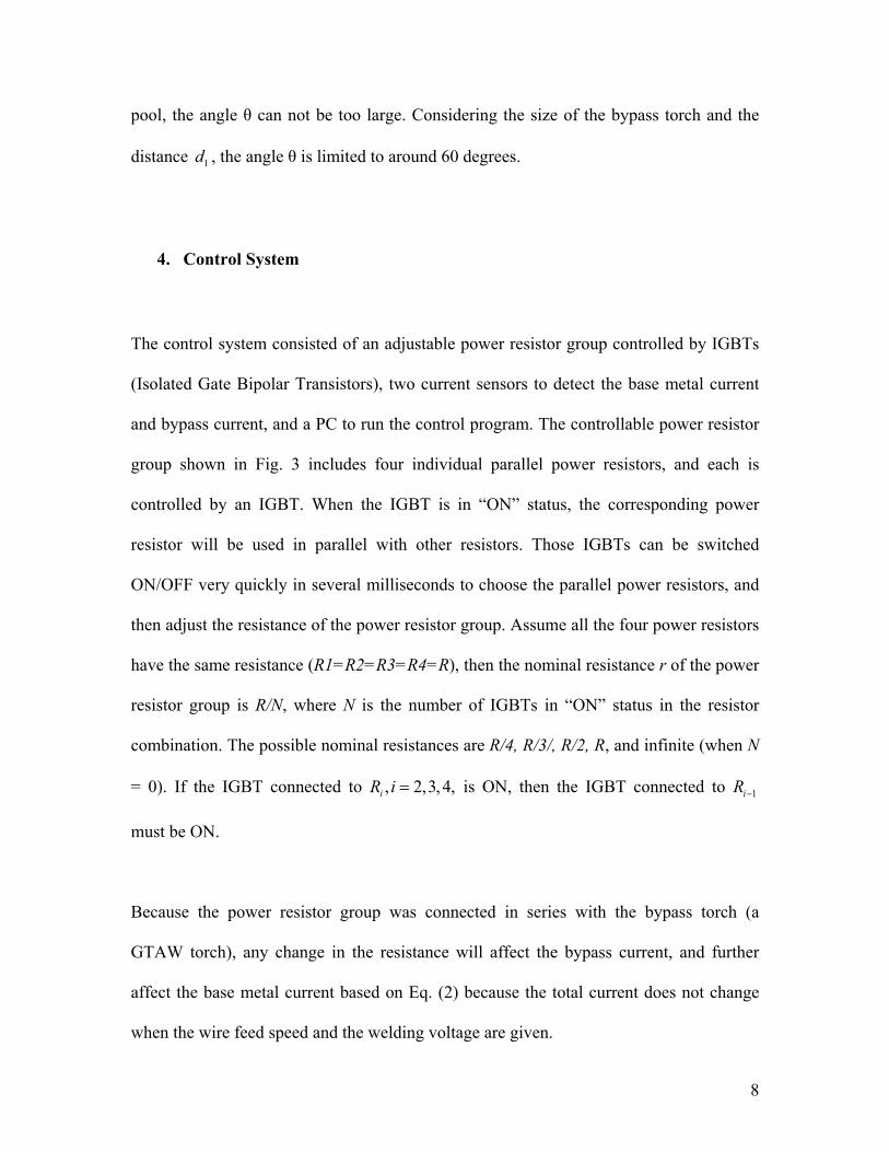
4. Control System
The control system consisted of an adjustable power resistor group controlled by IGBTs
(Isolated Gate Bipolar Transistors), two current sensors to detect the base metal current
and bypass current, and a PC to run the control program. The controllable power resistor
group shown in Fig. 3 includes four individual parallel power resistors, and each is
controlled by an IGBT. When the IGBT is in “ON” status, the corresponding power
resistor will be used in parallel with other resistors. Those IGBTs can be switched
ON/OFF very quickly in several milliseconds to choose the parallel power resistors, and
then adjust the resistance of the power resistor group. Assume all the four power resistors
have the same resistance (R1=R2=R3=R4=R), then the nominal resistance r of the power
resistor group is R/N, where N is the number of IGBTs in “ON” status in the resistor
combination. The possible nominal resistances are R/4, R/3/, R/2, R, and infinite (when N
= 0). If the IGBT connected to , 2,3, 4,iR i = is ON, then the IGBT connected to 1iR −
must be ON.
Because the power resistor group was connected in series with the bypass torch (a
GTAW torch), any change in the resistance will affect the bypass current, and further
affect the base metal current based on Eq. (2) because the total current does not change
when the wire feed speed and the welding voltage are given.

9
5. System Modeling and Control Algorithm
In a stable DE-GMAW process, the two arcs can be simplified as two parallel resistors as
shown in Fig. 4. Because the voltage across the two terminals of the power supply is
controlled at a pre-set constant, the sum of the bypass arc voltage and the voltage across
the adjustable power resistor group is constant during DE-GMAW. Also, the bypass arc
voltage measured between the two electrodes only changes slightly (will be
experimentally verified later in this paper) when the bypass arc current changes. Hence,
in a stable DE-GMAW process, the voltage across the power resistor group (Fig. 4, (b))
can only change slightly when the bypass current is adjusted.
Now assume there is a change bpI∆ in the bypass current, there must be a change r∆ in
the resistance of the power resistor group such that the voltage across the power resistors
does not change. Thus,
0 0 0 0( )( )bp bp bpI r I I r r= + ∆ + ∆ (3)
where 0bpI and 0r represent the bypass current and resistance before the change, and
bpbp II ∆+0 and rr ∆+0 are their values after the change. Eq. (3) can be rewritten as
0 0 0bp bp bpI r I r I r∆ + ∆ + ∆ ∆ = (4)
In comparison with other two terms in Eq. (4), rIbp∆∆ can be omitted as a higher order
small number. Hence, Eq. (4) can be approximated by
0 0 0bp bpI r I r∆ + ∆ = (5)

10
As a result,
00
bp
bp
Ir r
I∆
∆ = − (6)
Equation (6) implies that the resistance of the power resistor group should be decreased if
the bypass current needs to be increased; and vice versa. In a stable DE-GMAW process,
the total current is approximately fixed (determined by the wire feed speed). If the base
metal current is greater than the required level, the bypass current must be increased to
reduce the base metal current as it can be seen in Eq. (2). To this end, the change of the
bypass current should be equal to the negative change of the base metal current. That
means,
bp bmI Iδ∆ = − (7)
where 0bp bp bpI I I∆ = − , *bm bm bmI I Iδ − , bpI is the measured bypass current, and *
bmI is the
desired base metal current. Submit equation (7) into (6), an equation can be obtained to
determine how the resistance should change:
0
0bm
bp
rr II
δ∆ = (8a)
To assure a robust control, the needed adjustment of the resistance should be completed
in a few steps so that the following algorithm may be used for each adjustment
0
0bm
bp
rr K II
δ∆ = (8b)
with a positive ratio 1<K . While a larger K implies a relatively aggressive control or a
fast adjustment speed, the control of the base metal current which determines the base
metal heat input may not require an extraordinary adjustment speed. It was found that K =
0.6 is fast enough.

11
The number of IGBTs in “ON” status in the resistor combination can thus be calculated:
0
RNr r
=+ ∆
(9)
Hence, the control system shown in Fig. 5 can determine how the power resistor group
needs to be changed to achieve the desired base metal current.
6. Implementation of Control Algorithm
An implementation method has been proposed to execute the control algorithm. First, the
measurement of the base metal current is compared with its desired value and Eq. (8b) is
used to calculate the required bypass resistance change r∆ . Second, the new resistance is
calculated as rrr ∆+= 0 . Third, a new resistor combination can be determined such that
N R r= . Finally, the first N IGBTs are switched to “ON” to obtain the required bypass
resistance.
When N is not an integer, the resistance r R N= is obtained using two different
combinations: 1r R N= and 2 1r R N= + , where i is an operator to return the
integer part of N, and obviously 1 1N N+ = + . For example, when N is equal to 2.3,
this operation will return 2 such that 2N = and 1 3N + = . Denote T as the control
period, which is 0.05sec. The control system will first output the resistor combination for
2 1r R N= + for a period of 1R NT + and then output the resistor combination for

12
1r R N= for a period of /R NT , where / 1 /R N R NT T T+
+ = . To make sure the average
resistance during the period T is r R N= , these two periods are calculated as below:
( )/ 1
1R N
N N NT T
N+
+ − = (10)
( )/
1R N
N N NT T
N
+ − = (11)
and their ratio is
( )( )
/ 1
/
11
R N
R N
T N N Nratio
T N N N+
+ − = =+ −
(12)
If N is an integer, Eqs. (10) and (11) return / 1 0R NT + = and /R NT T
= . Thus, an integer
N is a special case to Eq. (10)-(12). In the control algorithm, it is not necessary to
distinguish an integer N or non-integer N.
Now take 2.3N = as an instance. One can obtain the following results: 2N = ,
1 3N + = , /3 0.3913RT T= ⋅ and / 2 0.6087RT T= ⋅ . In the following control period T, the
IGBTs associated with the first three resistors will be ON for 39.13% of the period and
the IGBTs with the first two resistors will be ON for the rest (60.87%) of the period. The
average resistance in this period can be verified as 0.6087 2 0.3913 3= 2.3R R R× + × ,
which is the needed resistance for the power resistor group.

13
The flowchart shown in Fig. 6 demonstrates the control algorithm implemented in Matlab
Simulink.
7. Experimental Results and Discussion
7.1 Experimental Setup
A complete DE-GMAW system was set up with a CV power supply, a GMAW torch, a
water-cooled GTAW torch, and four 0.1 ohms power resistors controlled by four IGBTs.
The tungsten electrode, protected by a water cooling system, had a diameter of 3.2mm
(1/8 in.). Both the welding torches were shielded with pure argon. The gas flow rates for
GMAW and GTAW torch were 16.5liter/min (35CFH) and 7.1liter/min (15CFH),
respectively. The following parameters illustrated in Fig. 2 were used to determine the
geometrical relationship between the two torches and the workpiece: the distance from
the GMAW contact tube to the workpiece ( 1d ), the distance from the bypass electrode to
the workpiece ( 2d ), the distance between the bypass electrode and the electrode wire
( 3d ), and the angle between the electrode wire and the tungsten electrode (θ ). These
three distances 1d , 2d and 3d were set at 20mm, 5mm, and 4mm, respectively. And the
GTAW torch was placed ahead of the GMAW torch with an angle of 60 degrees and
moved from right to left in a push mode. Experiments were performed on mild steel
plates with a dimension of 50mm x 120mm x 2mm. The low carbon wire ER70S-6 with a
diameter of 1.2mm (.045in.) was used. And the welding voltage is 35volts. The power
14
resistor group consisted of 4 individual power resistors, and each has a resistance of
0.1ohm. Two current sensors were used to detect the base metal current and the bypass
current. The control algorithm was implemented with MatLab Simulink.
In all the experiments, the base metal current is sampled at 1,000Hz and 25 samples are
used to calculate an average base metal current. The resistance of the power resistor
group is calculated each 0.025second and the digital control rate is thus 40Hz.
7.2 Experimental Results
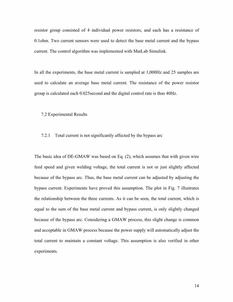
7.2.1 Total current is not significantly affected by the bypass arc
The basic idea of DE-GMAW was based on Eq. (2), which assumes that with given wire
feed speed and given welding voltage, the total current is not or just slightly affected
because of the bypass arc. Thus, the base metal current can be adjusted by adjusting the
bypass current. Experiments have proved this assumption. The plot in Fig. 7 illustrates
the relationship between the three currents. As it can be seen, the total current, which is
equal to the sum of the base metal current and bypass current, is only slightly changed
because of the bypass arc. Considering a GMAW process, this slight change is common
and acceptable in GMAW process because the power supply will automatically adjust the
total current to maintain a constant voltage. This assumption is also verified in other
experiments.

15
7.2.2 Voltage across the power resistor group only changes slightly
Experiments have been done to verify another assumption: the bypass arc voltage is
almost independent of the bypass current. To this end, the voltage between the two
electrodes (the GMAW torch and the bypass GTAW torch) was monitored. As shown in
Fig. 8, this voltage is only slightly changed with a mean value of 27.5volts and a standard
deviation of 2.2volts while there is a very large change in the bypass current. This voltage
is the difference between the pre-set GMAW voltage and the voltage across the power
resistors. With a constant GMAW voltage, it can be concluded that the voltage across the
adjustable power resistors only slightly changes with the bypass current.
7.2.3 Bypass current can be adjusted in a large range
In DE-GMAW, the base metal current is adjusted or controlled at a desired level by
dynamically adjusting the bypass current. In order to have a good controllability, the
power resistors must be able to adjust the bypass current in a large range. Experiments
(Figs. 9-13) show that the proposed design of the power resistor group can adjust the
bypass current in a large range. In the proposed system, the closed-loop control is applied
right after the DE-GMAW process is successfully established as can be detected from the
bypass current. However, to demonstrate the effect of the closed-loop control in
comparison with open-loop system, the closed-loop control was applied with a delay in
Experiment 1 after the DE-GMAW process was successfully established.

16
In Experiment 1 shown in Fig. 9, the total current was 323amps (average over the
experiment period), but the base metal current needed to be controlled at 220amps. Based
on the DE-GMAW design, the extra 103amps current must flow back to the power
supply through the bypass arc. That means the bypass current is 103amps. (Because the
total current reduced gradually, the bypass current should also reduce gradually.) To that
end, the control system outputs a control signal between 2 and 3. Here the control signal
is the number of IGBTs in “ON” status or how many individual power resistors combined
to obtain the required resistance. As can be seen in the figure, the base metal current has
been successfully controlled at its desired level 220amps. However, before the closed-
loop control was applied approximately at t=0.85sec., the base metal current was below
the desired level. Moreover, the bypass current actually increased so that the base metal
current even decreased after t=0.7 sec. approximately. After the closed-loop control was
applied approximately at t=0.85 sec., the increase in the bypass current was stopped so
that the base metal current started to increase. The effect of the closed-loop control is thus
clearly seen.
In Experiment 2 (Fig. 10), the total current was increased to 407amps, but the base metal
current needed to be controlled at 235amps. To this end, a bypass current of 171amps
was applied by adjusting the power resistors. (Here the total current and the bypass
current are the average of the measured values, so their difference should be very close to
the desired base metal current, but sometimes not equal to the desired value.) As can be
seen, in the beginning of the experiment, the base metal current was higher than the
desired value, thus the control algorithm tried to draw more current to the bypass loop by

17
minimizing the bypass resistance using all parallel resistors. As a result, the base metal
current rapidly reached its desired value. To maintain this level, the control signal then
falls into the range of 3 to 4. However, in Experiment 1, the control signal was from 2 to
3. Its resistance was higher so that its bypass current was smaller at 103amps.
In Experiment 3 shown in Fig. 11, the desired base metal current was still 220amps, but
the total current was increased to 409amps. In the beginning of the experiment, the base
metal current was significantly lower than the desired value. However, the control
algorithm rapidly reduced the control signal to increase the resistance of the bypass loop.
As a result, the base metal current quickly reached its desired value approximately at
t=0.5 sec. Because of the quick actions, a small overshoot occurred in the base metal
current. However, the control algorithm immediately increased the control signal to
reduce the resistance of the bypass loop. After 0.2 second approximately (approximately
at t=0.7 sec.), the base metal current was settled at its desired value.
In Experiment 4 illustrated in Fig. 12, the bypass current was 200amps, and the total
current was 453amps. This resulted in a base metal current of 253amps (mean value),
which is very close to the desired base metal current. It can be seen that the control signal
is almost 4. That means all the resistors are parallel used to obtain a bypass current as
high as 200amps.
Experiment 5 shown in Fig. 13 presents an example in which the bypass current is larger
than the base metal current. In this example, the total current was approximately 200amps.

18
Before the bypass arc was established at t=3 second, the process was the conventional
GMAW and the liquid metal was transferred in globular mode. After the bypass arc was
introduced, the spray transfer was achieved although the base metal current was only
60amps approximately.
Furthermore, all these experiments (Figs. 9-13) verify the assumption that the total
current is not significantly affected by the bypass arc.
7.2.4 Response time of the control algorithm
Response speed is important in the control system design. It must respond fast enough to
stabilize the system if there is any disturbance. Although the welding system is a thermal
system which usually responds slowly, the workpiece may be burnt through if the control
system can not respond fast enough. Fig. 14 shows that it takes about 0.4 sec for the
controlled DE-GMAW system to completely settle down. This settling time appears fast
enough for the DE-GMAW process.
7.2.5 Bypass arc can significantly decrease the base metal heat input.
Fig. 15 shows example welds for bead-on-plate tests and lap joint tests, respectively, with
the controlled DE-GMAW process. And their current signals are plotted in Fig. 11 and
Fig. 7, respectively. The travel speed is 1.65m/min (65IPM), which doubles the normal
GMAW welding speed. The wire feed speed was 13.97m/min (550IPM). It can be seen

19
that a very smooth weld without spatter was obtained with long weld ripples because of
the high travel speed. In Fig. 15 (b), the lap joint test was performed with DE-GMAW
from left to right. As can be seen in the figure, without the bypass arc, the workpiece was
burnt through. This verifies the DE-GMAW can decrease the base metal heat input.
Compared to normal GMAW welds, both welds in Fig. 15 have narrower widths and
larger heights of reinforcement (Fig. 16), which is very common in high speed welding.
7.2.6 Effect of the bypass arc on metal transfer and penetration
Fig. 17 gives two frames of images extracted from a high speed video. In this experiment,
the wire feed speed is 5.33m/min (210IPM) and the melting current is 198amps. Without
the bypass arc (Fig. 17 (a)), the metal transfer is in globular mode because the melting
current is only 198amps, lower than the critical current which is approximately 225amps
for 0.045in.-diameter low carbon wire (Refs. 9-11). However, after the bypass arc was
ignited, the metal transfer becomes spray mode (Fig. 17 (b)). Because the wire feed speed
is not changed, the melting current is not changed and stays at 198amps. Hence, the
critical current needed for the spray transfer was decreased.
A lower critical current is also beneficial for decreasing the droplet impact which affects
the penetration depth. Fig. 17 suggests that the bypass arc pushes the arc spot backward
about 5mm, which is about half length of the weld pool. The droplets thus will fall into
the molten metal instead of the base metal directly. The molten metal will reduce the

20
digging action to the base metal. This effect would further reduce the penetration in
addition to the reduced the base metal current and heat input.
8. Conclusion
A double-electrode GMAW system has been developed by adding a non-consumable
tungsten electrode in a conventional GMAW to form a bypass loop. The conditions for
establishing and maintaining a stable process were obtained through experiments. The
system utilized an adjustable power resistor group controlled by IGBTs to obtain
different bypass currents. A model has been derived to correlate the change of the
resistance needed to achieve the desired base metal current to the deviation of the base
metal current from its desired level. Experiments verified that the control system
developed can assure a fast enough settling time for the DE-GMAW and that the bypass
current can be adjusted to maintain a desired base metal current in a relatively wide range
of total current.
Acknowledgement
This work is funded by the National Science Foundation under grant DMI-0355324 and
Toyota Motor Manufacturing North America, Inc. The authors sincerely thank Mr. Stave
Byerly from Toyota Motor Manufacturing North America for his technical assistance
during this study.

21
References
1. Waszink, J.H. and Heuvel, G.P.M.V.d. 1982. Heat generation and heat flow in the
filler metal in GMAW welding. Welding Journal. 61: 269s-282s.
2. Ueyama, T., Ohnawa, T., Tanaka, M., and Nakata, K. 2005. Effects of torch
configuration and welding current on weld bead formation in high speed tandem pulsed
gas metal arc welding of steel sheets. Science and Technology of Welding and Joining.
10(6): 750-759.
3. Tsushima, S. and Kitamura, M. 1996. Tandem electrode AC-MIG welding -
development of AC-MIG welding process (report 4). Welding Research Abroad. 42(2):
26-32.
4. Church, J. 2001. T.I.M.E. process produces fracture-proof welds. Welding Design
and Fabrication. 74(5): 32-35.
5. Lahnsteiner, R. 1992. The T.I.M.E. process - an innovative MAG welding process.
Welding Review International. 11(1): 17-20.
6. Talkington, J.E. 1998. Variable Polarity Gas Metal Arc Welding, in Welding
Engineering. The Ohio State University: Columbus, Ohio.
7. Chen, K.-X., Li, H.-Q., and Li, C.-X. 2004. Progress in variable polarity plasma arc
welding. Hanjie Xuebao/Transactions of the China Welding Institution. 25(1): 124-128.
8. Cary, H. and Chaisson, W. 1986. Variable Polarity Plasma Arc Welding. Metairie,
LA, USA: Aluminum Assoc, Washington, DC, USA.
9. O'Brien, R.L.1991. Welding Handbook, Vol. 2: Welding Processes, 8th edition. 8th
ed: American Welding Society.

22
10. Kim, Y.S. and Eagar, T.W. 1993. Analysis of metal transfer in gas metal arc welding.
Welding Journal. 72(6): 269-s to 278-s.
11. Lancaster, J.F.1986. The Physics of Welding, 2nd Edition: International Institute of
Welding, Pergamon Press, Oxford.

23
Figure Captions
Fig. 1 Proposed DE-GMAW System.
Fig. 2 Relationship between tungsten electrode, welding wire and workpiece.
Fig. 3 Controllable Power Resistor Group.
Fig. 4 Electrical Simplification of DE-GMAW.
Fig. 5 Control System of DE-GMAW Process.
Fig. 6 Flowchart for the Control Algorithm.
Fig. 7 Current relationship. WFS = 14m/min (550IPM).
Fig. 8 Bypass voltage is only slightly affected by the bypass current.
Fig. 9 Experiment 1: Base metal current controlled at 220amps with bypass current at
103amps. The close-loop control was applied approximately at t = 0.085sec.
Fig. 10 Experiment 2: Base metal current controlled at 235amps with bypass current at
171amps.
Fig. 11 Experiment 3: Base metal current controlled at 220amps with bypass current at
189amps.
Fig. 12 Experiment 4: Base metal current controlled at 250amps with bypass current at
200amps.
Fig. 13 Experiment 5: Bypass current can be larger than base metal current. In this
experiment, all 4 IGBTs are in “ON” status.
Fig. 14 Response of Controlled DE-GMAW System.
Fig. 15 Example Workpiece Welded with Controlled DE-GMAW Process.
Fig. 16 Cross-section of example weld.

24
Fig. 17 Effect of bypass arc on metal transfer. The total (melting) current in (a) and (b) is
the same and is lower than the critical current. The spray mode is achieved because of the
presence of the bypass arc.
2d
3d
1d
θ
Workpiece
Contact Tip
Bypass Torch
Fig. 2 Relationship between tungsten electrode,
welding wire and workpiece.
Fig. 1 Proposed DE-GMAW System.

25
*bmI
Controller DE-GMAW Process
bmI N bmIδ
-
Fig. 5 Control System of DE-GMAW Process.
Adjustable Resistor
Bypass Arc
Adjustable Resistor
Bypass Arc
GMAW Arc
Workpiece
GMAW Arc
(a) (b)
Fig. 4 Electrical Simplification of DE-GMAW.
IGBTC
G
E
CG
E
CG
E
R1 R3 R4R2
CG
E
Fig. 3 Controllable Power Resistor Group.

26
Pop the last used resistance 0r and calculate
0r r r= + ∆
Start
Push the current used resistance into stack
Sample currents; Calculate
bmI∆ and r∆
RNr
=
Switch on the first 1N +
IGBTs for a period of / 1R NT +
Switch on the first N
IGBTs for a period of /R NT
End
Push the current used resistance into stack
Fig. 6 Flowchart for the Control Algorithm.

27
4 6 8 10 12 140
50
100
150
200
250
300
350
400
Time (sec)
Cur
rent
(am
p)
WFS = 550 IPM
Base metal currentBypass currentTotal current
Fig. 7 Current relationship. WFS = 14m/min (550IPM).
0.3 0.4 0.5 0.6 0.7 0.850
100
150
200
Cur
rent
(A)
Time(sec)
TIG voltage with different current
0.3 0.4 0.5 0.6 0.7 0.820
25
30
35
Vol
tage
(V)
CurrentVoltage
Fig. 8 Bypass voltage is only slightly affected by the bypass current.

28
0.5 1 1.5 2 2.5 3 3.5 4 4.5 5 5.50
50
100
150
200
250
300
350
Cur
rent
(A)
Time(sec)
Desired = 220A Bypass = 103A Total = 323A
0.5 1 1.5 2 2.5 3 3.5 4 4.5 5 5.50
2
4
6
8
10
12
14
16
Con
trol S
igna
l(Num
ber o
f Res
isto
rs)
Base Metal CurrentBypass CurrentTotal CurrentControl Signal
Fig. 9 Experiment 1: Base metal current controlled at 220amps with bypass current at 103amps. The close-loop control was
applied approximately at t = 0.085sec.
0.5 1 1.5 2 2.5 3 3.5 4 4.5 50
50
100
150
200
250
300
350
400
Cur
rent
(A)
Time (sec)
Desired = 235A Bypass = 171A Total = 407A
0.5 1 1.5 2 2.5 3 3.5 4 4.5 50
2
4
6
8
10
12
14
16
Con
trol S
igna
l(Num
ber o
f Res
isto
rs)
Base Metal CurrentBypass CurrentTotal CurrentControl Signal
Fig. 10 Experiment 2: Base metal current controlled at 235amps with bypass current at 171amps.

29
0.5 1 1.5 2 2.5 3 3.50
50
100
150
200
250
300
350
400
Cur
rent
(A)
Time (sec)
Desired = 220A Bypass = 189A Total = 409A
0.5 1 1.5 2 2.5 3 3.50
2
4
6
8
10
12
Con
trol S
igna
l(Num
ber o
f Res
isto
rs)
Base Metal CurrentBypass CurrentTotal CurrentControl Signal
Fig. 11 Experiment 3: Base metal current controlled at 220amps with bypass current at 189amps.
0.5 1 1.5 2 2.5 3 3.5 40
50
100
150
200
250
300
350
400
450
500
Cur
rent
(A)
Time (sec)
Desired = 250A Bypass = 200A Total = 453A
0.5 1 1.5 2 2.5 3 3.5 40
2
4
6
8
10
12
14
16
Con
trol S
igna
l(Num
ber o
f Res
isto
rs)Base Metal Current
Bypass CurrentTotal CurrentControl Signal
Fig. 12 Experiment 4: Base metal current controlled at 250amps with bypass current at 200amps.

30
0 1 2 3 4 50
50
100
150
200
Time (sec)
Cur
rent
(am
p)
Bypass = 133A Total = 199A
Base metal currentBypass currentTotal current
Fig. 13 Experiment 5: Bypass current can be larger than base metal current. In this experiment, all 4 IGBTs are in “ON” status.
0.4 0.5 0.6 0.7 0.8 0.9 1 1.10
50
100
150
200
250
300
350
400
Cur
rent
(A)
Time (sec)
Desired = 220A Bypass = 189A Total = 409A
0.4 0.5 0.6 0.7 0.8 0.9 1 1.10
2
4
6
8
10
12
Con
trol S
igna
l(Num
ber o
f Res
isto
rs)
Base Metal CurrentBypass CurrentTotal CurrentControl Signal
Fig. 14 Response of Controlled DE-GMAW System.

31
(a) Bead-on-plate
(b) Lap joint
Fig. 15 Example Workpiece Welded with Controlled DE-GMAW Process.
Fig. 16 Cross-section of example weld.

32
2
13 65.1 10 2.2 10I Lm IS
− −= × + × (1)
bm bpI I I= + (2)
0 0 0 0( )( )bp bp bpI r I I r r= + ∆ + ∆ (3)
0 0 0bp bp bpI r I r I r∆ + ∆ + ∆ ∆ = (4)
0 0 0bp bpI r I r∆ + ∆ = (5)
00
bp
bp
Ir r
I∆
∆ = − (6)
bp bmI Iδ∆ = − (7)
0
0bm
bp
rr II
δ∆ = (8a)
0
0bm
bp
rr K II
δ∆ = (8b)
0
RNr r
=+ ∆
(9)
( )/ 1
1R N
N N NT T
N+
+ − = (10)
( )/
1R N
N N NT T
N
+ − = (11)
(a) Without bypass arc: globular transfer (b) With bypass arc: spray transfer
Fig. 17 Effect of bypass arc on metal transfer. The total (melting) current in (a) and (b) is the same and is lower than the critical current. The spray mode is achieved because of the presence of the bypass arc.

33
( )( )
/ 1
/
11
R N
R N
T N N Nratio
T N N N+
+ − = =+ −
(12)