Embed Size (px)
Citation preview
Altech Corp.® • 35 Royal Road • Flemington, NJ 08822-6000 • Phone (908)806-9400 • FAX (908)806-9490 • www.altechcorp.com
DATA SUBJECT TO CHANGE WITHOUT NOTICE
66
R15Industrial Electromagnetic Relays
• Contacts AgNi• For plug-in sockets, 35 mm rail mount or on panel mounting.• Cadmium-free contacts-R15 DPDT, R15 3PDT, R15 4PDT relays• WT (mechanical indicator and lockable front test button) - standard features of
R15 DPDT, R15 3DPT relays in cover, for plug-in sockets. • Relays may be provided with the test buttons (no latching) and plugs (see page 115).• AUCOTEAM, GmbH Berlin - railway standards.
Contact DataNumber and type of contacts DPDT 3PDT 4PDTContact material AgNi AgNi AgCdORated / max. switching voltage AC 250 V / 440 V 250 V / 440 V 250 V / 440 VMin. switching voltage 10 V 10 V 10 VRated load (capacity) AC1 10 A / 250 V AC; 10 A / 277 V AC UL 508 10 A / 250 V AC; 10 A / 277 V AC UL 508 10 A / 250 V AC; 10 A / 277 V AC UL 508
AC15 3 A / 120 V; 1.5 A / 240 V (B300) 3 A / 120 V; 1.5 A / 240 V (B300) 3 A / 120 V; 1.5 A / 240 V (B300)AC3 370 W (single-phase motor. 370 W (single-phase motor. 370 W (single-phase motor.
1/2 HP / 240 V AC UL 508) 1/2 HP / 240 V AC UL 508) 1/2 HP / 240 V AC UL 508)DC1 10 A / 24 V DC (see Fig. 3) 10 A / 24 V DC (see Fig. 3) 10 A / 24 V DC (see Fig. 3)
DC13 0.22 A / 120 V; 0.1 A / 250 V (R300) 0.22 A / 120 V; 0.1 A / 250 V (R300) 0.22 A / 120 V; 0.1 A / 250 V (R300)Min. switching current 5 mA 5 mA 10 mAMax. inrush current 20 A 20 A 20 ARated current 10A 10A 10AMax. breaking capacity AC1 2500 VA 2500 VA 2500 VAMin. breaking capacity 0.3 W 0.3 W 0.5 W Contact resistance ≤ 100 mΩ ≤ 100 mΩ ≤ 100 mΩMax. operating frequency
• at rated load AC1 1200 cycles/hour 1200 cycles/hour 1200 cycles/hour• no load 12000 cycles/hour 12000 cycles/hour 12000 cycles/hour
Coil DataRated voltage 50/60 Hz AC 6 ... 240 V 6 ... 240 V 6 ... 240 V
DC 6 ... 220 V 6 ... 220 V 6 ... 220 VMust release voltage AC: ≥ 0.15 Un; DC: ≥ 0.1 Un AC: ≥ 0.15 Un; DC: ≥ 0.1 Un AC: ≥ 0.15 Un; DC: ≥ 0.1 UvOperating range of supply voltage see page 68 see page 68 see page 68Rated power consumption AC: 2.8 VA 50 Hz; 2.5 VA 60 Hz; DC: 1.5 W AC: 2.8 VA 50 Hz; 2.5 VA 60 Hz; DC: 1.5 W AC: 2.8 VA 50 Hz; 2.5 VA 60 Hz; DC: 1.5 W
InsulationInsulation rated voltage 250 V AC 250 V AC 250 V ACRated surge voltage 2500 V 1.2 / 50 µs 2500 V 1.2 / 50 µs 2500 V 1.2 / 50 µsOvervoltage category III III IIIInsulation pollution degree 3 3 3Dielectric strength
• between coil and contacts 2500 V AC type of insulation: basic 2500 V AC type of insulation: basic 2500 V AC type of insulation: basic• contact clearance 1500 V AC type of clearance: micro-disco. 1500 V AC type of clearance: micro-disco. 1500 V AC type of clearance: micro-disco.• pole - pole 2000 V AC type of insulation: basic 2000 V AC type of insulation: basic 2000 V AC type of insulation: basic
Contact - coil distance• clearance ≥ 3 mm ≥ 3 mm ≥ 3 mm• creepage ≥ 4.2 mm ≥ 4.2 mm ≥ 3.2 mm
General DataOperating / release time (typical) AC: 12 ms / 10 ms; DC: 18 ms / 7 ms AC: 12 ms / 10 ms; DC: 18 ms / 7 ms AC: 12 ms / 10 ms; DC: 18 ms / 7 msElectrical life
• resistive AC1 > 2 x 10⁵; 10 A. 250 V AC > 2 x 10⁵; 10 A. 250 V AC > 2 x 10⁵; 10 A. 250 V AC• cos� see Fig. 2 see Fig. 2 see Fig. 2
Mechanical life (cycles) > 2 x 10⁷ > 2 x 10⁷ > 2 x 10⁷
Dimensions (L x W x H) 35 x 35 x 54.4 mm 35 x 35 x 54.4 mm 35 x 42.5 x 54.5 mmWeight 83 g 83 g 95 gAmbient temperature
• storage -40...+85 °C -40...+85 °C -40...+85 °C• operating AC: -40...+55 °C DC: -40...+70 °C AC: -40...+55 °C DC: -40...+70 °C AC: -40...+55 °C DC: -40...+70 °C
Cover protection category IP 40 PN-EN 60529 IP 40 PN-EN 60529 IP 40 PN-EN 60529Environmental protection RTI PN-EN 116000-3 RTI PN-EN 116000-3 RTI PN-EN 116000-3Shock resistance 10 g 10 g 10 gVibration resistance 5 g 10...150 Hz 5 g 10...150 Hz 5 g 10...150 HzSolder bath temperature max. 270 °C max. 270 °C max. 270 °CSoldering time max. 5 s max. 5 s max. 5 s
E105728

Altech Corp.® • 35 Royal Road • Flemington, NJ 08822-6000 • Phone (908)806-9400 • FAX (908)806-9490 • www.altechcorp.com <#>
TEXTText
DATA SUBJECT TO CHANGE WITHOUT NOTICE
Altech Corp.® • 35 Royal Road • Flemington, NJ 08822-6000 • Phone (908)806-9400 • FAX (908)806-9490 • www.altechcorp.com 67
R15Industrial Electromagnetic Relays
35 13 54.4
53
35
53
13 54.4
+ -
12 (4)
14 (3)
A1 (2)
11 (1)
22 (5)
24 (6)
A2 (7)
21 (8)
+ -
12 (4)
14 (3)
A1 (2)
11 (1) 31 (11)
32 (8)
34 (9)
22 (5) 24 (7)21 (6)
A2 (10)
(pin side view)
(pin side view)
(pin side view)
3PDT
DPDT
4PDT
CONNECTION DIAGRAM DIMENSIONS
CONNECTION DIAGRAM DIMENSIONS
CONNECTION DIAGRAM DIMENSIONS
LOAD CHARTS
Altech Corp.® • 35 Royal Road • Flemington, NJ 08822-6000 • Phone (908)806-9400 • FAX (908)806-9490 • www.altechcorp.com
DATA SUBJECT TO CHANGE WITHOUT NOTICE
68
R15Industrial Electromagnetic Relays
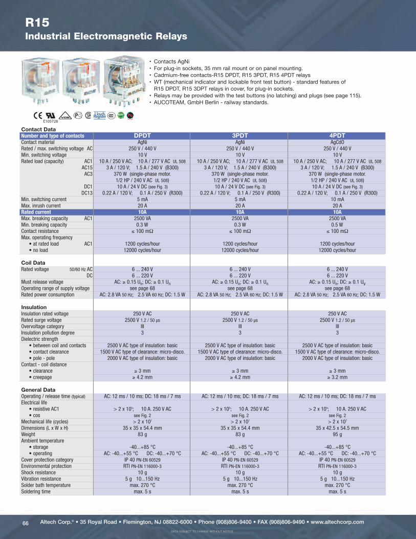
R15 DPDT AC 50/60Hz & DC coilPart Number Coil Voltage Coil Type Coil resistance Coil operating range Options*
(V) at 20 °C in Ω min. (at 20°C) max. (at 55°C) – WT WTLR15-2012-23-1012 12 DC 110 9.6 13.2 xR15-2012-23-1012-WT 12 DC 110 9.6 13.2 xR15-2012-23-1012-WTL 12 DC 110 9.6 13.2 xR15-2012-23-1024 24 DC 430 19.2 26.4 xR15-2012-23-1024-WT 24 DC 430 19.2 26.4 xR15-2012-23-1024-WTL 24 DC 430 19.2 26.4 xR15-2012-23-1110 110 DC 9200 88.0 121.0 xR15-2012-23-1110-WT 110 DC 9200 88.0 121.0 xR15-2012-23-1110-WTL 110 DC 9200 88.0 121.0 xR15-2012-23-5024 24 AC 50/60Hz 75 19.2 26.4 xR15-2012-23-5024-WT 24 AC 50/60Hz 75 19.2 26.4 xR15-2012-23-5024-WTL 24 AC 50/60Hz 75 19.2 26.4 xR15-2012-23-5120 120 AC 50/60Hz 1910 96.0 132.0 xR15-2012-23-5120-WT 120 AC 50/60Hz 1910 96.0 132.0 xR15-2012-23-5120-WTL 120 AC 50/60Hz 1910 96.0 132.0 xR15-2012-23-5230 230 AC 50/60Hz 7080 184.0 253.0 xR15-2012-23-5230-WT 230 AC 50/60Hz 7080 184.0 253.0 xR15-2012-23-5230-WTL 230 AC 50/60Hz 7080 184.0 253.0 xR15 3PDT AC 50/60Hz & DC coilPart Number Coil Voltage Coil Type Coil resistance Coil operating range Options*
(V) at 20 °C in Ω min. (at 20°C) max. (at 55°C) – WT WTLR15-2013-23-1012 12 DC 110 9.6 13.2 xR15-2013-23-1012-WT 12 DC 110 9.6 13.2 xR15-2013-23-1012-WTL 12 DC 110 9.6 13.2 xR15-2013-23-1024 24 DC 430 19.2 26.4 xR15-2013-23-1024-WT 24 DC 430 19.2 26.4 xR15-2013-23-1024-WTL 24 DC 430 19.2 26.4 xR15-2013-23-1110 110 DC 9200 88.0 121.0 xR15-2013-23-1110-WT 110 DC 9200 88.0 121.0 xR15-2013-23-1110-WTL 110 DC 9200 88.0 121.0 xR15-2013-23-5024 24 AC 50/60Hz 75 19.2 26.4 xR15-2013-23-5024-WT 24 AC 50/60Hz 75 19.2 26.4 xR15-2013-23-5024-WTL 24 AC 50/60Hz 75 19.2 26.4 xR15-2013-23-5120 120 AC 50/60Hz 1910 96.0 132.0 xR15-2013-23-5120-WT 120 AC 50/60Hz 1910 96.0 132.0 xR15-2013-23-5120-WTL 120 AC 50/60Hz 1910 96.0 132.0 xR15-2013-23-5230 230 AC 50/60Hz 7080 184.0 253.0 xR15-2013-23-5230-WT 230 AC 50/60Hz 7080 184.0 253.0 xR15-2013-23-5230-WTL 230 AC 50/60Hz 7080 184.0 253.0 xR15 4PDT AC 50/60Hz & DC coilPart Number Coil Voltage Coil Type Coil resistance Coil operating range Options*
(V) at 20 °C in Ω min. (at 20°C) max. (at 55°C) - K WT WTLR15-1014-23-1012 12 DC 110 9.6 13.2 xR15-1014-23-1012-K 12 DC 110 9.6 13.2 xR15-1014-23-1012-L 12 DC 110 9.6 13.2 xR15-1014-23-1012-D 12 DC 110 9.6 13.2 xR15-1014-23-1024 24 DC 430 19.2 26.4 xR15-1014-23-1024-K 24 DC 430 19.2 26.4 xR15-1014-23-1024-L 24 DC 430 19.2 26.4 xR15-1014-23-1024-D 24 DC 430 19.2 26.4 xR15-1014-23-1110 110 DC 9200 88.0 121.0 xR15-1014-23-1110-K 110 DC 9200 88.0 121.0 xR15-1014-23-1110-L 110 DC 9200 88.0 121.0 xR15-1014-23-1110-D 110 DC 9200 88.0 121.0 xR15-1014-23-3024 24 AC 50Hz 72 19.2 26.4 xR15-1014-23-3024-K 24 AC 50Hz 72 19.2 26.4 xR15-1014-23-3024-L 24 AC 50Hz 72 19.2 26.4 xR15-1014-23-3024-D 24 AC 50Hz 72 19.2 26.4 xR15-1014-23-3120 120 AC 50Hz 2300 96.0 132.0 xR15-1014-23-3120-K 120 AC 50Hz 2300 96.0 132.0 xR15-1014-23-3120-L 120 AC 50Hz 2300 96.0 132.0 xR15-1014-23-3120-D 120 AC 50Hz 2300 96.0 132.0 xR15-1014-23-3230 230 AC 50Hz 7900 184.0 253.0 xR15-1014-23-3230-K 230 AC 50Hz 7900 184.0 253.0 xR15-1014-23-3230-L 230 AC 50Hz 7900 184.0 253.0 xR15-1014-23-3230-D 230 AC 50Hz 7900 184.0 253.0 xR15-1014-23-6120 120 AC 60Hz 2000 96.0 132.0 xR15-1014-23-6120-K 120 AC 60Hz 2000 96.0 132.0 xR15-1014-23-6120-L 120 AC 60Hz 2000 96.0 132.0 xR15-1014-23-6120-D 120 AC 60Hz 2000 96.0 132.0 xR15-1014-23-6230 230 AC 60Hz 7000 184.0 253.0 xR15-1014-23-6230-K 230 AC 60Hz 7000 184.0 253.0 xR15-1014-23-6230-L 230 AC 60Hz 7000 184.0 253.0 xR15-1014-23-6230-D 230 AC 60Hz 7000 184.0 253.0 xWT = with mechanical indicator + lockable front test button; WTL = with mechanical indicator + lockable front test button + light indicator (LED)K = with test button without block function; L = with light indicator (LED); D = with surge suppression element (diode); other options available upon requestBOLD - Regular stocked items.

Altech Corp.® • 35 Royal Road • Flemington, NJ 08822-6000 • Phone (908)806-9400 • FAX (908)806-9490 • www.altechcorp.com <#>
TEXTText
DATA SUBJECT TO CHANGE WITHOUT NOTICE
Altech Corp.® • 35 Royal Road • Flemington, NJ 08822-6000 • Phone (908)806-9400 • FAX (908)806-9490 • www.altechcorp.com 69
21 11
24 1222(4)(5)(6)
(1)(8)(7)
12
3
45
6
78
A2
14(3)
(2)A1
18.5
15 3.5
1.1
35
24.2
6
24 22 12 14
5 4 3
A2
7 8 1 2
21 11 A1
2.3
Ø
1.5
6.4
30
38
7.8
2568
.2
PZ8 for R15 DPDTScrew terminalsMax. tightening momentfor the terminal: : 0.7 Nm35 mm rail mountacc. to PN-EN 60715or on panel mounting 68.2 x 38 x 24.2 mm Two poles10 A, 250 V AC
CONNECTIONDIAGRAM
PZ11 0031
DIMENSIONS
56 34
7 7 218A2 A1A2 1121
14122224
A1A2
36.2 30
Ø3
27.2
35.5
4
38.2
73
3.5
GZP8 for R15 DPDTScrew terminalsMax. tightening momentfor the terminal: 0.5 Nm35 mm rail mountacc. to PN-EN 60715or on panel mounting73 x 38.2 x 27.2 mm Two poles12 A, 300 V AC
CONNECTIONDIAGRAM
DIMENSIONS
R15Industrial Electromagnetic Relays - Plug-in Sockets and Accessories
Time module COM3T GZP-0035 GZP-0054
GZP8
PZ8
GZP11
9 43578
10 10 1611 2A11121
A1A2
31A2A2
121422243234
27.25.
53
4
2.6
3
Ø3
38.2
37
3.5
30
GZP11 for R15 3PDTScrew terminalsMax. tightening momentfor the terminal: : 0,5 Nm35 mm rail mountacc. to PN-EN 60715or on panel mounting73 x 38.2 x 27.2 mmThree poles12 A, 300 V AC
CONNECTIONDIAGRAM
DIMENSIONS
Time module COM3T GZP-0035 GZP-0054All accessories are sold separately.
Altech Corp.® • 35 Royal Road • Flemington, NJ 08822-6000 • Phone (908)806-9400 • FAX (908)806-9490 • www.altechcorp.com
DATA SUBJECT TO CHANGE WITHOUT NOTICE
70
A2(14)A1(13)11(3)
41(12)31(9)21(6)14(2)
1413
129
8
6
5
3
2 11
10741
44(11)34(8)24(5)12(1)
42(10)32(7)22(4)
59.3
81.2
96.8
46.2
9.4 16
.3
8.6
3.5
14 (2) 21 (6)
22 (4)
31 (9)
32 (7)
41 (12)
42 (10)
11 (3)
)11(44)1(21
A1 (13)
24 (5)
A2 (14)
34 (8)
35
33.3
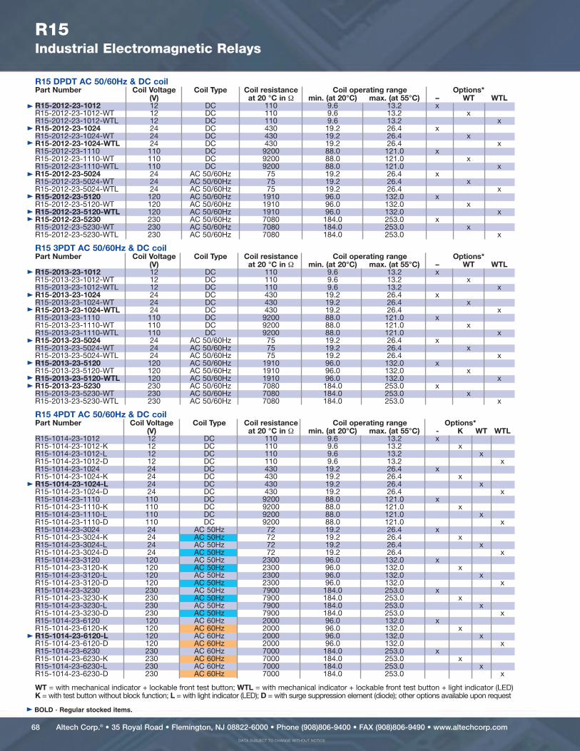
R15Industrial Electromagnetic Relays - Plug-in Sockets and Accessories
GZ14U for R15 4PDTScrew terminalsMax. tightening momentfor the terminal: : 0.7 Nm35 mm rail mountacc. to PN-EN 6071596.8 x 46.2 x 33.3 mmFour poles10 A, 250 V AC
See Relay Socket Combinations on pages 104-109
GZ14 0737
CONNECTIONDIAGRAM DIMENSIONS
(11)(10)34
48
(3)(2)(1)(9)A131A2 11 14
11 1109 3
2
22
57 6
2432(8)
21(7) (6)
12(5) (4)
18.5
15 3.5
1.1
35
24.2
2.3
Ø
1.5
6.4
30
38
5268.2 7.
8
PZ11 for R15 3PDTScrew terminalsMax. tightening momentfor the terminal: : 0.7 Nm35 mm rail mountacc. to PN-EN 60715or on panel mounting68.2 x 38 x 24.2 mmThree poles10 A, 250 V AC
CONNECTIONDIAGRAM
PZ11 0031
PZ11
GZ14ZU
DIMENSIONS
All accessories are sold separately.
Altech Corp.® • 35 Royal Road • Flemington, NJ 08822-6000 • Phone (908)806-9400 • FAX (908)806-9490 • www.altechcorp.com <#>
TEXTText
DATA SUBJECT TO CHANGE WITHOUT NOTICE
Altech Corp.® • 35 Royal Road • Flemington, NJ 08822-6000 • Phone (908)806-9400 • FAX (908)806-9490 • www.altechcorp.com 71
R15Industrial Electromagnetic Relays - Plug-in Sockets and Accessories
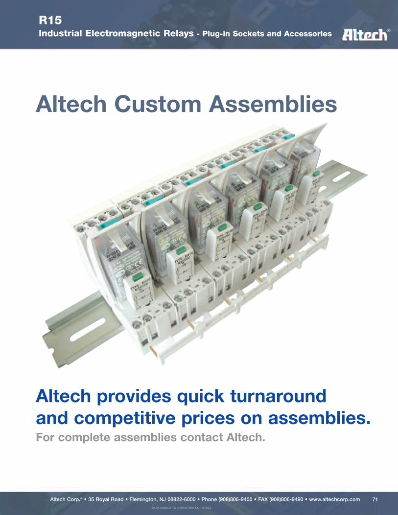
Altech Custom Assemblies
Altech provides quick turnaroundand competitive prices on assemblies.For complete assemblies contact Altech.