Embed Size (px)
Citation preview
Drainage & Erosion Control Report
Centralia College Knoll Parking Lot Centralia, WA
September 2016
Centralia College Campus 2 of 9 Drainage and Erosion Control Report
TABLE OF CONTENTS
Stormwater Site Plan
Cover Sheet ....................................................................................................................................... 1 Table of Contents .............................................................................................................................. 2 Project Engineer’s Certification ........................................................................................................ 3 Section 1: Project Overview .............................................................................................................. 4 Section 2: Site Conditions ................................................................................................................. 5 Existing Site Conditions ............................................................................................................ 5
Soils Information ...................................................................................................................... 5
Section 3: Offsite Analysis ................................................................................................................. 5-6 Qualitative Upstream Analysis ................................................................................................. 5
Qualitative Downstream Analysis ............................................................................................. 5-6 Section 4: Summary of Minimum Requirements .............................................................................. 6 Summary of Compliance ............................................................................................................ 6 Section 5: Permanent Stormwater Control Plan ............................................................................... 6-8 Existing Site Hydrology .............................................................................................................. 6-7 Developed Site Hydrology ......................................................................................................... 7 Stormwater Storage .................................................................................................................. 7-8 Flow Control System .................................................................................................................. 8
Performance Standards and Goals ........................................................................................... 8 Water Quality System ................................................................................................................ 7 Conveyance System Analysis and Design ................................................................................... 7 Section 6: Permits ............................................................................................................................. 8 Section 7: Construction Stormwater Pollution Prevention Plan ....................................................... 8
Appendices
Appendix 1: Site Vicinity Map Appendix 2: Determination of Minimum Requirements Worksheet Appendix 3: Basin Map Exhibit Appendix 4: Design Calculations & Computations Appendix 5: Stormwater Plan Sheets Appendix 6: Construction Stormwater Pollution Prevention Plan Appendix 7: Maintenance Plan Appendix 8: Geotechnical Report Appendix 9: FEMA Flood Insurance Rate Map
Centralia College Campus 3 of 9 Drainage and Erosion Control Report
PROJECT ENGINEER’S CERTIFICATION
The technical material and data contained in these documents were prepared under the supervision and direction of the undersigned, whose seal, as a professional engineer to practice as such is affixed below.
Tyrell Bradley, PE Date Project Manager [email protected] (360) 352-1465
PRELIMINARY
Centralia College Campus 4 of 9 Drainage and Erosion Control Report
DRAINAGE REPORT The following report was prepared for the proposed school parking lot project that is located at 112-114 S King Street, 709-717 Centralia College Boulevard, and 115-123 S Washington Avenue, Centralia, WA 98531. This report was prepared to comply with the minimum technical standards and requirements that are set forth in the 2012
Department of Ecology Stormwater Management Manual for Western Washington (SWMMWW). SECTION 1: PROJECT OVERVIEW Project Proponent: Centralia College 600 Centralia College Boulevard Centralia, WA 98531
Parcel Numbers: 000134002000, 000133001000, 000131000000, 000134003000, 000130000000, 000129000000, 000128000000
Total Parcel Area: 0.95 acres Current Zoning: Residential/City Zoning at Project Completion: OSPF - Open Space Public Facility Site Address: 112-114 S King Street 709-717 Centralia College Boulevard 115-123 S Washington Avenue Centralia, WA 98531 Section, Township Range: Section 8, Township 14N, Range 2W, W.M. The proposed Centralia College Knoll Parking Lot site is located to the north west of campus and is on the southern half of the block located on Centralia College Boulevard and S Washington Avenue. Prior to construction, Centralia College will work with the City of Centralia to demolish the 7 existing houses, foundations, asphalt and gravel drive aisles, fencing, and any other miscellaneous structures. Upon completion of demolition, the 7 parcels will be combined into one parcel and rezoned to OSPF. The proposed single parcel will be 32,370 square-feet. A parking lot is planned to be constructed on the proposed parcel. Stormwater runoff generated on site will be separated into 2 drainage basins. The stormwater runoff in both basins will sheet flow to one of the five proposed bio-retention cells that provides water quality and infiltration/detention. Specifically, the proposed site improvements/construction activities for this project include the following:
• Site preparation, grading, and erosion control activities • Construction of parking lot • Construction/installation of on-site water quality and flow-control/infiltration facilities
A site vicinity map of the proposed project location is enclosed herein as Appendix 1. Minimum requirements 1-10 are required for this project. A worksheet for determining the number of Minimum Requirements for this project has been prepared and is enclosed herein as Appendix 2.
Centralia College Campus 5 of 9 Drainage and Erosion Control Report
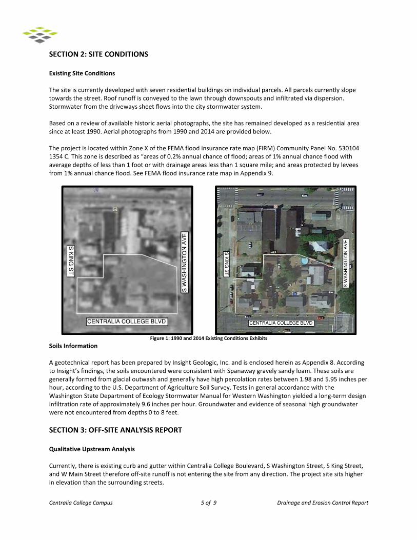
SECTION 2: SITE CONDITIONS
Existing Site Conditions
The site is currently developed with seven residential buildings on individual parcels. All parcels currently slope towards the street. Roof runoff is conveyed to the lawn through downspouts and infiltrated via dispersion. Stormwater from the driveways sheet flows into the city stormwater system. Based on a review of available historic aerial photographs, the site has remained developed as a residential area since at least 1990. Aerial photographs from 1990 and 2014 are provided below. The project is located within Zone X of the FEMA flood insurance rate map (FIRM) Community Panel No. 530104 1354 C. This zone is described as “areas of 0.2% annual chance of flood; areas of 1% annual chance flood with average depths of less than 1 foot or with drainage areas less than 1 square mile; and areas protected by levees from 1% annual chance flood. See FEMA flood insurance rate map in Appendix 9.
Figure 1: 1990 and 2014 Existing Conditions Exhibits
Soils Information
A geotechnical report has been prepared by Insight Geologic, Inc. and is enclosed herein as Appendix 8. According to Insight’s findings, the soils encountered were consistent with Spanaway gravely sandy loam. These soils are generally formed from glacial outwash and generally have high percolation rates between 1.98 and 5.95 inches per hour, according to the U.S. Department of Agriculture Soil Survey. Tests in general accordance with the Washington State Department of Ecology Stormwater Manual for Western Washington yielded a long-term design infiltration rate of approximately 9.6 inches per hour. Groundwater and evidence of seasonal high groundwater were not encountered from depths 0 to 8 feet. SECTION 3: OFF-SITE ANALYSIS REPORT
Qualitative Upstream Analysis
Currently, there is existing curb and gutter within Centralia College Boulevard, S Washington Street, S King Street, and W Main Street therefore off-site runoff is not entering the site from any direction. The project site sits higher in elevation than the surrounding streets.
Centralia College Campus 6 of 9 Drainage and Erosion Control Report
Qualitative Downstream Analysis
On-site generated stormwater runoff from the proposed development project will be routed to on-site bio-retention facilities. 100% of the stormwater runoff from the project will be collected, treated on-site, and released into the ground. In the event that all of the on-site stormwater facilities fail water will sheet flow west down Centralia College Boulevard and into China Creek, which is consistent with the natural historic drainage pattern. Downstream impacts are not anticipated. SECTION 4: SUMMARY OF MINIMUM REQUIREMENTS
Summary of Compliance
The stormwater design complies with all 10 minimum requirements as follows: Minimum Requirement #1 – Preparation of Stormwater Site Plans – This summary is contained within the stormwater site plan. Minimum Requirement #2 – Construction Stormwater Pollution Prevention – A pollution prevention plan has been included within the stormwater site plan which describes the 12 required elements. Further, an erosion control plan has been prepared and is part of the engineering plan set. Minimum Requirement #3 – Source Control of Pollution – The project owner has been made aware of the requirements for source control for pollution prevention. Minimum Requirement #4 – Preservation of Natural Drainage Systems and Outfalls – Runoff from the project site currently flows into the streets and into the catch basins along the curb and gutters. Stormwater runoff from the developed site will be less than the natural drainage system. In the event that the on-site stormwater system fails, stormwater will flow along Centralia College Boulevard and into China Creek, which is consistent with the natural historic drainage pattern. Minimum Requirement #5 – On-site Stormwater Management, including Easements and Setbacks – Stormwater runoff will be collected and conveyed to four bio-retention cells where runoff will receive flow control and water quality treatment prior to being infiltrated on-site. Minimum Requirement #6 – Runoff Treatment – Runoff treatment is provided by the bio-retention cells containing bio-retention soil mix in accordance with Volume V of the Department of Ecology’s Stormwater Management
Manual for Western Washington BMP T7.30. The bio-retention soil mix provides basic water quality treatment. Minimum Requirement #7 – Flow Control – Runoff from the site will be conveyed to bio-retention cells and infiltrated on site. No flow control system is required. Minimum Requirement #8 – Wetlands Protection – There are no known wetlands on-site. Minimum Requirement #9 – Basin/Watershed Planning – The site will act as its own watershed and will meet the minimum requirements of the SMMWW. No additional watershed planning is necessary. Minimum Requirement #10 – Operation and Maintenance – An operation and maintenance manual is included with this stormwater site plan. Refer to Appendix 7 for additional information.
Centralia College Campus 7 of 9 Drainage and Erosion Control Report
SECTION 5: PERMANENT STORMWATER CONTROL PLAN
Existing Site Hydrology
The project site is generally flat and sloped towards their respective roadways at slopes carrying from 1% to 3%. The current project site does not have a detention or water quality system; the stormwater runoff that exits the site flows into the city stormwater system. The pre-developed site was modeled in the forested condition using hydrologic group A/B soils. Sizing calculations were prepared using the Western Washington Hydrology Model 2012 (WWHM 2012). Please see the Existing Conditions hydrology calculations in Appendix 4. Developed Site Hydrology
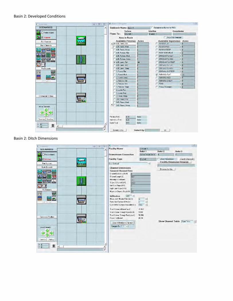
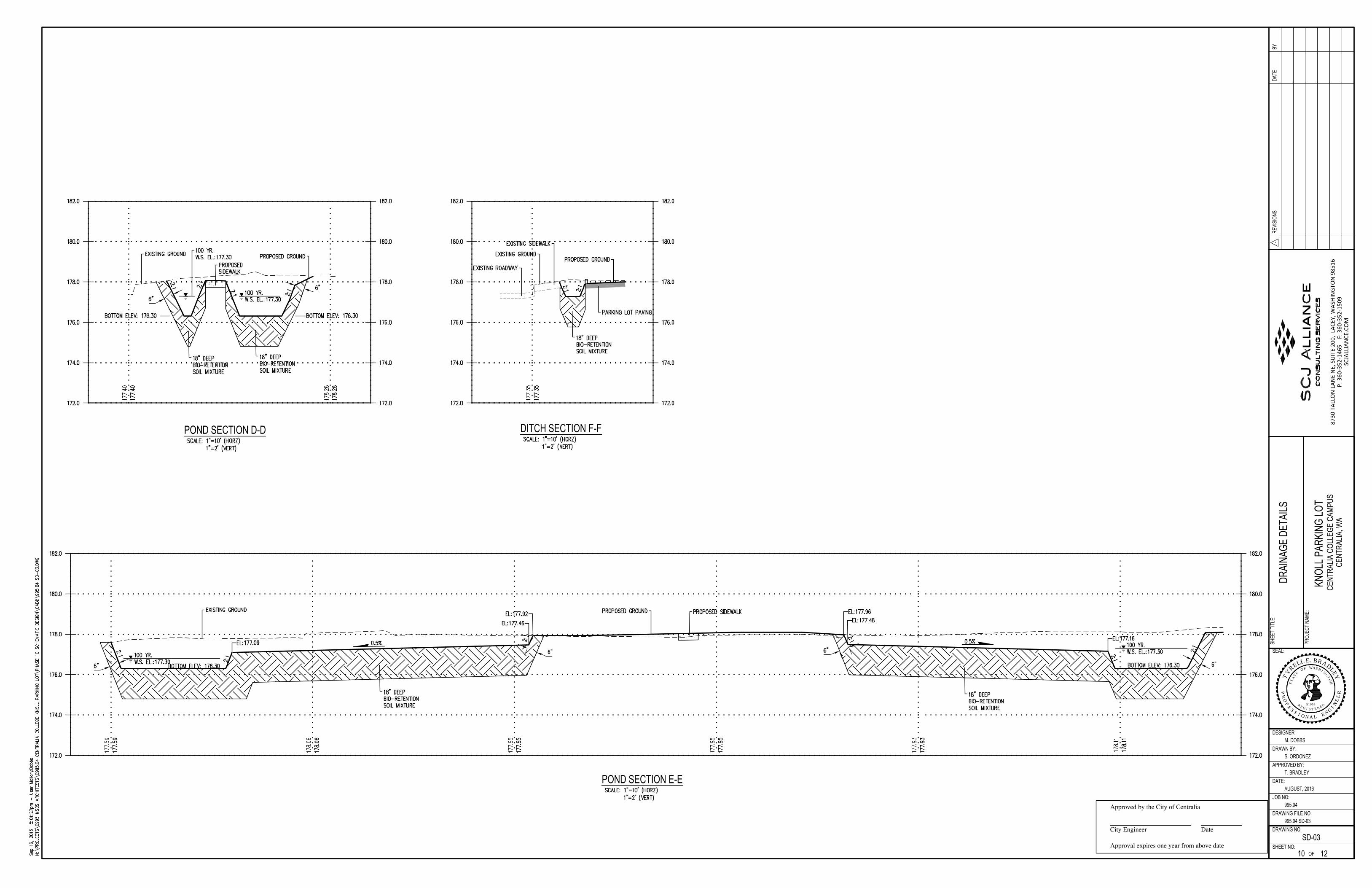
The developed site will consist of basins 1 and 2. Stormwater runoff generated within basin 1 will sheet flow to two bio-retention cells and one bio-retention swale that drains to the bio-retention cell in the SW corner of the site. An equalizer pipe will be placed between the two bio-retention cells and therefore are modeled as one facility in WWHM 2012. The bio-retention swale and bio-retention cells have been sized to provide treatment per Volume V of the 2012 Department of Ecology’s Stormwater Management Manual for Western Washington BMP T7.30 and infiltrate 100% of stormwater runoff generated in basin 1. Stormwater runoff generated within basin 2 will sheet flow to three bio-retention cells and one bio-retention swale that drains to the bio-retention cell in the SE corner of the site. An equalizer pipe will be placed between the three bio-retention cells and therefore are modeled as one facility in WWHM 2012. Basin 2 requires further storage to infiltrate 100% of the stormwater runoff, therefore an underground rock gallery will be placed between the two southernmost facilities. The underground rock gallery was increased by 25% to increase storage for basin 1 in the event of system failure. In the event of a 100-year storm, the bio-retention storage in basin 2 will fill and the water will then overflow into a catch basin that connects to an underground rock gallery. One catch basin is located in both of the southernmost facilities. All proposed facilities have been sized using WWHM 2012. Table 1 below describes the land use of the proposed drainage basins.
LAND TYPE DESIGNATIONS AREA (ACRES) % OF TOTAL AREA
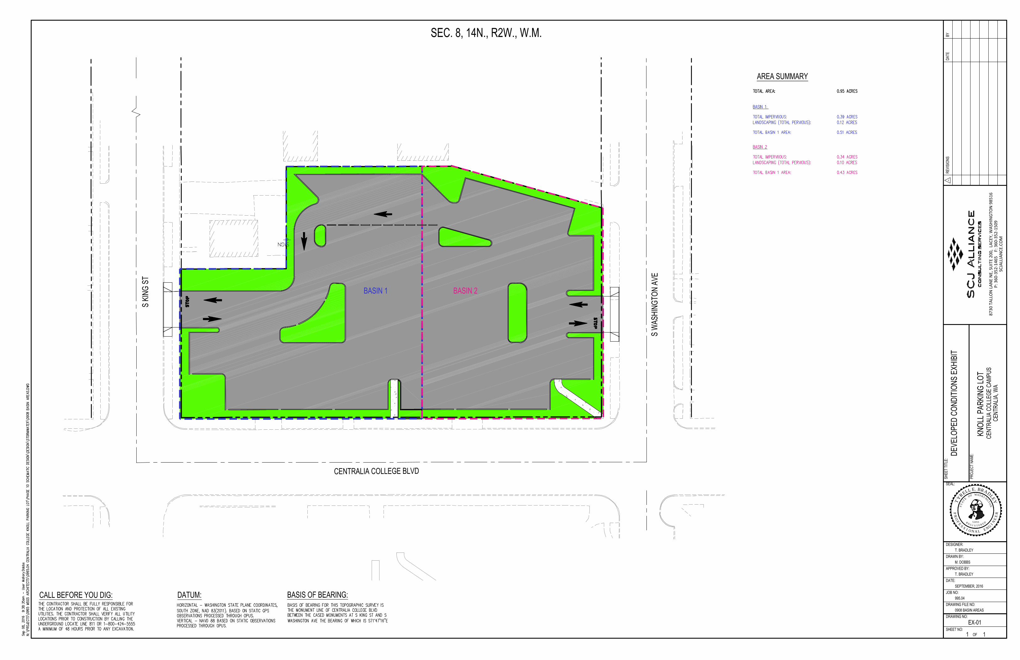
Total Site Area 0.95 100
Existing Pervious Surface 0.63 65
Existing Impervious Surface 0.32 35
Proposed Landscape Areas/or Non-Native Areas 0.74 78
Proposed Impervious Surface 0.21 22
Basin 1 0.51 55
Proposed Landscape Areas/or Non-Native Areas 0.12 13
Proposed Impervious Surface 0.39 41
Basin 2 0.43 45
Proposed Landscape Areas/or Non-Native Areas 0.10 11
Proposed Impervious Surface 0.34 36 Table 1: Land Type Designations Summary Section
Stormwater Storage
Centralia College Campus 8 of 9 Drainage and Erosion Control Report
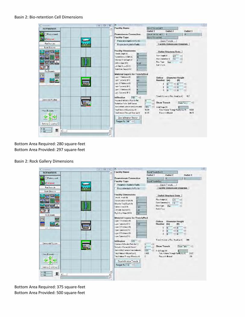
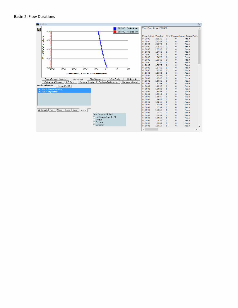
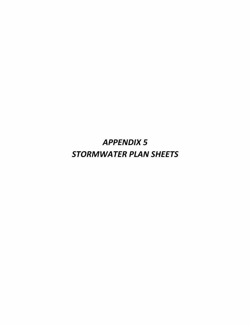
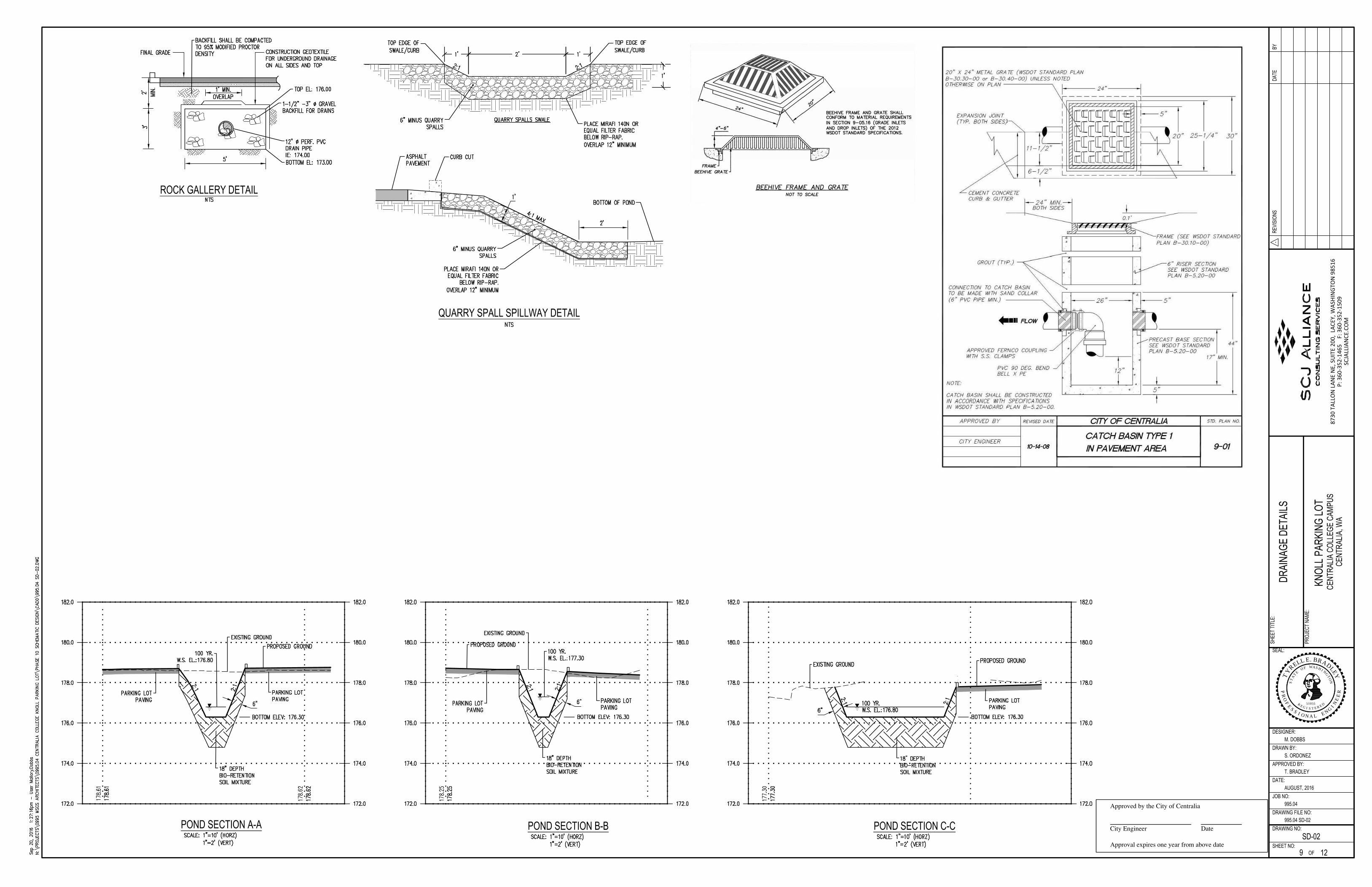
The stormwater infiltration rate evaluation provided a long-term design infiltration rate of approximately 9.6 inches per hour. However, in an effort to be conservative a 50% reduction factor was applied, therefore stormwater calculations were prepared using an infiltration rate of 4-inches/hour. Stormwater infiltration/detention will be provided in bio-retention cells prior to infiltrating into the ground. Basin 1 This basin includes pavement runoff of approximately 17,254 square-feet from the western portion of the project site. Using WWHM 2012, the bottom area of the bio-retention cells needs to be 875 square-feet in order to infiltrate 100% of the stormwater runoff generated within basin 1.Two bio-retention cells connected by an equalizer pipe have been provided for a total bottom area of 895 square-feet, which is greater than the required 875 square-feet. Both of these facilities will provide 6-inches of live storage and 6 inches of freeboard. Basin 2 This basin includes pavement runoff of approximately 15,117 square feet from the eastern portion of the project site. Using WWHM 2012, the bottom area of the bio-retention cells needs to be 280 square-feet in order to infiltrate 100% of the stormwater runoff generated within basin 2. Three bio-retention cells connected by an equalizer pipe have been provided for a total bottom area of 297 square-feet, which is greater than the required 280 square-feet. Basin 2 required an underground rock gallery with a bottom area of 375 square-feet. The rock gallery was increased by 25% to provide a bottom area of 500 square-feet. The increased size of the rock gallery allows the facility from basin 1 to also overflow into the rock gallery in the event of system failure. All three of these bio-retention cells will provide 1-foot of live storage and 6 inches of freeboard. Flow Control System
Flow control has been designed per the WWHM 2012 up to the developed conditions 100-year event. See Appendix 4 for flow control calculations. See the drainage plan and details within Appendix 5.
Performance Standards and Goals
The proposed parking lot is considered a redevelopment project. The basic treatment menu has been selected for this project and oil control and phosphorous control are not required. Flow control has been designed per WWHM 2012 up to the developed conditions 100-year event. See Appendix 2 for the Determination of Minimum Requirements Worksheets.
Water Quality System
Treatment of stormwater runoff from the site will be provided by various bio-retention cells and swales throughout the site. As indicated in Chapter 6 of the Low Impact Development Technical Guidance Manual for
Puget Sound along with Volume V of the 2012 Department of Ecology Stormwater Management Manual for
Western Washington, BMP T7.30, bio-retention cells are an appropriate method for enhanced treatment. The bio-retention cells were designed using WWHM 2012 and pass at least 91% of the influent runoff through the bio-retention soil mixture. A summary of water quality calculations has been included in Appendix 4 of this report. See the drainage plan and details within Appendix 5. SECTION 6: PERMITS A grading and paving permit will need to be secured prior to beginning construction activities. Coverage under Washington State Department of Ecology Phase II National Pollutant Discharge Elimination System Stormwater Permit will also need to be secured prior to beginning construction activities.
Centralia College Campus 9 of 9 Drainage and Erosion Control Report
SECTION 7: CONSTRUCTION STORMWATER POLLUTION PREVENTION PLAN A site specific Construction Stormwater Pollution Prevention Plan will be prepared in accordance with Volume II of the SWMMWW.
END OF DRAINAGE AND EROSION CONTROL REPORT

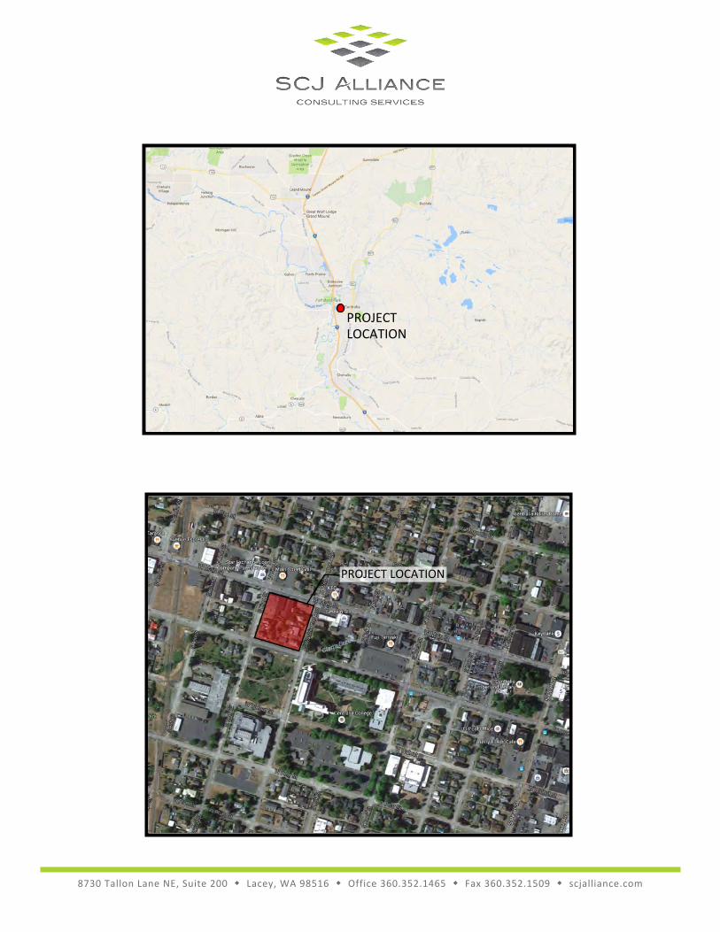
APPENDIX 1
SITE VICINITY MAP
8730 Tallon Lane NE, Suite 200 Lacey, WA 98516 Office 360.352.1465 Fax 360.352.1509 scjalliance.com
PROJECTLOCATION
PROJECT LOCATION
APPENDIX 2
MINIMUM REQUIREMENTS WORKSHEETS
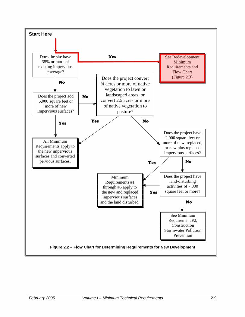
Start Here
Figure 2.2 – Flow Chart for Determining Requirements for New Development
Does the site have 35% or more of
existing impervious coverage?
See Redevelopment Minimum
Requirements and Flow Chart (Figure 2.3)
Does the project add 5,000 square feet or
more of new impervious surfaces?
Does the project convert ¾ acres of ative vegetation to
lawn or landscaped areas, or convert 2.5
acres of native n to pasture
n
vegetatio ?
All Minimum Requirements apply to
the new impervious surfaces and converted
pervious surfaces.
Yes
No
Yes Yes
No
No
Does the project have 2,000 square feet or
more of new, replaced, or new plus replaced impervious surfaces?
Does the project have land-disturbing
activities of 7,000 square feet or more?
Minimum Requirements #1
through #5 apply to the new and replaced impervious surfaces
and the land disturbed.
See Minimum Requirement #2,
Construction Stormwater Pollution
Prevention
Yes No
Yes
No
Does the project convert ¾ acres or more of native
vegetation to lawn or landscaped areas, or
convert 2.5 acres or more of native vegetation to
pasture?
February 2005 Volume I – Minimum Technical Requirements 2-9
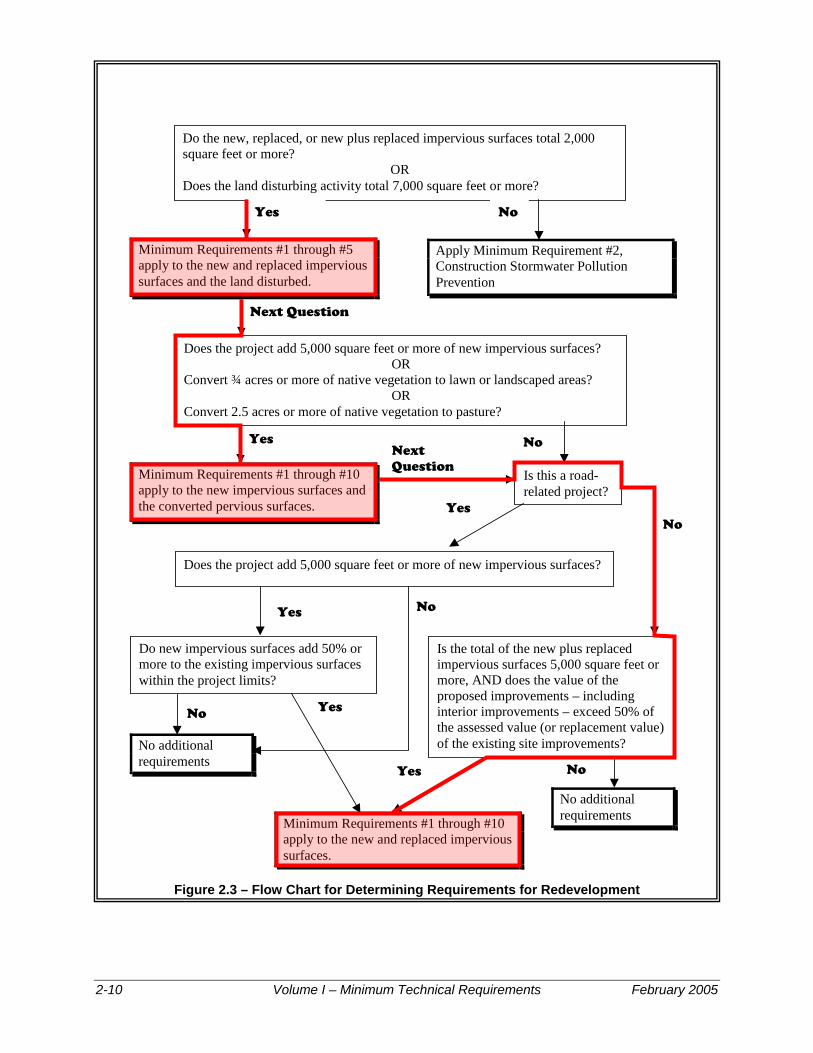
Figure 2.3 – Flow Chart for Determining Requirements for Redevelopment
Apply Minimum Requirement #2, Construction Stormwater Pollution Prevention
Does the project add 5,000 square feet or more of new impervious surfaces? OR
Convert ¾ acres or more of native vegetation to lawn or landscaped areas? OR
Convert 2.5 acres or more of native vegetation to pasture?
Minimum Requirements #1 through #5 apply to the new and replaced impervious surfaces and the land disturbed.
Do the new, replaced, or new plus replaced impervious surfaces total 2,000 square feet or more?
OR Does the land disturbing activity total 7,000 square feet or more?
Minimum Requirements #1 through #10 apply to the new impervious surfaces and the converted pervious surfaces.
Does the project add 5,000 square feet or more of new impervious surfaces?
Is the total of the new plus replaced impervious surfaces 5,000 square feet or more, AND does the value of the proposed improvements – including interior improvements – exceed 50% of the assessed value (or replacement value) of the existing site improvements?
No additional requirements
Do new impervious surfaces add 50% or more to the existing impervious surfaces within the project limits?
No additional requirements
Minimum Requirements #1 through #10 apply to the new and replaced impervious surfaces.
Yes No
Next Question
Yes
Yes
Yes
Yes
Next Question
No
No
No
No
Is this a road-related project?
Yes No
2-10 Volume I – Minimum Technical Requirements February 2005

APPENDIX 3
BASIN MAP EXHIBIT
S W
AS
HIN
GT
ON
A
VE
S K
IN
G S
T
CENTRALIA COLLEGE BLVD
BASIN 1 BASIN 2
SEC. 8, 14N., R2W., W.M.
JOB NO:
DRAWING FILE NO:
DATE:
DESIGNER:
BY
DA
TE
RE
VIS
IO
NS
DRAWN BY:
SH
EE
T T
IT
LE
:
OF
DRAWING NO:
SHEET NO:
PR
OJE
CT
N
AM
E:
SEAL:
APPROVED BY:
KN
OLL P
AR
KIN
G LO
T
CE
NT
RA
LIA
, W
A
T. BRADLEY
T. BRADLEY
SEPTEMBER, 2016
995.04
1
CE
NT
RA
LIA
C
OLLE
GE
C
AM
PU
S
8730
TAL
LON
LAN
E N
E, S
UIT
E 20
0, L
ACEY
, WAS
HIN
GTO
N 9
8516
P: 3
60-3
52-1
465
F:
360
-352
-150
9SC
JALL
IAN
CE.C
OM
CALL BEFORE YOU DIG: DATUM: BASIS OF BEARING:
S
E
N
N
I
O
AL
F
E
P
R
O
N
D
51055
I
G
E
R
S
E
R
E
TS
S
T
A
T
E
O
F
WA
S
H
I
G
I
N
E
E
R
G
T
O
N
T
Y
R
E
L
L
E
. B
R
A
D
L
E
Y
DE
VE
LO
PE
D C
ON
DIT
IO
NS
E
XH
IB
IT
0908 BASIN AREAS
EX-01
M. DOBBS
1
AREA SUMMARY

APPENDIX 4
DESIGN CALCULATIONS & COMPUTATIONS
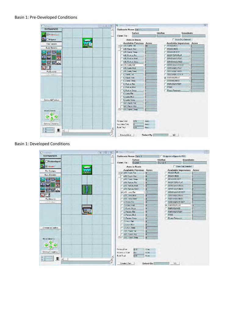
Basin 1: Pre-Developed Conditions
Basin 1: Developed Conditions
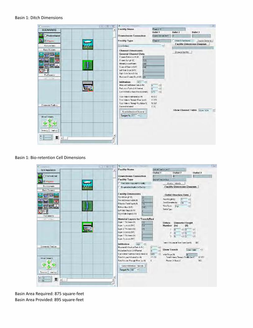
Basin 1: Ditch Dimensions
Basin 1: Bio-retention Cell Dimensions
Basin Area Required: 875 square-feet Basin Area Provided: 895 square-feet
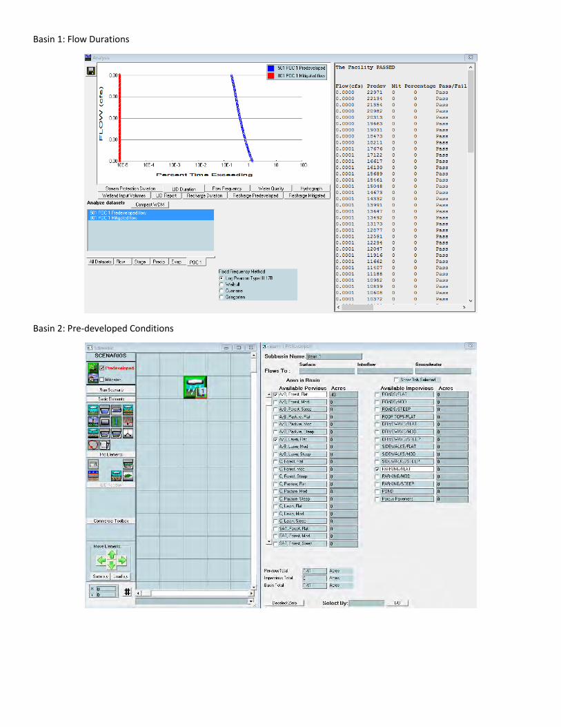
Basin 1: Flow Durations
Basin 2: Pre-developed Conditions
Basin 2: Developed Conditions
Basin 2: Ditch Dimensions
Basin 2: Bio-retention Cell Dimensions
Bottom Area Required: 280 square-feet Bottom Area Provided: 297 square-feet Basin 2: Rock Gallery Dimensions
Bottom Area Required: 375 square-feet Bottom Area Provided: 500 square-feet
Basin 2: Flow Durations
APPENDIX 5
STORMWATER PLAN SHEETS
S W
AS
HIN
GT
ON
A
VE
S K
IN
G S
T
CENTRALIA COLLEGE BLVD
LEGEND
A-A
SD-02
A-A
SD-02
SEC. 8, 14N., R2W., W.M.
JOB NO:
DRAWING FILE NO:
DATE:
DESIGNER:
BY
DA
TE
RE
VIS
IO
NS
DRAWN BY:
SH
EE
T T
IT
LE
:
OF
DRAWING NO:
SHEET NO:
PR
OJE
CT
N
AM
E:
SEAL:
APPROVED BY:
KN
OLL P
AR
KIN
G LO
T
CE
NT
RA
LIA
, W
A
M. DOBBS
T. BRADLEY
AUGUST, 2016
995.04
12
CE
NT
RA
LIA
C
OLLE
GE
C
AM
PU
S
8730
TAL
LON
LAN
E N
E, S
UIT
E 20
0, L
ACEY
, WAS
HIN
GTO
N 9
8516
P: 3
60-3
52-1
465
F:
360
-352
-150
9SC
JALL
IAN
CE.C
OM
CALL BEFORE YOU DIG: DATUM: BASIS OF BEARING:
Approved by the City of Centralia
City Engineer Date
Approval expires one year from above date
S
E
N
N
I
O
AL
F
E
P
R
O
N
D
51055
I
G
E
R
S
E
R
E
TS
S
T
A
T
E
O
F
WA
S
H
I
G
I
N
E
E
R
G
T
O
N
T
Y
R
E
L
L
E
. B
R
A
D
L
E
Y
SCALE IN FEET
0 20 40
DR
AIN
AG
E P
LA
N
995.04 SD-01
SD-01
S. ORDONEZ
8
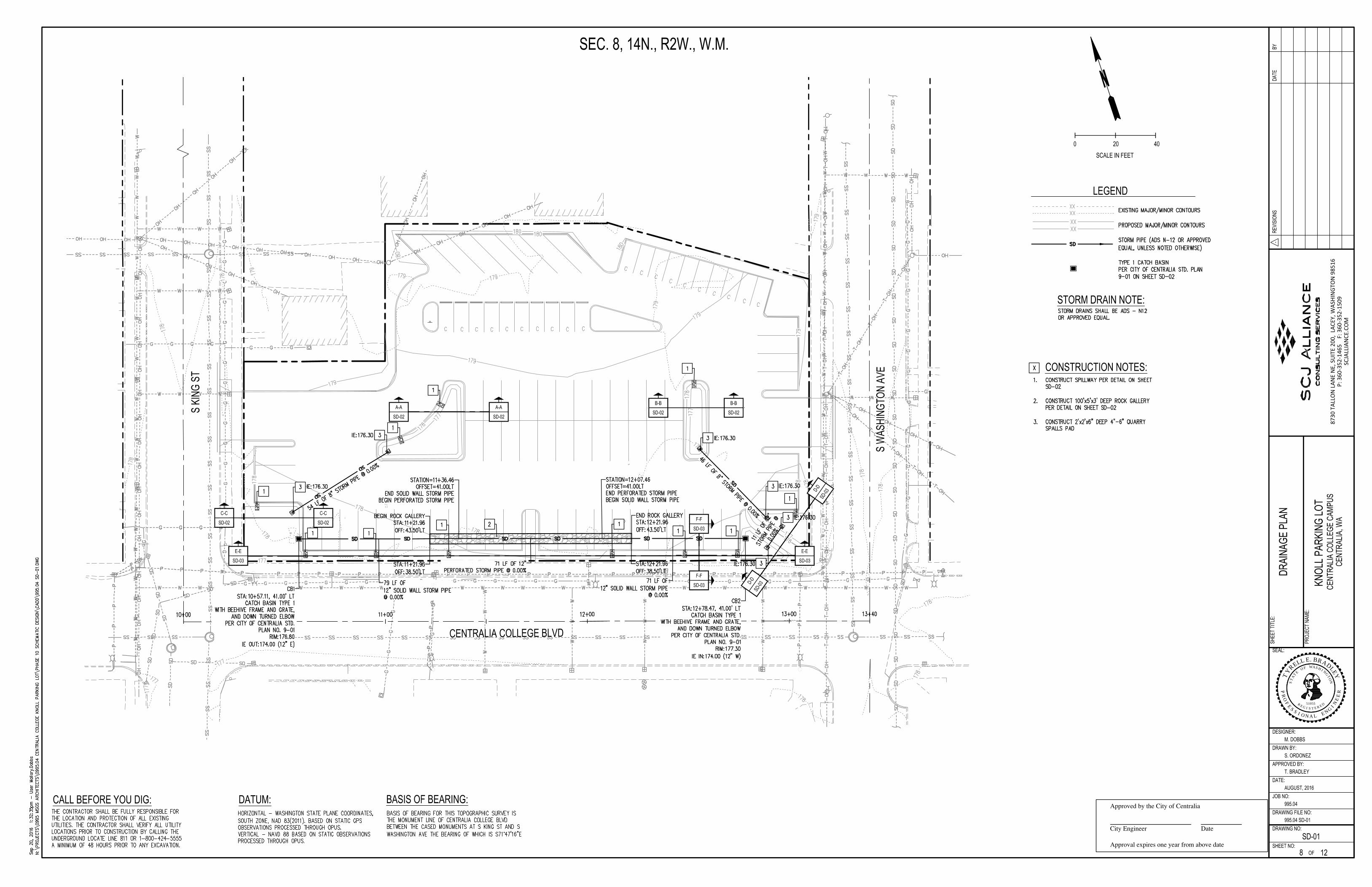
STORM DRAIN NOTE:
CONSTRUCTION NOTES:
B-B
SD-02
B-B
SD-02
C-C
SD-02
C-C
SD-02
E-E
SD-03
E-E
SD-03
D
-
D
S
D
-
0
3
D
-
D
S
D
-
0
3
F-F
SD-03
F-F
SD-03
JOB NO:
DRAWING FILE NO:
DATE:
DESIGNER:
BY
DA
TE
RE
VIS
IO
NS
DRAWN BY:
SH
EE
T T
IT
LE
:
OF
DRAWING NO:
SHEET NO:
PR
OJE
CT
N
AM
E:
SEAL:
APPROVED BY:
KN
OLL P
AR
KIN
G LO
T
CE
NT
RA
LIA
, W
A
M. DOBBS
T. BRADLEY
AUGUST, 2016
995.04
12
CE
NT
RA
LIA
C
OLLE
GE
C
AM
PU
S
8730
TAL
LON
LAN
E N
E, S
UIT
E 20
0, L
ACEY
, WAS
HIN
GTO
N 9
8516
P: 3
60-3
52-1
465
F:
360
-352
-150
9SC
JALL
IAN
CE.C
OM
Approved by the City of Centralia
City Engineer Date
Approval expires one year from above date
S
E
N
N
I
O
AL
F
E
P
R
O
N
D
51055
I
G
E
R
S
E
R
E
TS
S
T
A
T
E
O
F
WA
S
H
I
G
I
N
E
E
R
G
T
O
N
T
Y
R
E
L
L
E
. B
R
A
D
L
E
Y
DR
AIN
AG
E D
ET
AILS
995.04 SD-02
SD-02
S. ORDONEZ
9
QUARRY SPALL SPILLWAY DETAIL
ROCK GALLERY DETAIL
POND SECTION A-A
POND SECTION B-B POND SECTION C-C
JOB NO:
DRAWING FILE NO:
DATE:
DESIGNER:
BY
DA
TE
RE
VIS
IO
NS
DRAWN BY:
SH
EE
T T
IT
LE
:
OF
DRAWING NO:
SHEET NO:
PR
OJE
CT
N
AM
E:
SEAL:
APPROVED BY:
KN
OLL P
AR
KIN
G LO
T
CE
NT
RA
LIA
, W
A
M. DOBBS
T. BRADLEY
AUGUST, 2016
995.04
12
CE
NT
RA
LIA
C
OLLE
GE
C
AM
PU
S
8730
TAL
LON
LAN
E N
E, S
UIT
E 20
0, L
ACEY
, WAS
HIN
GTO
N 9
8516
P: 3
60-3
52-1
465
F:
360
-352
-150
9SC
JALL
IAN
CE.C
OM
Approved by the City of Centralia
City Engineer Date
Approval expires one year from above date
S
E
N
N
I
O
AL
F
E
P
R
O
N
D
51055
I
G
E
R
S
E
R
E
TS
S
T
A
T
E
O
F
WA
S
H
I
G
I
N
E
E
R
G
T
O
N
T
Y
R
E
L
L
E
. B
R
A
D
L
E
Y
DR
AIN
AG
E D
ET
AILS
995.04 SD-03
SD-03
S. ORDONEZ
10
POND SECTION D-D
POND SECTION E-E
DITCH SECTION F-F
APPENDIX 6
CONSTRUCTION SWPPP
8730 Tallon Lane NE, Suite 200 � Lacey, WA 98516 � Office 360.352.1465 � Fax 360.352.1509 � scjalliance.com
Construction Stormwater General Permit
Draft Stormwater Pollution Prevention Plan
(SWPPP)
for
Centralia College Knoll Parking Lot
112-114 S King St.,
709-717 Centralia College Blvd.,
115-123 S Washington Ave., Centralia, WA 98531
Prepared for:
The Washington State Department Ecology
Southwest Regional Office
Permittee/Owner Developer Operator Contractor
Certified Erosion and Sediment Control Lead (CESCL)
Name Organization Contact Phone Number
SWPPP Prepared By
Name Organization Contact Phone Number
Tyrell Bradley, PE SCJ Alliance (360) 352-1465
Project Construction Dates
Activity/Phase Approximate Start Date Approximate End Date
Centralia College Knoll Parking Lot
03/01/2017 06/01/2017
SWPPP Preparation Date
September 8, 2016
Centralia College Campus 2 of 8 Construction SWPPP
TABLE OF CONTENTS
Construction Stormwater Pollution Prevention Plan
Cover Sheet …………………………………………………………………………………………………………………………………………..1
Table of Contents ……………………………………………………………………………………………………………………………………2
Construction Stormwater Pollution Prevention Elements ……………………………………………………………………..3
Objective of the Stormwater Pollution Prevention Plan …………………………………………………………………..3
Summary of the Elements ……………………………………………………………………………………………………………….3
Element #1 – Mark Clearing Limits ………………………………………………………………………………………………3-4
Element #2 – Establish Construction Access …………………………………………………………………………………….4
Element #3 – Control Flow Rates …………………………………………………………………………………………………….4
Element #4 – Install Sediment Controls …………………………………………………………………………………………..4
Element #5 – Stabilize Soils ………………………………………………………………………………………………………….4-5
Element #6 – Protect Slopes ……………………………………………………………………………………………………………5
Element #7 – Protect Drain Inlets …………………………………………………………………………………………………….5
Element #8 – Stabilize Channels and Outlets …………………………………………………………………………………..6
Element #9 – Control Pollutants ………………………………………………………………………………………………………6
Element #10 – Control Dewatering ………………………………………………………………………………………………….6
Element #11 – Maintain BMPs ………………………………………………………………………………………………………..7
Element #12 – Manage the Project ……..……………………………………………………………………………………….7-8
Centralia College Campus 3 of 8 Construction SWPPP
CONSTRUCTION STORMWATER POLLUTION PREVENTION ELEMENTS
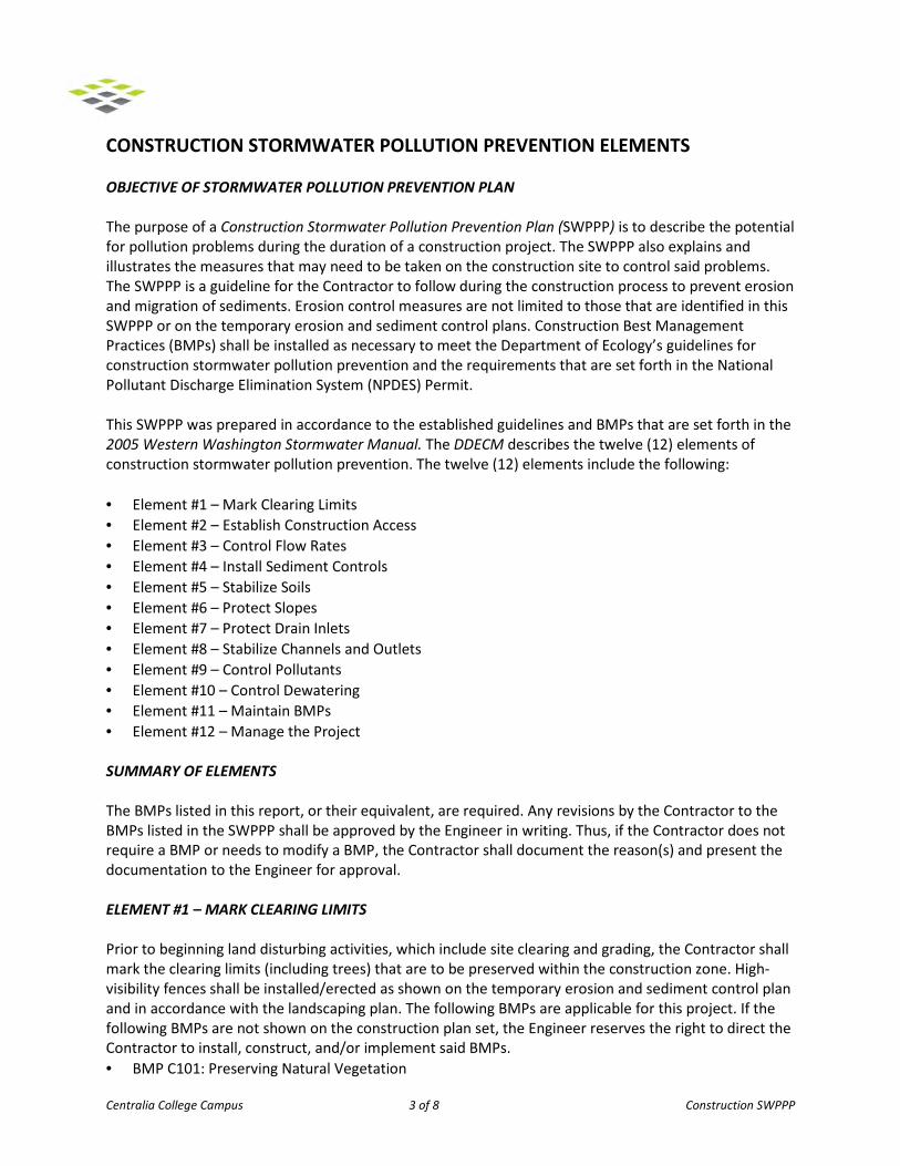
OBJECTIVE OF STORMWATER POLLUTION PREVENTION PLAN The purpose of a Construction Stormwater Pollution Prevention Plan (SWPPP) is to describe the potential for pollution problems during the duration of a construction project. The SWPPP also explains and illustrates the measures that may need to be taken on the construction site to control said problems. The SWPPP is a guideline for the Contractor to follow during the construction process to prevent erosion and migration of sediments. Erosion control measures are not limited to those that are identified in this SWPPP or on the temporary erosion and sediment control plans. Construction Best Management Practices (BMPs) shall be installed as necessary to meet the Department of Ecology’s guidelines for construction stormwater pollution prevention and the requirements that are set forth in the National Pollutant Discharge Elimination System (NPDES) Permit. This SWPPP was prepared in accordance to the established guidelines and BMPs that are set forth in the 2005 Western Washington Stormwater Manual. The DDECM describes the twelve (12) elements of construction stormwater pollution prevention. The twelve (12) elements include the following: • Element #1 – Mark Clearing Limits • Element #2 – Establish Construction Access • Element #3 – Control Flow Rates • Element #4 – Install Sediment Controls • Element #5 – Stabilize Soils • Element #6 – Protect Slopes • Element #7 – Protect Drain Inlets • Element #8 – Stabilize Channels and Outlets • Element #9 – Control Pollutants • Element #10 – Control Dewatering • Element #11 – Maintain BMPs • Element #12 – Manage the Project SUMMARY OF ELEMENTS
The BMPs listed in this report, or their equivalent, are required. Any revisions by the Contractor to the BMPs listed in the SWPPP shall be approved by the Engineer in writing. Thus, if the Contractor does not require a BMP or needs to modify a BMP, the Contractor shall document the reason(s) and present the documentation to the Engineer for approval. ELEMENT #1 – MARK CLEARING LIMITS Prior to beginning land disturbing activities, which include site clearing and grading, the Contractor shall mark the clearing limits (including trees) that are to be preserved within the construction zone. High-visibility fences shall be installed/erected as shown on the temporary erosion and sediment control plan and in accordance with the landscaping plan. The following BMPs are applicable for this project. If the following BMPs are not shown on the construction plan set, the Engineer reserves the right to direct the Contractor to install, construct, and/or implement said BMPs. • BMP C101: Preserving Natural Vegetation
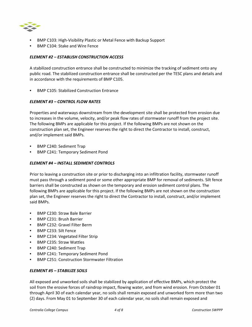
Centralia College Campus 4 of 8 Construction SWPPP
• BMP C103: High-Visibility Plastic or Metal Fence with Backup Support • BMP C104: Stake and Wire Fence ELEMENT #2 – ESTABLISH CONSTRUCTION ACCESS
A stabilized construction entrance shall be constructed to minimize the tracking of sediment onto any public road. The stabilized construction entrance shall be constructed per the TESC plans and details and in accordance with the requirements of BMP C105. • BMP C105: Stabilized Construction Entrance ELEMENT #3 – CONTROL FLOW RATES
Properties and waterways downstream from the development site shall be protected from erosion due to increases in the volume, velocity, and/or peak flow rates of stormwater runoff from the project site. The following BMPs are applicable for this project. If the following BMPs are not shown on the construction plan set, the Engineer reserves the right to direct the Contractor to install, construct, and/or implement said BMPs. • BMP C240: Sediment Trap
• BMP C241: Temporary Sediment Pond
ELEMENT #4 – INSTALL SEDIMENT CONTROLS
Prior to leaving a construction site or prior to discharging into an infiltration facility, stormwater runoff must pass through a sediment pond or some other appropriate BMP for removal of sediments. Silt fence barriers shall be constructed as shown on the temporary and erosion sediment control plans. The following BMPs are applicable for this project. If the following BMPs are not shown on the construction plan set, the Engineer reserves the right to direct the Contractor to install, construct, and/or implement said BMPs. • BMP C230: Straw Bale Barrier • BMP C231: Brush Barrier • BMP C232: Gravel Filter Berm • BMP C233: Silt Fence • BMP C234: Vegetated Filter Strip • BMP C235: Straw Wattles • BMP C240: Sediment Trap • BMP C241: Temporary Sediment Pond • BMP C251: Construction Stormwater Filtration ELEMENT #5 – STABILIZE SOILS
All exposed and unworked soils shall be stabilized by application of effective BMPs, which protect the soil from the erosive forces of raindrop impact, flowing water, and from wind erosion. From October 01 through April 30 of each calendar year, no soils shall remain exposed and unworked form more than two (2) days. From May 01 to September 30 of each calendar year, no soils shall remain exposed and
Centralia College Campus 5 of 8 Construction SWPPP
unworked for more than seven (7) days. This condition applies to all on-site soils, whether at final grade or not. In areas where the on-site soils will remain unworked for more than the aforementioned time duration limits or have reached final grade, seeding and mulching shall be installed in accordance with BMP C120 and C121. Sod shall be installed in accordance with BMP C124 for disturbed areas that require immediate vegetative cover. Dust control shall be used as needed to prevent wind transport of dust from disturbed soil surfaces and in accordance with BMP C140. If the following BMPs are not shown on the construction plan set, the Engineer reserves the right to direct the Contractor to install, construct, and/or implement said BMPs. BMP C120: Temporary and Permanent Seeding BMP C121: Mulching BMP C123: Plastic Covering BMP C124: Sodding BMP C125: Topsoiling BMP C140: Dust Control ELEMENT #6 – PROTECTING SLOPES
Slopes shall be constructed in such a manner that will minimize erosion. This shall include, but is not limited to: placing excavated material on the uphill side of trenches, collecting drainage at the top of slopes, etc. If the following BMPs are not shown on the construction plan set, the Engineer reserves the right to direct the Contractor to install, construct, and/or implement said BMPs. BMP C130: Surface Roughening BMP C200: Interceptor Dike and Swale BMP C205: Subsurface Drains BMP C207: Check Dams ELEMENT #7 – PROTECT DRAIN INLETS
All storm drain catch basins/inlets that are in use during construction, as well as all existing structures within the project limits, shall be protected so that stormwater runoff shall not enter any conveyance system without first being filtered or treated to remove sediment from sediment laden runoff. Install temporary catch basin filters as shown on the erosion and sediment control plans and in accordance with BMP C220. Inlets should be inspected weekly at a minimum and daily during storm events. Inlet protection devices should be cleaned or removed and replaced before six inches of sediment has accumulated BMP C220: Storm Drain Inlet Protection ELEMENT #8 – STABILIZE CHANNELS AND OUTLETS
All temporary on-site conveyance channels shall be constructed and stabilized to prevent erosion. Stabilization, including armoring material, adequate to prevent erosion of outlets, adjacent stream banks, slopes, and downstream reaches shall be provided at the outlets of all conveyance systems. If the
Centralia College Campus 6 of 8 Construction SWPPP
following BMPs are not shown on the construction plan set, the Engineer reserves the right to direct the Contractor to install, construct, and/or implement said BMPs. BMP C202: Channel Lining BMP C209: Outlet Protection ELEMENT #9 – CONTROL POLLUTANTS All pollutants, including waste materials and demolition of debris, that are generated or brought on-site during construction activities shall be handled and disposed of in a manner that does not cause contamination of stormwater. Maintenance and repair of heavy equipment and vehicles involving oil changes, hydraulic system drawdown, solvent and degreasing cleaning operations, fuel tank drawdown and removal, and other activities which may result in discharge or spillage of pollutants to the ground or into stormwater runoff must be conducted using spill prevention measures. Contaminated surfaces shall be cleaned immediately following any discharge or spill incident. Emergency repairs may be performed on-site using temporary plastic placed beneath and, if raining, over the vehicle. Application of agricultural chemicals, including fertilizers and pesticides, shall be conducted in a manner and at application rates that will not result in loss of chemical(s) to stormwater runoff. Manufacturers’ recommendations shall be followed for application rates and procedures. The following Source Control BMPs will be prepared/implemented by the Contractor for this project. • A Spill Prevention Plan • Maintenance of storm drainage facilities • Street sweeping at an interval that’s prescribed by the Engineer ELEMENT #10 – CONTROL DEWATERING
All foundation, vault, and trench dewatering activities shall be routed to a sediment pond for basic filtering/treatment. Clean, non-turbid dewatered water, as determined by the Certified Professional in Erosion and Sediment Control, can be discharged to systems tributary to state surface waters, provided the dewatering flow does not cause erosion or flooding to receiving waters. Highly turbid or otherwise contaminated dewatered water that’s from construction equipment operation, clamshell digging, concrete tremie pour, or work inside a cofferdam, shall be handled separately from stormwater at the site. Some disposal options, depending on site constraints, may include: • Transport off-site in a vehicle, such as a vacuum flush truck, for legal disposal in a manner that does
not pollute State waters • On-site treatment using chemical treatment or other suitable treatment technologies • Sanitary sewer discharge with local sewer district’s approval if there is no other option ELEMENT #11 – MAINTAIN BMPs
All temporary and permanent erosion and sediment control BMPs shall be maintained and repaired as needed to assure continued performance of their intended function. All maintenance and repairs shall be completed in accordance with the practices, procedures, and materials for each respective BMP.
Centralia College Campus 7 of 8 Construction SWPPP
Sediment Control BMPs shall be inspected weekly or after a runoff-producing storm event during the dry season and daily during the wet season. All temporary erosion and Sediment Control BMPs shall be removed within thirty (30) days after final site stabilization is achieved or after the temporary BMPs are no longer needed. Trapped sediment shall be removed or stabilized on-site. Disturbed soil areas resulting from removal of BMPs or vegetation shall be permanently stabilized. ELEMENT #12 – MANAGE THE PROJECT
• Phasing of Construction - the project shall be phased where feasible in order to prevent, to the maximum extent practicable, the transport of sediment from the site during construction. Revegetation of exposed areas and maintenance of said vegetation shall be an integral part of the clearing activities for each phase.
• Seasonal Work Limitations - from October 01 through April 30, clearing, grading, and other soil
disturbing activities shall only be permitted if shown to the satisfaction of the local permitting authority that silt-laden runoff will be prevented from leaving the construction site.
The following activities are exempt for the seasonal clearing and grading limitations: 1. Routine maintenance and necessary repair of erosion and sediment control BMPs.
2. Routine maintenance of public facilities or existing utility structures that do not expose the soil or result in the removal of the vegetative cover to the soil.
3. Activities where there is 100% infiltration of surface runoff within the site in approved and installed erosion and sediment control facilities.
• Inspection and Monitoring - all BMPs shall be inspected, maintained, and repaired as needed to assure continued performance of their intended function.
The Certified Professional in Erosion and Sediment Control for this project is ______________________________. ______________________________ shall be on-site or on-call at all times during construction. The role of the Certified Professional in Erosion and Sediment Control is to identify problems or failures of erosion control measures in the field and to promptly initiate corrective measures. The Certified Professional in Erosion and Sediment Control shall be compensated by the Contractor. Sampling and analysis of discharged stormwater from the construction site may be necessary to ensure compliance with the standards. Whenever inspection and/or monitoring reveals that the BMPs identified in the Construction SWPPP are inadequate, due to the actual discharge of or potential to discharge a significant amount of any pollutant, the Construction SWPPP shall be modified, as appropriate, in a timely manner.

Centralia College Campus 8 of 8 Construction SWPPP
• Maintenance of the Construction SWPPP - the Construction SWPPP shall be retained on-site or within reasonable access to the site. The Construction SWPPP shall be modified whenever there is a significant change in the design, construction, operation, and/or maintenance of any BMP.
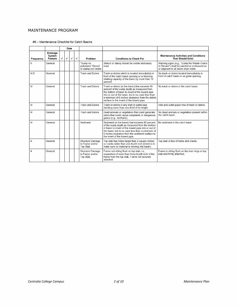
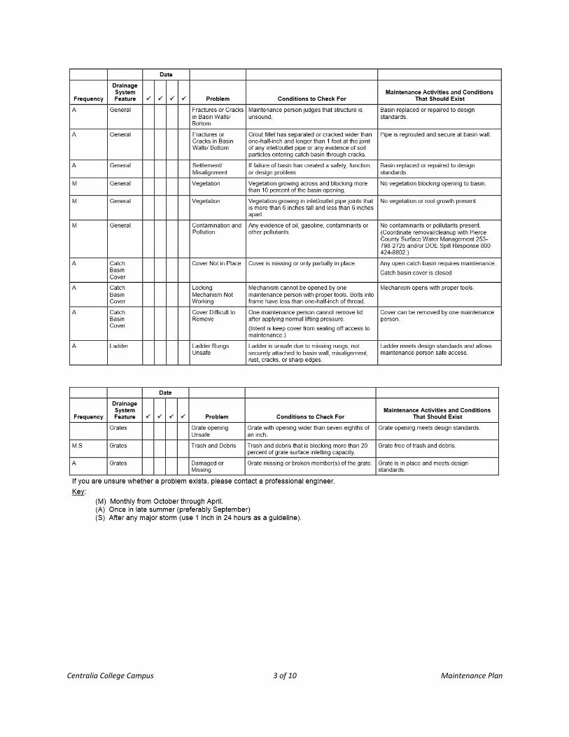
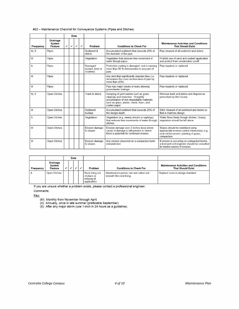
APPENDIX 7
MAINTENANCE PLAN
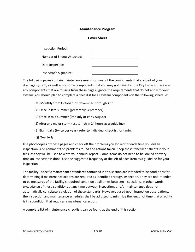
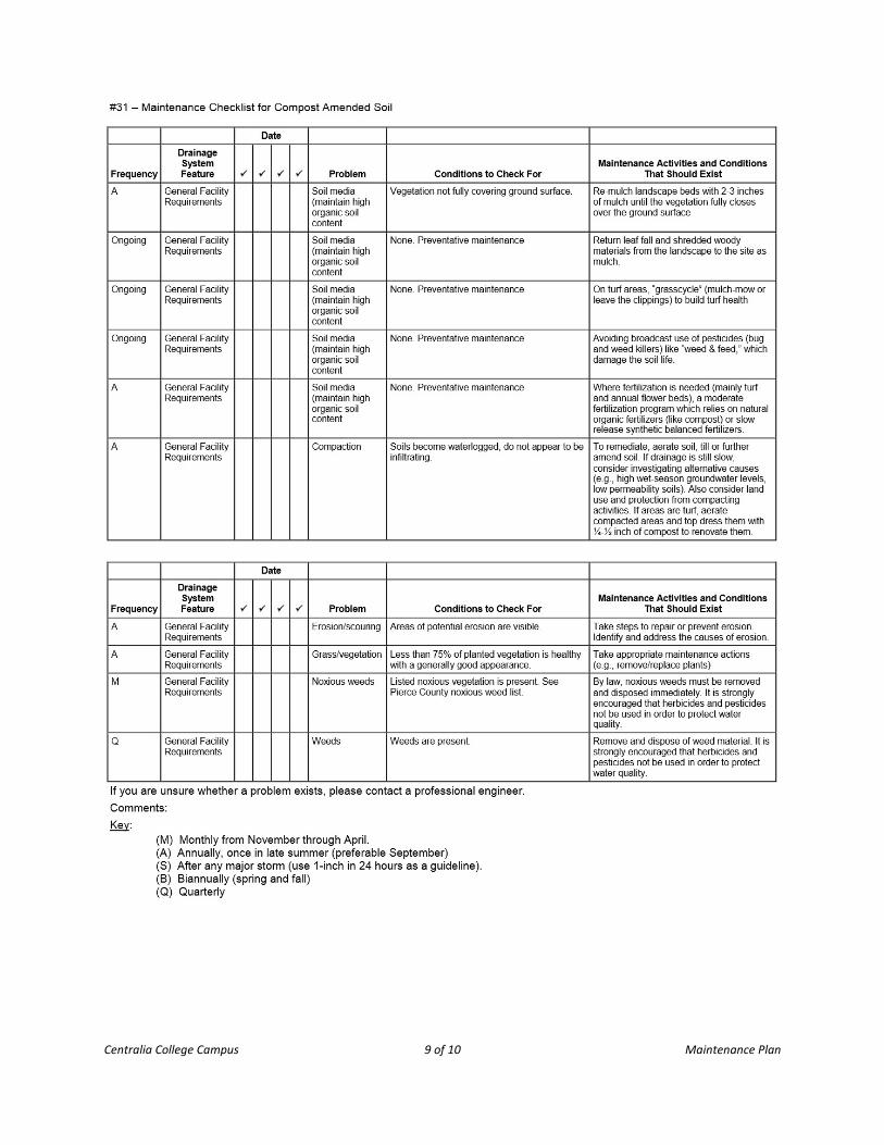
Centralia College Campus 1 of 10 Maintenance Plan
Maintenance Program
Cover Sheet
Inspection Period:
Number of Sheets Attached:
Date Inspected:
Inspector’s Signature:
The following pages contain maintenance needs for most of the components that are part of your drainage system, as well as for some components that you may not have. Let the City know if there are any components that are missing from these pages. Ignore the requirements that do not apply to your system. You should plan to complete a checklist for all system components on the following schedule:
(M) Monthly from October (or November) through April
(A) Once in late summer (preferably September)
(C) Once in mid summer (late July or early August)
(S) After any major storm (use 1 inch in 24 hours as a guideline)
(B) Biannually (twice per year - refer to individual checklist for timing)
(Q) Quarterly
Use photocopies of these pages and check off the problems you looked for each time you did an inspection. Add comments on problems found and actions taken. Keep these “checked" sheets in your files, as they will be used to write your annual report. Some items do not need to be looked at every time an inspection is done. Use the suggested frequency at the left of each item as a guideline for your inspection.
The facility - specific maintenance standards contained in this section are intended to be conditions for determining if maintenance actions are required as identified through inspection. They are not intended to be measures of the facility's required condition at all times between inspections. In other words, exceedance of these conditions at any time between inspections and/or maintenance does not automatically constitute a violation of these standards. However, based upon inspection observations, the inspection and maintenance schedules shall be adjusted to minimize the length of time that a facility is in a condition that requires a maintenance action.
A complete list of maintenance checklists can be found at the end of this section.
Centralia College Campus 2 of 10 Maintenance Plan
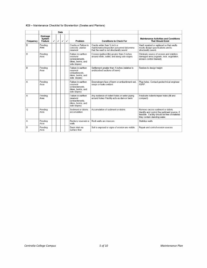
MAINTENANCE PROGRAM
Centralia College Campus 3 of 10 Maintenance Plan
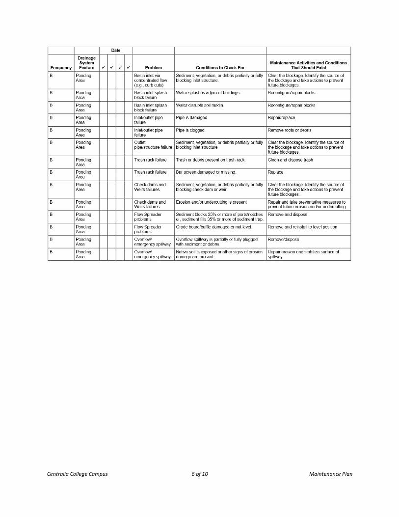
Centralia College Campus 4 of 10 Maintenance Plan
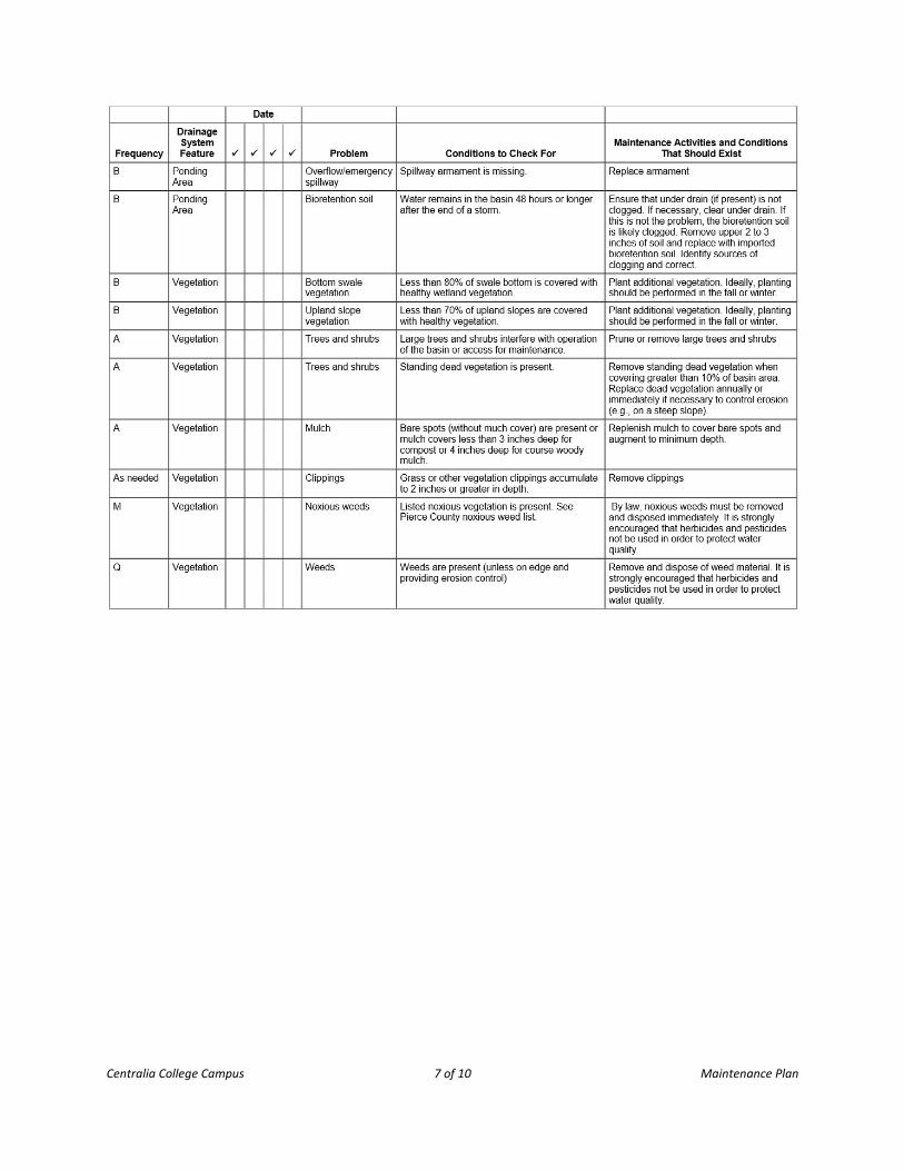
Centralia College Campus 5 of 10 Maintenance Plan
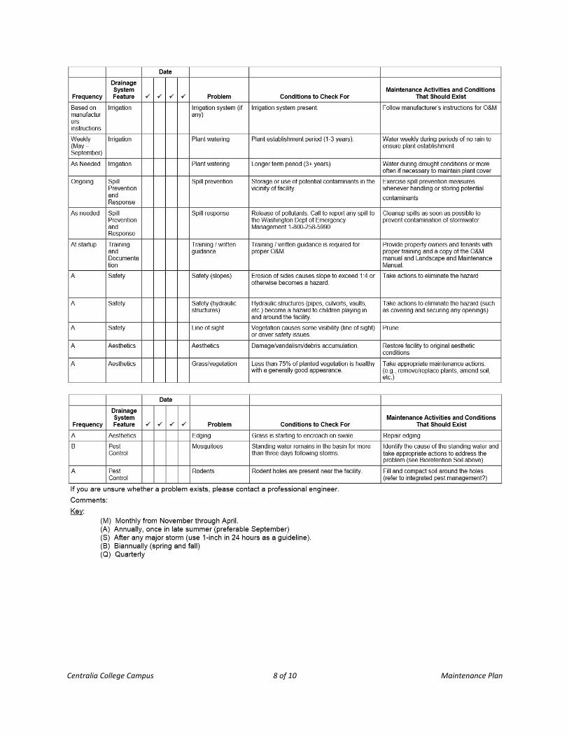
Centralia College Campus 6 of 10 Maintenance Plan
Centralia College Campus 7 of 10 Maintenance Plan
Centralia College Campus 8 of 10 Maintenance Plan
Centralia College Campus 9 of 10 Maintenance Plan
Centralia College Campus 10 of 10 Maintenance Plan
Maintenance covenants shall include the maintenance standards specified by the Department of Ecology's 2005 Stormwater Management Manual for Western Washington, Chapter 4, Volume V, a list of maintenance activities and proposed inspection intervals for each element of the private stormwater system, and a guarantee that any maintenance necessary for any element of the stormwater system will be performed to the standards specified by the Department of Ecology's 2005 Stormwater Management Manual for Western Washington, Chapter 4, Volume V and within the following schedule:
1. Within one year for wet pool facilities and retention/detention ponds;
2. Within six months for typical maintenance;
3. Within nine months for maintenance requiring re-vegetation;
4. Within two years for maintenance that requires capital construction of less than $25,000.
APPENDIX 8
GEOTECHNICAL REPORT
1015 East 4th Avenue, Olympia, Washington 98506 Phone: 360.754.2128 Fax: 360.754.9299
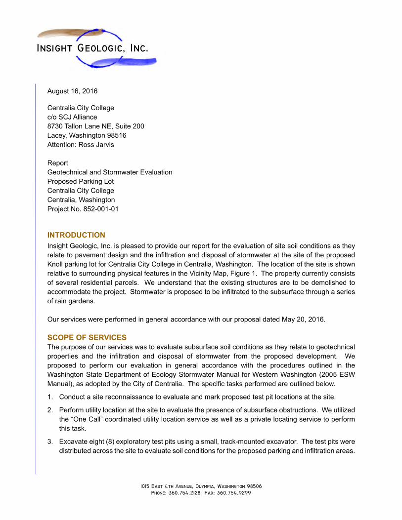
August 16, 2016 Centralia City College c/o SCJ Alliance 8730 Tallon Lane NE, Suite 200 Lacey, Washington 98516 Attention: Ross Jarvis Report Geotechnical and Stormwater Evaluation Proposed Parking Lot Centralia City College Centralia, Washington Project No. 852-001-01 INTRODUCTION Insight Geologic, Inc. is pleased to provide our report for the evaluation of site soil conditions as they relate to pavement design and the infiltration and disposal of stormwater at the site of the proposed Knoll parking lot for Centralia City College in Centralia, Washington. The location of the site is shown relative to surrounding physical features in the Vicinity Map, Figure 1. The property currently consists of several residential parcels. We understand that the existing structures are to be demolished to accommodate the project. Stormwater is proposed to be infiltrated to the subsurface through a series of rain gardens. Our services were performed in general accordance with our proposal dated May 20, 2016. SCOPE OF SERVICES The purpose of our services was to evaluate subsurface soil conditions as they relate to geotechnical properties and the infiltration and disposal of stormwater from the proposed development. We proposed to perform our evaluation in general accordance with the procedures outlined in the Washington State Department of Ecology Stormwater Manual for Western Washington (2005 ESW Manual), as adopted by the City of Centralia. The specific tasks performed are outlined below.
1. Conduct a site reconnaissance to evaluate and mark proposed test pit locations at the site.
2. Perform utility location at the site to evaluate the presence of subsurface obstructions. We utilized the “One Call” coordinated utility location service as well as a private locating service to perform this task.
3. Excavate eight (8) exploratory test pits using a small, track-mounted excavator. The test pits were distributed across the site to evaluate soil conditions for the proposed parking and infiltration areas.
Centralia City College Proposed Parking Lot Geotechnical and Stormwater Evaluation Report August 16, 2016
File No. 852−001−01 2
Insight Geologic, Inc.
The test pits were conducted to depths of between 7 and 8 feet below ground surface (bgs) and were backfilled at the end of the field day using the excavated soil.
4. Conduct appropriate laboratory testing on six (6) soil samples for grain-size distribution to determine stormwater infiltration rates.
5. Prepare a report to include a summary of our field activities, our findings, and recommendations for stormwater infiltration, site preparation and grading, seismic class, temporary and final cut slopes, earth pressures, paving design and suitability of the on-site soils for use as fill, along with our design infiltration rate for the site in accordance with the adopted City of Centralia Stormwater Manual (2005 ESW Manual).
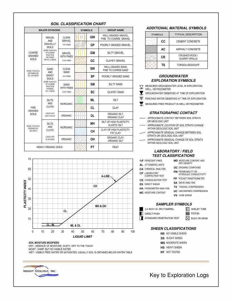
FINDINGS
Surface Conditions
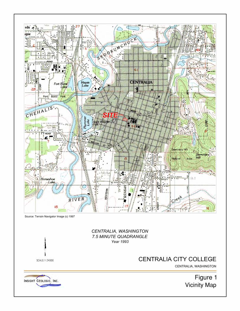
The project site is situated at an approximate elevation of 179 feet above mean sea level and is presently consists of six parcels. The combined project site is roughly rectangular in shape with an irregular northern boundary. The property is bounded by Centralia College Boulevard to the south, South Washington Avenue to the east, South King Street to the west, and mixed use commercial and residential properties to the north. The parcel is level and currently contains six single-family residences. Geology
Based on our review of available published geologic maps, Quaternary age alluvial deposits underlie the project site and surrounding area. This material is described as clay, silt, sand, and gravel, and locally peat and organic muck. This material was deposited as lacustrine and riparian over-bank deposits along the margins of the Chehalis River system.
Subsurface Explorations
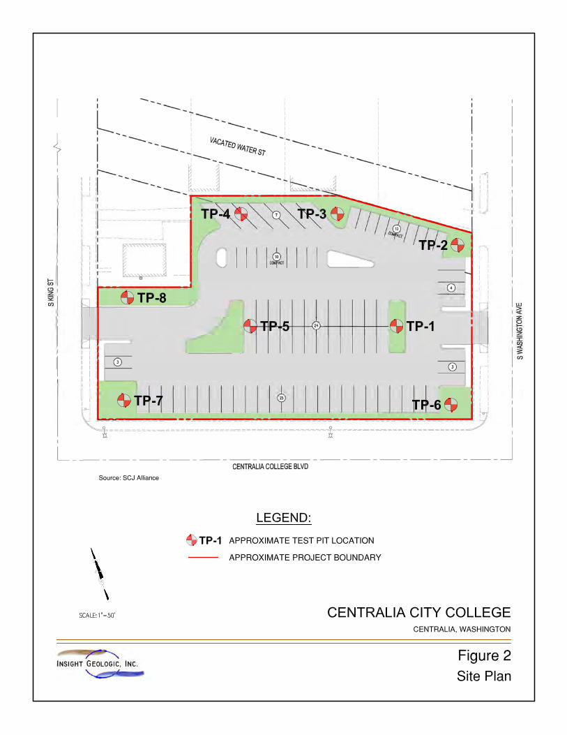
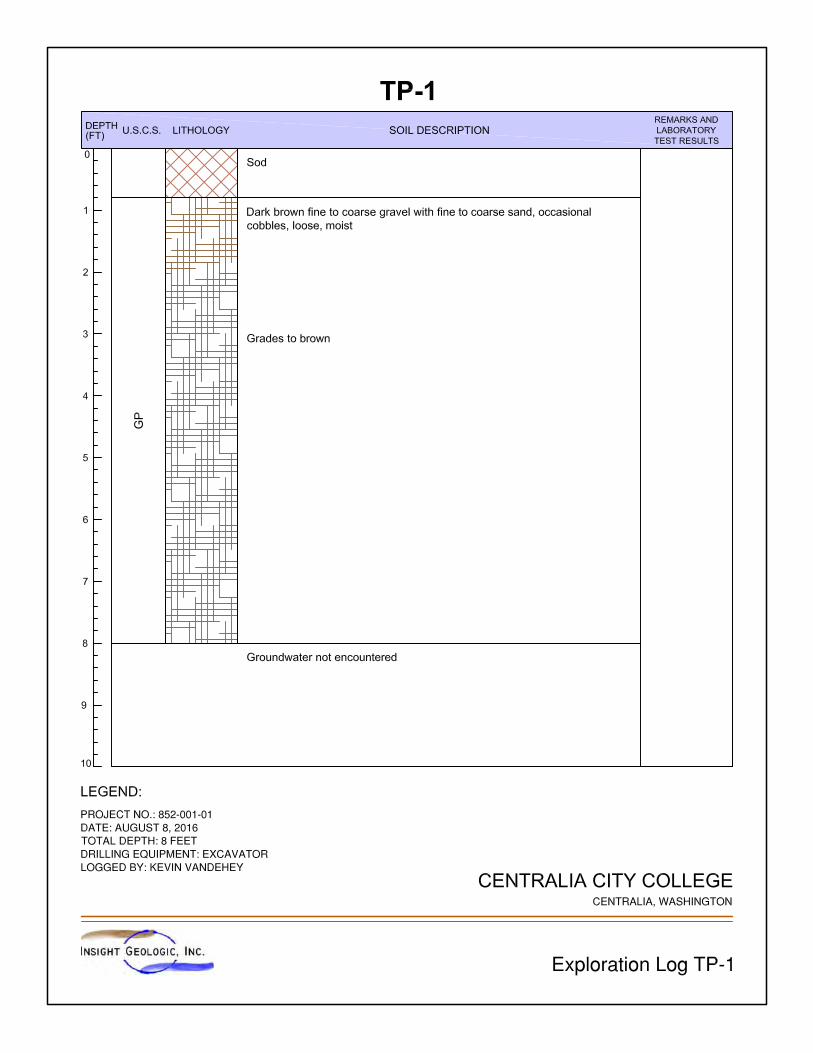
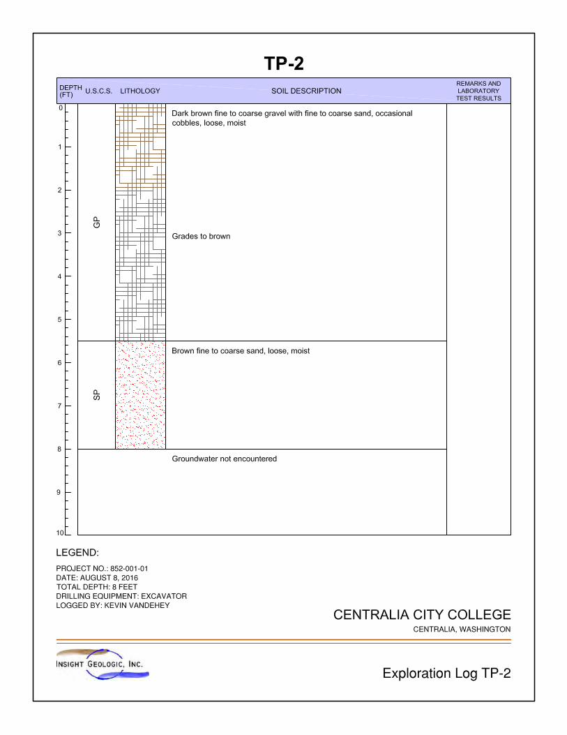
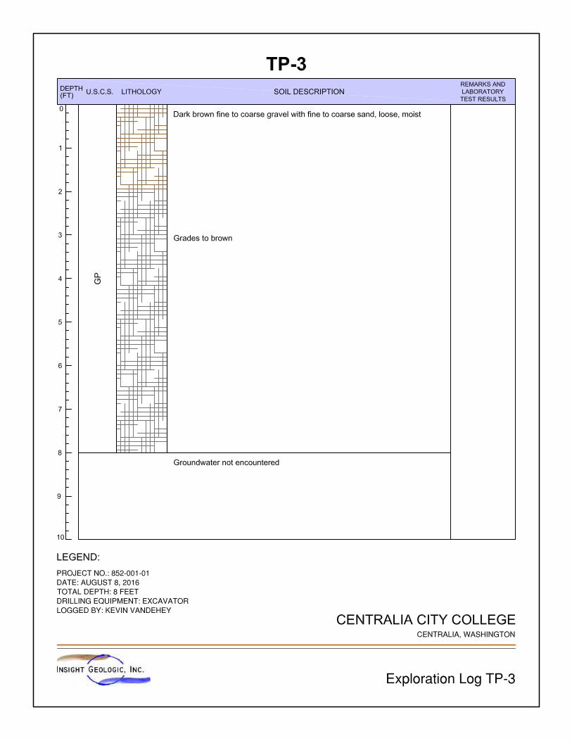
We explored subsurface conditions at the site on August 8, 2016 by excavating eight test pits in the locations as shown on the Site Plan, Figure 2. The test pits were excavated using a track-mounted excavator. A geologist from Insight Geologic monitored the test pits and maintained a log of the conditions encountered. The test pits were completed to the depth of 7 to 8 feet bgs. The soils were visually classified in general accordance with the system described in ASTM D2487-06. The explorations logs are contained in Attachment A.
Soil Conditions
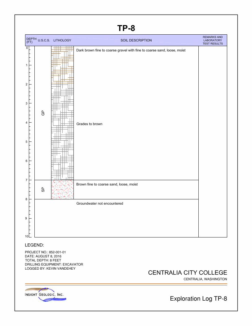
Soil conditions encountered were generally consistent with the mapped soils described in the Geology section above. We observed little variability in the soils between explorations. Our explorations generally encountered dark brown to brown poorly-graded gravel with sand and occasional cobbles (GP) in a loose and moist state, extending to the base of the test pits. Several exceptions to this general description were noted. Test pits TP-1, TP-4, TP-6 and TP-7 had between 0.5 and 1 foot of sod at the surface of the test pits. Test pits TP-2 and TP-8 encountered a unit of brown poorly-graded sand with gravel at depths of 5.5 and 7 feet bgs, respectively. Within test
Centralia City College Proposed Parking Lot Geotechnical and Stormwater Evaluation Report August 16, 2016
File No. 852−001−01 3
Insight Geologic, Inc.
pit TP-7, we encountered the greatest variability of soil units with 0.5 feet of sod, overlying 3.5 feet of poorly-graded sand with gravels (SP), which in turn was overlying 2 feet of well-graded gravel with sand (GW) before encountering the poorly-graded sand with gravel (GP) unit. The soils encountered are consistent with Spanaway gravely sandy loam, which is mapped for the area. These soils are generally formed from glacial outwash and in this area has a strongly contrasting textural change approximately 2 feet bgs. Percolation is generally high, with rates between 1.98 and 5.95 inches per hour, according to the U.S. Department of Agriculture Soil Survey. Groundwater Conditions
Groundwater was not encountered in any of the test pits completed at the site. In addition, no evidence of seasonal high groundwater was encountered. Laboratory Testing
We selected six soil samples for gradation analyses in general accordance with ASTM D422 to define soil class and obtain parameters for stormwater infiltration calculations. Our laboratory test results are provided in Attachment B. STORMWATER INFILTRATION
We completed a stormwater infiltration rate evaluation in general accordance with the Washington State Department of Ecology Stormwater Manual for Western Washington (2005 ESW Manual) Method 2, as adopted by the City of Centralia. For the purposes of this evaluation, we selected Method 2 “ASTM Gradation Testing at Full Scale Infiltration Facilities” to estimate the long-term design infiltration rates at the site. Method 2 “ASTM Gradation Testing at Full Scale Infiltration Facilities” is based on the D10 results of the ASTM grain-size distribution analyses to estimate long-term design infiltration rates. The Method 2 values are listed in Table 3.8 of Volume III of the 2005 ESW Manual. To better identify infiltration rates for soils having D10 values which lie between the values listed in the table, we have plotted those values graphically and calculated a best-fit line to the data. The equation for the best fit line is y = 23.3x – 0.5, where “y” is the infiltration rate in inches per hour and “x” is the D10 value as determined by the ASTM gradation testing. By substituting our D10 sample values for “x” in the equation, we are able to calculate design infiltration rates (Fdesign) for each analyzed sample. Based on our gradation analyses, we estimate that long-term design infiltration rates (Fdesign) is approximately 9.6 inches per hour, based on an average rate for the soils at the site. The results of our stormwater infiltration evaluation are presented in Table 1.
Table 1. Design Infiltration Rates – Method 2
Test Pit Unit Depth Range (feet) D10 Value Design Infiltration Rate
(inches per hour) TP-1 GP 3.0 – 7.0 0.70 15.8 TP-3 GP 3.0 – 8.0 0.59 13.2 TP-5 GP 0.0 – 4.0 0.28 6.0
TP-5 GP 4.0 – 7.0 0.55 12.3
TP-7 SP 0.5 – 4.0 0.16 3.2 TP-7 GW 4.0 – 6.0 0.32 7.0
Centralia City College Proposed Parking Lot Geotechnical and Stormwater Evaluation Report August 16, 2016
File No. 852−001−01 4
Insight Geologic, Inc.
Soil Liquefaction
Liquefaction refers to a condition where vibration or shaking of the ground, usually from earthquake forces, results in the development of excess pore water pressures in saturated soils, and a subsequent loss of stiffness in the soil occurs. Liquefaction also causes a temporary reduction of soil shear strength and bearing capacity, which can cause settlement of the ground surface above the liquefied soil layers. In general, soils that are most susceptible to liquefaction include loose to medium dense, clean to silty sands and non-plastic silts. Based on our review of the Liquefaction Susceptibility Map of Thurston County (Palmer, 2004), the project site is identified to have a moderate to high potential risk for soil liquefaction. Based on our experience with detailed seismic studies in the area, including areas that are mapped within the same soil deposits as the project site, we concur with the reviewed map. However, based on the planned site development, it is our opinion that the risk to significant damage to the facility is relatively low.
CONCLUSIONS AND RECOMMENDATIONS
General
Based on the results of our review, subsurface explorations and engineering analyses, it is our opinion that the proposed development is feasible from a geotechnical standpoint. We recommend that the proposed development can be designed using an allowable soil bearing capacity of 3,000 pounds per square foot (psf). The soils encountered in our explorations are typically in a loose condition near ground surface. To limit the potential for structure settlement, we recommend that subgrade and parking areas be established on a minimum 1-foot thick layer of structural fill. Depending on final grading plans and the time of year earthwork is performed; it could be practical to reuse the on-site soils as structural fill under the foundations/slab if properly compacted. Stormwater infiltration at the site is feasible. We have provided a design infiltration rate of 9.6 inches per hour for the proposed stormwater infiltration system. Our test pits were conducted during summer conditions and the lack of groundwater encountered should be reflective of typical summer seasonal conditions. Earthwork
General
We anticipate that site development earthwork will include clearing and stripping of existing vegetation, removal of existing structures, preparing subgrades, and placing and compacting structural fill. We expect that the majority of site grading can be accomplished with conventional earthmoving equipment in proper working order. Our explorations did not encounter appreciable amounts of debris or unsuitable soils associated with past site development with the exception of the existing structures slated for removal. Still, it is possible that concrete slabs, abandoned utility lines or other development features could be encountered during construction. The contractor should be prepared to deal with these conditions.
Centralia City College Proposed Parking Lot Geotechnical and Stormwater Evaluation Report August 16, 2016
File No. 852−001−01 5
Insight Geologic, Inc.
Clearing and Stripping
Clearing and stripping should consist of removing surface and subsurface deleterious materials including sod/topsoil, trees, brush, debris and other unsuitable loose/soft or organic materials. Stripping and clearing should extend at least 5 feet beyond all structures and areas to receive structural fill. We estimate that a stripping depth of about 0.5 feet were required to remove the vegetation encountered in our explorations. Deeper stripping depths may be required if additional unsuitable soils are exposed during stripping operations. Subgrade Preparation
After stripping and excavating to the proposed subgrade elevation, and before placing structural fill or foundation concrete, the exposed subgrade should be thoroughly compacted to a firm and unyielding condition. The exposed subgrade should then be proof-rolled using loaded, rubber-tired heavy equipment. We recommend that Insight Geologic be retained to observe the proof-rolling prior to placement of structural fill or foundation concrete. Areas of limited access that cannot be proof-rolled can be evaluated using a steel probe rod. If soft or otherwise unsuitable areas are revealed during proof-rolling or probing, that cannot be compacted to a stable and uniformly firm condition, we generally recommend that: 1) the subgrade soils be scarified (e.g., with a ripper or farmer’s disc), aerated and recompacted; or 2) the unsuitable soils be overexcavated and replaced with structural fill. Temporary Excavations and Groundwater Handling
Excavations deeper than 4 feet should be shored or laid back at a stable slope if workers are required to enter. Shoring and temporary slope inclinations must conform to the provisions of Title 296 Washington Administrative Code (WAC), Part N, “Excavation, Trenching and Shoring.” Regardless of the soil type encountered in the excavation, shoring, trench boxes or sloped sidewalls were required under the Washington Industrial Safety and Health Act (WISHA). The contract documents should specify that the contractor is responsible for selecting excavation and dewatering methods, monitoring the excavations for safety and providing shoring, as required, to protect personnel and structures. In general, temporary cut slopes should be inclined no steeper than about 1.5H:1V (horizontal: vertical). This guideline assumes that all surface loads are kept at a minimum distance of at least one-half the depth of the cut away from the top of the slope, and that significant seepage is not present on the slope face. Flatter cut slopes were necessary where significant seepage occurs or if large voids are created during excavation. Some sloughing and raveling of cut slopes should be expected. Temporary covering with heavy plastic sheeting should be used to protect slopes during periods of wet weather. We anticipate that if perched groundwater is encountered during construction can be handled adequately with sumps, pumps, and/or diversion ditches. Groundwater handling needs will generally be lower during the late summer and early fall months. We recommend that the contractor performing the work be made responsible for controlling and collecting groundwater encountered during construction.
Centralia City College Proposed Parking Lot Geotechnical and Stormwater Evaluation Report August 16, 2016
File No. 852−001−01 6
Insight Geologic, Inc.
Permanent Slopes
We do not anticipate that permanent slopes will be utilized for the proposed project. If permanent slopes are necessary, we recommend the slopes be constructed at a maximum inclination of 2H:1V. Where 2H:1V permanent slopes are not feasible, protective facings and/or retaining structures should be considered. To achieve uniform compaction, we recommend that fill slopes be overbuilt and subsequently cut back to expose well-compacted fill. Fill placement on slopes should be benched into the slope face and include keyways. The configuration of the bench and keyway depends on the equipment being used. Bench excavations should be level and extend into the slope face. We recommend that a vertical cut of about 3 feet be maintained for benched excavations. Keyways should be about 1-1/2 times the width of the equipment used for grading or compaction. Erosion Control
We anticipate that erosion control measures such as silt fences, straw bales and sand bags will generally be adequate during development. Temporary erosion control should be provided during construction activities and until permanent erosion control measures are functional. Surface water runoff should be properly contained and channeled using drainage ditches, berms, swales, and tightlines, and should not discharge onto sloped areas. Any disturbed sloped areas should be protected with a temporary covering until new vegetation can take effect. Jute or coconut fiber matting, excelsior matting or clear plastic sheeting is suitable for this purpose. Graded or disturbed slopes should be tracked in-place with the equipment running perpendicular to the slope contours so that the track marks provide a texture to help resist erosion. Ultimately, erosion control measures should be in accordance with local regulations and should be clearly described on project plans.
Wet Weather Earthwork
Some of the near surface soils contain up to about 4 percent fines. When the moisture content of the soil is more than a few percent above the optimum moisture content, the soil will become unstable and it may become difficult or impossible to meet the required compaction criteria. Disturbance of near surface soils should be expected if earthwork is completed during periods of wet weather. The wet weather season in this area generally begins in October and continues through May. However, periods of wet weather may occur during any month of the year. If wet weather earthwork is unavoidable, we recommend that:
The ground surface is sloped so that surface water is collected and directed away from the work area to an approved collection/dispersion point.
Earthwork activities not take place during periods of heavy precipitation.
Slopes with exposed soil be covered with plastic sheeting or otherwise protected from erosion.
Measures are taken to prevent on-site soil and soil stockpiles from becoming wet or unstable. Sealing the surficial soil by rolling with a smooth-drum roller prior to periods of precipitation should reduce the extent that the soil becomes wet or unstable.
Centralia City College Proposed Parking Lot Geotechnical and Stormwater Evaluation Report August 16, 2016
File No. 852−001−01 7
Insight Geologic, Inc.
Construction traffic is restricted to specific areas of the site, preferably areas that are surfaced with materials not susceptible to wet weather disturbance.
A minimum 1-foot thick layer of 4- to 6-inch quarry spalls is used in high traffic areas of the site to protect the subgrade soil from disturbance.
Contingencies are included in the project schedule and budget to allow for the above elements.
Structural Fill Materials
General
Material used for structural fill should be free of debris, organic material and rock fragments larger than 3 inches. The workability of material for use as structural fill will depend on the gradation and moisture content of the soil. As the amount of fines increases, soil becomes increasingly more sensitive to small changes in moisture content and adequate compaction becomes more difficult or impossible to achieve. On-Site Soil
We anticipate that the majority of the on-site soils encountered during construction will consist of the gravels and sands located at or near the surface of the site. It is our opinion that this material is a suitable source for structural fill during a significant portion of the year. On-site materials used as structural fill should be free of roots, organic matter and other deleterious materials and particles larger than 3 inches in diameter. Select Granular Fill
Select granular fill should consist of imported, well-graded sand and gravel or crushed rock with a maximum particle size of 3 inches and less than 5 percent passing a U.S. Standard No. 200 sieve based on the minus ¾-inch fraction. Organic matter, debris or other deleterious material should not be present. In our experience, “gravel borrow” as described in Section 9-03.14(1) of the 2008 WSDOT Standard Specifications is typically a suitable source for select granular fill during periods of wet weather, provided that the percent passing a U.S. Standard No. 200 sieve is less than 5 percent based on the minus ¾-inch fraction. Structural Fill Placement and Compaction
General
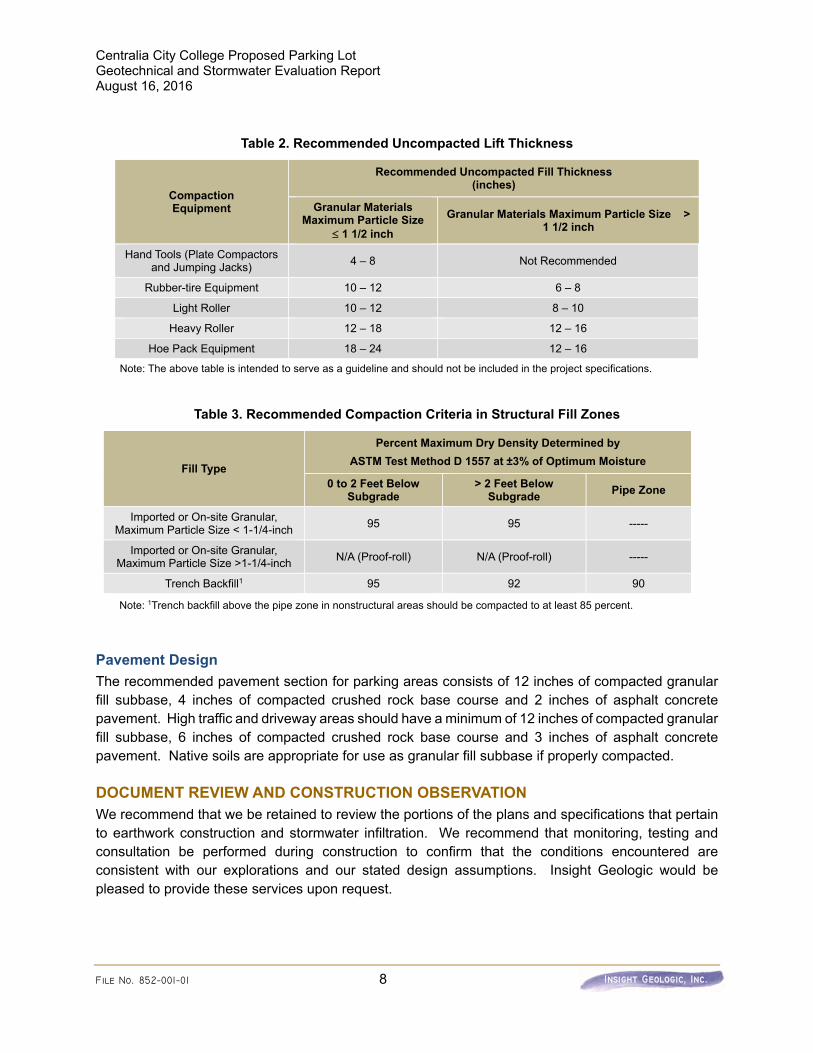
Structural fill should be placed on an approved subgrade that consists of uniformly firm and unyielding inorganic native soils or compacted structural fill. Structural fill should be compacted at a moisture content near optimum. The optimum moisture content varies with the soil gradation and should be evaluated during construction. Structural fill should be placed in uniform, horizontal lifts and uniformly densified with vibratory compaction equipment. The maximum lift thickness will vary depending on the material and compaction equipment used, but should generally not exceed the loose thicknesses provided on Table 2. Structural fill materials should be compacted in accordance with the compaction criteria provided in Table 3.
Centralia City College Proposed Parking Lot Geotechnical and Stormwater Evaluation Report August 16, 2016
File No. 852−001−01 8
Insight Geologic, Inc.
Table 2. Recommended Uncompacted Lift Thickness
Compaction Equipment
Recommended Uncompacted Fill Thickness (inches)
Granular Materials Maximum Particle Size
1 1/2 inch
Granular Materials Maximum Particle Size > 1 1/2 inch
Hand Tools (Plate Compactors and Jumping Jacks)
4 – 8 Not Recommended
Rubber-tire Equipment 10 – 12 6 – 8
Light Roller 10 – 12 8 – 10
Heavy Roller 12 – 18 12 – 16
Hoe Pack Equipment 18 – 24 12 – 16
Note: The above table is intended to serve as a guideline and should not be included in the project specifications.
Table 3. Recommended Compaction Criteria in Structural Fill Zones
Fill Type
Percent Maximum Dry Density Determined by
ASTM Test Method D 1557 at ±3% of Optimum Moisture
0 to 2 Feet Below Subgrade
> 2 Feet Below Subgrade
Pipe Zone
Imported or On-site Granular, Maximum Particle Size < 1-1/4-inch
95 95 -----
Imported or On-site Granular, Maximum Particle Size >1-1/4-inch
N/A (Proof-roll) N/A (Proof-roll) -----
Trench Backfill1 95 92 90
Note: 1Trench backfill above the pipe zone in nonstructural areas should be compacted to at least 85 percent.
Pavement Design
The recommended pavement section for parking areas consists of 12 inches of compacted granular fill subbase, 4 inches of compacted crushed rock base course and 2 inches of asphalt concrete pavement. High traffic and driveway areas should have a minimum of 12 inches of compacted granular fill subbase, 6 inches of compacted crushed rock base course and 3 inches of asphalt concrete pavement. Native soils are appropriate for use as granular fill subbase if properly compacted. DOCUMENT REVIEW AND CONSTRUCTION OBSERVATION
We recommend that we be retained to review the portions of the plans and specifications that pertain to earthwork construction and stormwater infiltration. We recommend that monitoring, testing and consultation be performed during construction to confirm that the conditions encountered are consistent with our explorations and our stated design assumptions. Insight Geologic would be pleased to provide these services upon request.
Centralia City College Proposed Parking Lot Geotechnical and Stormwater Evaluation Report August 16, 2016
File No. 852−001−01 9
Insight Geologic, Inc.
LIMITATIONS
We have prepared this geotechnical and stormwater evaluation report for the exclusive use of Centralia City College and their authorized agents for the Centralia City College proposed parking lot project in Centralia, Washington. Within the limitations of scope, schedule and budget, our services have been executed in accordance with generally accepted practices in the field of geotechnical engineering in this area at the time this report was prepared. No warranty or other conditions, expressed or implied, should be understood. Please refer to Attachment C titled “Report Limitations and Guidelines for Use” for additional information pertaining to use of this report.
_____________
_____________
Centralia City College Proposed Parking Lot Geotechnical and Stormwater Evaluation Report August 16, 2016
File No. 852−001−01 10
Insight Geologic, Inc.
We appreciate the opportunity to be of service to you on this project. Please contact us if you have questions or require additional information. Respectfully Submitted, Insight Geologic, Inc.
William E. Halbert, L.E.G., L.HG. Principal Attachments

Insight Geologic, Inc.
FIGURES
Insight Geologic, Inc.
ATTACHMENT A
EXPLORATION LOGS
Insight Geologic, Inc.
ATTACHMENT B
LABORATORY ANALYSES RESULTS

Job Name: Centralia City College Sample Location: TP-1Job Number: 852-001-01 Sample Name: TP-1 3.0'-8.0'Date Tested: 8/10/16 Depth: 3 - 8 Feet
Tested By: Kevin Vandehey
5.3%
Percent Percent bySieve Size Passing Size Fraction Weight
3.0 in. (75.0) 100.0 Coarse Gravel 35.91.5 in. (37.5) 100.0 Fine Gravel 25.93/4 in. (19.0) 64.13/8 in. (9.5-mm) 47.2 Coarse Sand 7.9No. 4 (4.75-mm) 38.3 Medium Sand 26.7No. 10 (2.00-mm) 30.3 Fine Sand 2.8No. 20 (.850-mm) 13.2No. 40 (.425-mm) 3.7 Fines 0.9No. 60 (.250-mm) 1.9 Total 100.0No. 100 (.150-mm) 1.3No. 200 (.075-mm) 0.9
LL - -PL - -Pl - -
D10 0.70D30 2.00D60 17.00D90 32.00
Cc 0.34Cu 24.29
ASTM ClassificationGroup Name: Poorly-Graded Gravel with Sand
Symbol: GP
Gradation Analysis Summary Data
Moisture Content (%)

Job Name: Centralia City College Sample Location: TP-3Job Number: 852-001-01 Sample Name: TP-3 3.0'-8.0'Date Tested: 8/10/16 Depth: 3 - 8 Feet
Tested By: Kevin Vandehey
4.6%
Percent Percent bySieve Size Passing Size Fraction Weight
3.0 in. (75.0) 100.0 Coarse Gravel 32.41.5 in. (37.5) 91.0 Fine Gravel 26.03/4 in. (19.0) 67.63/8 in. (9.5-mm) 50.6 Coarse Sand 9.1No. 4 (4.75-mm) 41.6 Medium Sand 26.9No. 10 (2.00-mm) 32.5 Fine Sand 4.5No. 20 (.850-mm) 17.4No. 40 (.425-mm) 5.6 Fines 1.1No. 60 (.250-mm) 2.8 Total 100.0No. 100 (.150-mm) 1.9No. 200 (.075-mm) 1.1
LL - -PL - -Pl - -
D10 0.59D30 1.80D60 15.0D90 37.0
Cc 0.4Cu 25.4
ASTM ClassificationGroup Name: Poorly-Graded Gravel with Sand
Symbol: GP
Gradation Analysis Summary Data
Moisture Content (%)

Job Name: Centralia City College Sample Location: TP-5Job Number: 852-001-01 Sample Name: TP-5 0.0'-4.0'Date Tested: 8/10/16 Depth: 0 - 4 Feet
Tested By: Kevin Vandehey
6.0%
Percent Percent bySieve Size Passing Size Fraction Weight
3.0 in. (75.0) 100.0 Coarse Gravel 33.81.5 in. (37.5) 100.0 Fine Gravel 24.13/4 in. (19.0) 66.23/8 in. (9.5-mm) 51.1 Coarse Sand 6.9No. 4 (4.75-mm) 42.1 Medium Sand 20.8No. 10 (2.00-mm) 35.2 Fine Sand 11.0No. 20 (.850-mm) 23.3No. 40 (.425-mm) 14.4 Fines 3.4No. 60 (.250-mm) 9.5 Total 100.0No. 100 (.150-mm) 6.2No. 200 (.075-mm) 3.4
LL - -PL - -Pl - -
D10 0.28D30 1.40D60 17.00D90 32.00
Cc 0.41Cu 60.71
ASTM ClassificationGroup Name: Poorly-Graded Gravel with Sand
Symbol: GP
Moisture Content (%)
Gradation Analysis Summary Data
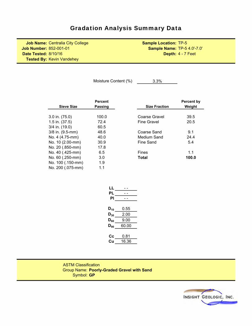
Job Name: Centralia City College Sample Location: TP-5Job Number: 852-001-01 Sample Name: TP-5 4.0'-7.0'Date Tested: 8/10/16 Depth: 4 - 7 Feet
Tested By: Kevin Vandehey
3.3%
Percent Percent bySieve Size Passing Size Fraction Weight
3.0 in. (75.0) 100.0 Coarse Gravel 39.51.5 in. (37.5) 72.4 Fine Gravel 20.53/4 in. (19.0) 60.53/8 in. (9.5-mm) 48.6 Coarse Sand 9.1No. 4 (4.75-mm) 40.0 Medium Sand 24.4No. 10 (2.00-mm) 30.9 Fine Sand 5.4No. 20 (.850-mm) 17.8No. 40 (.425-mm) 6.5 Fines 1.1No. 60 (.250-mm) 3.0 Total 100.0No. 100 (.150-mm) 1.9No. 200 (.075-mm) 1.1
LL - -PL - -Pl - -
D10 0.55D30 2.00D60 9.00D90 60.00
Cc 0.81Cu 16.36
ASTM ClassificationGroup Name: Poorly-Graded Gravel with Sand
Symbol: GP
Gradation Analysis Summary Data
Moisture Content (%)

Job Name: Centralia City College Sample Location: TP-7Job Number: 852-001-01 Sample Name: TP-7 0.5'-4.0'Date Tested: 8/10/16 Depth: 0.5 - 4 Feet
Tested By: Kevin Vandehey
5.9%
Percent Percent bySieve Size Passing Size Fraction Weight
3.0 in. (75.0) 100.0 Coarse Gravel 19.81.5 in. (37.5) 100.0 Fine Gravel 24.33/4 in. (19.0) 80.23/8 in. (9.5-mm) 63.6 Coarse Sand 6.0No. 4 (4.75-mm) 55.9 Medium Sand 25.6No. 10 (2.00-mm) 49.9 Fine Sand 20.4No. 20 (.850-mm) 35.3No. 40 (.425-mm) 24.3 Fines 3.9No. 60 (.250-mm) 15.9 Total 100.0No. 100 (.150-mm) 9.4No. 200 (.075-mm) 3.9
LL - -PL - -Pl - -
D10 0.16D30 0.61D60 7.50D90 27.00
Cc 0.31Cu 46.88
ASTM ClassificationGroup Name: Poorly-Graded Sand with Gravel
Symbol: SP
Moisture Content (%)
Gradation Analysis Summary Data

Job Name: Centralia City College Sample Location: TP-7Job Number: 852-001-01 Sample Name: TP-7 4.0'-6.0'Date Tested: 8/10/16 Depth: 4 - 6 Feet
Tested By: Kevin Vandehey
2.3%
Percent Percent bySieve Size Passing Size Fraction Weight
3.0 in. (75.0) 100.0 Coarse Gravel 61.11.5 in. (37.5) 77.8 Fine Gravel 8.13/4 in. (19.0) 38.93/8 in. (9.5-mm) 32.9 Coarse Sand 3.1No. 4 (4.75-mm) 30.8 Medium Sand 15.1No. 10 (2.00-mm) 27.7 Fine Sand 10.6No. 20 (.850-mm) 20.4No. 40 (.425-mm) 12.6 Fines 1.9No. 60 (.250-mm) 6.9 Total 100.0No. 100 (.150-mm) 3.9No. 200 (.075-mm) 1.9
LL - -PL - -Pl - -
D10 0.32D30 3.60D60 28.00D90 55.00
Cc 1.45Cu 87.50
ASTM ClassificationGroup Name: Well-Graded Gravel with Sand
Symbol: GW
Moisture Content (%)
Gradation Analysis Summary Data
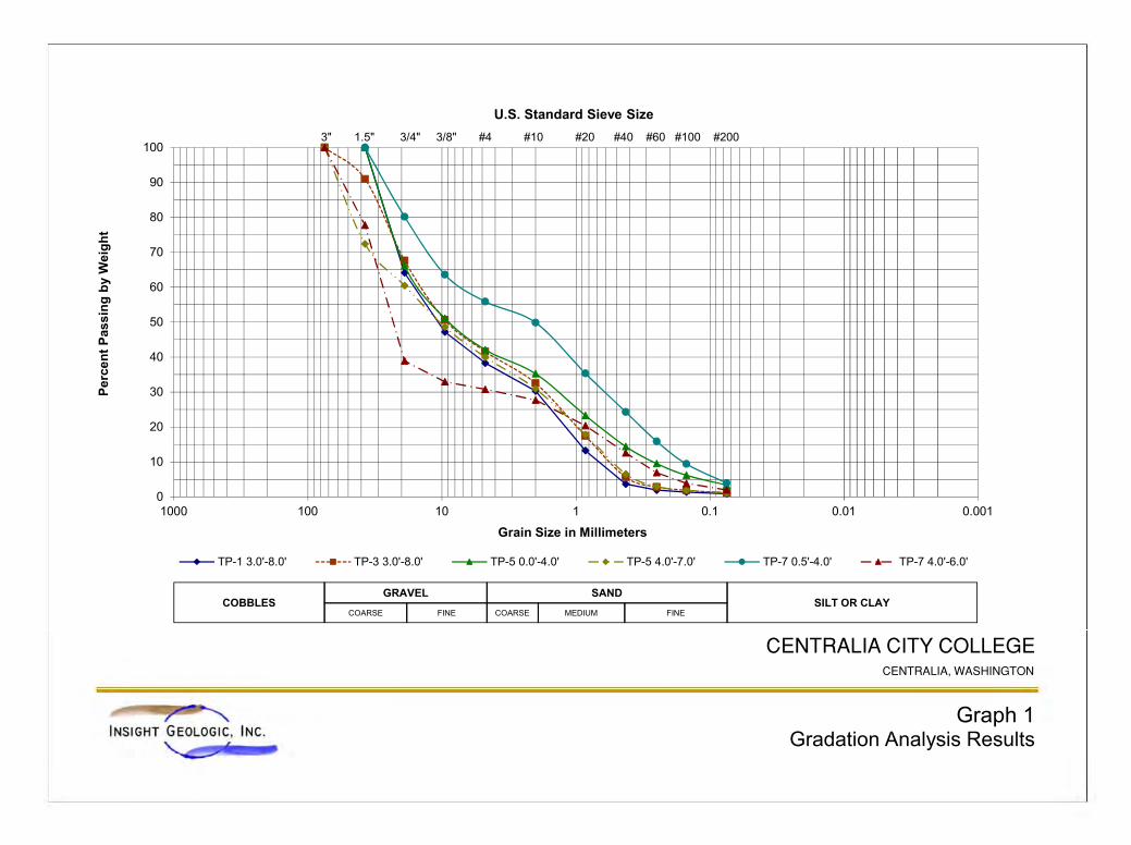
0
10
20
30
40
50
60
70
80
90
100
0.0010.010.11101001000
Per
cen
t P
assi
ng
by
Wei
gh
t
Grain Size in Millimeters
U.S. Standard Sieve Size
TP-1 3.0'-8.0' TP-3 3.0'-8.0' TP-5 0.0'-4.0' TP-5 4.0'-7.0' TP-7 0.5'-4.0' TP-7 4.0'-6.0'
COBBLESGRAVEL
SILT OR CLAYSAND
COARSE MEDIUM FINECOARSE FINE
3" 1.5" 3/4" 3/8" #4 #10 #20 #40 #60 #100 #200
Graph 1Gradation Analysis Results
CENTRALIA CITY COLLEGE CENTRALIA, WASHINGTON
Insight Geologic, Inc.
ATTACHMENT C
REPORT LIMITATIONS AND GUIDELINES FOR USE
I n s i g h t G e o l o g i c , I n c . L i m i t a t i o n s
ATTACHMENT C
REPORT LIMITATIONS AND GUIDELINES FOR USE1 This attachment provides information to help you manage your risks with respect to the use of this report. HYDROGEOLOGIC SERVICES ARE PERFORMED FOR SPECIFIC PURPOSES, PERSONS AND PROJECTS
This report has been prepared for the exclusive use of Centralia City College (Client) and their authorized agents. This report may be made available to regulatory agencies for review. This report is not intended for use by others, and the information contained herein is not applicable to other sites. Insight Geologic structures our services to meet the specific needs of our clients. For example, a hydrogeologic or geologic study conducted for a civil engineer or architect may not fulfill the needs of a construction contractor or even another civil engineer or architect that are involved in the same project. Because each hydrogeologic or geologic study is unique, each hydrogeologic or geologic report is unique, prepared solely for the specific client and project site. Our report is prepared for the exclusive use of our Client. No other party may rely on the product of our services unless we agree in advance to such reliance in writing. This is to provide our firm with reasonable protection against open-ended liability claims by third parties with whom there would otherwise be no contractual limits to their actions. Within the limitations of scope, schedule and budget, our services have been executed in accordance with our Agreement with the Client and generally accepted hydrogeologic practices in this area at the time this report was prepared. This report should not be applied for any purpose or project except the one originally contemplated. A HYDROGEOLOGIC OR GEOLOGIC REPORT IS BASED ON A UNIQUE SET OF PROJECT-SPECIFIC FACTORS
Insight Geologic considered a number of unique, project-specific factors when establishing the scope of services for this project and report. Unless Insight Geologic specifically indicates otherwise, do not rely on this report if it was:
not prepared for you,
not prepared for your project,
not prepared for the specific site explored, or
completed before important project changes were made.
If important changes are made after the date of this report, Insight Geologic should be given the opportunity to review our interpretations and recommendations and provide written modifications or confirmation, as appropriate.
SUBSURFACE CONDITIONS CAN CHANGE
This hydrogeologic or geologic report is based on conditions that existed at the time the study was performed. The findings and conclusions of this report may be affected by the passage of time, by
1 Developed based on material provided by ASFE, Professional Firms Practicing in the Geosciences; www.asfe.org .
I n s i g h t G e o l o g i c , I n c . L i m i t a t i o n s
manmade events such as construction on or adjacent to the site, or by natural events such as floods, earthquakes, slope instability or ground water fluctuations. Always contact Insight Geologic before applying a report to determine if it remains applicable. MOST HYDROGEOLOGIC AND GEOLOGIC FINDINGS ARE PROFESSIONAL OPINIONS
Our interpretations of subsurface conditions are based on field observations from widely spaced sampling locations at the site. Site exploration identifies subsurface conditions only at those points where subsurface tests are conducted or samples are taken. Insight Geologic reviewed field and laboratory data and then applied our professional judgment to render an opinion about subsurface conditions throughout the site. Actual subsurface conditions may differ, sometimes significantly, from those indicated in this report. Our report, conclusions and interpretations should not be construed as a warranty of the subsurface conditions. HYDROGEOLOGIC REPORT RECOMMENDATIONS ARE NOT FINAL
Do not over-rely on the preliminary recommendations included in this report. These recommendations are not final, because they were developed principally from Insight Geologic’s professional judgment and opinion. Insight Geologic’s recommendations can be finalized only by observing actual subsurface conditions revealed during construction. A HYDROGEOLOGIC OR GEOLOGIC REPORT COULD BE SUBJECT TO MISINTERPRETATION
Misinterpretation of this report by other design team members can result in costly problems. You could lower that risk by having Insight Geologic confer with appropriate members of the design team after submitting the report. Also retain Insight Geologic to review pertinent elements of the design team's plans and specifications. Contractors can also misinterpret a hydrogeologic engineering or geologic report. Reduce that risk by having Insight Geologic participate in pre-bid and preconstruction conferences, and by providing construction observation. DO NOT REDRAW THE EXPLORATION LOGS
Hydrogeologic engineers and geologists prepare final boring and test pit logs based upon their interpretation of field logs and laboratory data. To prevent errors or omissions, the logs included in a hydrogeologic engineering or geologic report should never be redrawn for inclusion in architectural or other design drawings. Only photographic or electronic reproduction is acceptable, but recognize that separating logs from the report can elevate risk. READ THESE PROVISIONS CLOSELY
Some clients, design professionals and contractors may not recognize that the geoscience practices (hydrogeologic engineering or geology) are far less exact than other engineering and natural science disciplines. This lack of understanding can create unrealistic expectations that could lead to disappointments, claims and disputes. Insight Geologic includes these explanatory “limitations” provisions in our reports to help reduce such risks. Please confer with Insight Geologic if you are unclear how these “Report Limitations and Guidelines for Use” apply to your project or site.

I n s i g h t G e o l o g i c , I n c . L i m i t a t i o n s
HYDROGEOLOGIC, GEOLOGIC AND ENVIRONMENTAL REPORTS SHOULD NOT BE INTERCHANGED
The equipment, techniques and personnel used to perform an environmental study differ significantly from those used to perform a hydrogeologic or geologic study and vice versa. For that reason, a hydrogeologic engineering or geologic report does not usually relate any environmental findings, conclusions or recommendations; e.g., about the likelihood of encountering underground storage tanks or regulated contaminants. Similarly, environmental reports are not used to address hydrogeologic or geologic concerns regarding a specific project.
APPENDIX 9
FEMA FLOOD INSURANCE RATE MAP
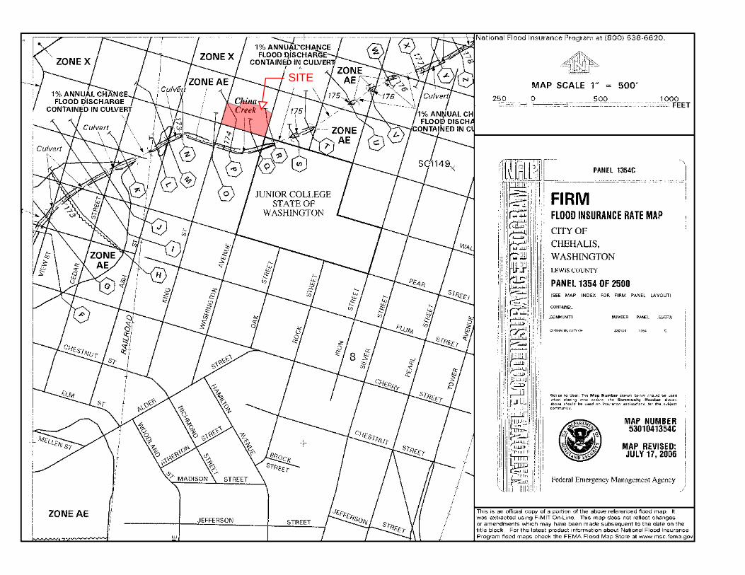
SITE