Embed Size (px)
Citation preview

Thurston County Drainage Design and Erosion Control
Manual
Volume I Core Technical Requirements
and Site Planning
Prepared by Thurston County Water Resources Division,
Department of Resource Stewardship
December 2016

This page intentionally left blank

THURSTON COUNTY DRAINAGE DESIGN AND EROSION CONTROL MANUAL
December 2016 Volume I – Minimum Technical Requirements i
Table of Contents Introduction ................................................................................................ 1-1
1.1 Volume I Overview...................................................................................................... 1-1 1.2 Development of Best Management Practices for Stormwater Management ............... 1-1
1.2.1 Best Management Practices (BMPs) .......................................................... 1-1 1.2.2 Source Control BMPs ................................................................................. 1-2 1.2.3 Treatment BMPs ......................................................................................... 1-2 1.2.4 Flow Control BMPs .................................................................................... 1-2 1.2.5 Construction Stormwater BMPs and On-Site Stormwater Management
BMPs........................................................................................................... 1-3
Core Requirements for New Development and Redevelopment ........... 2-1
2.1 Overview ...................................................................................................................... 2-1 2.1.1 Roadway Frontage Improvements .............................................................. 2-2 2.1.2 Cumulative Impact Mitigation Requirement .............................................. 2-3
2.2 Exemptions .................................................................................................................. 2-3 2.2.1 Forest Practices ........................................................................................... 2-3 2.2.2 Commercial Agriculture ............................................................................. 2-3 2.2.3 Pavement Maintenance Practices ................................................................ 2-3 2.2.4 Underground Utility Projects ...................................................................... 2-4 2.2.5 Public Drainage Facilities ........................................................................... 2-4
2.3 Applying Core Requirements ...................................................................................... 2-5 2.3.1 New Development ...................................................................................... 2-8 2.3.2 Redevelopment ......................................................................................... 2-10 2.3.3 Basin Planning .......................................................................................... 2-12
2.4 Core Requirements..................................................................................................... 2-13 2.4.1 About Threshold Discharge Areas ............................................................ 2-13 2.4.2 Core Requirement #1: Stormwater Site Planning .................................... 2-13 2.4.3 Core Requirement #2: Construction Stormwater Pollution Prevention
Plan (SWPPP) ........................................................................................... 2-14 2.4.4 Core Requirement #3: Source Control of Pollution ................................. 2-16 2.4.5 Core Requirement #4: Preservation of Natural Drainage Systems and
Outfalls ...................................................................................................... 2-17 2.4.6 Core Requirement #5: Onsite Stormwater Management ......................... 2-18 2.4.7 Core Requirement #6: Runoff Treatment ................................................ 2-25 2.4.8 Core Requirement #7: Flow Control........................................................ 2-27 2.4.9 Core Requirement #8: Wetlands Protection ............................................ 2-30 2.4.10 Core Requirement #9: Operation and Maintenance ................................. 2-31 2.4.11 Core Requirement #10: Financial Liability ............................................. 2-33 2.4.12 Core Requirement #11: Offsite Analysis and Mitigation ........................ 2-34
2.5 Deeds and Easements ................................................................................................. 2-36 2.6 Acceptance of New Stormwater Facilities ................................................................. 2-37
2.6.1 Public Ownership ...................................................................................... 2-37
THURSTON COUNTY DRAINAGE DESIGN AND EROSION CONTROL MANUAL
December 2016 Volume I – Minimum Technical Requirements ii
2.6.2 Private Ownership – Subdivision Projects ................................................ 2-37 2.6.3 Private Ownership – Other Projects .......................................................... 2-38
2.7 Adjustments ............................................................................................................... 2-38 2.8 Exceptions/Variances ................................................................................................. 2-38
2.8.1 Exceptions/Variances to Core Requirements............................................ 2-38 2.8.2 Variances/Exceptions from Design Standards, Submittal
Requirements, etc. ..................................................................................... 2-39 2.8.3 Supplemental Guidelines .......................................................................... 2-40
2.9 Interpretations and Appeals ....................................................................................... 2-40 2.10 Severability ................................................................................................................ 2-40
Stormwater Submittal Requirements ...................................................... 3-1
3.1 Introduction .................................................................................................................. 3-1 3.1.1 Site Characterization ................................................................................... 3-1 3.1.2 Site Design – Smart Design and Low Impact Development ...................... 3-4
3.2 Submittal Review and Acceptance Process ................................................................. 3-4 3.2.1 Presubmittal Meeting .................................................................................. 3-6 3.2.2 Preliminary Report Submittal ..................................................................... 3-7 3.2.3 Final Report Submittal ................................................................................ 3-7 3.2.4 Final Report Acceptance ............................................................................. 3-7 3.2.5 Final Project Acceptance ............................................................................ 3-8
3.3 Submittal Format ......................................................................................................... 3-8 3.4 Submittal Types ........................................................................................................... 3-9
3.4.1 Projects Exempt from Submittal Requirements ........................................ 3-12 3.4.2 Abbreviated Drainage Plan ....................................................................... 3-12 3.4.3 Engineered Abbreviated Drainage Plan .................................................... 3-14 3.4.4 Drainage and Erosion Control Plan .......................................................... 3-15
3.5 Abbreviated Drainage Plan ........................................................................................ 3-15 3.5.1 Plot Plan .................................................................................................... 3-15 3.5.2 Conditions ................................................................................................. 3-16
3.6 Short Form Construction SWPPP .............................................................................. 3-17 3.7 Engineered Abbreviated Drainage Plan ..................................................................... 3-17 3.8 Drainage and Erosion Control Plan ........................................................................... 3-18
3.8.1 Drainage Report ........................................................................................ 3-18 3.8.2 Construction SWPPP Elements ................................................................ 3-28 3.8.3 Drawings and Specifications..................................................................... 3-29 3.8.4 Maintenance Plan ...................................................................................... 3-33 3.8.5 Project Completion Criteria ...................................................................... 3-35
3.9 Additional Submittal Information .............................................................................. 3-36 3.9.1 Qualifications of Project Engineers .......................................................... 3-36 3.9.2 Review and Acceptance Does Not Confer Responsibility ....................... 3-36 3.9.3 Time Limitations of Acceptance for Plans ............................................... 3-36 3.9.4 Aesthetic Considerations .......................................................................... 3-37 3.9.5 Drainage Plans for Environmentally Sensitive Areas ............................... 3-37

THURSTON COUNTY DRAINAGE DESIGN AND EROSION CONTROL MANUAL
December 2016 Volume I – Minimum Technical Requirements iii
3.9.6 Easements and Access .............................................................................. 3-37
Stormwater BMP Selection Process ......................................................... 4-1
4.1 Introduction .................................................................................................................. 4-1 4.2 Step-by-Step BMP Selection Process .......................................................................... 4-2
4.2.1 Step 1: Determine if Stormwater can be Dispersed On Site ....................... 4-6 4.2.2 Step 2: Determine if the Project Site is in a Basin with an
Implemented Basin Plan ............................................................................. 4-7 4.2.3 Step 3: Implement LID Site Planning Measures ........................................ 4-7 4.2.4 Step 4: Implement LID BMPs as Required and to the Maximum
Extent Feasible ............................................................................................ 4-7 4.2.5 Step 5: Determine Applicability of Core Requirements #6 and #7 ........... 4-7 4.2.6 Step 6: Select infiltration BMP .................................................................. 4-8 4.2.7 Step 7: Select Detention BMP ................................................................. 4-10 4.2.8 Step 7C: Select Runoff Treatment BMP .................................................. 4-10
4.3 Oil Control BMPs: Supplemental Information ......................................................... 4-14 4.3.1 Applicability ............................................................................................. 4-14 4.3.2 Application on the Project Site ................................................................. 4-15 4.3.3 Performance Goal ..................................................................................... 4-15 4.3.4 Oil Control Menu ...................................................................................... 4-16
4.4 Phosphorus Treatment: Supplemental Information .................................................. 4-16 4.4.1 Where Applied .......................................................................................... 4-16 4.4.2 Performance Goal ..................................................................................... 4-16 4.4.3 Phosphorus Treatment Menu .................................................................... 4-17
4.5 Enhanced Treatment: Supplemental Information ..................................................... 4-18 4.5.1 Performance Goal ..................................................................................... 4-18 4.5.2 Enhanced Treatment Menu ....................................................................... 4-18
4.6 Basic Treatment: Supplemental Information ............................................................ 4-20 4.6.1 Applicability ............................................................................................. 4-20 4.6.2 Performance Goal ..................................................................................... 4-20 4.6.3 Basic Treatment Menu .............................................................................. 4-21
4.7 Other Treatment Facility Selection Factors ............................................................... 4-22 4.7.1 Soil Type ................................................................................................... 4-22 4.7.2 High Sediment Input ................................................................................. 4-22 4.7.3 Other Physical Factors .............................................................................. 4-22

THURSTON COUNTY DRAINAGE DESIGN AND EROSION CONTROL MANUAL
December 2016 Volume I – Minimum Technical Requirements iv
Appendix I-A Glossary .................................................................................................. A-1
Appendix I-B Bond Quantities Worksheet ................................................................. B-1
Appendix I-C Engineer’s Construction Inspection Report Form ............................ C-1
Appendix I-D Facility Summary Form ....................................................................... D-1
Appendix I-E Maintenance Agreement Forms ........................................................... E-1
Appendix I-F Soils Report Forms ................................................................................ F-1
Appendix I-G Standard Stormwater Notes ................................................................ G-1

THURSTON COUNTY DRAINAGE DESIGN AND EROSION CONTROL MANUAL
December 2016 Volume I – Minimum Technical Requirements v
Tables Table 2-1 On-Site Stormwater Management Requirements for Projects Triggering Core
Requirements #1- #11 ........................................................................................... 2-20 Table 2-2 Treatment Requirements by Threshold Discharge Area ........................................... 2-25 Table 2-3 Flow Control Requirements by Threshold Discharge Area ...................................... 2-29 Table 3-1 Other Potential Permits.............................................................................................. 3-28 Table 4-1 Treatment Trains for Phosphorus Removal ............................................................... 4-18 Table 4-2 Treatment Trains for Dissolved Metals Removal ..................................................... 4-19
Figures Figure 2-1 Flow Chart for Determining Requirements for New Development. .......................... 2-6 Figure 2-2 Flow Chart for Determining Requirements for Redevelopment. ............................... 2-7 Figure 2-3. Flow chart for determining LID Core Requirement #5 .......................................... 2-19 Figure 3-1 Submittal Review and Approval Process. .................................................................. 3-5 Figure 3-2 Flow Chart for Determining Submittal Requirements ............................................. 3-10 Figure 4-1 Stormwater BMP Selection Flow Chart ..................................................................... 4-3 Figure 4-2 Stormwater BMP Selection Process Flow Chart, Flow Control and Runoff
Treatment ................................................................................................................ 4-4 Figure 4-3 Stormwater BMP Selection Process Flow Chart, Flow Control ................................ 4-5 Figure 4-4 Stormwater BMP Selection Process Flow Chart, Runoff Treatment ......................... 4-6

December 2016 Volume I – Minimum Technical Requirements 1-1
Introduction
1.1 Volume I Overview
Chapters in this volume will determine the applicable requirements for your project, your submittal requirements, and provide guidance on selection of BMPs. It also directs you to other volumes of the Manual for topics relevant to specific hydrologic design methods and infiltration testing (Volume III), BMP design guidance (Volumes IV and V), and construction stormwater management practices (Volume II).
• Chapter 1: Introduction describes the contents and organization of Volume I and where it applies.
• Chapter 2: Core Requirements for New Development and Redevelopment describes Core Requirements for stormwater management for all new development and redevelopment projects. There are eleven Core Requirements, and their applicability to a project varies depending on the type and size of the proposed project.
• Chapter 3: Stormwater Submittal Requirements describes the submittal process required to meet Thurston County requirements. Submittal requirements vary depending on the project size and type and which Core Requirements apply to the project.
• Chapter 4: Stormwater BMP Selection Process explains how to select BMPs for long-term management of stormwater flows and quality. BMP selection for construction stormwater management and source control of pollution are not included in Volume I but can be found in Volume II and Volume IV respectively.
• Appendices are included to support these topics.
1.2 Development of Best Management Practices for Stormwater Management
1.2.1 Best Management Practices (BMPs)
This Manual controls the adverse impacts of development and redevelopment through the application of Best Management Practices.
This Manual defines Best Management Practices as schedules of activities, prohibitions of practices, maintenance procedures, and structural and/or managerial practices, that when used singly or in combination, prevent or reduce the release of pollutants and other adverse impacts to waters of Washington State. The types of BMPs include source control, treatment, and flow control. This Manual often refers to BMPs that involve construction of engineered structures as

December 2016 Volume I – Minimum Technical Requirements 1-2
"facilities”. For instance, the menus of Chapters 5 through 8 in Volume V refers to BMPs as treatment facilities.
BMPs protect beneficial uses of water resources through the reduction of: 1) pollutant loads and concentrations, 2) discharges (volumetric flow rates) causing stream channel erosion, and 3) deviations from natural hydrology. If beneficial uses remain threatened or impaired after the implementation of BMPs advocated in this Manual, then additional controls may be required.
1.2.2 Source Control BMPs
Source control BMPs typically prevent pollution, or other adverse effects of stormwater, from occurring. Ecology further classifies source control BMPs as operational or structural. Examples of source control BMPs include methods as various as using mulches and covers on disturbed soil, putting roofs over outside storage areas, and berming areas to prevent stormwater run-on and pollutant runoff.
It is generally more cost effective to use source control to prevent pollutants from entering runoff, than to treat runoff to remove pollutants in the runoff. However, since source controls cannot prevent all impacts, some combination of preventative and treatment measures will always be needed.
1.2.3 Treatment BMPs
Treatment BMPs include facilities that remove pollutants by gravity settling of particulate pollutants, centrifugal separation, filtration, biological uptake, and media or soil adsorption. Treatment BMPs can accomplish significant levels of pollutant load reductions if properly designed and maintained.
1.2.4 Flow Control BMPs
Flow control BMPs typically control the volume, rate, frequency, and flow duration of stormwater surface runoff. The need to provide flow control BMPs depends on whether a development site discharges to a stream system or wetland, either directly or indirectly. Stream channel erosion control can be accomplished by BMPs that detain runoff flows and also by those which physically stabilize eroding streambanks. Urban watersheds may require both types of measures. This Manual only covers the former.
Construction of a detention pond is the most common means of meeting flow control requirements. Construction of an infiltration facility is the preferred option, but is feasible only where more porous soils exist.
Detention accomplishes its objective by collecting runoff from a developed area and releasing it at a slower rate than it enters the collection system. The reduced release rate requires temporary storage of the excess amounts in a pond with release occurring over a few hours or days. The volume of storage needed depends on:
1. The size of the drainage area.

December 2016 Volume I – Minimum Technical Requirements 1-3
2. The extent of disturbance of the natural vegetation, topography, and soils and creation of effective impervious surfaces (surfaces that drain to a stormwater collection system).
3. How rapidly the water leaves the detention pond (i.e., the target release rates).
The earliest versions of the Thurston County Drainage Design and Erosion Control Manual (DDECM) (1994) focused primarily on controlling the peak flow release rates for recurrence intervals of concern – the 2, 10, and 100-year rates. This level of control did not adequately address the increased duration at which those high flows occur because of the increased volume of water from the developed condition as compared to the pre-developed conditions.
To protect stream channels from increased erosion, requires controlling the durations over which a stream channel experiences geomorphically significant flows such that the energy imparted to the stream channel does not increase significantly. Geomorphically significant flows are those capable of moving sediments. This target will translate into lower release rates and significantly larger detention ponds than the 1994 DDECM standard. The size of such a facility can be reduced by changing the extent to which a site is disturbed. In addition, the County encourages project proponents to look for means to improve or restore natural conditions to compliment, or in lieu of, traditional flow control measures. The on-site stormwater management BMPs presented in Volume V will help accomplish this goal.
In regard to wetlands, the goal is to not alter the natural hydroperiod. This requires the control of input flows such that the wetland falls within certain elevations at different times of the year and short-term elevation changes fall within the desired limits. Increases in the amount of surface runoff draining to a wetland due to land conversion from forested to impervious areas may require bypassing some water around the wetland in the wet season. (Bypassed stormwater must still meet flow control and treatment requirements applicable to the receiving water.) If however, the wetland was fed by local ground water elevations during the dry season, the impervious surface additions and the bypassing practice may cause variations from the dry season elevations.
Because of the difficulty in modeling water surface elevation changes, especially for riverine and slope wetlands, the new regulatory strategy involves trying to match the pre-project surface and ground water inputs that drive the water surface elevations in wetlands. An estimate of what should be done to match inputs requires the use of a continuous runoff model. The Western Washington Hydrologic Model (WWHM), 2012 version has been modified to include a wetlands analysis. See Section 2.4.9 for more information.
1.2.5 Construction Stormwater BMPs and On-Site Stormwater Management BMPs.
Construction stormwater BMPs include source control, treatment, or flow control BMPs. Examples include stabilized construction entrances, silt fences, check dams, and sediment traps. Volume II of this Manual contains construction stormwater BMPs. On-site stormwater management BMPs, also known as low impact development (LID) BMPs, can provide treatment or flow control. BMPs in this category serve to infiltrate, disperse, and retain stormwater on-site. Examples include bioretention, rain gardens, and permeable pavements. Other examples include downspout infiltration, downspout dispersion, and perforated stub-out connection. All these on-site BMPS can be found in Chapter 2 of Volume V.

December 2016 Volume I – Minimum Technical Requirements 2-1
Core Requirements for New Development and Redevelopment 2.1 Overview
Section 2.2 of this chapter provides a list of projects which are exempt from the Core Requirements. If you are unsure whether your project is exempt or not, check with the Drainage Manual Administrator1. The next section, Section 2.3, identifies which Core Requirements apply to your project, and Section 2.4 describes each of the Core Requirements in more detail and how to apply those requirements to your project. The remaining sections of this Chapter address special circumstances such as deeds, easements, exceptions and adjustments
The eleven Core Requirements for stormwater management applicable to new development and redevelopment sites are:
1. Stormwater Site Planning
2. Construction Stormwater Pollution Prevention
3. Source Control of Pollution
4. Preservation of Natural Drainage Systems and Outfalls
5. On-site Stormwater Management
6. Runoff Treatment
7. Flow Control
8. Wetlands Protection
9. Operation and Maintenance
10. Financial Liability
11. Offsite Analysis and Mitigation
Depending on the type and size of the proposed project, different combinations of these Core Requirements apply. In general, small sites are required to control erosion and sedimentation from construction activities and to apply simpler approaches to treatment and flow control of stormwater runoff from the developed site. Controlling flows from small sites is important because of the cumulative effect of uncontrolled flows from many small sites can be as damaging as those from a single large site. Section 2.3 provides additional information on the applicability of the Core Requirements to different types of sites and projects.
1 Call 360-754-4681, Option 5

December 2016 Volume I – Minimum Technical Requirements 2-2
After determining that your project is not exempt from the Core Requirements, you can use this chapter to determine the Core Requirements that apply to your project. You will need to know the following for your overall project and for each threshold discharge area within the project:
• Area of existing and new impervious surface
• Area of replaced impervious surface
• Area of pervious surface converted to impervious (i.e., landscape converted to pavement)
• Total disturbed area (logged, cleared, graded or otherwise disturbed as part of the project)
• Area converted from native vegetation to landscape or impervious
• Area converted from native vegetation to pasture.
The glossary defines each of the terms used above and should be referred to in calculating the applicable areas.
Applicants for development and redevelopment projects are to demonstrate compliance with the applicable Core Requirement through preparation of a Drainage Design and Erosion Control Plan. The plan contents are described in detail in Chapter 3. Two major components of this plan are a Construction Stormwater Pollution Prevention Plan (SWPPP) and a Permanent Stormwater Control Plan (PSCP). Applicants must submit these plans for review by Thurston County if they add or replace 2,000 square feet or more of hard surface or disturb 7,000 square feet or more of land.
2.1.1 Roadway Frontage Improvements
If your property abuts a public roadway, roadway frontage improvements may be required for development and redevelopment projects. This may include roadway widening, right-of-way dedication, and/or upgrade to urban features. Check with the Thurston County Permit Assistance Center to determine the requirements for your project. The abutting property is responsible for the management of stormwater drainage from the public right-of-way. This may include construction of treatment and flow control facilities or allowance for dispersion areas in accordance with this Manual.
Any land disturbing activity or addition of impervious surfaces associated with frontage improvements shall be included in the area calculations for determining the Core Requirements. Plans and reports prepared in accordance with this Manual shall include management of runoff from the roadway frontage abutting the project site. See the Thurston County Road Standards for more information on frontage improvements and road drainage requirements.
December 2016 Volume I – Minimum Technical Requirements 2-3
2.1.2 Cumulative Impact Mitigation Requirement
The determination of thresholds for a project site shall be based on the total new or replaced impervious surfaces2 and the conversion of native vegetation to landscape area or pasture that have occurred within the previous five years. The County will consider the cumulative impacts of all permits issued within the previous five years from the date of project submittal by the applicant.
The purpose of this Cumulative Impact Mitigation Requirement is to adequately mitigate the stormwater from improvements on a project site that are submitted under separate permits. The separate submittals could have project areas that do not meet thresholds, but would meet the thresholds if the projects were combined as one project. While all projects in the past five years are used to establish project thresholds, the thresholds and associated Core Requirement only apply to the new or replaced impervious surfaces or converted pervious surfaces for the current project.
2.2 Exemptions
Unless otherwise indicated, the practices described in this section are exempt from the Core Requirements, even if such practices meet the definition of new development or redevelopment:
2.2.1 Forest Practices
Forest practices regulated under Title 222 WAC, except for Class IV General Forest practices that are conversions from timber land to other uses, are exempt from the Core Requirement.
2.2.2 Commercial Agriculture
Commercial agriculture practices involving working the land for production are generally exempt. However, conversion from timberland to agriculture and construction of impervious surfaces are NOT exempt.
2.2.3 Pavement Maintenance Practices
The following pavement maintenance practices are exempt but should use appropriate BMPs to minimize erosion and sediment transport:
• Pothole and square cut patching
• Road projects completely within the right-of-way which do not add impervious surface, such as overlaying existing asphalt or concrete pavement without expanding the area of coverage (Note: this does not include paving over existing gravel surfaces)
• Shoulder grading
2 Also includes new plus replaced impervious surfaces.

December 2016 Volume I – Minimum Technical Requirements 2-4
• Reshaping or regrading drainage systems to restore as-built conditions
• Crack sealing or resurfacing with in-kind material without expanding the road prism
• Vegetation maintenance3
The following pavement maintenance practices are considered redevelopment, and therefore are not categorically exempt:
• Removing and replacing a paved surface to base course or lower, or repairing the roadway base. If impervious surfaces are not expanded, Core Requirements #1 through #5 apply. Where appropriate, for privately maintained roads, project proponents are encouraged to use permeable and porous pavements if feasible.
• Extending the pavement edge without increasing the size of the road prism, or paving graveled shoulders. These are considered new impervious surfaces and are subject to the Core Requirement that apply when the project reaches identified thresholds for new or redevelopment.
• Resurfacing by upgrading from dirt to gravel, asphalt, or concrete; upgrading from gravel to asphalt, or concrete; or upgrading from a bituminous surface treatment (“chip seal”) to asphalt or concrete. These are considered new impervious surfaces and are subject to the Core Requirement that apply when the project meets or exceeds identified thresholds for new or redevelopment.
2.2.4 Underground Utility Projects
Underground utility projects that are linear in nature and replace the ground surface with in-kind material or materials with similar runoff characteristics are only subject to Core Requirement #2, Construction Stormwater Pollution Prevention.
All other development is subject to one or more of the Core Requirement.
2.2.5 Public Drainage Facilities
Drainage facilities conceived, designed, or constructed by or through an agent of the County shall be exempted from the submittal and permitting requirements of this Manual. The County shall meet the intent and specific requirements of this Manual on all projects relative to drainage or incorporating drainage components and shall maintain records adequate to reflect such compliance. These records shall be available upon request per the State Public Disclosure of Information Act, RCW 42.17.
3 Vegetation may be an integral element to the functioning of a stormwater BMP. Call 360-754-4681 before performing vegetation maintenance in a stormwater BMP.

December 2016 Volume I – Minimum Technical Requirements 2-5
The County shall incorporate the provisions of this Manual into the design calculations, drawings, and specifications of all projects released for public bid. These provisions shall also apply to projects constructed by County staff.
This exclusion from submittal and permitting requirements only applies to this Manual and does not relax any requirements of other applicable ordinances, regulations, or legislation except that superseded by this Manual.
2.3 Applying Core Requirements
If your project is not exempt, you must determine which Core Requirement apply to it. Use the flowcharts in Figure 2-1and Figure 2-2 and the discussion in this section to help determine which Core Requirement apply to your project. The Core Requirement themselves are presented in Section 2.4.

December 2016 Volume I – Minimum Technical Requirements 2-6
Start
Does the project parcel contain a marine bluff or critical area?
Apply Core Requirement #11, Offsite Analysis
Does the site have 35% or more of existing impervious coverage?
See Figure 2.3 – Redevelopment Core
Requirements Flow Chart
Does the project result in 5,000 square feet or more of new plus
replaced hard surface area?
Does the project convert ¾ acres or more of vegetation to lawn or landscaped areas, or convert 2.5
acres or more of native vegetation to pasture?
Does the project have 2,000 square feet or more of new hard
surfaces?
Core Requirements #1-#11 apply to the new and
replaced hard surfaces AND converted vegetation areas.
Core Requirements #1 - #5 apply to new hard surfaces
AND the land disturbed.
Does the project have land disturbing activities of 7,000
square feet or more?
In rural areas only, is the area of the total hard surfaces less than 5% of the parcel AND is all the stormwater infiltrated on site?
No further requirements Apply Core Requirement #2
Figure 2.1 – Flow Chart for Determining Requirements for New Development
Yes
No Continue
Yes
No
No No
Yes
Yes
YesNo
Yes
No
Yes No
Figure 2-1 Flow Chart for Determining Requirements for New Development.

December 2016 Volume I – Minimum Technical Requirements 2-7
Do the new, replaced, or new plus replaced hard surfaces total 2,000 square feet or more?OR
Does the land disturbing activity total 7,000 square feet or more?
Core Requirements #1 through #5 apply to the new and replaced hard surfaces and the land disturbed. Apply Core Requirements #2 and #4
Does the project add 5,000 square feet or more of new hard surfaces?OR
Convert ¾ acres or more of vegetation to lawn or landscaped areas?OR
Convert 2.5 acres or more of native vegetation to pasture?
Is this a road related project?
Is the total of the new plus replaced hard surfaces 5,000 square feet or more, AND does the value of
the proposed improvements – including the interior improvements – exceed 50% of the assessed value
(or replacement value) of the existing site improvements?
Does the project add 5,000 square feet or more of new hard surfaces?
Do new impervious surfaces add 50% or more to the existing hard surfaces within the project
limits?
Core Requirements #1 through #11 apply to the new and replaced hard surfaces.
No additional requirements.
Core Requirements #1 through #11 apply to the new hard surfaces and converted impervious
surfaces.
No additional requirements.
Yes No
Next Question
Yes No
NextQuestion
Yes
No
Yes
NoNo
Yes
NoYes
Figure 2.2 – Flow Chart for Determining Requirements for Redevelopment
Figure 2-2 Flow Chart for Determining Requirements for Redevelopment.

December 2016 Volume I – Minimum Technical Requirements 2-8
2.3.1 New Development
Figure 2-1illustrates the process for determining the applicable Core Requirement for new development. In calculating project areas to determine thresholds, any required public roadway frontage improvements shall be included in the total for determining the thresholds.
1. All new development shall comply with Core Requirement #2, Construction Stormwater Pollution Prevention, and implement to the maximum extent practicable, the following BMPs:
• Restore native vegetation (BMP LID.01)
• Post-Construction Soil Quality and Depth (BMP LID.02) – All disturbed areas of the project to be landscaped shall implement BMP LID.02 to restore soil quality and depth
• Downspout infiltration systems (BMP LID.04)
• Dispersion of roof and driveway runoff (BMP LID.05; LID.06; LID.07)
• Bioretention (BMP LID.08).
In rural areas only, if the total of all impervious surfaces (including existing) is less than 5 percent of the parcel4, AND proposed land disturbing activity is less than 10% of the parcel, AND proposed grading is less than 5,000 cubic yard, AND all stormwater is infiltrated on site, then the project has no other requirements.
New development that does either of the following shall comply with Core Requirements #1 through #5 and Core Requirement #11 (off-site analysis and mitigation) for new and replaced impervious surfaces and the land disturbed:
• Creates or adds 2,000 square feet or greater of new, replaced, or new plus replaced hard surface area.
• Has land-disturbing activity of 7,000 square feet or greater.
New development that does any of the following shall comply with Core Requirements #1 through #11 for new and replaced hard surfaces and the converted vegetation areas:
• Creates or adds 5,000 square feet or more of new plus replaced hard surface area
• Converts 3/4 of an acre or more of vegetation to lawn or landscaped areas
• Converts 2.5 acres or more of vegetation to pasture.
4 If the property abuts a public roadway frontage, the area of the roadway frontage contributing to the site shall be included in the impervious area computation.

December 2016 Volume I – Minimum Technical Requirements 2-9
Supplemental Guidelines – Residential Subdivisions
For purposes of applying the above thresholds to a proposed single family residential subdivision (i.e. a plat, short plat, or large lot plat) use the following:
• For each lot less than 1 acre, assume 4,200 square feet of hard surface (1,000 square feet of which is considered pollution generating),
• For each lot 1 acre or greater, assume 8,000 square feet of hard surface (2,500 square feet of which is considered pollution generating) or the maximum impervious (or hard) coverage permitted by Thurston County code, whichever is less.
Pervious surface coverage for proposed residential subdivision projects shall be estimated for each specific project as follows:
• Pervious surface coverage within proposed rights-of-way, private street tracts, other dedicated tracts, and other common use areas shall be assumed to be the entire area of the right-of-way, private street tract, dedicated tract or common area, except the assumed impervious portion and any portion in which native conditions are preserved by covenant, tract, or easement. New pervious surface shall be assumed to be 100% lawn or landscaped areas.
• The area of a subdivision project assumed to be forest shall only be those areas of on-site forest/shrub cover, irrespective of age planted at densities sufficient to ensure 80% canopy cover within 5 years and that are permanently protected by covenant, tract, or easement.
• For individual lots within residential subdivisions, the extent of new pervious surface shall be assumed to be the entire lot area, except the assumed impervious portion and any portion in which native or forested conditions are preserved by covenant, tract, or easement.
• New pervious surface on individual lots shall be assumed to be 100% lawn or landscape within the Urban Growth Area (UGA) and 50% grass/50% pasture if located outside the UGA.
A lower hard (impervious) surface area, or pervious surface coverage than required above may be assumed per lot, or for selected lots within a proposed subdivision, if the lower impervious surface coverage or pervious surface coverage is set as the maximum allowed through a declaration of covenant recorded for the lot and this is noted on the face of the final plat. The declaration of covenant shall be prepared by the applicant and recorded against each lot for which an impervious surface or converted pervious surface limit less than the standard amount is used in designing stormwater facilities for the project. The declaration of covenant shall be submitted to Thurston County for acceptance as to form prior to being recorded.

December 2016 Volume I – Minimum Technical Requirements 2-10
A subdivision project, including construction of homes on each lot is considered a single project with respect to applicable stormwater Core Requirement such as flow control and runoff treatment. Once the threshold is exceeded for a Core Requirement, then all future development of the plat must also demonstrate compliance with that Core Requirement.
Supplemental Guidelines – Other Considerations
Regional stormwater facilities may be used as an alternative method of meeting Core Requirements #6, #7, and #8, through documented engineering reports detailing how the proposed facilities meet these requirements for the sites that drain to them. Such facilities must be operational prior to and must have capacity for new development.
Where new development projects require improvements (e.g. frontage improvements) that are not within the same threshold discharge area, the Core Requirement may be met for an equivalent (flow and pollution characteristics) area that drains to the same receiving water.
Special basin considerations see Section 2.3.3 below.
2.3.2 Redevelopment
Figure 2-2 illustrates the process for determining the applicable Core Requirement for redevelopment.
All redevelopment shall comply with Core Requirement #2 and implement, to the maximum extent practicable the following BMPs:
• Restore native vegetation (BMP LID.01)
• Post-Construction Soil Quality and Depth (BMP LID.02) – All disturbed areas of the project to be landscaped shall implement BMP LID.02 to restore soil quality and depth
• Downspout infiltration systems (BMP LID.04)
• Dispersion of roof and driveway runoff (BMP LID.05; LID.06; LID.07)
• Bioretention (BMP LID.08).
The following redevelopment shall comply with Core Requirements 1 through 5 and 11 for the new and replaced hard surfaces and the land disturbed:
No. 11, The new plus replaced hard surface area is 2,000 square feet or more, or
There is 7,000 square feet or more of land disturbing activities.
Redevelopment that does any of the following shall comply with Core Requirements 1 through 11 for the new hard surfaces and converted vegetated areas:
Adds 5,000 square feet or more of new hard surfaces or,

December 2016 Volume I – Minimum Technical Requirements 2-11
Converts 3/4 of an acre, or more, of vegetation to lawn or landscaped areas, or
Converts 2.5 acres, or more, of vegetation to pasture.
If runoff from new hard surfaces and converted pervious surfaces is not separated from other surface runoff on the project site, stormwater treatment facilities must be sized for the entire flow directed to them. The Thurston County Drainage Manual Administrator may allow the Core Requirement to be met for an equivalent area within the same site and the same threshold discharge area. For public roadway projects, the equivalent area does not have to be within the project limits, but must drain to the same receiving water ( public roadway projects performed by Thurston County may use the most recent version of WSDOT’s Highway Runoff Manual, for redevelopment guidance.)
Additional Requirements for Redevelopment Project Sites
2.3.2.1.1 Treatment of Replaced Hard Surfaces
For road-related projects, runoff from the replaced and new hard surfaces (including pavement, shoulders, curbs, and sidewalks) and the converted vegetated areas shall meet all the Core Requirement if the new hard surfaces total 5,000 square feet or more and total 50% or more of the existing hard surfaces within the project limits. The project limits shall be defined by the length of the project and the width of the right-of-way.
For other types of redevelopment projects, runoff from the new and replaced hard surfaces and the converted vegetated areas shall meet all the Core Requirements if the total of new plus replaced hard surfaces is 5,000 square feet or more, and the valuation of proposed improvements – including interior improvements – exceeds 50% of the assessed value of the existing site improvements as determined by the County Building Official.
Financial Cap on Stormwater Mitigation
The total cost of stormwater improvements to mitigate replaced hard surfaces, existing impervious surfaces and pollution generating pervious surfaces shall be capped at a maximum expenditure of 30% of the total project costs excluding the cost of stormwater mitigation for existing surfaces.
For example, if the total project cost including managing runoff created by new or replaced hard surfaces, but excluding stormwater retrofit or replaced surface mitigation costs, is $1.0 million, and the cost to fully mitigate the replaced hard surfaces, existing impervious and existing pollution generating pervious surfaces is $500,000, then the applicant shall expend at least $300,000 toward mitigating replaced hard surfaces, existing impervious and pollution generating pervious surfaces making the total project cost including stormwater replaced hard surface and retrofit mitigation at least $1.3 million. The applicant shall consult with Thurston County Drainage Manual Administrator regarding priorities for mitigation if the financial cap is in effect. The proposed stormwater mitigation improvements and cost data for stormwater mitigation and the total project cost shall be submitted with the Drainage Report for the project.

December 2016 Volume I – Minimum Technical Requirements 2-12
2.3.3 Basin Planning
Thurston County basin plans may have additional requirements for projects located within the basin. If your project is located within a basin subject to an adopted basin plan additional runoff treatment (Core Requirement 6), flow control (Core Requirement 7), or wetlands protection (Core Requirement 8) restrictions may apply
As of February 2014, the following basins in Thurston County have adopted basin plans:
• Green Cove Creek Basin (North of Olympia, Cooper Point)
• Salmon Creek Basin (South of Tumwater, Vicinity I-5 and 93rd)
• Chambers/Ward/Hewitt Creek Basin (South of Olympia, Vicinity Yelm Highway & Rich Road)
• Indian/Moxlie Creek Basin (East side of City of Olympia and along South Bay Road)
• McCallister/Eaton Creek Basin (East of Lacey paralleling the Nisqually River)
• Percival Creek Basin (Southwest of Olympia from Black Lake to Capitol Lake)
• Woodland/Woodard Creek Basin (City of Lacey / north, south and east of Lacey).
Information on Thurston County’s basin planning process and links to current basin plans may be found on Thurston County’s web site:
http://www.co.thurston.wa.us/waterresources/basin/basin-home.htm
TMDL’s
Total Maximum Daily Load Studies (TMDL, also known as a water cleanup plans) have been and are being developed for selected basins within Thurston County. In some cases additional requirements may be imposed on new development and redevelopment based on a completed and approved TMDL.
As of February 2014, the following basins in Thurston County have an approved TMDL in place:
• Henderson Inlet (Woodland and Woodard Creek).
• Nisqually River
• Chehalis/Black River

December 2016 Volume I – Minimum Technical Requirements 2-13
[Note: A TMDL for the Deschutes River is currently being developed. Any requirements related to stormwater management established by the final approved Deschutes TMDL will be subject to additional requirements.]
2.4 Core Requirements
This section describes Core Requirement for stormwater management at development and redevelopment sites. See Section 2.3 of this Volume to determine which requirements apply. Volumes II through V of this Manual describe BMPs and sizing criteria for use in meeting Core Requirement.
2.4.1 About Threshold Discharge Areas
Core Requirements 6 and 7 refer to threshold discharge areas. A threshold discharge area is an on-site area draining to one or more natural discharge locations that combine within one-quarter mile downstream (as determined by the shortest flowpath). For a detailed description and example of mapping threshold discharge areas, see Section 4-2.5 of the Highway Runoff Manual (WSDOT 2014).
2.4.2 Core Requirement #1: Stormwater Site Planning
The main stormwater planning components of Core Requirement #1 are: (1) Construction Stormwater Pollution Prevention Planning, and (2) Permanent Stormwater Control Planning. Numerous documents are used to fulfill the objective of this requirement depending on the nature and location of the project.
All projects meeting the thresholds in Section 2.3 shall conduct stormwater site planning in accordance with this section. Stormwater site planning shall use site-appropriate development principles, as required and encouraged by Thurston County development codes, to retain native vegetation and minimize impervious surfaces to the extent feasible.
The following types of submittals, as applicable to the project, when prepared as described in Chapter 3, will satisfy Core Requirement #1:
• Abbreviated Drainage Plan
• Engineered Abbreviated Drainage Plan
• Short Form Construction Stormwater Pollution Prevention Plan
• Drainage and Erosion Control Plan (includes a drainage report, permanent stormwater control plan (drawings and specifications) and a maintenance plan)
• Construction Stormwater Pollution Prevention Plan (includes temporary erosion and sediment control drawings and a narrative).

December 2016 Volume I – Minimum Technical Requirements 2-14
All non-exempt projects are required to prepare one or more of the above submittals for County review. Projects that require public roadway frontage improvements will be required to demonstrate how the roadway runoff is accommodated.
The County may require a project to prepare a “scoping report” and the applicant or County may request a “scoping meeting” early in the project to discuss the development site’s conceptual stormwater approach. This process may also be used to identify potential problems and to outline submittal requirements, scope, and content. See Section 3.2.2 for more information on scoping reports contents and when a scoping report is required.
2.4.3 Core Requirement #2: Construction Stormwater Pollution Prevention Plan (SWPPP)
All new development and redevelopment projects are responsible for preventing erosion and discharge of sediment and other pollutants into receiving waters. Projects in which the new plus replaced hard surfaces total 2,000 square feet or more, or which disturb 7,000 square feet or more of land must prepare a Construction SWPPP (narrative and drawings) as part of Stormwater Site Planning (see Section 2.4.2 of Volume II)
The SWPPP shall include a narrative and drawings, as described in Volume II. Volume II also has a template for a Short Form Construction SWPPP for projects that are eligible (see Chapter 3). All BMPs shall be clearly referenced in the narrative and marked on the drawings. The SWPPP narrative shall include documentation to explain and justify the pollution prevention decisions made for the project. Each of the 13 elements must be considered and included in the Construction SWPPP unless site conditions render the element unnecessary and exemption from that element is clearly justified in the SWPPP narrative.
The SWPPP shall be implemented beginning with initial land disturbance and until final stabilization. The SWPPP shall be prepared in accordance with the requirements Volume II and Sediment and Erosion control BMPs shall be consistent with the BMPs contained in Volume II.
Projects that add or replace less than 2,000 square feet of hard surface or disturb less than 7,000 square feet of land are not required to prepare a Construction SWPPP, but must consider all of the 13 elements of a Construction SWPPP listed below, and develop controls for all elements that pertain to the project site. This can be demonstrated through the submittals required of all non-exempt projects as outlined in Chapter 3 (for example, an abbreviated or engineered abbreviated drainage plan).
These elements address general water quality protection strategies for limiting site impacts, preventing erosion and sedimentation, and managing activities and pollutant sources during construction.
The elements of a Construction SWPPP are:
1. Mark clearing limits/preserve vegetation
2. Establish construction access

December 2016 Volume I – Minimum Technical Requirements 2-15
3. Control flow rates
4. Install sediment controls
5. Stabilize soils
6. Protect slopes
7. Protect drain inlets
8. Stabilize channels and outlets
9. Control pollutants
10. Control dewatering
11. Maintain BMPs
12. Manage the project
13. Protect Low Impact Development BMPs
Each of the above elements, and applicable requirements, are described in detail in Volume II. If the project is required to obtain coverage under Ecology’s NPDES Stormwater Construction permit program for project sites greater than 1-acre, the applicant shall provide a copy of the Notice of Intent and the SWPPP prepared for the NPDES Construction stormwater permit to Thurston County.
Seasonal Work Limitations -- From October 1 through April 30, clearing, grading, and other soil disturbing activities will not be allowed unless it can be demonstrated that silt-laden runoff will be prevented from leaving the site through a combination of the following:
• Favorable site conditions such as vegetative coverage, no severe slopes, erosion-resistant soil types, and distance from receiving waters
• Limitations on activities and the extent of disturbed areas
• Proposed erosion and sediment control measures.
The County may expand or restrict the seasonal limitation on site disturbance based on site inspections, local weather conditions, or other information. If, during the course of any construction activity or soil disturbance during the seasonal limitation period, silt-laden runoff leaving the construction site causes a violation of the surface water quality standard or if clearing and grading limits or erosion and sediment control measures shown in the approved plan are not maintained, the County may take enforcement action, including but not limited to a notice of violation, administrative order, fine/penalty, stop-work order, or correction notice.
Activities and conditions exempt from seasonal controls are:

December 2016 Volume I – Minimum Technical Requirements 2-16
• Routine maintenance and repair of erosion and sediment control BMPs
• Routine maintenance of public facilities or existing utility structures that do not expose bare soil.
• Activities where there is 100 percent infiltration of stormwater within the site in approved and installed erosion and sediment control (ESC) facilities.
2.4.4 Core Requirement #3: Source Control of Pollution
All known, available and reasonable source control BMPs shall be applied to all projects. Source control BMPs shall be selected, designed, and maintained according to Volume IV, Chapter 3, of this Manual.
Source control BMPs are used to prevent stormwater from contacting pollutants. They are a cost-effective means of reducing pollutants in stormwater and should be considered first in all projects, before applying treatment measures. Source control BMPs include operational and structural source control BMPs. See Volume IV for design details and the selection of source control BMPs. For construction sites, see Volume II.
Core Requirement #3 applies to all non-exempt projects that meet the thresholds described in Chapter 2. Source control of pollutants (sediment/erosion control and spill prevention) during construction applies to all projects per Core Requirement #2. Core Requirement #3 is not required for single family residential projects that are not subject to Core Requirement #9.
Depending on the project location, there may be an adopted basin plan) or a TMDL plan (also known as a Water Cleanup Plan) with more stringent source control requirements for a specific basin.
Structural source control BMPs shall be identified on the permanent stormwater control plan, shown on other applicable plans submitted for review and approval, and the design shall be documented in the Drainage Report. Any required maintenance or operations required for a structural source control BMP shall be included in the Maintenance Plan.
Operational source control BMPs shall be included in the Stormwater Pollution Prevention Source Control Plan prepared for the project. Templates for a commercial source control plan and a residential source control plan are available from Thurston County (www.co.thurston.wa.us/stormwater/manual/). The use of the source control plan template is optional; however, the source control plan describing operational source control BMPs shall be included with other submittals and upon acceptance by the County shall be recorded with the County auditor for the subject property.

December 2016 Volume I – Minimum Technical Requirements 2-17
2.4.5 Core Requirement #4: Preservation of Natural Drainage Systems and Outfalls
Natural drainage patterns shall be maintained, and discharges from the project site shall occur at the natural location, to the maximum extent practicable. The manner by which runoff is discharged from the project site must not cause a significant adverse impact to downstream receiving waters and downgradient properties. All outfalls require energy dissipation.
Core Requirement #4 applies to all non-exempt projects that meet the thresholds described in Chapter 2, to the maximum extent practicable.
Preserving natural drainage systems to the fullest extent provides multiple stormwater benefits and minimizes erosion and sediment problems at and downstream from the discharge location.
Creating new drainage patterns results in more site disturbance and more potential for erosion and sedimentation during and after construction. Creating new discharge points can create significant stream channel erosion problems as the receiving water body typically must adjust to the new flows. Diversions can cause greater impacts than would otherwise occur by discharging runoff at the natural location.
If flows for a given outfall are not channeled in the pre-development condition, runoff concentrated by the proposed project must be discharged overland through a dispersal system or to surface water through an energy dissipation BMP before leaving the project outfall. Dispersal systems include rock pads, dispersal trenches, level spreaders, and diffuser pipes. Typical energy dissipaters include rock pads and drop structures. These systems are described in Volume III, Chapter 3, Conveyance Systems and Hydraulic Structures.
In some instances, a diversion of flow from the existing (pre-development) discharge location may be beneficial to the downstream properties or receiving water bodies. Examples include situations where existing downstream flooding or channel erosion is occurring. If it is determined that a flow diversion may be warranted, the applicant should consult with Thurston County to confirm this conclusion and its application for the project.
As part of the project submittals, the applicant shall identify the location of natural drainage, topography, historic drainage information and any potential impacts. The discharge of stormwater from the project to adjacent properties may be subject to additional requirements (see Volume III, Chapter 3, Conveyance Systems and Hydraulic Structures and Core Requirement #11, Offsite Analysis and Mitigation).
Drainage easements from downstream property owners, if required, shall be obtained prior to approval of engineering plans. Offsite improvements proposed by the applicant may also require the applicant to obtain easements from the owners of any property where work occurs. Stormwater control or treatment structures shall not be located within the expected 25-year water level elevations for salmonid-bearing waters. Such areas may provide off-channel habitat for juvenile salmonids and salmonid fry.

December 2016 Volume I – Minimum Technical Requirements 2-18
2.4.6 Core Requirement #5: Onsite Stormwater Management
Projects shall employ on-site stormwater management BMPs in accordance with the following project thresholds, standards, and lists to infiltrate, disperse, and retain stormwater runoff on-site to the maximum extent feasible without causing flooding or erosion impacts.
Core Requirement #5 applies to all projects that meet the thresholds described in Chapter 2. All projects, including those not meeting the thresholds of Chapter 2, shall use on-site measures to the maximum extent practicable for the control of stormwater.
Projects qualifying as flow control exempt in accordance with Section 2.4.8, Flow Control, do not have to achieve the LID performance standard, nor consider bioretention, rain gardens, permeable pavement, and full dispersion if using List 1 or List 2. However, these projects must implement the following LID BMPS if feasible:
• Restore native vegetation (BMP LID.01)
• Post-Construction Soil Quality and Depth (BMP LID.02) – All disturbed areas of the project to be landscaped shall implement BMP LID.02 to restore soil quality and depth.
• Dispersion of roof and driveway runoff (BMP LID.05, LID.06, and/or LID.07)
The use of Low Impact Development BMPs is more effective in reducing disruptions to the site’s natural hydrologic characteristics and preferable to more traditional BMPs such as detention ponds. In some cases, the application of on-site measures can result in reducing post-development flows or reducing the effective impervious surface and/or effective pollution generating impervious surface within a threshold discharge area to the extent that additional flow control or water quality treatment facilities (Core Requirements #6 and #7) are not required.
Use Figure 2-3 and the subsequent text to determine the project requirements for Core Requirement #5.

December 2016 Volume I – Minimum Technical Requirements 2-19
Does the project discharge to Flow Control Exempt Waters. Including marine waters, (per Core Requirement #7)?
Apply the following BMPs where feasible:
• Restore Native Vegetation (BMP LID.01)• Post-Construction Soil Quality and Depth (BMP
LID.02) – All disturbed areas of the project tobe landscaped shall implement BMP LID.02 to restore soil quality and depth
• Dispersion of roof and driveway runoff (BMPLID.05, LID.06, and/or LID.07)
Otherwise, no additional requirements
Does the project trigger only Core Requirements #1 - #5 (per Figure 2.1 or 2.2)?
No additional requirements except Core
Requirement #2
Project triggered Core Requirements
#1 - #8
Is the project inside the UGA?
Did the developer choose to meet the LID Performance Standard?
Is the project on a parcel of 5 acres or larger?
Did the project developer choose to meet the LID Performance Standard?
Apply List #1 BMPs in Section 2.4.6 for each surface. Use the first BMP
in the list that is feasible for the site.
Apply List #2 BMPs in Section 2.4.6 for each surface. Use the
first BMP in the list that is feasible for the site.
Meet the LID Performance Standard through the use of any BMP(s) in the 2016 DDECM except for Rain Gardens
(BMP LID.08A). (The use of Bioretention (BMP LID.08B) is
acceptable.)*
Apply Post-Construction Soil Quality and Depth (BMP LID.01).
NoYes
No
Yes
Yes
NoYes
Yes
No
No
Yes No
Flow Chart for Determining LID Core Requirement #5 Requirements
No
Is the project inside the NPDES Permit boundary?
Apply downspout dispersion, etc...
No
*NOTE for projects 5 acres or larger outside the UGA but inside the NPDES boundary, if the project cannot meet the LID Performance Standard, it must seek and be granted an
exception/variance.
Yes
Figure 2-3. Flow chart for determining LID Core Requirement #5
Typo correction 01/05/2017

December 2016 Volume I – Minimum Technical Requirements 2-20
2. Projects that do not trigger Core Requirements #6 through #10 shall either:
a. Use On-site Stormwater Management BMPs from List #1 for all surfaceswithin each type of surface in List #1; or
b. Demonstrate compliance with the LID Performance Standard. Projectsselecting this option cannot use Rain Gardens; however, they may chooseto use Bioretention BMPs as described in Chapter 2 of Volume V toachieve the LID Performance Standard.
3. Projects that trigger Core Requirements #1 through #11, must meet therequirements in Table 2-1.
Table 2-1 On-Site Stormwater Management Requirements for Projects Triggering Core Requirements #1- #11
Project Type and Location Requirement
New development or redevelopment on any parcel inside the UGA or outside the UGA on a parcel less than 5 acres.
LID Performance Standard and BMP LID.02; or List 2 (applicant option).
New development or redevelopment outside of the UGA on a parcel of 5 acres or larger
LID Performance Standard and BMP LID.02.
Projects in rural areas on a parcel of 1 acre or larger.
See item 4 below.
All projects where compliance with MR 5 is determined to be not feasible.
Off-site mitigation or payment of in-lieu fee in accordance with program requirements at such future time as an in-lieu fee program is developed by Thurston County. For off-site mitigation, applicant shall submit an off-site mitigation proposal demonstrating that an equivalent amount of mitigation is provided to off-set the impacts due to inability to meet the LID standard on the project site.

December 2016 Volume I – Minimum Technical Requirements 2-21
4. Projects where LID is determined to be not feasible and projects in the rural areas of the County on lots that exceed 1-acre in size may demonstrate compliance with Core Requirement #5, either through the applicable requirements described above, or through implementing, to the maximum extent practicable the following BMPs:
• Restore native vegetation (BMP LID.01)
• Post-Construction Soil Quality and Depth (BMP LID.02) – All disturbed areas of the project to be landscaped shall implement BMP LID.02 to restore soil quality and depth
• Downspout infiltration systems (BMP LID.04)
• Dispersion of roof and driveway runoff (BMP LID.05; LID.06; LID.07)
• Bioretention (BMP LID.08).
Where roof downspout controls are planned, the following three types shall be considered in descending order of preference:
• Downspout infiltration systems including bioretention (rain gardens)
• Downspout dispersion systems, only if infiltration is not feasible
• Collect and convey to the County or private stormwater system if other alternatives are not feasible. If discharging to a ditch, use a dispersion trench parallel to the ditch rather than a point discharge.
Low Impact Development Performance Standard
Stormwater discharges shall match developed discharge durations to pre-developed durations for the range of pre-developed discharge rates from 8% of the 2-year peak flow to 50% of the 2-year peak flow. Refer to the Standard Flow Control Requirement section in Core Requirement #7 – flow control -- for information about the assignment of the pre-developed condition. Project sites that must also meet Core Requirement #7 must match flow durations between 8% of the 2-year flow through the full 50-year flow.
List #1: On-site Stormwater Management BMPs for Projects Not Triggering
Core Requirements #6 through #10
For each surface, consider the BMP’s in the order listed for that type of surface. Use the first BMP that is considered feasible. No other On-site Stormwater Management BMP is necessary for that surface. Feasibility shall be determined by evaluation against:

December 2016 Volume I – Minimum Technical Requirements 2-22
1. Design criteria, limitations, and infeasibility criteria identified for each BMP inthis Manual; and
2. Competing Needs Criteria listed below.
2.4.6.2.1 Lawn and landscaped areas:
• Post-Construction Soil Quality and Depth in accordance with BMP LID.02 inChapter 2 of Volume V.
2.4.6.2.2 Roofs:
1. Full Dispersion in accordance with BMP LID.11 in Chapter 2 of Volume V, orDownspout Full Infiltration Systems in accordance with BMP LID.04 in Chapter 2of Volume V.
2. Rain Gardens in accordance with BMP LID.08A in Chapter 2 of Volume V, orBioretention in accordance with BMP LID.08B in Chapter 2 of Volume V. Therain garden or bioretention facility must have a minimum horizontal projectedsurface area below the overflow which is at least 5% of the total surface areadraining to it.
3. Downspout Dispersion Systems in accordance with BMP LID.05 in Chapter 2 ofVolume V.
4. Perforated Stub-out Connections in accordance with BMP X.X in Chapter 2 ofVolume V.
2.4.6.2.3 Other Hard Surfaces:
1. Full Dispersion in accordance with BMP LID.11 in Chapter 2 of Volume V.
2. Alternative Paving Surfaces (e.g. permeable pavement)1 in accordance with BMPLID.09 in Chapter 2 of Volume V, or Rain Gardens or Bioretention in accordancewith BMP LID.08 in Chapter 2 of Volume V. The rain garden or bioretentionfacility must have a minimum horizontally projected surface area below theoverflow which is at least 5% of the area draining to it.
3. Sheet Flow Dispersion in accordance with BMP LID.06, or Concentrated FlowDispersion in accordance with BMP LID.07 in Chapter 2 of Volume V.
1This is not a requirement to pave these surfaces. Where pavement is proposed, it must be permeable to the extent feasible unless full dispersion is employed.
Typo correction 01/05/2017

December 2016 Volume I – Minimum Technical Requirements 2-23
List #2: On-site Stormwater Management BMPs for Projects Triggering Core Requirements #1 through #11
For each surface, consider the BMP’s in the order listed for that type of surface. Use the first BMP that is considered feasible. No other On-site Stormwater Management BMP is necessary for that surface. Feasibility shall be determined by evaluation against:
1. Design criteria, limitations, and infeasibility criteria identified for each BMP inthis Manual; and
2. Competing Needs Criteria listed below.
2.4.6.3.1 Lawn and landscaped areas:
• Post-Construction Soil Quality and Depth in accordance with BMP LID.02 inChapter 2 of Volume V.
2.4.6.3.2 Roofs:
1. Full Dispersion in accordance with BMP LID.11 in Chapter 2 of Volume V, orDownspout Full Infiltration Systems in accordance with BMP LID.04 in Chapter2 of Volume V.
2. Bioretention in accordance with BMP LID.08 in Chapter 2 of Volume V. Thebioretention facility must have a minimum horizontally projected surface areabelow the overflow which is at least 5% of the total surface area draining to it.
3. Downspout Dispersion Systems in accordance with BMP LID.05 in Chapter 2 ofVolume V.
4. Perforated Stub-out Connections in accordance with BMP X.X in Chapter 2 ofVolume V.
2.4.6.3.3 Other Hard Surfaces:
1. Full Dispersion in accordance with BMP LID.11 in Chapter 2 of Volume V.
2. Alternative Paving Surfaces (e.g. permeable pavement)1 in accordance with BMPLID.09 in Chapter 2 of Volume V.
3. Bioretention BMPs in accordance with BMP LID.08 in Chapter 2 of Volume V.The bioretention facility must have a minimum horizontally projected surface areabelow the overflow which is at least 5% of the area draining to it.

December 2016 Volume I – Minimum Technical Requirements 2-24
4. Sheet Flow Dispersion in accordance with BMP LID.06, or Concentrated FlowDispersion in accordance with BMP LID.07 in Chapter 2 of Volume V.
1This is not a requirement to pave these surfaces. Where pavement is proposed, it must be permeableto the extent feasible unless full dispersion is employed.
2.4.6.3.4 Competing Needs
The onsite stormwater management BMPs can be superseded or restricted where they are in conflict with:
• Requirements of the following federal or state laws, rules, and standards: HistoricPreservation Laws and Archaeology Laws as listed at <www.dahp.wa.gov/learn-and-research/preservation-laws>, Federal Superfund or Washington State ModelToxics Control Act, Federal Aviation Administration requirements for airports,Americans with Disabilities Act.
• Where an LID requirement has been found to be in conflict with zoning designcriteria found in TCC Title 18, 20, 21, 22, and 23 the existing local codes maysupersede or reduce the LID requirement.
• Critical Area Ordinance – TCC Title 17 and 24 that provides protection of treespecies, critical aquifer recharge areas and wellhead protection areas, geologichazard areas, frequently flooded areas, fish and wildlife habitat conservationareas, and wetlands.
• Public health and safety standards.
• Transportation regulations to maintain the option for future expansion or multi-modal use of public rights-of-way.
Chapter 4 provides guidance on BMP selection, including on-site stormwater management BMPs required by this Core Requirement. Design guidelines and sizing tables for the BMPs listed above are provided in Volume V.
Compliance with the LID Performance Standard and/or List 1 or List 2 as applicable, for each threshold discharge area shall be included in the Drainage Report for the project. Onsite measures and Low Impact Development BMPs shall be shown on the project drawings and design calculations shall be included in the Drainage Report. Maintenance and operations requirements for these BMPs shall be included in the Maintenance Plan for the project. For projects in which a Maintenance Plan is not required, the operations and maintenance criteria for on-site measures shall be shown on and described in the other submittal documents required for the project.

December 2016 Volume I – Minimum Technical Requirements 2-25
2.4.7 Core Requirement #6: Runoff Treatment
Projects must provide runoff treatment to reduce the water quality impacts of stormwater runoff from pollution-generating surfaces.
Thresholds
When assessing a project against the following thresholds, only consider those hard and pervious surfaces that are subject to this Core Requirement as determined in Section 2.3 of this Chapter.
Stormwater treatment facilities shall be constructed if the following criteria are met within a threshold discharge area (see Table 2-2):
• Total pollution-generating hard surface (PGHS) is 5,000 square feet or more, or
• Total pollution-generating pervious surfaces (PGPS) – not including permeablepavements - are three-quarters (3/4) of an acre or more, and from which there willbe a surface water discharge in a natural or man-made conveyance system fromthe site.
Table 2-2 Treatment Requirements by Threshold Discharge Area <¾ Acres of PGPS
≥¾ Acres PGPS
<5,000 sf PGHS
≥5,000 sf PGHS
Treatment Facilities
Onsite Stormwater BMPs
PGPS = pollution-generating pervious surfaces PGHS = pollution-generating hard surfaces sf = square feet
The above thresholds apply to both a project’s on-site and off-site improvements. Once the project triggers this Core Requirement, all new and replaced pollution generating hard surfaces are required to receive runoff treatment.
Pollution generating hard surfaces dispersed in accordance with BMPs LID.05 through BMP LID.07 of Chapter 2 of Volume V will still be considered pollution generating hard surface and subject to treatment in a treatment facility if the discharge from the dispersed area is collected in a conveyance system prior to leaving the project site, such as when the dispersed areas are conveyed to a flow control facility.
With respect to the runoff treatment requirements of this section, a “net” total of pollution generating hard surfaces associated with a given project will not be considered when dealing with replaced hard surfaces or hard surfaces converted to pervious surfaces. For example, construction of new surfaces that do not generate pollution (i.e., replacing old surfaces that were pollution generating with non-pollution generating surfaces such as roofs) does not balance the environmental impacts of newly created pollution generating surfaces. All new or replaced pollution generating surfaces that meet the thresholds for new development or redevelopment

December 2016 Volume I – Minimum Technical Requirements 2-26
and create, add, and/or replace 5,000 square feet of pollution generating hard surface shall provide runoff treatment.
Treatment Facility Sizing
Size stormwater treatment facilities for the entire area that drains to them, even if some of those areas are not pollution-generating, or were not included in the project site threshold decision or the treatment threshold decisions of this Core Requirement. For example, if runoff from the total new PGHS and that portion of any replaced PGHS that requires treatment cannot be separated from the existing PGHS runoff, treatment facilities must be sized to treat all of the runoff.
Runoff treatment facilities shall be sized using the water quality design storm flow rates and volumes as described in Chapter 2 of Volume III.
Treatment Facility Selection, Design, and Maintenance
Stormwater treatment facilities shall be selected using the process described in Chapter 4, designed in accordance with the design criteria in Volume V, and maintained in accordance with the maintenance schedule in Appendix V-C and the requirements of Core Requirement #9
Depending on the activities and likely pollutants at the project site, required BMPs may be basic, enhanced, phosphorus control, or oil control. Chapter 4, BMP Selection explains when each type is required.
Additional Requirements
Direct discharge of untreated stormwater from pollution-generating hard surfaces to ground water is prohibited, except for the discharge achieved by infiltration or dispersion of runoff through use of On-site Stormwater Management BMPs, in accordance with Core Requirement #5 and applicable BMPs of Chapter 2 of Volume V; or by infiltration through soils meeting the soil suitability criteria in Chapter 2 of Volume III.
Impervious surfaces that are “fully dispersed” in accordance with BMP’s LID.11 (Full Dispersion), LID.12 (Rural Roads Natural Dispersion) or LID.13 (Rural Roads Engineered Dispersion) are not considered effective impervious surfaces. Impervious surfaces that are only “dispersed” in accordance with BMPs LID.05 (Downspout Dispersion Systems), LID.06 (Sheet Flow Dispersion) or LID.07 (Concentrated Flow Dispersion) are still considered effective surfaces though they may be modeled as pervious surfaces if flow path lengths meet the specified minima. See Volume III for a more complete description of hydrologic representation of On-site Stormwater Management BMPs.
Water quality treatment facilities shall be shown on the project drawings and include details and construction notes for their proper construction. Design calculations for each BMP shall be included in the Drainage Report along with any supporting documents (geotechnical reports, material specifications, soils testing, etc.). Maintenance and operations requirements for these BMPs shall be included in the Maintenance Plan for the project. If a justification for not

December 2016 Volume I – Minimum Technical Requirements 2-27
providing treatment facilities for a threshold discharge area based on a reduction in effective impervious surfaces due to LID techniques, this justification shall be documented in the Drainage Report for acceptance by Thurston County.
Treatment facilities applied consistent with this Manual are presumed to meet the requirements of state law to provide all known available and reasonable methods of treatment (RCW 90.52.040, RCW 90.48.010). This technology based treatment requirement does not excuse any discharge from the obligation to apply whatever technology is necessary to comply with state water quality standards, Chapter 173-200 WAC; state sediment management standards, Chapter 173-204 WAC; and the underground injection control program, Chapter 173-218 WAC. Additional treatment to meet those standards may be required by the County, state or federal government.
2.4.8 Core Requirement #7: Flow Control
Projects must provide flow control to reduce the impacts of stormwater runoff from hard surfaces and land cover conversions.
Applicability
Exempt Waterbodies Flow Control is not required for projects that discharge directly to, or indirectly to the following waters of Thurston County:
• Skookumchuck River: From its mouth to 1 mile upstream of Bucoda at SR507 mile post 11.0
• Nisqually River: From its mouth to its confluence with Big Creek.
• Chehalis River: From its mouth to 1,500 feet downstream of confluence with Stowe Creek.
• Capital Lake / Deschutes River: Downstream of Tumwater Falls.
• Alder Lake
• All Saltwater Bodies
The requirements below apply to projects that discharge stormwater directly or indirectly through a conveyance system, into an exempt receiving water including a salt water body:
• The direct discharge must not result in the diversion of drainage from any perennial stream classified as Types 1, 2, 3, or 4 in the State of Washington Interim Water Typing System, or Types “S”, “F”, or “Np” in the Permanent Water Typing System, or from any Category I, II, or III wetland; and
• Flow splitting devices or drainage BMPs shall be applied to route the natural runoff volumes from the project site to any downstream Type 5 stream or Category IV wetland:

December 2016 Volume I – Minimum Technical Requirements 2-28
• Design of flow splitting devices or drainage BMPs will be based on continuous hydrologic modeling analysis. The design will assure that flows delivered to Type 5 stream reaches will approximate, but in no case exceed, durations ranging from 50 percent of the 2-year to the 50-year peak flow.
• Flow splitting devices or drainage BMPs that deliver flow to Category IV wetlands will also be designed using continuous simulation hydrologic modeling to preserve pre-project wetland hydrologic conditions unless specifically waived or exempted by Thurston County; and
• The project site must be drained by a conveyance system that is comprised entirely of manmade conveyance elements (e.g., pipes, ditches, outfall protection, etc.) and extends to the ordinary high water line of the exempt receiving water; and
• The conveyance system between the project site and the exempt receiving water shall have sufficient hydraulic capacity to convey discharges from future build-out conditions (under current zoning) of the site, and the existing condition from non-project areas from which runoff is or will be collected; and
• Any erodible elements of the manmade conveyance system must be adequately stabilized to prevent erosion under the conditions noted above.
For discharges to a conveyance system discharging to salt water see Core Requirement #11 for additional requirements. Flow control may be required if the conveyance system capacity is limited.
2.4.8.1.1 Other Freshwater Bodies
The standard flow control requirement below applies to projects that discharge stormwater directly or indirectly through a conveyance system, into a fresh waterbody.
• Stormwater discharges from a threshold discharge area shall match developed discharge durations to pre-developed durations for the range of pre-developed discharge rates from 50 percent of the 2-year peak flow up to the full 50-year peak flow and,
• The predevelopment condition to be matched shall be a forested land cover, unless reasonable historic information is available that indicates the site was prairie prior to settlement (modeled as “pasture” in the Western Washington Hydrology Model).
The above discharge requirement is waived for sites that will reliably infiltrate all runoff from hard surfaces and converted vegetation areas.
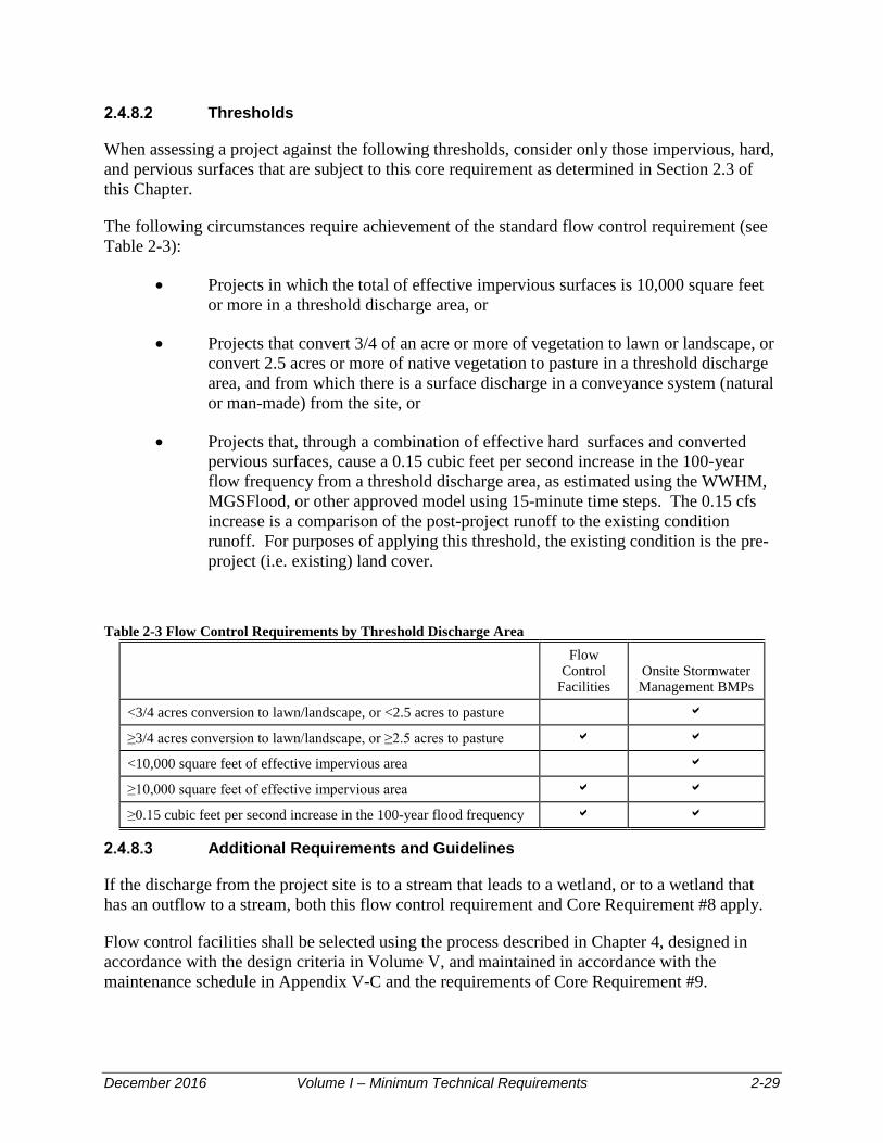
December 2016 Volume I – Minimum Technical Requirements 2-29
Thresholds
When assessing a project against the following thresholds, consider only those impervious, hard, and pervious surfaces that are subject to this core requirement as determined in Section 2.3 of this Chapter.
The following circumstances require achievement of the standard flow control requirement (see Table 2-3):
• Projects in which the total of effective impervious surfaces is 10,000 square feet or more in a threshold discharge area, or
• Projects that convert 3/4 of an acre or more of vegetation to lawn or landscape, or convert 2.5 acres or more of native vegetation to pasture in a threshold discharge area, and from which there is a surface discharge in a conveyance system (natural or man-made) from the site, or
• Projects that, through a combination of effective hard surfaces and converted pervious surfaces, cause a 0.15 cubic feet per second increase in the 100-year flow frequency from a threshold discharge area, as estimated using the WWHM, MGSFlood, or other approved model using 15-minute time steps. The 0.15 cfs increase is a comparison of the post-project runoff to the existing condition runoff. For purposes of applying this threshold, the existing condition is the pre-project (i.e. existing) land cover.
Table 2-3 Flow Control Requirements by Threshold Discharge Area
Flow Control
Facilities Onsite Stormwater Management BMPs
<3/4 acres conversion to lawn/landscape, or <2.5 acres to pasture
≥3/4 acres conversion to lawn/landscape, or ≥2.5 acres to pasture
<10,000 square feet of effective impervious area
≥10,000 square feet of effective impervious area
≥0.15 cubic feet per second increase in the 100-year flood frequency
Additional Requirements and Guidelines
If the discharge from the project site is to a stream that leads to a wetland, or to a wetland that has an outflow to a stream, both this flow control requirement and Core Requirement #8 apply.
Flow control facilities shall be selected using the process described in Chapter 4, designed in accordance with the design criteria in Volume V, and maintained in accordance with the maintenance schedule in Appendix V-C and the requirements of Core Requirement #9.

December 2016 Volume I – Minimum Technical Requirements 2-30
Application of sufficient types of On-site Stormwater Management BMPs can result in reducing the effective impervious area and the converted vegetation areas such that a flow control facility is not required. Application of “Full Dispersion” (BMP LID.11) also results in eliminating the flow control facility requirement for those areas that are “fully dispersed.”
2.4.9 Core Requirement #8: Wetlands Protection
Discharges to wetlands (directly or indirectly through conveyance systems) shall maintain the hydrologic conditions, hydrophytic vegetation, and substrate characteristics necessary to support existing and designated uses.
Applicability
This core requirement applies to all non-exempt projects that meet the thresholds of section 2.3 of this Chapter and where stormwater discharges into a wetland, either directly or indirectly, through a conveyance system.
Thresholds
The thresholds identified in Core Requirement #6: Runoff Treatment and Core Requirement #7: Flow Control shall also apply to determine the applicability of this requirement to discharges to wetlands.
Standard Requirement
Projects shall comply with Guide Sheets 1 through 3 in Appendix I-D of Ecology’s 2012 Stormwater Management Manual for Western (SWMMWW). The hydrologic analysis shall use the existing land cover condition to determine the existing hydrologic conditions, unless directed otherwise by the County or other regulatory agency.
Additional Requirements
Stormwater treatment and flow control facilities shall not be built within a natural vegetated wetland buffer, except for:
• Necessary conveyance systems as approved by the County; or,
• As allowed in wetlands approved for hydrologic modification and/or treatment inaccordance with Guide Sheet 2 in Appendix I-D of the 2012 EcologySWMMWW.
Objective
To ensure that wetlands receive the same level of protection as any other waters of the state. Wetlands are extremely important natural resources which provide multiple stormwater benefits, including ground water recharge, flood control, and stream channel erosion protection. They are easily impacted by development unless careful planning and management are conducted. Wetlands can be severely degraded by stormwater discharges from urban development due to

December 2016 Volume I – Minimum Technical Requirements 2-31
pollutants in the runoff and also due to disruption of natural hydrologic functioning of the wetland system. Changes in water levels and the frequency and duration of inundations are of particular concern.
Supplemental Guidelines
A wetland can be considered for hydrologic modification or stormwater treatment only in accordance with Thurston County Critical Areas Ordinance TCC Titles 17 or 24.
Appendix I-D of Ecology’s 2012 Stormwater Management Manual for Western Washington, Guidelines for Wetlands when Managing Stormwater, shall be used for discharges to natural wetlands and wetlands constructed as mitigation. While it is always necessary to pre-treat stormwater prior to discharge to a wetland, there are limited circumstances where wetlands may be used for additional treatment and detention of stormwater. These situations are considered in Guide Sheet 2 of Appendix I-D of Ecology’s 2012 SWMMWW.
Note that if selected runoff bypass is an alternative being considered to maintain the hydroperiod of a wetland, the hydrologic analysis must consider the impacts of the bypassed flow. For instances, if the bypassed flow is eventually directed to a stream, the flow duration standard, Core Requirement #7, applies to the bypass.
2.4.10 Core Requirement #9: Operation and Maintenance
A Maintenance Plan that is consistent with the provisions in this Manual shall be provided for all proposed stormwater facilities and BMPs, and the party (or parties) responsible for maintenance and operation shall be identified.
For private facilities, a project-specific agreement to maintain stormwater facilities and implement a pollution source control plan consistent with the provisions in Appendix I-E, for a single family residence, residential subdivision or commercial/industrial project, shall be executed by the party (or parties) responsible for maintenance of stormwater facilities and BMPs. The agreement shall normally be signed by the property owner and recorded with the Thurston County Auditor’s Office prior to final project acceptance by Thurston County. A draft copy of the agreement shall be included with the submittal of the Maintenance Plan for County review and acceptance. The maintenance agreement shall run with the land and be transferred automatically to all subsequent owners. Publicly owned facilities, such as those owned by Thurston County Public Works, Central Services, and Resource Stewardship departments, are not required to execute an agreement.
Property Owners’ Association Required
If the project is a subdivision, the Proponent shall form a Property Owners’ Association. The document creating the Property Owners’ Association shall, at a minimum, make provision for the following:
• Members of the Property Owners’ Association shall be responsible for maintenance of storm drainage facilities as described in the Maintenance Plan
December 2016 Volume I – Minimum Technical Requirements 2-32
• Inclusion by reference of the Maintenance Plan prepared by the Project Engineer in accordance with Chapter 3 of this volume
• Power to assess fees to maintain storm drainage facilities
• Sanctions in the event that Thurston County has to take action to maintain facilities. The following or substantially similar words shall appear in the document creating the Property Owner’s Association:
In the event Project Proponent (or successors or the Property Owners’ Association), in the judgment of Thurston County, fails to maintain drainage facilities within the plat, or if the Proponent or successors willfully or accidentally reduces the capacity of the drainage system or renders any part of the drainage system unusable, the Proponent or successors agree to the following remedy: After 30 days’ notice by registered mail to the Proponent or successors, Thurston County may correct the problem or maintain facilities as necessary to restore the full design capacity of the drainage system. Thurston County will bill the Proponent or successors for all costs associated with the engineering and construction of the remedial work. Thurston County may charge interest as allowed by law from the date of completion of construction. Thurston County will place a lien on the property and/or on lots in the Property Owners’ Association for payments in arrears. Costs or fees incurred by Thurston County, should legal action be required to collect such payments, shall be borne by the Proponent or successors.
• A Maintenance Covenant stating the Property Owners’ Association’s specific maintenance responsibilities shall be recorded on the plat and recorded against each lot in the subdivision. The covenant shall include the following or substantially similar language:
MAINTENANCE COVENANT
Easements are hereby granted for the installation, inspection, and maintenance of utilities and drainage facilities as delineated on the plat for subdivision______________ including unrestricted access for Thurston County staff to any and all stormwater system features for the purpose of routine inspections and/or performing maintenance, repair and/or retrofit as may become necessary. No encroachment will be placed within the easements shown on the plat which may damage or interfere with the installation, inspection, and maintenance of utilities. Maintenance and expense thereof of the utilities and drainage facilities shall be the responsibility of the Property Owners’ Association as established by covenant recorded under Auditor’s file number _____________.
Additional Requirements Inadequate maintenance is a common cause of failure for stormwater control facilities. Volume V, Appendix C, provides detailed maintenance guidelines and standards for each BMP presented in this Manual. The applicable checklists from Volume V shall be included in the Maintenance Plan for the project.

December 2016 Volume I – Minimum Technical Requirements 2-33
At private facilities, a copy of the Maintenance Plan shall be retained on-site or be reasonably accessible from the site, and shall be transferred with the property to the new owner. For public facilities, a copy of the Maintenance Plan shall be retained in the appropriate department. A log of maintenance activity shall be kept and be available for inspection by the County. An annual report on maintenance activities during the previous year is required to be submitted annually no later than August 31st Chapter 3 describes Maintenance Plan submittal requirements, which are included as part of the Drainage and Erosion Control Plan for the project.
2.4.11 Core Requirement #10: Financial Liability
To ensure compliance with these standards, performance bonding or other appropriate financial instruments shall be required for all projects.
Financial Guarantees
In accordance with Thurston County Code Title 15.05.040, the project proponent/owner shall provide financial guarantees to insure that:
• The project will operate according to the design approved by the project engineer, and
• Operation of erosion control facilities will provide protection against siltation of surface water, erosion, and damage to adjacent properties.
The project proponent/owner shall provide a financial guarantee to the Administrator to ensure satisfactory maintenance of drainage facilities for a minimum of 2 years from final plat acceptance or acceptance of the project, whichever is later, in accordance with the Maintenance Plan submitted as part of the Drainage and Erosion Control Plan. The financial guarantee shall continue in effect until the drainage facilities are fully established, functioning per design and determined not to have substantial maintenance problems. Upon acceptance of the project by Thurston County and after minimum time requirements and other conditions have been met the project proponent shall request in writing that the financial guarantee be released. Said request shall document that the requirements for financial guarantee release have been met.
If the stormwater system is dependent on a property owners’ association (POA) for maintenance, then the applicant shall present evidence of a POA being established and active before the financial guarantee is released. The holder of the financial guarantee shall establish a mechanism prior to sale of all or part of the project that ensures that the financial agreement holder has the legal right and ability to perform required stormwater system maintenance while the financial guarantee is in effect. Proof of same shall be provided to the Administrator prior to acceptance of the financial guarantee.
The mechanism may include a replacement of the financial guarantee by an identical guarantee from a third party (such as a POA) who takes responsibility for stormwater system maintenance. The original financial guarantee shall not be released until the replacement guarantee is accepted by the Administrator and legally recorded.

December 2016 Volume I – Minimum Technical Requirements 2-34
The amount of the guarantee shall be 25 percent of the construction cost of the drainage facilities. The applicant shall submit an itemized work sheet for the cost of facilities, acceptable to the Administrator before the financial guarantee amount is fixed. The bond quantities worksheet provided in Appendix I-D shall be used to prepare the cost estimate.
With County acceptance, and to the extent allowed by law, all project guarantees may be replaced by a single guarantee, provided that the total amount guaranteed shall at no time be less than the sum of the separate guarantees replaced. Furthermore, such guarantees shall clearly delineate those separate guarantees which they are intended to replace.
Subject to County acceptance, financial guarantees may be any of the following:
• Cash deposit escrow account
• Assignment of interest in a bank account
• Irrevocable letter of credit from a financial institution
• A bond.
All financial guarantees shall run continuously until released by the County.
2.4.12 Core Requirement #11: Offsite Analysis and Mitigation
An analysis consistent with the following guidelines shall be submitted with appropriate plan per Volume I, Chapter 3.
Applicability
Core Requirement #11 applies to those projects meeting the thresholds outlined in Chapter 2. The Project Engineer or applicant (for abbreviated plans) shall submit an off-site analysis that assesses the potential off-site impacts of the project’s stormwater discharges.
When downstream drainage courses are inadequate, systems are undersized, or when (in the opinion of the Administrator or designee) property may be adversely affected by existing or proposed stormwater release rates, additional stormwater flow control measures may be required. Such determination by the Administrator or designee may be based upon information submitted by the applicant, existing information indicating problem areas, information received from or statements from property owners or residents near the project site, or current or past drainage problem litigation near the project. Additional information, calculations, or studies may be required of the applicant to assist the Administrator in making this determination.
Requirements
All projects shall perform a qualitative analysis downstream from the site to the receiving water or up to one mile, whichever is less, even if 100 percent infiltration is proposed. If the receiving water is within one-quarter mile, the analysis shall extend within the receiving water to one-quarter mile from the project site. The analysis shall extend one-quarter mile beyond any

December 2016 Volume I – Minimum Technical Requirements 2-35
improvements proposed as mitigation. The analysis must extend upstream to a point where any backwater effects created by the project cease. The analysis shall meet the requirements in Chapter 3.
A quantitative analysis may be required for any project deemed to need additional downstream information or where the Project Engineer or the Administrator or designee determine that a quantitative analysis is necessary to evaluate the off-site impacts or the capacity of the conveyance system.
This quantitative analysis shall determine conveyance system performance for the appropriate design events (see Volume III), both with and without the proposed development and based on full development of the contributing basin based on land use zoning. The Administrator or designee shall have the discretion to specify the distance and level of detail to be provided by the Project Engineer. The Administrator or designee shall consider factors such as the relative size of the new development, availability of other hydrologic work for the drainage area, and results of the qualitative analysis in making this determination.
If downstream conveyance system capacity is determined to be inadequate or undersized based on an evaluation of the entire contributing area at full build-out based on the current zoning, the applicant has the following options:
• Provide additional flow control, LID, or infiltration measures as required by the County to reduce stormwater discharge rates and/or volumes to pre-development conditions, or
• Correct or improve downstream drainage conditions so that the capacity is adequate to convey drainage from all contributing properties, or
• At such time as the County establishes a program for payment in lieu of improvements, the applicant may contribute to a dedicated fund to provide the downstream improvements required per the provisions of the program.
Any off-site improvements proposed by the applicant will require the applicant to obtain easements from the owners of any property where work occurs.
The Administrator or designee may impose stricter discharge, infiltration or detention standards, or require off-site mitigation work to an existing conveyance system if the discharge from the Project is reasonably expected to result in any of the following:
• Flooding
• Loss of aquatic habitat due to either high or low flows
• Property damage
• Water quality problems such as violations of surface water quality standards as identified in a Basin Plan or TMDL (Water Clean-up Plan); or violations of ground water standards in a wellhead protection area.

December 2016 Volume I – Minimum Technical Requirements 2-36
• Erosion (upland erosion impacts, including landslide hazards, or stream channel erosion at the outfall location).
• An unacceptable interruption of vital services
• Exceeding the capacity of a downstream conveyance system based on full basin development.
If the Project Engineer (or Administrator or designee) determines that greater treatment, infiltration or storage volumes, lower release rates, or downstream improvements are needed, he or she shall specify project design criteria or other means to relieve the downstream problems, providing that such a solution will not violate minimum standards established in this DDECM. The Administrator or designee shall have the final decision as to the scope and depth of the analysis.
Other means might include increases in downstream flow capacity or off-site detention and infiltration facilities. Plans and financing for these alternatives will be subject to the acceptance of the Administrator or designee.
The Offsite Analysis shall also include how the runoff from any public roadway frontage abutting the property is managed (qualitative at minimum, quantitative if meets above conditions). The project shall incorporate any runoff from public roadway frontage into the drainage system for the project.
Objective
To identify and evaluate off-site water quality, erosion, slope stability, and drainage impacts that may be caused or aggravated by a proposed project, and to determine measures for preventing impacts and for not aggravating existing impacts. Aggravated shall mean increasing the frequency of occurrence and/or severity of a problem.
2.5 Deeds and Easements
The following deeds and easements shall be used to convey property or rights to Thurston County:
• Statutory warranty deed (individual, partnership, or corporate): conveys real property to Thurston County
• Storm sewer easement: conveys to Thurston County the right to have and maintain a storm sewer system across a specific parcel of property
• Stormwater Maintenance Agreement: delineates responsibilities of party responsible for stormwater system maintenance and grants to Thurston County the right to have access to stormwater facilities for purposes of inspection, maintenance, or repair if the party responsible for maintenance fails to take required actions in accordance with the maintenance agreement.

December 2016 Volume I – Minimum Technical Requirements 2-37
• Slope and utility easement: conveys the right to have fill material or a cut slopeand utilities on private property
• Quitclaim deed: conveys maintained but undocumented right-of-way to ThurstonCounty
• Drainage Easement: conveys to Thurston County the right to access, use, andmaintain a specific area of a parcel of property for purposes of storm drainage.This may include stormwater facilities for water quality treatment or flow control,dispersion, conveyance, or other purposes.
Prior to final project acceptance by Thurston County, all easements, dedicated tracts, buffers, or similar features associated with the stormwater facilities of a development, including a subdivision, shall be shown on the face of the plat or project site plan. In addition, written legal documents shall be prepared and recorded against all parcels to which the easement or dedication applies. Easements or tracts providing access to stormwater facilities shall be delineated in the field with permanent markers to prevent encroachment. See Section 3.9.6.2 for signage requirements.
2.6 Acceptance of New Stormwater Facilities
The developer of a stormwater facility is responsible for construction and maintenance of the facility, which must be in compliance with this Manual.
2.6.1 Public Ownership
The County does not accept maintenance responsibility for private stormwater facilities constructed by private developers.
2.6.2 Private Ownership – Subdivision Projects
If the project is a subdivision or short subdivision, the project proponent/owner shall form a property owners’ association (POA). The document creating the association shall provide for the following, at a minimum:
• The POA shall be responsible for maintenance of storm drainage facilities
• Inclusion by reference of the Maintenance Plan prepared by the project engineerin accordance with this Manual
• Power to assess fees to maintain storm drainage facilities
• Responsibility for payment of financial sanctions/repayments should the Countyhave to conduct repairs due to hazardous conditions.
The maintenance covenant and statement of sanctions described under Core Requirement #9, Section 2.4.11 will be included in the document establishing the POA and shall be recorded with

December 2016 Volume I – Minimum Technical Requirements 2-38
the Thurston County Auditor for the plat and recorded against each lot within the subdivision or short division.
2.6.3 Private Ownership – Other Projects
If the project is other than a subdivision, short subdivision, or large lot division, the applicant will describe the organization or persons that will own and maintain the facility and provide evidence that maintenance activities will be performed and are adequately financed.
2.7 Adjustments
Adjustments to the Core Requirement may be granted prior to permit acceptance and construction. The Administrator may grant an adjustment subject to a written finding of fact that documents the following:
• The adjustment provides substantially equivalent environmental protection
• Meeting the objectives of safety, function, environmental protection and facility maintenance, based upon sound engineering.
2.8 Exceptions/Variances
The Administrator may grant exceptions to the Core Requirement or variances from the design standards, submittal requirements, or any other standards provided in the Manual provided that the applicant demonstrates their projects will substantially meet flow control and water quality performance goals established by or implicit in these standards per the guidelines below.
2.8.1 Exceptions/Variances to Core Requirements
Exceptions to the Core Requirement shall only be granted after legal public notice of an application for an exception; legal public notice of the Administrator’s decision on the application and a written finding of fact that documents the Administrator’s decision to grant an exception to the Core Requirement.
The Administrator may grant an exception to the Core Requirement if such application imposes a severe and unexpected economic hardship. To determine whether the application imposes a severe and unexpected economic hardship on the project applicant, the Administrator must consider and document – with written findings of fact – the following:
• The current (pre-project) use of the site, and
• How the application of the Core Requirement(s) restricts the proposed use of the site compared to the restrictions that existed prior to the adoption of the Core Requirement; and
• The possible remaining uses of the site if the exception were not granted; and

December 2016 Volume I – Minimum Technical Requirements 2-39
• The uses of the site that would have been allowed prior to the adoption of theCore Requirement; and
• A comparison of the estimated amount and percentage of value loss as a result ofthe Core Requirement versus the estimated amount and percentage of value lossas a result of requirements that existed prior to adoption of the Core Requirement;and
• The feasibility for the owner to alter the project to apply the Core Requirement.
2.8.2 Variances/Exceptions from Design Standards, Submittal Requirements, etc.
The Administrator may grant a variance to design standards, submittal requirements, or any other standards provided in the Manual, not including exceptions to the Core Requirement (addressed above) subject to a written finding of fact that documents the following:
• There are special physical circumstances or conditions peculiar to the land, suchas size, shape, topography, or location, such that the strict application of theseprovisions would deprive the property owner of rights commonly enjoyed byother properties similarly situated; OR
• The site is being redeveloped and certain site investigations or installedstormwater facilities would require that existing structures be removed ordamaged; OR
• The site is being redeveloped and the changes are either very small or configuredin such a way that in the Administrator’s or designee’s opinion some requirementsof the Manual cannot practically be met; OR
• The project is to be completed within an existing right-of-way which is ofinadequate size to install required facilities and which cannot be expanded due toencroaching structures or setbacks;
Additional Criteria:
In addition, any exception/variance must meet the following criteria:
• That the granting of the exception/variance will not increase risk to the publichealth and welfare, nor be injurious to other properties in the vicinity and/ordownstream, and to the quality of waters of the state; AND
• The exception is the least possible exception that could be granted to comply withthe intent of the Manual; AND
• A fee-in-lieu, based on the avoided cost or value of the exception or variance,may be collected by the County subject to specific requirements regarding fee-in-lieu set by Thurston County at such time as a fee-in-lieu program is established.

December 2016 Volume I – Minimum Technical Requirements 2-40
2.8.3 Supplemental Guidelines
The adjustment, exception and variance provisions are important elements of the plan review and enforcement programs. They are intended to maintain a necessary flexible working relationship between the applicant and the County. The Administrator will consider these requests judiciously, keeping in mind both the need of the applicant to maximize cost-effectiveness and the need to protect off-site properties and resources from damage.
2.9 Interpretations and Appeals
Any person who disagrees with any decision of the Administrator or Thurston County regarding application of this Manual may request an interpretation. The request for an interpretation shall be submitted in writing to the Administrator or designee as defined herein. The Administrator or designee shall respond to that person in 30 days.
Appeals from an Administrative decision may be taken to the Hearings Examiner by any aggrieved person or by an officer, department, board, or commission of the jurisdiction affected by any order, requirement, permit, decision, or determination made by the Administrator or designee in the administration or enforcement of this Manual or any subsequent amendment thereto. The appeals procedure shall be identical to the appeal procedures of the Thurston County zoning code which requires the appeal to be in writing and made within 14 days of the administrative decision being appealed. A fee is required to be paid for an appeal.
2.10 Severability
If any provisions of this Manual or their application to any person or property are amended or held to be invalid, the remainder of the provisions in this Manual in their application to other persons or circumstances shall not be affected.

December 2016 Volume I – Minimum Technical Requirements 3-1
Stormwater Submittal Requirements 3.1 Introduction
Completion of submittals described in this chapter documents compliance with Core Requirement# 1 (Stormwater Site Planning) and Core Requirement #2 (Construction SWPPP), as described in Chapter 2. The following submittals, and their applicability to different types and sizes of projects, are described in this Chapter:
• Abbreviated Drainage Plan
• Engineered Abbreviated Drainage Plan
• Short Form Construction Stormwater Pollution Prevention Plan
• Drainage and Erosion Control Plan --includes a Drainage and Erosion ControlReport, Permanent Stormwater Control Plan (drawings and specifications) and aMaintenance Plan.
• Construction Stormwater Pollution Prevention Plan (includes temporary erosionand sediment control drawings and a narrative).
All non-exempt projects are required to prepare one or more of the above submittals for County review and acceptance.
The County may require a project to prepare a “scoping report” and the applicant or County may request a “scoping meeting” early in the project to discuss the development site’s conceptual stormwater approach. This process may also be used to identify potential problems and to outline submittal requirements, scope, and content.
This chapter describes the submittal process for drainage review of projects submitted to Thurston County for permits. However, the site characterization and stormwater planning process should begin before submittal preparation.
3.1.1 Site Characterization
Site planning and design are integrated with stormwater management requirements. The manner in which a site is developed will impact the extent and cost of stormwater treatment and flow control. This section provides techniques that should be implemented to reduce both the impacts of projects on receiving waters and the overall cost of the stormwater management system.
Low impact development site design is intended to complement the predevelopment conditions on the site. However, not all sites are appropriate for a complete LID project, as site conditions determine the feasibility of using LID techniques. The development context shall be established by an initial site analysis consistent with the requirements of this section.

December 2016 Volume I – Minimum Technical Requirements 3-2
The initial inventory and analysis process will provide baseline information necessary to design strategies that utilize areas most appropriate to evaporate, transpire, and infiltrate stormwater, and achieve the goal of minimizing the pre- development natural hydrologic conditions on the site.
Take an inventory of the site prior to design activities and identify the following:
Soils Analysis
Use of many of the BMPs described in this Manual requires a detailed understanding of site soils. A preliminary soils analysis of the overall site to identify the locations of different soil types, the layering of soils, existence of hardpan, etc. should be conducted prior to major site planning. The objective of site planning should be to locate new impervious surfaces over soils that are less permeable and locate proposed stormwater facilities over soils that are more permeable to promote infiltration.
A preliminary assessment of infiltration rates of soils throughout the site should be considered early in the process for establishing potential BMP locations. More detailed infiltration evaluation as described in Volume III can occur once preliminary locations of infiltration facilities are established. Establishing an estimated overall site infiltration rate will also determine whether the minimum infiltration volume requirement of Core Requirement #7 will apply to the project.
A few strategically located test pits or borings are generally adequate for this preliminary soils assessment.
Critical Areas (e.g., wetlands, streams, or stream buffers)
Sites that have streams, wetlands, high groundwater, steep slopes, geologic hazard areas, well head protection areas or a number of other features are considered critical areas as defined by Thurston County Code Title 17 and Title 24. Many have been assigned buffer zones that restrict activities that can occur within them. These critical areas and associated buffers must be indicated on site plans and methods to protect them must be instituted from the start of development.
Natural Drainage Systems and Outfalls
Core Requirement #4 stipulates that natural drainage patterns shall be maintained, and discharges from the project site shall occur at the natural location, to the maximum extent practicable (see Chapter 2). By identifying natural drainage patterns at the start of the project, the designer can ensure that drainage routes are protected and that (where possible) the site is designed to minimize the conveyance facilities required to transport stormwater to natural drainage locations. Preserving natural drainage also decreases the likelihood of flooding or other problems downstream.

December 2016 Volume I – Minimum Technical Requirements 3-3
Significant Trees and Native Vegetation
By designing the site to protect significant trees and native vegetation, the designer will have more opportunities to use LID BMPs such as infiltration and dispersion for stormwater management. Native vegetation areas suitable for dispersion and where trees can be retained without risk of toppling should be mapped and included in the site plan.
Steep Slopes
Unless preventive measures are taken, stormwater runoff from development will cause additional erosion problems or even landslides on steep slopes. Many stormwater BMPs do not work well in areas with steep slopes, and their use is limited in those locations. Identify through topographic mapping and site visits the location of slopes greater than 10 to 15 percent and show these on the site maps. Special studies may be required for facilities located within setback distances to steep slopes. Marine bluffs are a special case of steep slopes for properties located along the marine waterfront. Thurston County Code, Title 17, includes specific requirements related to properties along marine bluffs.
Existing Topography
How does the undeveloped site deal with stormwater? If most stormwater currently infiltrates rather than running off the site, the finished site should use infiltration as the main method of stormwater management. This lessens the need for constructing new drainage channels or installing pipe, lessens the likelihood of downstream flooding, and protects downstream water quality.
If the topography provides large areas of surface storage through many small dips and hollows, consider providing on-site storage. If the existing topography already drains to a natural channel, designing the drainage system to follow this means less grading and less likelihood of erosion, if existing channel vegetation is preserved.
Design practices that consider and adapt to a site’s characteristics, like the features listed above, are sometimes referred to as Low Impact Development. LID techniques are intended to more closely mimic predevelopment watershed hydrologic functions than traditional development practices.
LID techniques are emphasized throughout this Manual. These techniques include reducing impervious surfaces (described in BMP LID.03), preserving native vegetation (BMP LID.01), and protecting soils (BMP LID.02). They require advance planning, but will likely reduce costs associated with grading, stormwater treatment, flow control, stormwater conveyance, paving materials, curbs, and landscaping (if native vegetation is preserved). The County’s NPDES Phase II permit also requires LID measures be given preferential consideration.
Preliminary sources of topographic information such as USGS maps and the Thurston County Geodata system can be used for preliminary evaluation of a site; however, topographic surveying by licensed surveyors and site visits to verify conditions by the project engineer or designer should be conducted to support design and before construction.

December 2016 Volume I – Minimum Technical Requirements 3-4
3.1.2 Site Design – Smart Design and Low Impact Development
Knowing how the site processed stormwater historically is important in determining appropriate better site design strategies. The site analysis (see Section 3.1.1) will provide information on how the site and the surrounding areas process stormwater both currently and historically (before any land use changes had altered those processes). This information will aid the designer in determining preferred site layout options, and in deciding what appropriate site design BMPs will help either maintain or restore natural pre-developed stormwater processes.
As presented in Chapter 1, and as required by Core Requirement #5, to effectively protect critical areas and receiving waters while taking advantage of a site’s overland and subsurface flow, infiltration, storage, and evapotranspiration characteristics, the applicant shall consider first the following Low Impact Development strategies:
• Minimize effective impervious area (EIA): By avoiding the use of curbs (wherepermitted), designing reverse slope sidewalks, and allowing impervious surfacesto drain overland to pervious areas, a site can be designed to avoid concentratingrunoff allowing for a higher time of concentration and greater infiltration.Ecology allows a flow credit for reverse slope sidewalks that drain onto nativesoils (see BMP LID.03). When impervious surfaces drain onto lawn or gravelprior to being collected in the site stormwater system, peak flows and volumes ofstormwater from the site are reduced, thereby reducing stormwater managementcosts.
• Onsite stormwater management: Many parts of Thurston County have soils withhigh infiltration rates. By designing your site so that small areas drain tolocalized facilities, such as bioretention facilities (BMP LID.08), you may be ableto manage your runoff entirely on-site, using areas not much larger than thoseneeded for traditional landscaping. This practice also assures compliance withCore Requirement #5.
• Alternative paving surfaces: For areas of private developments with low trafficvolume and where allowed by Thurston County road standards for private roads,alternative paving surfaces (BMP LID.09) such as porous concrete or asphalt,permeable interlocking concrete pavers, or grid systems can be highly effective atreducing or eliminating stormwater runoff and associated stormwater treatment,flow control, and conveyance costs. Even with very low infiltration rates ofunderlying soils, alternative paving surfaces are highly effective at controllingstormwater runoff. Alternative paving surfaces are not allowed within the publicright-of-way or for private roadways which may be dedicated to the County.
3.2 Submittal Review and Acceptance Process
This is a conceptual overview of a typical submittal review and acceptance process, shown in Figure 3-1. For the latest information on submittal requirements and the acceptance process, contact the Permit Assistance Center or see Thurston County’s permit website at: <http://www.co.thurston.wa.us/permitting/>.

December 2016 Volume I – Minimum Technical Requirements 3-5
Figure 3-1 Submittal Review and Approval Process.

December 2016 Volume I – Minimum Technical Requirements 3-6
3.2.1 Presubmittal Meeting
A presubmittal meeting is an informal meeting between a project applicant and County and local government staff who will review the proposal. The applicant may have advisors present (e.g., realtor, surveyor, and engineer). Since this is an informal meeting and no decisions will be made, public comment is limited to the applicant and their advisors.
The project applicant must provide contact information, possible development options, and a map showing the property boundaries, topography, and zoning.
Sometimes, a presubmittal meeting is a required first step in a land use or subdivision process. The meeting is also a good way to obtain important information before beginning your project. For more information about the presubmittal meeting, see Thurston County’s permit website at: <http://www.co.thurston.wa.us/permitting/>.
Drainage Scoping Report/Meeting
For any project exceeding the thresholds of Chapter 2 for which Core Requirements #6 (Runoff Treatment), and/or 7 (Flow Control) apply, a Drainage Scoping Report shall be submitted prior to project application submittal. Based on the review of the Drainage Scoping Report, or at the request of the applicant, a drainage scoping meeting may be scheduled to assist the applicant in complying with stormwater requirements.
The Drainage Scoping Report shall include the following:
• A letter of transmittal requesting a Drainage Scoping Report review and includingapplicant, property owner, and parcel information required to identify the propertyand its location
• A written description of the project including overall stormwater managementstrategy proposed for the site including a strategy for meeting Core Requirement#5, i.e., will the project use the BMP menu approach, the LID Flow DurationStandard, or LID is infeasible on the site
• Maps of the site’s existing conditions showing ground cover, existing drainage,topography, soils, and adjacent areas
• A general vicinity map showing surrounding properties including topography,downstream, and upstream areas of the project
• Results of preliminary geotechnical investigations, test pits, etc. as well as NaturalResources Conservation Service (NRCS) soils mapping information
• A completed conceptual site plan, including a scale drawing with topography ofthe site and showing conceptual lot and building locations, impervious area totals,proposed drainage facilities, zoning information including any limits onimpervious surfaces, tree retention requirements, landscape buffers, etc.

December 2016 Volume I – Minimum Technical Requirements 3-7
• If the project is a redevelopment project, a preliminary estimate of projectconstruction costs should be submitted.
• The applicant shall also submit a completed source control checklist (seeVolume IV, Source Control).
Upon review of the Drainage Scoping Report, Thurston County will prepare a response letter accepting the report and providing any additional information, studies, recommendations, suggestions, or additional requirements that might apply to the project that should be included in the submittal documents. If the County determines that a drainage scoping meeting is required, this will be included in the response letter.
3.2.2 Preliminary Report Submittal
Based on comments received from the Drainage Scoping Report review and drainage scoping meeting, the applicant then produces a preliminary Drainage and Erosion Control Plan including a preliminary drainage report, Permanent Stormwater Control Plan, and a revised source control checklist for inclusion in the permit or land use application package.
3.2.3 Final Report Submittal
After receiving preliminary acceptance of the project (Preliminary Plat Approval, Site Plan Review Approval, etc.) the applicant shall submit a final Drainage and Erosion Control Plan including a complete, Drainage Report, Maintenance Plan, Construction SWPPP, and final Permanent Stormwater Control Plan (construction drawings) for the project for County review.
Drainage and Erosion Control Plans submitted to the County will be routed to the Administrator or designee for review concurrently with other project plans (e.g., vegetation removal and clearing, final grading, landscaping, water and sewer, community on-site sanitary waste disposal system, roads, utilities plans). Incomplete Drainage and Erosion Control Plans will be returned to the applicant without being reviewed.
Until the Administrator or designee accepts the submittal and confirms that erosion control devices are in place as per the plan, the County will not:
• Grant any development, building, or other related permit except as needed toinstall erosion and sediment control facilities
• Allow project clearing, earthwork, demolition, site work, or construction to begin
• Allow construction of footings for structures.
3.2.4 Final Report Acceptance
After the applicant completes changes to the final report required by the County, the County shall issue a Final Report Acceptance, allowing construction to begin.

December 2016 Volume I – Minimum Technical Requirements 3-8
3.2.5 Final Project Acceptance
The following must be completed before the County will accept plats, grant certificates of occupancy, release financial securities related to drainage and erosion control, or accept final construction.
For those filing Drainage and Erosion Control Plans:
• Drainage and Erosion Control Plan accepted by the County
• Stormwater Facilities Maintenance Plan accepted by the County
• Construction Inspection Report and as-built drawings in electronic format (PDF and CAD)
• Special requirements on the cover sheet of a plat, such as BMP volumes or other design criteria, and a general easement for protection and maintenance
• Filing of covenants on lots, the POA articles of incorporation and CC&R’s, maintenance agreements, easements, agreements with adjacent property owners, conservation easements, and similar documents as required in the Drainage and Erosion Control Plan and Thurston County Code.
• Conditions of acceptance fulfilled
• Site permanently stabilized and restored, and temporary erosion control measures removed.
For Abbreviated Drainage Plan or Engineered Abbreviated Drainage Plan projects:
• All conditions of the Abbreviated or Engineered Abbreviated Drainage Plan must be met, except that replanting may be delayed with the concurrence of the County.
• An 8½ x 11” version of the Abbreviated or Engineered Abbreviated Drainage Plan showing the location of drainage structures, conveyances, drywells, and dispersion areas shall be created and recorded with the Thurston County Auditor for the subject property.
Abbreviated Drainage Plans must be submitted with the application for permit or preliminary project acceptance.
3.3 Submittal Format
Submittals shall be in accordance with submittal requirements of the Thurston County Code and Development Services appropriate for the project type. At least one copy of all submitted documents shall be in electronic (Adobe PDF) format. Where required, full size plans shall be 22” x 34” and all information and text shall be of sufficient size to be readable when reduced to
December 2016 Volume I – Minimum Technical Requirements 3-9
11” x 17” size. Where plot plans are required, such as for abbreviated plan submittals, they shall be 11” x 17”. Examples are available from the County.
3.4 Submittal Types
Submittals required for drainage review depend on the project’s type, size, location, and proposed treatment. Figure 3-2 summarizes required submittals, depending on whether the project is 1) eligible for an Abbreviated Drainage Plan; 2) located within or near a critical area; and 3) subject to Core Requirement #2, Construction Stormwater Pollution Prevention Plan (SWPPP). Consult relevant sections of this Manual to determine whether these categories apply to the proposed project.
In terms of submittals, there are four categories of Thurston County projects:
1. Projects exempt from submittal requirements
2. Projects eligible for an Abbreviated Drainage Plan
3. Projects requiring an Engineered Abbreviated Drainage Plan
4. Projects requiring a complete Drainage and Erosion Control Plan.
Projects that may submit an Abbreviated Drainage Plan or an Engineered Abbreviated Drainage Plan may have additional submittal requirements (e.g., a Short Form Construction SWPPP and Source Control Plan) if they are subject to Core Requirement #2 or #3. These submittals are briefly described below.

December 2016 Volume I – Minimum Technical Requirements 3-10
Figure 3-2 Flow Chart for Determining Submittal Requirements

December 2016 Volume I – Minimum Technical Requirements 3-11
Table 3.1 Thresholds for Abbreviated Plans, Stormwater Pollution Prevention Plans, and Drainage Control Plans

December 2016 Volume I – Minimum Technical Requirements 3-12
3.4.1 Projects Exempt from Submittal Requirements
In addition to those projects that are categorically exempt from the requirements of this Manual (see Section 2.2) the following projects are exempt from the submittal requirements but shall be designed and constructed consistent with the requirements of this Manual:
• Emergency projects which if not performed immediately would substantially endanger life or property are exempt from submittal requirements. Upon resolution of the emergency, the property owner must either restore the site to its original condition or comply with the requirements of this Manual. Contact Thurston County to determine which regulatory requirements must still be met after the emergency situation has been addressed.
• Public works road projects completely within the right-of-way which do not add impervious surface and for which previously dispersed flows are not concentrated (i.e., adding curb and gutter).
• Public works road widening projects including minor right-of-way acquisitions and for which no change in the type of conveyance system (i.e., from open channel to piped system) is proposed and for which previously dispersed flows are not concentrated (i.e., adding curb and gutter).
• Projects in rural areas (outside the NPDES boundary) which add or modify hard surfaces and the total of existing hard surfaces (including the modified hard surfaces) plus the new hard surfaces is less than 5% of the parcel, and grading is less than 5,000 cubic yards, and land disturbing activity is less than 10% of the parcel—providing that there is no increase in runoff or sediment discharge to adjoining property or to waters of the United States. If the property abuts a public roadway frontage, the area of the roadway frontage contributing drainage to the site shall be included in the impervious area computation and runoff from the roadway shall be accounted for.
3.4.2 Abbreviated Drainage Plan
Abbreviated Drainage Plans are streamlined submittals allowed for projects on land zoned residential, agriculture, or forestry, where none of the special conditions requiring an Engineered Abbreviated Plan apply and the project meets one or a combination of the following criteria:
• Project on a single lot where less than 2,000 square feet of new impervious surface is created and less than 7,000 square feet of land is disturbed.
• Project on a single lot where greater than 85 percent of the lot area can be classified as Type A/B (outwash) soils and where less than 5,000 square feet of new impervious surface is created, less than ¾ acre is converted to lawn/landscape, and less than 2.5 acres are converted to pasture.
December 2016 Volume I – Minimum Technical Requirements 3-13
• Project subject to a building permit on a single lot of any size, if the lot is within a development that has a previously accepted and currently functioning stormwater system that includes the future development of that lot.
• Project converting less than 3/4 of an acre from native vegetation to lawn or landscaped areas and creating less than 2000 square feet of new impervious surface or meeting one of the other conditions of this section related to limits on impervious surface.
• Project converting less than 2.5 acres from native vegetation to pasture or timberland to commercial agriculture and creating less than 2000 square feet of new impervious surface or meeting one of the other conditions of this section related to limits on impervious surface.
• Project on a parcel of greater than 1 acre outside the NPDES Phase II permit boundary where 85% of the parcel area can be classified as Type A/B (outwash) soils on which new, replaced, and existing hard surfaces including any public roadway frontages are less than 10 percent of the site, and total non-native pervious plus impervious surfaces are less than 35 percent of the site, and no substantial ( >0.15 cfs using a 15 minute time step) increase in runoff or sediment discharges to adjoining property or to waters of the United States occurs as a result of the project.
• Project on a parcel of greater than 2.5 acres outside the NPDES Phase II permit boundary with any soil type on which new, replaced, and existing hard surfaces are less than 10 percent of the site, and total non-native pervious plus hard surfaces are less than 35 percent of the site, and no substantial (>0.15 cfs using a 15 minute time step) increase in runoff or sediment discharges to adjoining property or to waters of the United States occurs as a result of the project
• Grading project requiring a permit, where total grading is less than 500 cubic yards with less than 2,000 square feet of hard surface added and less than 7,000 square feet of land disturbing activity occurs and no change to existing drainage occurs.
In computing the area thresholds above, if the project site abuts a public roadway and roadway frontage improvements are required, the hard surfaces and disturbed areas associated with the frontage improvements shall be included in the area calculations. In calculating existing hard surfaces the area to the centerline of the public road fronting the property shall be included.
Additional submittals (such as a Construction SWPPP or Source Control Plan) may be required to comply with Core Requirements #2 and #3 or for projects with critical areas as described below.

December 2016 Volume I – Minimum Technical Requirements 3-14
3.4.3 Engineered Abbreviated Drainage Plan
An Engineered Abbreviated Drainage Plan is a streamlined submittal similar to an Abbreviated Drainage Plan that must be prepared by a civil engineer licensed in the State of Washington and includes additional design, calculations and specifications beyond those required by an Abbreviated Drainage Plan (see Section 3.7). An Engineered Abbreviated Drainage Plan is allowed for the following project types:
• Project that meets the general requirements for an Abbreviated Drainage Plan, but
has any of the following special conditions:
Any critical areas as defined by Thurston County Code, Title 17 (e.g., wetlands, aquifer recharge areas, geologic hazard areas, high groundwater areas, special management areas, flood hazard areas, shoreline protection areas, lakes, streams, etc.) exist within 200 feet of the boundaries of the disturbed area of the project site
Any project located within 200 feet of a Marine Bluff Hazard Area as defined by Thurston County Code, Title 17. (Note: Any project located within the Marine Bluff Hazard Area shall prepare a full Drainage and Erosion Control Report in accordance with Title 17, TCC)
For lots less than 1 acre in size with soils not classified as predominately Type A/B (outwash) soils, or where the average slope across the parcel is greater than 10 percent or any slope 15 percent or greater with 10 foot or greater height exists
Project is located in an area that has historically had drainage problems including flooding and/or water quality problems
Proposed or existing land use is commercial, industrial, or multi-family residential
Subdivision (more than a single lot being developed)
• Other Single Family Residential or Duplex projects on a single lot not meeting criteria for an Abbreviated Drainage Plan and not located within a Marine Bluff Hazard Area
• Grading projects requiring a permit, where total grading is less than 5,000 cubic yards with less than 5,000 square feet of impervious surface added and less than ¾ of an acre of native vegetation converted to lawn or landscape and no change to existing drainage occurs.
Engineered Abbreviated Drainage Plans shall be stamped by and prepared by, or under the direct supervision of, a civil engineer licensed in the State of Washington. All Core Requirement

December 2016 Volume I – Minimum Technical Requirements 3-15
applicable to the project as described in Chapter 2 shall be addressed by the Engineered Abbreviated Drainage Plan.
3.4.4 Drainage and Erosion Control Plan
Applicants with projects not eligible for an Abbreviated Drainage Plan or Engineered Abbreviated Drainage Plan shall submit a Drainage and Erosion Control Plan. All such plans shall be stamped by and prepared by, or under the direct supervision of, a civil engineer licensed to practice in the State of Washington (hereinafter referred to as the “Project Engineer”).
3.5 Abbreviated Drainage Plan
This section summarizes the Core Requirement of an Abbreviated Drainage Plan. The Administrator or designee may increase plan submission and runoff control requirements for projects expected to have a significant impact on sensitive natural resources, or projects that could exacerbate existing flooding or water quality problems.
An Abbreviated Drainage Plan consists of a written project summary, a plot plan, and any other requirements set by the Administrator or designee. Abbreviated Drainage Plans need not be stamped with the seal of a licensed Professional Engineer.
For projects which are required to address more than Core Requirement #2 (Construction SWPPP), the Abbreviated Drainage Plan shall address all Core Requirement applicable to the project.
3.5.1 Plot Plan
The plot plan submitted for the Abbreviated Drainage Plan shall be sufficiently clear to see the footprint of structures and other features described below. Drawings shall be 11” by 17” in size. Lines shall be drawn with a straight edge and features shall be to scale.
The plot plan shall contain the following information:
• Name, address, and telephone of the applicant, project proponent and property owner (may be the same person)
• Name, address, and telephone of the person preparing the plot plan
• How disturbed areas will meet requirements for Post Construction Soil Quality and Depth (BMP LID.02)
• Parcel number(s)
• County Project/Permit number
• DDECM version, i.e., year published
• Scale and north arrow

December 2016 Volume I – Minimum Technical Requirements 3-16
• Legend, if symbols are used
• Vicinity map of sufficient clarity to locate the property and the receiving water body
• Property boundaries, dimensions, and area
• Contour lines from the best available source (specify datum used)
• Adjoining street names
• Existing and proposed structures and other impervious surfaces such as driveways, patios, green houses, barns, etc. Include the area of each impervious surface.
• Location of waste treatment systems
• Utility easements
• Established buffers, significant trees, and natural vegetation easements
• Natural drainage channels, wetlands, canyons, gullies, water bodies, etc.
• Clearing limits and total area being cleared
• Areas to be graded, filled, excavated, or otherwise disturbed
• Location of known wells, underground storage tanks, septic tanks
• The location and type of erosion and sediment control measures.
• If the project triggers Core Requirement #5, the plan shall show how the project will meet the Core Requirement or indicate where and why LID is infeasible.
The plan shall be kept on the project site during construction and made available to the County’s inspectors on demand. Any changes to the plot plan shall be submitted to Thurston County for review and acceptance prior to performing the work in the field. All changes from the original plot plan shall be recorded and a record drawing (as-built) prepared showing the final constructed improvements. This as-built shall be submitted to Thurston County prior to final project acceptance.
3.5.2 Conditions
The Administrator or designee will attach conditions to the project as necessary to control erosion and runoff. These conditions shall include but not be limited to:
• An evaluation of the need for downspout infiltration systems (BMP LID.04), downspout dispersion systems (BMP LID.05), bioretention facilities (BMP

December 2016 Volume I – Minimum Technical Requirements 3-17
LID.08), or other on-site facilities for disposal of runoff from roofs and other impervious surfaces. Size of facilities shall be determined through application of requirements specified in Volume V.
• Routing for storm drainage as necessary and appropriate for the size of project.
• Erosion control devices (e.g., construction entrances, filter fabric fences, stockpile protection, buffers for Critical Areas, and other measures).
• Easements and setbacks as required to ensure maintenance access, buffers, proper drainage, dispersion area protection, or other functions cited in this Manual
• Management of tributary runoff from private or public roadway frontages abutting the project site.
3.6 Short Form Construction SWPPP
A Short Form Construction SWPPP is provided for projects with a disturbed area of less than 1 acre that are eligible for the Abbreviated Drainage Plan or Engineered Abbreviated Drainage Plan and are required to meet Core Requirement #2, i.e., projects with greater than 2,000 square feet of new impervious or 7,000 square feet of land disturbing activity.
The template for the short form Construction SWPPP, which includes an abbreviated erosion and sediment control plan, is provided in Volume II.
3.7 Engineered Abbreviated Drainage Plan
The Engineered Abbreviated Plan must consider the following in accordance with the hydrologic design criteria of Volume III for flow control, water quality treatment, and conveyance system design:
• Provision of adequate slope of surfaces toward drains
• Sizing of catch basins, drains, swales, ditches, pipes, and other conveyance facilities
• Bedding or anchoring of pipes
• Safe routing of runoff away from, over, or through critical areas including marine bluffs, geologic hazard areas, landslide hazard areas, wetlands, etc.
• Design of infiltration systems including drywells, bioretention areas, infiltration ponds, or trenches
• Design of flow control and runoff treatment facilities for stormwater released from the site, as required

December 2016 Volume I – Minimum Technical Requirements 3-18
• A map showing the location of newly planted and retained trees claimed for flow reduction credits
• Design of dispersion areas required to disperse concentrated or other runoff in accordance with the applicable BMP
• Other factors pertinent to safely convey runoff.
In addition to the requirements for submittal of an Abbreviated Drainage Plan, the Engineered Abbreviated Plan shall include narrative, calculations, drawings of facilities and specifications sufficient for construction.
The plan shall address all Core Requirement applicable to the project based on the criteria of Chapter 2.
For a project within a marine bluff hazard area or landslide hazard area Thurston County Code, Title 17, 17.15.630, has additional requirements that shall be addressed by the applicant.
3.8 Drainage and Erosion Control Plan
Drainage and Erosion Control Plans shall contain the following:
• A Drainage Report (described below)
• A Construction SWPPP (as described in Volume II)
• Drawings and Specifications
• A Maintenance Plan.
3.8.1 Drainage Report
The report shall be bound and 8-1/2” x 11” with map pockets for plan sheets (22” x 34” maximum size) and 11” x 17” drawings folded to 8-1/2” x 11” size unless the County approves another submittal format. The complete drainage report including appendices and drawings shall also be converted to PDF format and included in the submittal.
The report shall contain the following:
• Cover Sheet: Include the project name, applicant, owner and project proponent’s name, address, and telephone number, project engineer's name, address and phone number, date of submittal, County project/ permit number, contact's name, address, and telephone number, and the name, address and phone number of the contractor, if known.
• Table of Contents: Show the page number for each section of the report and appendices.

December 2016 Volume I – Minimum Technical Requirements 3-19
• Project Engineer's Certification: The Drainage Report must be developed by a professional engineer licensed to practice in the State of Washington. For projects where a PE is required, all plans and specifications, calculations, certifications, “as-built” drawings, and all other submittals which will become part of the permanent record of the project must be dated and bear the project engineer's official seal and signature.
The Drainage Report shall contain a page with the project engineer's seal with the following statement:
"I hereby state that this Drainage and Erosion Control Plan/Construction SWPPP for (insert name of project) has been prepared by me or under my supervision and meets the requirements of the Thurston County Drainage Design and Erosion Control Manual and the standard of care and expertise which is usual and customary in this community for professional engineers. I understand that Thurston County does not and will not assume liability for the sufficiency, suitability, or performance of drainage facilities prepared by me."
• Facility Summary Form (see example in Appendix I-D)
• Bond Quantities Worksheet (use Thurston County’s format, Appendix I-B)
• Drainage Report Narrative (10 sections, described below)
• Construction SWPPP (12 sections, summarized in Volume II, can be bound separately or together with the Drainage Report).
Drainage Report Section 1 – Proposed Project Description
The Drainage Report shall include the following information. Where appropriate, features should be shown on the drawings.
3.8.1.1.1 Permit
Describe the type of permit being applied for. Describe other permits required (e.g., hydraulic permits, 404 permit, marine bluff, etc.).
3.8.1.1.2 Project Location
Determine precise location of the construction site, adjacent roads and receiving waters:
• Indicate locations on Vicinity Map.
• Describe project including locations in Project Description.
3.8.1.1.3 Property Boundaries and Zoning
Determine the legal property boundaries and zoning requirements for the site:

December 2016 Volume I – Minimum Technical Requirements 3-20
• Indicate Legal Property Boundaries and Zoning on Site Map.
• Discuss zoning requirements in Existing Site Conditions.
3.8.1.1.4 Project Description
Provide a brief description of the development project, including the anticipated timing of the project.
3.8.1.1.5 Timing of the Project
An important consideration in selecting BMPs is the timing and duration of the project. Projects that will proceed during the wet season and projects that will last through several seasons must take all necessary precautions to remain in compliance with the water quality standards.
• Provide a timeline for the project based on applicant’s best estimate of project start date.
• Describe and show design considerations based on project timing
• Include 13 elements of Construction SWPPP in timeline as applicable.
Drainage Report Section 2 – Existing Site Conditions
This section describes the existing conditions and what is required to be shown on the existing conditions scale drawing of the site to be included in a map pocket or an 11” x 17” drawing.
Low impact development site design in particular is intended to complement the existing conditions on the site. However, not all sites are appropriate for all LID and on-site stormwater management BMPs, as site conditions often determine the feasibility of using these techniques. The existing conditions site analysis, consistent with the requirements of this section, shall determine the feasibility of using these BMPs. The plan shall show areas were LID is infeasible.
3.8.1.2.1 Topography
Prepare a topographic drawing of the site to show existing contour elevations at intervals of 1 to 5 feet, depending upon the slope of the terrain (see Section 3.8.3 for drawing protocols). Evaluate topography for erosion potential. The primary topographic considerations are slope steepness and slope length. The longer and steeper the slope, the greater the erosion potential. Erosion potential should be determined by a qualified engineer, soil professional, or certified erosion control specialist. Site topography shall be based on field survey by a licensed professional surveyor for any area of the project disturbed or where structures, roadways, or stormwater facilities will be located including dispersion areas.
• Show Topography on Site Map
• Discuss site topography in Existing Site Conditions.

December 2016 Volume I – Minimum Technical Requirements 3-21
3.8.1.2.2 Ground Cover
Label existing vegetation on the drawing. Show features such as tree clusters, grassy areas, and unique or sensitive vegetation. Indicate existing denuded or exposed soil areas. Where available, provide the most recent aerial photograph of the site.
Ground cover is the most important factor in erosion prevention. Existing vegetation that can be saved will prevent erosion better than constructed BMPs. Trees and other vegetation protect the soil structure. If the existing vegetation cannot be saved, consider practices like phasing construction, temporary seeding, and mulching. Phasing of construction involves stabilizing one part of the site before disturbing another. In this way, the entire site is not disturbed at once.
• Show vegetation on Site Map
• Include aerial photograph in Drainage Report
• Discuss vegetation in Existing Site Conditions.
3.8.1.2.3 Drainage
Locate and clearly mark existing drainage ditches, closed depressions, and storm drain systems on the site map. Identify the point(s) of exit of drainage from the property. The drawings should distinguish between natural and constructed drainage. Identify off-site drainage contributing to the project site, and characterize the quantity and quality of off-site water. Document existing erosion or flooding problems. Identify closed depressions, areas where stormwater appears to infiltrate, and potential sites for temporary stormwater retention and detention.
• Show existing Drainage on Site Map
• Discuss Drainage in Existing Site Conditions.
3.8.1.2.4 Soils
Identify and label soil type(s) and erodibility (slight, moderate, severe, very severe or an index value from the NRCS Manual) on the drawing. Soils information usually can be obtained from a county soil survey. If a soil survey is not available, a request can be made to a district Natural Resource Conservation Service Office. Show the location of any test pits or borings conducted for the project. Include description of the soils and the boring or test pit logs in the Drainage Report. Estimate the overall pre-development infiltration rate for the site based on preliminary soils data.
• Show soils information on Site Map and location of any borings or test pits
• Discuss in Soils section of drainage report
• Include boring or test pit logs in drainage report.

December 2016 Volume I – Minimum Technical Requirements 3-22
3.8.1.2.5 Critical Areas
Delineate critical areas adjacent to or within the site on the drawing. Show features such as steep slopes, streams, floodplains, lakes, wetlands, sole source aquifers, and geologic hazard areas. Delineate setbacks and buffer limits for these features on the drawings.
Other related jurisdictional boundaries such as Shorelines Management and the Federal Emergency Management Agency (FEMA) base floodplain should also be shown on the drawings. Critical areas per Thurston County Code 17.15.100 may include but not be limited to critical aquifer recharge areas, geologic hazard areas, important habitats, flood and channel migration hazard areas, and wetlands. Critical areas and their buffers shall be delineated on drawings and clearly flagged in the field. Fencing may be more useful than flagging to assure that equipment operators stay out of critical areas. Only unavoidable work should take place within critical areas and their buffers. Such unavoidable work will require special BMPs, permit restrictions, and mitigation plans.
• Show critical areas on Site Map
• Discuss critical areas in Critical Areas section.
3.8.1.2.6 Adjacent Areas
Identify existing buildings, roads, and facilities adjacent to and on the project site on the drawings. Identify existing utility locations on the drawings. An analysis of adjacent properties should focus on areas upslope and downslope from the construction project. Water bodies that will receive direct runoff from the site are a major concern. Evaluate the types, values, sensitivities of and risks to downstream resources, such as private property, stormwater facilities, public infrastructure, or aquatic systems.
• Show adjacent areas on Site Map
• Discuss adjacent areas in Adjacent Areas.
3.8.1.2.7 Precipitation Records
Refer to Volume III to determine the required rainfall records and the method of analysis for design of BMPs.
• Include rainfall data needed for sizing.
3.8.1.2.8 Reports and Studies
Include references to relevant reports such as basin plans, flood studies, groundwater studies, wetland designation, sensitive area designation, environmental impact statements, lake restoration plans, and water quality reports. When such reports impose additional conditions on the applicant, state these conditions.

December 2016 Volume I – Minimum Technical Requirements 3-23
Drainage Report Section 3 - Geotechnical Report
A geotechnical report may be required for grading or, where infiltration BMPs are proposed, a geotechnical report must be prepared in accordance with Section 2.3.2 of Volume III. Section 3 of the drainage report shall summarize soil types, geotechnical recommendations, infiltration testing methods and locations, and design infiltration rates. The entire report shall be included as an appendix.
If an infiltration or detention facility is near the top of a slope that is greater than 15 percent or otherwise regulated by Thurston County, then a geotechnical report addressing effects of seepage and the potential for slope failure during any precipitation event through the 100-year, 24-hour event may be required as part of the Drainage and Erosion Control Plan.
Any assessment of the infiltration receptor and/or mounding analysis shall be included in the geotechnical report or in another report and included in the Drainage Report.
This section should address all suitability criteria for infiltration facilities as described in Volume III.
Drainage Report Section 4 – Wells and Septic Systems
The Project Engineer shall make a diligent search to identify wells and septic systems “of record”, on the site, and on adjacent property within the setback distance for stormwater retention/detention facilities identified in Volume V, Appendix E. The Project Engineer shall inquire with Thurston County Environmental Health and neighboring property owners as necessary to obtain the location of wells and septic systems that are not “of record.” Wells and septic systems thus found, both active and abandoned, shall also be called out on the plans or as-builts (if found during construction).
The Project Engineer shall also identify whether the project site is located within the designated Well Head Protection Area (WHPA) of any public (Group A) water system. Thurston County Code, Title 17 and this Drainage Manual imposes additional requirements for projects within a designated WHPA.
The proper abandonment of wells is a matter regulated by state law (WAC 173-160). If a well on the site has not been properly sealed, the applicant shall be responsible for contacting Thurston County Environmental Health and Ecology. Ecology’s procedure shall be followed for sealing the well. Proof of proper abandonment (e.g., copies of the well log and invoice from a firm qualified to perform such work) shall be supplied to the County at or prior to final project acceptance. Indicate if no wells or septic systems were found.
Drainage Report Section 5 – Fuel Tanks
The Project Engineer shall report after making a diligent search of records and project site the existence of fuel tanks, in-use or abandoned. Fuel tanks shall be shown on the plans or as-builts (if found during construction). If fuel tanks will be abandoned, contact Thurston County Environmental Health for specific instructions. If no fuel tanks were found, indicate so.

December 2016 Volume I – Minimum Technical Requirements 3-24
Drainage Report Section 6 – Analysis of the 100-Year Flood
If the project contains or abuts a stream, show the 100-year flood hazard zone on the plans. If the zone has not been established (or the Administrator or designee determines that it is in error), the County may require the applicant to establish the 100-year flood plain for the proposed Project to be submitted with the Drainage and Erosion Control Plan. Analysis will be for the 100-year flood for build out at maximum density allowed by zoning (making reasonable assumptions regarding future stormwater management). The Project Engineer shall use the applicable program (HEC-HMS/RAS) for backwater analysis or another on acceptance of the Administrator or designee.
Drainage Report Section 7 – Aesthetic Considerations for Facilities
Describe the effort made to make the facilities aesthetically pleasing, how facilities will provide usable open space, and how the facilities will fit into the landscaping plan for the property.
Drainage facilities shall be made attractive features of the urban environment. Engineers are encouraged to be creative in shaping and landscaping facilities and to consider aesthetics when choosing design alternatives (e.g., parking lot paving, conveyance systems, detention facilities, weirs, check structures). See Volume V and Appendix V-E for aesthetic and landscaping criteria.
The applicant shall provide an informational sign for all aboveground stormwater facilities located within the development tract. Signs shall be constructed and worded as specified for each BMP and in Appendix V-E or as directed by the Administrator.
Drainage Report Section 8 – Facility Sizing and Offsite Analysis
3.8.1.8.1 Impervious and Pervious Area Tabulations
Include a tabulation of the pervious and impervious surfaces by threshold discharge area, including the following (see Glossary in the Preface volume for definitions):
• Existing impervious surfaces
• Converted pervious surfaces
• Replaced impervious surface
• New impervious surface
• Disturbed areas (area subject to “land disturbing activities”)
• Undisturbed pervious surfaces
• Existing significant trees and native vegetation.

December 2016 Volume I – Minimum Technical Requirements 3-25
Basins and sub-basins shall be labeled on the work map(s) and descriptors assigned that match the basin and sub-basin descriptors included in any hydrologic modeling. The work maps shall be included in the Drainage Report in a map pocket.
3.8.1.8.2 Proposed BMP Design
Describe which on-site and LID BMPs have been incorporated into the design and include design calculations where applicable. For Core Requirement 5, indicate whether the project used the mandatory list option, or the LID performance standard option, and complete documentation demonstrating compliance with either approach.
For projects using the list option for Core Requirement #5, an explanation and documentation, including citation of site conditions identified in a soils report, for any determination that an on-site stormwater management BMP was considered infeasible for the site. Information obtained and documented in the Existing Conditions Description (Section 2, see below) shall be used to substantiate any BMP infeasibility determinations. (See also Volume III, Appendix III-D for a summary of infeasibility criteria for all BMPs.)
If natural drainage patterns have not been preserved, explain why not and how hydrologic impacts to receiving waters will be mitigated.
Discuss vegetation establishment and soils management plans for all BMPs.
Provide calculations in an appendix documenting that conveyance facilities are sized in accordance with the standards in Volume III and runoff treatment and flow control facilities are designed to meet the design standards in Volumes III and V:
• All calculations shall be keyed to features shown on the work map.
• If hydrologic modeling is required, the Project Engineer shall state methods, assumptions, model parameters, data sources, and all other relevant information to the analysis. The input parameters to the model including basin characteristics, soil types, areas, etc. shall be tabulated within the drainage report and shall match the input parameters shown in any model output reports included as an appendix.
• If model parameters are used that are outside the recommended ranges discussed in Volume III or if parameters are different than those discussed in Volume III, justify parameters. Include an electronic copy of the computer model data file and the site plan in AutoCAD format.
• Include copies of all calculations for capacity of channels, culverts, drains, gutters, etc. If used, include nomographs and tables indicating how they were used. Show headwater and tailwater analysis for culverts when necessary. Provide details on references and sources of information used.
• Describe capacities, design flows, and velocities in each link.

December 2016 Volume I – Minimum Technical Requirements 3-26
• Projects taking an impervious surface reduction credit for newly planted orretained trees (see tree planting and tree retention in Volume V, Section 2.2.11)must provide those calculations and documentation on site plans for the locationsof the trees.
• Projects using Full Dispersion or full downspout infiltration BMPs must provideinformation to confirm conformance with design requirements that allow removalof the associated drainage areas from computer model input.
• Describe required materials or specifications for the design (e.g., rock lining forchannels when velocity is exceeded; high density polyethylene pipe needed forsteep slope). Regardless of whether the calculations are made using computersoftware or by hand, all relevant work shall be submitted for review. Completecalculations, including hydrologic modeling analyses where required, must beincluded with the report. It is recommended that these be placed in appendicesand be referenced where appropriate. At Thurston County’s request, submitelectronic data for computer work including associated data files and settings.
3.8.1.8.3 Offsite Analysis
At a minimum, the qualitative analysis shall include the following:
• Site map showing project limits, existing and proposed storm drains (includingpipe diameter, length, materials and slopes where available), existing andproposed ditches (including slope, width, bank slope, and bed materials),downstream drainage path to receiving water, and other contributing areas and up-stream and other off-site drainage entering or passing through the site.
• Review of available information, including but not limited to basin plans, recorddrawings, FEMA maps, drainage studies, critical areas maps, and ThurstonCounty maintenance records.
• Field visit conducted by Project Engineer. The Project Engineer shall verifydrainage basins, inspect on-site and off-site drainage systems, identify anddocument (with photographs and notations on site map) drainage problems(erosion, flooding, capacity problems, channel scour or incision).
If a quantitative analysis is required by the Administrator or designee (see Chapter 2, Core Requirement #11), the quantitative downstream analysis will include modeling the hydraulics of the proposed project and all other sources of runoff tributary to the receiving water body for the appropriate Design Event. The Project Engineer shall include an analysis of the impact of the 24-hour, 100-year event (in addition to “Design Event” analysis) for each component of the system including pond spillway.
Describe the proposed approach for managing run-on from upstream properties including whether run-on will be diverted around the project or incorporated into the site’s stormwater

December 2016 Volume I – Minimum Technical Requirements 3-27
system. The off-site analysis upstream of the property will include all properties located topographically uphill from the project that do, or may, contribute flow through the project site.
Describe how runoff from any public road frontage is managed. If runoff from the road is not collected in a roadway ditch or other public conveyance system then the project shall incorporate any roadway runoff into the Permanent Stormwater Control Plans for the site.
Summarize measures that will be used to protect properties and waterways downstream from the development site from erosion due to increases in the velocity and peak volumetric flow rate of stormwater runoff from the project site. Describe how flow from the project site will be discharged to adjacent properties per the requirements of Volume III (i.e., easement, dispersion, spreader, etc.).
Drainage Report Section 9 – Utilities
Describe how utilities will be installed to ensure no conflicts with proposed stormwater quantity and quality control measures.
Drainage Report Section 10 — Covenants, Dedications, Easements
Describe legal instruments needed to guarantee preservation of drainage system and access for maintenance purposes. (Attach copies.) Describe the organization which will be responsible for operation and maintenance of storm drainage facilities.
Drainage Report Section 11 – Property Owners Association Articles of Incorporation
Attach a copy of the Articles of Incorporation, if applicable.
Drainage Report Section 12 – Other Permits or Conditions Placed on the Project
Construction of road and drainage facilities may require additional permits from other agencies. These additional permits may contain more restrictive drainage control requirements. This section should provide the title of any other necessary permits, the agencies requiring the other permits, and identify the permit requirements that affect the project.
Other agencies including, but not limited to, those listed below may require drainage review for a proposed project's impact on surface and stormwater and conveyance systems. The applicant should take care to note that these other agency drainage requirements are separate from, and in addition to, Thurston County's drainage requirements. The applicant will be responsible to coordinate joint agency drainage review, including resolution of any conflicting requirements between agencies.
The additional agencies that may require permits for some projects are listed in
Table 3-1. However, this is not a complete list of permits that may be required.

December 2016 Volume I – Minimum Technical Requirements 3-28
Table 3-1 Other Potential Permits
Agency Permit/Approval Thurston County Public Health and Social Services Department – Environmental Health Division
Onsite Sewage Disposal and Well Permits
Washington State Department of Transportation (WSDOT)
Developer/Local Agency Agreement
Washington State Department of Ecology Short Term Water Quality Modification Approval
Washington State Department of Fish and Wildlife Hydraulic Project Approval Washington State Department of Ecology Dam Safety Permit United States Army Corps of Engineers Section 10 Permit United States Army Corps of Engineers Section 401 Certification United States Army Corps of Engineers Section 404 Permit Thurston County Shoreline Permit Thurston County ROW Permit Thurston County Wetlands Permit
3.8.2 Construction SWPPP Elements
The elements of a Construction SWPPP (below) are addressed in the Drainage and Erosion Control Report following the Drainage Report Sections:
1. Mark clearing limits/preserve vegetation
2. Establish construction access
3. Control flow rates
4. Install sediment controls
5. Stabilize soils
6. Protect slopes
7. Protect drain inlets
8. Stabilize channels and outlets
9. Control pollutants
10. Control dewatering
11. Maintain BMPs
12. Manage the project.

December 2016 Volume I – Minimum Technical Requirements 3-29
13. Protect LID BMPs
SWPPP elements are described in detail in Volume II.
3.8.3 Drawings and Specifications
It is the responsibility of the Project Engineer to ensure that engineering plans supporting the Drainage and Erosion Control Plan shall be sufficiently clear to construct the Project in proper sequence, using specified methods and materials, with sufficient dimensions to fulfill intent of drainage laws and ordinances and these design guidelines.
Required Drawing Size
Required sheet size is 22” x 34” and text and details shall be of such size as to be legible at ½ size (11” x 17”). Submittals shall include full size drawings, half size (11” x 17”) drawings, as well as PDF files and AutoCAD drawing files.
Required Drawing Protocol
All drawings shall generally comply with the requirements of the Thurston County Road standards, Chapter 3, “Plan Format” and Thurston County CAD standards. These are available from Thurston County Department of Public Works. Where those standards conflict with the standards of this Manual this Manual shall govern.
Number of Sheets - Content
Plans will include sheets adequate to clearly display the following:
3.8.3.3.1 Vicinity Map
Show Project boundaries, sub-basin boundaries, and off-site area tributary to the project. Show contours, major drainage features (such as channels and detention facilities and floodways), and flow path to receiving waters. Identify existing buildings, roads, and facilities adjacent to or within the project site on the drawings. Identify existing and proposed utility locations, and construction clearing limits on the drawings.
3.8.3.3.2 Site Map
On a topographic map, show existing conditions and the proposed Project including (as applicable) but not limited to:
• Existing topography for the site and at least 50 feet beyond site boundaries
• Finished grades
• Existing structures within 100 feet of project boundaries
• Utilities

December 2016 Volume I – Minimum Technical Requirements 3-30
• Easements both existing and proposed
• Environmentally sensitive areas (e.g., gullies, ravines, swales, wetlands, steep slopes, estuaries, springs, wetlands, creeks, lakes, etc). For natural drainage features, show direction of flow.
• 100-year flood plain boundary (if applicable)
• Existing and proposed wells on-site and on adjacent properties (both "of record" and not "of record") within setbacks as specified in Appendix V-E
• Existing and proposed fuel tanks
• Existing and proposed on-site sanitary systems within setbacks as specified in Appendix V-E
• Proposed structures including roads, parking surfaces
• Lot dimensions and areas
• Proposed drainage facilities and sufficient cross sections and details to build
• Standard stormwater plan notes. Example notes are found in Appendix G of this volume (Volume I). Provide only those notes that apply.
Topography must be field verified for all areas where site improvements are to be constructed including drainage easements and conveyance systems. Contour intervals on site plan shall be as follows:
• 0 to 15 percent slope: 2 foot contour intervals
• 16 to 40 percent slope: 5 foot contour intervals
• Greater than 40 percent slope: 10 foot contour intervals.
3.8.3.3.3 Permanent Stormwater Control Plan
Show the following information:
Plans or worksheets of open channel systems shall show water surface elevation for the design storm, invert elevations at breaks in grade, design discharge, design velocity, and any other data that facilitates plan review including:
• Schedule of catch basins with the following information:
Catch Basin/Manhole Identifier
Street Name

December 2016 Volume I – Minimum Technical Requirements 3-31
Cross Street
Stationing
Street side
Catch Basin diameter or size
Invert in/out
Pipe Diameter in/out.
Cover/rim elevation
• Detention/Infiltration/Wet Ponds to include:
Catch points for cuts and fills
Max design water level, water quality water level, overflow level
Clear path of overflow to downstream collection point
Outfalls and energy dissipation at outfalls
Inlet and outlet pipe invert elevations, slopes and pipe lengths.
• Drainage Details and Notes
Details of all BMPs, including plan and profile, materials used, and depths, i.e., soils, liners, pipes
Construction notes and specifications for all BMPs
Cross-sections (ponds, swales, roadways, etc.).
A map showing the location of newly planted and retained trees claimed for flow reduction credits.
Table showing which Core Requirements the BMP is designed for (CR’s #5. #6, and/or #7)
3.8.3.3.4 Other Required Plans/Drawings
Include copies of other required plans such as:
• Soil Management Plan
• Landscape Plan

December 2016 Volume I – Minimum Technical Requirements 3-32
• Road profiles & roadway sections.
• Utility plans (sewer, water, septic).
3.8.3.3.5 Work Map (or maps) (bound into Drainage Report)
On a topographic map at the same scale and contour interval as the site map, show:
• Unit areas contributing to a reach of swale or to a catch basin including off-site area. Identify areas contributing to retention/detention facilities. Show the following on the work map (or on a schedule) for unit areas: area, percent impervious, average slope, and estimated ultimate infiltration rate.
• Conveyance data, identifier (for reference to model output), length, slope, inverts up and down
• Overland flow paths and distances
• Soil types
• Locations of soil pits and infiltration tests
• Spot water surface elevations discharges and velocities for the Design Event.
The SWPPP drawing shall show:
• Construction entrance detail
• Silt fences and traps
• Mulching and vegetation plan
• Clearing and grubbing limits
• Existing and finished grade
• Standard erosion control plan notes. Example notes are found in the individual BMP design guidelines in Volume II.
Plans and Specifications
The most recent editions of Standard Specifications and Standard Plans (see Appendix I-A, Glossary) shall be the standards for all design and construction of drainage facilities not explicitly described herein. In the event of a conflict between the Standard Specifications, Standard Plans, and this DDECM, this Manual shall prevail.
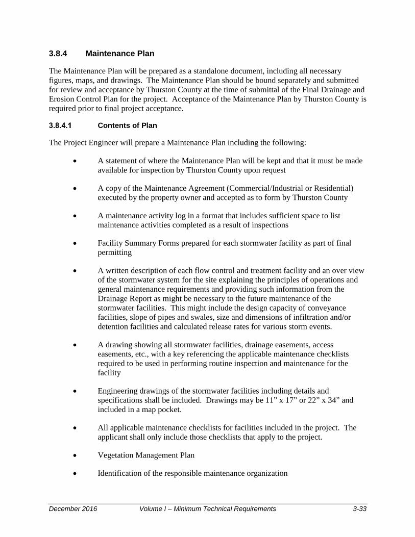
December 2016 Volume I – Minimum Technical Requirements 3-33
3.8.4 Maintenance Plan
The Maintenance Plan will be prepared as a standalone document, including all necessary figures, maps, and drawings. The Maintenance Plan should be bound separately and submitted for review and acceptance by Thurston County at the time of submittal of the Final Drainage and Erosion Control Plan for the project. Acceptance of the Maintenance Plan by Thurston County is required prior to final project acceptance.
Contents of Plan
The Project Engineer will prepare a Maintenance Plan including the following:
• A statement of where the Maintenance Plan will be kept and that it must be made available for inspection by Thurston County upon request
• A copy of the Maintenance Agreement (Commercial/Industrial or Residential) executed by the property owner and accepted as to form by Thurston County
• A maintenance activity log in a format that includes sufficient space to list maintenance activities completed as a result of inspections
• Facility Summary Forms prepared for each stormwater facility as part of final permitting
• A written description of each flow control and treatment facility and an over view of the stormwater system for the site explaining the principles of operations and general maintenance requirements and providing such information from the Drainage Report as might be necessary to the future maintenance of the stormwater facilities. This might include the design capacity of conveyance facilities, slope of pipes and swales, size and dimensions of infiltration and/or detention facilities and calculated release rates for various storm events.
• A drawing showing all stormwater facilities, drainage easements, access easements, etc., with a key referencing the applicable maintenance checklists required to be used in performing routine inspection and maintenance for the facility
• Engineering drawings of the stormwater facilities including details and specifications shall be included. Drawings may be 11” x 17” or 22” x 34” and included in a map pocket.
• All applicable maintenance checklists for facilities included in the project. The applicant shall only include those checklists that apply to the project.
• Vegetation Management Plan
• Identification of the responsible maintenance organization

December 2016 Volume I – Minimum Technical Requirements 3-34
• A description of the required maintenance frequency for each facility
• A description of required recordkeeping and reports and frequency of submittal of reports to Thurston County
• An estimate of the average annual cost of maintenance will be included. The annual cost shall include the annualized cost of major maintenance items such as sediment removal from ponds, etc.
• A pollution source control plan per Volume IV. Language that prohibits unauthorized modifications, unless approved by the County
• Language that provides for a county approval process and allows modification to the covenant, or to the Maintenance and Source Control Manual
• Language that provides for a county process (remedies) for situations where the responsible party fails to perform the required maintenance or fails to implement the pollution source control measures
• Language that provides access authority to the County for purposes of inspection, maintenance, and repair
• Language that provides for reimbursement to the County by the responsible party in the event that the County incurs costs related to maintenance or repair
See Appendix V-C and Appendix I-E for additional guidance.
Identify Organization Responsible for Maintenance
It is Thurston County’s policy that the property owner(s) shall maintain storm drainage facilities, or in the case of a subdivision, the POA shall maintain drainage facilities. The Maintenance Plan shall be prepared to Thurston County’s specifications and held by the property owner or for a subdivision, included by reference in the articles of incorporation of the Property Owners Association.
Vegetation Management Plan
A vegetation management plan shall be included in the Stormwater Facilities Maintenance Plan for the project and shall include recommended plantings for each stormwater facility and specifications for maintenance and replacement plantings. The effectiveness of many stormwater facilities will depend on the species planted in them and their proper maintenance. Consult Appendix V-E regarding proper species for the design condition and for their requirements for maintenance.
Pollution Source Control
Pollution source control is the application of pollution prevention practices on a developed site to reduce contamination of stormwater runoff at its source. Best management practices (BMPs)

December 2016 Volume I – Minimum Technical Requirements 3-35
and resource management systems are designed to reduce the amount of contaminants used or discharged to the environment.
The Maintenance Plan shall contain language regarding pollution source control that is specifically developed for the type of site covered by the plan. The pollution source control section of the plan shall incorporate the relevant information found in Volume IV of this Manual, unless otherwise accepted by the Administrator or designee.
Annual Report Required
The owner shall submit an annual report to Thurston County by August 31st of each calendar year to include, at a minimum, the following:
• Name, address, and telephone number of the businesses, persons, or firms responsible for plan implementation, and the person completing the report
• Time period covered by the report
• A chronological summary of activities conducted to implement the programs required by the Maintenance Plan. A photocopy of the applicable section of the log book, with any additional explanation needed, shall normally suffice. For any activities conducted by paid parties, include a copy of the invoice for services.
• An outline of planned activities for the next year.
The annual report shall be submitted to the Water Resources Division of the Thurston County Department of Resource Stewardship.
3.8.5 Project Completion Criteria
Inspection Report – Drainage and Erosion Control Plans
For Drainage and Erosion Control Plans, in addition to inspection performed by Thurston County, the applicant must retain a licensed Civil Engineer to inspect or oversee inspection of the project as directed by the Drainage and Erosion Control Plan and/or the Administrator or designee. (See inspection reporting requirements, Appendix I-C.) The Engineer must file a construction inspection report with Thurston County as shown in Appendix I-C before the project is made final. The report will consist of a completed form and sufficient additional text to describe all factors relating to the construction and operation of the system to meet treatment, erosion control, detention/retention, flow control, and conveyance requirements.
The Engineer or his/her designee shall keep records of inspections of drainage and erosion control facilities. Records of inspection shall be submitted to the County upon request at any time during the course of the project.

December 2016 Volume I – Minimum Technical Requirements 3-36
As-Built Submittal – Drainage and Erosion Control Plans
For Drainage and Erosion Control Plans, the Project Engineer shall submit as-built drawings bearing the Project Engineer's seal showing all final locations and elevations, materials, and changes from the design. Final elevations, locations, slopes, grades, roadway alignments, etc. shall be based on a field survey conducted by a licensed professional surveyor and shall be stamped by the surveyor as a record of the final constructed location and elevation of facilities shown. The volume of any ponds, vaults, tanks, etc. included in the design shall be calculated based on the as-built survey and this information shall be noted on the as-built drawing. Changes from the approved plans shall be clearly identified using clouding, bold text or other methods to clearly identify those items that were changed during construction. Note that changes from the accepted plan will be reviewed by the County and may be subject to action by the Administrator or designee.
Phased Projects Submittals – Drainage and Erosion Control Plans
A plan showing the overall project, clearly delineating phase boundaries, and estimating dates of construction, shall be part of any initial submittal. Phased projects shall be completed in accordance with accepted plans and in accordance with standard phased development requirements for Thurston County. The thresholds of Chapter 2 shall apply to the entire development including all phases.
3.9 Additional Submittal Information 3.9.1 Qualifications of Project Engineers
The Project Engineer responsible for completion of Drainage and Erosion Control Plans and Engineered Abbreviated Drainage Plans shall be a Civil Engineer with a current State of Washington Professional Engineer's license. All plans and specifications, calculations, construction inspection reports, and all other submittals which will become part of the permanent record of the Project must bear the Project Engineer's official seal.
3.9.2 Review and Acceptance Does Not Confer Responsibility
Thurston County will review all drainage related submittals for general compliance with specific criteria. Acceptance by the County does not relieve the applicant or Project Engineer of responsibility for ensuring that all facilities are safe and that calculations, plans, specifications, construction, and as-built drawings comply with normal engineering standards, this Manual, and applicable federal, state, and local laws and codes.
3.9.3 Time Limitations of Acceptance for Plans
Drainage and Erosion Control Plans and Abbreviated Drainage Plans shall expire when acceptance for the permitted activity (e.g., preliminary plat, clearing, grading, building permit) expires. After expiration, a new Drainage and Erosion Control Plan must be completed subject to conditions and requirements applicable at that time.

December 2016 Volume I – Minimum Technical Requirements 3-37
3.9.4 Aesthetic Considerations
Drainage facilities shall be made attractive features of the urban environment. Engineers are encouraged to be creative in shaping and landscaping facilities and to consider aesthetics when choosing design alternatives (e.g., parking lot paving, conveyance systems, detention facilities, weirs, check structures). See Volume V and Appendix V-E for aesthetic and landscaping criteria.
The applicant shall provide an informational sign for all aboveground stormwater facilities located within the development tract. The sign for storm ponds shall be constructed and worded as specified in Appendix V-E. Other stormwater facilities including swales, rain gardens, dispersion areas, etc. shall also include signage and fencing identifying the area as a stormwater facility and not to disturb. Individual BMPs also include requirements for signage and fencing. See Volume V for more information.
3.9.5 Drainage Plans for Environmentally Sensitive Areas
Development in an Environmentally Sensitive Area
Where buffer zones have been established by the County to restrict development near an environmentally sensitive area or critical area, the applicant shall obtain and implement the requirements of those regulations in addition to any requirements of this Manual.
Acceptance of Dedication of Buffers
Buffers for natural drainage features can provide water quality benefits. Consult the jurisdiction regarding their policy on acceptance of buffers.
3.9.6 Easements and Access
Easements for Natural Channels and Stormwater Facilities
All man-made drainage facilities, conveyances, and all natural channels (including swales, stream channels, lake shores, wetlands, potholes, estuaries, gullies, ravines, etc.) shall be located within easements. Easements shall contain the natural features and facilities and shall allow jurisdiction access to them for purposes of inspection, maintenance, flood control, water quality monitoring, and other activities permitted by law.
Easements for Access
Specific access requirements for ponds are included in Volume V, Appendix V-E. Generally a minimum 15-foot wide access easement shall be provided to drainage facilities from a public street or right-of-way and shall provide a 12-foot minimum width drivable path surfaced with lattice block pavement, crushed rock, or other acceptable surface to allow year-round equipment access to the facility. The easement shall include easement boundary markers which shall be fiberglass utility markers with a reflective easement tag, located at each corner of the easement, at angle points and at least every 100 feet along the length of the easement. Contact Thurston County Water Resources Division for additional information on easement marker requirements.
Easements for Conveyance Systems
Easement requirements for conveyance systems are described in Volume III, Section 3.6.2.

December 2016 Volume I – Minimum Technical Requirements 4-1
Stormwater BMP Selection Process This chapter aids in the selection of appropriate LID, infiltration, flow control, and runoff treatment BMPs to meet Core Requirements #5 (Onsite measures), 6 (Runoff Treatment), and 7 (Flow Control). This chapter is organized as follows:
• Section 4.1: Types of BMPs and satisfying Core Requirement
• Section 4.2: Step-by-step process for determining the level of treatment and flow control and selecting BMPs
• Section 4.3: Supplemental information for selecting and applying oil control BMPs
• Section 4.4: Supplemental information for selecting and applying phosphorus treatment BMPs
• Section 4.5: Supplemental information for selecting and applying enhanced treatment BMPs
• Section 4.6: Supplemental information for selecting and applying basic treatment BMPs
• Section 4.7: Additional treatment facility selection factors, including pollutants of concern and BMPs for specific land uses.
4.1 Introduction
Thurston County’s pollution control strategy is to emphasize pollution prevention first, through the application of source control BMPs. Then the application of appropriate on-site, treatment, and flow control facilities fulfills the statutory obligation to provide AKART, or “all known available and reasonable methods by industries and others to prevent and control the pollution of the waters of the State of Washington.” (RCW 90.48.010) Stormwater BMPs described in this chapter focus on reducing or mitigating the hydrologic and water quality impacts of development. These BMPs address the following Core Requirements:
Core Requirement #5: Onsite Stormwater Management
• LID BMPs are site design and stormwater management techniques that seek to minimize the stormwater impacts of development by mimicking natural hydrologic processes. LID BMPs are required if feasible. See Appendix III-D, Volume III for LID feasibility criteria.
• Onsite BMPs are measures to protect soils and control roof drainage and other runoff to prevent stormwater from leaving the site as much as possible.

December 2016 Volume I – Minimum Technical Requirements 4-2
Core Requirement #6: Runoff Treatment
• Basic treatment BMPs remove sediment from the water column to prevent sedimentation of receiving waters and the adverse effects of sedimentation on fish and amphibians. Sediments can also carry other pollutants, and sediment removal reduces the level of these other pollutants in the runoff.
• Enhanced treatment BMPs provide a greater degree of removal of dissolved metals than “basic” runoff treatment BMPs. (Dissolved metals are toxic to salmon and other endangered species.)
• Phosphorus treatment BMPs include larger wet pond facilities, media filtration BMPs, and treatment trains intended to reduce total phosphorus concentrations in nutrient-sensitive lakes and streams.
• Oil control BMPs remove non-polar, hydrophobic substances (oil and grease) from stormwater by trapping the floating material with baffles or other physical barriers or by filtration through filter media or compost amended biofiltration swales. They are required for high use sites.
Core Requirement #7: Flow Control
• Flow control BMPs are infiltration and/or detention BMPs that control the hydrologic impacts of stormwater by matching predevelopment peak flows, flow durations, and levels of infiltration.
• Applying LID and on-site BMPs within a threshold discharge area is encouraged and may decrease the size of or eliminate the need for traditional flow control BMPs.
Selection of construction-phase stormwater pollution prevention BMPs to meet Core Requirement #2 is described in Volume II. Selection of post-construction source control BMPs to meet Core Requirement #3 is described in Volume IV.
4.2 Step-by-Step BMP Selection Process
Selecting appropriate BMPs for a project site requires knowledge of:
• The receiving water(s) of the project site’s discharge
• Whether Thurston County, Ecology, or the EPA have identified the receiving water as subject to phosphorus control requirements
• Site conditions that may require oil control or enhanced runoff treatment.
Figure 4-1, Figure 4-2, Figure 4-3, and Figure 4-4 illustrates the BMP selection process. The steps of this process are described in detail below.
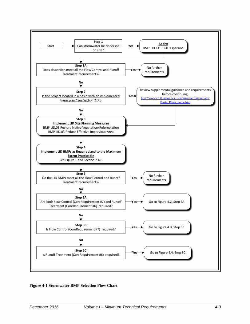
December 2016 Volume I – Minimum Technical Requirements 4-3
Start
Step 2Is the project located in a basin with an implemented
basin plan? See Section 2.3.3Yes
Step 3Implement LID Site Planning Measures
BMP LID.01 Restore Native Vegetation/ReforestationBMP LID.03 Reduce Effective Impervious Area
Review supplemental guidance and requirements before continuing.
http://www.co.thurston.wa.us/stormwater/BasinPlans/Basin_Plans_home.htm
No
Step 4Implement LID BMPs as Required and to the Maximum
Extent PracticableSee Figure 1 and Section 2.4.6
Step 5AAre both Flow Control (CoreRequirement #7) and Runoff
Treatment (CoreRequirement #6) required?
No
Step 5Do the LID BMPs meet all the Flow Control and Runoff
Treatment requirements?
No further requirementsYes
Step 1Can stormwater be dispersed
on site?
Apply:BMP LID.11 – Full Dispersion
Step 1ADoes dispersion meet all the Flow Control and Runoff
Treatment requirements?
Yes
Yes
No
No further requirements
Go to Figure 4.2, Step 6A
Step 5BIs Flow Control (CoreRequirement #7) required?
Step 5CIs Runoff Treatment (CoreRequirement #6) required?
Go to Figure 4.3, Step 6B
Go to Figure 4.4, Step 6C
Yes
No
Yes
No
Yes
Figure 4-1 Stormwater BMP Selection Flow Chart

December 2016 Volume I – Minimum Technical Requirements 4-4
Use one or more of the following:BMP WP.04 – Combined Wet/Detention PondBMP WP.05 – Combined Stormwater Wetland/
Detention Pond
Use one or more of the following:BMP IN.01 – Infiltration Basin*
BMP IN.02 – Infiltration Trench*BMP IN.08 – Bioretention
Is infiltration feasible? See Site Criteria and Infiltration Feasibility Checklist.
Yes
Are Flow Control and Runoff Treatment requirements met?
No
No
Step 7AAre Combined Treatment/Detention BMPs
feasible to meet Treatment and Flow Control requirements?
Yes
No further requirementsYes
YesAre Flow Control and Runoff Treatment
requirements met?
Is additional Runoff Treatment (Core Requirement #6) required?
Step 8AIs additional Flow Control (Core Requirement
#7) required?No
No
Use one or more of the following:BMP D.01 – Detention BasinBMP D.02 – Detention TankBMP D.03 – Detention Vault
BMP D.03 – Using Parking Lots for Detention
Yes
See Figure 4.4. Step 7C
Yes
No further requirements
Step 6AAre both Flow Control (Core Requirement #7) and Runoff
Treatment (Core Requirement #6) required?
Yes
No
*Check Step 7A. Apply pretreatment if Oil Control is required.
Figure 4-2 Stormwater BMP Selection Process Flow Chart, Flow Control and Runoff Treatment
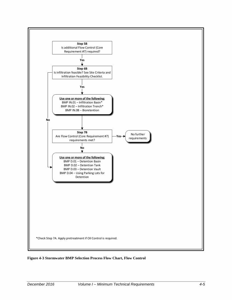
December 2016 Volume I – Minimum Technical Requirements 4-5
Step 5BIs additional Flow Control (Core
Requirement #7) required?
Use one or more of the following:BMP IN.01 – Infiltration Basin*
BMP IN.02 – Infiltration Trench*BMP IN.08 – Bioretention
Yes
Yes
Use one or more of the following:BMP D.01 – Detention BasinBMP D.02 – Detention TankBMP D.03 – Detention Vault
BMP D.04 – Using Parking Lots for Detention
No
Step 6BIs infiltration feasible? See Site Criteria and
Infiltration Feasibility Checklist.
Step 7BAre Flow Control (Core Requirement #7)
requirements met?
No
No further requirementsYes
*Check Step 7A. Apply pretreatment if Oil Control is required.
Figure 4-3 Stormwater BMP Selection Process Flow Chart, Flow Control

December 2016 Volume I – Minimum Technical Requirements 4-6
Step 5CIs additional Runoff Treatment (Core
Requirement #6) required?
No further requirementsNo
Yes
Use one or more of the following:BMP IN.01 – Infiltration Basin*
BMP IN.02 – Infiltration Trench*BMP IN.08 – Bioretention
Step 8CIs drainage area a “High
Use Site”
Step 9CIs phosphorous control
required?
Step 10C Is enhanced treatment
required?
Yes
No
Use one or more of the following:BMP OW.01 – API (Baffle Type) Separator BayBMP OW.02 - Coalescing Plate Separator Bay
BMP BF.04 - Compost Amended Vegetated Filter StripBMP MF.03 – Linear Sand Filter
Use one or more of the following:BMP WP.02 – Wet pond (large)
BMP MF.01 – Sand Filter Basin (Large Option)BMP MF.02 – Sand Filter Vault (Large Option)BMP MW.03 Linear Sand Filter (Large Option)
BMP MF.04 – Media Filter DrainTreatment Train
Experimental Media Filtration (Amended or Alternate Media)+
YesNo
Use one or more of the following:BMP BF.04 – Compost Amended Vegetated Filter Strip
BMP MF.01 – Sand Filter Basin (Large Option)BMP MF.02 – Sand Filter Vault (Large Option)BMP MW.03 Linear Sand Filter (Large Option)
BMP MF.04 – Media Filter DrainBMP WP.04 – Stormwater Treatment Wetland
Treatment TrainExperimental Media Filtration (Amended or Alternate Media)+
Yes
Use one or more of the following:BMP BF.01 – BF.04 Swales and Filter Strips
BMP WP.01 – WP.04 – Wet Pool BMPsBMP MF.01 – MF.04 – Media Filter BMPs
No
Step 6CIs infiltration feasible? See Site Criteria
and Infiltration Feasibility Checklist.
Yes
Step 7CAre Runoff Treatment (Core
Requirement #6) requirements met?
No
No further requirementsYes
*Check Step 7A. Apply pretreatment if Oil Control is required.+Requires Drainage Manual Administrator approval.
Figure 4-4 Stormwater BMP Selection Process Flow Chart, Runoff Treatment

December 2016 Volume I – Minimum Technical Requirements 4-7
4.2.1 Step 1: Determine if Stormwater can be Dispersed On Site
Can full dispersion be used to treat stormwater?
If yes, apply BMP LID.11 – Full Dispersion to the site.
Step 1A - Check to see if Full Dispersion meets all the Flow Control (Core Requirement #7) and Runoff Treatment (Core Requirement #6), if so, there are no further requirements.
If No, go to Step 2.
4.2.2 Step 2: Determine if the Project Site is in a Basin with an Implemented Basin Plan
Does Your Project Drain to a Basin with an Implemented Basin Plan?
If so, see the applicable basin plan or the Thurston County basin planning website to determine if there are applicable requirements or restrictions for runoff treatment, flow control, and infiltration. You must meet the more stringent of either of the controls described in this section or those in the basin plan. See the Thurston County basin planning website for more information: <http://www.co.thurston.wa.us/stormwater/BasinPlans/Basin_Plans_home.htm>.
4.2.3 Step 3: Implement LID Site Planning Measures
Thoughtful site design can significantly reduce both the cost and land area required for stormwater management and the hydrologic and water quality impacts of your project. Volume V provides ideas for smart design and LID measures to consider and, where feasible, implement at the earliest planning stages. Site planning LID BMPs include:
• BMP LID.01: Restore Native Vegetation
• BMP LID.03: Reduce Effective Impervious Areas Associated with Roads, Shared Accesses, Alleys, Sidewalks, Driveways, and Parking Areas.
4.2.4 Step 4: Implement LID BMPs as Required and to the Maximum Extent Feasible
To meet Core Requirement #5: See Section 2.4.6 to determine the Core Requirement for the project. Check site to determine if LID is feasible and apply the appropriate BMPs from List 1, List 2, or choose to meet the LID Flow Duration Standard.
Roadway projects may use the WSDOT 2014 HRM, or current edition to determine and meet Core Requirement #5 conditions.
4.2.5 Step 5: Determine Applicability of Core Requirements #6 and #7
After implementing LID BMPs, see the Core Requirements (Chapter 2 of this volume) to determine whether additional flow control (Core Requirement #7) or runoff treatment (Core

December 2016 Volume I – Minimum Technical Requirements 4-8
Requirement #6) BMPs are required. The implementation of LID BMPs will help reduce the amount of flow control runoff treatment facilities required.
Do the LID BMPs meet all the Flow Control and Runoff Treatment Requirements?
If YES, there are no further requirements.
If NO, proceed to Step 5A.
Step 5A, Are Both Flow Control and Runoff Treatment Required?
If YES, proceed to Step 6A.
If NO, proceed to Step 5B.
Step 5B, Is Flow Control Required?
If YES, proceed to Step 6B.
If NO, proceed to Step 5C.
Step 5C, Is Runoff Treatment Required?
If YES, proceed to Step 6C.
4.2.6 Step 6: Select infiltration BMP
Step 6A: Determine Feasibility and Select Infiltration BMP for Both Flow Control and Runoff Treatment
4.2.6.1.1 Is infiltration feasible for your site? Check the Site Suitability Criteria in Volume III, Section 2.3 for hydrologic and soil suitability for runoff treatment criteria in Section 2.3 of Volume III?
If YES, select from the following BMPs to provide both flow control and runoff treatment. Also, check Step 9C to determine if oil control is needed prior to infiltration. If so, select an oil control BMP from the list and implement. However, do not continue to Step 8C at this time. If after implementing one of the following BMPs the discharge to surface water exceeds flow control thresholds, proceed to Step 10A and implement detention BMP to meet flow control requirements:
• BMP IN.01: Infiltration Basins
• BMP IN.02: Infiltration Trenches
• BMP LID.08: Bioretention Facilities.
If NO, proceed to Step 8A.

December 2016 Volume I – Minimum Technical Requirements 4-9
Step 6B: Determine Feasibility and Select Infiltration BMP for Flow Control
4.2.6.2.1 Is infiltration feasible for your site? Check the Site Suitability Criteria in Volume III, Section 2.3 for hydrologic and soil suitability to determine if pretreatment is required.
If YES, select from the following BMPs to provide flow control:
• BMP IN.01: Infiltration Basins
• BMP IN.02: Infiltration Trenches
• BMP IN.04: Bio-Infiltration Swale.
If after implementing one of the above BMPs there is a discharge to surface water that exceeds flow control requirements, proceed to Step 7B and implement detention BMP to meet flow control requirements.
Check Step 8C to determine if pretreatment is required. If pretreatment is required, select runoff treatment BMP(s) located upstream of the infiltration BMP. If not, BMP selection is complete.
If NO, proceed to Step 7A.
If NO and no runoff treatment is required, proceed to Step 6B.
Step 6C: Determine Feasibility and Select Infiltration BMP for Runoff Treatment
4.2.6.3.1 Is infiltration feasible and do your site and soils meet the site suitability and runoff treatment criteria in Section 2.3 of Volume III?
If YES, select from the following BMPs:
• BMP IN.01: Infiltration Basins
• BMP IN.02: Infiltration Trenches
• BMP IN.04: Bio-Infiltration Swale
• BMP LID.08: Bioretention Facilities.
Also, check Step 8C to determine if oil control is needed prior to infiltration. If so, select an oil control BMP from the list and implement. However, do not continue to Step 9C at this time.
If NO, proceed to Step 8C.

December 2016 Volume I – Minimum Technical Requirements 4-10
4.2.7 Step 7: Select Detention BMP
Step 7A: Determine Feasibility and Select Combined Treatment/Flow Control BMP
4.2.7.1.1 Is a combined treatment/flow control BMP feasible?
If YES, select from the following BMPs:
• BMP WP.04: Combined wet/detention pond
• BMP WP.05: Combined stormwater wetland/detention pond.
Proceed to Step 8C to evaluate the need for additional oil control BMPs, and to verify that the combined BMP selected above meets the necessary treatment level.
If NO, proceed to Step 7B.
Step 7B: Select Detention BMP
Select from the following BMPs:
• BMP D.01: Detention Ponds
• BMP D.02: Detention Tanks
• BMP D.03: Detention Vaults
• BMP D.04: Use of Parking Lots for Detention.
If runoff treatment (Core Requirement #6) is required for your project, proceed to Step 7C.
If no runoff treatment is required, BMP selection is complete.
4.2.8 Step 7C: Select Runoff Treatment BMP
Step 8C: Determine Feasibility and Select Oil Control BMP
4.2.8.1.1 Is your project a “high use site”?
“High use” sites include:
• An area of a commercial or industrial site subject to an expected average daily traffic (ADT) count equal to or greater than 100 vehicles per 1,000 square feet of gross building area (see Section 4.3 for guidance on estimating traffic counts)
• An area of a commercial or industrial site subject to petroleum storage and transfer in excess of 1,500 gallons per year, not including routinely delivered heating oil

December 2016 Volume I – Minimum Technical Requirements 4-11
• An area of a commercial or industrial site subject to parking, storage or maintenance of 25 or more vehicles that are over 10 tons gross weight (trucks, buses, trains, heavy equipment, etc.)
• A road intersection with a measured average daily traffic (ADT) count of 25,000 vehicles or more on the main roadway and 15,000 vehicles or more on any intersecting roadway, excluding projects proposing primarily pedestrian or bicycle use improvements.
Section 4.3 has supplemental information on oil control, including land uses that are likely to have areas that fall within the definition of “high use sites”.
If YES, select one of the following BMPs and proceed to Step 8B:
• BMP OW.01: API (Baffle type) Separator Bay
• BMP OW.02: Coalescing Plate (CP) Separator Bay
• BMP OW.03: Oil Containment Booms. (not allowed for private development)
Alternately, the following BMPs can be used to meet oil control requirements and other treatment levels. If these BMPs are selected, steps 9C, and 10C must be completed to ensure that they meet the appropriate level of treatment:
• BMP MF.03: Linear Sand Filter (if amended to provide phosphorus treatment)
• BMP WP.03: Wet vaults (if designed to include a baffle)
• BMP BF.04: Compost-Amended Vegetated Filter Strip.
If NO, proceed to Step 9C.
Step 9: Phosphorus Control BMP
The following Thurston County lakes are reported under Section 305(b) of the Clean Water Act and designated as not supporting beneficial uses due to phosphorus.
• Black Lake
• Capitol Lake
• Clear Lake
• Lawrence Lake
• Long Lake
• Pattison Lake (south arm).
December 2016 Volume I – Minimum Technical Requirements 4-12
Projects within any of these lakes’ basins will be required to provide phosphorus treatment, unless a TMDL or County-approved lake management plan specifically identified phosphorus treatment as unnecessary.
Phosphorous treatment is also required for any projects meeting the thresholds for requiring runoff treatment in the Woodard Creek Basin.
If there is no lake management plan or TMDL for one of the above water bodies, and your project has the potential to contribute phosphorus to it (e.g., landscaped areas that will be fertilized, bare soils that could be transported off-site), phosphorus treatment is required. Section 4.4 has more information about phosphorous treatment requirements and BMPs.
If phosphorus treatment is required, select and apply a phosphorous treatment facility from the list below:
• BMP MF.04: Media Filter Drain
• BMP MF.01: Sand Filter Basin (if amended to provide phosphorus treatment)
• BMP MF.03: Linear Sand Filter (if amended to provide phosphorus treatment)
• BMP MF.02: Sand Filter Vault (if amended to provide phosphorus treatment)
• BMP WP.02: Wet ponds (if designed to be a large wet pond)
• BMP WP.03: Wet vaults (if designed to be a large wet vault)
• BMP WP.04: Combined detention/wet pool facilities (if designed with a large wet pool).
Note: Project sites subject to the Phosphorus Treatment requirement could also be subject to the Enhanced Treatment requirement (see Step 10C). In that event, apply a facility or a treatment train that is listed both above and under Step 10C. Infiltration treatment also provides phosphorous treatment.
Proceed to Step 10C.
Step 10C: Enhanced Treatment BMP
4.2.8.3.1 Does your project provide infiltration within a designated Well Head Protection Area for a public water supply serving over 1,000 connections?
If NO, proceed to next question. If YES, select enhanced treatment BMPs per the list at the end of Step 7C.
4.2.8.3.2 Does your project discharge to fish-bearing streams, lakes, or to waters or conveyance systems tributary to fish-bearing streams or lakes?
December 2016 Volume I – Minimum Technical Requirements 4-13
If NO, Apply Basic Treatment BMPs.
If YES, proceed to next question.
4.2.8.3.3 Does your project drain directly (or, indirectly through a municipal storm sewer system) to a salt water body?
If YES, Apply Basic Treatment BMPs.
If NO:
4.2.8.3.4 Does your project include any of the following?
• Infiltration facility within a designated Well Head Protection Area for a public water supply serving over 1,000 connections.
• Industrial project sites,
• Commercial project sites,
• Multi-family project sites, and
• High Annual Average Daily Traffic (AADT) roads as follows:
Within Urban Growth Management Areas:
− Fully controlled and partially controlled limited access highways with AADT counts of 15,000 or more
− All other roads with an AADT of 7,500 or greater
Outside of Urban Growth Management Areas:
− Roads with an AADT of 15,000 or greater unless discharging to a 4th Strahler order stream or larger
− Roads with an AADT of 30,000 or greater if discharging to a 4th Strahler order stream or larger (as determined using 1:24,000 scale maps to delineate stream order).
However, areas of the project sites listed above that are identified as subject to Basic Treatment requirements (see Section 4.6) are also not subject to Enhanced Treatment requirements. For developments with a mix of land use types, the Enhanced Treatment requirement shall apply when the runoff from the areas subject to the Enhanced Treatment requirement comprises 50 percent or more of the total runoff within a threshold discharge area. See Section 4.5 for more information on Enhanced Treatment.
If YES, select enhanced treatment BMPs for your site or for those areas subject to enhanced treatment BMPs.

December 2016 Volume I – Minimum Technical Requirements 4-14
• BMP LID.08: Bioretention Facilities
• BMP BF.04: Compost-Amended Vegetated Filter Strip
• BMP WP.01: Stormwater treatment wetland
• BMP MF.04: Media Filter Drain
• BMP MF.01: Sand Filter Basin (if amended to provide enhanced treatment)
• BMP MF.03: Linear Sand Filter (if amended to provide enhanced treatment)
• BMP MF.02: Sand Filter Vault (if amended to provide enhanced treatment).
Basic Treatment BMP
The following are options for basic treatment BMPs:
• BMP BF.01: Basic Biofiltration Swale
• BMP BF.02: Wet Biofiltration Swale
• BMP BF.03: Continuous Inflow Biofiltration Swale
• BMP BF.04: Basic Filter Strip
• BMP BF.05: Narrow area filter strip
• BMP WP.01: Stormwater treatment wetland
• BMP WP.02: Wet ponds
• BMP WP.03: Wet vaults
• BMP WP.04: Combined detention/wet pool facilities
• Any BMP providing enhanced treatment.
This completes the treatment facility selection process.
4.3 Oil Control BMPs: Supplemental Information
4.3.1 Applicability
The traffic count (to determine whether a site is considered “high use”) can be estimated using information from Trip Generation, published by the Institute of Transportation Engineers, or from a traffic study prepared by a professional engineer or transportation specialist with experience in traffic estimation.

December 2016 Volume I – Minimum Technical Requirements 4-15
The following urban land uses are likely to have areas that fall within the definition of “high use sites” or have sufficient quantities of free oil present that can be treated by an API or CP-type oil and water separator:
• Industrial Machinery and Equipment, and Railroad Equipment Maintenance
• Log Storage and Sorting Yards
• Aircraft Maintenance Areas
• Railroad Yards
• Fueling Stations
• Vehicle Maintenance and Repair
• Construction Businesses (paving, heavy equipment storage and maintenance, storage of petroleum products).
Oil control facilities should also be used on other sites that generate high concentrations of oil. All-day parking areas are not intended to be defined as high use sites and should not require the oil control options listed in this menu. Gasoline stations, with or without small food stores, will likely exceed the high use site threshold. The petroleum storage and transfer criterion is intended to address regular transfer operations such as gasoline service stations, not occasional filling of heating oil tanks.
4.3.2 Application on the Project Site
Oil control facilities are to be placed upstream of other facilities, as close to the source of oil generation as possible. For high use sites located within a larger commercial center, only the impervious surface associated with the high use portion of the site is subject to treatment requirements. If common parking for multiple businesses is provided, treatment shall be applied to the number of parking stalls required for the high use business only. However, if the treatment collection area also receives runoff from other areas, the treatment facility must be sized to treat all water passing through it.
High use roadway intersections shall treat lanes where vehicles accumulate during the signal cycle, including left and right turn lanes and through lanes, from the beginning of the left turn pocket. If no left turn pocket exists, the treatable area shall begin at a distance equal to three car lengths from the stop line. If runoff from the intersection drains to more than two collection areas that do not combine within the intersection, treatment may be limited to any two of the collection areas.
4.3.3 Performance Goal
The facility choices in the Oil Control Menu are intended to achieve the goals of no ongoing or recurring visible sheen, and to have a 24-hour average Total Petroleum Hydrocarbon (TPH)

December 2016 Volume I – Minimum Technical Requirements 4-16
concentration no greater than 10 mg/l, and a maximum of 15 mg/l for a discrete sample (grab sample).
Note: Use the method for NWTPH-Dx in Ecology Publication No. ECY 97-602, Analytical Methods for Petroleum Hydrocarbons to determine oil concentrations. If the concentration of gasoline is of interest, the method for NWTPH-Gx should be used to analyze grab samples.
4.3.4 Oil Control Menu
Options
Oil control options include facilities that are small, treat runoff from a limited area, and require frequent maintenance. The options also include facilities that treat runoff from larger areas and generally have less frequent maintenance needs.
• BMP OW.01: API-Type Oil/Water Separator
• BMP OW.02: Coalescing Plate Oil/Water Separator
• BMP MF.03: Linear Sand Filter
• BMP BF.04: Compost-Amended Vegetated Filter Strip.
• BMP WP.03: Wet vaults (if designed to include a baffle).
Note: The linear sand filter is also used in the Basic, Enhanced, and Phosphorus Treatment menus. If used to satisfy one of those treatment requirements, the same facility shall not also be used to satisfy the oil control requirement, unless enhanced maintenance is assured. This is to prevent clogging of the filter by oil so that it will function for both suspended solids and phosphorus removal. Quarterly cleaning is required unless otherwise specified by the designer.
4.4 Phosphorus Treatment: Supplemental Information
4.4.1 Where Applied
The Phosphorus Treatment Menu (below) applies to projects within watersheds determined by local governments, the Department of Ecology, or the USEPA to be sensitive to phosphorus, and that are being managed to control phosphorus inputs from stormwater. This menu applies to stormwater conveyed to the lake by surface flow and to stormwater infiltrated within one-quarter mile of the lake in soils that do not meet soil suitability criteria described in Volume III, Chapter 3.
4.4.2 Performance Goal
The Phosphorus Menu facility choices are intended to achieve a goal of 50 percent total phosphorus removal for a range of influent concentrations of 0.1 – 0.5 mg/l total phosphorus. The choices are also intended to achieve the Basic Treatment performance goal. The performance goal applies to the water quality design storm volume or flow rate, whichever is

December 2016 Volume I – Minimum Technical Requirements 4-17
applicable, and on an annual average basis. The incremental portion of runoff in excess of the water quality design flow rate or volume can be routed around the facility (offline treatment facilities), or can be passed through the facility (online treatment facilities) provided a net pollutant reduction is maintained. Ecology encourages the design and operation of treatment facilities that engage a bypass at flow rates higher than the water quality design flow rate. Note that wet pool facilities are always designed to be online.
4.4.3 Phosphorus Treatment Menu
Any one of the following options may be chosen to satisfy the phosphorus treatment requirement.
• Infiltration with appropriate pretreatment:
Infiltration treatment: If infiltration is through soils meeting the minimum site suitability criteria for infiltration treatment (see Section 2.3 of Volume III and Volume V), a presettling basin or a basic treatment facility can serve for pretreatment.
Infiltration preceded by Basic Treatment: If infiltration is through soils that do not meet the soil suitability criteria for infiltration treatment, treatment must be provided by a basic treatment facility unless the soil and site fit the description in the next option below.
Infiltration preceded by Phosphorus Treatment: If the soils do not meet the soil suitability criteria and the infiltration site is within 1/4 mile of a phosphorus-sensitive receiving water, or a tributary to that water, treatment must be provided by one of the other treatment facility options listed below.
• BMP MF.01 or MF.02: Large Sand Filter
• BMP MF.01 or MF.02: Amended Sand Filter (sand filter amendment requires Drainage Manual Administrator acceptance from Thurston County)
Note: Processed steel fiber and crushed calcitic limestone are the only sand filter amendments for which Ecology has data that documents increased dissolved metals removal. The use of processed steel fiber has been reported to cause a number of maintenance problems as it oxidizes over time and decreases the design filtration rate.
• BMP WP.02: Large Wet Pond
• Media Filter targeted for phosphorus removal (Drainage Manual Administrator acceptance required)
• Two-Facility Treatment Trains – see Table 4-1.

December 2016 Volume I – Minimum Technical Requirements 4-18
Table 4-1 Treatment Trains for Phosphorus Removal
First Basic Treatment Facility Second Treatment Facility
BMP BF.01 Biofiltration Swale BMP MF.01 Sand Filter Basin or BMP MF.02 Sand Filter Vault
BMP BF.04 Filter Strip BMP MF.03 Linear Sand Filter (no presettling needed)
BMP MF.03 Linear Sand Filter BMP BF.04 Filter Strip
BMP WP.02 Basic Wet Pond BMP MF.01 Sand Filter Basin or BMP MF.02 Sand Filter Vault
BMP WP.03 Wet Vault BMP MF.01 Sand Filter Basin or BMP MF.02 Sand Filter Vault
BMP WP.01 Stormwater Treatment Wetland BMP MF.01 Sand Filter Basin or BMP MF.02 Sand Filter Vault
BMP WP.04 Basic Combined Detention and Wet Pool
BMP MF.01 Sand Filter Basin or BMP MF.02 Sand Filter Vault
4.5 Enhanced Treatment: Supplemental Information
4.5.1 Performance Goal
The Enhanced Menu facility choices (below) are intended to provide a higher rate of removal of dissolved metals than Basic Treatment facilities. .
The choices are also intended to achieve the Basic Treatment performance goal. This performance goal assumes that the facility is treating stormwater with dissolved Copper typically ranging from 0.003 to 0.02 mg/l, and dissolved Zinc ranging from 0.02 to 0.3 mg/l.
The performance goal applies to the water quality design storm volume or flow rate, whichever is applicable, and on an annual average basis. The incremental portion of runoff in excess of the water quality design flow rate or volume can be routed around the facility (off-line treatment facilities), or can be passed through the facility (on-line treatment facilities) provided a net pollutant reduction is maintained. Ecology encourages the design and operation of treatment facilities that engage a bypass at flow rates higher than the water quality design flow rate as long as the reduction in dissolved metals loading exceeds that achieved with initiating bypass at the water quality design flow rate. Note that wet pool facilities are always designed to be on-line.
4.5.2 Enhanced Treatment Menu
Any one of the following options may be chosen to satisfy the enhanced treatment requirement:
Note: If phosphorous treatment is also required, select a facility or facility train that meets both Enhanced and Phosphorous treatment.
• Infiltration with appropriate pretreatment (see Volume III and Volume V)
Infiltration treatment: If infiltration is through soils meeting the minimum site suitability criteria for infiltration treatment (see Volume III and Volume V), a presettling basin or a basic treatment facility can serve for pretreatment.

December 2016 Volume I – Minimum Technical Requirements 4-19
Infiltration preceded by Basic Treatment: If infiltration is through soils that do not meet the soil suitability criteria for infiltration treatment, treatment must be provided by a basic treatment facility unless the soil and site fit the description in the next option below.
Infiltration preceded by Enhanced Treatment: If the soils do not meet the soil suitability criteria and the infiltration site is within a designated well head protection area or within 1/4 mile of a fish-bearing stream, a tributary to a fish-bearing stream, or a lake, treatment must be provided by one of the other treatment facility options listed below.
• BMP MF.01 or BMP MF.02: Large Sand Filter
• BMP MF.01 or BMP MF.02: Amended Sand Filter (sand filter amendment requires Drainage Manual Administrator acceptance from Thurston County)
• BMP WP.01: Stormwater Treatment Wetland
• BMP BF.04: Compost-amended Filter Strip
• Compost Amended Biofiltration Swale
• Two Facility Treatment Trains – see Table 4-2
Table 4-2 Treatment Trains for Dissolved Metals Removal First Basic Treatment Facility Second Treatment Facility
Biofiltration Swale Basic Sand Filter or Sand Filter Vault or Media Filter 1
Filter Strip Linear Sand Filter with no pre-settling cell needed
Linear Sand Filter Filter Strip
Basic Wet Pond Basic Sand Filter or Sand Filter Vault or Media Filter 1
Wet Vault Basic Sand Filter or Sand Filter Vault or Media Filter 1
Basic Combined Detention/Wet Pool Basic Sand Filter or Sand Filter Vault or Media Filter 1
Basic Sand Filter or Sand Filter Vault with a presettling cell if the filter isn’t preceded by a detention facility
Media Filter 1
1 The media must be of a nature that has the capability to remove dissolved metals effectively based on at least limited data. Ecology includes Stormfilter’s ™ leaf compost and zeolite media in this category.
• BMP LID.08: Bioretention Facility
Note: Any stormwater runoff that infiltrates through the imported soil mix will have received the equivalent of Enhanced Treatment. Where bioretention/rain gardens are intended to fully meet treatment requirements, they must be designed, using an approved continuous runoff model, to infiltrate 91 percent of the influent runoff file.
• BMP MF.04: Media Filter Drain

December 2016 Volume I – Minimum Technical Requirements 4-20
4.6 Basic Treatment: Supplemental Information
4.6.1 Applicability
The Basic Treatment Menu (below) is applied to:
• Project sites that discharge to the ground, unless:
The soil suitability criteria for infiltration treatment are met (see Section 2.3 of Volume III and Volume V), or
The project uses infiltration strictly for flow control – not treatment – and the discharge is within 1/4 mile of a phosphorus sensitive lake (use the Phosphorus Treatment Menu), or within 1/4 mile of a fish-bearing stream, or a lake (use the Enhanced Treatment Menu).
Facility is located within a designated Well Head Protection Area for a public water supply with 1,000 connections or greater (use the Enhanced Treatment Menu).
• Residential projects not otherwise needing phosphorus control as designated by the EPA, Ecology, or a local government.
• Project sites discharging directly to salt water or basic receiving waters
• Project sites that drain to streams that are not fish-bearing, or to waters not tributary to fish-bearing streams
• Landscaped areas of industrial, commercial, and multi-family project sites, and parking lots of industrial and commercial project sites, dedicated solely to parking of employees’ private vehicles that do not involve any other pollution-generating sources (e.g., industrial activities, customer parking, storage of erodible or leachable material, wastes or chemicals). For developments with a mix of land use types, the Basic Treatment requirement shall apply when the runoff from the areas subject to the Basic Treatment requirement comprises 50 percent or more of the total runoff within a threshold discharge area.
4.6.2 Performance Goal
The Basic Treatment Menu facility choices (below) are intended to remove 80 percent of TSS for influent concentrations that are greater than 100 mg/l, but less than 200 mg/l. For influent concentrations greater than 200 mg/l, a higher treatment goal may be appropriate. For influent concentrations less than 100 mg/l, the facilities are intended to achieve an effluent goal of 20 mg/l TSS.
The performance goal applies to the water quality design storm volume or flow rate, whichever is applicable. The goal also applies on an average annual basis to the entire annual discharge volume (treated plus bypassed). The incremental portion of runoff in excess of the water quality design flow rate or volume can be routed around the facility (off-line treatment facilities), or can be passed through the facility (on-line treatment facilities) provided a net TSS reduction is

December 2016 Volume I – Minimum Technical Requirements 4-21
maintained. Ecology encourages the design and operation of treatment facilities that engage a bypass at flow rates higher than the water quality design flow rate as long as the reduction in TSS loading exceeds that achieved with initiating bypass at the water quality design flow rate. Wet pool facilities are always designed to be online. The performance goal assumes that the facility is treating stormwater with a typical particle size distribution. For a description of a typical particle size distribution, please refer to the stormwater monitoring protocol in “Guidance for Evaluating Emerging Stormwater Treatment Technologies, Technology Assessment Protocol - Ecology (TAPE)” on the Ecology website: <http://www.ecy.wa.gov/biblio/0210037.html>.
4.6.3 Basic Treatment Menu
Any one of the following options may be chosen to satisfy the basic treatment requirement:
• Infiltration (with adequate soils)
• Sand filters
• Biofiltration swales
• Filter strips
• Basic wet pond
• Wet vault
• Stormwater treatment wetland
• Combined detention and wet pool facilities
• Bioretention facilities
Note: For bioretention facilities, any stormwater runoff that infiltrates through the imported soil mix will have received the equivalent of Enhanced Treatment. Where bioretention/rain gardens are intended to fully meet treatment requirements, they must be designed, using an approved continuous runoff model, to infiltrate 91 percent of the influent runoff file.
• Media Filter Drain
• Alternative Technologies when accepted at the “General Use Level” under Ecology’s TAPE program: (for example: CONTECH Stormwater Management StormFilter with ZPGTM media – A canister-type filter with zeolite/perlite/granular activated carbon).
Note: A wet vault may be used for commercial, industrial, or road projects if there are space limitations. Thurston County discourages the use of wet vaults for residential projects. Combined detention/wet vaults are allowed. Any use of a wet vault for basic treatment requires specific authorization and acceptance by Thurston County based on site circumstances.

December 2016 Volume I – Minimum Technical Requirements 4-22
4.7 Other Treatment Facility Selection Factors
Selection of a treatment facility should be based on physical site factors and pollutants of concern. Requirements for using Enhanced Treatment or Phosphorus Treatment represent facility selection based on pollutants of concern. Even if the site is not subject to those requirements, try to choose a facility that has been shown to remove the types of pollutants generated on the site. The types of physical site factors that influence facility selection are summarized below.
4.7.1 Soil Type
The permeability of soil under a treatment facility has a profound influence on the facility’s effectiveness. This is particularly true for infiltration treatment facilities that are best sited in sandy to loamy sand soils, and not generally appropriate for sites that have final infiltration rates of less than 0.5 inches per hour. Wet pond facilities situated on coarser soils will need a synthetic liner or soil amendment to reduce the infiltration rate and provide treatment. Maintaining a permanent pool in the first cell is necessary to avoid resuspension of settled solids. Biofiltration swales in coarse soils can also be amended to reduce the infiltration rate.
4.7.2 High Sediment Input
High TSS loads can clog infiltration soil, sand filters and coalescing plate oil & water separators. Pretreatment with a presettling basin, wet vault, or another basic treatment facility would typically be necessary.
4.7.3 Other Physical Factors
Slope
Steep slopes restrict the use of several BMPs. For example, biofiltration swales are usually situated on sites with slopes of less than 6 percent, although greater slopes can be considered. Infiltration BMPs are not suitable when the slope exceeds 15 percent.
High Water Table
Unless there is sufficient horizontal hydraulic receptor capacity, the water table acts as an effective barrier to exfiltration and can sharply reduce the efficiency of an infiltration system. If the seasonal high water table extends to within 5 feet of the bottom of an infiltration BMP, the site is seldom suitable.
Depth to Bedrock/ Hardpan/Till
The downward exfiltration of stormwater is also impeded if a bedrock or till layer lies too close to the surface. If the impervious layer lies within 5 feet below the bottom of the infiltration BMP, the site is seldom suitable. Similarly, pond BMPs are often not feasible if bedrock lies within the area that must be excavated.

December 2016 Volume I – Minimum Technical Requirements 4-23
Proximity to Foundations and Wells
Since infiltration BMPs convey runoff back into the soil, some sites may experience problems with local seepage. This can be a real problem if the BMP is located too close to a building foundation. Another risk is ground water pollution; hence the requirement to site infiltration systems more than 100 feet away from drinking water wells.
Maximum Depth
Wet ponds are also subject to a maximum depth limit for the "permanent pool" volume. Deep ponds (greater than 8 feet) may stratify during summer and create low oxygen conditions near the bottom resulting in re-release of phosphorus and other pollutants back into the water.

December 2016 Volume I – Minimum Technical Requirements A-1
Appendix I-A Glossary Appendix I-A – See Preface and Table of Contents.
December 2016 Volume I – Minimum Technical Requirements B-1
Appendix I-B Bond Quantities Worksheet
The Bond Quantity Worksheet is available for download as an Excel Spreadsheet on the Thurston County Drainage Design and Erosion Control Manual website at http://www.co.thurston.wa.us/stormwater/manual/manual-home.html. If you need a paper copy, please contact Thurston County Water Resources Division at 360-754-4681.
Bond Quantities Worksheet

THURSTON COUNTY DRAINAGE DESIGN AND EROSION CONTROL MANUAL
December 2016 Volume I – Minimum Technical Requirements C-1
Appendix I-C Engineer’s Construction Inspection Report Form The Engineer’s Construction Inspection Report Form is available for download on the Thurston County Drainage Design and Erosion Control Manual website at http://www.co.thurston.wa.us/stormwater/manual/manual-home.html. If you need a paper copy, please contact Thurston County Water Resources Division at 360-754-4681.
Engineer’s Construction Inspection Report Form

THURSTON COUNTY DRAINAGE DESIGN AND EROSION CONTROL MANUAL
December 2016 Volume I – Minimum Technical Requirements D-1
Appendix I-D Facility Summary Form
The Facility Summary Form is available for download on the Thurston County Drainage Design and Erosion Control Manual website at http://www.co.thurston.wa.us/stormwater/manual/manual-home.html. If you need a paper copy, please contact Thurston County Water Resources Division at 360-754-4681.
Facility Summary Form

THURSTON COUNTY DRAINAGE DESIGN AND EROSION CONTROL MANUAL
December 2016 Volume I – Minimum Technical Requirements E-1
Appendix I-E Maintenance Agreement Forms
The Maintenance Agreement Forms are available for download on the Thurston County Drainage Design and Erosion Control Manual website at http://www.co.thurston.wa.us/stormwater/manual/manual-home.html. If you need a paper copy, please contact Thurston County Water Resources Division at 360-754-4681.
Commercial Stormwater Agreement to Maintain Template Microsoft Word version
Commercial Stormwater Pollution Prevention Source Control Plan Template (PDF) (For a Microsoft Word version, click here)
Stormwater Pollution Prevention Source Control Plan BMPs (Microsoft Word)
Residential Subdivision Agreement to Maintain Template Microsoft Word version
Single Family Residential Agreement to Maintain Template Microsoft Word version

December 2016 Volume I – Minimum Technical Requirements F-1
Appendix I-F Soils Report Forms
SOIL EVALUATION REPORT FORMS
INSTRUCTIONS A geotechnical report and/or soils report is required for the majority of development projects. Specific requirements are described throughout the DDECM. Specific instances when a geotechnical report and/or soil report is required include:
• All projects for which a Drainage and Erosion Control Plan is required.
• To establish field-saturated percolation rates for stormwater facilities and the overall site.
• For characterizing the infiltration receptor when an infiltration facility is proposed for the project.
• For establishing parameters for the performance of a groundwater mounding analysis, if required.
• To support the design of structures, retaining walls and other site features associated with securing a building permit.
• To support the construction of roads, parking areas, etc. as part of the overall project design process.
• For sites with slopes greater than 15% to determine suitability for locating facilities and/or determining whether a landslide hazard exists and addressing the effects of seepage and potential for slope failure.
• As required for grading work per Thurston County Code Chapter 14.31, International Building Code Appendix J, Grading.
When completing a geotechnical/soils report, the forms in this Appendix shall be included in the report as follows:
• Form 1: General Site Information: One copy of this completed form will be included at the front of the report.
• Form 2: Soil Log Evaluation: One copy of Form 2 shall be completed and included for each soil location where testing has been done.
Where inadequate space is provided, reference attached supplemental documents or prepare separate report in format that includes each of the headings of Form 1

December 2016 Volume I – Minimum Technical Requirements F-2
SOIL EVALUATION REPORT FORM 1: GENERAL SITE INFORMATION
PROJECT TITLE: SHEET OF PROJECT NO.: DATE: PREPARED BY:
1. SITE ADDRESS OR LEGAL DESCRIPTION:
2. PROJECT DESCRIPTION:
3. SITE DESCRIPTION:
4. SUMMARY OF SOILS WORK PERFORMED:
5. ADDITIONAL SOILS WORK RECOMMENDED:
6. FINDINGS (Including pre-development site percolation rate):
7. RECOMMENDATIONS:
I hereby certify that I prepared this report and conducted or supervised the performance of related work. I certify that I am qualified to do this work. I represent my work to be complete and accurate within the bounds of uncertainty inherent to the practice of soil science and to be suitable for its intended use.
SIGNED:
DATE:
SOIL EVALUATION REPORT INSTRUCTIONS FOR COMPLETING FORM 1
STAFF USE ONLY
PREPARER: PLEASE READ ALL INSTRUCTIONS FIRST.
December 2016 Volume I – Minimum Technical Requirements F-3
Form 1 is the “cover page” for all projects that require a soil evaluation report. One copy of Form 1 must accompany all soil evaluation reports. Certain information may be omitted for soil evaluations completed for small projects (e.g., single-family residences, duplexes). The following instructions should give you the guidance needed to complete the form:
1. Provide project name and address or legal description. Attach a legible map on 8 ½” by 11” paper showing site and major landmarks (e.g., roadways and surface waters) within approximately one-quarter mile radius around site.
2. Provide acreage, parcel dimensions, type of development proposed, and approximate proposed coverage of impervious surfaces.
3. Describe site topography, geomorphology, terrain, and natural cover. Distinguish among areas of the site with significantly different characteristics.
4. Provide description and purpose of soils work done. List methods used to expose, sample, and test soils. Give number of test holes logged. Describe field and lab tests performed. Attach a scaled map of good accuracy on 8 ½” by 11” paper showing locations of soil logs. Except small projects, using soil log results, divide map area into sub-areas according to hydrologic group (A through D).
5. Describe soils work still needed. For example, more work may be needed to obtain accurate percolation or infiltration rates for stormwater facilities not yet constructed.
6. Describe results of soil logs and tests and compare with expected soils from NRCS Soils maps. As appropriate for the project, give your best estimate of the (a) overall predeveloped site infiltration rate, (b) the saturated infiltration rate for the above-ground stormwater facility, or (c) the saturated percolation rate for the below ground stormwater trench or drywell. Discuss soils factors related to erosion control, infiltration, percolation, and placement of buildings, as these vary on the site.
7. Describe the recommended general approach for managing stormwater on the site. For example, if stormwater can be infiltrated or percolated, indicate where and at what depth. If erosion, soil stability, or high ground water are problems, can these problems be avoided or mitigated?
Sign the form and affix relevant professional seal (e.g., P.E. ARCPACS, R.G.). The form becomes the cover page to one or more copies of Form 2, which has soil logs for each test hole evaluated.

December 2016 Volume I – Minimum Technical Requirements F-4
SOIL EVALUATION REPORT FORM 2: SOIL LOG INFORMATION
PROJECT TITLE: SHEET OF PROJECT NO.: DATE: PREPARED BY:
SOIL LOG:
LOCATION:
1. TYPE OF TEST DONE: 2. NRCS SOIL SERIES: 3. LAND FORM:
4. DEPOSITIOIN HISTORY: 5. HYDROLOGIC SOIL GROUP:
6. DEPTH TO SEASONAL HW:
7. CURRENT WATER DEPTH: 8. DEPTH TO IMPERV LAYER:
9. MISC:
POTENTIAL FOR: EROSION RUNOFF PONDING
11. SOIL STRATA DESCRIPTION:
HORZ DEPTH COLOR TEXTURE %CL %ORG %CF STR MOT IND CEM ROD <X> FSP
12. SITE PERCOLATION RATE:
13. FINDINGS & RECOMMENDATIONS:
STAFF USE ONLY
PREPARER: PLEASE READ ALL INSTRUCTIONS FIRST.

December 2016 Volume I – Minimum Technical Requirements F-5
SOIL EVALUATION REPORT INSTRUCTIONS FOR COMPLETING FORM 2
Form 2 is the detailed record of soil information obtained on the development site. One copy of Form 2 must be completed for each soil location where testing has been done. For tests other than soil logs for which the scientist wants to submit numerical results, please attach a separate sheet and briefly describe the results under “Findings and recommendations.” The summary information that heads the sheet should be self-explanatory. Regarding location, reference the location to features that are permanent and static, such as roads or property lines.
1. State briefly tests that were done. Indicate whether tests were field, laboratory, or other.
2. Determine the soil series from the maps provided in the NRCS Soil Survey of Thurston County. Then, indicate what soil series was mapped as a result of the testing done.
3. Indicate land form (e.g., till plain)
4. Indicate depositional history (e.g., alluvial plain).
5. Indicate NRCS hydrologic soil group (e.g., letter designation A through D).
6. Indicate seasonal high water table depth based upon the presence of mottling, gleying, or other evidence. Indicate how you determined this value under “Findings…” section. If information available is inadequate, state value to be “greater than” bottom of hole depth.
7. Indicate current water table depth based upon observation. If saturated conditions are not observed, state value to be “greater than” bottom of hole depth.
8. Indicate depth to impervious layer (e.g., basal till). If information is inadequate, state value to be “greater than” bottom of hole depth.
9. Space for other miscellaneous observations regarding setting of site (e.g., concave, convex, swale, hillslope).
10. Indicate susceptibility of area to erosion, runoff, and ponding problems. The susceptibility should be rated based upon relevant physical characteristics and development operations planned for the area, such as shape of the area (e.g., concave, convex, flat) removal or addition of fill, time of year, existing and planned vegetative cover, degree of soil compaction, etc. For erosion, the K-factor for the soils series in question might help in assessing erodibility.
11. The profile description provides the minimum information on the physical attributes of the soil. Additional factors may be assessed at the option of the scientist, but data on these factors should be tabulated separately and summarized briefly in the “Findings and recommendations” section.

December 2016 Volume I – Minimum Technical Requirements F-6
FORM 2 INSTRUCTIONS (CONTINUED)
All information provided for the profile shall utilize standard NRCS nomenclature and abbreviations. The following are the factors to be addressed, with brief examples of acceptable responses. Further information on most of these is provided in the NRCS Soil Survey of Thurston County.
a. Hor(izon): a layer of soil with distinct characteristics, labeled A, AB, B, C, Ccw,etc..
b. Depth: Starting at “0” (surface), depth and interval of horizon.c. Color: Munsell code for hue, value, and chroma, such as 10 YR 3/4. Indicate
whether color is wet or dry.d. Textur(al class): Class that best describes relative percentages of sand, silt, and
clay in horizon, such as sandy loam (SL).e. %Cl(ay): Clay percentage is very useful as a guide to determining the drainage
capability of a soil.f. %Org(anic) M(atter): Organic matter percentage by volume is related to the
infiltration as well as pollutant removal capability of soils.g. %C(oarse)F(ragments): Coarse fragments percentage is relevant to drainage and
other site management factors.h. Str(ucture): Describes size and shape of soil “clods.”i. Mot(tling): Where present, describe using three-letter abbreviations to indicate
abundance, size, and contrast, such as CFS (common, fine, distinct).j. Ind(uration): Physical compaction of a layer such as a glacial till. Where present,
describe as weak, mod(erate), or str(ong).k. Cem(entation): Aggregation of soil particles due to chemical processes. Describe
as in induration.l. Roo(ts): Where present, describe using two-letter abbreviation to indicate
abundance and size, such as CF (common, fine).m. Generalized range of infiltration rates using NRCS Soil Survey <X>;n. F(ield) S(aturated) P(ercolation rate): Using all available information, estimate
field saturated percolation rate. This rate should be a single number, and mayvary from that range (see previous column) published in the NRCS Soil Surveydue to horizon-specific factors.
12. Provide overall site (location) field saturated percolation rate. Rate should reflecteffects of the entire soil column. If soil test location is proposed for siting of aninfiltration facility, use methods of Volume III and apply applicable correction factorsto establish long-term, saturated infiltration rate for facility design.
13. Discuss results of tests done on soil. Indicate features of soil that most affectstormwater management at this location. Provide recommendations to the ProjectEngineer on soil-related factors such as problems and controls, and for additionalwork needed (if necessary).

THURSTON COUNTY STORMWATER MANAGEMENT and SITE DEVELOPMENT MANUAL
December 2016 Volume I – Minimum Technical Requirements G-1
Appendix I-G Standard Stormwater Notes See the Thurston County Drainage Design and Erosion Control website at http://www.co.thurston.wa.us/stormwater/manual/manual-home.html for the current Standard Stormwater Notes. If you need a paper copy, please contact Thurston County Water Resources Division at 360-754-4681.
Standard Stormwater Notes

This page intentionally left blank.