Embed Size (px)
Citation preview

242
Multiband Combiner – Frequency combinationsDual-Band Combiner, Triple-Band Combiner, Quad-Band Combiner
243
Mu
ltib
an
d C
om
bin
ers
0
10
20
30
40
50
60
70
80
90
100
0 100 200 300 400 500 600 700 800 900 1000
Attenuation/d
B
Frequency/MHz
68 – 470 870 – 970
0
0.1
0.2
0.3
0.4
0.5
0.6
0.7
0.8
0.9
1.0
0 100 200 300 400 500 600 700 800 900 1000
Attenuation/d
B
Frequency/MHz
68 – 470 870 – 970
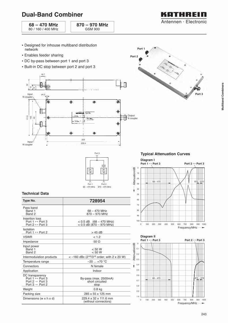
Diagram IPort 1 ÷ Port 3 Port 2 ÷ Port 3
Diagram IIPort 1 ÷ Port 3 Port 2 ÷ Port 3
Typical Attenuation Curves
Dual-Band Combiner
Port 1
Port 2
Port 3
• Designed for inhouse multiband distributionnetwork
• Enables feeder sharing
• DC by-pass between port 1 and port 3
• Built-in DC stop between port 2 and port 3
Type No. 728954
Pass bandBand 1 68 – 470 MHzBand 2 870 – 970 MHz
Insertion lossPort 1 ÷ Port 3 < 0.5 dB (68 – 470 MHz)Port 2 ÷ Port 3 < 0.5 dB (870 – 970 MHz)
IsolationPort 1 ÷ Port 2 > 45 dB
VSWR < 1.2
Impedance 50 Ω
Input powerBand 1 < 50 WBand 2 < 50 W
Intermodulation products < –160 dBc (2nd/3rd order; with 2 x 20 W)
Temperature range –20 ... +70 °C
Connectors N female
Application Indoor
DC transparencyPort 1 ÷ Port 3 By-pass (max. 2500mA)Port 2 ’ Port 3 short circuitedPort 3 ’ Port 2 stop
Weight 0.8 kg
Packing size 285 x 55 x 125 mm
Dimensions (w x h x d) 229.4 x 32 x 111.6 mm(without connectors)
Technical Data
Port 3
Port 2Port 1
68 – 470 MHz80 / 160 / 400 MHz
870 – 970 MHzGSM 900
68 – 470 MHz 870 – 970 MHz
OutputN coupler
InputN coupler
InputN coupler
15
12
32
18.7
ø4.3
40
111
.6
10
5
223
229.4
244
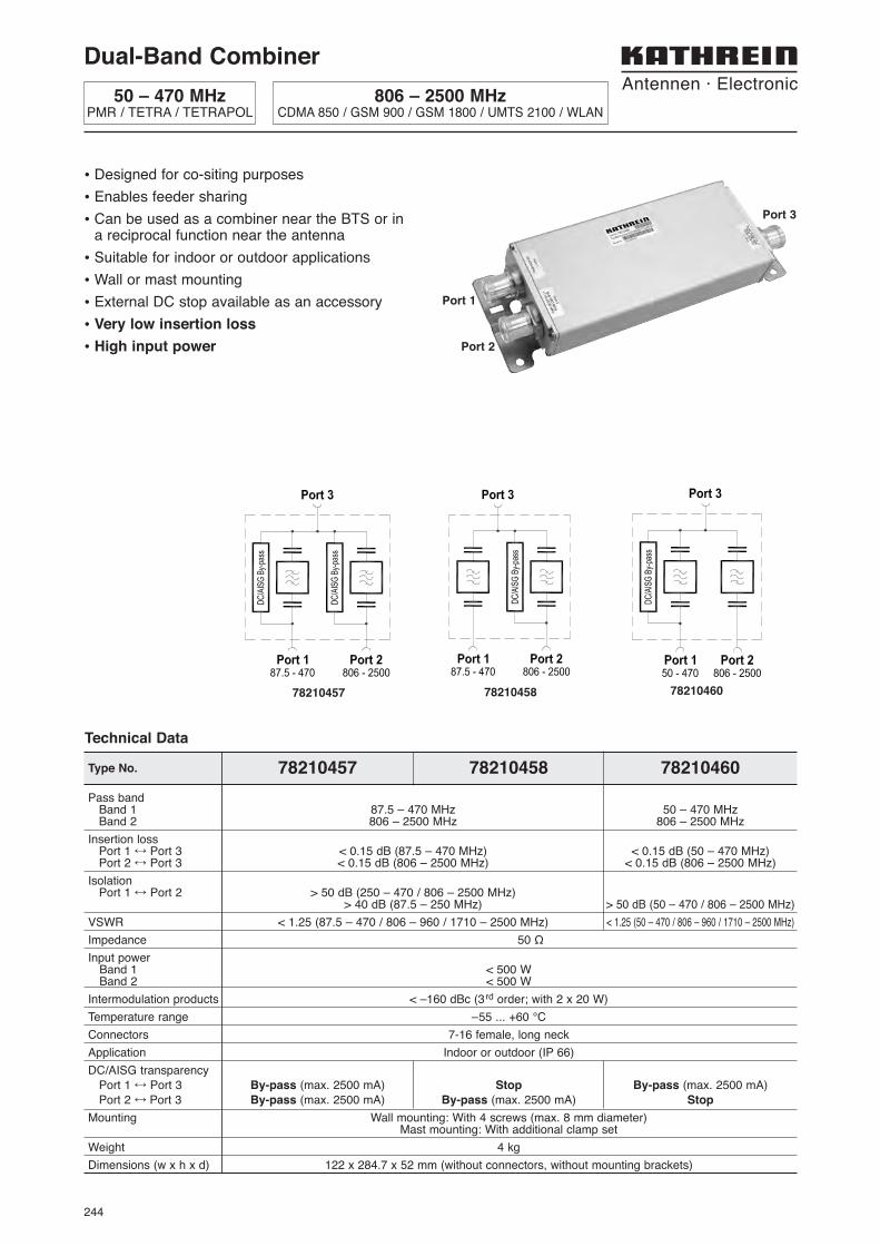
Dual-Band Combiner
50 – 470 MHzPMR / TETRA / TETRAPOL
806 – 2500 MHzCDMA 850 / GSM 900 / GSM 1800 / UMTS 2100 / WLAN
• Designed for co-siting purposes
• Enables feeder sharing
• Can be used as a combiner near the BTS or ina reciprocal function near the antenna
• Suitable for indoor or outdoor applications
• Wall or mast mounting
• External DC stop available as an accessory
• Very low insertion loss
• High input power
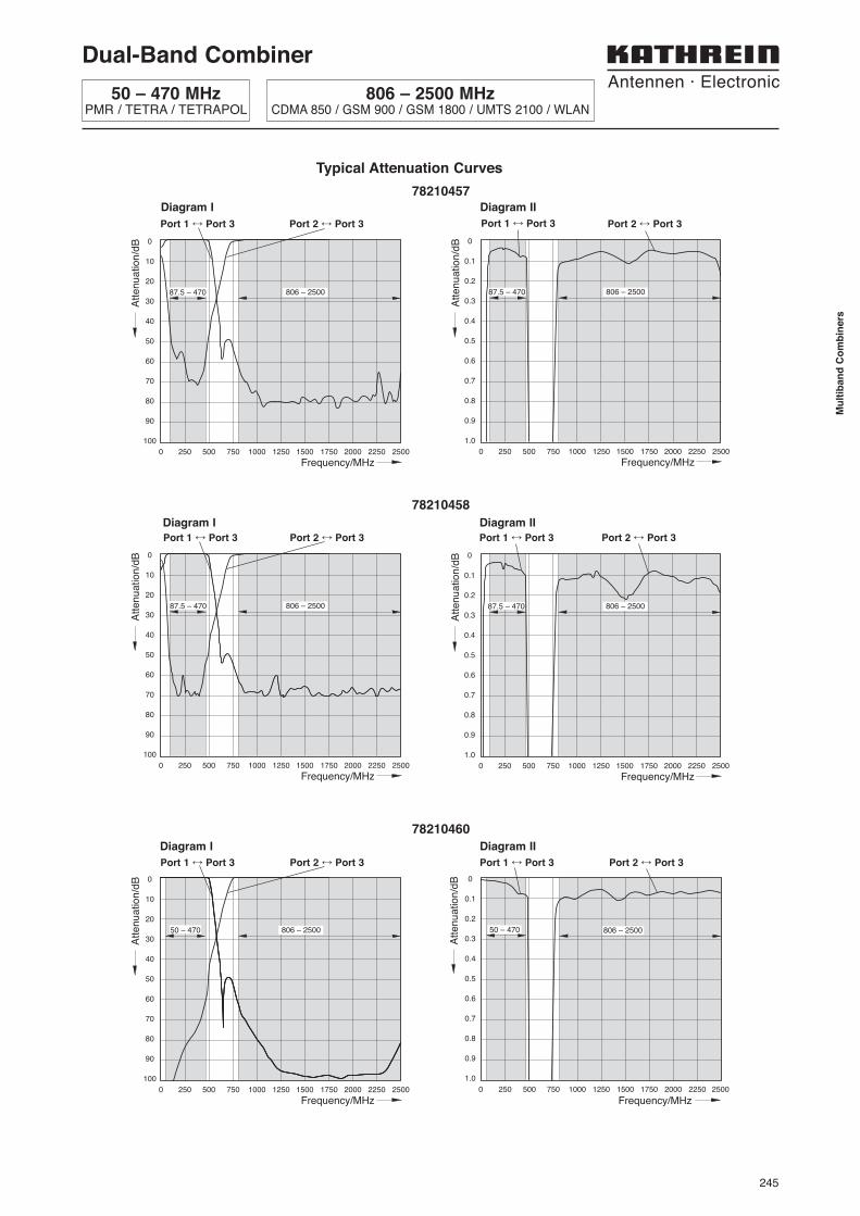
Type No. 78210457 78210458 78210460
Pass bandBand 1 87.5 – 470 MHz 50 – 470 MHzBand 2 806 – 2500 MHz 806 – 2500 MHz
Insertion lossPort 1 ÷ Port 3 < 0.15 dB (87.5 – 470 MHz) < 0.15 dB (50 – 470 MHz)Port 2 ÷ Port 3 < 0.15 dB (806 – 2500 MHz) < 0.15 dB (806 – 2500 MHz)
IsolationPort 1 ÷ Port 2 > 50 dB (250 – 470 / 806 – 2500 MHz)
> 40 dB (87.5 – 250 MHz) > 50 dB (50 – 470 / 806 – 2500 MHz)
VSWR < 1.25 (87.5 – 470 / 806 – 960 / 1710 – 2500 MHz) < 1.25 (50 – 470 / 806 – 960 / 1710 – 2500 MHz)
Impedance 50 Ω
Input powerBand 1 < 500 WBand 2 < 500 W
Intermodulation products < –160 dBc (3rd order; with 2 x 20 W)
Temperature range –55 ... +60 °C
Connectors 7-16 female, long neck
Application Indoor or outdoor (IP 66)
DC/AISG transparency
Port 1 ÷ Port 3 By-pass (max. 2500 mA) Stop By-pass (max. 2500 mA)
Port 2 ÷ Port 3 By-pass (max. 2500 mA) By-pass (max. 2500 mA) Stop
Mounting Wall mounting: With 4 screws (max. 8 mm diameter)Mast mounting: With additional clamp set
Weight 4 kg
Dimensions (w x h x d) 122 x 284.7 x 52 mm (without connectors, without mounting brackets)
Technical Data
Port 3
Port 1
Port 2
78210457 78210458 78210460
245
Mu
ltib
an
d C
om
bin
ers
0
0.1
0.2
0.3
0.4
0.5
0.6
0.7
0.8
0.9
1.0
Att
en
ua
tio
n/d
BFrequency/MHz
0 250 500 750 1000 1250 1500 1750 2000 2250 2500
806 – 250087.5 – 470
Typical Attenuation Curves
Diagram I Diagram II
Port 1 ÷ Port 3 Port 2 ÷ Port 3Port 1 ÷ Port 3 Port 2 ÷ Port 3
0
10
20
30
40
50
60
70
80
90
100
Att
en
ua
tio
n/d
B
Frequency/MHz0 250 500 750 1000 1250 1500 1750 2000 2250 2500
806 – 250087.5 – 470
78210457
0
0.1
0.2
0.3
0.4
0.5
0.6
0.7
0.8
0.9
1.0
Att
en
ua
tio
n/d
B
Frequency/MHz0 250 500 750 1000 1250 1500 1750 2000 2250 2500
806 – 250087.5 – 470
Diagram I Diagram II
Port 1 ÷ Port 3 Port 2 ÷ Port 3Port 1 ÷ Port 3 Port 2 ÷ Port 3
0
10
20
30
40
50
60
70
80
90
100
Att
en
ua
tio
n/d
B
Frequency/MHz0 250 500 750 1000 1250 1500 1750 2000 2250 2500
806 – 250087.5 – 470
78210458
0
0.1
0.2
0.3
0.4
0.5
0.6
0.7
0.8
0.9
1.0
0 250 500 750 1000 1250 1500 1750 2000 2250 2500
Att
en
ua
tio
n/d
B
Frequency/MHz
806 – 2500 50 – 470
Diagram I Diagram II
Port 1 ÷ Port 3 Port 2 ÷ Port 3Port 1 ÷ Port 3 Port 2 ÷ Port 3
0
10
20
30
40
50
60
70
80
90
100
Att
en
ua
tio
n/d
B
Frequency/MHz0 250 500 750 1000 1250 1500 1750 2000 2250 2500
50 – 470 806 – 2500
78210460
Dual-Band Combiner
50 – 470 MHzPMR / TETRA / TETRAPOL
806 – 2500 MHzCDMA 850 / GSM 900 / GSM 1800 / UMTS 2100 / WLAN
246
0
10
20
30
40
50
60
70
80
90
100
0 200 400 600 800 1000 1200 1400 1600 1800 2000
Attenuation/d
B
Frequency/MHz
50 – 1000 1600 – 2000
0
0.1
0.2
0.3
0.4
0.5
0.6
0.7
0.8
0.9
1.0
0 200 400 600 800 1000 1200 1400 1600 1800 2000
Attenuation/d
B
Frequency/MHz
1600 – 200050 – 1000
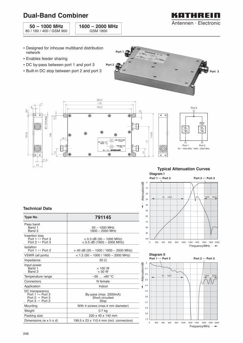
Diagram I
Port 1 ÷ Port 3 Port 2 ÷ Port 3
Diagram IIPort 1 ÷ Port 3 Port 2 ÷ Port 3
Pass bandBand 1 50 – 1000 MHzBand 2 1600 – 2000 MHz
Insertion lossPort 1 ÷ Port 3 < 0.3 dB (50 – 1000 MHz)Port 2 ÷ Port 3 < 0.5 dB (1600 – 2000 MHz)
IsolationPort 1 ÷ Port 2 > 40 dB (50 – 1000 / 1600 – 2000 MHz)
VSWR (all ports) < 1.2 (50 – 1000 / 1600 – 2000 MHz)
Impedance 50 Ω
Input powerBand 1 < 100 WBand 2 < 50 W
Temperature range –30 … +60 °C
Connectors N female
Application Indoor
DC transparencyPort 1 ÷ Port 3 By-pass (max. 2500mA)Port 2 ’ Port 3 Short circuitedPort 3 ’ Port 2 Stop
Mounting With 4 screws (max.4 mm diameter)
Weight 0.7 kg
Packing size 220 x 40 x 140 mm
Dimensions (w x h x d) 199.5 x 23 x 110.4 mm (incl. connectors)
Type No. 791145
Technical Data
• Designed for inhouse multiband distributionnetwork
• Enables feeder sharing
• DC by-pass between port 1 and port 3
• Built-in DC stop between port 2 and port 3
Port 1
Port 2
Port 3
Dual-Band Combiner
50 – 1000 MHz80 / 160 / 400 / GSM 900
1600 – 2000 MHzGSM 1800
deep
Port 3
Port 2Port 1
50 – 1000 MHz 1600 – 2000 MHz
Typical Attenuation Curves
247
Mu
ltib
an
d C
om
bin
ers
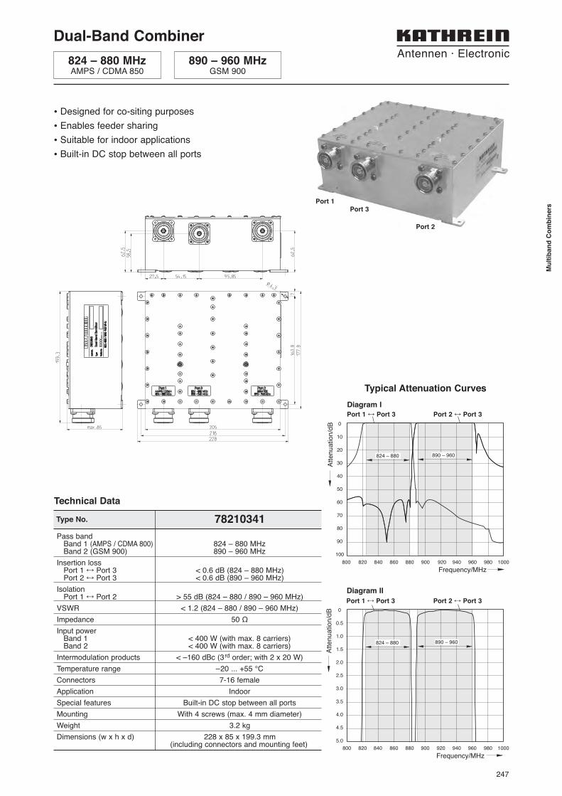
Dual-Band Combiner
824 – 880 MHzAMPS / CDMA 850
890 – 960 MHzGSM 900
• Designed for co-siting purposes
• Enables feeder sharing
• Suitable for indoor applications
• Built-in DC stop between all ports
Port 1Port 3
Port 2
0
0.5
1.0
1.5
2.0
2.5
3.0
3.5
4.0
4.5
5.0
800 820 840 860 880 900 920 940 960 980 1000
Att
en
ua
tio
n/d
B
Frequency/MHz
824 – 880 890 – 960
0
10
20
30
40
50
60
70
80
90
100
Att
en
ua
tio
n/d
B
Frequency/MHz
800 820 840 860 880 900 920 940 960 980 1000
824 – 880 890 – 960
Typical Attenuation Curves
Port 1 ÷ Port 3 Port 2 ÷ Port 3
Diagram I
Diagram II
Port 1 ÷ Port 3 Port 2 ÷ Port 3
Type No. 78210341
Pass bandBand 1 (AMPS / CDMA 800) 824 – 880 MHzBand 2 (GSM 900) 890 – 960 MHz
Insertion lossPort 1 ÷ Port 3 < 0.6 dB (824 – 880 MHz)Port 2 ÷ Port 3 < 0.6 dB (890 – 960 MHz)
IsolationPort 1 ÷ Port 2 > 55 dB (824 – 880 / 890 – 960 MHz)
VSWR < 1.2 (824 – 880 / 890 – 960 MHz)
Impedance 50 Ω
Input powerBand 1 < 400 W (with max. 8 carriers)Band 2 < 400 W (with max. 8 carriers)
Intermodulation products < –160 dBc (3rd order; with 2 x 20 W)
Temperature range –20 ... +55 °C
Connectors 7-16 female
Application Indoor
Special features Built-in DC stop between all ports
Mounting With 4 screws (max. 4 mm diameter)
Weight 3.2 kg
Dimensions (w x h x d) 228 x 85 x 199.3 mm(including connectors and mounting feet)
Technical Data
248
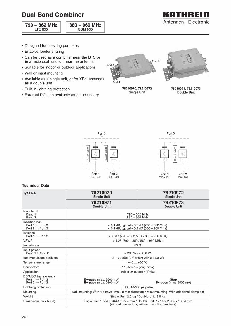
Dual-Band Combiner
790 – 862 MHzLTE 800
880 – 960 MHzGSM 900
• Designed for co-siting purposes
• Enables feeder sharing
• Can be used as a combiner near the BTS or in a reciprocal function near the antenna
• Suitable for indoor or outdoor applications
• Wall or mast mounting
• Available as a single unit, or for XPol antennasas a double unit
• Built-in lightning protection
• External DC stop available as an accessory
Pass bandBand 1 790 – 862 MHzBand 2 880 – 960 MHz
Insertion lossPort 1 ÷ Port 3 < 0.4 dB, typically 0.2 dB (790 – 862 MHz)Port 2 ÷ Port 3 < 0.4 dB, typically 0.2 dB (880 – 960 MHz)
IsolationPort 1 ÷ Port 2 > 50 dB (790 – 862 MHz / 880 – 960 MHz)
VSWR < 1.25 (790 – 862 / 880 – 960 MHz)
Impedance 50 Ω
Input powerBand 1 / Band 2 < 200 W / < 200 W
Intermodulation products < –160 dBc (3rd order; with 2 x 20 W)
Temperature range –40 ... +60 °C
Connectors 7-16 female (long neck)
Application Indoor or outdoor (IP 66)
DC/AISG transparencyPort 1 ÷ Port 3 By-pass (max. 2500 mA) StopPort 2 ÷ Port 3 By-pass (max. 2500 mA) By-pass (max. 2500 mA)
Lightning protection 3 kA, 10/350 μs pulse
Mounting Wall mounting: With 4 screws (max. 8 mm diameter) / Mast mounting: With additional clamp set
Weight Single Unit: 2.9 kg / Double Unit: 5.8 kg
Dimensions (w x h x d) Single Unit: 177.4 x 209.4 x 52.4 mm / Double Unit: 177.4 x 209.4 x 108.4 mm(without connectors, without mounting brackets)
Type No. 78210970 78210972Single Unit Single Unit
78210971 78210973Double Unit Double Unit
Technical Data
78210970, 78210972Single Unit
78210971, 78210973Double Unit
Port 1
Port 2
Port 3
249
Mu
ltib
an
d C
om
bin
ers
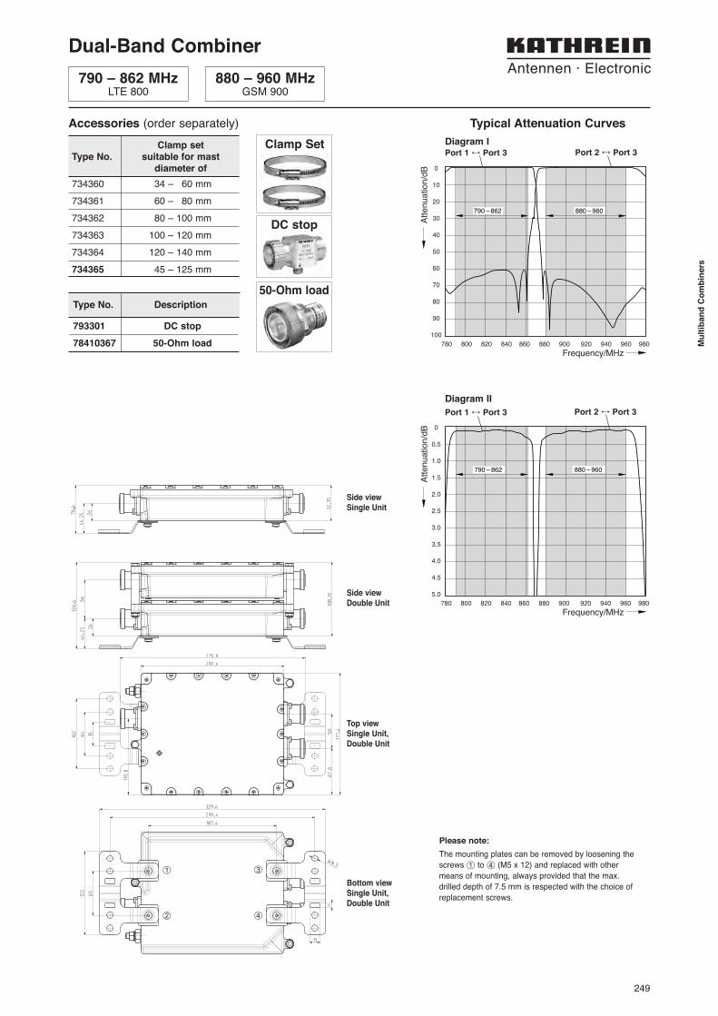
The mounting plates can be removed by loosening the
screws ¿ to √ (M5 x 12) and replaced with other
means of mounting, always provided that the max.
drilled depth of 7.5 mm is respected with the choice of
replacement screws.
Please note:
Dual-Band Combiner
790 – 862 MHzLTE 800
880 – 960 MHzGSM 900
Accessories (order separately)
734360 34 – 60 mm
734361 60 – 80 mm
734362 80 – 100 mm
734363 100 – 120 mm
734364 120 – 140 mm
734365 45 – 125 mm
Clamp setType No. suitable for mast
diameter of
Clamp Set
DC stop
Type No. Description
793301 DC stop
78410367 50-Ohm load
50-Ohm load
Port 2 ÷ Port 3
Typical Attenuation Curves
790 – 862 880 – 960
790 – 862 880 – 960
Diagram II
Diagram IPort 1 ÷ Port 3 Port 2 ÷ Port 3
Port 1 ÷ Port 3
Side viewSingle Unit
Top viewSingle Unit,Double Unit
Side viewDouble Unit
Bottom viewSingle Unit,Double Unit
¿
¡
¬
√

250
Dual-Band Combiner
470 – 960 MHzLTE 800 / CDMA 850 / GSM 900
1710 – 2700 MHzGSM 1800 / UMTS 2100 / WiMAX / LTE 2600
• Designed for co-siting purposes
• Enables feeder sharing
• Can be used as a combiner near the BTS or in a reciprocal function near the antenna
• Suitable for indoor or outdoor applications
• Wall or mast mounting
• Available as a single unit, or for XPol anten-nas as a double unit
• Built-in lightning protection
• External DC stop available as an accessory
• Extremely small dimensions and low weight
• Very low insertion loss
• High input power
78210661, 78210663, 78210665Double Unit
78210660, 78210662, 78210664Single Unit
Port 1
Port 2
Port 3
Pass bandBand 1 470 – 960 MHzBand 2 1710 – 2700 MHz
Insertion lossPort 1 ÷ Port 3 < 0.15 dB (470 – 960 MHz), typically 0.1 dB (470 – 960 MHz)Port 2 ÷ Port 3 < 0.2 dB (1710 – 2700 MHz), typically 0.1 dB (1710 – 2700 MHz)
IsolationPort 1 ÷ Port 2 > 55 dB (470 – 960 MHz) / > 65 dB (1710 – 2700 MHz)
VSWR < 1.2 (470 – 960 / 1710 – 2700 MHz)
Impedance 50 Ohm
Input powerBand 1 / Band 2 < 650 W / < 350 W
Intermodulation products < –160 dBc (3rd order with 2 x 20 W)
Temperature range –55 ... +60 °C
Connectors 7-16 female (long neck)
Application Indoor or outdoor (IP 66)
DC/AISG transparencyPort 1 ÷ Port 3 By-pass (max. 2500 mA) Stop By-pass (max. 2500 mA)Port 2 ÷ Port 3 By-pass (max. 2500 mA) By-pass (max. 2500 mA) Stop
Lightning protection 3 kA, 10/350 μs pulse
Mounting Wall mounting: With 4 screws (max. 8 mm diameter) / Mast mounting: With additional clamp set
Weight Single Unit: 1.2 kg / Double Unit: 2.4 kg
Packing size Single Unit: 285 x 157 x 93 mm / Double Unit: 285 x 157 x 148 mm
Dimensions (w x h x d) Single Unit: 126 x 145 x 38 mm / Double Unit: 126 x 145 x 93 mm(without connectors, without mounting brackets)
Type No. 78210660 78210662 78210664Single Unit Single Unit Single Unit
78210661 78210663 78210665Double Unit Double Unit Double Unit
Technical Data

251
Mu
ltib
an
d C
om
bin
ers
�������� �������� � ���������������������������
Side viewSingle Unit
Top viewSingle Unit,Double Unit
Side viewDouble Unit
Dual-Band Combiner
470 – 960 MHzLTE 800 / CDMA 850 / GSM 900
1710 – 2700 MHzGSM 1800 / UMTS 2100 / WiMAX / LTE 2600
Accessories (order separately)
734360 34 – 60 mm
734361 60 – 80 mm
734362 80 – 100 mm
734363 100 – 120 mm
734364 120 – 140 mm
734365 45 – 125 mm
Clamp setType No. suitable for mast
diameter of
Clamp Set
DC stop
Type No. Description
78210850 DC stop
78410367 50-Ohm load
50-Ohm load
0
-10
-20
-30
-40
-50
-60
-70
-80
-90
-100
Attenuation/d
B
Frequency/MHz
1710 – 2700
0 300 600 900 1200 1500 1800 2100 2400 2700 3000
470 – 960
0
-0.1
-0.2
-0.3
-0.4
-0.5
-0.6
-0.7
-0.8
-0.9
-1.0 0 300 600 900 1200 1500 1800 2100 2400 2700 3000
Atte
nuat
ion/
dB
Frequency/MHz
1710 – 2700470 – 960
Typical Attenuation Curves
Diagram II
Port 1 ÷ Port 3 Port 2 ÷ Port 3
Diagram IPort 1 ÷ Port 3 Port 2 ÷ Port 3
252
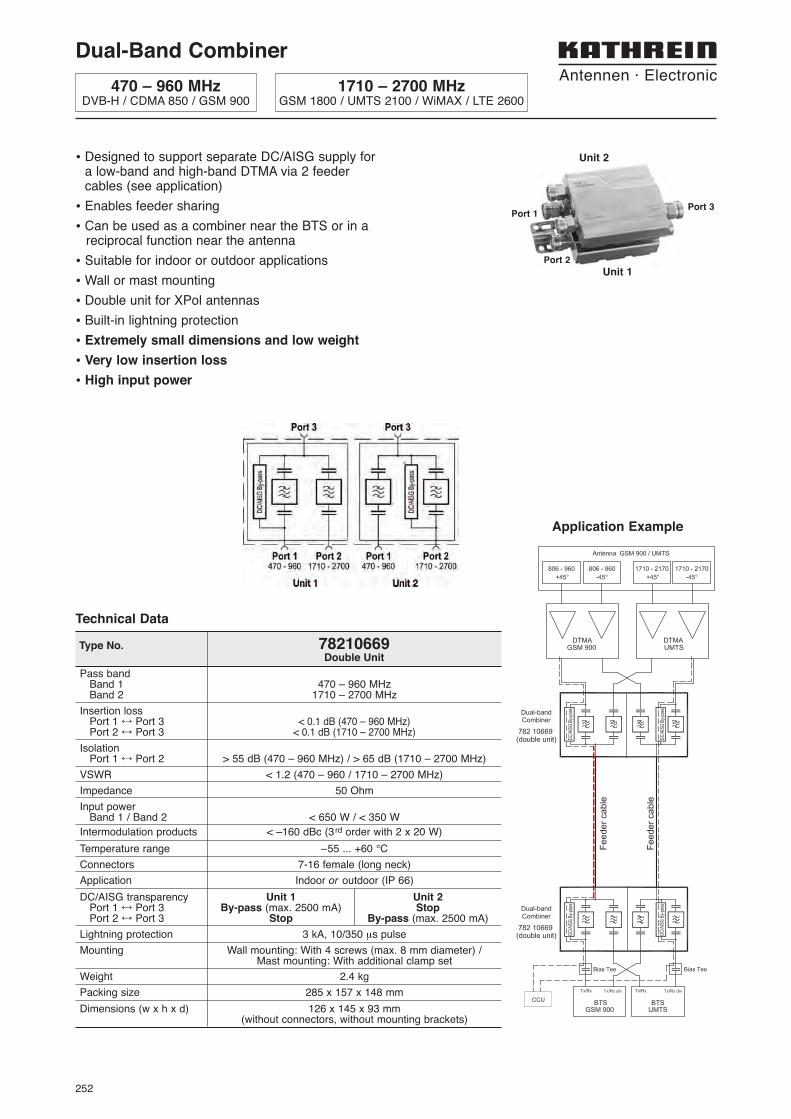
Dual-Band Combiner
470 – 960 MHzDVB-H / CDMA 850 / GSM 900
1710 – 2700 MHzGSM 1800 / UMTS 2100 / WiMAX / LTE 2600
• Designed to support separate DC/AISG supply for a low-band and high-band DTMA via 2 feeder cables (see application)
• Enables feeder sharing
• Can be used as a combiner near the BTS or in a reciprocal function near the antenna
• Suitable for indoor or outdoor applications
• Wall or mast mounting
• Double unit for XPol antennas
• Built-in lightning protection
• Extremely small dimensions and low weight
• Very low insertion loss
• High input power
Pass bandBand 1 470 – 960 MHzBand 2 1710 – 2700 MHz
Insertion lossPort 1 ÷ Port 3 < 0.1 dB (470 – 960 MHz)Port 2 ÷ Port 3 < 0.1 dB (1710 – 2700 MHz)
IsolationPort 1 ÷ Port 2 > 55 dB (470 – 960 MHz) / > 65 dB (1710 – 2700 MHz)
VSWR < 1.2 (470 – 960 / 1710 – 2700 MHz)
Impedance 50 Ohm
Input powerBand 1 / Band 2 < 650 W / < 350 W
Intermodulation products < –160 dBc (3rd order with 2 x 20 W)
Temperature range –55 ... +60 °C
Connectors 7-16 female (long neck)
Application Indoor or outdoor (IP 66)
DC/AISG transparency Unit 1 Unit 2Port 1 ÷ Port 3 By-pass (max. 2500 mA) StopPort 2 ÷ Port 3 Stop By-pass (max. 2500 mA)
Lightning protection 3 kA, 10/350 μs pulse
Mounting Wall mounting: With 4 screws (max. 8 mm diameter) / Mast mounting: With additional clamp set
Weight 2.4 kg
Packing size 285 x 157 x 148 mm
Dimensions (w x h x d) 126 x 145 x 93 mm(without connectors, without mounting brackets)
Type No. 78210669Double Unit
Technical Data
Application Example
Port 1
Port 2
Port 3
Unit 2
Unit 1

253
Mu
ltib
an
d C
om
bin
ers
�������� �������� � ���������������������������
Top view
Side view
470 – 960 MHzDVB-H / CDMA 850 / GSM 900
1710 – 2700 MHzGSM 1800 / UMTS 2100 / WiMAX / LTE 2600
0
-10
-20
-30
-40
-50
-60
-70
-80
-90
-100
Atte
nuat
ion/
dB
Frequency/MHz
1710 – 2700
0 300 600 900 1200 1500 1800 2100 2400 2700 3000
470 – 960
0
-0.1
-0.2
-0.3
-0.4
-0.5
-0.6
-0.7
-0.8
-0.9
-1.0 0 300 600 900 1200 1500 1800 2100 2400 2700 3000
Atte
nuat
ion/
dB
Frequency/MHz
1710 – 2700470 – 960
Typical Attenuation Curves
Diagram II
Port 1 ÷ Port 3 Port 2 ÷ Port 3
Diagram IPort 1 ÷ Port 3 Port 2 ÷ Port 3
Accessories (order separately)
734360 34 – 60 mm
734361 60 – 80 mm
734362 80 – 100 mm
734363 100 – 120 mm
734364 120 – 140 mm
734365 45 – 125 mm
Clamp setType No. suitable for mast
diameter of
Clamp Set
DC stop
Type No. Description
78210850 DC stop
78410367 50-Ohm load
50-Ohm load
Dual-Band Combiner

254
Dual-Band Combiner
380 – 960 MHzTETRA / LTE800 / CDMA850 / GSM900
1710 – 2700 MHzGSM1800 / UMTS2100 / WiMAX / LTE2600
• Designed for co-siting purposes
• Enables feeder sharing
• Can be used as a combiner near the BTS or in a reciprocal function near the antenna
• Suitable for indoor or outdoor applications
• Wall or mast mounting
• Available as a single unit, or for XPol anten-nas as a double unit
• Built-in lightning protection
• External DC stop available as an accessory
• Extremely low insertion loss
• High input power
78210680, 78210682Single Unit
Port 1
Port 2
Pass bandBand 1 380 – 960 MHzBand 2 1710 – 2700 MHz
Insertion lossPort 1 ÷ Port 3 < 0.1 dB (380 – 960 MHz)Port 2 ÷ Port 3 < 0.1 dB (1710 – 2700 MHz)
IsolationPort 1 ÷ Port 2 > 55 dB (380 – 550 MHz) / > 65 dB (550 – 960 MHz) / > 65 dB (1710 – 2700 MHz)
VSWR < 1.2 (380 – 960 / 1710 – 2700 MHz)
Impedance 50 Ω
Input powerBand 1 / Band 2 < 700 W / < 700 W
Intermodulation products < –160 dBc (3rd order; with 2 x 20 W)
Temperature range –55 ... +60 °C
Connectors 7-16 female (long neck)
Application Indoor or outdoor (IP 66)
DC/AISG transparencyPort 1 ÷ Port 3 By-pass (max. 2500 mA) StopPort 2 ÷ Port 3 By-pass (max. 2500 mA) By-pass (max. 2500 mA)
Lightning protection 3 kA, 10/350 μs pulse
Mounting Wall mounting: With 4 screws (max. 8 mm diameter) / Mast mounting: With additional clamp set
Weight Single Unit: 2.2 kg / Double Unit: 4.3 kg
Packing size Single Unit: 365 x 207 x 150 mm / Double Unit: 365 x 207 x 214 mm
Dimensions (w x h x d) Single Unit: 117 x 209.5 x 48.8 mm / Double Unit: 117 x 209.5 x 99.5 mm(without connectors, without mounting brackets)
Type No. 78210680 78210682Single Unit Single Unit
78210681 78210683Double Unit Double Unit
Technical Data380 – 960 1710 – 2700 380 – 960 1710 – 2700
78210681, 78210683Double Unit
Port 3
255
Mu
ltib
an
d C
om
bin
ers
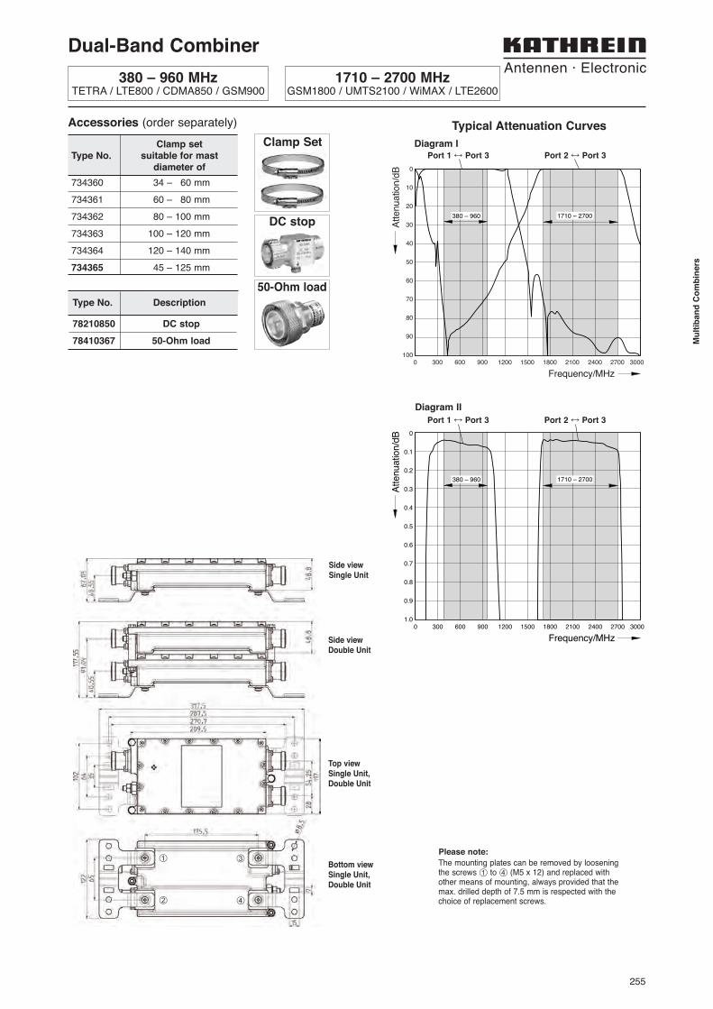
Side viewSingle Unit
Side viewDouble Unit
Top viewSingle Unit,Double Unit
Bottom viewSingle Unit,Double Unit
Accessories (order separately)
734360 34 – 60 mm
734361 60 – 80 mm
734362 80 – 100 mm
734363 100 – 120 mm
734364 120 – 140 mm
734365 45 – 125 mm
Clamp setType No. suitable for mast
diameter of
Clamp Set
Type No. Description
78210850 DC stop
78410367 50-Ohm load
50-Ohm load
0
0.1
0.2
0.3
0.4
0.5
0.6
0.7
0.8
0.9
1.0 0 300 600 900 1200 1500 1800 2100 2400 2700 3000
Atte
nuat
ion/d
B
Frequency/MHz
1710 – 2700380 – 960
Typical Attenuation Curves
Diagram II
Port 1 ÷ Port 3 Port 2 ÷ Port 3
Diagram IPort 1 ÷ Port 3 Port 2 ÷ Port 3
1710 – 2700380 – 960
¿
¡
¬
√
Dual-Band Combiner
The mounting plates can be removed by looseningthe screws ¿ to √ (M5 x 12) and replaced withother means of mounting, always provided that themax. drilled depth of 7.5 mm is respected with thechoice of replacement screws.
Please note:
DC stop
380 – 960 MHzTETRA / LTE800 / CDMA850 / GSM900
1710 – 2700 MHzGSM1800 / UMTS2100 / WiMAX / LTE2600

256
• Designed for co-siting purposes
• Enables feeder sharing
• Can be used as a combiner near the BTSor in a reciprocal function near the antenna
• Suitable for indoor or outdoor applications
• Wall or mast mounting
• Available as a single unit, or for XPol an-tennas as a double unit
• Built-in lightning protection
• External DC Stop available as an accessory
Port 1
Port 2
Port 3
78210278, 78210305Single Unit
78210279, 78210306Double Unit
Dual-Band Combiner
790 – 1880 MHzLTE 800 / CDMA 850 / GSM 900 / GSM 1800
1920 – 2170 MHzUMTS 2100
Pass bandBand 1 790 – 1880 MHz
Band 2 1920 – 2170 MHz
Insertion lossPort 1 ÷ Port 3 < 0.1 dB, typically 0.05 dB (790 – 960 MHz) / < 0.4 dB, typically 0.2 dB (1710 – 1880 MHz)
Port 2 ÷ Port 3 < 0.4 dB, typically 0.2 dB (1920 – 2170 MHz)
IsolationPort 1 ÷ Port 2 > 55 dB (790 – 960 MHz) / > 50 dB (1710 – 1880 MHz) / > 50 dB (1920 – 2170 MHz)
VSWR < 1.2 (790 – 960 MHz) / < 1.25 (1710 – 1880 MHz) / < 1.2 (1920 – 2170 MHz)
Impedance 50 Ω
Input powerBand 1 / Band 2 < 500 W / < 500 W
Intermodulation products < –160 dBc (2nd/3rd order; with 2 x 20 W)
Temperature range –55 ... +60 °C
Connectors 7-16 female (long neck)
Application Indoor or outdoor (IP 66)
DC/AISG transparencyPort 1 ÷ Port 3 By-pass (max. 2500 mA) Stop
Port 2 ÷ Port 3 By-pass (max. 2500 mA) By-pass (max. 2500 mA)
Lightning protection 3 kA, 10/350 μs pulse
Mounting Wall mounting: With 4 screws (max. 8 mm diameter) / Mast mounting: With additional clamp set
Weight Single Unit: 3.4 kg / Double Unit: 6.6 kg
Packing size Single Unit: 207 x 437 x 154 mm / Double Unit: 207 x 437 x 214 mm
Dimensions (w x h x d) Single Unit: 122 x 269.9 x 43 mm / Double Unit:122 x 269.9 x 98.5 mm
(without connectors, without mounting brackets)
Type No. 78210278 78210305Single Unit Single Unit
78210279 78210306Double Unit Double Unit
Technical Data
257
Mu
ltib
an
d C
om
bin
ers
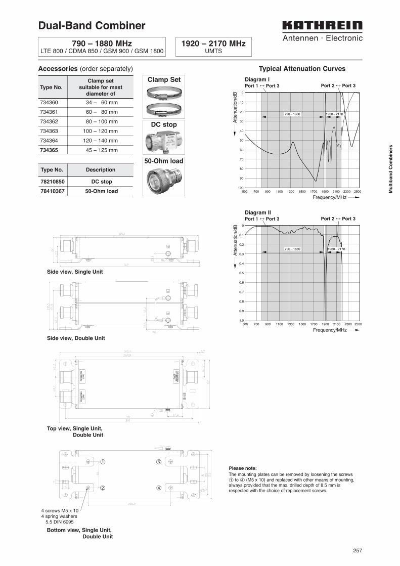
Side view, Double Unit
Top view, Single Unit, Double Unit
Side view, Single Unit
Bottom view, Single Unit, Double Unit
¿
¡
¬
√
4 screws M5 x 104 spring washers
5.5 DIN 6095
The mounting plates can be removed by loosening the screws
¿ to √ (M5 x 10) and replaced with other means of mounting,always provided that the max. drilled depth of 8.5 mm is respected with the choice of replacement screws.
Please note:
790 – 1880 1920 – 2170
790 – 1880 1920 – 2170
Accessories (order separately)
734360 34 – 60 mm
734361 60 – 80 mm
734362 80 – 100 mm
734363 100 – 120 mm
734364 120 – 140 mm
734365 45 – 125 mm
Clamp setType No. suitable for mast
diameter of
Clamp Set
DC stop
Type No. Description
78210850 DC stop
78410367 50-Ohm load
50-Ohm load
Dual-Band Combiner
790 – 1880 MHzLTE 800 / CDMA 850 / GSM 900 / GSM 1800
1920 – 2170 MHzUMTS
Typical Attenuation Curves
Diagram IPort 1 ÷ Port 3 Port 2 ÷ Port 3
Diagram IIPort 1 ÷ Port 3 Port 2 ÷ Port 3

258
Port 1
Port 2
Port 3
• Designed for co-siting purposes
• Enables feeder sharing
• Can be used as a combiner near the BTSor in a reciprocal function near the antenna
• Suitable for indoor or outdoor applications
• Wall or mast mounting
• Available as a single unit, or for XPol anten-nas as a double unit
• Built-in lightning protection
• External DC Stop available as an accessory
Type No. 78210620 78210622 78210624Single Unit Single Unit Single Unit
78210621 78210623 78210625Double Unit Double Unit Double Unit
Pass bandBand 1 (GSM 1800) 1710 – 1880 MHzBand 2 (UMTS) 1920 – 2170 MHz
Insertion lossPort 1 ÷ Port 3 < 0.3 dB (1710 – 1880 MHz)Port 2 ÷ Port 3 < 0.3 dB (1920 – 2170 MHz)
IsolationPort 1 ÷ Port 2 > 50 dB (1710 – 1880 / 1920 – 2170 MHz)
VSWR < 1.25 (1710 – 1880 / 1920 – 2170 MHz)
Impedance 50 Ω
Input powerBand 1 / Band 2 < 300 W / < 300 W
Intermodulation products < –160 dBc (3rd order; with 2 x 20 W)
Temperature range –40 ... +60 °C
Connectors 7-16 female (long neck)
Application Indoor or outdoor (IP 66)
DC/AISG transparencyPort 1 ÷ Port 3 By-pass (max. 2500 mA) Stop By-pass (max. 2500 mA)Port 2 ÷ Port 3 By-pass (max. 2500 mA) By-pass (max. 2500 mA) Stop
Lightning protection 3 kA, 10/350 μs pulse
Mounting Wall mounting: With 4 screws (max. 8 mm diameter) / Mast mounting: With additional clamp set
Weight Single Unit: 2.9 kg / Double Unit: 5.7 kg
Packing size Single Unit: 392 x 272 x 139 mm / Double Unit: 392 x 272 x 189 mm
Dimensions (w x h x d) Single Unit: 199 x 199 x 48 mm / Double Unit: 199 x 199 x 104 mm(without connectors, without mounting brackets)
Technical Data
78210620, 78210622, 78210624Single Unit
78210621, 78210623, 78210625Double Unit
Dual-Band Combiner
1710 – 1880 MHzGSM 1800
1920 – 2170 MHzUMTS 2100

259
Mu
ltib
an
d C
om
bin
ers
Dual-Band Combiner
1710 – 1880 MHzGSM 1800
1920 – 2170 MHzUMTS 2100
0
-10
-20
-30
-40
-50
-60
-70
-80
-90
-1001400 1500 1600 1700 1800 1900 2000 2100 2200 2300 2400
Atte
nuat
ion/d
B
Frequency/MHz
1710 – 1880 1920 – 2170
1710 – 1880 1920 – 2170
Typical Attenuation Curves
Port 1 ÷ Port 3 Port 2 ÷ Port 3
Diagram I
Diagram II
Port 1 ÷ Port 3 Port 2 ÷ Port 3
The mounting plates can be removed by loosening thescrews ¿ to √ (M5 x 12) and replaced with othermeans of mounting, always provided that the max.drilled depth of 7.5 mm is respected with the choice ofreplacement screws.
Please note:
Accessories (order separately)
734360 34 – 60 mm
734361 60 – 80 mm
734362 80 – 100 mm
734363 100 – 120 mm
734364 120 – 140 mm
734365 45 – 125 mm
Clamp setType No. suitable for mast
diameter of
Clamp Set
DC stop
Type No. Description
793301 DC stop
78410367 50-Ohm load
50-Ohm load
¿
¡
¬
√
Side viewSingle Unit
Top viewSingle Unit,Double Unit
Side viewDouble Unit
Bottom viewSingle Unit,Double Unit
260
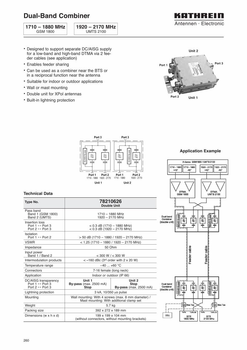
Dual-Band Combiner
1710 – 1880 MHzGSM 1800
1920 – 2170 MHzUMTS 2100
Pass bandBand 1 (GSM 1800) 1710 – 1880 MHzBand 2 (UMTS) 1920 – 2170 MHz
Insertion lossPort 1 ÷ Port 3 < 0.3 dB (1710 – 1880 MHz)Port 2 ÷ Port 3 < 0.3 dB (1920 – 2170 MHz)
IsolationPort 1 ÷ Port 2 > 50 dB (1710 – 1880 / 1920 – 2170 MHz)
VSWR < 1.25 (1710 – 1880 / 1920 – 2170 MHz)
Impedance 50 Ohm
Input powerBand 1 / Band 2 < 300 W / < 300 W
Intermodulation products < –160 dBc (3rd order with 2 x 20 W)
Temperature range –40 ... +60 °C
Connectors 7-16 female (long neck)
Application Indoor or outdoor (IP 66)
DC/AISG transparency Unit 1 Unit 2Port 1 ÷ Port 3 By-pass (max. 2500 mA) StopPort 2 ÷ Port 3 Stop By-pass (max. 2500 mA)
Lightning protection 3 kA, 10/350 μs pulse
Mounting Wall mounting: With 4 screws (max. 8 mm diameter) / Mast mounting: With additional clamp set
Weight 5.7 kg
Packing size 392 x 272 x 189 mm
Dimensions (w x h x d) 199 x 199 x 104 mm(without connectors, without mounting brackets)
Type No. 78210626Double Unit
Technical Data
Unit 1 Unit 2
1710 - 1880 1920 - 2170 1710 - 1880 1920 - 2170
Application Example
• Designed to support separate DC/AISG supplyfor a low-band and high-band DTMA via 2 fee-der cables (see application)
• Enables feeder sharing
• Can be used as a combiner near the BTS or in a reciprocal function near the antenna
• Suitable for indoor or outdoor applications
• Wall or mast mounting
• Double unit for XPol antennas
• Built-in lightning protection
Port 1
Port 2
Port 3
Unit 2
Unit 1
261
Mu
ltib
an
d C
om
bin
ers
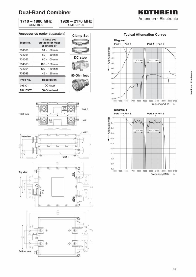
Dual-Band Combiner
1710 – 1880 MHzGSM 1800
1920 – 2170 MHzUMTS 2100
0
-10
-20
-30
-40
-50
-60
-70
-80
-90
-1001400 1500 1600 1700 1800 1900 2000 2100 2200 2300 2400
Attenuation/d
B
Frequency/MHz
1710 – 1880 1920 – 2170
0
-0.1
-0.2
-0.3
-0.4
-0.5
-0.6
-0.7
-0.8
-0.9
-1.01400 1500 1600 1700 1800 1900 2000 2100 2200 2300 2400
Atte
nuat
ion/
dB
Frequency/MHz
1920 – 21701710 – 1880
Typical Attenuation Curves
Port 1 ÷ Port 3 Port 2 ÷ Port 3
Diagram I
Diagram II
Port 1 ÷ Port 3 Port 2 ÷ Port 3
Accessories (order separately)
734360 34 – 60 mm
734361 60 – 80 mm
734362 80 – 100 mm
734363 100 – 120 mm
734364 120 – 140 mm
734365 45 – 125 mm
Clamp setType No. suitable for mast
diameter of
Clamp Set
DC stop
Type No. Description
793301 DC stop
78410367 50-Ohm load
50-Ohm load
Top view
Side view
Bottom view
¿
¡
¬
√
Unit 2
Unit 1
Unit 2
Unit 1
Front view
DCAISG
DCAISG

262
Dual-Band Combiner
1710 – 1755 / 2110 – 2155 MHzAWS
Type No. 78210469 78210808Single unit Double unit
Pass bandBand 1 (PCS) 1850 – 1910 (Rx) / 1930 – 1990 (Tx) MHzBand 2 (AWS) 1710 – 1755 (Rx) / 2110 – 2155 (Tx) MHz
Insertion lossPort PCS ÷ Port ANT < 0.3 dB (1850 – 1910 / 1930 – 1990 MHz)Port AWS ÷ Port ANT < 0.2 dB (1710 – 1755 / 2110 – 2155 MHz)
IsolationPort PCS ÷ Port AWS > 50 dB (1850 – 1910 / 1930 – 1990 MHz)
> 50 dB (1710 – 1755 / 2110 – 2155 MHz)
VSWR < 1.25 (1850 – 1910 / 1930 – 1990 MHz)< 1.25 (1710 – 1755 / 2110 – 2155 MHz)
Impedance 50 Ω
Input powerPort PCS < 250 W (1850 – 1910 / 1930 – 1990 MHz)Port AWS < 250 W (1710 – 1755 / 2110 – 2155 MHz)
Intermodulation products < –160 dBc (3rd order; with 2 x 20 W)
Power supply voltageoperational +10 … +15 V DC (Port PCS)
+10 … +30 V DC (Port AWS)survival +10 … +35 V DC
Polarity protection –48 V DC (Port PCS, Port AWS)
Max. Current 1.5 A (Port ANT)
Power supply current at PCS portoperating with dummy load 100 mA ±20 mA (+10 ... +15 V DC)
Lightning protection 8/20 μs, 20 kA; 10/350 μs, 3 kA (Port ANT)
Temperature range –40 ... +65 °C
Connectors 7-16 female (long neck)
Application Indoor or outdoor (IP 66)
Weight 2.5 kg 5 kg
Dimensions (w x h x d) 122 x 216.3 x 47 mm 122 x 216.3 x 102.6 mm(without connectors, without mounting brackets)
Technical Data
0
-0.1
-0.2
-0.3
-0.4
-0.5
-0.6
-0.7
-0.8
-0.9
-1.0
Att
en
ua
tio
n/d
B
Frequency/MHz1700 1750 1800 1850 1900 1950 2000 2050 2100 2150 2200
2110 – 2155
1850 – 1910
1930 – 1990
1710 – 1755
0
-10
-20
-30
-40
-50
-60
-70
-80
-90
-100
Att
en
ua
tio
n/d
B
Frequency/MHz
1700 1750 1800 1850 1900 1950 2000 2050 2100 2150 2200
2110 – 2155
1850 – 1910
1930 – 19901710 – 1755
Typical Attenuation Curves
Diagram I
Diagram II
1850 – 1910 / 1930 – 1990 MHzPCS
• Designed for co-siting purposes
• Enables feeder sharing
• Suitable for indoor or outdoor applications
• With fault detection and integrated switchfor multiple DC power supply
AWS
PCS
COM ANT
78210469
Port PortPCS ÷ ANT
Port PortAWS ÷ ANT
Port PortAWS ÷ ANT
Port PortPCS ÷ ANT
Port PortAWS ÷ ANT
Port PortAWS ÷ ANT

263
Mu
ltib
an
d C
om
bin
ers
Dual-Band Combiner
1710 – 1755 / 2110 – 2155 MHzAWS
Type No. 78210809 78210810Single unit Double unit
Pass bandBand 1 (PCS) 1850 – 1910 (Rx) / 1930 – 1990 (Tx) MHzBand 2 (AWS) 1710 – 1755 (Rx) / 2110 – 2155 (Tx) MHz
Insertion lossPort PCS ÷ Port ANT < 0.3 dB (1850 – 1910 / 1930 – 1990 MHz)Port AWS ÷ Port ANT < 0.2 dB (1710 – 1755 / 2110 – 2155 MHz)
IsolationPort PCS ÷ Port AWS > 50 dB (1850 – 1910 / 1930 – 1990 MHz)
> 50 dB (1710 – 1755 / 2110 – 2155 MHz)
VSWR < 1.25 (1850 – 1910 / 1930 – 1990 MHz)< 1.25 (1710 – 1755 / 2110 – 2155 MHz)
Impedance 50 Ω
Input powerPort PCS < 250 W (1850 – 1910 / 1930 – 1990 MHz)Port AWS < 250 W (1710 – 1755 / 2110 – 2155 MHz)
Intermodulation products < –160 dBc (3rd order; with 2 x 20 W)
Lightning protection 3 kA, 10/350 μs pulse
Temperature range –40 ... +65 °C
Connectors 7-16 female (long neck)
Application Indoor or outdoor (IP 66)
DC/AISG transparency By-pass between all ports (max. 2500 mA)
Weight 2.5 kg 5 kg
Dimensions (w x h x d) 122 x 216.3 x 47 mm 122 x 216.3 x 102.6 mm(without connectors, without mounting brackets)
Technical Data
0
-0.1
-0.2
-0.3
-0.4
-0.5
-0.6
-0.7
-0.8
-0.9
-1.0
Att
en
ua
tio
n/d
B
Frequency/MHz1700 1750 1800 1850 1900 1950 2000 2050 2100 2150 2200
2110 – 2155
1850 – 1910
1930 – 1990
1710 – 1755
0
-10
-20
-30
-40
-50
-60
-70
-80
-90
-100
Att
en
ua
tio
n/d
B
Frequency/MHz
1700 1750 1800 1850 1900 1950 2000 2050 2100 2150 2200
2110 – 2155
1850 – 1910
1930 – 19901710 – 1755
Typical Attenuation Curves
Diagram I
Diagram II
Port PortPCS ÷ ANT
Port PortAWS ÷ ANT
1850 – 1910 / 1930 – 1990 MHzPCS
• Designed for co-siting purposes
• Enables feeder sharing
• Suitable for indoor or outdoor applications
• DC by-pass between all ports
• External DC stop available as an accessory AWS
PCS
COM ANT
Port PortAWS ÷ ANT
78210809
Port PortPCS ÷ ANT
Port PortAWS ÷ ANT
Port PortAWS ÷ ANT
264
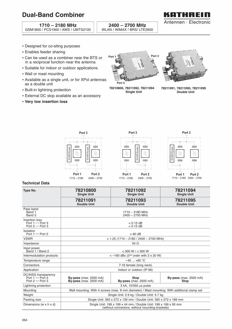
• Designed for co-siting purposes
• Enables feeder sharing
• Can be used as a combiner near the BTS or in a reciprocal function near the antenna
• Suitable for indoor or outdoor applications
• Wall or mast mounting
• Available as a single unit, or for XPol antennasas a double unit
• Built-in lightning protection
• External DC stop available as an accessory
• Very low insertion loss
Pass bandBand 1 1710 – 2180 MHzBand 2 2400 – 2700 MHz
Insertion lossPort 1 ÷ Port 3 < 0.15 dBPort 2 ÷ Port 3 < 0.15 dB
IsolationPort 1 ÷ Port 2 > 60 dB
VSWR < 1.25 (1710 – 2180 / 2400 – 2700 MHz)
Impedance 50 Ω
Input powerBand 1 / Band 2 < 300 W / < 300 W
Intermodulation products < –160 dBc (3rd order with 2 x 20 W)
Temperature range –40 ... +60 °C
Connectors 7-16 female (long neck)
Application Indoor or outdoor (IP 66)
DC/AISG transparencyPort 1 ÷ Port 3 By-pass (max. 2500 mA) Stop By-pass (max. 2500 mA)Port 2 ÷ Port 3 By-pass (max. 2500 mA) By-pass (max. 2500 mA) Stop
Lightning protection 3 kA, 10/350 μs pulse
Mounting Wall mounting: With 4 screws (max. 8 mm diameter) / Mast mounting: With additional clamp set
Weight Single Unit: 2.9 kg / Double Unit: 5.7 kg
Packing size Single Unit: 392 x 272 x 139 mm / Double Unit: 392 x 272 x 189 mm
Dimensions (w x h x d) Single Unit: 199 x 199 x 44 mm / Double Unit: 199 x 199 x 95 mm(without connectors, without mounting brackets)
Type No. 78210800 78211092 78211094Single Unit Single Unit Single Unit
78211091 78211093 78211095Double Unit Double Unit Double Unit
Technical Data
78210800, 78211092, 78211094Single Unit
78211091, 78211093, 78211095Double Unit
Port 1
Port 2
Port 3
Dual-Band Combiner
1710 – 2180 MHzGSM1800 / PCS1900 / AWS / UMTS2100
2400 – 2700 MHzWLAN / WiMAX / BRS/ LTE2600
1710 – 2180 2400 – 2700 1710 – 2180 2400 – 2700 1710 – 2180 2400 – 2700
265
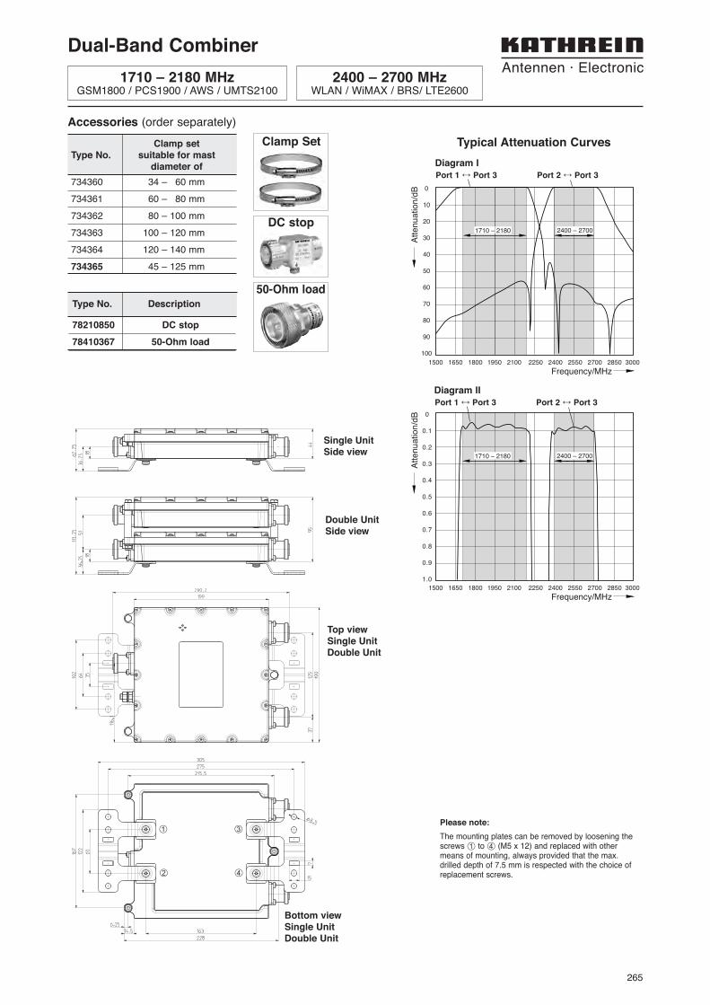
Accessories (order separately)
734360 34 – 60 mm
734361 60 – 80 mm
734362 80 – 100 mm
734363 100 – 120 mm
734364 120 – 140 mm
734365 45 – 125 mm
Clamp setType No. suitable for mast
diameter of
Clamp Set
DC stop
Type No. Description
78210850 DC stop
78410367 50-Ohm load
50-Ohm load
Dual-Band Combiner
1710 – 2180 MHzGSM1800 / PCS1900 / AWS / UMTS2100
2400 – 2700 MHzWLAN / WiMAX / BRS/ LTE2600
Typical Attenuation Curves
Diagram I
0
10
20
30
40
50
60
70
80
90
100
Atte
nuat
ion/
dB
Frequency/MHz1500 1650 1800 1950 2100 2250 2400 2550 2700 2850 3000
2400 – 27001710 – 2180
0
0.1
0.2
0.3
0.4
0.5
0.6
0.7
0.8
0.9
1.0
Atte
nuat
ion/
dB
Frequency/MHz1500 1650 1800 1950 2100 2250 2400 2550 2700 2850 3000
2400 – 27001710 – 2180
Port 1 ÷ Port 3 Port 2 ÷ Port 3
Diagram II
Port 1 ÷ Port 3 Port 2 ÷ Port 3
Top viewSingle UnitDouble Unit
Single UnitSide view
Bottom viewSingle UnitDouble Unit
Double UnitSide view
¿ ¬
¡ √
The mounting plates can be removed by loosening thescrews ¿ to √ (M5 x 12) and replaced with othermeans of mounting, always provided that the max.drilled depth of 7.5 mm is respected with the choice ofreplacement screws.
Please note: