Embed Size (px)
Citation preview
WDM
DWDM, CWDM
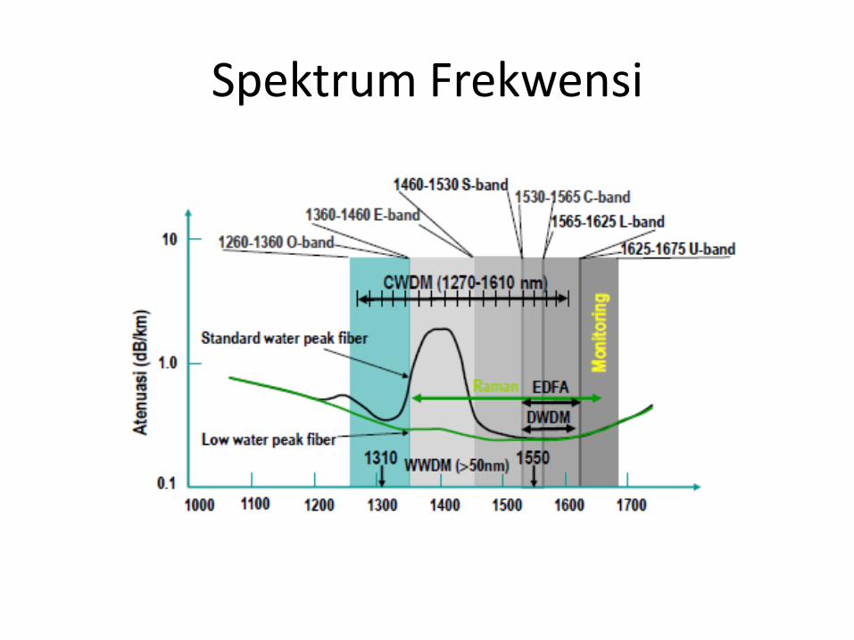
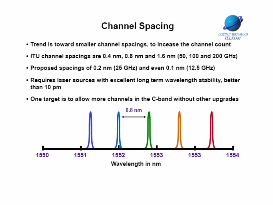
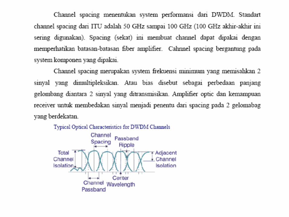
Spektrum Frekwensi
Mengapa WDM
• Tahun 1990 WDM mulai memainkan peranbesar dalam jaringan telekomunikasi.
• Permintaan kapasitas link yang besar danterbatasnya instalasi serat optik untuk lajusinyal optik yang cepat.
• Awalnya bekerja dengan baik pada laju bit mencapai 2,5 Gb/s (Optical Core 48). Kedepankecepatan level multiplexing berikutnyamencapai 10 Gb/s dengan OC 192.
5
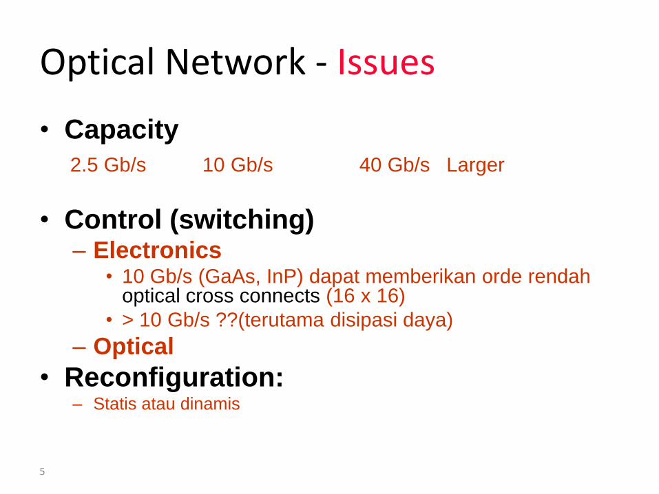
Optical Network - Issues
• Capacity
2.5 Gb/s 10 Gb/s 40 Gb/s Larger
• Control (switching)– Electronics
• 10 Gb/s (GaAs, InP) dapat memberikan orde rendahoptical cross connects (16 x 16)
• > 10 Gb/s ??(terutama disipasi daya)
– Optical
• Reconfiguration: – Statis atau dinamis
Sejarah WDM
Teknologi WDM
NTT tahun 2010 tanggal 25 Maret telah mampu mencapai
transmisi 69,1 Tb/s dengan menggunakan WDM 432 kanal kapasitas171 Gb/s dan untuk long haul panjang serat optik singlemode 240 km.
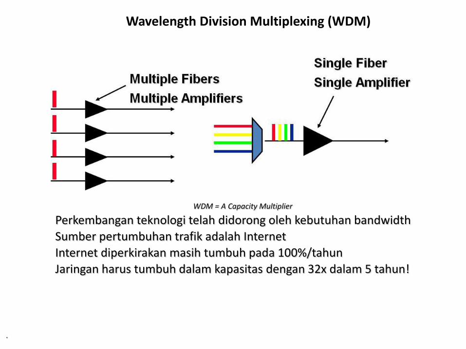
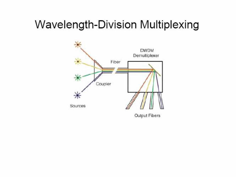
Wavelength Division Multiplexing (WDM)
.
WDM = A Capacity Multiplier
Perkembangan teknologi telah didorong oleh kebutuhan bandwidth
Sumber pertumbuhan trafik adalah Internet
Internet diperkirakan masih tumbuh pada 100%/tahun
Jaringan harus tumbuh dalam kapasitas dengan 32x dalam 5 tahun!
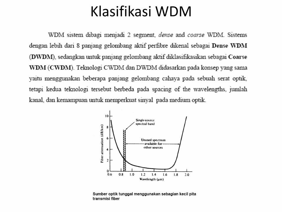
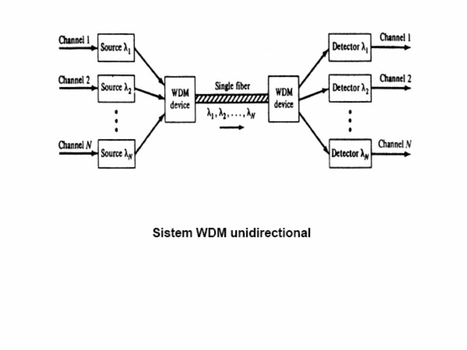
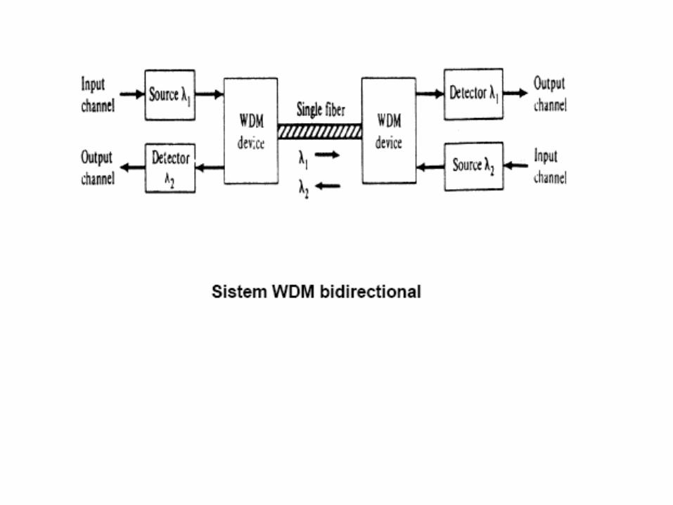
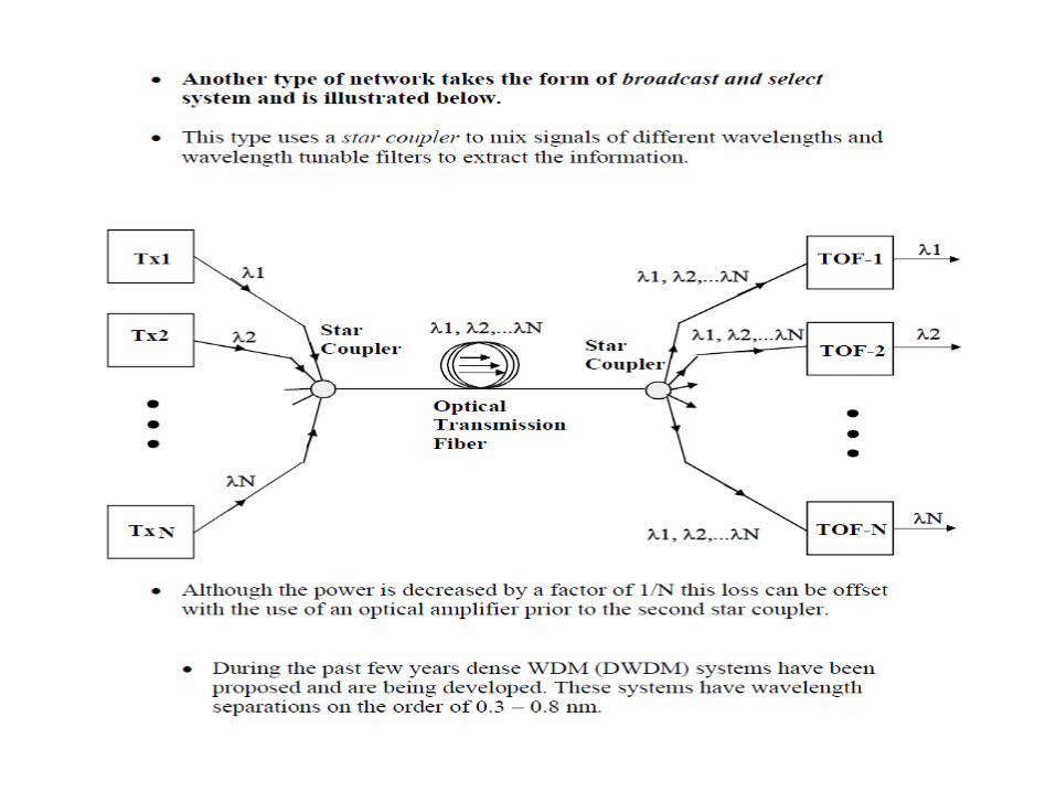
Klasifikasi WDM
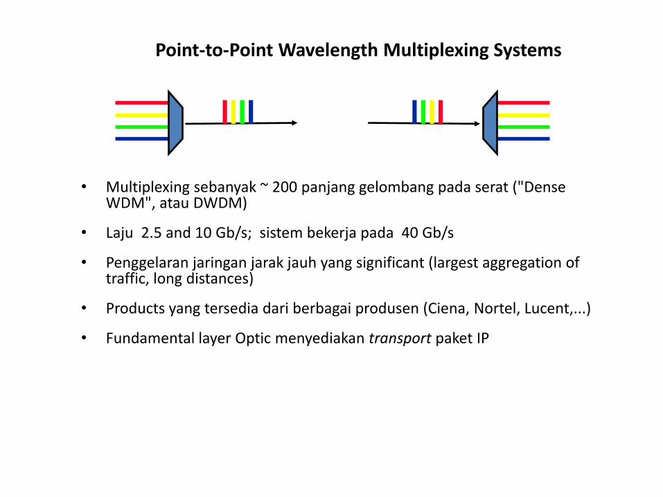
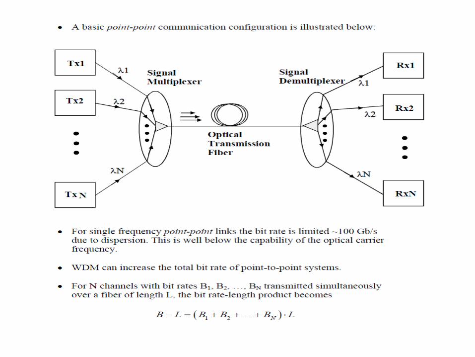
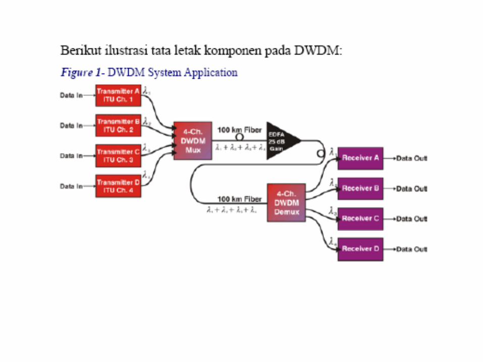
Point-to-Point Wavelength Multiplexing Systems
• Multiplexing sebanyak ~ 200 panjang gelombang pada serat ("Dense WDM", atau DWDM)
• Laju 2.5 and 10 Gb/s; sistem bekerja pada 40 Gb/s
• Penggelaran jaringan jarak jauh yang significant (largest aggregation of traffic, long distances)
• Products yang tersedia dari berbagai produsen (Ciena, Nortel, Lucent,...)
• Fundamental layer Optic menyediakan transport paket IP
17
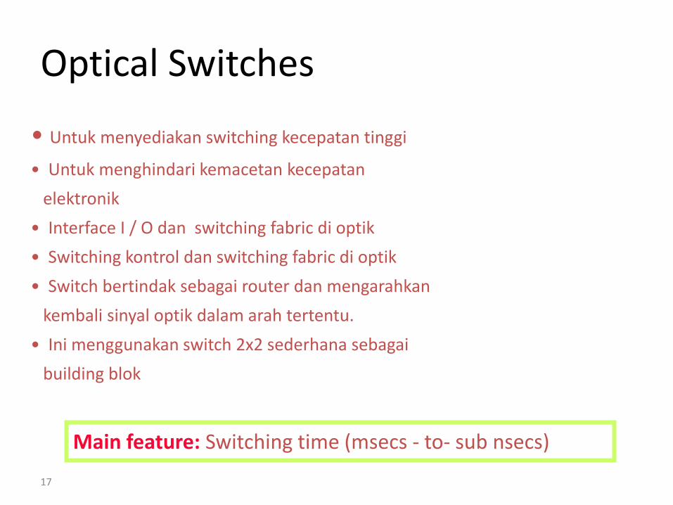
Optical Switches
• Untuk menyediakan switching kecepatan tinggi
• Untuk menghindari kemacetan kecepatan
elektronik
• Interface I / O dan switching fabric di optik
• Switching kontrol dan switching fabric di optik
• Switch bertindak sebagai router dan mengarahkan
kembali sinyal optik dalam arah tertentu.
• Ini menggunakan switch 2x2 sederhana sebagai
building blok
Main feature: Switching time (msecs - to- sub nsecs)
18
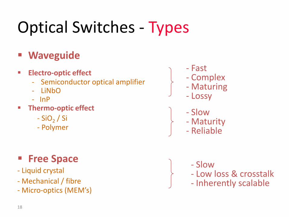
Optical Switches - Types
Waveguide
Electro-optic effect- Semiconductor optical amplifier- LiNbO- InP
Thermo-optic effect
- SiO2 / Si- Polymer
Free Space- Liquid crystal
- Mechanical / fibre- Micro-optics (MEM’s)
- Fast- Complex- Maturing- Lossy
- Slow- Maturity- Reliable
- Slow- Low loss & crosstalk- Inherently scalable
19
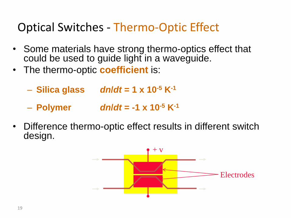
Optical Switches - Thermo-Optic Effect
• Some materials have strong thermo-optics effect that could be used to guide light in a waveguide.
• The thermo-optic coefficient is:
– Silica glass dn/dt = 1 x 10⁻⁵ K-1
– Polymer dn/dt = -1 x 10⁻⁵ K-1
• Difference thermo-optic effect results in different switch design.
+ v
Electrodes
20
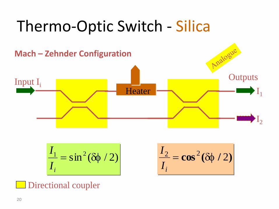
Thermo-Optic Switch - Silica
Directional coupler
)2/(sin 21 iI
I)/(cos 222
iI
I
Input IiI1
I2
Outputs
Mach – Zehnder Configuration
Heater
21
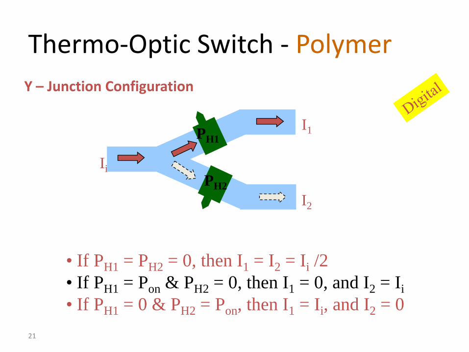
Thermo-Optic Switch - Polymer
• If PH1 = PH2 = 0, then I1 = I2 = Ii /2
• If PH1 = Pon & PH2 = 0, then I1 = 0, and I2 = Ii
• If PH1 = 0 & PH2 = Pon, then I1 = Ii, and I2 = 0
Ii
I1
I2
PH1
PH2
Y – Junction Configuration
22
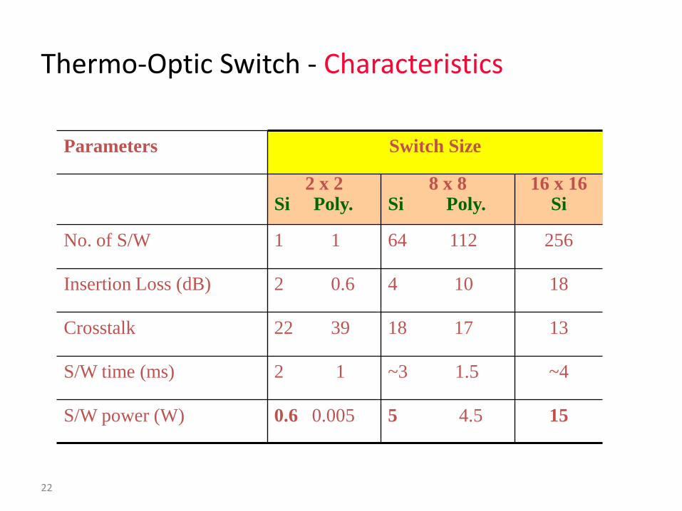
Thermo-Optic Switch - Characteristics
155 4.50.6 0.005S/W power (W)
~4~3 1.52 1S/W time (ms)
1318 1722 39Crosstalk
184 102 0.6Insertion Loss (dB)
25664 1121 1No. of S/W
16 x 16Si
8 x 8Si Poly.
2 x 2Si Poly.
Switch SizeParameters
23
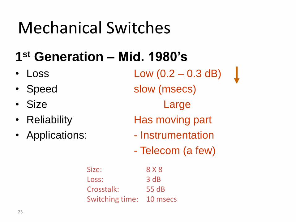
Mechanical Switches
1st Generation – Mid. 1980’s
• Loss Low (0.2 – 0.3 dB)
• Speed slow (msecs)
• Size Large
• Reliability Has moving part
• Applications: - Instrumentation
- Telecom (a few)
Size: 8 X 8Loss: 3 dBCrosstalk: 55 dBSwitching time: 10 msecs
24
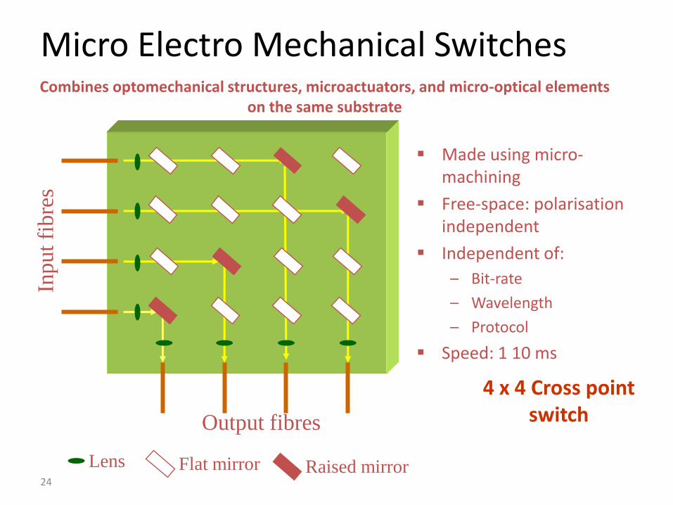
Micro Electro Mechanical SwitchesIn
put
fibre
s
Output fibres
Lens Flat mirror Raised mirror
Made using micro-machining
Free-space: polarisation independent
Independent of:
– Bit-rate
– Wavelength
– Protocol
Speed: 1 10 ms
4 x 4 Cross pointswitch
Combines optomechanical structures, microactuators, and micro-optical elements on the same substrate
25
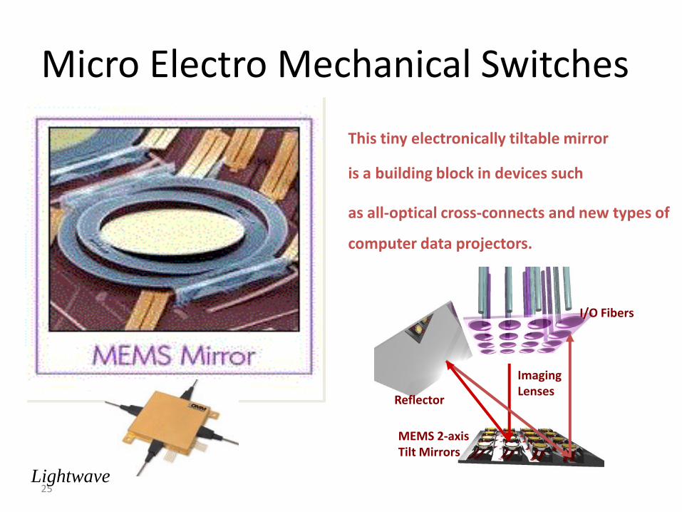
Micro Electro Mechanical Switches
This tiny electronically tiltable mirror
is a building block in devices such
as all-optical cross-connects and new types of
computer data projectors.
Lightwave
I/O Fibers
Imaging Lenses
Reflector
MEMS 2-axis Tilt Mirrors
26
Micro Electro Mechanical Switches
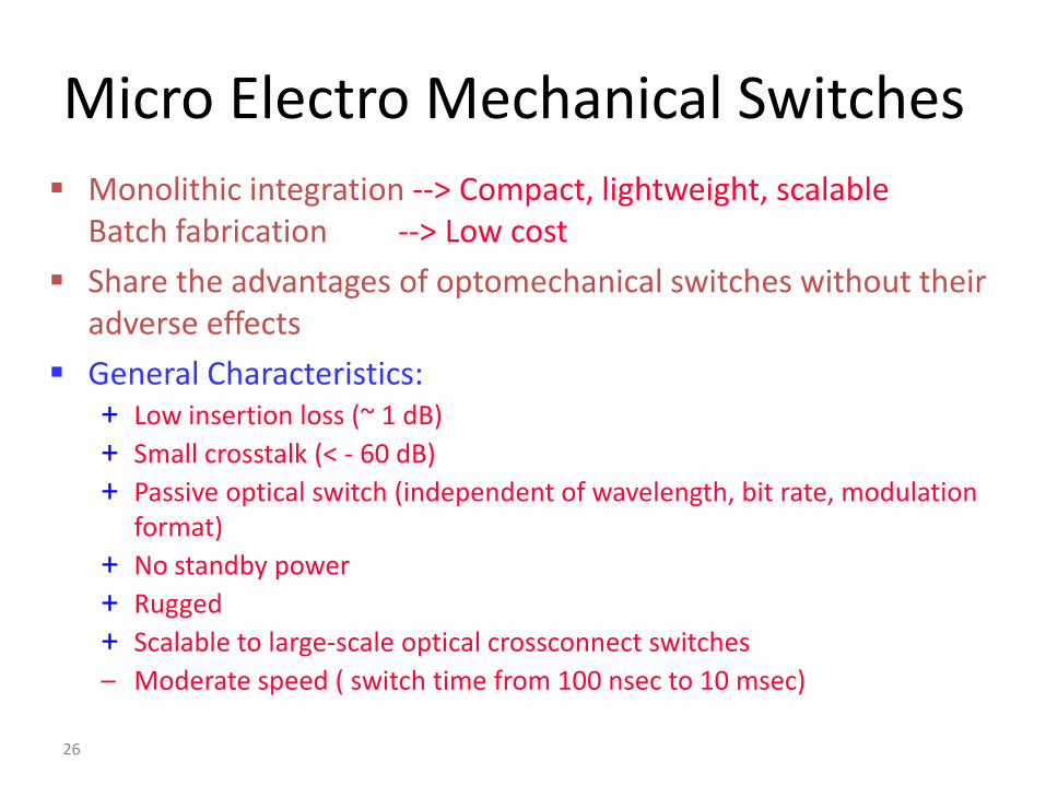
Monolithic integration --> Compact, lightweight, scalableBatch fabrication --> Low cost
Share the advantages of optomechanical switches without their adverse effects
General Characteristics:+ Low insertion loss (~ 1 dB)
+ Small crosstalk (< - 60 dB)
+ Passive optical switch (independent of wavelength, bit rate, modulation format)
+ No standby power
+ Rugged
+ Scalable to large-scale optical crossconnect switches
– Moderate speed ( switch time from 100 nsec to 10 msec)
27
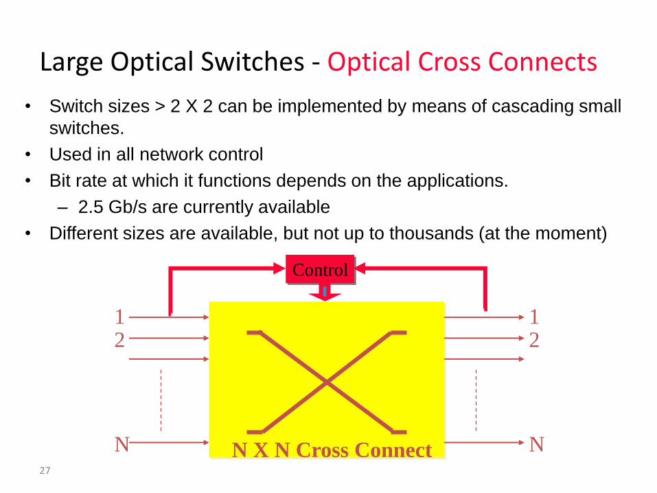
Large Optical Switches - Optical Cross Connects
• Switch sizes > 2 X 2 can be implemented by means of cascading small
switches.
• Used in all network control
• Bit rate at which it functions depends on the applications.
– 2.5 Gb/s are currently available
• Different sizes are available, but not up to thousands (at the moment)
12
N
12
NN X N Cross Connect
Control
28
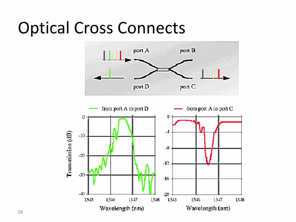
Optical Cross Connects
29
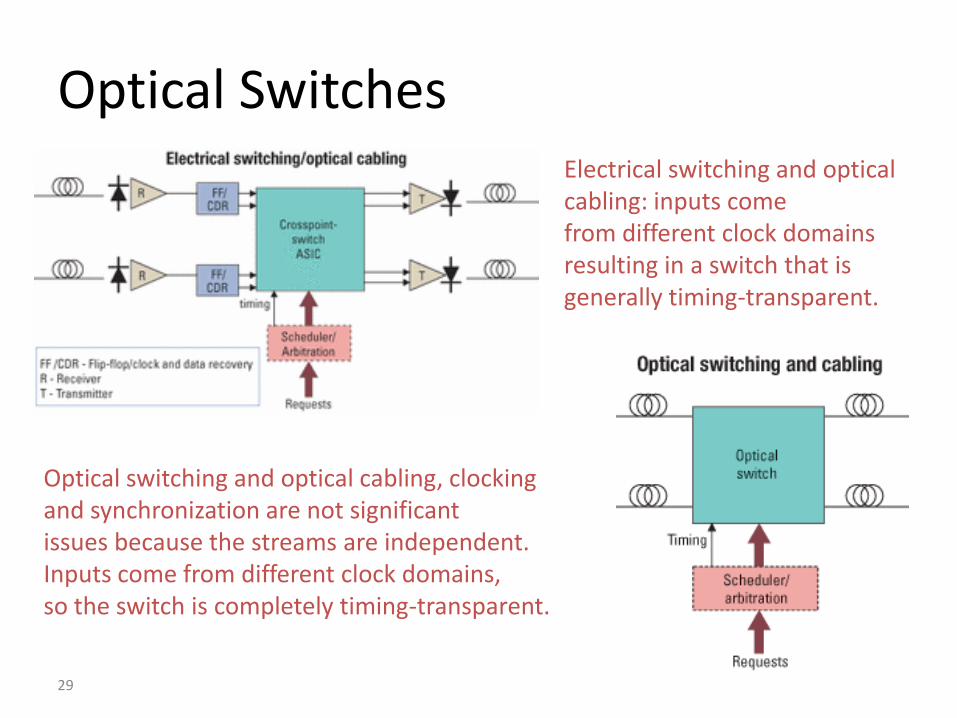
Optical SwitchesElectrical switching and optical cabling: inputs come from different clock domains resulting in a switch that is generally timing-transparent.
Optical switching and optical cabling, clocking and synchronization are not significant issues because the streams are independent. Inputs come from different clock domains, so the switch is completely timing-transparent.
30
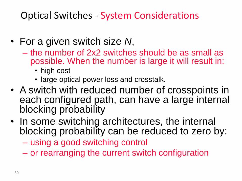
• For a given switch size N, – the number of 2x2 switches should be as small as
possible. When the number is large it will result in:• high cost
• large optical power loss and crosstalk.
• A switch with reduced number of crosspoints in each configured path, can have a large internal blocking probability
• In some switching architectures, the internal blocking probability can be reduced to zero by:– using a good switching control
– or rearranging the current switch configuration
Optical Switches - System Considerations
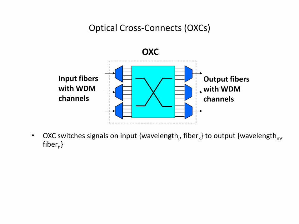
Optical Cross-Connects (OXCs)
• OXC switches signals on input {wavelengthi, fiberk} to output {wavelengthm, fibern}
Input fiberswith WDMchannels
OXC
Output fiberswith WDMchannels
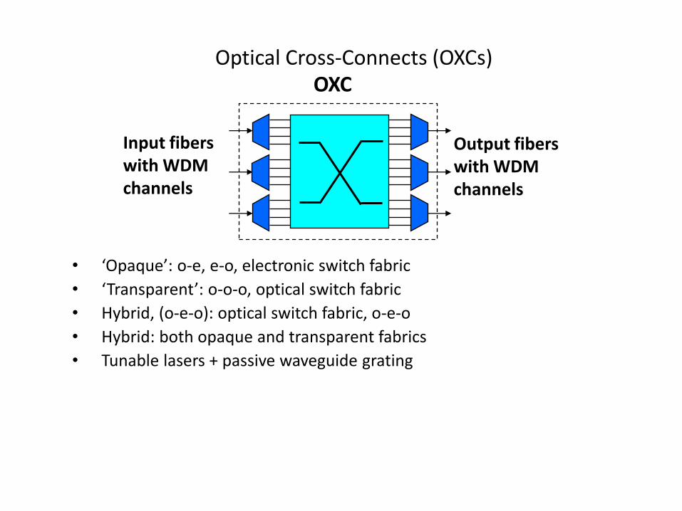
Optical Cross-Connects (OXCs)
• ‘Opaque’: o-e, e-o, electronic switch fabric
• ‘Transparent’: o-o-o, optical switch fabric
• Hybrid, (o-e-o): optical switch fabric, o-e-o
• Hybrid: both opaque and transparent fabrics
• Tunable lasers + passive waveguide grating
Input fiberswith WDMchannels
OXC
Output fiberswith WDMchannels
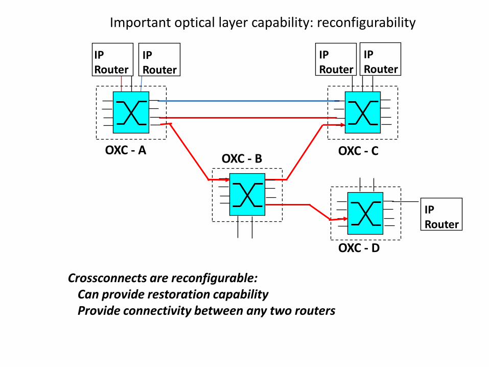
Important optical layer capability: reconfigurability
IPRouter
IPRouter
IPRouter
OXC - AOXC - B
OXC - C
Crossconnects are reconfigurable: Can provide restoration capabilityProvide connectivity between any two routers
IPRouter
OXC - D
IPRouter
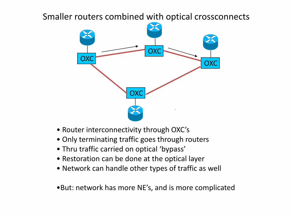
Smaller routers combined with optical crossconnects
• Router interconnectivity through OXC’s• Only terminating traffic goes through routers• Thru traffic carried on optical ‘bypass’ • Restoration can be done at the optical layer• Network can handle other types of traffic as well
•But: network has more NE’s, and is more complicated
OXCOXC
OXC
OXC
35
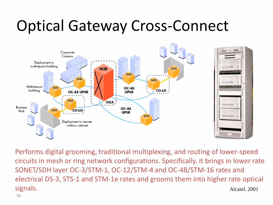
Optical Gateway Cross-Connect
Performs digital grooming, traditional multiplexing, and routing of lower-speed circuits in mesh or ring network configurations. Specifically, it brings in lower rate SONET/SDH layer OC-3/STM-1, OC-12/STM-4 and OC-48/STM-16 rates and electrical DS-3, STS-1 and STM-1e rates and grooms them into higher rate optical signals. Alcatel. 2001
36
40 G mod
40 G mod
40 G mod
40 G mod
T-Tx
T-Tx
T-Tx
T-Tx
40G Rx
40G Rx
40G Rx
40G Rx
Clock
Buffer
Sche-
duler
From Input Port
retiming
Output
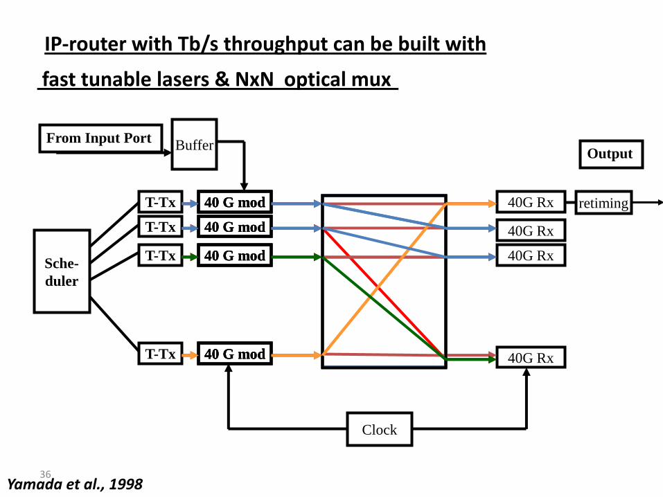
IP-router with Tb/s throughput can be built with
fast tunable lasers & NxN optical mux
Yamada et al., 1998
40 G mod
40 G mod
40 G mod
40 G mod
40 G mod
40 G mod
40 G mod
40 G mod
37
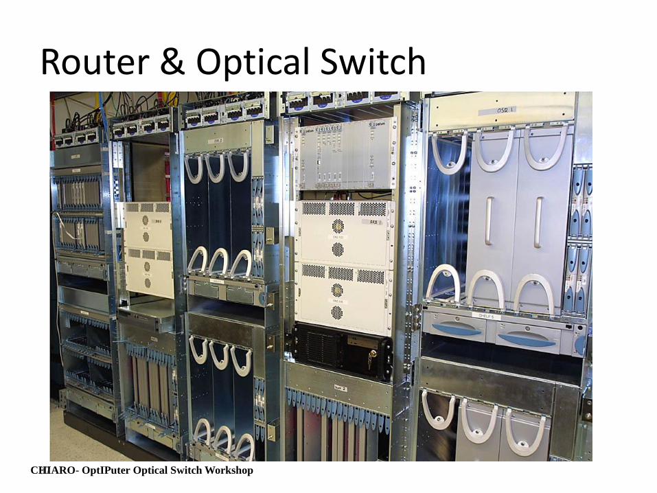
Router & Optical Switch
CHIARO- OptIPuter Optical Switch Workshop
38
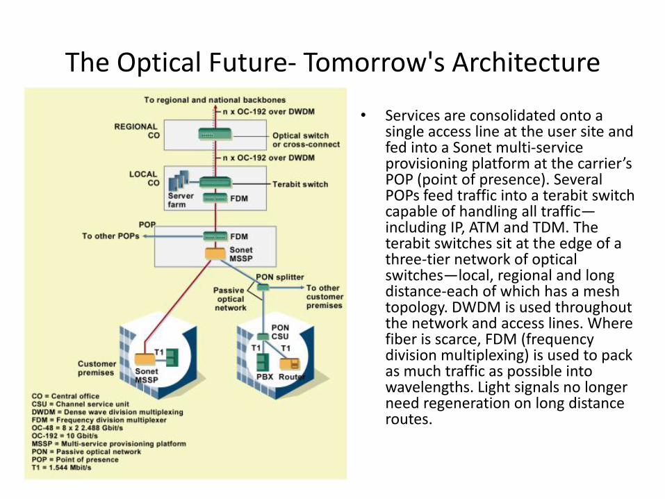
The Optical Future- Tomorrow's Architecture
• Services are consolidated onto a single access line at the user site and fed into a Sonet multi-service provisioning platform at the carrier’s POP (point of presence). Several POPs feed traffic into a terabit switch capable of handling all traffic—including IP, ATM and TDM. The terabit switches sit at the edge of a three-tier network of optical switches—local, regional and long distance-each of which has a mesh topology. DWDM is used throughout the network and access lines. Where fiber is scarce, FDM (frequency division multiplexing) is used to pack as much traffic as possible into wavelengths. Light signals no longer need regeneration on long distance routes.
39
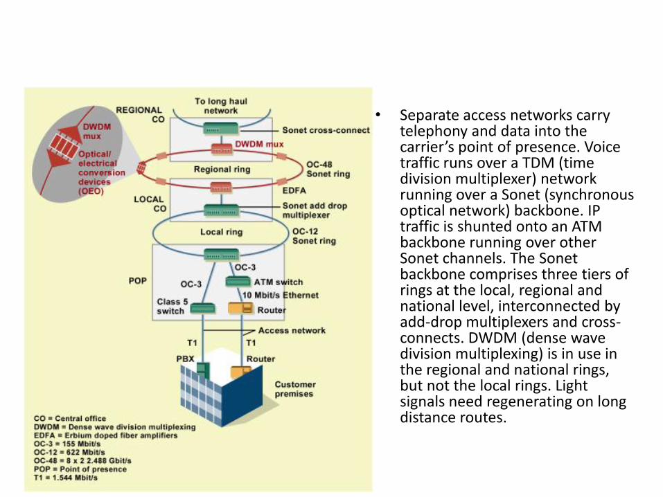
• Separate access networks carry telephony and data into the carrier’s point of presence. Voice traffic runs over a TDM (time division multiplexer) network running over a Sonet (synchronous optical network) backbone. IP traffic is shunted onto an ATM backbone running over other Sonet channels. The Sonet backbone comprises three tiers of rings at the local, regional and national level, interconnected by add-drop multiplexers and cross-connects. DWDM (dense wave division multiplexing) is in use in the regional and national rings, but not the local rings. Light signals need regenerating on long distance routes.
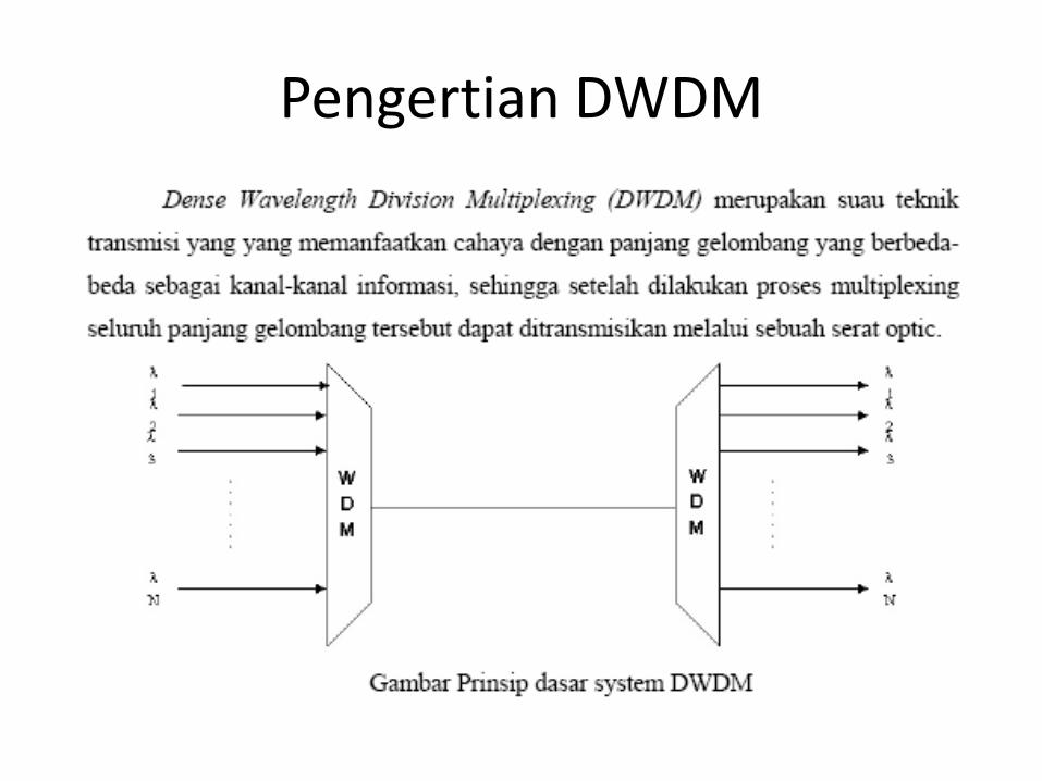
Pengertian DWDM
Definisi
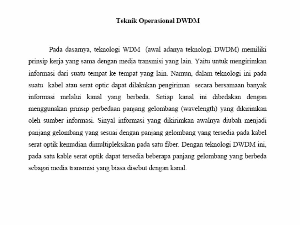
Teknologi DWDM
Perkembangan DWDM
Perangkat DWDM
Perangkat DWDM
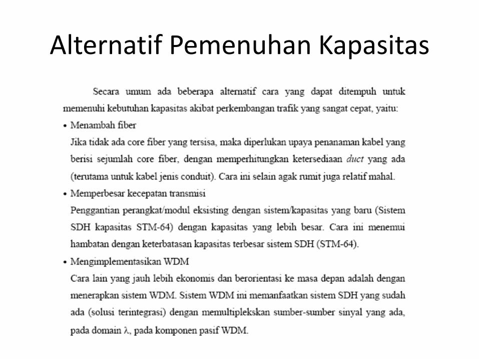
Alternatif Pemenuhan Kapasitas
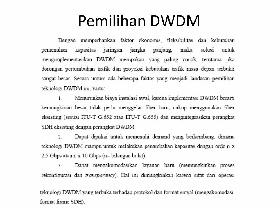
Pemilihan DWDM
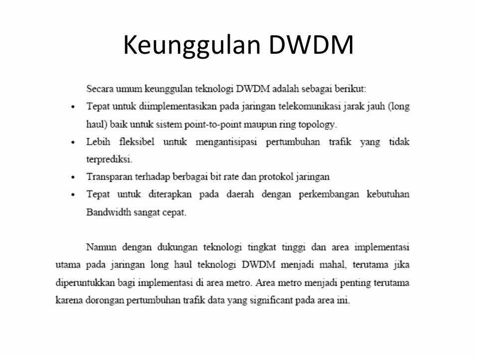
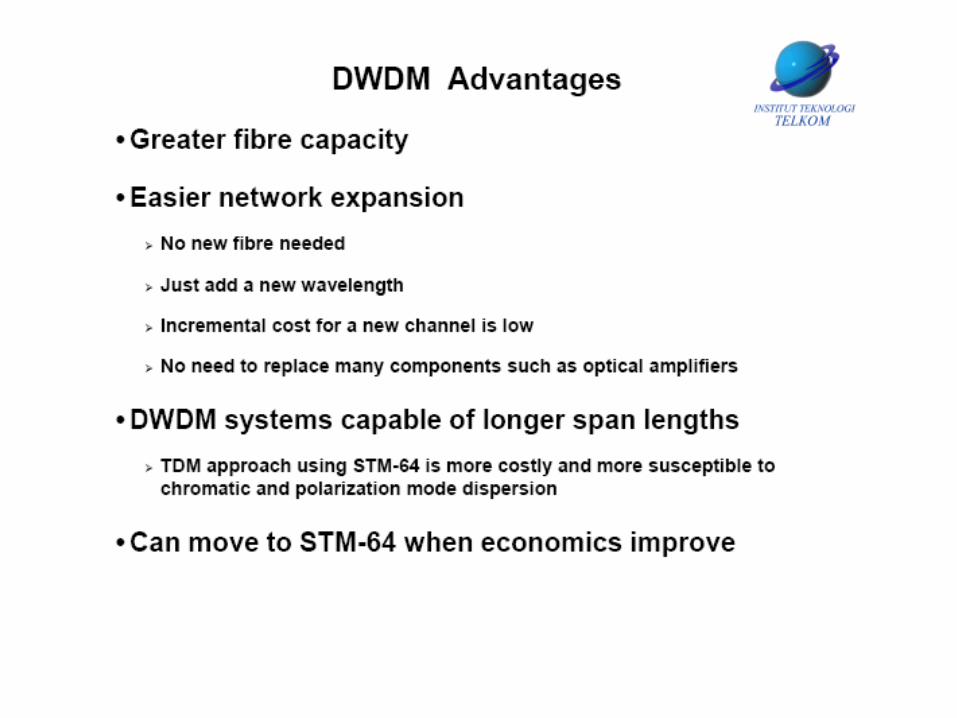
Keunggulan DWDM
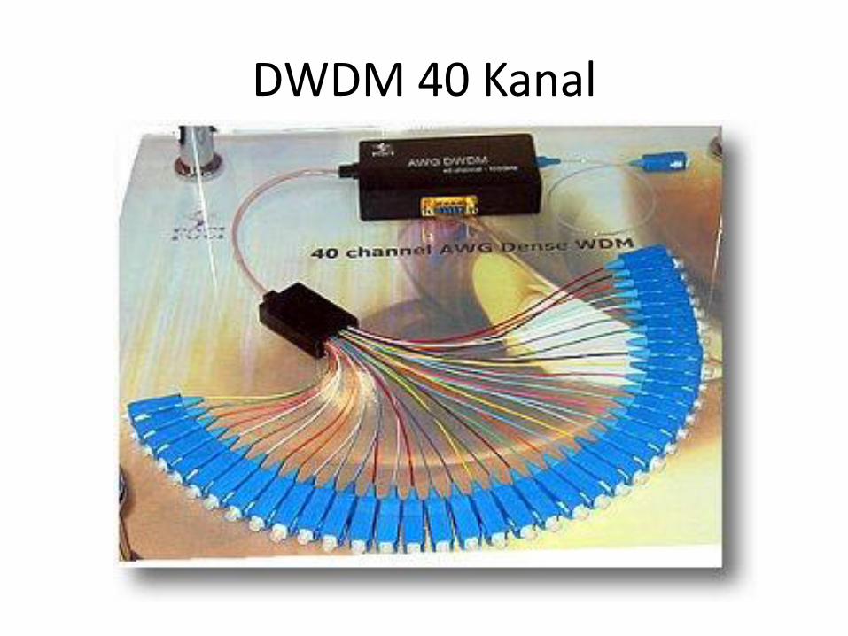
DWDM 40 Kanal