Embed Size (px)
Citation preview
eçêáòçåjìäíáJãÉÇá~=aêó=fã~ÖÉê=
rëÉêÛë=j~åì~ä
∆
Codonics® Catalog Number HORIZON MNLUMay 21, 2018Version 3.0.2 USB Flash DriveVersion 2.1.3 ZIP Disk
Codonics, Inc.17991 Englewood DriveMiddleburg Heights, OH 44130 USA440.243.1198 Phone440.243.1334 FaxEmail [email protected]
Copyright © 2004 – 2018 by Codonics, Inc. All rights reserved, worldwide. Printed in the U.S.A. Part Number 905-019-102.
No part of this document may be copied or reproduced in any form by any means without prior written consent of Codonics, Inc., 17991 Englewood Dr., Middleburg Heights, Ohio 44130 U.S.A.
Although every effort has been made to ensure the accuracy of this document, Codonics, Inc. assumes no responsibility for any errors that may appear. Codonics, Inc. makes no commitment to update nor to keep current the information contained in this document.
Horizon Patents: www.codonics.co/ip/patents
Horizon, DirectVista, ChromaVista, the Codonics logo, and “We bring the future into focus” are registered trademarks, and Codonics, Variable Multiformatting, VMF, Fixed Multiformatting, FMF, Medical Color Matching, MCM, SlideMaker, and Bracketing are trademarks of Codonics, Inc.
Windows and Windows NT are registered trademarks of Microsoft Corporation.
PostScript is a registered trademark of Adobe Systems Incorporated.
Apple and Macintosh are trademarks of Apple Computer, Inc., registered in the U.S. and other countries.
UNIX is a registered trademark of The Open Group.
Linux is a registered trademark of Linus Torvalds.
Zip is a registered trademark of Iomega Corporation.
StuffIt is a trademark of Aladdin Systems, Inc.
PKZIP is a registered trademark of PKWARE, Inc.
Intel is a registered trademark of Intel Corporation or its subsidiaries in the United States and other countries.
All other registered and unregistered trademarks are the property of their respective
owners.
European Authorized Representative:
CEpartner4U BVEsdoornlaan 13,3951 DB MaarnThe Netherlands www.cepartner4u.com
CAUTION Approved FDA Class 2 device - Federal law restricts this device to be sold
for use by or on the order of a physician.
Co
nte
nts
`çåíÉåíëContents
Preface
Conventions Used in This Manual ................................................................. xi
Bulleted Lists........................................................................................... xi
Numbered Steps ..................................................................................... xi
Control Panel Navigation ....................................................................... xii
Control Panel Keys ................................................................................ xii
Control Panel Menu Options .................................................................. xii
Notes and Tips ....................................................................................... xii
Cautions and Warnings......................................................................... xiii
Text Files and Displayed Text............................................................... xiii
User Data .............................................................................................. xiii
Important Information and Filenames ................................................... xiv
New Terms............................................................................................ xiv
Purpose and Scope ...................................................................................... xv
Product Information ..................................................................................... xvi
Warnings and Limitations of Use................................................................ xvii
Location of Safety and Compliance Labels.......................................... xvii
Voltage Warning.................................................................................. xviii
Dangers Electriques.............................................................................. xix
Laser Warning....................................................................................... xxi
Dangers au Laser................................................................................. xxii
Temperature Warning ......................................................................... xxiii
Dangers Température ......................................................................... xxiii
Compliance ......................................................................................... xxiv
Serial Number, Configuration, Date Code, and Modification Codes .... xxv
ESD Caution ....................................................................................... xxvi
Horizon Imager User’s Manual iii
iv
Potential for Radio Frequency Interference on Imager Operation ...... xxvi
Potential for Radio and Television Interference ................................. xxvii
Guidance Regarding Electromagnetic Emissions and Immunity ....... xxviii
Safety Precautions .............................................................................. xxxi
Précaution d’Emploi ........................................................................... xxxiii
Location Precautions.......................................................................... xxxv
Environnement de Fonctionnement .................................................. xxxvi
Cleaning Precautions ........................................................................ xxxvii
Précautions d’Entretien .................................................................... xxxviii
Media ............................................................................................... xxxviii
Codonics Paper/White Film Media.................................................... xxxix
File Transfer via FTP and LPR................................................................ xl
Color Management.................................................................................. xl
Image Scaling ........................................................................................ xli
Hardware Variations............................................................................... xli
Disposal Requirements ............................................................................... xlii
Conditions et Règles d’Utilisation.......................................................... xlii
European Disposal Requirements ........................................................ xlii
Indications for Use...................................................................................... xliii
Chapter 1: Introduction
Welcome and Congratulations ................................................................... 1-1
Imager Features ......................................................................................... 1-2
State-of-the-Art Printing Technology .................................................... 1-2
Small Footprint ..................................................................................... 1-2
Wide Variety of Media Types and Sizes............................................... 1-3
Easy Access from a Variety of Image Sources .................................... 1-3
Support for Major Image File Formats ................................................. 1-4
Image Formatting and Enhancement Capabilities ............................... 1-5
Adding Captions to Printed Sheets ...................................................... 1-5
Easy Feature Upgrade ......................................................................... 1-5
Easy Imager Personality Swap ............................................................ 1-6
Easy Software Updates and Configuration Backups............................ 1-6
Contents
Co
nte
nts
Chapter 2: Setting Up the Imager
Preparing for Installation............................................................................. 2-1
Installing the Imager ................................................................................... 2-2
Connecting the Ethernet Cable .................................................................. 2-8
Powering On the Imager—First Time ....................................................... 2-10
Cleaning the Platen............................................................................ 2-11
Network Settings—Simple Network.......................................................... 2-12
Specifying the Imager’s IP Address ................................................... 2-13
Determining an IP Address.......................................................... 2-13
Specifying the Imager’s IP Address at the Control Panel ............ 2-14
Specifying IP Addresses for Other Devices on the Network .............. 2-17
Loading Media .......................................................................................... 2-17
Printing the Imager Status Test Print........................................................ 2-18
Testing Network Printing .......................................................................... 2-19
Changing the Service Password .............................................................. 2-20
Adjusting Image Appearance ................................................................... 2-20
Saving the Configuration Settings ............................................................ 2-20
Saving the Configuration Settings to Backup Media .......................... 2-21
Managing Your Backup Media ........................................................... 2-23
Restoring the Configuration Settings from Backup Media ................. 2-24
Moving Smart Card to a Swap Imager...................................................... 2-25
Preparing the Imager for Shipment .......................................................... 2-26
Chapter 3: Basic Imager Operations
Horizon Imager Components...................................................................... 3-1
Powering the Imager On and Off ................................................................ 3-3
Powering On the Imager ...................................................................... 3-3
Observing the Imager’s Operating Status in the Status Screen ........... 3-4
Common Cassette Status Messages............................................. 3-5
Color Ribbon Status....................................................................... 3-6
Powering Off the Imager ...................................................................... 3-7
Rebooting the Imager........................................................................... 3-9
Understanding the Control Panel ............................................................. 3-10
Control Panel Indicators..................................................................... 3-11
Horizon Imager User’s Manual v
vi
Alert and Fault Messages and the Fault Tone.................................... 3-12
Control Panel Display......................................................................... 3-13
Status Screen .............................................................................. 3-13
Main Menu ................................................................................... 3-14
Control Panel Keys ............................................................................ 3-16
Navigating the Control Panel Display................................................. 3-18
Cancelling Your Changes in a Screen ......................................... 3-21
Exiting the Menus ........................................................................ 3-21
Summary of Menu Conventions......................................................... 3-21
The Pause State....................................................................................... 3-22
Pausing the Imager ............................................................................ 3-22
Resuming Printing.............................................................................. 3-23
Using Online Help..................................................................................... 3-23
Chapter 4: Media Handling and Storage
Overview..................................................................................................... 4-1
Supply Slots and Cassettes ................................................................. 4-1
Viewing the Status of a Supply Slot ............................................... 4-3
Receive Trays ...................................................................................... 4-3
Inserting or Changing Cassettes ................................................................ 4-4
Determining Which Cassette to Use........................................................... 4-6
Handling and Storing Media ....................................................................... 4-7
Break-Off Leaders (ChromaVista Only) ............................................... 4-7
Changing the Ribbon (ChromaVista).......................................................... 4-8
Ordering Media ......................................................................................... 4-12
Chapter 5: Printing from DICOM Applications
Introduction to DICOM................................................................................ 5-1
DICOM Conformance Statement ......................................................... 5-2
How a DICOM Print Job Is Processed ................................................. 5-3
Configuring the DICOM Application............................................................ 5-4
Sending a DICOM Print Job ....................................................................... 5-5
Specifying the Media Type and Size .................................................... 5-5
Using Job Settings Files with DICOM......................................................... 5-6
Contents
Co
nte
nts
Categories of Job Settings ................................................................... 5-6
Specifying a Job Settings File from a DICOM User Application........... 5-7
Hierarchy of Settings Used by the Horizon Imager .............................. 5-8
Chapter 6: Printing via PostScript
Introduction to PostScript ........................................................................... 6-2
Hierarchy of Parameter Settings Used by the Horizon Imager ............ 6-3
Specifying the Media Type and Size .................................................... 6-3
Printing from Windows Applications ........................................................... 6-4
Specifying Horizon PostScript Parameters .......................................... 6-4
Notes About Changing PostScript Parameters.............................. 6-5
Changing Horizon PostScript Parameters—Windows 98 and Me. 6-9
Changing Horizon PostScript Parameters—Windows NT........... 6-12
Changing Horizon PostScript Parameters—Windows 2000 and XP ... 6-15
Printing from Macintosh Applications........................................................ 6-16
Specifying the Horizon Media............................................................. 6-16
Specifying Horizon PostScript Parameters ........................................ 6-18
Notes About Changing PostScript Parameters............................ 6-20
Saving Horizon Print Settings as Presets in OS X ............................. 6-24
Saving Horizon Print Settings in OS 8 and 9 ..................................... 6-24
Chapter 7: Printing via FTP and LPR
Printing via FTP .......................................................................................... 7-1
Specifying the Media Type and Size Using FTP .................................. 7-4
Printing via LPR.......................................................................................... 7-5
Examples of Printing Using LPR.................................................... 7-6
Specifying the Media Type and Size Using LPR .................................. 7-6
Chapter 8: Default Print Job Settings
Changing Default Settings.......................................................................... 8-2
Changing the Default Media Type and Size......................................... 8-3
Changing Default User Settings for a Media Type ............................... 8-5
Horizon Imager User’s Manual vii
viii
Resetting to Factory-Default Settings......................................................... 8-7
Resetting the Default Media Selections ............................................... 8-7
Resetting the Default User Settings ..................................................... 8-8
Chapter 9: Adjusting Image Appearance
ChromaVista and Grayscale Images.......................................................... 9-1
Guidelines for Viewing Printed Images....................................................... 9-2
General Bracketing Guidelines................................................................... 9-2
GCS Bracketing Sheets.............................................................................. 9-3
Printing GCS Bracketing Sheets Using DICOM................................... 9-4
Printing GCS Bracketing Sheets Using PostScript .............................. 9-5
DirectVista Adjustments ....................................................................... 9-5
ChromaVista Adjustments.................................................................... 9-7
Guidelines for Selecting Saturation Setting.......................................... 9-8
MCM Bracketing Sheets............................................................................. 9-9
Printing MCM Bracketing Sheets Using DICOM ................................ 9-11
Printing MCM Bracketing Sheets Using PostScript............................ 9-11
Chapter 10: Preventive Maintenance
Recommended Maintenance Schedule.................................................... 10-1
Horizon Cleaning Kits......................................................................... 10-2
Cleaning Print Head and Nosepiece ........................................................ 10-3
Cleaning the Platen and Donor Guide Bar ............................................... 10-8
Cleaning the Pick Tires........................................................................... 10-13
Cleaning the Barcode Reader Window .................................................. 10-15
General Cleaning Procedures ................................................................ 10-18
Cleaning the Area Around the Imager.............................................. 10-18
Cleaning the Receive Trays ............................................................. 10-18
Cleaning the Basement.................................................................... 10-19
Chapter 11: Calibration
Film Calibration (DirectVista Film Only).................................................... 11-2
Contents
Co
nte
nts
Chapter 12: Troubleshooting
Sources of Status Information .................................................................. 12-1
Control Panel ..................................................................................... 12-1
Error Log ............................................................................................ 12-1
Online Help for Displayed Messages ................................................. 12-1
Printing an Imager Status Test Print ................................................... 12-2
Troubleshooting Tables ............................................................................ 12-2
Status Message Tables .......................................................................... 12-12
Common Cassette Status Messages ............................................... 12-12
Color Ribbon Status ......................................................................... 12-13
Clearing a Sheet Jam ............................................................................. 12-14
Clearing a Jam from a Cassette....................................................... 12-16
Clearing a Jam from the Printing Area ............................................. 12-19
Reinstalling Media Guides ............................................................... 12-22
Purging Print Jobs .................................................................................. 12-25
Manually Entering a Cassette Barcode .................................................. 12-26
Viewing Logged Error Messages............................................................ 12-28
Viewing Imager Information Online ........................................................ 12-29
Contacting Technical Support ................................................................ 12-30
Anonymous FTP .............................................................................. 12-31
Chapter A: Menu Hierarchy
Chapter B: Specifications
Specifications (English) .............................................................................. B-1
Specifications (French) ............................................................................... B-4
Chapter C: System Job Settings Files
Chapter D: Print Job Parameters
Chapter : Index
Horizon Imager User’s Manual ix

x
Contents
Pre
fac
e
mêÉÑ~ÅÉ
_ìääÉíÉÇ=iáëíë
Bullets are used to display a list of nonprocedural items. For example:
The control panel contains:
• A display panel
• Keys
• Indicators
kìãÄÉêÉÇ=píÉéë
The 8 icon indicates the beginning of a procedure. The steps
in a procedure are numbered. For example:
1. Press the key.
The Main Menu displays on the control panel. The selector arrow ( � ) automatically points to the first menu option.
2. To scroll through the menu options, press the and keys.
The selector arrow ( � ) moves up and down through the list. The bottom portion of the control panel display shows a message associated with the currently selected menu option.
`çåîÉåíáçåë=rëÉÇ=áå=qÜáë=j~åì~ä
8To access the
Main Menu
and scroll
through menu
options
MENU
� �
Horizon Imager User’s Manual xi
xii
`çåíêçä=m~åÉä=k~îáÖ~íáçå
Menu paths are used in some procedures instead of documenting every step needed to navigate to a specific menu option. For example:
From the Main Menu, select the following options:
Default Media
Grayscale
DV Film Blue
`çåíêçä=m~åÉä=hÉóë
Control panel keys are shown in small black ovals to resemble the actual keys, for example, “Press the key.”
`çåíêçä=m~åÉä=jÉåì=léíáçåë
Control panel menu options are shown in bold type, for example, “Select the Gamma menu option.”
kçíÉë=~åÇ=qáéë
Notes contain additional information related to a topic or procedure. For example:
NOTE: If your network is managed by a network administrator or an information technology
(IT) department, it would be considered a complex network. You should have the
responsible person perform any network-related administrative tasks.
Tips provide additional insights about a topic or procedure (such as, why you may want to do something or a faster way to perform an operation). For example:
TIP: Specifying print settings in a multi-user environment
If the Horizon imager is accessed by multiple users, it is typically better for individual users
to enter print values through the DICOM application interface rather than change the default
settings through the control panel.
ENTER
3
/
Preface
Pre
fac
e
`~ìíáçåë=~åÇ=t~êåáåÖë
Cautions alert you to actions or situations that could cause harm to equipment or data. For example:
Warnings alert you to actions or situations that could result in personal injury. For example:
qÉñí=cáäÉë=~åÇ=aáëéä~óÉÇ=qÉñí
Monospaced type is used for the contents of an ASCII file or machine text displayed in a terminal command window.
rëÉê=a~í~
Bold monospaced type is used to indicate specific characters or words that you enter at a host workstation when performing advanced imager operations. If the type is also italicized, it indicates variable text. For example:
1. From your workstation, open a UNIX or MS-DOS command window.
2. Enter the command telnet hostname or telnet IP Address (using either the Horizon imager hostname or IP Address).
3. At the login prompt, enter the command status.
CAUTION Any changes you make to the imager default settings will also affect prints
made by other users. Use caution when changing default settings.
WARNING With the imager cover open, touch only those internal components
that are colored green.
8To query
imager status
using Telnet
Horizon Imager User’s Manual xiii
xiv
fãéçêí~åí=fåÑçêã~íáçå=~åÇ=cáäÉå~ãÉë
Bold type is used for emphasis, command names, and paths or filenames. For example:
• The Horizon imager default settings can be changed both at the control panel and using text files.
• The hostname and IP Address must be added to the /etc/hosts file.
kÉï=qÉêãë
Italic type is used when a term is introduced and defined. For example:
• The Horizon imager has a complete set of default settings that contain preconfigured values for every aspect of a printed sheet.
Preface
Pre
fac
e
Refer to this user manual for procedures on how to perform the most common imager operations, including:
• Setting up the imager
• Loading media
• Sending print jobs from DICOM Print Service Class-compliant applications running on imaging devices or image viewing workstation
• Sending print jobs from workstations via PostScript
• Sending print jobs using FTP and LPR
• Changing the imager’s default image and sheet settings
• Adjusting the appearance of printed images for user preference
• Performing preventive maintenance
• Performing film calibration
• Troubleshooting common problems
NOTE: Some features and functions described here may not apply to older versions of the
software.
This User’s Manual is intended to be as simple and straightforward as possible for the everyday user. If you need more detailed or more technical information on a feature or topic, or wish to perform more advanced operations, refer to the Horizon Imager Technical Manual (Catalog no. HORIZON MNLT). The Technical Manual serves as a companion document to this manual
mìêéçëÉ=~åÇ=pÅçéÉ
3
Horizon Imager User’s Manual xv

xvi
For technical assistance with the Horizon, call Codonics Technical Support at the following number:
Phone: +1.440.243.1198Toll Free: 800.444.1198 (USA only)
Technical Support is available anytime. Technical Support is also available online via email and the Codonics web site:
Email: [email protected] Site: www.codonics.com
General product information can also be requested by sending email to:
Email: [email protected]
Please include your postal mailing address and telephone number in the email message. Basic product information is returned via email unless otherwise requested.
mêçÇìÅí=fåÑçêã~íáçå
Preface
Pre
fac
e
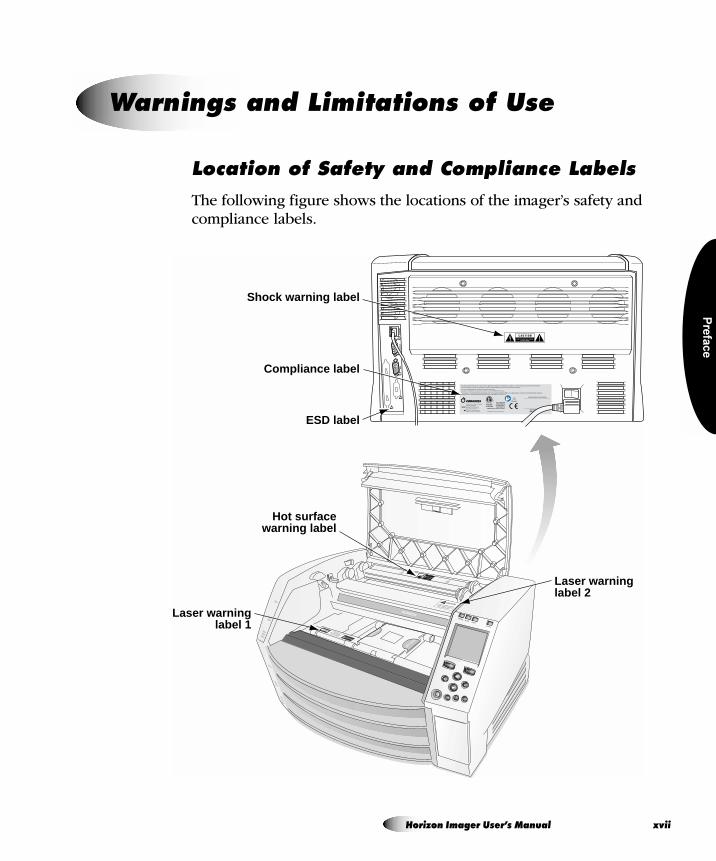
içÅ~íáçå=çÑ=p~ÑÉíó=~åÇ=`çãéäá~åÅÉ=i~ÄÉäë
The following figure shows the locations of the imager’s safety and compliance labels.
t~êåáåÖë=~åÇ=iáãáí~íáçåë=çÑ=rëÉ
NETW
ORK
CONS
OLE
UPS
AVOID EXPOSURE
LASER RADIATION IS EMITTED
FROM THIS APERTURE !
CLASS 2 LASER RADIATION WHEN
OPEN AND INTERLOCKS DEFEATEDDO NOT STARE INTO BEAM
Shock warning label
Compliance label
ESD label
Hot surfacewarning label
Laser warninglabel 1
Laser warninglabel 2
Horizon Imager User’s Manual xvii
xvi
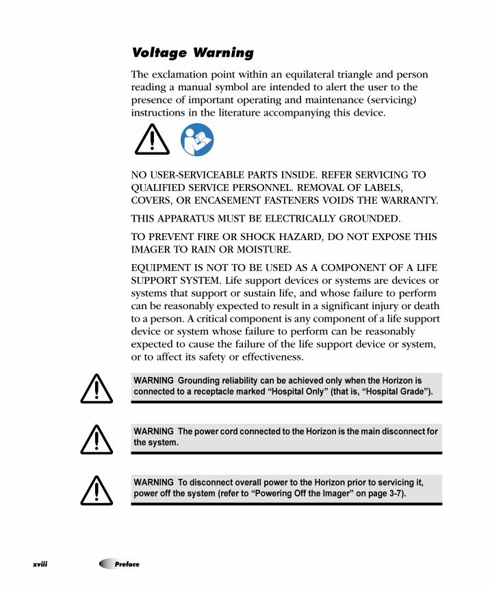
sçäí~ÖÉ=t~êåáåÖ
The exclamation point within an equilateral triangle and person reading a manual symbol are intended to alert the user to the presence of important operating and maintenance (servicing) instructions in the literature accompanying this device.
NO USER-SERVICEABLE PARTS INSIDE. REFER SERVICING TO QUALIFIED SERVICE PERSONNEL. REMOVAL OF LABELS, COVERS, OR ENCASEMENT FASTENERS VOIDS THE WARRANTY.
THIS APPARATUS MUST BE ELECTRICALLY GROUNDED.
TO PREVENT FIRE OR SHOCK HAZARD, DO NOT EXPOSE THIS IMAGER TO RAIN OR MOISTURE.
EQUIPMENT IS NOT TO BE USED AS A COMPONENT OF A LIFE SUPPORT SYSTEM. Life support devices or systems are devices or systems that support or sustain life, and whose failure to perform can be reasonably expected to result in a significant injury or death to a person. A critical component is any component of a life support device or system whose failure to perform can be reasonably expected to cause the failure of the life support device or system, or to affect its safety or effectiveness.
WARNING Grounding reliability can be achieved only when the Horizon is
connected to a receptacle marked “Hospital Only” (that is, “Hospital Grade”).
WARNING The power cord connected to the Horizon is the main disconnect for
the system.
WARNING To disconnect overall power to the Horizon prior to servicing it,
power off the system (refer to “Powering Off the Imager” on page 3-7).
ii Preface
Pre
fac
e
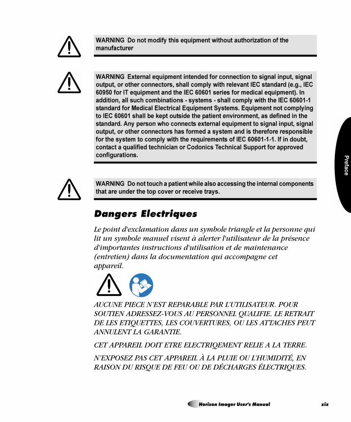
a~åÖÉêë=bäÉÅíêáèìÉë
Le point d'exclamation dans un symbole triangle et la personne qui lit un symbole manuel visent à alerter l'utilisateur de la présence d'importantes instructions d'utilisation et de maintenance (entretien) dans la documentation qui accompagne cet appareil.
AUCUNE PIECE N’EST REPARABLE PAR L’UTILISATEUR. POUR SOUTIEN ADRESSEZ-VOUS AU PERSONNEL QUALIFIE. LE RETRAIT DE LES ETIQUETTES, LES COUVERTURES, OU LES ATTACHES PEUT ANNULENT LA GARANTIE.
CET APPAREIL DOIT ETRE ELECTRIQEMENT RELIE A LA TERRE.
N’EXPOSEZ PAS CET APPAREIL À LA PLUIE OU L’HUMIDITÉ, EN RAISON DU RISQUE DE FEU OU DE DÉCHARGES ÉLECTRIQUES.
WARNING Do not modify this equipment without authorization of the
manufacturer
WARNING External equipment intended for connection to signal input, signal
output, or other connectors, shall comply with relevant IEC standard (e.g., IEC
60950 for IT equipment and the IEC 60601 series for medical equipment). In
addition, all such combinations - systems - shall comply with the IEC 60601-1
standard for Medical Electrical Equipment Systems. Equipment not complying
to IEC 60601 shall be kept outside the patient environment, as defined in the
standard. Any person who connects external equipment to signal input, signal
output, or other connectors has formed a system and is therefore responsible
for the system to comply with the requirements of IEC 60601-1-1. If in doubt,
contact a qualified technician or Codonics Technical Support for approved
configurations.
WARNING Do not touch a patient while also accessing the internal components
that are under the top cover or receive trays.
Horizon Imager User’s Manual xix
xx
CET APPAREIL NE DOIT PAS ÊTRE UTILISÉ COMME COMPOSANT D’UN SYSTÈME D’ASSISTANCE VITALE. Les devis ou les systèmes vitale sont quelque devis ou système qui assistent ou soutiennent la vie, et si les devis ou systèmes échouent, on peut attend raisonnablement la mort ou la blessure. Cet appareil ne doit pas être utilisé dans des conditions où la défaillance de l’appareil pourrait entrainer la blessure ou la mort de quelqu’un.
ATTENTION Une mise à la terre fiable est possible seulement pendant que le
Horizon est connecté aux appareils marqué "Hospital Only" (de qualité
hositalière).
ATTENTION Le fil électrique connecté à le Horizon est le système de coupure
principal de l’appareil.
ATTENTION Pour débrancher le fil électrique avant le soutien, se déconnecter
et puis éteint le système (renvoyer à " Powering Off the Imager " sur la
page 3-7).
ATTENTION Ne modifiez pas cet équipement sans l'autorisation du fabricant.
ATTENTION Toute équipement externe qui serait connecté vers le signal
d'entrée ou de sortie ou autre connecteur, doit être compatible avec la norme
IEC standard (IEC 60950 pour les équipements IT et IEC 60601 pour les
équipements médicaux). Toutes les combinaisons de systèmes doivent être
compatible avec IEC60601-1 standard, sécurité requise pour les équipements
électriques médicaux. Tout équipement non compatible avec IEC 60601 doit
être mis a l'écart de l'environnement patient, comme définis dans le standard.
Toute personne qui connecte un équipement externe vers une entrée signal, ou
sortie signal ou autres connecteur, est responsable de la compatibilité avec IEC
60601-1-1. Si vous avez un doute, contactez un technicien qualifié ou le support
technique de Codonics pour l'approbation des configurations.
ATTENTION Ne pas touchez un patient lors d'un accès aux composants
internes qui sont sous le capot supérieur ou les bacs de sortie.
Preface
Pre
fac
e
i~ëÉê=t~êåáåÖ
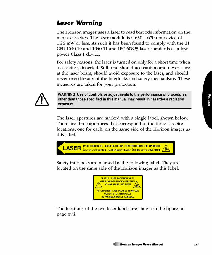
The Horizon imager uses a laser to read barcode information on the media cassettes. The laser module is a 650 – 670-nm device of 1.26 mW or less. As such it has been found to comply with the 21 CFR 1040.10 and 1040.11 and IEC 60825 laser standards as a low power Class 1 device.
For safety reasons, the laser is turned on only for a short time when a cassette is inserted. Still, one should use caution and never stare at the laser beam, should avoid exposure to the laser, and should never override any of the interlocks and safety mechanisms. These measures are taken for your protection.
The laser apertures are marked with a single label, shown below. There are three apertures that correspond to the three cassette locations, one for each, on the same side of the Horizon imager as this label.
Safety interlocks are marked by the following label. They are located on the same side of the Horizon imager as this label.
The locations of the two laser labels are shown in the figure on page xvii.
WARNING Use of controls or adjustments to the performance of procedures
other than those specified in this manual may result in hazardous radiation
exposure.
Horizon Imager User’s Manual xxi
xx
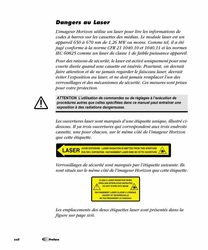
a~åÖÉêë=~ì=i~ëÉê
L’imageur Horizon utilise un laser pour lire les informations de codes à barres sur les cassettes des médias. Le module laser est un appareil 650 à 670 nm de 1,26 MW ou moins. Comme tel, il a été jugé conforme à la norme CFR 21 1040.10 et 1040.11 et les normes IEC 60825 comme un laser de classe 1 de faible puissance appareil.
Pour des raisons de sécurité, le laser est activé uniquement pour une courte durée quand une cassette est insérée. Pourtant, on devrait faire attention et de ne jamais regarder le faisceau laser, devrait éviter l’exposition au laser, et ne doit jamais remplacer l’un des verrouillages et des mécanismes de sécurité. Ces mesures sont prises pour votre protection.
Les ouvertures laser sont marqués d’une étiquette unique, illustré ci-dessous. Il ya trois ouvertures qui correspondent aux trois endroits cassette, une pour chacun, sur le même côté de l’imageur Horizon que cette étiquette.
Verrouillages de sécurité sont marqués par l’étiquette suivante. Ils sont situés sur le même côté de l’imageur Horizon que cette étiquette.
Les emplacements des deux étiquettes laser sont présentés dans la figure sur page xvii.
ATTENTION L’utilisation de commandes ou de réglages à l’exécution de
procédures autres que celles spécifiées dans ce manuel peut entraîner une
exposition à des radiations dangereuses.
ii Preface
Pre
fac
e
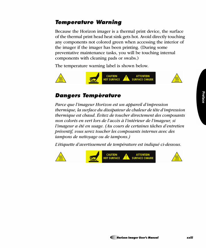
qÉãéÉê~íìêÉ=t~êåáåÖ
Because the Horizon imager is a thermal print device, the surface of the thermal print head heat sink gets hot. Avoid directly touching any components not colored green when accessing the interior of the imager if the imager has been printing. (During some preventative maintenance tasks, you will be touching internal components with cleaning pads or swabs.)
The temperature warning label is shown below.
a~åÖÉêë=qÉãé¨ê~íìêÉ
Parce que l’imageur Horizon est un appareil d’impression thermique, la surface du dissipateur de chaleur de tête d’impression thermique est chaud. Évitez de toucher directement des composants non colorés en vert lors de l’accès à l’intérieur de l’imageur, si l’imageur a été en usage. (Au cours de certaines tâches d’entretien préventif, vous serez toucher les composants internes avec des tampons de nettoyage ou de tampons.)
L’étiquette d’avertissement de température est indiqué ci-dessous.
CAUTIONHOT SURFACE
ATTENTIONSURFACE CHAUDE
CAUTIONHOT SURFACE
ATTENTIONSURFACE CHAUDE
Horizon Imager User’s Manual xxiii
xx
`çãéäá~åÅÉ
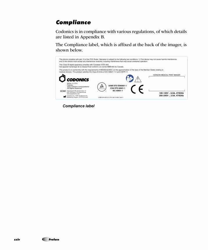
Codonics is in compliance with various regulations, of which details are listed in Appendix B.
The Compliance label, which is affixed at the back of the imager, is shown below.
Compliance label
iv Preface
Pre
fac
e
pÉêá~ä=kìãÄÉêI=`çåÑáÖìê~íáçåI=a~íÉ=`çÇÉI=~åÇ=jçÇáÑáÅ~íáçå=`çÇÉë
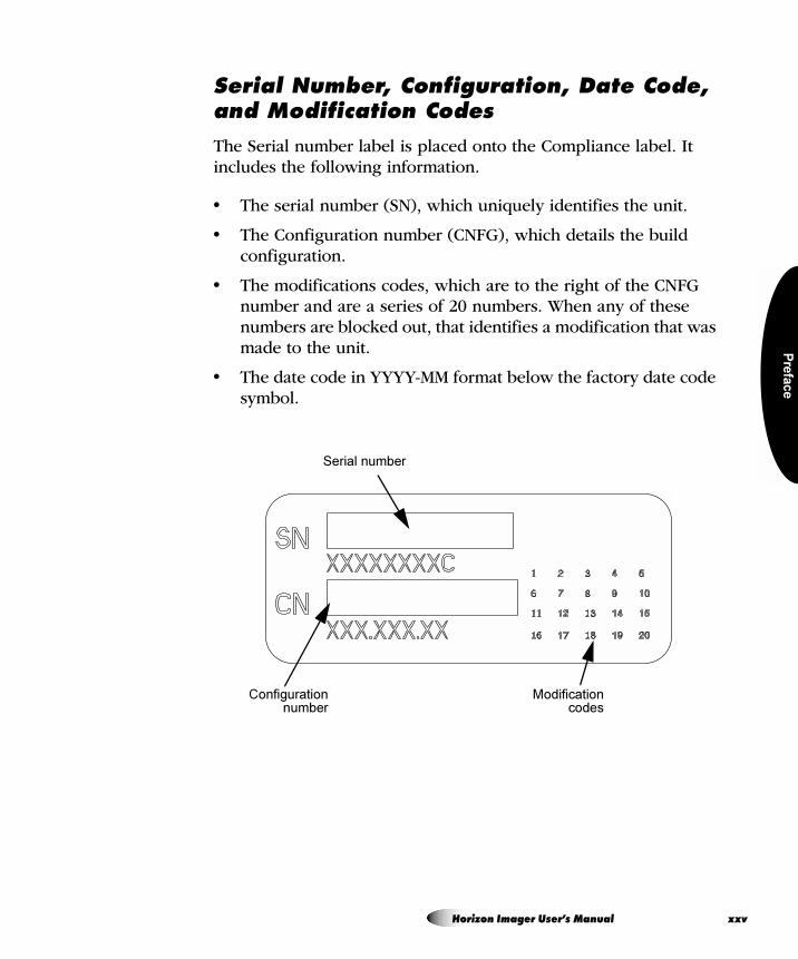
The Serial number label is placed onto the Compliance label. It includes the following information.
• The serial number (SN), which uniquely identifies the unit.
• The Configuration number (CNFG), which details the build configuration.
• The modifications codes, which are to the right of the CNFG number and are a series of 20 numbers. When any of these numbers are blocked out, that identifies a modification that was made to the unit.
• The date code in YYYY-MM format below the factory date code symbol.
Serial number
Configurationnumber
Modificationcodes
Horizon Imager User’s Manual xxv
xx
bpa=`~ìíáçå
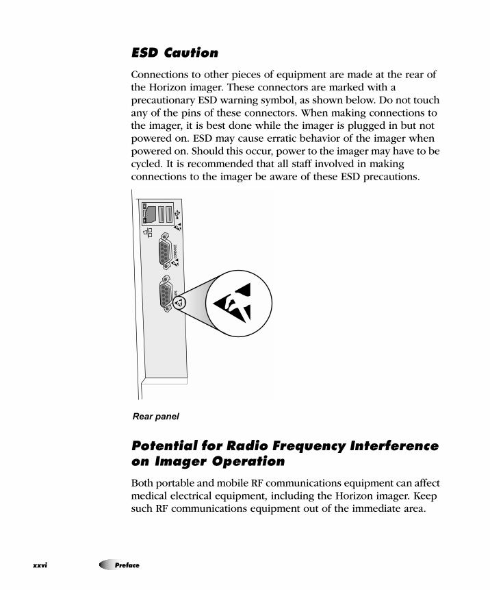
Connections to other pieces of equipment are made at the rear of the Horizon imager. These connectors are marked with a precautionary ESD warning symbol, as shown below. Do not touch any of the pins of these connectors. When making connections to the imager, it is best done while the imager is plugged in but not powered on. ESD may cause erratic behavior of the imager when powered on. Should this occur, power to the imager may have to be cycled. It is recommended that all staff involved in making connections to the imager be aware of these ESD precautions.
Rear panel
mçíÉåíá~ä=Ñçê=o~Çáç=cêÉèìÉåÅó=fåíÉêÑÉêÉåÅÉ=çå=fã~ÖÉê=léÉê~íáçå
Both portable and mobile RF communications equipment can affect medical electrical equipment, including the Horizon imager. Keep such RF communications equipment out of the immediate area.
CONS
OLE
UPS
vi Preface
Pre
fac
e
mçíÉåíá~ä=Ñçê=o~Çáç=~åÇ=qÉäÉîáëáçå=fåíÉêÑÉêÉåÅÉ
The Horizon imager generates and uses radio frequency energy, and if not installed and used properly, that is, in strict accordance with the manufacturer’s instructions, may cause interference to radio and television reception. It has been type tested and found to comply with Class B emission limits for a computing device in accordance with the specifications in Subpart J of Part 15 of FCC Rules, which are designed to provide reasonable protection against such interference when operating in a commercial environment. Operation of the equipment in a residential area is likely to cause interference, in which case the user, at his own expense, will be required to take whatever measures may be appropriate to correct the interference. If your imager does cause interference to radio or television reception, you are encouraged to try to correct the interference by one or more of the following measures:
• Reorient the receiving antenna
• Relocate the imager with respect to the receiver
If necessary, you should consult Codonics technical support or an experienced radio/television technician for additional suggestions. You may find the following booklet prepared by the Federal Communications Commission helpful: How to Identify and Resolve Radio-TV Interference Problems. This booklet is available from the U.S. Government Printing Office, Washington, D.C. 20402, Stock No. 004-000-00345-4.
Le présent appareil numérique n’émet pas de bruits radio-électriques dépassant les limites applicables aux appareils numériques de la Classe B prescrites dans le Réglement sur le brouillage radioélectrique édicté par le ministére des Communications du Canada.
Horizon Imager User’s Manual xxvii
xx
This product is in conformity with the requirements of EC Council directive MDD93/42/EEC on the approximation of the laws of the Member States relating to medical devices. This product satisfies the Class B limits of IEC60601-1-2 and CISPR 11. A declaration of conformity with the requirements of the Directive has been signed by the Director of Operations. Horizon is approved for export via FDA Certificates to Foreign Government and registered as a medical device for import. A current list of countries is available on request.
dìáÇ~åÅÉ=oÉÖ~êÇáåÖ=bäÉÅíêçã~ÖåÉíáÅ=bãáëëáçåë=~åÇ=fããìåáíó
Suitable Environments:
• Horizon is intended for use in professional healthcare facility environments, including hospitals and medical clinics.
• Horizon has not been evaluated for use near HF surgical equipment. If use near HF surgical equipment is desired, the user is responsible for verifying proper operation of the Horizon. If Horizon does not perform correctly in this environment, move the Horizon farther from the source of the electromagnetic disturbance.
• Horizon has not been evaluated for use in emergency medical vehicles.
As a support device, Horizon does not provide essential performance.
WARNING Use of this equipment adjacent to or stacked with other equipment
should be avoided because it could result in improper operation. If such use is
necessary, this equipment and the other equipment should be observed to
verify that they are operating normally.
viii Preface
Pre
fac
e
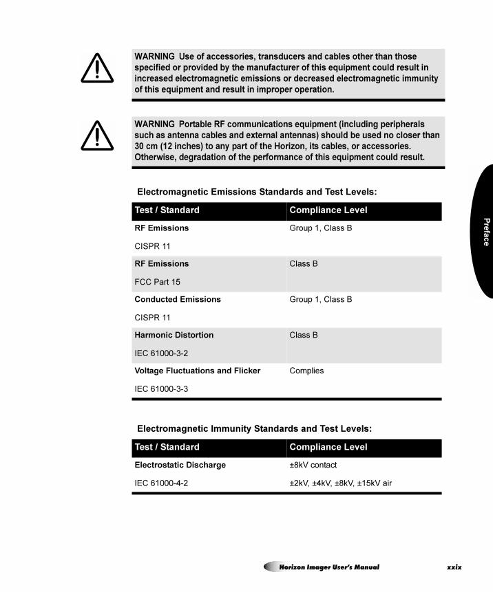
WARNING Use of accessories, transducers and cables other than those
specified or provided by the manufacturer of this equipment could result in
increased electromagnetic emissions or decreased electromagnetic immunity
of this equipment and result in improper operation.
WARNING Portable RF communications equipment (including peripherals
such as antenna cables and external antennas) should be used no closer than
30 cm (12 inches) to any part of the Horizon, its cables, or accessories.
Otherwise, degradation of the performance of this equipment could result.
Electromagnetic Emissions Standards and Test Levels:
Test / Standard Compliance Level
RF Emissions
CISPR 11
Group 1, Class B
RF Emissions
FCC Part 15
Class B
Conducted Emissions
CISPR 11
Group 1, Class B
Harmonic Distortion
IEC 61000-3-2
Class B
Voltage Fluctuations and Flicker
IEC 61000-3-3
Complies
Electromagnetic Immunity Standards and Test Levels:
Test / Standard Compliance Level
Electrostatic Discharge
IEC 61000-4-2
±8kV contact
±2kV, ±4kV, ±8kV, ±15kV air
Horizon Imager User’s Manual xxix
xx
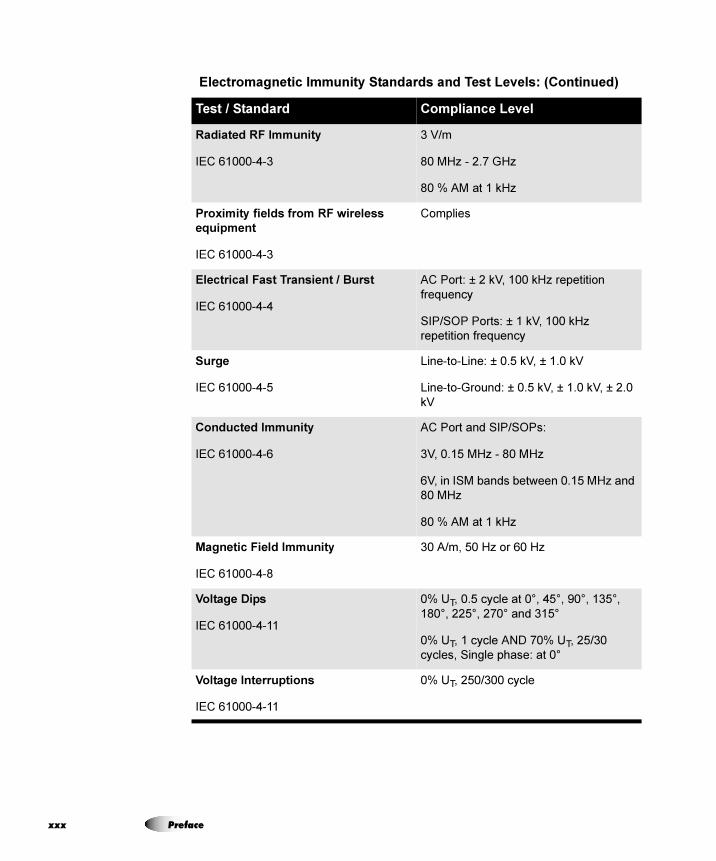
Radiated RF Immunity
IEC 61000-4-3
3 V/m
80 MHz - 2.7 GHz
80 % AM at 1 kHz
Proximity fields from RF wireless
equipment
IEC 61000-4-3
Complies
Electrical Fast Transient / Burst
IEC 61000-4-4
AC Port: ± 2 kV, 100 kHz repetition
frequency
SIP/SOP Ports: ± 1 kV, 100 kHz
repetition frequency
Surge
IEC 61000-4-5
Line-to-Line: ± 0.5 kV, ± 1.0 kV
Line-to-Ground: ± 0.5 kV, ± 1.0 kV, ± 2.0
kV
Conducted Immunity
IEC 61000-4-6
AC Port and SIP/SOPs:
3V, 0.15 MHz - 80 MHz
6V, in ISM bands between 0.15 MHz and
80 MHz
80 % AM at 1 kHz
Magnetic Field Immunity
IEC 61000-4-8
30 A/m, 50 Hz or 60 Hz
Voltage Dips
IEC 61000-4-11
0% UT, 0.5 cycle at 0°, 45°, 90°, 135°,
180°, 225°, 270° and 315°
0% UT, 1 cycle AND 70% UT, 25/30
cycles, Single phase: at 0°
Voltage Interruptions
IEC 61000-4-11
0% UT, 250/300 cycle
Electromagnetic Immunity Standards and Test Levels: (Continued)
Test / Standard Compliance Level
x Preface
Pre
fac
e
p~ÑÉíó=mêÉÅ~ìíáçåë
• Never connect this imager to any outlet or power supply that has a voltage or frequency different than that specified on the rear of the imager.
• When servicing the imager, always power it off using the (power) key at the control panel, then turn the rocker switch
in the back to the 0 (off) position, then unplug the imager.
• Damage to the power cord may cause fire or shock hazard. When unplugging the power cord, hold it by the plug only and remove the plug carefully.
• If the power cord needs to be replaced, replace it only with another Codonics power cord manufactured specifically for your imager’s power configuration.
• If the imager is smoking or making unusual sounds, power off and unplug the imager immediately.
• Do not insert foreign objects of any kind into the imager; doing so can constitute a safety hazard and cause extensive damage.
• Do not place any liquid containers on the imager. If, for some reason, liquid seeps into the imager, power off the imager and unplug the power cord from the source outlet. If used without corrective measures, the imager may be damaged.
• Do not use the imager near flammable gases.
Horizon Imager User’s Manual xxxi
xx
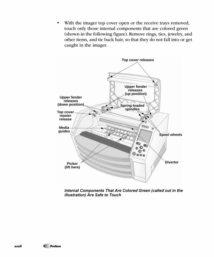
• With the imager top cover open or the receive trays removed, touch only those internal components that are colored green (shown in the following figure). Remove rings, ties, jewelry, and other items, and tie back hair, so that they do not fall into or get caught in the imager.
Internal Components That Are Colored Green (called out in the illustration) Are Safe to Touch
Upper fenderreleases
(up position)
Top cover releases
Spring-loadedspindles
Spool wheels
Upper fenderreleases
(down position)
Top covermasterrelease
Mediaguides
Picker (lift here)
Diverter
xii Preface
Pre
fac
e
mê¨Å~ìíáçå=ÇÛbãéäçá
• Ne connectez jamais cet imageur à une prise ou d’alimentation qui a une tension ou une fréquence différente de celle indiquée à l’arrière de l’imageur.
• Lors de l’entretien de l’imageur, toujours l’éteindre à l’aide de la touche (power) à partir du panneau de contrôle, puis tournez le commutateur à bascule à l’arrière pour le 0 (off), puis débranchez l’imageur.
• D’endommager le cordon d’alimentation peut provoquer un incendie ou d’électrocution. Lorsque vous débranchez le cordon d’alimentation, tenez-le par la fiche et retirez le bouchon avec précaution.
• Si le cordon d’alimentation doit être remplacé, il ne remplacer que par une autre cordon d’alimentation Codonics fabriqués spécialement pour la configuration de la puissance de votre imageur.
• Si l’imageur est fumeur ou en faisant des sons inhabituels, éteignez et débranchez l’imageur immédiatement.
• Ne pas insérer d’objets étrangers dans l’imageur; cela peut constituer un danger pour la sécurité et de causer des dommages importants.
• Ne pas placer de récipients de liquide sur l’imageur. Si, pour quelque raison, liquide pénètre dans l’imageur, éteignez l’imageur et débranchez le cordon d’alimentation de la prise source. S’il est utilisé sans mesures correctives, l’imageur peut être endommagé.
• Ne pas utiliser l’imageur à proximité de gaz inflammables.
Horizon Imager User’s Manual xxxiii
xx
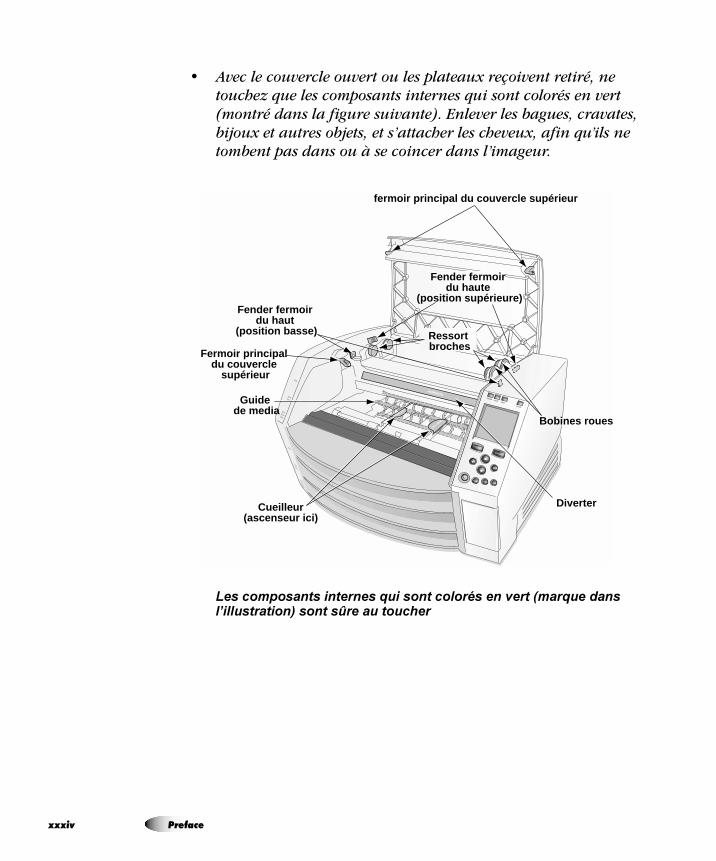
• Avec le couvercle ouvert ou les plateaux reçoivent retiré, ne touchez que les composants internes qui sont colorés en vert (montré dans la figure suivante). Enlever les bagues, cravates, bijoux et autres objets, et s’attacher les cheveux, afin qu’ils ne tombent pas dans ou à se coincer dans l’imageur.
Les composants internes qui sont colorés en vert (marque dans l’illustration) sont sûre au toucher
Fender fermoir du haute
(position supérieure)
fermoir principal du couvercle supérieur
Ressort broches
Bobines roues
Fender fermoir du haut
(position basse)
Fermoir principal du couvercle
supérieur
Guide de media
Cueilleur(ascenseur ici)
Diverter
xiv Preface
Pre
fac
e
içÅ~íáçå=mêÉÅ~ìíáçåë
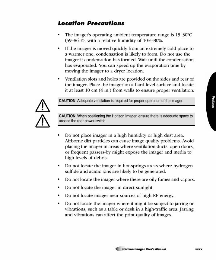
• The imager’s operating ambient temperature range is 15–30ºC (59–86ºF), with a relative humidity of 10%–80%.
• If the imager is moved quickly from an extremely cold place to a warmer one, condensation is likely to form. Do not use the imager if condensation has formed. Wait until the condensation has evaporated. You can speed up the evaporation time by moving the imager to a dryer location.
• Ventilation slots and holes are provided on the sides and rear of the imager. Place the imager on a hard level surface and locate it at least 10 cm (4 in.) from walls to ensure proper ventilation.
• Do not place imager in a high humidity or high dust area. Airborne dirt particles can cause image quality problems. Avoid placing the imager in areas where ventilation ducts, open doors, or frequent passers-by might expose the imager and media to high levels of debris.
• Do not locate the imager in hot-springs areas where hydrogen sulfide and acidic ions are likely to be generated.
• Do not locate the imager where there are oily fumes and vapors.
• Do not locate the imager in direct sunlight.
• Do not locate imager near sources of high RF energy.
• Do not locate the imager where it might be subject to jarring or vibrations, such as a table or desk in a high-traffic area. Jarring and vibrations can affect the print quality of images.
CAUTION Adequate ventilation is required for proper operation of the imager.
CAUTION When positioning the Horizon Imager, ensure there is adequate space to
access the rear power switch.
Horizon Imager User’s Manual xxxv
xx
• Horizon satisfies the electrical safety limits of IEC60601-1 and CISPR 11 and is suitable for patient care area location. Check with local ordinances and installation guidelines to confirm approved location requirements.
båîáêçååÉãÉåí=ÇÉ=cçåÅíáçååÉãÉåí
• Les conditions normales d’utilisation de l’appareil sont : une température de 15 à 30ºC et une humidité relative de 20 % à 80 %.
• En cas de variation rapide de la température, de la condensation peut se former. En ce cas la n’utilisez pas l’appareil, attendez que la condensation se soit évaporée. Vous pouvez accélère cette évaporation en déplacent l’appareil dans un endroit sec.
• Fentes de ventilation et les trous sont prévus sur les côtés et l’arrière de l’imageur. Placez l’imageur sur une surface plane et dure et de le localiser au moins 10 cm (4 po) du mur pour assurer une bonne ventilation.
• Toujours placez l’appareil dans une zone propre et non-humide. Des particules de poussières peuvent causer des disfonctionnements de la qualité d’imprimante. Évitez de placer l’appareil à proximité d’une bouche de ventilation, d’une porte, ou d’un endroit très fréquenté car cela pourrait exposer l’appareil ainsi que les étiquettes à la poussière.
• Ne placez pas l’appareil à proximité d’une source de chaleur ou de substances acides.
ATTENTION Une ventilation adéquate est nécessaire pour le bon fonctionnement de
l’imageur.
ATTENTION Lors du positionnement de l'imageur Horizon, laisser un espace
adequate pour accéder à l'interrupteur d'alimentation à l'arrière.
xvi Preface
Pre
fac
e
• Ne placez pas l’appareil dans une endroit où il y a des vapeurs huileuses et grasses.
• N’exposez pas l’appareil à la lumière directe du soleil.
• Ne placez pas l’appareil près d’une source haute fréquence.
• Ne placez pas l’appareil dans un lieu où il pourrait être exposé à des vibrations, car cela peut nuire l’impression des média.
• Horizon satisfait aux limites de sécurité électrique de la norme IEC60601-1 et CISPR 11 et est adapté à l’emplacement des soins du patient. Vérifiez avec les ordonnances locales et les directives d’installation pour confirmer les exigences endroit approuvé.
`äÉ~åáåÖ=mêÉÅ~ìíáçåë
• Many plastic components are used in the imager’s construction. Coat flecking and deformation is likely to occur if the imager is wiped with chemical dusters, benzene, thinners, insecticides, or other solvents. Rubber and PVC materials left in contact with the imager for extended times will cause damage. Never use petroleum-based solutions or abrasive cleaners.
• To clean the imager cover, first power off the imager using the (power) key at the control panel, then turn the rocker switch
in the back to the 0 (off) position, then unplug the imager. Clean the cover with a soft cloth slightly moistened with a mild soap and water solution. Allow the cover to completely dry before operating the imager again.
Horizon Imager User’s Manual xxxvii
xx
mê¨Å~ìíáçåë=ÇÛbåíêÉíáÉå
• Il y a beaucoup des choses plastiques utilisant avec la fabrication de l’imageur. L’emploi des chiffons chimiques, de benzène, des diluants, des insecticides, ou des autres solvants peuvent causer les dommages à l’extérieur ou les déformations. Le caoutchouc ou le PVC qui ont beaucoup de contact avec l’imageur causeront les dommages. N’utilisez jamais les nettoyeuses avec pétrole ou les nettoyeuses abrasives.
• Pour nettoyer la couverture d’imageur, première éteignant l’imageur en utilisant la touche (alimentation) au panneau de contrôle, puis tournez l’interrupteur à bascule à l’arrière au 0 (OFF) position, puis débranchez l’imageur. Nettoyez le couvercle avec un chiffon doux légèrement humidifié avec une solution de savon doux et d’eau. Laisser la couverture de sécher complètement avant d’utiliser l’imageur à nouveau.
jÉÇá~
• For ChromaVista® color prints, the consumed ribbon contains facsimiles of any patient images printed to ChromaVista color sheets. Therefore, you must properly dispose of or destroy consumed ribbon to ensure the confidentiality of patient images.
• The optical density of reflective and transmissive prints have a nominal range of: Dmin = 0.10 OD (reflective), 0.11 OD (transmissive) to Dmax = 2.10 OD (reflective), 3.1 OD (transmissive). Actual optical densities may vary based on media variations and on the instrument being used to measure density.
For example, DirectVista® Clear film may have a lower Dmin and Dmax than DirectVista Blue film.
xviii Preface
Pre
fac
e
• The Horizon imager includes a built-in densitometer. The built-in densitometer is designed to produce consistent prints by compensating for variation from one film cassette to another and one imager to another. For applications that require absolute control of the maximum density, the results should be checked against a bench-top commercial densitometer. The internal densitometer can be calibrated to a desktop unit. See the Horizon Imager Technical Manual for more information.
• DirectVista media is optimized for grayscale prints, while ChromaVista is optimized for color prints. If ChromaVista is not giving you satisfactory results with grayscale images, you may want to consider using DirectVista media for those applications.
• Media variations between different production lots may produce subtle differences in image quality and color. These variations most often occur in color ribbons and are characterized as a slight color hue in grayscale images.
• Codonics film media is designed to be viewed using a light box suitable for viewing medical diagnostic images.
• Codonics paper/white film media is designed to be viewed under cool-white, fluorescent light. Spectral differences and intensity variations in the viewing light sources can change the apparent color of images printed on paper/white film.
• Printed images that are subject to prolonged exposure to sunlight, ultraviolet light, or extreme heat may degrade in image quality. (For example, printed sheets should not be stored in an automobile on a sunny day.) Precautions should be used to avoid prolonged direct exposure.
`çÇçåáÅë=m~éÉêLtÜáíÉ=cáäã=jÉÇá~
The terms “white paper” and “white film” are synonymous references and used interchangeably in this manual.
Horizon Imager User’s Manual xxxix
xl
cáäÉ=qê~åëÑÉê=îá~=cqm=~åÇ=imo
• Different users who share a user name when transferring files to the imager may cause unpredictable and erroneous printed output. The imager associates information with the user name. Each user should have a unique user name when connecting to the imager via FTP and LPR.
`çäçê=j~å~ÖÉãÉåí
• Image settings—including gamma, contrast, Dmax, saturation, and MCM™ (Medical Color Matching™)—are intended to compensate for differences that may occur between image acquisition and image printing. These filters allow you to accurately render the final printed image. You should use care when applying these filters to avoid over compensation.
• The Default User Settings set at the control panel will potentially affect prints made by all users. Use caution when changing the default settings.
Preface
Pre
fac
e
fã~ÖÉ=pÅ~äáåÖ
• Scaling an image will filter the original image data and add or remove information, which may affect the accuracy of the final printed image. The amount of information added or removed will also vary with the magnitude of the scale factor applied. This can also affect the accuracy of the final printed image. You should be aware of the properties and limitations of each scaling algorithm and select the appropriate algorithm for the task.
e~êÇï~êÉ=s~êá~íáçåë
• Components used in the imager may vary, causing differences in image quality. The thermal process of producing a print utilizes many components that are calibrated to provide consistency between imagers. There are subtle differences between imagers that can cause print variations. These differences usually apply to thermal print head calibration. Other factors such as age, usage, heat, mechanical wear, and shipping can affect image color and quality.
• The type of media used to install software updates and to backup imager configuration settings depends on hardware variations. If the imager has a built-in Zip drive, installations and backups are performed using 100-MB Zip disks. If the imager does not have a built-in Zip drive, USB flash drives are used with the USB ports on the rear panel. Throughout this manual, Zip disks and USB flash drives are referred to as installation media or backup media, depending on the operation being performed.
NOTE: If the imager has both a ZIP drive and a USB port, always use the ZIP disk to install
software and save configuration settings.3
Horizon Imager User’s Manual xli

xli
Disposal of this product and consumables shall be in accordance with all applicable laws and regulations in effect at the locality at the time of disposal.
Conditions et Règles d’Utilisation
L’utilisation de ce produit doit être conforme à toutes les lois et règlements applicables sur le lieu d’utilisation.
European Disposal Requirements
Codonics imagers and electronic accessory devices are not to be discarded or recycled; rather they are to be returned to the manufacturer. Contact Codonics directly or by the link provided for the latest information concerning:
• Identification of the country-specific Importer/Distributor/Producer
• Product return and treatment of our electronic products
Manufacturer: Codonics Inc.17991 Englewood DriveMiddleburg Heights, OH 44130 USAPhone: +1.440.243.1198Fax: +1.440.243.1334E-mail: [email protected]
aáëéçë~ä=oÉèìáêÉãÉåíë
i Preface
Pre
fac
e
Codonics electronic products and accessories bearing the following symbol are subject to European Directive on Waste Electrical and Electronic Equipment (WEEE) 2002/96/EC, amended by Directive 2003/108/EC. The EN 50419 symbol indicates separate collection and return required.
EN 50419 symbol
The intended use of the Horizon Series Imagers is high-resolution hardcopy imaging of digital image source material and through the conversion of electronic signals from a wide variety of direct/indirect medical imaging modality outputs. The hardcopy output includes, however is not limited to, digital radiography, nuclear medicine, ultrasound, CT, MRI, CR, and Radiation Therapy planning. Images are suitable for medical image diagnosis use and referral. The system is intended for use by medical radiologists, imaging modality specialists, and communications to referring physicians.
The Horizon Series Imagers are dry, thermal, grayscale (G, GS,GS-s,GS-Rad, G1, and G2 models) and grayscale/color (Ci, Ci-s, Ci-RAD, and SF models) direct thermal printer/imagers.
fåÇáÅ~íáçåë=Ñçê=rëÉ
CAUTION Approved FDA Class 2 device - Federal law restricts this device to be sold
for use by or on the order of a physician.
Horizon Imager User’s Manual xliii
xli
The Horizon XL is a special model adding 14 x 36-in. and 14 x 51-in. true size “long” media that permits digital direct orthopaedic application hardcopy, including diagnosis and analysis of scoliosis, weight bearing spine/hip/knee, and long bone/hip prosthetic and orthopedic appliances work-up and surgical planning. Horizon XL is applicable to true-size hardcopy of whole body CT, MRI, and Angiographic and Venous flow imaging procedures.
Horizon Imagers are 510(k) cleared to market as FDA Class 2 devices, Regulation number 892.2040, Classification Product Code LMC: Horizon Series Medical Multimedia Dry Imagers K021054 and Horizon XL Medical Long Film Imager Hardcopy Multimedia K060440.
v Preface
Intro
du
ctio
n
= NfåíêçÇìÅíáçå
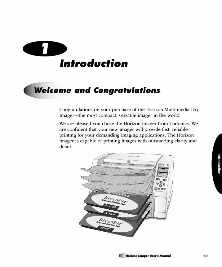
Congratulations on your purchase of the Horizon Multi-media Dry Imager—the most compact, versatile imager in the world!
We are pleased you chose the Horizon imager from Codonics. We are confident that your new imager will provide fast, reliable printing for your demanding imaging applications. The Horizon imager is capable of printing images with outstanding clarity and detail.
tÉäÅçãÉ=~åÇ=`çåÖê~íìä~íáçåë
Horizon Imager User’s Manual 1-1
1-2
Note that there are several models of the Horizon imager, each with different features. This manual describes all of the available features, so some may not apply to your model.
pí~íÉJçÑJíÜÉJ^êí=mêáåíáåÖ=qÉÅÜåçäçÖó
Codonics DirectVista grayscale paper/white film and film, and ChromaVista paper/white film, are state-of-the-art imaging media that are ideally suited to CT (computed tomography), MRI (magnetic resonance imaging), digital radiography, fluoroscopy, PACS (picture archiving and communication system), ultrasound, nuclear medicine, portable X-ray, mammography, dental, and other imaging applications.
DirectVista grayscale direct thermal technology produces stunning, diagnostic-quality grayscale prints without the need for chemicals or ribbons.
The unique ChromaVista color dye-diffusion process transfers dyes from a multi-patch color ribbon onto specially coated paper/white film. Different levels of heat are used to regulate how much dye is transferred. The paper/white film is precisely registered in the imager so that it stays aligned during each pass, resulting in diagnostic-quality color prints. As an added benefit, you do not have to remove the color ribbon when printing to DirectVista grayscale media.
pã~ää=cççíéêáåí
The small footprint of the Horizon imager makes it ideal for desktop applications, allowing it to be located close to a user’s workspace. Its size and weight also make the imager ideal for mobile applications.
fã~ÖÉê=cÉ~íìêÉë
Introduction
Intro
du
ctio
n
táÇÉ=s~êáÉíó=çÑ=jÉÇá~=qóéÉë=~åÇ=páòÉë
The Horizon imager supports output to paper/white film and film media in a wide variety of sizes. For a complete list, refer to “Ordering Media” on page 4-12.
b~ëó=^ÅÅÉëë=Ñêçã=~=s~êáÉíó=çÑ=fã~ÖÉ=pçìêÅÉë
The Horizon imager can print extraordinary images from a variety of image sources, including:
• DICOM Print Service Class-compliant image capture or viewing applications. This option is explained in Chapter 5.
• Windows and Macintosh applications via PostScript. This option is explained in Chapter 6.
• FTP and LPR. Support for these sources comes standard with the imager. FTP and LPR are considered advanced printing methods, typically used by system integrators and only with UNIX applications. Basic procedures for printing via FTP and LPR are provided in Chapter 7. They are fully explained in the Horizon Imager Technical Manual.
• Backup media (either a 100-MB Zip disk or a USB flash drive). This option is explained in the Horizon Imager Technical Manual.
• Codonics SA-2000 Analog Framegrabber. Instructions for using the SA-2000 are explained in the SA-2000 Operator Manual.
Via its TCP/IP–Ethernet connection, the Horizon imager can support printing requests coming simultaneously from multiple devices on the network:
• DICOM (up to 12 simultaneous connections)
• DICOM Lite (1 or 2 simultaneous connections)
• PostScript (up to 11 simultaneous connections)
Horizon Imager User’s Manual 1-3
1-4
• FTP (up to 12 simultaneous connections)
• LPR (up to 11 simultaneous connections)
NOTE: The number of connections may vary, depending on the imager features that you
purchased.
pìééçêí=Ñçê=j~àçê=fã~ÖÉ=cáäÉ=cçêã~íë
The Horizon imager supports printing images that are in the following image file formats:
Note that your particular configuration of the imager may not include all of the format types listed above. If your imager does not support an image file format that you need, contact your Codonics representative.
• DICOM (including DICOM images submitted via FTP or LPR)
• PostScript • DEFF (considered a variant of TIFF)
• TIFF • PCX
• BMP • Sun Raster (RAS)
• GIF • SGI
• JPEG (JFIF and Exif subtypes) • TGA
• PNM • XWD
• PNG
3
Introduction
Intro
du
ctio
n
fã~ÖÉ=cçêã~ííáåÖ=~åÇ=båÜ~åÅÉãÉåí=`~é~ÄáäáíáÉë
The Horizon imager offers powerful image processing capabilities:
• Image conversion, image scaling, and grayscale and color management are performed by a high-performance Intel processor.
• The Horizon imager eliminates the pixelation often seen when enlarging images by using sophisticated scaling algorithms such as Lanczos, Bilinear, Bicubic, and Mitchell. These scaling techniques provide flexibility for applications from medical imaging to photo reproduction.
• Image processing can be controlled through default image and sheet settings, custom settings entered from DICOM applications, in PostScript print settings, or settings associated with a selected Job Settings file. This provides maximum flexibility of output for each user accessing the imager.
• The Horizon imager will produce diagnostic-quality images with an optical density of 3.0 or greater on DirectVista grayscale film.
^ÇÇáåÖ=`~éíáçåë=íç=mêáåíÉÇ=pÜÉÉíë
Custom images can be installed in the imager for use as captions, which are added to a sheet when it is printed. This feature can be enabled and disabled for each user. For more information, refer to the Horizon Imager Technical Manual.
b~ëó=cÉ~íìêÉ=réÖê~ÇÉ
The imager can be easily upgraded to support additional features by entering feature keys. For more information about how to purchase additional features, contact your Codonics representative.
Horizon Imager User’s Manual 1-5
1-6
b~ëó=fã~ÖÉê=mÉêëçå~äáíó=pï~é
The Horizon imager has a “personality”—its configuration and feature information—that is stored on a Smart Card. This allows you to instantly transfer the imager’s personality to another imager—say, one being swapped with an existing imager that requires service—minimizing imager downtime. For more information about the Smart Card, refer to the Horizon Imager Technical Manual.
b~ëó=pçÑíï~êÉ=réÇ~íÉë=~åÇ=`çåÑáÖìê~íáçå=_~Åâìéë
The Horizon imager includes a Zip drive or ports for a USB flash drive to support software updates and backing up imager configuration information. This provides the following benefits:
• Software and firmware releases and updates can be loaded from installation media, making system upgrades easy.
• Imager configuration information can be restored to the imager from backup media, saving you from having to reenter configuration information manually.
• Imager configuration information can be copied to another Horizon imager, saving you from having to configure other imagers manually from scratch.
Introduction
Settin
g U
p th
e Im
ag
er
= OpÉííáåÖ=ré=íÜÉ=fã~ÖÉê
To prepare for the Horizon imager installation, review the following guidelines and requirements:
• If this is a new installation, you will need to identify a table, stand, or countertop on which to place the imager.
• If you are replacing an existing imager, make sure that the current location satisfies the Horizon imager installation requirements.
• Select a location for the imager that meets the requirements described in “Location Precautions” on page xxxv in the Preface.
• Select a location that allows users easy access to the imager’s control panel, supply cassettes, and receive trays.
• Make sure an electrical outlet is nearby. It is recommended that you use a UPS (uninterruptible power supply) to protect the imager from voltage spikes and power outages.
mêÉé~êáåÖ=Ñçê=fåëí~ää~íáçå
CAUTION Make sure that the table can support the weight of the imager
[approximately 66.7 kg (147 lbs) with receive trays and three full supply cassettes
installed].
Horizon Imager User’s Manual 2-1
2-2
• Contact field service representatives of any imaging devices or image viewing workstations that will be used with the imager, to ensure that they are available during the imager’s installation to assist with setup and help troubleshoot potential problems.
The device is shipped in two cartons. The larger Horizon imager shipping carton contains:
• Horizon
• SmartCard
• Reference Guide and other printed documentation
The smaller accessory shipping carton contains:
• Receive trays
• Power cord(s)
• Ethernet cable
• Ethernet filter cable (depends on hardware configuration)
• Media ID Reader with USB Cable (optional)
• Alchohol cleaning wipes
• Operating Software installation drive
• User’s and Technical Manuals disc and other printed documentation
fåëí~ääáåÖ=íÜÉ=fã~ÖÉê
WARNING The imager is heavy. To avoid injury, use two people to unpack and
position the imager.
Setting Up the Imager
Settin
g U
p th
e Im
ag
er
1. Move the imager box close to the desired location.
2. Open the imager box and follow the instructions printed on the box flap.
3. Carefully lift the imager from the box.
4. Position the imager at the desired location.
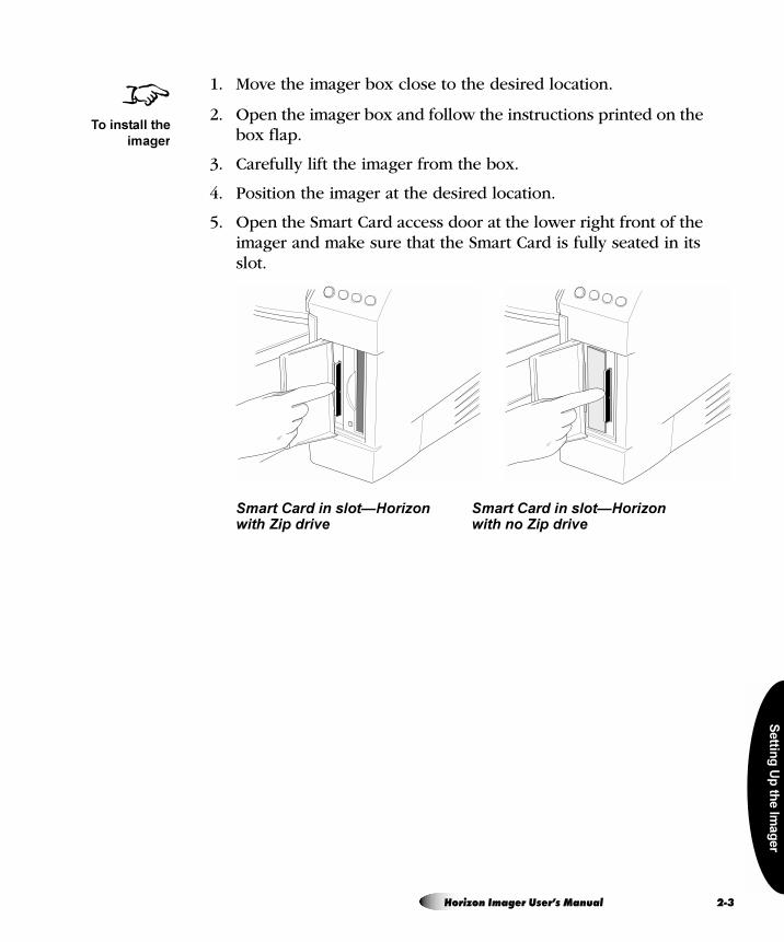
5. Open the Smart Card access door at the lower right front of the imager and make sure that the Smart Card is fully seated in its slot.
Smart Card in slot—Horizon Smart Card in slot—Horizonwith Zip drive with no Zip drive
8To install the
imager
Horizon Imager User’s Manual 2-3
2-4
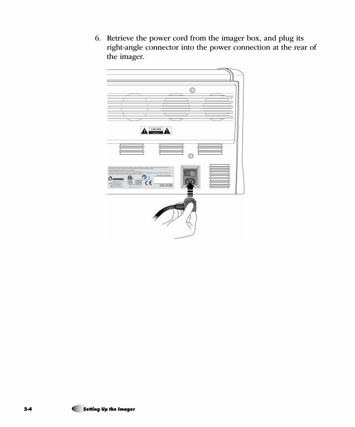
6. Retrieve the power cord from the imager box, and plug its right-angle connector into the power connection at the rear of the imager.
Setting Up the Imager
Settin
g U
p th
e Im
ag
er
7. Plug the other end of the power cord into a suitable receptacle or into a UPS.
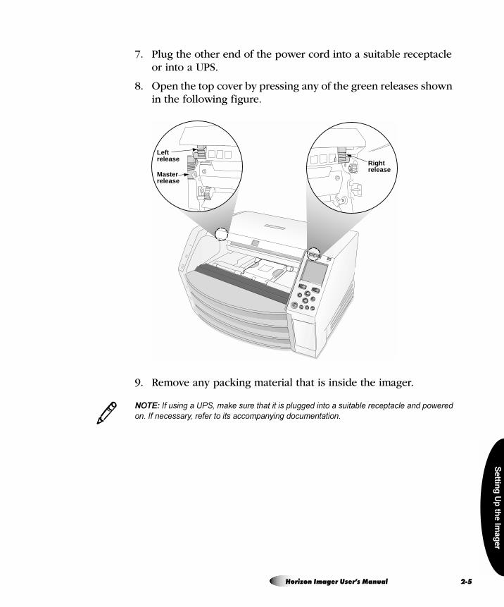
8. Open the top cover by pressing any of the green releases shown in the following figure.
9. Remove any packing material that is inside the imager.
NOTE: If using a UPS, make sure that it is plugged into a suitable receptacle and powered
on. If necessary, refer to its accompanying documentation.
Rightrelease
Leftrelease
Masterrelease
3
Horizon Imager User’s Manual 2-5
2-6
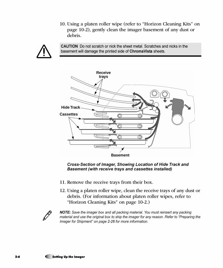
10. Using a platen roller wipe (refer to “Horizon Cleaning Kits” on page 10-2), gently clean the imager basement of any dust or debris.
Cross-Section of Imager, Showing Location of Hide Track and Basement (with receive trays and cassettes installed)
11. Remove the receive trays from their box.
12. Using a platen roller wipe, clean the receive trays of any dust or debris. (For information about platen roller wipes, refer to “Horizon Cleaning Kits” on page 10-2.)
NOTE: Save the imager box and all packing material. You must reinsert any packing
material and use the original box to ship the imager for any reason. Refer to “Preparing the
Imager for Shipment” on page 2-26 for more information.
CAUTION Do not scratch or nick the sheet metal. Scratches and nicks in the
basement will damage the printed side of ChromaVista sheets.
Receivetrays
Cassettes
Hide Track
Basement
3
Setting Up the Imager
Settin
g U
p th
e Im
ag
er
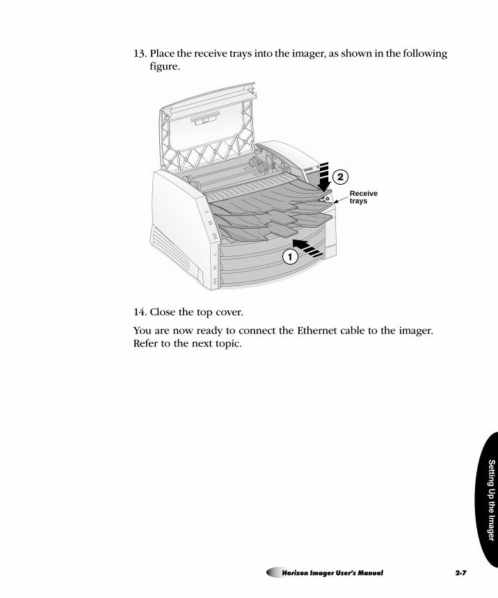
13. Place the receive trays into the imager, as shown in the following figure.
14. Close the top cover.
You are now ready to connect the Ethernet cable to the imager. Refer to the next topic.
Receivetrays
Horizon Imager User’s Manual 2-7
2-8
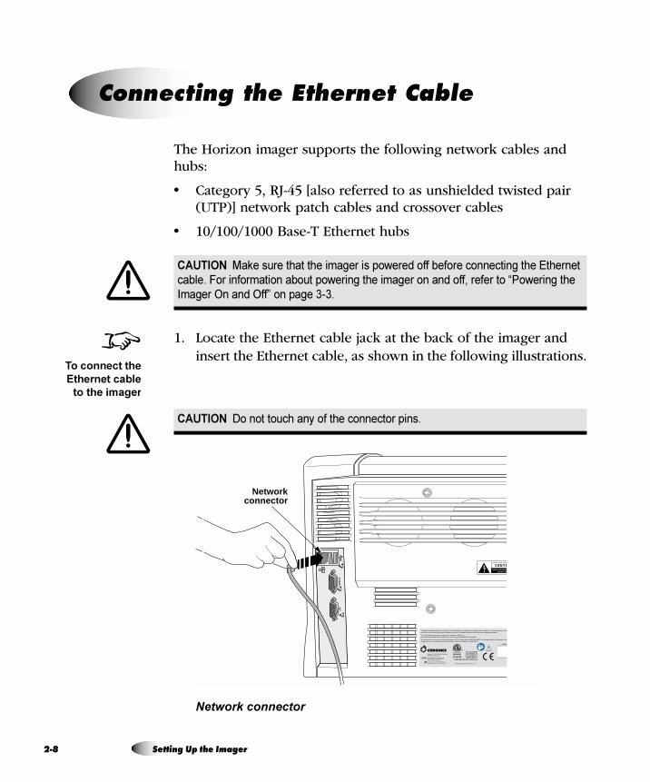
The Horizon imager supports the following network cables and hubs:
• Category 5, RJ-45 [also referred to as unshielded twisted pair (UTP)] network patch cables and crossover cables
• 10/100/1000 Base-T Ethernet hubs
1. Locate the Ethernet cable jack at the back of the imager and insert the Ethernet cable, as shown in the following illustrations.
Network connector
`çååÉÅíáåÖ=íÜÉ=bíÜÉêåÉí=`~ÄäÉ
CAUTION Make sure that the imager is powered off before connecting the Ethernet
cable. For information about powering the imager on and off, refer to “Powering the
Imager On and Off” on page 3-3.
CAUTION Do not touch any of the connector pins.
8To connect the
Ethernet cable
to the imager
CONS
OLE
UPS
Networkconnector
Setting Up the Imager

Settin
g U
p th
e Im
ag
er
NOTE: Depending on the specific configuration, your imager may include an optional
Ethernet filter cable. If provided, make sure to insert the Ethernet filter cable into the imager
network connector. Then insert the Ethernet cable into the Ethernet filter cable.
NOTE: Your imager may include an optional modem. The modem connectors look similar to
the network connector (but are slightly smaller). Make sure you insert the Ethernet cable jack
into the network connector. For more information about the modem (if there is one), refer to
the additional modem documentation that came with the imager.
2. Connect the other end of the Ethernet cable to the Ethernet hub or, if your configuration includes only a workstation and the imager, to the workstation’s Ethernet jack.
NOTE: When connecting the imager to only one workstation, you must use a special
Ethernet cable, called a crossover cable. This cable eliminates the need for a hub.
Optionally, you could still connect the imager and the single workstation using two standard
Ethernet patch cables and a hub. This would allow for future expansion of the network.
You are now ready to power on the imager. Refer to the next topic.
3
3
3
Horizon Imager User’s Manual 2-9
2-1
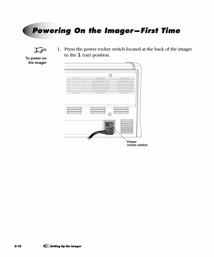
1. Press the power rocker switch located at the back of the imager to the 1 (on) position.
mçïÉêáåÖ=lå=íÜÉ=fã~ÖÉêÔcáêëí=qáãÉ
8To power on
the imager
Power rocker switch
0 Setting Up the Imager
Settin
g U
p th
e Im
ag
er
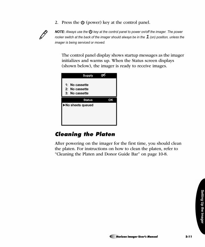
2. Press the (power) key at the control panel.
NOTE: Always use the key at the control panel to power on/off the imager. The power
rocker switch at the back of the imager should always be in the 1 (on) position, unless the
imager is being serviced or moved.
The control panel display shows startup messages as the imager initializes and warms up. When the Status screen displays (shown below), the imager is ready to receive images.
`äÉ~åáåÖ=íÜÉ=mä~íÉå
After powering on the imager for the first time, you should clean the platen. For instructions on how to clean the platen, refer to “Cleaning the Platen and Donor Guide Bar” on page 10-8.
Supply
1: No cassette
2: No cassette
3: No cassette
Status OK
�No sheets queued
3
Horizon Imager User’s Manual 2-11
2-1
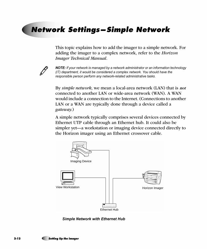
This topic explains how to add the imager to a simple network. For adding the imager to a complex network, refer to the Horizon Imager Technical Manual.
NOTE: If your network is managed by a network administrator or an information technology
(IT) department, it would be considered a complex network. You should have the
responsible person perform any network-related administrative tasks.
By simple network, we mean a local-area network (LAN) that is not connected to another LAN or wide-area network (WAN). A WAN would include a connection to the Internet. (Connections to another LAN or a WAN are typically done through a device called a gateway.)
A simple network typically comprises several devices connected by Ethernet UTP cable through an Ethernet hub. It could also be simpler yet—a workstation or imaging device connected directly to the Horizon imager using an Ethernet crossover cable.
Simple Network with Ethernet Hub
kÉíïçêâ=pÉííáåÖëÔpáãéäÉ=kÉíïçêâ
3
View Workstation Horizon Imager
Ethernet Hub
Imaging Device
2 Setting Up the Imager
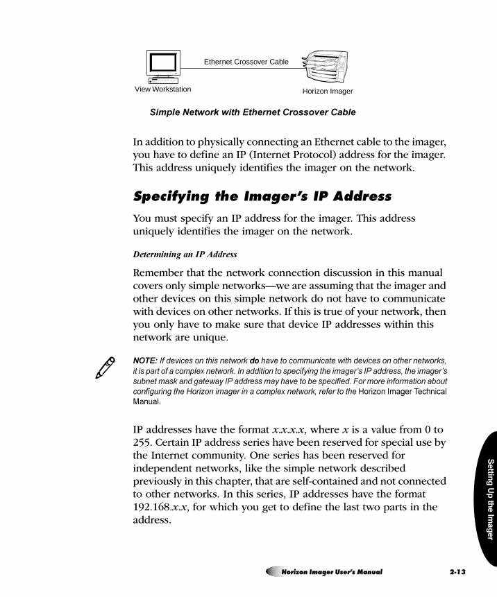
Settin
g U
p th
e Im
ag
er
Simple Network with Ethernet Crossover Cable
In addition to physically connecting an Ethernet cable to the imager, you have to define an IP (Internet Protocol) address for the imager. This address uniquely identifies the imager on the network.
péÉÅáÑóáåÖ=íÜÉ=fã~ÖÉêÛë=fm=^ÇÇêÉëë
You must specify an IP address for the imager. This address uniquely identifies the imager on the network.
Determining an IP Address
Remember that the network connection discussion in this manual covers only simple networks—we are assuming that the imager and other devices on this simple network do not have to communicate with devices on other networks. If this is true of your network, then you only have to make sure that device IP addresses within this network are unique.
NOTE: If devices on this network do have to communicate with devices on other networks,
it is part of a complex network. In addition to specifying the imager’s IP address, the imager’s
subnet mask and gateway IP address may have to be specified. For more information about
configuring the Horizon imager in a complex network, refer to the Horizon Imager Technical
Manual.
IP addresses have the format x.x.x.x, where x is a value from 0 to 255. Certain IP address series have been reserved for special use by the Internet community. One series has been reserved for independent networks, like the simple network described previously in this chapter, that are self-contained and not connected to other networks. In this series, IP addresses have the format 192.168.x.x, for which you get to define the last two parts in the address.
View Workstation Horizon Imager
Ethernet Crossover Cable
3
Horizon Imager User’s Manual 2-13
2-1
While you can certainly use your own IP address numbering scheme in your simple network, you might want to adopt this Internet convention. So, you might assign the IP addresses as follows:
• 192.168.1.200 to the Horizon imager
• 192.168.1.201 to an image viewing workstation on the network
• 192.168.1.202 to a second workstation
• 192.168.1.203 to an imaging device
And so on.
TIP: Labeling each device with its IP address
For convenience, you may want to affix a label to each device in the network that shows the
device’s IP address.
Specifying the Imager’s IP Address at the Control Panel
NOTE: For a simple network, you will only need to define the imager’s base IP address. You
can leave all other network settings for the imager at their default values.
NOTE: For instructions on how to use the imager’s control panel and menus, refer to
Chapter 3.
NOTE: After entering the base IP address, note that the imager will reboot once you exit the
menus so that the software can be properly updated with the new value.
/
3
3
3
4 Setting Up the Imager
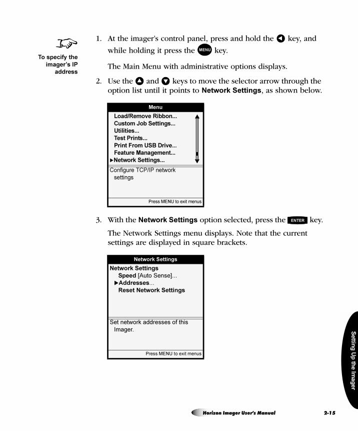
Settin
g U
p th
e Im
ag
er
1. At the imager’s control panel, press and hold the key, and
while holding it press the key.
The Main Menu with administrative options displays.
2. Use the and keys to move the selector arrow through the option list until it points to Network Settings, as shown below.
3. With the Network Settings option selected, press the key.
The Network Settings menu displays. Note that the current settings are displayed in square brackets.
Menu
Load/Remove Ribbon...
Custom Job Settings...
Utilities...
Test Prints...
Print From USB Drive...
Feature Management...
�Network Settings...
Configure TCP/IP network
settings
Press MENU to exit menus
Network Settings
Network Settings
Speed [Auto Sense]...
�Addresses...
Reset Network Settings
Set network addresses of this
Imager.
Press MENU to exit menus
8To specify the
imager’s IP
address
�
MENU
� �
ENTER
Horizon Imager User’s Manual 2-15
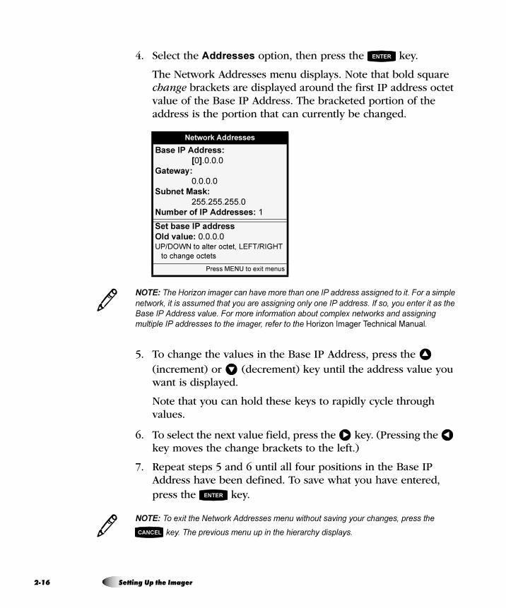
2-1
4. Select the Addresses option, then press the key.
The Network Addresses menu displays. Note that bold square change brackets are displayed around the first IP address octet value of the Base IP Address. The bracketed portion of the address is the portion that can currently be changed.
NOTE: The Horizon imager can have more than one IP address assigned to it. For a simple
network, it is assumed that you are assigning only one IP address. If so, you enter it as the
Base IP Address value. For more information about complex networks and assigning
multiple IP addresses to the imager, refer to the Horizon Imager Technical Manual.
5. To change the values in the Base IP Address, press the (increment) or (decrement) key until the address value you want is displayed.
Note that you can hold these keys to rapidly cycle through values.
6. To select the next value field, press the key. (Pressing the key moves the change brackets to the left.)
7. Repeat steps 5 and 6 until all four positions in the Base IP Address have been defined. To save what you have entered, press the key.
NOTE: To exit the Network Addresses menu without saving your changes, press the
key. The previous menu up in the hierarchy displays.
Network Addresses
Base IP Address:
[0].0.0.0
Gateway:
0.0.0.0
Subnet Mask:
255.255.255.0
Number of IP Addresses: 1
Set base IP address
Old value: 0.0.0.0UP/DOWN to alter octet, LEFT/RIGHT
to change octets
Press MENU to exit menus
ENTER
3
�
�
� �
ENTER
3 CANCEL
6 Setting Up the Imager
Settin
g U
p th
e Im
ag
er
8. Press the or key to leave the Network Settings menu.
A message states that the imager will automatically reboot when
you press the key to exit the Main Menu.
9. Press the key to acknowledge the message.
10. When you are finished specifying the IP address and want to
exit the Main Menu, press the key.
Because the base IP address was defined, the imager reboots so that it can be identified properly on the network.
NOTE: You can reset the network settings to their default values at any time by selecting the
Reset Network Settings option in the Network Settings menu.
péÉÅáÑóáåÖ=fm=^ÇÇêÉëëÉë=Ñçê=líÜÉê=aÉîáÅÉë=çå=íÜÉ=kÉíïçêâ
Just as you did for the Horizon imager, you must specify the IP addresses for each of the other devices on the network. How you do this varies, depending on the device and its operating system. For this reason, you will have to refer to the documentation or online help that comes with the device for specific instructions.
For more information about IP addressing conventions, refer to the Horizon Imager Technical Manual.
After setting the imager’s IP address, you can load media cassettes and, optionally, load a ribbon to support color prints. For more information about how to load media, refer to “Inserting or Changing Cassettes” on page 4-4 and “Changing the Ribbon (ChromaVista)” on page 4-8.
CANCEL �
MENU
ENTER
MENU
3
iç~ÇáåÖ=jÉÇá~
Horizon Imager User’s Manual 2-17
2-1
After the Horizon imager is set up and powered on, you should print the Imager Status test print to verify imager operation and save a record of the imager’s information. There are several other test patterns to choose from to allow you to check the quality of printed images.
NOTE: For instructions on how to use the imager’s control panel and menus, refer to
Chapter 3.
1. At the control panel, press the key.
The Main Menu displays.
2. Insert a supply cassette for the media type on which you want to print the Imager Status test print into one of the supply slots.
NOTE: For detailed procedures on how to load media, refer to “Inserting or Changing
Cassettes” on page 4-4.
3. From the Main Menu, select the following options.
Test Prints
media type (that is, the type inserted in step 2)
media size (that is, the media size inserted in step 2)
Imager Status
Copies
The number of copies to print displays.
4. Change the number of copies or leave as is, then press the key.
The imager prints the Imager Status sheet.
NOTE: If a cassette with the selected media size and type is not currently loaded in the
imager, or you are printing to ChromaVista color media and a ribbon is not loaded, the test
print will not print. The imager will prompt you to insert the proper supply cassette and/or
color ribbon.
mêáåíáåÖ=íÜÉ=fã~ÖÉê=pí~íìë=qÉëí=mêáåí
3
8To print the
Imager Status
test print
MENU
3
ENTER
3
8 Setting Up the Imager
Settin
g U
p th
e Im
ag
er
After generating a test print, try printing a sample image from each imaging device and/or image viewing workstation on the network to verify whether the network settings and cable connections are properly configured.
• If printing from one of the devices does not work, check that the device is properly connected to the network and that its IP address information is properly configured.
• If you cannot print to the Horizon imager from any device, check that the imager is properly connected to the network and that its IP address information is properly configured.
For procedures on how to print to the Horizon imager:
• To print from a DICOM application, refer to Chapter 5.
• To print from an application via PostScript, refer to Chapter 6.
• To print images from backup media, refer to the Horizon Imager Technical Manual.
• To send print jobs using FTP or LPR, refer to Chapter 7.
• To send print jobs using an SA-2000 analog framegrabber, refer to the SA-2000 Operator Manual.
qÉëíáåÖ=kÉíïçêâ=mêáåíáåÖ
Horizon Imager User’s Manual 2-19
2-2
The Horizon imager is shipped with a service login account that provides web browser and Telnet access to service utilities on the imager. The service default password should be changed as soon as possible to prevent compromising security access to the imager. For information about the service login, refer to the Horizon Imager Technical Manual.
Before starting normal operation of the imager, you may want to adjust the appearance of printed images to suit the preferences of your site. For information about how to make these adjustments, refer to Chapter 9.
Once you have the imager initially configured as you want it using the procedures in this chapter and Chapter 8, you should save those configuration settings to the appropriate backup media for your imager hardware. (Refer to “Hardware Variations” on page xli.)
If the imager settings ever become modified to an unsatisfactory state, you can always restore the imager to these initial settings from the backup media. Also, if the Smart Card ever fails, you can use the backup media to restore the imager’s configuration settings.
`Ü~åÖáåÖ=íÜÉ=pÉêîáÅÉ=m~ëëïçêÇ
^ÇàìëíáåÖ=fã~ÖÉ=^ééÉ~ê~åÅÉ
p~îáåÖ=íÜÉ=`çåÑáÖìê~íáçå=pÉííáåÖë
0 Setting Up the Imager
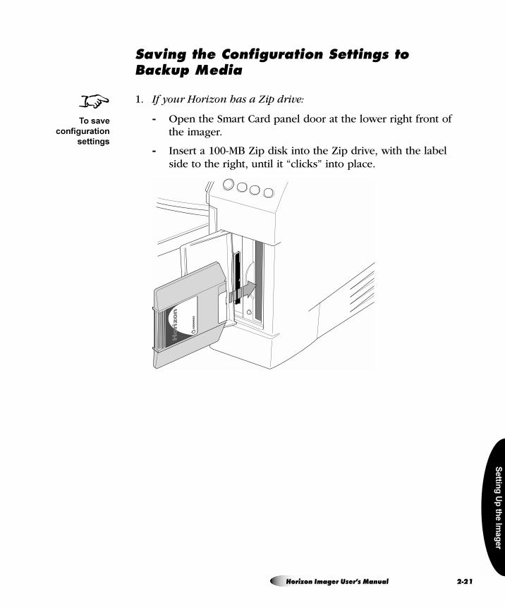
Settin
g U
p th
e Im
ag
er
p~îáåÖ=íÜÉ=`çåÑáÖìê~íáçå=pÉííáåÖë=íç=_~Åâìé=jÉÇá~
1. If your Horizon has a Zip drive:
- Open the Smart Card panel door at the lower right front of the imager.
- Insert a 100-MB Zip disk into the Zip drive, with the label side to the right, until it “clicks” into place.
8To save
configuration
settings
Horizon Imager User’s Manual 2-21
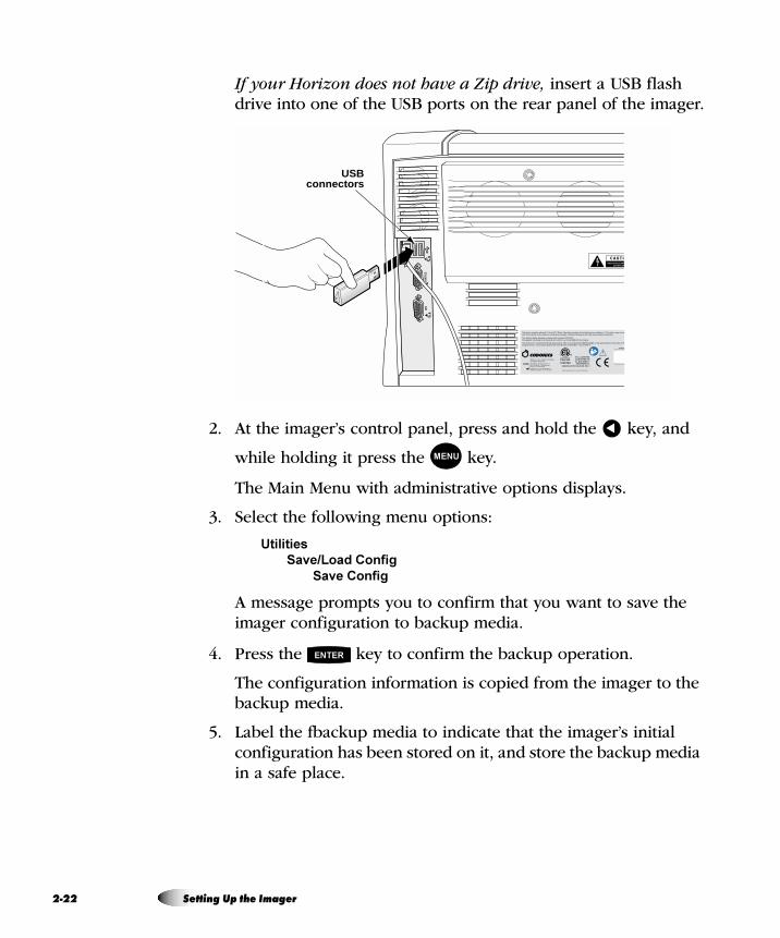
2-2
If your Horizon does not have a Zip drive, insert a USB flash drive into one of the USB ports on the rear panel of the imager.
2. At the imager’s control panel, press and hold the key, and
while holding it press the key.
The Main Menu with administrative options displays.
3. Select the following menu options:
Utilities
Save/Load Config
Save Config
A message prompts you to confirm that you want to save the imager configuration to backup media.
4. Press the key to confirm the backup operation.
The configuration information is copied from the imager to the backup media.
5. Label the fbackup media to indicate that the imager’s initial configuration has been stored on it, and store the backup media in a safe place.
CONS
OLE
UPS
USBconnectors
�
MENU
ENTER
2 Setting Up the Imager
Settin
g U
p th
e Im
ag
er
j~å~ÖáåÖ=vçìê=_~Åâìé=jÉÇá~
Once you create a backup Zip disk or USB flash drive with the initial imager settings, you may not want to reuse that backup media. If you run another Save Config function with this backup media inserted, the old configuration settings will be overwritten.
It is recommended that each time you make significant changes to the imager’s settings, you save them to a separate backup media. Only reuse a backup media if you are certain that you would not want to restore the configuration settings already stored on it.
Keep all backup media in a safe place.
Horizon Imager User’s Manual 2-23
2-2
oÉëíçêáåÖ=íÜÉ=`çåÑáÖìê~íáçå=pÉííáåÖë=Ñêçã=_~Åâìé=jÉÇá~
1. If your Horizon has a Zip drive, open the SmartCard access door at the lower right front of the imager and insert the 100-MB backup Zip disk into the imager Zip drive.
If your Horizon does not have a Zip drive, insert the backup USB flash drive into one of the USB ports on the rear panel.
2. At the imager’s control panel, press and hold the key, and
while holding it press the key.
The Main Menu with administrative options displays.
3. Select the following menu options:
Utilities
Save/Load Config
Load Config
A message prompts you to confirm that you want to load the imager configuration from the backup media.
4. Press the key to confirm the restore operation.
The configuration is copied onto the imager from the backup media. Then the imager reboots so that the restored settings can take effect.
8To restore
configuration
settings
�
MENU
ENTER
4 Setting Up the Imager
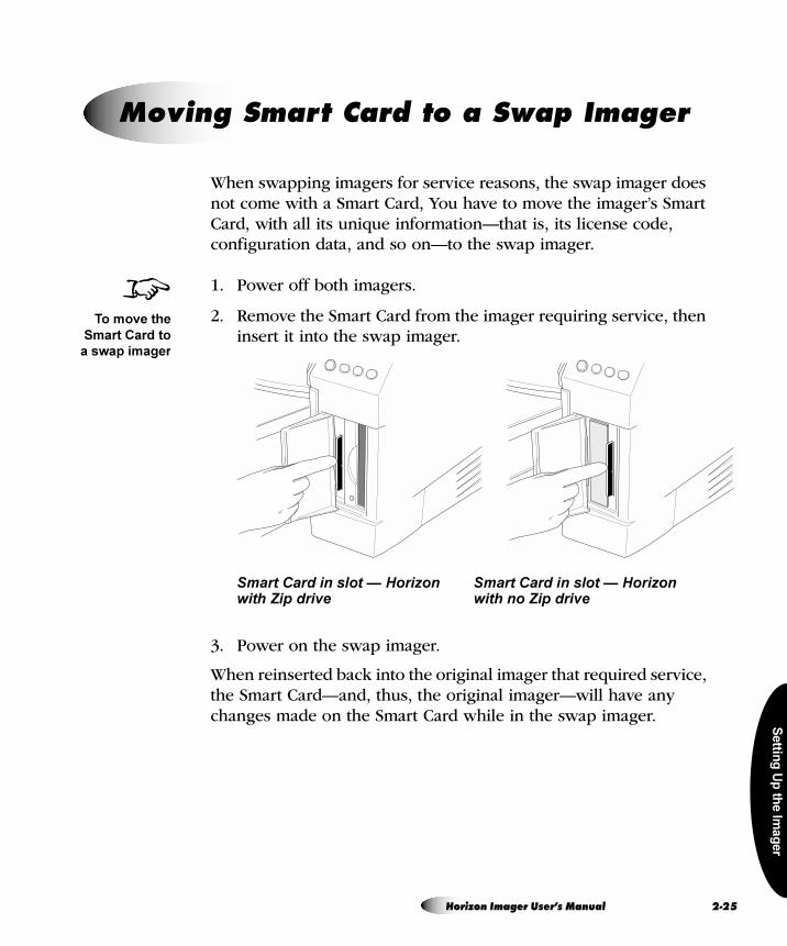
Settin
g U
p th
e Im
ag
er
When swapping imagers for service reasons, the swap imager does not come with a Smart Card, You have to move the imager’s Smart Card, with all its unique information—that is, its license code, configuration data, and so on—to the swap imager.
1. Power off both imagers.
2. Remove the Smart Card from the imager requiring service, then insert it into the swap imager.
Smart Card in slot — Horizon Smart Card in slot — Horizon with Zip drive with no Zip drive
3. Power on the swap imager.
When reinserted back into the original imager that required service, the Smart Card—and, thus, the original imager—will have any changes made on the Smart Card while in the swap imager.
jçîáåÖ=pã~êí=`~êÇ=íç=~=pï~é=fã~ÖÉê
8To move the
Smart Card to
a swap imager
Horizon Imager User’s Manual 2-25
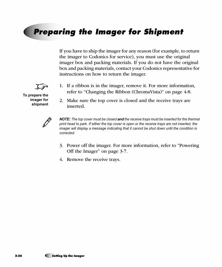
2-2
If you have to ship the imager for any reason (for example, to return the imager to Codonics for service), you must use the original imager box and packing materials. If you do not have the original box and packing materials, contact your Codonics representative for instructions on how to return the imager.
1. If a ribbon is in the imager, remove it. For more information, refer to “Changing the Ribbon (ChromaVista)” on page 4-8.
2. Make sure the top cover is closed and the receive trays are inserted.
NOTE: The top cover must be closed and the receive trays must be inserted for the thermal
print head to park. If either the top cover is open or the receive trays are not inserted, the
imager will display a message indicating that it cannot be shut down until the condition is
corrected.
3. Power off the imager. For more information, refer to “Powering Off the Imager” on page 3-7.
4. Remove the receive trays.
mêÉé~êáåÖ=íÜÉ=fã~ÖÉê=Ñçê=pÜáéãÉåí
8To prepare the
imager for
shipment
3
6 Setting Up the Imager
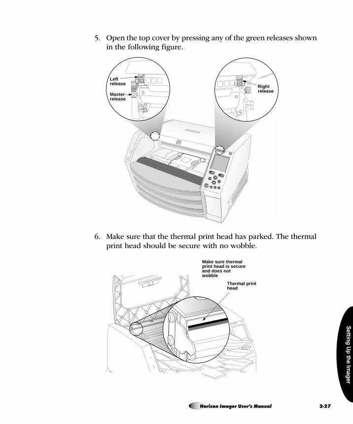
Settin
g U
p th
e Im
ag
er
5. Open the top cover by pressing any of the green releases shown in the following figure.
6. Make sure that the thermal print head has parked. The thermal print head should be secure with no wobble.
Rightrelease
Leftrelease
Masterrelease
Thermal printhead
Make sure thermalprint head is secureand does notwobble
Horizon Imager User’s Manual 2-27
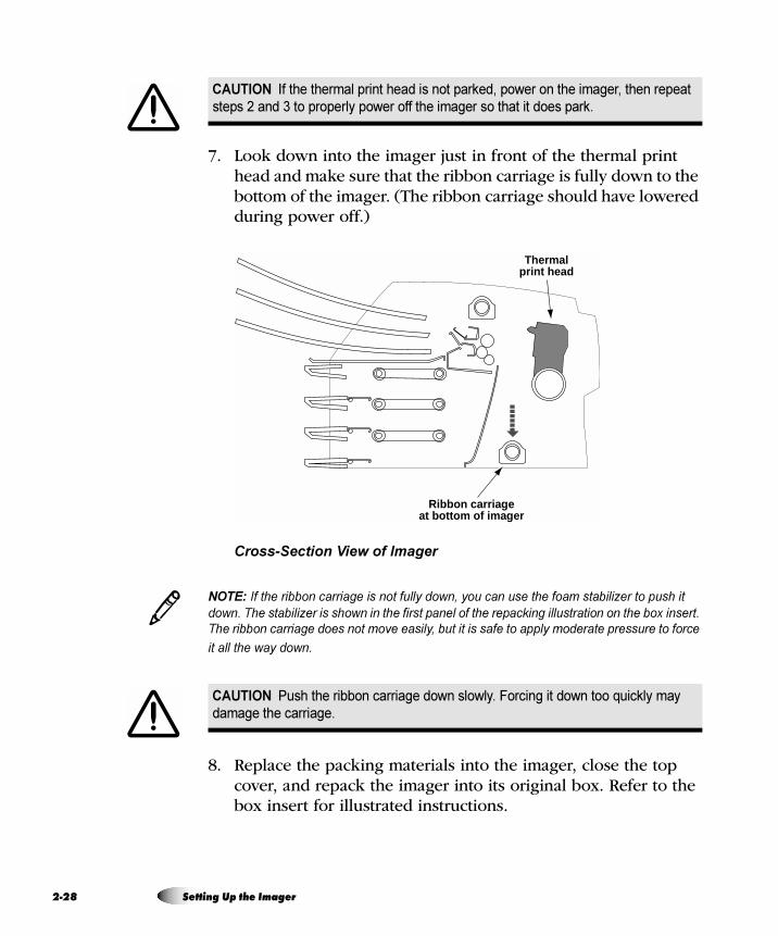
2-2
7. Look down into the imager just in front of the thermal print head and make sure that the ribbon carriage is fully down to the bottom of the imager. (The ribbon carriage should have lowered during power off.)
Cross-Section View of Imager
NOTE: If the ribbon carriage is not fully down, you can use the foam stabilizer to push it
down. The stabilizer is shown in the first panel of the repacking illustration on the box insert.
The ribbon carriage does not move easily, but it is safe to apply moderate pressure to force
it all the way down.
8. Replace the packing materials into the imager, close the top cover, and repack the imager into its original box. Refer to the box insert for illustrated instructions.
CAUTION If the thermal print head is not parked, power on the imager, then repeat
steps 2 and 3 to properly power off the imager so that it does park.
CAUTION Push the ribbon carriage down slowly. Forcing it down too quickly may
damage the carriage.
Ribbon carriageat bottom of imager
Thermalprint head
3
8 Setting Up the Imager
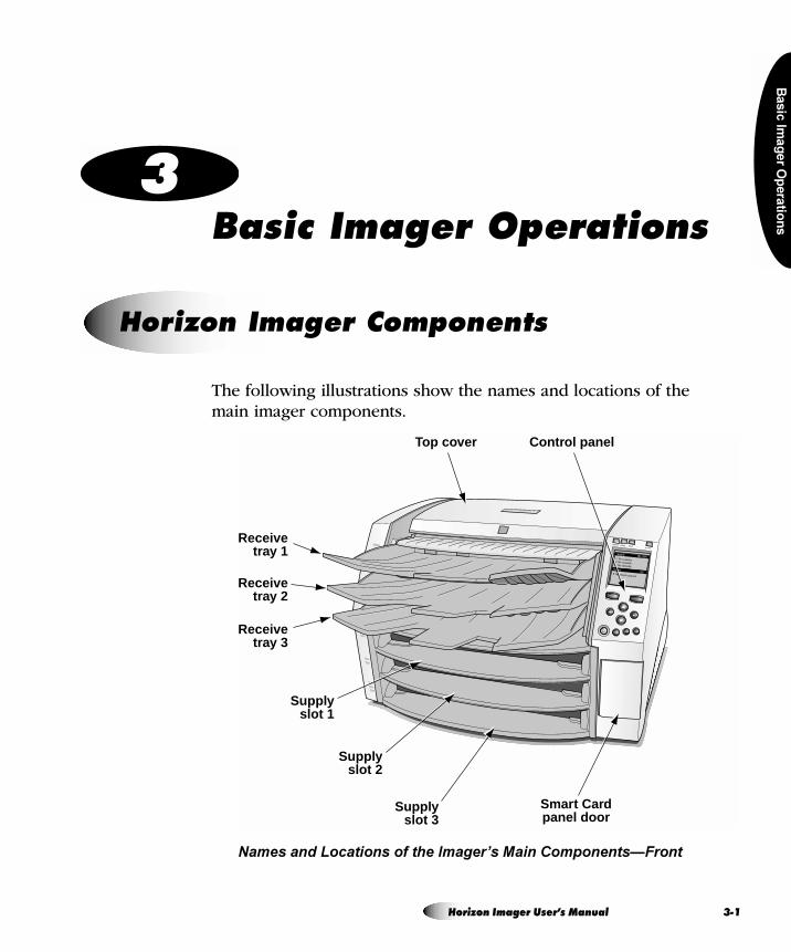
Ba
sic
Ima
ge
r Op
era
tion
s
= P_~ëáÅ=fã~ÖÉê=léÉê~íáçåë
The following illustrations show the names and locations of the main imager components.
Names and Locations of the Imager’s Main Components—Front
eçêáòçå=fã~ÖÉê=`çãéçåÉåíë
Control panelTop cover
Smart Cardpanel door
Receivetray 1
Supplyslot 1
Supplyslot 2
Supplyslot 3
Receivetray 2
Receivetray 3
Horizon Imager User’s Manual 3-1
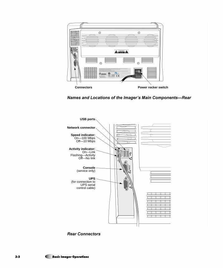
3-2
Names and Locations of the Imager’s Main Components—Rear
Rear Connectors
CONS
OLE
UPS
Power rocker switchConnectors
CONS
OLE
UPS
Network connector
Speed indicator:On—100 Mbps
Off—10 Mbps
Activity indicator:On—Link
Flashing—ActivityOff—No link
Console(service only)
UPS(for connection to
UPS serialcontrol cable)
USB ports
Basic Imager Operations
Ba
sic
Ima
ge
r Op
era
tion
s
mçïÉêáåÖ=lå=íÜÉ=fã~ÖÉê
Press the (power) key at the control panel.
When the imager is powered on, startup status messages are displayed at the control panel display. The startup process takes 2 to 3 minutes. When the Status screen displays, the imager is ready to receive images.
NOTE: There are ways to get more detailed information about the imager’s operating status.
For more information, refer to the Horizon Imager Technical Manual.
mçïÉêáåÖ=íÜÉ=fã~ÖÉê=lå=~åÇ=lÑÑ
8To power on
the imager
3
Horizon Imager User’s Manual 3-3
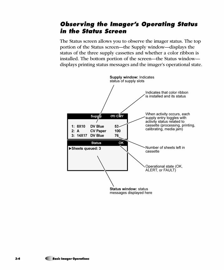
3-4
lÄëÉêîáåÖ=íÜÉ=fã~ÖÉêÛë=léÉê~íáåÖ=pí~íìë=áå=íÜÉ=pí~íìë=pÅêÉÉå
The Status screen allows you to observe the imager status. The top portion of the Status screen—the Supply window—displays the status of the three supply cassettes and whether a color ribbon is installed. The bottom portion of the screen—the Status window—displays printing status messages and the imager’s operational state.
Supply CMY
1: 8X10 DV Blue 53
2: A CV Paper 100
3: 14X17 DV Blue 76
Status OK
�Sheets queued: 3
Indicates that color ribbon is installed and its status
Supply window: Indicates status of supply slots
Number of sheets left in cassette
Status window: status messages displayed here
Operational state (OK, ALERT, or FAULT)
When activity occurs, each supply entry toggles with activity status related to cassette (processing, printing, calibrating, media jam)
Basic Imager Operations
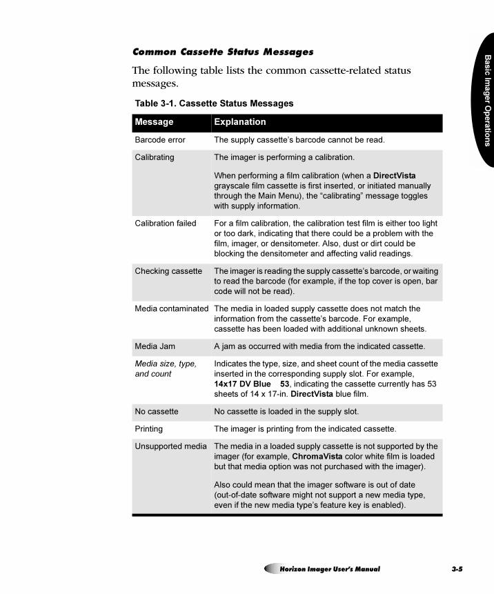
Ba
sic
Ima
ge
r Op
era
tion
s
`çããçå=`~ëëÉííÉ=pí~íìë=jÉëë~ÖÉë
The following table lists the common cassette-related status messages.
Table 3-1. Cassette Status Messages
Message Explanation
Barcode error The supply cassette’s barcode cannot be read.
Calibrating The imager is performing a calibration.
When performing a film calibration (when a DirectVista
grayscale film cassette is first inserted, or initiated manually
through the Main Menu), the “calibrating” message toggles
with supply information.
Calibration failed For a film calibration, the calibration test film is either too light
or too dark, indicating that there could be a problem with the
film, imager, or densitometer. Also, dust or dirt could be
blocking the densitometer and affecting valid readings.
Checking cassette The imager is reading the supply cassette’s barcode, or waiting
to read the barcode (for example, if the top cover is open, bar
code will not be read).
Media contaminated The media in loaded supply cassette does not match the
information from the cassette’s barcode. For example,
cassette has been loaded with additional unknown sheets.
Media Jam A jam as occurred with media from the indicated cassette.
Media size, type, and count
Indicates the type, size, and sheet count of the media cassette
inserted in the corresponding supply slot. For example,
14x17 DV Blue 53, indicating the cassette currently has 53
sheets of 14 x 17-in. DirectVista blue film.
No cassette No cassette is loaded in the supply slot.
Printing The imager is printing from the indicated cassette.
Unsupported media The media in a loaded supply cassette is not supported by the
imager (for example, ChromaVista color white film is loaded
but that media option was not purchased with the imager).
Also could mean that the imager software is out of date
(out-of-date software might not support a new media type,
even if the new media type’s feature key is enabled).
Horizon Imager User’s Manual 3-5
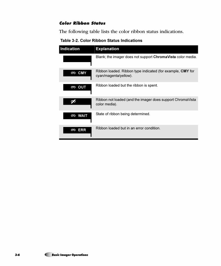
3-6
`çäçê=oáÄÄçå=pí~íìë
The following table lists the color ribbon status indications.
Table 3-2. Color Ribbon Status Indications
Indication Explanation
Blank; the imager does not support ChromaVista color media.
Ribbon loaded. Ribbon type indicated (for example, CMY for
cyan/magenta/yellow).
Ribbon loaded but the ribbon is spent.
Ribbon not loaded (and the imager does support ChromaVista
color media).
State of ribbon being determined.
Ribbon loaded but in an error condition.
CMY
OUT
WAIT
ERR
Basic Imager Operations
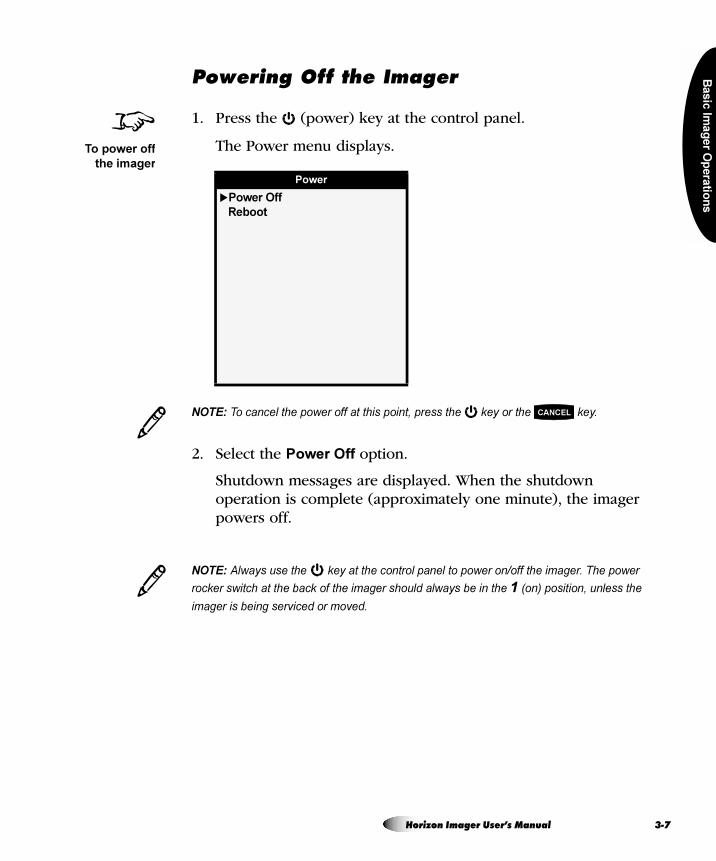
Ba
sic
Ima
ge
r Op
era
tion
s
mçïÉêáåÖ=lÑÑ=íÜÉ=fã~ÖÉê
1. Press the (power) key at the control panel.
The Power menu displays.
NOTE: To cancel the power off at this point, press the key or the key.
2. Select the Power Off option.
Shutdown messages are displayed. When the shutdown operation is complete (approximately one minute), the imager powers off.
NOTE: Always use the key at the control panel to power on/off the imager. The power
rocker switch at the back of the imager should always be in the 1 (on) position, unless the
imager is being serviced or moved.
Power
�Power Off
Reboot
8To power off
the imager
3CANCEL
3
Horizon Imager User’s Manual 3-7
3-8
TIP: Bypassing the Power menu
To start the shutdown process without having to display the Power menu, press and hold the
key for a few seconds, until you see shutdown messages appear in the control panel
display.
CAUTION If the imager is powered off using the key, unprinted queued jobs are
saved and will finish printing once the imager is powered on again (you can purge all
jobs). However, if the imager is powered off using the rocker switch in the back or
power is interrupted (for example, an unexpected power failure), queued jobs may be
lost.
WARNING When servicing the imager, always power it off using the key, turn
the rocker switch in the back to the 0 (off) position, then unplug the imager.
/
Basic Imager Operations
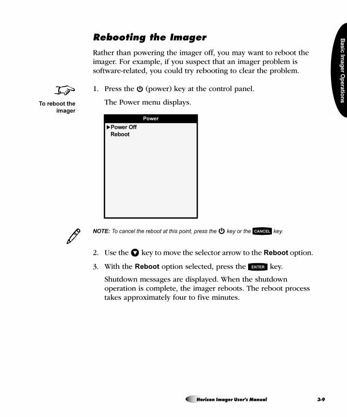
Ba
sic
Ima
ge
r Op
era
tion
s
oÉÄççíáåÖ=íÜÉ=fã~ÖÉê
Rather than powering the imager off, you may want to reboot the imager. For example, if you suspect that an imager problem is software-related, you could try rebooting to clear the problem.
1. Press the (power) key at the control panel.
The Power menu displays.
NOTE: To cancel the reboot at this point, press the key or the key.
2. Use the key to move the selector arrow to the Reboot option.
3. With the Reboot option selected, press the key.
Shutdown messages are displayed. When the shutdown operation is complete, the imager reboots. The reboot process takes approximately four to five minutes.
Power
�Power Off
Reboot
8To reboot the
imager
3CANCEL
�
ENTER
Horizon Imager User’s Manual 3-9
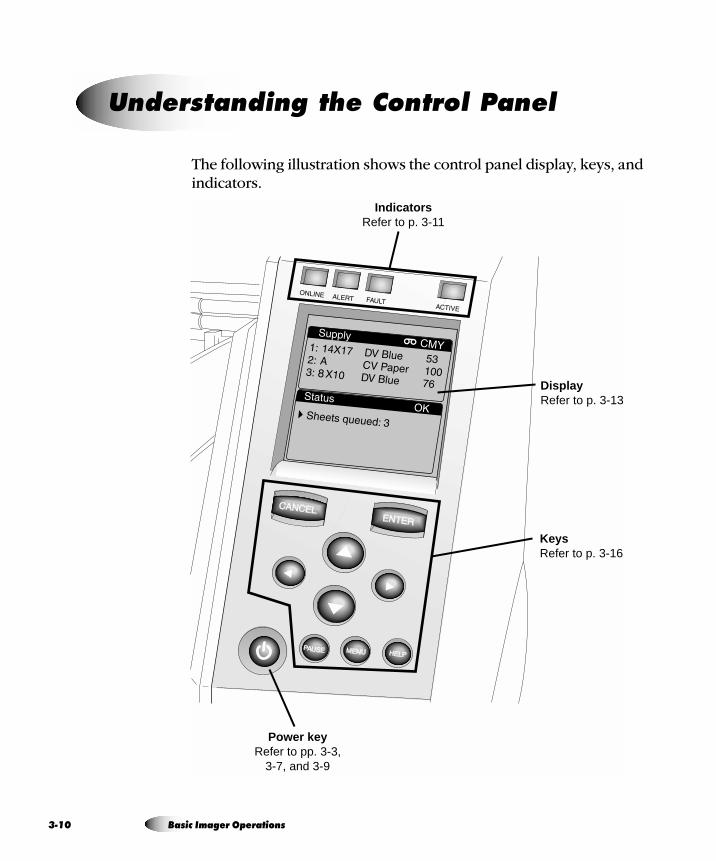
3-1
The following illustration shows the control panel display, keys, and indicators.
råÇÉêëí~åÇáåÖ=íÜÉ=`çåíêçä=m~åÉä
Indicators Refer to p. 3-11
Keys Refer to p. 3-16
Power key Refer to pp. 3-3,
3-7, and 3-9
Display Refer to p. 3-13
0 Basic Imager Operations
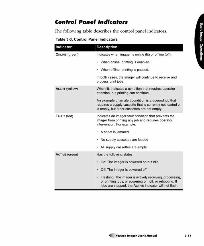
Ba
sic
Ima
ge
r Op
era
tion
s
`çåíêçä=m~åÉä=fåÇáÅ~íçêë
The following table describes the control panel indicators.
Table 3-3. Control Panel Indicators
Indicator Description
ONLINE (green) Indicates when imager is online (lit) or offline (off):
• When online, printing is enabled.
• When offline, printing is paused.
In both cases, the imager will continue to receive and
process print jobs.
ALERT (yellow) When lit, indicates a condition that requires operator
attention, but printing can continue.
An example of an alert condition is a queued job that
requires a supply cassette that is currently not loaded or
is empty, but other cassettes are not empty.
FAULT (red) Indicates an imager fault condition that prevents the
imager from printing any job and requires operator
intervention. For example:
• A sheet is jammed
• No supply cassettes are loaded
• All supply cassettes are empty
ACTIVE (green) Has the following states:
• On: The imager is powered on but idle.
• Off: The imager is powered off.
• Flashing: The imager is actively receiving, processing,
or printing jobs; or powering on, off, or rebooting. If
jobs are stopped, the ACTIVE indicator will not flash.
Horizon Imager User’s Manual 3-11
3-1
^äÉêí=~åÇ=c~ìäí=jÉëë~ÖÉë=~åÇ=íÜÉ=c~ìäí=qçåÉ
When the imager needs attention or an error occurs, the ALERT or FAULT indicator lights. Also, “ALERT” and “FAULT” are displayed in the Status screen’s title bar, and messages are displayed in the Status screen to help you respond properly to the condition.
If operator intervention is required (for example, there is a sheet jam), a Fault tone sounds. To stop the Fault tone, press any control panel key.
TIP: Controlling the Fault tone volume or turning it off
You can control the volume of the Fault tone, or turn it off. For more information, refer to the
Horizon Imager Technical Manual.
For more information about alert and fault messages and how to respond to them, refer to Chapter 12.
/
2 Basic Imager Operations
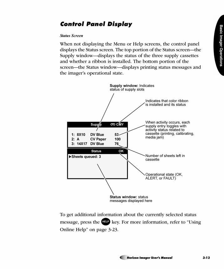
Ba
sic
Ima
ge
r Op
era
tion
s
`çåíêçä=m~åÉä=aáëéä~ó
Status Screen
When not displaying the Menu or Help screens, the control panel displays the Status screen. The top portion of the Status screen—the Supply window—displays the status of the three supply cassettes and whether a ribbon is installed. The bottom portion of the screen—the Status window—displays printing status messages and the imager’s operational state.
To get additional information about the currently selected status
message, press the key. For more information, refer to “Using
Online Help” on page 3-23.
Supply CMY
1: 8X10 DV Blue 53
2: A CV Paper 100
3: 14X17 DV Blue 76
Status OK
�Sheets queued: 3
Indicates that color ribbon is installed and its status
Supply window: Indicates status of supply slots
Number of sheets left in cassette
Status window: status messages displayed here
Operational state (OK, ALERT, or FAULT)
When activity occurs, each supply entry toggles with activity status related to cassette (printing, calibrating, media jam)
HELP
Horizon Imager User’s Manual 3-13
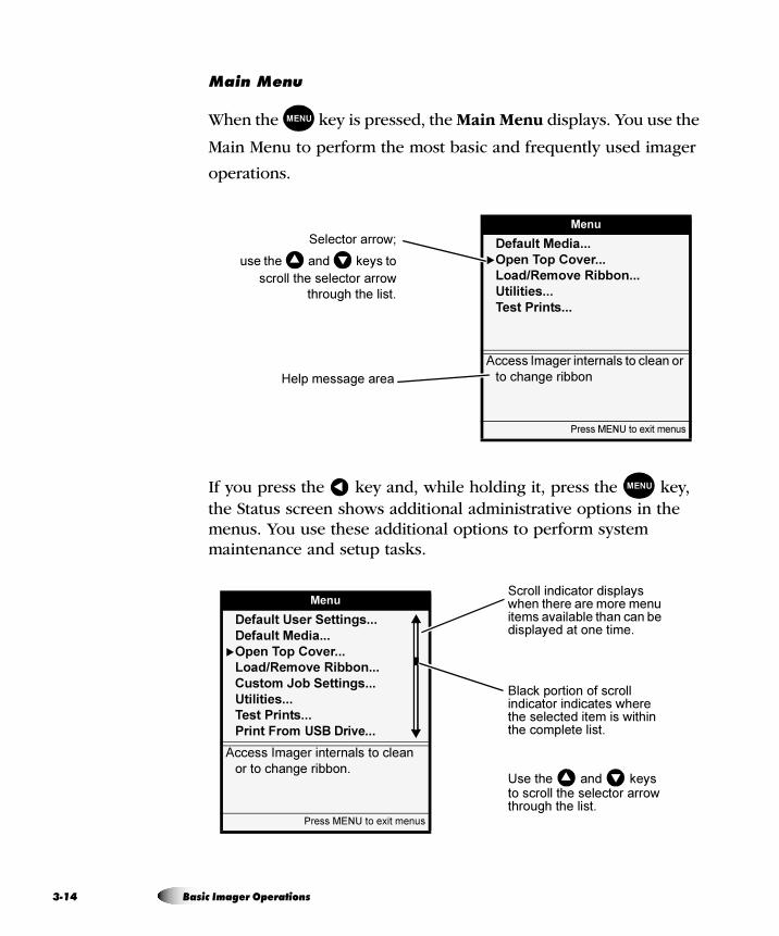
3-1
j~áå=jÉåì
When the key is pressed, the Main Menu displays. You use the
Main Menu to perform the most basic and frequently used imager
operations.
If you press the key and, while holding it, press the key, the Status screen shows additional administrative options in the menus. You use these additional options to perform system maintenance and setup tasks.
MENU
Menu
Default Media...
�Open Top Cover...
Load/Remove Ribbon...
Utilities...
Test Prints...
Access Imager internals to clean or
to change ribbon
Press MENU to exit menus
Selector arrow;
use the and keys to
scroll the selector arrow
through the list.
� �
Help message area
� MENU
Menu
Default User Settings...
Default Media...
�Open Top Cover...
Load/Remove Ribbon...
Custom Job Settings...
Utilities...
Test Prints...
Print From USB Drive...
Access Imager internals to clean
or to change ribbon.
Press MENU to exit menus
Scroll indicator displays when there are more menu items available than can be displayed at one time.
Black portion of scroll indicator indicates where the selected item is within the complete list.
Use the and keys to scroll the selector arrow through the list.
� �
4 Basic Imager Operations
Ba
sic
Ima
ge
r Op
era
tion
s
TIP: Wrapping around a scrollable list
Scrollable lists wrap around. That is, scrolling up past the first item displays the last items in
the list. Likewise, scrolling past the last item displays the first items in the list.
Press the key. The Status screen is displayed.
You must always display the Status screen to see the current status of the imager. For example, if a fault occurs while you are in a Menu screen, the FAULT indicator will light and you will hear the Fault
tone. However, to see the Fault message, you must press the key to exit the menus and display the Status screen.
/
8To exit the
Menu screens
MENU
MENU
Horizon Imager User’s Manual 3-15
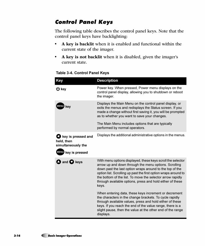
3-1
`çåíêçä=m~åÉä=hÉóë
The following table describes the control panel keys. Note that the control panel keys have backlighting:
• A key is backlit when it is enabled and functional within the current state of the imager.
• A key is not backlit when it is disabled, given the imager’s current state.
Table 3-4. Control Panel Keys
Key Description
key Power key. When pressed, Power menu displays on the
control panel display, allowing you to shutdown or reboot
the imager.
keyDisplays the Main Menu on the control panel display, or
exits the menus and redisplays the Status screen. If you
made a change without first saving it, you will be prompted
as to whether you want to save your changes.
The Main Menu includes options that are typically
performed by normal operators.
key is pressed and
held, then
simultaneously the
key is pressed
Displays the additional administrative options in the menus.
and keys With menu options displayed, these keys scroll the selector
arrow up and down through the menu options. Scrolling
down past the last option wraps around to the top of the
option list. Scrolling up past the first option wraps around to
the bottom of the list. To move the selector arrow rapidly
through available options, press and hold either of these
keys.
When entering data, these keys increment or decrement
the characters in the change brackets. To cycle rapidly
through available values, press and hold either of these
keys. If you reach the end of the value range, there is a
slight pause, then the value at the other end of the range
displays.
MENU
�
MENU
� �
6 Basic Imager Operations
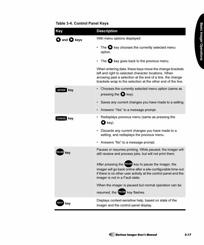
Ba
sic
Ima
ge
r Op
era
tion
s
and keys With menu options displayed:
• The key chooses the currently selected menu
option.
• The key goes back to the previous menu.
When entering data, these keys move the change brackets
left and right to selected character locations. When
arrowing past a selection at the end of a line, the change
brackets wrap to the selection at the other end of the line.
key • Chooses the currently selected menu option (same as
pressing the key).
• Saves any current changes you have made to a setting.
• Answers “Yes” to a message prompt.
key • Redisplays previous menu (same as pressing the
key).
• Discards any current changes you have made to a
setting, and redisplays the previous menu.
• Answers “No” to a message prompt.
keyPauses or resumes printing. While paused, the imager will
still receive and process jobs, but will not print them.
After pressing the key to pause the imager, the
imager will go back online after a site-configurable time-out
if there is no other user activity at the control panel and the
imager is not in a Fault state.
When the imager is paused but normal operation can be
resumed, the key flashes.
keyDisplays context-sensitive help, based on state of the
imager and the control panel display.
Table 3-4. Control Panel Keys
Key Description
� �
�
�
ENTER
�
CANCEL
�
PAUSE
PAUSE
PAUSE
HELP
Horizon Imager User’s Manual 3-17
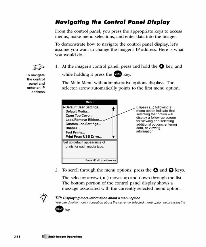
3-1
k~îáÖ~íáåÖ=íÜÉ=`çåíêçä=m~åÉä=aáëéä~ó
From the control panel, you press the appropriate keys to access menus, make menu selections, and enter data into the imager.
To demonstrate how to navigate the control panel display, let’s assume you want to change the imager’s IP address. Here is what you would do.
1. At the imager’s control panel, press and hold the key, and
while holding it press the key.
The Main Menu with administrative options displays. The selector arrow automatically points to the first menu option.
2. To scroll through the menu options, press the and keys.
The selector arrow ( � ) moves up and down through the list. The bottom portion of the control panel display shows a message associated with the currently selected menu option.
TIP: Displaying more information about a menu option
You can display more information about the currently selected menu option by pressing the
key.
8To navigate
the control
panel and
enter an IP
address
�
MENU
Menu
�Default User Settings...
Default Media...
Open Top Cover...
Load/Remove Ribbon...
Custom Job Settings...
Utilities...
Test Prints...
Print From USB Drive...
Set up default appearance of
prints for each media type.
Press MENU to exit menus
Ellipses (...) following a menu option indicate that selecting that option will display a follow-up screen for viewing and selecting additional options, entering data, or viewing information
� �
/HELP
8 Basic Imager Operations
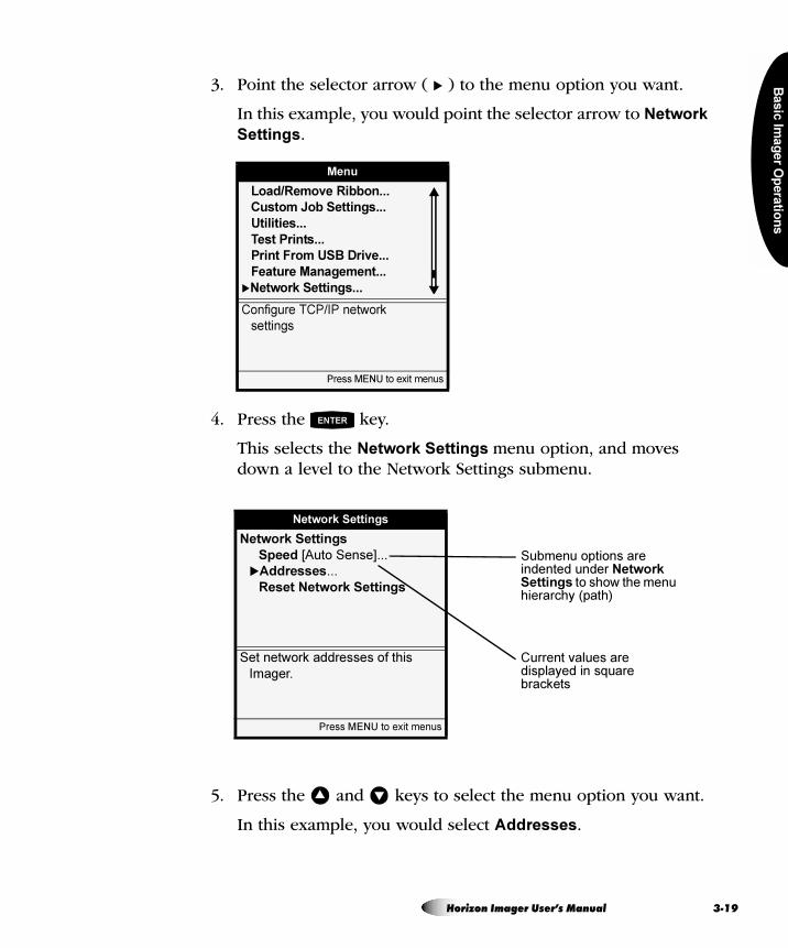
Ba
sic
Ima
ge
r Op
era
tion
s
3. Point the selector arrow ( � ) to the menu option you want.
In this example, you would point the selector arrow to Network
Settings.
4. Press the key.
This selects the Network Settings menu option, and moves down a level to the Network Settings submenu.
5. Press the and keys to select the menu option you want.
In this example, you would select Addresses.
Menu
Load/Remove Ribbon...
Custom Job Settings...
Utilities...
Test Prints...
Print From USB Drive...
Feature Management...
�Network Settings...
Configure TCP/IP network
settings
Press MENU to exit menus
ENTER
Network Settings
Network Settings
Speed [Auto Sense]...
�Addresses...
Reset Network Settings
Set network addresses of this
Imager.
Press MENU to exit menus
Submenu options are indented under Network Settings to show the menu hierarchy (path)
Current values are displayed in square brackets
� �
Horizon Imager User’s Manual 3-19
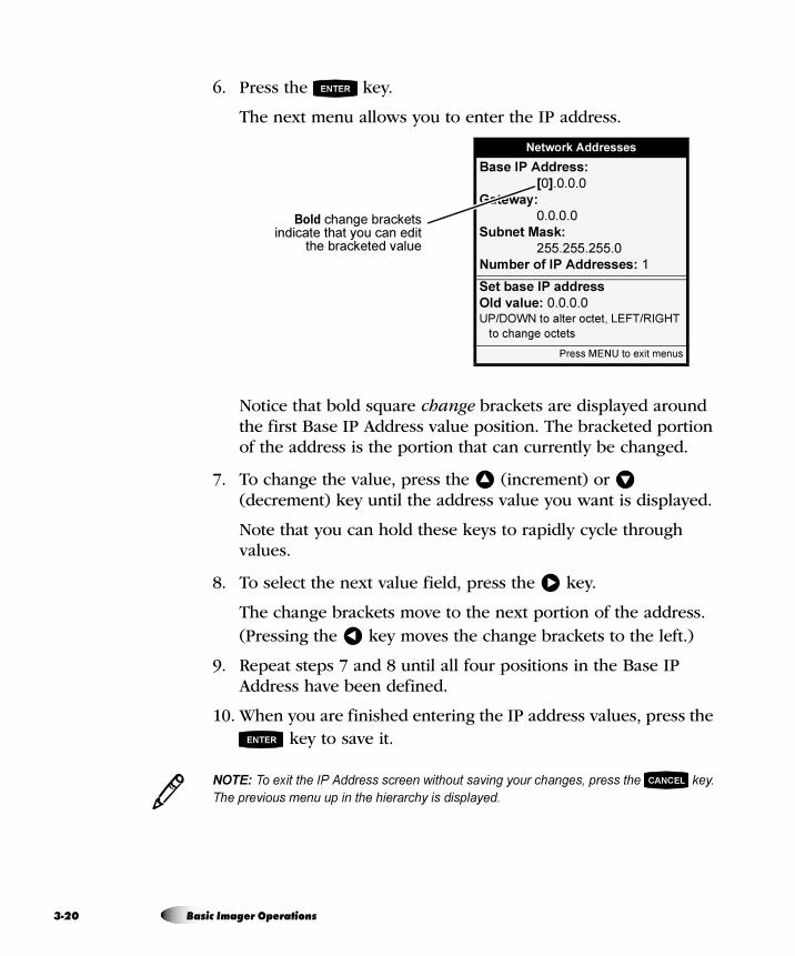
3-2
6. Press the key.
The next menu allows you to enter the IP address.
Notice that bold square change brackets are displayed around the first Base IP Address value position. The bracketed portion of the address is the portion that can currently be changed.
7. To change the value, press the (increment) or (decrement) key until the address value you want is displayed.
Note that you can hold these keys to rapidly cycle through values.
8. To select the next value field, press the key.
The change brackets move to the next portion of the address. (Pressing the key moves the change brackets to the left.)
9. Repeat steps 7 and 8 until all four positions in the Base IP Address have been defined.
10. When you are finished entering the IP address values, press the key to save it.
NOTE: To exit the IP Address screen without saving your changes, press the key.
The previous menu up in the hierarchy is displayed.
ENTER
Network Addresses
Base IP Address:
[0].0.0.0
Gateway:
0.0.0.0
Subnet Mask:
255.255.255.0
Number of IP Addresses: 1
Set base IP address
Old value: 0.0.0.0UP/DOWN to alter octet, LEFT/RIGHT
to change octets
Press MENU to exit menus
Bold change bracketsindicate that you can edit
the bracketed value
� �
�
�
ENTER
3CANCEL
0 Basic Imager Operations
Ba
sic
Ima
ge
r Op
era
tion
s
11. Press the or key to leave the Network Settings menu.
A message states that the imager will automatically reboot when
you press the key to exit the Main Menu.
12. Press the key to acknowledge the message.
13. When you are finished specifying the IP address and want to
exit the Main Menu, press the key.
Because the IP address was redefined, the imager reboots so that it can be identified properly on the network.
Cancelling Your Changes in a Screen
To exit a screen without saving your changes, press the key. Your changes are ignored and the previous menu up in the hierarchy is displayed.
Exiting the Menus
To exit the menus, press the key. You are returned to the Status screen.
pìãã~êó=çÑ=jÉåì=`çåîÉåíáçåë
The menu displays include the following conventions:
• As you move down into the menu structure, the menu path you have taken is always shown. The hierarchy of chosen menu items is sequentially indented.
• A menu option that is followed by ellipses (...) indicates that selecting that option will display a follow-up screen for viewing additional options, entering data, or viewing information.
• Current settings are displayed in square brackets. Bold square brackets indicate that you are in edit mode and can change the setting.
CANCEL �
MENU
ENTER
MENU
CANCEL
MENU
Horizon Imager User’s Manual 3-21
3-2
You must pause the imager:
• If you want to replace a supply cassette. If you pull the cassette out while the imager is picking the sheet, it could cause a jam. Or, if the sheet is already printing and you pull the cassette, it could cause an artifact to be printed on the sheet.
• If you want to temporarily stop printing.
The imager automatically enters the Pause state due to certain conditions, such as if you select the Open Top Cover function from the Utilities menu to clean the thermal print head or platen, or if a sheet jam occurs.
m~ìëáåÖ=íÜÉ=fã~ÖÉê
Press the key.
Printing pauses. If a print is in progress, the sheet completes printing before the imager pauses.
When the imager is paused, the ONLINE indicator is off, a message indicating that the imager is paused is displayed, and the key flashes (if not in a Fault state) to remind you to press it to resume normal operation once you have completed the activity.
qÜÉ=m~ìëÉ=pí~íÉ
8To pause the
imager
PAUSE
PAUSE
2 Basic Imager Operations
Ba
sic
Ima
ge
r Op
era
tion
s
oÉëìãáåÖ=mêáåíáåÖ
With the imager in the Pause state, press the key again to resume normal printing operations. If the imager has paused due to a fault state, it will go back to the active state automatically several seconds after the fault condition is
corrected, without you having to press the key.
NOTE: If you do not press the key at the completion of maintenance operations,
normal printing operations will resume automatically after a predefined time-out period if the
imager is not in a Fault state. For information about how to adjust the time-out period
(typically, one minute), refer to the Horizon Imager Technical Manual.
The Help function provides context-sensitive instructions for imager functions, parameters, and status messages. It also provides service contact information.
Help text is displayed in two ways:
• When any menu is displayed, help text relevant to the currently selected menu option is automatically displayed in the Help message area of the screen.
• By pressing the key. Pressing the key displays additional help text relative to the currently selected menu option, currently selected status message, or state of the imager. This additional help is displayed in its own Help window on top of the current screen. You dismiss this Help window by pressing
the or key.
8To resume
printing
PAUSE
PAUSE
3PAUSE
rëáåÖ=låäáåÉ=eÉäé
HELP HELP
HELP CANCEL
Horizon Imager User’s Manual 3-23

3-2
4 Basic Imager Operations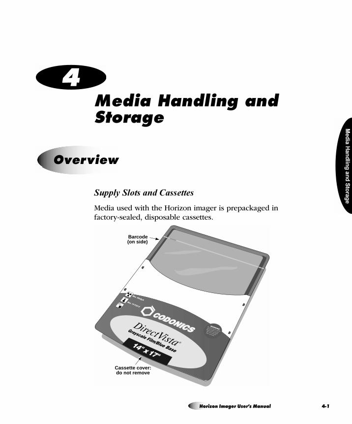
Med
ia H
an
dlin
g a
nd
Sto
rag
e
= QjÉÇá~=e~åÇäáåÖ=~åÇ=píçê~ÖÉ
Supply Slots and Cassettes
Media used with the Horizon imager is prepackaged in factory-sealed, disposable cassettes.
lîÉêîáÉï
Barcode(on side)
Cassette cover:do not remove
Horizon Imager User’s Manual 4-1
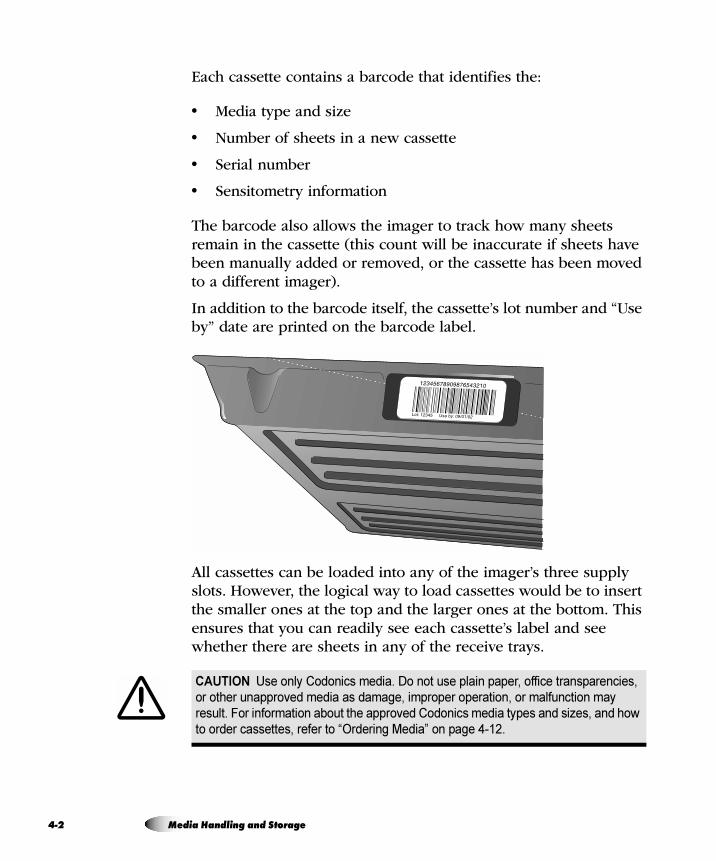
4-2
Each cassette contains a barcode that identifies the:
• Media type and size
• Number of sheets in a new cassette
• Serial number
• Sensitometry information
The barcode also allows the imager to track how many sheets remain in the cassette (this count will be inaccurate if sheets have been manually added or removed, or the cassette has been moved to a different imager).
In addition to the barcode itself, the cassette’s lot number and “Use by” date are printed on the barcode label.
All cassettes can be loaded into any of the imager’s three supply slots. However, the logical way to load cassettes would be to insert the smaller ones at the top and the larger ones at the bottom. This ensures that you can readily see each cassette’s label and see whether there are sheets in any of the receive trays.
CAUTION Use only Codonics media. Do not use plain paper, office transparencies,
or other unapproved media as damage, improper operation, or malfunction may
result. For information about the approved Codonics media types and sizes, and how
to order cassettes, refer to “Ordering Media” on page 4-12.
Media Handling and Storage
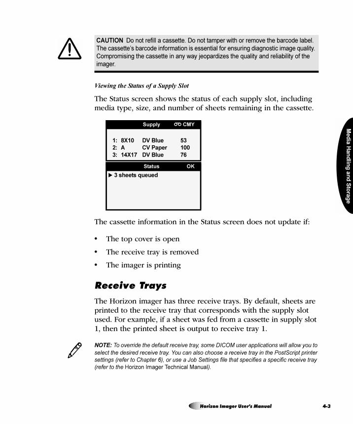
Med
ia H
an
dlin
g a
nd
Sto
rag
e
Viewing the Status of a Supply Slot
The Status screen shows the status of each supply slot, including media type, size, and number of sheets remaining in the cassette.
The cassette information in the Status screen does not update if:
• The top cover is open
• The receive tray is removed
• The imager is printing
oÉÅÉáîÉ=qê~óë
The Horizon imager has three receive trays. By default, sheets are printed to the receive tray that corresponds with the supply slot used. For example, if a sheet was fed from a cassette in supply slot 1, then the printed sheet is output to receive tray 1.
NOTE: To override the default receive tray, some DICOM user applications will allow you to
select the desired receive tray. You can also choose a receive tray in the PostScript printer
settings (refer to Chapter 6), or use a Job Settings file that specifies a specific receive tray
(refer to the Horizon Imager Technical Manual).
CAUTION Do not refill a cassette. Do not tamper with or remove the barcode label.
The cassette’s barcode information is essential for ensuring diagnostic image quality.
Compromising the cassette in any way jeopardizes the quality and reliability of the
imager.
Supply CMY
1: 8X10 DV Blue 53
2: A CV Paper 100
3: 14X17 DV Blue 76
Status OK
� 3 sheets queued
3
Horizon Imager User’s Manual 4-3
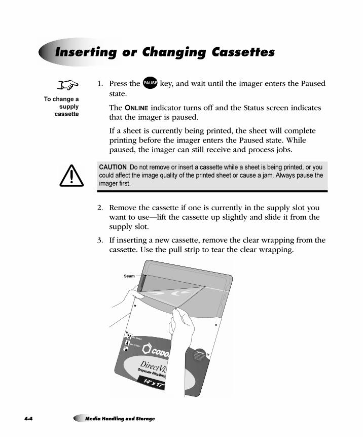
4-4
1. Press the key, and wait until the imager enters the Paused state.
The ONLINE indicator turns off and the Status screen indicates that the imager is paused.
If a sheet is currently being printed, the sheet will complete printing before the imager enters the Paused state. While paused, the imager can still receive and process jobs.
2. Remove the cassette if one is currently in the supply slot you want to use—lift the cassette up slightly and slide it from the supply slot.
3. If inserting a new cassette, remove the clear wrapping from the cassette. Use the pull strip to tear the clear wrapping.
fåëÉêíáåÖ=çê=`Ü~åÖáåÖ=`~ëëÉííÉë
CAUTION Do not remove or insert a cassette while a sheet is being printed, or you
could affect the image quality of the printed sheet or cause a jam. Always pause the
imager first.
8To change a
supply
cassette
PAUSE
Seam
Media Handling and Storage
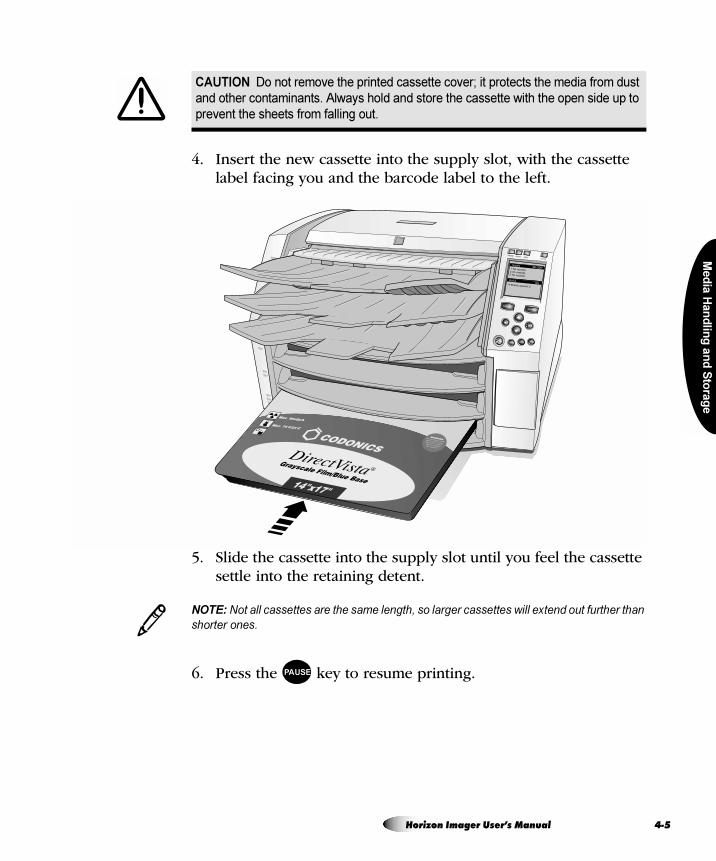
Med
ia H
an
dlin
g a
nd
Sto
rag
e
4. Insert the new cassette into the supply slot, with the cassette label facing you and the barcode label to the left.
5. Slide the cassette into the supply slot until you feel the cassette settle into the retaining detent.
NOTE: Not all cassettes are the same length, so larger cassettes will extend out further than
shorter ones.
6. Press the key to resume printing.
CAUTION Do not remove the printed cassette cover; it protects the media from dust
and other contaminants. Always hold and store the cassette with the open side up to
prevent the sheets from falling out.
3
PAUSE
Horizon Imager User’s Manual 4-5
4-6
When a print job is sent, the media type and size are specified in the print job.
• If the specified media type and size are supported by the imager and the required supply cassette is not loaded, the imager will display a message on the Status screen prompting you to insert the appropriate cassette or ribbon.
• If the specified media type and size are not supported by the imager, the default type and size is used. Refer to “Changing the Default Media Type and Size” on page 8-3 for more information about setting the default type and size.
aÉíÉêãáåáåÖ=tÜáÅÜ=`~ëëÉííÉ=íç=rëÉ
Media Handling and Storage
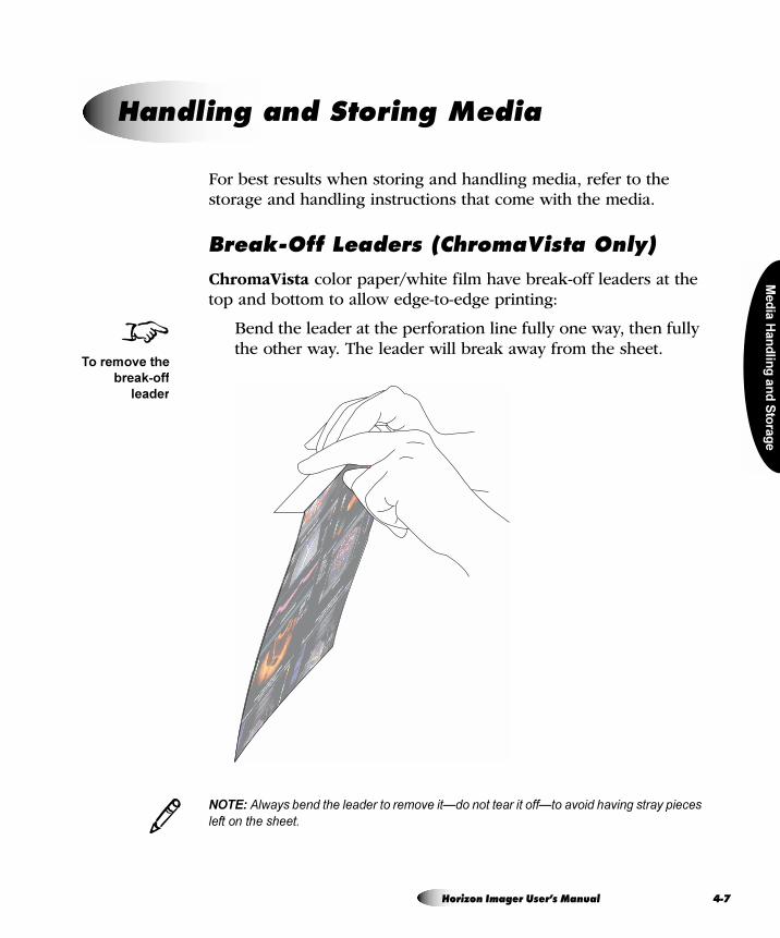
Med
ia H
an
dlin
g a
nd
Sto
rag
e
For best results when storing and handling media, refer to the storage and handling instructions that come with the media.
_êÉ~âJlÑÑ=iÉ~ÇÉêë=E`Üêçã~sáëí~=låäóF
ChromaVista color paper/white film have break-off leaders at the top and bottom to allow edge-to-edge printing:
Bend the leader at the perforation line fully one way, then fully the other way. The leader will break away from the sheet.
NOTE: Always bend the leader to remove it—do not tear it off—to avoid having stray pieces
left on the sheet.
e~åÇäáåÖ=~åÇ=píçêáåÖ=jÉÇá~
8To remove the
break-off
leader
3
Horizon Imager User’s Manual 4-7
4-8
When the ribbon on the ribbon spools has been consumed and needs to be changed:
• The imager enters the Alert state.
• The word “OUT” flashes in the Status screen title bar next to the ribbon symbol ( ) instead of displaying the ribbon type.
• A message indicating that a new ribbon needs to be loaded is displayed in the Status window.
1. Press the key.
The Main Menu displays.
2. Select the Load/Remove Ribbon menu option.
After selecting this option:
• The imager pauses, first completing the sheet if one is currently printing.
• The ribbon supply spool inside the imager rises.
• After up to a minute to allow the thermal print head to cool, the imager cover pops partially open.
3. Lift the cover all the way open, and locate the ribbon spools.
`Ü~åÖáåÖ=íÜÉ=oáÄÄçå=E`Üêçã~sáëí~F
WARNING With the imager cover open, touch only those internal components
that are colored green (refer to the figure on page xxxii). Remove rings, ties,
jewelry, and other items, and tie back hair, so that they do not fall into or get
caught in the imager.
8To change the
color ribbon
MENU
Media Handling and Storage
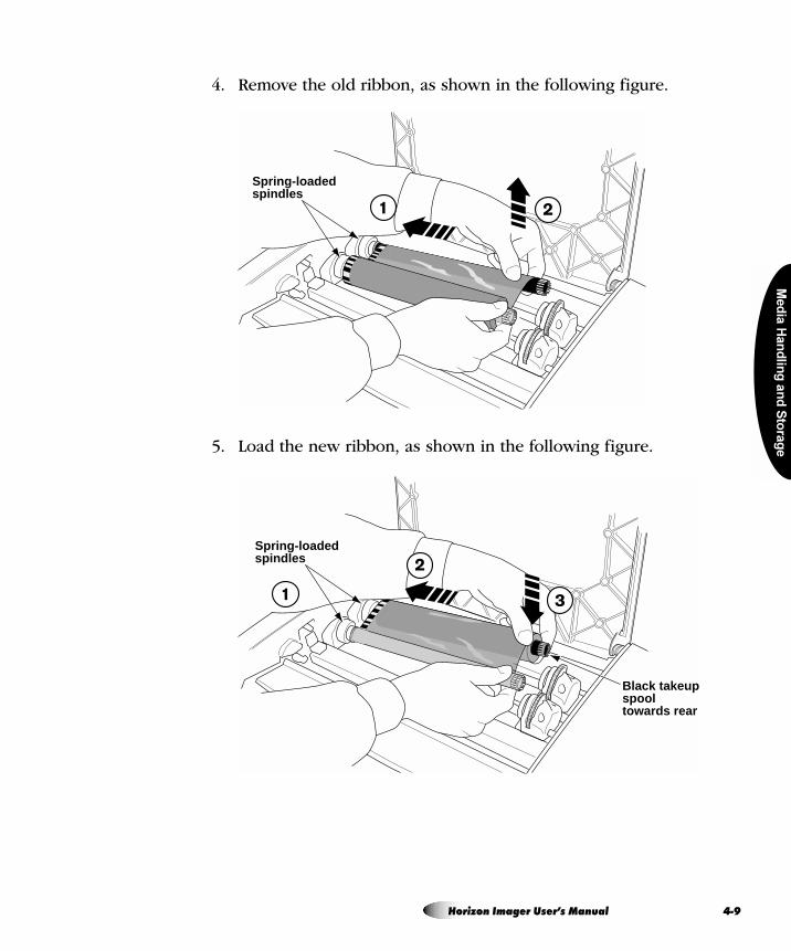
Med
ia H
an
dlin
g a
nd
Sto
rag
e
4. Remove the old ribbon, as shown in the following figure.
5. Load the new ribbon, as shown in the following figure.
Spring-loaded spindles
Spring-loaded spindles
Black takeupspooltowards rear
Horizon Imager User’s Manual 4-9
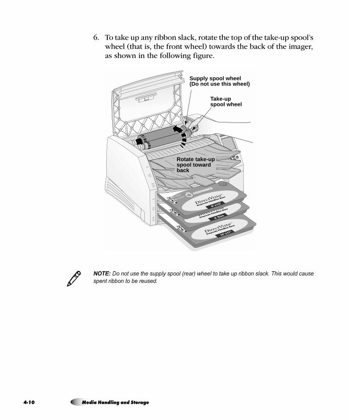
4-1
6. To take up any ribbon slack, rotate the top of the take-up spool’s wheel (that is, the front wheel) towards the back of the imager, as shown in the following figure.
NOTE: Do not use the supply spool (rear) wheel to take up ribbon slack. This would cause
spent ribbon to be reused.
Take-upspool wheel
Rotate take-upspool towardback
Supply spool wheel(Do not use this wheel)
3
0 Media Handling and Storage
Med
ia H
an
dlin
g a
nd
Sto
rag
e
7. When you are finished changing the ribbon, close the top cover.
After several seconds, the imager will leave the paused state and resume printing.
TIP: You can leave the ribbon in the imager
The only time you need to remove the ribbon is if you are cleaning internal components or
the ribbon has been consumed. Otherwise, you can leave the ribbon in the imager, even
when printing to DirectVista grayscale media.
CAUTION Used ribbon retains the negative of the color images that were printed
using that ribbon. If you are required to ensure patient confidentiality and privacy, the
ribbon should be destroyed.
/
Horizon Imager User’s Manual 4-11
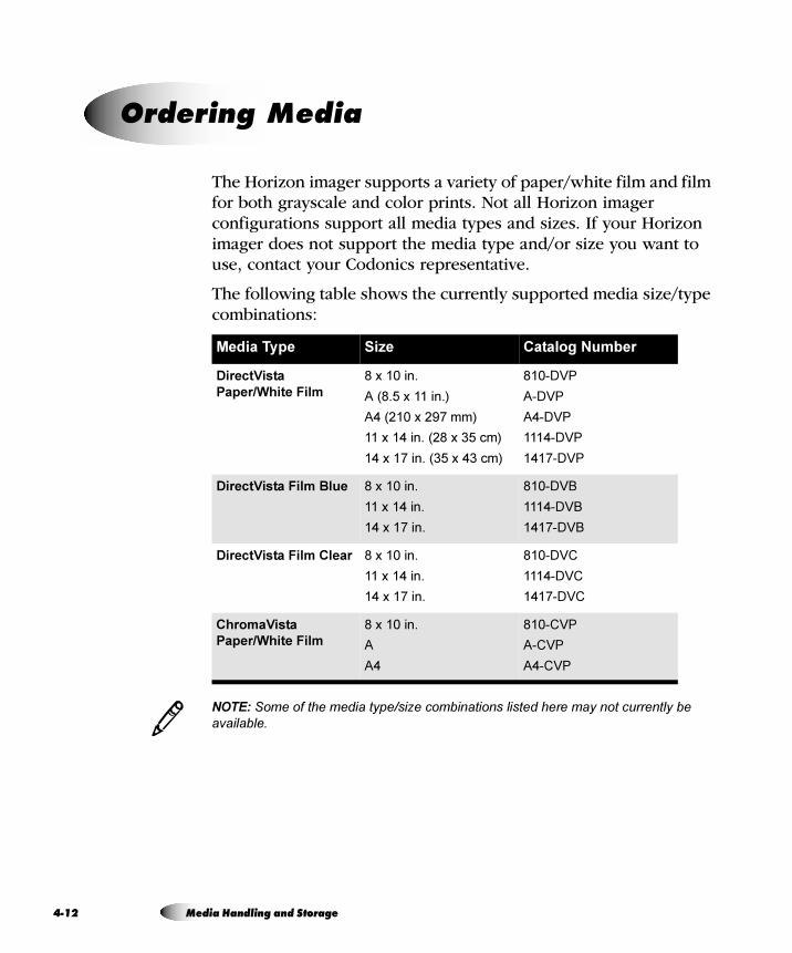
4-1
The Horizon imager supports a variety of paper/white film and film for both grayscale and color prints. Not all Horizon imager configurations support all media types and sizes. If your Horizon imager does not support the media type and/or size you want to use, contact your Codonics representative.
The following table shows the currently supported media size/type combinations:
NOTE: Some of the media type/size combinations listed here may not currently be available.
lêÇÉêáåÖ=jÉÇá~
Media Type Size Catalog Number
DirectVista
Paper/White Film
8 x 10 in.
A (8.5 x 11 in.)
A4 (210 x 297 mm)
11 x 14 in. (28 x 35 cm)
14 x 17 in. (35 x 43 cm)
810-DVP
A-DVP
A4-DVP
1114-DVP
1417-DVP
DirectVista Film Blue 8 x 10 in.
11 x 14 in.
14 x 17 in.
810-DVB
1114-DVB
1417-DVB
DirectVista Film Clear 8 x 10 in.
11 x 14 in.
14 x 17 in.
810-DVC
1114-DVC
1417-DVC
ChromaVista
Paper/White Film
8 x 10 in.
A
A4
810-CVP
A-CVP
A4-CVP
3
2 Media Handling and Storage
Med
ia H
an
dlin
g a
nd
Sto
rag
e
DirectVista grayscale media is orderable by the case, at 5 cassettes per case, with 100 sheets of film per cassette and 80 sheets of media per cassette.
ChromaVista color media is available in packages that contain 2 media cassettes and 1 color ribbon. ChromaVista cassettes contain 50 sheets of paper/white film.
To order media, contact Codonics at:
Phone: +1.440.243.1198
Toll Free: 800.444.1198 (USA only)
Fax: +1.440.243.1334
Web Site: www.codonics.com
Horizon Imager User’s Manual 4-13

Prin
ting
from
DIC
OM
Ap
plic
atio
ns
= RmêáåíáåÖ=Ñêçã=af`lj=^ééäáÅ~íáçåë
The printing procedures covered in this chapter assume that the DICOM support option is installed in your Horizon imager and that you are sending print jobs from a DICOM application. DICOM applications typically run on an imaging device or on an image viewing workstation.
NOTE: If you are running DICOM Lite on the imager and see connection errors at the
console or workstation from which you are sending print jobs, you may require more
connections than DICOM Lite provides. Contact Codonics technical support for assistance
(refer to “Contacting Technical Support” on page 12-30).
DICOM (Digital Imaging and COmmunications in Medicine) is the industry standard for transferring images and other medical information from radiology, cardiology, ophthalmology, endoscopy, mammography, and many other medical modalities with other devices. DICOM provides a common platform so that systems from various manufacturers can transfer images and related information.
3
fåíêçÇìÅíáçå=íç=af`lj
Horizon Imager User’s Manual 5-1
5-2
For example, workstations, CT scanners, MR imagers, film digitizers, shared archives, film imagers, and host computers made by different vendors and located at the same or different sites can “talk to one another” by means of DICOM across an “open-system” network.
A device or application is said to be DICOM-compliant when the manufacturer declares that its device will follow the rules defined in the DICOM standard for its device type. The Horizon imager is DICOM Print Service Class-compliant. It is anticipated that most print jobs will be sent to the Horizon imager from DICOM Print Service Class-compliant imaging devices or image viewing workstations.
For more information about DICOM, visit the official web site—medical.nema.org. Additional information is available at the web site of the Radiological Society of North America, Inc. (www.rsna.org).
af`lj=`çåÑçêã~åÅÉ=pí~íÉãÉåí
Vendors who claim that their device or application conforms to DICOM must publish a conformance statement that describes how it conforms. Most devices or applications will not support all of the features of a particular DICOM service. Whether each feature of the service is supported or not would be included in the conformance statement.
The vendor or person responsible for implementing the Horizon imager will study the conformance statements for the Horizon imager and for any other DICOM devices or applications that will be sending print jobs to it. By examining these conformance statements, the implementor will determine exactly what DICOM Print Service Class Provider options the Horizon imager supports. The implementor will also be able to tell if the other devices will be compatible with the imager.
The Horizon imager conformance statement is available on the Codonics web site (www.codonics.com). It can also be mailed or faxed to you on request.
Printing from DICOM Applications
Prin
ting
from
DIC
OM
Ap
plic
atio
ns
eçï=~=af`lj=mêáåí=gçÄ=fë=mêçÅÉëëÉÇ
A DICOM print job transaction consists of two participants:
• The device making the print request. This can be an imaging device (such as an MRI or ultrasound system) or an image viewing workstation at which an image is being displayed. In DICOM terms, this device is referred to as a Print Service Class User.
• The device that will service the print request and print the image on a sheet—for example, the Horizon imager. In DICOM terms, this device is referred to as a Print Service Class Provider.
To identify the DICOM Print Service Class User application, the application is assigned a unique name—the Calling AE (application entity) Title.
To identify a Print Service Class Provider application, it also is assigned a unique name—the Called AE Title.
Horizon Imager User’s Manual 5-3
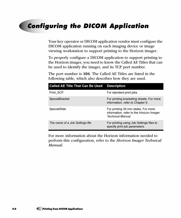
5-4
Your key operator or DICOM application vendor must configure the DICOM application running on each imaging device or image viewing workstation to support printing to the Horizon imager.
To properly configure a DICOM application to support printing to the Horizon imager, you need to know the Called AE Titles that can be used to identify the imager, and its TCP port number.
The port number is 104. The Called AE Titles are listed in the following table, which also describes how they are used.
For more information about the Horizon information needed to perform this configuration, refer to the Horizon Imager Technical Manual.
`çåÑáÖìêáåÖ=íÜÉ=af`lj=^ééäáÅ~íáçå
Called AE Title That Can Be Used Description
Print_SCP For standard print jobs.
SpecialBracket For printing bracketing sheets. For more
information, refer to Chapter 9.
SpecialSlide For printing 35-mm slides. For more
information, refer to the Horizon Imager Technical Manual.
The name of a Job Settings file For printing using Job Settings files to
specify print job parameters.
Printing from DICOM Applications
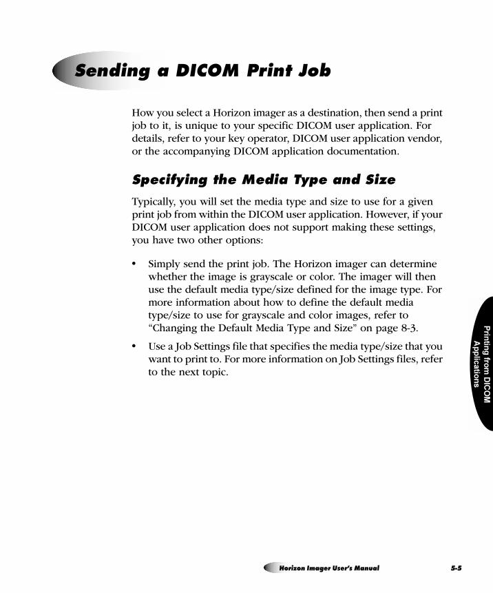
Prin
ting
from
DIC
OM
Ap
plic
atio
ns
How you select a Horizon imager as a destination, then send a print job to it, is unique to your specific DICOM user application. For details, refer to your key operator, DICOM user application vendor, or the accompanying DICOM application documentation.
péÉÅáÑóáåÖ=íÜÉ=jÉÇá~=qóéÉ=~åÇ=páòÉ
Typically, you will set the media type and size to use for a given print job from within the DICOM user application. However, if your DICOM user application does not support making these settings, you have two other options:
• Simply send the print job. The Horizon imager can determine whether the image is grayscale or color. The imager will then use the default media type/size defined for the image type. For more information about how to define the default media type/size to use for grayscale and color images, refer to “Changing the Default Media Type and Size” on page 8-3.
• Use a Job Settings file that specifies the media type/size that you want to print to. For more information on Job Settings files, refer to the next topic.
pÉåÇáåÖ=~=af`lj=mêáåí=gçÄ
Horizon Imager User’s Manual 5-5
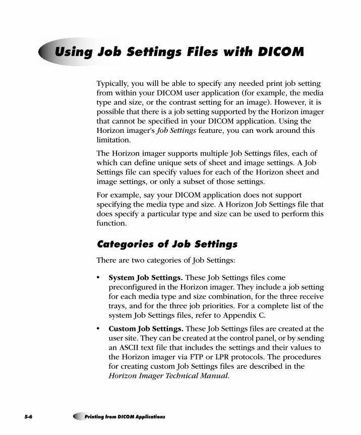
5-6
Typically, you will be able to specify any needed print job setting from within your DICOM user application (for example, the media type and size, or the contrast setting for an image). However, it is possible that there is a job setting supported by the Horizon imager that cannot be specified in your DICOM application. Using the Horizon imager’s Job Settings feature, you can work around this limitation.
The Horizon imager supports multiple Job Settings files, each of which can define unique sets of sheet and image settings. A Job Settings file can specify values for each of the Horizon sheet and image settings, or only a subset of those settings.
For example, say your DICOM application does not support specifying the media type and size. A Horizon Job Settings file that does specify a particular type and size can be used to perform this function.
`~íÉÖçêáÉë=çÑ=gçÄ=pÉííáåÖë
There are two categories of Job Settings:
• System Job Settings. These Job Settings files come preconfigured in the Horizon imager. They include a job setting for each media type and size combination, for the three receive trays, and for the three job priorities. For a complete list of the system Job Settings files, refer to Appendix C.
• Custom Job Settings. These Job Settings files are created at the user site. They can be created at the control panel, or by sending an ASCII text file that includes the settings and their values to the Horizon imager via FTP or LPR protocols. The procedures for creating custom Job Settings files are described in the Horizon Imager Technical Manual.
rëáåÖ=gçÄ=pÉííáåÖë=cáäÉë=ïáíÜ=af`lj
Printing from DICOM Applications
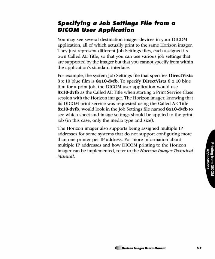
Prin
ting
from
DIC
OM
Ap
plic
atio
ns
péÉÅáÑóáåÖ=~=gçÄ=pÉííáåÖë=cáäÉ=Ñêçã=~=af`lj=rëÉê=^ééäáÅ~íáçå
You may see several destination imager devices in your DICOM application, all of which actually print to the same Horizon imager. They just represent different Job Settings files, each assigned its own Called AE Title, so that you can use various job settings that are supported by the imager but that you cannot specify from within the application’s standard interface.
For example, the system Job Settings file that specifies DirectVista 8 x 10 blue film is 8x10-dvfb. To specify DirectVista 8 x 10 blue film for a print job, the DICOM user application would use 8x10-dvfb as the Called AE Title when starting a Print Service Class session with the Horizon imager. The Horizon imager, knowing that its DICOM print service was requested using the Called AE Title 8x10-dvfb, would look in the Job Settings file named 8x10-dvfb to see which sheet and image settings should be applied to the print job (in this case, only the media type and size).
The Horizon imager also supports being assigned multiple IP addresses for some systems that do not support configuring more than one printer per IP address. For more information about multiple IP addresses and how DICOM printing to the Horizon imager can be implemented, refer to the Horizon Imager Technical Manual.
Horizon Imager User’s Manual 5-7
5-8
eáÉê~êÅÜó=çÑ=pÉííáåÖë=rëÉÇ=Äó=íÜÉ=eçêáòçå=fã~ÖÉê
For DICOM print jobs, the Horizon Imager uses the following sequence to determine the values for sheet and image settings to use when printing a sheet:
1. Looks in the specified Job Settings file.
2. For any sheet or image settings not specified in the Job Settings file, looks in the DICOM print session information (for settings defined within the DICOM user application).
3. For any sheet or image settings not specified in the Job Settings file or DICOM print session information, uses the imager’s default settings. For more information about the imager’s default settings, refer to Chapter 8.
For more information on the hierarchy of settings, refer to the Horizon imager’s DICOM Conformance Statement, and to the Horizon Imager Technical Manual.
Printing from DICOM Applications
Prin
ting
via
Po
stS
crip
t
= SmêáåíáåÖ=îá~=mçëípÅêáéí
The printing procedures covered in this chapter assume that:
• The PostScript support option is installed in your Horizon imager.
• The Horizon imager has been configured as a Windows or Macintosh desktop printer on your workstation using the Horizon PostScript print driver.
• You are sending print jobs from a Windows (Windows 98, Me, NT 4.0, 2000, or XP) or Macintosh (OS 8, 9, or X) application.
• You are familiar, in general, with how to print from Windows or Macintosh applications to a desktop printer.
Complete instructions for adding a Horizon imager as a desktop printer are provided in the Horizon PostScript Driver Technical Briefs, available in PDF format on the Horizon PostScript Drivers CD-ROM.
For sending PostScript files from UNIX or Linux, refer to the Horizon Imager Technical Manual.
Horizon Imager User’s Manual 6-1
6-2
PostScript printing technology was developed to provide consistent, predictable printing from every major computer platform to any printing device that supports it.
PostScript is software that tells an output device, such as a printer, how to print fonts and graphic elements on a page. As such, it acts as a translation program between a workstation application and the printer.
The basic workflow of a PostScript print job is as follows:
1. When you execute the Print function from within your workstation application, a PostScript print driver creates a PostScript language file.
This file contains PostScript commands that describe the page to be printed, the size and style of fonts and graphics, where they should be placed on the page, and color information.
2. The PostScript language file is sent to the output device.
3. A raster image processor (RIP) in the output device processes the file, translating the commands into an array of pixels—referred to as a raster image—that recreate the intended image of the entire page.
4. The raster image data is sent to the device’s print engine, which in turn prints the pixels on the page media.
There have been three PostScript technologies released since its inception—levels 1, 2, and, the most recent version, 3. The Horizon imager supports all three levels.
fåíêçÇìÅíáçå=íç=mçëípÅêáéí
Printing via PostScript
Prin
ting
via
Po
stS
crip
t
eáÉê~êÅÜó=çÑ=m~ê~ãÉíÉê=pÉííáåÖë=rëÉÇ=Äó=íÜÉ=eçêáòçå=fã~ÖÉê
For PostScript print jobs, the Horizon Imager uses the following sequence to determine the values for sheet and image parameters to use when printing a sheet:
1. Uses the parameter settings in the PostScript print job information.
2. For any sheet or image parameters not specified in the PostScript print job information, uses the imager’s default settings for those parameters. For more information about the imager’s default settings, refer to Chapter 8.
NOTE: You can access any of the Horizon imager’s sheet and image parameters from a
Windows or Macintosh application when sending a print job. Therefore, using Job Settings
files with PostScript is not necessary and so is not supported.
péÉÅáÑóáåÖ=íÜÉ=jÉÇá~=qóéÉ=~åÇ=páòÉ
When sending a print job via PostScript, you specify the media size and type using PostScript parameters. How you access these parameters, and what their defaults are set to, differ depending on which operating system you are using. For more information, refer to the appropriate topic in this chapter.
3
Horizon Imager User’s Manual 6-3
6-4
Once the Horizon imager is set up as a Windows printer on your workstation (which is described in several Horizon PostScript Technical Briefs, one for each type of Windows system), you can send images to it for printing from any Windows application.
Typically, when you invoke the Print function from within the application, a Print dialog box displays. From this dialog box, you can select the Horizon imager as the print destination, if it has not already been set as your default printer.
péÉÅáÑóáåÖ=eçêáòçå=mçëípÅêáéí=m~ê~ãÉíÉêë
When the Horizon imager is added as a Windows printer, a default set of print job, sheet, and image parameter settings is defined for it. However, from the Print dialog box, you can change any of the parameters’ settings. Table 6-1 on page 6-6 describes each of the Horizon PostScript parameters that can be changed. For more information about print job, sheet, and image parameters, refer to Appendix D and to the Horizon Imager Technical Manual.
For instructions about how to change Horizon PostScript parameter settings:
• For Windows 98 and Me, refer to “Changing Horizon PostScript Parameters—Windows 98 and Me” on page 6-9.
• For Windows NT, refer to “Changing Horizon PostScript Parameters—Windows NT” on page 6-12.
• For Windows 2000 and XP, refer to “Changing Horizon PostScript Parameters—Windows 2000 and XP” on page 6-15.
mêáåíáåÖ=Ñêçã=táåÇçïë=^ééäáÅ~íáçåë
Printing via PostScript
Prin
ting
via
Po
stS
crip
t
kçíÉë=^Äçìí=`Ü~åÖáåÖ=mçëípÅêáéí=m~ê~ãÉíÉêë
• There are other, non-Horizon-related parameters included in the set of available PostScript print parameters. Because unpredictable results may occur, it is recommended that you change the defaults for only those Horizon imager parameters listed in Table 6-1 on page 6-6.
• Some of the “Allowed Values” shown in Table 6-1 may depend on available imager options and thus may not appear on some systems.
• Settings made at print time via the Print dialog boxes will take precedence over settings made at the imager. Note, however, that the Use Printer Default or Use Current Setting in the Printer setting can be chosen for many of the parameters in the Print dialog box.
Horizon Imager User’s Manual 6-5
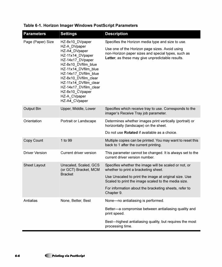
6-6
Table 6-1. Horizon Imager Windows PostScript Parameters
Parameters Settings Description
Page (Paper) Size HZ-8x10_DVpaper
HZ-A_DVpaper
HZ-A4_DVpaper
HZ-11x14_DVpaper
HZ-14x17_DVpaper
HZ-8x10_DVfilm_blue
HZ-11x14_DVfilm_blue
HZ-14x17_DVfilm_blue
HZ-8x10_DVfilm_clear
HZ-11x14_DVfilm_clear
HZ-14x17_DVfilm_clear
HZ-8x10_CVpaper
HZ-A_CVpaper
HZ-A4_CVpaper
Specifies the Horizon media type and size to use.
Use one of the Horizon page sizes. Avoid using
non-Horizon paper sizes and special types, such as
Letter, as these may give unpredictable results.
Output Bin Upper, Middle, Lower Specifies which receive tray to use. Corresponds to the
imager’s Receive Tray job parameter.
Orientation Portrait or Landscape Determines whether images print vertically (portrait) or
horizontally (landscape) on the sheet.
Do not use Rotated if available as a choice.
Copy Count 1 to 99 Multiple copies can be printed. You may want to reset this
back to 1 after the current printing.
Driver Version Current driver version This parameter cannot be changed. It is always set to the
current driver version number.
Sheet Layout Unscaled, Scaled, GCS
(or GCT) Bracket, MCM
Bracket
Specifies whether the image will be scaled or not, or
whether to print a bracketing sheet.
Use Unscaled to print the image at original size. Use
Scaled to print the image scaled to the media size.
For information about the bracketing sheets, refer to
Chapter 9.
Antialias None, Better, Best None—no antialiasing is performed.
Better—a compromise between antialiasing quality and
print speed.
Best—highest antialiasing quality, but requires the most
processing time.
Printing via PostScript
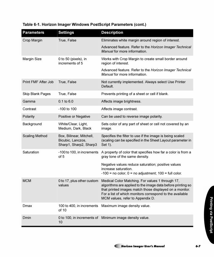
Prin
ting
via
Po
stS
crip
t
Crop Margin True, False Eliminates white margin around region of interest.
Advanced feature. Refer to the Horizon Imager Technical Manual for more information.
Margin Size 0 to 50 (pixels), in
increments of 5
Works with Crop Margin to create small border around
region of interest.
Advanced feature. Refer to the Horizon Imager Technical Manual for more information.
Print FMF After Job True, False Not currently implemented. Always select Use Printer
Default.
Skip Blank Pages True, False Prevents printing of a sheet or cell if blank.
Gamma 0.1 to 6.0 Affects image brightness.
Contrast -100 to 100 Affects image contrast.
Polarity Positive or Negative Can be used to reverse image polarity.
Background White/Clear, Light,
Medium, Dark, Black
Sets color of any part of sheet or cell not covered by an
image.
Scaling Method Box, Bilinear, Mitchell,
Bicubic, Lanczos,
Sharp1, Sharp2, Sharp3
Specifies the filter to use if the image is being scaled
(scaling can be specified in the Sheet Layout parameter in
Set 1).
Saturation -100 to 100, in increments
of 5
A property of color that specifies how far a color is from a
gray tone of the same density.
Negative values reduce saturation; positive values
increase saturation.
-100 = no color; 0 = no adjustment; 100 = full color.
MCM 0 to 17, plus other custom
values
Medical Color Matching. For values 1 through 17,
algorithms are applied to the image data before printing so
that printed images match those displayed on a monitor.
For a list of which monitors correspond to the available
MCM values, refer to Appendix D.
Dmax 100 to 400, in increments
of 10
Maximum image density value.
Dmin 0 to 100, in increments of
10
Minimum image density value.
Table 6-1. Horizon Imager Windows PostScript Parameters (cont.)
Parameters Settings Description
Horizon Imager User’s Manual 6-7
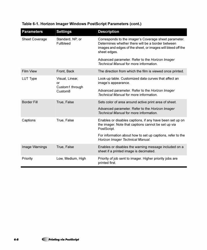
6-8
Sheet Coverage Standard, NP, or
Fullbleed
Corresponds to the imager’s Coverage sheet parameter.
Determines whether there will be a border between
images and edges of the sheet, or images will bleed off the
sheet edges.
Advanced parameter. Refer to the Horizon Imager Technical Manual for more information.
Film View Front, Back The direction from which the film is viewed once printed.
LUT Type Visual, Linear,
or
Custom1 through
Custom8
Look-up table. Customized data curves that affect an
image’s appearance.
Advanced parameter. Refer to the Horizon Imager Technical Manual for more information.
Border Fill True, False Sets color of area around active print area of sheet.
Advanced parameter. Refer to the Horizon Imager Technical Manual for more information.
Captions True, False Enables or disables captions, if any have been set up on
the imager. Note that captions cannot be set up via
PostScript.
For information about how to set up captions, refer to the
Horizon Imager Technical Manual.
Image Warnings True, False Enables or disables the warning message included on a
sheet if a printed image is decimated.
Priority Low, Medium, High Priority of job sent to imager. Higher priority jobs are
printed first.
Table 6-1. Horizon Imager Windows PostScript Parameters (cont.)
Parameters Settings Description
Printing via PostScript
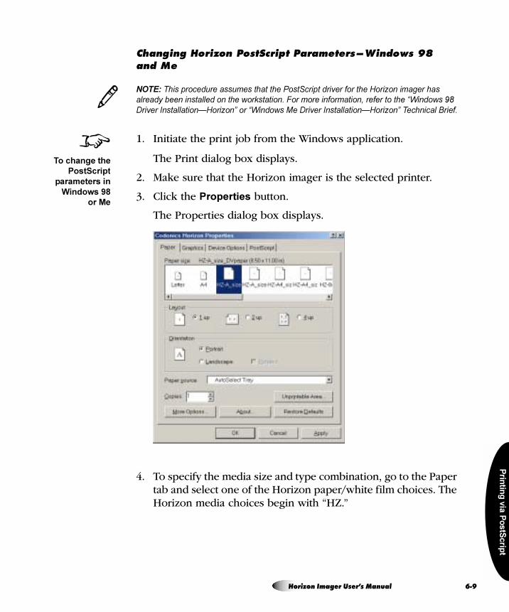
Prin
ting
via
Po
stS
crip
t
`Ü~åÖáåÖ=eçêáòçå=mçëípÅêáéí=m~ê~ãÉíÉêëÔtáåÇçïë VU=~åÇ jÉ
NOTE: This procedure assumes that the PostScript driver for the Horizon imager has
already been installed on the workstation. For more information, refer to the “Windows 98
Driver Installation—Horizon” or “Windows Me Driver Installation—Horizon” Technical Brief.
1. Initiate the print job from the Windows application.
The Print dialog box displays.
2. Make sure that the Horizon imager is the selected printer.
3. Click the Properties button.
The Properties dialog box displays.
4. To specify the media size and type combination, go to the Paper tab and select one of the Horizon paper/white film choices. The Horizon media choices begin with “HZ.”
3
8To change the
PostScript
parameters in
Windows 98
or Me
Horizon Imager User’s Manual 6-9
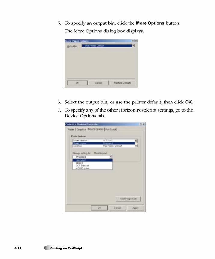
6-1
5. To specify an output bin, click the More Options button.
The More Options dialog box displays.
6. Select the output bin, or use the printer default, then click OK.
7. To specify any of the other Horizon PostScript settings, go to the Device Options tab.
0 Printing via PostScript

Prin
ting
via
Po
stS
crip
t
8. To change a parameter’s setting, select the parameter from the Printer Features list.
The available choices are listed in the Change setting for drop-down list.
9. Select the desired setting from the Change setting for list.
10. When you are done changing settings, click OK to save your changes.
The settings you have saved will be in effect for the current session of the application from which you are printing. If you open a new session of the application or print from a different application, the parameters revert to their default settings.
Horizon Imager User’s Manual 6-11
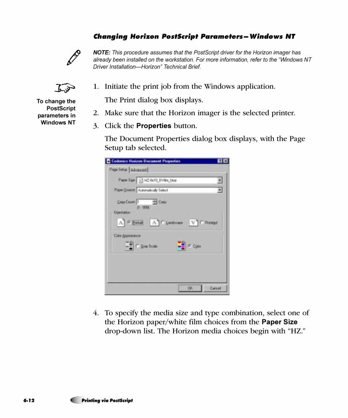
6-1
`Ü~åÖáåÖ=eçêáòçå=mçëípÅêáéí=m~ê~ãÉíÉêëÔtáåÇçïë kq
NOTE: This procedure assumes that the PostScript driver for the Horizon imager has
already been installed on the workstation. For more information, refer to the “Windows NT
Driver Installation—Horizon” Technical Brief.
1. Initiate the print job from the Windows application.
The Print dialog box displays.
2. Make sure that the Horizon imager is the selected printer.
3. Click the Properties button.
The Document Properties dialog box displays, with the Page Setup tab selected.
4. To specify the media size and type combination, select one of the Horizon paper/white film choices from the Paper Size drop-down list. The Horizon media choices begin with “HZ.”
3
8To change the
PostScript
parameters in
Windows NT
2 Printing via PostScript
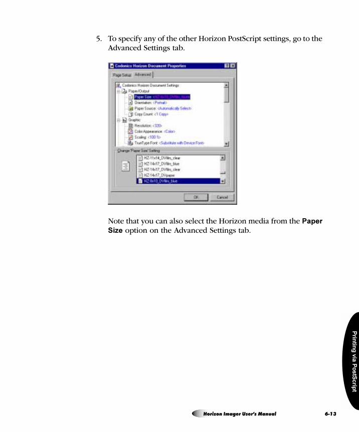
Prin
ting
via
Po
stS
crip
t
5. To specify any of the other Horizon PostScript settings, go to the Advanced Settings tab.
Note that you can also select the Horizon media from the Paper
Size option on the Advanced Settings tab.
Horizon Imager User’s Manual 6-13
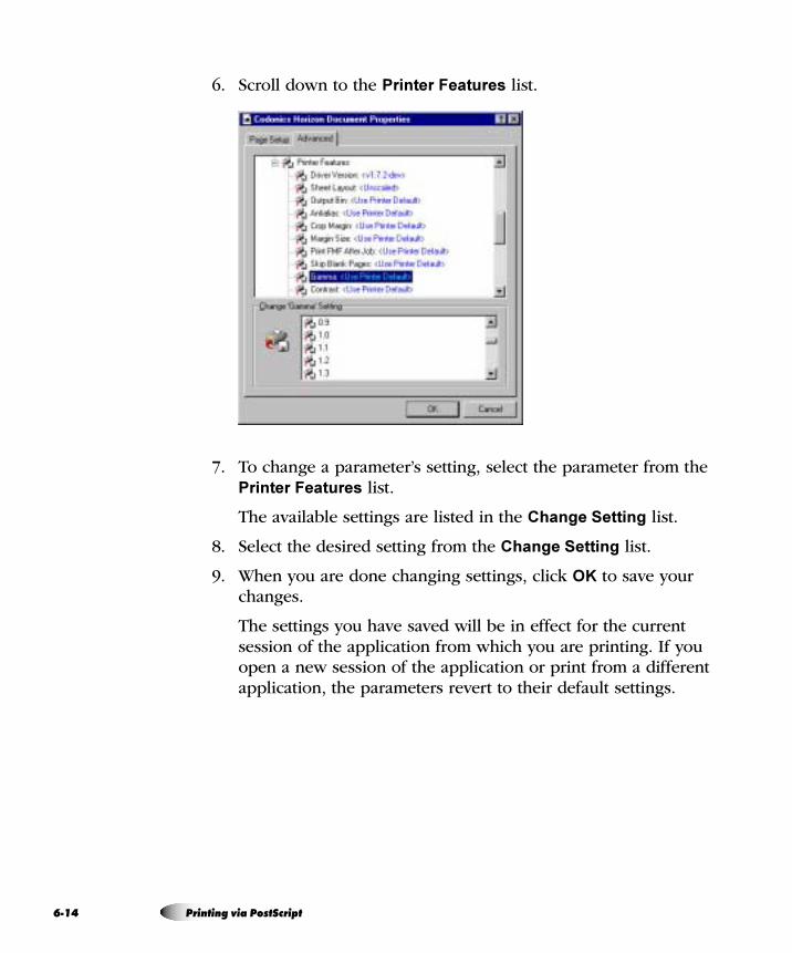
6-1
6. Scroll down to the Printer Features list.
7. To change a parameter’s setting, select the parameter from the Printer Features list.
The available settings are listed in the Change Setting list.
8. Select the desired setting from the Change Setting list.
9. When you are done changing settings, click OK to save your changes.
The settings you have saved will be in effect for the current session of the application from which you are printing. If you open a new session of the application or print from a different application, the parameters revert to their default settings.
4 Printing via PostScript
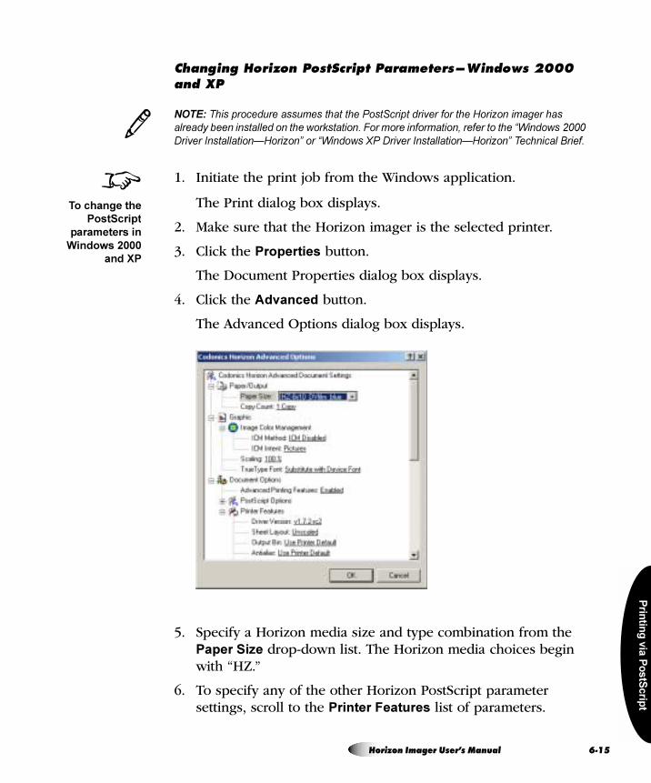
Prin
ting
via
Po
stS
crip
t
`Ü~åÖáåÖ=eçêáòçå=mçëípÅêáéí=m~ê~ãÉíÉêëÔtáåÇçïë OMMM=~åÇ=um
NOTE: This procedure assumes that the PostScript driver for the Horizon imager has
already been installed on the workstation. For more information, refer to the “Windows 2000
Driver Installation—Horizon” or “Windows XP Driver Installation—Horizon” Technical Brief.
1. Initiate the print job from the Windows application.
The Print dialog box displays.
2. Make sure that the Horizon imager is the selected printer.
3. Click the Properties button.
The Document Properties dialog box displays.
4. Click the Advanced button.
The Advanced Options dialog box displays.
5. Specify a Horizon media size and type combination from the Paper Size drop-down list. The Horizon media choices begin with “HZ.”
6. To specify any of the other Horizon PostScript parameter settings, scroll to the Printer Features list of parameters.
3
8To change the
PostScript
parameters in
Windows 2000
and XP
Horizon Imager User’s Manual 6-15
6-1
7. When you are done changing settings, click OK to save your changes.
The settings you have saved will be in effect for the current session of the application from which you are printing. If you open a new session of the application or print from a different application, the parameters revert to their default settings.
Once the Horizon imager is set up as a printer on your Macintosh (which is described in the two Macintosh Driver Installation—Horizon Technical Briefs, one for OS 8 and 9 and one for OS X), you can send images to it for printing from any Macintosh application.
To print to the Horizon imager, you first use the application’s Page Setup function to select the Horizon media size and type. Then, you use the standard Print dialog box to select the Horizon imager as the print destination and set the Horizon PostScript parameters.
péÉÅáÑóáåÖ=íÜÉ=eçêáòçå=jÉÇá~
Before sending a print job to the Horizon imager, you must select the Horizon media size and type using the application’s Page Setup function. The available choices are listed in Table 6-2 on page 6-21.
mêáåíáåÖ=Ñêçã=j~ÅáåíçëÜ=^ééäáÅ~íáçåë
6 Printing via PostScript
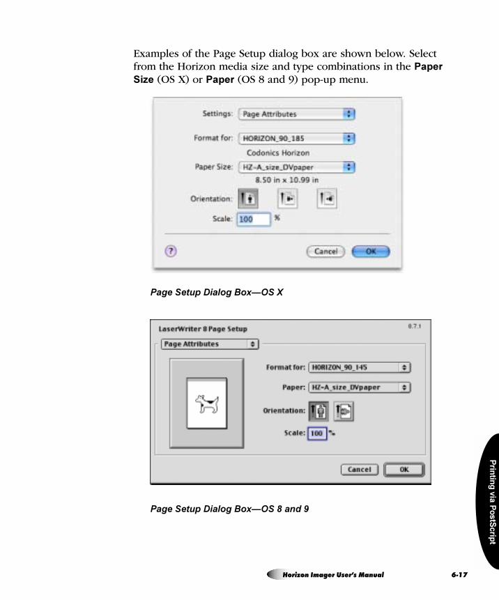
Prin
ting
via
Po
stS
crip
t
Examples of the Page Setup dialog box are shown below. Select from the Horizon media size and type combinations in the Paper
Size (OS X) or Paper (OS 8 and 9) pop-up menu.
Page Setup Dialog Box—OS X
Page Setup Dialog Box—OS 8 and 9
Horizon Imager User’s Manual 6-17
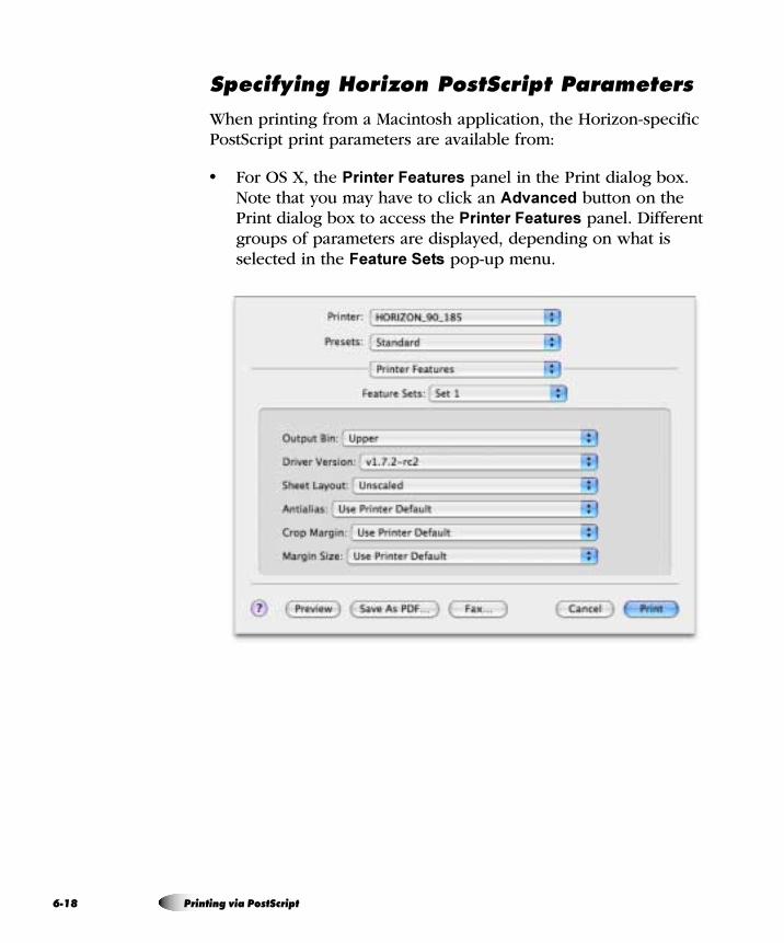
6-1
péÉÅáÑóáåÖ=eçêáòçå=mçëípÅêáéí=m~ê~ãÉíÉêë
When printing from a Macintosh application, the Horizon-specific PostScript print parameters are available from:
• For OS X, the Printer Features panel in the Print dialog box. Note that you may have to click an Advanced button on the Print dialog box to access the Printer Features panel. Different groups of parameters are displayed, depending on what is selected in the Feature Sets pop-up menu.
8 Printing via PostScript
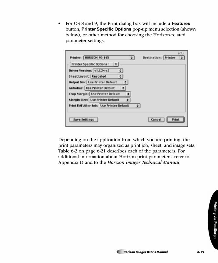
Prin
ting
via
Po
stS
crip
t
• For OS 8 and 9, the Print dialog box will include a Features button, Printer Specific Options pop-up menu selection (shown below), or other method for choosing the Horizon-related parameter settings.
Depending on the application from which you are printing, the print parameters may organized as print job, sheet, and image sets. Table 6-2 on page 6-21 describes each of the parameters. For additional information about Horizon print parameters, refer to Appendix D and to the Horizon Imager Technical Manual.
Horizon Imager User’s Manual 6-19
6-2
kçíÉë=^Äçìí=`Ü~åÖáåÖ=mçëípÅêáéí=m~ê~ãÉíÉêë
• There are other, non-Horizon-related parameters included in the set of available PostScript printer parameters. Because unpredictable results may occur, it is recommended that you change the defaults for only those Horizon imager parameters listed in Table 6-2 on page 6-21.
• Some of the “Selectable Values” shown in Table 6-2 may depend on available Horizon imager options and thus may not appear on some systems.
• Settings made at print time via the Print dialog boxes will take precedence over settings made at the imager. Note, however, that a “Use Printer Default” setting can be chosen for many of the parameters in the Print dialog box. Note that the exact wording of the “Use Printer Default” setting can vary depending on which Macintosh OS and application you are using.
0 Printing via PostScript
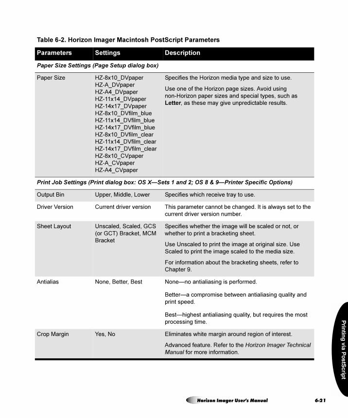
Prin
ting
via
Po
stS
crip
t
Table 6-2. Horizon Imager Macintosh PostScript Parameters
Parameters Settings Description
Paper Size Settings (Page Setup dialog box)
Paper Size HZ-8x10_DVpaper
HZ-A_DVpaper
HZ-A4_DVpaper
HZ-11x14_DVpaper
HZ-14x17_DVpaper
HZ-8x10_DVfilm_blue
HZ-11x14_DVfilm_blue
HZ-14x17_DVfilm_blue
HZ-8x10_DVfilm_clear
HZ-11x14_DVfilm_clear
HZ-14x17_DVfilm_clear
HZ-8x10_CVpaper
HZ-A_CVpaper
HZ-A4_CVpaper
Specifies the Horizon media type and size to use.
Use one of the Horizon page sizes. Avoid using
non-Horizon paper sizes and special types, such as
Letter, as these may give unpredictable results.
Print Job Settings (Print dialog box: OS X—Sets 1 and 2; OS 8 & 9—Printer Specific Options)
Output Bin Upper, Middle, Lower Specifies which receive tray to use.
Driver Version Current driver version This parameter cannot be changed. It is always set to the
current driver version number.
Sheet Layout Unscaled, Scaled, GCS
(or GCT) Bracket, MCM
Bracket
Specifies whether the image will be scaled or not, or
whether to print a bracketing sheet.
Use Unscaled to print the image at original size. Use
Scaled to print the image scaled to the media size.
For information about the bracketing sheets, refer to
Chapter 9.
Antialias None, Better, Best None—no antialiasing is performed.
Better—a compromise between antialiasing quality and
print speed.
Best—highest antialiasing quality, but requires the most
processing time.
Crop Margin Yes, No Eliminates white margin around region of interest.
Advanced feature. Refer to the Horizon Imager Technical Manual for more information.
Horizon Imager User’s Manual 6-21
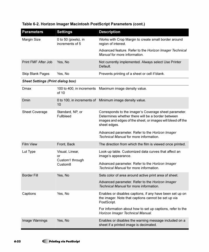
6-2
Margin Size 0 to 50 (pixels), in
increments of 5
Works with Crop Margin to create small border around
region of interest.
Advanced feature. Refer to the Horizon Imager Technical Manual for more information.
Print FMF After Job Yes, No Not currently implemented. Always select Use Printer
Default.
Skip Blank Pages Yes, No Prevents printing of a sheet or cell if blank.
Sheet Settings (Print dialog box)
Dmax 100 to 400, in increments
of 10
Maximum image density value.
Dmin 0 to 100, in increments of
10
Minimum image density value.
Sheet Coverage Standard, NP, or
Fullbleed
Corresponds to the imager’s Coverage sheet parameter.
Determines whether there will be a border between
images and edges of the sheet, or images will bleed off the
sheet edges.
Advanced parameter. Refer to the Horizon Imager Technical Manual for more information.
Film View Front, Back The direction from which the film is viewed once printed.
Lut Type Visual, Linear,
or
Custom1 through
Custom8
Look-up table. Customized data curves that affect an
image’s appearance.
Advanced parameter. Refer to the Horizon Imager Technical Manual for more information.
Border Fill Yes, No Sets color of area around active print area of sheet.
Advanced parameter. Refer to the Horizon Imager Technical Manual for more information.
Captions Yes, No Enables or disables captions, if any have been set up on
the imager. Note that captions cannot be set up via
PostScript.
For information about how to set up captions, refer to the
Horizon Imager Technical Manual.
Image Warnings Yes, No Enables or disables the warning message included on a
sheet if a printed image is decimated.
Table 6-2. Horizon Imager Macintosh PostScript Parameters (cont.)
Parameters Settings Description
2 Printing via PostScript
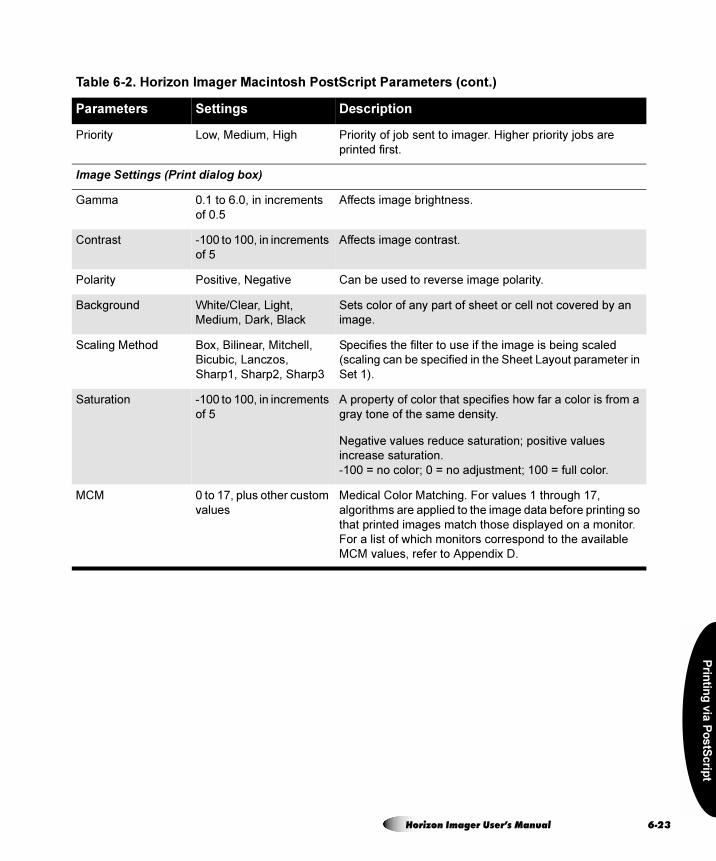
Prin
ting
via
Po
stS
crip
t
Priority Low, Medium, High Priority of job sent to imager. Higher priority jobs are
printed first.
Image Settings (Print dialog box)
Gamma 0.1 to 6.0, in increments
of 0.5
Affects image brightness.
Contrast -100 to 100, in increments
of 5
Affects image contrast.
Polarity Positive, Negative Can be used to reverse image polarity.
Background White/Clear, Light,
Medium, Dark, Black
Sets color of any part of sheet or cell not covered by an
image.
Scaling Method Box, Bilinear, Mitchell,
Bicubic, Lanczos,
Sharp1, Sharp2, Sharp3
Specifies the filter to use if the image is being scaled
(scaling can be specified in the Sheet Layout parameter in
Set 1).
Saturation -100 to 100, in increments
of 5
A property of color that specifies how far a color is from a
gray tone of the same density.
Negative values reduce saturation; positive values
increase saturation.
-100 = no color; 0 = no adjustment; 100 = full color.
MCM 0 to 17, plus other custom
values
Medical Color Matching. For values 1 through 17,
algorithms are applied to the image data before printing so
that printed images match those displayed on a monitor.
For a list of which monitors correspond to the available
MCM values, refer to Appendix D.
Table 6-2. Horizon Imager Macintosh PostScript Parameters (cont.)
Parameters Settings Description
Horizon Imager User’s Manual 6-23
6-2
p~îáåÖ=eçêáòçå=mêáåí=pÉííáåÖë=~ë=mêÉëÉíë=áå=lp u
A standard OS X Print feature is the ability to save the current parameter settings in the Print dialog box as a preset. This allows you to choose from a list of presets to automatically select common combinations of print parameter settings. The presets are accessible from any OS X application.
So, for example, you can use the Preset function to save a preset for each combination of Horizon PostScript print settings that you commonly use.
To save the current settings as a preset, select Save As from the Presets pop-up menu, and name the preset.
The next time you want to use that combination of settings, you can simply choose its preset from the Presets pop-up menu. You can also then change any of that preset’s default settings, as necessary for that particular print job.
p~îáåÖ=eçêáòçå=mêáåí=pÉííáåÖë=áå lp U ~åÇ V
A standard OS 8 and 9 Print feature is the ability to save the current parameter settings in the Print dialog box.
The exact method used differs from application to application. With some applications, the most recently used print parameter settings are saved automatically with the file when the file is saved. With other applications, a Save Settings button may be included on the Print Dialog box to allow you to save the current settings as the defaults for any file opened in the application. Refer to your application’s documentation for further details.
4 Printing via PostScript
Prin
ting
via
FT
P a
nd
LP
R
= TmêáåíáåÖ=îá~=cqm=~åÇ=imo
Support for receiving print jobs via FTP and LPR comes standard with the imager. FTP and LPR are advanced methods for sending print jobs, typically used by system integrators. This chapter provides basic instructions for sending print jobs via FTP and LPR. However, for a complete explanation about how to use these methods, refer to the Horizon Imager Technical Manual.
FTP (File Transfer Protocol) is a protocol that enables you to login to the Horizon imager from your workstation and send image files to be printed. You can also send text files containing custom commands and parameters used to set up your sheets and process the images.
FTP uses the TCP/IP networking protocol and is available for most computer platforms, including UNIX, Linux, MS-DOS/Windows, and Macintosh.
The procedure that follows explains how to FTP image files from a command window on your workstation. If you are using a GUI-based FTP application, you will likely click buttons and drag files from one window to another instead of entering commands.
mêáåíáåÖ=îá~=cqm
Horizon Imager User’s Manual 7-1
7-2
While the user interface may vary between implementations of FTP, the information required to connect to the imager and send files is the same.
To print a sheet, you simply start an FTP session with the imager, login to the FTP session using a logical device as the password to indicate what format to use, then send one or more images to be printed on the sheet.
1. From your workstation, open a command window.
2. To start the FTP session, at the command prompt enter the following command:
ftp x.x.x.x
where x.x.x.x is the IP address of the Horizon imager to which you want to send the print job.
NOTE: If you have configured a host alias for the Horizon imager on your workstation or you
are using Domain Name Service (DNS), you can enter the imager’s host name instead of
the IP address.
FTP connects with the imager and you are prompted to log in.
3. Enter a name to identify yourself to the Horizon imager.
NOTE: The Horizon imager does not maintain FTP user accounts, so you can really enter
any name you want. However, the imager does track print jobs by the source user login/host.
Therefore, it is recommended that you use a name that is unique among other users of the
imager. This will also allow you to identify your jobs in the imager’s log information.
You are prompted for a password.
4. At the password prompt, you need to enter the Horizon logical device number that represents the sheet format you want to use:
• To print a single image, enter 1 (unscaled) or 2 (scaled).
8To print a sheet
using FTP
3
3
Printing via FTP and LPR
Prin
ting
via
FT
P a
nd
LP
R
• To print multiple images on a sheet using Fixed Multiformatting™ (FMF™), enter the number from 11 to 99 that corresponds to the sheet format you want to use. The first digit in the logical device specifies the number of columns in the image cell matrix, and the second digit specifies the number of rows.
For example, logical device 12 corresponds to a 1 x 2-image sheet (one image stacked on another); logical device 23 corresponds to a 2 x 3-image sheet (6-up format—2 columns by 3 rows). For more information about FMF, refer to the Horizon Imager Technical Manual.
• To specify a Job Settings file, append a period (.) and the Job Settings file name after the logical device number. For example:
23.MYSETTINGS1
After entering the logical device number at the password prompt, you are logged in to an FTP session on the imager.
5. Specify that you want to transfer files in binary mode by entering the following command (on some systems, binary mode is called image mode):
ftp> bin
You can now begin transferring image files to the imager.
6. Use the put command to send one or more images to the imager; for example:
ftp> put image1.tif
ftp> put image2.tif
7. You can also specify multiple files in one mput command. Before entering the mput command, you can turn off its confirmation prompting prior to sending each file by first entering the prompt command:
ftp> prompt
ftp> mput image1.tif image2.tif
Horizon Imager User’s Manual 7-3
7-4
Multiple files are placed sequentially in the cells on the sheet, moving from left to right, top to bottom. When you send enough images to fill the selected sheet format, the sheet is automatically printed. (To toggle file confirmation back on, simply enter the prompt command again.)
NOTE: To force a sheet that is not full of images to print, create an ASCII text file whose
content is simply the word print. (It does not matter what you call the file, or whether
print is in upper or lower case letters.) Then use the put command to send the text file to
the imager.
8. To send another print job using the same sheet format, use the put command to send the image(s) to the imager.
9. When you are finished sending images to be printed and want to close the FTP session, enter quit.
There are some other common operations that you may want to perform during an FTP session. For complete information about how to send print jobs using FTP, refer to the Horizon Imager Technical Manual.
péÉÅáÑóáåÖ=íÜÉ=jÉÇá~=qóéÉ=~åÇ=páòÉ=rëáåÖ=cqm
To set the media type and size to use for a given print job using FTP, you have two options:
• Simply send the print job. The Horizon imager can determine whether the image is grayscale or color. The imager will then use the default media type/size defined for that image type. For more information about how to define the default media type/size to use for grayscale and color images, refer to “Changing the Default Media Type and Size” on page 8-3.
• Use a Job Settings file that specifies the media type/size that you want to print to. For more information on Job Settings files, refer to the Horizon Imager Technical Manual.
3
Printing via FTP and LPR
Prin
ting
via
FT
P a
nd
LP
R
LPR (originally named for line printer) is a printing tool that enables you to send files to the Horizon imager.
LPR uses the TCP/IP networking protocol and is most commonly used in UNIX and Linux, and to a lesser extent in Windows and other operating systems. Most LPR implementations have easy-to-use commands for sending files to the imager. However, they do require setup by a system administrator for correct operation. Instructions for setting up LPR to work with the Horizon imager are provided in the Horizon Imager Technical Manual.
To print jobs to the Horizon imager using LPR, use the lpr command as follows:
lpr -Pname [-#c] [-s] imagefile1 [imagefile2] ...
where:
mêáåíáåÖ=îá~=imo
-Pname is the name for the Horizon imager logical device/Job
Settings file combination that you want to use.
The names for the available combinations are typically
defined by a system administrator during LPR setup.
-#c is a command option that allows you to specify the number of
copies, c, to print. If not defined, one sheet will be printed.
-s is a command option that causes LPR to send the images
directly to the Horizon imager, and not store them temporarily
in the spool directory. This option can save printing time. If
used, you cannot delete the image file being sent until it is
finished printing.
imagefiles are the image files to be printed on the sheet. Image cells are
filled left to right, top to bottom.
Horizon Imager User’s Manual 7-5
7-6
bñ~ãéäÉë=çÑ=mêáåíáåÖ=rëáåÖ=imo
For the first example, assume that the LPR printer horizon2 has been configured to print 1-up scaled image sheets using the imager’s Default User Settings (that is, no Job Settings file has been specified in the printer’s configuration). To print 3 copies of a single scaled image called image.tif, you would enter:
lpr -Phorizon2 -#3 image.tif
For the second example, assume that the LPR printer horizon23MJS4 has been configured to print 6-up FMF sheets using the Job Settings file MYSETTINGS4. To print 1 copy of 6 JPEG image files without spooling the image files, you would enter:
lpr -Phorizon23MJS4 -s image1.jpg image2.jpg ... image6.jpg
There are some other common operations that you may want to perform using the LPR. For complete information about how to send print jobs using LPR, refer to the Horizon Imager Technical Manual.
péÉÅáÑóáåÖ=íÜÉ=jÉÇá~=qóéÉ=~åÇ=páòÉ=rëáåÖ=imo
To set the media type and size to use for a given print job using LPR, you have two options:
• Simply send the print job. The Horizon imager will determine whether the image is grayscale or color. The imager will then use the default media type/size defined for that image type. For more information about how to define the default media type/size to use for grayscale and color images, refer to “Changing the Default Media Type and Size” on page 8-3.
• Use a Job Settings file that specifies the media type/size on which you want to print. For more information on Job Settings files, refer to the Horizon Imager Technical Manual.
Printing via FTP and LPR
Defa
ult P
rint J
ob
Se
tting
s
= UaÉÑ~ìäí=mêáåí=gçÄ=pÉííáåÖë
Every print job has parameters associated with it that control how the job is to be processed (for example, media size and type, scaling, gamma, contrast, and so on).
The Horizon imager has a complete set of default settings that contain values for every media type/size, sheet, and image parameter of a print job. The default settings are stored in the imager and can be viewed and changed through the control panel. Once changed, you can also change back to the original factory-default settings at any time.
If a print job parameter has not been defined from within the sending user application, in a selected Job Settings file, or in a Zip disk settings.txt file, the imager’s Default Media and Default User Settings are used.
Refer to Appendix D for a summary of the print job parameters that can be changed at the control panel. Note that many of these parameters require a good understanding of what effect changing the parameter’s setting will have on printed images and sheets. For a full discussion of each parameter, refer to the Horizon Imager Technical Manual. You can also refer to the Technical Manual for information about using Job Settings files and printing files automatically from a Zip disk.
CAUTION Use caution when changing the imager default settings. Changes could
affect prints made by other users.
Horizon Imager User’s Manual 8-1
8-2
If the factory-default settings do not meet your printing requirements, you can change parameter settings at the control panel. You can change the:
• Default media to use for grayscale or color images
• Default sheet and image parameter settings (referred to in the administrative Main Menu as the “Default User Settings”) for each media type
Changing the default settings overrides the factory defaults, but does not delete them. You can easily reset the factory defaults at any time. For more information, refer to “Resetting to Factory-Default Settings” on page 8-7.
NOTE: Changes to the default settings apply only to new incoming print jobs. Jobs already
queued for printing are printed using the default settings that were in effect when the print
job was received.
`Ü~åÖáåÖ=aÉÑ~ìäí=pÉííáåÖë
CAUTION Changing the default settings will affect prints made by other users. Use
caution when changing default settings. Typically, it is better to specify sheet and
image parameter settings from the DICOM application or a PostScript printer’s
settings, or use a Job Settings file that contains the values you need. For information
about Job Settings files, refer to the Horizon Imager Technical Manual.
3
Default Print Job Settings
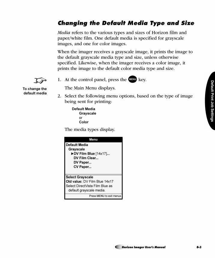
Defa
ult P
rint J
ob
Se
tting
s
`Ü~åÖáåÖ=íÜÉ=aÉÑ~ìäí=jÉÇá~=qóéÉ=~åÇ=páòÉ
Media refers to the various types and sizes of Horizon film and paper/white film. One default media is specified for grayscale images, and one for color images.
When the imager receives a grayscale image, it prints the image to the default grayscale media type and size, unless otherwise specified. Likewise, when the imager receives a color image, it prints the image to the default color media type and size.
1. At the control panel, press the key.
The Main Menu displays.
2. Select the following menu options, based on the type of image being sent for printing:
Default Media
Grayscale
or
Color
The media types display.
Menu
Default Media
Grayscale
�DV Film Blue [14x17]...
DV Film Clear...
DV Paper...
CV Paper...
Select Grayscale
Old value: DV Film Blue 14x17
Select DirectVista Film Blue as
default grayscale media.
Press MENU to exit menus
8To change the
default media
MENU
Horizon Imager User’s Manual 8-3
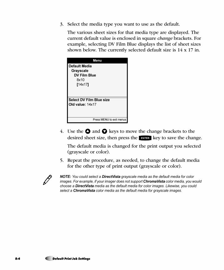
8-4
3. Select the media type you want to use as the default.
The various sheet sizes for that media type are displayed. The current default value is enclosed in square change brackets. For example, selecting DV Film Blue displays the list of sheet sizes shown below. The currently selected default size is 14 x 17 in.
4. Use the and keys to move the change brackets to the desired sheet size, then press the key to save the change.
The default media is changed for the print output you selected (grayscale or color).
5. Repeat the procedure, as needed, to change the default media for the other type of print output (grayscale or color).
NOTE: You could select a DirectVista grayscale media as the default media for color
images. For example, if your imager does not support ChromaVista color media, you would
choose a DirectVista media as the default media for color images. Likewise, you could
select a ChromaVista color media as the default media for grayscale images.
Menu
Default Media
Grayscale
DV Film Blue
8x10
[14x17]
Select DV Film Blue size
Old value: 14x17
Press MENU to exit menus
� �
ENTER
3
Default Print Job Settings
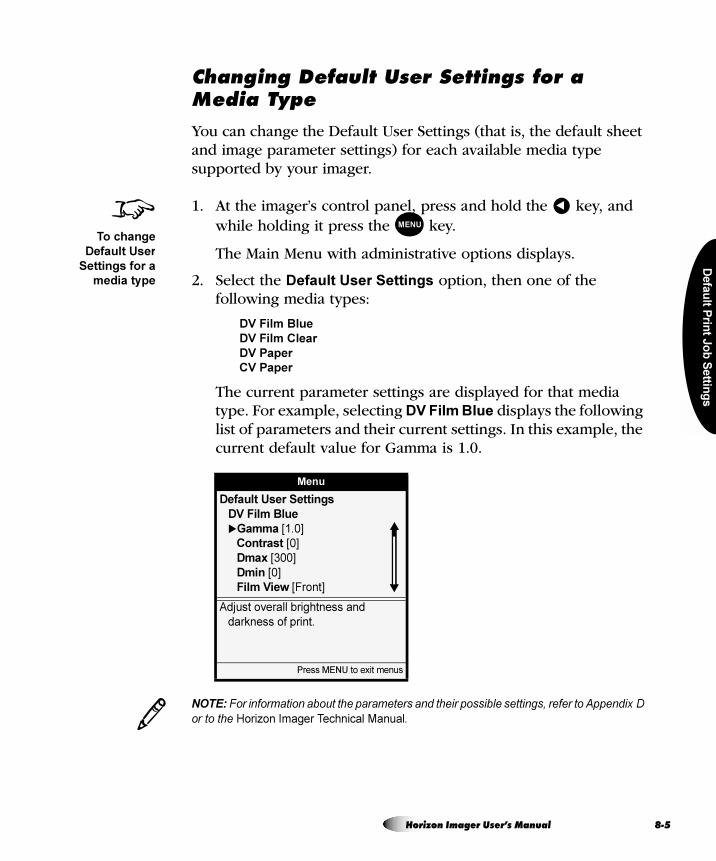
Defa
ult P
rint J
ob
Se
tting
s
`Ü~åÖáåÖ=aÉÑ~ìäí=rëÉê=pÉííáåÖë=Ñçê=~=jÉÇá~=qóéÉ
You can change the Default User Settings (that is, the default sheet and image parameter settings) for each available media type supported by your imager.
1. At the imager’s control panel, press and hold the key, and while holding it press the key.
The Main Menu with administrative options displays.
2. Select the Default User Settings option, then one of the following media types:
DV Film Blue
DV Film Clear
DV Paper
CV Paper
The current parameter settings are displayed for that media type. For example, selecting DV Film Blue displays the following list of parameters and their current settings. In this example, the current default value for Gamma is 1.0.
NOTE: For information about the parameters and their possible settings, refer to Appendix D
or to the Horizon Imager Technical Manual.
Menu
Default User Settings
DV Film Blue
�Gamma [1.0]
Contrast [0]
Dmax [300]
Dmin [0]
Film View [Front]
Adjust overall brightness and
darkness of print.
Press MENU to exit menus
8To change
Default User
Settings for a
media type
�
MENU
3
Horizon Imager User’s Manual 8-5
8-6
3. Scroll through the parameters for this media type, and change the default settings, as needed.
For example, to change the Gamma default setting, select the Gamma menu entry and then, in the Gamma setting menu, use the and keys to enter a new value inside the change brackets.
4. Repeat the procedure, as needed, to change the default settings for other media types supported by your imager.
� �
Default Print Job Settings
Defa
ult P
rint J
ob
Se
tting
s
If you configured your own default settings, you can reset them to the factory defaults at any time.
Resetting to the factory default settings applies only to new incoming print jobs. Jobs already queued for printing are printed using the default settings that were in effect when the print job was received.
oÉëÉííáåÖ=íÜÉ=aÉÑ~ìäí=jÉÇá~=pÉäÉÅíáçåë
You can reset the Default Media selections for grayscale or color images back to the factory-default selections.
1. At the imager’s control panel, press the key.
The Main Menu displays.
2. Select the following menu options:
Default Media
Reset Default Media
You are prompted to confirm the reset.
3. Respond to the confirmation prompt.
The factory-default selections are restored.
oÉëÉííáåÖ=íç=c~ÅíçêóJaÉÑ~ìäí=pÉííáåÖë
CAUTION If the imager’s settings were changed from the factory defaults prior to
being shipped (for example, to accommodate a special OEM configuration), resetting
to the factory defaults will not restore the “as shipped” settings. Instead, they will be
reset to the standard factory default values.
CAUTION Resetting to the factory defaults will affect prints made by other users. Use
caution when changing default settings. Typically, it is better to specify sheet and
image parameter settings from the DICOM application or a PostScript printer’s
settings, or use a Job Settings file that contains the values you need. For information
about Job Settings files, refer to the Horizon Imager Technical Manual.
8To reset the
Default Media
selections to
their factory
defaults
MENU
Horizon Imager User’s Manual 8-7
8-8
oÉëÉííáåÖ=íÜÉ=aÉÑ~ìäí=rëÉê=pÉííáåÖë
You can reset the Default User Settings for all media types back to the factory-default settings.
1. At the imager’s control panel, press and hold the key, and
while holding it press the key.
The Main Menu with administrative options displays.
2. Select the following menu options:
Default User Settings
Reset User Settings
You are prompted to confirm the reset.
3. Respond to the confirmation prompt.
The factory-default settings are restored.
8To reset the
Default User
Settings for all
media types
and sizes to
their factory
defaults
�
MENU
Default Print Job Settings
Ad
jus
ting
Ima
ge
Ap
pea
ran
ce
= V^ÇàìëíáåÖ=fã~ÖÉ=^ééÉ~ê~åÅÉ
You can use the Horizon Bracketing™ function to assist you in determining the gamma, contrast, saturation, and MCM (Medical Color Matching) settings that will result in the desired appearance for printed images.
This chapter explains how to print gamma/contrast/saturation (GCS; for PostScript, referred to as “GCT”) or MCM bracketing sheets via DICOM or PostScript, then how to use the print to select the desired settings. For information about how to print bracketing sheets using FTP or LPR, refer to the Horizon Imager Technical Manual.
NOTE: Image parameters—including Dmax, gamma, contrast, saturation, and MCM—are
intended to compensate for differences that may occur between image acquisition and
image printing. These parameters allow you to adjust the appearance of a printed image so
that it is satisfactory for your application. Care should be used when setting these
parameters to avoid overcompensation. Refer to Appendix D for typical setting ranges.
DirectVista is optimized for grayscale prints, while ChromaVista is optimized for color prints. If ChromaVista is not giving you satisfactory results with grayscale images, you may want to consider using DirectVista media for those applications.
3
`Üêçã~sáëí~=~åÇ=dê~óëÅ~äÉ=fã~ÖÉë
Horizon Imager User’s Manual 9-1
9-2
For best results when viewing printed images, follow these guidelines:
• Codonics film media is designed to be viewed using a light box suitable for viewing medical diagnostic images.
• Codonics paper/white film media is designed to be viewed under cool-white, fluorescent light. Spectral differences and intensity variations in the viewing light sources can change the apparent color of images printed on paper/white film.
If you plan to use MCM settings, then you should use both GCS and MCM bracketing sheets to determine the combination of settings that result in the desired image appearance.
A general strategy for using both the GCS and MCM bracketing sheets is:
1. If an MCM setting has not been recommended, print an MCM bracketing sheet, using a representative image, and select the MCM setting that provides the best color match to your monitor.
2. After determining the MCM setting, print a gamma/contrast bracketing sheet to fine-tune the overall brightness and contrast of the image. For most applications, the gamma setting will be from 0.90 to 1.25, and the contrast setting will be from 0 to 20.
dìáÇÉäáåÉë=Ñçê=sáÉïáåÖ=mêáåíÉÇ=fã~ÖÉë
dÉåÉê~ä=_ê~ÅâÉíáåÖ=dìáÇÉäáåÉë
Adjusting Image Appearance
Ad
jus
ting
Ima
ge
Ap
pea
ran
ce
3. If using ChromaVista media, print a gamma/saturation bracketing sheet to determine the saturation setting that provides the best color intensity. For most applications, the saturation setting will be from 0 to 20.
4. Repeat the process to fine-tune the settings.
A gamma/contrast bracketing sheet includes 20 copies of the same image, with each copy having different gamma and contrast settings. When printing to ChromaVista media, a second gamma/saturation bracketing sheet that varies gamma and saturation settings for each image is also printed.
You create a gamma/contrast bracketing sheet by printing a representative image using nominal gamma and contrast settings (for example, the factory defaults). In the printed sheet, the image with the nominal settings is indicated by a gray background. The other versions of the image are created by varying gamma and/or contrast from the nominal settings. The gamma and contrast settings used are overprinted at the top left corner of each image.
Using this print, you can select the image with the best appearance for your application, which in turn indicates the gamma and contrast settings to use to achieve that appearance.
For ChromaVista color prints, you can then use the gamma/saturation bracketing sheet to determine the gamma and saturation settings that result in the best color appearance for your application.
NOTE: For optimal image quality, use the typical range of settings described in Appendix D.
d`p=_ê~ÅâÉíáåÖ=pÜÉÉíë
3
Horizon Imager User’s Manual 9-3
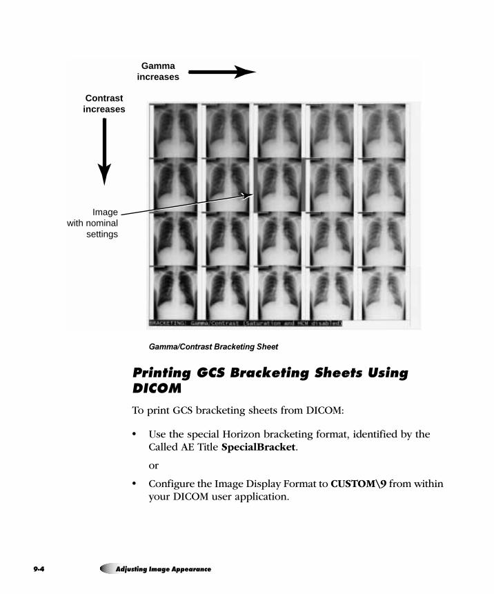
9-4
Gamma/Contrast Bracketing Sheet
mêáåíáåÖ=d`p=_ê~ÅâÉíáåÖ=pÜÉÉíë=rëáåÖ=af`lj
To print GCS bracketing sheets from DICOM:
• Use the special Horizon bracketing format, identified by the Called AE Title SpecialBracket.
or
• Configure the Image Display Format to CUSTOM\9 from within your DICOM user application.
Contrast increases
Gamma increases
Image with nominal
settings
Adjusting Image Appearance
Ad
jus
ting
Ima
ge
Ap
pea
ran
ce
If you do not specify the media type and size for the bracketing sheet from within the DICOM user application, then the Horizon imager determines whether the image is grayscale or color. The imager then uses the Default Media defined for that type of image, and the Default User Settings defined for that media type and size. For more information about how to define the Default Media selection and Default User Settings, refer to “Changing the Default Media Type and Size” on page 8-3 and “Changing Default User Settings for a Media Type” on page 8-5.
Once a bracketing sheet is printed, you can use it to make the proper image parameter adjustments, which is described in “DirectVista Adjustments” on page 9-5 and “ChromaVista Adjustments” on page 9-7.
mêáåíáåÖ=d`p=_ê~ÅâÉíáåÖ=pÜÉÉíë=rëáåÖ=mçëípÅêáéí
To print GCS bracketing sheets via PostScript, set the Sheet Layout parameter to GCS (or GCT) Bracket, and specify the media type/size using the Media Type and Media Size settings. For more information about changing parameter settings when printing via PostScript, refer to Chapter 6.
Once a bracketing sheet is printed, you can use it to make the proper image setting adjustments, which is described in the next topic, “DirectVista Adjustments”, and in “ChromaVista Adjustments” on page 9-7.
aáêÉÅísáëí~=^ÇàìëíãÉåíë
To find the best gamma and contrast settings for images printed on DirectVista media:
1. If printing to film, select the Dmax value that is consistent with your application.
If printing to paper/white film, go to step 3.
Horizon Imager User’s Manual 9-5
9-6
NOTE: Depending on the application, you can change Dmax, gamma, or contrast in the
following ways: (1) from the DICOM user application or PostScript printer settings;
(2) changing the Default Media and Default User Settings as the imager control panel (refer
to Chapter 8); (3) using Job Settings files (refer to the Horizon Imager Technical Manual).
Making these changes does not affect jobs already in the print queue.
2. Make several test prints using an image that is typical for your application, varying Dmax for each print.
When the blackest part of the image is black enough, stop and go to the next step. Otherwise, adjust Dmax and make another print.
3. Print the image as a gamma/contrast bracketing sheet job for gamma and contrast.
It is recommended that you use the factory defaults for gamma and contrast when making bracketing sheets. However, you can leave them as is if you have already changed the default settings to preferred values.
4. Examine the bracketing sheet and select the copy with the best appearance.
If none of the copies are satisfactory, reprint the bracketing sheet using the settings of the best copy. Repeat this until one of the image copies is acceptable.
5. Set gamma and contrast to the settings used to create the acceptable image.
6. Send a print job that includes various images that are typical for your application.
Check the appearance of these images and make any necessary fine adjustments to gamma and contrast until the images are acceptable.
CAUTION Changing the imager’s Default Media and Default User Settings could
affect subsequent prints made by other users. Use caution when changing default
settings.
3
Adjusting Image Appearance
Ad
jus
ting
Ima
ge
Ap
pea
ran
ce
7. Once you find the most suitable gamma and contrast settings, you should use them for future print jobs. For example, you should update the imager’s Default User Settings and any Job Settings files that you use.
8. Once you have the imager configured as you want it using this procedure, you should save the configuration settings to backup media. For more information about how to save configuration settings, refer to “Saving the Configuration Settings” on page 2-20.
`Üêçã~sáëí~=^ÇàìëíãÉåíë
To find the best gamma, contrast, and saturation settings for color images printed on ChromaVista media, you:
1. Determine the best gamma and contrast settings, as described in “DirectVista Adjustments” on page 9-5. The only exception is that you can ignore the instructions about finding the setting for Dmax. The Dmax parameter does not apply to color media.
2. Using an image that is typical for your application, print a color image bracketing sheet, using the gamma and contrast settings determined in step 1.
3. Examine the gamma/saturation bracketing sheet and select the copy with the best appearance.
If none of the copies are satisfactory, reprint the bracketing sheet using the settings of the best copy. Repeat this until one of the image copies is acceptable.
NOTE: Depending on the application, you can change gamma or saturation in the following
ways: (1) from the DICOM user application or PostScript printer settings; (2) changing the
Default Media and Default User Settings as the imager control panel (refer to Chapter 8);
(3) using Job Settings files (refer to the Horizon Imager Technical Manual). Making these
changes does not affect jobs already in the print queue.
CAUTION Changing the imager’s Default Media and Default User Settings could
affect subsequent prints made by other users. Use caution when changing default
settings.
3
Horizon Imager User’s Manual 9-7
9-8
4. Set gamma and saturation to the settings used to create the acceptable image.
5. Send a print job that includes various images that are typical for your application.
Check the appearance of these images and make any necessary fine adjustments to gamma and saturation until the images are acceptable.
6. Once you find the most suitable gamma and saturation settings, you should use them for future print jobs. For example, you should update the imager’s Default User Settings and any Job Settings files that you use.
7. Once you have the imager configured as you want it using this procedure, you should save the configuration settings to backup media. For more information about how to save configuration settings, refer to “Saving the Configuration Settings” on page 2-20.
dìáÇÉäáåÉë=Ñçê=pÉäÉÅíáåÖ=p~íìê~íáçå=pÉííáåÖ
The default setting 0 is optimized for the smoothest blending of color mapping and grayscale, the maximum number of colors, and accurate sensitometry, but not necessarily for the most vibrant color appearance.
Extra saturation can work well with photographs, as it can make colors look more vibrant. However, be aware that if the saturation setting is too high, the printed image can include artifacts (due to discontinuities in the color mapping).
Adjusting Image Appearance
Ad
jus
ting
Ima
ge
Ap
pea
ran
ce
Codonics MCM is an advanced image processing feature that adjusts printed output colors to more accurately match monitors. This process corrects differences in hue, saturation, and intensity between the imager and a computer monitor. The MCM parameter determines for which monitor type MCM should be optimized.
An MCM bracketing sheet includes 11 copies of the same image, with each copy using one of the standard MCM settings, 0 through 10. The MCM settings used are overprinted at the top left corner of each image. For a list of the MCM settings and to which monitors they correspond, refer to Appendix D.
Using this print, you can determine the image that best matches the image as viewed at a diagnostic monitor, and use the corresponding MCM setting for print jobs.
j`j=_ê~ÅâÉíáåÖ=pÜÉÉíë
Horizon Imager User’s Manual 9-9
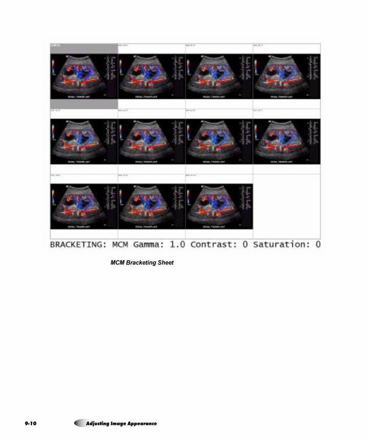
9-1
MCM Bracketing Sheet
0 Adjusting Image Appearance
Ad
jus
ting
Ima
ge
Ap
pea
ran
ce
mêáåíáåÖ=j`j=_ê~ÅâÉíáåÖ=pÜÉÉíë=rëáåÖ=af`lj
To print MCM bracketing sheets from DICOM, configure the Image Display Format to CUSTOM\8 from within your DICOM user application.
If you do not specify the media type and size for the bracketing sheet from within the DICOM user application, then the Horizon imager determines whether the image is grayscale or color. The imager then uses the Default Media defined for that type of image, and the Default User Settings defined for that media type and size. For more information about how to define the Default Media selection and Default User Settings, refer to “Changing the Default Media Type and Size” on page 8-3 and “Changing Default User Settings for a Media Type” on page 8-5.
Once a bracketing sheet is printed, you can use it to determine which MCM setting you want to use.
mêáåíáåÖ=j`j=_ê~ÅâÉíáåÖ=pÜÉÉíë=rëáåÖ=mçëípÅêáéí
To print MCM bracketing sheets via PostScript, set the Sheet Layout parameter to MCM Bracket, and specify the media type/size using the Media Type and Media Size settings. For more information about changing parameter settings when printing via PostScript, refer to Chapter 6.
Once a bracketing sheet is printed, you can use it to determine which MCM setting you want to use.
Horizon Imager User’s Manual 9-11

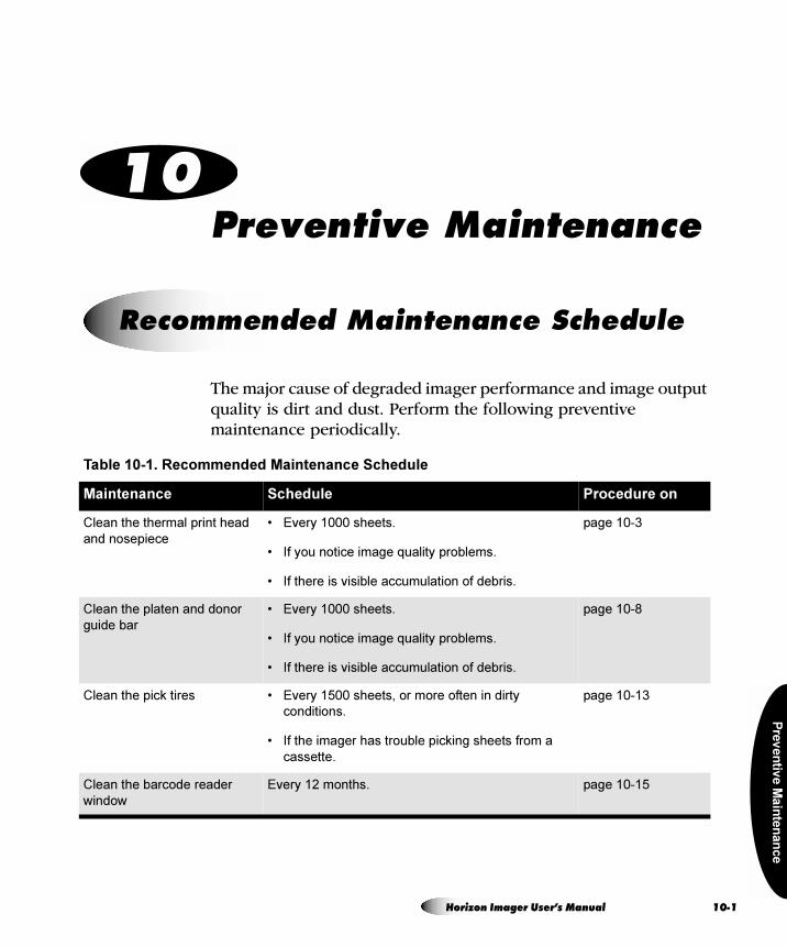
Pre
ve
ntiv
e M
ain
ten
an
ce
= NMmêÉîÉåíáîÉ=j~áåíÉå~åÅÉ
The major cause of degraded imager performance and image output quality is dirt and dust. Perform the following preventive maintenance periodically.
oÉÅçããÉåÇÉÇ=j~áåíÉå~åÅÉ=pÅÜÉÇìäÉ
Table 10-1. Recommended Maintenance Schedule
Maintenance Schedule Procedure on
Clean the thermal print head
and nosepiece
• Every 1000 sheets.
• If you notice image quality problems.
• If there is visible accumulation of debris.
page 10-3
Clean the platen and donor
guide bar
• Every 1000 sheets.
• If you notice image quality problems.
• If there is visible accumulation of debris.
page 10-8
Clean the pick tires • Every 1500 sheets, or more often in dirty
conditions.
• If the imager has trouble picking sheets from a
cassette.
page 10-13
Clean the barcode reader
window
Every 12 months. page 10-15
Horizon Imager User’s Manual 10-1

10
eçêáòçå=`äÉ~åáåÖ=háíë
The following cleaning kits are available to help you properly maintain the Horizon imager:
• The Horizon Platen and Print Head Cleaning Kit (catalog no. SP-00118) includes the special thermal print head and platen roller wipes that you will need to clean the thermal print head, platen, donor guide, and pick tires.
• The Horizon Barcode Reader Cleaning Kit (catalog no. SP-00130) includes the cotton swabs that you will need to clean the barcode reader window.
To order additional cleaning kits, contact Codonics at:
Phone: +1.440.243.1198
Toll Free: 800.444.1198 (USA only)
Fax: +1.440.243.1334
Web Site: www.codonics.com
Clean the cassette area, sheet
exit area, receive trays,
basement, and imager cabinet
with a platen roller wipe (refer
to “Horizon Cleaning Kits”
below)
Every 2000 sheets to eliminate dust buildup and
prevent dirt from getting inside the imager.
page 10-18
Thermal print head calibration Every 5000 sheets or 12 months, whichever comes
first.
Horizon Imager Technical Manual
Film calibration This calibration is done automatically whenever a
new cassette is inserted for the first time. You can
also run this calibration manually at any time (for
example, if it has been more than three months since
the cassette was calibrated).
page 11-2
Internal densitometer
calibration
As needed.
Typically, you will not need to perform this calibration.
It uses an external instrument against which to
calibrate the internal densitometer.
Horizon Imager Technical Manual
Table 10-1. Recommended Maintenance Schedule (cont.)
Maintenance Schedule Procedure on
-2 Preventive Maintenance
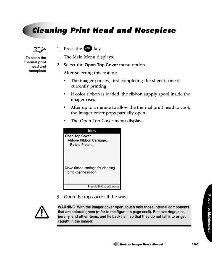
Pre
ve
ntiv
e M
ain
ten
an
ce
.
1. Press the key.
The Main Menu displays.
2. Select the Open Top Cover menu option.
After selecting this option:
• The imager pauses, first completing the sheet if one is currently printing.
• If color ribbon is loaded, the ribbon supply spool inside the imager rises.
• After up to a minute to allow the thermal print head to cool, the imager cover pops partially open.
• The Open Top Cover menu displays.
3. Open the top cover all the way.
`äÉ~åáåÖ=mêáåí=eÉ~Ç=~åÇ=kçëÉéáÉÅÉ
Menu
Open Top Cover
�Move Ribbon Carriage...
Rotate Platen...
Move ribbon carriage for cleaning
or to change ribbon.
Press MENU to exit menus
WARNING With the imager cover open, touch only those internal components
that are colored green (refer to the figure on page xxxii). Remove rings, ties,
jewelry, and other items, and tie back hair, so that they do not fall into or get
caught in the imager.
8To clean the
thermal print
head and
nosepiece
MENU
Horizon Imager User’s Manual 10-3
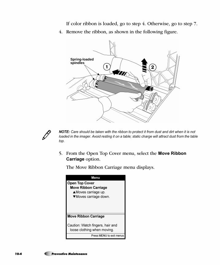
10
If color ribbon is loaded, go to step 4. Otherwise, go to step 7.
4. Remove the ribbon, as shown in the following figure.
NOTE: Care should be taken with the ribbon to protect it from dust and dirt when it is not
loaded in the imager. Avoid resting it on a table; static charge will attract dust from the table
top.
5. From the Open Top Cover menu, select the Move Ribbon
Carriage option.
The Move Ribbon Carriage menu displays.
Menu
Open Top Cover
Move Ribbon Carriage
�Moves carriage up.
�Moves carriage down.
Move Ribbon Carriage
Caution: Watch fingers, hair and
loose clothing when moving.
Press MENU to exit menus
Spring-loaded spindles
3
-4 Preventive Maintenance
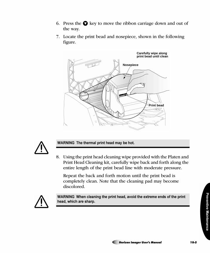
Pre
ve
ntiv
e M
ain
ten
an
ce
6. Press the key to move the ribbon carriage down and out of the way.
7. Locate the print bead and nosepiece, shown in the following figure.
8. Using the print head cleaning wipe provided with the Platen and Print Head Cleaning kit, carefully wipe back and forth along the entire length of the print bead line with moderate pressure.
Repeat the back and forth motion until the print bead is completely clean. Note that the cleaning pad may become discolored.
WARNING The thermal print head may be hot.
WARNING When cleaning the print head, avoid the extreme ends of the print
head, which are sharp.
�
Print bead
Nosepiece
Carefully wipe alongprint bead until clean
Horizon Imager User’s Manual 10-5
10
9. Clean any dust or other contaminants from the nosepiece.
10. Wait for the thermal print head and nosepiece to dry thoroughly.
If you need to reload the color ribbon, go to step 11. Otherwise go to step 13.
TIP: Cleaning the platen and donor guide bar while the top cover is open
If you want to clean the platen and donor guide bar while the imager is already open, refer
to steps 7 through 12 in the procedure in “Cleaning the Platen and Donor Guide Bar” on
page 10-8.
11. To reload the color ribbon, go to the Move Ribbon Carriage menu and press the key to move the ribbon carriage up so you can reload the ribbon.
CAUTION Use only the print head cleaning wipe when cleaning the thermal print
head. Also, do not touch the glass surface of the thermal print head with your fingers;
it could damage the print head. To avoid touching the glass surface, you may want to
wear gloves when cleaning the thermal print head.
CAUTION The thermal print head must be completely dry before attempting to use
the imager. Allowing the thermal print head to heat up again while still wet will damage
the thermal print head.
/
�
-6 Preventive Maintenance
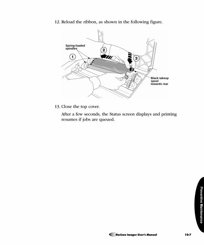
Pre
ve
ntiv
e M
ain
ten
an
ce
12. Reload the ribbon, as shown in the following figure.
13. Close the top cover.
After a few seconds, the Status screen displays and printing resumes if jobs are queued.
Spring-loaded spindles
Black takeupspooltowards rear
Horizon Imager User’s Manual 10-7
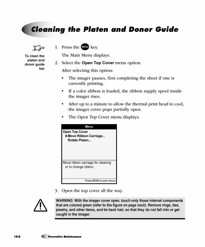
10
1. Press the key.
The Main Menu displays.
2. Select the Open Top Cover menu option.
After selecting this option:
• The imager pauses, first completing the sheet if one is currently printing.
• If a color ribbon is loaded, the ribbon supply spool inside the imager rises.
• After up to a minute to allow the thermal print head to cool, the imager cover pops partially open.
• The Open Top Cover menu displays.
3. Open the top cover all the way.
`äÉ~åáåÖ=íÜÉ=mä~íÉå=~åÇ=açåçê=dìáÇÉ=
Menu
Open Top Cover
�Move Ribbon Carriage...
Rotate Platen...
Move ribbon carriage for cleaning
or to change ribbon.
Press MENU to exit menus
WARNING With the imager cover open, touch only those internal components
that are colored green (refer to the figure on page xxxii). Remove rings, ties,
jewelry, and other items, and tie back hair, so that they do not fall into or get
caught in the imager.
8To clean the
platen and
donor guide
bar
MENU
-8 Preventive Maintenance
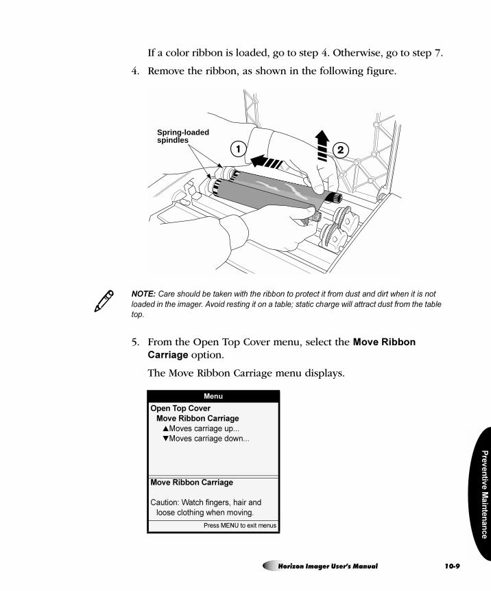
Pre
ve
ntiv
e M
ain
ten
an
ce
If a color ribbon is loaded, go to step 4. Otherwise, go to step 7.
4. Remove the ribbon, as shown in the following figure.
NOTE: Care should be taken with the ribbon to protect it from dust and dirt when it is not
loaded in the imager. Avoid resting it on a table; static charge will attract dust from the table
top.
5. From the Open Top Cover menu, select the Move Ribbon
Carriage option.
The Move Ribbon Carriage menu displays.
Menu
Open Top Cover
Move Ribbon Carriage
�Moves carriage up...
�Moves carriage down...
Move Ribbon Carriage
Caution: Watch fingers, hair and
loose clothing when moving.
Press MENU to exit menus
Spring-loaded spindles
3
Horizon Imager User’s Manual 10-9
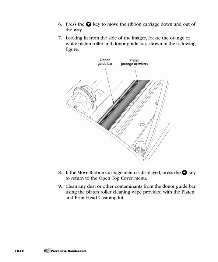
10
6. Press the key to move the ribbon carriage down and out of the way.
7. Looking in from the side of the imager, locate the orange or white platen roller and donor guide bar, shown in the following figure.
8. If the Move Ribbon Carriage menu is displayed, press the key to return to the Open Top Cover menu.
9. Clean any dust or other contaminants from the donor guide bar using the platen roller cleaning wipe provided with the Platen and Print Head Cleaning kit.
�
Platen (orange or white)
Donorguide bar
�
-10 Preventive Maintenance
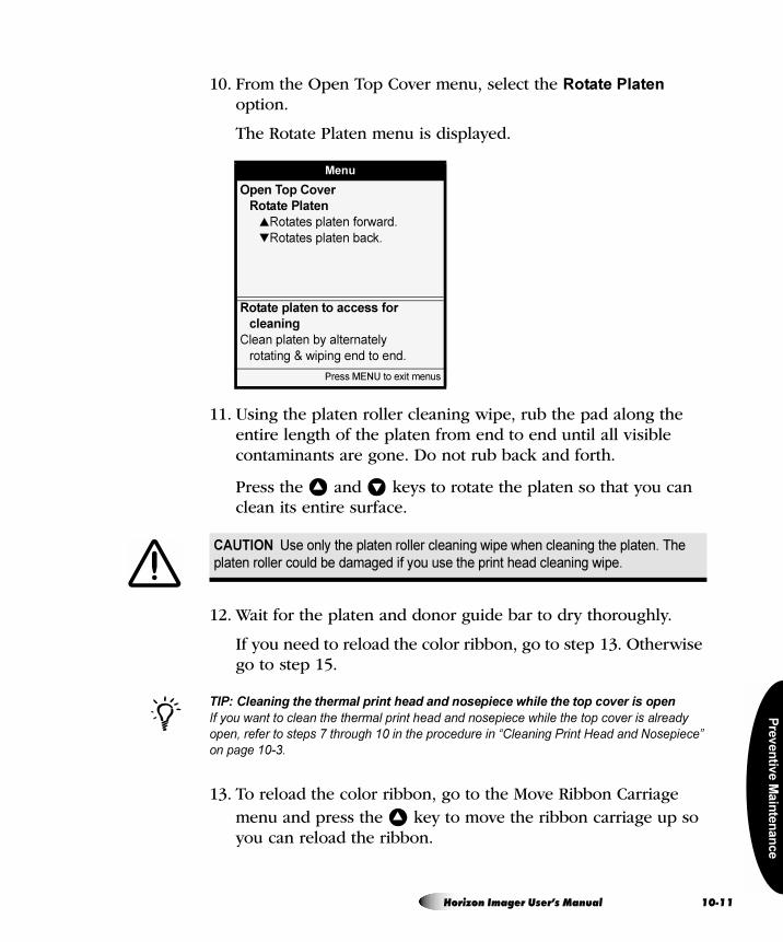
Pre
ve
ntiv
e M
ain
ten
an
ce
10. From the Open Top Cover menu, select the Rotate Platen option.
The Rotate Platen menu is displayed.
11. Using the platen roller cleaning wipe, rub the pad along the entire length of the platen from end to end until all visible contaminants are gone. Do not rub back and forth.
Press the and keys to rotate the platen so that you can clean its entire surface.
12. Wait for the platen and donor guide bar to dry thoroughly.
If you need to reload the color ribbon, go to step 13. Otherwise go to step 15.
TIP: Cleaning the thermal print head and nosepiece while the top cover is open
If you want to clean the thermal print head and nosepiece while the top cover is already
open, refer to steps 7 through 10 in the procedure in “Cleaning Print Head and Nosepiece”
on page 10-3.
13. To reload the color ribbon, go to the Move Ribbon Carriage menu and press the key to move the ribbon carriage up so you can reload the ribbon.
Menu
Open Top Cover
Rotate Platen
�Rotates platen forward.
�Rotates platen back.
Rotate platen to access for
cleaning
Clean platen by alternately
rotating & wiping end to end.
Press MENU to exit menus
CAUTION Use only the platen roller cleaning wipe when cleaning the platen. The
platen roller could be damaged if you use the print head cleaning wipe.
� �
/
�
Horizon Imager User’s Manual 10-11
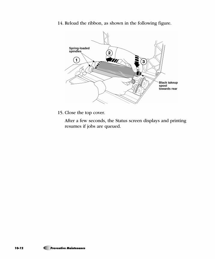
10
14. Reload the ribbon, as shown in the following figure.
15. Close the top cover.
After a few seconds, the Status screen displays and printing resumes if jobs are queued.
Spring-loaded spindles
Black takeupspooltowards rear
-12 Preventive Maintenance
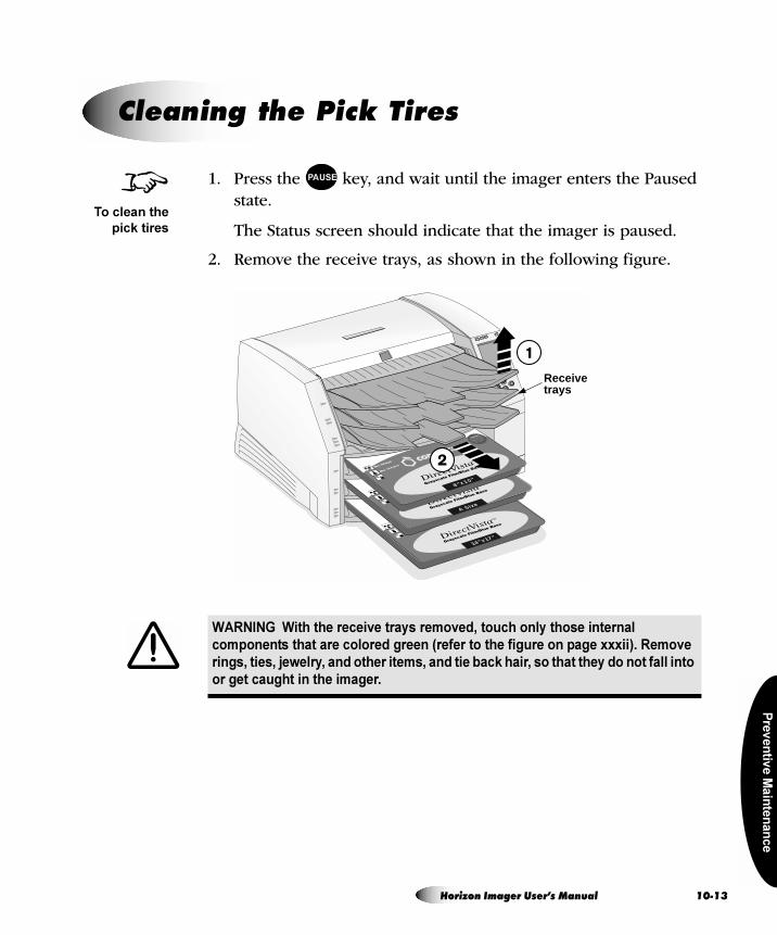
Pre
ve
ntiv
e M
ain
ten
an
ce
1. Press the key, and wait until the imager enters the Paused state.
The Status screen should indicate that the imager is paused.
2. Remove the receive trays, as shown in the following figure.
`äÉ~åáåÖ=íÜÉ=máÅâ=qáêÉë
WARNING With the receive trays removed, touch only those internal
components that are colored green (refer to the figure on page xxxii). Remove
rings, ties, jewelry, and other items, and tie back hair, so that they do not fall into
or get caught in the imager.
8To clean the
pick tires
PAUSE
14"x17"
A Size
8"x10"
Receivetrays
Horizon Imager User’s Manual 10-13
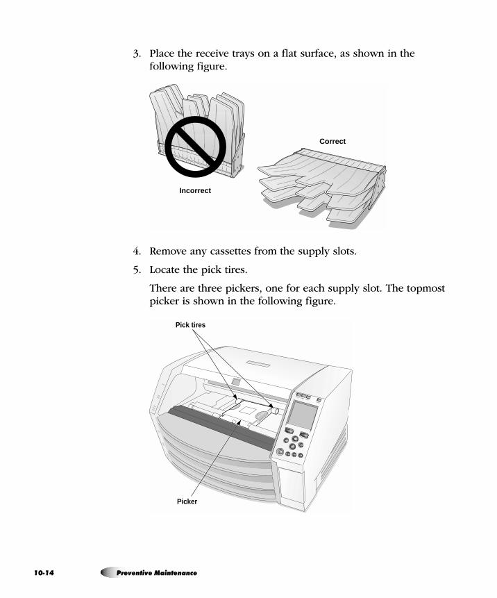
10
3. Place the receive trays on a flat surface, as shown in the following figure.
4. Remove any cassettes from the supply slots.
5. Locate the pick tires.
There are three pickers, one for each supply slot. The topmost picker is shown in the following figure.
Incorrect
Correct
Pick tires
Picker
-14 Preventive Maintenance
Pre
ve
ntiv
e M
ain
ten
an
ce
6. Wipe around each tire with the platen roller cleaning wipe that is provided with the Platen and Print Head Cleaning kit.
Note that the cleaning wipe may become discolored.
7. Wait for the pick tires to dry thoroughly.
8. Replace the receive trays and any media cassettes that were removed.
After a few seconds, the Status screen displays and printing resumes if jobs are queued.
1. Press the key, and wait until the imager enters the Paused state.
The Status screen should indicate that the imager is paused.
2. Remove any cassette currently in supply slot 1, and make sure that the receive trays are in and the top cover is closed.
3. Press the key.
The Main Menu displays.
4. Select the following options:
Utilities
Clean Barcode Reader
Instructions for cleaning the barcode reader are displayed.
CAUTION Use only the platen roller cleaning wipe when cleaning the pick tires. The
tires could be damaged if you use the print head cleaning wipe.
CAUTION Do not touch the pick tires (which may be white or green); body oils from
your fingers are hard to remove and could eventually damage the tires.
`äÉ~åáåÖ=íÜÉ=_~êÅçÇÉ=oÉ~ÇÉê=táåÇçï
8To clean the
barcode
reader window
PAUSE
MENU
Horizon Imager User’s Manual 10-15
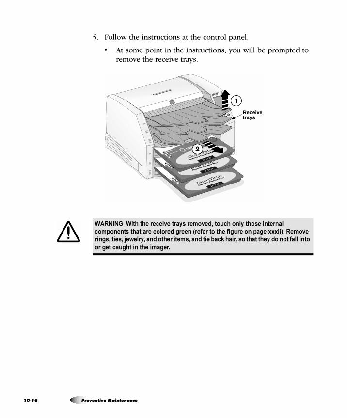
10
5. Follow the instructions at the control panel.
• At some point in the instructions, you will be prompted to remove the receive trays.
WARNING With the receive trays removed, touch only those internal
components that are colored green (refer to the figure on page xxxii). Remove
rings, ties, jewelry, and other items, and tie back hair, so that they do not fall into
or get caught in the imager.
14"x17"
A Size
8"x10"
Receivetrays
-16 Preventive Maintenance
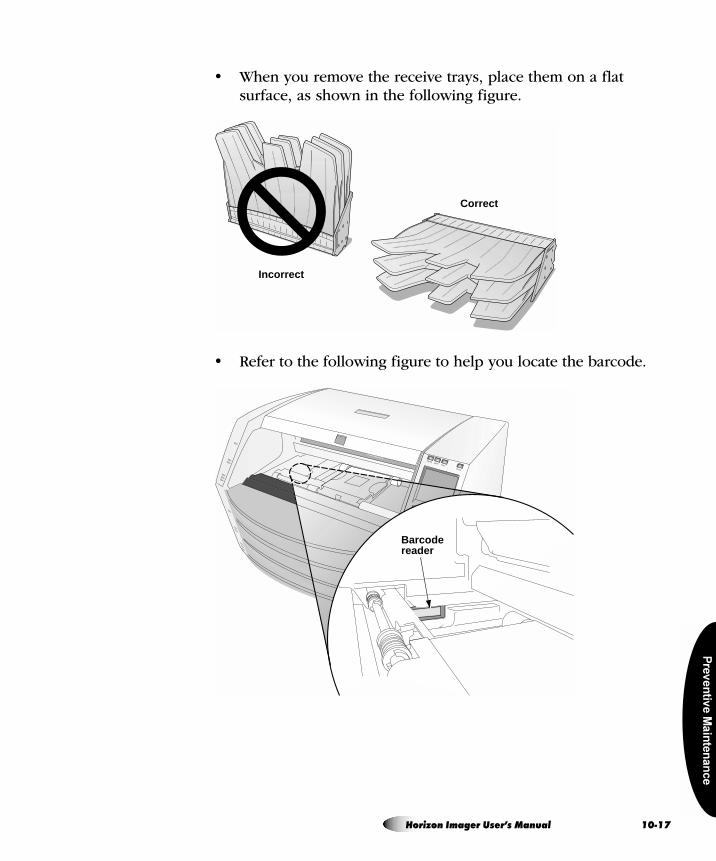
Pre
ve
ntiv
e M
ain
ten
an
ce
• When you remove the receive trays, place them on a flat surface, as shown in the following figure.
• Refer to the following figure to help you locate the barcode.
Incorrect
Correct
Barcodereader
Horizon Imager User’s Manual 10-17
10
• When prompted to clean the barcode reader, use one of the cleaning swabs provided with the Barcode Reader Cleaning Kit and rub across the barcode reader window until all dust and other contaminants are removed.
• At some point in the instructions, you will be prompted to replace the receive trays and any supply cassettes.
When you have completed the cleaning instructions, the Status screen displays and printing resumes if jobs are queued.
It is important to periodically clean components on the Horizon imager to keep them free of dust and debris.
`äÉ~åáåÖ=íÜÉ=^êÉ~=^êçìåÇ=íÜÉ=fã~ÖÉê
Clean the area around and under the imager to keep dust out of the cooling fans.
`äÉ~åáåÖ=íÜÉ=oÉÅÉáîÉ=qê~óë
Remove the receive trays. Using a platen roller wipe (refer to “Horizon Cleaning Kits” on page 10-2), clean the receive trays of any dust or debris. Use compressed air to blow inside the sheet metal at the inside bottom of the receive trays—referred to as the hide track—to remove any dust, then wipe the trays. (When printing a ChromaVista sheet, the imager advances the unfinished sheet into the hide track for all but the final color pass).
CAUTION Use only cleaning swabs from a Barcode Reader Cleaning Kit.
dÉåÉê~ä=`äÉ~åáåÖ=mêçÅÉÇìêÉë
-18 Preventive Maintenance
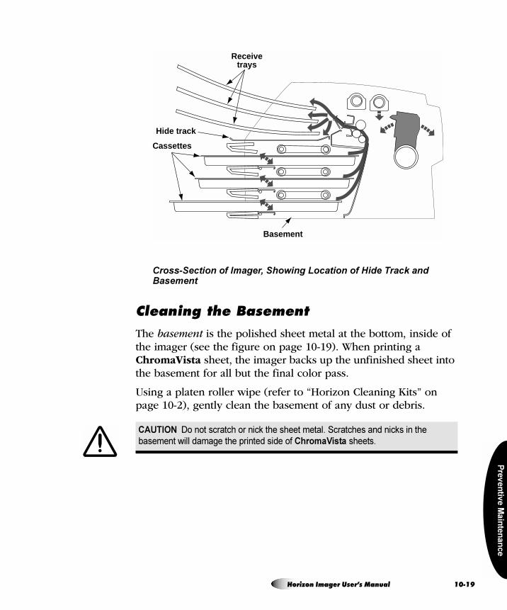
Pre
ve
ntiv
e M
ain
ten
an
ce
Cross-Section of Imager, Showing Location of Hide Track and Basement
`äÉ~åáåÖ=íÜÉ=_~ëÉãÉåí
The basement is the polished sheet metal at the bottom, inside of the imager (see the figure on page 10-19). When printing a ChromaVista sheet, the imager backs up the unfinished sheet into the basement for all but the final color pass.
Using a platen roller wipe (refer to “Horizon Cleaning Kits” on page 10-2), gently clean the basement of any dust or debris.
CAUTION Do not scratch or nick the sheet metal. Scratches and nicks in the
basement will damage the printed side of ChromaVista sheets.
Receivetrays
Cassettes
Hide track
Basement
Horizon Imager User’s Manual 10-19

Ca
libra
tion
= NN`~äáÄê~íáçåThere are several calibrations that are performed automatically, or can be performed manually, to optimize the image quality on printed sheets given variations in media and operating conditions:
• Film calibration is performed automatically by the imager when a DirectVista grayscale film cassette is inserted into the imager for the first time. You can also perform this calibration manually.
• Internal densitometer calibration allows you to recalibrate the imager’s internal densitometer, which is used to read optical densities when a DirectVista grayscale film calibration is performed.
• Thermal print head calibration creates a characterization of the thermal print head to compensate for non-uniformities in the imaging properties of the print head.
• Print length calibration can be performed to correct for images running off or printing short of the bottom of a sheet.
Only the film calibration procedure is covered in this manual. For more information about the other calibrations, and some of the other automatic compensations made by the imager, refer to the Horizon Imager Technical Manual.
Horizon Imager User’s Manual 11-1
11
Film calibration is the process of characterizing a given combination of imager and DirectVista grayscale film to allow the imager to compensate for imager-to-imager variation and supply cassette-to-cassette variation.
When a DirectVista grayscale film cassette is loaded into the imager for the first time, the imager will print a test sheet and read that test sheet with the built-in densitometer, then recalibrate based on the results.
You can also perform a film calibration manually.
1. Press the key.
The Main Menu displays.
2. Select the following menu options:
Utilities
Film Calibrate
The Film Calibration menu displays, allowing you to choose the supply slot (referred to as Cassette 1, 2, or 3) in which the DirectVista grayscale film cassette is loaded.
3. Select the appropriate supply slot, then press the key.
The imager prints a test sheet, recalibrating that cassette based on the result.
NOTE: If the selected supply slot does not have a DirectVista grayscale film cassette
loaded, the calibration will not run.
cáäã=`~äáÄê~íáçå=EaáêÉÅísáëí~=cáäã=låäóF
8To perform a
film
calibration
MENU
ENTER
3
-2 Calibration
Tro
ub
les
ho
otin
g
= NOqêçìÄäÉëÜççíáåÖ
`çåíêçä=m~åÉä
The control panel display shows the imager’s operating status. The control panel also has ALERT and FAULT indicators, which light when the imager needs attention or an error occurs.
For additional information on how to interpret control panel status messages and indicators, refer to “Troubleshooting Tables” on page 12-2.
bêêçê=içÖ
The imager logs error messages to a log file. You can view the 100 most recent messages using the Error Log function. To view logged error messages, refer to “Viewing Logged Error Messages” on page 12-28.
låäáåÉ=eÉäé=Ñçê=aáëéä~óÉÇ=jÉëë~ÖÉë
You can display help text for any of the messages displayed in the Status window. Simply move the selector arrow to the message for
which you want further explanation, then press the key.
pçìêÅÉë=çÑ=pí~íìë=fåÑçêã~íáçå
HELP
Horizon Imager User’s Manual 12-1
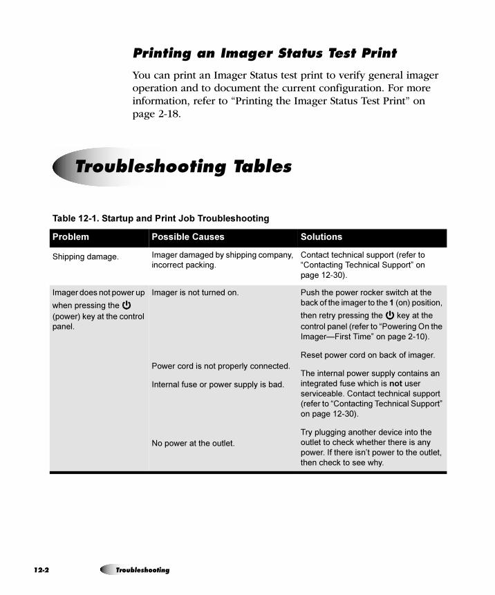
12
mêáåíáåÖ=~å=fã~ÖÉê=pí~íìë=qÉëí=mêáåí
You can print an Imager Status test print to verify general imager operation and to document the current configuration. For more information, refer to “Printing the Imager Status Test Print” on page 2-18.
qêçìÄäÉëÜççíáåÖ=q~ÄäÉë
Table 12-1. Startup and Print Job Troubleshooting
Problem Possible Causes Solutions
Shipping damage. Imager damaged by shipping company,
incorrect packing.
Contact technical support (refer to
“Contacting Technical Support” on
page 12-30).
Imager does not power up
when pressing the
(power) key at the control
panel.
Imager is not turned on.
Power cord is not properly connected.
Internal fuse or power supply is bad.
No power at the outlet.
Push the power rocker switch at the
back of the imager to the 1 (on) position,
then retry pressing the key at the
control panel (refer to “Powering On the
Imager—First Time” on page 2-10).
Reset power cord on back of imager.
The internal power supply contains an
integrated fuse which is not user
serviceable. Contact technical support
(refer to “Contacting Technical Support”
on page 12-30).
Try plugging another device into the
outlet to check whether there is any
power. If there isn’t power to the outlet,
then check to see why.
-2 Troubleshooting
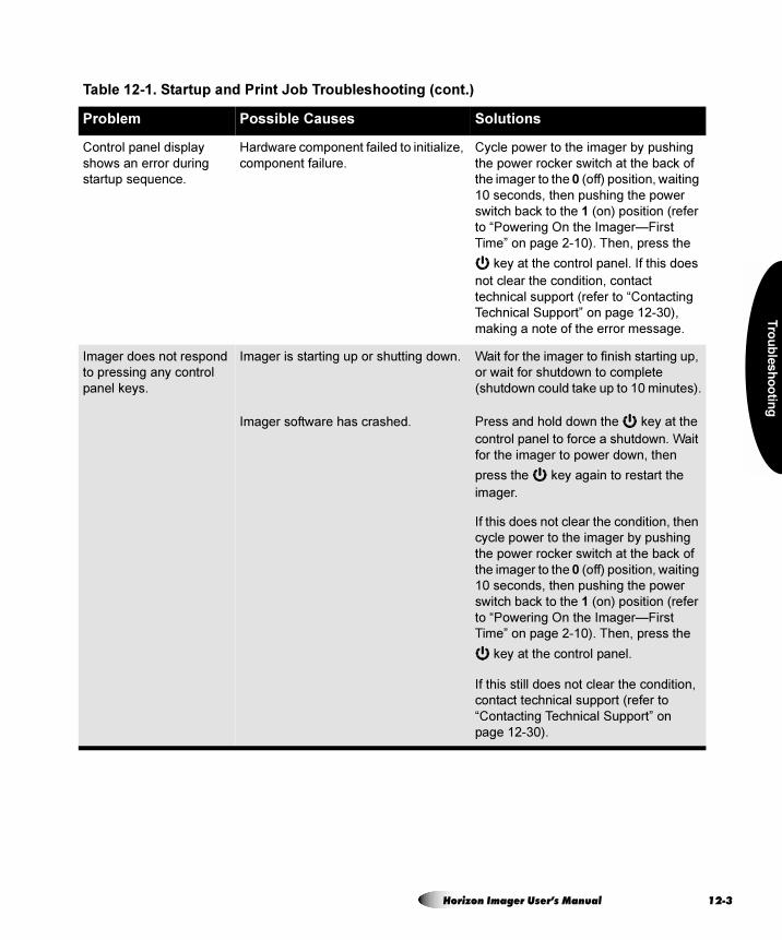
Tro
ub
les
ho
otin
g
Control panel display
shows an error during
startup sequence.
Hardware component failed to initialize,
component failure.
Cycle power to the imager by pushing
the power rocker switch at the back of
the imager to the 0 (off) position, waiting
10 seconds, then pushing the power
switch back to the 1 (on) position (refer
to “Powering On the Imager—First
Time” on page 2-10). Then, press the
key at the control panel. If this does
not clear the condition, contact
technical support (refer to “Contacting
Technical Support” on page 12-30),
making a note of the error message.
Imager does not respond
to pressing any control
panel keys.
Imager is starting up or shutting down.
Imager software has crashed.
Wait for the imager to finish starting up,
or wait for shutdown to complete
(shutdown could take up to 10 minutes).
Press and hold down the key at the
control panel to force a shutdown. Wait
for the imager to power down, then
press the key again to restart the
imager.
If this does not clear the condition, then
cycle power to the imager by pushing
the power rocker switch at the back of
the imager to the 0 (off) position, waiting
10 seconds, then pushing the power
switch back to the 1 (on) position (refer
to “Powering On the Imager—First
Time” on page 2-10). Then, press the
key at the control panel.
If this still does not clear the condition,
contact technical support (refer to
“Contacting Technical Support” on
page 12-30).
Table 12-1. Startup and Print Job Troubleshooting (cont.)
Problem Possible Causes Solutions
Horizon Imager User’s Manual 12-3
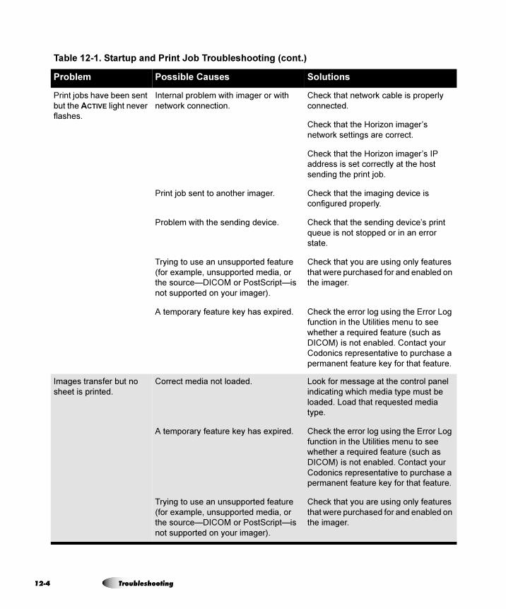
12
Print jobs have been sent
but the ACTIVE light never
flashes.
Internal problem with imager or with
network connection.
Print job sent to another imager.
Problem with the sending device.
Trying to use an unsupported feature
(for example, unsupported media, or
the source—DICOM or PostScript—is
not supported on your imager).
A temporary feature key has expired.
Check that network cable is properly
connected.
Check that the Horizon imager’s
network settings are correct.
Check that the Horizon imager’s IP
address is set correctly at the host
sending the print job.
Check that the imaging device is
configured properly.
Check that the sending device’s print
queue is not stopped or in an error
state.
Check that you are using only features
that were purchased for and enabled on
the imager.
Check the error log using the Error Log
function in the Utilities menu to see
whether a required feature (such as
DICOM) is not enabled. Contact your
Codonics representative to purchase a
permanent feature key for that feature.
Images transfer but no
sheet is printed.
Correct media not loaded.
A temporary feature key has expired.
Trying to use an unsupported feature
(for example, unsupported media, or
the source—DICOM or PostScript—is
not supported on your imager).
Look for message at the control panel
indicating which media type must be
loaded. Load that requested media
type.
Check the error log using the Error Log
function in the Utilities menu to see
whether a required feature (such as
DICOM) is not enabled. Contact your
Codonics representative to purchase a
permanent feature key for that feature.
Check that you are using only features
that were purchased for and enabled on
the imager.
Table 12-1. Startup and Print Job Troubleshooting (cont.)
Problem Possible Causes Solutions
-4 Troubleshooting
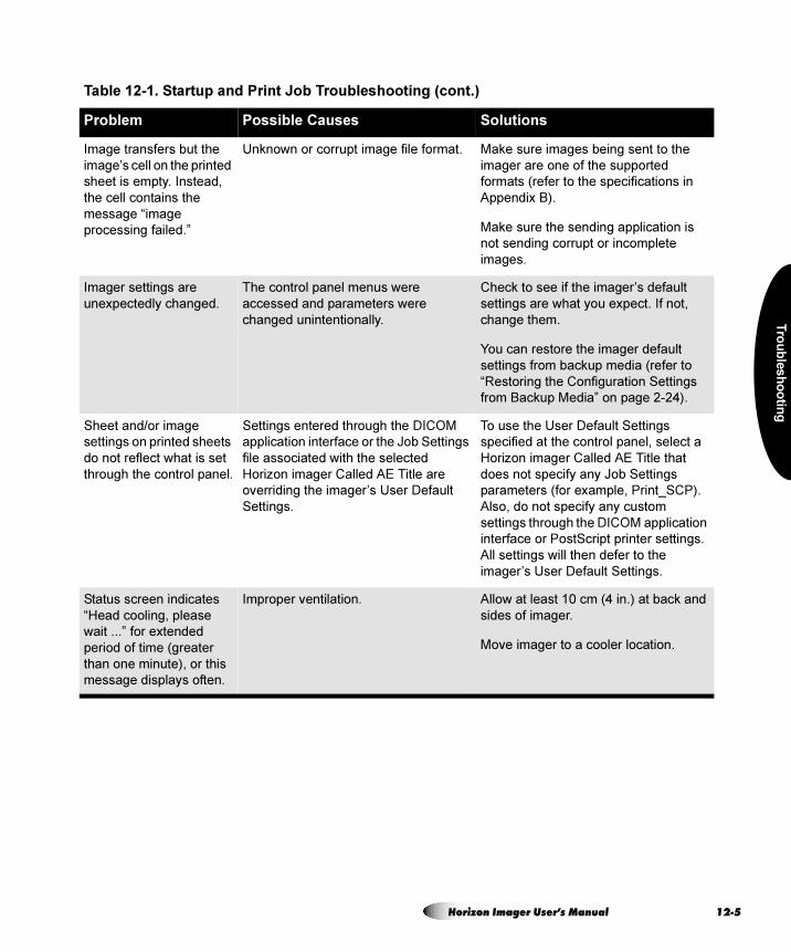
Tro
ub
les
ho
otin
g
Image transfers but the
image’s cell on the printed
sheet is empty. Instead,
the cell contains the
message “image
processing failed.”
Unknown or corrupt image file format. Make sure images being sent to the
imager are one of the supported
formats (refer to the specifications in
Appendix B).
Make sure the sending application is
not sending corrupt or incomplete
images.
Imager settings are
unexpectedly changed.
The control panel menus were
accessed and parameters were
changed unintentionally.
Check to see if the imager’s default
settings are what you expect. If not,
change them.
You can restore the imager default
settings from backup media (refer to
“Restoring the Configuration Settings
from Backup Media” on page 2-24).
Sheet and/or image
settings on printed sheets
do not reflect what is set
through the control panel.
Settings entered through the DICOM
application interface or the Job Settings
file associated with the selected
Horizon imager Called AE Title are
overriding the imager’s User Default
Settings.
To use the User Default Settings
specified at the control panel, select a
Horizon imager Called AE Title that
does not specify any Job Settings
parameters (for example, Print_SCP).
Also, do not specify any custom
settings through the DICOM application
interface or PostScript printer settings.
All settings will then defer to the
imager’s User Default Settings.
Status screen indicates
“Head cooling, please
wait ...” for extended
period of time (greater
than one minute), or this
message displays often.
Improper ventilation. Allow at least 10 cm (4 in.) at back and
sides of imager.
Move imager to a cooler location.
Table 12-1. Startup and Print Job Troubleshooting (cont.)
Problem Possible Causes Solutions
Horizon Imager User’s Manual 12-5
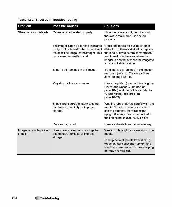
12
Table 12-2. Sheet Jam Troubleshooting
Problem Possible Causes Solutions
Sheet jams or misfeeds. Cassette is not seated properly.
The imager is being operated in an area
of high or low humidity that is outside of
the specified range for the imager. This
can cause the media to curl.
Sheet is still jammed in the imager.
Very dirty pick tires or platen.
Sheets are blocked or stuck together
due to heat, humidity, or improper
storage.
Receive tray is full.
Slide the cassette out, then back into
the slot to make sure it is seated
properly.
Check the media for curling or other
distortion. If there is distortion, replace
the media. Try to control temperature
and humidity in the area where the
imager is located, or move the imager to
a more suitable location.
If a sheet is still jammed in the imager,
remove it (refer to “Clearing a Sheet
Jam” on page 12-14).
Clean the platen (refer to “Cleaning the
Platen and Donor Guide Bar” on
page 10-8) and the pick tires (refer to
“Cleaning the Pick Tires” on
page 10-13).
Wearing rubber gloves, carefully fan the
media. To help prevent sheets from
sticking together, store cassettes
upright (the way they come packed in
their shipping boxes), not lying flat.
Remove sheets from the receive tray.
Imager is double-picking
sheets.
Sheets are blocked or stuck together
due to heat, humidity, or improper
storage.
Wearing rubber gloves, carefully fan the
media.
To help prevent sheets from sticking
together, store cassettes upright (the
way they come packed in their shipping
boxes), not lying flat.
-6 Troubleshooting
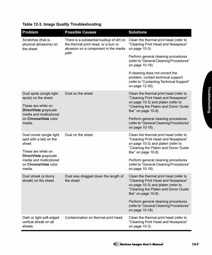
Tro
ub
les
ho
otin
g
Table 12-3. Image Quality Troubleshooting
Problem Possible Causes Solutions
Scratches (that is,
physical abrasions) on
the sheet.
There is a substantial buildup of dirt on
the thermal print head, or a burr or
abrasion on a component in the media
path.
Clean the thermal print head (refer to
“Cleaning Print Head and Nosepiece”
on page 10-3).
Perform general cleaning procedures
(refer to “General Cleaning Procedures”
on page 10-18).
If cleaning does not correct the
problem, contact technical support
(refer to “Contacting Technical Support”
on page 12-30).
Dust spots (single light
spots) on the sheet.
These are white on
DirectVista grayscale
media and multicolored
on ChromaVista color
media.
Dust on the sheet. Clean the thermal print head (refer to
“Cleaning Print Head and Nosepiece”
on page 10-3) and platen (refer to
“Cleaning the Platen and Donor Guide
Bar” on page 10-8).
Perform general cleaning procedures
(refer to “General Cleaning Procedures”
on page 10-18).
Dust comet (single light
spot with a tail) on the
sheet.
These are white on
DirectVista grayscale
media and multicolored
on ChromaVista color
media.
Dust on the sheet. Clean the thermal print head (refer to
“Cleaning Print Head and Nosepiece”
on page 10-3) and platen (refer to
“Cleaning the Platen and Donor Guide
Bar” on page 10-8).
Perform general cleaning procedures
(refer to “General Cleaning Procedures”
on page 10-18).
Dust streak (a blurry
streak) on the sheet.
Dust was dragged down the length of
the sheet.
Clean the thermal print head (refer to
“Cleaning Print Head and Nosepiece”
on page 10-3) and platen (refer to
“Cleaning the Platen and Donor Guide
Bar” on page 10-8).
Perform general cleaning procedures
(refer to “General Cleaning Procedures”
on page 10-18).
Dark or light soft-edged
vertical streak on all
sheets.
Contamination on thermal print head. Clean the thermal print head (refer to
“Cleaning Print Head and Nosepiece”
on page 10-3).
Horizon Imager User’s Manual 12-7
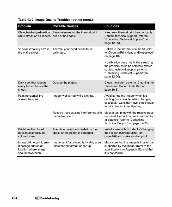
12
Clear, hard-edged vertical
white streak on all sheets.
Blown element on the thermal print
head or bad cable.
Need new thermal print head or cable.
Contact technical support (refer to
“Contacting Technical Support” on
page 12-30).
Vertical streaking across
the entire sheet.
Thermal print head needs to be
calibrated.
Calibrate the thermal print head (refer
to “Cleaning Print Head and Nosepiece”
on page 10-3).
If calibration does not fix the streaking,
the problem could be software related;
contact technical support (refer to
“Contacting Technical Support” on
page 12-30).
Dark spot that repeats
every few inches on the
sheet.
Dust on the platen. Clean the platen (refer to “Cleaning the
Platen and Donor Guide Bar” on
page 10-8).
Faint horizontal line
across the sheet.
Imager was jarred while printing.
Receive trays causing interference with
media transport.
Avoid jarring the imager when it is
printing (for example, when changing
cassettes). Consider moving the imager
to minimize accidental jarring.
Make a test print with the receive trays
removed. Contact technical support for
assistance (refer to “Contacting
Technical Support” on page 12-30).
Bright, multi-colored
horizontal streaks on
colored sheet.
The ribbon may be wrinkled on the
spool, or the ribbon is damaged.
Install a new ribbon [refer to “Changing
the Ribbon (ChromaVista)” on
page 4-8] and make another print.
Image did not print; error
message printed at
location where image
should have been.
Image sent for printing is invalid, in an
unsupported format, or corrupt.
Make sure that the image is in a format
supported by the imager (refer to the
specifications in Appendix B), and that
it is not corrupt.
Table 12-3. Image Quality Troubleshooting (cont.)
Problem Possible Causes Solutions
-8 Troubleshooting

Tro
ub
les
ho
otin
g
The message “Warning:
Image Decimated” is
printed in the corner of an
image.
The Image Warnings option has been
enabled, and the image has been
decimated. Decimation occurs if pixels
are removed from an image so that it
can fit in its cell area on the sheet.
If image decimation is acceptable
and you do not want the message to
print, disable the Decimation warning
(refer to Appendix D) and reprint the
image.
If image decimation is not
acceptable, specify a smaller size for
the image at the image source device or
pick a format that allows for a larger
image area on the sheet.
Table 12-4. Media Cassette and Ribbon Troubleshooting
Problem Possible Causes Solutions
Printed sheets are falling
from the imager.
Receive tray is full. Remove the sheets from the receive
tray.
The imager cannot read
the cassette barcode.
If the cassette is valid, the barcode label
may not be correctly positioned or the
barcode reader window may be dirty.
Try reinserting the cassette. If this does
not work, check the barcode label
position and/or clean the barcode
reader window (refer to “Cleaning the
Barcode Reader Window” on
page 10-15). If none of this works,
manually enter the barcode number
(refer to “Manually Entering a Cassette
Barcode” on page 12-26).
The imager indicates that
the barcode is invalid.
There is a problem with the cassette’s
barcode.
Contact your Codonics representative.
The imager indicates that
the media is
contaminated or that the
sheet count has been
exceeded.
Additional sheets were inserted into the
supply cassette beyond what was
originally packaged.
For quality control reasons, you cannot
add sheets to a supply cassette.
Table 12-3. Image Quality Troubleshooting (cont.)
Problem Possible Causes Solutions
Horizon Imager User’s Manual 12-9
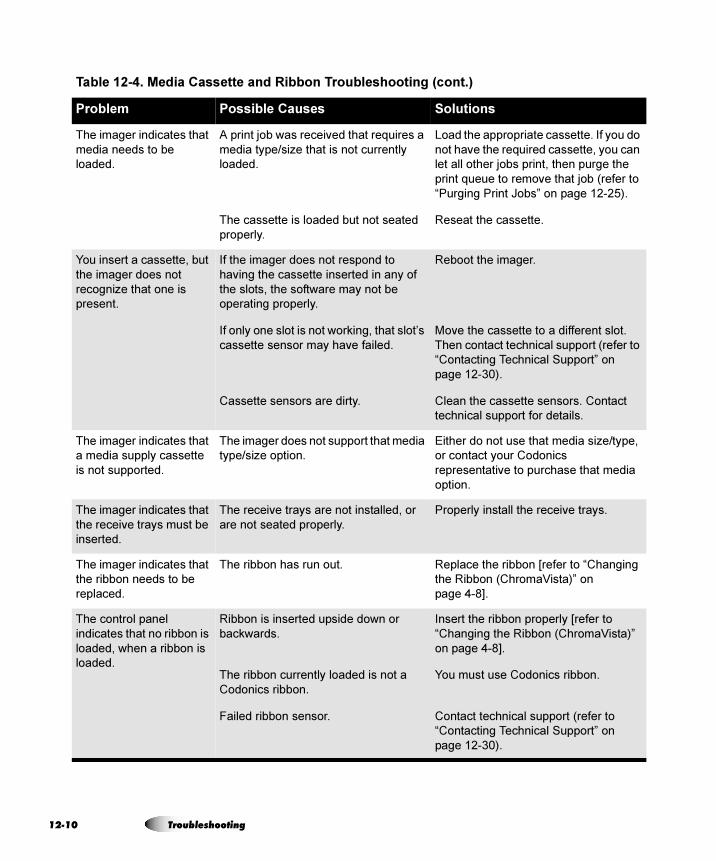
12
The imager indicates that
media needs to be
loaded.
A print job was received that requires a
media type/size that is not currently
loaded.
The cassette is loaded but not seated
properly.
Load the appropriate cassette. If you do
not have the required cassette, you can
let all other jobs print, then purge the
print queue to remove that job (refer to
“Purging Print Jobs” on page 12-25).
Reseat the cassette.
You insert a cassette, but
the imager does not
recognize that one is
present.
If the imager does not respond to
having the cassette inserted in any of
the slots, the software may not be
operating properly.
If only one slot is not working, that slot’s
cassette sensor may have failed.
Cassette sensors are dirty.
Reboot the imager.
Move the cassette to a different slot.
Then contact technical support (refer to
“Contacting Technical Support” on
page 12-30).
Clean the cassette sensors. Contact
technical support for details.
The imager indicates that
a media supply cassette
is not supported.
The imager does not support that media
type/size option.
Either do not use that media size/type,
or contact your Codonics
representative to purchase that media
option.
The imager indicates that
the receive trays must be
inserted.
The receive trays are not installed, or
are not seated properly.
Properly install the receive trays.
The imager indicates that
the ribbon needs to be
replaced.
The ribbon has run out. Replace the ribbon [refer to “Changing
the Ribbon (ChromaVista)” on
page 4-8].
The control panel
indicates that no ribbon is
loaded, when a ribbon is
loaded.
Ribbon is inserted upside down or
backwards.
The ribbon currently loaded is not a
Codonics ribbon.
Failed ribbon sensor.
Insert the ribbon properly [refer to
“Changing the Ribbon (ChromaVista)”
on page 4-8].
You must use Codonics ribbon.
Contact technical support (refer to
“Contacting Technical Support” on
page 12-30).
Table 12-4. Media Cassette and Ribbon Troubleshooting (cont.)
Problem Possible Causes Solutions
-10 Troubleshooting
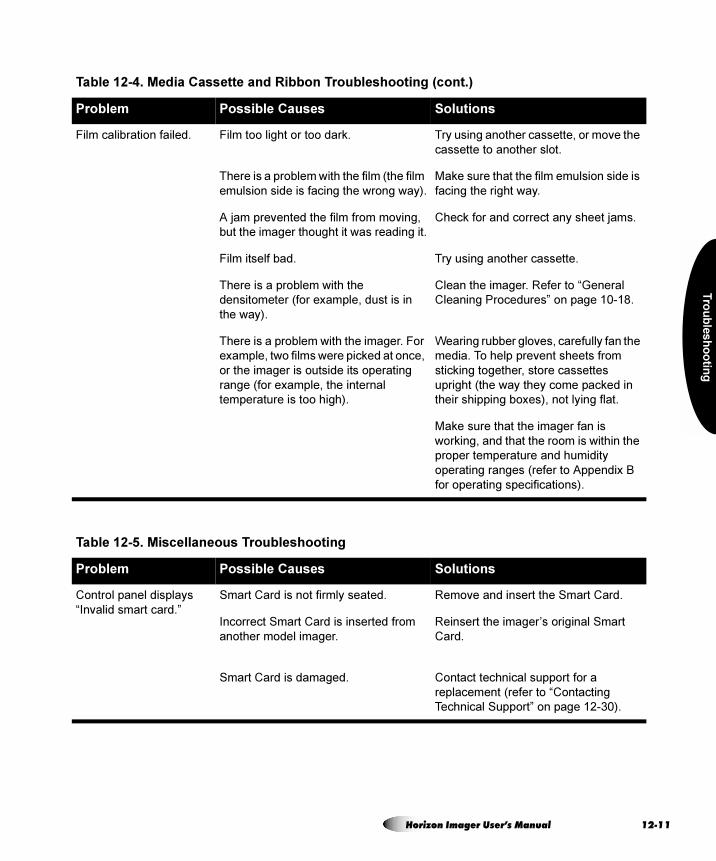
Tro
ub
les
ho
otin
g
Film calibration failed. Film too light or too dark.
There is a problem with the film (the film
emulsion side is facing the wrong way).
A jam prevented the film from moving,
but the imager thought it was reading it.
Film itself bad.
There is a problem with the
densitometer (for example, dust is in
the way).
There is a problem with the imager. For
example, two films were picked at once,
or the imager is outside its operating
range (for example, the internal
temperature is too high).
Try using another cassette, or move the
cassette to another slot.
Make sure that the film emulsion side is
facing the right way.
Check for and correct any sheet jams.
Try using another cassette.
Clean the imager. Refer to “General
Cleaning Procedures” on page 10-18.
Wearing rubber gloves, carefully fan the
media. To help prevent sheets from
sticking together, store cassettes
upright (the way they come packed in
their shipping boxes), not lying flat.
Make sure that the imager fan is
working, and that the room is within the
proper temperature and humidity
operating ranges (refer to Appendix B
for operating specifications).
Table 12-5. Miscellaneous Troubleshooting
Problem Possible Causes Solutions
Control panel displays
“Invalid smart card.”
Smart Card is not firmly seated.
Incorrect Smart Card is inserted from
another model imager.
Smart Card is damaged.
Remove and insert the Smart Card.
Reinsert the imager’s original Smart
Card.
Contact technical support for a
replacement (refer to “Contacting
Technical Support” on page 12-30).
Table 12-4. Media Cassette and Ribbon Troubleshooting (cont.)
Problem Possible Causes Solutions
Horizon Imager User’s Manual 12-11
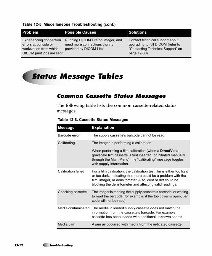
12
`çããçå=`~ëëÉííÉ=pí~íìë=jÉëë~ÖÉë
The following table lists the common cassette-related status messages.
Experiencing connection
errors at console or
workstation from which
DICOM print jobs are sent
Running DICOM Lite on imager, and
need more connections than is
provided by DICOM Lite.
Contact technical support about
upgrading to full DICOM (refer to
“Contacting Technical Support” on
page 12-30).
Table 12-5. Miscellaneous Troubleshooting (cont.)
Problem Possible Causes Solutions
pí~íìë=jÉëë~ÖÉ=q~ÄäÉë
Table 12-6. Cassette Status Messages
Message Explanation
Barcode error The supply cassette’s barcode cannot be read.
Calibrating The imager is performing a calibration.
When performing a film calibration (when a DirectVista
grayscale film cassette is first inserted, or initiated manually
through the Main Menu), the “calibrating” message toggles
with supply information.
Calibration failed For a film calibration, the calibration test film is either too light
or too dark, indicating that there could be a problem with the
film, imager, or densitometer. Also, dust or dirt could be
blocking the densitometer and affecting valid readings.
Checking cassette The imager is reading the supply cassette’s barcode, or waiting
to read the barcode (for example, if the top cover is open, bar
code will not be read).
Media contaminated The media in loaded supply cassette does not match the
information from the cassette’s barcode. For example,
cassette has been loaded with additional unknown sheets.
Media Jam A jam as occurred with media from the indicated cassette.
-12 Troubleshooting
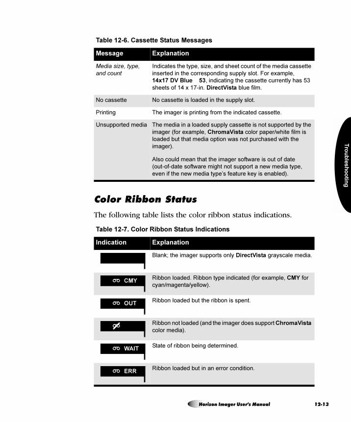
Tro
ub
les
ho
otin
g
`çäçê=oáÄÄçå=pí~íìë
The following table lists the color ribbon status indications.
Media size, type, and count
Indicates the type, size, and sheet count of the media cassette
inserted in the corresponding supply slot. For example,
14x17 DV Blue 53, indicating the cassette currently has 53
sheets of 14 x 17-in. DirectVista blue film.
No cassette No cassette is loaded in the supply slot.
Printing The imager is printing from the indicated cassette.
Unsupported media The media in a loaded supply cassette is not supported by the
imager (for example, ChromaVista color paper/white film is
loaded but that media option was not purchased with the
imager).
Also could mean that the imager software is out of date
(out-of-date software might not support a new media type,
even if the new media type’s feature key is enabled).
Table 12-7. Color Ribbon Status Indications
Indication Explanation
Blank; the imager supports only DirectVista grayscale media.
Ribbon loaded. Ribbon type indicated (for example, CMY for
cyan/magenta/yellow).
Ribbon loaded but the ribbon is spent.
Ribbon not loaded (and the imager does support ChromaVista
color media).
State of ribbon being determined.
Ribbon loaded but in an error condition.
Table 12-6. Cassette Status Messages
Message Explanation
CMY
OUT
WAIT
ERR
Horizon Imager User’s Manual 12-13
12
A sheet may occasionally get jammed in the imager. If this happens:
• The imager goes offline.
• A fault message displays.
• The area at which the jam occurred is indicated in the Status window. (There may be intermediate messages, such as “Media jam occurred, please wait...,” while the imager is preparing for the jam to be cleared.)
• The FAULT indicator lights.
• An audible fault beep sounds until you clear the jammed sheet (or press any key).
• The imager pauses for up to a minute while the thermal print head cools, then partially pops open the top cover.
The message in the Status screen will be one of the following:
• Clear jam from cassette X. This message indicates that the sheet has jammed while being picked from the cassette and is:
- Still in the cassette (the sheet never left the cassette, possibly because the pick tires are dirty and could not grab the sheet).
- Stuck in the lower part of the imager (refer to the figure on page 12-15).
• Clear jam from the printing area. This message indicates that the sheet has jammed while printing and is:
- Stuck in the lower part of the imager.
- Stuck in the upper part of the imager. The upper part of the imager includes the thermal print head/platen area, the capstan/pinch roller area, the diverter, and the receive trays.
`äÉ~êáåÖ=~=pÜÉÉí=g~ã
-14 Troubleshooting
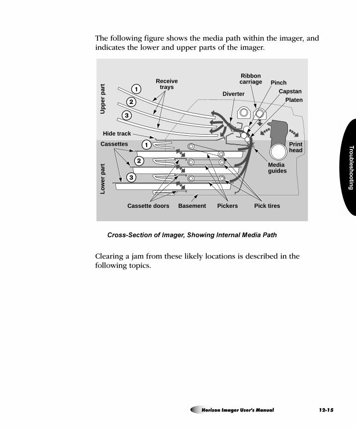
Tro
ub
les
ho
otin
g
The following figure shows the media path within the imager, and indicates the lower and upper parts of the imager.
Cross-Section of Imager, Showing Internal Media Path
Clearing a jam from these likely locations is described in the following topics.
Diverter
Ribboncarriage
Printhead
PinchCapstan
Platen
Mediaguides
Receivetrays
Cassettes
Hide track
Basement Pickers Pick tiresCassette doors
Up
per
par
tL
ow
er p
art
Horizon Imager User’s Manual 12-15
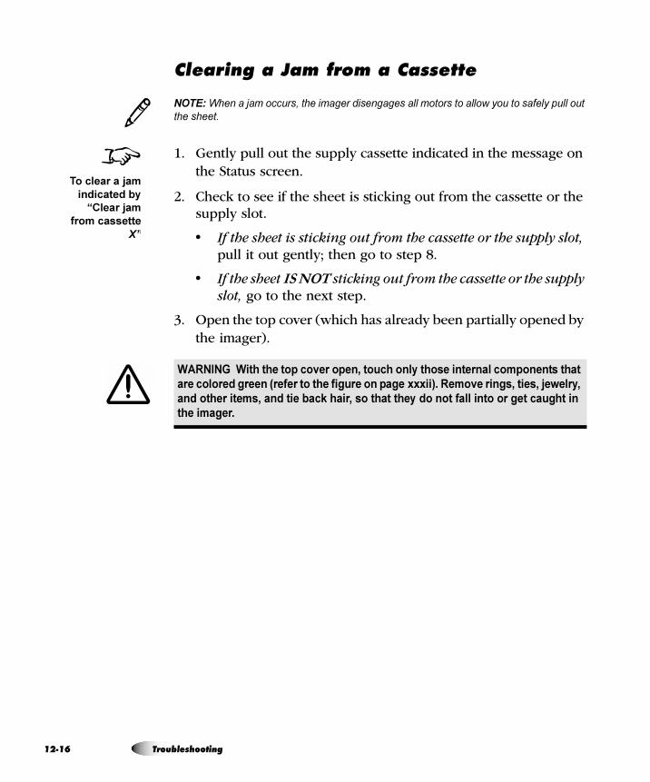
12
`äÉ~êáåÖ=~=g~ã=Ñêçã=~=`~ëëÉííÉ
NOTE: When a jam occurs, the imager disengages all motors to allow you to safely pull out
the sheet.
1. Gently pull out the supply cassette indicated in the message on the Status screen.
2. Check to see if the sheet is sticking out from the cassette or the supply slot.
• If the sheet is sticking out from the cassette or the supply slot, pull it out gently; then go to step 8.
• If the sheet IS NOT sticking out from the cassette or the supply slot, go to the next step.
3. Open the top cover (which has already been partially opened by the imager).
WARNING With the top cover open, touch only those internal components that
are colored green (refer to the figure on page xxxii). Remove rings, ties, jewelry,
and other items, and tie back hair, so that they do not fall into or get caught in
the imager.
3
8To clear a jam
indicated by
“Clear jam
from cassette
X”
-16 Troubleshooting
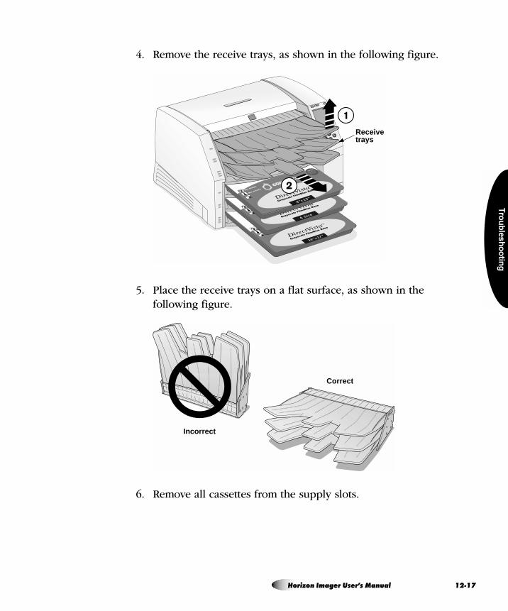
Tro
ub
les
ho
otin
g
4. Remove the receive trays, as shown in the following figure.
5. Place the receive trays on a flat surface, as shown in the following figure.
6. Remove all cassettes from the supply slots.
14"x17"
A Size
8"x10"
Receivetrays
Incorrect
Correct
Horizon Imager User’s Manual 12-17
12
7. Look down in the imager to locate either the trailing or leading edge of the sheet:
• If you see the trailing edge in the lower part of the imager, lift the pickers (refer to the figure on page 12-15) and gently remove the sheet, or push the corresponding cassette flap down and feed the sheet back out the supply slot opening.
• If you see the leading edge in the upper part of the imager, gently pull the sheet out through the top of the imager.
8. Discard the sheet.
9. If the top cover is open, close it.
After a few seconds, the Status screen displays and printing resumes if jobs are queued.
CAUTION Do not touch the pick tires (which may be white or green); body oils from
your fingers are hard to remove and could eventually damage the tires.
CAUTION To avoid damaging internal components, use care when removing a sheet
from the media path in the upper part of the imager.
CAUTION Never put a sheet back in the cassette. Dust or oil from your finger will
affect the image quality.
-18 Troubleshooting
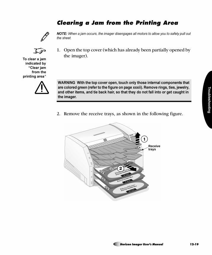
Tro
ub
les
ho
otin
g
`äÉ~êáåÖ=~=g~ã=Ñêçã=íÜÉ=mêáåíáåÖ=^êÉ~
NOTE: When a jam occurs, the imager disengages all motors to allow you to safely pull out
the sheet.
1. Open the top cover (which has already been partially opened by the imager).
2. Remove the receive trays, as shown in the following figure.
WARNING With the top cover open, touch only those internal components that
are colored green (refer to the figure on page xxxii). Remove rings, ties, jewelry,
and other items, and tie back hair, so that they do not fall into or get caught in
the imager.
3
8To clear a jam
indicated by
“Clear jam
from the
printing area”
14"x17"
A Size
8"x10"
Receivetrays
Horizon Imager User’s Manual 12-19
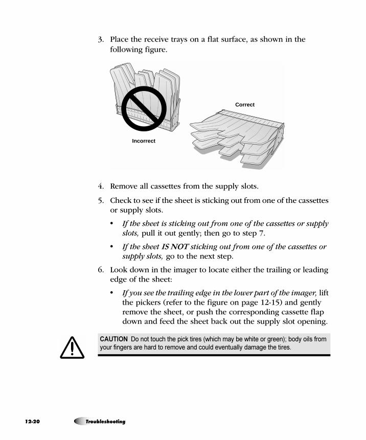
12
3. Place the receive trays on a flat surface, as shown in the following figure.
4. Remove all cassettes from the supply slots.
5. Check to see if the sheet is sticking out from one of the cassettes or supply slots.
• If the sheet is sticking out from one of the cassettes or supply slots, pull it out gently; then go to step 7.
• If the sheet IS NOT sticking out from one of the cassettes or supply slots, go to the next step.
6. Look down in the imager to locate either the trailing or leading edge of the sheet:
• If you see the trailing edge in the lower part of the imager, lift the pickers (refer to the figure on page 12-15) and gently remove the sheet, or push the corresponding cassette flap down and feed the sheet back out the supply slot opening.
CAUTION Do not touch the pick tires (which may be white or green); body oils from
your fingers are hard to remove and could eventually damage the tires.
Incorrect
Correct
-20 Troubleshooting
Tro
ub
les
ho
otin
g
• If you see the leading edge in the upper part of the imager, gently pull the sheet out through the top of the imager.
NOTE: To access the jammed sheet, you may need to remove the ribbon and/or move the
ribbon carriage down using the Load/Remove Ribbon option in the Open Top Cover
menu.
• If the leading edge is through the diverter, gently pull the sheet out through the diverter (refer to the figure on page 12-15).
7. Discard the sheet.
8. If the top cover is open, close it.
After a few seconds, the Status screen displays and printing resumes if jobs are queued.
CAUTION To avoid damaging internal components, use care when removing a sheet
from the media path in the upper part of the imager.
CAUTION Never put a sheet back in the cassette. Dust or oil from your finger will
affect the image quality.
3
Horizon Imager User’s Manual 12-21
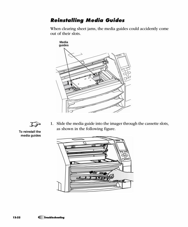
12
oÉáåëí~ääáåÖ=jÉÇá~=dìáÇÉë
When clearing sheet jams, the media guides could accidently come out of their slots.
1. Slide the media guide into the imager through the cassette slots, as shown in the following figure.
Media guides
8To reinstall the
media guides
-22 Troubleshooting
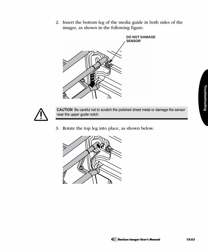
Tro
ub
les
ho
otin
g
2. Insert the bottom leg of the media guide in both sides of the imager, as shown in the following figure.
3. Rotate the top leg into place, as shown below.
CAUTION Be careful not to scratch the polished sheet metal or damage the sensor
near the upper guide notch.
DO NOT DAMAGESENSOR
Horizon Imager User’s Manual 12-23
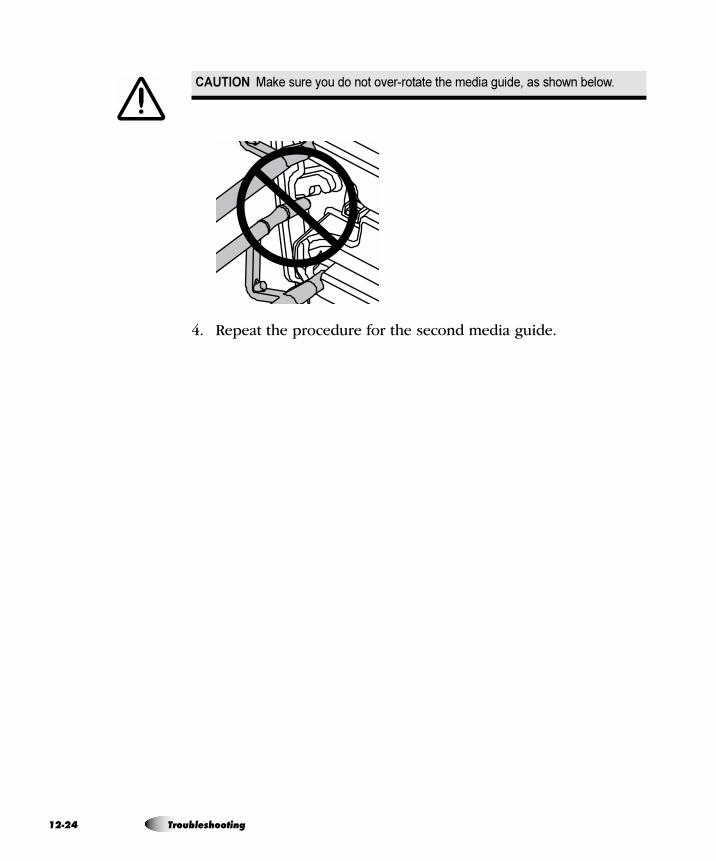
12
4. Repeat the procedure for the second media guide.
CAUTION Make sure you do not over-rotate the media guide, as shown below.
-24 Troubleshooting
Tro
ub
les
ho
otin
g
If necessary, you can purge all queued print jobs in the imager. For example, you may want to purge print jobs if you have a large print job that you decided not to print.
1. Press the key.
The Main Menu displays.
2. Select the following menu options:
Utilities
Purge Print Jobs
You are prompted to confirm the purge operation.
3. To continue with the purge, press the key.
All print jobs are purged, and the Utilities menu is displayed again.
mìêÖáåÖ=mêáåí=gçÄë
CAUTION Use care when running the Purge Print Jobs function. This function will
purge other users’ print jobs as well as yours.
8To purge all
queued print
jobs
MENU
ENTER
Horizon Imager User’s Manual 12-25
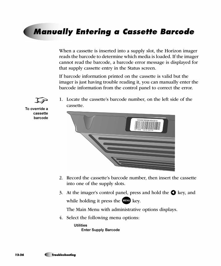
12
When a cassette is inserted into a supply slot, the Horizon imager reads the barcode to determine which media is loaded. If the imager cannot read the barcode, a barcode error message is displayed for that supply cassette entry in the Status screen.
If barcode information printed on the cassette is valid but the imager is just having trouble reading it, you can manually enter the barcode information from the control panel to correct the error.
1. Locate the cassette’s barcode number, on the left side of the cassette.
2. Record the cassette’s barcode number, then insert the cassette into one of the supply slots.
3. At the imager’s control panel, press and hold the key, and
while holding it press the key.
The Main Menu with administrative options displays.
4. Select the following menu options:
Utilities
Enter Supply Barcode
j~åì~ääó=båíÉêáåÖ=~=`~ëëÉííÉ=_~êÅçÇÉ
8To override a
cassette
barcode
�
MENU
-26 Troubleshooting
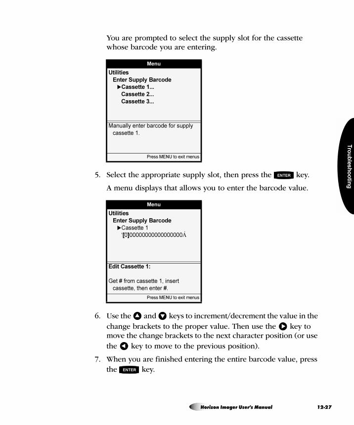
Tro
ub
les
ho
otin
g
You are prompted to select the supply slot for the cassette whose barcode you are entering.
5. Select the appropriate supply slot, then press the key.
A menu displays that allows you to enter the barcode value.
6. Use the and keys to increment/decrement the value in the change brackets to the proper value. Then use the key to move the change brackets to the next character position (or use the key to move to the previous position).
7. When you are finished entering the entire barcode value, press the key.
Menu
Utilities
Enter Supply Barcode
�Cassette 1...
Cassette 2...
Cassette 3...
Manually enter barcode for supply
cassette 1.
Press MENU to exit menus
Menu
Utilities
Enter Supply Barcode
�Cassette 1
‘[0]00000000000000000Á
Edit Cassette 1:
Get # from cassette 1, insert
cassette, then enter #.
Press MENU to exit menus
ENTER
� �
�
�
ENTER
Horizon Imager User’s Manual 12-27
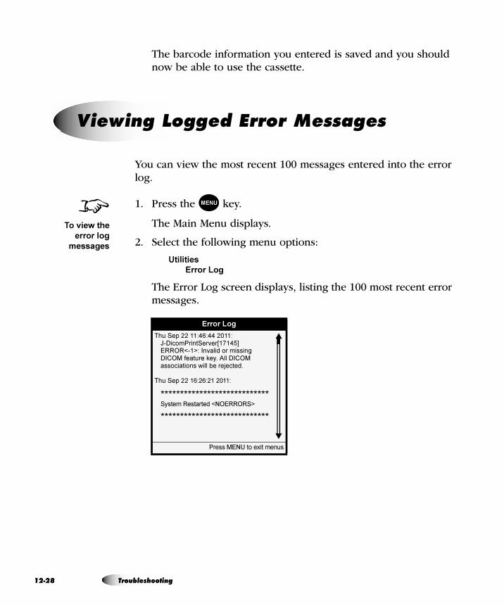
12
The barcode information you entered is saved and you should now be able to use the cassette.
You can view the most recent 100 messages entered into the error log.
1. Press the key.
The Main Menu displays.
2. Select the following menu options:
Utilities
Error Log
The Error Log screen displays, listing the 100 most recent error messages.
sáÉïáåÖ=içÖÖÉÇ=bêêçê=jÉëë~ÖÉë
Error Log
Thu Sep 22 11:46:44 2011:J-DicomPrintServer[17145]ERROR<-1>: Invalid or missing DICOM feature key. All DICOM associations will be rejected.
Thu Sep 22 16:26:21 2011:
****************************System Restarted <NOERRORS>
****************************
Press MENU to exit menus
8To view the
error log
messages
MENU
-28 Troubleshooting
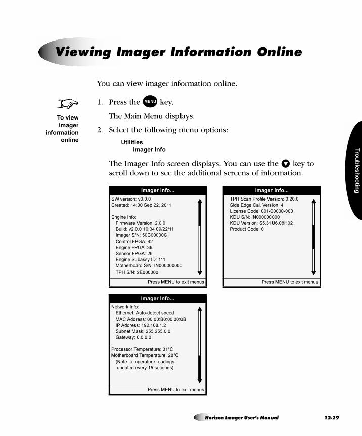
Tro
ub
les
ho
otin
g
You can view imager information online.
1. Press the key.
The Main Menu displays.
2. Select the following menu options:
Utilities
Imager Info
The Imager Info screen displays. You can use the key to scroll down to see the additional screens of information.
sáÉïáåÖ=fã~ÖÉê=fåÑçêã~íáçå=låäáåÉ
8To view
imager
information
online
MENU
�
Imager Info...
SW version: v3.0.0
Created: 14:00 Sep 22, 2011
Engine Info:
Firmware Version: 2.0.0
Build: v2.0.0 10:34 09/22/11
Imager S/N: 50C00000C
Control FPGA: 42
Engine FPGA: 39
Sensor FPGA: 26
Engine Subassy ID: 111
Motherboard S/N: IN000000000
TPH S/N: 2E000000
Press MENU to exit menus
Imager Info...
TPH Scan Profile Version: 3.20.0
Side Edge Cal. Version: 4
License Code: 001-00000-000
KDU S/N: IN000000000
KDU Version: S5.31U6.08H02
Product Code: 0
Press MENU to exit menus
Imager Info...
Network Info:
Ethernet: Auto-detect speed
MAC Address: 00:00:B0:00:00:0B
IP Address: 192.168.1.2
Subnet Mask: 255.255.0.0
Gateway: 0.0.0.0
Processor Temperature: 31°C
Motherboard Temperature: 28°C
(Note: temperature readings
updated every 15 seconds)
Press MENU to exit menus
Horizon Imager User’s Manual 12-29

12
For questions regarding your Horizon Imager, please first refer to this manual, which describes the features and operations. This chapter includes troubleshooting tips for common problems.
If you cannot find the answer to your question in this manual, please visit the Codonics web site at www.codonics.com. The Technical Support area of the web site includes the latest product and troubleshooting information.
If your question was not addressed by the manual or the web site, technical assistance is available by phone at:
Phone: +1 440.243.1198Toll Free: 800.444.1198 (USA only)
Technical support is available anytime.
If you do call for technical support, please have the following information on hand:
• The imager’s serial number (on the back of the imager)
• The imager’s license code (printed on the License Code Certificate which came with the imager, and on the imager’s Smart Card)
• Any control panel status or error messages related to the problem
TIP: Other sources for serial number and license code
You can also find the serial number and license code in the Imager Info menu (refer to
“Viewing Imager Information Online” on page 12-29) and on the Imager Status test print
(refer to “Printing the Imager Status Test Print” on page 2-18).
`çåí~ÅíáåÖ=qÉÅÜåáÅ~ä=pìééçêí
/
-30 Troubleshooting
Tro
ub
les
ho
otin
g
^åçåóãçìë=cqm
When trying to solve a support question, your technical support representative may ask you to upload files to the Codonics anonymous FTP site at
ftp.codonics.com
Valid logins for anonymous FTP are:
anonymous or ftp
For the password, enter your full email address.
File uploads should be placed in the /incoming directory. To avoid confusion on file uploads, please follow these guidelines:
• Check the /incoming directory before uploading your file to make sure a file with the same name as yours has not already been uploaded.
• All sample image print requests and problem report uploads should include an ASCII “readme” file that contains the following information:
- Your company name
- Your company’s full postal mailing address
- Contact person
- Phone number of contact person
- Email of contact person
- For problem reports, a description of problem
- A list of the files being sent
CAUTION All files uploaded using anonymous FTP are readable by other FTP users.
DO NOT upload sensitive or classified information.
Horizon Imager User’s Manual 12-31
12
Also, to save storage space, reduce upload time, and simplify file handling, images and readme files should be archived and compressed into one file:
• From Windows, use the PKZIP (*.zip) archive and compression format.
• From UNIX and Linux, use the tar command to archive the files into one file, then the compress command or an application such as gzip to compress the archive file.
• From a Macintosh, use the StuffIt archive and compression application.
If the images and readme files must be uploaded as separate files, choose a file naming scheme that is consistent. For example:
your_company1.tif
your_company2.tif
your_company.readme
-32 Troubleshooting
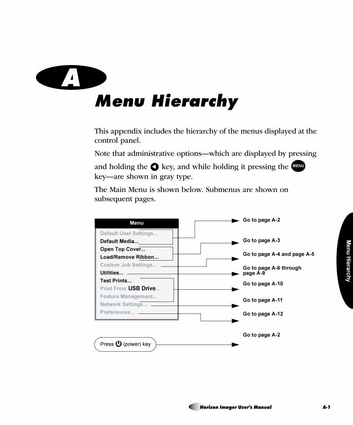
Me
nu
Hie
rarc
hy
= ^jÉåì=eáÉê~êÅÜó
This appendix includes the hierarchy of the menus displayed at the control panel.
Note that administrative options—which are displayed by pressing
and holding the key, and while holding it pressing the key—are shown in gray type.
The Main Menu is shown below. Submenus are shown on subsequent pages.
� MENU
Menu
Default User Settings...
Default Media...
Open Top Cover...
Load/Remove Ribbon...
Custom Job Settings...
Utilities...
Test Prints...
Print From USB Drive...
Feature Management...
Network Settings...
Preferences...
Press (power) key
Go to page A-2
Go to page A-3
Go to page A-4 and page A-5
Go to page A-6 through page A-9
Go to page A-10
Go to page A-11
Go to page A-12
Go to page A-2
Horizon Imager User’s Manual A-1
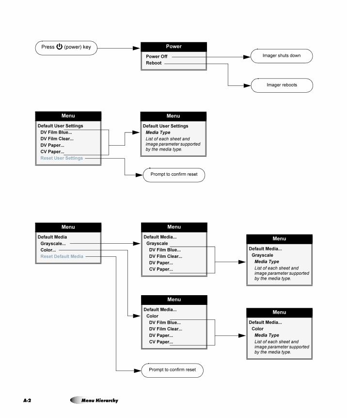
A-2
Menu
Default User Settings
DV Film Blue...
DV Film Clear...
DV Paper...
CV Paper...
Reset User Settings
Power
Power Off
Reboot
Press (power) key
Imager shuts down
Imager reboots
Prompt to confirm reset
Menu
Default Media
Grayscale...
Color...
Reset Default Media
Prompt to confirm reset
Menu
Default Media...
Grayscale
DV Film Blue...
DV Film Clear...
DV Paper...
CV Paper...
Menu
Default User Settings
Media Type
List of each sheet and image parameter supported by the media type.
Menu
Default Media...
Color
DV Film Blue...
DV Film Clear...
DV Paper...
CV Paper...
Menu
Default Media...
Grayscale
Media Type
List of each sheet and image parameter supported by the media type.
Menu
Default Media...
Color
Media Type
List of each sheet and image parameter supported by the media type.
Menu Hierarchy
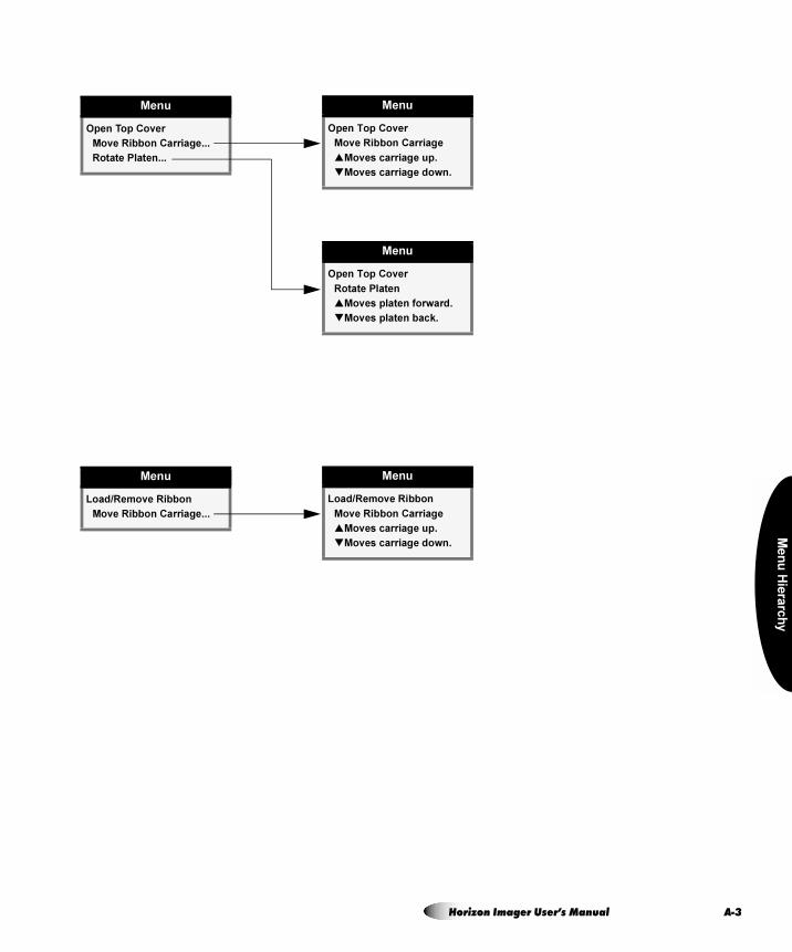
Me
nu
Hie
rarc
hy
Menu
Open Top Cover
Move Ribbon Carriage...
Rotate Platen...
Menu
Open Top Cover
Move Ribbon Carriage
�Moves carriage up.
�Moves carriage down.
Menu
Open Top Cover
Rotate Platen
�Moves platen forward.
�Moves platen back.
Menu
Load/Remove Ribbon
Move Ribbon Carriage...
Menu
Load/Remove Ribbon
Move Ribbon Carriage
�Moves carriage up.
�Moves carriage down.
Horizon Imager User’s Manual A-3
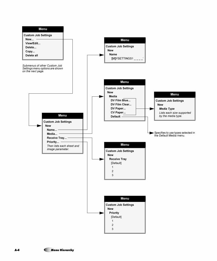
A-4
Menu
Custom Job Settings
New
Name...
Media...
Receive Tray...
Priority...
Then lists each sheet and image parameter.
Menu
Custom Job Settings
New
Media Type
Lists each size supported by the media type.
Menu
Custom Job Settings
New
Name
‘[M]YSETTINGS1 _ _ _ _’
Menu
Custom Job Settings
New
Media
DV Film Blue...
DV Film Clear...
DV Paper...
CV Paper...
Default
Menu
Custom Job Settings
New
Receive Tray
[Default]
1
2
3
Menu
Custom Job Settings
New
Priority
[Default]
1
2
3
Menu
Custom Job Settings
New...
View/Edit...
Delete...
Copy...
Delete all
Submenus of other Custom Job Settings menu options are shown on the next page.
Specifies to use types selected in the Default Media menu.
Menu Hierarchy
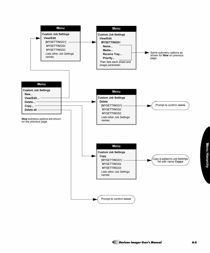
Me
nu
Hie
rarc
hy
Menu
Custom Job Settings
View/Edit
[MYSETTINGS1]
MYSETTINGS2
MYSETTINGS3
Lists other Job Settings names.
Menu
Custom Job Settings
View/Edit
MYSETTINGS1
Name...
Media...
Receive Tray...
Priority...
Then lists each sheet and image parameter.
Menu
Custom Job Settings
New...
View/Edit...
Delete...
Copy...
Delete all
New submenu options are shown on the previous page.
Same submenu options as shown for New on previous page.
Menu
Custom Job Settings
Delete
[MYSETTINGS1]
MYSETTINGS2
MYSETTINGS3
Lists other Job Settings names.
Prompt to confirm delete
Menu
Custom Job Settings
Copy
[MYSETTINGS1]
MYSETTINGS2
MYSETTINGS3
Lists other Job Settings names.
Copy is added to Job Settings list with name Copyx
Prompt to confirm delete
Horizon Imager User’s Manual A-5
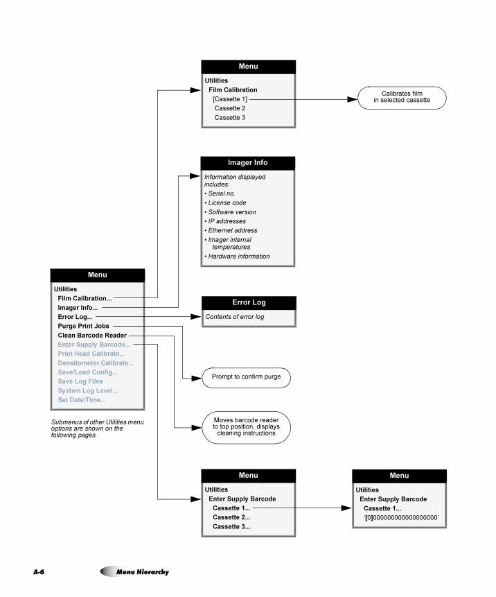
A-6
Menu
Utilities
Film Calibration...
Imager Info...
Error Log...
Purge Print Jobs
Clean Barcode Reader
Enter Supply Barcode...
Print Head Calibrate...
Densitometer Calibrate...
Save/Load Config...
Save Log Files
System Log Level...
Set Date/Time...
Moves barcode readerto top position, displays
cleaning instructions
Error Log
Contents of error log
Imager Info
Information displayed includes:
• Serial no.
• License code
• Software version
• IP addresses
• Ethernet address
• Imager internal temperatures
• Hardware information
Menu
Utilities
Enter Supply Barcode
Cassette 1...
‘[0]000000000000000000’
Menu
Utilities
Film Calibration
[Cassette 1]
Cassette 2
Cassette 3
Menu
Utilities
Enter Supply Barcode
Cassette 1...
Cassette 2...
Cassette 3...
Prompt to confirm purge
Calibrates filmin selected cassette
Submenus of other Utilities menu options are shown on the following pages.
Menu Hierarchy
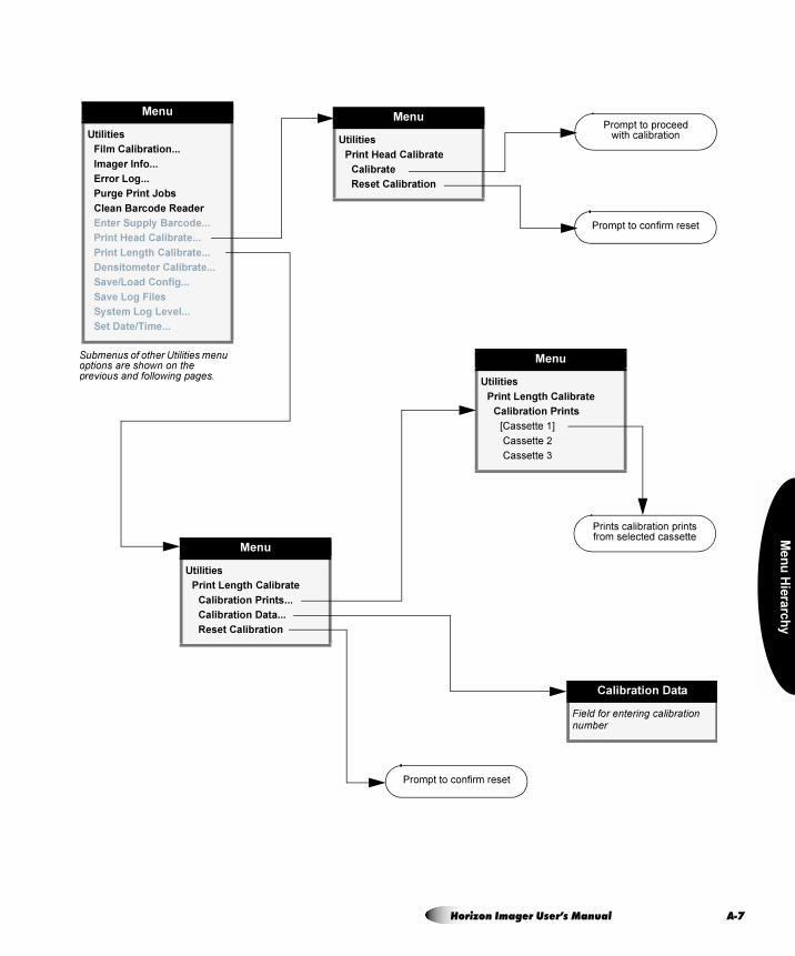
Me
nu
Hie
rarc
hy
Menu
Utilities
Film Calibration...
Imager Info...
Error Log...
Purge Print Jobs
Clean Barcode Reader
Enter Supply Barcode...
Print Head Calibrate...
Print Length Calibrate...
Densitometer Calibrate...
Save/Load Config...
Save Log Files
System Log Level...
Set Date/Time...
Prompt to proceedwith calibration
Menu
Utilities
Print Length Calibrate
Calibration Prints...
Calibration Data...
Reset Calibration
Calibration Data
Field for entering calibration number
Prompt to confirm reset
Menu
Utilities
Print Length Calibrate
Calibration Prints
[Cassette 1]
Cassette 2
Cassette 3
Prints calibration printsfrom selected cassette
Submenus of other Utilities menu options are shown on the previous and following pages.
Menu
Utilities
Print Head Calibrate
Calibrate
Reset Calibration
Prompt to confirm reset
Horizon Imager User’s Manual A-7
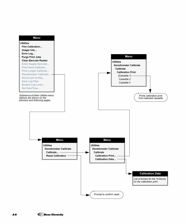
A-8 Menu Hierarchy
Menu
Utilities
Film Calibration...
Imager Info...
Error Log...
Purge Print Jobs
Clean Barcode Reader
Enter Supply Barcode...
Print Head Calibrate...
Print Length Calibrate...
Densitometer Calibrate...
Save/Load Config...
Save Log Files
System Log Level...
Set Date/Time...
Menu
Utilities
Densitometer Calibrate
Calibrate...
Reset Calibration
Menu
Utilities
Densitometer Calibrate
Calibrate
Calibration Print...
Calibration Data...
Calibration Data
List of entries for the 16 blocks on the calibration print.
Prompt to confirm reset
Menu
Utilities
Densitometer Calibrate
Calibrate
Calibration Print
[Cassette 1]
Cassette 2
Cassette 3
Prints calibration printfrom selected cassette
Submenus of other Utilities menu options are shown on the previous and following pages.
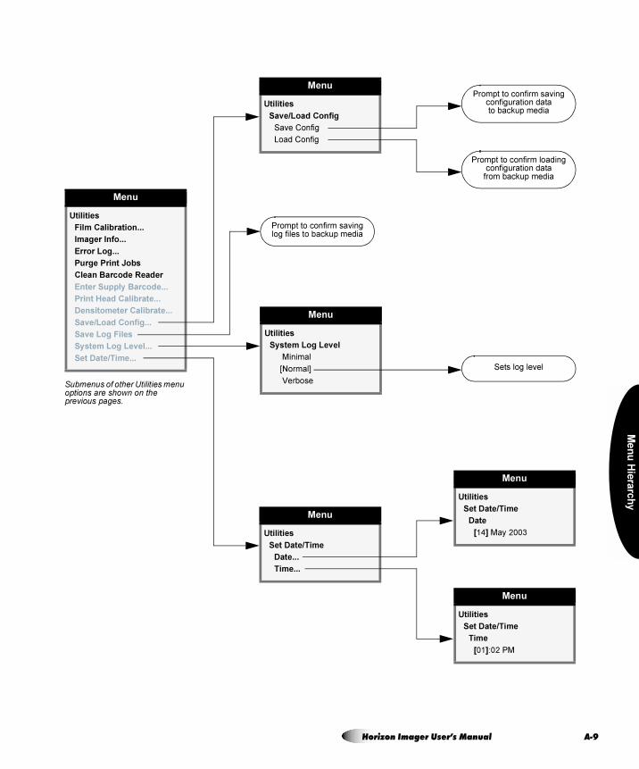
Me
nu
Hie
rarc
hy
Menu
Utilities
Film Calibration...
Imager Info...
Error Log...
Purge Print Jobs
Clean Barcode Reader
Enter Supply Barcode...
Print Head Calibrate...
Densitometer Calibrate...
Save/Load Config...
Save Log Files
System Log Level...
Set Date/Time...
Prompt to confirm savinglog files to backup media
Menu
Utilities
Set Date/Time
Date
[14] May 2003
Menu
Utilities
Save/Load Config
Save Config
Load Config
Menu
Utilities
Set Date/Time
Date...
Time...
Menu
Utilities
System Log Level
Minimal
[Normal]
Verbose
Prompt to confirm loadingconfiguration data
from backup media
Prompt to confirm savingconfiguration datato backup media
Sets log level
Menu
Utilities
Set Date/Time
Time
[01]:02 PM
Submenus of other Utilities menu options are shown on the previous pages.
Horizon Imager User’s Manual A-9
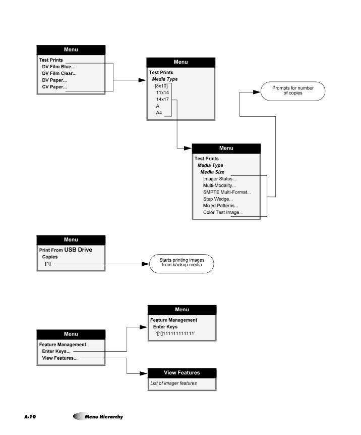
A-1
Menu
Test Prints
DV Film Blue...
DV Film Clear...
DV Paper...
CV Paper...
Menu
Test Prints
Media Type
[8x10]
11x14
14x17
A
A4
Menu
Test Prints
Media Type
Media Size
Imager Status...
Multi-Modality...
SMPTE Multi-Format...
Step Wedge...
Mixed Patterns...
Color Test Image...
Prompts for numberof copies
Menu
Print From USB DriveCopies
[1]Starts printing images
from backup media
Menu
Feature Management
Enter Keys...
View Features...
Menu
Feature Management
Enter Keys
‘[1]111111111111’
View Features
List of imager features
0 Menu Hierarchy
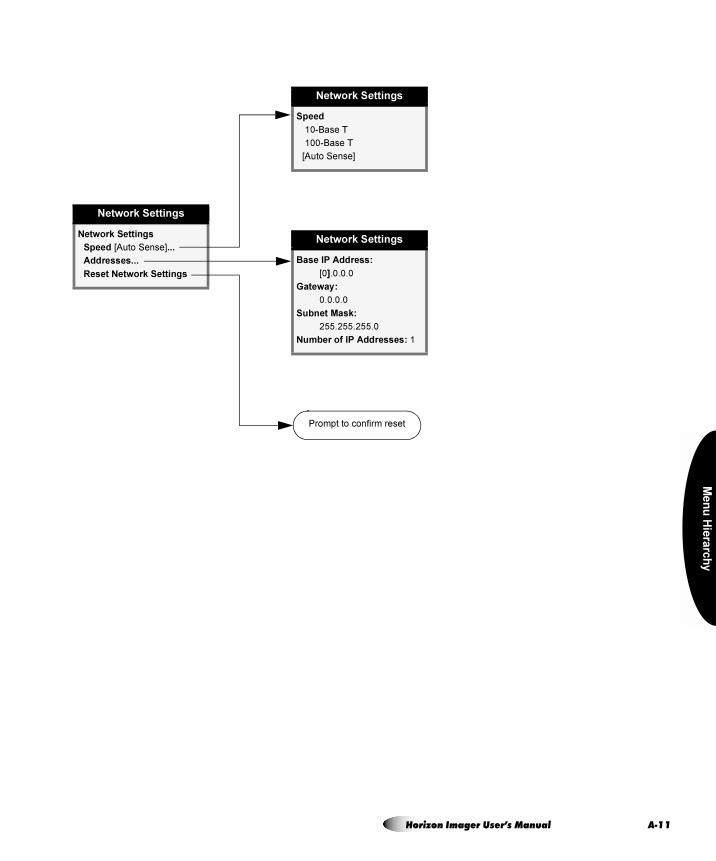
Me
nu
Hie
rarc
hy
Network Settings
Network Settings
Speed [Auto Sense]...
Addresses...
Reset Network Settings
Network Settings
Base IP Address:
[0].0.0.0
Gateway:
0.0.0.0
Subnet Mask:
255.255.255.0
Number of IP Addresses: 1
Network Settings
Speed
10-Base T
100-Base T
[Auto Sense]
Prompt to confirm reset
Horizon Imager User’s Manual A-11
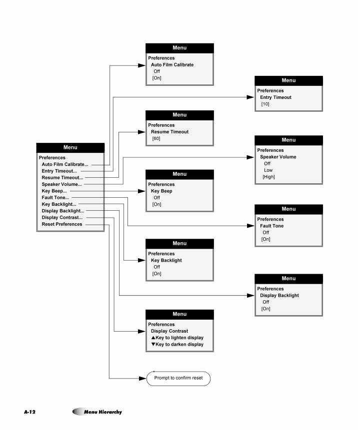
A-1
Menu
Preferences
Auto Film Calibrate...
Entry Timeout...
Resume Timeout...
Speaker Volume...
Key Beep...
Fault Tone...
Key Backlight...
Display Backlight...
Display Contrast...
Reset Preferences
Prompt to confirm reset
Menu
Preferences
Auto Film Calibrate
Off
[On]Menu
Preferences
Entry Timeout
[10]
Menu
Preferences
Resume Timeout
[60] Menu
Preferences
Speaker Volume
Off
Low
[High]Menu
Preferences
Key Beep
Off
[On]
Menu
Preferences
Key Backlight
Off
[On]
Menu
Preferences
Fault Tone
Off
[On]
Menu
Preferences
Display Backlight
Off
[On]
Menu
Preferences
Display Contrast
�Key to lighten display
�Key to darken display
2 Menu Hierarchy
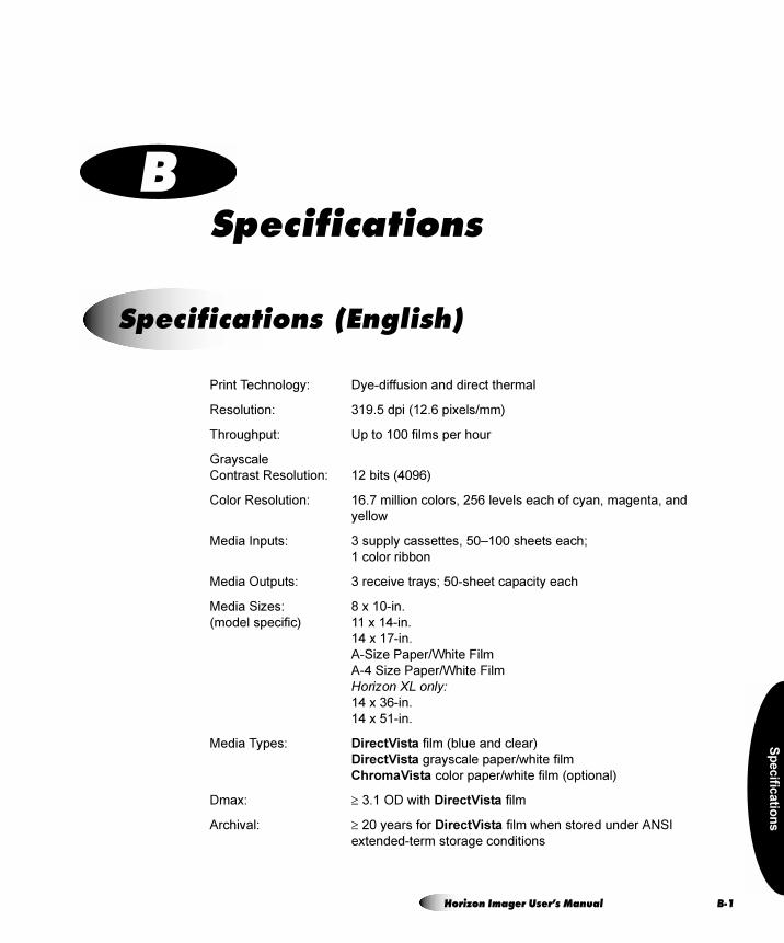
Sp
ecific
atio
ns
= _péÉÅáÑáÅ~íáçåë
Print Technology: Dye-diffusion and direct thermal
Resolution: 319.5 dpi (12.6 pixels/mm)
Throughput: Up to 100 films per hour
Grayscale
Contrast Resolution: 12 bits (4096)
Color Resolution: 16.7 million colors, 256 levels each of cyan, magenta, and
yellow
Media Inputs: 3 supply cassettes, 50–100 sheets each;
1 color ribbon
Media Outputs: 3 receive trays; 50-sheet capacity each
Media Sizes: 8 x 10-in.
(model specific) 11 x 14-in.
14 x 17-in.
A-Size Paper/White Film
A-4 Size Paper/White Film
Horizon XL only:14 x 36-in.
14 x 51-in.
Media Types: DirectVista film (blue and clear)
DirectVista grayscale paper/white film
ChromaVista color paper/white film (optional)
Dmax: ≥ 3.1 OD with DirectVista film
Archival: ≥ 20 years for DirectVista film when stored under ANSI
extended-term storage conditions
péÉÅáÑáÅ~íáçåë=EbåÖäáëÜF
Horizon Imager User’s Manual B-1
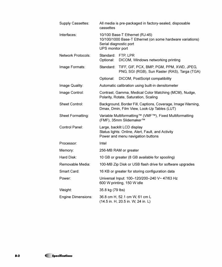
B-2
Supply Cassettes: All media is pre-packaged in factory-sealed, disposable
cassettes
Interfaces: 10/100 Base-T Ethernet (RJ-45)
10/100/1000 Base-T Ethernet (on some hardware variations)
Serial diagnostic port
UPS monitor port
Network Protocols: Standard: FTP, LPR
Optional: DICOM, Windows networking printing
Image Formats: Standard: TIFF, GIF, PCX, BMP, PGM, PPM, XWD, JPEG,
PNG, SGI (RGB), Sun Raster (RAS), Targa (TGA)
Optional: DICOM, PostScript compatibility
Image Quality: Automatic calibration using built-in densitometer
Image Control: Contrast, Gamma, Medical Color Matching (MCM), Nudge,
Polarity, Rotate, Saturation, Scaling
Sheet Control: Background, Border Fill, Captions, Coverage, Image Warning,
Dmax, Dmin, Film View, Look-Up Tables (LUT)
Sheet Formatting: Variable Multiformatting™ (VMF™), Fixed Multiformatting
(FMF), 35mm Slidemaker™
Control Panel: Large, backlit LCD display
Status lights: Online, Alert, Fault, and Activity
Power and menu navigation buttons
Processor: Intel
Memory: 256-MB RAM or greater
Hard Disk: 10 GB or greater (8 GB available for spooling)
Removable Media: 100-MB Zip Disk or USB flash drive for software upgrades
Smart Card: 16 KB or greater for storing configuration data
Power: Universal Input: 100–120/200–240 V~ 47/63 Hz
600 W printing, 150 W idle
Weight: 35.8 kg (79 lbs)
Engine Dimensions: 36.8 cm H, 52.1 cm W, 61 cm L
(14.5 in. H, 20.5 in. W, 24 in. L)
Specifications
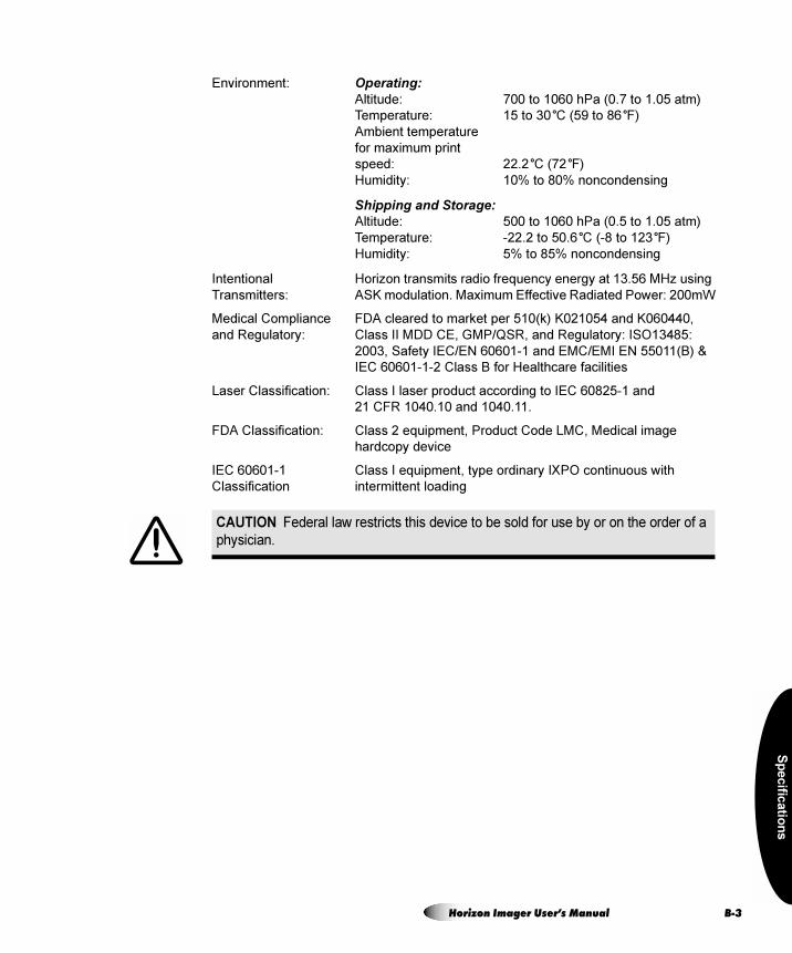
Sp
ecific
atio
ns
Environment: Operating:
Altitude: 700 to 1060 hPa (0.7 to 1.05 atm)
Temperature: 15 to 30°C (59 to 86°F)
Ambient temperature
for maximum print
speed: 22.2°C (72°F)
Humidity: 10% to 80% noncondensing
Shipping and Storage:
Altitude: 500 to 1060 hPa (0.5 to 1.05 atm)
Temperature: -22.2 to 50.6°C (-8 to 123°F)
Humidity: 5% to 85% noncondensing
Intentional Horizon transmits radio frequency energy at 13.56 MHz using
Transmitters: ASK modulation. Maximum Effective Radiated Power: 200mW
Medical Compliance FDA cleared to market per 510(k) K021054 and K060440,
and Regulatory: Class II MDD CE, GMP/QSR, and Regulatory: ISO13485:
2003, Safety IEC/EN 60601-1 and EMC/EMI EN 55011(B) &
IEC 60601-1-2 Class B for Healthcare facilities
Laser Classification: Class I laser product according to IEC 60825-1 and
21 CFR 1040.10 and 1040.11.
FDA Classification: Class 2 equipment, Product Code LMC, Medical image
hardcopy device
IEC 60601-1 Class I equipment, type ordinary IXPO continuous with
Classification intermittent loading
CAUTION Federal law restricts this device to be sold for use by or on the order of a
physician.
Horizon Imager User’s Manual B-3
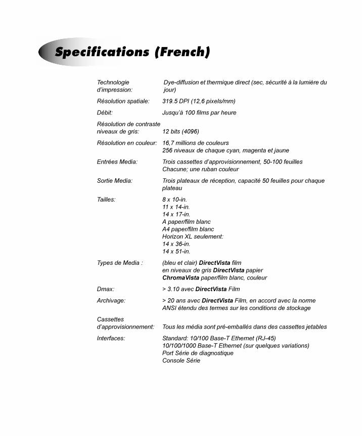
Technologie Dye-diffusion et thermique direct (sec, sécurité à la lumière dud’impression: jour)
Résolution spatiale: 319.5 DPI (12,6 pixels/mm)
Débit: Jusqu’à 100 films par heure
Résolution de contrasteniveaux de gris: 12 bits (4096)
Résolution en couleur: 16,7 millions de couleurs256 niveaux de chaque cyan, magenta et jaune
Entrées Media: Trois cassettes d’approvisionnement, 50-100 feuilles Chacune; une ruban couleur
Sortie Media: Trois plateaux de réception, capacité 50 feuilles pour chaque plateau
Tailles: 8 x 10-in. 11 x 14-in.14 x 17-in. A paper/film blancA4 paper/film blancHorizon XL seulement: 14 x 36-in.14 x 51-in.
Types de Media : (bleu et clair) DirectVista filmen niveaux de gris DirectVista papierChromaVista paper/film blanc, couleur
Dmax: > 3.10 avec DirectVista Film
Archivage: > 20 ans avec DirectVista Film, en accord avec la norme ANSI étendu des termes sur les conditions de stockage
Cassettes d’approvisionnement: Tous les média sont pré-emballés dans des cassettes jetables
Interfaces: Standard: 10/100 Base-T Ethernet (RJ-45)10/100/1000 Base-T Ethernet (sur quelques variations)Port Série de diagnostiqueConsole Série
péÉÅáÑáÅ~íáçåë=EcêÉåÅÜF
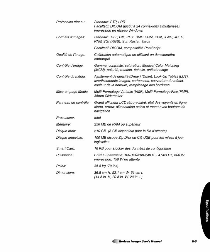
Sp
ecific
atio
ns
Protocoles réseau: Standard: FTP, LPRFacultatif: DICOM (jusqu’à 24 connexions simultanées), impression en réseau Windows
Formats d’images: Standard: TIFF, GIF, PCX, BMP, PGM, PPM, XWD, JPEG, PNG, SGI (RGB), Sun Raster, Targa
Facultatif: DICOM, compatibilité PostScript
Qualité de l’image: Calibration automatique en utilisant un densitomètre embarqué
Contrôle d’image: Gamma, contraste, saturation, Medical Color Matching (MCM), polarité, rotation, échelle, anticrénelage
Contrôle du média: Ajustement de densité (Dmax) (Dmin), Look-Up Tables (LUT), avertissements images, cartouches, couverture du média, couleur de la bordure, remplissage des bordures
Mise en page Media: Multi-Formatage Variable (VMF), Multi-Formatage Fixe (FMF), 35mm Slidemaker
Panneau de contrôle: Grand afficheur LCD rétro-éclairé, état des voyants en ligne, alerte, erreur, alimentation active et menu avec boutons de navigation
Processeur: Intel
Mémoire: 256 MB de RAM ou supérieur
Disque durs: >10 GB (8 GB disponible pour la file d’attente)
Disque amovible: 100 MB disque Zip Disk ou Clé USB pour les mises à jour logicielles
Smart Card: 16 KB pour stocker des données de configuration
Puissance: Entrée universelle: 100-120/200-240 V ~ 47/63 Hz, 600 W impression, 150 W en attente
Poids: 35.8 kg (79 lbs).
Dimensions: 36.8 cm H, 52.1 cm W, 61 cm L(14.5 in. H, 20.5 in. W, 24 in. L)
Horizon Imager User’s Manual B-5
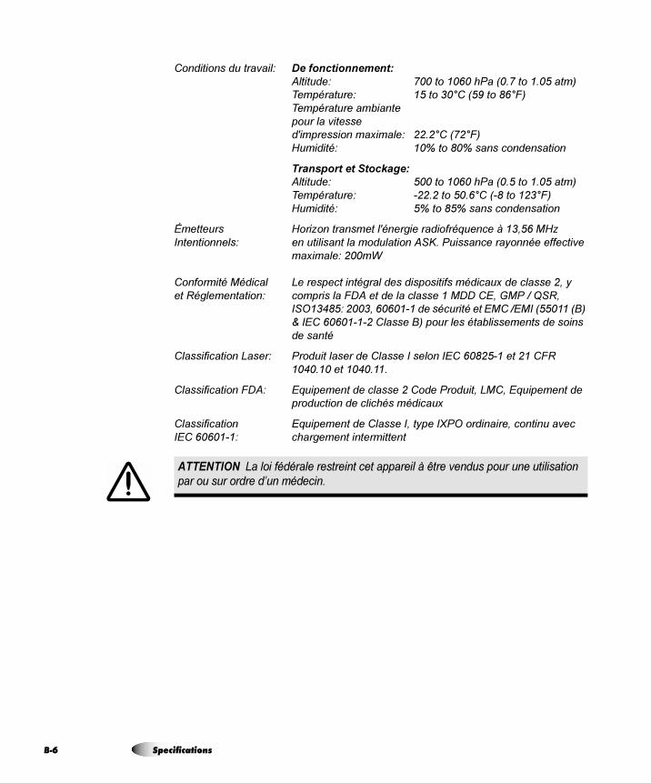
B-6
Conditions du travail: De fonctionnement:
Altitude: 700 to 1060 hPa (0.7 to 1.05 atm)Température: 15 to 30°C (59 to 86°F)Température ambiantepour la vitessed'impression maximale: 22.2°C (72°F)Humidité: 10% to 80% sans condensation
Transport et Stockage:
Altitude: 500 to 1060 hPa (0.5 to 1.05 atm)Température: -22.2 to 50.6°C (-8 to 123°F)Humidité: 5% to 85% sans condensation
Émetteurs Horizon transmet l'énergie radiofréquence à 13,56 MHzIntentionnels: en utilisant la modulation ASK. Puissance rayonnée effective
maximale: 200mW
Conformité Médical Le respect intégral des dispositifs médicaux de classe 2, yet Réglementation: compris la FDA et de la classe 1 MDD CE, GMP / QSR,
ISO13485: 2003, 60601-1 de sécurité et EMC /EMI (55011 (B) & IEC 60601-1-2 Classe B) pour les établissements de soins de santé
Classification Laser: Produit laser de Classe I selon IEC 60825-1 et 21 CFR 1040.10 et 1040.11.
Classification FDA: Equipement de classe 2 Code Produit, LMC, Equipement de production de clichés médicaux
Classification Equipement de Classe I, type IXPO ordinaire, continu avecIEC 60601-1: chargement intermittent
ATTENTION La loi fédérale restreint cet appareil à être vendus pour une utilisation
par ou sur ordre d’un médecin.
Specifications
Sys
tem
Jo
b S
ettin
gs F
iles
= `póëíÉã=gçÄ=pÉííáåÖë=cáäÉë
The table on the following pages lists the system Job Settings files that come with the Horizon imager. Note that there is a system Job Settings file for each supported media type and size combination. As such, they contain only the Media Type and Media Size parameters.
The DefaultGrayscale and DefaultColor system Job Settings files contain no sheet or image parameters and, if used, cause the imager to default to the Default User Settings for Grayscale and Color, set at the control panel.
Horizon Imager User’s Manual C-1
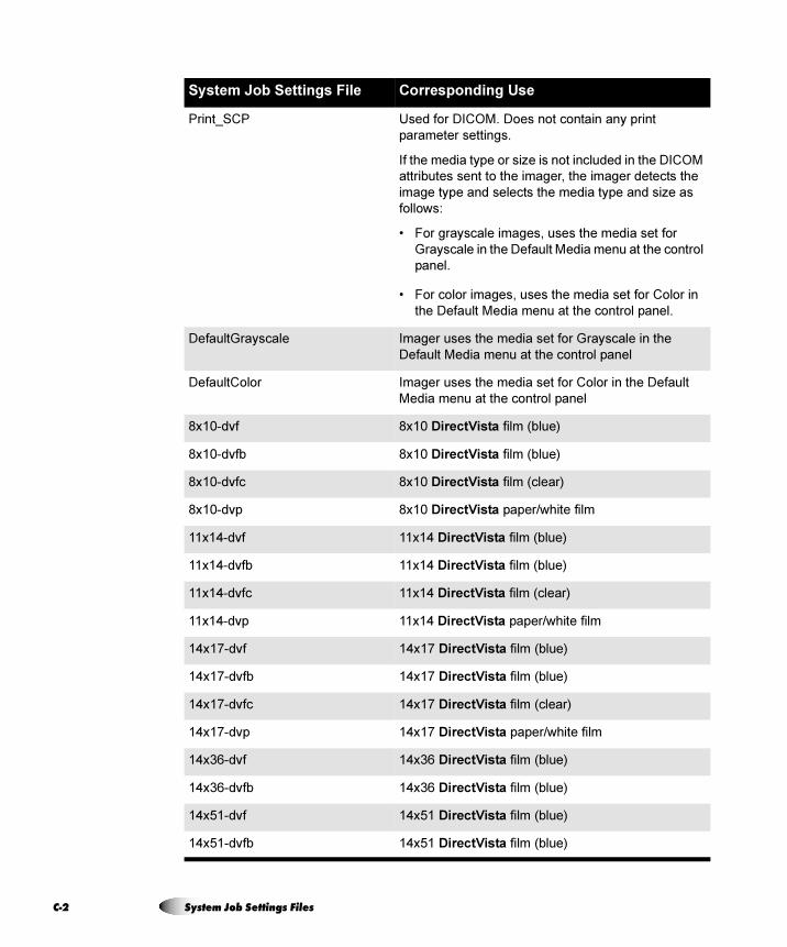
C-2
System Job Settings File Corresponding Use
Print_SCP Used for DICOM. Does not contain any print
parameter settings.
If the media type or size is not included in the DICOM
attributes sent to the imager, the imager detects the
image type and selects the media type and size as
follows:
• For grayscale images, uses the media set for
Grayscale in the Default Media menu at the control
panel.
• For color images, uses the media set for Color in
the Default Media menu at the control panel.
DefaultGrayscale Imager uses the media set for Grayscale in the
Default Media menu at the control panel
DefaultColor Imager uses the media set for Color in the Default
Media menu at the control panel
8x10-dvf 8x10 DirectVista film (blue)
8x10-dvfb 8x10 DirectVista film (blue)
8x10-dvfc 8x10 DirectVista film (clear)
8x10-dvp 8x10 DirectVista paper/white film
11x14-dvf 11x14 DirectVista film (blue)
11x14-dvfb 11x14 DirectVista film (blue)
11x14-dvfc 11x14 DirectVista film (clear)
11x14-dvp 11x14 DirectVista paper/white film
14x17-dvf 14x17 DirectVista film (blue)
14x17-dvfb 14x17 DirectVista film (blue)
14x17-dvfc 14x17 DirectVista film (clear)
14x17-dvp 14x17 DirectVista paper/white film
14x36-dvf 14x36 DirectVista film (blue)
14x36-dvfb 14x36 DirectVista film (blue)
14x51-dvf 14x51 DirectVista film (blue)
14x51-dvfb 14x51 DirectVista film (blue)
System Job Settings Files
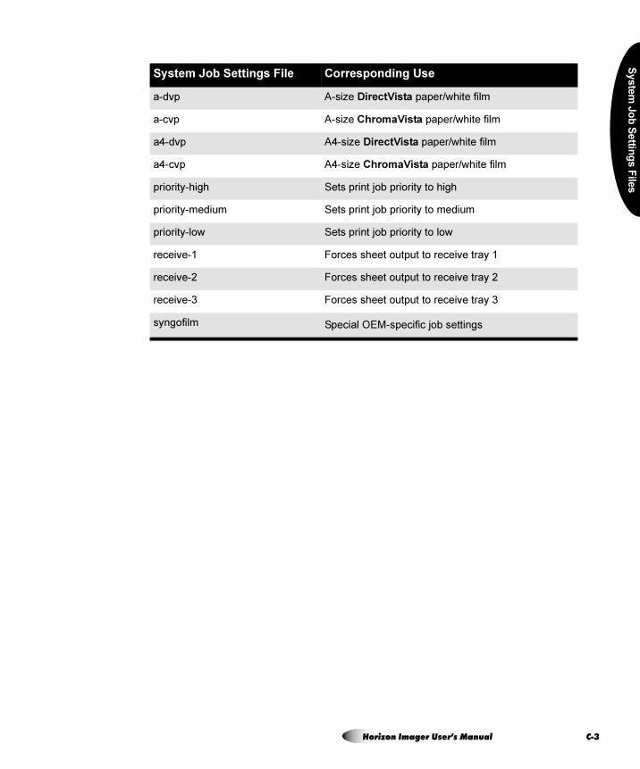
Sys
tem
Jo
b S
ettin
gs F
iles
a-dvp A-size DirectVista paper/white film
a-cvp A-size ChromaVista paper/white film
a4-dvp A4-size DirectVista paper/white film
a4-cvp A4-size ChromaVista paper/white film
priority-high Sets print job priority to high
priority-medium Sets print job priority to medium
priority-low Sets print job priority to low
receive-1 Forces sheet output to receive tray 1
receive-2 Forces sheet output to receive tray 2
receive-3 Forces sheet output to receive tray 3
syngofilm Special OEM-specific job settings
System Job Settings File Corresponding Use
Horizon Imager User’s Manual C-3

Prin
t Jo
b P
ara
me
ters
= amêáåí=gçÄ=m~ê~ãÉíÉêë
The tables on the following pages provide summaries of the print job parameters that can be changed using the Default Media, Default User Settings, and Custom Job Settings menus at the control panel; Job Settings files; and backup media settings.txt files.
The tables are broken down by job-, sheet-, and image-related parameters.
NOTE: Border Fill, Coverage, LUT, and Rotate are considered advanced parameters and
should be changed only by a key operator.
For a complete explanation of the print job parameters, refer to the Horizon Imager Technical Manual.
3
Horizon Imager User’s Manual D-1
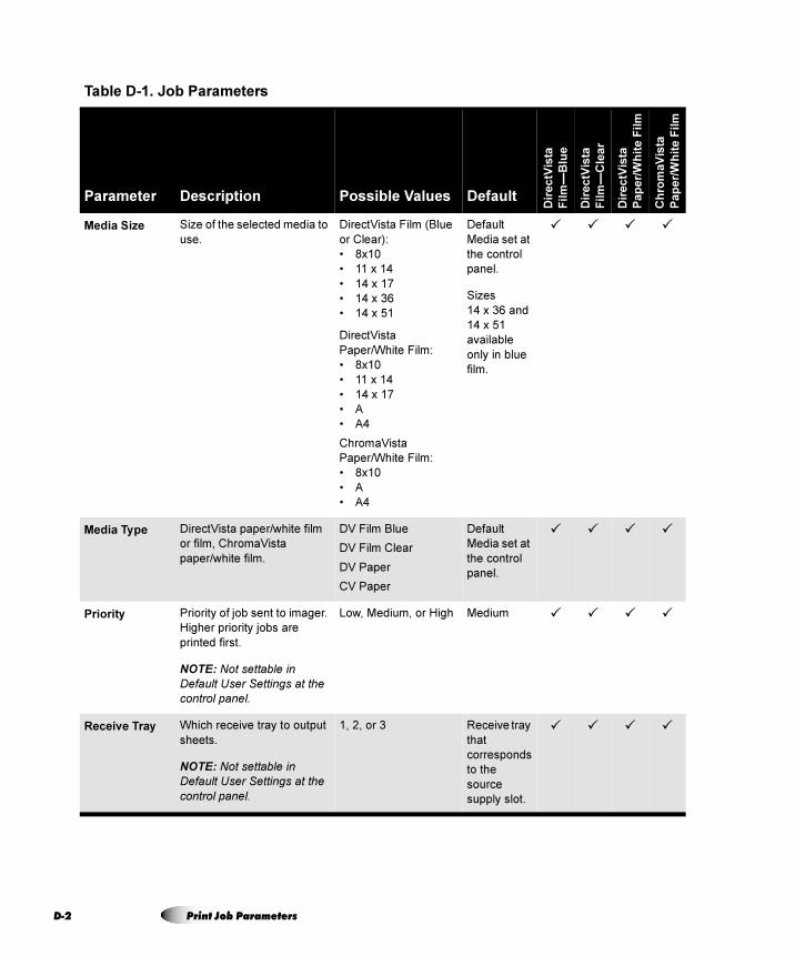
D-2
Table D-1. Job Parameters
Parameter Description Possible Values Default
Dir
ec
tVis
ta
Fil
m—
Blu
e
Dir
ec
tVis
ta
Fil
m—
Cle
ar
Dir
ec
tVis
ta
Pa
pe
r/W
hit
e F
ilm
Ch
rom
aV
ista
Pa
pe
r/W
hit
e F
ilm
Media Size Size of the selected media to
use.
DirectVista Film (Blue
or Clear):
• 8x10
• 11 x 14
• 14 x 17
• 14 x 36
• 14 x 51
DirectVista
Paper/White Film:
• 8x10
• 11 x 14
• 14 x 17
• A
• A4
ChromaVista
Paper/White Film:
• 8x10
• A
• A4
Default
Media set at
the control
panel.
Sizes
14 x 36 and
14 x 51
available
only in blue
film.
� � � �
Media Type DirectVista paper/white film
or film, ChromaVista
paper/white film.
DV Film Blue
DV Film Clear
DV Paper
CV Paper
Default
Media set at
the control
panel.
� � � �
Priority Priority of job sent to imager.
Higher priority jobs are
printed first.
NOTE: Not settable in
Default User Settings at the
control panel.
Low, Medium, or High Medium � � � �
Receive Tray Which receive tray to output
sheets.
NOTE: Not settable in
Default User Settings at the
control panel.
1, 2, or 3 Receive tray
that
corresponds
to the
source
supply slot.
� � � �
Print Job Parameters
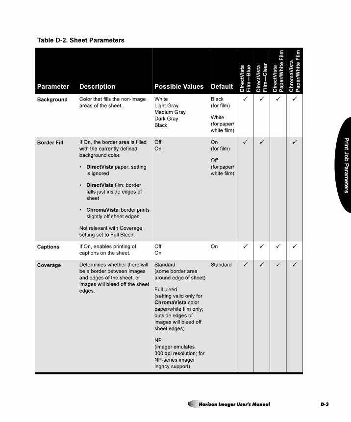
Prin
t Jo
b P
ara
me
ters
Table D-2. Sheet Parameters
Parameter Description Possible Values Default
Dir
ec
tVis
ta
Fil
m—
Blu
e
Dir
ec
tVis
ta
Fil
m—
Cle
ar
Dir
ec
tVis
ta
Pa
pe
r/W
hit
e F
ilm
Ch
rom
aV
ista
Pa
pe
r/W
hit
e F
ilm
Background Color that fills the non-image
areas of the sheet.
White
Light Gray
Medium Gray
Dark Gray
Black
Black
(for film)
White
(for paper/
white film)
� � � �
Border Fill If On, the border area is filled
with the currently defined
background color.
• DirectVista paper: setting
is ignored
• DirectVista film: border
falls just inside edges of
sheet
• ChromaVista: border prints
slightly off sheet edges
Not relevant with Coverage
setting set to Full Bleed.
Off
On
On
(for film)
Off
(for paper/
white film)
� � �
Captions If On, enables printing of
captions on the sheet.
Off
On
On � � � �
Coverage Determines whether there will
be a border between images
and edges of the sheet, or
images will bleed off the sheet
edges.
Standard
(some border area
around edge of sheet)
Full bleed
(setting valid only for
ChromaVista color
paper/white film only;
outside edges of
images will bleed off
sheet edges)
NP
(imager emulates
300 dpi resolution; for
NP-series imager
legacy support)
Standard � � � �
Horizon Imager User’s Manual D-3
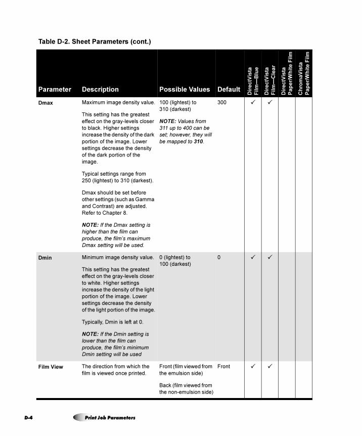
D-4
Dmax Maximum image density value.
This setting has the greatest
effect on the gray-levels closer
to black. Higher settings
increase the density of the dark
portion of the image. Lower
settings decrease the density
of the dark portion of the
image.
Typical settings range from
250 (lightest) to 310 (darkest).
Dmax should be set before
other settings (such as Gamma
and Contrast) are adjusted.
Refer to Chapter 8.
NOTE: If the Dmax setting is
higher than the film can
produce, the film’s maximum
Dmax setting will be used.
100 (lightest) to
310 (darkest)
NOTE: Values from
311 up to 400 can be
set; however, they will
be mapped to 310.
300 � �
Dmin Minimum image density value.
This setting has the greatest
effect on the gray-levels closer
to white. Higher settings
increase the density of the light
portion of the image. Lower
settings decrease the density
of the light portion of the image.
Typically, Dmin is left at 0.
NOTE: If the Dmin setting is
lower than the film can
produce, the film’s minimum
Dmin setting will be used
0 (lightest) to
100 (darkest)
0 � �
Film View The direction from which the
film is viewed once printed.
Front (film viewed from
the emulsion side)
Back (film viewed from
the non-emulsion side)
Front � �
Table D-2. Sheet Parameters (cont.)
Parameter Description Possible Values Default
Dir
ec
tVis
ta
Fil
m—
Blu
e
Dir
ec
tVis
ta
Fil
m—
Cle
ar
Dir
ec
tVis
ta
Pa
pe
r/W
hit
e F
ilm
Ch
rom
aV
ista
Pa
pe
r/W
hit
e F
ilm
Print Job Parameters
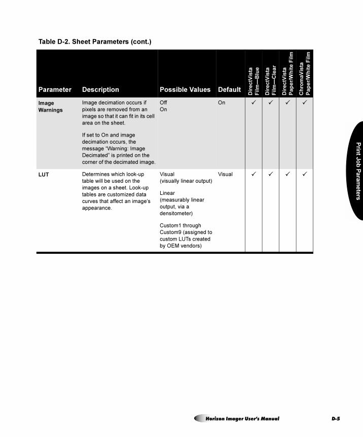
Prin
t Jo
b P
ara
me
ters
Image
Warnings
Image decimation occurs if
pixels are removed from an
image so that it can fit in its cell
area on the sheet.
If set to On and image
decimation occurs, the
message “Warning: Image
Decimated” is printed on the
corner of the decimated image.
Off
On
On � � � �
LUT Determines which look-up
table will be used on the
images on a sheet. Look-up
tables are customized data
curves that affect an image’s
appearance.
Visual
(visually linear output)
Linear
(measurably linear
output, via a
densitometer)
Custom1 through
Custom9 (assigned to
custom LUTs created
by OEM vendors)
Visual � � � �
Table D-2. Sheet Parameters (cont.)
Parameter Description Possible Values Default
Dir
ec
tVis
ta
Fil
m—
Blu
e
Dir
ec
tVis
ta
Fil
m—
Cle
ar
Dir
ec
tVis
ta
Pa
pe
r/W
hit
e F
ilm
Ch
rom
aV
ista
Pa
pe
r/W
hit
e F
ilm
Horizon Imager User’s Manual D-5
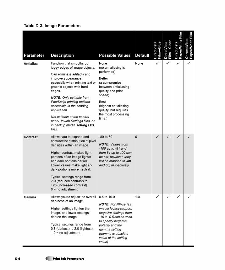
D-6
Table D-3. Image Parameters
Parameter Description Possible Values Default
Dir
ec
tVis
ta
Fil
m—
Blu
e
Dir
ec
tVis
ta
Fil
m—
Cle
ar
Dir
ec
tVis
ta
Pa
pe
r/W
hit
e F
ilm
Ch
rom
aV
ista
Pa
pe
r/W
hit
e F
ilm
Antialias Function that smooths out
jaggy edges of image objects.
Can eliminate artifacts and
improve appearance,
especially when printing text or
graphic objects with hard
edges.
NOTE: Only settable from
PostScript printing options,
accessible in the sending
application.
Not settable at the control
panel, in Job Settings files, or
in backup media settings.txt
files.
None
(no antialiasing is
performed)
Better
(a compromise
between antialiasing
quality and print
speed)
Best
(highest antialiasing
quality, but requires
the most processing
time.)
None � � � �
Contrast Allows you to expand and
contract the distribution of pixel
densities within an image.
Higher contrast makes light
portions of an image lighter
and dark portions darker.
Lower values make light and
dark portions more neutral.
Typical settings range from
-10 (reduced contrast) to
+25 (increased contrast).
0 = no adjustment.
-80 to 80
NOTE: Values from
-100 up to -81 and
from 81 up to 100 can
be set; however, they
will be mapped to -80
and 80, respectively.
0 � � � �
Gamma Allows you to adjust the overall
darkness of an image.
Higher settings lighten the
image, and lower settings
darken the image.
Typical settings range from
0.8 (darkest) to 2.0 (lightest).
1.0 = no adjustment.
0.5 to 10.0
NOTE: For NP-series
imager legacy support,
negative settings from
-10 to -0.5 can be used
to specify negative
polarity and the
gamma setting
(gamma is absolute
value of the setting
value).
1.0 � � � �
Print Job Parameters
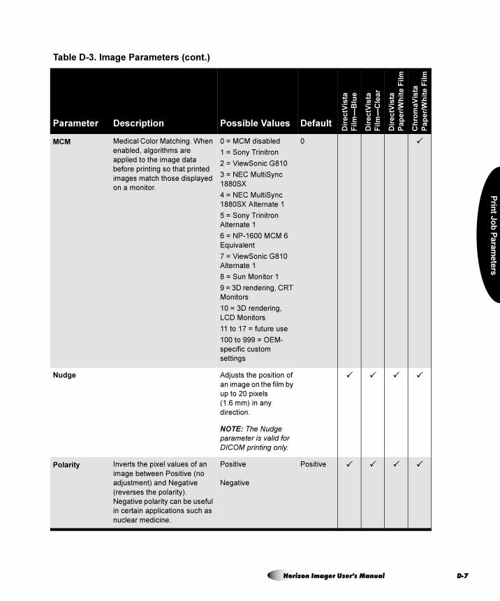
Prin
t Jo
b P
ara
me
ters
MCM Medical Color Matching. When
enabled, algorithms are
applied to the image data
before printing so that printed
images match those displayed
on a monitor.
0 = MCM disabled
1 = Sony Trinitron
2 = ViewSonic G810
3 = NEC MultiSync
1880SX
4 = NEC MultiSync
1880SX Alternate 1
5 = Sony Trinitron
Alternate 1
6 = NP-1600 MCM 6
Equivalent
7 = ViewSonic G810
Alternate 1
8 = Sun Monitor 1
9 = 3D rendering, CRT
Monitors
10 = 3D rendering,
LCD Monitors
11 to 17 = future use
100 to 999 = OEM-
specific custom
settings
0 �
Nudge Adjusts the position of
an image on the film by
up to 20 pixels
(1.6 mm) in any
direction.
NOTE: The Nudge
parameter is valid for
DICOM printing only.
� � � �
Polarity Inverts the pixel values of an
image between Positive (no
adjustment) and Negative
(reverses the polarity).
Negative polarity can be useful
in certain applications such as
nuclear medicine.
Positive
Negative
Positive � � � �
Table D-3. Image Parameters (cont.)
Parameter Description Possible Values Default
Dir
ec
tVis
ta
Fil
m—
Blu
e
Dir
ec
tVis
ta
Fil
m—
Cle
ar
Dir
ec
tVis
ta
Pa
pe
r/W
hit
e F
ilm
Ch
rom
aV
ista
Pa
pe
r/W
hit
e F
ilm
Horizon Imager User’s Manual D-7
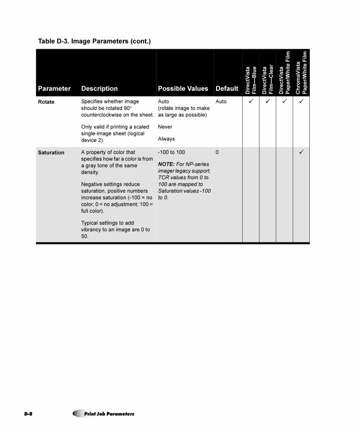
D-8
Rotate Specifies whether image
should be rotated 90°
counterclockwise on the sheet.
Only valid if printing a scaled
single-image sheet (logical
device 2).
Auto
(rotate image to make
as large as possible)
Never
Always
Auto � � � �
Saturation A property of color that
specifies how far a color is from
a gray tone of the same
density.
Negative settings reduce
saturation, positive numbers
increase saturation (-100 = no
color; 0 = no adjustment; 100 =
full color).
Typical settings to add
vibrancy to an image are 0 to
50.
-100 to 100
NOTE: For NP-series
imager legacy support,
TCR values from 0 to
100 are mapped to
Saturation values -100
to 0.
0 �
Table D-3. Image Parameters (cont.)
Parameter Description Possible Values Default
Dir
ec
tVis
ta
Fil
m—
Blu
e
Dir
ec
tVis
ta
Fil
m—
Cle
ar
Dir
ec
tVis
ta
Pa
pe
r/W
hit
e F
ilm
Ch
rom
aV
ista
Pa
pe
r/W
hit
e F
ilm
Print Job Parameters
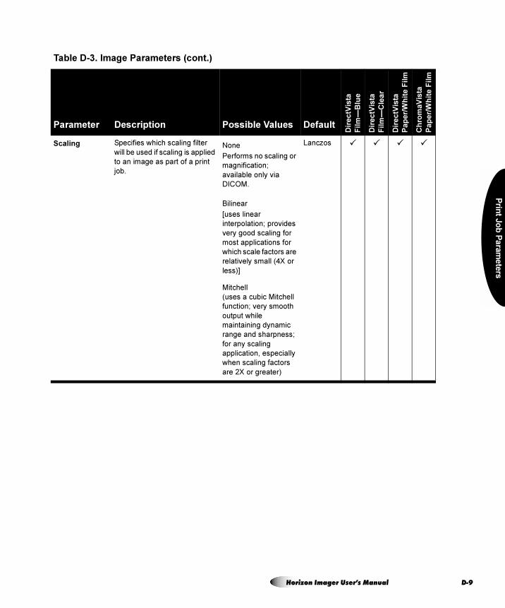
Prin
t Jo
b P
ara
me
ters
Scaling Specifies which scaling filter
will be used if scaling is applied
to an image as part of a print
job.
None
Performs no scaling or
magnification;
available only via
DICOM.
Bilinear
[uses linear
interpolation; provides
very good scaling for
most applications for
which scale factors are
relatively small (4X or
less)]
Mitchell
(uses a cubic Mitchell
function; very smooth
output while
maintaining dynamic
range and sharpness;
for any scaling
application, especially
when scaling factors
are 2X or greater)
Lanczos � � � �
Table D-3. Image Parameters (cont.)
Parameter Description Possible Values Default
Dir
ec
tVis
ta
Fil
m—
Blu
e
Dir
ec
tVis
ta
Fil
m—
Cle
ar
Dir
ec
tVis
ta
Pa
pe
r/W
hit
e F
ilm
Ch
rom
aV
ista
Pa
pe
r/W
hit
e F
ilm
Horizon Imager User’s Manual D-9
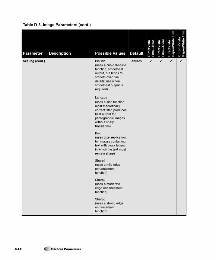
D-1
Scaling (cont.) Bicubic
(uses a cubic B-spline
function; smoothest
output, but tends to
smooth over fine
details; use when
smoothest output is
required)
Lanczos
(uses a sinc function;
most theoretically
correct filter; produces
best output for
photographic images
without sharp
transitions)
Box
(uses pixel replication;
for images containing
text with block letters
in which the text must
remain sharp)
Sharp1
(uses a mild edge
enhancement
function)
Sharp2
(uses a moderate
edge enhancement
function)
Sharp3
(uses a strong edge
enhancement
function)
Lanczos � � � �
Table D-3. Image Parameters (cont.)
Parameter Description Possible Values Default
Dir
ec
tVis
ta
Fil
m—
Blu
e
Dir
ec
tVis
ta
Fil
m—
Cle
ar
Dir
ec
tVis
ta
Pa
pe
r/W
hit
e F
ilm
Ch
rom
aV
ista
Pa
pe
r/W
hit
e F
ilm
0 Print Job Parameters
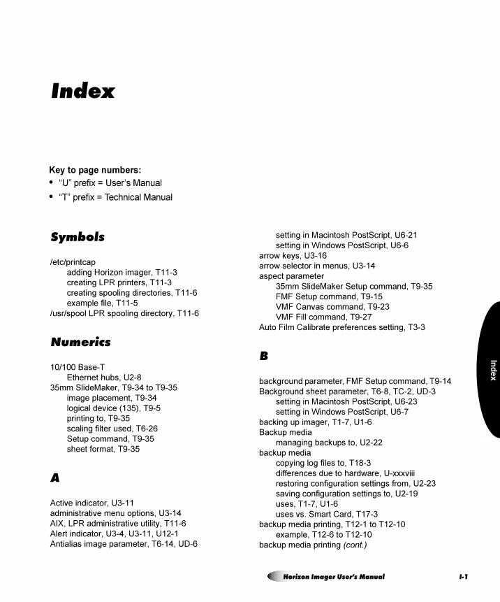
Ind
ex
Index
Key to page numbers:
• “U” prefix = User’s Manual
• “T” prefix = Technical Manual
Symbols
/etc/printcap
adding Horizon imager, T11-3
creating LPR printers, T11-3
creating spooling directories, T11-6
example file, T11-5
/usr/spool LPR spooling directory, T11-6
Numerics
10/100 Base-T
Ethernet hubs, U2-8
35mm SlideMaker, T9-34 to T9-35
image placement, T9-34
logical device (135), T9-5
printing to, T9-35
scaling filter used, T6-26
Setup command, T9-35
sheet format, T9-35
A
Active indicator, U3-11
administrative menu options, U3-14
AIX, LPR administrative utility, T11-6
Alert indicator, U3-4, U3-11, U12-1
Antialias image parameter, T6-14, UD-6
setting in Macintosh PostScript, U6-21
setting in Windows PostScript, U6-6
arrow keys, U3-16
arrow selector in menus, U3-14
aspect parameter
35mm SlideMaker Setup command, T9-35
FMF Setup command, T9-15
VMF Canvas command, T9-23
VMF Fill command, T9-27
Auto Film Calibrate preferences setting, T3-3
B
background parameter, FMF Setup command, T9-14
Background sheet parameter, T6-8, TC-2, UD-3
setting in Macintosh PostScript, U6-23
setting in Windows PostScript, U6-7
backing up imager, T1-7, U1-6
Backup media
managing backups to, U2-22
backup media
copying log files to, T18-3
differences due to hardware, U-xxxviii
restoring configuration settings from, U2-23
saving configuration settings to, U2-19
uses, T1-7, U1-6
uses vs. Smart Card, T17-3
backup media printing, T12-1 to T12-10
example, T12-6 to T12-10
backup media printing (cont.)
Horizon Imager User’s Manual I-1
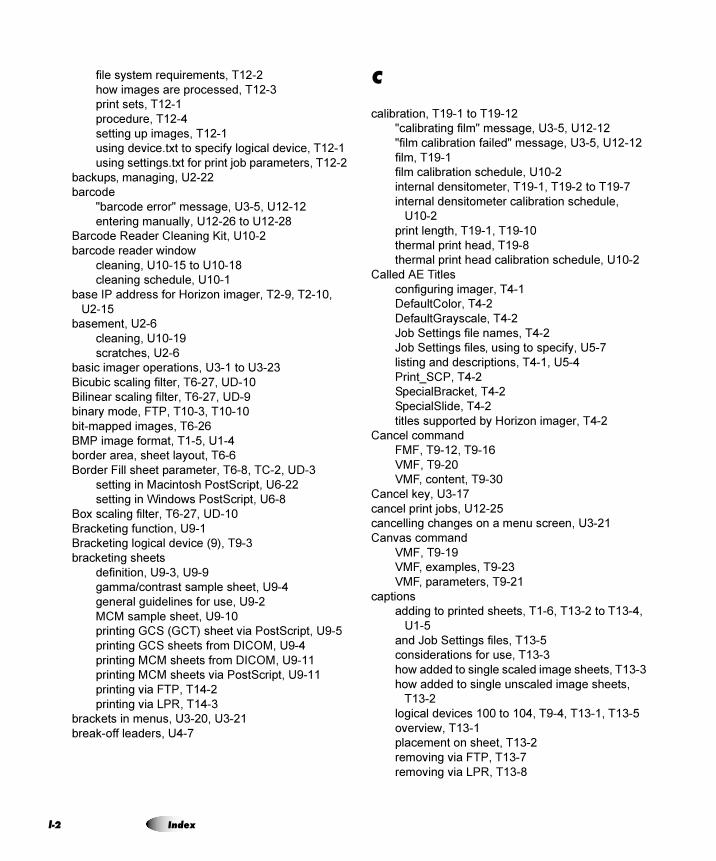
f-2
file system requirements, T12-2
how images are processed, T12-3
print sets, T12-1
procedure, T12-4
setting up images, T12-1
using device.txt to specify logical device, T12-1
using settings.txt for print job parameters, T12-2
backups‚ managing, U2-22
barcode
"barcode error" message, U3-5, U12-12
entering manually, U12-26 to U12-28
Barcode Reader Cleaning Kit, U10-2
barcode reader window
cleaning, U10-15 to U10-18
cleaning schedule, U10-1
base IP address for Horizon imager, T2-9, T2-10,
U2-15
basement, U2-6
cleaning, U10-19
scratches, U2-6
basic imager operations, U3-1 to U3-23
Bicubic scaling filter, T6-27, UD-10
Bilinear scaling filter, T6-27, UD-9
binary mode, FTP, T10-3, T10-10
bit-mapped images, T6-26
BMP image format, T1-5, U1-4
border area, sheet layout, T6-6
Border Fill sheet parameter, T6-8, TC-2, UD-3
setting in Macintosh PostScript, U6-22
setting in Windows PostScript, U6-8
Box scaling filter, T6-27, UD-10
Bracketing function, U9-1
Bracketing logical device (9), T9-3
bracketing sheets
definition, U9-3, U9-9
gamma/contrast sample sheet, U9-4
general guidelines for use, U9-2
MCM sample sheet, U9-10
printing GCS (GCT) sheet via PostScript, U9-5
printing GCS sheets from DICOM, U9-4
printing MCM sheets from DICOM, U9-11
printing MCM sheets via PostScript, U9-11
printing via FTP, T14-2
printing via LPR, T14-3
brackets in menus, U3-20, U3-21
break-off leaders, U4-7
C
calibration, T19-1 to T19-12
"calibrating film" message, U3-5, U12-12
"film calibration failed" message, U3-5, U12-12
film, T19-1
film calibration schedule, U10-2
internal densitometer, T19-1, T19-2 to T19-7
internal densitometer calibration schedule,
U10-2
print length, T19-1, T19-10
thermal print head, T19-8
thermal print head calibration schedule, U10-2
Called AE Titles
configuring imager, T4-1
DefaultColor, T4-2
DefaultGrayscale, T4-2
Job Settings file names, T4-2
Job Settings files‚ using to specify, U5-7
listing and descriptions, T4-1, U5-4
Print_SCP, T4-2
SpecialBracket, T4-2
SpecialSlide, T4-2
titles supported by Horizon imager, T4-2
Cancel command
FMF, T9-12, T9-16
VMF, T9-20
VMF, content, T9-30
Cancel key, U3-17
cancel print jobs, U12-25
cancelling changes on a menu screen, U3-21
Canvas command
VMF, T9-19
VMF, examples, T9-23
VMF, parameters, T9-21
captions
adding to printed sheets, T1-6, T13-2 to T13-4,
U1-5
and Job Settings files, T13-5
considerations for use, T13-3
how added to single scaled image sheets, T13-3
how added to single unscaled image sheets,
T13-2
logical devices 100 to 104, T9-4, T13-1, T13-5
overview, T13-1
placement on sheet, T13-2
removing via FTP, T13-7
removing via LPR, T13-8
Index
Ind
ex
captions(cont.)storing via FTP, T13-5
storing via LPR, T13-6
turning on and off, T13-8
Captions sheet parameter, T6-9, T13-8, TC-2, UD-3
setting in Macintosh PostScript, U6-22
setting in Windows PostScript, U6-8
cassettes
"checking cassettes" message, U3-5, U12-12
"no cassette" message, U3-5, U12-13
barcode, U4-2
changing, U4-4 to U4-5
clearing a jam, U12-16
entering barcode manually, U12-26 to U12-28
loading media, U2-16
media, U4-1 to U4-3
ordering, TA-1
specifying which to use, U4-6
status messages, U3-5, U12-12
supply slots, U4-2
troubleshooting, U12-9
Category 5, RJ-45 cables, U2-8
cell parameter, FMF Setup command, T9-14
center parameter, VMF Fill command, T9-28
changing a supply cassette, U4-4 to U4-5
ChromaVista color media
adjusting image appearance, U9-7
and grayscale images, U9-1
break-off leaders, U4-7
changing the ribbon, U4-8 to U4-11
destroying the ribbon, U4-11
dye-diffusion process, T1-2, U1-2
imaging applications, T1-2, U1-2
ribbon status indications, U3-6, U12-13
types and sizes, TA-1, U4-12
use precautions, U-xxxv
cleaning kits
ordering, U10-2
cleaning precautions, U-xxxiv
cleaning procedures, general, U10-18 to U10-19
clip parameters, VMF Fill command, T9-26
CMY indicator, U3-4
CNFG (configuration) label, U-xxv
Codonics
anonymous FTP site, U12-31
email address, U-xvi
fax number, TA-2
phone numbers, TA-2, U-xvi, U4-13, U10-2
product information, U-xvi
Codonics(cont.)technical support, U12-30
web site, TA-2, U4-13, U10-2
color management
precautions, U-xxxvii
color media, see ChromaVista color media
color parameter
FMF Setup command, T9-14
VMF Canvas command, T9-21
VMF Fill command, T9-24
color ribbon
ordering, TA-1
status indications, U3-6, U12-13
troubleshooting, U12-9
command file
FMF conventions, T9-12
VMF conventions, T9-20
complex network, T2-2 to T2-3
compliance label, U-xxiv
location, U-xvii
components, safe to touch, U-xxix, U-xxxi
compress command, UNIX and Linux, U12-32
confidentiality‚ patient, U4-11
configuration information content, T17-2
Configuration logical device (0), T9-2
configuration number, U-xxv
configuration settings
managing backups, U2-22
restoring, U2-23
saving, U2-19 to U2-21
connecting the imager, U3-2
connectors, U3-2
console connector, U3-2
contrast and gamma, using together, T6-19
contrast curves, T6-16
Contrast image parameter, T6-15, TC-3, UD-6
setting in Macintosh PostScript, U6-23
setting in Windows PostScript, U6-7
contrast parameter, VMF Fill command, T9-28
contrast‚ adjusting, U9-5, U9-7
control panel
adjust display contrast, T3-4
enable/disable display backlight, T3-4
enable/disable key backlight, T3-4
enable/disable key beep, T3-3
illustration, U3-10
imager operating status, U12-1
indicators, U3-11
keys, U3-16 to U3-17
Horizon Imager User’s Manual I-3
f-4
control panel (cont.)menu conventions, U3-21
navigating, U3-18 to U3-21
conventions used in this manual, U-xi to U-xiv
copies parameter
35mm SlideMaker Setup command, T9-35
FMF Setup command, T9-13
VMF Print command, T9-30
Copy Count parameter, setting in Windows
PostScript, U6-6
Coverage sheet parameter, T6-9, TC-2, UD-3
Crop Margin parameter
setting in Macintosh PostScript, U6-21
setting in Windows PostScript, U6-7
crossover cable, U2-9
custom Job Settings files, T8-1, T8-3
copying at control panel, T8-8
creating at control panel, T8-5
creating via text file, T8-11
deleting at control panel, T8-9
deleting via text file, T8-18
editing at control panel, T8-7
example text file content, T8-13
maintaining via text file, T8-18
managing at control panel, T8-4
modifying via text file, T8-18
sending text file via FTP, T8-14
sending text file via LPR, T8-17
viewing at control panel, T8-7
D
date code, U-xxv
DCF, see DICOM Connectivity Framework
Default Media menu
using to specify media for DICOM, T4-7
default print job settings, U8-1 to U8-8
Default User Settings
changing, U8-5 to U8-6
resetting to factory defaults, U8-8
DefaultColor Called AE Title, T4-2
DefaultColor Job Settings file, TB-2, UC-2
DefaultGrayscale Called AE Title, T4-2
DefaultGrayscale Job Settings file, TB-2, UC-2
DEFF image format, T1-5, U1-4
delete print jobs, U12-25
DHCP, see Dynamic Host Configuration Protocol
DICOM
Attributes log file sample, T18-11
attributes mapped to Horizon settings, T4-7 to
T4-8
configuring for printing, T4-1 to T4-9
configuring imager’s Called AE Title, T4-1
configuring imager’s TCP port, T4-1
conformance statement, U5-2
definition, U5-1
DICOM Connectivity Framework (DCF) utility,
T18-10
image format, T1-5, U1-4
media selection process, T6-31
methods for selecting media, T4-3 to T4-7
Print Service Class Provider, U5-3
Print Service Class User, U5-3
printable area of Horizon media, T4-9
supported called AE Titles for imager, T4-2
using Default Media menu to specify media,
T4-7
using DICOM application to specify media, T4-3
to T4-4
using Job Settings files to specify media, T4-6
viewing Attributes log file, T18-10
DICOM applications
configuring, U5-4
Job Settings‚ specifying for, U5-6
printing from, T1-3, U1-3, U5-1 to U5-8
simultaneous connections, T1-4, U1-3
specifying media type and size, U5-5
DICOM Connectivity Framework (DCF) utility,
T18-10
DirectVista grayscale media
adjusting image appearance, U9-5
direct thermal technology, T1-2, U1-2
film calibration, U11-2
imaging applications, T1-2, U1-2
optical density of images, T1-6, U1-5
types and sizes, TA-1, U4-12
use precautions, U-xxxv
Display Backlight preferences setting, T3-4
Display Contrast preferences setting, T3-4
disposal requirements, U-xxxix
Dmax sheet parameter, T6-10, TC-2, UD-4
setting in Macintosh PostScript, U6-22
setting in Windows PostScript, U6-7
Dmax‚ adjusting, U9-5, U9-7
Index
Ind
ex
Dmin sheet parameter, T6-11, TC-2, UD-4
setting in Macintosh PostScript, U6-22
setting in Windows PostScript, U6-7
Document Structuring Conventions (DSC), T5-2
donor guide bar
cleaning procedure, U10-8 to U10-12
cleaning schedule, U10-1
dotted decimal notation, T2-4
Driver Version job parameter
viewing in Macintosh PostScript, U6-21
viewing in Windows PostScript, U6-6
DSC comments
using to define Horizon print parameters, T5-19
to T5-26
DSC, see Document Structuring Conventions
dust, see cleaning procedures and troubleshooting
image quality
dye-diffusion process, T1-2, U1-2
Dynamic Host Configuration Protocol (DHCP), T2-8
E
electronic emissions notices, U-xxvii
ellipses (...) in menu option, U3-18, U3-21
empty parameter, FMF Setup command, T9-14
Enter key, U3-17
Entry Timeout preferences setting, T3-3
error log, U12-1
viewing, U12-28
ESD
caution, U-xxvi
label, U-xxvi
Ethernet
cable jack, U2-8
connecting cable, U2-8
crossover cable, T2-1, U2-9, U2-11
hub, T2-1, U2-8, U2-9, U2-11
European disposal requirements, U-xxxix
Exif image format, T1-5, U1-4
exiting menus, U3-21
F
factory defaults
print job settings, U8-7
Fault indicator, U3-4, U3-11, U12-1
Fault tone, U3-12
Fault Tone preferences setting, T3-3
fax number, Codonics, TA-2
features
enabling, T15-1 to T15-3
keys, T15-1
keys, where stored, T17-2
upgrading, T1-6
file formats, T1-5, U1-4
file transfer
precautions, U-xxxvii
Fill command
VMF, T9-19
VMF, examples, T9-25
VMF, parameters, T9-24
film
path through imager, U12-15
see also media
film calibration, T19-1, U11-1, U11-2
schedule, U10-2
film jams
clearing, U12-14 to U12-21
troubleshooting, U12-6
Film View sheet parameter, T6-12, TC-3, UD-4
setting in Macintosh PostScript, U6-22
setting in Windows PostScript, U6-8
filters, scaling, T6-26 to T6-27
Fixed Multiformatting (FMF)
Cancel command, T9-12, T9-16
command file conventions, T9-12
commands, T9-12
components of sheet, T9-9
creating command files, T9-12
FTP session example, T10-8
FTP, canceling a print job, T10-5
FTP, changing Job Settings file, T10-5
FTP, changing sheet format, T10-5
FTP, printing multiple copies of sheet, T10-4
FTP, sending group of image files, T10-6
LPR example, T11-7
placement of images on sheet, T9-10
Print command, T9-12
Print command parameters, T9-16
printing, T9-9
printing via FTP, T10-2
printing via LPR, T11-7
Setup command, T9-12
Setup command example, T9-15
Setup command parameters, T9-13
Horizon Imager User’s Manual I-5
f-6
Fixed Multiformatting (FMF) (cont.)sheet orientation, T9-11
sheets, U7-3
using in FTP session, T9-16
using with LPR, T9-17
FMF logical device (11 to 99), T9-4
FMF, see Fixed Multiformatting
footprint of imager, T1-3, U1-2
front panel, see control panel
FTP
anonymous, U12-31
bin command, T10-3, T10-10
canceling a print job, T10-5, T10-11
changing Job Settings file, T10-5, T10-11
changing sheet format, T10-5
example sending User Settings file, T7-7
file transfer precautions, U-xxxvii
FMF session example, T10-8
lcd command, T10-6
mput command, T10-4, T10-6
printing bracketing sheet, T14-2
printing images, T1-3, U1-3
printing jobs using User Settings file, T7-10
printing multiple copies of sheet, T10-4
printing overview, T10-1
printing via, U7-1 to U7-4
prompt command, T10-6
put command, T10-4, T10-10
quit command, T10-4, T10-11
removing captions, T13-7
sending group of image files, T10-6
session for single-image and FMF printing,
T10-2
simultaneous connections, T1-5, U1-4
single scaled image session example, T10-7
specifying media type and size, U7-4
storing captions, T13-5
uploading files to Codonics site, U12-31 to
U12-32
using FMF, T9-16
using to send User Settings file, T7-6
using VMF, T9-32
VMF printing, T10-9
VMF session example, T10-12
full bleed image area, sheet layout, T6-6
G
gamma and contrast, using together, T6-19
gamma curves, T6-17
Gamma image parameter, T6-17, TC-3, UD-6
setting in Macintosh PostScript, U6-23
setting in Windows PostScript, U6-7
gamma parameter, VMF Fill command, T9-28
Gamma, Contrast, Saturation Bracketing logical
device (9), T9-3
gamma/contrast bracketing sheet, U9-3
gamma/saturation bracketing sheet, U9-3
gamma‚ adjusting, U9-5, U9-7
gap parameter, FMF Setup command, T9-13
gateway, T2-1, T2-3, U2-11
IP address for Horizon imager, T2-10, U2-12
GDI, see Graphics Device Interface
GIF image format, T1-5, U1-4
Graphics Device Interface (GDI), T5-2
grayscale images and ChromaVista color media,
U9-1
grayscale media, see DirectVista grayscale media
gzip application, UNIX and Linux, U12-32
H
hardware variations
precautions, U-xxxviii
height parameter
VMF Canvas command, T9-21
VMF Fill command, T9-24
help
how displayed, U3-23
message area, U3-14
troubleshooting information, U12-1
Help key, U3-17
hide track, U2-6
Horizon imager
"personality" swap, T1-7
adding to /etc/printcap for LPR, T11-3
adding to a simple network, U2-11
and DHCP, T2-8
assigning multiple IP addresses, T2-9
Index
Ind
ex
Horizon imager (cont.)backup media, T1-7, U1-6
base IP address, T2-9, U2-15
basement, U2-6
basic operations, U3-1 to U3-23
calibrations, T19-1 to T19-12
Called AE Titles used, T4-1, U5-4
changing default media type and size, U8-3 to
U8-4
changing Default User Settings, U8-5 to U8-6
changing PostScript parameters from
Macintosh applications, U6-18 to U6-23
changing PostScript parameters in Windows,
U6-4 to U6-16
cleaning precautions, U-xxxiv
color management precautions, U-xxxvii
compensations made by, T19-8
compliance, U-xxiv
configuration number, U-xxv
critical information, where stored, T17-2
date code, U-xxv
default print job settings, U8-1 to U8-8
DICOM Called AE Title, T4-1
electronic emissions notices, U-xxvii
enabling features, T15-1 to T15-3
error log, U12-1
error log‚ viewing, U12-28
features, T1-2 to T1-7, U1-1 to U1-6
file formats, T1-5, U1-4
file transfer precautions, U-xxxvii
film calibration, U11-2
footprint, T1-3, U1-2
front view, U3-1
general cleaning procedures, U10-18 to U10-19
hardware variations precautions, U-xxxviii
hide track, U2-6
hierarchy of print job parameters, U6-3
hierarchy of print job settings, U5-8
image processing capabilities, T1-6, U1-5
image scaling precautions, U-xxxviii
indications for use, U-xl
installation media, T1-7, U1-6
installing, U2-2 to U2-7
installing as Macintosh printer, T5-7
installing as Windows desktop printer, T5-1
installing PostScript driver file in Macintosh,
T5-7
installing PPD file in Macintosh, T5-7
installing PPD file in Windows, T5-1
Horizon imager (cont.)internal components safe to touch, U-xxix,
U-xxxi
laser warnings, U-xxi
location precautions, U-xxxii
log files, T18-1
main log file, sample listing, T18-9
media use precautions, U-xxxv
models, T1-2, U1-2
modification codes, U-xxv
online help, U12-1
operational state indicators, U3-4
packaging, U2-2
Pause state, U3-22
pausing, U3-22
port number, T4-1, U5-4
power key, U3-3
powering off, U3-7
powering on, U3-3
powering on for first time, U2-9
preparing for installation, U2-1
preparing for shipment, U2-25
preventive maintenance, U10-1 to U10-19
print parameters in PostScript DSC comments,
T5-19 to T5-26
printable area of media, T4-9
processing PostScript DSC comments, T5-2
rear connectors, U3-2
rear view, U3-2
rebooting, U3-9
resetting Default User Settings to factory
defaults, U8-8
resetting media type and size to factory defaults,
U8-7
restoring configuration settings, U2-23
resuming printing, U3-23
safety
precautions, U-xxviii
saving configuration settings, U2-19 to U2-21
saving print settings as defaults in Macintosh
OS 8 and 9, U6-24
saving print settings as presets in Macintosh OS
X, U6-24
selecting media from Macintosh applications,
U6-16
serial number label, U-xxv
setting preferences, T3-1 to T3-4
settings mapped to DICOM attributes, T4-7 to
T4-8
Horizon Imager User’s Manual I-7
f-8
Horizon imager (cont.)sheet layout components, T6-6
sheet layout components illustrated, T6-7
Smart Card, T1-7, T17-1 to T17-4, U1-6
Smart Card panel door, T12-4, T18-3, U2-3,
U2-20
specifications, UB-1 to UB-6
specifying IP addresses, T2-10 to T2-12, U2-12
to U2-16
specifying network speed, T2-12 to T2-13
Status test print, printing, U2-17
status, how to view, T18-7
status, sample listing, T18-7
status, viewing via Telnet, T18-5
supported Called AE Titles, T4-2
swapping for service reasons, T17-1, T17-4,
U2-24
TCP port number, T4-1
technical support, U12-30
Telnet logins, T18-6
temperature warnings, U-xxiii
troubleshooting, T18-1, U12-1 to U12-32
updating software, T16-1 to T16-4
upgrading features, T1-6, U1-5
viewing information about, U12-29
voltage warnings, U-xviii
hubs, Ethernet, U2-8
I
image area
full bleed, T6-6
standard, T6-6
image cropping
PostScript, T5-14
image file formats, U1-4
image file print sets on backup media, T12-1
image mode, FTP, T10-3, T10-10
image parameters, T6-14 to T6-27
Antialias, T6-14, UD-6
changing defaults, U8-5 to U8-6
Contrast, T6-15, TC-3, UD-6
Gamma, T6-17, TC-3, UD-6
MCM, T6-20, TC-3, UD-7
Polarity, T6-22, T6-23, TC-3, UD-7
Rotate, T6-23, TC-4, UD-8
Saturation, T6-24, TC-4, UD-8
Scaling, T6-25, TC-4, UD-9
image parameters (cont.)selection process, T6-28 to T6-32
specifying, T6-1
TCR, TC-4
image processing capabilities, U1-5
image quality
optimizing with calibrations, T19-1, U11-1
image scaling
precautions, U-xxxviii
image settings, U1-5
Image Warnings sheet parameter, T6-12, TC-3,
UD-5
setting in Macintosh PostScript, U6-22
setting in Windows PostScript, U6-8
Imager Info screen, U12-29
Imager Status test print
as information source, U12-2
printing, U2-17
images
adjusting appearance, U2-19, U9-1 to U9-8
adjusting appearance on ChromaVista color
media, U9-7
adjusting appearance on DirectVista grayscale
media, U9-5
enhancing appearance, U2-19
enhancing appearance with gamma and
contrast, T6-19
file formats, T1-5
grayscale images and ChromaVista color
media, U9-1
how placed using 35mm SlideMaker format,
T9-34
how processed for backup media printing, T12-3
LPR single image example, T11-7
pixel-mapped, bit-mapped, raster, T6-26
printing
from backup media, T12-1 to T12-10
printing from backup media, example, T12-6 to
T12-10
printing from backup media, procedure, T12-4
printing single images via LPR, T11-7
printing single scaled, T9-6
printing single scaled via FTP, T9-7, T10-2
printing single scaled via LPR, T9-7
printing single unscaled, T9-7
printing single unscaled via FTP, T9-8, T10-2
printing single unscaled via LPR, T9-8
processing capabilities, T1-6
quality troubleshooting, U12-7
Index
Ind
ex
images (cont.)setting up on backup media for printing, T12-1
settings, T1-6
single unscaled FTP session example, T10-7
sources, T1-3
viewing guidelines, U9-2
imaging media
types and sizes, TA-1
indications for use of the imager, U-xl
indicators
Alert, U3-4, U12-1
CMY, U3-4
color ribbon status, U3-6, U12-13
control panel, U3-11
Fault, U3-4, U12-1
network activity, U3-2
network speed, U3-2
OK, U3-4
ribbon, U3-4
installation
preparing for, U2-1
installation media
differences due to hardware, T16-1, U-xxxviii
interference, radio and television, U-xxvii
internal components safe to touch, U-xxix, U-xxxi
internal densitometer calibration, T19-1, T19-2 to
T19-7, U11-1
blue and clear film, T19-2
entering density values, T19-6
measuring density blocks, T19-5
printing test print, T19-3
recording density block readings, T19-5
resetting to factory default density settings,
T19-7
sample test print, T19-4
schedule, U10-2
Internet service provider, T2-2
IP addresses
assigning multiple addresses to Horizon imager,
T2-9
determining addresses to use, T2-4 to T2-5
format, U2-12
Horizon base address, T2-9, U2-15
resetting to Horizon imager defaults, T2-12
specifying for Horizon imager, T2-10 to T2-12,
U2-12 to U2-16
specifying for other devices on the network,
T2-13, U2-16
IP addresses (cont.)structure, T2-4
subnet masks, T2-6 to T2-8
IP aliasing, T2-9
IRIX, LPR administrative utility, T11-6
ISP, see Internet service provider
J
jams
clearing, U12-14 to U12-21
troubleshooting, U12-6
JFIF image format, T1-5, U1-4
job parameters, T6-3 to T6-5
Media Size, T6-4, TC-2, UD-2
Media Type, T6-3, TC-2, UD-2
Priority, T6-5, TC-2, UD-2
Receive Tray, T6-5, TC-2, UD-2
selection process, T6-28 to T6-32
specifying, T6-1
which supply slot is used, T6-5
Job Settings files
copying at control panel, T8-8
creating at control panel, T8-5
creating via text file, T8-11
custom, T8-1, T8-3, U5-6
deleting at control panel, T8-9
deleting via text file, T8-18
editing at control panel, T8-7
example text file content, T8-13
explanation, T8-1
how imager stores names, T8-11
maintaining via text file, T8-18
managing at control panel, T8-4
modifying via text file, T8-18
name used as Called AE Title, T4-2
overview, T4-5
sending text file via LPR, T8-17
specifying, U5-6 to U5-8
supported parameters, T8-2
system, T8-1, T8-3, TB-1 to TB-3, U5-6, UC-1 to
UC-3
using to specify media in DICOM, T4-6
valid parameter names in text files, TC-1 to TC-4
viewing at control panel, T8-7
JPEG image format, T1-5, U1-4
Horizon Imager User’s Manual I-9
f-1
K
Key Backlight preferences setting, T3-4
Key Beep preferences setting, T3-3
keys
control panel, U-xii, U3-16 to U3-17
L
LAN, see local area networks
Lanczos scaling filter, T6-27, UD-10
landscape parameter
FMF Setup command, T9-13
VMF Canvas command, T9-23
laser warnings, U-xxi
lcd command, FTP, T10-6
leaders, ChromaVista color media, U4-7
LEDs, see indicators
license code
viewing, U12-29
where found, U12-30
Linux
compress command, U12-32
gzip application, U12-32
tar command, U12-32
using LPR, T11-3 to T11-9
loading cassettes, U4-4 to U4-5
loading media, U4-4 to U4-5
loading ribbon, U4-8 to U4-11
local area networks (LAN), T2-1, U2-11
location precautions, U-xxxii
log files, T18-1
copying to backup media, T18-3
DICOM Attributes log file sample, T18-11
error log, U12-1
main log, sample listing, T18-9
viewing DICOM Attributes log file, T18-10
viewing main log at Control Panel, T18-2
viewing main log via Telnet, T18-9
viewing via Telnet, T18-5
log, Telnet login, T18-6
logical devices
0 (Configuration), T9-2
1 (unscaled single image), T9-2
1 (unscaled single image) with PostScript,
T5-12
10 (VMF), T9-4
logical devices (cont.)10 (VMF), FTP example, T9-32
10 (VMF), LPR example, T9-33
100 to 104 (Captions), T9-4, T13-1, T13-5
11 to 99 (FMF), T9-4
11 to 99 (FMF), FTP example, T9-16
11 to 99 (FMF), LPR example, T9-17
135 (35mm SlideMaker), T9-5
135 (35mm SlideMaker), scaling filter used,
T6-26
2 (scaled single image), T9-3
2 (scaled single image) with PostScript, T5-12
300 (Software Update), T9-5
7 (PostScript), T5-4, T5-13, T9-3
8 (MCM Bracketing), T9-3
9 (Gamma, Contrast, Saturation Bracketing),
T9-3, T14-2
and sheet formatting, T9-1
description, T9-2
in device.txt for backup media printing, T12-1
list, T9-2
printing single scaled images, T9-6
printing single scaled images via FTP, T9-7
printing single scaled images via LPR, T9-7
printing single unscaled images, T9-7
printing single unscaled images via FTP, T9-8
printing single unscaled images via LPR, T9-8
specifying, T9-5
logins to imager via Telnet, T18-6
lp command equivalents to lpr commands, T11-9
LPR
/etc/printcap file example, T11-5
/etc/printcap method for creating printers, T11-3
adding Horizon imager to /etc/printcap, T11-3
administrative utility method for creating
printers, T11-6
and logical devices, T11-2
creating /etc/printcap spooling directories,
T11-6
file transfer precautions, U-xxxvii
FMF example, T11-7
lp command equivalents, T11-9
lpr command syntax, UNIX and Linux, T11-7
lpr command syntax, Windows, T11-11
printing bracketing sheet, T14-3
printing images, T1-3, U1-3
printing jobs using User Settings file, T7-10
printing overview, T11-1
printing via, U7-5 to U7-6
0 Index
Ind
ex
LPR (cont.)removing captions, T13-8
simultaneous connections, T1-5, U1-4
single image example, T11-7
specifying media type and size, U7-6
storing captions, T13-6
using FMF, T9-17
using to send User Settings file, T7-8
using VMF, T9-33
using with UNIX and Linux, T11-3 to T11-9
using with Windows, T11-11
VMF example, T11-8
Windows example, T11-11
LUT sheet parameter, T6-13, T19-12, TC-3, UD-5
setting in Macintosh PostScript, U6-22
setting in Windows PostScript, U6-8
M
Macintosh
installing Horizon imager as PostScript printer,
T5-7
installing Horizon PostScript driver, T5-7
installing Horizon PPD, T5-7
printing PostScript files, T5-7
StuffIt application, U12-32
Macintosh applications
changing PostScript parameters, U6-18 to
U6-23
PostScript printing from, U6-16 to U6-24
saving print settings as defaults in OS 8 and 9,
U6-24
saving print settings as presets in OS X, U6-24
selecting media, U6-16
Main Menu, U3-14
displaying administrative options, U3-14
maintenance
recommended schedule, U10-1
margin parameter, FMF Setup command, T9-13
Margin Size parameter
setting in Macintosh PostScript, U6-22
setting in Windows PostScript, U6-7
MCM Bracketing logical device (8), T9-3
MCM bracketing sheet, U9-9
MCM image parameter, T6-20, TC-3, UD-7
setting in Macintosh PostScript, U6-23
setting in Windows PostScript, U6-7
mcm parameter, VMF Fill command, T9-28
MCM, see Medical Color Matching
media
"calibrating film" message, U3-5, U12-12
"checking cassette" message, U3-5, U12-12
"contaminated" message, U3-5, U12-12
"film calibration failed" message, U3-5, U12-12
"media jam" message, U3-5, U12-12
"no cassette" message, U3-5, U12-13
"printing" message, U3-5, U12-13
"unsupported" message, U3-5, U12-13
break-off leaders for ChromaVista color media,
U4-7
cassette-related messages, U3-5, U12-12
cassettes, U4-1 to U4-3
changing default size and type, U8-3 to U8-4
changing Default User Settings for media type,
U8-5 to U8-6
ChromaVista color media and grayscale
images, U9-1
color, T1-3, U1-3
DICOM methods for selecting, T4-3 to T4-7
grayscale, T1-3, U1-3
handling and storage, U4-1 to U4-13
loading cassettes, U2-16
ordering, TA-2, U4-12 to U4-13
page sizes, T5-16
path through imager, U12-15
printable area sizes, T5-16
printable areas, T4-9
resetting Default User Settings to factory
defaults, U8-8
resetting type and size to factory defaults, U8-7
sample selection with UNIX PostScript, T5-11
selecting from Macintosh applications, U6-16
selecting from Windows 2000 and XP
applications, U6-15
selecting from Windows 98 and Me applications,
U6-9
selecting from Windows NT applications, U6-12
selecting with UNIX PostScript, T5-9
selection process for DICOM, T6-31
setting type and size using FTP, U7-4
setting type and size using LPR, U7-6
setting type and size via DICOM, U5-5
setting type and size via PostScript, U6-3
size, type, and count status message, U3-5,
U12-13
supply slots, U4-2
troubleshooting cassettes, U12-9
Horizon Imager User’s Manual I-11
f-1
media (cont.)troubleshooting jams, U12-6
type and size selection process, T6-29
types and sizes, T1-3, TA-1, U1-3, U4-12
use precautions, U-xxxv
media guides, reinstalling, U12-22
Media Size job parameter, T6-4, TC-2, UD-2
Media Type job parameter, T6-3, TC-2, UD-2
Medical Color Matching (MCM), T6-20 to T6-22
definition, U9-9
menu hierarchies, UA-1
Menu key, U3-16
menu options
control panel, U-xii
menu paths, U-xii
menus
cancelling changes, U3-21
conventions, U3-21
ellipses (...) in menu option, U3-18, U3-21
exiting, U3-21
scroll indicator, U3-14
square brackets, U3-20, U3-21
misfeeds, U12-14 to U12-21
Mitchell scaling filter, T6-27, UD-9
mkdir command (UNIX, Linux), T11-6
modem, U2-9
modem connectors, U3-2
modification codes, U-xxv
mput command, FTP, T10-4, T10-6
N
navigating the control panel, U3-18 to U3-21
network activity indicator, U3-2
network connector, U2-8, U3-2
network printing
testing, U2-18
network speed indicator, U3-2
network speed, specifying for Horizon imager, T2-12
to T2-13
networks
adding the Horizon imager, U2-11
simple, U2-11
None (no) scaling filter (DICOM only), T6-27
none scaling filter, UD-9
nosepiece
cleaning procedure, U10-3 to U10-7
cleaning schedule, U10-1
O
offset parameters, VMF Fill command, T9-24, T9-26
OK indicator, U3-4
Online indicator, U3-11
opening the imager top cover
as part of cleaning procedure, U10-3
operational state, U3-4
ordering cleaning kits, U10-2
ordering media, TA-1, U4-12 to U4-13
Orientation parameter, setting in Windows
PostScript, U6-6
Output Bin parameter
setting in Macintosh PostScript, U6-21
setting in Windows PostScript, U6-6
P
packing the imager, U2-25
Page Size parameter, setting in Windows, U6-6
PANTONE, T6-22
paper
path through imager, U12-15
see also media
paper jams
clearing, U12-14 to U12-21
troubleshooting, U12-6
Paper Size parameter
choices in Macintosh PostScript, U6-21
Paper Size parameter, setting in Windows
PostScript, U6-6
parameters
in settings.txt for backup media printing, T12-2
parts safe to touch, U-xxix, U-xxxi
passwords
changing for service login, U2-19
default for service login, T18-6
for Codonics anonymous FTP site, U12-31
for FTP, using to specify Horizon logical device,
T5-8, T7-6, T8-1, T8-14, T9-5, T9-7, T9-8,
T9-16, T9-32, T10-2, T10-9, T13-5, T14-2,
U7-2
for FTP, using to specify Job Settings file, T8-1,
T8-14, T9-16, T9-32, T10-2, T10-9, T14-2
patch cable, U2-9
patient confidentiality, U4-11
Pause key, U3-17
2 Index
Ind
ex
Pause state, U3-22
pausing the imager, U3-22
PCX image format, T1-5, U1-4
phone numbers, Codonics, TA-2
physical media, sheet layout, T6-6
pick tires
cleaning procedure, U10-13 to U10-15
cleaning schedule, U10-1
pixelation, T1-6, U1-5
pixel-mapped images, T6-26
PKZIP, U12-32
Place command
VMF, T9-20
VMF, examples, T9-29
VMF, parameters, T9-25
platen
cleaning procedure, U10-8 to U10-12
cleaning schedule, U10-1
Platen and Print Head Cleaning Kit, U10-2
PNM image format, T1-5, U1-4
polarity and NP series legacy support, T6-23
Polarity image parameter, T6-22, T6-23, TC-3, UD-7
setting in Macintosh PostScript, U6-23
setting in Windows PostScript, U6-7
port number, T4-1, U5-4
portrait parameter
FMF Setup command, T9-13
VMF Canvas command, T9-23
PostScript, T1-5, U1-4
and captions, T13-3
changing parameters from Macintosh, U6-18 to
U6-23
changing parameters from Windows, U6-4 to
U6-16
eliminating white margins, T5-14
Horizon logical device 7, T5-4
Horizon media page sizes, T5-16
Horizon media printable area sizes, T5-16
image cropping, T5-14
installing Horizon driver in Macintosh, T5-7
installing Horizon driver in Windows, T5-1
installing Horizon PPD in Macintosh, T5-7
installing Horizon PPD in Windows, T5-1
introduction, U6-2
logical device (7), T9-3
logical devices that support PostScript, T5-12
non-standard PostScript, T5-2 to T5-6
printing from Macintosh, T5-7
PostScript (cont.)printing from Macintosh applications, U6-16 to
U6-24
printing from UNIX, T5-8 to T5-11
printing from Windows, T5-1 to T5-6
printing from Windows applications, U6-4 to
U6-16
printing using UNIX FTP, T5-8
printing using UNIX LPR, T5-8
printing via, T1-3, U1-3, U6-1 to U6-24
sample media selection from UNIX, T5-11
saving print settings as defaults in Macintosh
OS 8 and 9, U6-24
saving print settings as presets in Macintosh OS
X, U6-24
selecting media from Macintosh applications,
U6-16
selecting media in UNIX, T5-9
settings that can be changed, U6-6, U6-21
simultaneous connections, T1-4, U1-3
solution to non-standard PostScript, T5-4
specifying media type and size, U6-3
power key, U3-3
Power menu, bypassing, U3-7
power rocker switch, U2-9
powering off the Horizon imager, U3-7
powering on for first time, U2-9
powering on the Horizon imager, U3-3
precautions
cleaning, U-xxxiv
color management, U-xxxvii
file transfer via FTP and LPR, U-xxxvii
hardware variations, U-xxxviii
image scaling, U-xxxviii
location, U-xxxii
media use, U-xxxv
safety, U-xxviii
preferences
Auto Film Calibrate, T3-3
Display Backlight, T3-4
Display Contrast, T3-4
Entry Timeout, T3-3
Fault Tone, T3-3
Key Backlight, T3-4
Key Beep, T3-3
resetting to factory defaults, T3-2
Resume Timeout, T3-3
setting, T3-1 to T3-4
Speaker Volume, T3-3
Horizon Imager User’s Manual I-13
f-1
preventive maintenance, U10-1 to U10-19
recommended schedule, U10-1
Print command
FMF, T9-12
FMF, parameters, T9-16
VMF, T9-20
VMF, parameters, T9-30
Print FMF After Job parameter
setting in Macintosh PostScript, U6-22
setting in Windows PostScript, U6-7
print head, see thermal print head
print job parameters
in settings.txt for backup media printing, T12-2
resetting to factory default settings, U8-7
summary, UD-1 to UD-10
print job settings
specifying, U5-6
print jobs
purging, U12-25
print length calibration, T19-1, T19-10, U11-1
procedure, T19-10
resetting to factory default setting, T19-11
print parameters
default settings, U8-1 to U8-8
print parameters in PostScript DSC comments,
T5-19 to T5-26
print quality problems, U12-7
Print Service Class Provider, U5-3
Called AE Title, U5-3
Print Service Class User, U5-3
Calling AE Title, U5-3
print sets on backup media, T12-1
Print_SCP Called AE Title, T4-2
Print_SCP Job Settings file, TB-2, UC-2
printcap, see /etc/printcap
printer, see Horizon imager
printing
from DICOM applications, U5-1 to U5-8
resuming, U3-23
troubleshooting, U12-2
via FTP, U7-1 to U7-4
via LPR, U7-5 to U7-6
via PostScript, U6-1 to U6-24
Priority job parameter, T6-5, TC-2, UD-2
setting in Macintosh PostScript, U6-23
setting in Windows PostScript, U6-8
prompt command, FTP, T10-6
purge print jobs, U12-25
purpose of User’s Manual, U-xv
put command, FTP, T10-4, T10-10
Q
quality problems with prints, U12-7
quit command, FTP, T10-4, T10-11
R
radio interference, U-xxvi, U-xxvii
RAS image format, T1-5, U1-4
raster images, T6-26
rebooting, U3-9
Receive Tray job parameter, T6-5, TC-2, UD-2
receive trays
cleaning, U10-18
overview, U4-3
removing jams, U12-14 to U12-21
Reset Network Settings menu option, T2-12
Resume Timeout preferences setting, T3-3
resuming printing, U3-23
returning the imager to Codonics, U2-25
RGB values
specifying, T6-8
ribbon
changing, U4-8 to U4-11
destroying, U4-11
indicator, U3-4
loading, U2-16
ordering, TA-1
RJ-45 cables, Category 5, U2-8
Rotate image parameter, T6-23, TC-4, UD-8
rotate parameter, VMF Fill command, T9-28
router, T2-3
S
SA-2000‚ printing from, T1-3, U1-3
Safe Label System
disposal requirements, U-xxxix
safety
internal components, safe to touch, U-xxix,
U-xxxi
location of labels, U-xvii
precautions, U-xxviii
4 Index
Ind
ex
saturation, T6-24 to T6-25
adjusting, U9-7
Saturation image parameter, T6-24, TC-4, UD-8
guidelines for selecting setting, U9-8
setting in Macintosh PostScript, U6-23
setting in Windows PostScript, U6-7
saturation parameter, VMF Fill command, T9-28
scale parameter
FMF Setup command, T9-14
VMF Canvas command, T9-22
VMF Fill command, T9-27
scaled single-image logical device (2), T9-3
scaling, T6-25 to T6-27
filters, T6-26 to T6-27
scaling algorithms, T1-6, U1-5
Scaling image parameter, T6-25, TC-4, UD-9
setting in Macintosh PostScript, U6-23
setting in Windows PostScript, U6-7
scratches
on imager basement, U2-6, U10-19
on sheet, U12-7
scroll indicator in menus, U3-14
selector arrow in menus, U3-14
sensitometry compensation, T19-12
serial number
viewing, U12-29
where found, U12-30
serial number label, U-xxv
service login
changing password, U2-19
default password, T18-6
using to view User Settings file, T7-8
service, Telnet login, T18-6
settings
print jobs, defaults, U8-1 to U8-8
Setup command
35mm SlideMaker, T9-35
FMF, T9-12
FMF, example, T9-15
FMF, parameters, T9-13
SGI image format, T1-5, U1-4
Sharp scaling filters, T6-27, UD-10
Sheet Coverage parameter
setting in Macintosh PostScript, U6-22
setting in Windows PostScript, U6-8
sheet formatting
35mm SlideMaker, T9-35
and logical devices, T9-1
caption placement, T13-2
sheet formatting (cont.)Fixed Multiformatting (FMF), T9-9
how captions are added, T13-2 to T13-4
Variable Multiformatting (VMF), T9-18
sheet jams
clearing, U12-14 to U12-21
troubleshooting, U12-6
sheet layout components, T6-6
illustrated, T6-7
Sheet Layout parameter
setting in Macintosh PostScript, U6-21
setting in Windows PostScript, U6-6
sheet parameters, T6-6 to T6-13
Background, T6-8, TC-2, UD-3
Border Fill, T6-8, TC-2, UD-3
Captions, T6-9, T13-8, TC-2, UD-3
changing defaults, U8-5 to U8-6
Coverage, T6-9, TC-2, UD-3
Dmax, T6-10, TC-2, UD-4
Dmin, T6-11, TC-2, UD-4
Film View, T6-12, TC-3, UD-4
Image Warnings, T6-12, TC-3, UD-5
LUT, T6-13, T19-12, TC-3, UD-5
selection process, T6-28 to T6-32
specifying, T6-1
sheet settings, T1-6, U1-5
sheets
path through imager, U12-15
shipping damage, U12-2
shipping the imager, U2-25
simple network
with Ethernet crossover cable, T2-2, U2-12
with Ethernet hub, T2-2, U2-11
single images
printing via LPR, T11-7
single scaled images
FTP session example, T10-7
FTP, canceling a print job, T10-5
FTP, changing Job Settings file, T10-5
FTP, changing sheet format, T10-5
FTP, printing multiple copies of sheet, T10-4
FTP, sending group of image files, T10-6
how captions are added to sheet, T13-3
printing, T9-6
printing via FTP, T9-7, T10-2
printing via LPR, T9-7
single unscaled images
FTP, canceling a print job, T10-5
FTP, changing Job Settings file, T10-5
Horizon Imager User’s Manual I-15
f-1
single unscaled images (cont.)FTP, changing sheet format, T10-5
FTP, printing multiple copies of sheet, T10-4
FTP, sending group of image files, T10-6
how captions are added to sheet, T13-2
printing, T9-7
printing via FTP, T9-8, T10-2
printing via LPR, T9-8
Skip Blank Pages parameter
setting in Macintosh PostScript, U6-22
setting in Windows PostScript, U6-7
SlideMaker, see 35mm SlideMaker
Smart Card, T1-7, T17-1 to T17-4, U1-6
events that cause an update, T17-2
information stored, T17-2
panel door, T12-4, T18-3, U2-3, U2-20
swapping with another imager, T17-4, U2-24
uses vs. backup media, T17-3
software
installation, T16-1 to T16-4
updating, T1-7, T16-1 to T16-4, U1-6
Software License Code, T17-2
Software Update logical device (300), T9-5
Solaris, LPR administrative utility, T11-6
Speaker Volume preferences setting, T3-3
SpecialBracket Called AE Title, T4-2
SpecialSlide Called AE Title, T4-2
specifications, UB-1 to UB-6
square brackets in menus, U3-20, U3-21
standard image area, sheet layout, T6-6
startup
troubleshooting, U12-2
status
cassette-related messages, U3-5, U12-12
color ribbon indicator, U3-6, U12-13
how to view, T18-7
printing Status test print, U2-17
sample listing, T18-7
Telnet login, T18-6
status information
on Imager Status test print, U12-2
viewing via Telnet, T18-5
what is included, T18-5
Status screen
description, U3-4, U3-13
returning to from menus, U3-21
Status test print, U12-2
printing, U2-17
Status window
Alert messages, U3-12
description, U3-4, U3-13
Fault messages, U3-12
StuffIt application, U12-32
subnet mask, T2-6 to T2-8, U2-12
setting for Horizon imager, T2-10
subnetworks, T2-6 to T2-8
Sun Raster image (RAS) format, T1-5
supply cassettes, see cassettes
supply slots, U4-2
determining, T6-5
status, U4-3
Supply window, description, U3-4, U3-13
swap imager, U2-24
system Job Settings files, T8-1, T8-3, TB-1 to TB-3,
UC-1 to UC-3
T
tar command, UNIX and Linux, U12-32
TCP port number, T4-1, U5-4
for Horizon imager, T4-1
TCR image parameter, TC-4
TCR, see True Color Rendering
technical support, U12-30
television interference, U-xxvii
Telnet
imager logins, T18-6
using to view User Settings file, T7-8
viewing log files and imager status, T18-5
viewing main log file, T18-9
temperature warnings, U-xxiii
test print
Imager Status, U12-2
printing, U2-17
testing network printing, U2-18
TGA image format, T1-5, U1-4
thermal effects compensation, T19-12
thermal print head, T19-1
calibration, T19-1, T19-8, U11-1
calibration frequency, T19-8
calibration procedure, T19-9
calibration schedule, U10-2
calibration, resetting to factory settings, T19-9
cleaning procedure, U10-3 to U10-7
cleaning schedule, U10-1
compensation, T19-8
6 Index
Ind
ex
TIFF image format, T1-5, U1-4
troubleshooting, U12-1 to U12-32
cassettes, U12-9
color ribbon, U12-9
DICOM Attributes log file, sample, T18-11
DICOM Attributes log file, viewing, T18-10
image quality, U12-7
log files, T18-1
log files, copying to backup media, T18-3
log files, viewing via Telnet, T18-5
main log file, sample listing, T18-9
main log file, viewing via Telnet, T18-9
main log, viewing at Control Panel, T18-2
miscellaneous, U12-11
print jobs, U12-2
sheet jams, U12-6
startup, U12-2
status, how to view, T18-7
status, sample listing, T18-7
status, viewing via Telnet, T18-5
True Color Rendering (TCR) and saturation, T6-24
TRUMATCH, T6-22
turning off the imager, U3-7
turning on the imager, U3-3
U
UNIX
compress command, U12-32
gzip application, U12-32
printing PostScript files, T5-8 to T5-11
printing PostScript files using FTP, T5-8
printing PostScript files using LPR, T5-8
sample media selection for PostScript printing,
T5-11
selecting media for PostScript printing, T5-9
tar command, U12-32
using LPR, T11-3 to T11-9
UNIX BSD, T11-9
UNIX System V, T11-9
unscaled single-image logical device (1), T9-2
unshielded twisted pair (UTP) cable, U2-8
updating software, T1-7, T16-1 to T16-4, U1-6
UPS (uninterruptible power supply), U2-5
UPS connector, U3-2
USB flash drive
uses, T1-7
USB flash drive port
uses, T16-1, U-xxxviii, U1-6
USB flash drives, T16-1, U-xxxviii
use of the imager‚ indications for, U-xl
User Settings files
creating, T7-3 to T7-9
creating the text file, T7-3
deleting, T7-9
example file content, T7-5
FTP session example, T7-7
maintaining, T7-8
modifying, T7-9
parameters that can be specified, T7-2
sending via FTP, T7-6
sending via LPR, T7-8
using with print job via FTP, T7-10
using with print job via LPR, T7-10
viewing current settings for a user, T7-8
when used, T7-1
User’s Manual, purpose, U-xv
V
Variable Multiformatting (VMF)
Cancel command, T9-20
Cancel command content, T9-30
Canvas command, T9-19
Canvas command examples, T9-23
Canvas command parameters, T9-21
command file conventions, T9-20
command session example, T9-30
commands, T9-19
components of sheet, T9-18
creating command files, T9-19
Fill command, T9-19
Fill command examples, T9-25
Fill command parameters, T9-24
FTP session example, T10-12
FTP, canceling a print job, T10-11
FTP, changing Job Settings file, T10-11
LPR example, T11-8
Place command, T9-20
Place command examples, T9-29
Place command parameters, T9-25
Print command, T9-20
Print command parameters, T9-30
printing, T9-18
Horizon Imager User’s Manual I-17
f-1
Variable Multiformatting (cont.)printing via FTP, T10-9
using in FTP session, T9-32
using with LPR, T9-33
viewing images, guidelines, U9-2
VMF logical device (10), T9-4
VMF, see Variable Multiformatting
voltage warnings, U-xviii
W
WAN, see wide area networks
warnings
laser, U-xxi
temperature, U-xxiii
voltage, U-xviii
web site, Codonics, TA-2
WEEE (Waste Electrical and Electronic Equipment)
disposal directive, U-xl
white margins, eliminating in PostScript, T5-14
wide area networks (WAN), T2-1, U2-11
width parameter
VMF Canvas command, T9-21
VMF Fill command, T9-24
Windows
applications generating non-standard
PostScript, T5-2 to T5-6
installing Horizon imager as PostScript desktop
printer, T5-1
Windows (cont.)installing Horizon PostScript driver, T5-1
installing Horizon PPD, T5-1
LPR example, T11-11
PKZIP compression format, U12-32
printing PostScript files, T5-1 to T5-6
solution to non-standard PostScript, T5-4
using LPR, T11-11
Windows applications
changing PostScript parameters, U6-4 to U6-16
PostScript printing from, U6-4 to U6-16
printing from, T1-3, U1-3
Windows FAT file system, and backup media
printing, T12-2
X
XWD image format, T1-5, U1-4
Z
Zip disks, T16-1, U-xxxviii
saving configuration settings to, U2-19
Zip drive
and Smart Card panel door, T12-4, T18-3,
U2-20
uses, T1-7, T16-1, U-xxxviii, U1-6
8 Index