Embed Size (px)
Citation preview

EA OLEDS102-6
INCL CONTROLLER SSD1306B FOR SPI AND I²C
ELECTRONIC ASSEMBLY GmbH Fon: +49 (0)8105-7780 90 Issue 01.2018 Zeppelinstraße 19 Fax: +49 (0)8105-7780 99 D-82205 Gilching e-Mail: [email protected] Germany Web: www.lcd-module.de
Dimension 39x41x3.3mm
FEATURES 102X64 DOTS (RELATES TO 8x17 CHARACTER OR 4x12 LARGE CHARACTER) HIGH CONTRAST OLED DISPLAY INTEGRATED CONTROLLER SSD1306B SPI INTERFACE: MOSI, CLK, CS, D/C I²C INTERFACE: SDA, SCL WIDE TEMPERATURE RANGE (TOP -40°C - +80°C) NO MOUNTING REQUIRED: JUST PUT INTO PCB 3 VERSIONS (WITH / W.O. POLARISOR AND PROTECTION GLASS) IN VARIOUS COLORS) FAST RESPONSE TIME, NO AFTERGLOW
ORDERING CODES GRAPHIC 102x64, yellow, black background, incl. protection glass EA OLEDM102-6GGA GRAPHIC 102x64, yellow, black background, w./o. protection glass EA OLEDM102-6LGA GRAPHIC 102x64, white, black background, w./o. protection glass EA OLEDS102-6LWA
WITH A MINIMUM ORDER QTY. OF 500 PCS.
GRAPHIC 128x64, with Polarisor (Standard) EA OLEDS102-6LXA X: G = Yellow B = Blue R = Red
ACCESSORIES
TEST BOARD WITH USB-INTERFACE EA 9781-1USB SOCKET 4.8MM HOCH (2 PCS. ARE REQUIRED) EA FL-14P TOUCHPANEL, 4-WIRE ANALOGUE SELF-ADHESIVE EA TOUCH102-1*) ZIFF CONNECTOR FOR TOUCH, BOTTOM CONTACT EA WF100-04S
*) ONLY IN COMBINATION WITH EA OLEDS102-6GGA.

EA OLEDS102-6
Printing and typographical errors reserved. Page 2 ELECTRONIC ASSEMBLY reserves the right to change specifications without prior notice.
EA OLED SERIES With its EA OLED series ELECTRONIC ASSEMBLY launched worldwide the first display family with OLED-technology for direct mounting and soldering. In comparison to standard displays there’s no FFC/FPC cable/connector that may lose contact, this OLED series will be soldered directly or put into a standard 2.54 mm precision socket. It is designed for compact handheld equipment and provides a lot real advantages:
- Extreme compact with a large viewing area - Super flat with 2.4 mm (without frontal protection glass) - SPI and I²C interface - Simple mounting with direct soldering - Ex stock available from 1 pc. off - Long life time (80,000 h for yellow) - Wide temperature range (-40..+80°C) - Fast response time (10µs), no afterglow
VERSIONS The EA OLEDS102-6 is available in 3 different versions: EA OLEDS102-6GGA / Allround This module is perfect for rough environment. An additional frontal glass protects the display against scratch, shock and UV light. Thanks to its integrated polariser there’s no need for an additionally smoked glass. EA OLEDS102-6LGA and -6LWA / Flat This module is the standard module and does fit for the most applications. The flat design (2.4 mm) makes the display perfect for smallest equipment. The background is always deep black for best contrast.
COLORS (CUSTOM MADE) The standard colors are yellow and white. The flat version EA OLEDS102-6LGA is on customers request available in 3 more colors. The minimum order quantity is 500 pcs., lead time is about 20 weeks. Samples in other sizes (e.g. EA OLEDL128) are normally available ex stock. Interface and software are 100% compatible. The yellow color provides highest brightness and longest life time.
EA OLEDS102-6LEA
EA OLEDS102-6LRA
EA OLEDS102-6LBA
EA OLEDS102-6
Printing and typographical errors reserved. Page 3 ELECTRONIC ASSEMBLY reserves the right to change specifications without prior notice.
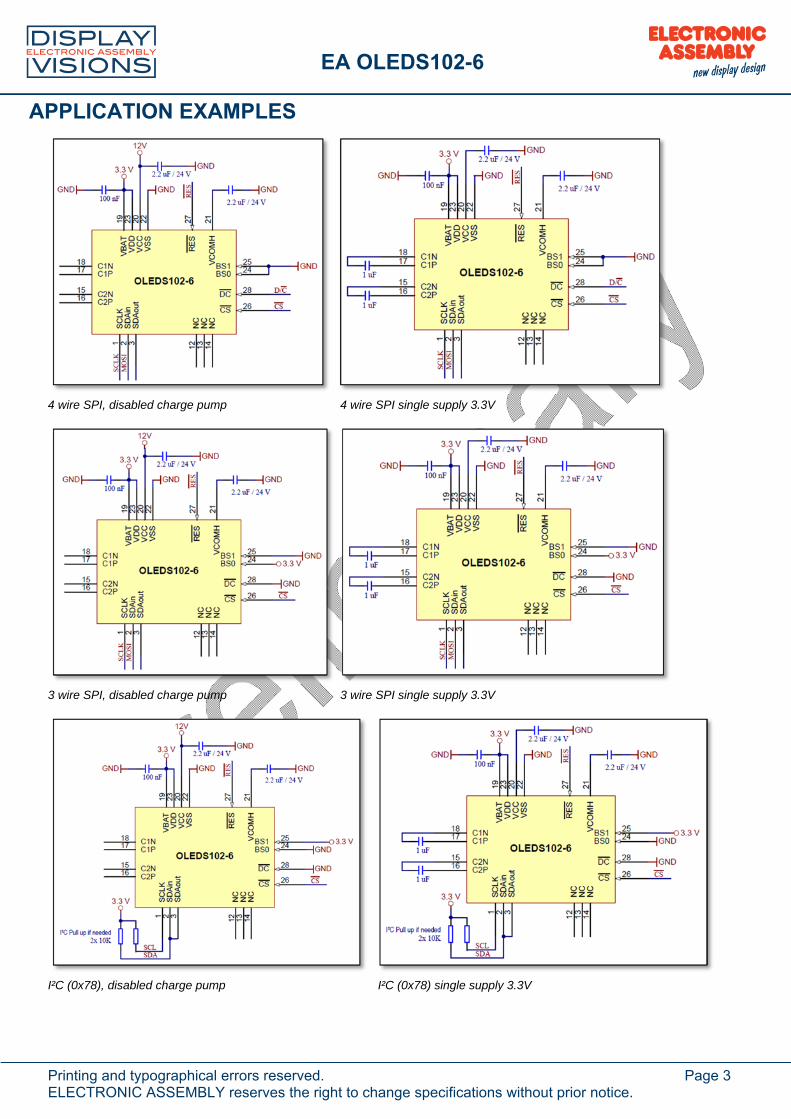
APPLICATION EXAMPLES
4 wire SPI, disabled charge pump 4 wire SPI single supply 3.3V
3 wire SPI, disabled charge pump 3 wire SPI single supply 3.3V
I²C (0x78), disabled charge pump I²C (0x78) single supply 3.3V

EA OLEDS102-6
Printing and typographical errors reserved. Page 4 ELECTRONIC ASSEMBLY reserves the right to change specifications without prior notice.
POWER SUPPLY GENERATOR
Voltage converter 3.3V-12 V (FAN5331, LT1935)

EA OLEDS102-6
Printing and typographical errors reserved. Page 5 ELECTRONIC ASSEMBLY reserves the right to change specifications without prior notice.
DATA TRANSFER 4-WIRE SPI (8 BIT) Data transmission for SPI is unidirectional, that means that data can only be written, there’s no data read option. Selection for writing data or command is done with the D/C line. A busy check is not necessary at all. Clock rate may be up to 10 MHz. Data transmission is based on SPI mode 3, MSB first. For more details please refer to the controllers data sheet SSD1309.
DATA TRANSFER 4-WIRE SPI (9 BIT) Data transmission for SPI is unidirectional, that means that data can only be written, there’s no data read option. Selection for writing data or command is done with the first bit of the 9 bit data transfer. A busy check is not necessary at all. Clock rate may be up to 10 MHz. Data transmission is based on SPI mode 3, MSB first (9 bit). For more details please refer to the controllers data sheet SSD1309.
DATA TRANSFER I²C The I²C mode provides a bi-directional data transmission: That means that data can be written and read. With the pin SA0 the I²C address can be changed (L: 0x78 or 0x3C, H:0x7A or 0x3D). So up to 2 displays may be driven on 1 bus. The clock rate may be up to 400 KHz. Please make sure when defining the pull-up resistors that the internal resistance of the display is 600..1000 . This affects the low level when reading data and ACK bit. Attention: When reading data, after the command for page- or column address there need to be a dummy read (discard the first byte).
Control byte: Co (Continuation bit) = 0 Display data do follow; 1 refer D/C bit

EA OLEDS102-6
Printing and typographical errors reserved. Page 6 ELECTRONIC ASSEMBLY reserves the right to change specifications without prior notice.
GRAPHIC RAM The EA OLEDS102-6 comes with an integrated display RAM. Each byte represents 8 dots. For more details please refer to the controllers data sheet SSD1306B, available on our website at http://www.lcd-module.de/fileadmin/eng/pdf/zubehoer/SSD1306B_1.1.pdf.
COMMAND TABLE (ABSTRACT) This is a collection of the most important commands. The data sheet SSD1309 provides the full list plus a detailed description.
Command D/C
Command Code Description
Hex D7 D6 D5 D4 D3 D2 D1 D0 Contrast Control
0 0
81 7F
1 A7
0 A6
0 A5
0 A4
0 A3
0 A2
0 A1
1 A0
Double byte command to select 1 out of 256 contrast steps. Contrast increases as the value increases.
Display On / Off
0 AE/ AF
1 0 1 0 1 1 1 X0 X0=0: Display OFF (sleep mode) (RESET) X0=1: Display ON in normal mode
Set Column address
0 0 0
21 0 7F
0 A7
B7
0 A6
B6
1 A5
B5
0 A4
B4
0 A3
B3
0 A2
B2
0 A1
B1
1 A0
B0
Setup column start and end address A[7:0] : Column start address, range : 0-127d, (RESET = 0) B[7:0]: Column end address, range : 0-127d, RESET = 127) Note: This command is only for horizontal or vertical addressing mode.
Set Page address
0 0 0
22 0 7
0 X X
0 X X
1 X X
0 X X
0 X X
0 A2
B2
1 A1
B1
0 A0
B0
Setup page start and end address A[2:0] : Page start Address, range : 0-7d, (RESET = 0) B[2:0] : Page end Address, range : 0-7d, (RESET = 7) Note: This command is only for horizontal or vertical addressing mode.
Display Start Line
0 40 – 7F
0 1 A5 A4 A3 A2 A1 A0 Set display RAM display start line register from 0-63 using X5X3X2X1X0. Display start line register is reset to 0 during RESET.
Segment remap
0 A0/ A1
1 0 1 0 0 0 0 X0 X0=0: column address 0 is mapped to SEG0 (RESET) X0=1: column address 127 is mapped to SEG0
Com output scan direction
0 C0/ C8
1 1 0 0 X3 0 0 0 X3=0: normal mode (RESET) Scan from COM0 to COM[N –1] X3=1: remapped mode. Scan from COM[N-1] to COM0 Where N is the Multiplex ratio
RAM Data 1 XX D7 D6 D5 D4 D3 D2 D1 D0 D7-D0 is written to RAM.

EA OLEDS102-6
Printing and typographical errors reserved. Page 7 ELECTRONIC ASSEMBLY reserves the right to change specifications without prior notice.
INITIALISATION EXAMPLE void init_OLEDS102(void) { send_command(0x40); //Set Display start line send_command(0xA0); //Bottom View no Segment remap send_command(0xC0); //Bottom View COM scan direction normal send_command(0x2E); //StartColumnAddress send_command(0x8D); send_command(0x10); //Charge Pump Setting send_command(0x20); send_command(0x02); //Set Memory AddressMode send_command(0x81); send_command(0xFF); //Set Brightness send_command(0xD5); send_command(0x40); //Set Display Clock Divide send_command(0xD9); send_command(0xF1); //Set Precharge Periode send_command(0xAD); send_command(0x30); //Set Internal Ref send_command(0xAF); //Display on }
ACCESSORY: SOCKET EA FL-14P Using a 14-pin socket makes the display replaceable and adapts the height. Those socket may also be soldered automatically by wave soldering or reflow process. Each display requires 2 pcs.
ACCESSORY: TOUCHPANEL EA TOUCH102-1 As an accessory there is an analogue touchpanel available. It comes with a self-adhesive glue on its rear side. Connection is done via FFC, pitch 1.0 mm. Any standard ZIFF connector can be used (e.g. EA WF100-04S). Bending radius is minimum 5 mm. Interfacing to a processor can be either done by an external touch panel controller or with a controller that is featured with analogue input. The touch panel is similar to a potentiometer: connecting a voltage of e.g. 3.3 V to the pins Top-Bottom makes it possible to read out a voltage on pin Left or Right which is linear to the Y-coordinate of the pressed point. The X-coordinate will result when the voltage will be supplied to Left-Right and measurement is done at Top or Bottom. The pinout of the connecting cable is shown in the drawing. Only in combination with the EA OLEDS102-6GGA.
ACCESSORY: ZIFF CONNECTOR EA WF100-04S The ZIFF connector matches perfect to the touch panel EA TOUCH128-1. It provides 4 pins with 1.0 mm pitch. Connection is bottom contact. Top contact version is called EA WF100-04T.

EA OLEDS102-6
Printing and typographical errors reserved. Page 8 ELECTRONIC ASSEMBLY reserves the right to change specifications without prior notice.
SPECIFICATION
Value Condition min typ max unit
Operating Temperature -40 +80 °C
Storage Temperature -40 +80 °C
Storage Humidity <40°C 90 %RH
Operating Voltage VDD (logic supply) 1.8 3.0 3.3 V
Operating Voltage VCC (OLED supply) 12.0 12.5 13.0 V
High Logic input level 0.8 x VDD V
Low Logic input level 0.2 x VDD V
Power Supply1) All Pixel on tbd mA
50 % Pixel on 25 45 mA
All Pixel off tbd mA
1) VDD= 3.3V, incl. booster FAN5331 with VCC= 12.5V
OPTICAL DATA
Item Symbol Condition min typ max Unit
View Angle (V)θ CR≧2000 160 170 deg (H)φ CR≧2000 160 170 deg
Contrast Ratio CR Dark Room 2000:1
Response Time T rise 10 µs T fall 10 µs
Luminance1) L -6GGA / -6LGA 90 100 cd/m² CIE 1931 x(Yellow) Dark Room 0.45 0.47 0.49 CIE 1931 y(Yellow) Dark Room 0.48 0.50 0.52 Operating Life Time2)
Ta=25°C 50% chess board
50000 hrs
1) VDD= 3.3V, incl. booster 1) VDD= 3.3V, incl. booster FAN5331 with VCC= 12.5V 2) Operating life time is defined the amount of time until the luminance has decayed to 50% of the initial value. Screen saving mode is recommended to extend life time .

EA OLEDS102-6
Printing and typographical errors reserved. Page 9 ELECTRONIC ASSEMBLY reserves the right to change specifications without prior notice.
DIMENSIONS EA OLEDS102-6
Pin Symbol Pin Symbol Description
1 D0 SPI: SCLK, I²C: SCL 15 C2N Charge pump capacitor 1uF/10V
2 D1 SPI: MOSI, I²C: SDAin 16 C2P Charge pump capacitor
3 D2 SPI: NC, I²C: SDAout 17 C1P Charge pump capacitor 1uF/10V
4 18 C1N Charge pump capacitor
5 19 VBAT Power supply for charge pump
6 20 VCC OLED driving voltage
7 21 VCOMHCommon deselect level. (Internally regulated)
8 22 GND Ground
9 23 VDD Typ. 3.3 V logic power supply
10 24 BS0 00 = 4-Wire SPI; 01 = 3-Wire SPI10 = I²C Interface 11 25 BS1
12 NC 26 CS Chip Select (active low)
13 NC 27 RES Reset (active low)
14 NC 28 D/C SPI (4-Wire): L=Command, H=Data, I²C: SA0 (Address)
All dimensions are in mm
ATTENTION
handling precautions!
Note: - OLED displays are generally not suited for wave or reflow soldering. Temperatures of over 80°C can cause lasting damage. - The surfaces of the displays are protected from scratching by self-adhesive protective foil. Please remove before mounting


![oy ie ea504164]t... · 2020. 6. 25. · ie ou oy Paint by Sound ou oy oy oy oy oy ea ea ea ea ea ea ea ay ie ie Page 3 of 13 visit twinkl.com. Crayon Doodles Can you work out what](https://img.pdfslide.net/doc/110x75/5fee301fe867f27cc53e8707/oy-ie-ea-504164t-2020-6-25-ie-ou-oy-paint-by-sound-ou-oy-oy-oy-oy-oy.jpg)