Embed Size (px)
Citation preview
(19) United States
Wang et al.
US 20030080898A1
(12) Patent Application Publication (10) Pub. No.: US 2003/0080898 A1 (43) Pub. Date: May 1, 2003
(54)
(75)
(73)
(21)
(22)
(0g
EASY SET-UP, LOW PROFILE, VEHICLE MOUNTED, IN-MOTION TRACKING, SATELLITE ANTENNA
Inventors: James June-Ming Wang, San Marino, CA (US); Paul K. Sun, Greenwich, CT (US); Russell Geo?'rey Santora, Pasadena, CA (US); John P. Mahon, Thousand Oaks, CA (US)
Correspondence Address: David P. Gordon, Esq. 65 Woods End Road Stamford, CT 06905 (Us)
Assignee: TIA Mobile, Inc.
Publication Classi?cation
(51) Int. Cl? ............................. .. H01Q 3/00; G01S 3/16 (52) U.S. c1. .......................................... .. 342/359; 342/383
(57) ABSTRACT
AloW pro?le, vehicle mounted, in-motion tracking, satellite antenna includes a pair of antenna assemblies mounted in parallel on a rotatable platform. Each antenna assembly includes tWo subre?ectors With a plastic matching element. The outputs of the tWo antenna assemblies are coupled With a single phase shifter. The combined outputs are retransmit ted to a receiver inside the vehicle. The satellite antenna also includes a receiver for receiving channel selection data and/or for providing tWo-Way communication With equip ment inside the vehicle. The antennae, transmitter and receiver are self-powered by a storage device Which is charged by a Wind driven generator. A retractable radome loWers to a loWer pro?le When the antenna is not in use.
Phase
Channel Select ’’
' Shillcr/Combiner
Appl. No.: 10/016,215
Filed: NOV. 1, 2001
l 0 e 9L}
alga“ l Elevation I I
Wind , |' Motor " Powered Charger \ ‘ I
Gcneralor | Polarization Select
A AC :04’ 20 Phase Adaptor ‘ 1 I _ Shi?er
Bauer), C I Control L _ _,_ _ __ _ __.-_
Azimuth, Elevation Azimuth I - — - ' Control and Motor ' Motor
\ m (YT/0D Driver/Antenna Tracking I _ ' _ ' T ' Control/Sensor RSS1
, GEM . 1_ , _5\_ J 5 H2 ll?)
User Interface, Video DisulnY
(.20 |aq
Data Processor
(.21
(R1
Patent Application Publication May 1, 2003 Sheet 1 0f 13 US 2003/0080898 A1
Patent Application Publication May 1, 2003 Sheet 2 0f 13 US 2003/0080898 Al
2
~25 m>E ........ : N \
. v . _ . f
Patent Application Publication May 1, 2003 Sheet 3 0f 13 US 2003/0080898 A1
EBQEw toanam Ea wags“; £3; 223F353 883cm
x6332 wSEkE E?m
Patent Application Publication May 1, 2003 Sheet 4 0f 13 US 2003/0080898 A1
Patent Application Publication May 1, 2003 Sheet 5 0f 13 US 2003/0080898 A1
Rectangular Wave Guide Re?gcmr 26 26a
37
33 I Plastic Matching Element Polarizer
26b
Figure. 4
33 Polarizer 26a Reflector._____>
1 Antenna Probe
28a Plastic Matching Structure / 34 Circuit Board for BFN
o I l f__] 1: H 5 4___ 37 Black Plate ____>_/ \___i A‘! i
30 ’ g Ii: I r
0 28b Subre?ector 35 Antenna Probe
34
32 Waveguide
Figure‘ 5
Patent Application Publication May 1, 2003 Sheet 7 0f 13 US 2003/0080898 A1
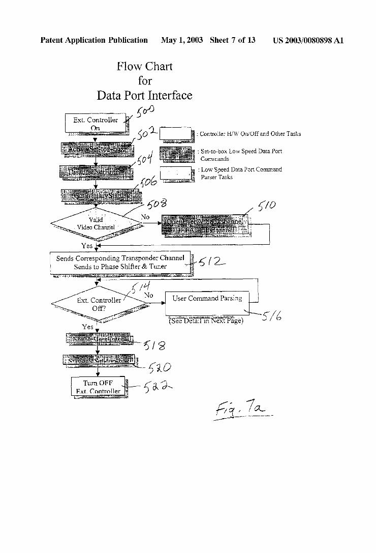
Flow Chart for
Data Port Interface
: Controller H/W On/Off and Other Tasks
I Set—to-box Low Speed Data Port Commands
1 Low Speed Data Port Command Parser Tasks
Yes ‘
Sends Corresponding Transponder Channel g l 2, Sends to Phase Shifter & Tuner * 1
User Command Parsing
fg',7ac
Patent Application Publication May 1, 2003 Sheet 8 of 13 US 2003/0080898 Al
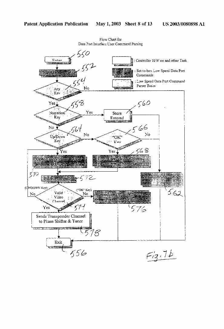
F low Chart for Data Port Interface User Command Parsing
i: a: ‘. : Controller H/W on and other Task
' : Set-to-box Low Speed Data Port
Commands
: Low Speed Data Port Command Parser Tasks
7‘ Valid‘ ivideo (‘l-mnnslz
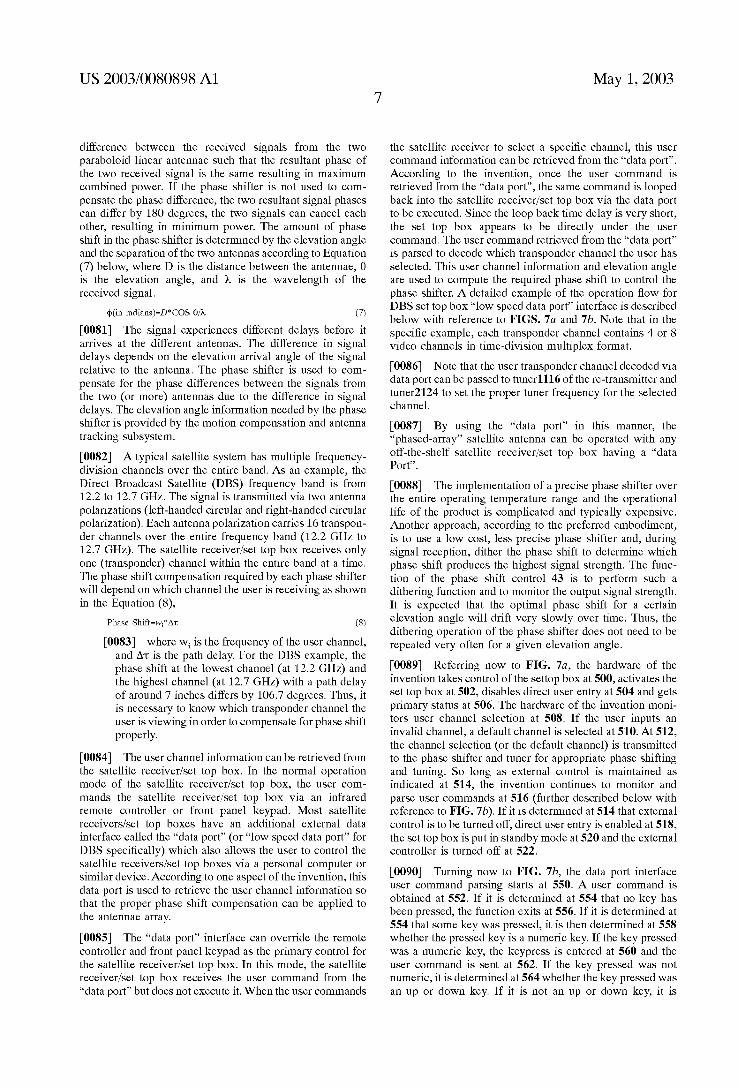
Sends Transponder Channel to Phase Shifter & Tuner
Patent Application Publication May 1, 2003 Sheet 9 0f 13 US 2003/0080898 A1
-1 im\\\\
9 @3252 :EC EOE
nwék
Patent Application Publication May 1, 2003 Sheet 10 0f 13 US 2003/0080898 A1
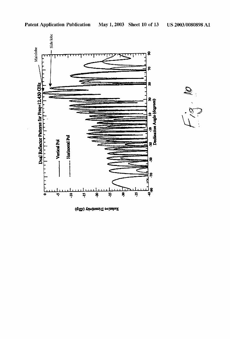
-— Side lobe
Mainiobe IIIIIITI'IFIIIIIITITY1II’.’ III‘IYTTa ,¢~' (‘Tb F
30
I .5 10
I
~10 ‘ Declination Anglo (dam) % mummmrm'mumcnz lllill|TITIIITIIIYI'III|I VaticalPol Horizontal“ I‘ -so
"u..." A - 4 1 <1‘ llLlIllllllllll'lllillllllLlli1 lllLL 8
(dam We: am
Patent Application Publication May 1, 2003 Sheet 11 0f13
/
POW€L M518!‘ ___> 1225GHZ~ 5.25~5.35GHZ \ T 310
12.75GH2 ‘
y BPF Another__’ Combine:
' Channel '3“ 9‘0 Power
Ampli?er 1*} (pl (9 / 0 x2 / 1
1‘ +2 ; SYNTHESIZER
n M
/
VCQ : OSC d/l‘j J L FILTEFIK Tuner 1
‘l 0 4 L N ‘7
A
M04
US 2003/0080898 A1
5.25~5-35GHZ 950M~L45GH1 I
\ H0 252% ‘bl
of} UM 7K? 7> 0 x2 / 1/ 1* I} “ +2 ; SYNTHESIZER
99% vco = LOOP osc
FILTER \
I
L an» “'3
Patent Application Publication May 1, 2003 Sheet 12 0f 13 US 2003/0080898 A1
m.,\ W 470% /
HHHH
898 A1 Patent Application Publication May 1, 2003 Sheet 13 0f 13 US 2003/0080
‘ Radomc Trail of Luggage
Rack Lock f h _ 6 Lock Trail of Luggage
3 l ’ / Rack
2o 0
3,10
PM? , /§/' ~~_1<-,»-_-_\
Power-On Radome Position P P H
J_ )/ " °w¢r a ome osmon f" U Car Roof ,
Pump Antenna Position Hg?gxhc During Power~0ff p
, /6
US 2003/0080898 A1
EASY SET-UP, LOW PROFILE, VEHICLE MOUNTED, IN-MOTION TRACKING, SATELLITE
ANTENNA
BACKGROUND OF THE INVENTION
[0001] 1. Field of the Invention
[0002] The invention relates to vehicle mounted satellite antennae. More particularly, the invention relates to a vehicle mounted satellite antenna Which is easy to install, has a loW pro?le, and Which is operable While the vehicle is in motion.
[0003] 2. State of the Art
[0004] It has long been knoWn to mount a satellite antenna (dish) atop a vehicle for purposes of communicating With a geostationary or other type of satellite. The initial applica tions for mounting a satellite dish on a vehicle Were military communication and remote television neWs broadcasting. Consequently, the ?rst methods of mounting a satellite dish included a telescoping mast Which Was hingedly coupled to the vehicle. When the vehicle Was in motion, the mast Would be retracted and folded With the satellite dish lying end up on the roof or a side Wall of the vehicle. The dish Would be deployed only When the vehicle Was stationary. Such a deployable vehicle mounted satellite dish is disclosed in US. Pat. No. 5,961,092 to Cof?eld. Until recently, no vehicle mounted satellite antennae Were operable While the vehicle Was in motion. The relatively large siZe of a con ventional satellite dish antenna presents signi?cant Wind resistance if deployed on a vehicle in motion. This Wind resistance adversely affects the operation of the vehicle and subjects the satellite dish to potential Wind damage. More over, satellite dishes must be accurately aimed at a satellite Within a relatively narroW aperture or “look WindoW”. In order to operate a satellite dish mounted on a vehicle in motion, it Would be necessary to constantly re-aim the dish in order to maintain communication With the satellite.
[0005] Recently, satellite antennae have been developed Which may be deployed on a vehicle and operated While the vehicle is in motion. Such antennae are disclosed in US. Pat. No. 5,398,035 to Densmore et al., US. Pat. No. 5,982,333 to Stillinger, and US. Pat. No. 6,049,306 to Amarillas. These antenna systems generally include a satellite antenna of reduced siZe and a solenoid system for aiming the antenna. The solenoid system is coupled to a feedback system and/or vehicle motion detectors in order to automati cally re-aim the antenna as the vehicle is in motion. In order to reduce aerodynamic drag and protect the antenna from Wind damage, an aerodynamic radome is often used to cover the antenna.
[0006] Vehicle mounted satellite antennae Which are oper able While the vehicle is in motion, can provide one-Way or tWo-Way satellite communications. Some applications for such antennae include satellite television reception, tele phony in remote locations Where cellular telephone service is unavailable, and broadband data communications. The application of television reception may be advantageously applied in common carrier transportation such as long distance buses, in recreational vehicles including boats, and in the rear seats of family mini-vans. The application of remote telephony may be applied in the same situations as Well as in various other governmental and commercial
May 1, 2003
settings. The application of broadband data communication may also be applied in many personal, commercial, and governmental settings. [0007] Broadband satellite communication, such as tele vision reception or broadband data communication, requires a high gain antenna With high cross-polariZation isolation and loW signal sidelobes. Satellite antenna gain is propor tional to the aperture area of the re?ector. Stationary satellite antennae typically utiliZe a circular parabolic re?ector. Sat ellite antennae designed for use on a moving vehicle have a loW pro?le. In order to maintain gain, these loW pro?le antenna are short but Wide so that the overall aperture area is kept high. HoWever, this design strategy only Works to a point. When the Width to height ratio eXceeds a certain value such as 2, the efficiency of the antenna is adversely affected. The presently available vehicle mountable satellite antenna for commercial and personal use are no shorter than approxi mately ?fteen inches in height.
[0008] In addition to the issue of providing loW pro?le tracking antennae, the process of installing a satellite antenna on a vehicle is not trivial. Holes must be drilled through the roof (or body panel) of the vehicle; coaXial cable must be routed from the antenna to a receiver or transceiver; and poWer cables must be routed to the antenna’s tracking system. The installation process is therefore time consuming and costly.
SUMMARY OF THE INVENTION
[0009] It is therefore an object of the invention to provide a vehicle mountable satellite antenna.
[0010] It is also an object of the invention to provide a vehicle mounted satellite antenna Which is operable While the vehicle is in motion.
[0011] It is another object of the invention to provide a vehicle mounted satellite antenna Which has a loW pro?le.
[0012] It is also an object of the invention to provide a vehicle mounted satellite antenna Which has high gain.
[0013] It is another object of the invention to provide a vehicle mounted satellite antenna Which has high ef?ciency.
[0014] It is still another object of the invention to provide a vehicle mountable satellite antenna Which is easy to install.
[0015] In accord With these objects Which Will be dis cussed in detail beloW, the satellite antenna of the present invention includes tWo loW pro?le paraboloid linear re?ector antenna assemblies mounted on a rotatable platform Which is rotatably coupled to a base plate. Each antenna assembly is provided With tWo sub-re?ectors With a plastic matching element betWeen them. The tWo antenna assemblies are mounted parallel to each other and are pivotable relative to the rotatable platform. A ?rst servo motor is coupled to the rotatable platform for aZimuth tracking. A second servo motor is coupled by a rigid arm to both antenna assemblies for elevation tracking. The tWo antennae assemblies are each provided With a line feed for receiving a polariZed satellite signal. A number of slot antenna probes are located in the back of each antenna assembly. The signal is coupled from the slot antenna into a microWave PCB or Waveguide in the back of each antenna. The antenna probes are attached to a microWave circuit board, Where tWo orthogonal linearly polariZed signals are extracted. The tWo linearly polariZed
US 2003/0080898 A1
signals are fed into a 90° hybrid and tWo circularly polarized signals are extracted. The signals of the same circular polarization from the same antenna assembly are ampli?ed and combined into a single signal in a beam forming netWork (BFN) circuit on the microWave PCB.
[0016] In order to correct for time delay difference in the signals received by the tWo antenna assemblies, a phase shifter is employed to correct for the phase shift for the signal received from one antenna before it is combined With the other antenna. Aunique feature of this antenna design is that only one phase shifter is required, thereby achieving a very loW cost design as compared to the conventional phased array antenna implementation Which typically requires a large number of phase shifters.
[0017] According to an alternate embodiment, the back side of each antenna dish is provided With a rectangular Wave guide structure With a step tooth polariZer stud in the middle of the Wave guide. The polariZer stud Within the rectangular Wave guide converts the signal from linear polariZation to circular polariZation. Each antenna contains tWo roWs of multiple antenna feeds distributed over the entire length of the antenna. The upper roW of antenna feeds extracts a (left or right) circularly polariZed signal and the loWer roW of antenna feeds extracts a (right or left) circularly polariZed signal. Each roW of antenna feeds is connected via a circuit board or Wave guide to a beam forming netWork (BFN) Where signals are ampli?ed and combined into a single signal. The output of one of the BFNs is connected to the input of a phase shifter via a ?exible coaxial cable. The output of the other BFN is connected to either an attenuator or an ampli?er (depending on Whether the phase shifter ampli?es or attenuates the other signal) and then to one input port of a tWo-to-one combiner via a ?exible coaxial cable. The output of the phase shifter is connected to the other input port of the combiner. The ampli?er or attenuator is used to amplify or attenuate the signal by the same amount as the gain or loss of the phase shifter so that the poWer of the signals from both BFN’s are equal before they are combined.
[0018] Dividing the antenna physical aperture into tWo or more paraboloid linear dishes reduces the overall height of the antenna array by half. Providing each cylindrical dish With multiple feeds instead of single feed maintains the overall antenna ef?ciency.
[0019] The combined signal from the tWo paraboloid linear antennae is routed through a rotary joint, Which routes the received signal to circuits located under the rotatable platform but above the base plate. According to the preferred embodiment of the invention, the circuits betWeen the rotat able platform and the base plate include a re-transmitter for transmitting received satellite signals (at a longer Wave length) to a ?rst receiver inside the vehicle. A second receiver is also preferably provided on the base plate. According to one embodiment of the invention, the second receiver is used to receive channel selection signals and other control signals transmitted by a transmitter inside the vehicle. According to another embodiment, a transceiver is used at the base plate to provide tWo-Way Wireless commu nication With equipment, such as telephones and computers, through another transceiver inside the vehicle.
[0020] The use of the re-transmitter and second receiver betWeen the rotatable platform and the base plate eliminates
May 1, 2003
the need for signal Wiring betWeen the antennae assembly and the interior of the vehicle. According to a preferred embodiment of the invention, an independent poWer supply is also provided betWeen the rotatable platform and the base plate to eliminate the need for poWer Wiring betWeen the antennae assembly and the interior of the vehicle. According to one preferred embodiment, the independent poWer supply includes a storage device such as a battery or a coil and a charging device such as a Wind poWered generator. A solar cell array may also be used as a charging device.
[0021] According to other aspects of the invention, elec tronic dithering systems are used to track a satellite quickly While a vehicle is in motion. Methods are also provided for adjusting the bias of motion sensors via the use of longitu dinal and lateral accelerometers. Methods are also provided for receiving either circularly polariZed or linearly polariZed signals. According to one embodiment of the invention, the “data port” of a conventional satellite receiver settop box is used determine the appropriate phase shift in the antennae array for a selected channel.
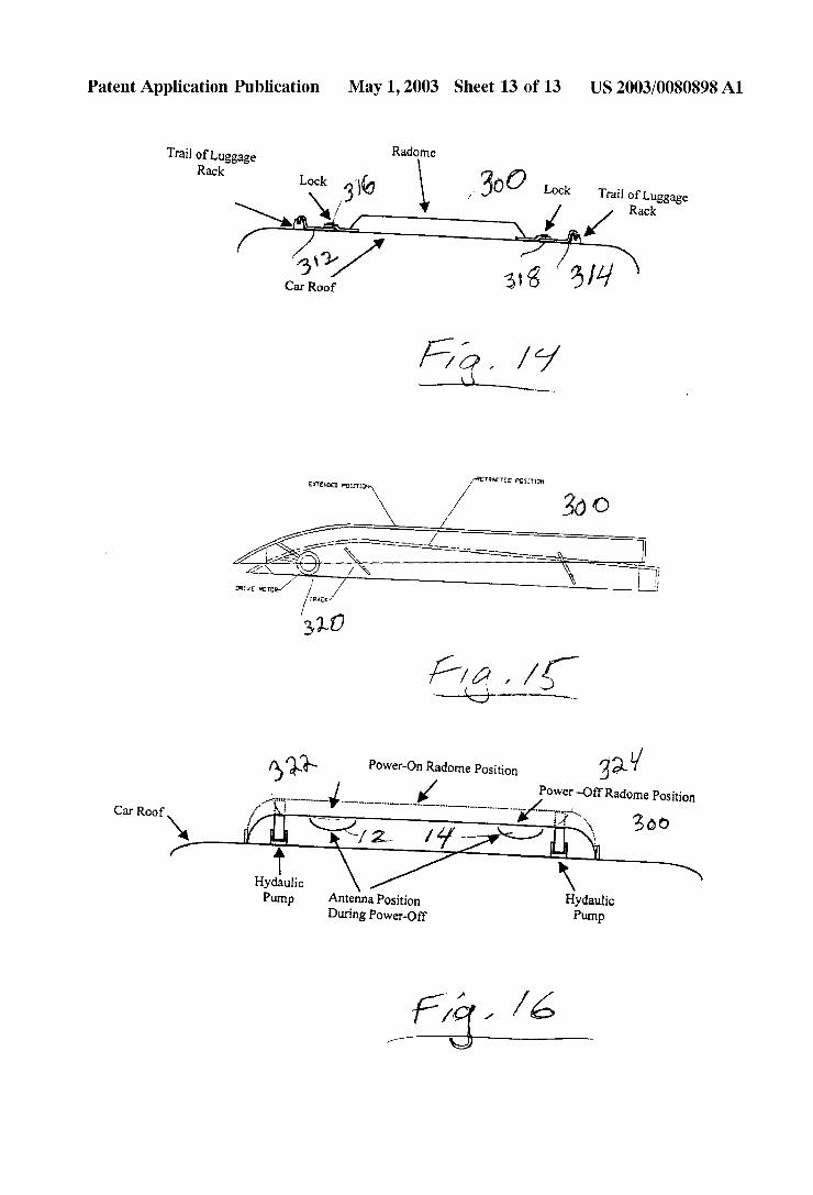
[0022] According to another aspect of the invention, the antenna system is provided With a retractable radome. When the antenna is not in use, the tWo cylindrical dishes are aimed straight up, decreasing the overall height of the system, and the radome is retracted.
[0023] Additional objects and advantages of the invention Will become apparent to those skilled in the art upon reference to the detailed description taken in conjunction With the provided ?gures.
BRIEF DESCRIPTION OF THE DRAWINGS
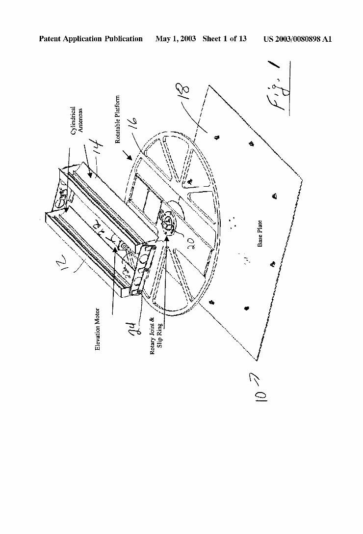
[0024] FIG. 1 is an exploded perspective vieW illustrating some of the major components of the invention;
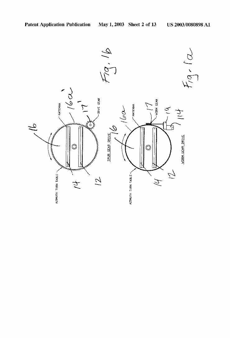
[0025] FIG. 1a ia a plan vieW of one embodiment of an aZimuth turntable drive;
[0026] FIG. 1b is a plan vieW of an alternate embodiment of an aZimuth turntable drive;
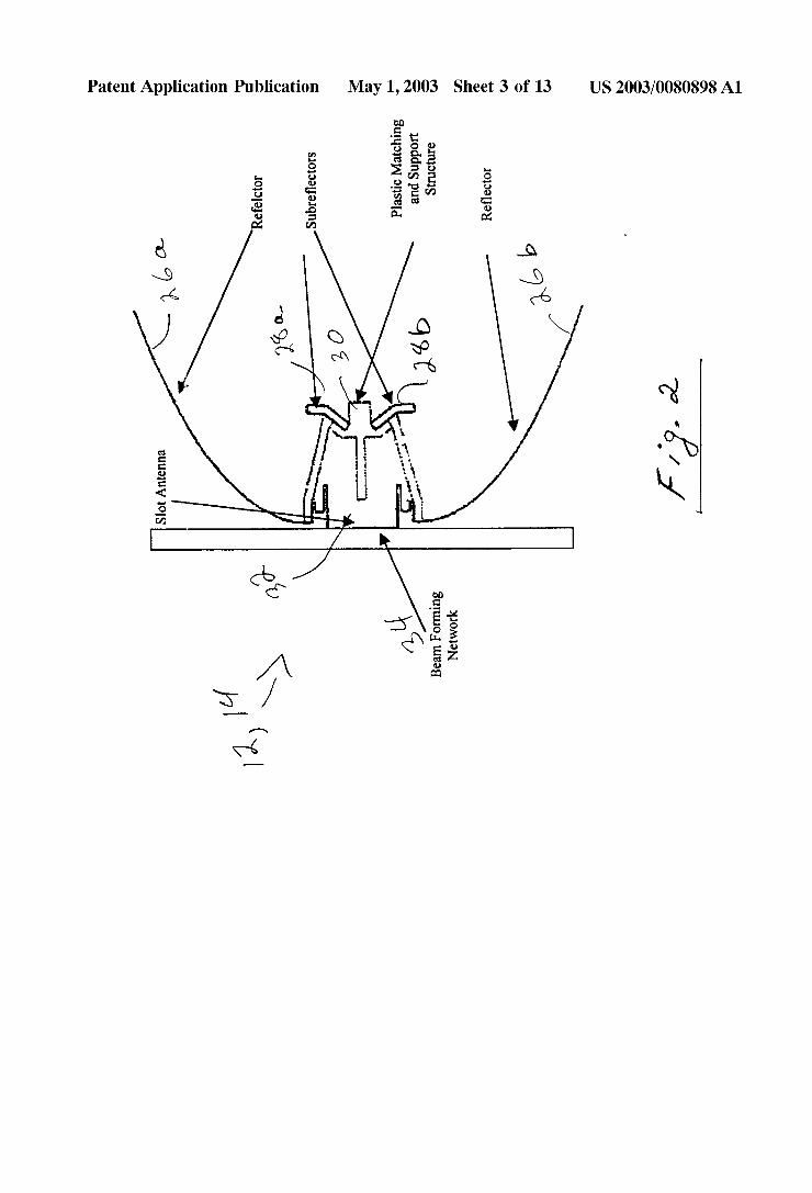
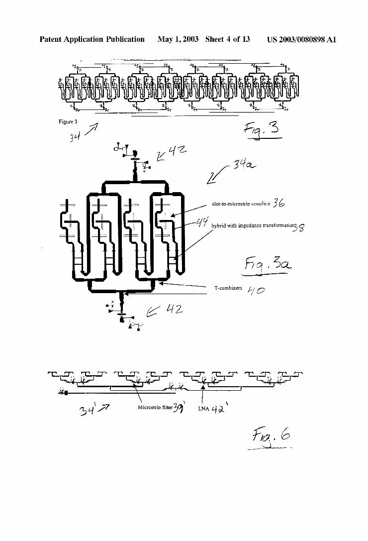
[0027] FIG. 2 is a schematic side elevation vieW illustrat ing the relative placement of re?ectors and beam forming netWork; [0028] FIG. 3 is a schematic vieW of a thirty-tWo element beam forming netWork;
[0029] FIG. 3a is an enlarged vieW of a portion of FIG. 3 illustrating hoW four signals are combined before feeding the combined signals to a loW noise ampli?er;
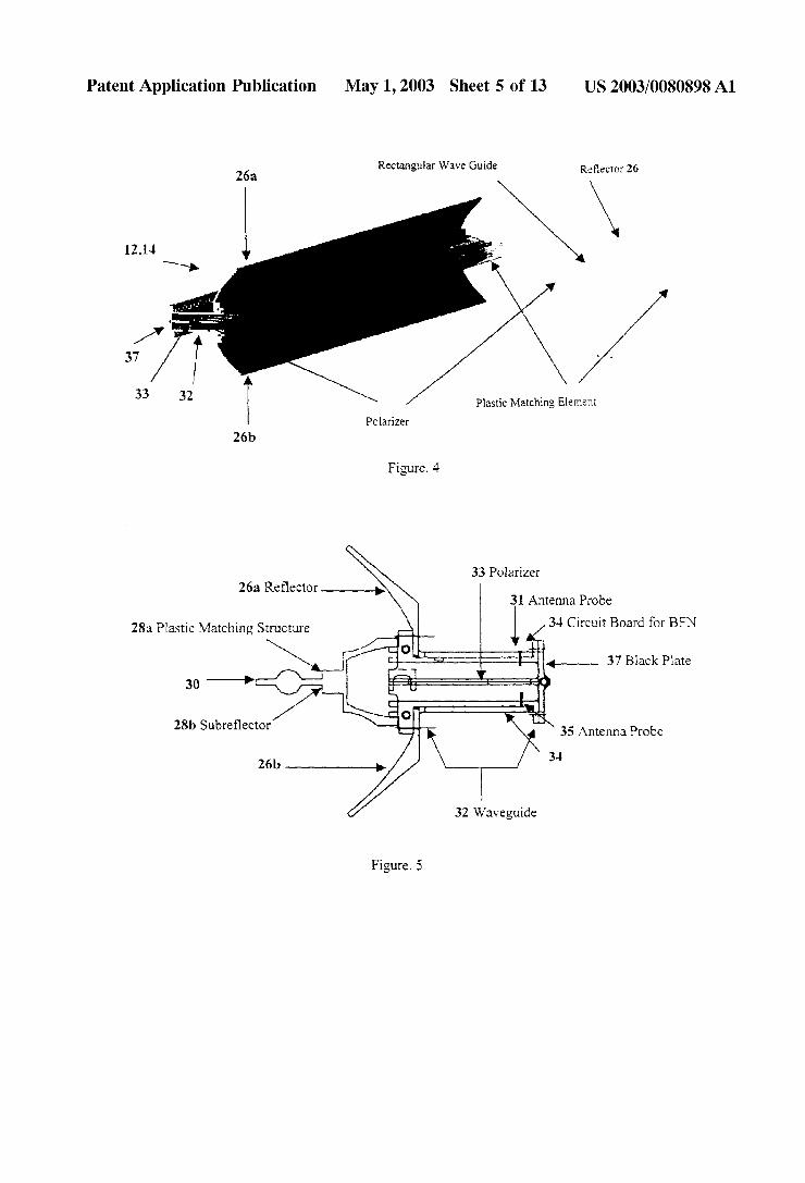
[0030] FIG. 4 is a perspective vieW of an alternate embodiment of an antenna assembly according to the inven tion; [0031] FIG. 5 is a schematic side elevation vieW of a portion of the assembly of FIG. 4;
[0032] FIG. 6 illustrates an alternate embodiment of a beam forming netWork utiliZed With the antenna embodi ment of FIGS. 4 and 5;
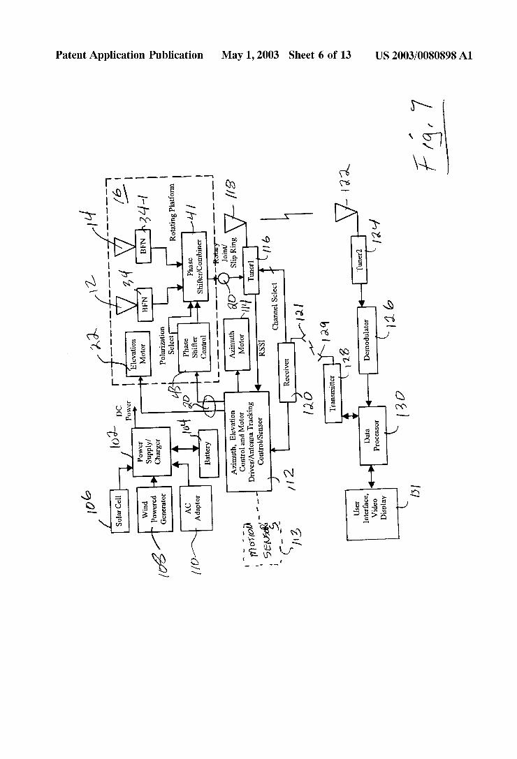
[0033] FIG. 7 is a simpli?ed schematic diagram of a Wireless retransmission system according to the invention;
[0034] FIGS. 7a and 7b illustrate methods of the inven tion for determining appropriate phase shift for a selected channel;
US 2003/0080898 A1
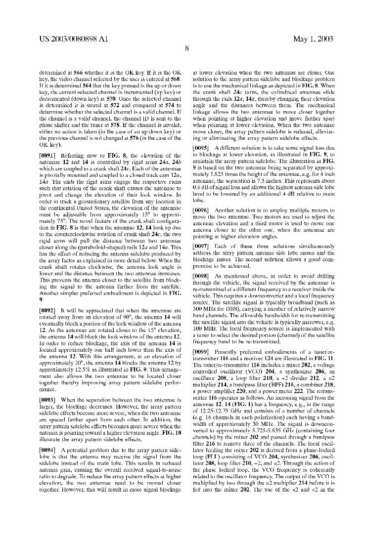
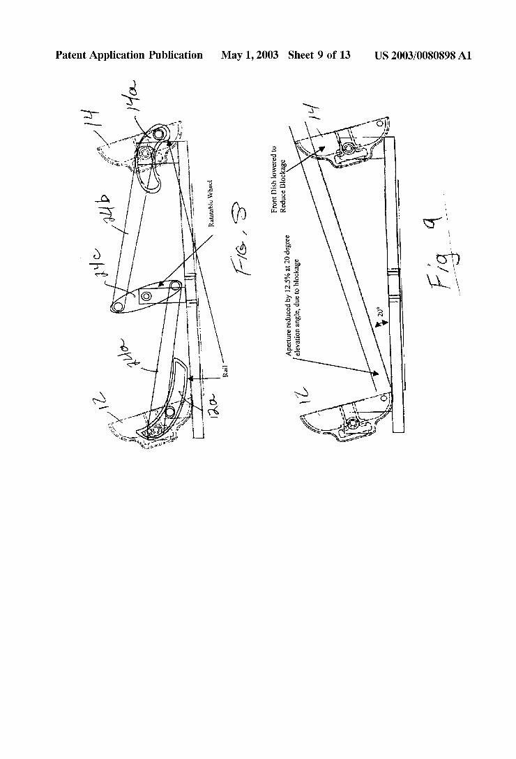
[0035] FIG. 8 is a schematic side elevation vieW of mechanical linkage coupling the tWo antennae for elevation tracking; [0036] FIG. 9 is a vieW similar to FIG. 8 illustrating relative location of the antennae to minimiZe blockage;
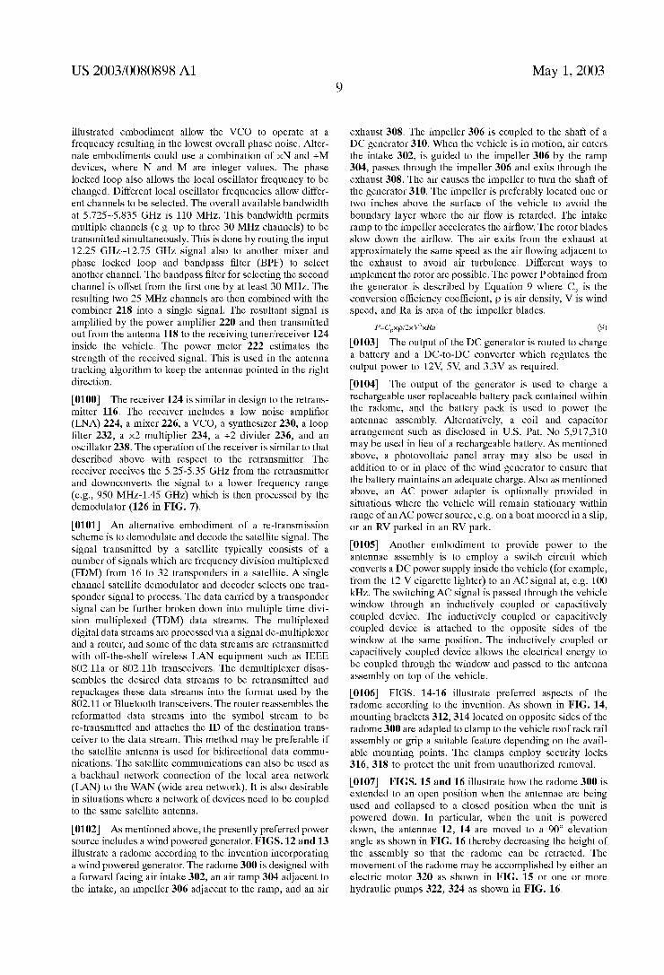
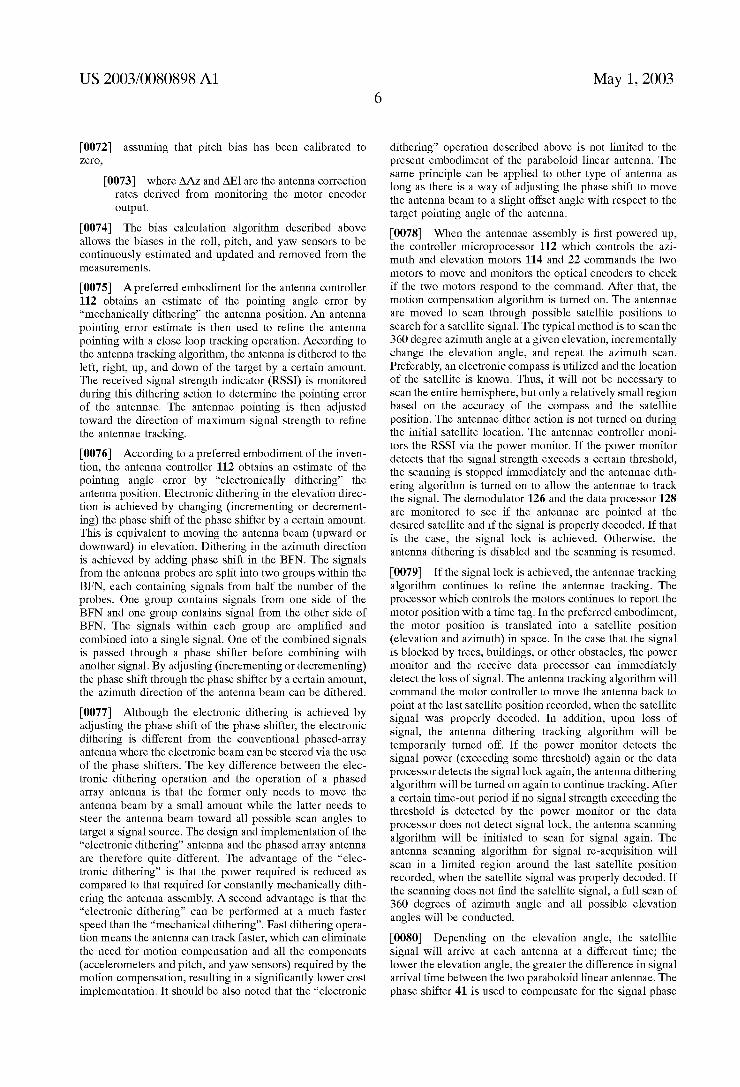
[0037] FIG. 10 is a graph of array pattern side lobe effects;
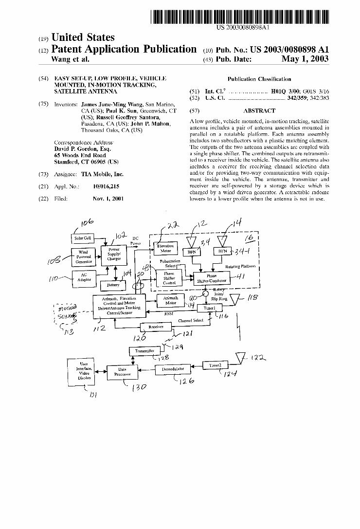
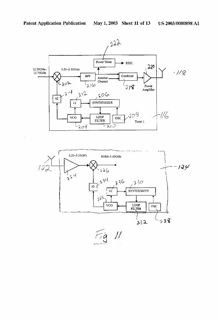
[0038] FIG. 11 is a simpli?ed schematic diagram of a presently preferred embodiment of the tWo tuners of FIG. 5;
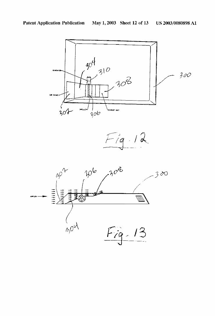
[0039] FIG. 12 is a plan vieW of a radome With a Wind poWered generator according to the invention;
[0040] FIG. 13 is a partially cut aWay side elevation vieW of a radome With a Wind poWered generator according to the invention; [0041] FIG. 14 is a schematic side elevation vieW illus trating the antennae system of the invention mounted to the roof of a vehicle;
[0042] FIG. 15 is a schematic side elevation vieW illus trating tWo positions of the retractable radome of the inven tion; and
[0043] FIG. 16 is a schematic side elevation vieW illus trating tWo positions of the retractable radome of the inven tion With the antennae aimed straight up.
DETAILED DESCRIPTION OF THE PREFERRED EMBODIMENTS
[0044] Referring noW to FIGS. 1 and 2, the satellite antenna 10 of the present invention includes tWo loW pro?le paraboloid linear re?ector antenna assemblies 12, 14 mounted on a rotatable platform (turntable) 16 Which is rotatably coupled to a base plate 18 via a rotary joint and slip ring 20. The rotary joint is an off-the-shelf product Which permits a high frequency signal to be conducted through a rotary joint. The slip ring consists of a number of circular traces on a circuit board and a corresponding number of “brushes” Which contact the circular traces. The slip ring is used to conduct loW frequency signals. The tWo antennae are mounted parallel to each other and are pivotable relative to the rotatable platform. A ?rst servo motor (shoWn schemati cally in FIG. 7 as 114) is coupled to the rotatable platform for aZimuth tracking. A second servo motor 22 (FIG. 1) is coupled by a rigid arm 24 (also shoWn in more detail in FIG. 8) to both antenna assemblies for elevation tracking.
[0045] As shoWn in FIG. 1a, the presently preferred construction of the rotatable platform 16 contains a gear 16a Which meshes on its circumference With a Worm gear 17 ?Xedly mounted on a shaft, Which is coupled through a gear boX 19 to the rotary shaft of an aZimuth drive motor 114. A rotary optical encoder (not shoWn) is coupled to the rotary shaft of the aZimuth drive motor 114. The aZimuth drive motor is ?Xedly mounted on the stationary base plate (18 in FIG. 1), and hence When it is energiZed for rotation in the forWard or reverse direction, it turns the rotatable platform clockWise or counter-clockWise as vieWed from the top, thus pointing the antennae to the left or right in the aZimuth direction. The optical encoder delivers pulses corresponding to the amount of rotation in aZimuth direction. The number of pulses is counted Which alloWs a microprocessor Which controls the aZimuth movement of the rotatable platform to knoW the eXact amount of platform movement in the aZi
May 1, 2003
muth direction. A magnet (not shoWn) mounted on the rotatable platform and a Hall effect sensor (not shoWn) ?Xedly mounted to the stationary base plate delivers a pulse to the microprocessor When the platform reaches a “Home” position.
[0046] An alternative embodiment is shoWn in FIG. 1b Where a spur gear 17‘ engages teeth 16a’on the perimeter of the turntable 16. The Worm gear arrangement of FIG. 1a is preferred because it Will inherently lock the turntable in position When the motor is stopped. If the spur gear embodi ment of FIG. 1b is used, it is desirable to electrically shunt the motor When it is not running to thereby lock the turntable in position.
[0047] As shoWn in FIG. 1, the antennae 12, 14 are mechanically linked to a rotary shaft 22a. The rotary shaft 22a ?Xedly carries a gear (not shoWn) Which meshes With a gear (not shoWn) ?Xedly mounted on the output shaft (not shoWn) of a gear boX (not shoWn). The gear boX includes an input shaft (not shoWn) Which is engaged by the rotary shaft (not shoWn) of an elevation motor drive 22. Arotary encoder (not shoWn) is coupled to the rotary shaft of the motor. The elevation drive motor 22 is ?Xedly mounted on a support bracket on the rotatable platform 16. When the motor 22 is energiZed for rotation, it rotates the tWo antennae integrally in an upWard or doWnWard direction to point the antennae to the desired elevation angle. The rotary encoder delivers pulses corresponding to the amount of rotation in elevation direction. The number of pulses is counted Which alloWs the microprocessor (112 in FIG. 7) Which controls the elevation movement of the rotatable platform to knoW the eXact amount of platform movement in the elevation direction. A magnet (not shoWn) mounted on the antenna and a Hall effect sensor (not shoWn) ?Xedly mounted to the rotatable platform delivers a pulse to the microprocessor When the antennae reach a “Home” position. Alternatively, a mechani cal gimbal stopper and reed sWitch can be used to detect if the antenna reaches the gimbal limit.
[0048] As seen best in FIG. 2, according to a ?rst embodi ment, each antenna assembly 12, 14 includes a bifurcated main re?ector 26a, 26b Which focuses onto a pair of subre?ectors 28a, 28b Which are mounted on a plastic matching and support structure 30. The subre?ectors focus onto a slot antenna 32 Which is coupled to a beam forming netWork 34. In addition, signals from a satellite are free to pass betWeen the tWo subre?ectors. The dimensions of the antenna are such that the re?ected signals and the direct pass through signal have a phase difference of 360° Which makes them in phase With each other. This permits the signals to be constructively miXed thereby increasing the ef?ciency of the antenna as compared to a conventional Cassegrain antenna.
[0049] The tWo antennae 12, 14 are each provided With a line feed for receiving a polariZed satellite signal. In the preferred embodiment, slot antenna probes (FIG. 3 or 4) are located in the back of each antenna. The signal is coupled from the slot antenna into a microWave PCB or Waveguide in the back of each antenna. The antenna probes are attached to a circuit board (FIG. 3 or 4), Where tWo orthogonal linearly polariZed signals are both extracted from a circu larly polariZed satellite signal. The tWo linearly polariZed signals are fed into a 90° hybrid and tWo circularly polariZed signals are extracted. The signals of the same circular polariZation from the same antenna are ampli?ed and com
US 2003/0080898 A1
bined in the beam forming network 34. The antennae described herein can also be used to receive a linearly polarized satellite signal if the slot orientation is aligned With the polarization of the satellite signal.
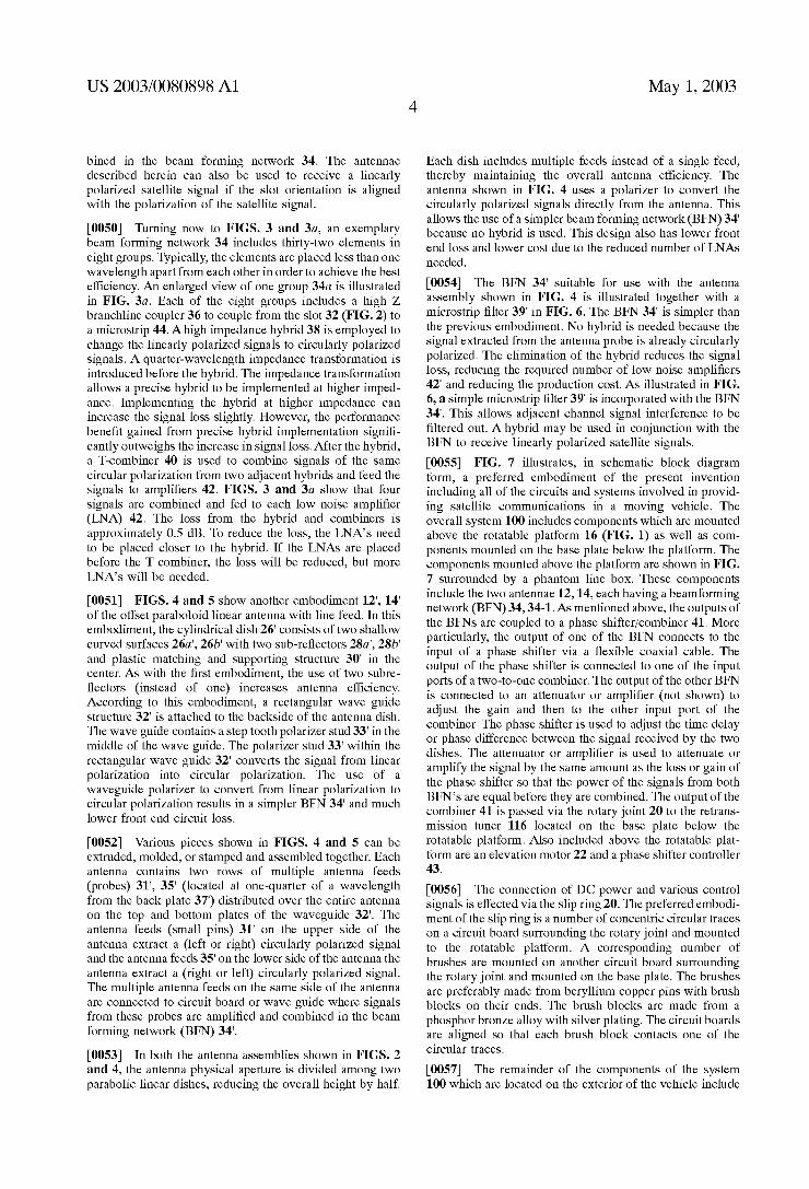
[0050] Turning noW to FIGS. 3 and 3a, an exemplary beam forming netWork 34 includes thirty-tWo elements in eight groups. Typically, the elements are placed less than one Wavelength apart from each other in order to achieve the best ef?ciency. An enlarged vieW of one group 34a is illustrated in FIG. 3a. Each of the eight groups includes a high Z branchline coupler 36 to couple from the slot 32 (FIG. 2) to a microstrip 44. Ahigh impedance hybrid 38 is employed to change the linearly polariZed signals to circularly polariZed signals. A quarter-Wavelength impedance transformation is introduced before the hybrid. The impedance transformation alloWs a precise hybrid to be implemented at higher imped ance. Implementing the hybrid at higher impedance can increase the signal loss slightly. HoWever, the performance bene?t gained from precise hybrid implementation signi? cantly outWeighs the increase in signal loss. After the hybrid, a T-combiner 40 is used to combine signals of the same circular polariZation from tWo adjacent hybrids and feed the signals to ampli?ers 42. FIGS. 3 and 3a shoW that four signals are combined and fed to each loW noise ampli?er (LNA) 42. The loss from the hybrid and combiners is approximately 0.5 dB. To reduce the loss, the LNA’s need to be placed closer to the hybrid. If the LNAs are placed before the T combiner, the loss Will be reduced, but more LNA’s Will be needed.
[0051] FIGS. 4 and 5 shoW another embodiment 12‘, 14‘ of the offset paraboloid linear antenna With line feed. In this embodiment, the cylindrical dish 26‘ consists of tWo shalloW curved surfaces 26a‘, 26b‘ With tWo sub-re?ectors 28a‘, 28b‘ and plastic matching and supporting structure 30‘ in the center. As With the ?rst embodiment, the use of tWo subre ?ectors (instead of one) increases antenna ef?ciency. According to this embodiment, a rectangular Wave guide structure 32‘ is attached to the backside of the antenna dish. The Wave guide contains a step tooth polariZer stud 33‘ in the middle of the Wave guide. The polariZer stud 33‘ Within the rectangular Wave guide 32‘ converts the signal from linear polariZation into circular polariZation. The use of a Waveguide polariZer to convert from linear polariZation to circular polariZation results in a simpler BEN 34‘ and much loWer front end circuit loss.
[0052] Various pieces shoWn in FIGS. 4 and 5 can be extruded, molded, or stamped and assembled together. Each antenna contains tWo roWs of multiple antenna feeds (probes) 31‘, 35‘ (located at one-quarter of a Wavelength from the back plate 37‘) distributed over the entire antenna on the top and bottom plates of the Waveguide 32‘. The antenna feeds (small pins) 31‘ on the upper side of the antenna extract a (left or right) circularly polariZed signal and the antenna feeds 35‘ on the loWer side of the antenna the antenna extract a (right or left) circularly polariZed signal. The multiple antenna feeds on the same side of the antenna are connected to circuit board or Wave guide Where signals from these probes are ampli?ed and combined in the beam forming netWork (BEN) 34‘.
[0053] In both the antenna assemblies shoWn in FIGS. 2 and 4, the antenna physical aperture is divided among tWo parabolic linear dishes, reducing the overall height by half.
May 1, 2003
Each dish includes multiple feeds instead of a single feed, thereby maintaining the overall antenna efficiency. The antenna shoWn in FIG. 4 uses a polariZer to convert the circularly polariZed signals directly from the antenna. This alloWs the use of a simpler beam forming netWork (BEN) 34‘ because no hybrid is used. This design also has loWer front end loss and loWer cost due to the reduced number of LNAs needed.
[0054] The BEN 34‘ suitable for use With the antenna assembly shoWn in FIG. 4 is illustrated together With a microstrip ?lter 39‘ in FIG. 6. The BEN 34‘ is simpler than the previous embodiment. No hybrid is needed because the signal extracted from the antenna probe is already circularly polariZed. The elimination of the hybrid reduces the signal loss, reducing the required number of loW noise ampli?ers 42‘ and reducing the production cost. As illustrated in FIG. 6, a simple microstrip ?lter 39‘ is incorporated With the BEN 34‘. This alloWs adjacent channel signal interference to be ?ltered out. A hybrid may be used in conjunction With the BFN to receive linearly polariZed satellite signals.
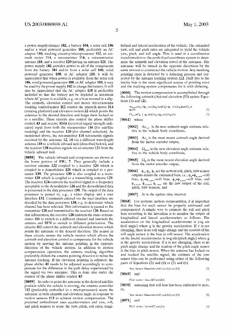
[0055] FIG. 7 illustrates, in schematic block diagram form, a preferred embodiment of the present invention including all of the circuits and systems involved in provid ing satellite communications in a moving vehicle. The overall system 100 includes components Which are mounted above the rotatable platform 16 (FIG. 1) as Well as com ponents mounted on the base plate beloW the platform. The components mounted above the platform are shoWn in FIG. 7 surrounded by a phantom line box. These components include the tWo antennae 12, 14, each having a beamforming netWork (BEN) 34, 34-1. As mentioned above, the outputs of the BFNs are coupled to a phase shifter/combiner 41. More particularly, the output of one of the BFN connects to the input of a phase shifter via a ?exible coaxial cable. The output of the phase shifter is connected to one of the input ports of a tWo-to-one combiner. The output of the other BFN is connected to an attenuator or ampli?er (not shoWn) to adjust the gain and then to the other input port of the combiner. The phase shifter is used to adjust the time delay or phase difference betWeen the signal received by the tWo dishes. The attenuator or ampli?er is used to attenuate or amplify the signal by the same amount as the loss or gain of the phase shifter so that the poWer of the signals from both BFN’s are equal before they are combined. The output of the combiner 41 is passed via the rotary joint 20 to the retrans mission tuner 116 located on the base plate beloW the rotatable platform. Also included above the rotatable plat form are an elevation motor 22 and a phase shifter controller 43.
[0056] The connection of DC poWer and various control signals is effected via the slip ring 20. The preferred embodi ment of the slip ring is a number of concentric circular traces on a circuit board surrounding the rotary joint and mounted to the rotatable platform. A corresponding number of brushes are mounted on another circuit board surrounding the rotary joint and mounted on the base plate. The brushes are preferably made from beryllium copper pins With brush blocks on their ends. The brush blocks are made from a phosphor bronZe alloy With silver plating. The circuit boards are aligned so that each brush block contacts one of the circular traces.
[0057] The remainder of the components of the system 100 Which are located on the exterior of the vehicle include
US 2003/0080898 A1
a power supply/charger 102, a battery 104, a solar cell 106 and/or a Wind powered generator 108, preferably an AC adaptor 110, tracking circuitry/microprocessor 112, an aZi muth motor 114, a retransmitter 116, a retransmission antenna 118, and a receiver 120 having an antenna 121. The poWer supply 102 provides poWer to all of the components from the battery 104 and/or from a solar cell 106, Wind poWered generator 108, or AC adaptor 110. It Will be appreciated that When poWer is available from the solar cell 106, Wind poWered generator 108, or AC adaptor 110, it may be used by the poWer supply 102 to charge the battery. It Will also be appreciated that the AC adapter 110 is preferably included so that the battery not be depleted in situations Where AC poWer is available, eg on a boat moored in a slip. The aZimuth, elevation control and motor driver/antenna tracking control/sensor 112 control the aZimuth motor 114 (rotating platform) and elevation motors 22 Which points the antennas to the desired direction and keeps them locked on to a satellite. These circuits also control the phase shifter control 43 and receive RSSI (received signal strength indi cator) input from both the retransmitter 116 (for satellite tracking) and the receiver 120 (for channel selection). As mentioned above, the retransmitter 116 retransmits signals received by the antennae 12, 14 via a different Wavelength antenna 118 to a vehicle inboard unit (described beloW), and the receiver 120 receives signals via an antenna 121 from the vehicle inboard unit.
[0058] The vehicle inboard unit components are shoWn at the loWer portion of FIG. 7. They generally include a receiver antenna 122 coupled to a receiver 124 Which is coupled to a demodulator 126 Which is coupled to a pro cessor 130. The processor 130 is also coupled to a trans mitter 128 Which is coupled to a transmitting antenna 129. The receiver 124 converts the received signal to a frequency acceptable to the demodulator 126 and the demodulated data is processed in the data processor 130. The output of the data processor is passed to, e.g., a video display and a user interface 131. Commands entered via the user interface are decoded by the data processor 130, eg to determine Which channel has been selected. This information is passed to the transmitter 128 and transmitted to the receiver 120. Based on that information, the receiver 120 instructs the tuner-retrans mitter 116 to sWitch to a different channel and instructs the antenna and BFN to sWitch to different polariZation. The circuits 112 control the aZimuth and elevation motors Which points the antennae to the desired direction. The sensor in these circuits senses the vehicle motion Which alloWs the aZimuth and elevation control to compensate for the vehicle motion by moving the antenna pointing in the opposite direction of the vehicle motion. In addition to motion compensation operation, the antenna tracking algorithm preferably dithers the antenna pointing direction to re?ne the antenna tracking. If the elevation pointing is adjusted, the phase shifter 41 needs to be adjusted accordingly to com pensate for the difference in the path delay experienced by the signal via tWo antennae. This is done also under the control of the phase shifter control 43.
[0059] In order to point the antennae at the desired satellite position While the vehicle is moving, the antenna controller 112 (preferably embodied in a microprocessor) steers the antennae in both aZimuth and elevation angle in response to motion sensors 113 to achieve motion compensation. The preferred embodiment uses accelerometers and yaW, roll, and pitch sensors to sense the yaW, pitch, roll rates, longi
May 1, 2003
tudinal and lateral acceleration of the vehicle. The estimated yaW, roll and pitch rates are integrated to yield the vehicle yaW, pitch, and roll angle. This is used in a coordination transformation to the earth-?xed coordinate system to deter mine the aZimuth and elevation travel of the antennae. The antennae Will be turned in the opposite directions by the same amount to counteract the vehicle motion. Any resulting pointing error is detected by a dithering process and cor rected by the antenna tracking system 112. Drift due to the inertia bias is the most signi?cant source of pointing error and the tracking system compensates for it With dithering.
[0060] The motion compensation is accomplished through the folloWing aZimuth and elevation (El) update Equa tions (1) and (2).
Elk+1=Elk-(-¢x SiHQAZQ'HPy COSQAZkDAI (2) [0061] Where
[0062] AZk+1 is the neW aZimuth angle estimate rela tive to the vehicle body coordinate,
[0063] AZk is the most recent aZimuth angle derived from the motor encoder output,
[0064] Elk+1 is the neW elevation angle estimate rela tive to the vehicle body coordinate,
[0065] Elk is the most recent elevation angle derived from the motor encoder output,
[0066] (PX, (by, (I)Z are the neWest roll, pitch, yaW sensor outputs minus the estimated bias, i.e., ¢X=¢X)mW—roll bias, ¢y=¢y)mw—roll bias, ¢z=¢z)mw—roll bias, and q>X>mW, 4km, (paw are the raW output of the roll, pitch, yaW sensors, and
[0067] At is the update time interval.
[0068] For accurate motion compensation, it is important that the bias for each sensor be properly estimated and compensated. A simple Way to estimate the roll and pitch bias according to the invention is to monitor the output of longitudinal and lateral accelerometers as folloWs. The acceleration on the longitudinal accelerometer is y=g sin (roll angle) Where g is the gravity acceleration. If y is not changing, there is no roll angle change and the readout of the roll angle sensor is the bias in roll sensor. The acceleration on the lateral accelerometer is X=g sin (pitch angle) Where g is the gravity acceleration. If X is not changing, there is no pitch angle change and the readout of the pitch angle sensor is the bias in pitch sensor. When the antenna has locked on and tracked the satellite signal, the estimate of the yaW sensor bias can be performed using either of the folloWing pairs of Equations (3) and (4) or (5) and
Yaw Sensor Bias=AAz+AEl tan(Az) tan(El) (3)
[0069] and Pitch sensor bias=AEl sec(Az) (4)
[0070] assuming that roll bias has been calibrated to Zero, or,
Yaw Sensor Bias=AAz+AEl cot(Az) tan(El) (5)
[0071] and Pitch sensor bias=AEl csc(Az) (6)
US 2003/0080898 A1
[0072] Zero,
assuming that pitch bias has been calibrated to
[0073] Where AAZ and AEl are the antenna correction rates derived from monitoring the motor encoder output.
[0074] The bias calculation algorithm described above alloWs the biases in the roll, pitch, and yaW sensors to be continuously estimated and updated and removed from the measurements.
[0075] Apreferred embodiment for the antenna controller 112 obtains an estimate of the pointing angle error by “mechanically dithering” the antenna position. An antenna pointing error estimate is then used to re?ne the antenna pointing With a close loop tracking operation. According to the antenna tracking algorithm, the antenna is dithered to the left, right, up, and doWn of the target by a certain amount. The received signal strength indicator (RSSI) is monitored during this dithering action to determine the pointing error of the antennae. The antennae pointing is then adjusted toWard the direction of maXimum signal strength to re?ne the antennae tracking.
[0076] According to a preferred embodiment of the inven tion, the antenna controller 112 obtains an estimate of the pointing angle error by “electronically dithering” the antenna position. Electronic dithering in the elevation direc tion is achieved by changing (incrementing or decrement ing) the phase shift of the phase shifter by a certain amount. This is equivalent to moving the antenna beam (upWard or doWnWard) in elevation. Dithering in the aZimuth direction is achieved by adding phase shift in the BFN. The signals from the antenna probes are split into tWo groups Within the BFN, each containing signals from half the number of the probes. One group contains signals from one side of the BFN and one group contains signal from the other side of BFN. The signals Within each group are ampli?ed and combined into a single signal. One of the combined signals is passed through a phase shifter before combining With another signal. By adjusting (incrementing or decrementing) the phase shift through the phase shifter by a certain amount, the aZimuth direction of the antenna beam can be dithered.
[0077] Although the electronic dithering is achieved by adjusting the phase shift of the phase shifter, the electronic dithering is different from the conventional phased-array antenna Where the electronic beam can be steered via the use of the phase shifters. The key difference betWeen the elec tronic dithering operation and the operation of a phased array antenna is that the former only needs to move the antenna beam by a small amount While the latter needs to steer the antenna beam toWard all possible scan angles to target a signal source. The design and implementation of the “electronic dithering” antenna and the phased array antenna are therefore quite different. The advantage of the “elec tronic dithering” is that the poWer required is reduced as compared to that required for constantly mechanically dith ering the antenna assembly. A second advantage is that the “electronic dithering” can be performed at a much faster speed than the “mechanical dithering”. Fast dithering opera tion means the antenna can track faster, Which can eliminate the need for motion compensation and all the components (accelerometers and pitch, and yaW sensors) required by the motion compensation, resulting in a signi?cantly loWer cost implementation. It should be also noted that the “electronic
May 1, 2003
dithering” operation described above is not limited to the present embodiment of the paraboloid linear antenna. The same principle can be applied to other type of antenna as long as there is a Way of adjusting the phase shift to move the antenna beam to a slight offset angle With respect to the target pointing angle of the antenna.
[0078] When the antennae assembly is ?rst poWered up, the controller microprocessor 112 Which controls the aZi muth and elevation motors 114 and 22 commands the tWo motors to move and monitors the optical encoders to check if the tWo motors respond to the command. After that, the motion compensation algorithm is turned on. The antennae are moved to scan through possible satellite positions to search for a satellite signal. The typical method is to scan the 360 degree aZimuth angle at a given elevation, incrementally change the elevation angle, and repeat the aZimuth scan. Preferably, an electronic compass is utiliZed and the location of the satellite is knoWn. Thus, it Will not be necessary to scan the entire hemisphere, but only a relatively small region based on the accuracy of the compass and the satellite position. The antennae dither action is not turned on during the initial satellite location. The antennae controller moni tors the RSSI via the poWer monitor. If the poWer monitor detects that the signal strength eXceeds a certain threshold, the scanning is stopped immediately and the antennae dith ering algorithm is turned on to alloW the antennae to track the signal. The demodulator 126 and the data processor 128 are monitored to see if the antennae are pointed at the desired satellite and if the signal is properly decoded. If that is the case, the signal lock is achieved. OtherWise, the antenna dithering is disabled and the scanning is resumed.
[0079] If the signal lock is achieved, the antennae tracking algorithm continues to re?ne the antennae tracking. The processor Which controls the motors continues to report the motor position With a time tag. In the preferred embodiment, the motor position is translated into a satellite position (elevation and aZimuth) in space. In the case that the signal is blocked by trees, buildings, or other obstacles, the poWer monitor and the receive data processor can immediately detect the loss of signal. The antenna tracking algorithm Will command the motor controller to move the antenna back to point at the last satellite position recorded, When the satellite signal Was properly decoded. In addition, upon loss of signal, the antenna dithering tracking algorithm Will be temporarily turned off. If the poWer monitor detects the signal poWer (exceeding some threshold) again or the data processor detects the signal lock again, the antenna dithering algorithm Will be turned on again to continue tracking. After a certain time-out period if no signal strength eXceeding the threshold is detected by the poWer monitor or the data processor does not detect signal lock, the antenna scanning algorithm Will be initiated to scan for signal again. The antenna scanning algorithm for signal re-acquisition Will scan in a limited region around the last satellite position recorded, When the satellite signal Was properly decoded. If the scanning does not ?nd the satellite signal, a full scan of 360 degrees of aZimuth angle and all possible elevation angles Will be conducted.
[0080] Depending on the elevation angle, the satellite signal Will arrive at each antenna at a different time; the loWer the elevation angle, the greater the difference in signal arrival time betWeen the tWo paraboloid linear antennae. The phase shifter 41 is used to compensate for the signal phase