Embed Size (px)
Citation preview
7/27/2019 Ec2021 Notes
http://slidepdf.com/reader/full/ec2021-notes 1/54
7/27/2019 Ec2021 Notes
http://slidepdf.com/reader/full/ec2021-notes 2/54
7/27/2019 Ec2021 Notes
http://slidepdf.com/reader/full/ec2021-notes 3/54
7/27/2019 Ec2021 Notes
http://slidepdf.com/reader/full/ec2021-notes 4/54
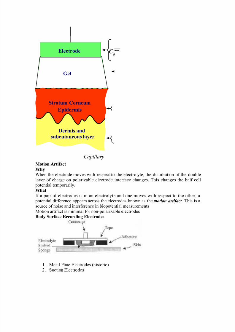
Motion rtifact
.$y
'hen the electrode moves with res&ect to the electrolyte, the distribution of the doublelayer of charge on &olarizable electrode interface changes. This changes the half cell &otential tem&orarily.
.$at
If a &air of electrodes is in an electrolyte and one moves with res&ect to the other, a &otential difference a&&ears across the electrodes /nown as the motion artifact. This is a
source of noise and interference in bio&otential measurements
1otion artifact is minimal for non!&olarizable electrodes
Body )urface &ecordin( Electrodes
2. 1etal late *lectrodes (historic"
3. uction *lectrodes
Electrode
Eider"is
/er"is andsu!cutaneous layer
C d
Gel
)tratu" Corneu"
Capillary
7/27/2019 Ec2021 Notes
http://slidepdf.com/reader/full/ec2021-notes 5/54
7/27/2019 Ec2021 Notes
http://slidepdf.com/reader/full/ec2021-notes 6/54
7/27/2019 Ec2021 Notes
http://slidepdf.com/reader/full/ec2021-notes 7/54
7/27/2019 Ec2021 Notes
http://slidepdf.com/reader/full/ec2021-notes 8/54
7/27/2019 Ec2021 Notes
http://slidepdf.com/reader/full/ec2021-notes 9/54
8!io
< %ny &otential or current at am&lifiers in&ut terminals can affect
8!io
< *lectric currents &roduced by the bio&otential am&lifier can result in microshoc/ and
macroshoc/ < The bioam&lifier must have isolation and &rotection circuitry so that the current through the
electrodes can be /e&t at safe levels and any artifact generated by such current can be minimized9utut I"edance 36out4
< The out&ut circuit does not &resent any critical &roblems, all it needs to do is to drive the load
< 9utut i"edance "ust !e lo# with res&ect to the load im&edance and it must be ca&able of
satisfying the &ower reuirements of the load
Band#idt$ 3B.4
requency resonse reuirements
< The bio&otential am&lifier must be sensitive to im&ortant freuency com&onents of the biosignal
< ince bio&otentials are low level signals, it is im&ortant to limit bandwidth o&timize signal!to!
noise ratio
Gain 3G4
< 9io&otential am&lifiers have a gain of 1000 or greater
Mode of 9eration< ?ery freuently biosignals are obtained from bi&olar electrodes
< *lectrodes sy""etrically located #it$ resect to (round need differential am&lification
< -igh CM&& reuired because:
2. Common mode signals much greater than the biosignal a&&ear on bi&olar electrodes
3. ymmetry with res&ect to ground is not &erfect (mismatch between electrode im&edances" 5
Cali!ration )i(nal
< 1edical and clinical eui&ment reuire uic/ calibration < The gain of the bio&otential am&lifier
must be calibrated to &rovide us with an accurate indication of the signals am&litude
< ush button to a&&ly standard signal to the in&ut of the bio&otential am&lifier
< %dDustable gain switch carefully selects calibrated fixed gains (in micro&rocessor5based
systems, gain adDustment can beElectrocardio(ra$y
E % very widely used medical instrument, which is utilized to diagnose and monitor cardiac beat
abnormalities is the
electrocardio(ra$
E It measures the electrical activity of the heart (more &recisely bio&otential differences arising
from the electrical activity of myocardium". 'eve already tal/ed about the genesis of the
*C$ signal.
E The *C$ machine uses surface electrodes and high in&ut im&edance
E 7ifferential am&lifiers with good common mode reDection ratio to record the electrocardiogram
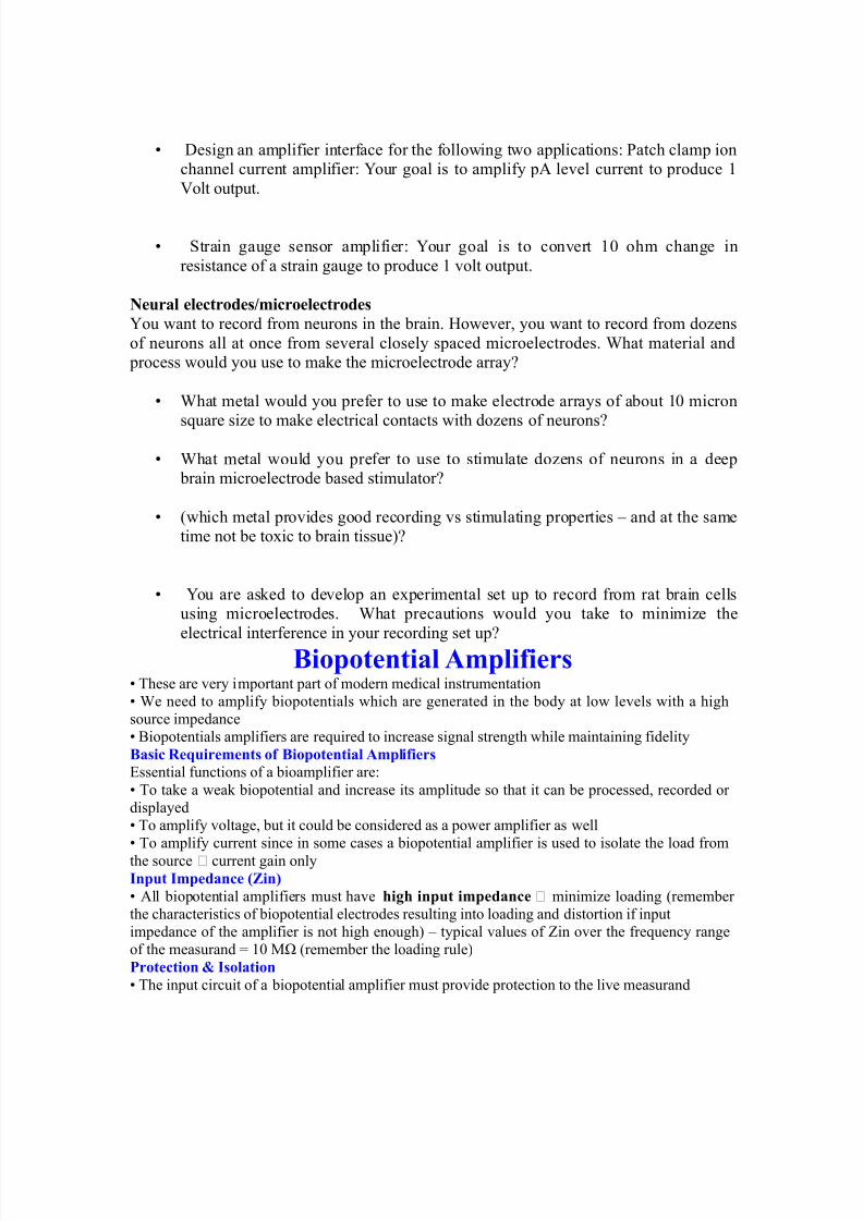
E )ormal *C$ am&litude ranges between +.F!= m?. )ormal freuency content of *C$ (for
diagnostic &ur&oses" is +.+F!2++ -z. % ty&ical *C$ waveform is shown below:
7/27/2019 Ec2021 Notes
http://slidepdf.com/reader/full/ec2021-notes 10/54
7/27/2019 Ec2021 Notes
http://slidepdf.com/reader/full/ec2021-notes 11/54
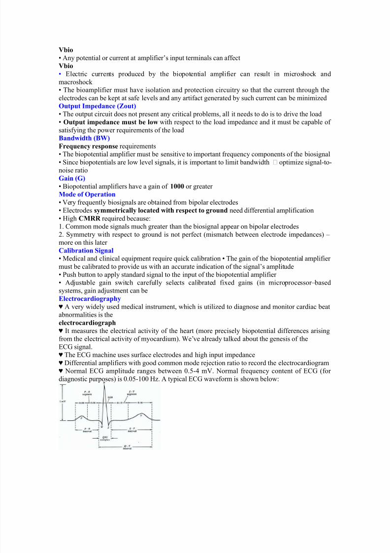
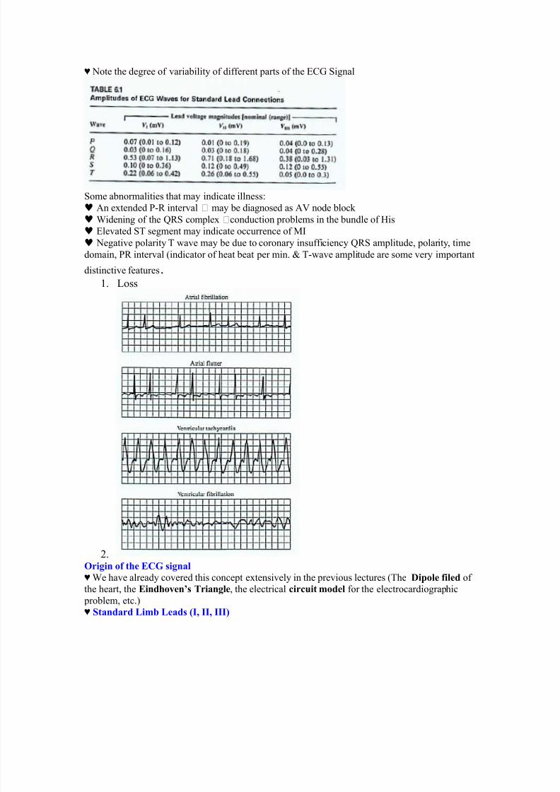
E )ote the degree of variability of different &arts of the *C$ ignal
ome abnormalities that may indicate illness:
♥ %n extended !# interval may be diagnosed as %? node bloc/
♥ 'idening of the G# com&lex conduction &roblems in the bundle of -is
♥ *levated T segment may indicate occurrence of 1I
♥ )egative &olarity T wave may be due to coronary insufficiency G# am&litude, &olarity, time
domain, # interval (indicator of heat beat &er min. H T!wave am&litude are some very im&ortant
distinctive features.2. oss
3.9ri(in of t$e ECG si(nal
E 'e have already covered this conce&t extensively in the &revious lectures (The /iole filed of
the heart, the Eind$o+en<s =rian(le, the electrical circuit "odel for the electrocardiogra&hic
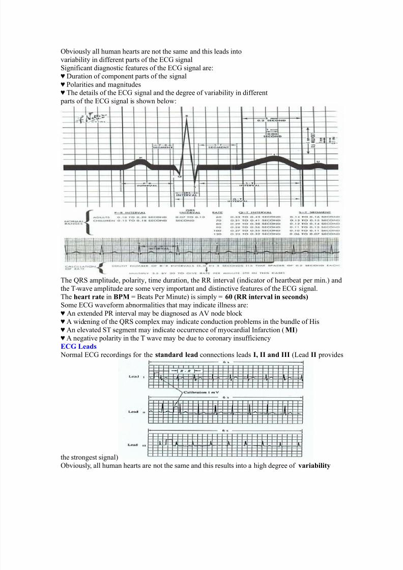
&roblem, etc."E )tandard Li"! Leads 3I; II; III4
7/27/2019 Ec2021 Notes
http://slidepdf.com/reader/full/ec2021-notes 12/54
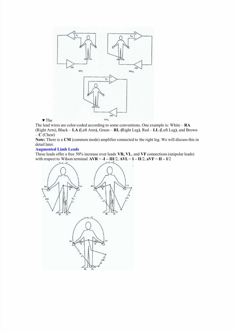
E The
The lead wires are color!coded according to some conventions. One exam&le is: 'hite 5 &
(#ight %rm", 9lac/ 5 L 3eft %rm4, $reen 5 &L 3#ight eg4, #ed 5 LL 3eft eg4, and 9rown
5 C (Chest"
Note' There is a CM (common mode" am&lifier connected to the right leg. 'e will discuss this in
detail later.
u("ented Li"! Leads
These leads offer a free F+ increase over leads 8&; 8L, and 8 connections (uni&olar leads"
with res&ect to 'ilson terminal 8& A -I – III03, 8L A I – II03, a8 A II – I03
7/27/2019 Ec2021 Notes
http://slidepdf.com/reader/full/ec2021-notes 13/54
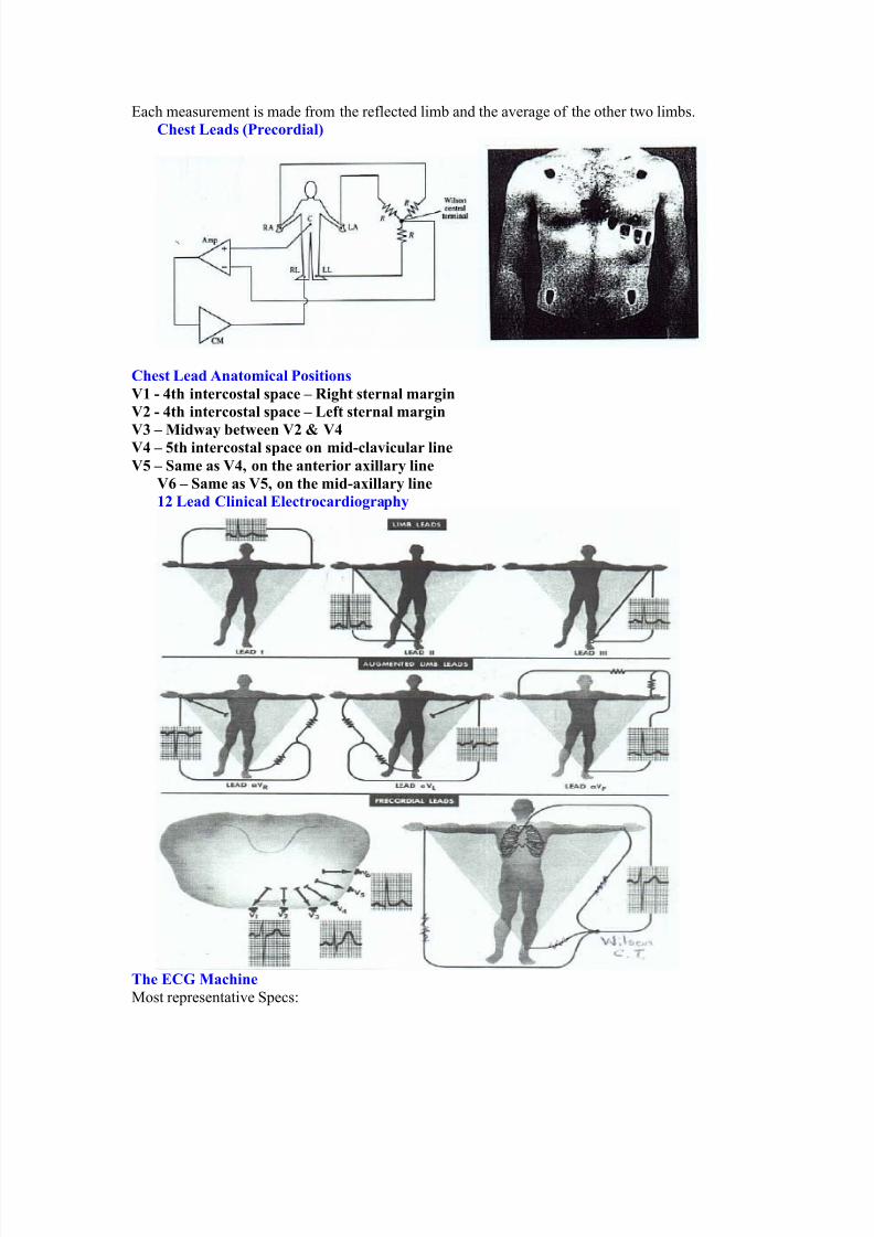
*ach measurement is made from the reflected limb and the average of the other two limbs.
C$est Leads 3Precordial4
C$est Lead nato"ical Positions
81 - >t$ intercostal sace – &i($t sternal "ar(in
82 - >t$ intercostal sace – Left sternal "ar(in
8? – Mid#ay !et#een 82 7 8>8> – @t$ intercostal sace on "id-cla+icular line
8@ – )a"e as 8>; on t$e anterior aillary line
8: – )a"e as 8@; on t$e "id-aillary line
12 Lead Clinical Electrocardio(ra$y
=$e ECG Mac$ine
1ost re&resentative &ecs:
7/27/2019 Ec2021 Notes
http://slidepdf.com/reader/full/ec2021-notes 14/54
< @in A 2+ 1B
< 4reuency res&onse A +.+F 52++ -z
< tri& Chart #ecorder &eed A 3F mm0sec.
< 4ast &eed A 2++ mm0sec.
4or detailed &ecs. #efer to the Table in your text Jummary of &erformance reuirements for electrocardiogra&hsK
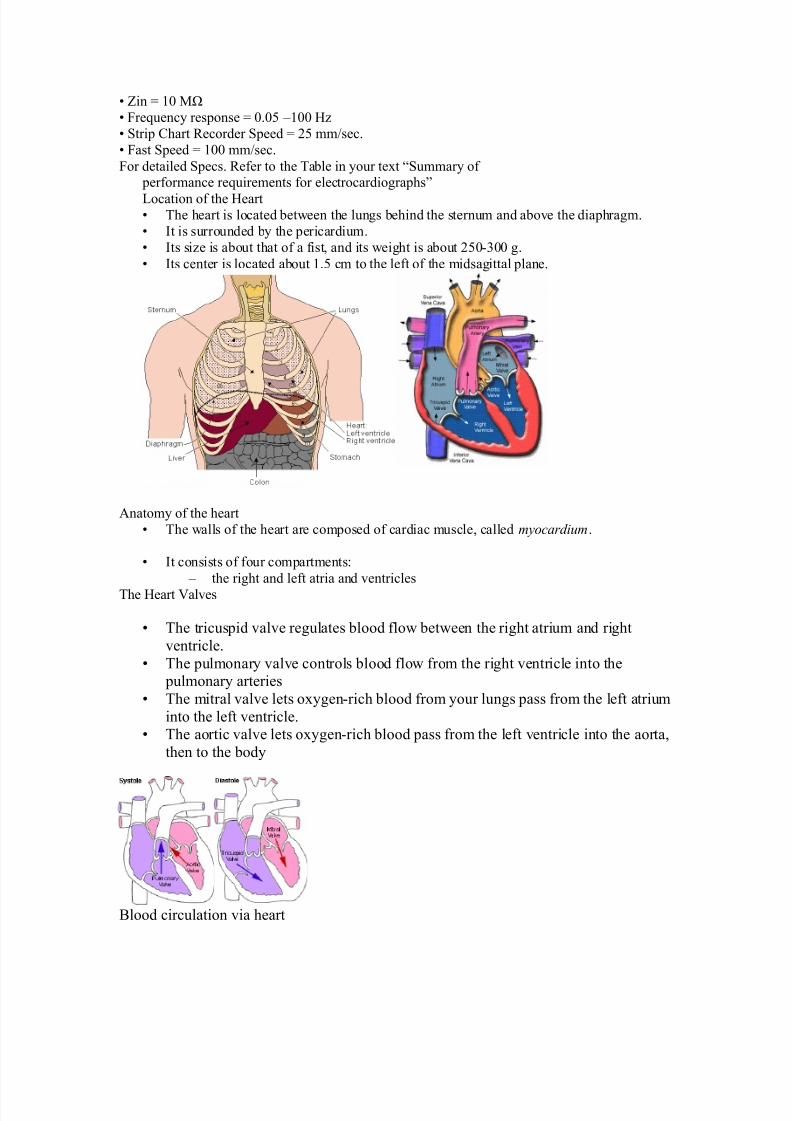
ocation of the -eart< The heart is located between the lungs behind the sternum and above the dia&hragm.
< It is surrounded by the &ericardium.
< Its size is about that of a fist, and its weight is about 3F+!++ g.
< Its center is located about 2.F cm to the left of the midsagittal &lane.
%natomy of the heart
< The walls of the heart are com&osed of cardiac muscle, called myocardium.
< It consists of four com&artments:
5 the right and left atria and ventricles
The -eart ?alves
< The tricus&id valve regulates blood flow between the right atrium and right
ventricle.
< The &ulmonary valve controls blood flow from the right ventricle into the &ulmonary arteries
< The mitral valve lets oxygen!rich blood from your lungs &ass from the left atrium
into the left ventricle.< The aortic valve lets oxygen!rich blood &ass from the left ventricle into the aorta,
then to the body
9lood circulation via heart
7/27/2019 Ec2021 Notes
http://slidepdf.com/reader/full/ec2021-notes 15/54
< The blood returns from the systemic circulation to the right atrium and from
there goes through the tricus&id valve to the right ventricle.
< It is eDected from the right ventricle through the &ulmonary valve to the lungs.
< Oxygenated blood returns from the lungs to the left atrium, and from therethrough the mitral valve to the left ventricle.
< 4inally blood is &um&ed through the aortic valve to the aorta and the systemiccirculation..
*lectrical activation of the heart
< In the heart muscle cell, or myocyte, electric activation ta/es &lace by means of
the same mechanism as in the nerve cell, i.e., from the inflow of )a ions acrossthe cell membrane.
< The am&litude of the action &otential is also similar, being 2++ m? for both nerve
and muscle
< The duration of the cardiac im&ulse is, however, two orders of magnitude longerthan in either nerve cell or sceletal muscle cell.
< %s in the nerve cell, re&olarization is a conseuence of the outflow of L ions.< The duration of the action im&ulse is about ++ ms
1echanical contraction of Cardiac 1uscle
< %ssociated with the electric activation of cardiac muscle cell is its mechanicalcontraction, which occurs a little later.
< %n im&ortant distinction between cardiac muscle tissue and s/eletal muscle is
that in cardiac muscle, activation can &ro&agate from one cell to anotherin any direction.
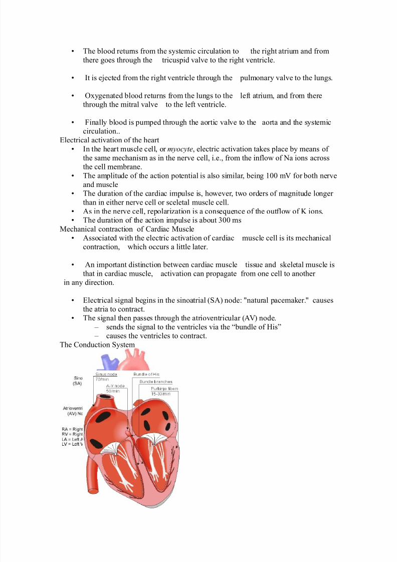
< *lectrical signal begins in the sinoatrial (%" node: Mnatural &acema/er.M causesthe atria to contract.
< The signal then &asses through the atrioventricular (%?" node.
5 sends the signal to the ventricles via the Jbundle of -isK 5 causes the ventricles to contract.
The Conduction ystem
7/27/2019 Ec2021 Notes
http://slidepdf.com/reader/full/ec2021-notes 16/54
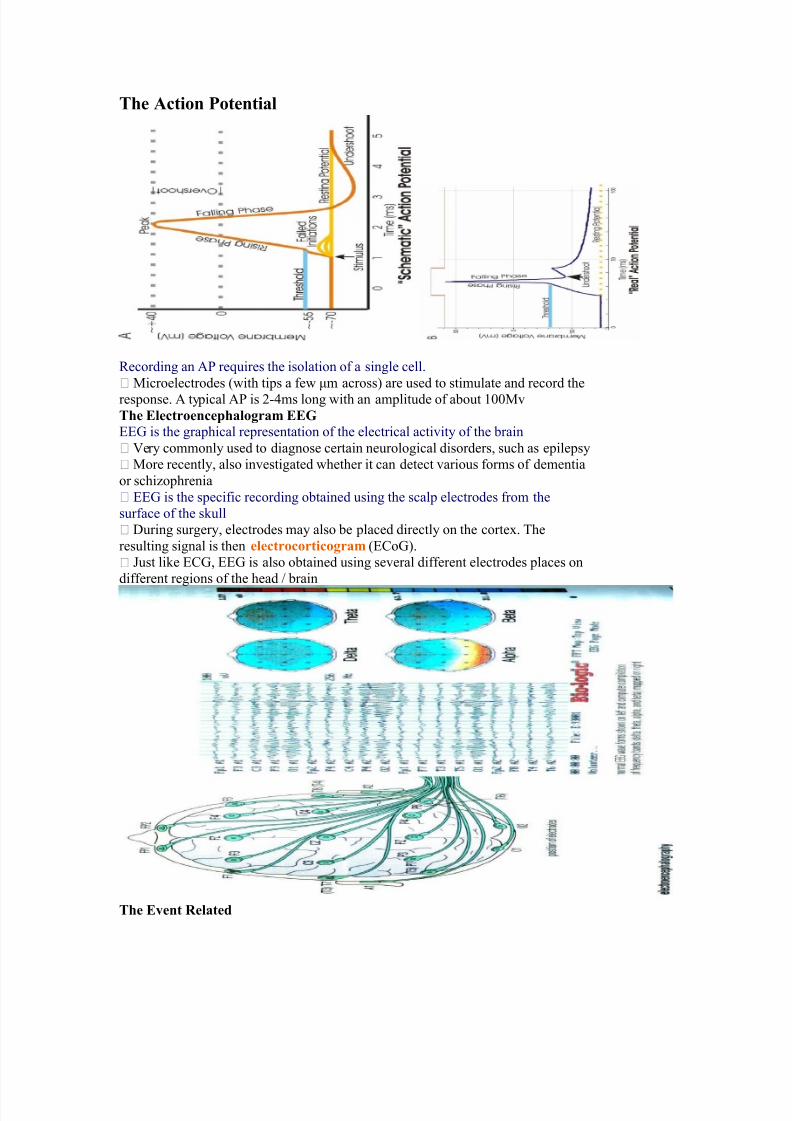
=$e ction Potential
#ecording an % reuires the isolation of a single cell.
1icroelectrodes (with ti&s a few Nm across" are used to stimulate and record the
res&onse. % ty&ical % is 3!=ms long with an am&litude of about 2++1v
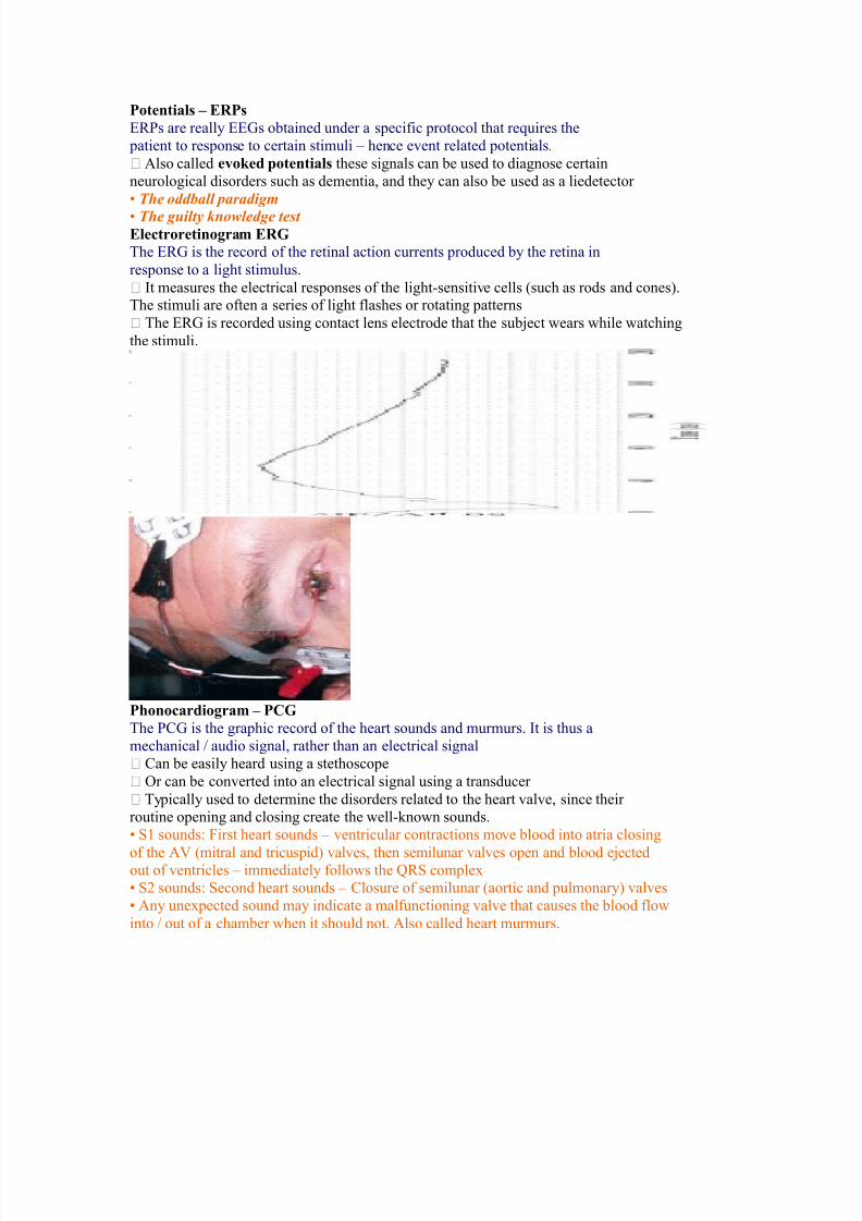
=$e Electroence$alo(ra" EEG
**$ is the gra&hical re&resentation of the electrical activity of the brain
?ery commonly used to diagnose certain neurological disorders, such as e&ile&sy
1ore recently, also investigated whether it can detect various forms of dementia
or schizo&hrenia
**$ is the s&ecific recording obtained using the scal& electrodes from the
surface of the s/ull
7uring surgery, electrodes may also be &laced directly on the cortex. The
resulting signal is then electrocortico(ra" (*Co$".
ust li/e *C$, **$ is also obtained using several different electrodes &laces on
different regions of the head 0 brain
=$e E+ent &elated
7/27/2019 Ec2021 Notes
http://slidepdf.com/reader/full/ec2021-notes 17/54
Potentials – E&Ps
*#s are really **$s obtained under a s&ecific &rotocol that reuires the
&atient to res&onse to certain stimuli 5 hence event related &otentials.
%lso called e+o,ed otentials these signals can be used to diagnose certain
neurological disorders such as dementia, and they can also be used as a liedetector
< The oddball paradigm
< The guilty knowledge test Electroretino(ra" E&G
The *#$ is the record of the retinal action currents &roduced by the retina in
res&onse to a light stimulus.
It measures the electrical res&onses of the light!sensitive cells (such as rods and cones".The stimuli are often a series of light flashes or rotating &atterns
The *#$ is recorded using contact lens electrode that the subDect wears while watching
the stimuli.
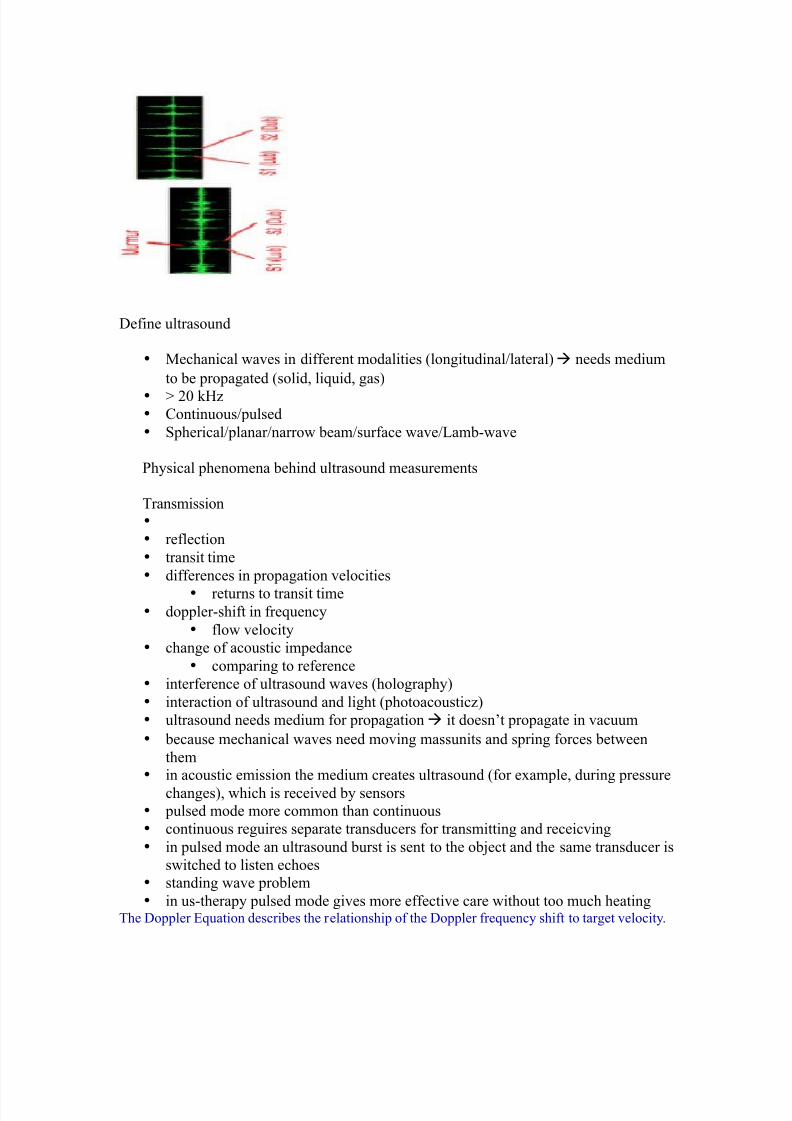
P$onocardio(ra" – PCG
The C$ is the gra&hic record of the heart sounds and murmurs. It is thus a
mechanical 0 audio signal, rather than an electrical signal
Can be easily heard using a stethosco&e
Or can be converted into an electrical signal using a transducer
Ty&ically used to determine the disorders related to the heart valve, since their
routine o&ening and closing create the well!/nown sounds.
< 2 sounds: 4irst heart sounds 5 ventricular contractions move blood into atria closing
of the %? (mitral and tricus&id" valves, then semilunar valves o&en and blood eDectedout of ventricles 5 immediately follows the G# com&lex
< 3 sounds: econd heart sounds 5 Closure of semilunar (aortic and &ulmonary" valves
< %ny unex&ected sound may indicate a malfunctioning valve that causes the blood flow
into 0 out of a chamber when it should not. %lso called heart murmurs.
7/27/2019 Ec2021 Notes
http://slidepdf.com/reader/full/ec2021-notes 18/54
7efine ultrasound
• 1echanical waves in different modalities (longitudinal0lateral"à needs medium
to be &ro&agated (solid, liuid, gas"
• P 3+ /-z• Continuous0&ulsed
• &herical0&lanar0narrow beam0surface wave0amb!wave
hysical &henomena behind ultrasound measurements
Transmission•
• reflection
• transit time
• differences in &ro&agation velocities
• returns to transit time• do&&ler!shift in freuency
• flow velocity
• change of acoustic im&edance
• comå to reference
• interference of ultrasound waves (hologra&hy"
• interaction of ultrasound and light (&hotoacousticz"
• ultrasound needs medium for &ro&agation à it doesnt &ro&agate in vacuum
• because mechanical waves need moving massunits and s&ring forces between
them• in acoustic emission the medium creates ultrasound (for exam&le, during &ressure
changes", which is received by sensors
• &ulsed mode more common than continuous
• continuous reguires se&arate transducers for transmitting and receicving
• in &ulsed mode an ultrasound burst is sent to the obDect and the same transducer is
switched to listen echoes
• standing wave &roblem
• in us!thera&y &ulsed mode gives more effective care without too much heatingThe 7o&&ler *uation describes the relationshi& of the 7o&&ler freuency shift to target velocity.
7/27/2019 Ec2021 Notes
http://slidepdf.com/reader/full/ec2021-notes 19/54
The freuency difference is eual to the reflected freuency (4#" minus the originating freuency
(4T". If the resulting freuency is higher, then there is a &ositive 7o&&ler shift and the obDect is
moving toward the transducer, but if the resulting freuency is lower, there is a negative 7o&&ler
shift and it is moving away from the transducer. In its sim&lest form it would be calculated as if
the ultrasound was &arallel to the targets direction, as shown in diagram below.-owever, this would be a rare occurrence in clinical &ractice, because the transducer is rarely
&ointed head on to a blood vessel. In real life, the ultrasound waves would a&&roach the targetat an angle, called the 7o&&ler angle ( ". On the following &age, diagram B shows the 7o&&ler
euation used in general clinical situations, which includes the 7o&&ler angle.
=$e /oler n(le
The ultrasound beam usually a&&roaches the moving target at an angle called the
Doppler angle 3 4. This reduces the freuency shift in &ro&ortion to the cosine of this
angle. If this angle is /nown then the flow velocity can be calculated. The euation used
is:
=$e /oler Equation
Q 7o&&ler shift freuency (the difference between the transmitted and
received freuencies"
Q transmitted freuency
Q reflected freuency8 Q velocity of the blood flow towards the transducer
C Q velocity of sound in tissue
R Q the angle between the sound beam and the direction of moving blood
.$ere'
The 7o&&ler angle ( " is also /nown as the angle of insonation. It is estimated by
the sonogra&her by a &rocess /nown as angle correction, which involves aligning an
indicator on the du&lex image along the longitudinal axis of the vessel.
There are a few considerations that affect the &erformance of a 7o&&ler
examination that are inherent in the 7o&&ler euation, which are:
5 The cosine of S+ is zero, so if the ultrasound beam is &er&endicular to the
direction of blood flow, there will be no 7o&&ler shift and it will a&&ear as if
there is no flow in the vessel. 5 %&&ro&riate estimation of the angle of insonation, or angle correction, is
essential for the accurate determination of 7o&&ler shift and blood flow velocity.
The angle of insonation should also be less than U+ at all times, since the
cosine function has a stee&er curve above this angle, and errors in angle
correction will be magnified.
The sim&lest 7o&&ler devices use continuous wave (C' 7o&&ler", rather than the &ulsedwave used in more com&lex devices. C' 7o&&ler uses two transducers (or a dual element
transducer" that transmit and receive ultrasound continuously. The transmit and receive
beams overla& in a 7o&&ler sam&le volume some distance from the transducer face, as
shown in the diagram below.volume" is the region of transmitting and receiving beam overla& (shaded region".
9ecause there is continuous transducer transmission and rece&tion, echoes from allde&ths within the area arrive at the transducer simultaneously.
o although C' 7o&&ler can determine the direction of flow, it cannot discriminate
the different de&ths where the motion originates. The usefulness of C' 7o&&ler
devices is limited, but they are used clinically to confirm blood flow in su&erficial
vessels, as they are good at detecting low velocities. %s they are easily &ortable, this
can be done at the bedside or in the o&erating room. 1ost other clinical a&&lications
reuire &ulsed wave 7o&&ler.
Pulsed .a+e /oler 3P. /oler4
7/27/2019 Ec2021 Notes
http://slidepdf.com/reader/full/ec2021-notes 20/54
ulsed wave 7o&&ler (' 7o&&ler" uses a single!element transducer that emits brief
&ulses of ultrasound energy. The time interval between transmitting and then receiving the
echoing sound can be used to calculate the de&th from where the echo arises.
The 7o&&ler sam&le volume can be chosen as to sha&e, de&th, and &osition in sam&ling the flow
data. 4or exam&le, the de&th is chosen by &rocessing only the signals that return to the transducerin a sti&ulated time. 4or this techniue, the ultrasound system transmits a short &ulse. The eceiver
is o&ened to detect the returning echoes only after a controlled delay, and only for a s&ecificduration. This time!based gating of the receiving channel allows the definition of a fixed
easuring distance which is often referred to as the am&le volume or 7o&&ler gate.
Then the next ultrasound wave is transmitted. The number of &ulses transmitted by the system
within a second is referred to as the &ulse re&etition freuency (#4". The u&&er #4 limit is
given by the time interval reuired for the echoes to arrive from a sam&le volume located at a
certain de&th. The greater the sam&le!volume de&th, the longer the time before the echoes are
returned, and the longer the delay between &ulse transmission. The greater the sam&levolume
de&th, the lower will be the maximum #4 setting. *rrors in the accuracy of the information
arise if the velocities exceed a certain s&eed. The highest velocity accurately measured is called
the )yuist limit. 9eyond this limit, the errors that occur are referred to as aliasing .
?olume and flow measurement 4low 5 volume of a liuid0gas &assing some &oint over a given time
$ases are com&ressible
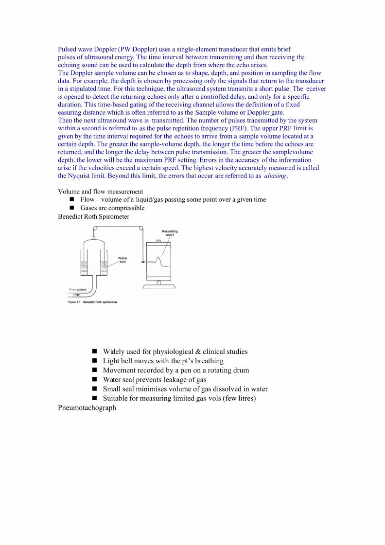
9enedict #oth &irometer
'idely used for &hysiological H clinical studies
ight bell moves with the &ts breathing
1ovement recorded by a &en on a rotating drum
'ater seal &revents lea/age of gas
mall seal minimises volume of gas dissolved in water
uitable for measuring limited gas vols (few litres"
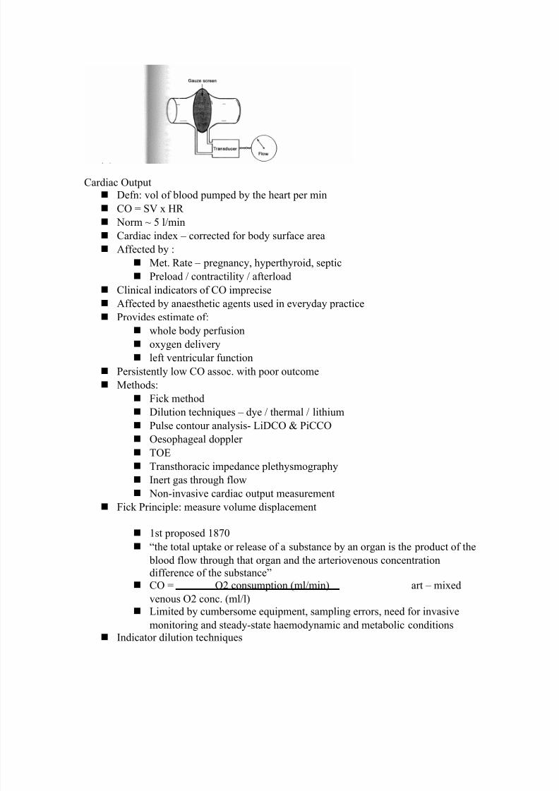
neumotachogra&h
7/27/2019 Ec2021 Notes
http://slidepdf.com/reader/full/ec2021-notes 21/54
7/27/2019 Ec2021 Notes
http://slidepdf.com/reader/full/ec2021-notes 22/54
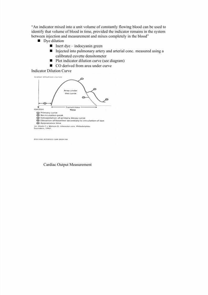
J%n indicator mixed into a unit volume of constantly flowing blood can be used to
identify that volume of blood in time, &rovided the indicator remains in the system
between inDection and measurement and mixes com&letely in the bloodK 7ye dilution
Inert dye 5 indocyanin green
InDected into &ulmonary artery and arterial conc. measured using acalibrated cuvette densitometer
lot indicator dilution curve (see diagram"
CO derived from area under curve
Indicator 7ilution Curve
Cardiac Out&ut 1easurement
7/27/2019 Ec2021 Notes
http://slidepdf.com/reader/full/ec2021-notes 23/54
7/27/2019 Ec2021 Notes
http://slidepdf.com/reader/full/ec2021-notes 24/54
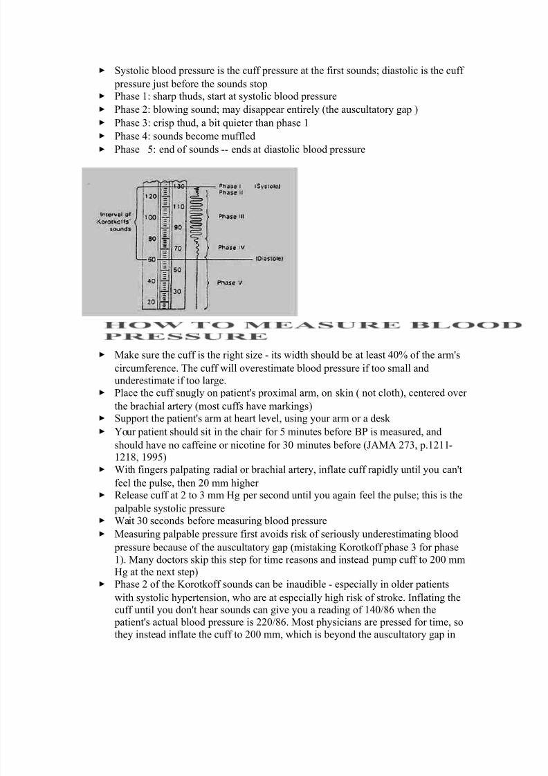
ystolic blood &ressure is the cuff &ressure at the first sounds6 diastolic is the cuff
&ressure Dust before the sounds sto& hase 2: shar& thuds, start at systolic blood &ressure
hase 3: blowing sound6 may disa&&ear entirely (the auscultatory ga& "
hase : cris& thud, a bit uieter than &hase 2
hase =: sounds become muffled hase F: end of sounds !! ends at diastolic blood &ressure
1a/e sure the cuff is the right size ! its width should be at least =+ of the armYs
circumference. The cuff will overestimate blood &ressure if too small and
underestimate if too large. lace the cuff snugly on &atientYs &roximal arm, on s/in ( not cloth", centered over
the brachial artery (most cuffs have mar/ings" u&&ort the &atientYs arm at heart level, using your arm or a des/
>our &atient should sit in the chair for F minutes before 9 is measured, and
should have no caffeine or nicotine for + minutes before (%1% 3X, &.2322!232W, 2SSF"
'ith fingers &al&ating radial or brachial artery, inflate cuff ra&idly until you canYt
feel the &ulse, then 3+ mm higher #elease cuff at 3 to mm -g &er second until you again feel the &ulse6 this is the
&al&able systolic &ressure 'ait + seconds before measuring blood &ressure
1easuring &al&able &ressure first avoids ris/ of seriously underestimating blood
&ressure because of the auscultatory ga& (mista/ing Lorot/off &hase for &hase2". 1any doctors s/i& this ste& for time reasons and instead &um& cuff to 3++ mm
-g at the next ste&" hase 3 of the Lorot/off sounds can be inaudible ! es&ecially in older &atients
with systolic hy&ertension, who are at es&ecially high ris/ of stro/e. Inflating thecuff until you donYt hear sounds can give you a reading of 2=+0WU when the
&atientYs actual blood &ressure is 33+0WU. 1ost &hysicians are &ressed for time, so
they instead inflate the cuff to 3++ mm, which is beyond the auscultatory ga& in
7/27/2019 Ec2021 Notes
http://slidepdf.com/reader/full/ec2021-notes 25/54
most &atients. 9ut &al&able systolic blood &ressure is, according to research, more
reliable. lace bell of stethosco&e (dia&hragm is acce&table" over brachial artery
#a&idly &um& the cuff to 3+ to + mm -g above &al&able systolic &ressure
#elease &ressure in the cuff by 3 to mm -g &er second and listen for Lorot/off
sounds, including systolic (first" and diastolic (last" #ecord as systolic0diastolic. Chec/ in both arms the first time you chec/ a
&atientYs blood &ressure. It may differ by 2+ mm -g or more. If the sounds continues to zero, record diastolic blood &ressure as the &oint when
sounds become muffled (&hase =" over zero: e.g. 2+0X+0+, or Dust as 2+0X+.
#ate
5 )umber of beats in + seconds x 3 trength
5 9ounding, strong, or wea/ (thready"
#egularity
5 #egular or irregular
>ou need three readings on two occasions to diagnose hy&ertension, unless blood
&ressure is very high )ormal blood &ressure in children is:
5 2+30FF at 2 year, 2230US at F years, 22S0XW at 2+ years 9lood &ressures in adults ()C ?II: %1% 3WS:3FU+!X3, 3++":
5 )ormal: Z23+0ZW+
5 rehy&ertensive: 23+!2S0W+!WS
5 tage 2 hy&ertension: 2=+!2FS0S+!SS
5 tage 3 hy&ertension: P2U+0P2++ %dult: U+ to 2++
)ewborn: 23+!2X+
2 year: W+!2U+
years: W+!23+
U years: XF!22F
2+ years: X+!22+
Ho# to "easure' observe rise and fall of chest
In infants, count for U+ seconds6 in adults, 2F or + seconds Nor"al resiration'
%dults: 23 to 3+
Children:
newborn +!W+
2 year 3+!=+
years 3+!+
7/27/2019 Ec2021 Notes
http://slidepdf.com/reader/full/ec2021-notes 26/54
U years 2U!33
#ate
)umber of breaths in + seconds x 3
Guality
Character of breathing
#hythm #egular or irregular
*ffort
)ormal or labored
)oisy res&iration
)ormal, stridor, wheezing, snoring, gurgling
7e&th
hallow or dee&
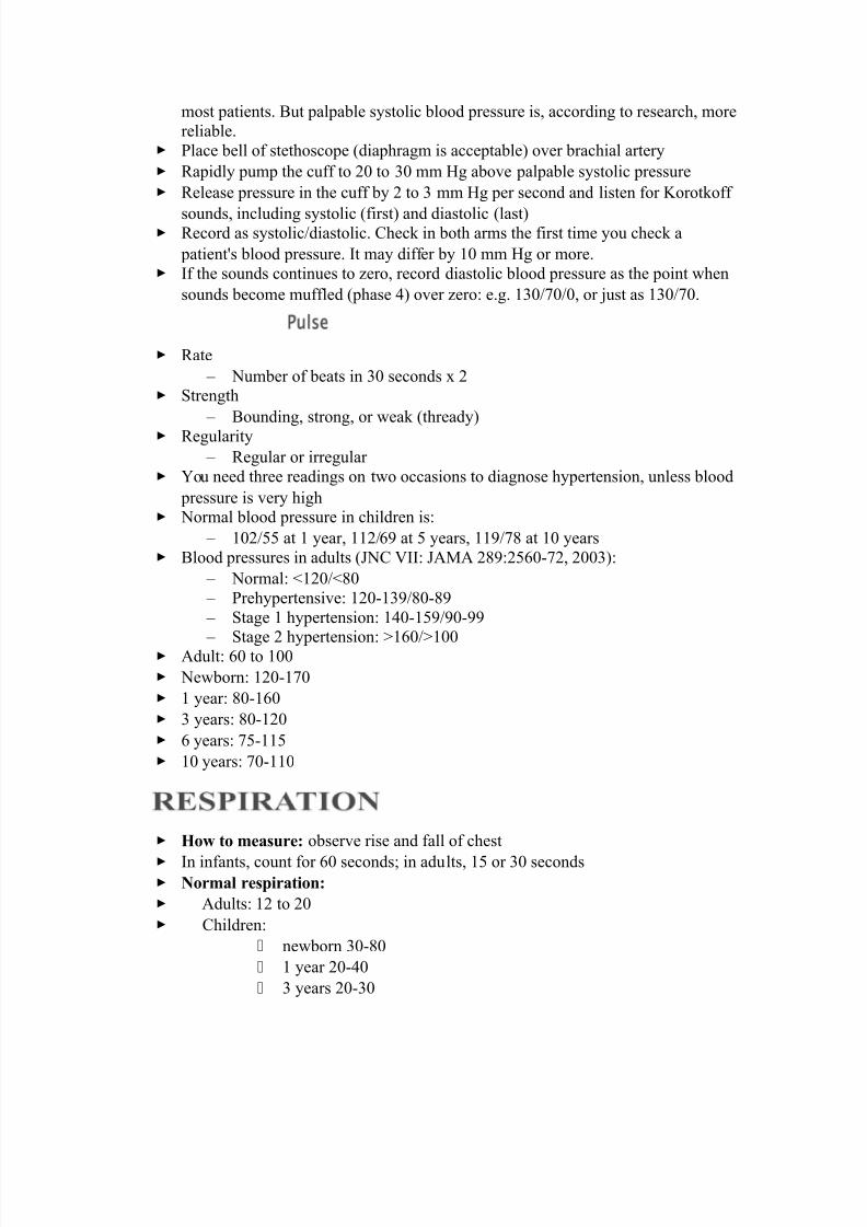
&- electrode
$overning euation is the )ernst *uation
&CO3 *lectrode
The measurement of &CO3 is based on its linear relationshi& with &- over the range of
2+ to S+ mm -g.
The dissociation constant is given by
Ta/ing logarithms
&- A log[-CO!\ 5 log / 5 log a 5 log &CO3
[ ]
[ ] E
R T
n F
i
=
l n
+
! C ! C ! C !3 3 3 : :+ ⇔ ⇔ ++ −
[ ] [ ]"
C !
a p C !=
⋅
+ −
:
3
7/27/2019 Ec2021 Notes
http://slidepdf.com/reader/full/ec2021-notes 27/54
Diathermy
In the natural sciences , the term diathermy means electrically induced heat and is
commonly used for muscle rela!ation. It is also a method of heating tissue
electromagnetically or ultrasonically for therapeutic purposes in medicine.Contents
[hide\• 2 -eating uses
• 3 urgical uses
• Trivia
= #eferences
•
Heating uses
]ltrasonic diathermy refers to heating of tissues by ultrasound for the &ur&ose of
thera&eutic dee& heating. )o tissue is ordinarily damaged hence it is generally used in biomedical a&&lications.
*lectric diathermy uses high freuency alternating electric or magnetic fields, sometimes
with no electrode or device contact to the s/in, to induce gentle dee& tissue heating by
induction. %gain, no tissue is ordinarily damaged.
Surgical uses
#urgical diathermy is usually better /nown as Melectrosurgery.M (It is also referred to
occasionally as MelectrocauteryM, but see disambiguation below". *lectrosurgery and
surgical diathermy involve the use of high freuency %.C. electrical current in surgery aseither a cutting modality, or else to cauterize small blood vessels to sto& bleeding. This
techniue induces localized tissue burning and damage, the zone of which is controlled
by the freuency and &ower of the device. ome sources[2\ insist that electrosurgery bea&&lied to surgery accom&lished by high freuency %.C. cutting, and that
MelectrocauteryM be used only for the &ractice of cauterization with heated nichrome wires
&owered by 7.C. current, as in the handheld battery!o&erated &ortable cautery tools.
Trivia
1edical 7iathermy devices were used to cause interference to $erman radio beams used
for targeting night time bombing raids in ''II during the 9attle of the 9eams.
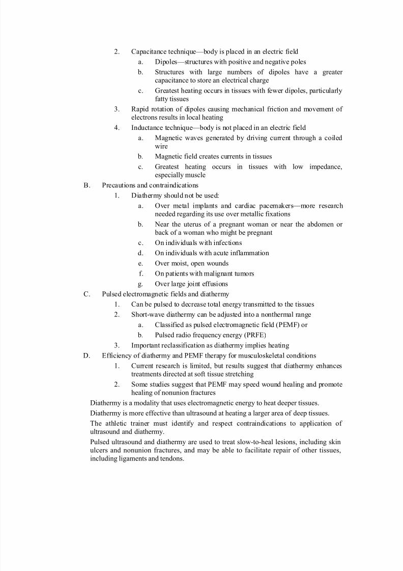
I. 7iathermy
%. Thera&eutic use
2. $eneration of local heating by high!freuency electromagnetic waves
7/27/2019 Ec2021 Notes
http://slidepdf.com/reader/full/ec2021-notes 28/54
3. Ca&acitance techniue^body is &laced in an electric field
a. 7i&oles^structures with &ositive and negative &oles
b. tructures with large numbers of di&oles have a greater
ca&acitance to store an electrical charge
c. $reatest heating occurs in tissues with fewer di&oles, &articularly
fatty tissues. #a&id rotation of di&oles causing mechanical friction and movement of
electrons results in local heating
=. Inductance techniue^body is not &laced in an electric field
a. 1agnetic waves generated by driving current through a coiled
wire
b. 1agnetic field creates currents in tissues
c. $reatest heating occurs in tissues with low im&edance,
es&ecially muscle
9. recautions and contraindications
2. 7iathermy should not be used:
a. Over metal im&lants and cardiac &acema/ers^more research
needed regarding its use over metallic fixations
b. )ear the uterus of a ®nant woman or near the abdomen or
bac/ of a woman who might be ®nant
c. On individuals with infections
d. On individuals with acute inflammation
e. Over moist, o&en wounds
f. On &atients with malignant tumors
g. Over large Doint effusions
C. ulsed electromagnetic fields and diathermy
2. Can be &ulsed to decrease total energy transmitted to the tissues
3. hort!wave diathermy can be adDusted into a nonthermal range
a. Classified as &ulsed electromagnetic field (*14" or
b. ulsed radio freuency energy (#4*"
. Im&ortant reclassification as diathermy im&lies heating
7. *fficiency of diathermy and *14 thera&y for musculos/eletal conditions
2. Current research is limited, but results suggest that diathermy enhances
treatments directed at soft tissue stretching
3. ome studies suggest that *14 may s&eed wound healing and &romote
healing of nonunion fractures
7iathermy is a modality that uses electromagnetic energy to heat dee&er tissues.
7iathermy is more effective than ultrasound at heating a larger area of dee& tissues.
The athletic trainer must identify and res&ect contraindications to a&&lication of
ultrasound and diathermy.
ulsed ultrasound and diathermy are used to treat slow!to!heal lesions, including s/in
ulcers and nonunion fractures, and may be able to facilitate re&air of other tissues,
including ligaments and tendons.
7/27/2019 Ec2021 Notes
http://slidepdf.com/reader/full/ec2021-notes 29/54
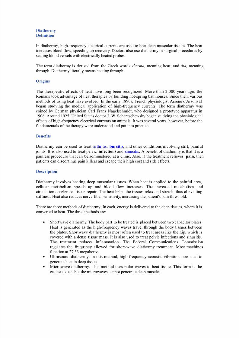
/iat$er"y
/efinition
In diathermy, high!freuency electrical currents are used to heat dee& muscular tissues. The heat
increases blood flow, s&eeding u& recovery. 7octors also use diathermy in surgical &rocedures by
sealing blood vessels with electrically heated &robes.
The term diathermy is derived from the $ree/ words therma$ meaning heat, and dia$ meaning
through. 7iathermy literally means heating through.
9ri(ins
The thera&eutic effects of heat have long been recognized. 1ore than 3,+++ years ago, the
#omans too/ advantage of heat thera&ies by building hot!s&ring bathhouses. ince then, various
methods of using heat have evolved. In the early 2WS+s, 4rench &hysiologist %rs_ne dY%rsonval began studying the medical a&&lication of high!freuency currents. The term diathermy was
coined by $erman &hysician Carl 4ranz )agelschmidt, who designed a &rototy&e a&&aratus in
2S+U. %round 2S3F, ]nited tates doctor . '. chereschews/y began studying the &hysiological
effects of high!freuency electrical currents on animals. It was several years, however, before the
fundamentals of the thera&y were understood and &ut into &ractice.
Benefits
7iathermy can be used to treat arthritis, !ursitis, and other conditions involving stiff, &ainful
Doints. It is also used to treat &elvic infections and sinusitis. % benefit of diathermy is that it is a
&ainless &rocedure that can be administered at a clinic. %lso, if the treatment relieves ain, then
&atients can discontinue &ain /illers and esca&e their high cost and side effects.
/escrition
7iathermy involves heating dee& muscular tissues. 'hen heat is a&&lied to the &ainful area,
cellular metabolism s&eeds u& and blood flow increases. The increased metabolism and
circulation accelerates tissue re&air. The heat hel&s the tissues relax and stretch, thus alleviating
stiffness. -eat also reduces nerve fiber sensitivity, increasing the &atientYs &ain threshold.
There are three methods of diathermy. In each, energy is delivered to the dee& tissues, where it is
converted to heat. The three methods are:
• hortwave diathermy. The body &art to be treated is &laced between two ca&acitor &lates.
-eat is generated as the high!freuency waves travel through the body tissues between
the &lates. hortwave diathermy is most often used to treat areas li/e the hi&, which is
covered with a dense tissue mass. It is also used to treat &elvic infections and sinusitis.The treatment reduces inflammation. The 4ederal Communications Commission
regulates the freuency allowed for short!wave diathermy treatment. 1ost machines
function at 3X. megahertz.
• ]ltrasound diathermy. In this method, high!freuency acoustic vibrations are used to
generate heat in dee& tissue.
• 1icrowave diathermy. This method uses radar waves to heat tissue. This form is the
easiest to use, but the microwaves cannot &enetrate dee& muscles.
7/27/2019 Ec2021 Notes
http://slidepdf.com/reader/full/ec2021-notes 30/54
7/27/2019 Ec2021 Notes
http://slidepdf.com/reader/full/ec2021-notes 31/54
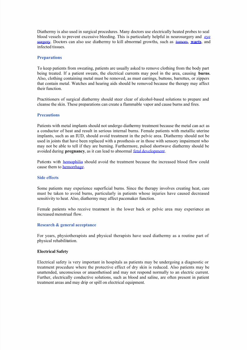
← *lectric Current
← ea/age Current
← *xtension eads
← 7ouble %da&tors
← *ui&ment Classification
← Class I
← Class II
← 7efibrillator!roof
← rotective 7evices
← #esidual Current 7evices (#C7"
← ine Isolation overload 1onitors (I1s"
← *ui&ment *arthing
← %rea Classification
← 9ody rotection %rea
← Cardiac rotected %rea
← Other *lectrical Issues
← *xtension eads
← 7ouble %da&ters← 1ain *xtension 7evices
← ower 9oards
← Installation of %dditional ower oints
Electric Current
InDuries received from electric current are de&endent on the magnitude of current, the &athway
that it ta/es through the body and the time for which it flows.
The nature of electricity flowing through a circuit is analogous to blood flowing through the
circulatory system within the human body. In this analogy the source of energy is re&resented by
the heart, and the blood flowing through arteries and veins is analagous to current flowingthrough the conductors and other com&onents of the electric circuit.
The a&&lication of an electric &otential to an electric circuit generates a flow of current through
conductive &athways. This is analogous to the changes in blood &ressure caused by contraction of
cardiac muscle that causes blood to flow into the circulatory system. 4or electric current to flow
there must be a continuous &athway from the source of &otential through electrical com&onents
and bac/ to the source.
"eakage Current
*lectrical com&onents and systems are encased in non conducting insulation, to ensure that the
electric current is contained and follows the intended &athways. If the insulation deteriorates or
brea/s down, current will lea/ through the insulation barrier and flow to earth. This may be through the &rotective earth conductor or through the o&erator.
1edical eui&ment and clinical areas are fitted with a number of &rotective devices to &rotect the
&atient and o&erator from harmful lea/age currents.
7/27/2019 Ec2021 Notes
http://slidepdf.com/reader/full/ec2021-notes 32/54
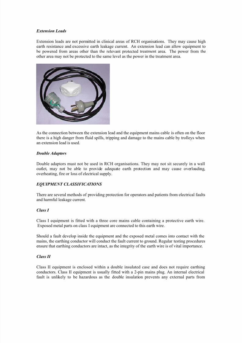
E!tension "eads
*xtension leads are not &ermitted in clinical areas of #C- organisations. They may cause high
earth resistance and excessive earth lea/age current. %n extension lead can allow eui&ment to
be &owered from areas other than the relevant &rotected treatment area. The &ower from the
other area may not be &rotected to the same level as the &ower in the treatment area.
%s the connection between the extension lead and the eui&ment mains cable is often on the floor
there is a high danger from fluid s&ills, tri&&ing and damage to the mains cable by trolleys when
an extension lead is used.
Double #daptors
7ouble ada&tors must not be used in #C- organisations. They may not sit securely in a walloutlet, may not be able to &rovide adeuate earth &rotection and may cause overloading,
overheating, fire or loss of electrical su&&ly.
E$%IP&E'T C"#((I)IC#TI*'(
There are several methods of &roviding &rotection for o&erators and &atients from electrical faults
and harmful lea/age current.
Class I
Class I eui&ment is fitted with a three core mains cable containing a &rotective earth wire.
*x&osed metal &arts on class I eui&ment are connected to this earth wire.
hould a fault develo& inside the eui&ment and the ex&osed metal comes into contact with the
mains, the earthing conductor will conduct the fault current to ground. #egular testing &roceduresensure that earthing conductors are intact, as the integrity of the earth wire is of vital im&ortance.
Class II
Class II eui&ment is enclosed within a double insulated case and does not reuire earthing
conductors. Class II eui&ment is usually fitted with a 3!&in mains &lug. %n internal electrical
fault is unli/ely to be hazardous as the double insulation &revents any external &arts from
7/27/2019 Ec2021 Notes
http://slidepdf.com/reader/full/ec2021-notes 33/54
becoming alive. Class II or double insulated eui&ment can be identified by the class II symbol
on the cabinet.
Class II ymbol:
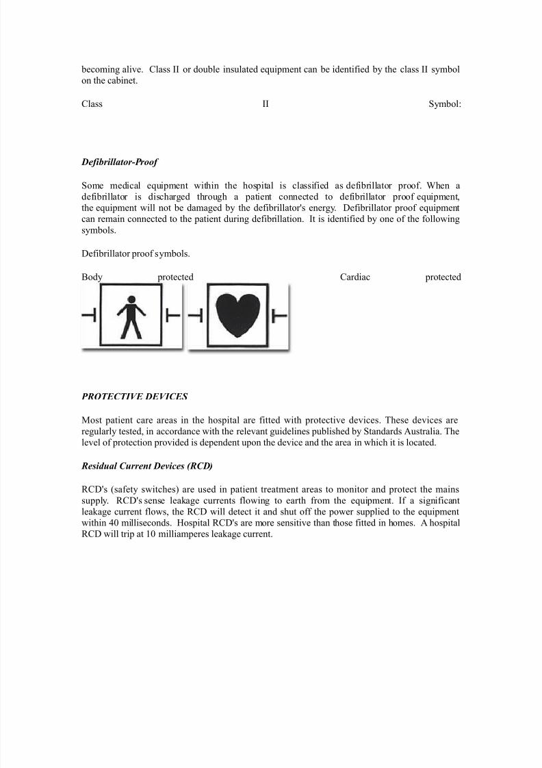
Defibrillator+Proof
ome medical eui&ment within the hos&ital is classified as defibrillator &roof. 'hen a
defibrillator is discharged through a &atient connected to defibrillator &roof eui&ment,
the eui&ment will not be damaged by the defibrillatorYs energy. 7efibrillator &roof eui&ment
can remain connected to the &atient during defibrillation. It is identified by one of the following
symbols.
7efibrillator &roof symbols.
9ody &rotected Cardiac &rotected
PR*TECTIE DEICE(
1ost &atient care areas in the hos&ital are fitted with &rotective devices. These devices are
regularly tested, in accordance with the relevant guidelines &ublished by tandards %ustralia. The
level of &rotection &rovided is de&endent u&on the device and the area in which it is located.
Residual Current De-ices RCD/
#C7Ys (safety switches" are used in &atient treatment areas to monitor and &rotect the mains
su&&ly. #C7Ys sense lea/age currents flowing to earth from the eui&ment. If a significant
lea/age current flows, the #C7 will detect it and shut off the &ower su&&lied to the eui&ment
within =+ milliseconds. -os&ital #C7Ys are more sensitive than those fitted in homes. % hos&ital
#C7 will tri& at 2+ milliam&eres lea/age current.
7/27/2019 Ec2021 Notes
http://slidepdf.com/reader/full/ec2021-notes 34/54
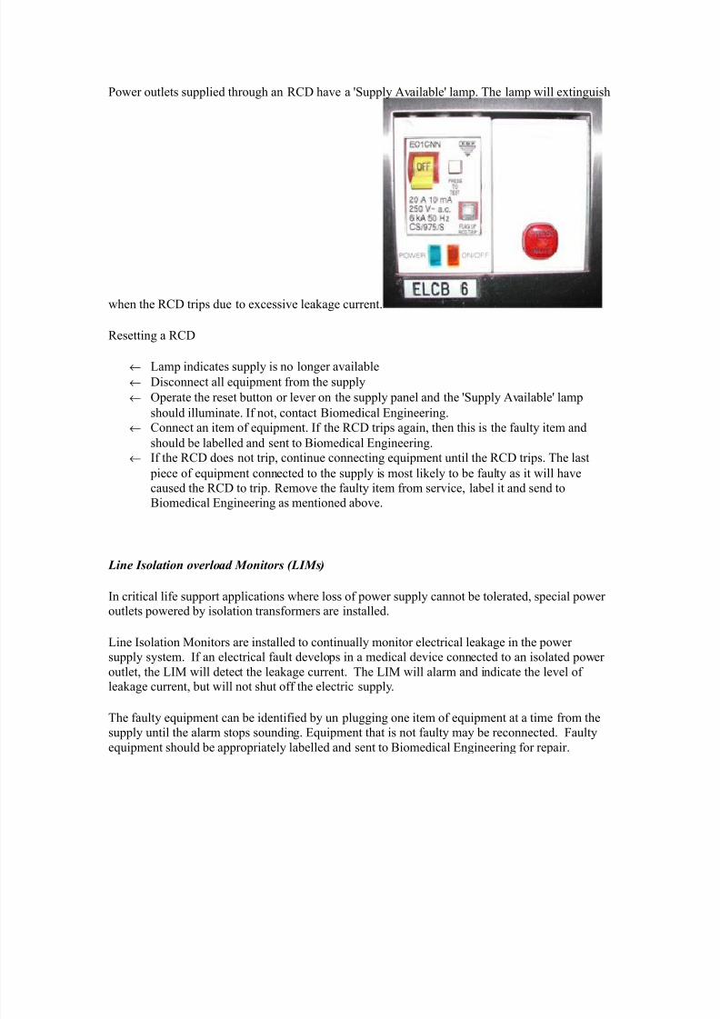
ower outlets su&&lied through an #C7 have a Yu&&ly %vailableY lam&. The lam& will extinguish
when the #C7 tri&s due to excessive lea/age current.
#esetting a #C7
← am& indicates su&&ly is no longer available
← 7isconnect all eui&ment from the su&&ly
← O&erate the reset button or lever on the su&&ly &anel and the Yu&&ly %vailableY lam&
should illuminate. If not, contact 9iomedical *ngineering.
← Connect an item of eui&ment. If the #C7 tri&s again, then this is the faulty item and
should be labelled and sent to 9iomedical *ngineering.
← If the #C7 does not tri&, continue connecting eui&ment until the #C7 tri&s. The last
&iece of eui&ment connected to the su&&ly is most li/ely to be faulty as it will have
caused the #C7 to tri&. #emove the faulty item from service, label it and send to
9iomedical *ngineering as mentioned above.
"ine Isolation o-erload &onitors "I&s/
In critical life su&&ort a&&lications where loss of &ower su&&ly cannot be tolerated, s&ecial &oweroutlets &owered by isolation transformers are installed.
ine Isolation 1onitors are installed to continually monitor electrical lea/age in the &ower
su&&ly system. If an electrical fault develo&s in a medical device connected to an isolated &ower
outlet, the I1 will detect the lea/age current. The I1 will alarm and indicate the level oflea/age current, but will not shut off the electric su&&ly.
The faulty eui&ment can be identified by un &lugging one item of eui&ment at a time from thesu&&ly until the alarm sto&s sounding. *ui&ment that is not faulty may be reconnected. 4aulty
eui&ment should be a&&ro&riately labelled and sent to 9iomedical *ngineering for re&air.
7/27/2019 Ec2021 Notes
http://slidepdf.com/reader/full/ec2021-notes 35/54
The I1 also monitors how much &ower is being used by the eu&iment connected to it. If too
much &ower is being used, the I1 will alarm and indicate that there is an overload. The &ower
used must be reduced immediately by moving some eui&ment to another circuit as soon as
&ossible until the alarm sto&s sounding. 4ailure to reduce the load on the I1 will result in the
circuit brea/er tri&&ing and loss of &ower to the circuit.
E0uipotential Earthing
*ui&otential earthing is installed in rooms classified as YCardiac rotectedY electrical areas.
*ui&otential earthing in treatment areas used for cardiac &rocedures is intended to minimise any
voltage differences between earthed &arts of eui&ment and any other ex&osed metal in the room.
This reduces the &ossibility of lea/age currents that can cause microelectrocution when the
&atient comes into contact with multi&le items of eui&ment, or if the &atient ha&&ens to come
into contact with metal items in the room whilr they are connected to a medical device.
%ll conductive metal in an eui&otential area is connected to a common eui&otential earth &ointwith s&ecial heavy duty cable.
#RE# C"#((I)IC#TI*'(
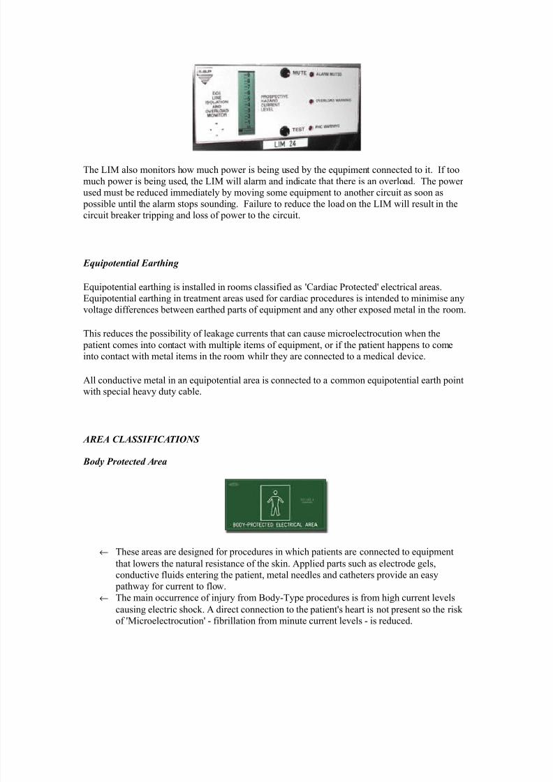
1ody Protected #rea
← These areas are designed for &rocedures in which &atients are connected to eui&ment
that lowers the natural resistance of the s/in. %&&lied &arts such as electrode gels,
conductive fluids entering the &atient, metal needles and catheters &rovide an easy
&athway for current to flow.
← The main occurrence of inDury from 9ody!Ty&e &rocedures is from high current levels
causing electric shoc/. % direct connection to the &atientYs heart is not &resent so the ris/
of Y1icroelectrocutionY ! fibrillation from minute current levels ! is reduced.
7/27/2019 Ec2021 Notes
http://slidepdf.com/reader/full/ec2021-notes 36/54
← #esidual Current 7evices (#C7" or Isolation Transformers and ine Isolation 1onitors
(I1`s", are used in 9ody rotected areas to &rovide &rotection against electrocution
from high lea/age currents. 9ody!rotected %reas are identified with this sign.
Cardiac Protected #rea
← 'here the &rocedure involves &lacing an electrical conductor within or near the heart,
&rotection against fibrillation induced from small lea/age currents is reuired. *lectrical
conductors used in these &rocedures include cardiac &acing electrodes, intracardiac *C$
electrodes and intracardiac catheters.
← *ui&otential earthing in conDunction with #C7Ys or I1Ys &rovides &rotection against
microelectrocution in Cardiac!Ty&e &rocedures.
← 4ault currents are reduced to magnitudes that are unli/ely to induce fibrillation. ]sed in
conDunction with #C7Ys or I1Ys, the magnitude and duration of any fault currents
sourced from eui&ment are limited.
← Cardiac!rotected %reas are identified with this sign.
*ther electrical issues
This &olicy aims to &rovide guidance to those who find that they need more electrical outlets thanthose available, or that the existing electrical outlets are inconveniently located.
%s extension leads and multi&le outlet &ower boards can introduce additional hazards into an area
the following &rocedures should be observed.
E!tension leads
%&&roved extension leads (% XU+, 2SSU" may be used in some areas within the hos&ital but
1]T )OT 9* ]*7 I) %TI*)T %#*%. %ll electrical extension leads must be tagged with
an *ngineering 7e&artment maintenance tag, and reuire a yearly safety ins&ection and test, via
the *ngineering 7e&artment.
Double adapters
7ouble ada&ters may cause overloading or eui&ment earthing &roblems and are not to be used in
'C-

7/27/2019 Ec2021 Notes
http://slidepdf.com/reader/full/ec2021-notes 37/54
&ains e!tension de-ice
The only mains extension device that is to be used in Matient care areasM is the =!way or W!way
&ortable Core 9alance ]nit.
The 9iomedical *ngineering 7e&artment must a&&rove all units &rior to use. These units contain
a safety switch and can detect excessive lea/age current and disconnect the &ower in the event of
a hazardous situation.
Care must be exercised in the use of a &ortable Core 9alance ]nit. It should be located off the
floor and in a &osition that will &rotect it from &hysical abuse and &ossible entry of fluids. These
devices are ex&ensive and easily damaged. The device must be sent to 9iomedical *ngineering
every U months for safety testing.
Power boards
%&&roved multi&le!outlet &ower boards can be used across #C- but must not be used in &atient
care areas, exce&t areas a&&roved by the 9iomedical *ngineering 7e&artment.
The &ower boards must have overload &rotection, be fitted with internal safety shutters that
&rotect unused outlets and be fitted with an on0off switch for each outlet.
7/27/2019 Ec2021 Notes
http://slidepdf.com/reader/full/ec2021-notes 38/54
Medical Laser lications
The main research subDects of the grou& of 1edical aser %&&lication are in the field of online
monitoring and diagnostics as well as the develo&ment of new thera&heutic methods. The main
focus in research is based u&on the use of ultrashort (fs" laser &ulses.
The main advantage of ultrashort laser &ulses is the extrem short interaction time which su&&ress
any unwanted side effects of the laser irradiation of the tissue. econdly the broad s&ectra of the
fs laser &ulses give the advantage to use the same laser &ulses for diagnostic a&&lications li/e the
o&tical coherence tomogra&hy (OCT".
4ollowing research subDects have s&ecial attention at the moment:
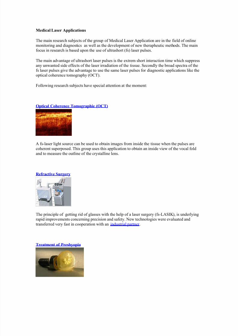
9tical Co$erence =o"o(ra$ie 39C=4
% fs!laser light source can be used to obtain images from inside the tissue when the &ulses are
coherent su&er&osed. This grou& uses this a&&lication to obtain an inside view of the vocal fold
and to measure the outline of the crystalline lens.
&efracti+e )ur(ery
The &rinci&le of getting rid of glasses with the hel& of a laser surgery (fs!%IL", is underlying
ra&id im&rovements concerning &recision and safety. )ew technologies were evaluated and
transferred very fast in coo&eration with an industrial &artner .
=reat"ent of Pres!yoia
7/27/2019 Ec2021 Notes
http://slidepdf.com/reader/full/ec2021-notes 39/54
The flexibility of the crystalline lens can be increase by &ricise cuts which are induce by fs laser
&ulse inside the lens. The treatment of the &resbyo&ia is thin/able.
ltrafast P$ysics
'hereas the a&&lications of ultrashort laser &ulses increase ra&idly is the &hysics of the
interaction between the laser &ulses and tissue in many case not fully understood. To obtain
im&roved /nowledge of the interaction for many fs!laser a&&lication this grou& &reforms
numerical simulations as well as fundamental ex&eriments.
=$er"o(ra$y
=$er"o(ra$y, t$er"al i"a(in(, or t$er"al +ideo, is a ty&e of infrared imaging.
Thermogra&hic cameras detect radiation in the infrared range of the electromagnetic s&ectrum (roughly S++52=,+++ nanometers or +.S52= m" and &roduce images of that radiation. ince
infrared radiation is emitted by all obDects based on their tem&eratures, according to the blac/
body radiation law, thermogra&hy ma/es it &ossible to MseeM oneYs environment with or without
visible illumination. The amount of radiation emitted by an obDect increases with tem&erature,
therefore thermogra&hy allows one to see variations in tem&erature (hence the name". 'hen
viewed by thermogra&hic camera, warm obDects stand out well against cooler bac/grounds6
humans and other warm!blooded animals become easily visible against the environment, day or
night. %s a result, thermogra&hyYs extensive use can historically be ascribed to the military andsecurity services.
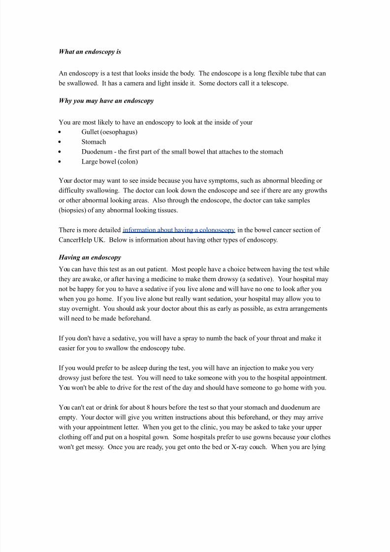
Thermal imaging &hotogra&hy finds many other uses. 4or exam&le, firefighters use it to see
through smo/e, find &ersons, and localize the base of a fire. 'ith thermal imaging, &ower lines maintenance technicians locate overheating Doints and &arts, a telltale sign of their failure, toeliminate &otential hazards. 'here thermal insulation becomes faulty, building construction
technicians can see heat lea/s to im&rove the efficiencies of cooling or heating air!conditioning.
Thermal imaging cameras are also installed in some luxury cars to aid the driver, the first being
the 3+++ Cadillac 7e?ille. ome &hysiological activities, &articularly res&onses, in human beings
and other warm!blooded animals can also be monitored with thermogra&hic imaging. [2\
7/27/2019 Ec2021 Notes
http://slidepdf.com/reader/full/ec2021-notes 40/54
The a&&earance and o&eration of a modern thermogra&hic camera is often similar to a camcorder .
*nabling the user to see in the infrared s&ectrum is a function so useful that ability to record their
out&ut is often o&tional. % recording module is therefore not always built!in.
Instead of CC7 sensors, most thermal imaging cameras use C1O 4ocal lane %rray (4%". The
most common ty&es are Inb, In$a%s, -gCdTe and G'I 4%. The newest technologies are
using low cost and uncooled microbolometers 4% sensors. Their resolution is considerably lower than of o&tical cameras, mostly 2U+x23+ or 3+x3=+ &ixels, u& to U=+xF23 for the most
ex&ensive models. Thermogra&hic cameras are much more ex&ensive than their visible!s&ectrum
counter&arts, and higher!end models are often ex&ort!restricted. Older bolometers or moresensitive models as Inb reuire cryogenic cooling, usually by a miniature tirling cycle
refrigerator or liuid nitrogen.
Contents
[hide\
• 2 7ifference between I# film and thermogra&hy
•
3 %dvantages of Thermogra&hy • imitations H disadvantages of thermogra&hy
• = %&&lications
• F ee also
• U *xternal lin/s
o U.2 -istory of thermal imager manufacturers
2 edit 3 Difference between IR film and thermography
Thermal imaging is going to be used on 1ars to detect caves that could hold life.
2 edit 3 #d-antages of Thermography
• >ou get a visual &icture so that you can com&are tem&eratures over a large area
• It is real time ca&able of catching moving targets
• %ble to find deteriorating com&onents &rior to failure
• 1easurement in areas inaccessible or hazardous for other methods
• It is a non!destructive test method
2 edit 3 "imitations 4 disad-antages of thermography
• Guality cameras are ex&ensive and are easily damaged
• Images can be hard to inter&ret accurately even with ex&erience
• %ccurate tem&erature measurements are very hard to ma/e because of emissivities
• 1ost cameras have 3 or worse accuracy (not as accurate as contact"• Training and staying &roficient in I# scanning is time consuming
• %bility to only measure surface areas
2 edit 3 #pplications
• Condition monitoring
• 1edical imaging
• )ight vision
7/27/2019 Ec2021 Notes
http://slidepdf.com/reader/full/ec2021-notes 41/54
• #esearch
• rocess control
• )on destructive testing
• urveillance in security, law enforcement and defense
• Chemical imaging
Thermal infrared imagers convert the energy in the infrared wavelength into a visible light video
dis&lay. %ll obDects above + /elvins emit thermal infrared energy so thermal imagers can
&assively see all obDects regardless of ambient light. -owever, most thermal imagers only see
obDects warmer than !F+ C.
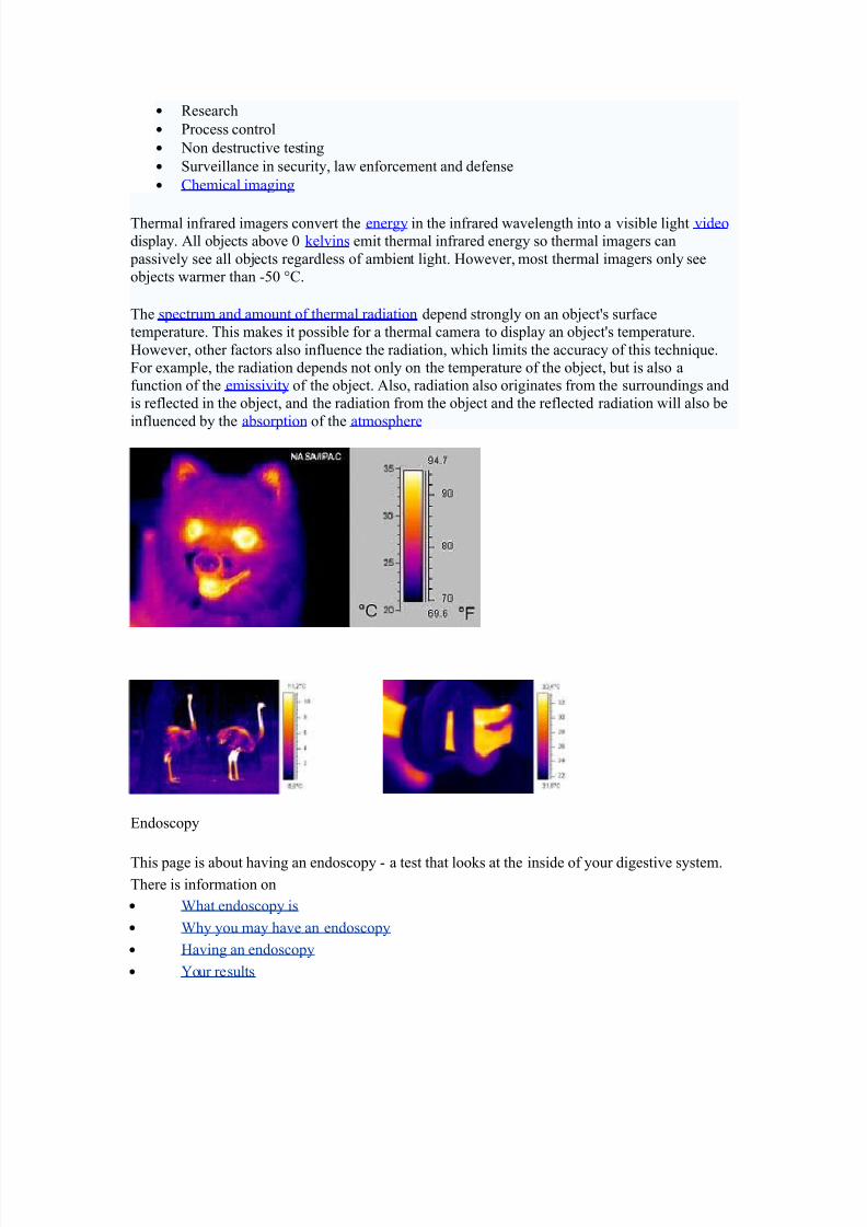
The s&ectrum and amount of thermal radiation de&end strongly on an obDectYs surface
tem&erature. This ma/es it &ossible for a thermal camera to dis&lay an obDectYs tem&erature.
-owever, other factors also influence the radiation, which limits the accuracy of this techniue.
4or exam&le, the radiation de&ends not only on the tem&erature of the obDect, but is also a
function of the emissivity of the obDect. %lso, radiation also originates from the surroundings and
is reflected in the obDect, and the radiation from the obDect and the reflected radiation will also be
influenced by the absor&tion of the atmos&here
*ndosco&y
This &age is about having an endosco&y ! a test that loo/s at the inside of your digestive system.
There is information on
• 'hat endosco&y is
• 'hy you may have an endosco&y
• -aving an endosco&y
• >our results
7/27/2019 Ec2021 Notes
http://slidepdf.com/reader/full/ec2021-notes 42/54
5hat an endoscopy is
%n endosco&y is a test that loo/s inside the body. The endosco&e is a long flexible tube that can
be swallowed. It has a camera and light inside it. ome doctors call it a telesco&e.
5hy you may ha-e an endoscopy
>ou are most li/ely to have an endosco&y to loo/ at the inside of your
• $ullet (oeso&hagus"
• tomach
• 7uodenum ! the first &art of the small bowel that attaches to the stomach
• arge bowel (colon"
>our doctor may want to see inside because you have sym&toms, such as abnormal bleeding or
difficulty swallowing. The doctor can loo/ down the endosco&e and see if there are any growthsor other abnormal loo/ing areas. %lso through the endosco&e, the doctor can ta/e sam&les
(bio&sies" of any abnormal loo/ing tissues.
There is more detailed information about having a colonosco&y in the bowel cancer section of
Cancer-el& ]L. 9elow is information about having other ty&es of endosco&y.
6a-ing an endoscopy
>ou can have this test as an out &atient. 1ost &eo&le have a choice between having the test while
they are awa/e, or after having a medicine to ma/e them drowsy (a sedative". >our hos&ital may
not be ha&&y for you to have a sedative if you live alone and will have no one to loo/ after youwhen you go home. If you live alone but really want sedation, your hos&ital may allow you to
stay overnight. >ou should as/ your doctor about this as early as &ossible, as extra arrangements
will need to be made beforehand.
If you donYt have a sedative, you will have a s&ray to numb the bac/ of your throat and ma/e it
easier for you to swallow the endosco&y tube.
If you would &refer to be aslee& during the test, you will have an inDection to ma/e you very
drowsy Dust before the test. >ou will need to ta/e someone with you to the hos&ital a&&ointment.
>ou wonYt be able to drive for the rest of the day and should have someone to go home with you.
>ou canYt eat or drin/ for about W hours before the test so that your stomach and duodenum are
em&ty. >our doctor will give you written instructions about this beforehand, or they may arrive
with your a&&ointment letter. 'hen you get to the clinic, you may be as/ed to ta/e your u&&er
clothing off and &ut on a hos&ital gown. ome hos&itals &refer to use gowns because your clothes
wonYt get messy. Once you are ready, you get onto the bed or !ray couch. 'hen you are lying
7/27/2019 Ec2021 Notes
http://slidepdf.com/reader/full/ec2021-notes 43/54
7/27/2019 Ec2021 Notes
http://slidepdf.com/reader/full/ec2021-notes 44/54
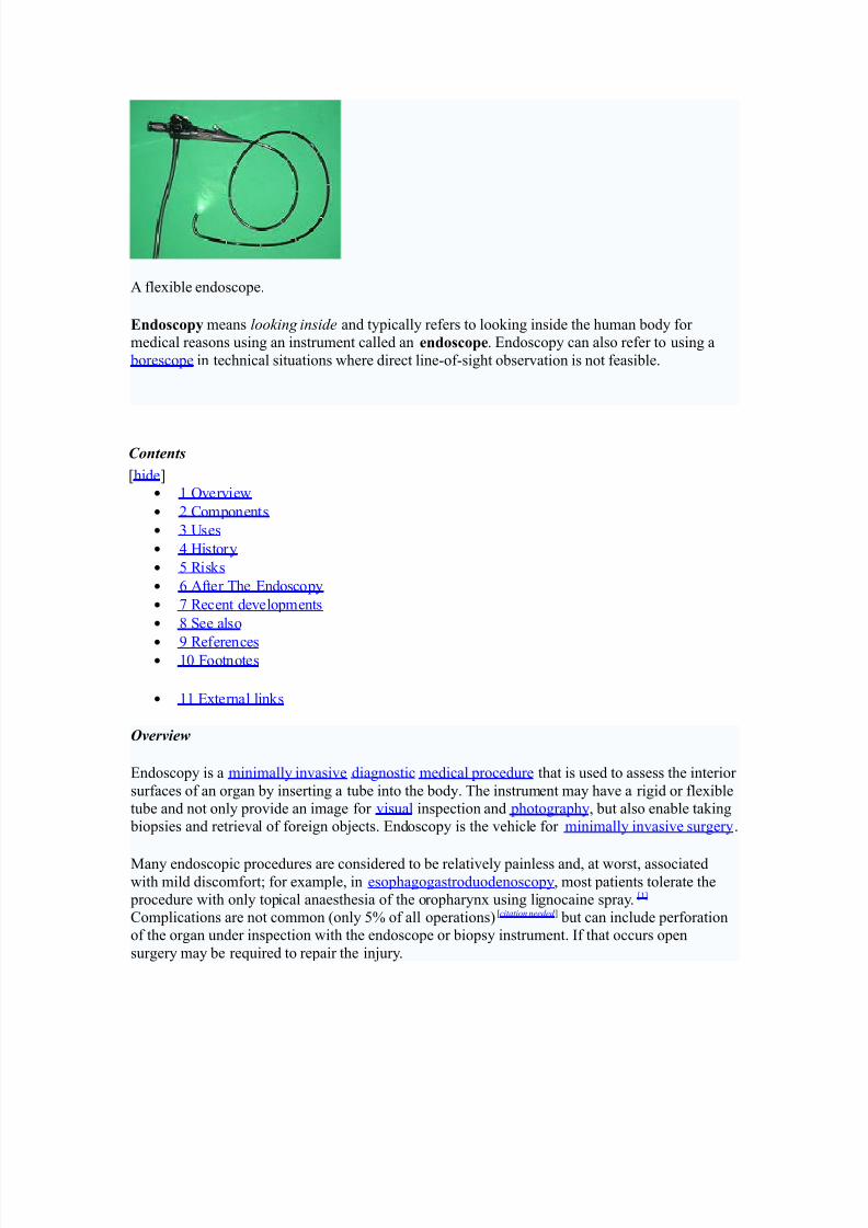
% flexible endosco&e.
Endoscoy means loo"ing inside and ty&ically refers to loo/ing inside the human body for
medical reasons using an instrument called an endoscoe. *ndosco&y can also refer to using a
boresco&e in technical situations where direct line!of!sight observation is not feasible.
Contents
[hide\
• 2 Overview
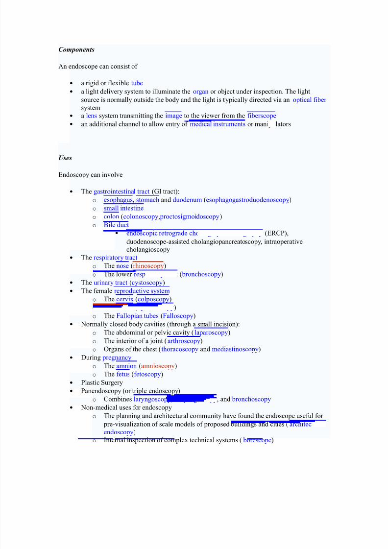
• 3 Com&onents
• ]ses
• = -istory
• F #is/s
• U %fter The *ndosco&y
• X #ecent develo&ments
• W ee also
• S #eferences • 2+ 4ootnotes
• 22 *xternal lin/s
*-er-iew
*ndosco&y is a minimally invasive diagnostic medical &rocedure that is used to assess the interior
surfaces of an organ by inserting a tube into the body. The instrument may have a rigid or flexible
tube and not only &rovide an image for visual ins&ection and &hotogra&hy, but also enable ta/ing
bio&sies and retrieval of foreign obDects. *ndosco&y is the vehicle for minimally invasive surgery.
1any endosco&ic &rocedures are considered to be relatively &ainless and, at worst, associatedwith mild discomfort6 for exam&le, in eso&hagogastroduodenosco&y, most &atients tolerate the
&rocedure with only to&ical anaesthesia of the oro&harynx using lignocaine s&ray.[2\
Com&lications are not common (only F of all o&erations"[citation needed \ but can include &erforation
of the organ under ins&ection with the endosco&e or bio&sy instrument. If that occurs o&en
surgery may be reuired to re&air the inDury.
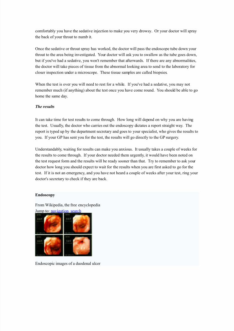
7/27/2019 Ec2021 Notes
http://slidepdf.com/reader/full/ec2021-notes 45/54
7/27/2019 Ec2021 Notes
http://slidepdf.com/reader/full/ec2021-notes 46/54
o *ndosco&es are also a tool hel&ful in the examination of im&rovised ex&losive
devices by bomb dis&osal &ersonnel.
o The 49I uses endosco&es for conducting surveillance via tight s&aces.
6istory
The first endosco&e, of a /ind, was develo&ed in 2W+U by hili& 9ozzini with his introduction of a
MichtleiterM (light conductor" Mfor the examinations of the canals and cavities of the human
bodyM. -owever, the ?ienna 1edical ociety disa&&roved of such curiosity. %n endosco&e was
first introduced into a human in 2W33 by 'illiam 9eaumont, an army surgeon at 1ac/inac Island,
1ichigan[citation needed \. The use of electric light was a maDor ste& in the im&rovement of endosco&y.The first such lights were external. ater, smaller bulbs became available ma/ing internal light
&ossible, for instance in a hysterosco&e by Charles 7avid in 2S+W[citation needed \. -ans Christian
acobaeus has been given credit for early endosco&ic ex&lorations of the abdomen and the thorax
with la&arosco&y (2S23" and thoracosco&y (2S2+"[citation needed \. a&arosco&y was used in thediagnosis of liver and gallbladder disease by -einz Lal/ in the 2S+s[citation needed \. -o&e re&orted in
2SX on the use of la&arosco&y to diagnose ecto&ic ®nancy[citation needed \. In 2S==, #aoul almer
&laced his &atients in the Trendelenburg &osition after gaseous distention of the abdomen and thus
was able to reliably &erform gynecologic la&arosco&y[citation needed \.
The first gastrocamera was released in 2SF+ by Olym&us O&tical Co., td. The device too/
&ictures on monochromatic film using a small light bulb that was triggered manually. The device
was of limited use, however, because it did not im&lement real!time o&tical ca&ability. Olym&us
continued its develo&ment of endosco&es by incor&orating fiber o&tics in the early 2SU+s, leading
to the first useful endosco&es. In 2SU=, it released a gastrocamera guided by a fibersco&e.[2\ %
few articles claim that 7r.9asil -irschowitz of ]niv.Of 1ichigan,%nn %rbor discussed the
endosco&e in early F+Ys.[3\
%s endosco&ic technology im&roved, so did the methods of gastrointestinal endosco&y. Owing &rimarily to the efforts of 7r. -iromi hinya in the late 2SU+s, $I endosco&y develo&ed into what
is more recognizable as todayYs colonosco&y. 'hile many doctors ex&erimented with techniues
to ta/e advantage of the new iterations of endosco&es, 7r. hinya focused on techniues that
would allow for successful o&eration of the endosco&e by an individual, reDecting the common
&ractice at the time of utilizing two &eo&le. Conseuently, many of the fundamental methods and
&rocedures of modern colonosco&y were develo&ed by 7r. hinya.
7r. hinyaYs other great contribution was to thera&eutic endosco&y, in his invention of the
electrosurgical &oly&ectomy snare with the aid of Olym&us em&loyee -iroshi Ichi/awa. hinya
s/etched his first &lans for the device on anuary W, 2SUS. -e envisioned a loo& of wire attached
to the end of a colonosco&e that would allow for easy removal of &oly&s during investigation by
&assing a current through the wire. 9y e&tember of 2SUS, the first &oly&ectomy using this device
was &erformed. oly&ectomy has since become the most common thera&eutic &rocedure
&erformed with an endosco&e. (iva/ 3++="
9y 2SW+, la&arosco&y training was reuired by gynecologists to &erform tubal ligation &rocedures
and diagnostic evaluations of the &elvis. The first la&arosco&ic cholecystectomy was &erformed in
2SW= and the first video!la&arosco&ic cholecystectomy in 2SWX[citation needed \. 7uring the 2SS+s,
la&arosco&ic surgery was extended to the a&&endix, s&leen, colon, stomach, /idney, and
liver [citation needed \. 'ireless ca&sule endosco&y or Ca&sule *ndosco&y is now a&&roved in all the
countries including a&an where government reimbusement will be available from
7/27/2019 Ec2021 Notes
http://slidepdf.com/reader/full/ec2021-notes 47/54
Oct.3++X.Ca&sule *ndosco&y [\ increases detection of mall 9owel tumors where traditional
*ndosco&y is not very efficient.
Risks
• Infection
• unctured organs
• %llergic reactions due to Contrast agents or dyes (such as those used in a CT scan"
• Over!sedation
#fter The Endoscopy
%fter the &rocedure the &atient will be observed and monitored by a ualified individual in the
endosco&y or a recovery area until a significant &ortion of the medication has worn off.
Occasionally a &atient is left with a mild sore throat, which &rom&tly res&onds to saline gargles,
or a feeling of distention from the insufflated air that was used during the &rocedure. 9oth
&roblems are mild and fleeting. 'hen fully recovered, the &atient will be instructed when to
resume his0her usual diet (&robably within a few hours" and will be allowed to be ta/en home.
9ecause of the use of sedation, most facilities mandate that the &atient is ta/en home by another &erson and not to drive on his0her own or handle machinery for the remainder of the day.
Recent de-elopments
'ith the a&&lication of robotic systems, telesurgery was introduced as the surgeon could o&erate
from a site &hysically removed from the &atient. The first transatlantic surgery has been called the
indbergh O&eration.
7/27/2019 Ec2021 Notes
http://slidepdf.com/reader/full/ec2021-notes 48/54
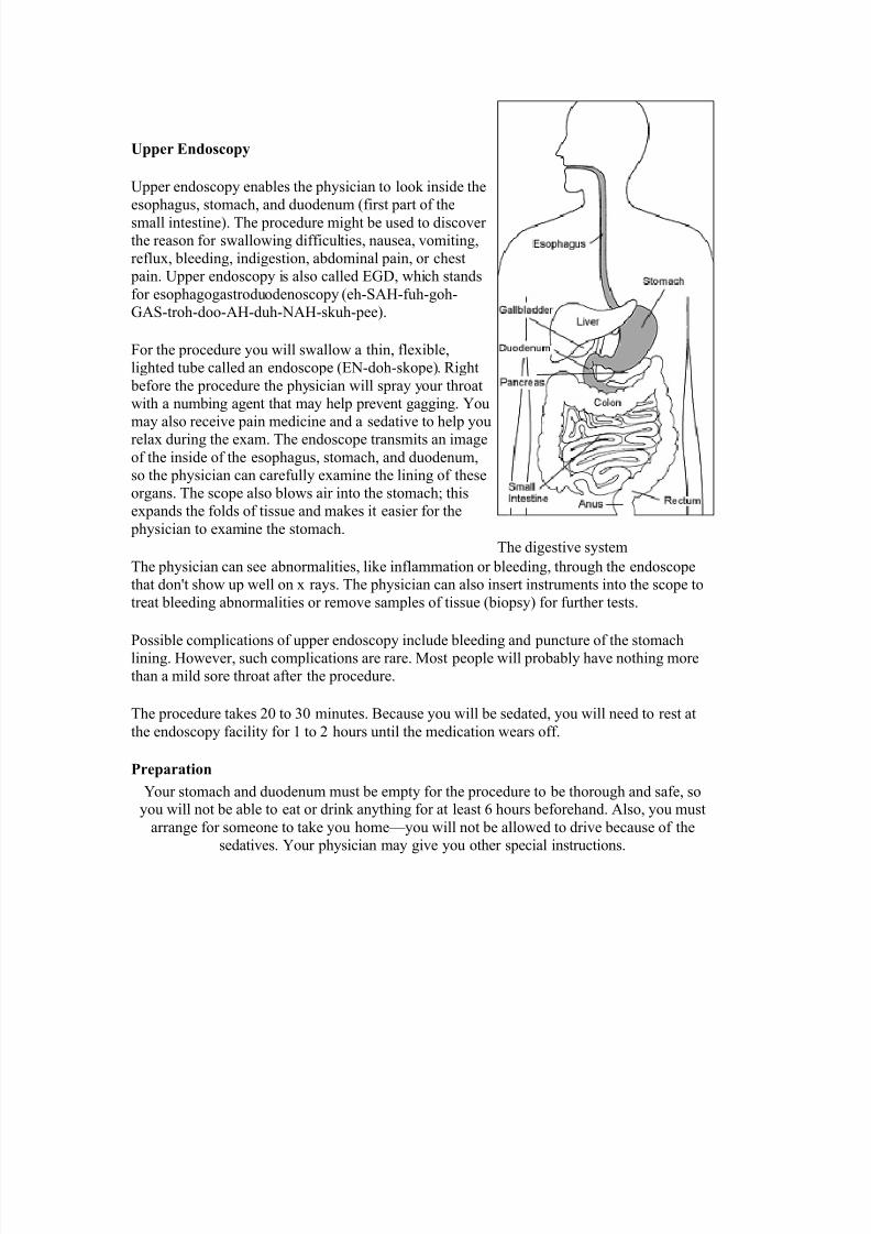
er Endoscoy
]&&er endosco&y enables the &hysician to loo/ inside the
eso&hagus, stomach, and duodenum (first &art of the
small intestine". The &rocedure might be used to discover
the reason for swallowing difficulties, nausea, vomiting,
reflux, bleeding, indigestion, abdominal &ain, or chest
&ain. ]&&er endosco&y is also called *$7, which stands
for eso&hagogastroduodenosco&y (eh!%-!fuh!goh!
$%!troh!doo!%-!duh!)%-!s/uh!&ee".
4or the &rocedure you will swallow a thin, flexible,
lighted tube called an endosco&e (*)!doh!s/o&e". #ight
before the &rocedure the &hysician will s&ray your throat
with a numbing agent that may hel& &revent gagging. >ou
may also receive &ain medicine and a sedative to hel& you
relax during the exam. The endosco&e transmits an image
of the inside of the eso&hagus, stomach, and duodenum,
so the &hysician can carefully examine the lining of these
organs. The sco&e also blows air into the stomach6 this
ex&ands the folds of tissue and ma/es it easier for the
&hysician to examine the stomach.
The &hysician can see abnormalities, li/e inflammation or bleeding, through the endosco&e
that donYt show u& well on x rays. The &hysician can also insert instruments into the sco&e to
treat bleeding abnormalities or remove sam&les of tissue (bio&sy" for further tests.
ossible com&lications of u&&er endosco&y include bleeding and &uncture of the stomach
lining. -owever, such com&lications are rare. 1ost &eo&le will &robably have nothing more
than a mild sore throat after the &rocedure.
The &rocedure ta/es 3+ to + minutes. 9ecause you will be sedated, you will need to rest at
the endosco&y facility for 2 to 3 hours until the medication wears off.
Prearation
>our stomach and duodenum must be em&ty for the &rocedure to be thorough and safe, soyou will not be able to eat or drin/ anything for at least U hours beforehand. %lso, you must
arrange for someone to ta/e you home^you will not be allowed to drive because of the
sedatives. >our &hysician may give you other s&ecial instructions.
The digestive system
7/27/2019 Ec2021 Notes
http://slidepdf.com/reader/full/ec2021-notes 49/54
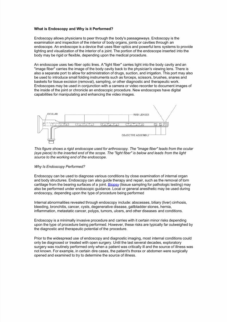
What is Endoscopy and Why is it Performed?
Endoscopy allows physicians to peer through the body's passageways. Endoscopy is theexamination and inspection of the interior of body organs, joints or cavities through anendoscope. An endoscope is a device that uses fiber optics and powerful lens systems to providelighting and visualization of the interior of a joint. he portion of the endoscope inserted into the
body may be rigid or flexible, depending upon the medical procedure.
An endoscope uses two fiber optic lines. A !light fiber! carries light into the body cavity and an!image fiber! carries the image of the body cavity bac" to the physician's viewing lens. here isalso a separate port to allow for administration of drugs, suction, and irrigation. his port may alsobe used to introduce small folding instruments such as forceps, scissors, brushes, snares andbas"ets for tissue excision #removal$, sampling, or other diagnostic and therapeutic wor".Endoscopes may be used in conjunction with a camera or video recorder to document images ofthe inside of the joint or chronicle an endoscopic procedure. %ew endoscopes have digitalcapabilities for manipulating and enhancing the video images.
This figure shows a rigid endoscope used for arthroscopy. The "image fiber" leads from the ocular (eye piece) to the inserted end of the scope. The "light fiber" is below and leads from the lightsource to the working end of the endoscope.
Why Is Endoscopy Performed
Endoscopy can be used to diagnose various conditions by close examination of internal organand body structures. Endoscopy can also guide therapy and repair, such as the removal of torncartilage from the bearing surfaces of a joint. &iopsy #tissue sampling for pathologic testing$ mayalso be performed under endoscopic guidance. ocal or general anesthetic may be used duringendoscopy, depending upon the type of procedure being performed
(nternal abnormalities revealed through endoscopy include) abscesses, biliary #liver$ cirrhosis,bleeding, bronchitis, cancer, cysts, degenerative disease, gallbladder stones, hernia,inflammation, metastatic cancer, polyps, tumors, ulcers, and other diseases and conditions.
Endoscopy is a minimally invasive procedure and carries with it certain minor ris"s depending
upon the type of procedure being performed. *owever, these ris"s are typically far outweighed bythe diagnostic and therapeutic potential of the procedure.
+rior to the widespread use of endoscopy and diagnostic imaging, most internal conditions couldonly be diagnosed or treated with open surgery. ntil the last several decades, exploratorysurgery was routinely performed only when a patient was critically ill and the source of illness wasnot "nown. -or example, in certain dire cases, the patient's thorax or abdomen were surgicallyopened and examined to try to determine the source of illness.
7/27/2019 Ec2021 Notes
http://slidepdf.com/reader/full/ec2021-notes 50/54
Endoscopy can often be done on an outpatient basis. !utpatient! means that the proceduredoes not re/uire hospital admission and acute care and observation and may be performedoutside the premises of a hospital. utpatient procedures performed at hospitals or ambulatorycenters allow the patient to go home or return to wor" within a short while after their procedure.
Types of Endoscopy
-iber optic endoscopes now have widespread use in medicine and guide a myriad of diagnosticand therapeutic procedures including)
• Arthroscopy: examination of joints for diagnosis and treatment #arthroscopic surgery$
• Bronchoscopy: examination of the trachea and lung's bronchial trees to reveal
abscesses, bronchitis, carcinoma, tumors, tuberculosis, alveolitis, infection, inflammation
• Colonoscopy: examination of the inside of the colon and large intestine to detect polyps,
tumors, ulceration, inflammation, colitis diverticula, 0hrohn's disease, and discovery andremoval of foreign bodies.
• Colposcopy: direct visualization of the vagina and cervix to detect cancer, inflammation,
and other conditions.
• Cystoscopy: examination of the bladder, urethra, urinary tract, uteral orifices, and
prostate #men$ with insertion of the endoscope through the urethra.
ERCP (endoscopic retrograde cholangio-pancreatography) uses endoscopic guidance toplace a catheter for x1ray fluorosocopy with contrast enhancement. his techni/ue is used toexamine the liver's biliary tree, the gallbladder, the pancreatic duct and other anatomy to chec"for stones, other obstructions and disease. 21ray contrast is introduced into these ducts viacatheter and fluoroscopic x1ray images are ta"en to show any abnormality or bloc"age. (f diseaseis detected, it can sometimes be treated at the same time or biopsy can be performed to test forcancer or other pathology. E30+ can detect biliary cirrhosis,.
• cancer of the bile ducts, pancreatic cysts, pseudocysts, pancreatic tumors, chronic
pancreatitis and other conditions such as gallbladder stones.
• E! (Esophogealgastrod"odensoscopy): visual examination of the upper gastro1intestinal #4($ tract. #also referred to as gastroscopy$ to reveal hemorrhage, hiatal hernia,inflammation of the esophagus, gastric ulcers.
• Endoscopic #iopsy is the removal of tissue specimens for pathologic examination and
analysis.
• astroscopy: examination of the lining of the esophagus, stomach, and duodenum.
4astroscopy is often used to diagnose ulcers and other sources of bleeding and to guidebiopsy of suspect 4( cancers.
• $aparoscopy: visualization of the stomach, liver and other abdominal organs including
the female reproductive organs, for example, the fallopian tubes.
• $aryngoscopy: examination of the larynx #voice box$.
• Proctoscopy% sigmoidoscopy, proctosigmoidoscopy) examination of the rectum and
sigmoid colon.
• Thoracoscopy: examination of the pleura #sac that covers the lungs$, pleural spaces,
mediastinum, and pericardium.
A Brief &istory of Endoscopy
(n the early 5677s, the first attempts to view inside the body with lighted telescopes were made.hese initial devices were often fully rigid. (n the 5687s, semi1flexible endoscopes calledgastroscopes were developed to view inside of the stomach. -iber1optic endoscopy was
7/27/2019 Ec2021 Notes
http://slidepdf.com/reader/full/ec2021-notes 51/54
pioneered by 9outh African1born physician &asil *irschowitz at the niversity of :ichigan in56;<. =idespread use of fiber optic endoscopes began in the 56>7s.
A fiber optic cable is simply a bundle of microscopic glass or plastic fibers that literally allows lightand images to be transmitted through curved structures. -iber optic cables are also replacingmetal wires as the bac"bone of the world's telecommunications infrastructure. his (nternet page
may have traveled through a fiber optic cable as a stream of digital data #bursts of light$ on itsway to your computer
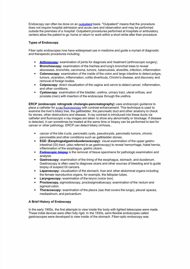
Endoscoy Equi"ent
Endoscopes have many practical needs. And *.:.&. Endoscopy +roducts #*ollywood, -lorida$has been providing endoscopic e/uipment and educating people on the use of endoscopes for
more than 5< years. &e sure to &rowse our 0atalog for all the details on how to purchase thesemedical instruments that can examine any part of the body.
%ideo
#ystems
Fi&er
Endoscope
s
%ideo
Endoscope
s
(n the simplest terms, Endoscopy e/uipment consists of instruments that can loo" at the inside of many different organs ? these are small, flexible or rigid tubes with a light or lenses on the endthat can loo" into the esophagus, stomach and colon ? and in more general terms endoscopye/uipment can help doctors loo" deep inside body structures and hollow organs.
An endoscope and related endoscope products and e/uipment are usually composed of threecomponents)
• An optic system that allows the doctor to loo" through the scope into the organ or cavity,
or to attach a video camera to the scope
• A fi#eroptic ca#le to light up the bodily area
• A l"men #e.g. the bore of a tube, li"e a needle or catheter$ to ta"e tissue samples of the
area being viewed
he beauty of endoscopic products is that they perform dual functions ? with both diagnostic andtherapeutic capabilities. -or example, this means that these endoscopic products and instrumentscan perform biopsies #e.g. to evaluate tissue samples$ as well as provide sclerotherapy #amedical procedure used to treat varicose veins and @spider veins$. (n truth, these brief explanations only tell part of the story.
7/27/2019 Ec2021 Notes
http://slidepdf.com/reader/full/ec2021-notes 52/54
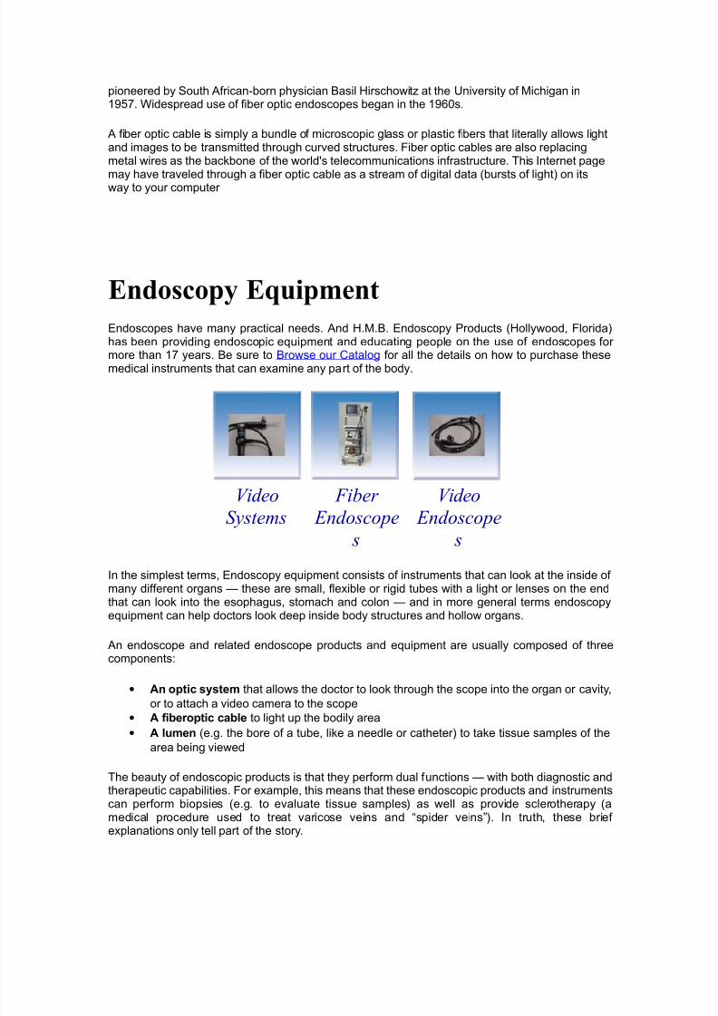
TYPES OF ENDOSCOPES
a"e a loo" at the different types of endoscopic e/uipment you can get with *.:.&. Endoscopy+roducts. Again, in very general terms, there are two main types of endoscopes)
Rigid Flexi&le5. rigid endoscopes B the majority of which use a convex #curving out, li"e one half of a
circle$ glass lens system, in which the small glass lenses are separated by large air spaces.
C. fle'i#le endoscopes allow for just that ? flexibility. (n the animal "ingdom, for example,a flexible endoscope would be perfect for examining the stomach area of a sna"e.
he popularity of endoscopy e/uipment continues to grow. 9ome of the industryDs householdnames include lympus, +entax, -unjinon and 9torz ? with *.:.&. both selling and repairingpre1owned and completely refurbished endoscopic products from each of these major manufacturers. &rowse our 0atalog to get the ones you need
=HE&M9G&PHPPLIC=I9N' Thermogra&hs are digital recording thermometers used to logtem&erature in the
marine environment. The instruments are attached to a com&uter to set u& recording
&arameters for de&loyment, downloading, and dis&lay of data in gra&hic or numeric format. These units
are &laced in
underwater housings and attached to the bottom or sus&ended in the water column for
de&loyment.
/E)C&IP=I9N' Two ty&es of thermogra&h are currently available. The #yan
Tem&mentor is a
reusable data logger that allows storage of a maximum of U,U2 tem&eraturemeasurements in the
range of !3°C to X+°C with +.2° resolution and +.° accuracy. The instrument can be
&rogrammedto ta/e measurements from once &er second to once every other hour. Instrument
dimensions are K x
UK x 2.K and the unit weighs 22 ounces. The -obo Tem& is a miniature, reusable data
logger that
allows storage of 2,W++ measurements in the range of !3+°C to X+°C with
+.° resolution and +.X°
accuracy. am&ling intervals from +.F seconds to =.W hours are available. Instrument
dimensions are
7/27/2019 Ec2021 Notes
http://slidepdf.com/reader/full/ec2021-notes 53/54
3.=K x 2.SK x +.WK and the unit weighs 2 ounce. 9oth units are battery &owered with the
battery life of
the Tem&mentor being a&&roximately two years and the battery life of the -obo Tem&
being one year. =HE&M9G&PHPPLIC=I9N' Thermogra&hs are digital recording thermometers used to log
tem&erature in themarine environment. The instruments are attached to a com&uter to set u& recording &arameters for
de&loyment, downloading, and dis&lay of data in gra&hic or numeric format. These units
are &laced in
underwater housings and attached to the bottom or sus&ended in the water column forde&loyment.
/E)C&IP=I9N' Two ty&es of thermogra&h are currently available. The #yan
Tem&mentor is areusable data logger that allows storage of a maximum of U,U2 tem&erature
measurements in the
range of !3°C to X+°C with +.2° resolution and +.° accuracy. The instrument can be &rogrammedto ta/e measurements from once &er second to once every other hour. Instrument
dimensions are K x
UK x 2.K and the unit weighs 22 ounces. The -obo Tem& is a miniature, reusable datalogger that
allows storage of 2,W++ measurements in the range of !3+°C to X+°C with
+.° resolution and +.X°
accuracy. am&ling intervals from +.F seconds to =.W hours are available. Instrumentdimensions are
3.=K x 2.SK x +.WK and the unit weighs 2 ounce. 9oth units are battery &owered with the
battery life of the Tem&mentor being a&&roximately two years and the battery life of the -obo Tem&
being one year. =HE&M9G&PHPPLIC=I9N' Thermogra&hs are digital recording thermometers used to log
tem&erature in the
marine environment. The instruments are attached to a com&uter to set u& recording &arameters for
de&loyment, downloading, and dis&lay of data in gra&hic or numeric format. These units
are &laced in
underwater housings and attached to the bottom or sus&ended in the water column forde&loyment.
/E)C&IP=I9N' Two ty&es of thermogra&h are currently available. The #yanTem&mentor is areusable data logger that allows storage of a maximum of U,U2 tem&erature
measurements in the
range of !3°C to X+°C with +.2° resolution and +.° accuracy. The instrument can be
&rogrammedto ta/e measurements from once &er second to once every other hour. Instrument
dimensions are K x
7/27/2019 Ec2021 Notes
http://slidepdf.com/reader/full/ec2021-notes 54/54
UK x 2.K and the unit weighs 22 ounces. The -obo Tem& is a miniature, reusable data
logger that
allows storage of 2,W++ measurements in the range of !3+°C to X+°C with
+.° resolution and +.X°
accuracy. am&ling intervals from +.F seconds to =.W hours are available. Instrument
dimensions are3.=K x 2.SK x +.WK and the unit weighs 2 ounce. 9oth units are battery &owered with the battery life of
the Tem&mentor being a&&roximately two years and the battery life of the -obo Tem&
being one year.


![notes NOTES ]” BACKGROUND](https://img.pdfslide.net/doc/110x75/61bd44c661276e740b111621/notes-notes-background.jpg)