Embed Size (px)
Citation preview

ECE532: EMG Controlled Video Game Group Report
Jamie Liu
Lian Ni
Michael Ferri

Table of Contents
1. Overview ........................................................................................................................... Pg. 1
1.1. Background ................................................................................................................ Pg. 1
1.2. Motivation .................................................................................................................. Pg. 2
1.3. Goals .......................................................................................................................... Pg. 2
1.4. System Changes ......................................................................................................... Pg. 3
1.5. System Block Diagram .............................................................................................. Pg. 4
1.6. Brief Description of IP ............................................................................................... Pg. 5
2. Outcome ............................................................................................................................ Pg. 8
2.1. Results........................................................................................................................ Pg. 8
2.2. Future Work ............................................................................................................... Pg. 8
3. Detailed Description of IP Blocks .................................................................................... Pg. 9
3.1. EMG Electrodes ......................................................................................................... Pg. 9
3.2. Sensors ....................................................................................................................... Pg. 10
3.3. Analog Processor ....................................................................................................... Pg. 10
3.4. Analog to Digital Converter & adc_data_reader ....................................................... Pg. 14
3.5. uB_input .................................................................................................................... Pg. 17
3.6. uB_game .................................................................................................................... Pg. 22
3.7. uB_video .................................................................................................................... Pg. 23
3.8. GPIOs & audio_core_0 .............................................................................................. Pg. 25
3.9. video_out ................................................................................................................... Pg. 25
3.10. fsl_v20...................................................................................................................... Pg. 26
3.11. clock_generator ........................................................................................................ Pg. 27
4. Design Tree Description ................................................................................................... Pg. 28
5. Reference .......................................................................................................................... Pg. 30

1
1. Overview
1.1. Background
Electricity in biological tissue has been a fascination since the discovery of electricity producing
muscle found in the electric ray fish by Francesco Redi in 1666. The interest in both the
scientific community and the world in general has since been compounded by subsequent
discoveries and experimentation such as Galvani's experiments in 1792 which showed that
electricity could initiate muscle contractions in dead tissue inspiring the creation of the fictional
character Frankenstein's monster and the discovery by Dubois-Raymond in 1849 that it was also
possible to record electrical activity during voluntary muscle contraction which lead to the
creation of electromyography (EMG) as we know it today. Now, decades after the first EMG
recording by Marey in 1890, muscular bioelectricity is still a hot topic of study that is full of
potential due to the unique opportunity to directly connect living tissue and systems to non-living
systems of our creation.
Currently EMG signals are used in a variety of clinical and biomedical application. The oldest
and most well studied use of the EMG is in diagnostics; it is used as a diagnostic tool for
assessing a variety of neuromuscular disease, low back pain and disorders of motor control [1].
As a diagnostic and analysis tool the EMG is also used to study human movement in order to
identify and monitor abnormal movement patterns allowing for management or treatment of
motor disability through surgical or other correctional techniques [2]. More recently, EMG
signals have been used as a control signal for advanced prosthetic devices most notably in hand
and arm prosthetics particularly with the successful creation of the MANUS-HAND in 2004[3]
and a multiple joint whole arm system created by T. Kuiken et. al in 2009 [4]. Related to
prosthetics and one of the main motivations for our project is the rehabilitation of patients with
disturbed neuromotor control using EMG feedback therapy.
EMG feedback therapy helps patients regain function of paralyzed muscles or limbs. The target
of rehabilitation is patients who exhibit some residual volitional motor activity which is
insufficient for adequate motor function. The theoretical premise of EMG feedback therapy is
that due to neuroplasticity (ability for the brain to change or remap as a result of experiences and
reinforcement) and the existence of alternate pathways for each muscle function muscles
controlled by damaged pathways can be activated and eventually completely controlled by the
undamaged alternate pathways [5]. In EMG feedback therapy the patient is asked to attempt
movement the EMG electrodes monitoring the muscle or muscle group will detect even the
slightest electrical activity [5]. When desired activity is detected the patient is given auditory or
visual clues that they have activated a neuromuscular pathway that can be recruited to replace the
damaged pathway [5]. With repeated exercise and practice the alternate pathways recruited will
strengthen and eventually assume the function of the damaged pathway [5].
2
1.2. Motivation
The main inspiration for our project stems from the idea of providing audio and visual feedback
based on EMG signals during training. Rehabilitation is typically a long and arduous process, but
if feedback can be given in the form of entertainment it could help increase patient morale. A
game calibrated to monitor target muscle functions would allow patients the ability to exercise,
strengthening the desired pathways, in a more enjoyable environment.
1.3. Goals
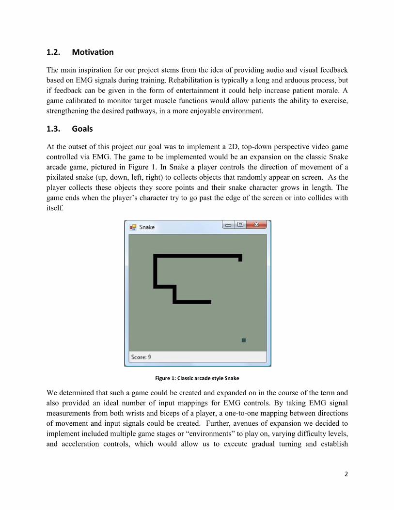
At the outset of this project our goal was to implement a 2D, top-down perspective video game
controlled via EMG. The game to be implemented would be an expansion on the classic Snake
arcade game, pictured in Figure 1. In Snake a player controls the direction of movement of a
pixilated snake (up, down, left, right) to collects objects that randomly appear on screen. As the
player collects these objects they score points and their snake character grows in length. The
game ends when the player’s character try to go past the edge of the screen or into collides with
itself.
Figure 1: Classic arcade style Snake
We determined that such a game could be created and expanded on in the course of the term and
also provided an ideal number of input mappings for EMG controls. By taking EMG signal
measurements from both wrists and biceps of a player, a one-to-one mapping between directions
of movement and input signals could be created. Further, avenues of expansion we decided to
implement included multiple game stages or “environments” to play on, varying difficulty levels,
and acceleration controls, which would allow us to execute gradual turning and establish

3
complete free range of character motion. The focus of these expansions was to introduce
elements of variability in game play to promote the game’s replay value.
1.4. System Changes
During the course of the project three major adjustments were made to the original design
proposal.
1. Introduction of multiplayer
Instead of having artificially increasing levels of difficulty, in the form of more
challenging enemies or obstructive obstacles as the player progressed, it was decided that
having players compete against each other would be a more enjoyable challenge.
Multiplayer allows the difficulty to naturally increase as competitors improve.
2. Re-mapping of player controls
At the cost of including multiplayer into the game, we elected to reduce the number of
inputs per user to two, to greatly reduce the complexity and cost of the input circuit.
Now EMG signals are measured from each player’s biceps and control whether the snake
turns left or right.
3. Processor Functionality Changes
Originally it was thought to be possible to completely separate the video game update
logic from the video game draw logic and run them concurrently on two separate
processors. Ideally the video game logic would only handle information about the game
state and make calculations to determine the progression of the game state, while the
draw logic continuously updates the video display based on the current game state.
However, we found that due to the low level graphical nature of the game, the game logic
was too tightly coupled to information in video memory. As such it was determined that
to avoid constant bi-direction communication between a game and video processor, we
decided to give each processor the ability to manipulate only certain parts of video
memory each. The game processor deals with the center “game area”, where the players’
characters moved and where most of the game logic applies. The designated video
processor reads the players’ scores from memory and updates the sides the video display
accordingly.
4
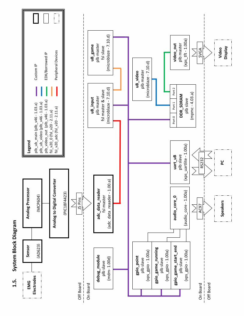
1.5
. S
yst
em
Blo
ck D
iag
ram
On
Bo
ard
Off
Bo
ard
PC
Off
Bo
ard
On
Bo
ard
au
dio
_co
re_
0
(au
dio
_co
re -
1.0
0a
)
Sp
ea
ke
rs
gp
io_
ga
me
_ru
nn
ing
plb
sla
ve
(xp
s_g
pio
- 1
.00
a)
gp
io_
ga
me
_st
art
_e
nd
plb
sla
ve
(xp
s_g
pio
- 1
.00
a)
gp
io_
po
int
plb
sla
ve
(xp
s_g
pio
- 1
.00
a)
de
bu
g_
mo
du
le
plb
sla
ve
(md
m-
1.0
0d
)
ua
rt_
uB
plb
sla
ve
(xp
s_u
art
lite
- 1
.00
a)
uB
_in
pu
t
plb
ma
ste
r
fsl
ma
ste
r &
sla
ve
(mic
rob
laze
- 7
.10
.d)
uB
_g
am
e
plb
ma
ste
r
fsl
sla
ve
(mic
rob
laze
- 7
.10
.d)
vid
eo
_o
ut
plb
ma
ste
r
(xp
s_tf
t -
1.0
0a
)
Vid
eo
Dis
pla
y
uB
_v
ide
o
plb
ma
ste
r
(mic
rob
laze
- 7
.10
.d)
DD
R_
SD
RA
M
plb
sla
ve
(mp
mc
- 4
.03
.a)
Po
rt 0
P
ort
1
Po
rt 2
AC
97
S
VG
A
J5 P
ins
ad
c_d
ata
_re
ad
er
fsl
ma
ste
r
(ad
c_d
ata
_re
aa
de
r -
1.0
0.a
)
EM
G
Ele
ctro
de
s
Se
nso
r
(AD
62
3)
An
alo
g P
roce
sso
r
(MC
P6
04
)
An
alo
g t
o D
igit
al
Co
nv
ert
er
(PIC
18
F4
42
3)
Leg
en
d
Cu
sto
m I
P
ED
K/B
orr
ow
ed
IP
Pe
rip
he
ral
De
vice
s
plb
_u
b_
ma
in (
plb
_v4
6 -
1.0
3.a
)
plb
_u
b_
vid
eo
(p
lb_
v46
- 1
.03
.a)
plb
_vi
de
o_
ou
t (
plb
_v4
6 -
1.0
3.a
)
fsl_
v2
0_
0 (
fsl_
v20
- 2
.11
.a)
fsl_
v2
0_
ad
c (f
sl_
v20
- 2
.11
.a)
RS
23
2
5
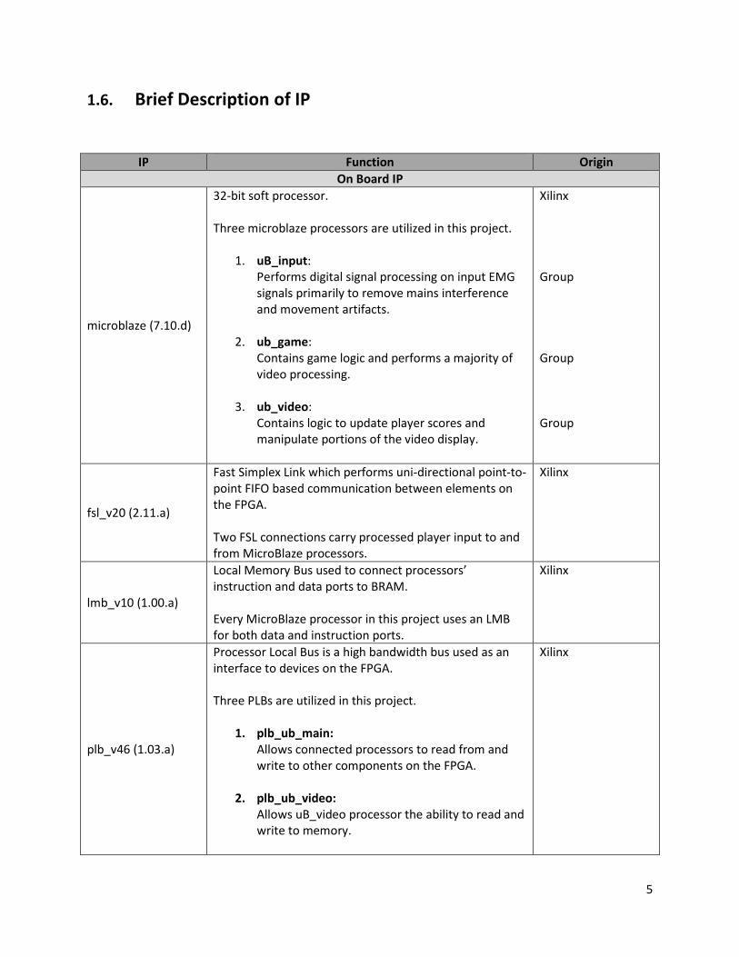
1.6. Brief Description of IP
IP Function Origin
On Board IP
microblaze (7.10.d)
32-bit soft processor.
Three microblaze processors are utilized in this project.
1. uB_input:
Performs digital signal processing on input EMG
signals primarily to remove mains interference
and movement artifacts.
2. ub_game:
Contains game logic and performs a majority of
video processing.
3. ub_video:
Contains logic to update player scores and
manipulate portions of the video display.
Xilinx
Group
Group
Group
fsl_v20 (2.11.a)
Fast Simplex Link which performs uni-directional point-to-
point FIFO based communication between elements on
the FPGA.
Two FSL connections carry processed player input to and
from MicroBlaze processors.
Xilinx
lmb_v10 (1.00.a)
Local Memory Bus used to connect processors’
instruction and data ports to BRAM.
Every MicroBlaze processor in this project uses an LMB
for both data and instruction ports.
Xilinx
plb_v46 (1.03.a)
Processor Local Bus is a high bandwidth bus used as an
interface to devices on the FPGA.
Three PLBs are utilized in this project.
1. plb_ub_main:
Allows connected processors to read from and
write to other components on the FPGA.
2. plb_ub_video:
Allows uB_video processor the ability to read and
write to memory.
Xilinx
6
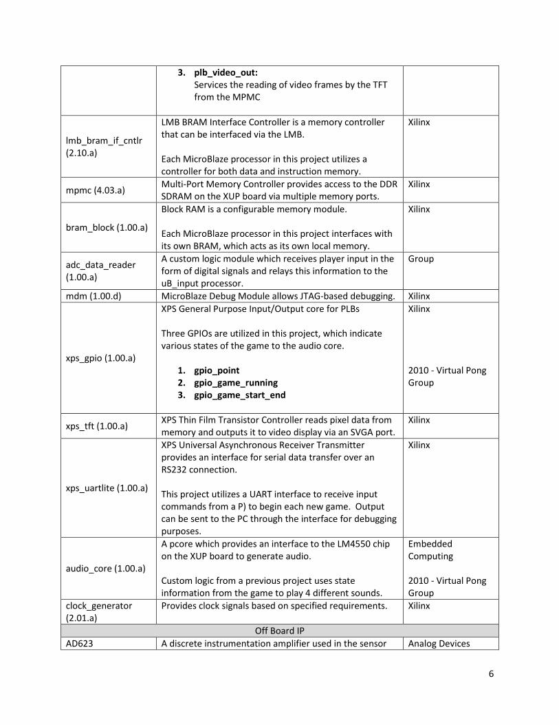
3. plb_video_out:
Services the reading of video frames by the TFT
from the MPMC
lmb_bram_if_cntlr
(2.10.a)
LMB BRAM Interface Controller is a memory controller
that can be interfaced via the LMB.
Each MicroBlaze processor in this project utilizes a
controller for both data and instruction memory.
Xilinx
mpmc (4.03.a) Multi-Port Memory Controller provides access to the DDR
SDRAM on the XUP board via multiple memory ports.
Xilinx
bram_block (1.00.a)
Block RAM is a configurable memory module.
Each MicroBlaze processor in this project interfaces with
its own BRAM, which acts as its own local memory.
Xilinx
adc_data_reader
(1.00.a)
A custom logic module which receives player input in the
form of digital signals and relays this information to the
uB_input processor.
Group
mdm (1.00.d) MicroBlaze Debug Module allows JTAG-based debugging. Xilinx
xps_gpio (1.00.a)
XPS General Purpose Input/Output core for PLBs
Three GPIOs are utilized in this project, which indicate
various states of the game to the audio core.
1. gpio_point
2. gpio_game_running
3. gpio_game_start_end
Xilinx
2010 - Virtual Pong
Group
xps_tft (1.00.a) XPS Thin Film Transistor Controller reads pixel data from
memory and outputs it to video display via an SVGA port.
Xilinx
xps_uartlite (1.00.a)
XPS Universal Asynchronous Receiver Transmitter
provides an interface for serial data transfer over an
RS232 connection.
This project utilizes a UART interface to receive input
commands from a P) to begin each new game. Output
can be sent to the PC through the interface for debugging
purposes.
Xilinx
audio_core (1.00.a)
A pcore which provides an interface to the LM4550 chip
on the XUP board to generate audio.
Custom logic from a previous project uses state
information from the game to play 4 different sounds.
Embedded
Computing
2010 - Virtual Pong
Group
clock_generator
(2.01.a)
Provides clock signals based on specified requirements. Xilinx
Off Board IP
AD623 A discrete instrumentation amplifier used in the sensor Analog Devices
7
components.
LM4040 Provides a 2.5V reference voltage. National
Semiconductor
MCP604
Quad op-amp IC used to buffer the reference voltage for
each input signal and perform low-pass filtering for
proper analog to digital conversion.
Microchip
PIC18F4423
PIC Microcontroller to sample all four input signals.
Custom logic performs analog to digital conversion of
input signal.
Microchip
Group
Peripheral Devices
EMG Electrodes Surface recording electrodes to measure electromyogram
signals as player input.
Rhymlink
International
Speakers
Receive and play audio signals from the FPGA
corresponding to events that occur while the game is
being played.
Group
Video Display Where all game elements are displayed. Group
PC
Connects to the FPGA via UART interface. Provides input
to start a game and receives output for debugging
purposes.
Group
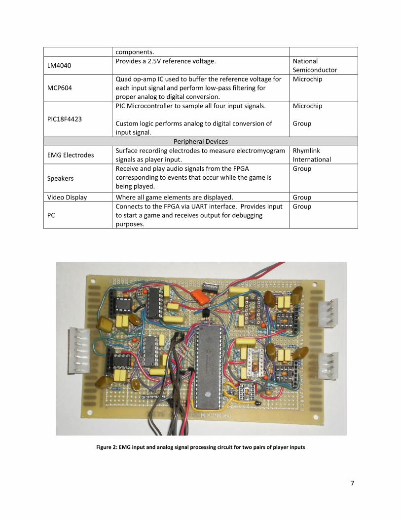
Figure 2: EMG input and analog signal processing circuit for two pairs of player inputs
8
2. Project Outcome
2.1. Results
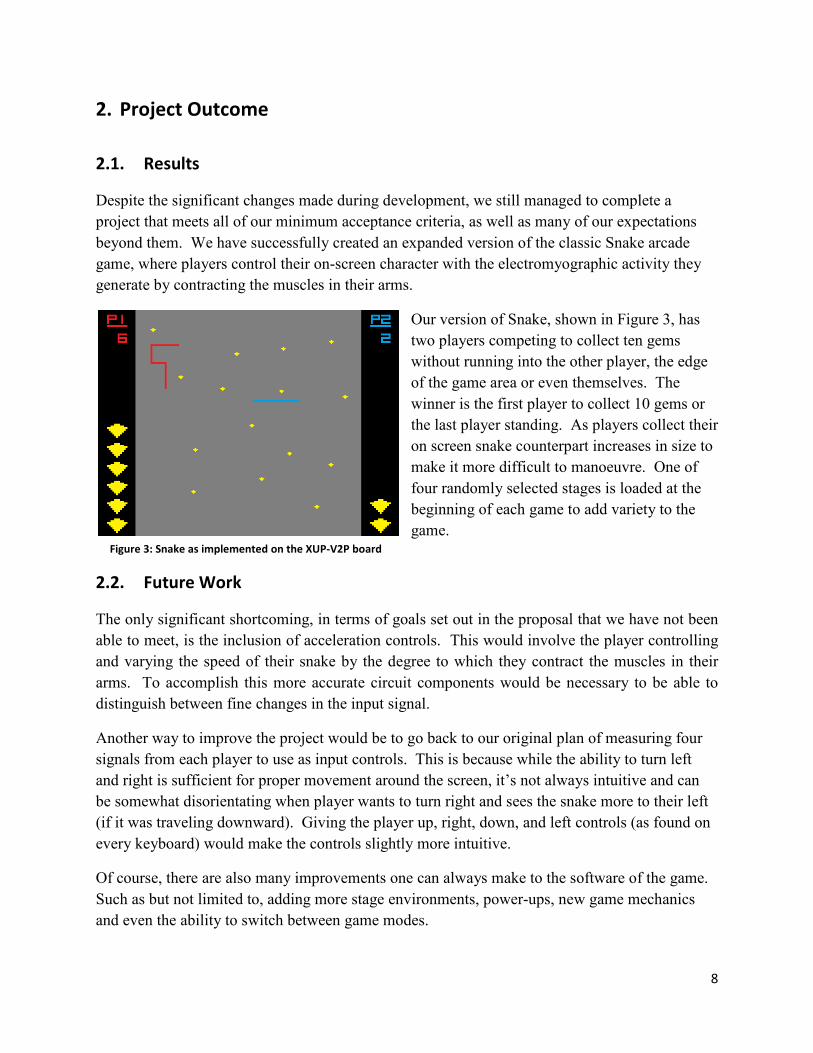
Despite the significant changes made during development, we still managed to complete a
project that meets all of our minimum acceptance criteria, as well as many of our expectations
beyond them. We have successfully created an expanded version of the classic Snake arcade
game, where players control their on-screen character with the electromyographic activity they
generate by contracting the muscles in their arms.
Our version of Snake, shown in Figure 3, has
two players competing to collect ten gems
without running into the other player, the edge
of the game area or even themselves. The
winner is the first player to collect 10 gems or
the last player standing. As players collect their
on screen snake counterpart increases in size to
make it more difficult to manoeuvre. One of
four randomly selected stages is loaded at the
beginning of each game to add variety to the
game.
2.2. Future Work
The only significant shortcoming, in terms of goals set out in the proposal that we have not been
able to meet, is the inclusion of acceleration controls. This would involve the player controlling
and varying the speed of their snake by the degree to which they contract the muscles in their
arms. To accomplish this more accurate circuit components would be necessary to be able to
distinguish between fine changes in the input signal.
Another way to improve the project would be to go back to our original plan of measuring four
signals from each player to use as input controls. This is because while the ability to turn left
and right is sufficient for proper movement around the screen, it’s not always intuitive and can
be somewhat disorientating when player wants to turn right and sees the snake more to their left
(if it was traveling downward). Giving the player up, right, down, and left controls (as found on
every keyboard) would make the controls slightly more intuitive.
Of course, there are also many improvements one can always make to the software of the game.
Such as but not limited to, adding more stage environments, power-ups, new game mechanics
and even the ability to switch between game modes.
Figure 3: Snake as implemented on the XUP-V2P board
9
3. Detailed Description of IP Blocks
3.1. EMG Electrodes
EMG is a well documented and frequently used technique to detect and record biopotential
potentials (electrical activity) generated by skeletal muscle activity. The source of electrical
activity recorded in an EMG is the firing of muscle fiber units during muscle contraction.
Currently there are two major types of EMG techniques in use: surface EMG and intramuscular
EMG. In surface EMG disc electrodes are attached to the skin above the muscle of interest while
in intramuscular EMG needle electrodes are inserted through the skin into the muscle tissue
directly. For our project surface EMG is more desirable as they are less invasive and more useful
in terms of rehabilitation therapy.
In a surface EMG the amplitude range of the EMG signal is 0-10mV (peak-to-peak) or 0 to 1.5
mV (rms) [6]. The usable energy of the signal is limited to the 0Hz-500Hz frequency range, with
the majority of the energy in the 30Hz-150Hz range [6]. In surface EMG due to the placement of
electrodes on the skin surface instead of inserted into the muscle itself noise is of greater
concern. The three major sources of noise are detailed below.
1. Inherent noise in the electronic components used: noise generated by electronic
equipment is inherent in the electronic parts selected and it ranges from 0Hz to several
thousand hertz. [6]
2. Ambient noise: ambient noise is noise from power transmission lines and other
electrical equipment typically ranging from 50Hz-60Hz. It originates far away from the
detection site and is therefore common to all electrodes [6].
3. Motion artifacts: motion artifacts are generated
both by the movement of the electrode cables and
the movement of skin with respect to the detection
surface of the electrode. The energy of motion
artifacts are mostly in the 0Hz to 20Hz range [6].
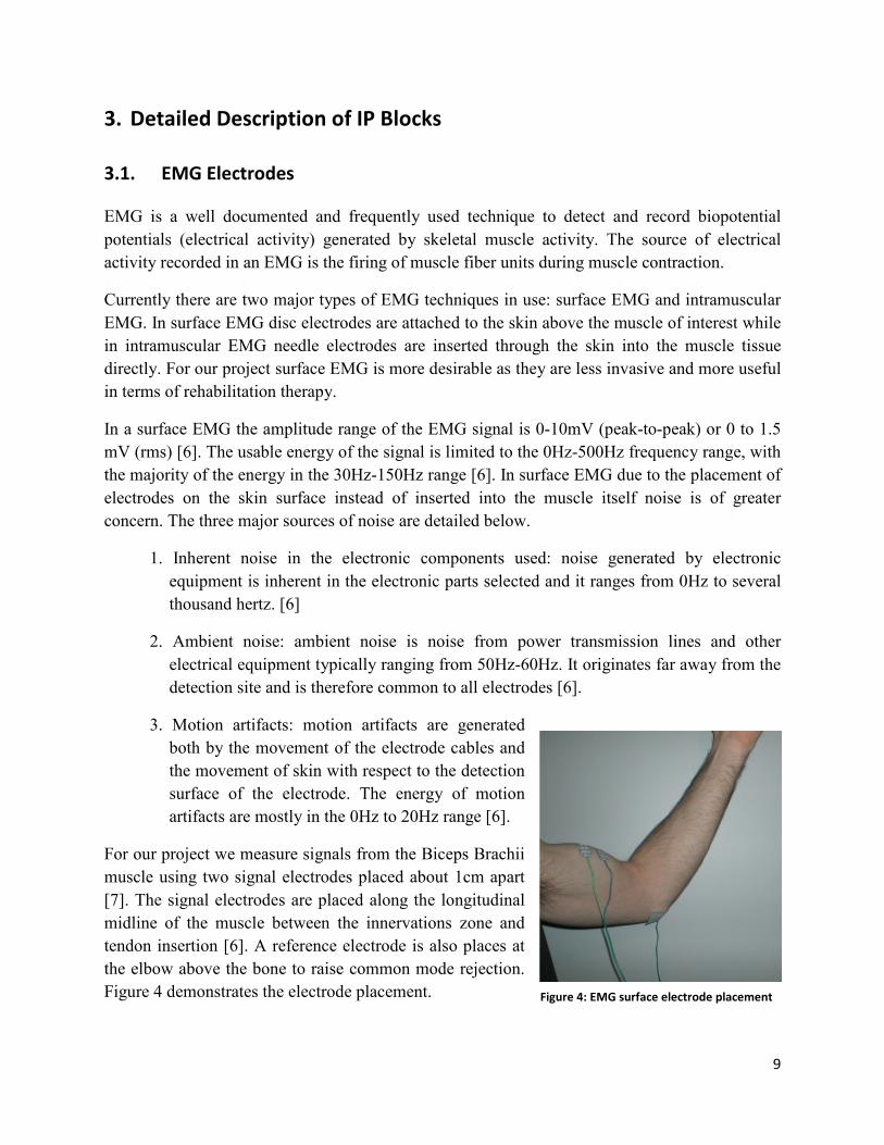
For our project we measure signals from the Biceps Brachii
muscle using two signal electrodes placed about 1cm apart
[7]. The signal electrodes are placed along the longitudinal
midline of the muscle between the innervations zone and
tendon insertion [6]. A reference electrode is also places at
the elbow above the bone to raise common mode rejection.
Figure 4 demonstrates the electrode placement. Figure 4: EMG surface electrode placement
10
3.2. Sensors
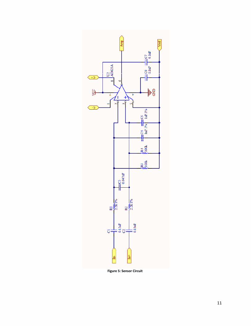
The input to each sensor is an analog differential signal with peak-to-peak voltage approximately
10 mV and unspecified common-mode voltage, band-limited to approximately 400 Hz [12],
measured through surface electromyography electrodes. The sensor stage therefore comprises an
instrumentation amplifier, which produces a single-ended output value relative to some given
reference voltage, and supporting components.
The instrumentation amplifier used is the Analog Devices AD623, selected for its relatively low
cost. A discrete instrumentation amplifier was chosen over constructing an amplifier from
multiple operational amplifiers due to the inaccuracies caused by the difficulty of matching
components [14]. A low-pass filter constructed from an RC circuit with −3 dB bandwidth fc = 40
kHz, located at the amplifier input, is necessary to prevent high-frequency interference from
introducing DC offset errors at the output [15], while a high-pass filter also constructed from an
RC circuit with −3 dB bandwidth fc = 10 Hz provides a return path for amplifier input bias
current [16] and helps to prevent movement artifacts (introduced by large-scale movements of
the limbs being measured) or a steady-state difference between the two electrodes from
saturating the amplifier [11]. An additional low-pass filter between the two ends of the
differential signal, is necessary to maintain effective common-mode rejection [15]; this filter has
−3 dB bandwidth fc = 900 Hz. This circuit is shown in Figure 5.
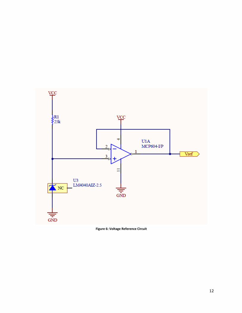
All analog circuitry used is rail-to-rail (i.e. can provide output signals close to their ground and
supply rails) with a supply voltage of 5 V. A National Semiconductor LM4040 voltage reference
is used to produce a 2.5 V reference voltage, which is buffered by one op-amp in a Microchip
MCP604 quad op-amp IC for each of the four input channels. Hence a 0 V difference between
the two differential inputs to a sensor results in a 2.5 V steady-state output from the
instrumentation amplifier. The voltage reference circuit is shown in Figure 6.
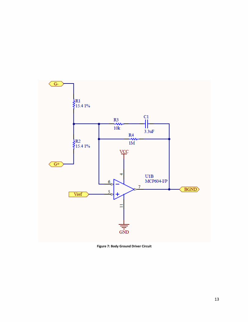
The AD623 accepts input voltages of at most 0.3 V outside the ground or supply voltages [15].
To ensure that this condition is reliably met, a first-order op-amp low-pass filter weakly drives a
body ground electrode, placed on a non-muscular patch of skin near the sensor electrodes, to
near the reference voltage [12]. This circuit is shown in Figure 7.
3.3. Analog Processor
Although digital signal processing is usually preferred to analog signal processing due to lower
cost and ease of reconfiguration, some analog low-pass filtering is necessary for correct analog-
to-digital conversion (see Section 3.4).
There are four major filter types [13]:
11
Figure 5: Sensor Circuit
12
Figure 6: Voltage Reference Circuit
13
Figure 7: Body Ground Driver Circuit
14
• Bessel filters have maximally linear phase response in the passband, i.e. they minimally
distort the shape of unattenuated waves. However, they have the slowest rolloff of the
four types for any given number of poles (filter complexity and cost is proportional to
number of poles.)
• Butterworth filters have maximally flat magnitude response in the passband, i.e. they
minimally distort the amplitude of unattenuated waves, and rolls off exponentially to zero
in the stopband. They have superior rolloff but inferior phase response to Bessel filters.
• Chebyshev filters (and inverse Chebyshev filters) have a steeper rolloff than Butterworth
or Bessel filters, but have ripple in the passband or stopband (i.e. small variations in the
gain for similar frequencies). They are also usually more complex to implement than
Bessel or Butterworth filters for a given number of poles.
• Elliptic filters have the steepest rolloff of all filters, but have ripple in both the passband
and stopband and are the most complex to implement.
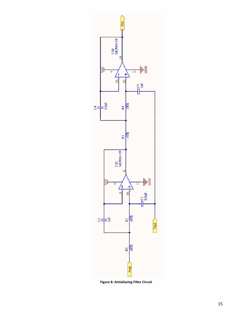
A bandwidth of fpass = 250 Hz is suffcient to collect the useful part of the surface EMG signal
[12]; given a sample rate of fs = 1.2 kHz, which defines a cutoff frequency of fstop = 600 Hz (see
Section 3.4), it was determined that a 4th-order (4-pole) Butterworth filter was an acceptable
trade off between phase response, filter sharpness, and filter complexity. The filter was
implemented using two cascaded 2nd-order op-amp filters in the common Sallen-Key
architecture, which is simple, effective, and tolerant of resistance and capacitance variations [14].
The circuit is shown in Figure 8.
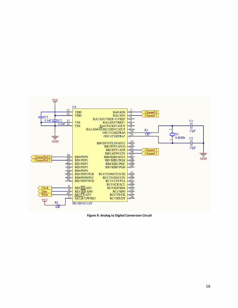
3.4. Analog to Digital Converter & adc_data_reader
The processed analog signal must be digitized before it can be used. A single Microchip
PIC18F4423 microcontroller samples all four input channels at 12-bit resolution and sends the
sampled data to the FPGA for further processing and usage. Its circuit is shown in Figure 9.
The sample rate for each channel was selected to be fs = 1200 Hz, based on a combination of
factors:
• The Nyquist criterion requires that a signal with bandwidth fc must be sampled at a rate
fs > 2fc to be represented correctly (without aliasing) [15]; given an EMG bandwidth of
400 Hz and additional bandwidth for filtering, this imposes the condition fs ≥ 1 kHz
usually seen on commercial EMG systems [12]. (The converse formulation, that a signal
sampled at fs must be bandlimited to 1 fs to prevent aliasing, motivates 2 the necessity of
analog filtering as described in Section 3.3.)
15
Figure 8: Antialiasing Filter Circuit
16
Figure 9: Analog to Digital Conversion Circuit

17
• Despite the use of differential input, significant mains interference (interference
corresponding to the ubiquitous AC power supply) tended to appear in the signal. While a
digital notch filter capable of removing a sinusoid of a single frequency is easily
implemented, various effects (especially a poorly-designed switched-mode power supply)
may emit non-sinusoidal interference at the mains frequency. Eliminating such
interference (i.e. signals of a given frequency and its harmonics) is most efficiently done
using a comb filter, which requires the sample rate to be an integer multiple of the
fundamental frequency to be notched. The most common mains frequencies worldwide
are 60 Hz and 50 Hz, so a sample rate that is an integer multiple of 300 Hz is desirable.
The microcontroller signals the FPGA using a custom I/O protocol using five wires, designated
clock, write, data, and the 2-bit signal channel. To send a sample, the microcontroller sets write
low and sets the channel signal according to which of the four channels has been sampled, then
pulses the clock, strobing out data from LSB to MSB to be latched on the rising edge. After all
12 bits have been written, write is set high. On the FPGA, a custom logic module contains four
12-bit serial-in, parallel-out shift registers (clocked by clock ) and some logic to send channel
and sample data to the signal processor through a Fast Simplex Link (FSL) (see Section 3.5)
when write is set high. Some two-flop synchronizers are used to prevent metastability issues
when crossing clock domains.
3.5. uB_input
Some digital signal processing is done to remove mains interference (see Section 3.4) and
eliminate movement artifacts [11]. The processing is primarily done by a MicroBlaze processor
configured with a barrel shifter and an integer multiplier. For performance reasons all arithmetic
is done in fixed point (all numbers are signed integers that are implicitly fractions of a power of
two). In processing done natively in the MicroBlaze, input samples, intermediate values, and
output values are in Q4.11 (16-bit fractions of 211 = 2048), while coefficients are in Q1.14 (16-
bit fractions of 214 = 16384). There are two major digital filter architectures [16]:
• Infinite impulse response (IIR) filters, which use feedback in their construction. IIR filters
are usually designed by reference to an analog filter, allowing the implementation of
common filters (such as low-pass, high-pass, or band-pass filters) with broad constraints
depending on the filter type (Butterworth, Chebyshev, etc.) (see Section 3.3). IIR filters
usually require less computation to achieve a given filter sharpness requirement.
However, they do not have linear phase response in general, and due to their use of
feedback, they may suffer from instability and compounded rounding errors in longer
filters.
• Finite impulse response (FIR) filters, which do not use feedback. FIR filters may
implement arbitrary functionality, can be designed to have linear phase response (i.e. all
frequencies are delayed by the same number of samples before appearing at the output) or
minimum phase, are always stable, and do not suffer from compounded rounding errors.
18
However, they usually require more computation to achieve a given sharpness
requirement than an analogous IIR filter.
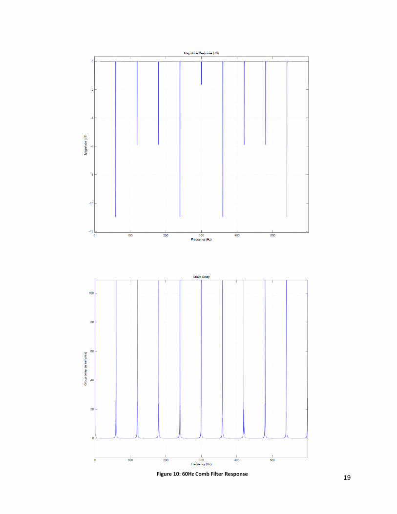
In this application, minimum phase (i.e. minimum group delay) is more important than linear
phase (i.e. constant group delay), since greater group delay will be perceived by a user as
increased input latency. For mains interference filtering, a comb filter (which is a pecial form of
IIR filter) is used due to its extremely high efficiency for notching harmonics; its magnitude
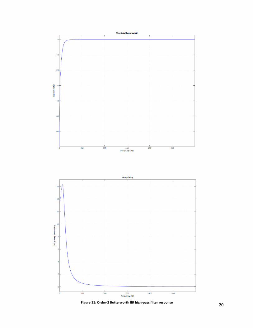
response and group delay are shown in Figure 10. For removing movement artifacts, both IIR
and FIR filters with similar magnitude responses and group delays may be constructed;
magnitude responses and group delays are shown in Figure 11 and Figure 12. Since the IIR filter
has no ripple, rolls off exponentially to zero at low frequencies, and is of low enough order for
rounding error to be of minimal concern, the IIR filter (an order-2 Butterworth filter with −3 dB
bandwidth fc = 20 Hz) was chosen for implementation. After a sample has been processed, its
magnitude is taken, and the sum of the past 128 processed sample magnitudes for that channel is
evaluated. If the sum exceeds an upper threshold, and the channel is currently marked as ‘not
asserted’, then the signal processor marks the channel as ‘asserted’ and sends the game processor
a signal via a FSL indicating that the channel has registered an input. Otherwise, if the sum drops
below a lower threshold, the channel is marked as ‘not asserted’. This scheme implements
hysteresis in the input mechanism to ensure that each user input results in exactly one input being
read by the game.
19
Figure 10: 60Hz Comb Filter Response
20
Figure 11: Order-2 Butterworth IIR high-pass filter response
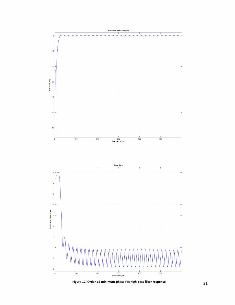
21
Figure 12: Order-63 minimum-phase FIR high-pass filter response
22
3.6. uB_game
The uB_game processor contains the game logic and a majority of the video memory
manipulation logic. As the game progresses it will continually read from and write to video
memory as well as other areas of memory. Most game state information, such as the location of
the snakes and the players’ scores are not stored locally, but instead stored on the boards
SDRAM. This is to ensure data can be shared between processors if necessary. Specifically the
uB_video processor, which needs to read player scores to manipulate the video display.
However, to avoid any severe race conditions or having asynchronous data, the uB_game
processor will e the only processor to write game state information to memory and all other
processors will only perform reads on these sections of memory.
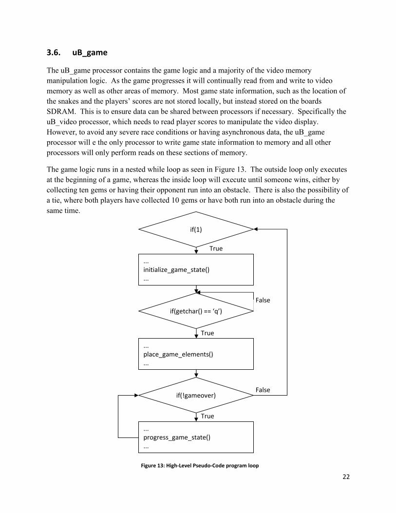
The game logic runs in a nested while loop as seen in Figure 13. The outside loop only executes
at the beginning of a game, whereas the inside loop will execute until someone wins, either by
collecting ten gems or having their opponent run into an obstacle. There is also the possibility of
a tie, where both players have collected 10 gems or have both run into an obstacle during the
same time.
False
True
True
False
...
initialize_game_state()
...
if(1)
...
place_game_elements()
...
if(getchar() == ‘q’)
if(!gameover)
...
progress_game_state()
...
True
Figure 13: High-Level Pseudo-Code program loop
23
To initialize the game state, each player’s score is set to zero and their snakes are returned to
their respective starting positions be overwriting the value of the snake locations in memory with
their default values. Before the game can start a ‘q’ character must come through the UART to
the FPGA. This is the only form of input the game processor receives that is not a form of EMG
signal. We decided to have the game start way, instead of through one player’s EMG signal to
prevent any “head starts” from occurring.
Once the game starts, the program advances the snakes by calculating a new position for each
snake’s head (determined by the direction they are traveling). Then the location values for each
segment of the snake are shifted toward the end of the snake such that the second segment of the
snake now has the head’s old position value, and the third segment has the second’s and so on.
After that the head gets the newly calculated position value. To visually advance the snake on
the video display, the game will “erase” the last segment of the snake and “draw” the head at its
new position.
However, in each iteration of the game loop before advancing the snake it is necessary to check
if the new position that was calculated resides outside the game area or is occupied by a gem, the
players own snake, the player’s opponent’s snake, or an obstacle. To perform this check, the
game logic will read the colour values of each pixel in the new position to determine if it is being
occupied. Any result that is not a gem or an unoccupied space will cause the player to lose the
game. It is important to note that before declaring a winner, the new position of both players is
check to ensure a tie hasn’t occurred.
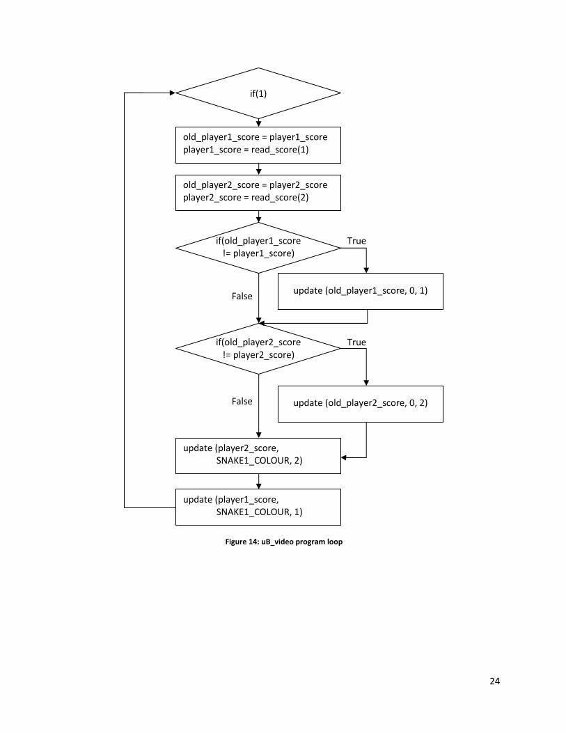
3.7. uB_video
Comparatively the uB_video processor executes far less complex program than the uB_game
processor. While originally meant to handle all of the video output, it now updates only the
areas of the video display that are to the left and right of the “game area”. Following a simple
loop as illustrated in Figure 14, the uB_video processor continuously checks for a change in the
players’ scores. If one occurs, it will overwrite the old score on the video display and replace it
with the new one, and add a gem to that user’s side of the screen.
24
if(old_player1_score
!= player1_score)
if(old_player2_score
!= player2_score)
False
old_player1_score = player1_score
player1_score = read_score(1)
old_player2_score = player2_score
player2_score = read_score(2)
update (old_player1_score, 0, 1)
update (old_player2_score, 0, 2)
update (player2_score,
SNAKE1_COLOUR, 2)
update (player1_score,
SNAKE1_COLOUR, 1)
if(1)
True
True
False
Figure 14: uB_video program loop
25
3.8. GPIOs & audio_core_0
To add sound to our game without building an audio controller from scratch, we looked to past
projects for an audio implementation that we could integrate into our system. We found one
suitable enough in the Virtual Pong project from 2010.
(http://www.eecg.toronto.edu/~pc/courses/532/2011/pastprojectsnode6.html)
They utilized an audio pcore from Embedded Computing to interface with the LM4550 National
Semiconductor audio codec chip located on the XUP board along with several XPS GPIO units
to produce various sounds for their game related project. Their custom logic for the audio core,
which utilizes a moore-type state machine and 11-bit counter, can produce single, double, 5 and
6 tones beeps depending on the game state. The core receives game state information from the
various GPIO units.
Our system feeds the audio core game state information in the same manner, through three
GPIOs which are written to by the uB_game processor.
1. gpio_game_running
This GPIO contains a single 1 bit wide data channel, which the uB_game processor
writes to indicate if the game is running. No sounds will be produced if this channel has
not been set.
2. gpio_game_start_end
This GPIO contains two 1 bit wide data channels. One indicates when a game has started
and another when a game has ended when they are ser respectively. Two channels are
necessary so that we can have a start where a game hasn’t ended, but also hasn’t just
started.
3. gpio_point
This GPIO also contains two 1 bit wide data channels. One channel is set whenever
either player collects a gem and earns a point. The other channel is set when a collision
occurs, either between players or a player and an obstacle.
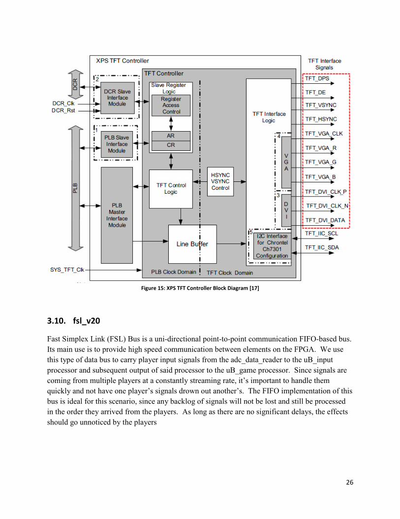
3.9. video_out
The video_out block of the system consists of a XPS TFT controller whose sole purpose is to
read frames of video from memory and send them through the SVGA port to the video display.
As such it is connected to the MPMC via its own PLB line to prevent unnecessary congestion on
the main bus line.
26
Figure 15: XPS TFT Controller Block Diagram [17]
3.10. fsl_v20
Fast Simplex Link (FSL) Bus is a uni-directional point-to-point communication FIFO-based bus.
Its main use is to provide high speed communication between elements on the FPGA. We use
this type of data bus to carry player input signals from the adc_data_reader to the uB_input
processor and subsequent output of said processor to the uB_game processor. Since signals are
coming from multiple players at a constantly streaming rate, it’s important to handle them
quickly and not have one player’s signals drown out another’s. The FIFO implementation of this
bus is ideal for this scenario, since any backlog of signals will not be lost and still be processed
in the order they arrived from the players. As long as there are no significant delays, the effects
should go unnoticed by the players

27
3.11. clock_generator
The clock generator can provide various clock signals based on specified requirements. In our
system we generate a 100MHz “system clock” that is used by all PLBs, FSLs, the audio core and
DDR_SDRAM. A slower clock, at 25MHz, is created for the TFT controller since it is
constantly reading video memory. The MPMC also takes two other clock signals: one shifter by
47 degrees the other by 90 degrees.
Figure 17: Clock Generator Block Diagram [19]
Figure 16: Fast Simplex Link (FSL) Bus Block Diagram [18]

28
4. Design Tree Description
• emgvideogame - root directory
o system.xmp - XPS Project File
o system.mss - System Hardware Specification file
o system.mhs - System Software Specification file
o _xps - Option files for bitinit, libgen, simgen and platgen
o blkdiagram - Block diagram gerenated by Xilinx tools
o data - System Constraints File
� system.ucf
o drivers - Drivers for custom pcores
� adc_data_reader_v1_00_a
o etc - Option files for bitgen and downloading
o Input - uB_input executable file
� executable.elf
o lib - IP Library for XUP board
� XilinxProcessorIP
o pcores - Custom hardware peripherals
� adc_data_reader_v1_00_a
� audio_core_v1_00_a
o sw - Custom software and ub_game executable and linker file
� bioefilt.c
� bioefilt.h
� constants.h
� exec.elf
� input.c
� linker.ld
� main.c
� shared.c
29
� shared.h
� VGA.h
� video.c
o ub_game - Software library files for uB_game processor
o ub_input - Software library files for uB_input processor
o ub_video - Software library files for uB_video processor
o Video - uB_video executable file
� executable.elf
30
5. References
[1] Pullman SL, Goodin DS, Marquinez AI, Tabbal S, Rubin M. Clinical utility of surface
SEMG: report of the Therapeutics and Technology Assessment Subcommittee of the
American Academy of Neurology. Neurology 2000, v55: 171-177
[2] Kleissen RFM, Buurke JH, Harlaar J, Zilvold G, Electromyography in the biomechanical analysis of
human movement and its clinical application. Gait Posture, 1998, v8(2):143–158
[3] Pons JL, Rocon E, Ceres R, et. al. The MANUS-HAND Dextrous Robotics Upper Limb
Prosthesis: Mechanical and Manipulation Aspects. Autonomous Robotics, 2004, v16: 143-163
[4] Kuiken T, et. al, Targeted Muscle Reinnervation for Real-time Myoelectric Control of
Multifunction Artificial Arms, Journal of the American Medical Association 301, 2009,
v301(6): 319-628
[5] Robinson AJ, Snyder-Mackler L, Clinical electrophysiology: Electrotherapy and
electrophysiological testing, 1995, Williams & Wilkins, Baltimore
[6] De Luca CJ, Surface Electromygraphy: Detection and Recording, 2002, DelSys Incorporated
[7] Hidalgo M, Tene G, Sanchez A. Fuzzy Control of a Robotic Arm using EMG Signals,
International Conference on Industrial Electronics and Control Application, 2005
[8] A. Sedra and K. Smith, Microelectronic Circuits, 6th ed. 2009.
[9] AD623, datasheet, Analog Devices, 2008.
[10] C. Kitchin and L. Counts, A Designer’s Guide to Instrumentation Amplifiers, 3rd
ed.,Analog Devices, 2006.
[11] C. J. D. Luca, L. D. Gilmore, M. Kuznetsov, and S. H. Roy, “Filtering the surface EMG
signal: Movement artifact and baseline noise contamination,” Journal of Biomechanics, vol.
43, no. 8, pp. 1573–1579, May 2010.
[12] F. Hardala and R. Canal, “EMG circuit design and AR analysis of EMG signs,” Journal of
Medical Systems, vol. 28, no. 6, pp. 633–642, Dec. 2004.
[13] R. Schaumann and M. E. V. Valkenburg, Design of Analog Filters, 2nd ed. University
Press, 2000.
[14] T. T. Tran, High-Speed DSP and Analog System Design. Springer, 2010.
[15] A. V. Oppenheim, A. S. Willsky, and S. H. Nawab, Signals and Systems, 2nd ed. Prentice
Hall, 1996.
31
[16] A. V. Oppenheim and R. W. Schafer, Discrete-Time Signal Processing, 3rd ed. Prentice
Hall, 2009. Oxford University Press, Oxford
[17] XPS Thin Film Transistor (TFT) Controller (v1.00a) datasheet
%EDK\hw\XilinxProcessorIPLib\pcores\xps_tft_v1_00_a\doc\xps_tft.pdf
[18] Fast Simplex Link(FSL) Bus (v2.11a) datasheet
%EDK\hw\XilinxProcessorIPLib\pcores\fsl_v20_v2_11_a\doc\fsl_v20.pdf
[19] Clock Generator (v2.01a) datasheet
%EDK\hw\XilinxProcessorIPLib\pcores\clock_generator_v2_01_a\doc\clock_generator.pdf