Embed Size (px)
Citation preview
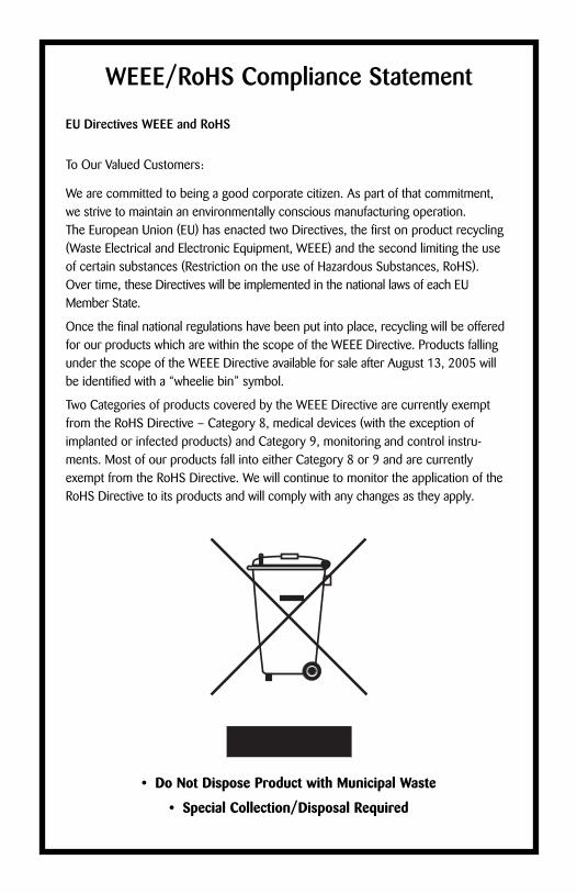
User’s ManualECM® 630 Electroporation System
Publication 5501-003-REV-C
MA1 45-0051 ECM® 630 Electroporator only (110V)MA1 45-0051int ECM® 630 Electroporator only (220V)
EU Directives WEEE and RoHS
To Our Valued Customers:
We are committed to being a good corporate citizen. As part of that commitment, we strive to maintain an environmentally conscious manufacturing operation. The European Union (EU) has enacted two Directives, the first on product recycling(Waste Electrical and Electronic Equipment, WEEE) and the second limiting the useof certain substances (Restriction on the use of Hazardous Substances, RoHS). Over time, these Directives will be implemented in the national laws of each EUMember State.
Once the final national regulations have been put into place, recycling will be offeredfor our products which are within the scope of the WEEE Directive. Products fallingunder the scope of the WEEE Directive available for sale after August 13, 2005 willbe identified with a “wheelie bin” symbol.
Two Categories of products covered by the WEEE Directive are currently exemptfrom the RoHS Directive – Category 8, medical devices (with the exception ofimplanted or infected products) and Category 9, monitoring and control instru-ments. Most of our products fall into either Category 8 or 9 and are currentlyexempt from the RoHS Directive. We will continue to monitor the application of theRoHS Directive to its products and will comply with any changes as they apply.
• Do Not Dispose Product with Municipal Waste
• Special Collection/Disposal Required
WEEE/RoHS Compliance Statement
ECM® 630 Electroporation System
Page 1 www.btxonline.com
Table of ContentsGeneral Information:
Serial Number ................................................................2Calibration ......................................................................2Warranty ....................................................................2-3Service........................................................................3-4Repair Facilities and Parts ..............................................4
General Safety Summary..............................................5-6Electrical & Technical Specifications ..............................7General Specifications......................................................8Introduction:
ECM® 630 Features ......................................................9Operation: Getting Started ............................................10Quick Start:
Installation ....................................................................11Connecting ..................................................................11Initializing......................................................................11Instrument Controls................................................12-17
Operating Basics ......................................................18-19Advanced Operation: Programming ............................20Electroporation ..............................................................21Applications:
Electroporation ......................................................22-23Appendix A: ECM® 630 Electrode
Operation Ranges................................24-26Appendix B: ECM® 630 RC Time Constants............27-38Appendix C: Optimization Strategies............................39Appendix D: Electrical Troubleshooting........................40Appendix E: Experimental Troubleshooting ................41Appendix F: Glossary of Electrical Terms ....................42Appendix G: Glossary of Biological &
Technical Terms ..................................43-44Appendix H: Electroporation Generator
Compatibility ............................................45Appendix I: Recommended Reading ............................46Appendix J: Accessories and Replacement Parts ........47Appendix K: General Care and Cleaning......................48
ECM® 630 Electroporation System
Page 2 www.btxonline.com
General Information
Serial NumberThe serial number for the ECM® 630 is located on the rear of theinstrument case. All inquiries concerning these products should referto the serial numbers on the units.
CalibrationThere is no calibration required for the ECM® 630.
WarrantyBTX - Harvard Apparatus warranties the ECM® 630 for a period of twoyears from the date of purchase. At its option, BTX – HarvardApparatus will repair or replace the unit if it is found to be defective asto workmanship or materials. This warranty does not extend to anyinstrumentation which has been (a) subjected to misuse, neglect, acci-dent or abuse, (b) repaired or altered by anyone other than BTX - HARVARD APPARATUS without BTX - HARVARD APPARATUS’express and prior approval, (c) used in violation of instructions fur-nished by BTX - HARVARD APPARATUS. This warranty extends onlyto the original customer purchaser.
IN NO EVENT SHALL BTX - HARVARD APPARATUS BE LIABLE FORINCIDENTAL OR CONSEQUENTIAL DAMAGES. Some states do notallow exclusion or limitation of incidental or consequential damages sothe above limitation or exclusion may not apply to you. THERE ARENO IMPLIED WARRANTIES OF MERCHANTABILITY, OR FITNESSFOR A PARTICULAR USE, OR OF ANY OTHER NATURE. Some statesdo not allow this limitation on an implied warranty, so the above limi-tation may not apply to you.
Without limiting the generality of the foregoing, BTX - HARVARDAPPARATUS shall not be liable for any claims of any kind whatsoever,as to the equipment delivered or for non-delivery of equipment, andwhether or not based on negligence.
Warranty is void if the ECM® 630 is changed in any way from its origi-nal factory design or if repairs are attempted without written authoriza-tion by BTX - HARVARD APPARATUS.
Warranty is void if parts, connections or cell fusion chambers notmanufactured by BTX - HARVARD APPARATUS are used with theECM® 630.
ECM® 630 Electroporation System
Page 3 www.btxonline.com
General Information (Continued)
If a defect arises within the warranty period, promptly contact BTX –Harvard Apparatus, 84 October Hill Road, Building 7, Holliston,Massachusetts, USA 01746-1388 using our toll free number 1-800-272-2775 (US Only) or 508-893-8999(E-mail: [email protected]). Goods will not beaccepted for return unless an RMA (Returned Materials Authorization)number has been issued by our customer service department. Thecustomer is responsible for shipping charges. Please allow a reason-able period of time for completion of repairs, replacement and return.If the unit is replaced, the replacement unit is covered only for theremainder of the original warranty period dating from the purchase ofthe original device.
This warranty gives you specific rights, and you may also have otherrights, which vary from state to state.
ServiceAll service under the warranty will be made at the BTX - HARVARDAPPARATUS, Holliston, Massachusetts facilities or an authorizedservice site. Owner will ship instrument prepaid to Holliston,Massachusetts, USA or the service site. BTX - HARVARD APPARATUSwill return the instrument after servicing, freight prepaid to owner’saddress.
Obtaining Service:Service During Warranty
1. Write or call the BTX - HARVARD APPARATUS Customer Support Group and describe the nature of the problem.
2. Carry out minor adjustments or tests as suggested by BTX - HARVARD APPARATUS.
3. If proper performance is not obtained, BTX - HARVARD APPARATUS will notify you to ship the instrument, prepaid, to its Service Department.The instrument will be repaired and returned at no charge for all customers in the continental United States.
Customers outside of the continental United States who have purchased our equipment from distributors should contact the distributor. If you have purchased your equipment from us, youshould contact us directly. We will repair at no charge, but will notpay for shipment, documentation, etc. These charges will be billedat cost.
Note: Under no condition should the instrument or accessories bereturned without prior approval from BTX - HARVARD APPARATUS. AnRMA (Returned Materials Authorization) number must be obtained.
ECM® 630 Electroporation System
Page 4 www.btxonline.com
General Information (continued)
Out-Of-Warranty ServiceProceed exactly as for Warranty Service, above. If our ServiceDepartment can assist you by phone or correspondence, we will beglad to, at no charge.
Repair service will be billed on the basis of labor and materials. Acomplete statement of time spent and materials used will be supplied.Shipment to BTX - HARVARD APPARATUS should be prepaid. Yourbill will include return shipment freight charges.
Disassembly by the user is prohibited. Service should only be carried outby experienced BTX - HARVARD APPARATUS technicians.
Repair Facilities and PartsBTX - Harvard Apparatus stocks replacement and repair parts. Whenordering, please describe parts as completely as possible, preferablyusing our part numbers. If practical, enclose a sample or drawing. Weoffer complete reconditioning service.
ECM® 630 Electroporation System
Page 5 www.btxonline.com
General Safety SummaryReview the following safety precautions to avoid injury and preventdamage to this product or any products connected to it. To avoidpotential hazards, use this product only as specified.
Only qualified personnel should perform service procedures.
To Avoid Fire or Personal Injury
USE PROPER POWER CORDUse only the power cord specified for this product and certified forthe country of use.
CONNECT AND DISCONNECT PROPERLYDo not connect or disconnect probes or test leads while they areconnected to a power source.
GROUND THE PRODUCTThis product is grounded through the grounding conductor of thepower cord. To avoid electric shock, the grounding
conductor must be connected to earth ground. Before making connections to the output terminals of the product, ensure that theproduct is properly grounded.
OBSERVE ALL TERMINAL RATINGSTo avoid fire or shock hazard, observe all ratings and markings on theproduct. Consult the product manual for further ratings informationbefore making connections to the product.
DO NOT OPERATE WITHOUT COVERSDo not operate this product with covers or panels removed.
Use Proper Fuse. Use only the fuse type and rating specified for thisproduct.
AVOID EXPOSURE TO CIRCUITRYDo not touch exposed connections and components when power ispresent.
DO NOT OPERATE WITH SUSPECTED FAILURESIf you suspect there is damage to this product, have it inspected byqualified service personnel.
PROVIDE PROPER VENTILATIONRefer to installation instructions for details on installing the product toensure proper ventilation.
DO NOT OPERATE IN WET/DAMP CONDITIONS
DO NOT OPERATE IN AN EXPLOSIVE ATMOSPHERE
KEEP PRODUCT SURFACES CLEAN AND DRYShould you have any safety concerns, immediately contact BTXTechnical Services (1-800-272-2775)
ECM® 630 Electroporation System
Page 6 www.btxonline.com
General Safety Summary (Continued)
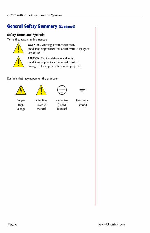
Safety Terms and Symbols:Terms that appear in this manual:
WARNING. Warning statements identify conditions or practices that could result in injury orloss of life.
CAUTION. Caution statements identify conditions or practices that could result in damage to these products or other property.
Symbols that may appear on the products:
Danger Attention Protective Functional
High Refer to (Earth) GroundVoltage Manual Terminal
ECM® 630 Electroporation System
Page 7 www.btxonline.com
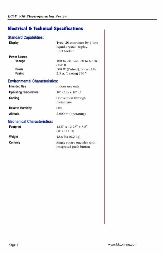
Electrical & Technical Specifications
Standard Capabilities:Display Type: 20-character by 4-line
liquid crystal Display. LED backlit
Power SourceVoltage 100 to 240 Vac, 50 to 60 Hz,
CAT IIPower 500 W (Pulsed), 50 W (Idle)Fusing 2.5 A, T rating 250 V
Environmental Characteristics:Intended Use Indoor use only
Operating Temperature 10° C to + 40° C
Cooling Convection through metal case
Relative Humidity 60%
Altitude 2,000 m (operating)
Mechanical Characteristics:Footprint 12.5” x 12.25” x 5.5”
(W x D x H)
Weight 13.6 lbs (6.2 kg)
Controls Single rotary encoder with integrated push button
ECM® 630 Electroporation System
Page 8 www.btxonline.com
General Specifications
Certifications and CompliancesOvervoltage Category:
CAT III: Products in this Category: Distribution-level mains, fixed installation.
CAT II: Local-level mains, applications, portable equipment.
CAT I: Signal levels in special equipment or parts of equipment, telecommunications, electronics.
Meets requirements of Directive 89/336/EEC for ElectromagneticCompatibility (EC) and Low-Voltage Directive 73/23/EEC forProduct Safety. Compliance was demonstrated to the following specifications aslisted in the Official Journal of the European Communities:
EN 50081-1 Emissions
EN 55011 Class B Radiated and Conducted Emissions
EN 55082-1 Immunity
IEC 10004-2 Electrostatic Discharge Immunity
IEC 10004-3 RF Electromagnetic Field Immunity
IEC 10004-4 Electrical Fast Transient/Burst Immunity
Low Voltage Directive 73/23/EEC
ECM® 630 Electroporation System
Page 9 www.btxonline.com
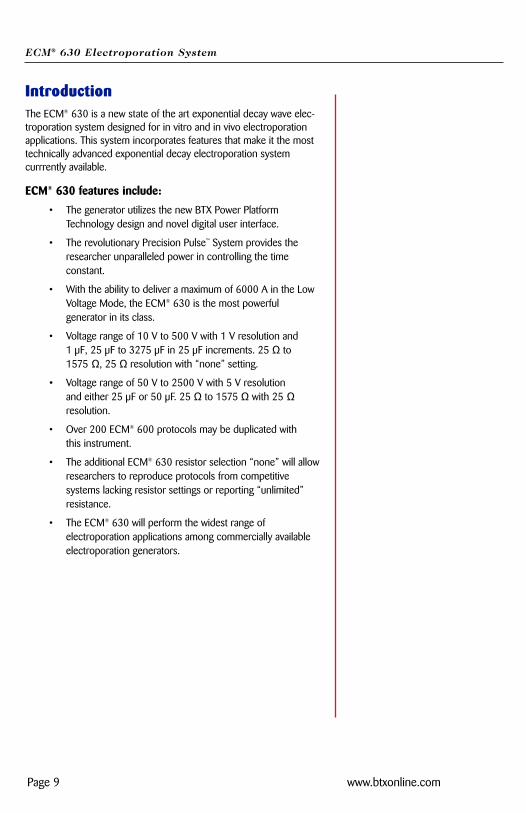
IntroductionThe ECM® 630 is a new state of the art exponential decay wave elec-troporation system designed for in vitro and in vivo electroporationapplications. This system incorporates features that make it the mosttechnically advanced exponential decay electroporation system currrently available.
ECM® 630 features include:
• The generator utilizes the new BTX Power Platform Technology design and novel digital user interface.
• The revolutionary Precision Pulse™ System provides the researcher unparalleled power in controlling the time constant.
• With the ability to deliver a maximum of 6000 A in the Low Voltage Mode, the ECM® 630 is the most powerful generator in its class.
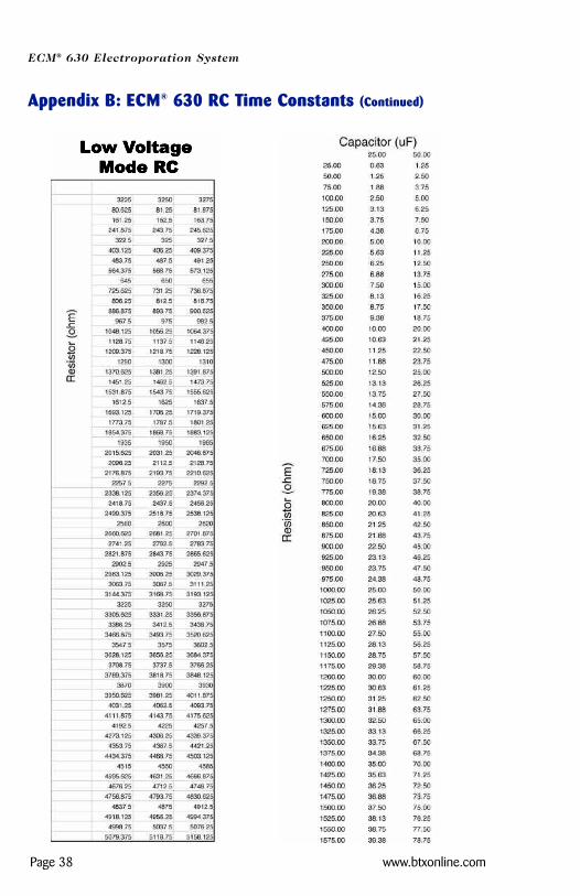
• Voltage range of 10 V to 500 V with 1 V resolution and 1 µF, 25 µF to 3275 µF in 25 µF increments. 25 Ω to 1575 Ω, 25 Ω resolution with “none” setting.
• Voltage range of 50 V to 2500 V with 5 V resolution and either 25 µF or 50 µF. 25 Ω to 1575 Ω with 25 Ωresolution.
• Over 200 ECM® 600 protocols may be duplicated with this instrument.
• The additional ECM® 630 resistor selection “none” will allowresearchers to reproduce protocols from competitive systems lacking resistor settings or reporting “unlimited” resistance.
• The ECM® 630 will perform the widest range of electroporation applications among commercially available electroporation generators.
ECM® 630 Electroporation System
Page 10 www.btxonline.com
Operation: Getting StartedCarefully open the box containing the ECM® 630 ElectroporationSystem. Verify receipt of the following items:
ECM® 630 Pulse Generator (1)
Power Cord (1)
Model 630E Electronic Manual (1)
BTX Electroporation Systems may be customized with the additionof various electrodes and accessories. The following items com-plete a typical system order:
Model 630B Electroporation Safety Stand (1)
Model 660 Cuvette Rack (1)
Model 610 BTX Cuvettes Plus (10)
Model 620 BTX Cuvettes Plus (10)
Model 640 BTX Cuvettes Plus (10)
If you have ordered alternative or different items, please verifytheir receipt.
ECM® 630 Electroporation System
Page 11 www.btxonline.com
Quick Start
Installation
1. Install on a bench or work table.
2. Allow a 1 to 2 inch clearance for proper cooling. It is normalfor the instrument to be slightly warmer than its’ operating environment.
3. Choose an outlet that is readily accessible.
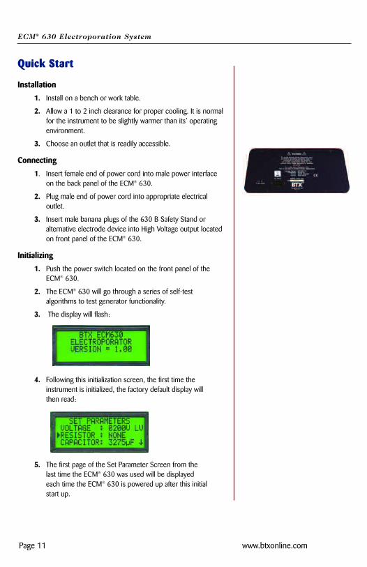
Connecting
1. Insert female end of power cord into male power interface on the back panel of the ECM® 630.
2. Plug male end of power cord into appropriate electrical outlet.
3. Insert male banana plugs of the 630 B Safety Stand or alternative electrode device into High Voltage output located on front panel of the ECM® 630.
Initializing
1. Push the power switch located on the front panel of the ECM® 630.
2. The ECM® 630 will go through a series of self-test algorithms to test generator functionality.
3. The display will flash:
4. Following this initialization screen, the first time the instrument is initialized, the factory default display will then read:
5. The first page of the Set Parameter Screen from the last time the ECM® 630 was used will be displayed each time the ECM® 630 is powered up after this initial start up.
ECM® 630 Electroporation System
Page 12 www.btxonline.com
Quick Start (Continued)
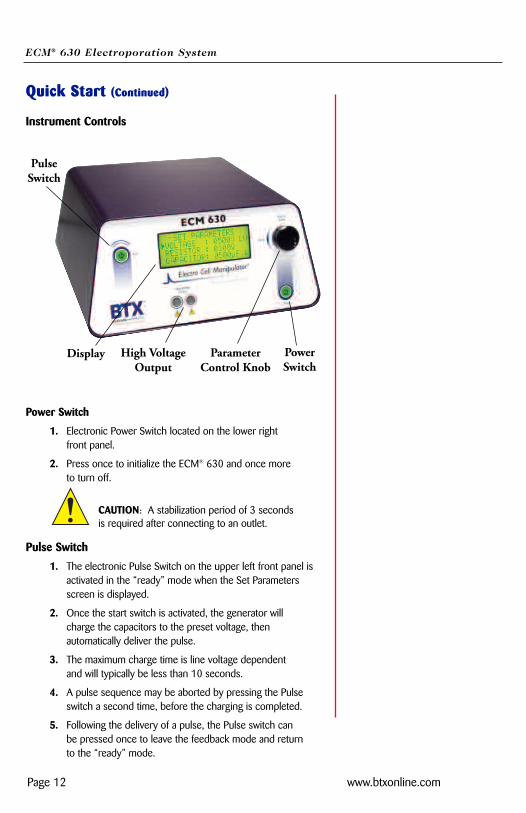
Instrument Controls
Power Switch
1. Electronic Power Switch located on the lower rightfront panel.
2. Press once to initialize the ECM® 630 and once more to turn off.
CAUTION: A stabilization period of 3 seconds is required after connecting to an outlet.
Pulse Switch
1. The electronic Pulse Switch on the upper left front panel is activated in the “ready” mode when the Set Parameters screen is displayed.
2. Once the start switch is activated, the generator will charge the capacitors to the preset voltage, then automatically deliver the pulse.
3. The maximum charge time is line voltage dependent and will typically be less than 10 seconds.
4. A pulse sequence may be aborted by pressing the Pulse switch a second time, before the charging is completed.
5. Following the delivery of a pulse, the Pulse switch can be pressed once to leave the feedback mode and return to the “ready” mode.
Display High VoltageOutput
PowerSwitch
ParameterControl Knob
PulseSwitch
ECM® 630 Electroporation System
Page 13 www.btxonline.com
Quick Start (Continued)
Parameter Control KnobThe Parameter Control Knob is a rotary encoder controlling both theparameter under control and the value of the parameter under control.
1. The display will indicate which parameter is under control bythe presence of an arrow to the left of the parameter.
2. To select a parameter to adjust, rotate the knob until the arrow is to the left of the desired parameter, then push to select. The arrow will move to the right of the value displayedfor that parameter.
3. To adjust the value of a parameter under control, rotate the knob clockwise to increase the value and counter clockwise to decrease it. Once values are adjusted, push the knob to lock settings and arrow will return to left of parameters under control.
4. In order to move between screens, move the cursor to the bottom of the screen and rotate the knob clockwise to moveto the next screen.
5. In order to move to the previous screen, move the cursor tothe top of the screen and rotate the knob counterclockwise.
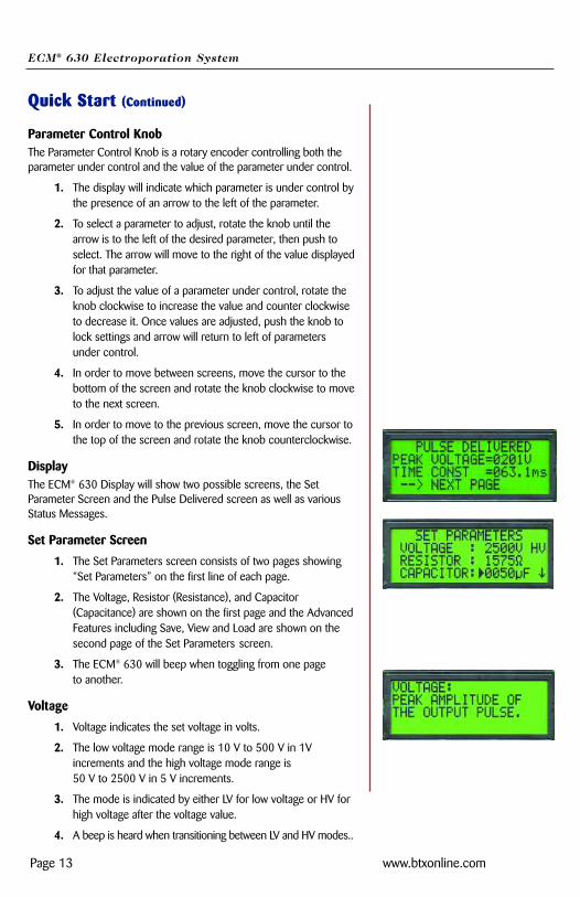
DisplayThe ECM® 630 Display will show two possible screens, the SetParameter Screen and the Pulse Delivered screen as well as variousStatus Messages.
Set Parameter Screen
1. The Set Parameters screen consists of two pages showing “Set Parameters” on the first line of each page.
2. The Voltage, Resistor (Resistance), and Capacitor (Capacitance) are shown on the first page and the AdvancedFeatures including Save, View and Load are shown on the second page of the Set Parameters screen.
3. The ECM® 630 will beep when toggling from one page to another.
Voltage
1. Voltage indicates the set voltage in volts.
2. The low voltage mode range is 10 V to 500 V in 1V increments and the high voltage mode range is 50 V to 2500 V in 5 V increments.
3. The mode is indicated by either LV for low voltage or HV for high voltage after the voltage value.
4. A beep is heard when transitioning between LV and HV modes..
ECM® 630 Electroporation System
Page 14 www.btxonline.com
Quick Start (Continued)
Resistor
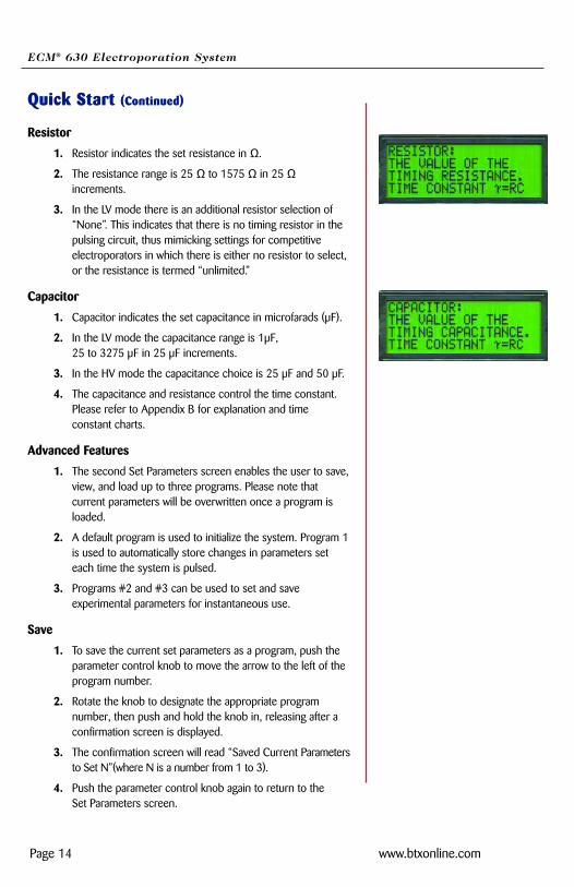
1. Resistor indicates the set resistance in Ω.
2. The resistance range is 25 Ω to 1575 Ω in 25 Ωincrements.
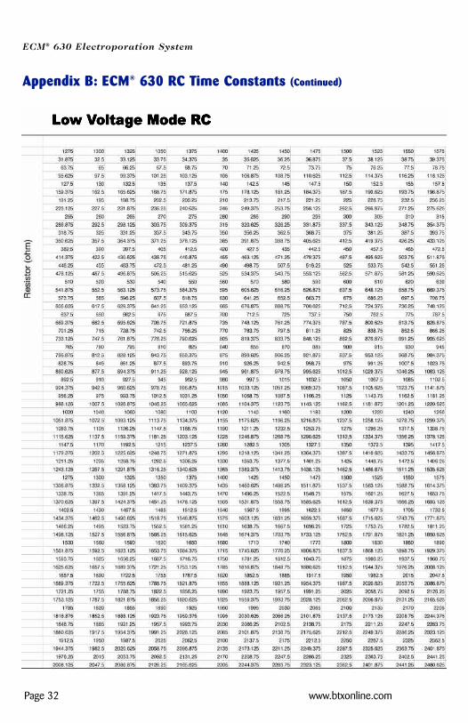
3. In the LV mode there is an additional resistor selection of “None”. This indicates that there is no timing resistor in the pulsing circuit, thus mimicking settings for competitive electroporators in which there is either no resistor to select, or the resistance is termed “unlimited.”
Capacitor
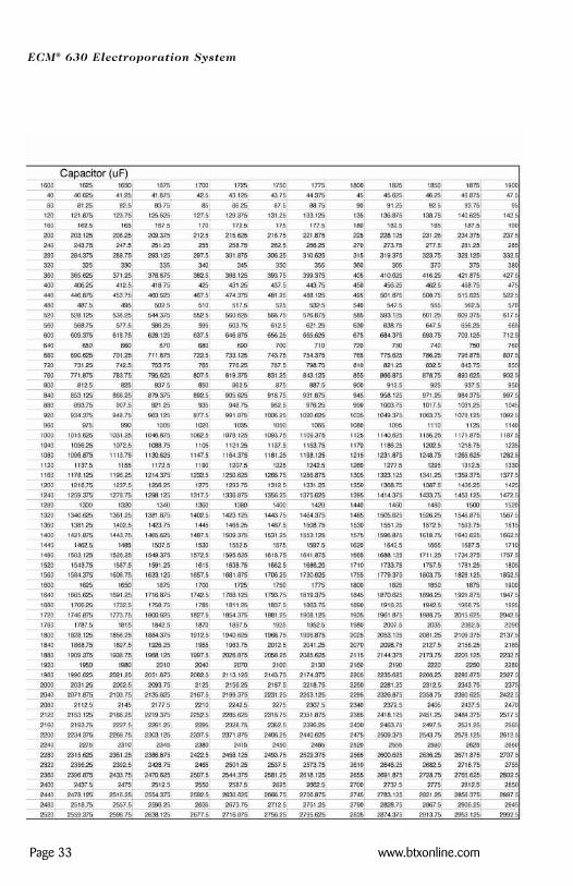
1. Capacitor indicates the set capacitance in microfarads (µF).
2. In the LV mode the capacitance range is 1µF, 25 to 3275 µF in 25 µF increments.
3. In the HV mode the capacitance choice is 25 µF and 50 µF.
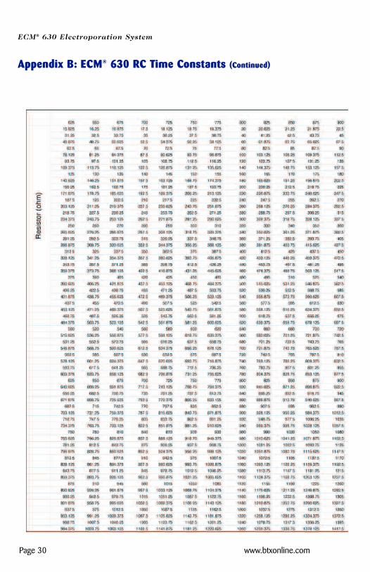
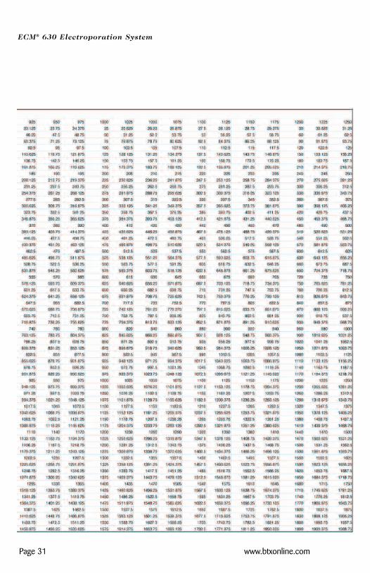
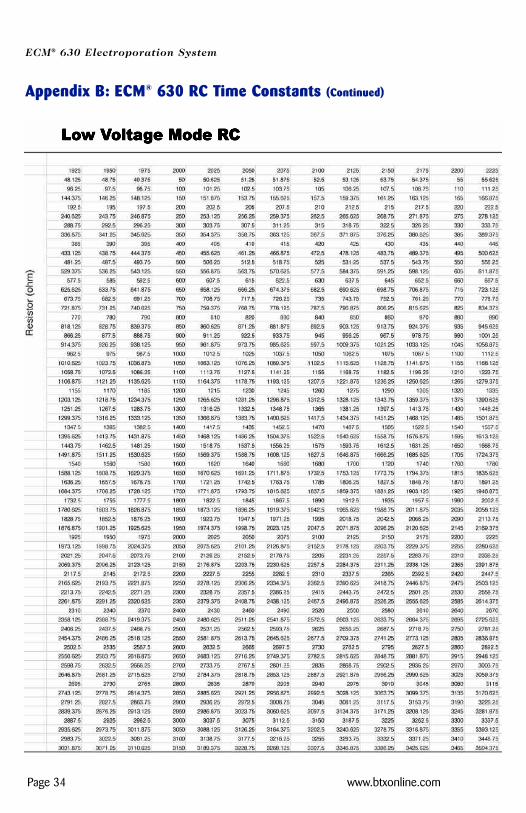
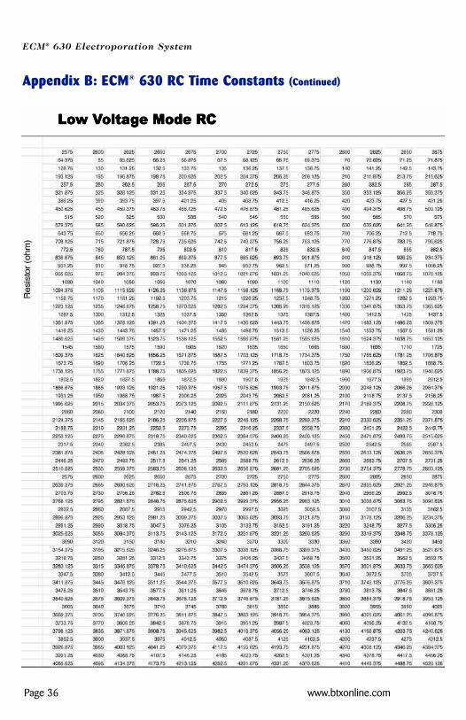
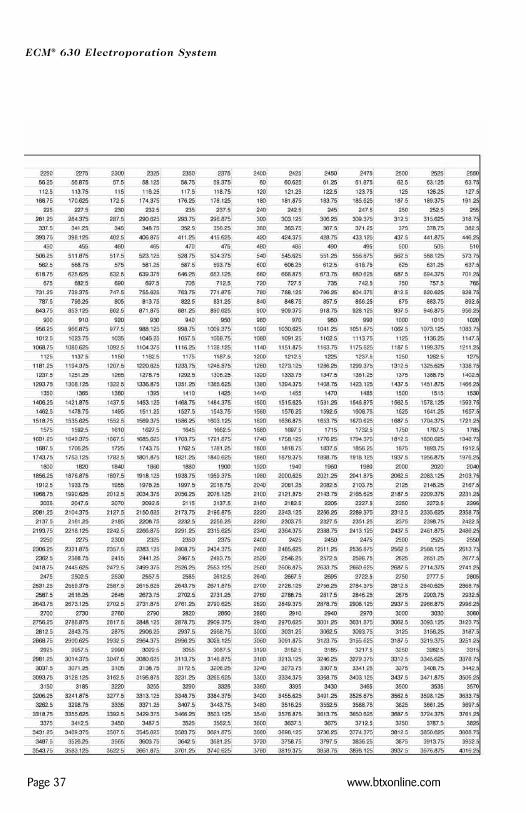
4. The capacitance and resistance control the time constant. Please refer to Appendix B for explanation and time constant charts.
Advanced Features
1. The second Set Parameters screen enables the user to save,view, and load up to three programs. Please note that current parameters will be overwritten once a program is loaded.
2. A default program is used to initialize the system. Program 1is used to automatically store changes in parameters set each time the system is pulsed.
3. Programs #2 and #3 can be used to set and save experimental parameters for instantaneous use.
Save
1. To save the current set parameters as a program, push the parameter control knob to move the arrow to the left of the program number.
2. Rotate the knob to designate the appropriate program number, then push and hold the knob in, releasing after a confirmation screen is displayed.
3. The confirmation screen will read “Saved Current Parametersto Set N”(where N is a number from 1 to 3).
4. Push the parameter control knob again to return to the Set Parameters screen.
ECM® 630 Electroporation System
Page 15 www.btxonline.com
Quick Start (Continued)
View
1. To view the appropriate program parameters, push the parameter control knob to move the arrow to the left of the program number.
2. Select the appropriate program number by rotating the parameter control knob, then hold the knob in, releasing after a new screen is displayed.
3. The new screen will display the parameters currently stored under that program number.
4. Push the parameter control knob again to return to the Set Parameters screen.
Load
1. To load a saved program, push the parameter control knob to move the arrow to the left of the program number. Pleasenote that in addition to three available programs, there is also the default program as outlined in the “Initializing” section.
2. Rotate the knob to change the program number.
3. Push and hold the knob in, releasing after a confirmation screen is displayed. The confirmation screen will read “Loaded Set N to Current Parameters” (where N is a numberfrom 1 to 3).
4. Push the parameter control knob again to return to the Set Parameters screen.
On-Line Help
1. In the Set Parameter Mode, an On-Line Help function is available. On-Line Help provides a definition for all set parameters and advanced functions.
2. To use On-Line Help, rotate the parameter control knob so that the arrow is to the left of the parameter or feature of interest (not the value of the parameter).
3. Push the parameter control knob in and hold until the definition is displayed.
4. Push a second time to return to the Set Parameters screen.
ModeLow voltage or high voltage range mode (display only, this function iscontrolled by the voltage parameter)
VoltagePeak amplitude of the output pulse
ECM® 630 Electroporation System
Page 16 www.btxonline.com
Quick Start (Continued)
CapacitorThe value of the timing capacitance. Time constant t=RC
ResistorThe value of the timing resistance. Time constant t=RC
SaveSave current setup parameters to nonvolatile memory
ViewShow the setup parameters stored in nonvolatile memory
LoadLoad setup parameters from memory to use
Status MessagesFollowing the initiation of a pulsing sequence, various status messagesare displayed. The following status messages may be observed:Charging, Pulsing, and Pulse Aborted During Charging.
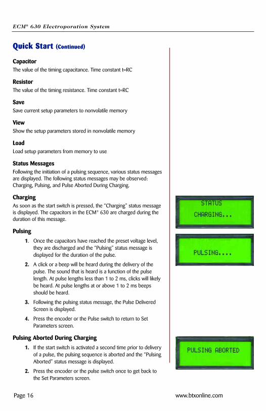
ChargingAs soon as the start switch is pressed, the “Charging” status messageis displayed. The capacitors in the ECM® 630 are charged during theduration of this message.
Pulsing
1. Once the capacitors have reached the preset voltage level, they are discharged and the “Pulsing” status message is displayed for the duration of the pulse.
2. A click or a beep will be heard during the delivery of the pulse. The sound that is heard is a function of the pulse length. At pulse lengths less than 1 to 2 ms, clicks will likely be heard. At pulse lengths at or above 1 to 2 ms beeps should be heard.
3. Following the pulsing status message, the Pulse Delivered Screen is displayed.
4. Press the encoder or the Pulse switch to return to Set Parameters screen.
Pulsing Aborted During Charging
1. If the start switch is activated a second time prior to deliveryof a pulse, the pulsing sequence is aborted and the “Pulsing Aborted” status message is displayed.
2. Press the encoder or the pulse switch once to get back to the Set Parameters screen.
ECM® 630 Electroporation System
Page 17 www.btxonline.com
Quick Start (Continued)
Pulse Delivered Screen
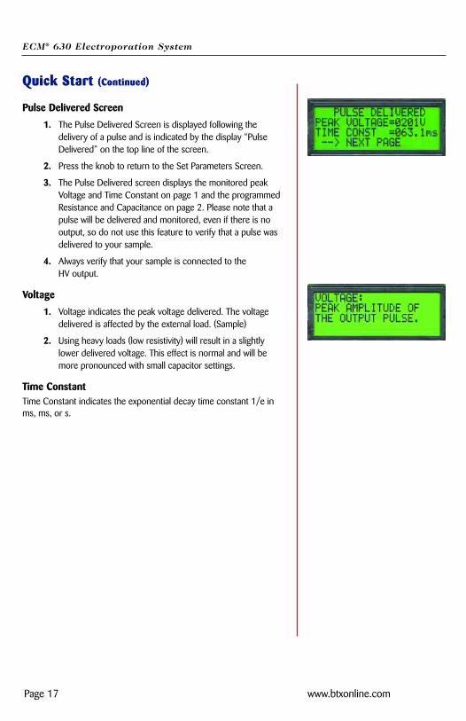
1. The Pulse Delivered Screen is displayed following the delivery of a pulse and is indicated by the display “Pulse Delivered” on the top line of the screen.
2. Press the knob to return to the Set Parameters Screen.
3. The Pulse Delivered screen displays the monitored peak Voltage and Time Constant on page 1 and the programmed Resistance and Capacitance on page 2. Please note that a pulse will be delivered and monitored, even if there is no output, so do not use this feature to verify that a pulse was delivered to your sample.
4. Always verify that your sample is connected to the HV output.
Voltage
1. Voltage indicates the peak voltage delivered. The voltage delivered is affected by the external load. (Sample)
2. Using heavy loads (low resistivity) will result in a slightly lower delivered voltage. This effect is normal and will be more pronounced with small capacitor settings.
Time ConstantTime Constant indicates the exponential decay time constant 1/e inms, ms, or s.
ECM® 630 Electroporation System
Page 18 www.btxonline.com
Operating Basics
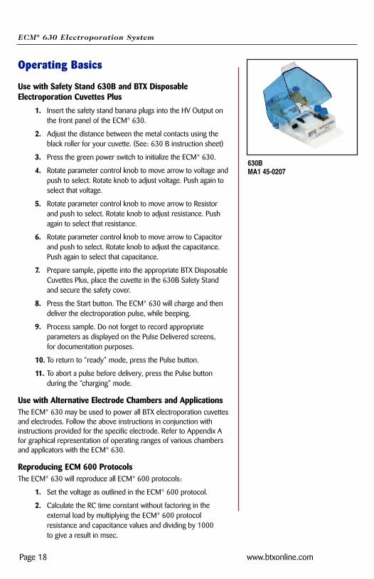
Use with Safety Stand 630B and BTX DisposableElectroporation Cuvettes Plus
1. Insert the safety stand banana plugs into the HV Output on the front panel of the ECM® 630.
2. Adjust the distance between the metal contacts using the black roller for your cuvette. (See: 630 B instruction sheet)
3. Press the green power switch to initialize the ECM® 630.
4. Rotate parameter control knob to move arrow to voltage andpush to select. Rotate knob to adjust voltage. Push again to select that voltage.
5. Rotate parameter control knob to move arrow to Resistor and push to select. Rotate knob to adjust resistance. Push again to select that resistance.
6. Rotate parameter control knob to move arrow to Capacitor and push to select. Rotate knob to adjust the capacitance. Push again to select that capacitance.
7. Prepare sample, pipette into the appropriate BTX DisposableCuvettes Plus, place the cuvette in the 630B Safety Stand and secure the safety cover.
8. Press the Start button. The ECM® 630 will charge and then deliver the electroporation pulse, while beeping.
9. Process sample. Do not forget to record appropriate parameters as displayed on the Pulse Delivered screens, for documentation purposes.
10. To return to “ready” mode, press the Pulse button.
11. To abort a pulse before delivery, press the Pulse button during the “charging” mode.
Use with Alternative Electrode Chambers and ApplicationsThe ECM® 630 may be used to power all BTX electroporation cuvettesand electrodes. Follow the above instructions in conjunction withinstructions provided for the specific electrode. Refer to Appendix Afor graphical representation of operating ranges of various chambersand applicators with the ECM® 630.
Reproducing ECM 600 ProtocolsThe ECM® 630 will reproduce all ECM® 600 protocols:
1. Set the voltage as outlined in the ECM® 600 protocol.
2. Calculate the RC time constant without factoring in the external load by multiplying the ECM® 600 protocol resistance and capacitance values and dividing by 1000 to give a result in msec.
630BMA1 45-0207
ECM® 630 Electroporation System
Page 19 www.btxonline.com
Operating Basics (Continued)
3. Refer to Appendix B. Find the capacitance setting from step 2 and read down the column to find a RC time constant thatclosely matches. Extrapolate the new ECM® 630 resistance setting..
4. Set the capacitance from the ECM® 600 protocol and the new resistance extrapolated from Appendix B.
5. Follow experimental procedures while optimizing the voltageas outlined in Appendix C.
Reproducing Competitive System ProtocolsThe ECM® 630 is capable of reproducing most exponential competi-tive system protocols.
BioRad Gene Pulser® and Gene Pulser® II ProtocolsFor protocols using the Capacitance Extender, Capacitance ExtenderII, or the Capacitance Extender Plus, use the resistance setting“none”, reduce the voltage by 50 V and use the capacitance settingoutlined in the protocol. For protocols using the Pulse Controller,Pulse Controller II, or Pulse Controller Plus, use a capacitance settingof 25 µF, reduce the voltage by 50 V and use the resistance settingsoutlined in the protocol. Optimization of voltage as outlined inAppendix C is recommended. For additional recommendations, pleasecontact BTX Technical Support.
Other Competitive Exponential DecayElectroporator ProtocolsAttempt to identify the resistance and capacitance as well as the volt-age outlined in the protocol. Match these as closely to settings allowedwith the ECM® 630. For low voltage protocols (V </= 500V), if there is no resistance outlined, use the ECM® 630resistance setting “none”. For additional recommendations, pleasecontact BTX Technical Support.
ECM® 630 Electroporation System
Page 20 www.btxonline.com
Advanced Operation: Programming1. Set parameters as outlined in Operating Basics.
2. Once presetting of parameters has been completed, rotate the parameter control knob until the save function has been reached.
3. Press knob in and release. Now rotate to select which program number the chosen settings (see “Preset Parameters” above) should be saved under. Program #1 is reserved for current parameters in active use and cannot be used for pre-set storage.
4. Push and hold knob in, releasing only after a new screen reading “Saved Current Parameters to Set N” is displayed. (N refers to program number designated in step 2)
5. Push the parameter control knob again to return to the Set Parameter Screen.
6. From the Set Parameter Screen, use the parameter control knob to rotate until the load function has been reached.
7. Push the knob in and release. Now rotate to select the appropriate program number.
8. Push and hold knob in, releasing only after a new screen reading “Loaded Set N to Current Parameters” is displayed.
9. Push the parameter control knob again to return to the Set Parameter Screen.
ECM® 630 Electroporation System
Page 21 www.btxonline.com
Electroporation
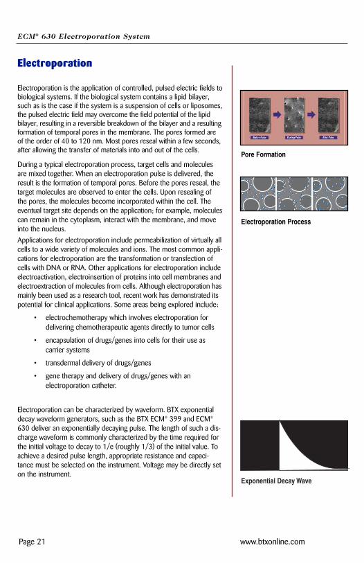
Electroporation is the application of controlled, pulsed electric fields tobiological systems. If the biological system contains a lipid bilayer,such as is the case if the system is a suspension of cells or liposomes,the pulsed electric field may overcome the field potential of the lipidbilayer, resulting in a reversible breakdown of the bilayer and a resultingformation of temporal pores in the membrane. The pores formed areof the order of 40 to 120 nm. Most pores reseal within a few seconds,after allowing the transfer of materials into and out of the cells.
During a typical electroporation process, target cells and moleculesare mixed together. When an electroporation pulse is delivered, theresult is the formation of temporal pores. Before the pores reseal, thetarget molecules are observed to enter the cells. Upon resealing ofthe pores, the molecules become incorporated within the cell. Theeventual target site depends on the application; for example, moleculescan remain in the cytoplasm, interact with the membrane, and moveinto the nucleus.
Applications for electroporation include permeabilization of virtually allcells to a wide variety of molecules and ions. The most common appli-cations for electroporation are the transformation or transfection ofcells with DNA or RNA. Other applications for electroporation includeelectroactivation, electroinsertion of proteins into cell membranes andelectroextraction of molecules from cells. Although electroporation hasmainly been used as a research tool, recent work has demonstrated itspotential for clinical applications. Some areas being explored include:
• electrochemotherapy which involves electroporation for delivering chemotherapeutic agents directly to tumor cells
• encapsulation of drugs/genes into cells for their use as carrier systems
• transdermal delivery of drugs/genes
• gene therapy and delivery of drugs/genes with an electroporation catheter.
Electroporation can be characterized by waveform. BTX exponentialdecay waveform generators, such as the BTX ECM® 399 and ECM®
630 deliver an exponentially decaying pulse. The length of such a dis-charge waveform is commonly characterized by the time required forthe initial voltage to decay to 1/e (roughly 1/3) of the initial value. Toachieve a desired pulse length, appropriate resistance and capaci-tance must be selected on the instrument. Voltage may be directly seton the instrument.
Pore Formation
Electroporation Process
Exponential Decay Wave
ECM® 630 Electroporation System
Page 22 www.btxonline.com
Applications
Electroporation
Bacteria and Yeast ElectroporationThe most common application is transformation. Field strength andpulse length are critical parameters for reporting, optimization andtroubleshooting bacterial and yeast applications.
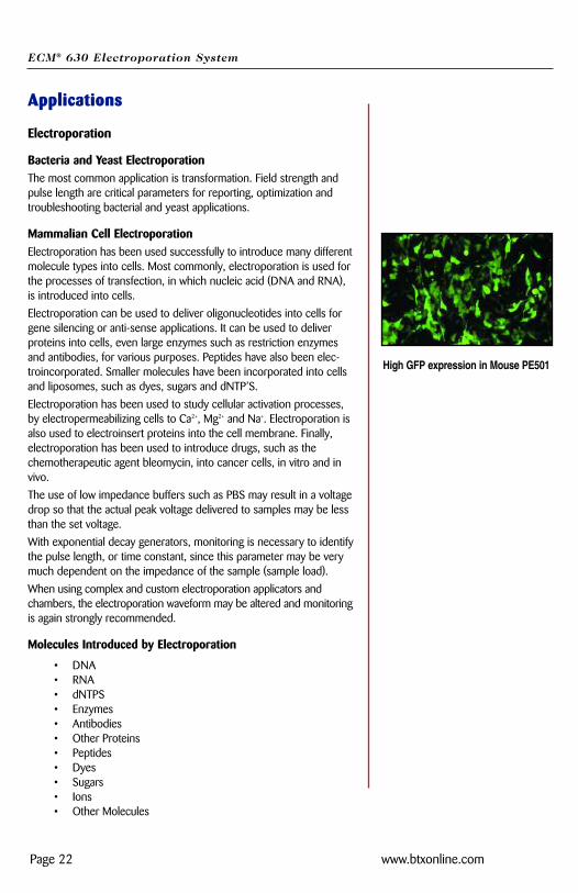
Mammalian Cell ElectroporationElectroporation has been used successfully to introduce many differentmolecule types into cells. Most commonly, electroporation is used forthe processes of transfection, in which nucleic acid (DNA and RNA),is introduced into cells.
Electroporation can be used to deliver oligonucleotides into cells forgene silencing or anti-sense applications. It can be used to deliverproteins into cells, even large enzymes such as restriction enzymesand antibodies, for various purposes. Peptides have also been elec-troincorporated. Smaller molecules have been incorporated into cellsand liposomes, such as dyes, sugars and dNTP’S.
Electroporation has been used to study cellular activation processes,by electropermeabilizing cells to Ca2+, Mg2+ and Na+. Electroporation isalso used to electroinsert proteins into the cell membrane. Finally,electroporation has been used to introduce drugs, such as thechemotherapeutic agent bleomycin, into cancer cells, in vitro and invivo.
The use of low impedance buffers such as PBS may result in a voltagedrop so that the actual peak voltage delivered to samples may be lessthan the set voltage.
With exponential decay generators, monitoring is necessary to identifythe pulse length, or time constant, since this parameter may be verymuch dependent on the impedance of the sample (sample load).
When using complex and custom electroporation applicators and chambers, the electroporation waveform may be altered and monitoringis again strongly recommended.
Molecules Introduced by Electroporation
• DNA• RNA• dNTPS• Enzymes• Antibodies• Other Proteins• Peptides• Dyes• Sugars• Ions• Other Molecules
High GFP expression in Mouse PE501
ECM® 630 Electroporation System
Page 23 www.btxonline.com
Applications (Continued)
Plant Protoplast ElectroporationElectroporation has been used to introduce molecules into plant protoplasts, pollen and most recently, direct transfer into plant tissue (in vivo).
Other Electroporation Applications
1. Transgene incorporation, in which simple transfection of fish embryos has resulted in transgenic zebrafish.
2. Utilization of sperm as biological DNA carriers, in which pulsed fields cause the complexing of DNA to sperm, which then act as carriers upon fertilization.
3. Acrosome enhancement in which an exponential decay pulse enhances the acrosome reaction and facilitates fertilization.
4. Embryonic Stem Cell Chimeras, in which embryonic stem cell transfection, followed by micromanipulation into host blastomere, has resulted in chimeric mice.
5. Parthogenesis, in which a repetitive DC pulse stimulates an unfertilized egg to activate and divide as if fertilized, resultingin haploid and diploid embryos.
ECM® 630 Electroporation System
Page 24 www.btxonline.com
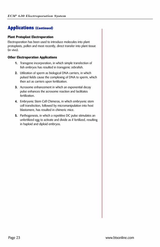
Appendix A: ECM® 630 ElectrodeOperation RangesFigures 1 - 6 display expected operating ranges for the ECM® 630 withvarious chambers and electrodes. The data lines in the following figuresrepresent the arcing boundaries for the given electrode/chambermodel, electroporation media, volume, and voltage/mode. The area atand above each line represents 100% arcing probability. The areabeneath each line represents parameters that may lead to the deliveryof a full pulse. This data was empirically determined in the BTXApplication Laboratory.
Operating Range for 620/PBS/LV
R = 500 ohmC = 1 uF
R = 1575 ohmC = 25 uF
R =25 ohmC= 3275 uF
200
275
350
425
500
575
0.01 0.1 1 10 100
Pulse Length (ms)
Vol
tage
(V
)
620/40 uL PBS 620/400uL PBS
Figure 1Operating Range for the ECM® 630 with Model 620in LV with PBS at various volumes
Operating Range for 640/PBS/LV
R=25 ohmC=3275 uF
R=1575 ohmC=25 uF
R=500 ohmC=1 uF
200
300
400
500
600
0.01 0.1 1 10 100Pulse Length (ms)
Vol
tage
(V
)
640 @ 200 uL 640 @ 400 uL 640 @ 800 uL
Figure 2Operating Range for the ECM® 630 with Model640 in LV with PBS at various volumes
2 mm gap cuvette20 to 500 V25 µsec to 93 msec
4 mm gap cuvette20 to 500 V25 µsec to 70 msec
ECM® 630 Electroporation System
Page 25 www.btxonline.com
Operating Range for PP35/PBS/LV
R =25 ohmC = 3275 uF
R = 1575 ohmC = 25 uF
R = 500 ohmC = 1 uF
200
250
300
350
400
450
500
0.001 0.01 0.1 1 10 100
Pulse Length (ms)
Vol
tage
(V
)
PP35-2 @ 1mL PBS PP35-2 @ 3mL PBS
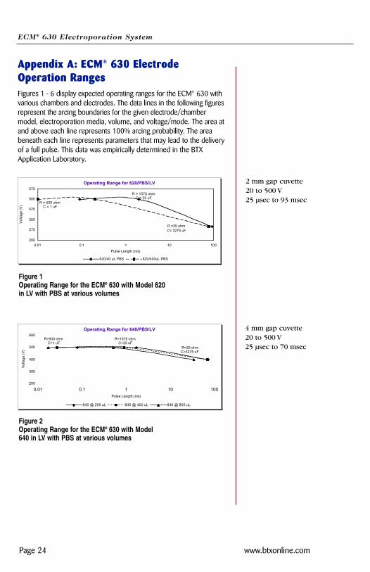
Figure 4Operating Range for the ECM® 630 withPP35 in LV with PBS at various volumes
Petri Pulser20 to 400 V10 µsec to 40 msec
Operating Range for 610/Water/HV
R =25 ohmC = 25 uF
R = 100 ohmC = 50 uF
R=1575 ohmC=25 uF
10001200140016001800200022002400260028003000
0.68 5 36
Pulse Length (ms)
Vol
tage
(V
)
610 @ 50 uL
Figure 5Operating Range for Model 610/H20/HV
1 mm gap cuvette50 to 2500 V680 µsec to 36 msec
Appendix A: ECM® 630 ElectrodeOperation Ranges (Continued)
Operating Range for 366/PBS/LV
R = 25 ohmC =3275 uF
R = 1575 ohmC = 25 uF
200
250
300
350
400
0.01 0.1 1 10
Pulse Length (ms)
Vol
tage
(V
)
366 @ 8 mL 366 @ 15 mL
Figure 3Operating Range for the ECM® 630 with366 in LV with PBS at various volumes
Petri dish electrode20 to 350 V25 µsec to 6 msec
ECM® 630 Electroporation System
Page 26 www.btxonline.com
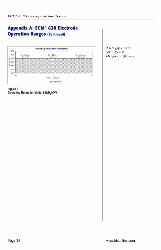
Appendix A: ECM® 630 ElectrodeOperation Ranges (Continued)
Operating Range for 620/Water/HV
R = 1575 ohmC = 25 uF
R = 100 ohmC = 50 uF
R = 25 ohmC = 25 uF
2000
2125
2250
2375
2500
2625
2750
0.66 5 38
Pulse Length (ms)
Vol
tage
(V
)
620 @ 200 uL
Figure 6Operating Range for Model 620/H20/HV
2 mm gap cuvette50 to 2500 V660 µsec to 38 msec
ECM® 630 Electroporation System
Page 27 www.btxonline.com
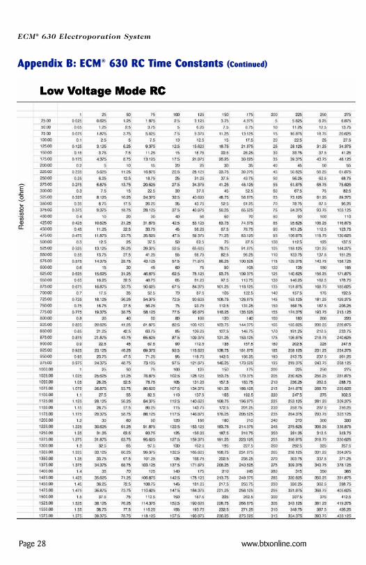
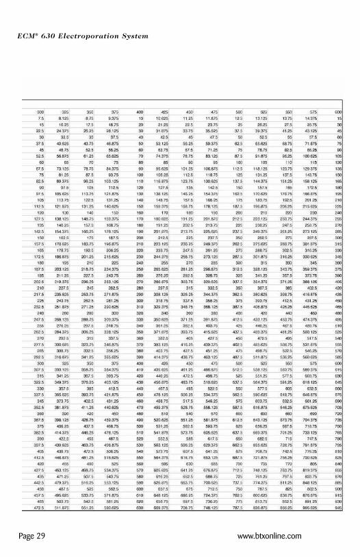
Appendix B: ECM® 630 RC Time ConstantsSEE PAGES 28 - 38
ECM® 630 Electroporation System
Page 28 www.btxonline.com
Appendix B: ECM® 630 RC Time Constants (Continued)
ECM® 630 Electroporation System
Page 29 www.btxonline.com
ECM® 630 Electroporation System
Page 30 www.btxonline.com
Appendix B: ECM® 630 RC Time Constants (Continued)
ECM® 630 Electroporation System
Page 31 www.btxonline.com
ECM® 630 Electroporation System
Page 32 www.btxonline.com
Appendix B: ECM® 630 RC Time Constants (Continued)
ECM® 630 Electroporation System
Page 33 www.btxonline.com
ECM® 630 Electroporation System
Page 34 www.btxonline.com
Appendix B: ECM® 630 RC Time Constants (Continued)

ECM® 630 Electroporation System
Page 35 www.btxonline.com
ECM® 630 Electroporation System
Page 36 www.btxonline.com
Appendix B: ECM® 630 RC Time Constants (Continued)
ECM® 630 Electroporation System
Page 37 www.btxonline.com
ECM® 630 Electroporation System
Page 38 www.btxonline.com
Appendix B: ECM® 630 RC Time Constants (Continued)
ECM® 630 Electroporation System
Page 39 www.btxonline.com
Appendix C: Optimization Strategies
GeneralThe success of electro cell manipulation (ECM) lies in selecting appro-priate ECM systems capable of delivering the pulses suitable for thecell being electromanipulated. One, or several pulses of the appropriatefield strength, pulse length, and wave shape may be required for thispurpose.
The key to success with electroporation-based technologies involvesa proper combination of biological, physical, chemical, and pulseparameters. In general, cells must be in mid-logarithmic growth foroptimal electroporation. Various temperature regimens have beendescribed. It has been shown that a variety of chemical techniquesmay increase electroporation efficiencies, including addition of EDTA,DMSO, intracellular salts, and serum before or after the pulse.Optimizing protocols abound. Analysis of these optimization regimens has lead to proposals of universal protocols,involving very limited optimization over a narrow range.
Electroporation
1. Vary the voltage in order to vary the field strength, keeping other parameters constant. Assay sample for both viability and endpoint. Plot the field strength versus both viability andendpoint and extrapolate the optimal field strength (voltage divided by gap size) and voltage.
2. Vary the capacitance/resistance/sample volume at the optimal voltage setting in order to vary the pulse length (time constant) for exponential decay instruments. Directly vary square wave instrument pulse length. Assay sample for both viability and endpoint. Plot the pulse length versus bothviability and endpoint and extrapolate the optimal pulse length/parameters.
3. For multiple pulsing systems/protocols, vary the number of pulses at the optimal field strength and pulse length. Assay sample for both viability and endpoint. Plot the number of pulses versus both viability and endpoint, and extrapolate the optimal number of pulses.
ECM® 630 Electroporation System
Page 40 www.btxonline.com
Appendix D: Electrical Troubleshooting
Instrument Does Not Power UpVerify that the power cord is fully inserted in the instrument and in thewall outlet. Verify that the fuse is not blown. Disconnect power cordfrom the instrument before removing the fuse holder. Replace thefuse, if necessary, with same rated fuse as indicated on back panel.
Unanticipated RC time constants or peak voltage outputUn-anticipated RC time constant or peak output voltage may be a signthat appropriate capacitors are not being selected or are not fullycharging. Please remember that the external load (sample) reducesthe expected time constant and voltage to various degrees. If youbelieve there is a problem, contact BTX Technical Support for immediate consultation.
LCD Error MessagesThe ECM® 630 is constantly monitoring the parameters of some of itsinternal circuitry. In the case of a malfunction, one of the followingmessages will appear on the display. Note the instructions on the following pageused to confirm the absence of a pulse. In this case,call BTX Technical Support.
EEPROM FailureThe unit has detected a malfunction in its internal memory system.The validity of the data might be compromised. Turning or pressingthe knob will bring the Set Parameters screen. Verify carefully everysetpoint before pulsing. This verification is performed during powerup and every time that data is loaded from memory. Contact BTXTechnical Support if this error message is displayed again, after apower up sequence.
Pulsing Aborted Charge FailureThe unit did not charge its selected capacitor bank. Turn or press theencoder knob. Disconnect the load from the HV connector. Select adifferent capacitor and press the pulse button. Contact BTX® TechnicalSupport if a similar message is displayed again.
Pulsing Aborted Charging Timed OutA charging time limit of 20 seconds is provided for circuit safety. Ifthe capacitors are not charged to the pre-set voltage level after 20seconds, the “PULSING ABORTED CHARGING TIMED OUT” mes-sage is displayed. For assistance with this situation, please contactBTX Technical Support. Press the encoder or the pulse switch once toget back to the Set Parameters screen.
ECM® 630 Electroporation System
Page 41 www.btxonline.com
Appendix E: ExperimentalTroubleshooting
ArcingVerify electrical component functionality. Verify properties of cellsample (do cells need to be washed? Is the buffer appropriate forapplication?). Verify properties of transfectant/molecule (Is the DNAwell purified?) Try reducing the voltage or increase sample volumeuntil arcing is no longer a problem.
Low (or no) transfection efficiency, or incorporationVerify physical, biological, and chemical parameters. Verify delivery ofthe pulse and pulse parameters. Is the voltage correct? Chamber gap?Pulse length or appropriate instrument settings? Number of pulses? Ifso, follow Optimization Guidelines outlined in Appendix A.
Low viabilityVerify physical, biological, and chemical parameters. Are the voltage,chamber gap, pulse length (time constant), pulse number and otherinstrument settings correct? If so, reduce voltage, pulse length, ornumber of pulses and re-optimize protocol to improve viability as out-lined in Appendix A.
ECM® 630 Electroporation System
Page 42 www.btxonline.com
Appendix F: Glossary of Electrical Terms
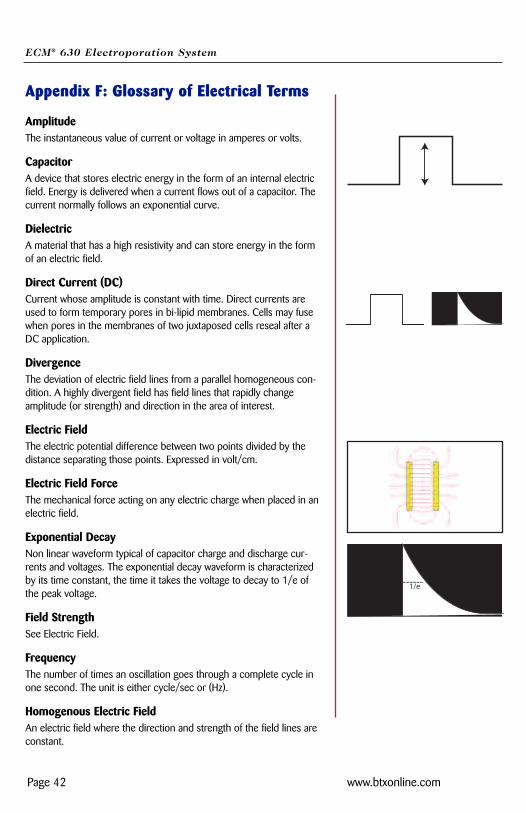
AmplitudeThe instantaneous value of current or voltage in amperes or volts.
CapacitorA device that stores electric energy in the form of an internal electricfield. Energy is delivered when a current flows out of a capacitor. Thecurrent normally follows an exponential curve.
Dielectric A material that has a high resistivity and can store energy in the formof an electric field.
Direct Current (DC)Current whose amplitude is constant with time. Direct currents areused to form temporary pores in bi-lipid membranes. Cells may fusewhen pores in the membranes of two juxtaposed cells reseal after aDC application.
DivergenceThe deviation of electric field lines from a parallel homogeneous con-dition. A highly divergent field has field lines that rapidly changeamplitude (or strength) and direction in the area of interest.
Electric Field The electric potential difference between two points divided by thedistance separating those points. Expressed in volt/cm.
Electric Field ForceThe mechanical force acting on any electric charge when placed in anelectric field.
Exponential DecayNon linear waveform typical of capacitor charge and discharge cur-rents and voltages. The exponential decay waveform is characterizedby its time constant, the time it takes the voltage to decay to 1/e ofthe peak voltage.
Field StrengthSee Electric Field.
FrequencyThe number of times an oscillation goes through a complete cycle inone second. The unit is either cycle/sec or (Hz).
Homogenous Electric FieldAn electric field where the direction and strength of the field lines areconstant.
------1/e
ECM® 630 Electroporation System
Page 43 www.btxonline.com
Appendix G: Glossary of Biological &Technical Terms
ChambersElectroporation and Electrofusion Chambers are the devices used tohold the cells/molecules to be fused/transfected.
Dielectric BreakdownThe reversible breakdown of lipid bilayer membranes as a result of theapplication of a DC electroporation pulse. Sufficiently high fieldstrength may increase the membrane potential past a critical pointleading to the breakdown of the membrane.
DielectrophoresisA consequence of cells being exposed to an inhomogeneous or diver-gent electric field, resulting in their movement toward electrodes, andsubsequent alignment or pearl chain formation.
ElectroinsertionThe use of electroporation to insert molecules into lipid bilayermembranes.
ElectropermeabilizationThe use of electroporation to make cells, protoplasts, or liposomes per-meable to ions and small molecules in their extracellular environment.
ElectroporationThe application of high electric field pulses of short duration to createtemporary pores (holes) in the membranes of cells.
Hydrostatic PressureThe pressure in liquids at rest.
Lipid BilayerAn assembly of lipid and protein molecules held together by non-covalent interactions. All biological membranes share thiscommon structure.
Osmotic PressureThe applied pressure required to prevent the flow of solvents ofdifferent concentration across a semipermeable membrane.
PoreA small, mostly transient, opening in a cell wall caused by the application of a brief high electric field pulse.
Pressure GradientThe difference in pressure between two points in a medium.
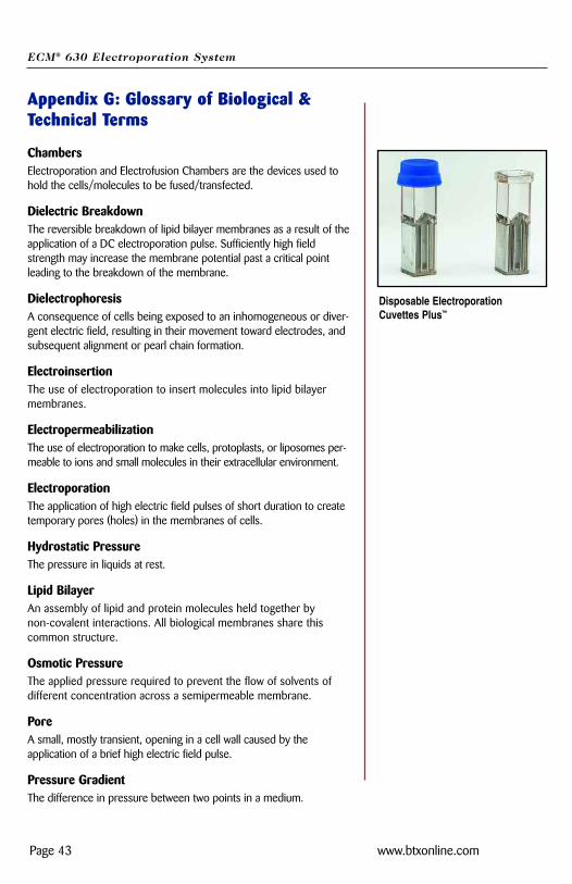
Disposable ElectroporationCuvettes Plus™
ECM® 630 Electroporation System
Page 44 www.btxonline.com
Appendix G: Glossary of Biological &Technical Terms (Continued)
ProtoplastsThe plant cell proper, with the cellulose cell wall removed.
Relaxation TimeThe time a system requires to reach equilibrium.
TransfectionThe introduction of nucleic acids into animal cells. Stable transfectionsresult in integration of nucleic acids into host chromosomes and theinheritance of associated traits in progeny cells. Transient transfectionsresult in temporary expression of exogenous nucleic acids.
TransformationThe introduction of nucleic acids into microorganisms and plant cells.
Turgor PressureThe pressure in capillaries.

ECM® 630 Electroporation System
Page 45 www.btxonline.com
Appendix H: Electroporation PulseGenerator Compatibility Certain components of BTX Electroporation are compatible with com-ponents of competitive systems. Please contact BTX Technical Support for details.
ECM® 630 Electroporation System
Page 46 www.btxonline.com
Appendix I: Recommended ReadingEberhard Neumann, Editor, Electroporation and Electrofusion in CellBiology, Plenum Publishing Corporation, 1989
Michael Kriegler, Gene Transfer and Expression, A Laboratory Manual,Stockton Press, 199
Donald Chang, Editor-in-Chief, Guide to Electroporation andElectrofusion, Academic Press, 1992
Jac A. Nickoloff, Editor, Electroporation Protocols for Microorganisms,in Methods in Molecular Biology, Vol 47, Humana Press, 1995
Jac A. Nickoloff, Editor, Animal Cell Electroporation and ElectrofusionProtocols, in Methods in Molecular Biology, Vol 48, Humana Press,1995
Jac A. Nickoloff, Editor, Plant Cell Electroporation and ElectrofusionProtocols, in Methods in Molecular Biology, Vol 55, Humana Press,1995
For further references regarding specific applications and optimiza-tion, please contact BTX Technical Support:
BTX-Division of Harvard Apparatus
84 October Hill Road
Hollistion, MA 01746
Phone: 1-508-893-8999
Toll Free: 1-800-272-2775
Fax: 1-508-429-5732
Email: [email protected]
Website: www.btxonline.com
ECM® 630 Electroporation System
Page 47 www.btxonline.com
Appendix J: Accessories and ReplacementParts
Catalog No. Model Description
MA1 45-0001 6300 ECM® 630 Electroporation System
MA1 45-0051 630 ECM® 630 Electroporator only
MA1 45-0207 630B Electroporation Safety Stand
MA1 45-0124 610 Disposable Electroporation Cuvettes Plus, 1mm, 50 per bag
MA1 45-0125 620 Disposable Electroporation Cuvettes Plus, 2 mm, 50 per bag
MA1 45-0126 640 Disposable Electroporation Cuvettes Plus, 4 mm, 50 per bag
ECM® 630 Electroporation System
Page 48 www.btxonline.com
Appendix K: General Care and Cleaning
General CareDo not store or leave the instrument where the LCD display will beexposed to direct sunlight for long periods of time.
CAUTIONTo avoid damage to the instrument, do not expose tosprays, liquids, or solvents.
CleaningInspect the instrument, as often as operating conditions require. Toclean the instrument exterior, perform the following steps:
1. Remove loose dust on the outside of the instrument with a lint-free cloth. Use care to avoid scratching the clear plastic display filter.
2. Use a soft cloth dampened with water to clean the instrument. Use an aqueous solution of 75% isopropyl alcohol for more efficient cleaning.
CAUTIONTo avoid damage to the surface of the instrument, donot use any abrasive or chemical cleaning agents. Use caution not to drop or cause any unwarranted physical harm to the instrument during any cleaning operations.