Embed Size (px)
Citation preview

Edelstahl Witten-KrefeldEdelstahlwerke Südwestfalen
Hot-work tool steels
Edelstahl Witten-KrefeldEdelstahlwerke SüdwestfalenContacts
Sales + Customer ServicesHot-work tool steel Tel. +49 2302 - 294 223Fax +49 2302 - 294 508E-mail: [email protected]
Edelstahl Witten-Krefeld [email protected] www.ewk-stahl.comEdelstahlwerke Südwestfalen [email protected] www.ews-stahl.de

Contents
04
05
06
08
09
09
10
11
12
14
15
16
18
19
20
22
23
24
26
27
28
30
31
32
60
68
Tool steels made from hot-work tool steels
Edelstahl Witten-Krefeld and Edelstahlwerke Südwestfalen the hot-work tool steel experts
Process reliability from consultation through to the final product
Our technology and experience your guarantors for premium quality
Custom remelting
Tailor-made heat treatment
Hot-work tool steels for various manufacturing processes
Overview of hot-work tool steels
Pressure die casting
Properties and applications of pressure die casting steels
Steels for pressure die casting
Extrusion
Properties and applications of extrusion steels
Steels for extrusion
Drop forging
Properties and applications of drop forging steels
Steels for forging
Glass product manufacturing
Properties and applications of glass product manufacturing steels
Steels for glass product manufacturing
Tube manufacturing
Properties and applications of tube manufacturing steels
Steels for tube manufacturing
Material data sheets
Notes on processing
Hardness comparison table
02 03
Drop forging
The significance of tool steelsextends far beyond what isgenerally perceived as commonplace. Nearly all theobjects we are surrounded byand encounter on a daily basisare manufactured with the helpof tool steels.
The application spectrum forhot-work tool steels is extensiveand the tools manufactured areused in the most diverse areas.These steels enable the hot-forming of workpieces made ofiron and non-ferrous metals aswell as alloy derivatives at hightemperatures. They are utilizedin processes such as pressure diecasting, extrusion and drop forging as well as in tube andglass manufacturing.
When used, hot-work tool steel products are mainly exposed tohigh temperatures exceeding200 °C. Since microstructuraltolerances are minimal, themicrostructure of these steelshas to be sufficiently stable andresistant to tempering.
Tools made from hot-work toolsteels are not only subject toconstantly high temperatureswhen employed, but also to fluctuating thermic loads occurring where the tool surfacescome into contact with thematerials to be processed.Combined with the wear caused by abrasion or impact,these thermic loads constitutevery specific requirements onthe hot-work tool steels. Keydemands are high temperingresistance, temperaturestrength, thermal shock resistance, high-temperaturetoughness and wear resistance.
Tool steels made fromhot-work tool steels
Edelstahl Witten-Krefeld and Edelstahlwerke Südwestfalenhot-work tool steel experts
Fulfilling all the qualities required of one and the samesteel grade simultaneously andequally is, from a practical pointof view, hardly possible. Thevery varying demands madefrom one tool to the next,where steel grades using a specific alloy segment as arequirement cannot, from a scientific viewpoint, be realized. Steel grades thereforehave to be chosen according to the foremost demands of the tool to be employed.
The use of high-quality hot-work tool steels is imperative to ensure an optimal degree ofoperational efficiency and highproductivity.
The Edelstahl Witten-Krefeld andEdelstahlwerke Südwestfalenhot-work tool steels are characterized by high durabilityand can be individually andeffectively matched with themost diverse requirements of a tool or processing method.
By applying cutting-edge technology, Edelstahl Witten-Krefeld and EdelstahlwerkeSüdwestfalen’s hot-work toolsteels meet the most rigorousdemands on:
• tempering resistance• thermal shock resistance• temperature strength• high-temperature toughness• high-temperature wear
resistance• resistance to erosion, high-
temperature corrosion andoxydation
• machinability• low adhesion tendency
So as to offer the very bestpre-requisites relating to thespecific demands of tool manufacturers, the processingand manufacturing industriesas well as other industrial users,Edelstahl Witten-Krefeld andEdelstahlwerke Südwestfalenhave extended their servicesinto customer and application-specific consultancy as well asproviding advice on productdevelopment.
04 05
Forging die Arc furnace
Process reliability from consultation through to the final product
Square shapes can likewise bechamfered or ground.Rotationally symmetrical partswith individual pieces weighingup to 15 tons are manufacturedin modern rolling and forgingunits. Machining is then possibleon turning, grinding and millingequipment. Products originatingfrom the tools and mouldmanufacturing sector are madeusing state-of-the-art machineryin our Witten works.
Edelstahl Witten-Krefeld andEdelstahlwerke Südwestfalen'sbroad machining and productranges span from pre-milledingots via precision flats andsquares to ready-made singleparts of up to 40 tons in weight.On request, parts will be pre-machined up to 0.3 mm to thefinished contour. Tailor-madesolutions for our clients extendfrom the pre-machining of products including the manufacture of components, toperfectly fitting pre-machinedparts (e.g mandrels), as well asthe complete pre-machining ofouter contours including heatand surface treatment.
QualitySo as to guarantee consistencyand reproducible quality, weuse our active and certifiedquality assurance system comprising DIN EN 14001, DINEN ISO 9001, QS 9000, VDA 6.1TS 16949, KTA 1401.All our manufacturing processesare monitored and supervisedfrom smelting to castingthrough to the ensuing testingof internal and surface flaws,including identity tests of theproducts machined in our rolling mill finishing lines.
Our control system is alsoapplied to the technological andmechanical testing of samples.The fact that we have beengranted all the importantlicenses from the automobileindustry (CNOMO, GM and FORD) as well as those from otherdistinguished institutions suchas the VDG, DGM and NADCA,clearly indicates that our clientscan rely on the quality we provide.
Resistance to thermal shockThe ability of hot-work toolsteels to cope with recurringtemperature changes withoutsurface damage is of particularimportance.Compared to other steels, thehigher proportion of alloysensures optimum toughnessand thermal shock resistance.At one of Edelstahl Witten-Krefeld and EdelstahlwerkeSüdwestfalen laboratories,we carry out research to find superior componentcombinations exhibiting thevery best material qualities.Purpose-built for simulatingthermal shock, tests are conducted to establish theinfluence of extremly rapidtemperature changes – well inexcess of 500 °C – on diversesteel grades. The expertise gained from these tests is directed toward the on-goingdevelopment and production of even better hot-work toolsteels.
Extensive product range and stockEdelstahl Witten-Krefeld andEdelstahlwerke Südwestfalen deliver customized sizes fromstock and within very
favourable delivery times. Ourbroad range of tool steels enables us to easily fulfil anyquality requirements.Furthermore, at any one timewe have around 20,000 tons oftool steels in several thousandsizes at our disposal.
And it goes without saying thatwe manufacture any special products needed as feedstock intool production.
Steel production – under one roofFrom consultancy through tosteel production, heat treatmentand client-specific machiningthrough to world-wide delivery– our precision is a guaranteedone-stop solution. This meansyou always enjoy the benefit ofoverseeing the constant degreeof precision employed in whichever tool or processingmethod you have selected.
World-wide availabilityYou will find our marketingcompanies and representativeoffices in all of the world'simportant markets.Wherever on this planet a chosensteel is needed – our global supply network guaranteesdependable delivery,promptness and permanentlyconsistent quality.
06 07
Depending on their application,tools made from hot-work toolsteels have to fulfil a plethoraof requirements. To ensure theideal practical solution, it shouldbe considered that the correctchoice and treatment of a steelgrade play an all-important roleon the steel’s quality and resulting operational efficiency.
Technical consultancy Advisory competence for ourclients ranges from the choiceof the most suitable steel gradevia queries about heat treatmentthrough to the tailor-madedevelopment of a specific toolsteel grade. The know-how weshare with our customers ontechnical issues offers utmostproduction assurance rightfrom the start. In this way, all production-relevant factors canbe smoothly co-ordinated in therun-up to production, resulting incost minimization.
Our technicians and materialspecialists provide advice andsupport even when problemswith the tool’s service life occur.Through assessment and material testing, they are in theposition to produce findingswhich lead to rapid repairs enabling long-term trouble-freeoperation.
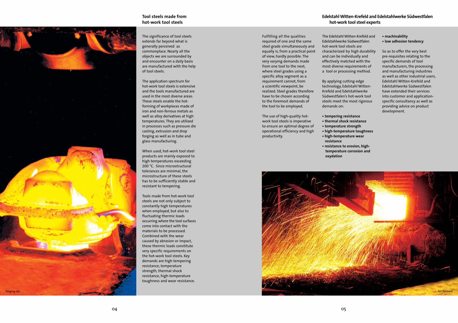
Machining and serviceOur highly efficient team andultra-modern machine toolsguarantee a flexibility andswiftness necessary to realizepractically all clients demands.Our flexibility enables, forinstance, the straightening ofrolled or forged bar steel whichcan then be peeled or turned,pressure-polished and chamfered.
Forged products

The purity and homogeneity ofour hot-work tool steels stemsfrom producing them in ourmodern steelworks at Wittenand Siegen. We fulfil our clients' predefined demands by meansof precision alloying and usingprocess specifications for melting, shaping and heattreatment.
The tool steels produced byEdelstahl Witten-Krefeld andEdelstahlwerke Südwestfalenare melted in 130-ton electricarc furnaces. A subsequentanalytical fine-tuning is carriedout in a ladle furnace, followedby vacuum degassing of thesteel just before casting.
In order to cast the metallurgically treated moltenmetal, two processes can beapplied depending on therequired size of the final product. Usually a bow-typeand optimized vertical continuous casting method isused, but for large forging sizes,ingot casting is employed.
Our technology and experienceyour guarantors for premium quality
Tailor-made heat treatmentCustom remelting
With tool steels having to satisfy especially high levels oftoughness, homogeneity andpurity standards, EdelstahlWitten-Krefeld andEdelstahlwerke Südwestfalenhave five electroslag remeltingfurnaces (ESRs) and one vacuum-arc remelting furnace(VAR) at their disposal.
The decision as to which process and furnace to use is predetermined by the desiredquality the remelted steelshould have. Electroslag remelting (ESR) produces noticeably refined sulfidic purityin comparison to non-remeltedsteel. To improve oxidic purity,vacuum-arc remelting (VAR) isemployed.
Thanks to computer-controlledprocess flows, the reproducibilityof the heat treatment is guaranteed at any time – fromthe initial inspection of incomingshipments through to the finalheat-treated product.
A bonus for our clientsThrough the use of a precision-hardening process – anEdelstahl Witten-Krefeld development – we are in theposition to reduce the deformation of guide strips to a minimum.
08 09
The integration of the previousThyssen hardening shops into the Edelstahl Witten-Krefeld and EdelstahlwerkeSüdwestfalen group has enabled us to build on decadesof tradition in all fields of heattreatment. From a practicalpoint of view, we are now ableto manufacture products usingthe complete production chain –starting with steel production,via pre-machining to refiningthrough to heat treatment. Ourone-stop solution is invaluablefor the world's most importantmarkets and facilitates fulfilment of the mostdiscerning tool quality prerequisites.
In our hardening shops acrossthe continents, we have vacuum-tempering furnaces, inert gasplants and plasma-nitridingplants for thermo-chemical treatments at our disposal.
ESR furnace at Krefeld factory Plasma nitriding
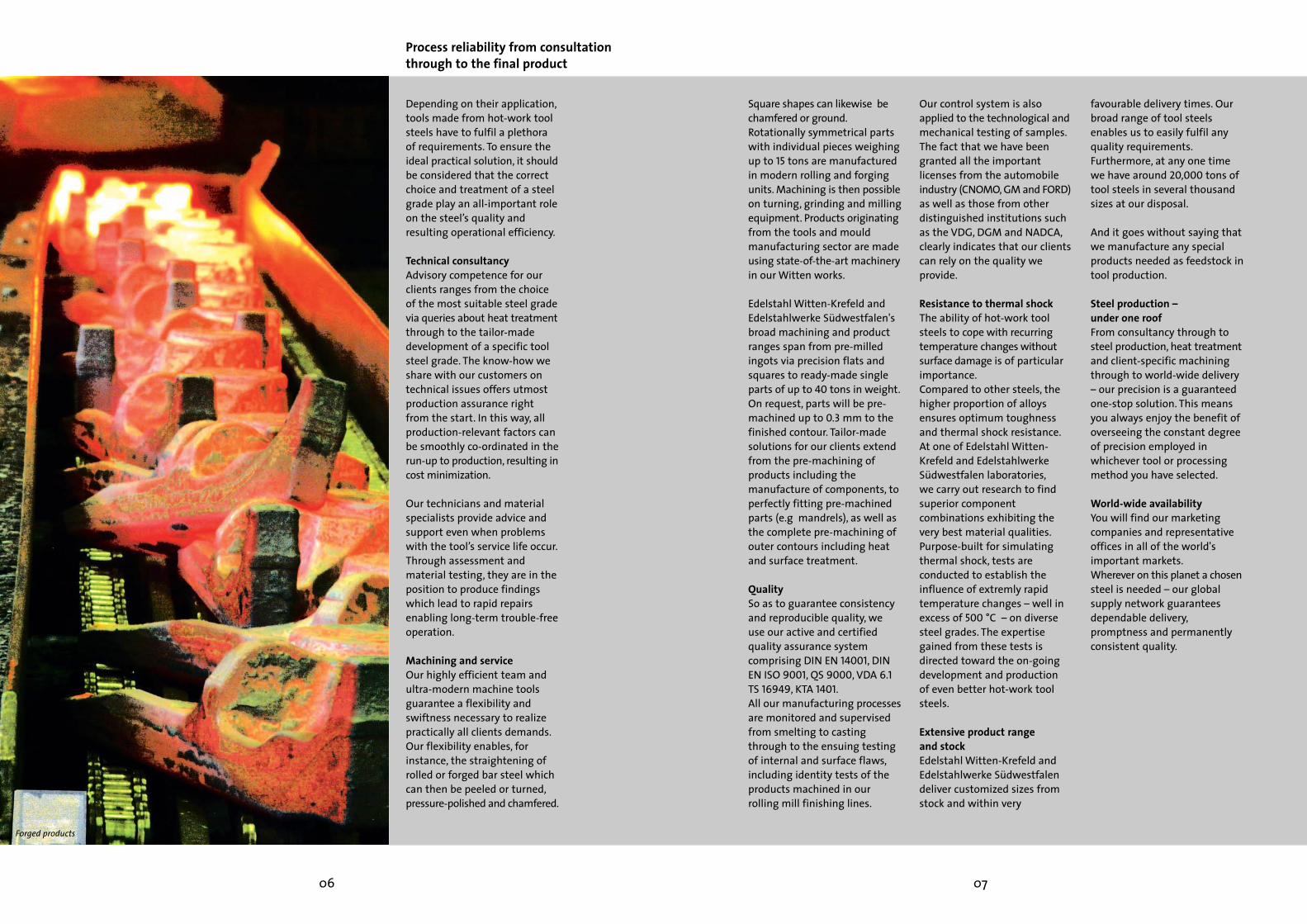
A hot-work tool steel's functionality is defined by its chemical composition, thetechnology applied during production and by the ensuingheat treatment. The correctchoice and application of a steelgrade by the user will result in considerable cost savings andincreased production reliability.
Edelstahl Witten-Krefeld andEdelstahlwerke Südwestfalen supply excellent hot-work tool steels for every type of manufacturing process and, soas to meet superior demands,such steels require special heattreatment. Edelstahl Witten-Krefeld and EdelstahlwerkeSüdwestfalen categorize theseproducts with the suffix EFS(extra-fine structure). In themost critical of cases, EFS steelsare additionally re-melted anddepending on the particularprocess applied, the suffixSUPRA or Vakumelt will beincluded.
On the following pages Edelstahl Witten-Krefeld andEdelstahlwerke Südwestfalen'smost important and appropriatesteel grades are representedaccording to their applicationsand the processing methodsinvolved. The steels mentionedbelow are especially recommended for the followingprocesses:
• pressure die casting• extrusion• forging• glass processing• tube manufacturing
Hot-work tool steels for various manufacturing processes
10 11
Forged products
Mandrel
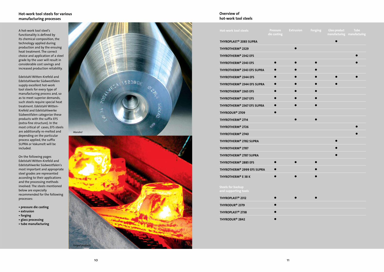
Hot-work tool steels
THYROPLAST® 2083 SUPRA
THYROTHERM® 2329
THYROTHERM® 2342 EFS
THYROTHERM® 2343 EFS
THYROTHERM® 2343 EFS SUPRA
THYROTHERM® 2344 EFS
THYROTHERM® 2344 EFS SUPRA
THYROTHERM® 2365 EFS
THYROTHERM® 2367 EFS
THYROTHERM® 2367 EFS SUPRA
THYRODUR® 2709
THYROTHERM® 2714
THYROTHERM® 2726
THYROTHERM® 2740
THYROTHERM® 2782 SUPRA
THYROTHERM® 2787
THYROTHERM® 2787 SUPRA
THYROTHERM® 2885 EFS
THYROTHERM® 2999 EFS SUPRA
THYROTHERM® E 38 K
THYROPLAST® 2312
THYRODUR® 2379
THYROPLAST® 2738
THYRODUR® 2842
Overview of hot-work tool steels
Pressuredie casting
Extrusion
••••••••
•••
••••
•
•••••••
•
•
•
•
Forging Glass productmanufacturing
Tubemanufacturing
•
••
•••
••
•
••
•••••••
•
•••
•Steels for backupand supporting tools

Pressure die casting
12 13
Pressure die casting is one ofthe most cost-effective manufacturing processes usedby the foundry industry and isrenown for its high dimensionalaccuracy and homogeneityduring series production.
In this process molten metal isinjected into a die cavity at highspeed. The pressure applied totransport the molten metalstream into the narrowest cross-section of the die is decisive forconformal shape reproduction –a major advantage of pressuredie casting.
Thin walls are preferred in theconstruction of die castings,enabling shorter cycle timesand thereby minimizing thedie's thermic load. Neverthelessthe mechanical and thermicloads are considerable duringdie casting. In practice, the service life of the die is ofexceptional importance andfundamentally dependent onthe quality of the hot-work toolsteel used, its production andheat treatment. It should not beunderestimated how paramount the final choice ofthe appropriate steel and the proportional adjustment of anindividual alloy are on the die'squality, reliability and servicelife.
During pressure die casting,temperature differences areimmense and temperaturechange intervals extremelyshort and, depending on themetal used, both can fluctuateconsiderably. This makes the hot-work tool steel's thermal shockresistance an all-importantissue to the die caster.
All in all the steel should displaythe following properties:
• high thermal shock resistance• high temperature strength • good high-temperature
toughness• good thermal conductivity• good high-temperature wear
resistance• high compression strength
Regardless which machine isused to work a specific material,Edelstahl Witten-Krefeld andEdelstahlwerke Südwestfalenensure you receive high performance steels – productswhich set global standards forhot-work tool steel.
Benefits for the tool manufacturer• deadline reliability • quality consistency• cost-effective machinability• uncomplicated heat
treatment• good repair weldability • competent consultancy• short delivery times
Benefits for the die caster• long service life• low die costs• minimal unit costs • low susceptibility to hot
cracking • low repair frequency • good repair weldability • low tool turnover• technical consultancy• dimensional stability
Benefits for the user• long service life• low component costs• reproducible die casting
quality • technical consultancy
Four-cylinder crank case made by HONSEL GMBH & CO. KG

Properties and applications of pressure die casting steels
Steels for pressure die casting
14 15
THYROTHERM® 2344 is a versatilederivative of THYROTHERM® 2343featuring increased temperaturestrength and better high-temperature wear resistance.This facilitates the employmentof THYROTHERM® 2344 withsmall and middle-sized dies forthe production of light-metaldie castings.
THYROTHERM® 2367 not onlycombines the advantageous properties of THYROTHERM®2343 and THYROTHERM® 2344,but shows even better temperature strength and stability. Its high resistance tothermal shock and outstandingtempering strength are decisivereasons to use THYROTHERM®2367 in the production of light-metal die castings frequentlysubjected to high temperatures.
THYROTHERM® 2343 is an all-purpose hot-work tool steelwhich has proven highly successful with large-sized diesfor the processing of lightmetal alloys on account of itshigh toughness potential. It isalso used for forging dies, shrinkrings and hot-shear blades.THYROTHERM® 2343's core properties are its toughness,high temperature strength,good thermal conductivity andinsusceptibility to hot cracking.
THYROTHERM® E 38 K is another hot-work tool steel allrounder. In comparison to THYROTHERM® 2343, it showsimproved toughness and can be utilized with large-dimensionpressure casting dies.
Edelstahl Witten-Krefeld andEdelstahlwerke Südwestfalen offer a broad spectrum ofhomogenous steels for pressurecasting dies. We recommendthe high-performance steelsfrom our THYROTHERM® SUPRArange for dies requiring a maximum service life, reliabilityand cost effectiveness.We have highlighted the following steel grades as mostrepresentative of our completerange.
Die castings for model building and the automotive industry
Toolsfor Al/Al alloys, Zn/Sn,Pb alloysHolding blocks
Cavity inserts, core-slides, cores
Orifices, shot sleeves
Ejectors
Grade
THYRODUR® 1730THYROPLAST® 2312THYROTHERM® 2343 EFS SUPRATHYROTHERM® 2344 EFS SUPRATHYROTHERM® 2367 EFS SUPRATHYROTHERM® E 38 KTHYROTHERM® 2343 EFS SUPRATHYROTHERM® 2344 EFS SUPRATHYROTHERM® 2367 EFS SUPRATHYROTHERM® 2344 EFS SUPRA
Working hardness in HRC (typical values)
(approx. 650 N/mm2)(approx. 1000 N/mm2)
44 – 4844 – 4644 – 4644 – 4844 – 4844 – 4644 – 4644 – 48
Grades for holding blocks and for parts of dies coming into contact with metal
Toolsfor Cu/Cu alloys Holding blocksCavity inserts, core-slides, cores
Orifices, shot sleeves
Ejectors
Grade
THYROPLAST® 2312THYROTHERM® 2365 EFS SUPRATHYROTHERM® 2367 EFS SUPRATHYROTHERM® 2885 EFS THYROTHERM® 2999 EFS SUPRATHYROTHERM® 2365 EFS SUPRATHYROTHERM® 2367 EFS SUPRATHYROTHERM® 2999 EFS SUPRATHYROTHERM® 2344 EFS SUPRA
Working hardness in HRC (typical values)(approx. 1000 N/mm2)
38 – 4338 – 4338 – 4338 – 4338 – 4338 – 4338 – 4344 – 48
Grades for holding blocks and for parts of dies coming into contact with metal
Grade
THYROTHERM® 2343 EFS SUPRATHYROTHERM® 2344 EFS SUPRATHYROTHERM® 2365 EFS SUPRATHYROTHERM® 2367 EFS SUPRATHYROTHERM® 2885 EFSTHYROTHERM® 2999 EFS SUPRATHYROTHERM® E 38 K
Wear resistance
+++++++++
+++++
Toughness
++++
++++
+++
Thermal conductivity
++
+++++
++++++
+
Insusceptibility tohot-cracking
++
++++++
++++
Group-specific property comparisons

Extrusion is a hot-forming process enabling the manufacture of full and hollowprofiles by forcing a pre-heatedslug under high hydraulic pressure through an extrusiondie. The higher the workingtemperature of the slug, thelower the pressure needed forextrusion.The extrusion die should ideallywithstand strain resulting fromhigh working temperatures,abrasion and pressure for aslong as possible.
Subsequently during extrusion,the die's dimensional stabilityand shape retention are crucialfor the production of precisionprofiles or for other products ofconsistent high quality. Hencetemperature strength and high-temperature wear resistanceare the main criteria these toolsteels have to fulfil.
Edelstahl Witten-Krefeld andEdelstahlwerke Südwestfalen's THYROTHERM® EFS and EFSSUPRA high-quality hot-work toolsteels completely fulfil these requirements, ensuring remarkably long service lives anddimensional stability. Thanks to the superior steel quality,the employment of individually forged discs becomes redundant,resulting in considerable costsavings.
Extrusion
16 17
Benefits for the tool manufacturer• deadline reliability• consistent quality • cost-effective machinability • uncomplicated heat treatment• good repair weldability • competent consultancy• short delivery times• joint material development
Benefits for the die caster• long service life• outstanding dimensional
stability• minimal unit cost per die• low repair frequency • good repair weldability • low tool turnover• technical consultancy
Aluminium profiles Aluminium profiled window frames

Properties and applications of extrusion steels
Steels for extrusion
THYROTHERM® 2344 is a hot-work tool steel covering a broadapplication field. Due to superiortemperature strength and high-temperature wear resistance incomparison to THYROTHERM®2343, this grade is especially useful for smaller and middle-sized extrusion dies.THYROTHERM® EFS SUPRA (ESU)is recommended for largerdimension dies and where greater toughness is required.
THYROTHERM® 2329 is an evenmore refined steel for pressuredies and other backup tools. It ischaracterized by amelioratedworkability, especially duringtorch cutting.
18 19
THYROTHERM® 2343 is a universal hot-work tool steelwhich on account of its high-level toughness potential hasbeen particularly successful forlarger-dimension extrusion dies.THYROTHERM® 2343 boastsexcellent properties includingits high temperature strengthand toughness as well as goodthermal conductivity and insusceptibility to hot cracking.For larger dimensions necessitating increasedtoughness we recommend THYROTHERM® EFS SUPRA(ESU).
THYROTHERM® E 38 K is usedfor profiles with particularlycomplex geometries.
Edelstahl Witten-Krefeld provides a broad spectrum of homogenous steels for extrusion.We have highlighted the following steel grades as mostrepresentative of our completerange.All the steels referred to can bequenched and tempered to adesirable working hardness andare recommended for bridgetools, which are used in themanufacturing of light-metaltubes and tubular sections,extrusion and pressure dies,extrusion rams and innerlinings.
Extrusion die
Tool
Dies, bridge tools,chamber and spidertools (as well as websand inserts for theabove tools)
Alloy
zinc and lead alloyslight-metal alloys
heavy-metal alloys
steel
Uses
tubes, bars and sectionsbars, sections, tubesunder normal stress
special sections and tubes under high stressbars, sections and tubes
sections and tubes
Grade
THYROTHERM® 2343 EFS THYROTHERM® 2344 EFS THYROTHERM® 2343 EFSTHYROTHERM® 2344 EFS
THYROTHERM® 2367 EFS THYROTHERM® E 38 K
THYROTHERM® 2365 EFS THYROTHERM® 2367 EFS THYROTHERM® 2885 EFS THYROTHERM® 2343 EFS THYROTHERM® 2344 EFS THYROTHERM® 2999 EFS SUPRA
Working hardness in HRC (typical values)
44 – 4844 – 4844 – 4844 – 48
44 – 4844 – 48
44 – 4844 – 4844 – 4844 – 4844 – 4844 – 48
Grades for wearing tools
Tools
Die holders
Backup tools
Pressure rings and dies, pressurepots, mandrel holdersTool holders, mounts
Upsetting punches, shearing punches and mandrels
Grade
THYROTHERM® 2714THYROTHERM® 2329THYROTHERM® 2343 EFS THYROTHERM® 2714THYROTHERM® 2329THYROTHERM® 2343 EFSTHYROTHERM® 2714THYROTHERM® 2329THYROTHERM® 2714THYROTHERM® 2329THYROTHERM® 2344 EFS
Working hardness in HRC (typical values)
41 – 4641 – 4641 – 4635 – 4435 – 4435 – 4438 – 4638 – 4635 – 4435 – 4441 – 48
Grades for backup tools
GradeTHYROTHERM® 2343 EFS THYROTHERM® 2344 EFS THYROTHERM® 2365 EFSTHYROTHERM® 2367 EFS THYROTHERM® 2885 EFSTHYROTHERM® 2999 EFS SUPRATHYROTHERM® E 38 K
Hardness+++++++
Wear resistance+
+++++++++++
+++++
Toughness+++
++++
+++
Weldability+++++++
Dimensional stability++
++++++++++
Group-specific property comparisons

Drop forging is a commonlyused forming process for themanufacture of forgings inlarge quantities.Key material requirements forthe various forging tools are:
• sound tempering strength• high temperature strength• good high-temperature
toughness• pronounced insusceptibility
to hot cracking• outstanding high-temperature
wear resistance
According to the forging process applied, forging dieshave to cope with thermal,mechanical and chemical stressas well as those of a tribologicalnature. The choice of an appropriate tool steel is thereforeprimarily dependent on the forging process in question.
Hammer diesWhen forging with the use of a hammer, extremely highmechanical stress is created. Bycontrast the warming effectsinvolved remain quite low. Sowith drop-forging dies wherethe contact period between thedie and forging is very short,high-level toughness is themost important priority.
Press diesBy comparison, press forginggenerates less mechanicalstress but extreme temperaturestrain instead. As a result dieinserts for press dies requirehigher alloyed steel grades.To meet these very specificdemands, Edelstahl Witten-Krefeld and EdelstahlwerkeSüdwestfalen have selectively continued to generate
Drop forging
Benefits for the forger• excellent shape retention• long service life• good cooling capacity• rapid cycle times• lower tool turnover• low unit costs • good repair weldability • minimal repair effort• technical consultancy
20 21
temperature resistance andpronounced thermal conductivity are capable of withstanding the very high processing speeds and intensewater cooling involved.
Precision drop forging Drop forging
improvements within the Cr-Mo-V alloyed steel family.
High-speed forging machinesForging on high-speed machinesoperating at frequencies of 80or more parts-per-minute creates a different set of demandspecifications. Only high-alloysteel grades with a sound high-

Properties and applications of forging steels
Steels for forging
Edelstahl Witten-Krefeld andEdelstahlwerke Südwestfalen’sspectrum of quenched andtempered and their annealedsteel grades for forging tools is highly refined. The steels inquestion are characterized bytoughness and hardness, high-temperature wear resistanceand thermal conductivity foreach of the applications theyare chosen.In addition to our standardTHYROTHERM® 2343 and THYROTHERM® 2344, we havehighlighted the following high-performance steel grades asmost representative of ourcomplete range.
THYROTHERM® 2999 is a newhigh-performance steel exclusively developed for theneeds of the forging industryand especially designed for thehot forming of heavy metals.Its characteristic temperaturestrength and high-temperaturewear resistance are attributedto a 5 % molybdenum contentand result in a long tool servicelife. The outstanding thermalconductivity over a whole rangeof service temperatures makes THYROTHERM® 2999 particularlyattractive for its employment inhigh-speed forging machines.
22 23
THYROTHERM® 2365 is globally the most sought aftersteel for high-speed forgingtools. This high demand isexplained by its advantageousthermal conductivity enablingthe steel to withstand excessivewater cooling. As it scores wellin high temperature-strengthlevels, this steel grade is usedfor tools subjected to extremelyhigh temperatures.
THYROTHERM® 2714 is a toughdie steel endowed with outstanding tempering strengthwhich is fully quenched and tempered. Usually, it is suppliedannealed or quenched and tempered to 1300 N/mm2.THYROTHERM® 2714 is a standard steel grade for forgingdies of all kinds. Its nickel content makes it exceptionallyimpact-resistant – a highlyrecommendable feature for largehammer and press dies alike.
Drop forging
Forging type
Hammer
Press
High-speed forging machine (horizontal type)
Tools
drop-forging diesdie inserts
impact rimsdrop-forging dies
bottom diesdie inserts
dies, mandrels
Grade
THYROTHERM® 2714THYROTHERM® 2343 EFS THYROTHERM® 2344 EFS THYROTHERM® 2999 EFS SUPRATHYROTHERM® 2714THYROTHERM® 2714THYROTHERM® 2343 EFS THYROTHERM® 2344 EFS THYROTHERM® 2365 EFS THYROTHERM® 2367 EFS THYROTHERM® 2999 EFS SUPRATHYROTHERM® 2714THYROTHERM® 2344 EFS THYROTHERM® 2365 EFS THYROTHERM® 2367 EFS THYROTHERM® 2999 EFS SUPRATHYROTHERM® 2344 EFS THYROTHERM® 2365 EFS THYROTHERM® 2999 EFS SUPRA
Working hardness in HRC (typical values)
38 – 5241 – 5241 – 5241 – 5249 – 5238 – 5241 – 5041 – 5041 – 5041 – 5041 – 5030 – 4341 – 5041 – 5041 – 5041 – 5041 – 5041 – 5041 – 50
Grades for forging
Tool
Unarmoured trim dies
Armoured trim dies
Grade
THYROTHERM® 2714THYROTHERM® 2343 EFSTHYROTHERM® 2344 EFSTHYRODUR® 1730THYROTHERM® 2714
Working hardness in HRC (typical values)
44 – 5044 – 5444 – 54
(approx. 650 N/mm2)44 – 50
Grades for trim dies
GradeTHYROTHERM® 2714 THYROTHERM® 2343 EFS THYROTHERM® 2344 EFS THYROTHERM® E 38 KTHYROTHERM® 2365 EFS THYROTHERM® 2367 EFS THYROTHERM® 2999 EFS SUPRA
Hardness0+++++
++
Toughness+++
++
+++++
Thermal conductivity+++++
++++
+++
High-temperature wear0++++
+++++
Group-specific property comparisons

Glass product manufacturing
Benefits for the tool manufacturer• deadline reliability• quality consistency• economic machinability• joint material development• competent consultancy• short delivery times
Benefits for the glass manufacturer• long service life• dimensional stability• higher production output• low tool turnover• technical consultancy• minimal cost per mould
24 25
The optical characteristicsdemanded of certain glass products can only be fulfilledwith the help of high-qualitytool steels.As no single all-round-steelcould ever fulfil the array ofrequirements demanded fromthe multiple combinations of chemical compositions,processing methods and different temperatures involved, we produce a wholerange of tool steels.The demands made on steelsfor the glass productmanufacturing industry are:
• resistance to scaling• temperature strength• dimensional stability at
raised temperatures • thermal conductivity• thermal shock resistance• chemical consistency• polishability• resistance to high-
temperature corrosion
So as to achieve the optimalquality needed to match thespecific steel needs, EdelstahlWitten-Krefeld andEdelstahlwerke Südwestfalen usevarious alloy additives such aschromium, silicon or aluminiumwhich assure resistance to scaling – a key requirement inglass manufacturing. Such grades also excel themselves inhigh purity and very homogenous microstructures.
Finished glass products

Properties and applications of glass product manufacturing steels
Steels for glass product manufacturing
For glass product manufacturingpurposes Edelstahl Witten-Krefeld and EdelstahlwerkeSüdwestfalen supply a broad assortment of quenched andtempered steel grades featuringgood weldability and resistanceto scaling. The following gradeshave been highlighted as mostrepresentative of our completerange.
THYROTHERM® 2787 is a hardenable, corrosion and scaling-resistant hot-work toolsteel with multiple uses atnormal workloads. This grade ismainly employed for such toolsas male and female moulds forglass product manufacturing.We recommend THYROTHERM®2787 SUPRA for the mostexacting demands.
26 27
Glass processing mould
THYROTHERM® 2782 is a non-scaling, austenitic hot-work toolsteel with an uncomplicated cold-formability and high resistanceto oxidizing environments. Thesteel is used to manufacture abroad spectrum of general toolsin the high-performance sector.To comply with the considerabledemands made on the surfacequality, this steel grade is onlydelivered in remelted form.THYROTHERM® 2782 is preferredfor glass product manufacturingtools such as punches, blowingiron heads and mandrels, orifices,blowpipes and gathering irons.
Tools
Moulds
Punches
Orifices, blowpipes,gathering ironsBlowing iron heads andmandrels, ladles, paddles,supporting toolsNozzles
Grade
THYROPLAST® 2083 THYROTHERM® 2343 EFS THYROTHERM® 2344 EFS THYROTHERM® 2782 SUPRATHYROTHERM® 2787 SUPRATHYROTHERM® 2782 SUPRATHYROTHERM® 2787 SUPRATHYROTHERM® 2782 SUPRA
THYROTHERM® 2782 SUPRA
THYROTHERM® 2782 SUPRA
Typical values in as-delivered condition
tensile strength N/mm2
650 – 800650 – 800650 – 800650 – 800800 – 950650 – 800800 – 950650 – 800
650 – 800
650 – 800
Typical values in as-delivered condition
hardness HB180 – 230180 – 230180 – 230180 – 230225 – 275180 – 230225 – 275180 – 230
180 – 230
180 – 230
Grades for glass product manufacturing
Grade
THYROTHERM® 2343 EFSTHYROTHERM® 2344 EFSTHYROPLAST®2083THYROTHERM® 2782 SUPRATHYROTHERM® 2787 SUPRA
Hardness
++++++0+
Resistance to scaling
+++
+++++
Thermal conductivity
+++++++
++
Weldability
+++
+++++
Polishability
++++
+++++++
Group-specific property comparisons

The industrial manufacture oftubes began around 1886 whenthe Mannesmann brothersinvented pierce rolling. It wasthis process which enabled thepiercing of a solid steel billetinto a hollow body.
During a second manufacturingstage the same body is rolledinto a loop on a pilger mandrelemploying various rolling methods such as the continuoustube, push bench, MPM(Mulistand Pipe Mill), PQF(Premium Quality Finishing)and Assel rolling processes.In a third and last productionstage, the loop is rolled into the final tube's dimensions in a stretch reduction mill wherethe diameter and wall thicknessare reduced.
Depending on the process used,tools such as rolls, pilgers andother mandrels are exposed toa range of different types ofstress, which result from thevarying periods of contactbetween the tools and thematerial at rolling temperature.
A balanced coordination of the alloys used in a steel is imperative so as to achieve the longest possible service life and concurrent high tonnage per tool insert.
Steels used for tube manufacturing need to fulfilthe following demands:
• good temperature strength• low susceptibility to hot
cracking• increased toughness
Tube manufacturing
Benefits for the tube manufacturer• one-stop solution for steel
and heat treatment• vertical integration through
direct delivery• long service lives through
consistent quality (ISO 9002)• competent consultancy
28 29
The use of our chromium-molybdenum-alloyed steelgrades enables the productionof mandrels up to 26 metres inrolled form and 30 metreswhen forged.
Additionally, Edelstahl Witten-Krefeld and EdelstahlwerkeSüdwestfalen supply high-performance bar steels for tubeblanks.
Foto erhält neuen
Untergrund! Foto Unter-
grund: Thomas Paulus.
Mandrel Tube rolling mill
Edelstahl Witten-Krefeld andEdelstahlwerke Südwestfalensupply mandrels in eitherready-machined, chromium-plated or scaled condition orpre-machined (i.e. quenchedand tempered and peeled).
Besides the universally usedstandard steel grades, we deliverspecial steels which have beenspecifically adjusted to the various production processes aswell as to individual customerrequirements.

Properties and applications of tube manufacturing steels
Steels for tube manufacturing
Edelstahl Witten-Krefeld andEdelstahlwerke Südwestfalenprovide a range of homogenoussteels for tube manufacturing.Two steel groups are highlyrecommended for mandrels –nickel-alloyed hot-work toolsteels, which feature outstandingtoughness and the chromium-molybdenum alloyed hot-worktool steels with exceptionallyhigh-temperature wear resistance.We have highlighted the following steel grades as mostrepresentative of our completerange.
THYROTHERM® 2726 is a nickel-alloyed hot-work tool steel exhibiting outstanding toughness and high insusceptibility to coil cracking.This special steel grade is mostsuitable for mandrels and piercerswhich are usually supplied inquenched and tempered condition.
The air-hardening THYROTHERM®2740 nickel-alloyed, special hot-work tool steel boasts excellenttoughness and thermal shockresistance. It is most frequentlyused for mandrels and piercerswhich, as a rule, we supply aspre-machined or ready-madetools in a quenched and tempered condition.
30 31
THYROTHERM® 2342 is the allrounder among the chromium-molybdenum-alloyed hot-worktool steels. This high-alloy gradeis characterized by top toughness,first-class high-temperaturewear resistance and optimumscaling. THYROTHERM® 2342 ismostly used for mandrels forcontinuous trains and multistandpipe mills. To this end the steelis delivered in a quenched andtempered condition.
THYROTHERM® 2343 is anotherchromium-molybdenum- alloyedhot-work tool steel which can beuniversally employed due to itsconsiderable high-temperaturewear resistance and toughness.One of its main applications ismandrels for continuous trains.For this application,THYROTHERM® 2343 is alwaysdelivered quenched and tempered.
Mandrels
Process type
PQF and MPM mills
Continuous tube mill
Push bench plant
ASSEL mill and skewrolling mill
Hot pilger mill
Rotary piercing millExtrusion
Cold pilger mill
Welded tube
Tools
mandrels
mandrels
piercing mandrelsmandrels
rollsmandrels
piercing mandrelsvent capspilger mandrels
piercing mandrelsextrusion rams
mandrels
pilger rolls
forming rollswelding rolls
Grade
THYROTHERM® 2342 EFSTHYROTHERM® 2344 EFS THYROTHERM® 2342 EFSTHYROTHERM® 2343 EFS THYROTHERM® 2790 THYROTHERM® 2726THYROTHERM® 2740THYROTHERM® 2365 EFSTHYROTHERM® 2726THYROTHERM® 2740THYROTHERM® 2344 EFS THYROTHERM® 2365 EFS THYROTHERM® 2726THYROTHERM® 2740THYROTHERM® 2344 EFS THYROTHERM® 2367 EFS THYROTHERM® 2365 EFS THYRODUR® 2379THYRODUR® 2709THYROTHERM® 2344 EFS THYRODUR® 2327THYRODUR® 2362THYROTHERM® 2344 EFS THYRODUR® 2379THYROTHERM® 2344 EFS
Typical values in as-delivered conditiontensile strength N/mm2
1000 – 12751000 – 1275900 – 12751000 – 1275
customer specified900 – 1100
1000 – 12001600 – 1750900 – 1100
1000 – 1200900 – 1200900 – 1200900 – 1100
1000 – 1200900 – 1200
Typical values in as-delivered condition
hardness HB300 – 375300 – 375265 – 375265 – 375
customer specified265 – 325300 – 355470 – 510265 – 325300 – 355265 – 355265 – 355265 – 325300 – 355265 – 355
50 – 52 HRC50 – 52 HRC50 – 56 HRC
approx. 56 HRCapprox. 56 HRC
customer specifiedcustomer specified
approx. 54 HRC58 – 60 HRC
customer specified
Grades for various tube manufacturing processes
Grade
THYROTHERM® 2726 THYROTHERM® 2740THYROPLAST®2342 EFSTHYROTHERM® 2343 EFS SUPRATHYROTHERM® 2344 EFS SUPRA
Primary use
piercers
push benches
MPM mills and large continuous trains continuous trains
small continuous trains
Hot-cracking resistance
++
+
++
++
++
High-temperature wear resistance
+
++
+++
+++
++++
Scale adhesion
+
++
+++
+++
+++
Toughness
++++
+++
++
+
+
Group-specific property comparisons

THYR
OPLA
ST®
2083
/ 20
83 S
UPRA
30
34
42
38
46
50
54
58
62
66
70
100 200 300 400 500 6000 700 800
Har
dne
ss in
HR
C
Tempering temperature in °C
1200
1100
1000
900
800
700
600
500
400
300
200
100
0
100 101 102
100 101 102 103 104
100 101 102 103 104 105 106
Ac1e = 845 °C
Ac1b = 790 °C
A + C
MS
MHV 10
15 5 40P
K75
955
3535 25
672 657 456
579
244 220 193
F + C
Tem
per
atur
e in
° C
Time in sec
Time in min
Time in hr
Hardness
Corrosion-resistant, good polishability. We recommend the use of THYROPLAST® 2083 SUPRA (ESR) for the highest demands on polishability.
Thermal conductivity W/(m • K) 100 °C 150 °C 200 °C 250 °C 300 °CAnnealed 28.4 28.6 28.8 29.2 29.6Quenched and tempered 22.5 23.1 23.5 24.4 25.7
Moulds for the processing of glass and corrosive plastics.
Chemical composition Typical analysis in %
Steel properties
Physical properties
Applications
Heat treatment
C Cr0.40 13.0
Coefficient of thermal expansion 10-6 m/(m • K) 20 – 100 °C 20 – 200 °C 20 – 300 °CAnnealed 11.1 11.4 11.8Quenched and tempered 11.1 11.5 11.6
Time-temperature-transformation diagram Tempering diagram
Soft annealing °C Cooling Hardness HB760 – 800 Furnace max. 230
Hardening °C Quenching Hardness after quenching HRC1000 – 1050 Oil or saltbath, 500 – 550 °C 56
Tempering °C 100 200 300 400 500 600HRC 56 55 52 51 52 40
32
Applications
THYR
OPLA
ST®
2312
30
34
42
38
46
50
54
58
62
66
70
100 200 300 400 500 6000 700 800
Har
dne
ss in
HR
C
Tempering temperature in °C
1200
1100
1000
900
800
700
600
500
400
300
200
100
0
100 101 102
100 101 102 103 104
100 101 102 103 104 105 106
HV 10
Ac1e
Ac1bA + C
MS
M
100
3 20P
B
100
3
6045
95
681 673 673 642 642 572 572 442 274 236
Tem
per
atur
e in
° C
Time in sec
Time in min
Time in hr
Hardness
Quenched and tempered plastic mould steel, hardness in as-delivered condition 280 to 325 HB. Improved machinability in comparisonto THYROPLAST® 2311.
Plastic moulds, mould frames for plastic moulds and pressure casting dies, recipient sleeves.
Soft annealing °C Cooling Hardness HB710 – 740 Furnace max. 235
Tempering °C 100 200 300 400 500 600 700HRC 51 50 48 46 42 36 28
C Mn Cr Mo S0.40 1.5 1.9 0.2 0.05
Thermal conductivity W/(m • K) 100 °C 150 °C 200 °C 250 °C 300 °CAnnealed 40.2 40.9 40.3 40.0 39.0Quenched and tempered 39.8 40.4 40.4 39.9 39.0
Coefficient of thermal expansion 10-6 m/(m • K) 20 – 100 °C 20 – 200 °C 20 – 300 °CAnnealed 12.5 13.4 13.9Quenched and tempered 12.3 13.0 13.7
Time-temperature-transformation diagram Tempering diagram
33
Chemical composition Typical analysis in %
Steel properties
Physical properties
Heat treatment
Hardening °C Quenching Hardness after quenching HRC840 – 870 Oil or saltbath, 180 – 220 °C 51

34
THYR
OTHE
RM®
2329
THYR
OTHE
RM®
2342
EFS
35
30
34
42
38
46
50
54
58
62
66
70
100 200 300 400 500 6000 700 800
Har
dne
ss in
HR
C
Tempering temperature in °C
Good tempering resistance and high-temperature strength, easily through hardened, good weldability, nitridable and PVD and CVD coatable.
Hot-work steel for forging dies, extrusion dies, press dies and many other applications.
Soft annealing °C Cooling Hardness HB780 – 800 Furnace or air max. 230
C Si Mn Cr Mo Ni V0.45 0.70 0.80 1.80 0.30 0.60 0.20
Tempering diagram
Chemical composition Typical analysis in %
Steel properties
Applications
Heat treatment
Hardening °C Quenching Hardness after quenching HRC880 – 920 Air, oil or saltbath, 200– 250 °C 53 – 55
30
34
42
38
46
50
54
58
62
66
70
100 200 300 400 500 6000 700 800
Har
dne
ss in
HR
C
Tempering temperature in °C
1200
1100
1000
900
800
700
600
500
400
300
200
100
0
100 101 102
100 101 102 103 104
100 101 102 103 104 105 106
HV 10
~ F + C
Ac1e
Ac1b
A + C
MS
M
K
B
415
100
20
542 542 542 542 542 514 464514
464
421
254
797
2515 35 40 50
15 80 81 77
25
~
Tem
per
atur
e in
o C
Time in sec
Time in min
Time in hr
Hardness
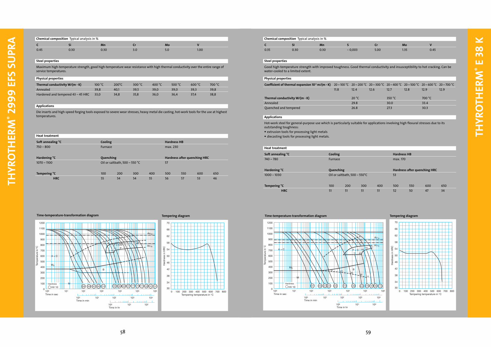
High toughness, good thermal conductivity and insusceptibility to hot cracking, can be water-cooled to a limited extent.
Coefficient of thermal expansion 10-6 m/(m • K) 20 – 100 °C 20 – 200 °C 20 – 300 °C 20 – 400 °C 20 – 500 °C 20 – 600 °C 20 – 700 °C10.9 11.9 12.3 12.7 13.0 13.3 13.5
Thermal conductivity W/(m • K) 20 °C 350 °C 700 °C24.5 26.8 28.8
Mandrels, pressure casting dies, extrusion tools.
Soft annealing °C Cooling Hardness HB750 – 800 Furnace max. 230
Tempering °C 100 200 300 400 500 550 600 650 700HRC 52 50 49 49 50 49 46 36 26
C Si Cr Mo V0.35 0.80 5.0 1.0 0.85
Time-temperature-transformation diagram Tempering diagram
Chemical composition Typical analysis in %
Steel properties
Physical properties
Applications
Heat treatment
Hardening °C Quenching Hardness after quenching HRC1000– 1040 Air, oil or saltbath, 500 – 550 °C 53
36
THYR
OTHE
RM®
2342
EFS
THYR
OTHE
RM®
2343
EFS
/ 23
43 E
FS S
UPRA
37
0
200
600
400
800
1000
1200
1400
1600
1800
2000
200 400 600
Rm
0
20
60
40
80
100
A2
Z
20
Rp0.2
Tens
ile s
tren
gth
Rm
and
0.2
cre
ep li
mit
Rp
0.2
in M
Pa
Test temperature in °C
Are
a re
duc
tion
at fr
actu
re Z
in %
Elo
ngat
ion
at fr
actu
re A
5 in
%
High-temperature strength diagram
Soft annealing °C Cooling Hardness HB750 – 800 Furnace max. 230
Heat treatment
30
34
42
38
46
50
54
58
62
66
70
100 200 300 400 500 6000 700 800
Har
dne
ss in
HR
C
Tempering temperature in °C
1200
1100
1000
900
800
700
600
500
400
300
200
100
0
100 101 102
100 101 102 103 104
100 101 102 103 104 105 106
Ac1e
Ac1b
A + C
MS
M
HV 10
5
B
F + C20 30
5
2
2
10 80 25
6065
95
698 690 681 649 665 642 483 276
665 813
446707
Tem
per
atur
e in
° C
Time in sec
Time in min
Time in hr
Hardness
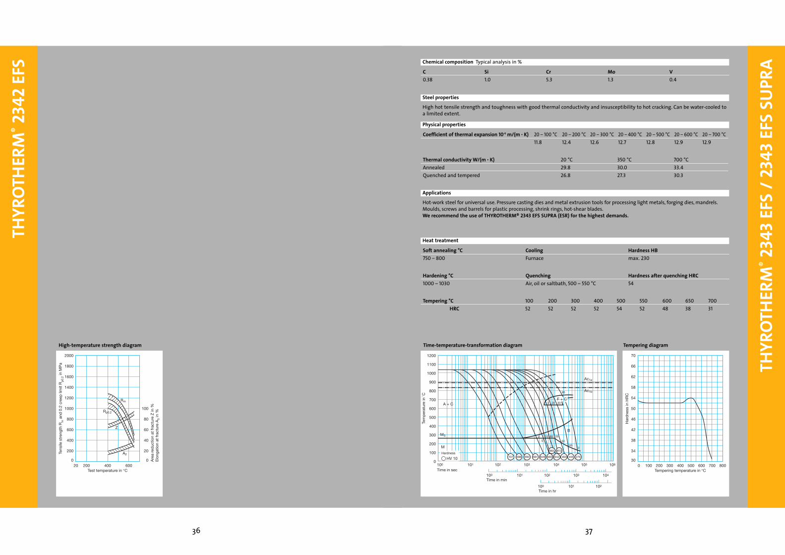
High hot tensile strength and toughness with good thermal conductivity and insusceptibility to hot cracking. Can be water-cooled toa limited extent.
Coefficient of thermal expansion 10-6 m/(m • K) 20 – 100 °C 20 – 200 °C 20 – 300 °C 20 – 400 °C 20 – 500 °C 20 – 600 °C 20 – 700 °C11.8 12.4 12.6 12.7 12.8 12.9 12.9
Thermal conductivity W/(m • K) 20 °C 350 °C 700 °CAnnealed 29.8 30.0 33.4Quenched and tempered 26.8 27.3 30.3
Hot-work steel for universal use. Pressure casting dies and metal extrusion tools for processing light metals, forging dies, mandrels.Moulds, screws and barrels for plastic processing, shrink rings, hot-shear blades.We recommend the use of THYROTHERM® 2343 EFS SUPRA (ESR) for the highest demands.
Tempering °C 100 200 300 400 500 550 600 650 700HRC 52 52 52 52 54 52 48 38 31
C Si Cr Mo V0.38 1.0 5.3 1.3 0.4
Time-temperature-transformation diagram Tempering diagram
Steel properties
Applications
Chemical composition Typical analysis in %
Physical properties
Hardening °C Quenching Hardness after quenching HRC1000 – 1030 Air, oil or saltbath, 500 – 550 °C 54

THYR
OTHE
RM®
2343
EFS
/ 23
43 E
FS S
UPRA
THYR
OTHE
RM®
2344
EFS
/ 23
44 E
FS S
UPRA
39
10
2
6
4
8100
2
4
6
81000
2 4 610 8 100 2 4 6 8 1000100
2 4 6 8 1000 2 4 6 8 10000
500 oC
550 oC
600 oC
500 oC
550 oC
600 oC
Str
ain
in M
Pa
QT strength: 1460 MPa Strain duration in hr
1% creep limit Creep rupture strength
Creep process
0
200
600
400
800
1000
1200
1400
1600
1800
2000
200 400 600
Rp0.2
Rm
0
20
60
40
80
100
Z
20
Tens
ile s
tren
gth
Rm
and
0.2
cre
ep li
mit
Rp
0.2
in M
Pa
Test temperature in °C
Are
a re
duc
tion
at fr
actu
re Z
in %
High-temperature strength diagram
30
34
42
38
46
50
54
58
62
66
70
100 200 300 400 500 6000 700 800
Har
dne
ss in
HR
C
Tempering temperature in °C
1200
1100
1000
900
800
700
600
500
400
300
200
100
0
100 101 102
100 101 102 103 104
100 101 102 103 104 105 106
Ac1e
Ac1b
A + C
MS
M
HV 10
103055
B15
F+C320
100100
707 681 673 657 642 634 572 488
599
219
236
Tem
per
atur
e in
° C
Time in sec
Time in min
Time in hr
Hardness
High hot-wear resistance, high hot tensile strength and toughness. Good thermal conductivity and insusceptibility to hot cracking.Can be water-cooled to a limited extent.
Coefficient of thermal expansion 10-6 m/(m • K) 20 – 100 °C 20 – 200 °C 20 – 300 °C 20 – 400 °C 20 – 500 °C 20 – 600 °C 20 – 700 °C10.9 11.9 12.3 12.7 13.0 13.3 13.5
Thermal conductivity W/(m • K) 20 °C 350 °C 700 °CAnnealed 27.2 30.5 33.4Quenched and tempered 25.5 27.6 30.3
Hot-work steel for universal use. Pressure casting dies and metal extrusion tools for processing light metals, forging dies, mandrels.Moulds, screws and barrels for plastic processing, nitrided ejectors, hot-shear blades.We recommend the use of THYROTHERM® 2344 EFS SUPRA (ESR) for the highest demands.
Soft annealing °C Cooling Hardness HB750 – 800 Furnace max. 230
Tempering °C 100 200 300 400 500 550 600 650 700HRC 53 52 52 54 56 54 50 42 32
C Si Cr Mo V0.40 1.0 5.3 1.4 1.0
Time-temperature-transformation diagram Tempering diagram
Chemical composition Typical analysis in %
Steel properties
Physical properties
Applications
Heat treatment
Hardening °C Quenching Hardness after quenching HRC1010 – 1030 Air, oil or saltbath, 500 – 550 °C 54
38
40
THYR
OTHE
RM®
2344
EFS
/ 23
44 E
FS S
UPRA
THYR
OTHE
RM®
2365
EFS
/ 23
65 E
FS S
UPRA
41
10
2
6
4
8100
2
4
6
81000
2 4 610 8 100 2 4 6 8 1000100
2 4 6 8 1000 2 4 6 8 10000
500 oC
550 oC
600 oC
500 oC
550 oC
600 oC
Str
ain
in M
Pa
QT strength: 1460 MPa Strain duration in hr
1% creep limit Creep rupture strength
Creep process
0
200
600
400
800
1000
1200
1400
1600
1800
2000
200 400 600
Rp0.2
Rm
0
20
60
40
80
100
Z
20
Tens
ile s
tren
gth
Rm
and
0.2
cre
ep li
mit
Rp
0.2
in M
Pa
Test temperature in °C
Are
a re
duc
tion
at fr
actu
re Z
in %
High-temperature strength diagram
Applications
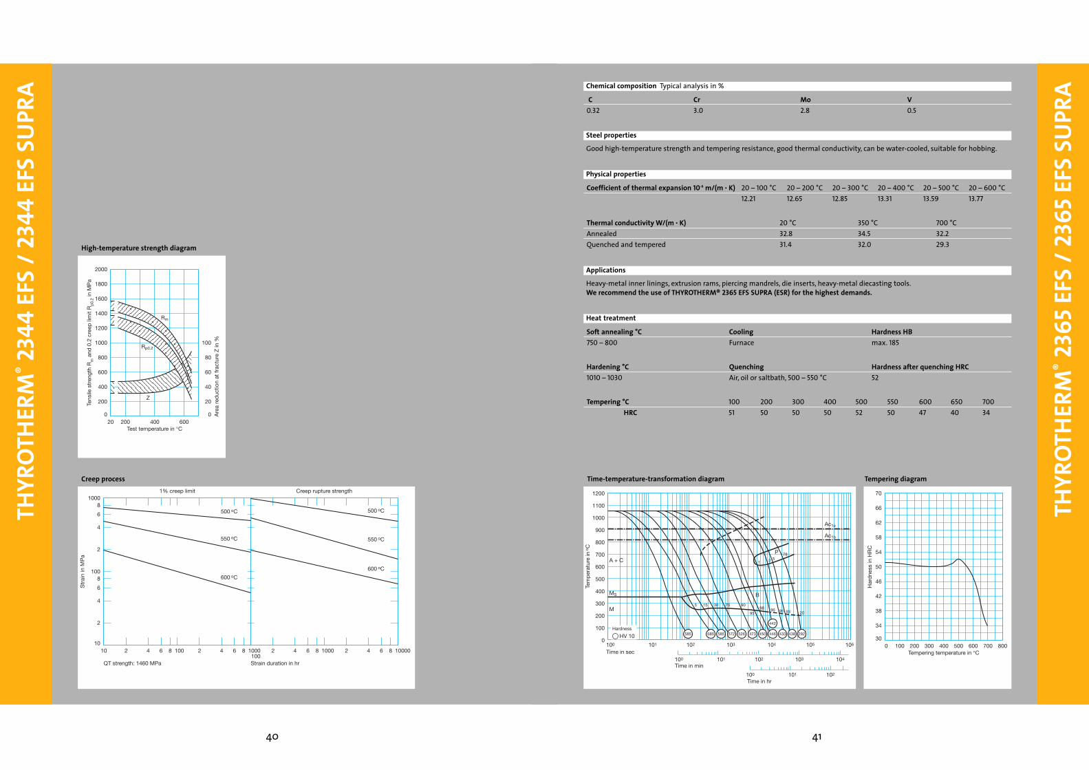
Good high-temperature strength and tempering resistance, good thermal conductivity, can be water-cooled, suitable for hobbing.
Heavy-metal inner linings, extrusion rams, piercing mandrels, die inserts, heavy-metal diecasting tools.We recommend the use of THYROTHERM® 2365 EFS SUPRA (ESR) for the highest demands.
Soft annealing °C Cooling Hardness HB750 – 800 Furnace max. 185
C Cr Mo V0.32 3.0 2.8 0.5
30
34
42
38
46
50
54
58
62
66
70
100 200 300 400 500 6000 700 800
Har
dne
ss in
HR
C
Tempering temperature in °C
1200
1100
1000
900
800
700
600
500
400
300
200
100
0
100 101 102
100 101 102 103 104
100 101 102 103 104 105 106
HV 10
Ac1e
Ac1b
A + C
MS
M
P
B
15
78
3
155 30 75 90
9598 96 95 2093
585 685 585 572 526 473 446450
442
433 438 292
Tem
per
atur
e in
o C
Time in sec
Time in min
Time in hr
Hardness
Hardening °C Quenching Hardness after quenching HRC1010 – 1030 Air, oil or saltbath, 500 – 550 °C 52
Time-temperature-transformation diagram Tempering diagram
Chemical composition Typical analysis in %
Steel properties
Heat treatment
Coefficient of thermal expansion 10-6 m/(m • K) 20 – 100 °C 20 – 200 °C 20 – 300 °C 20 – 400 °C 20 – 500 °C 20 – 600 °C12.21 12.65 12.85 13.31 13.59 13.77
Physical properties
Thermal conductivity W/(m • K) 20 °C 350 °C 700 °CAnnealed 32.8 34.5 32.2Quenched and tempered 31.4 32.0 29.3
Tempering °C 100 200 300 400 500 550 600 650 700HRC 51 50 50 50 52 50 47 40 34

THYR
OTHE
RM®
2365
EFS
/ 23
65 E
FS S
UPRA
42
THYR
OTHE
RM®
2367
EFS
/ 23
67 E
FS S
UPRA
43
10
2
6
4
8100
2
4
6
81000
2 4 610 8 100 2 4 6 8 1000100
2 4 6 8 1000 2 4 6 8 10000
500 oC
550 oC
600 oC
500 oC
550 oC
600 oC
Str
ain
in M
Pa
QT strength: 1460 MPa Strain duration in hr
1% creep limit Creep rupture strength
Creep process
0
200
600
400
800
1000
1200
1400
1600
1800
2000
200 400 600
Rp0.2
Rm
0
20
60
40
80
100
Z
20
Tens
ile s
tren
gth
Rm
and
0.2
cre
ep li
mit
Rp
0.2
in M
Pa
Test temperature in °C
Are
a re
duc
tion
at fr
actu
re Z
in %
High-temperature strength diagram
30
34
42
38
46
50
54
58
62
66
70
100 200 300 400 500 6000 700 800
Har
dne
ss in
HR
C
Tempering temperature in °C
1200
1100
1000
900
800
700
600
500
400
300
200
100
0
100 101 102
100 101 102 103 104
100 101 102 103 104 105 106
HV 10
Ac1e
Ac1b
A + C
MS
M
P5
690 673 665 627 620 634620
606
606 554 548
10515
20 8050
525
85
Tem
per
atur
e in
o C
Time in sec
Time in min
Time in hr
Hardness
Good high-temperature strength and tempering resistance, high hardenability, low tendency to deformation.
Coefficient of thermal expansion 10-6 m/(m • K) 20 – 100 °C 20 – 200 °C 20 – 300 °C 20 – 400 °C 20 – 500 °C 20 – 600 °C 20 – 700 °C11.9 12.5 12.6 12.8 13.1 13.3 13.5
Thermal conductivity W/(m • K) 20 °C 350 °C 700 °CAnnealed 30.8 33.5 35.1Quenched and tempered 29.8 33.9 35.3
Forging dies, diecasting moulds, heavy-metal inner linings, profiling dies and mandrels.We recommend the use of THYROTHERM® 2367 EFS SUPRA (ESR) for the highest demands.
Soft annealing °C Cooling Hardness HB730 – 780 Furnace max. 235
Tempering °C 100 200 300 400 500 550 600 650 700HRC 57 55 53 52 55 55 52 45 36
Kontinuierliches Zeit-Temperatur-Umwandlungsschaubild Anlassschaubild
Chemical composition Typical analysis in %
Steel properties
Physical properties
Applications
Heat treatment
Hardening °C Quenching Hardness after quenching HRC1020 – 1050 Air, oil or saltbath, 500 – 550 °C 57
C Cr Mo V0.37 5.0 3.0 0.6

44
THYR
OTHE
RM®
2367
EFS
/ 23
67 E
FS S
UPRA
THYR
ODUR
®23
79
45
10
2
6
4
8100
2
4
6
81000
2 4 610 8 100 2 4 6 8 1000100
2 4 6 8 1000 2 4 6 8 10000
500 oC
550 oC
600 oC
500 oC
550 oC
600 oC
Str
ain
in M
Pa
QT strength: 1460 MPa Strain duration in hr
1% creep limit Creep rupture strength
Creep process
0
200
600
400
800
1000
1200
1400
1600
1800
2000
200 400 600
Rp0,2
Rm
0
20
60
40
80
100
Z
20
Tens
ile s
tren
gth
Rm
and
0.2
cre
ep li
mit
Rp
0.2
in M
Pa
Test temperature in °C
Are
a re
duc
tion
at fr
actu
re Z
in %
High-temperature strength diagram
Applications
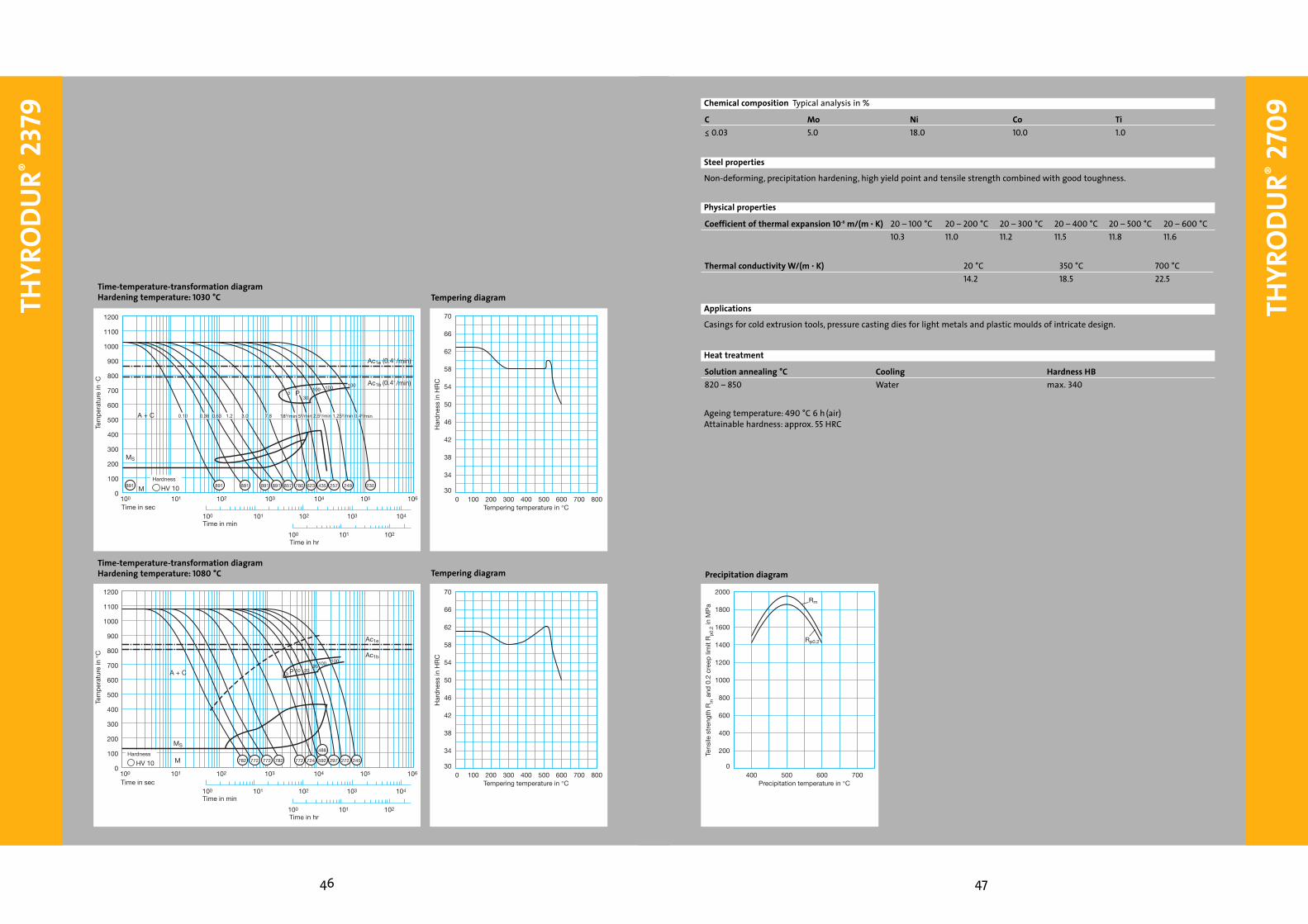
12 % ledeburitic chromium steel, maximum wear resistance, good toughnes, best cutting-edge endurance and tempering resistance,can be nitrided after special heat treatment.
Coefficient of thermal expansion 10-6 m/(m • K) 20 – 100 °C 20 – 200 °C 20 – 300 °C 20 – 400 °C10.5 11.5 11.9 12.2
Thermal conductivity W/(m • K) 20 °C 350 °C 700 °C16.7 20.5 24.2
Deburring tools, thread-rolling rolls and dies, cold extrusion tools, cutting and stamping tools for sheet thicknesses up to 6 mm,precision cutting tools up to 12 mm.Cold pilger mandrels, circular-shear blades, deep-drawing tools, pressure pads and highly wear-resistant plastic moulds.
Soft annealing °C Cooling Hardness HB830 – 860 Furnace max. 250
Hardening °C Quenching Hardness after quenching HRC1000 – 1050 Air, oil or saltbath, 500 – 550 °C 63
Anlassen °C 100 200 300 400 500 525 550 600HRC 63 61 58 58 58 60 56 50
Hardening °C Quenching Hardness after quenching HRC1050 – 1080 Air, oil or saltbath, 500 – 550 °C 61
Tempering °C 100 200 300 400 500 525 550 600(three times) HRC 61 60 58 59 62 62 57 50
C Cr Mo V1.55 12.0 0.7 1.0
Chemical composition Typical analysis in %
Steel properties
Physical properties
Heat treatment
Special heat treatment
46
THYR
ODUR
®23
79
THYR
ODUR
®27
09
47
30
34
42
38
46
50
54
58
62
66
70
100 200 300 400 500 6000 700 800
Har
dne
ss in
HR
C
Tempering temperature in °C
1200
1100
1000
900
800
700
600
500
400
300
200
100
0
100 101 102
100 101 102 103 104
100 101 102 103 104 105 106
Ac1e (0.4° /min)
Ac1b (0.4° /min)
A + C
MS
HV 10
530
100P
M
100 100
891 891 891 891 891 857 780 623 435 257 249 230
0.10 0.36 0.63 1.2 3.0 7.8 180/min 50/min 2.50/min 1.250/min 0.40/min
Tem
per
atur
e in
°C
Time in min
Time in hr
Hardness
Time in sec
Time-temperature-transformation diagramHardening temperature: 1030 °C Tempering diagram
30
34
42
38
46
50
54
58
62
66
70
100 200 300 400 500 6000 700 800
Har
dne
ss in
HR
C
Tempering temperature in °C
1200
1100
1000
900
800
700
600
500
400
300
200
100
0
100 101 102
100 101 102 103 104
100 101 102 103 104 105 106
Ac1e
Ac1b
A + C
MS
MHV 10
103 P 20
95100 100
782 772 772 782 772 724 592 297 272 245
488
Tem
per
atur
e in
°C
Time in min
Time in hr
Hardness
Time in sec
Time-temperature-transformation diagramHardening temperature: 1080 °C Tempering diagram
0
200
600
400
800
1000
1200
1400
1600
1800
2000
400 500 600 700
Rp0.2
Rm
Tens
ile s
tren
gth
Rm
and
0.2
cre
ep li
mit
Rp
0.2
in M
Pa
Precipitation temperature in °C
Non-deforming, precipitation hardening, high yield point and tensile strength combined with good toughness.
Casings for cold extrusion tools, pressure casting dies for light metals and plastic moulds of intricate design.
Ageing temperature: 490 °C 6 h (air)Attainable hardness: approx. 55 HRC
Solution annealing °C Cooling Hardness HB820 – 850 Water max. 340
C Mo Ni Co Ti≤ 0.03 5.0 18.0 10.0 1.0
Coefficient of thermal expansion 10-6 m/(m • K) 20 – 100 °C 20 – 200 °C 20 – 300 °C 20 – 400 °C 20 – 500 °C 20 – 600 °C10.3 11.0 11.2 11.5 11.8 11.6
Precipitation diagram
Thermal conductivity W/(m • K) 20 °C 350 °C 700 °C14.2 18.5 22.5
Chemical composition Typical analysis in %
Steel properties
Physical properties
Applications
Heat treatment

THYR
OTHE
RM®
2714
4948
THYR
OTHE
RM®
2714
Applications
Tough die steel with high tempering resistance and good through hardening. This grade is usually supplied in annealed condition or quenched and tempered to a hardness of 370 to 410 HB (round) or 355 to 400 HB (square, flat).
Standard steel for forging dies of all kinds, mandrels, die holders, armoured trim dies, hot-shear blades.
Soft annealing °C Cooling Hardness HB650 – 700 Furnace max. 250
Hardening °C Quenching Hardness after quenching HRC830 – 870 Oil 58860 – 900 Air 56
Steel properties
Heat treatment
C Cr Mo Ni V0.56 1.1 0.5 1.7 0.1
Chemical composition Typical analysis in %
Coefficient of thermal expansion 10-6 m/(m • K) 20 – 100 °C 20 – 200 °C 20 – 300 °C 20 – 400 °C 20 – 500 °C 20 – 600 °C12.2 13.0 13.3 13.7 14.2 14.4
Thermal conductivity W/(m • K) 20 °C 350 °C 700 °C36.0 38.0 35.0
Physical properties
Tempering °C 100 200 300 400 450 500 550 600 650After quenching in oil – HRC 57 54 52 49 47 46 43 38 34
Tempering °C 100 200 300 400 450 500 550 600 650After quenching in air – HRC 55 52 50 47 45 43 40 36 32
30
34
42
38
46
50
54
58
62
66
70
100 200 300 400 500 6000 700 800
Air
Oil
Har
dne
ss in
HR
C
Tempering temperature in °C
1200
1100
1000
900
800
700
600
500
400
300
200
100
0
100 101 102
100 101 102 103 104
100 101 102 103 104 105 106
HV 10
Ac1e (0.4 K/min)
A + C
MS
M
P15
760 760 758 755 705 450560 410 380 345 270
605 15 888095
240
38
740
Cooling curves for round bar cores with50, 100 and 200 mm dia. on oil hardening
Ac1b (0.4 K/min)
60100
100
B
20 10 5 2.5 1.25 0.8 0.4 0.2 K/min
50 100 200 mm Dmr.
0.34 0.91 1.28 2.2 5.4
RA = 8 8 8 8
8
8 8 12 14 16 7 1
Tem
per
atur
e in
o C
Time in sec
Time in min
Time in hr
Hardness
Time-temperature-transformation diagram Tempering diagram
10
2
6
4
8100
2
4
6
81000
2 4 610 8 100 2 4 6 8 1000100
2 4 6 8 1000 2 4 6 8 10000
500 oC
550 oC
600 oC
500 oC
550 oC
600 oC
Str
ain
in M
Pa
QT strength: 1460 MPa Strain duration in hr
1% creep limit Creep rupture strength
Creep process
0
200
600
400
800
1000
1200
1400
1600
1800
2000
200 400 600
Rp0.2
Rm
0
20
60
40
80
100
Z
20
Tens
ile s
tren
gth
Rm
and
0.2
cre
ep li
mit
Rp
0.2
in M
Pa
Test temperature in °C
Are
a re
duc
tion
at fr
actu
re Z
in %
High-temperature strength diagram

50
THYR
OTHE
RM®
2726
THYR
OPLA
ST®
2738
51
Tough special steel with high insusceptibility to coil breaks.
Special steel for pilger mandrels which are generally delivered in a quenched and tempered condition.
Soft annealing °C Cooling Hardness HB670 – 700 Furnace max. 240
C Cr Mo Ni V0.26 0.75 0.30 1.30 0.20
Chemical composition Typical analysis in %
Heat treatment
Hardening °C Quenching Hardness after quenching HRC840 – 870 Qil 48
Steel properties
Applications
20
24
32
28
36
40
44
48
52
56
60
400 500 600300 700
Har
dne
ss in
HR
C
Tempering temperature in °C
Tempering diagram
Applications
30
34
42
38
46
50
54
58
62
66
70
100 200 300 400 500 6000 700 800
Har
dne
ss in
HR
C
Tempering temperature in °C
1200
1100
1000
900
800
700
600
500
400
300
200
100
0
100 101 102
100 101 102 103 104
100 101 102 103 104 105 106
Ac1e
Ac1b
A + C
MS
M
HV 10 631 572 563 539 440 380 378 306 224
P1 5
4099
B3
10 7094 93 59 1
Tem
per
atur
e in
° C
Time in sec
Time in min
Time in hr
Hardness
Pre-hardened plastic mould steel, hardness in as-delivered condition 280 to 325 HB. Good machinability, suitable for texturing,improved through-hardening in comparison to THYROPLAST® 2711, good polishability.
Thermal conductivity W/(m • K) 20 °C 350 °C 700 °C34.5 33.5 32.0
Large plastic moulds with deep engravings and intensive impacts on the core. THYROPLAST® 2738 is the logical developmentof THYROPLAST® 2311, a pre-hardened plastic mould steel for use in large moulds, which also have to display high core strength. The additional nickel content of 1 % increases the through-hardenability. THYROPLAST® 2738 ia a micro-alloyed, vacuum-degassed steelwith the following excellent features: good machinability, outstanding polishability, good texturing properties.
Soft annealing °C Cooling Hardness HB710 – 740 Furnace max. 235
Tempering °C 100 200 300 400 500 600 700HRC 51 50 48 46 42 39 28
C Mn Cr Ni Mo0.40 1.5 1.9 1.0 0.2
Kontinuierliches Zeit-Temperatur-Umwandlungsschaubild Anlassschaubild
Coefficient of thermal expansion 10-6 m/(m • K) 20 – 100 °C 20 – 200 °C 20 – 300 °C 20 – 400 °C 20 – 500 °C 20 – 600 °C 20 – 700 °C11.1 12.9 13.4 13.8 14.2 14.6 14.9
Chemical composition Typical analysis in %
Steel properties
Physical properties
Heat treatment
Hardening °C Quenching Hardness after quenching HRC840 – 870 Polymer or oil 51

THYR
OTHE
RM®
2740
THYR
OTHE
RM®
2782
SUP
RA
30
34
42
38
46
50
54
58
62
66
70
100 200 300 400 500 6000 700 800
Har
dne
ss in
HR
C
Tempering temperature in °C
Air-hardening special steel for hot working. High toughness and resistance to thermal fatigue.
Special steel for mandrel shafts and pilger mandrels. Pre-machined or fully finished machined mandrels are usually supplied in quenched and tempered condition.
Soft annealing °C Cooling Hardness HB670 – 700 Furnace max. 240
C Cr Mo Ni V0.28 0.70 0.60 2.5 0.30
Chemical composition Typical analysis in %
Steel properties
Applications
Heat treatment
Hardening °C Quenching Hardness after quenching HRC840 – 870 Air or oil 49 Applications
Non-scaling austenitic hot-work steel, oxidizing-resistant with good cold formability. Resistant to scaling in air up to approx. 1150 °C.
Tools for manufacturing of glass products such as blowing iron heads and mandrels, orifices, gathering irons.
C Si Mn Cr Ni0.15 2.0 0.8 25.0 20.0
Chemical composition Typical analysis in %
Steel properties
Physical properties
Heat treatment
Thermal conductivity W/(m • K) 20 °C 500 °C13.0 19.0
Coefficient of thermal expansion 10-6 m/(m • K) 20 – 200 °C 20 – 400 °C 20 – 600 °CAnnealed 16.5 17.0 17.5
Hardening °C Quenching Tensile strength after quenching N/mm2
1000 – 1100 Air or water 495 – 705
5352
Tempering diagram

54
THYR
OTHE
RM®
2787
/ 27
87 S
UPRA
THYR
ODUR
®28
42
55
Applications
Heat treatable, corrosion-resistant, non-scaling hot-work steel..
Tools for glass processing.We recommend the use of THYROTHERM 2787 SUPRA for the highest demands.
Soft annealing °C Cooling Hardness HB710 – 750 Furnace max. 245
Hardening °C Quenching Hardness after quenching HRC990 – 1020 Oil or saltbath, 200 °C 47
Steel properties
Heat treatment
C Si Mn Cr Ni0.22 0.40 0.50 16.5 1.7
Chemical composition Typical analysis in %
Coefficient of thermal expansion 10-6 m/(m • K) 20 – 100 °C 20 – 200 °C 20 – 300 °C 20 – 400 °C 20 – 500 °C 10.0 10.5 11.0 11.0 11.0
Thermal conductivity W/(m • K) 20 °C25
Physical properties
Tempering °C 100 200 300 400 500 600After quenching in oil – HRC 46 45 45 44 43 36
30
34
42
38
46
50
54
58
62
66
70
100 200 300 400 500 6000 700 800
Har
dne
ss in
HR
C
Tempering temperature in °C
Anlassschaubild
Good cutting-edge endurance, dimensionally stable during heat treatment.
Thermal conductivity W/(m • K) 20 °C 350 °C 700 °C33.0 32.0 31.3
Tool steel for universal use, trimming tools, cutting and stamping tools for sheet thicknesses up to 6 mm, thread-cutting tools,reamers, gauges, measuring tools, plastic moulds, shear blades, guide strips.
Soft annealing °C Cooling Hardness HB680 – 720 Furnace max. 220
C Mn Cr V0.90 2.0 0.4 0.1
Coefficient of thermal expansion 10-6 m/(m • K) 20 – 100 °C 20 – 200 °C 20 – 300 °C 20 – 400 °C 20 – 500 °C 20 – 600 °C 20 – 700 °C12.2 13.2 13.8 14.3 14.7 15.0 15.3
Hardening °C Quenching Hardness after quenching HRC790 – 820 Oil or saltbath, 180 – 220 °C 64
30
34
42
38
46
50
54
58
62
66
70
100 200 300 400 500 6000 700 800
Har
dne
ss in
HR
C
Tempering temperature in °C
1200
1100
1000
900
800
700
600
500
400
300
200
100
0
100 101 102
100 101 102 103 104
100 101 102 103 104 105 106
Ac1e (0.4 K/min)
A + C
MS
M
HV 10
23016
P
B
Ac1b (0.4 K/min)
95
100 100 100 100 100
20 4
45
785 780 780 330473
575
293 293 275 257 240RA = 15
0.16 0.4 0.65 1.4 1.6 2.5 6.5 20 K/min 2.5 K/min
5 K/min 1.25 K/min
Tem
per
atur
e in
° C
Time in sec
Time in min
Time in hr
Hardness
Tempering °C 100 200 300 400 500 600HRC 63 60 56 50 42 38
Time-temperature-transformation diagram Tempering diagram
Chemical composition Typical analysis in %
Steel properties
Physical properties
Applications
Heat treatment

56
THYR
OTHE
RM®
2885
EFS
/ 28
85 E
FS S
UPRA
THYR
OTHE
RM®
2885
EFS
/ 28
85 E
FS S
UPRA
57
30
34
42
38
46
50
54
58
62
66
70
100 200 300 400 500 6000 700 800
Har
dne
ss in
HR
C
Tempering temperature in °C
1200
1100
1000
900
800
700
600
500
400
300
200
100
0
100 101 102
100 101 102 103 104
100 101 102 103 104 105 106
HV 10
Ac1e
A + C
MS
M
P
1
760 760 758 755 705 450560
410
380 345 270
97
40
958580
90
240
99
740
Ac1b
3 1075
B
97 90 25
100
100
Tem
per
atur
e in
o C
Time in sec
Time in min
Time in hr
Hardness
Cr-Mo-Co alloyed hot-work steel with high resistance to thermal fatigue and high-temperature strength.
Coefficient of thermal expansion 10-6 m/(m • K) 20 – 100 °C 20 – 200 °C 20 – 300 °C 20 – 400 °C 20 – 500 °C 20 – 600 °C 20 – 700 °C10.5 11.3 11.8 12.3 12.5 12.8 13.0
Diecasting tools, hot-pressing tools, extrusion tools, mainly for heavy metals.
Soft annealing °C Cooling Hardness HB750 – 800 Furnace max. 230
Tempering °C 100 200 300 400 500 550 600 650 700HRC 52 52 50 49 50 51 50 44 31
C Cr Mo V Co0.32 3.0 2.8 0.5 3.0
Time-temperature-transformation diagram Tempering diagram
Chemical composition Typical analysis in %
Steel properties
Physical properties
Applications
Heat treatment
Hardening °C Quenching Hardness after quenching HRC1030 – 1050 Air, oil or saltbath, 500 – 550 °C 54
Thermal conductivity W/(m • K) 20 °C 350 °C 700 °CAnnealed 36.2 38.8 38.2Quenched and tempered 30.3 36.6 34.5
10
2
6
4
8100
2
4
6
81000
2 4 610 8 100 2 4 6 8 1000100
2 4 6 8 1000 2 4 6 8 10000
500 oC
550 oC
600 oC
500 oC
550 oC
600 oC
Str
ain
in M
Pa
QT strength: 1460 MPa Strain duration in hr
1% creep limit Creep rupture strength
Creep process
58
THYR
OTHE
RM®
2999
EFS
SUP
RA
THYR
OTHE
RM®
E 38
K
59
30
34
42
38
46
50
54
58
62
66
70
100 200 300 400 500 6000 700 800
Har
dne
ss in
HR
C
Tempering temperature in °C
Maximum high-temperature strength, good high-temperature wear resistance with high thermal conductivity over the entire range ofservice temperatures.
Die inserts and high-speed forging tools exposed to severe wear stresses, heavy metal die casting, hot-work tools for the use at highesttemperatures.
Soft annealing °C Cooling Hardness HB750 – 800 Furnace max. 230
Tempering °C 100 200 300 400 500 550 600 650HRC 55 54 54 55 56 57 53 46
C Si Mn Cr Mo V0.45 0.30 0.30 3.0 5.0 1.00
Chemical composition Typical analysis in %
Steel properties
Physical properties
Applications
Heat treatment
Hardening °C Quenching Hardness after quenching HRC1070 – 1100 Oil or saltbath, 500 – 550 °C 57
Thermal conductivity W/(m • K) 100 °C 200°C 300 °C 400 °C 500 °C 600 °C 700 °CAnnealed 39,8 40,1 39,5 39,0 39,0 39,3 39,8Hardened and tempered 43 – 45 HRC 33,0 34,8 35,8 36,0 36,4 37,4 38,8
1200
1100
1000
900
800
700
600
500
400
300
200
100
0
100 101 102
100 101 102 103 104
100 101 102 103 104 105 106
HV 10
Ac1e
A + C
MS
M
P30
157
Ac1b
B
F + C
6090 15
85100100100 100 100
161162173176177229300386465518563591594606
Tem
per
atur
e in
o C
Time in sec
Time in min
Time in hr
Hardness
Time-temperature-transformation diagram
Hot-work steel for general-purpose use which is particularly suitable for applications involving high flexural stresses due to its outstanding toughness:• extrusion tools for processing light metals• diecasting tools for processing light metals.
Soft annealing °C Cooling Hardness HB740 – 780 Furnace max. 170
C SI Mn S Cr Mo V0.35 0.30 0.30 < 0,003 5.00 1.35 0.45
Coefficient of thermal expansion 10-6 m/(m • K) 20 – 100 °C 20 – 200 °C 20 – 300 °C 20 – 400 °C 20 – 500 °C 20 – 600 °C 20 – 700 °C11.8 12.4 12.6 12.7 12.8 12.9 12.9
Hardening °C Quenching Hardness after quenching HRC1000 – 1030 Oil or saltbath, 500 – 550°C 53
30
34
42
38
46
50
54
58
62
66
70
100 200 300 400 500 6000 700 800
Har
dne
ss in
HR
C
Tempering temperature in °C
1200
1100
1000
900
800
700
600
500
400
300
200
100
0
100 101 102
100 101 102 103 104
100 101 102 103 104 105 106
Ac1e
Ac1b
A + C
MS
HV 10
3
10
10
B
M
657 633 620 620 572 483 270 197 183
Time in min
Time in hr
Hardness
F + C85
100100 100
175433627
3585
8010
Time in sec
Tem
per
atur
e in
° C
Time-temperature-transformation diagram Tempering diagram
Chemical composition Typical analysis in %
Steel properties
Physical properties
Applications
Heat treatment
Good high-temperature strength with improved toughness. Good thermal conductivity and insusceptibility to hot cracking. Can bewater-cooled to a limited extent.
Thermal conductivity W/(m • K) 20 °C 350 °C 700 °CAnnealed 29.8 30.0 33.4Quenched and tempered 26.8 27.3 30.3
Tempering °C 100 200 300 400 500 550 600 650HRC 51 51 51 51 52 50 47 34
Tempering diagram

occur between the surface andthe core cause stresses resultingin dimensional changes. Thetemperature differencesdepend on the size and shapeof the mould. The designershould ensure that the mould is of symmetrical shape. As the temperature differencesincrease at larger volumes, itmust be checked whether it isexpedient to divide the mouldinto individual segments.This design also offers theadvantage that worn or damaged individual parts canbe replaced more quickly. Thinwebs within the mould are afrequent cause of problemsduring heat treatment. As thesethin webs cool more quickly, theaustenite is converted into martensite more quickly therethan in larger cross-sections. Insuch cases, it should always bechecked whether it is possibleto divide the mould.
Machining
Tools made of hot-work toolsteel are manufactured bymetal-cutting and non-cuttingshaping processes. Duringmetal-cutting, surface tensionsare generated and the tensionof the workpiece is changed,depending on the depth ofmachining. In the event ofextensive metal-cutting, it isrecommendable to performthermal relief for annealed andquenched and tempered partsbefore finish-machining, inorder to reduce the risk ofdistortion or stress crackingduring finish-machining.Critical machining processes are processes in which the
Design
The design is very important forthe economical use of tools. Aprecisely machined tool whichhas undergone the correct heattreatment and is made of thebest possible tool steel will stillbreak after a short time, if it isof faulty design. The rightdesign and proper heattreatment are essentialprerequisites for avoiding highburdens in terms of time andmoney. The following factorscan promote susceptibility tocracking or breaking:
• incorrect dimensioning• abrupt cross-section
transitions• sharp notches
(e.g. tool marks and grinding marks, scriber marks, punched numbers, etc.)
As the strength of the mouldsincreases, so does their suscep-tibility to notches: the higherthe hardness selected, the more carefully thesurfaces have to be machinedand the cross-section transiti-ons produced. The radii shouldthus be designed as largeas possible and should also bepolished, if possible. In general,the reduced toughness at highhardness levels, as well as thedifferent toughness propertiesof the various grades, must betaken into consideration.
Design andheat treatmentThe microstructural transformations occurringduring heat treatmentand the temperature differences which inevitably
GrindingPerfect grinding of the hardenedtools is particularly important.When selecting the grindingwheel, it must be ensured thatthe particle size, hardness andbond are adapted to the steelto be ground. The harder thesteel, the softer the wheel andthe lower the contact pressuremust be. Despite adequatewater cooling, selection of the wrong grinding wheel or excessive contact pressurecauses local over-heating,resulting in soft skin and grinding cracks. Annealingcolours or "burnt" areas mustnot occur. The following fundamentally applies togrinding:
• use the correct grinding wheel
• apply suitable contactpressure (the higher thehardness, the lower thecontact pressure)
• use open grinding wheels• provide a generous,
wellcontrolled coolant supply
PolishingPolishing is often the lastmachining step when manufacturing a mould. Thequality of the polished surfaceis the decisive criterion for producing samples of themould. Early minimisation ofthe risk is correspondinglyimportant.The polishing result is decisivelydetermined by:
• steel quality• heat treatment condition• polishing method
Steel qualityIn addition to the analyticalcomposition, the manufacturingprocess also has a decisiveimpact on polishability. Forexample, the polishing resultcan be affected by non-metallicinclusions (purity) or hard structural components, such as primary carbides, which canstipple the polished surface.In order to improve the purity,all hot-work tool steels fromEdelstahl Witten-Krefeld andEdelstahlwerke Südwestfalenundergo secondary metallurgicaltreatment in ladle furnaces and vacuum-degassing plants.The electroslag remelted (ESR) or vacuum arc remelted(VAR) versions offer further refinement – e.g.THYROTHERM® 2343/44 EFSSUPRA or THYROPLAST® 2083SUPRA.
Heat treatment conditionIt is fundamentally true thatthe harder the mould, the betterit can be polished. Hardnesses > 50 HRC are recommendablefor mirror-finish polishes. Thereis a risk of rippling (so-calledorange peel) in the eventof low or uneven hardness.
Polishing methodIn addition to the selection ofthe right steel and the heattreatment, the polishingmethod is extremely important.The polishing result largelydepends on the experienceand skill of the polisher. Thefiner the graduation of the grinding and polishing operations,the better the surface quality.
MillingOur tool steels can be cut wellin accordance with their intendedapplication. Machining withmodern metal-cutting tools (carbide cutting tools) is advisable for economicalreasons. The setting of themetal-cutting parameters (cutting speed and feed rate)pursuant to the followingtable and the tool manufacturer’sinstructions is a decisivefactor for success. Milling usingcarbide cutting tools is to beperformed “dry” (withoutlubricoolant). If increased wearoccurs on the reversible tipduring milling, the nature ofthe wear must be examined.Based on the result of thisexamination, the cuttingspeed and the feed rate mayhave to be checked and reset.Experience shows that theseare often set too low at thestart. The size of cutting depthap is of little significance interms of wear when setting thefeed rate and cutting speed.Stable machine and clampingconditions are always to beaimed for.
• always use reversible carbidecutting tips withoutlubricoolants
• rough-machine at an angle of 0° and with negative chamfer
• set the cutting speed at thehigh end of the range
• when using HSS tools, thelubricoolants must bemixed in the upper range,according to the manufacturer’s instructions
Notes on processing
60 61
structure of the steel is changedby thermal influences.Electrical discharge machiningIn this process, the surface iseroded by a spark dischargebetween an electrode and thetool to be manufactured.Electrical discharge machiningprimarily offers advantageswhen machining hardenedtools. The extreme temperaturesin the working gap (approx.10,000 °C) cause the erodedmaterial to evaporate beforebeing carried off by the dielectric.A melted zone is left, with heateffects reaching deep into thematerial. Fine incipient cracksform here, which can result inthe premature failure of amould. The impulse energy andthe washing by the dielectricdetermine the depth of thisbrittle zone of new hardeningand the magnitude of the stresses. Only careful mechanicalreworking (removal of thedamaged edge zones) ensuressufficient protection againstprogression of the cracks.Washing from all sides must beensured during structural erosion,in order to avoid orientation ofthe structure in the direction ofwashing.
THYROTHERM® 2343 EFS mould insert
Failure due to faulty electrical discharge machining

62 63
Grade Treatmentcondition
HSS tool THYRAPID® 3207 THYRAPID® 3207
Carbide cutting toolCoated with P 25/P25 TILIAN P 10/P15
Rough-machining Finish-mashining Rough-machining Finish-mashiningCuttingspeed
Vc (m/min)
Feed rate
s = mm/rev.
Cuttingspeed
Vc (m/min)
Feed rate
s = mm/rev.
Cuttingspeed
Vc (m/min)
Feed rate
s = mm/rev.
Cuttingspeed
Vc (m/min)
Feed rate
s = mm/rev.THYRODUR® 1730 Annealed 20 – 40 0.2 – 0.4 40 – 70 0.1 – 0.2 150 – 230 0.4 – 1.0 300 – 420 0.1 – 0.4THYROPLAST® 2083 Annealed 15 – 25 0.2 – 0.4 25 – 50 0.1 – 0.2 125 – 195 0.4 – 1.0 250 – 370 0.1 – 0.4THYROPLAST® 2312 QT 15 – 30 0.2 – 0.4 35 – 60 0.1 – 0.2 130 – 200 0.4 – 1.0 270 – 390 0.1 – 0.4THYROTHERM® 2329 QT 10 – 20 0.2 – 0.4 20 – 30 0.1 – 0.2 115 – 175 0.4 – 1.0 235 – 350 0.1 – 0.4THYROTHERM® 2342 Annealed 15 – 25 0.2 – 0.4 25 – 50 0.1 – 0.2 125 – 195 0.4 – 1.0 250 – 370 0.1 – 0.4THYROTHERM® 2343 Annealed 15 – 25 0.2 – 0.4 25 – 50 0.1 – 0.2 125 – 195 0.4 – 1.0 250 – 370 0.1 – 0.4THYROTHERM® 2344 Annealed 15 – 25 0.2 – 0.4 25 – 50 0.1 – 0.2 125 – 195 0.4 – 1.0 250 – 370 0.1 – 0.4THYROTHERM® 2365 Annealed 15 – 25 0.2 – 0,4 25 – 50 0.1 – 0.2 125 – 195 0.4 – 1.0 250 – 370 0.1 – 0.4THYROTHERM® 2367 Annealed 15 – 25 0.2 – 0.4 25 – 50 0.1 – 0.2 125 – 195 0.4 – 1.0 250 – 370 0.1 – 0.4THYRODUR® 2379 Annealed 10 – 20 0.2 – 0.4 20 – 30 0.1 – 0.2 115 – 175 0.4 – 1.0 235 – 350 0.1 – 0.4THYRODUR® 2709 Sol.-annealed 15 – 25 0.2 – 0.4 25 – 50 0.1 – 0.2 125 – 195 0.4 – 1.0 250 – 370 0.1 – 0.4THYROTHERM® 2714 QT 10 – 20 0.2 – 0.4 20 – 30 0.1 – 0.2 115 – 175 0.4 – 1.0 235 – 350 0.1 – 0.4THYROTHERM® 2726 Annealed 15 – 30 0.2 – 0.4 35 – 60 0.1 – 0.2 130 – 200 0.4 – 1.0 270 – 390 0.1 – 0.4THYROTPLAST® 2738 QT 10 – 20 0.2 – 0.4 20 – 30 0.1 – 0.2 125 – 175 0.4 – 1.0 235 – 350 0.1 – 0.4THYROTHERM® 2740 Annealed 15 – 25 0.2 – 0.4 25 – 50 0.1 – 0.2 125 – 195 0.4 – 1.0 250 – 370 0.1 – 0.4THYROTHERM® 2782 Sol.-annealed 15 – 25 0.2 – 0.4 25 – 50 0.1 – 0.2 125 – 195 0.4 – 1.0 250 – 370 0.1 – 0.4THYROTHERM® 2787 QT 10 – 20 0.2 – 0.4 20 – 30 0.1 – 0.2 115 – 175 0.4 – 1.0 235 – 350 0.1 – 0.4THYRODUR® 2842 Annealed 15 – 30 0.2 – 0.4 35 – 60 0.1 – 0.2 130 – 200 0.4 – 1.0 270 – 390 0.1 – 0.4THYROTHERM® 2885 Annealed 15 – 25 0.2 – 0.4 25 – 50 0.1 – 0.2 125 – 195 0.4 – 1.0 250 – 370 0.1 – 0.4THYROTHERM® 2999 Annealed 10 – 20 0.2 – 0.4 20 – 30 0.1 – 0.2 115 – 175 0.4 – 1.0 235 – 350 0.1 – 0.4THYROTHERM® E 38 K Annealed 15 – 25 0.2 – 0.4 25 – 50 0.1 – 0.2 125 – 195 0.4 – 1.0 250 – 370 0.1 – 0.4
Grade Treatmentcondition
HSS tool THYRAPID® 3207 THYRAPID® 3207
Carbide cutting toolCoated with P 40 TILIAN P 25
Rough-machining Finish-mashining Rough-machining Finish-mashiningCuttingspeed
Vc (m/min)
Feed rate
fz (mm)
Cuttingspeed
Vc (m/min)
Feed rate
fz (mm)
Cuttingspeed
Vc (m/min)
Feed rate
fz (mm)
Cuttingspeed
Vc (m/min)
Feed rate
fz (mm)THYRODUR® 1730 Annealed 15 – 25 0.10 – 0.20 20 – 40 0.05 – 0.10 150 – 210 0.30 – 0.60 120– 200 0.10 – 0.20THYROPLAST® 2083 Annealed 10 – 18 0.10 – 0.20 15 – 30 0.05 – 0.10 110 – 170 0.30 – 0.60 110 – 170 0.10 – 0.20THYROPLAST® 2312 QT 12 – 20 0.10 – 0.20 20 – 35 0.05 – 0.10 140 – 190 0.30 – 0.60 120 – 180 0.10 – 0.20THYROTHERM® 2329 QT 8 – 10 0.18 – 0.25 10 – 15 0.20 – 0.40 80 – 160 0.20 – 0.40 90 – 180 0.15 – 0.25THYROTHERM® 2342 Annealed 10 – 18 0.20 – 0.40 15 – 25 0.30 – 0.60 100 – 160 0.20 – 0.40 110 – 190 0.15 – 0.25THYROTHERM® 2343 Annealed 10 – 18 0.10 – 0.20 15 – 30 0.05 – 0.10 110 – 170 0.30 – 0.60 110 – 170 0.10 – 0.20THYROTHERM® 2344 Annealed 10 – 18 0.10 – 0.20 15 – 30 0.05 – 0.10 110 – 170 0.30 – 0.60 110 – 170 0.10 – 0.20THYROTHERM® 2365 Annealed 10 – 18 0.10 – 0.20 15 – 30 0.05 – 0.10 110 – 170 0.30 – 0.60 110 – 170 0.10 – 0.20THYROTHERM® 2367 Annealed 10 – 18 0.10 – 0.20 15 – 30 0.05 – 0.10 110 – 170 0.30 – 0.60 110 – 170 0.10 – 0.20THYRODUR® 2379 Annealed 8 – 15 0.10 – 0.20 12 – 20 0.05 – 0.10 90 – 160 0.30 – 0.60 100 – 160 0.10 – 0.20THYRODUR® 2709 Sol.-annealed 10 – 18 0.20 – 0.40 15 – 25 0.30 – 0.60 100 – 160 0.20 – 0.40 110 – 190 0.15 – 0.25THYROTHERM® 2714 QT 8 – 10 0.18 – 0.25 10 – 15 0.20 – 0.40 80 – 160 0.20 – 0.40 90 – 180 0.15 – 0.25THYROTHERM® 2726 Annealed 12 – 20 0.20 – 0.50 18 – 30 0.30 – 0.70 120 – 180 0.20 – 0.40 130 – 210 0.15 – 0.25THYROPLAST® 2738 QT 8 – 15 0.10 – 0.20 12 – 20 0.05 – 0.10 90 – 160 0.30 – 0.60 100 – 160 0.10 – 0.20THYROTHERM® 2740 Annealed 10 – 18 0.20 – 0.40 15 – 25 0.30 – 0.60 100 – 160 0.20 – 0.40 110 – 190 0.15 – 0.25THYROTHERM® 2782 Sol.-annealed 10 – 18 0.20 – 0.40 15 – 25 0.30 – 0.60 100– 160 0.20 – 0.40 110 – 190 0.15 – 0.25THYROTHERM® 2787 QT 8 – 10 0.18 – 0.25 10 – 15 0.20 – 0.40 80 – 160 0.20 – 0.40 90 – 180 0.15 – 0.25THYRODUR® 2842 Annealed 12 – 20 0.10 – 0.20 20 – 35 0.05 – 0.10 140 – 190 0.30 – 0.60 120 – 180 0.10 – 0.20THYROTHERM® 2885 Annealed 10 – 18 0.10 – 0.20 15 – 30 0.05 – 0.10 110 – 170 0.30 – 0.60 110 – 170 0.10 – 0.20THYROTHERM® 2999 Annealed 8 – 10 0.18 – 0.25 10 – 15 0.20 – 0.40 80 – 160 0.20 – 0.40 90 – 180 0.15 – 0.25THYROTHERM® E 38 K Annealed 10 – 18 0.10 – 0.20 15 – 30 0.05 – 0.10 110 – 170 0.30 – 0.60 110 – 170 0.10 – 0.20
Machining values for turning tools using HSS and carbide cutting tools
Grade Treatmentcondition
Cutting speedV = m/min
Feed rateS = mm/rev.
Drill diametermm
3343, 3243 3343, 3243+ TiN
HM K 10 3343, 3243 3343, 3243+ TiN
HM K 10 3343, 3243 3343, 3243+ TiN
HM K 10
THYRODUR® 1730 Annealed 14 – 20 25 – 30 60 – 100 0.04 – 0.20 0.16 – 0.25 0.06 – 0.30 8 – 16 8 – 16 20 – 47THYROPLAST® 2083 Annealed 8 – 14 18 – 23 40 – 60 0.04 – 0.14 0.12 – 0.20 0.06 – 0.20 8 – 16 8 – 16 20 – 47THYROPLAST® 2312 QT 10 – 16 20 – 25 50 – 80 0.04 – 0.20 0.16 – 0.25 0.06 – 0.30 8 – 16 8 – 16 20 – 47THYROTHERM® 2329 QT 6 – 10 15 – 20 30 – 50 0.04 – 0.16 0.12 – 0.20 0.06 – 0.20 8 – 16 8 – 16 20 – 47THYROTHERM® 2342 Annealed 8 – 14 18 – 23 40 – 60 0.04 – 0.14 0.12 – 0.20 0.06 – 0.20 8 – 16 8 – 16 20 – 47THYROTHERM® 2343 Annealed 8 – 14 18 – 23 40 – 60 0.04 – 0.14 0.12 – 0.20 0.06 – 0.20 8 – 16 8 – 16 20 – 47THYROTHERM® 2344 Annealed 8 – 14 18 – 23 40 – 60 0.04 – 0.14 0.12 – 0.20 0.06 – 0.20 8 – 16 8 – 16 20 – 47THYROTHERM® 2365 Annealed 8 – 14 18 – 23 40 – 60 0.04 – 0.14 0.12 – 0.20 0.06 – 0.20 8 – 16 8 – 16 20 – 47THYROTHERM® 2367 Annealed 8 – 14 18 – 23 40 – 60 0.04 – 0.14 0.12 – 0.20 0.06 – 0.20 8 – 16 8 – 16 20 – 47THYRODUR® 2379 Annealed 6 – 10 15 – 20 30 – 50 0.04 – 0.16 0.12 – 0.20 0.06 – 0.20 8 – 16 8 – 16 20 – 47THYRODUR® 2709 Sol.-annealed 8 – 14 18 – 23 40 – 60 0.04 – 0.14 0.12 – 0.20 0.06 – 0.20 8 – 16 8 – 16 20 – 47THYROTHERM® 2714 QT 6 – 10 15 – 20 30 – 50 0.04 – 0.16 0.12 – 0.20 0.06 – 0.20 8 – 16 8 – 16 20 – 47THYROTHERM® 2726 Annealed 10 – 18 20 – 25 50 – 80 0.04 – 0.20 0.16 – 0.25 0.06 – 0.30 8 – 16 8 – 16 20 – 47THYROTPLAST® 2738 QT 6 – 10 15 – 20 30 – 50 0.04 – 0.16 0.12 – 0.20 0.06 – 0.20 8 – 16 8 – 16 20 – 47THYROTHERM® 2740 Annealed 8 – 14 18 – 23 40 – 60 0.04 – 0.14 0.12 – 0.20 0.06 – 0.20 8 – 16 8 – 16 20 – 47THYROTHERM® 2782 Sol.-annealed 8 – 14 18 – 23 40 – 60 0.04 – 0.14 0.12 – 0.20 0.06 – 0.20 8 – 16 8 – 16 20 – 47THYROTHERM® 2787 QT 6 – 10 15 – 20 30 – 50 0.04 – 0.16 0.12 – 0.20 0.06 – 0.20 8 – 16 8 – 16 20 – 47THYRODUR® 2842 Annealed 10 – 18 20 – 25 50 – 80 0.04 – 0.20 0.16 – 0.25 0.06 – 0.30 8 – 16 8 – 16 20 – 47THYROTHERM® 2885 Annealed 8 – 14 18 – 23 40 – 60 0.04 – 0.14 0.12 – 0.20 0.06 – 0.20 8 – 16 8 – 16 20 – 47THYROTHERM® 2999 Annealed 8 – 14 18 – 23 40 – 60 0.04 – 0.14 0.12 – 0.20 0.06 – 0.20 8 – 16 8 – 16 20 – 47THYROTHERM® E 38 K Annealed 8 – 14 18 – 23 40 – 60 0.04 – 0.14 0.12 – 0.20 0.06 – 0.20 8 – 16 8 – 16 20 – 47
Machining values for drilling tool steels
Machining values for milling tools using HSS and carbide cutting tools
Notes on processing

joined together. In order toreduce shrinkage stress, the welding bead should be hammered
• cool the tools to approx.80 to 100 °C after the welding process
• heat to annealing temperatureimmediately afterwards and soft anneal (annealed tools) or heat to approx. 50 °C below the original temperingtemperature and temper (quenched and tempered steel grades).
Heat treatmentThe potential of the tool steelused is only fully exploited bymeans of heat treatment adaptedto the steel composition, theintended use and the component size. Incorrect heattreatment can impair the functionality and propertiesof the tool. Despite achievingthe required hardness, thetoughness can be considerablyreduced by a coarse hardeningmicrostructure, for example.Heat treatment processes havebeen developed further andundergone extensive fine-tuning on the basis of detailedresearch and practical studies.The furnace units used for heat
performed on heat-treatedsteels and the temperaturehere must be approx. 50 °Cbelow the last temperingtemperature, in order to avoida drop in hardness.
HardeningHeatingOwing to the low thermal conductivity and the differenttool cross-sections, considerablethermal stresses occur in theevent of rapid heating to hardening temperature.These can result in thedeformation or even cracking of tools. In this context, certainpre-heating stages must beobserved, these being listed inthe time-temperaturesequences in the material datasheets. The holding time at thetemperature is 30 seconds permm wall thickness at both thefirst and second pre-heatingstages. For high-alloy tool steelswith a hardening temperatureof more than about 900 °C,the third pre-heating stage ataround 850 °C also serves todissolve part of the carbides, aswell as being important for thereasons already mentionedabove. The holding time atthis temperature is thus oneminute per mm wall thickness –double that at the second pre-heating stage.
AustenitizingThe tools are brought up to thehardening temperature listed inthe material data sheets afterthe last pre-heating stage.After being thoroughly heated(temperature equalization),they must be held at this temperature to ensurecomplete transformation. The
64 65
Repair welding
Owing to their alloy structure,tool steels are among the steelswhere welding involves a certainrisk. While the weld seam cools,thermal and microstructuraltransformation stresses occur,which can result in cracking.However, design changes,natural wear or tool failure dueto breakage or cracking oftenmean that repair by means ofan electric welding process isinevitable. The following basicrules should be followed duringrepair welding:
• clean surfaces thoroughly,grind out cracks in U-shaped fashion
• thorough pre-heating,pre-heating temperature above martensite formation temperature (see time-temperature-transformation diagram in the material data sheet for Ms line) in order to avoid microstructuraltransformations during welding
• high-alloy steels: heat to hardening temperature (austenitizing), cool to abovemartensite start temperature
• weld (with intermediate heating if necessary)
• use electrodes correspondingto the base material
• the TIG welding method has the advantage of a finer microstructure, as it involves less heating and a higher cooling rate than coveredwelding electrodes
• in order to minimize deformation, relatively largeareas should be welded in fields during deposition and these fields subsequently
treatment today are primarilyinert gas, chamber, fluidised-bed and vacuum furnaces.Despite their high flexibility,salt-bath systems are no longervery significant due to stricterenvironmental protectionregulations. The material datasheets contain time-temperature-transformation diagrams (TTTdiagrams) for continuouscooling, in order to improveunderstanding of the transformation processes occurring during hardening.
Stress-relief annealingMachining stresses occurduring metal-cutting and non-cutting shaping. These canresult in deformation and possiblyin expensive reworking in thecourse of subsequent heattreatment. Stress-relief annealingshould be performed at a temperature of 600 to 650 °Cafter initial machining,particularly for tools of complexgeometry. The holding time atthis temperature should be atleast two hours, or at least onehour per 50 mm wall thicknessfor larger tools. The tool mustthen be slowly cooled in thefurnace. This stress-reliefannealing should also be
diagram gives reference data for selection of the time after reaching the hardeningtemperature on the tool surfaceas a function of the wall thickness. The immersion timesin the salt bath can also bedetermined using the diagram.
QuenchingQuenching the tools is the most critical phase of the heattreatment process. There is arisk of heat treatment cracksdue to the coinciding of thermal and microstructuraltransformation stress. Design-related factors promotingcracking are abrupt materialtransitions, different wallthicknesses (webs) and largehardening cross-sections.From the point of view of thematerial, cooling should beas quick as possible, in order to achieve purely martensitictransformation. However,as regards the risk of heattreatment cracking described,compromises must be madeand agreed on by the steelmanufacturer, heat treatment
SystemProperties
Saltbath Chamberfurnace
Fluidisedbed furnace
Inert-gasfurnace
Vacuum-furnace
Heat transfer +++ ++ +++ ++ +Flexibility +++ ++ +++ ++ +Deformation problems ++ +++ ++ + +Surface treatment + + + + oPartial hardening/tempering
+ + o o o
Environmental pollution +++ + ++ ++ +Avoidance of undesirable surface effects
++ o ++ ++ +++
Cleaning of tools o o + ++ +++
Notes on processing
Advantages and disadvantages of various heat treatment systems
company and toolmaker in eachindividual case. The quenching medium for every grade is givenin the material data sheets. Inhot-bath hardening, theworkpieces remain in the hotbath until the temperature isequalised and are then cooledfurther in air. Owing to the riskof stress cracking, quenching toroom temperature shouldalways be avoided. The tools are expediently cooled to around80 °C and immediately transferred to an equalizationfurnace, possibly after hotwashing.
a
a
a
a = Wall thickness aTim
e in
min
Wall thickness in mm (hardening cross-section)
High-alloy steels (ledeburitic, 12 % chromium steels) Carbon, low and medium-alloy tool steels
020 40 60 80 100 120 140 160 180 200 220 240 260 280
200
180
160
140
120
100
80
60
40
20
Reference values for the holding time at hardening temperature
Sharp-edged transitions

Plasma nitridingPlasma nitriding is a thermo-chemical process. Treatment iscarried out in vacuum plants,into which treatment gasescontaining nitrogen are fed. Aplasma state is built up by anelectrical field. The electricallycharged nitrogen ions generatedin this context are acceleratedtowards the workpiece and candiffuse into the surface. The treatment temperature rangefor this process is between 400and 600 °C.
66 67
EqualizationOnce the tools have beenquenched to 80 °C, they aretransferred directly to a furnacewith a temperature of 100 to150 °C. In particular, relativelylarge tools are held at this temperature in order to equalizethe temperature across the entire cross-section and achieveoptimum transformation in thecore as well.
TemperingTempering is necessary in orderto achieve an appropriatehardness and toughness for therespective service requirement.Tempering must be performedimmediately after quenchingand equalization in order toavoid heat treatment cracks.The tools are slowly heated to the prescribed temperingtemperature. This can be takenfrom the tempering diagram ofthe relevant material data sheetand is governed by the desired working hardness. The holdingtime at tempering temperatureis 1 hour per 20 mm wall thickness, or at least two hours.The tools are then cooled in airand their hardness is tested.
Gas nitridingGas nitriding is performed at480 to 540 °C. The necessarynitriding time for tools in thisprocess is 15 to 30 hours. By partially covering areas with a coating of copper, nickel orpastes, these areas can beexcluded from the nitridingtreatment, thus achieving partial nitriding.
Bath nitridingThe following points must beobserved in bath nitriding orTenifer treatment: the toolsmust first be pre-heated to atemperature of 400 °C. Bathnitriding is performed at a temperature of 520 to 570 °C.The holding time is governed bythe desired depth of nitridingand is generally two hours.
Notes on processing
Overheated during hardening, different cross-sections
Pre-maching
Finish-maching
600 – 650 °C
3rd pre-heating stage**1 min/mm ��900 °C
2nd pre-heatingstage 30s/mm��650 °C
Stress-reliefannealing
Heating – Austenitizing – Quenching Tempering
Air Air Air
��100 °C
1st pre-heating stage30 s/mm ��400 °C
Hot bath*
Air/Oil
1st 2nd Furthertempering* tempering* tempering*
Hardening temperature*
Equalizationtemperature1h/100 mm
* Temperatures according to material data sheets
Slowfurnancecooling
** Steels with austenitizing temperature > 900 °C
Time-temperature sequence diagram for the heat treatment of hot-work tool steels
Heat treatment
Time
Tem
pera
ture
Surface treatment
ProcessesThe properties of the surfacezones of tool steels can bechanged, and the tool servicelives thus extended, with thehelp of surface treatmentprocesses. The processes can bebroken down into coating anddiffusion processes.
NitridingNitriding has become the mostimportant of all known surfacetreatment processes for tools.Before nitriding, the tools mustbe heat-treated and temperedto a temperature above the subsequent nitriding temperature. Steel grades whichare supplied in quenched-and-tempered condition must bestress-relief annealed at600 to 650 °C after initialmachining in order to avoiddeformation during subsequentnitriding. Owing to the thinnessof the nitrided layer, the toolscannot usually be reground. Thetools must be cleaned anddegreased before nitriding.Nitriding can be performed in asalt bath, gas or plasma. Layerthicknesses of up to 0.5 mm areachieved. The hardness of nitrided surfaces is up to 1100HV (approx. 70 HRC), dependingon the steel composition.
Process Treatment temperature in °C
Required propertiesof the tool steels orprerequisites
Layer thickness Surface hardness in HV
Nitriding 470 – 570 tempering resistance,hardened or QT condi-tion,de-passivated surface
up to 0.5 mm max. 1100
Boriding 800 – 1050 insensitivity to overheating, minimumpossible Si content
up to 0.4 mm max. 2000
Oxidizing
Spark deposition
300 – 550
several 1000
tempering resistance,degreased surfaces
none
up to 0.01 mm
up to 0.1 mm
–
approx. 950Titanium carbidecoating (CVD)
> 900 insensitivity to overheating, bright,metallic surface
6 – 9 μm max. 4800
Titanium carbidecoating (PVD)Hard nickel plating
approx. 500 tempering resistance,high basic hardness
2 – 5 μm 2000 – 2500
Hard chromiumplating
50 – 70 minimum possible C content, de-passivatedsurface, heat treatmentin neutral environment
up to 1 mm 1000 – 1200
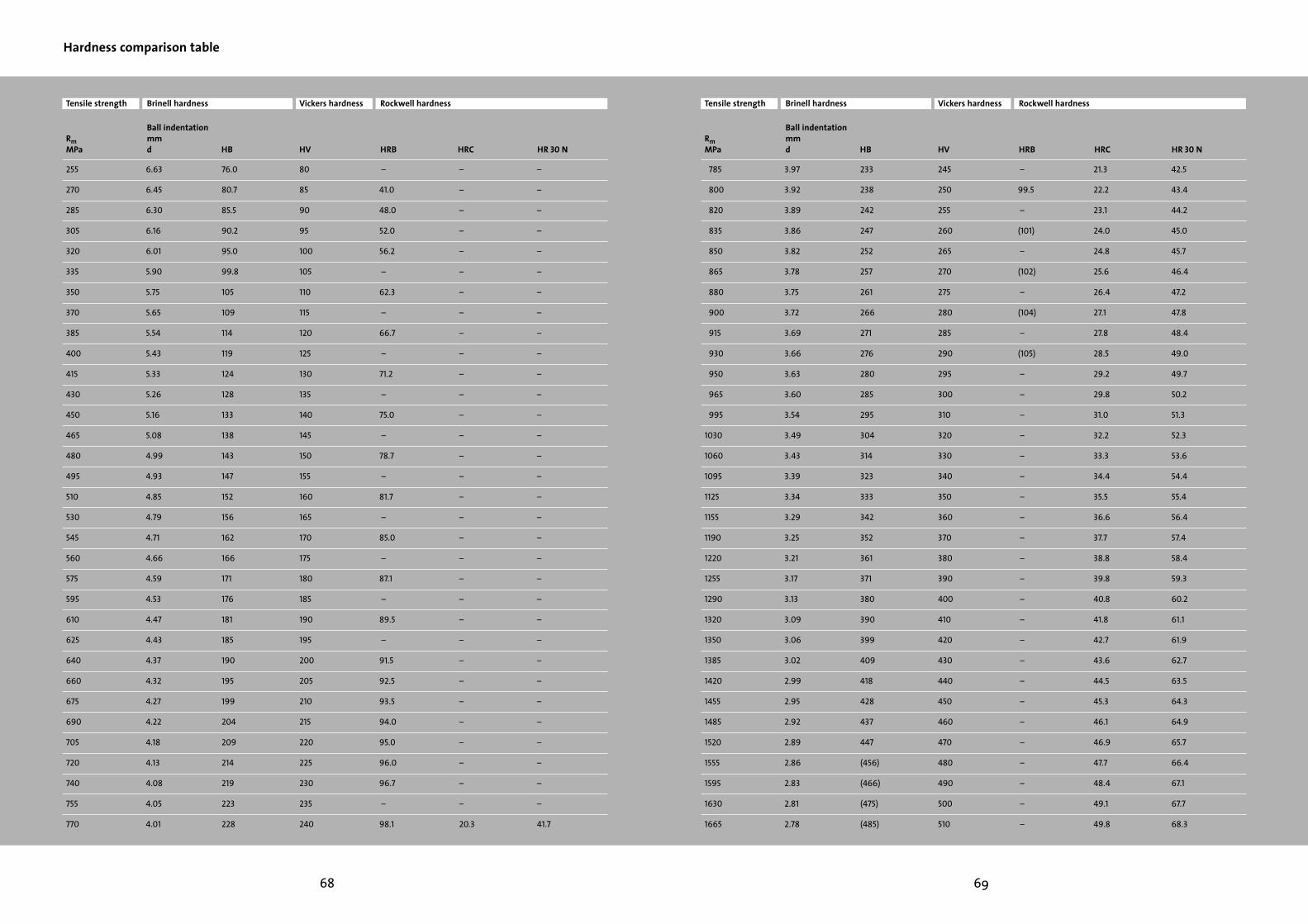
69
Tensile strength
RmMPa
Brinell hardness
Ball indentation mmd HB
Vickers hardness
HV
Rockwell hardness
HRB HRC HR 30 N
785 3.97 233 245 – 21.3 42.5
800 3.92 238 250 99.5 22.2 43.4
820 3.89 242 255 – 23.1 44.2
835 3.86 247 260 (101) 24.0 45.0
850 3.82 252 265 – 24.8 45.7
865 3.78 257 270 (102) 25.6 46.4
880 3.75 261 275 – 26.4 47.2
900 3.72 266 280 (104) 27.1 47.8
915 3.69 271 285 – 27.8 48.4
930 3.66 276 290 (105) 28.5 49.0
950 3.63 280 295 – 29.2 49.7
965 3.60 285 300 – 29.8 50.2
995 3.54 295 310 – 31.0 51.3
1030 3.49 304 320 – 32.2 52.3
1060 3.43 314 330 – 33.3 53.6
1095 3.39 323 340 – 34.4 54.4
1125 3.34 333 350 – 35.5 55.4
1155 3.29 342 360 – 36.6 56.4
1190 3.25 352 370 – 37.7 57.4
1220 3.21 361 380 – 38.8 58.4
1255 3.17 371 390 – 39.8 59.3
1290 3.13 380 400 – 40.8 60.2
1320 3.09 390 410 – 41.8 61.1
1350 3.06 399 420 – 42.7 61.9
1385 3.02 409 430 – 43.6 62.7
1420 2.99 418 440 – 44.5 63.5
1455 2.95 428 450 – 45.3 64.3
1485 2.92 437 460 – 46.1 64.9
1520 2.89 447 470 – 46.9 65.7
1555 2.86 (456) 480 – 47.7 66.4
1595 2.83 (466) 490 – 48.4 67.1
1630 2.81 (475) 500 – 49.1 67.7
1665 2.78 (485) 510 – 49.8 68.3
68
Tensile strength
RmMPa
Brinell hardness
Ball indentation mmd HB
Vickers hardness
HV
Rockwell hardness
HRB HRC HR 30 N
255 6.63 76.0 80 – – –
270 6.45 80.7 85 41.0 – –
285 6.30 85.5 90 48.0 – –
305 6.16 90.2 95 52.0 – –
320 6.01 95.0 100 56.2 – –
335 5.90 99.8 105 – – –
350 5.75 105 110 62.3 – –
370 5.65 109 115 – – –
385 5.54 114 120 66.7 – –
400 5.43 119 125 – – –
415 5.33 124 130 71.2 – –
430 5.26 128 135 – – –
450 5.16 133 140 75.0 – –
465 5.08 138 145 – – –
480 4.99 143 150 78.7 – –
495 4.93 147 155 – – –
510 4.85 152 160 81.7 – –
530 4.79 156 165 – – –
545 4.71 162 170 85.0 – –
560 4.66 166 175 – – –
575 4.59 171 180 87.1 – –
595 4.53 176 185 – – –
610 4.47 181 190 89.5 – –
625 4.43 185 195 – – –
640 4.37 190 200 91.5 – –
660 4.32 195 205 92.5 – –
675 4.27 199 210 93.5 – –
690 4.22 204 215 94.0 – –
705 4.18 209 220 95.0 – –
720 4.13 214 225 96.0 – –
740 4.08 219 230 96.7 – –
755 4.05 223 235 – – –
770 4.01 228 240 98.1 20.3 41.7
Hardness comparison table

70 71
Tensile strength
RmMPa
Brinell hardness
Ball indentation mmd HB
Vickers hardness
HV
Rockwell hardness
HRB HRC HR 30 N
1700 2.75 (494) 520 – 50.5 69.0
1740 2.73 (504) 530 – 51.1 69.5
1775 2.70 (513) 540 – 51.7 70.0
1810 2.68 (523) 550 – 52.3 70.5
1845 2.66 (532) 560 – 53.0 71.2
1880 2.63 (542) 570 – 53.6 71.7
1920 2.60 (551) 580 – 54.1 72.1
1955 2.59 (561) 590 – 54.7 72.7
1995 2.57 (570) 600 – 55.2 73.2
2030 2.54 (580) 610 – 55.7 73.7
2070 2.52 (589) 620 – 56.3 74.2
2105 2.51 (599) 630 – 56.8 74.6
2145 2.49 (608) 640 – 57.3 75.1
2180 2.47 (618) 650 – 57.8 75.5
– – – 660 – 58.3 75.9
– – – 670 – 58.8 76.4
– – – 680 – 59.2 76.8
– – – 690 – 59.7 77.2
– – – 700 – 60.1 77.6
– – – 720 – 61.0 78.4
– – – 740 – 61.8 79.1
– – – 760 – 62.5 79.7
– – – 780 – 63.3 80.4
– – – 800 – 64.0 81.1
– – – 820 – 64.7 81.7
– – – 840 – 65.3 82.2
– – – 860 – 65.9 82.7
– – – 880 – 66.4 83.1
– – – 900 – 67.0 83.6
– – – 920 – 67.5 84.0
– – – 940 – 68.0 84.4
Conversion of hardness values using this table are only approximate. See DIN 50 150, December 1976.
Hardness comparison table
Process and process parameters
Brinell hardness1)
1) calculated from:HB = 0.95 . HV
(0.102 F/D2 = 30)D = 10
Diameter of ball indentation in mm
Hardness value =
d
HB
Vickers hardness Diamond pyramidTest forces ≥ 50 N
HV
Rockwell hardness Ball 1.588 mm (1/16“)Total test force = 98 N
Diamond coneTotal test force = 1471 N
Diamond coneTotal test force = 294 N
HRB
HRC
HR 30 N
0.102 . 2 Fπ D(D – √D2 – d2)
General note (liability)All statements regarding the properties or utilization of the materials or products mentioned are for the purposes of description only.Guarantees regarding the existence of certain properties or a certain utilization are only ever valid if agreed upon in writing.