Embed Size (px)
Citation preview

Electricity and New Energy EDS® Solar Thermal
Multi-Loop Systems
Job Sheets - Instructor 52669-F0
Order no.: 52669-30 First Edition Revision level: 03/2017
By the staff of Festo Didactic
© Festo Didactic Ltée/Ltd, Quebec, Canada 2016 Internet: www.festo-didactic.com e-mail: [email protected]
Printed in Canada All rights reserved ISBN 978-2-89747-599-4 (Printed version) ISBN 978-2-89747-622-9 (CD-ROM) Legal Deposit – Bibliothèque et Archives nationales du Québec, 2016 Legal Deposit – Library and Archives Canada, 2016
The purchaser shall receive a single right of use which is non-exclusive, non-time-limited and limited geographically to use at the purchaser's site/location as follows.
The purchaser shall be entitled to use the work to train his/her staff at the purchaser’s site/location and shall also be entitled to use parts of the copyright material as the basis for the production of his/her own training documentation for the training of his/her staff at the purchaser’s site/location with acknowledgement of source and to make copies for this purpose. In the case of schools/technical colleges, training centers, and universities, the right of use shall also include use by school and college students and trainees at the purchaser’s site/location for teaching purposes.
The right of use shall in all cases exclude the right to publish the copyright material or to make this available for use on intranet, Internet and LMS platforms and databases such as Moodle, which allow access by a wide variety of users, including those outside of the purchaser’s site/location.
Entitlement to other rights relating to reproductions, copies, adaptations, translations, microfilming and transfer to and storage and processing in electronic systems, no matter whether in whole or in part, shall require the prior consent of Festo Didactic.
Information in this document is subject to change without notice and does not represent a commitment on the part of Festo Didactic. The Festo materials described in this document are furnished under a license agreement or a nondisclosure agreement.
Festo Didactic recognizes product names as trademarks or registered trademarks of their respective holders.
All other trademarks are the property of their respective owners. Other trademarks and trade names may be used in this document to refer to either the entity claiming the marks and names or their products. Festo Didactic disclaims any proprietary interest in trademarks and trade names other than its own.
© Festo Didactic 52669-30 III
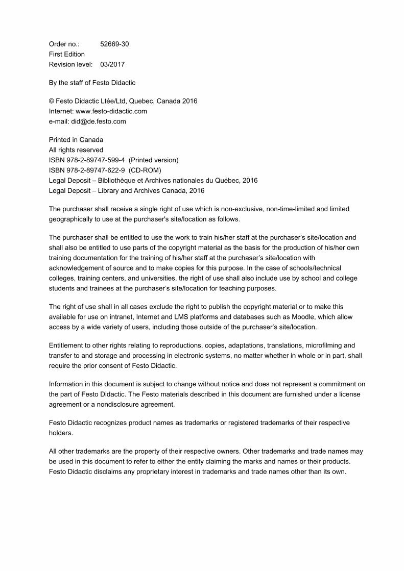
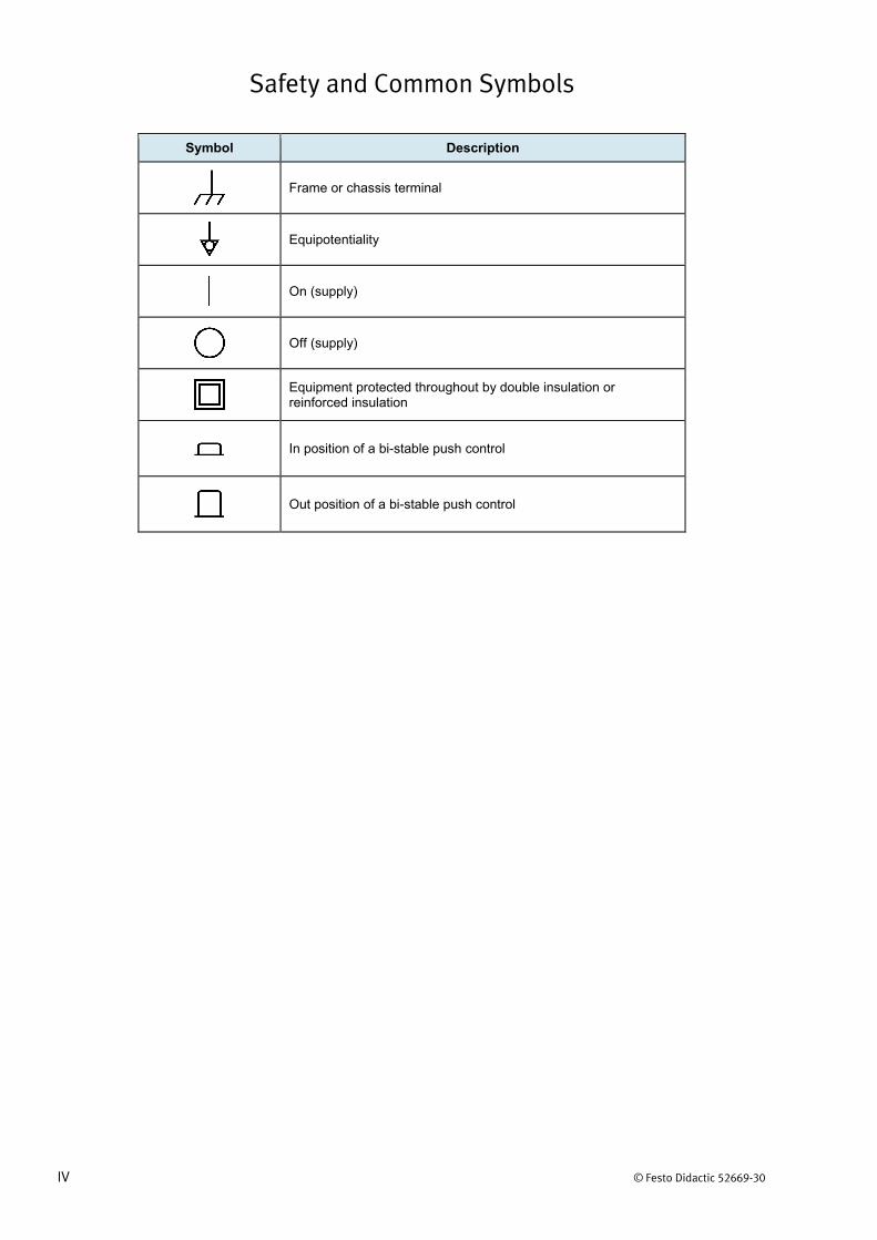
Safety and Common Symbols
The following safety and common symbols may be used in this manual and on the equipment:
Symbol Description
DANGER indicates a hazard with a high level of risk which, if not avoided, will result in death or serious injury.
WARNING indicates a hazard with a medium level of risk which, if not avoided, could result in death or serious injury.
CAUTION indicates a hazard with a low level of risk which, if not avoided, could result in minor or moderate injury.
CAUTION used without the Caution, risk of danger sign , indicates a hazard with a potentially hazardous situation which, if not avoided, may result in property damage.
Caution, risk of electric shock
Caution, hot surface
Caution, risk of danger. Consult the relevant user documentation.
Caution, lifting hazard
Caution, hand entanglement hazard
Notice, non-ionizing radiation
Direct current
Alternating current
Both direct and alternating current
Three-phase alternating current
Earth (ground) terminal
Protective conductor terminal
Safety and Common Symbols
IV © Festo Didactic 52669-30
Symbol Description
Frame or chassis terminal
Equipotentiality
On (supply)
Off (supply)
Equipment protected throughout by double insulation or reinforced insulation
In position of a bi-stable push control
Out position of a bi-stable push control
© Festo Didactic 52669-30 V
Table of Contents
Preface .................................................................................................................VII
About This Manual ................................................................................................ IX
To the Instructor .................................................................................................... XI
Job Sheet 1 Closed-Loop Water Heating ...................................................... 1
Job Sheet 2 Closed-Loop Surface Heating ................................................. 11
Job Sheet 3 Closed-Loop Air Heating ......................................................... 23
Job Sheet 4 Closed-Loop Drainback Systems ........................................... 37
Job Sheet 5 Closed-Loop Combination Systems ...................................... 55
Appendix A Equipment Utilization Chart .................................................... 67
Appendix B Safety Procedures .................................................................... 69
Appendix C System Filling and Draining Procedures ............................... 71
Appendix D Schematic Diagram Symbols .................................................. 85
Appendix E System Troubleshooting ......................................................... 91
Appendix F Electrical Wiring Instructions ................................................. 93
Appendix G Work Assessment table........................................................... 97

© Festo Didactic 52669-30 VII
Preface
The EDS® Solar Thermal, Model 46121, is a modular program that covers the history, fundamentals, installation, operation, maintenance, and servicing of solar thermal energy systems.
a From now on, the EDS® Solar Thermal will be referred to simply as the solar thermal training system.
The curriculum is divided into the following topics:
• Introduction to solar thermal energy
• Solar thermal energy systems
• Multi-loop systems
The solar thermal training system should be operated under supervision at all times. Never let the system operate unattended.
Be careful to prevent water from making contact with electrical components. Use a bucket and mop if some leakage occurs.
The surface of the work lights can become very hot. Whenever you manipulate them, take great care to avoid direct contact with the skin.
Be careful when rotating the solar collector. Improper use can lead to injuries.
The maximum operating temperature of the liquid inside the system is 50°C. If this temperature is reached, stop the system operation, turn the lights off, or cover the solar collector.
We invite readers of this manual to send us their tips, feedback, and suggestions for improving the book.
Please send these to [email protected].
The authors and Festo Didactic look forward to your comments.

© Festo Didactic 52669-30 IX
About This Manual
The topics covered in this manual are presented in the form of job sheets. The job sheets include a description of the objectives, a list of equipment required, a list of safety procedures, and a list of steps required to attain the objectives.
The topics are introduced in an Information Job Sheet. However, to obtain detailed information about the covered topic, you should refer to your textbook or ask your instructor to guide your learning process.
Safety considerations
Safety symbols that may be used in this manual and on the equipment are listed in the Safety Symbols table at the beginning of the manual.
Safety procedures related to the tasks that you will be asked to perform are indicated in each exercise.
Make sure that you are wearing appropriate protective equipment when performing the tasks. You should never perform a task if you have any reason to think that a manipulation could be dangerous for you or your teammates.
Reference material
Refer to the textbook titled Solar Water Heating written by Bob Ramlow & Benjamin Nusz.
Prerequisite
As a prerequisite to this course, you should have read the manuals titled Trainer Familiarization & Safety, p.n. 86515-20, Solar Module, p.n. 86516-20, and Wind Turbine, p.n. 86517-20.
Appendices
The appendices included in the manual are:
Appendix A: Equipment Utilization Chart, shows in which Job Sheet(s) the equipment is used.
Appendix B: Safety Procedures, lists the basic safety procedures to be performed before you begin any of the job sheets in this manual.
Appendix C: System Filling and Draining Procedures, contains system filling and draining procedures specific to the Solar Thermal Energy Training System.
Appendix D: Schematic Diagram Symbols, shows a variety of commonly used schematic symbols that represent electrical components that may appear in diagrams throughout this manual.
Appendix E: System Troubleshooting, lists common symptoms and causes of system failures.
Appendix F: Electrical Wiring Instructions, provides information on the electrical wiring of the training system.
About This Manual
X © Festo Didactic 52669-30
Appendix G: Work Assessment table, provides a table allowing the instructor to assess the students’ work in the exercises (Instructor Guide only).
Improvements
Equipment is constantly improved by manufacturers to maintain state-of-the-art quality. Therefore, you may discover some discrepancies between the instructions and/or graphics in the course and the actual equipment. To ensure correct setup and operation, always consult the latest equipment user guide.
© Festo Didactic 52669-30 XI
To the Instructor
You will find in this Instructor Guide all the elements included in the Student Manual together with the answers to all questions, results of measurements, graphs, explanations, suggestions, and, in some cases, instructions to help you guide the students through their learning process. All the information that applies to you is placed between markers and appears in red.
Accuracy of measurements
The numerical results of the hands-on exercises may differ from one student to another. For this reason, the results and answers given in this manual should be considered as a guide. Students who correctly performed the exercises should expect to demonstrate the principles involved and make observations and measurements similar to those given as answers.
Instructions
• Before a student begins a job sheet, ensure that the equipment is ingood condition and does not represent any risk when used.
• When a student has to complete a setup that is already partiallymounted, ensure that the setup corresponds to the job description.
• This guide provides you with the answers to calculations, measurements,and review questions. Your evaluation, however, must relate to thequality of the accomplished work. Make sure that the objectives listed inthe Work Assessment Table are met.
• When the jobs are performed in teams, ensure that each student hasand installs a padlock when performing the lockout/tagout procedure.
• Make sure that the students understand the objectives of the job to do.They should have read the appropriate pages in their textbook.

Sample
Extracted from
Job Sheets - Instructor

© Festo Didactic 52669-30 1
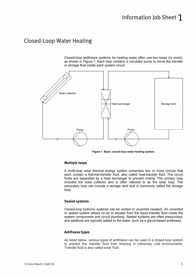
Closed-loop antifreeze systems for heating water often use two loops (or more), as shown in Figure 1. Each loop contains a circulator pump to move the transfer or storage fluid inside each system circuit.
Figure 1. Basic closed-loop water-heating system.
Multiple loops
A multi-loop solar thermal energy system comprises two or more circuits that each contain a thermal-transfer fluid, also called heat-transfer fluid. The circuit fluids are separated by a heat exchanger to prevent mixing. The primary loop includes the solar collector and is often referred to as the solar loop. The secondary loop can include a storage tank and is commonly called the storage loop.
Sealed systems
Closed-loop hydronic systems can be vented or unvented (sealed). An unvented or sealed system allows no air to escape from the liquid-transfer fluid inside the system components and circuit plumbing. Sealed systems are often pressurized, and additives are typically added to the water, such as a glycol-based antifreeze.
Antifreeze types
As listed below, various types of antifreeze can be used in a closed-loop system to prevent the transfer fluid from freezing in extremely cold environments. Transfer fluid is also called solar fluid.
Closed-Loop Water Heating
Information Job Sheet 1
Pump Pump
Heat exchanger
Solar collector
Storage tank
Job Sheet 1 – Closed-Loop Water Heating
2 © Festo Didactic 52669-30
Solar Fluids
• Water: freezes at 0°C or below.
• Propylene glycol-water mixture: a good thermal conductor that is safe to use.
• Ethylene glycol-water mixture: toxic, corrosive, and deteriorates quickly.
• Synthetic oil: a poor heat conductor that can destroy certain plastic components and rubber seals.
• Silicone oil: a poor heat conductor that can destroy certain plastic components and rubber seals.
The most common type of antifreeze used in solar thermal energy systems is high-temperature propylene glycol mixed with distilled water. This mixture reduces the potential for solar collectors and piping to freeze up and burst in very cold climates due to the thermal expansion of ice. Propylene glycol must always be diluted by a certain percentage of water, whose value depends on the freeze protection required by the particular climate. Cooler fluid is thicker and warmer fluid is more slippery. Either way, glycol is more difficult to pump through the system than ordinary water, which has an effect on the required pump size. Antifreeze manufacturers normally specify the freeze temperature at which the fluid gels, as well as the burst temperature at which the fluid solidifies completely. Proper mixture ratios are commonly specified by the glycol manufacturer as well. The antifreeze/water mixture should contain between 30% and 60% glycol.
a It is recommended to use the highest amount of water allowed for the required freeze-protection temperature.
Mixed solar fluid deteriorates over time and needs to be checked and replaced periodically. However, most high-quality propylene glycol solutions remain efficient for more than ten years in a typical installation.
System performance
This job sheet involves installing and operating a dual closed-loop water (DHW) heating system that uses an external heat exchanger with thermal storage, which has the following advantages and disadvantages.
System type
• Active, indirect, closed-loop, unvented, antifreeze (water) heating with storage and with an external heat exchanger
Advantages
• Solar fluid can be sent directly to heat exchanger
• Freeze-protected for all climates
• Without storage, only used when heating is required
Disadvantages
• Antifreeze can overheat; not for hot climates
• Without storage, needs a diversion load when heating is no longer required

© Festo Didactic 52669-30 3
In this job sheet, you will install a dual closed-loop water (DHW) heating system that includes thermal storage and can use antifreeze as part of a solar thermal energy system. The antifreeze system will exhibit the use of a heat exchanger that is external to the storage tank.
Equipment required
Refer to the Equipment Utilization Chart in Appendix A to obtain the list of equipment required for this job.
Safety procedures
Before proceeding with this job sheet, complete the following checklist.
You are wearing safety glasses.
You are wearing safety shoes.
You are not wearing anything that might get caught such as a tie, jewelry, or loose clothes.
If your hair is long, tie it out of the way.
The working area is clean and free of oil.
The floor is not wet.
Your sleeves are rolled up.
The wheels of the system are locked in place.
Closed-Loop Water Heating
Job Sheet 1
OBJECTIVE
PROCEDURE
Job Sheet 1 – Closed-Loop Water Heating
4 © Festo Didactic 52669-30
Installation
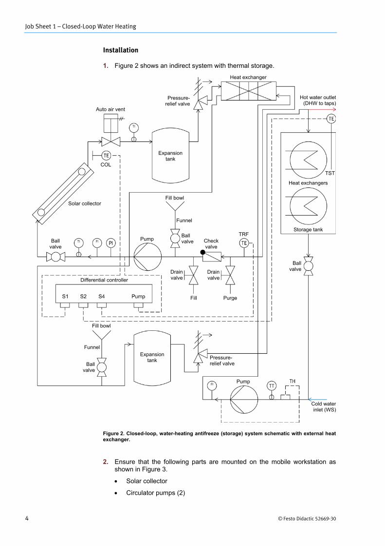
1. Figure 2 shows an indirect system with thermal storage.
Figure 2. Closed-loop, water-heating antifreeze (storage) system schematic with external heat exchanger.
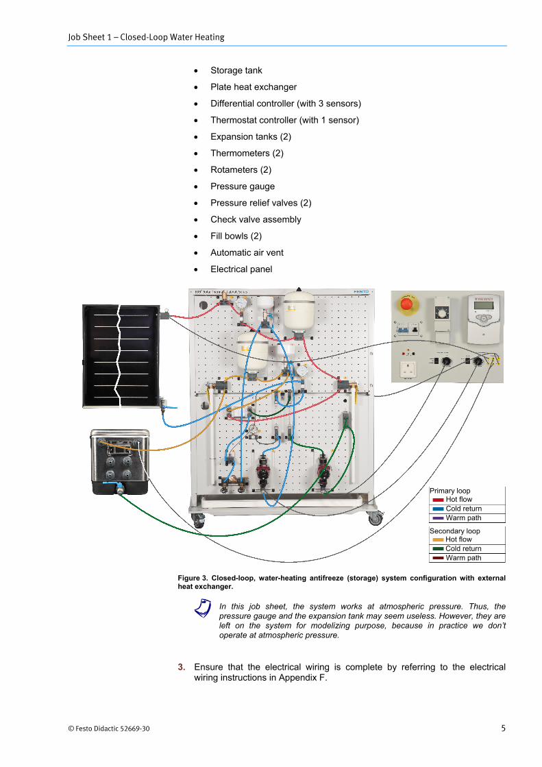
2. Ensure that the following parts are mounted on the mobile workstation as shown in Figure 3.
• Solar collector
• Circulator pumps (2)
Expansion tank
Auto air vent
Pressure-relief valve
Heat exchanger
Hot water outlet (DHW to taps)
TST
Heat exchangers
Storage tank
Ball valve
Fill Purge
Drain valve
Drain valve Differential controller
Pressure-relief valve Ball
valve
Funnel
Fill bowl
Expansion tank
Pump
Pump Ball valve
Funnel
Fill bowl
Check valve
Cold water inlet (WS)
Ball valve
Solar collector
COL
TRF
Job Sheet 1 – Closed-Loop Water Heating
© Festo Didactic 52669-30 5
• Storage tank
• Plate heat exchanger
• Differential controller (with 3 sensors)
• Thermostat controller (with 1 sensor)
• Expansion tanks (2)
• Thermometers (2)
• Rotameters (2)
• Pressure gauge
• Pressure relief valves (2)
• Check valve assembly
• Fill bowls (2)
• Automatic air vent
• Electrical panel
Figure 3. Closed-loop, water-heating antifreeze (storage) system configuration with external heat exchanger.
a In this job sheet, the system works at atmospheric pressure. Thus, the pressure gauge and the expansion tank may seem useless. However, they are left on the system for modelizing purpose, because in practice we don’t operate at atmospheric pressure.
3. Ensure that the electrical wiring is complete by referring to the electrical wiring instructions in Appendix F.
Primary loop
Secondary loop
Hot flow Cold return Warm path
Hot flow Cold return Warm path
Job Sheet 1 – Closed-Loop Water Heating
6 © Festo Didactic 52669-30
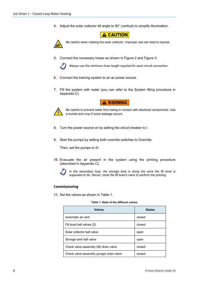
4. Adjust the solar collector tilt angle to 90° (vertical) to simplify illumination.
Be careful when rotating the solar collector. Improper use can lead to injuries.
5. Connect the necessary hoses as shown in Figure 2 and Figure 3.
a Always use the minimum hose length required for each circuit connection.
6. Connect the training system to an ac power source.
7. Fill the system with water (you can refer to the System filling procedure in Appendix C).
Be careful to prevent water from being in contact with electrical components. Use a bucket and mop if some leakage occurs.
8. Turn the power source on by setting the circuit breaker to I.
9. Start the pumps by setting both override switches to Override.
Then, set the pumps to III.
10. Evacuate the air present in the system using the priming procedure (described in Appendix C).
a In the secondary loop, the storage tank is doing the work the fill bowl is supposed to do. Hence, close the fill bowl’s valve to perform the priming.
Commissioning
11. Set the valves as shown in Table 1.
Table 1. State of the different valves.
Valves States
Automatic air vent closed
Fill bowl ball valves (2) closed
Solar collector ball valve open
Storage tank ball valve open
Check valve assembly (fill) drain valve closed
Check valve assembly (purge) drain valve closed
Job Sheet 1 – Closed-Loop Water Heating
© Festo Didactic 52669-30 7
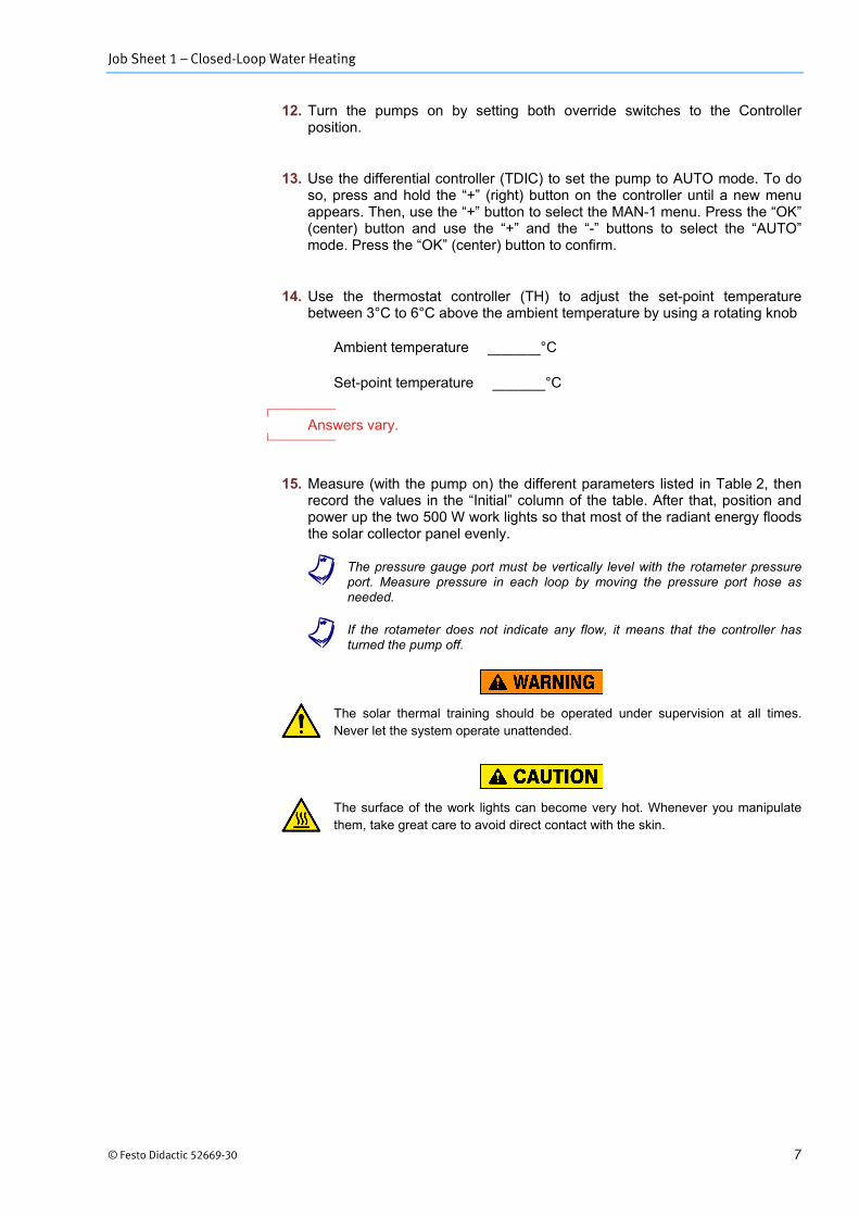
12. Turn the pumps on by setting both override switches to the Controller position.
13. Use the differential controller (TDIC) to set the pump to AUTO mode. To do so, press and hold the “+” (right) button on the controller until a new menu appears. Then, use the “+” button to select the MAN-1 menu. Press the “OK” (center) button and use the “+” and the “-” buttons to select the “AUTO” mode. Press the “OK” (center) button to confirm.
14. Use the thermostat controller (TH) to adjust the set-point temperature between 3°C to 6°C above the ambient temperature by using a rotating knob
Ambient temperature = °C
Set-point temperature = °C
Answers vary.
15. Measure (with the pump on) the different parameters listed in Table 2, then record the values in the “Initial” column of the table. After that, position and power up the two 500 W work lights so that most of the radiant energy floods the solar collector panel evenly.
a The pressure gauge port must be vertically level with the rotameter pressure port. Measure pressure in each loop by moving the pressure port hose as needed.
a If the rotameter does not indicate any flow, it means that the controller has turned the pump off.
The solar thermal training should be operated under supervision at all times. Never let the system operate unattended.
The surface of the work lights can become very hot. Whenever you manipulate them, take great care to avoid direct contact with the skin.
Job Sheet 1 – Closed-Loop Water Heating
8 © Festo Didactic 52669-30
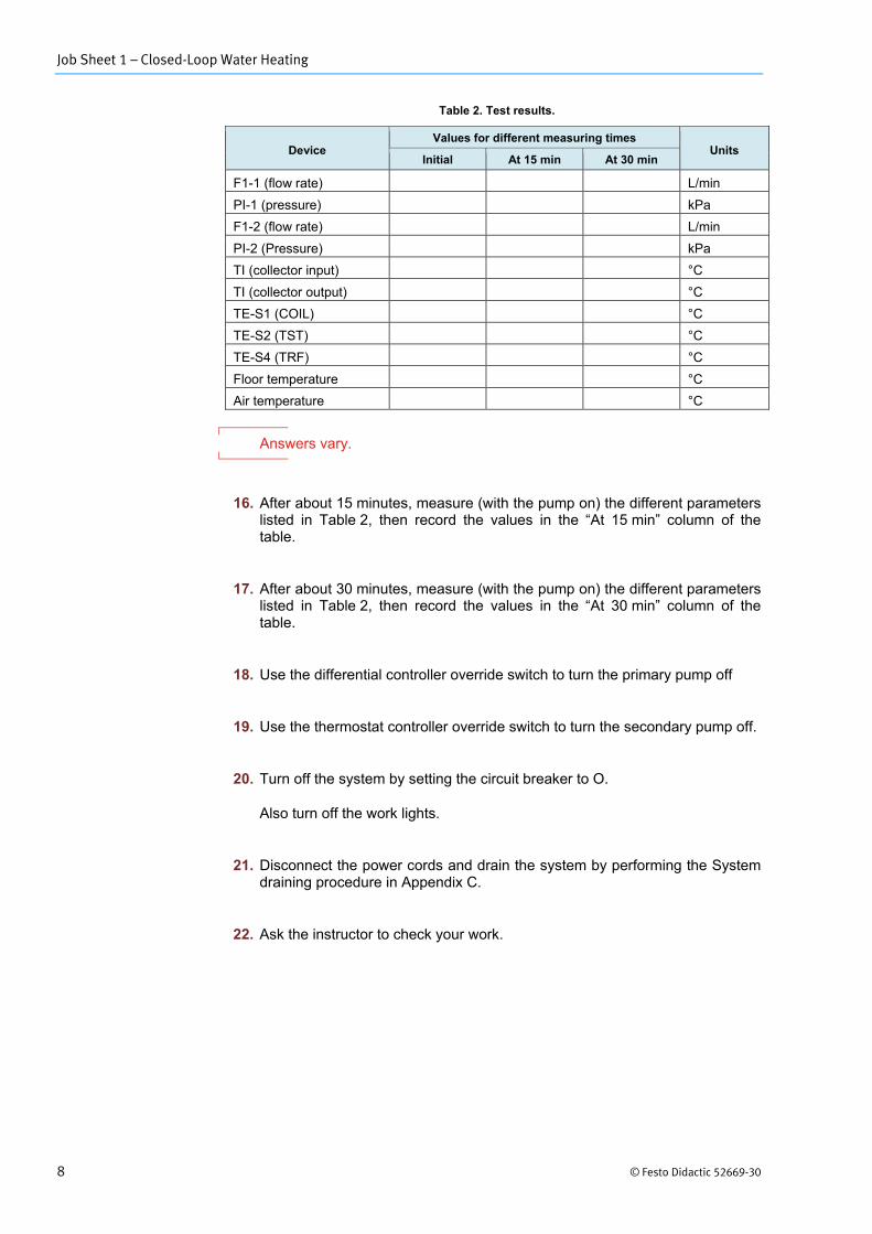
Table 2. Test results.
Device Values for different measuring times
Units Initial At 15 min At 30 min
F1-1 (flow rate) L/min PI-1 (pressure) kPa F1-2 (flow rate) L/min PI-2 (Pressure) kPa TI (collector input) °C TI (collector output) °C TE-S1 (COIL) °C TE-S2 (TST) °C TE-S4 (TRF) °C Floor temperature °C Air temperature °C
Answers vary.
16. After about 15 minutes, measure (with the pump on) the different parameters listed in Table 2, then record the values in the “At 15 min” column of the table.
17. After about 30 minutes, measure (with the pump on) the different parameters listed in Table 2, then record the values in the “At 30 min” column of the table.
18. Use the differential controller override switch to turn the primary pump off
19. Use the thermostat controller override switch to turn the secondary pump off.
20. Turn off the system by setting the circuit breaker to O.
Also turn off the work lights.
21. Disconnect the power cords and drain the system by performing the System draining procedure in Appendix C.
22. Ask the instructor to check your work.
Job Sheet 1 – Closed-Loop Water Heating
© Festo Didactic 52669-30 9
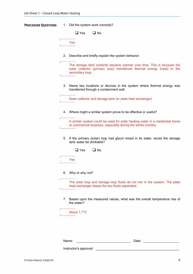
1. Did the system work correctly?
Yes No
Yes
2. Describe and briefly explain the system behavior.
The storage tank contents became warmer over time. This is because the solar collector (primary loop) transferred thermal energy (heat) to the secondary loop.
3. Name two locations or devices in the system where thermal energy was transferred through a containment wall.
Solar collector and storage tank (or plate heat exchanger)
4. Where might a similar system prove to be effective or useful?
A similar system could be used for solar heating water in a residential home or commercial business, especially during the winter months.
5. If the primary (solar) loop had glycol mixed in its water, would the storage tank water be drinkable?
Yes No
Yes
6. Why or why not?
The solar loop and storage loop fluids do not mix in the system. The plate heat exchanger keeps the two fluids separated.
7. Based upon the measured values, what was the overall temperature rise of the water?
About 1.7°C
PROCEDURE QUESTIONS
Name: ______________________________ Date: ____________________
Instructor's approval: ______________________________________________