Embed Size (px)
Citation preview
8/7/2019 eeconclusion
http://slidepdf.com/reader/full/eeconclusion 1/6
CONCLUSION:
After we finished performing Experiment 1 which is RMS Value of an A.C. Sinusoidal
Waveform we have accomplished our objective that to investigate the RMS value of an A.C.
Sinusoidal Waveform and the power consumed by the circuit.
We have understand that the heat produced in a circuit by an A.C. source is also the same
produced in an D.C. source in the same given circuit.
As for the first part of the experiment observing the complete circuit and having the
source as D.C. the waveform that we can see at the oscilloscope is a straight line waveform,
simply because there is an direct current flowing in the circuit meaning it is an stable current, it
comes from a process from an A.C. source through a designed circuit up to filtering to have a
stable current. We need this stable current in most of our appliances to avoid problems.
And for the second part of the experiment we compared the current coming from an A.C.
source and a D.C. source using a lamp. Setting up the circuit we adjust the potentiometer to have
the lamp produce the same amount light coming from an A.C. and D.C. source, and after
comparing the two we can observe that their current meets or almost the same but the current at
the A.C. source is always varying simply because it is not an stable current it is an Alternating
current and we can see at the oscilloscope that the waveform produced is a sinusoidal waveformwith a peak to peak value, it considers the positive half cycle and the negative half cycle making
it a complete cycle. Comparing the waveform at the D.C. source we conclude that a stable
straight line waveform is best to use rather than a fluctuating sinusoidal source. Using this
fluctuating sinusoidal waveform to a personal computer for an example the computer might have
problems and end up to ruining the circuitry inside it because the current flowing in to it is not
stable and most of the new devices get damage if the coming current is fluctuating.
DISCUSSION and INFORMATION:
Alternating Current vs. Direct Current
8/7/2019 eeconclusion
http://slidepdf.com/reader/full/eeconclusion 2/6
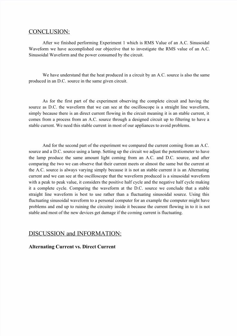
The figure to the right shows the schematic diagram of a very basic DC circuit. It consists of
nothing more than a source (a producer of electrical energy) and a load (whatever is to be powered by that electrical energy). The source can be any electrical source: a chemical battery,
an electronic power supply, a mechanical generator, or any other possible continuous source of electrical energy. For simplicity, we represent the source in this figure as a battery.
At the same time, the load can be any electrical load: a light bulb, electronic clock or watch,
electronic instrument, or anything else that must be driven by a continuous source of electricity.The figure here represents the load as a simple resistor.
Regardless of the specific source and load in this circuit, electrons leave the negative terminal of the source, travel through the circuit in the direction shown by the arrows, and eventually return
to the positive terminal of the source. This action continues for as long as a complete electricalcircuit exists.
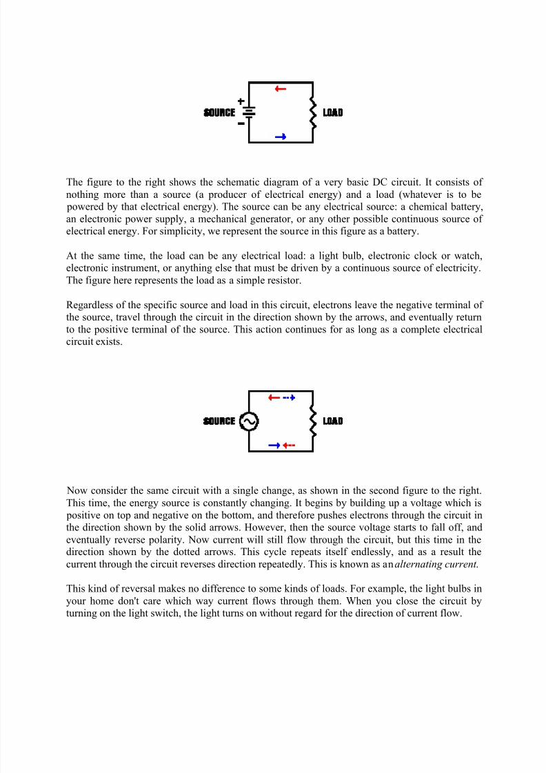
Now consider the same circuit with a single change, as shown in the second figure to the right.
This time, the energy source is constantly changing. It begins by building up a voltage which is
positive on top and negative on the bottom, and therefore pushes electrons through the circuit inthe direction shown by the solid arrows. However, then the source voltage starts to fall off, and
eventually reverse polarity. Now current will still flow through the circuit, but this time in thedirection shown by the dotted arrows. This cycle repeats itself endlessly, and as a result the
current through the circuit reverses direction repeatedly. This is known as an alternating current .
This kind of reversal makes no difference to some kinds of loads. For example, the light bulbs in
your home don't care which way current flows through them. When you close the circuit byturning on the light switch, the light turns on without regard for the direction of current flow.
8/7/2019 eeconclusion
http://slidepdf.com/reader/full/eeconclusion 3/6
Properties of Alternating Current
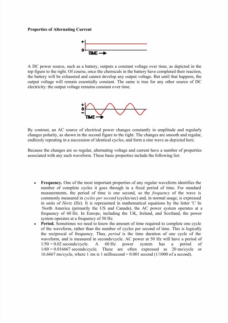
A DC power source, such as a battery, outputs a constant voltage over time, as depicted in the
top figure to the right. Of course, once the chemicals in the battery have completed their reaction,the battery will be exhausted and cannot develop any output voltage. But until that happens, the
output voltage will remain essentially constant. The same is true for any other source of DCelectricity: the output voltage remains constant over time.
By contrast, an AC source of electrical power changes constantly in amplitude and regularlychanges polarity, as shown in the second figure to the right. The changes are smooth and regular,endlessly repeating in a succession of identical cycles, and form a sine wave as depicted here.
Because the changes are so regular, alternating voltage and current have a number of properties
associated with any such waveform. These basic properties include the following list:
y Frequency. One of the most important properties of any regular waveform identifies the
number of complete cycles it goes through in a fixed period of time. For standardmeasurements, the period of time is one second, so the f requency of the wave is
commonly measured in cycles per second (cycles/sec) and, in normal usage, is expressedin units of Hertz (Hz). It is represented in mathematical equations by the letter 'f.' In
North America (primarily the US and Canada), the AC power system operates at afrequency of 60 Hz. In Europe, including the UK, Ireland, and Scotland, the power
system operates at a frequency of 50 Hz. y Period. Sometimes we need to know the amount of time required to complete one cycle
of the waveform, rather than the number of cycles per second of time. This is logicallythe reciprocal of frequency. Thus, period is the time duration of one cycle of the
waveform, and is measured in seconds/cycle. AC power at 50 Hz will have a period of 1/50 = 0.02 seconds/cycle. A 60 Hz power system has a period of
1/60 = 0.016667 seconds/cycle. These are often expressed as 20 ms/cycle or 16.6667 ms/cycle, where 1 ms is 1 millisecond = 0.001 second (1/1000 of a second).
8/7/2019 eeconclusion
http://slidepdf.com/reader/full/eeconclusion 4/6
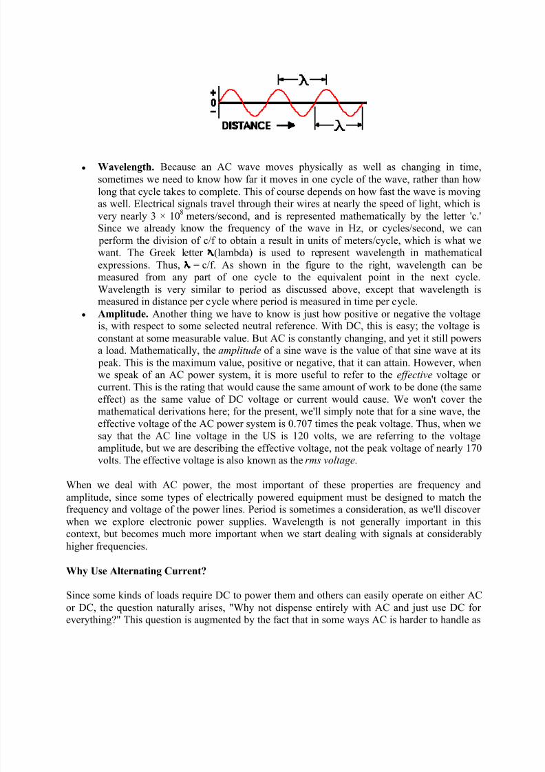
y Wavelength. Because an AC wave moves physically as well as changing in time,
sometimes we need to know how far it moves in one cycle of the wave, rather than how
long that cycle takes to complete. This of course depends on how fast the wave is movingas well. Electrical signals travel through their wires at nearly the speed of light, which is
very nearly 3 × 10⁸
meters/second, and is represented mathematically by the letter 'c.'Since we already know the frequency of the wave in Hz, or cycles/second, we can
perform the division of c/f to obtain a result in units of meters/cycle, which is what wewant. The Greek letter (lambda) is used to represent wavelength in mathematical
expressions. Thus, = c/f. As shown in the figure to the right, wavelength can bemeasured from any part of one cycle to the equivalent point in the next cycle.
Wavelength is very similar to period as discussed above, except that wavelength ismeasured in distance per cycle where period is measured in time per cycle.
y Amplitude. Another thing we have to know is just how positive or negative the voltageis, with respect to some selected neutral reference. With DC, this is easy; the voltage is
constant at some measurable value. But AC is constantly changing, and yet it still powersa load. Mathematically, the amplitude of a sine wave is the value of that sine wave at its
peak. This is the maximum value, positive or negative, that it can attain. However, whenwe speak of an AC power system, it is more useful to refer to the e ff ective voltage or current. This is the rating that would cause the same amount of work to be done (the same
effect) as the same value of DC voltage or current would cause. We won't cover themathematical derivations here; for the present, we'll simply note that for a sine wave, the
effective voltage of the AC power system is 0.707 times the peak voltage. Thus, when wesay that the AC line voltage in the US is 120 volts, we are referring to the voltage
amplitude, but we are describing the effective voltage, not the peak voltage of nearly 170volts. The effective voltage is also known as the rms voltage.
When we deal with AC power, the most important of these properties are frequency and
amplitude, since some types of electrically powered equipment must be designed to match thefrequency and voltage of the power lines. Period is sometimes a consideration, as we'll discover
when we explore electronic power supplies. Wavelength is not generally important in thiscontext, but becomes much more important when we start dealing with signals at considerably
higher frequencies.
Why Use Alternating Current?
Since some kinds of loads require DC to power them and others can easily operate on either AC
or DC, the question naturally arises, "Why not dispense entirely with AC and just use DC for everything?" This question is augmented by the fact that in some ways AC is harder to handle as
8/7/2019 eeconclusion
http://slidepdf.com/reader/full/eeconclusion 5/6
well as to use. Nevertheless, there is a very practical reason, which overrides all other considerations for a widely distributed power grid. It all boils down to a question of cost.
DC does get used in some local commercial applications. An excellent example of this is the
electric trolley car and trolley bus system used in San Francisco, for public transportation.
Trolley cars are electric train cars with power supplied by an overhead wire. Trolley busses arelike any other bus, except they are electrically powered and get their power from two overheadwires. In both cases, they operate on 600 volts DC, and the overhead wires span the city.
The drawback is that most of the electrical devices on each car or bus, including all the light
bulbs inside, are quite standard and require 110 to 120 volts. At the same time, however, if wewere to reduce the system voltage, we would have to increase the amount of current drawn by
each car or bus in order to provide the same amount of power to it. (Power is equal to the productof the applied voltage and the resulting current: P = I × E.) But those overhead wires are not
perfect conductors; they exhibit some resistance. They will absorb some energy from theelectrical current and dissipate it as waste heat, in accordance with Ohm's Law (E = I × R). With
a small amount of algebra, we can note that the lost power can be expressed as:
P lost = I²R
Now, if we reduce the voltage by a factor of 5 (to 120 volts DC), we must increase the current bya factor of 5 to maintain the same power to the trolley car or bus. But lost power is a function of
the square of the current, so we will lose not five times as much power in the resistance of thewires, but twenty- f ive times as much power. To offset and minimize that loss, we would have to
use much larger wires, and pay a high price for all that extra copper. A cheaper solution is tomount a motor-generator set in each trolley car and bus, using a 600 volt dc motor and a lower-
voltage generator to power all the equipment aboard that car.
The same reality of Ohm's Law and resistive losses holds true in the country-wide power distribution system. We need to keep the voltage used in homes to a reasonable and relatively
safe value, but at the same time we need to minimize resistive losses in the transmission wires,without bankrupting ourselves buying heavy-gauge copper wire. At the same time, we can't use
motor-generator pairs all across the country; they would need constant service and would break down far too often. We need a system that allows us to raise the voltage (and thus reduce the
current) for long-distance transmission, and then reduce the voltage again (to a safe value) for distribution to individual homes and businesses. And we need to do this without requiring any
moving parts to break down or need servicing.
The answer is to use an AC power system and transformers. (We'll learn far more abouttransformers in a later page; for now, a trans f ormer is an electrical component that can convertincoming AC power at one voltage to outgoing power at a different voltage, higher or lower,
with only very slight losses.) Thus, we can generate electricity at a reasonable voltage for practical AC generators (sometimes called alternators), then use transformers to step that voltage
up to very high levels for long-distance transmission, and then use additional transformers to stepthat high voltage back down for local distribution to individual homes.

8/7/2019 eeconclusion
http://slidepdf.com/reader/full/eeconclusion 6/6
In practice, this is done in stages. The really high-voltage transmission lines hanging from longglass insulators on the arms of tall steel towers carry electricity cross-country at several hundred
thousand volts. This is stepped down to about 22,000 volts for distribution to multiple neighbour hoods these are the wires you see at the top of the telephone poles in many areas. Additional
transformers mounted on some of these telephone poles step this voltage down again for
distribution to several homes each.
The design of the system minimizes the overall cost by balancing the cost of transformers against
the cost of heavier-gauge copper wire, as well as the cost of maintaining the system and repairingdamage. This is how the cost of electricity delivered to your home or business is kept to a
minimum, while maintaining a very high level of service.


