Embed Size (px)
Citation preview
International Journal of Petroleum and Petrochemical Engineering (IJPPE)
Volume 3, Issue 2, 2017, PP 23-35
ISSN 2454-7980 (Online)
DOI: http://dx.doi.org/10.20431/2454-7980.0302004
www.arcjournals.org
©ARC Page | 23
Effect of Using Polymer Buffer on Efficiency of Crude Oil
Recovery by Ionic Liquids
Omer A. Omer1, Mostafa M. Kinawy
1, 2, and Mohammed A. Khamis
1
1Petroleum and Natural Gas Engineering Department, College of Engineering, King Saud University,
Saudi Arabia2Mining and Petroleum Engineering Department, Faculty of Engineering, Al-Azhar University
Abstract: Ionic liquids have attracted attention in lowering the interfacial tension between oil and water.
Several researches were conducted on these materials and possibility of using them in enhanced oil recovery. In
this paper, the effect of using a polymer buffer behind a slug size of ionic liquid during flooding was
investigated. Ionic liquid solution was prepared with suitable concentration and salinity. Partially Hydrolyzed
Polyacrylamide Polymer (HPAM) was used in preparing polymer solutions. Core flooding runs were performed
using slug sizes of ionic liquid followed by polymer buffers having different slug sizes, polymer concentrations,
salinities, temperatures and injection rates. The results showed that an injection of a polymer buffer after a slug
size of ionic liquid increased the amount of the produced oil significantly. The larger polymer buffer slug size,
the larger amount of produced oil. Increasing of salinity and injection rate greatly affect polymer efficiency in
the improvement of oil recovery. Rising of polymer concentration may plug the pores and as a result, the
amount of oil recovery is not a considerable. Although, increasing of temperature decreases oil viscosity and
enhances ionic liquid efficiency, the temperature accelerates polymer thermal degradation and consequently
lowers the ultimate oil recovery. High injection rate causes mechanical polymer degradation and displacing
fluid bypass over oil, consequently low oil recovery can be obtained.
1. INTRODUCTION
Polymers are widely used as chemicals in oil industry especially in oil recovery and it is characterized
by availability and solubility in water. Polymer flooding is a very mature method with more than 40
years of applications(Abidin, Puspasari et al. 2012). It has been proven that they are effective in
recovering unswept oil by improving the mobility ratio(Abidin, Puspasari et al. 2012). There are three
potential ways in which polymer flooding makes the oil recovery process more efficient(Abidin,
Puspasari et al. 2012):
• Through the effects of polymers on fractional flow.
• By decreasing the water/oil mobility ratio.
• By diverting injected water from zones that have been swept.
The viscosity of a polymer solution is a measure of how "thick" a fluid is and how to resist to flow.
For example, honey is characterized as being "thicker" and more viscous than water. The viscosity-
improving power of a polymer depends on the size and extension of the polymer molecule in a certain
aqueous solution(Sorbie 1991). Due to many reasons, the measured viscosity of a polymer solution in
a viscometer and the effective viscosity of the polymer solution that is measured during flow through
porous media often have different values. Different types of polymers that succeed to accommodate
the wide variety of conditions encountered in oil fields over the world include the following:
- Polyacrylamides
Always, a synthetic polymer means polyacrylamides. A variety of these are produced by many
manufactures. Partially hydrolyzed polyacrylamide (HPAM) is one of the polyacrylamide
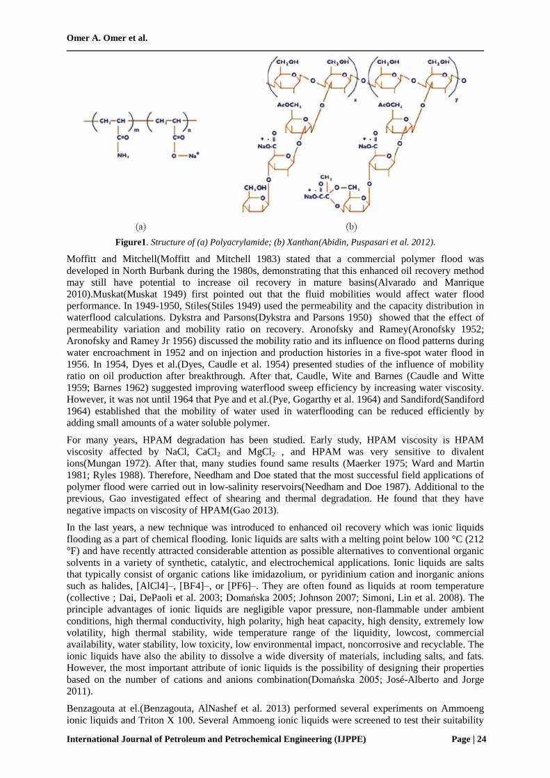
group(Abidin, Puspasari et al. 2012). Figure1.a shows the structure of the polyacrylamide.
- Xanthan Gum/Biopolymer
Xanthan gum is a polysaccharide or usually called as biopolymer. The biopolymer is an extracellular
slime, which forms on the surface of the cells. The fermented broth is pasteurized to prohibit the
microbes and precipitated from the broth by alcohol, then concentrated(Abidin, Puspasari et al. 2012).
The structure of the Xanthan gum is shown in Figure1.b.
Omer A. Omer et al.
International Journal of Petroleum and Petrochemical Engineering (IJPPE) Page | 24
Figure1. Structure of (a) Polyacrylamide; (b) Xanthan(Abidin, Puspasari et al. 2012).
Moffitt and Mitchell(Moffitt and Mitchell 1983) stated that a commercial polymer flood was
developed in North Burbank during the 1980s, demonstrating that this enhanced oil recovery method
may still have potential to increase oil recovery in mature basins(Alvarado and Manrique
2010).Muskat(Muskat 1949) first pointed out that the fluid mobilities would affect water flood
performance. In 1949-1950, Stiles(Stiles 1949) used the permeability and the capacity distribution in
waterflood calculations. Dykstra and Parsons(Dykstra and Parsons 1950) showed that the effect of
permeability variation and mobility ratio on recovery. Aronofsky and Ramey(Aronofsky 1952;
Aronofsky and Ramey Jr 1956) discussed the mobility ratio and its influence on flood patterns during
water encroachment in 1952 and on injection and production histories in a five-spot water flood in
1956. In 1954, Dyes et al.(Dyes, Caudle et al. 1954) presented studies of the influence of mobility
ratio on oil production after breakthrough. After that, Caudle, Wite and Barnes (Caudle and Witte
1959; Barnes 1962) suggested improving waterflood sweep efficiency by increasing water viscosity.
However, it was not until 1964 that Pye and et al.(Pye, Gogarthy et al. 1964) and Sandiford(Sandiford
1964) established that the mobility of water used in waterflooding can be reduced efficiently by
adding small amounts of a water soluble polymer.
For many years, HPAM degradation has been studied. Early study, HPAM viscosity is HPAM
viscosity affected by NaCl, CaCl2 and MgCl2 , and HPAM was very sensitive to divalent
ions(Mungan 1972). After that, many studies found same results (Maerker 1975; Ward and Martin
1981; Ryles 1988). Therefore, Needham and Doe stated that the most successful field applications of
polymer flood were carried out in low-salinity reservoirs(Needham and Doe 1987). Additional to the
previous, Gao investigated effect of shearing and thermal degradation. He found that they have
negative impacts on viscosity of HPAM(Gao 2013).
In the last years, a new technique was introduced to enhanced oil recovery which was ionic liquids
flooding as a part of chemical flooding. Ionic liquids are salts with a melting point below 100 °C (212
°F) and have recently attracted considerable attention as possible alternatives to conventional organic
solvents in a variety of synthetic, catalytic, and electrochemical applications. Ionic liquids are salts
that typically consist of organic cations like imidazolium, or pyridinium cation and inorganic anions
such as halides, [AlCl4]–, [BF4]–, or [PF6]–. They are often found as liquids at room temperature
(collective ; Dai, DePaoli et al. 2003; Domańska 2005; Johnson 2007; Simoni, Lin et al. 2008). The
principle advantages of ionic liquids are negligible vapor pressure, non-flammable under ambient
conditions, high thermal conductivity, high polarity, high heat capacity, high density, extremely low
volatility, high thermal stability, wide temperature range of the liquidity, lowcost, commercial
availability, water stability, low toxicity, low environmental impact, noncorrosive and recyclable. The
ionic liquids have also the ability to dissolve a wide diversity of materials, including salts, and fats.
However, the most important attribute of ionic liquids is the possibility of designing their properties
based on the number of cations and anions combination(Domańska 2005; José-Alberto and Jorge
2011).
Benzagouta at el.(Benzagouta, AlNashef et al. 2013) performed several experiments on Ammoeng
ionic liquids and Triton X 100. Several Ammoeng ionic liquids were screened to test their suitability
Effect of Using Polymer Buffer on Efficiency of Crude Oil Recovery by Ionic Liquids
International Journal of Petroleum and Petrochemical Engineering (IJPPE) Page | 25
for use in EOR. The screening was based on solubility in water or brine, e.g. 10 wt% NaCl in water.
Interfacial tension values measurement were taken for the successful ionic liquids. The studied
concentrations of ionic liquids were 0, 100, 200, 500, and 2,000 ppm. The used surfactant was Triton
X 100 and the ionic liquid used after screening was Ammoeng 102. They measured interfacial tension
at different temperature ranged from 23 ºC to 90 ºC. The interfacial tension measurements were taken.
The Saudi crude oil sample was used in this study. They found that most of the Ammoeng ionic
liquids were soluble in water and in brine. Also Interfacial tension of Ammoeng 102 in 10 wt% NaCl
brine is much smaller than that for any other tested Ammoeng ionic liquids. interfacial tension values
decrease with the increase of temperature and reach as low as 2.3 mN/m at reservoir temperature. The
interfacial tension values decrease with the increase of ionic liquid concentration at the same
temperature. Interfacial tension value of the ionic liquid in brine is much smaller than that in
deionized water at the same conditions. They concluded that some of the tested ionic liquids gave
very high interfacial tension values, even at high concentration of the ionic liquid. Moreover, the
measured interfacial tension increased with the increase of temperature. In all cases, the interfacial
tension values decreased with the increase of ionic liquid concentration. Ammoeng 102 gave the least
interfacial tension values, which decreased with the increase of temperature.
Bin Dahbag and others(Bin-Dahbag 2013; Bin-Dahbag, Al-Quraishi et al. 2014; M. S. Bin-Dahbag,
A. A. Al-Quraishi et al. 2014) performed a screening process on several ionic liquids, based on ionic
liquid solubility in brine at different salinities and distilled water, thermal stability and their
effectiveness in lowering aqueous-oleic phases interfacial tension at different temperatures. These
used brines are brine I (100% NaCl), brine II (95% NaCl and 5% CaCl2), and brine III (83% NaCl and
17% CaCl2).They found that Ammoeng 102 was the only ionic liquid soluble in all aqueous phases
tested with significant ability to lower interfacial tension at increasing temperatures. The obtained
results prove that Ammoeng 102 possesses high capability to lower surface tensions and this can be
related to its cationic nature with positive charges that are neutralized by the brine negatively charged
ions leading to easier accumulation of ionic liquids molecules at the oil-brine interface, causing more
interfacial tension reduction. They perfomermed several flooding runs using IL. They concloded that
an injection of IL as a slug at starting of flooding is better than ijection of IL as a tertiary flooding.
In oil industry, sometimes more than one method are performed together to increase the efficiency of
crude oil recovery because each method has its mechanism in increasing the efficiency of the crude oil
recovery. Therefore, a combination of flooding processes is performed. In this study, solution of ionic
liquids will was at optimum concentrations based on previous studies(Bin-Dahbag 2013,Bin-Dahbag,
Al-Quraishi et al. 2014; M. S. Bin-Dahbag, A. A. Al-Quraishi et al. 2014). In addition, polymers
solutions were prepared at different concentrations, salinities. Different flooding scenarios will be
performed using polymer buffers in different scenarios to study factors affecting on ionic liquid
flooding.
2. EXPERIMENTAL WORK
2.1. Materials
Many chemicals were used in this study to prepare brine, ionic liquid solution and polymer solutions.
The following chemicals were used in the experimental work:
Fresh water (H2O)
To insure accurate concentrations of both saline water and ionic liquid and polymersolutions, fresh
water was used as a solvent in preparing of these solutions. This water was produced from tap water
using filtration machine.
Sodium Chloride (NaCl)
Calcium Chloride (CaCl2)
The main anion dissolved in the brine is chloride (Cl-), while the main cations are Sodium (Na
+) and
Calcium (Ca++
)(Basyoni 2009). These ions are dissolved in the brine with many other ions (cations
like potassium (K+) and Magnesium (Mg
++) and anions like Bicarbonates (HCO3
−) and Sulfates (SO4
--
). The total summation of these ions called TDS. The ions other than Sodium (Na+), Calcium (Ca
++)
and chloride (Cl-), represent a very small amount in the total dissolved solid(Basyoni 2009). Because
of that, they were neglected during preparation of the brine. High purity Sodium Chloride and
Calcium Chloride were dissolved in fresh water to simulate the brine in Saudi Arabia.
Omer A. Omer et al.
International Journal of Petroleum and Petrochemical Engineering (IJPPE) Page | 26
Tetra-alkyl ammonium sulfate
Tetra-alkyl ammonium sulfate commercially is known as Ammoeng 102. It’s an ammonium based
ionic liquid and soluble in distilled water and brine.
Partially Hydrolyzed Polyacrylamide
Partially hydrolyzed polyacrylamide (HPAM) is one of the polyacrylamide group. HPAM is a
synthetic polymer and the mostly use in polymer flooding. It’s characterized by heavy molecular
weight, availability and solubility in fresh water and brines.
Crude oil
The used crude is a Saudi medium crude oil. A density of 28 ° API and a viscosity of 23 cp at ambient
condition characterize it. This crude can classified as medium to heavy crude. It tends to be an
asphaltic crude.
Core samples
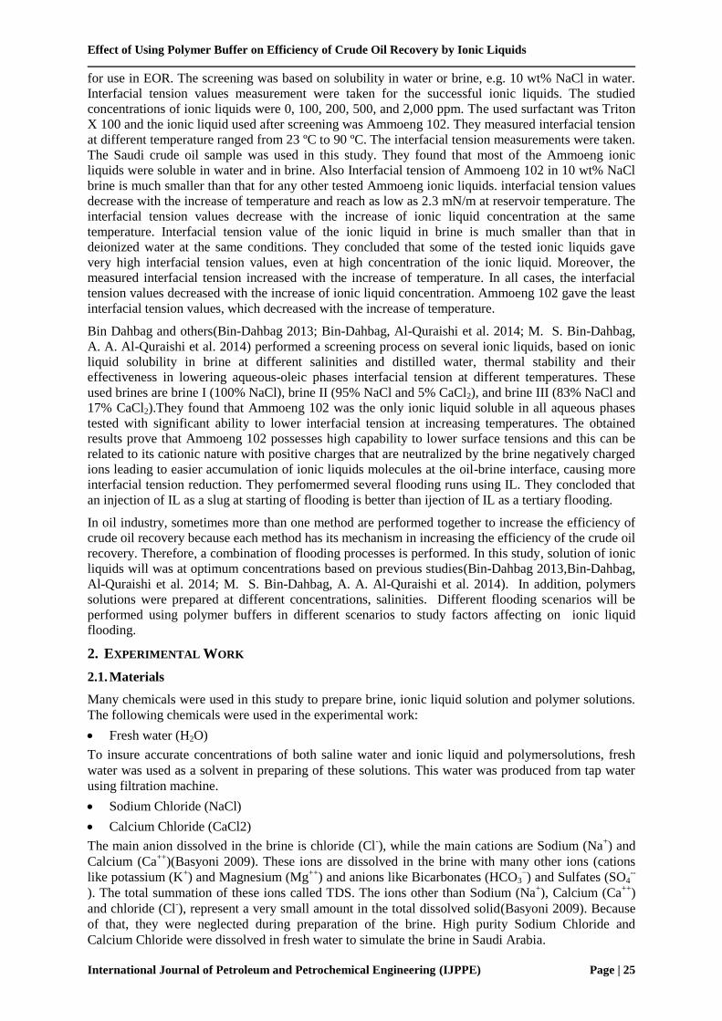
Berea sandstone core samples were used for flooding tests. Table1summarizes rock samples
petrophysical properties.
Table1. Dimensions, weights and petrophysical properties of the used cyliderical core samples.
Run
code
D, cm L,cm VB, cm3 Wd, gm Ws, gm VP, cm
3 φ,% k, md
#3 3.78 11.82 132.65 282.0 311.7 25.77 19.43 233
#9 3.84 10.72 124.15 258.2 285.3 23.51 18.94 221
#10 3.80 10.25 115.89 243.4 269.1 22.30 19.24 216
#11 3.85 11.26 131.03 271.8 301.6 25.86 19.73 202
#12 3.78 11.83 132.76 279.7 310.1 26.38 19.87 210
#13 3.69 12.03 128.60 259.7 287.6 24.21 18.82 211
#14 3.80 11.45 129.52 273.3 301.6 24.56 18.96 209
#15 3.81 11.31 128.61 282.0 311.2 25.34 19.70 212
2.2. Flooding Unit
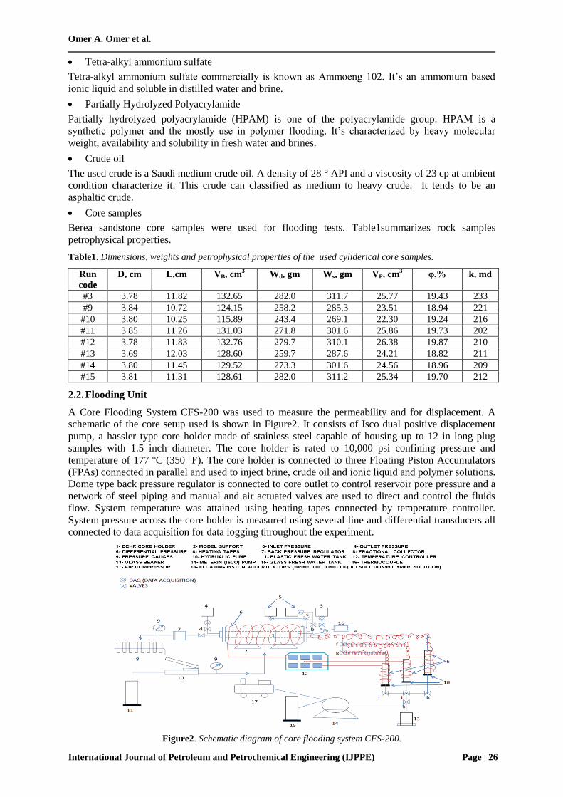
A Core Flooding System CFS-200 was used to measure the permeability and for displacement. A
schematic of the core setup used is shown in Figure2. It consists of Isco dual positive displacement
pump, a hassler type core holder made of stainless steel capable of housing up to 12 in long plug
samples with 1.5 inch diameter. The core holder is rated to 10,000 psi confining pressure and
temperature of 177 ºC (350 ºF). The core holder is connected to three Floating Piston Accumulators
(FPAs) connected in parallel and used to inject brine, crude oil and ionic liquid and polymer solutions.
Dome type back pressure regulator is connected to core outlet to control reservoir pore pressure and a
network of steel piping and manual and air actuated valves are used to direct and control the fluids
flow. System temperature was attained using heating tapes connected by temperature controller.
System pressure across the core holder is measured using several line and differential transducers all
connected to data acquisition for data logging throughout the experiment.
Figure2. Schematic diagram of core flooding system CFS-200.
Effect of Using Polymer Buffer on Efficiency of Crude Oil Recovery by Ionic Liquids
International Journal of Petroleum and Petrochemical Engineering (IJPPE) Page | 27
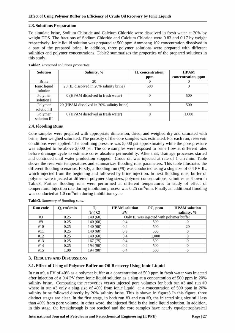
2.3. Solutions Preparation
To simulate brine, Sodium Chloride and Calcium Chloride were dissolved in fresh water at 20% by
weight TDS. The fractions of Sodium Chloride and Calcium Chloride were 0.83 and 0.17 by weight
respectively. Ionic liquid solution was prepared at 500 ppm Ammoeng 102 concentration dissolved in
a part of the prepared brine. In addition, three polymer solutions were prepared with different
salinities and polymer concentrations. Table2 summarizes the properties of the prepared solutions in
this study.
Table2. Prepared solutions properties.
Solution Salinity, % IL concentration,
ppm
HPAM
concentration, ppm
Brine 20 0 0
Ionic liquid
solution
20 (IL dissolved in 20% salinity brine) 500 0
Polymer
solution I
0 (HPAM dissolved in fresh water) 0 500
Polymer
solution II
20 (HPAM dissolved in 20% salinity brine) 0 500
Polymer
solution III
0 (HPAM dissolved in fresh water) 0 1,000
2.4. Flooding Runs
Core samples were prepared with appropriate dimension, dried, and weighed dry and saturated with
brine, then weighed saturated. The porosity of the core samples was estimated. For each run, reservoir
conditions were applied. The confining pressure was 5,000 psi approximately while the pore pressure
was adjusted to be above 2,000 psi. The core samples were exposed to brine flow at different rates
before drainage cycle to estimate cores absolute permeability. After that, drainage processes started
and continued until water production stopped. Crude oil was injected at rate of 1 cm3/min. Table
shows the reservoir temperatures and summarizes flooding runs parameters. This table illustrates the
different flooding scenarios. Firstly, a flooding run (#9) was conducted using a slug size of 0.4 PV IL,
which injected from the beginning and followed by brine injection. In next flooding runs, buffer of
polymer were injected at different polymer slug sizes, polymer concentrations, salinities as shown in
Table3. Further flooding runs were performed at different temperatures to study of effect of
temperature. Injection rate during imbibition process was 0.25 cm3/min. Finally an additional flooding
was conducted at 1.0 cm3/min during imbibition cycle.
Table3. Summery of flooding runs.
Run code Q, cm3/min T,
ºF (ºC)
HPAM solution
PV
PC, ppm HPAM solution
salinity, %
#3 0.25 140 (60) Only IL was injected with polymer buffer
#9 0.25 140 (60) 0.4 500 0
#10 0.25 140 (60) 0.4 500 20
#11 0.25 140 (60) 0.3 500 0
#12 0.25 140 (60) 0.4 1,000 0
#13 0.25 167 (75) 0.4 500 0
#14 0.25 194 (90) 0.4 500 0
#15 1.00 194 (90) 0.4 500 0
3. RESULTS AND DISCUSSIONS
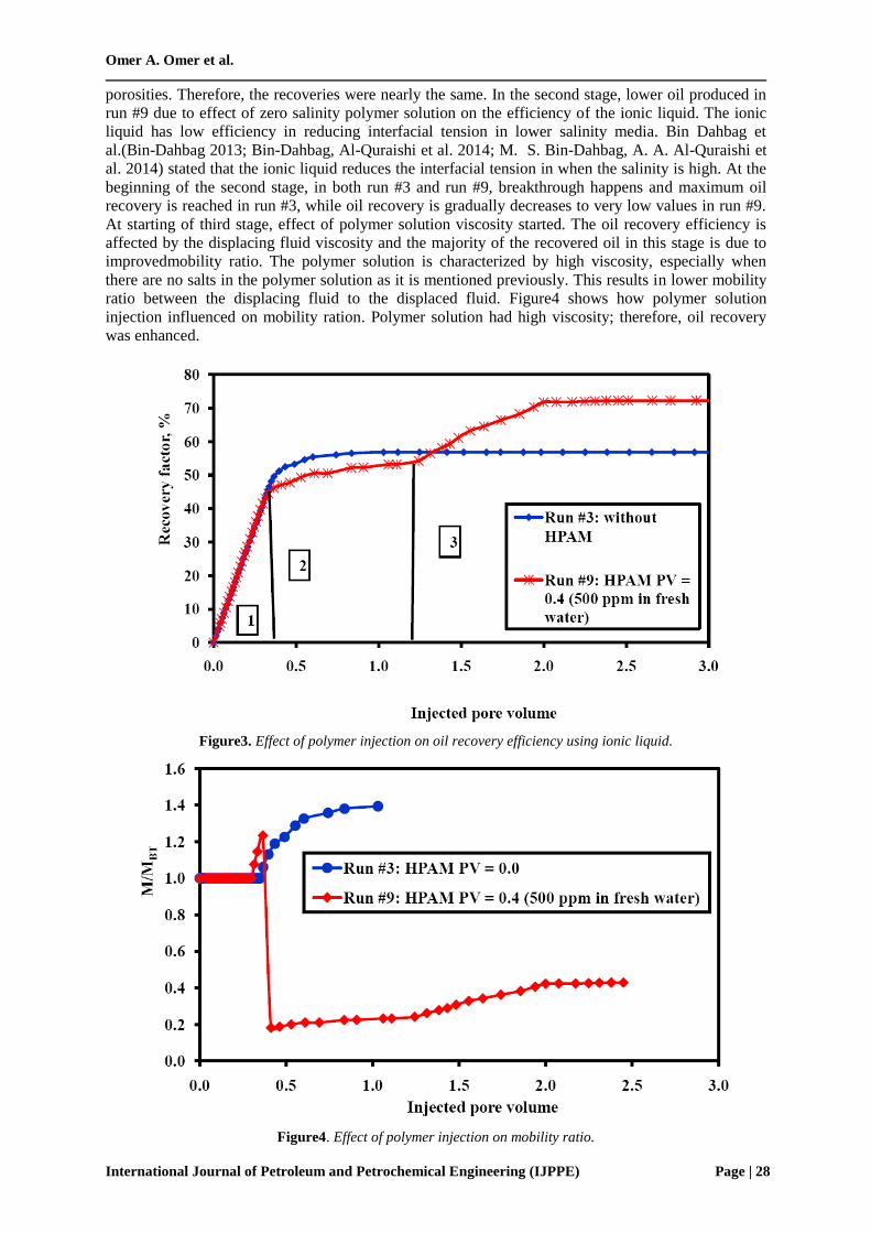
3.1. Effect of Using of Polymer Buffer on Oil Recovery Using Ionic Liquid
In run #9, a PV of 40% as a polymer buffer at a concentration of 500 ppm in fresh water was injected
after injection of a 0.4 PV from ionic liquid solution as a slug at a concentration of 500 ppm in 20%
salinity brine. Comparing the recoveries versus injected pore volumes for both run #3 and run #9
where in run #3 only a slug size of 40% from ionic liquid at a concentration of 500 ppm in 20%
salinity brine followed directly by 20% salinity brine. This is shown in figure3 In this figure, three
distinct stages are clear. In the first stage, in both run #3 and run #9, the injected slug size still less
than 40% from pore volume, in other word, the injected fluid is the ionic liquid solution. In addition,
in this stage, the breakthrough is not reached and the core samples have nearly equalpetrophysical
Omer A. Omer et al.
International Journal of Petroleum and Petrochemical Engineering (IJPPE) Page | 28
porosities. Therefore, the recoveries were nearly the same. In the second stage, lower oil produced in
run #9 due to effect of zero salinity polymer solution on the efficiency of the ionic liquid. The ionic
liquid has low efficiency in reducing interfacial tension in lower salinity media. Bin Dahbag et
al.(Bin-Dahbag 2013; Bin-Dahbag, Al-Quraishi et al. 2014; M. S. Bin-Dahbag, A. A. Al-Quraishi et
al. 2014) stated that the ionic liquid reduces the interfacial tension in when the salinity is high. At the
beginning of the second stage, in both run #3 and run #9, breakthrough happens and maximum oil
recovery is reached in run #3, while oil recovery is gradually decreases to very low values in run #9.
At starting of third stage, effect of polymer solution viscosity started. The oil recovery efficiency is
affected by the displacing fluid viscosity and the majority of the recovered oil in this stage is due to
improvedmobility ratio. The polymer solution is characterized by high viscosity, especially when
there are no salts in the polymer solution as it is mentioned previously. This results in lower mobility
ratio between the displacing fluid to the displaced fluid. Figure4 shows how polymer solution
injection influenced on mobility ration. Polymer solution had high viscosity; therefore, oil recovery
was enhanced.
Figure3. Effect of polymer injection on oil recovery efficiency using ionic liquid.
Figure4. Effect of polymer injection on mobility ratio.
Effect of Using Polymer Buffer on Efficiency of Crude Oil Recovery by Ionic Liquids
International Journal of Petroleum and Petrochemical Engineering (IJPPE) Page | 29
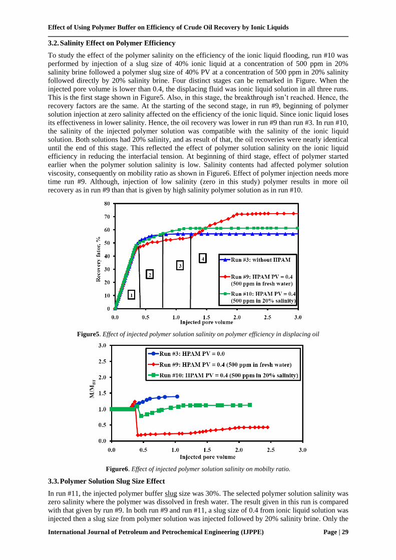
3.2. Salinity Effect on Polymer Efficiency
To study the effect of the polymer salinity on the efficiency of the ionic liquid flooding, run #10 was
performed by injection of a slug size of 40% ionic liquid at a concentration of 500 ppm in 20%
salinity brine followed a polymer slug size of 40% PV at a concentration of 500 ppm in 20% salinity
followed directly by 20% salinity brine. Four distinct stages can be remarked in Figure. When the
injected pore volume is lower than 0.4, the displacing fluid was ionic liquid solution in all three runs.
This is the first stage shown in Figure5. Also, in this stage, the breakthrough isn’t reached. Hence, the
recovery factors are the same. At the starting of the second stage, in run #9, beginning of polymer
solution injection at zero salinity affected on the efficiency of the ionic liquid. Since ionic liquid loses
its effectiveness in lower salinity. Hence, the oil recovery was lower in run #9 than run #3. In run #10,
the salinity of the injected polymer solution was compatible with the salinity of the ionic liquid
solution. Both solutions had 20% salinity, and as result of that, the oil recoveries were nearly identical
until the end of this stage. This reflected the effect of polymer solution salinity on the ionic liquid
efficiency in reducing the interfacial tension. At beginning of third stage, effect of polymer started
earlier when the polymer solution salinity is low. Salinity contents had affected polymer solution
viscosity, consequently on mobility ratio as shown in Figure6. Effect of polymer injection needs more
time run #9. Although, injection of low salinity (zero in this study) polymer results in more oil
recovery as in run #9 than that is given by high salinity polymer solution as in run #10.
Figure5. Effect of injected polymer solution salinity on polymer efficiency in displacing oil
Figure6. Effect of injected polymer solution salinity on mobilty ratio.
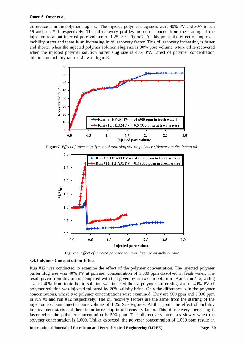
3.3. Polymer Solution Slug Size Effect
In run #11, the injected polymer buffer slug size was 30%. The selected polymer solution salinity was
zero salinity where the polymer was dissolved in fresh water. The result given in this run is compared
with that given by run #9. In both run #9 and run #11, a slug size of 0.4 from ionic liquid solution was
injected then a slug size from polymer solution was injected followed by 20% salinity brine. Only the
Omer A. Omer et al.
International Journal of Petroleum and Petrochemical Engineering (IJPPE) Page | 30
difference is in the polymer slug size. The injected polymer slug sizes were 40% PV and 30% in run
#9 and run #11 respectively. The oil recovery profiles are corresponded from the starting of the
injection to about injected pore volume of 1.25. See Figure7. At this point, the effect of improved
mobility starts and there is an increasing in oil recovery factor. This oil recovery increasing is faster
and shorter when the injected polymer solution slug size is 30% pore volume. More oil is recovered
when the injected polymer solution buffer slug size is 40% PV. Effect of polymer concentration
dilution on mobility ratio is show in figure8.
Figure7. Effect of injected polymer solution slug size on polymer efficiency in displacing oil.
Figure8. Effect of injected polymer solution slug size on mobilty ratio.
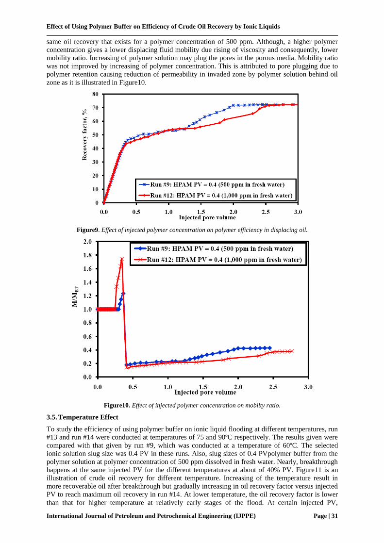
3.4. Polymer Concentration Effect
Run #12 was conducted to examine the effect of the polymer concentration. The injected polymer
buffer slug size was 40% PV at polymer concentration of 1,000 ppm dissolved in fresh water. The
result given from this run is compared with that given by run #9. In both run #9 and run #12, a slug
size of 40% from ionic liquid solution was injected then a polymer buffer slug size of 40% PV of
polymer solution was injected followed by 20% salinity brine. Only the difference is in the polymer
concentrations, where two polymer concentrations were examined. They are 500 ppm and 1,000 ppm
in run #9 and run #12 respectively. The oil recovery factors are the same from the starting of the
injection to about injected pore volume of 1.25. See Figure9. At this point, the effect of mobility
improvement starts and there is an increasing in oil recovery factor. This oil recovery increasing is
faster when the polymer concentration is 500 ppm. The oil recovery increases slowly when the
polymer concentration is 1,000. Unlike expected, the polymer concentration of 1,000 ppm results in
Effect of Using Polymer Buffer on Efficiency of Crude Oil Recovery by Ionic Liquids
International Journal of Petroleum and Petrochemical Engineering (IJPPE) Page | 31
same oil recovery that exists for a polymer concentration of 500 ppm. Although, a higher polymer
concentration gives a lower displacing fluid mobility due rising of viscosity and consequently, lower
mobility ratio. Increasing of polymer solution may plug the pores in the porous media. Mobility ratio
was not improved by increasing of polymer concentration. This is attributed to pore plugging due to
polymer retention causing reduction of permeability in invaded zone by polymer solution behind oil
zone as it is illustrated in Figure10.
Figure9. Effect of injected polymer concentration on polymer efficiency in displacing oil.
Figure10. Effect of injected polymer concentration on mobilty ratio.
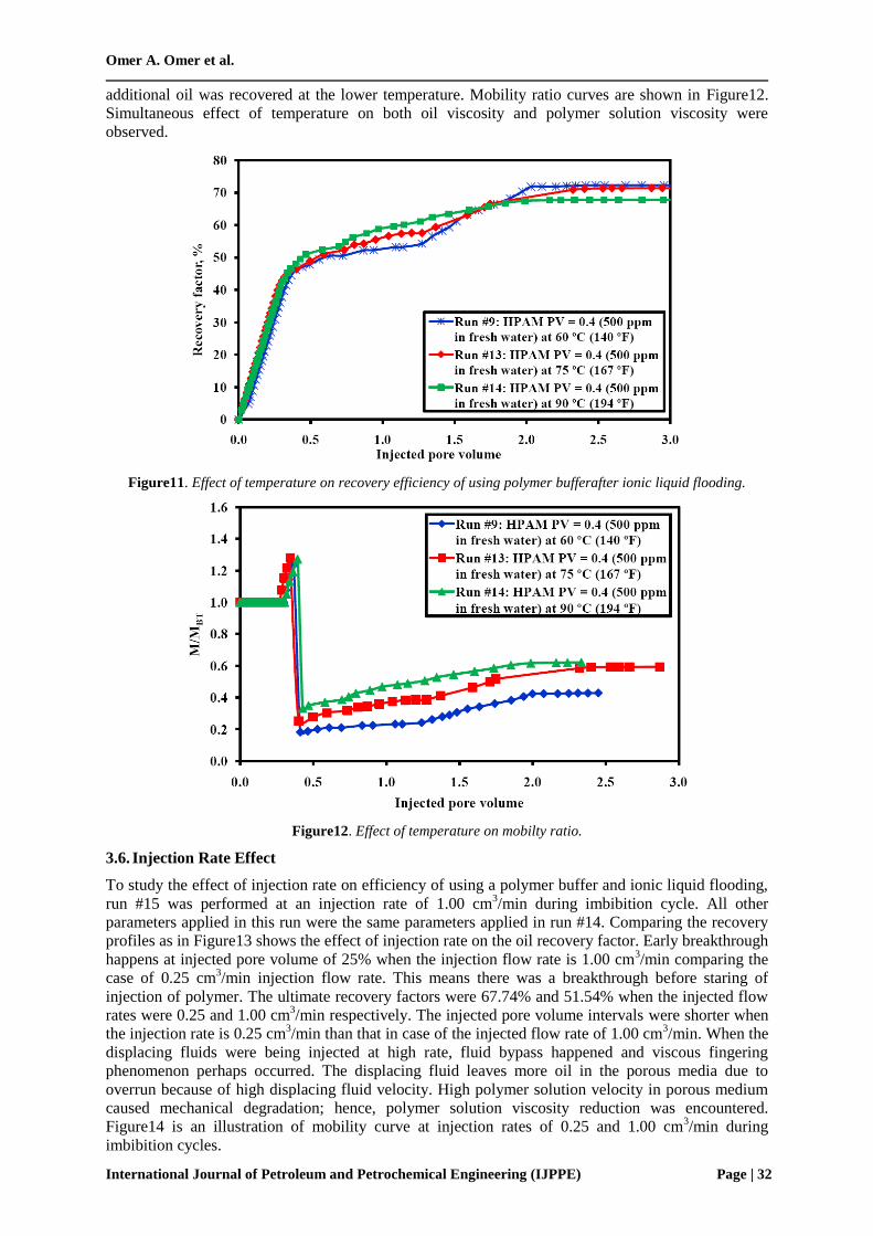
3.5. Temperature Effect
To study the efficiency of using polymer buffer on ionic liquid flooding at different temperatures, run
#13 and run #14 were conducted at temperatures of 75 and 90ºC respectively. The results given were
compared with that given by run #9, which was conducted at a temperature of 60ºC. The selected
ionic solution slug size was 0.4 PV in these runs. Also, slug sizes of 0.4 PVpolymer buffer from the
polymer solution at polymer concentration of 500 ppm dissolved in fresh water. Nearly, breakthrough
happens at the same injected PV for the different temperatures at about of 40% PV. Figure11 is an
illustration of crude oil recovery for different temperature. Increasing of the temperature result in
more recoverable oil after breakthrough but gradually increasing in oil recovery factor versus injected
PV to reach maximum oil recovery in run #14. At lower temperature, the oil recovery factor is lower
than that for higher temperature at relatively early stages of the flood. At certain injected PV,
Omer A. Omer et al.
International Journal of Petroleum and Petrochemical Engineering (IJPPE) Page | 32
additional oil was recovered at the lower temperature. Mobility ratio curves are shown in Figure12.
Simultaneous effect of temperature on both oil viscosity and polymer solution viscosity were
observed.
Figure11. Effect of temperature on recovery efficiency of using polymer bufferafter ionic liquid flooding.
Figure12. Effect of temperature on mobilty ratio.
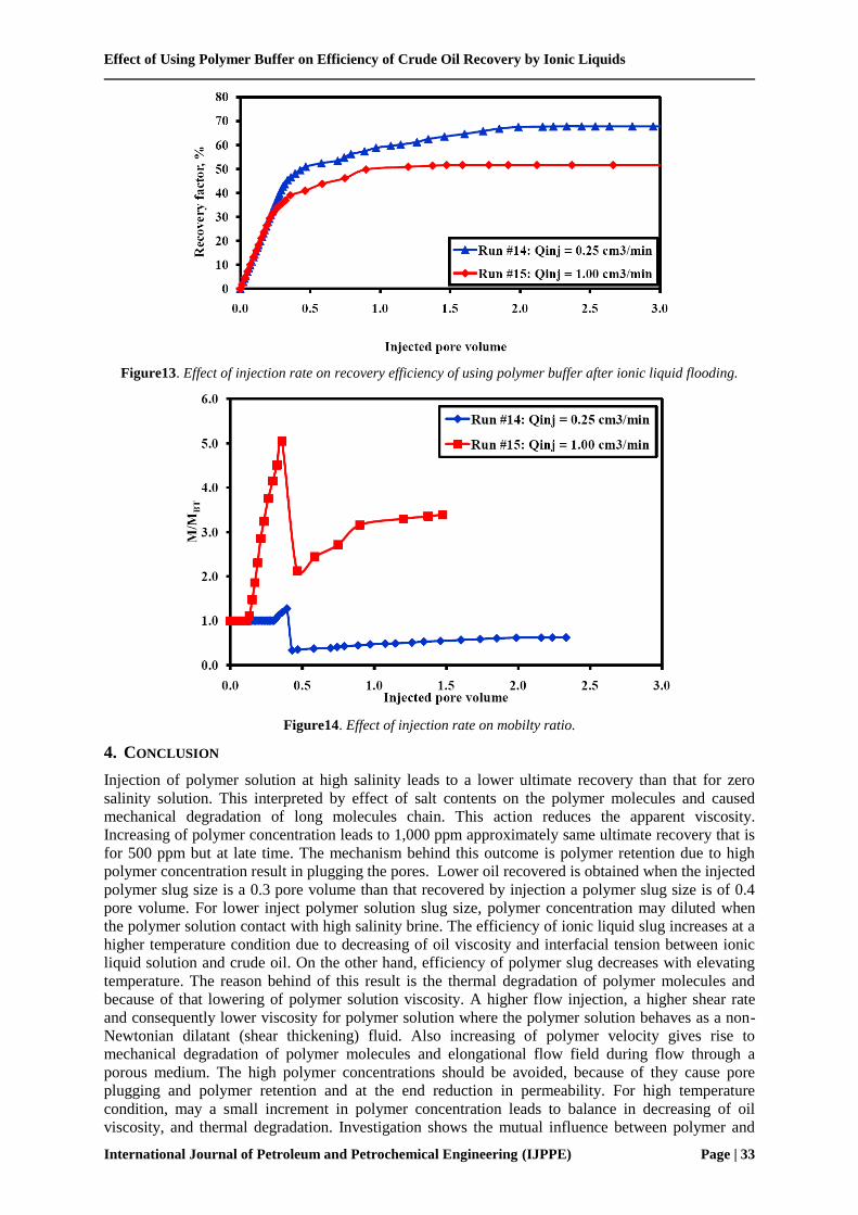
3.6. Injection Rate Effect
To study the effect of injection rate on efficiency of using a polymer buffer and ionic liquid flooding,
run #15 was performed at an injection rate of 1.00 cm3/min during imbibition cycle. All other
parameters applied in this run were the same parameters applied in run #14. Comparing the recovery
profiles as in Figure13 shows the effect of injection rate on the oil recovery factor. Early breakthrough
happens at injected pore volume of 25% when the injection flow rate is 1.00 cm3/min comparing the
case of 0.25 cm3/min injection flow rate. This means there was a breakthrough before staring of
injection of polymer. The ultimate recovery factors were 67.74% and 51.54% when the injected flow
rates were 0.25 and 1.00 cm3/min respectively. The injected pore volume intervals were shorter when
the injection rate is 0.25 cm3/min than that in case of the injected flow rate of 1.00 cm
3/min. When the
displacing fluids were being injected at high rate, fluid bypass happened and viscous fingering
phenomenon perhaps occurred. The displacing fluid leaves more oil in the porous media due to
overrun because of high displacing fluid velocity. High polymer solution velocity in porous medium
caused mechanical degradation; hence, polymer solution viscosity reduction was encountered.
Figure14 is an illustration of mobility curve at injection rates of 0.25 and 1.00 cm3/min during
imbibition cycles.
Effect of Using Polymer Buffer on Efficiency of Crude Oil Recovery by Ionic Liquids
International Journal of Petroleum and Petrochemical Engineering (IJPPE) Page | 33
Figure13. Effect of injection rate on recovery efficiency of using polymer buffer after ionic liquid flooding.
Figure14. Effect of injection rate on mobilty ratio.
4. CONCLUSION
Injection of polymer solution at high salinity leads to a lower ultimate recovery than that for zero
salinity solution. This interpreted by effect of salt contents on the polymer molecules and caused
mechanical degradation of long molecules chain. This action reduces the apparent viscosity.
Increasing of polymer concentration leads to 1,000 ppm approximately same ultimate recovery that is
for 500 ppm but at late time. The mechanism behind this outcome is polymer retention due to high
polymer concentration result in plugging the pores. Lower oil recovered is obtained when the injected
polymer slug size is a 0.3 pore volume than that recovered by injection a polymer slug size is of 0.4
pore volume. For lower inject polymer solution slug size, polymer concentration may diluted when
the polymer solution contact with high salinity brine. The efficiency of ionic liquid slug increases at a
higher temperature condition due to decreasing of oil viscosity and interfacial tension between ionic
liquid solution and crude oil. On the other hand, efficiency of polymer slug decreases with elevating
temperature. The reason behind of this result is the thermal degradation of polymer molecules and
because of that lowering of polymer solution viscosity. A higher flow injection, a higher shear rate
and consequently lower viscosity for polymer solution where the polymer solution behaves as a non-
Newtonian dilatant (shear thickening) fluid. Also increasing of polymer velocity gives rise to
mechanical degradation of polymer molecules and elongational flow field during flow through a
porous medium. The high polymer concentrations should be avoided, because of they cause pore
plugging and polymer retention and at the end reduction in permeability. For high temperature
condition, may a small increment in polymer concentration leads to balance in decreasing of oil
viscosity, and thermal degradation. Investigation shows the mutual influence between polymer and
Omer A. Omer et al.
International Journal of Petroleum and Petrochemical Engineering (IJPPE) Page | 34
ionic liquid solutions using a slug size of law salinity water as a preflush between ionic liquid and
polymer solution. Further experiments may be required to study the effectiveness of polymer-ionic
liquid flooding in carbonate rocks.
ACKNOWLEDGEMENT
The authors would like to thank King Saud University for allowing of use Petroleum and Natural Gas
Department Labs. In addition, thanks go to the department staff. Special thanks go to Mr. Khalid Al-
Khidir for providing us HPAM as a powder.
REFERENCES
[1] Abidin, A., T. Puspasari, et al. (2012). "Polymers for enhanced oil recovery technology."
Procedia Chemistry 4: 11-16.
[2] Alvarado, V. and E. Manrique (2010). "Enhanced oil recovery: an update review." Energies 3(9):
1529-1575.
[3] Aronofsky, J. (1952). "Mobility ratio-Its influence on flood patterns during water encroachment."
Journal of Petroleum Technology 4(01): 15-24.
[4] Aronofsky, J. and H. Ramey Jr (1956). "Mobility Ratio-Its Influence on Injection or Production
Histories in Five-Spot Water Flood." Journal of Petroleum Technology 8(09): 205-210.
[5] Barnes, A. (1962). "The use of a viscous slug to improve waterflood efficiency in a reservoir
partially invaded by bottom water." Journal of Petroleum Technology 14(10): 1,147-141,153.
[6] Basyoni, M. H. (2009). "Sediment characteristics, brine chemistry and evolution of Murayr
sabkha, Arabian (Persian) Gulf, Saudi Arabia."
[7] Benzagouta, M. S., I. M. AlNashef, et al. (2013). "Ionic liquids as novel surfactants for potential
use in enhanced oil recovery." Korean Journal of Chemical Engineering 30(11): 2108-2117
[8] Bin-Dahbag, M. S. (2013). Effect of Ionic Liquids on the Efficiency of Crude Oil Recovery.
master, King Saud University.
[9] Bin-Dahbag, M. S., A. A. Al-Quraishi, et al. (2014). "Efficiency of ionic liquids for chemical
enhanced oil recovery." Journal of Petroleum Exploration and Production Technology: 1-9.
[10] Caudle, B. and M. Witte (1959). "Production potential changes during sweep-out in a five-spot
system." Journal of Petroleum Technology 12(12): 63-65.
[11] collective, A. "Enabling Technologies: Ionic Liquids." Chem.Files vol. 5(6): 23.
[12] Dai, S., D. DePaoli, et al. (2003). "Technical summaries on ionic liquids in chemical
processing." Chemical Industry Vision 2020.
[13] Domańska, U. (2005). "Solubilities and thermophysical properties of ionic liquids." Pure and
applied chemistry 77(3): 543-557.
[14] Dyes, A., B. Caudle, et al. (1954). "Oil production after breakthrough as influenced by mobility
ratio." Journal of Petroleum Technology 6(04): 27-32.
[15] Dykstra, H. and R. Parsons (1950). "The Prediction of Oil Recovery by Water Flood, Secondary
Recovery of Oil in the United States, Principle and Practice." Am. Pet. Inst.
[16] Gao, C. (2013). "Viscosity of partially hydrolyzed polyacrylamide under shearing and heat."
Journal of Petroleum Exploration and Production Technology 3(3): 203-206.
[17] Johnson, K. E. (2007). "What's an ionic liquid?" Interface-Electrochemical Society 16(1): 38-41.
[18] José-Alberto, M.-H. and A. Jorge (2011). "Current knowledge and potential applications of ionic
liquids in the petroleum industry." Ionic liquids: applications and perspectives, InTech: 439-456.
[19] M. S. Bin-Dahbag, A. A. Al-Quraishi, et al. (2014). "Experimental Study of Use of Ionic
Liquids in Enhanced Oil Recovery." J Pet Environ Biotechnol 4(165): 2.
[20] Maerker, J. (1975). "Shear degradation of partially hydrolyzed polyacrylamide solutions."
Society of Petroleum Engineers Journal 15(04): 311-322.
[21] Moffitt, P. and J. Mitchell (1983). North Burbank Unit Commercial Scale Polymerflood Project-
Osage County, Oklahoma. SPE Production Operations Symposium, Society of Petroleum
Engineers.
[22] Mungan, N. (1972). "Shear viscosities of ionic polyacrylamide solutions." Society of Petroleum
Engineers Journal 12(06): 469-473
Effect of Using Polymer Buffer on Efficiency of Crude Oil Recovery by Ionic Liquids
International Journal of Petroleum and Petrochemical Engineering (IJPPE) Page | 35
[23] Muskat, M. (1949). "Physical principles of oil production." McGrawHill Book Co.
[24] Needham, R. B. and P. H. Doe (1987). "Polymer flooding review." Journal of Petroleum
Technology 39(12): 1,503-501,507.
[25] Pye, D. J., W. Gogarthy, et al. (1964). "Improved secondary recovery by control of water
mobility." J. Pet. Technol.;(United States) 16(8).
[26] Ryles, R. (1988). "Chemical stability limits of water-soluble polymers used in oil recovery
processes." SPE reservoir engineering 3(01): 23-34.
[27] Sandiford, B. (1964). "Laboratory and field studies of water floods using polymer solutions to
increase oil recoveries." Journal of Petroleum Technology 16(08): 917-922
[28] Simoni, L. D., Y. Lin, et al. (2008). "Modeling liquid-liquid equilibrium of ionic liquid systems
with NRTL, electrolyte-NRTL, and UNIQUAC." Industrial & Engineering Chemistry Research
47(1): 256-272.
[29] Sorbie, K. S. (1991). "Polymer-Improved Oil Recovery." Glasgow and London, Blackie.
[30] Stiles, W. E. (1949). "Use of permeability distribution in water flood calculations." Journal of
Petroleum Technology 1(01): 9-13.
[31] Ward, J. and F. D. Martin (1981). "Prediction of viscosity for partially hydrolyzed
polyacrylamide solutions in the presence of calcium and magnesium ions." Society of Petroleum
Engineers Journal 21(05): 623-631