Embed Size (px)
Citation preview

Journal of Materials Science and Engineering A 6 (7-8) (2016) 213-221 doi: 10.17265/2161-6213/2016.7-8.004
Effect of Water Content in the Gas Diffusion Layer of
H2/O2 PEM Fuel Cell
German Cespedes1, Mariano Asteazaran2 and Ana M. Castro Luna1, 2*
1. Centro de Investigación y Desarrollo en Ciencia y Tecnología de Materiales(CITEMA), Facultad Regional La Plata, Universidad
Tecnológica Nacional, La Plata, 1900, Argentina
2. Instituto de Investigaciones Fisicoquímicas Teóricas y Aplicadas (INIFTA), Facultad de Ciencias Exactas, UNLP-CONICET, La
Plata, 1900, Argentina
Abstract: The heart of a fuel cell is the membrane-electrode assembly consisting of two porous electrodes, where the electrochemical reactions take place, and the ionomer conductive membrane, which allows the proton exchange from the anode to the cathode. The porosity of the electrodes plays an important role in the fuel cell performance. One of the drawbacks presented by the porous electrodes is the accumulation of water in their structure, which implies a hindrance for the reactive gas transport to reach the catalytic reactive sites. In this paper, a mathematical model of a porous electrode, assuming single pores with uniform distribution, is introduced to determine the influence of water accumulation in the electrode on the fuel cell performance under different operating conditions. It is demonstrated that at low current densities, water accumulation has no effect in the fuel cell behavior, whereas at high current densities its performance is severely affected. Key words: Fuel cells, porous-electrodes, electrode flooding.
Nomenclature
A Electrode area (cm2)
C Concentration (mol·cm-3)
F Faraday Constant (96487 C)
i Current density (A·cm-2)
i0 Exchange current density (A·cm-2)
iL Limit current density (A·cm-2)
M- Anode water balance (mol·s-1)
M+ Cathode water balance (mol·s-1)
Mmax Water amount to complete flooding (mol·s-1)
p Total pressure (atm)
2Hp H2 pressure (atm)
pgas Air pressure (atm)
R Ideal gas constant (8.3142 J·mol-1·K-1)
T Temperature (K)
E Operation voltage (V)
ENernst Nernst operation voltage (V)
Wtr-EOD Water transport through the membrane (mol·cm-2·s-1)
Whum Water inlet to the cell due to reactant gas humidity (mol·cm-2·s-1)
Wgen Water production at the cathode (mol·cm-2·s-1)
*Corresponding author: Ana M. Castro Luna, Ph.D., professor, research fields: fuel cells and electrochemistry.
Wout Water exit from the cell (mol·cm-2·s-1)
x Molar fraction
2H Oa Water activity
xhum Molar fraction corresponding to humidification condition
VOhm Ohmic loss (V)
Greek letters
σ Membrane ionic conductivity (S·cm-2)
δ Membrane thickness (cm)
ηact Activation overpotential (V)
Activation overpotential corresponding to hydrogen oxidation reaction (V)
Activation overpotential corresponding to oxygen reduction reaction (V)
Concentration overpotential (V)
ρ Density
ζ Stoichiometry coefficient
α Charge transfer coefficient
Є0 Initial electrode porosity
Єhum Porosity corresponding to humidification condition
λ Water content or local ratio H2O/SO3
- in the membrane
ηdrag Electro-osmotic drag coefficient
D DAVID PUBLISHING

Effect of Water Content in the Gas Diffusion Layer of H2/O2 PEM Fuel Cell
214
1. Introduction
Fuel cells are electrical power sources on which the
chemical energy contained in a compound as
hydrogen is spontaneously converted into electricity.
The process is cleaner and more efficient than that
based on burning fossil fuels, which is seriously
harmful to the environment. As long as the reactant
and oxidant are supplied, fuel cells can provide
electricity and reach high efficiency, because they
involve a single transformation step and unlike
conventional heat engines, they are not under Carnot
limitation.
Polymer electrolyte membrane fuel cells (PEMFCs)
are very attractive as power sources in portable,
transport and stationary applications, because they can
deliver high power density at low temperatures, are
noiseless and lightweight, have low maintenance and
have no mechanical components. They are also
friendly to the environment.
Nafion® membrane is usually employed in
PEMFCs as ionomeric electrolyte, which is a
peruorsulfonic acid membrane consisting of a
hydrophobic polytetrauoroethylene backbone
functionalized with hydrophilic sulfonic-acid at the
end of lateral chains. The content of water in the
membrane affects its ionic conductivity, because
proton migration occurs in the ionomeric hydrated
phase with participation of dissociated sulfonic groups
[1-3]. In the search of highly efficient and reliable
PEMFCs, considerable work has been done. Many
internal and external factors affect their performance,
such as catalytic performance, complex reaction
pathways, materials degradation, mass transport, fuel
cell design and assembly, operational conditions.
[4-8].
A model of the processes taking place inside the
fuel cells could help to understand what is the most
important factors to improve and optimize its
performance. Due to the complexity of the
processes in real cells, one dimension and constant
temperature are assumed, in most of the previously
studied models [9-13]. In general, the models are able
to give reasonable predictions of the cell performance
in the low and intermediate current density ranges, but
failed to reproduce the experimental curves at high
current densities, where an abrupt potential drop is
observed.
Some authors consider that the electrode porosity
does not change during cell operation; however, it is
well known that it can be affected by many factors
when current is drained. One of the most significant
factors is water accumulation in the electrode porous
layer, which can provoke flooding, a non-uniform
pore distribution and an increase in the reactant
transport resistance [14].
The aim of this work is to evaluate the role of the
relative humidity of the reactive gases needed to avoid
the accumulation of water in the porous electrode. A
simplified model which considers a H2/O2 PEMFC
operating under steady state conditions at constant
temperature with a single pore distribution is
introduced and discussed.
2. Mathematical Model
The model to be considered takes the following
premises into account:
The reactant concentration of both gases (H2/O2) is
constant.
The fuel cell work under isothermal conditions.
The potential at the membrane electrode interface is
constant.
The pressure of gases and fluids is constant.
There are no changes in the material properties in
20-90 ºC temperature range.
An ideal behavior of gases and fluids is considered.
A uniform pore distribution in the electrode is
assumed.
The proton exchange membrane is always
completely hydrated.
2.1 Description of the Fuel Cell
Typically, each individual PEMFC is made of a

Effect of Water Content in the Gas Diffusion Layer of H2/O2 PEM Fuel Cell
215
layered structure consisting of an
electrode-membrane-electrode assembly (MEA),
which is constrained among two flow field plates,
which plays two roles i) by collecting the current and
ii) by supplying the reactants through the gas diffusion
layer (GDL) to the catalytic active sites. The MEA
comprises two electrodes separated by a thin Nafion®
membrane (Fig. 1).
The electrodes are composed of two layers, the gas
diffusion layer (GDL) and the catalytic layer (CL).
The CL is the site where the electrochemical reaction
takes place, whereas the GDL supplies the reactants
(which run through the flow channels of the flow field
plates) and it also drains the products from the CL
(heat, water and electrons). The GDL needs to be
efficient for the gas transporting from the gas flow
channels to the electrolyte/electrode interface [15]. To
achieve the goal it is necessary to maintain free void
pores to ease the diffusive flow of the gases. It is well
known that preventing water away from condensing in
the pores and consequently from obstructing the gas
pathway; the GDL material must be hydrophobic.
Teflon treatments of the GDL reduce the amount of
water in the pores facilitating the gas transport toward
the catalytic sites.
It is important to stress that the GDL plays an
essential role in regulating the flow of water away
from the catalyst layer in PEM fuel cells. However, at
higher current densities, the produced liquid water has
to be removed with the effluent through the gas flow
channels.
Some models assumed that water and gas move
through separate pores. Some authors claimed that a
distribution of pore sizes must be determined to
follow the behavior of the GDL, closely. Thus
Benziger et al. [16] suggest that water move through
large pores and the small pores are kept free of liquid
water.
During fuel cell operation (Fig. 2), H2 reaches, by
diffusion through the porous electrode, the anode
reaction sites of the catalysts and the hydrogen
oxidation reaction (HOR) (as shown in Eq. (1)) takes
place.
2 2 2 H H e (1)
At the cathode, the oxygen reduction reaction
(ORR) with protons and electrons takes place.
2 21 2 22
O H e H O (2)
Consequently, the global fuel cell reaction is:
2 2 212
H O H O (3)
2.2 Water Accumulation in the Porous Electrodes
The water balance in the porous electrode (Fig. 3)
results from the correlation between: i) the water inlet
from the humidified reactant gases, ii) the water
produced according to Eq. (2), iii) the internal water
transport through the membrane between anode and
cathode and iv) the water outlet from the humidified
gases which have not reacted [17].
Fig. 1 Membrane-electrode assembly (MEA).
Fig. 2 Schematic drawing of a H2/O2 fuel cell and the reactions involved in a PEMFC.

Effect of Water Content in the Gas Diffusion Layer of H2/O2 PEM Fuel Cell
216
Fig. 3 Water transport in a typical PEM fuel cell.
The inner water transport through the membrane
results from many contributions; among the most
important, it can be mentioned:
The electro-osmotic drag (EOD) associated to
proton migration, which can be characterized by the
electro-osmotic drag coefficient described by the
number of water molecules moving with each proton
[11].
The back-diffusion due to the water
concentration gradient between cathode and anode.
The thermal osmotic drag (TOD) caused by
differences in temperature along the membrane.
The hydraulic permeation due to different
pressures on each side of the membrane.
The model is developed considering that i) the fuel
cell is working in an isothermal condition, ii) the
water amount in the membrane is constant, iii) no
pressure gradient is applied, consequently, the thermal
osmotic drag, the hydraulic permeation and the back
diffusion caused by concentration gradient can be
neglected.
2.3 Water Inlet
Relative humidity is defined as the ratio of the
actual water vapor pressure to the saturation water
pressure, usually expressed in percentage. A given
amount of water coming with the reactant gases (H2,
air/O2) is taken into account in line with Eqs. (4) and
(5) [10].
2 1
humhum
hum
xiWF x
(4)
2
2
0
0(1 )4 1
humNhum
humO
xxiWF x x
(5)
2.4 Water Produced
A given amount of water is obtained from the ORR
and can be taken into account according to:
2geniWF
(6)
2.5 Water Outlet
A certain amount of the reactive gases are not able
to react in the PEMFC and they exit taking a certain
amount o
electrochem
2.6 Water
Membrane
The elec
protons tran
PEMFC. Sp
water molec
Being the
2.7 Cathodic
According
in each comp
In the fo
porosity in t
3. Effect PEMFC P
The fuel c
value of 1
activity or
equal 1 and
activity of th
1, the cell p
Nernst, equa
lower than 1
Effec
f extra w
mical reaction.
outW
out+ =
4iWF
Transport
ctro-osmotic
nsport from th
pringer et al
cules for each
dra
e dragged wat
tr EW
c and Anodic
g to the mas
partment the
hM W
humM W
ollowing equ
the cathode is
0(1humЄ Є
of WaterPerformanc
cell fed with
.229 V at s
concentratio
d generation
he reactive an
potential shou
ation and the
1.229 V.
ct of Water Co
water prod
.
( 1)2 1
xiF
2
2
0N0O
+ (1+ ) -x
x
through
drag is as
he anode to th
. [11] define
h transported p
2.5=22ag
ter amount:
EOD dragiF
c Water Balan
s balance exp
total amount
umtr EODW
gen tr EOW W
uation, the v
s expressed as
max
1 ),M
if MM
r Accumuce
H2 and O2 ha
standard con
on of reactan
of liquid w
nd products a
uld be correc
e cell potentia
ontent in the
duced by
outw
outw
x
x
+
+
outw
outw
-11-
x
x
the Polym
ssociated to
he cathode in
e the numbe
proton as:
nce
pressed in m
t of water resu
outW
outOD W
variation of
s:
max 1M
lation in
as a cell poten
nditions (25
nts and pro
water). When
are different f
cted accordin
al value beco
Gas Diffusio
the
(7)
(8)
meric
the
n the
er of
(9)
(10)
moles
ults:
(11)
(12)
the
(13)
the
ntial
ºC,
duct
n the
from
ng to
omes
T
mea
volt
curv
dep
pote
the
can
thre
curr
reac
mid
attr
hyd
Fin
in th
nam
T
loss
3.1
T
of
elec
cell
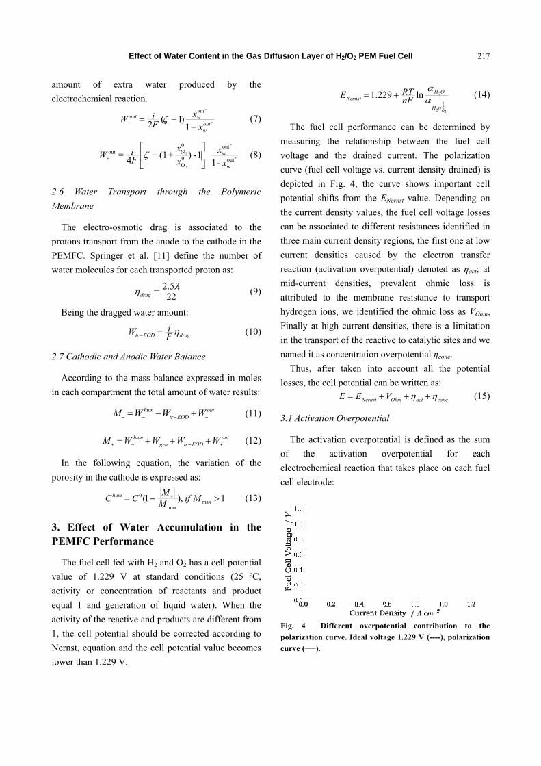
Fig.polacurv
on Layer of H2
E
The fuel cell
asuring the
tage and th
ve (fuel cell
picted in Fig
ential shifts
current dens
n be associate
ee main curre
rent densitie
ction (activat
d-current de
ibuted to th
drogen ions, w
ally at high
he transport o
med it as conc
Thus, after t
ses, the cell p
E
Activation O
The activation
the acti
ctrochemical
l electrode:
. 4 Differearization curveve (____).
2/O2 PEM Fue
1.229NernstE
l performanc
relationship
e drained c
voltage vs. c
g. 4, the cur
from the ENe
sity values, th
ed to differen
ent density re
es caused b
tion overpote
ensities, pre
he membrane
we identified
current densi
of the reactiv
centration ove
taken into a
potential can b
Nernst OE E V
Overpotential
n overpotent
ivation ov
reaction that
ent overpotene. Ideal voltag
el Cell
2
2
9 ln H
H
RTnF
ce can be de
between th
current. The
current densit
rve shows im
Nernst value. D
he fuel cell v
nt resistances
gions, the fir
by the elect
ential) denote
evalent ohm
e resistance
d the ohmic l
ities, there is
ve to catalytic
erpotential ηc
account all t
be written as:
Ohm act coV
ial is defined
erpotential
t takes place
ntial contribue 1.229 V (----
217
2
122O
O
(14)
etermined by
he fuel cell
polarization
ty drained) is
mportant cell
Depending on
voltage losses
identified in
rst one at low
tron transfer
ed as ηact; at
mic loss is
to transport
loss as VOhm,
s a limitation
c sites and we
conc.
the potential
:
onc (15)
d as the sum
for each
on each fuel
ution to the-), polarization
7
)
y
l
n
s
l
n
s
n
w
r
t
s
t
,
n
e
l
)
m
h
l
e n

218
The HOR
opposite oc
catalytic rea
be neglected
The activ
to only ORR
expressed a
equation as
3.2 Ohmic L
Ohmic lo
hydrogen i
employing th
The ohm
conductivity
3.3. Concen
The conc
the reactant
polarization
noticed at hi
where,
When liq
reactant tran
the catalyst
reduces the p
Effec
act
R on Pt is a
ccurs with t
action [18].
d. Then:
ation overpot
R, its relatio
according to
[19]:
act
Losses
oss related
ions transpo
he Ohm law.
ohmV
mic resistance
y and thicknes
OhmR
tration Overp
entration ove
t cannot reac
curve, the
igh current de
concRn
1Li nF
h
quid water ac
nsport through
layer is hin
power output
ct of Water Co
HOR ORRact act
a fast reacti
the ORR, w
Consequently
HORact act
tential is wri
on with the c
o the classic
0
ln i RTi F
to membran
ort can be
OhmiR
e depends on
ss [20, 21] ex
thickm
potential
erpotential is
ch the cataly
mass transp
ensities value
ln L
L
iRTnF i i
0
12
1
hum
mg
C
h D Є
ccumulates i
hout the flow
ndered and,
t from the fue
ontent in the
ion, whereas
which is a s
y the HORact
tten with reg
current densit
c Butler-Vol
ne resistance
e described
n the memb
xpressed as:
s caused bec
ytic sites. In
port influenc
es [22-24].
m
in the GDL,
w-field channe
consequently
el cell. The liq
Gas Diffusio
(16)
the
slow
can
(17)
gards
ty is
lmer
(18)
e to
by
(19)
rane
(20)
ause
n the
ce is
(21)
(22)
the
el to
y, it
quid
wat
whe
elec
den
gett
mas
curr
wat
inte
4. R
T
obta
in
exp
obta
H2
pres
curr
the
S
sho
the
The
for
ana
fuel
wat
loss
to w
Fig.70Sim
on Layer of H2
ter accumulat
ere water is
ctrolyte/electr
nsities water
ting the ele
ss transport r
rent density d
ter to be rem
erface withou
Results and
The values o
ained after re
Eq. (15) are
perimental cu
ained by Mag
and O2 flux,
ssure = 3 atm
rent density-c
experimental
Simulated po
wn in Figs. 6
relative hum
e values of th
calculations
alysis of the c
l cell perform
ter content in
s at high h
water accumu
. 5 PolarizatiºC: experime
mulated data fro
2/O2 PEM Fue
tion is especi
formed in t
rode interfa
accumulatio
ectrode/electr
restrictions w
drained. The
moved from
ut hindering g
d Discussio
of current de
eplacement o
e depicted a
urrent density
ggio et al [25
, cathode fee
m, T = 343.15
cell potential
l data accordi
olarization cu
6 and 7, demo
midity conten
he most signi
s are shown
curves it can b
mance is pos
n the inlet a
humidity valu
ulation in the
ion curve of aental data of om Eq. (15) (-■
el Cell
ially severe a
the catalytic
ace. At h
on avoids o
rolyte interf
which limits th
ideal GDL s
the electrod
gas transport.
n
ensity and c
f Eqs. (18), (
and superimp
y vs. cell pot
] by using a P
ed gas = Air,
5 K. The sim
shows an agr
ing to Fig. 5.
urves and p
onstrate the im
nt in the inle
ificant param
n in Table 1
be concluded
ssible with re
air. The cell
ues could b
e pores of the
a H2/O2 fuel ceMaggio et a■-).
at the cathode
layer at the
high current
oxygen from
face causing
he maximum
hould permit
de/electrolyte
cell potential
(19) and (21)
posed to the
tential values
PEMFC with
cathode gas
mulated curve
reement with
ower curves
mportance of
et air/O2 gas.
meters needed
1. From the
d that a better
elatively low
performance
be attributed
e GDL which
ell working atal. [25] (-►-).
e
e
t
m
g
m
t
e
l
)
e
s
h
s
e
h
s
f
.
d
e
r
w
e
d
h
t .

Fig. 6 Polarrelative humiRH = 40% Polarization region betwee
Fig. 7 Powrelative humi40% (-►-), R
Table 1 Inp
Datum
Cell temperat
Cathode feed
Thickness of
Pressure of th
Ideal gas con
Faraday cons
Initial electro
Cathode stoic
Molar fractio
prevents the
In Fig. 8,
the current
humidifities
inside of th
gas is increa
resulting in f
Effec
rization curveidity in air: RH(-►-), RH =curves magni
en 0.65 and 0.8
wer curve of aidity: RH = 20
RH = 50% (-●-)
put data requir
ture (K)
d gas
the Nafion® me
he gas inlet (H2
stant (J·mol-1·K
tant (C·mol-1)
ode porosity
chiometry coeff
n of O2 in air
gas from rea
changes in t
density dra
, is shown.
e pore when
ased (as happ
fewer pores av
ct of Water Co
s of H2/O2 fuH = 20% (-◄-)
= 50% (-●-), ification in th85 A·cm-2.
a H2/O2 Fuel% (-◄-), RH =), RH = 60% (-
red for calculat
embrane (µm)
and Air) (atm)
K-1)
ficient
aching the cat
the porosity o
ained and d
Water can
n the relative
pens at high c
vailable for ga
ontent in the
el cell at diffe), RH = 30% (RH = 60% (
he current de
Cell at diffe= 30% (-�-), R-■-).
tions.
Value
343.15
Air
183
3
8.31434
96,485.33
0.74
3
0.21
talytic sites.
of the GDL w
different rela
coalesce in
humidity of
current densit
as ux. This bri
Gas Diffusio
erent (-�-), (-■-). nsity
erent RH =
with
ative
the
f the
ties),
ings
Fig.accuin th
Fig.rela
abo
perf
rela
dec
den
F
dep
to p
gas
den
B
the
perf
perc
5. C
T
nec
on Layer of H2
. 8 Changes umulation cauhe inlet gas (ai
. 9 Changes ative humidity
out mass trans
formance of
ative humidit
rease in the
nsity drained i
Fig. 9 depicts
pendence on t
predict the m
inlet to av
nsity drained.
Both Figs. 8 a
water conten
formance, th
centage, the l
Conclusion
To achieve a
essary to det
2/O2 PEM Fue
in the electrused by differer/O2) and the c
in the limitinof the inlet gas
sport limitati
f the fuel ce
ty values hig
porosity av
is higher.
s the limitin
the air relativ
maximum allo
void affecting
and 9 draw at
nt in the por
hus, the high
lower the por
ns
an optimal PE
ermine the m
el Cell
rode porosity ent relative hucurrent densiti
ng current dens (air/O2).
ions and a de
ell. It is noti
gher than 30%
ailable when
g current de
ve humidity:
owed water c
g the maxim
ttention to the
rous electrode
her the relati
re accessibilit
EMFC perfo
maximum wat
219
due to waterumidity valuesies drained.
nsity with the
ecrease in the
iced that for
% there is a
n the current
nsity and its
it is possible
ontent in the
mum current
e influence of
e on the cell
ive humidity
ty.
ormance it is
ter content in
9
r s
e
e
r
a
t
s
e
e
t
f
l
y
s
n

Effect of Water Content in the Gas Diffusion Layer of H2/O2 PEM Fuel Cell
220
the cathode gas inlet in order to avoid flooding during
fuel cell operation. A theoretical approach of how
PEMFC works is proposed. Of the many parameters
that play a part in improving the PEMFC behavior, the
water content in the gas that fed the cathode is
systematically studied in reference to PMFC
performance by using a simple pore approach of the
GDL.
A model is presented and discussed in which
PEMFC operating under steady state and isothermal
conditions together with a simple and uniform porous
electrode structure, is assumed. From the current
potential relationship obtained, it is concluded that for
relative humidity values in the air higher than 30%,
the fuel cell performance starts to decay. The losses in
efficiency are ascribed to the partial flooding of the
porous structure of GDL, which is more severe at
higher current densities.
Acknowledgments
Thisworkwassupportedby Consejo Nacional de
Investigaciones Científicas y Técnicas (CONICET),
Comisión de Investigaciones Científicas de la
Provincia de Buenos Aires (CIC), and Universidad
Tecnológica Nacional (UTN-FRLP). AMCL is
member of the research career at CIC. GC and MA
acknowledge financial support through a Ph.D.
fellowship from CIC and CONICET, respectively.
References
[1] Duan, Q., Wang, H. and Benziger, J. 2012. “Transport of Liquid Water through Nafion Membranes.” Journal of Membrane Science 392-393: 88-94.
[2] Kyu, D., Jung, E., Ho, H. and Soo, M. 2016. “Experimental and Numerical Study on the Water Transport Behavior through Nafion 117 for Polymer Electrolyte Membrane Fuel Cell.” Journal of Membrane Science 497: 194-208.
[3] Ye, X. and Wang, C.-Y. 2007. “Measurement of Water Transport Properties Through Membrane-Electrode Assemblies.” Journal of The Electrochemical Society 154 (7): B676.
[4] Asteazaran, M., Cespedes, G., Moreno, M., Bengió, S. and Castro Luna, A. 2015. “Searching for Suitable
Catalysts for a Passive Direct Methanol Fuel Cell Cathode.” International Journal of Hydrogen Energy 40 (42): 14632-9.
[5] Antolini, E., Salgado, J. R. and Gonzalez, E. R. 2006. “The Stability of PtM (M=first row transition metal) Alloy Catalysts and its Effect on the Activity in Low Temperature Fuel Cells.” Journal of Power Sources 160 (2): 957-68.
[6] Buchi, F. N., Inaba, M. and Schmidt, T. J. 2009. “Polymer Electrolyte” Fuel Cell Durability, vol. 1, doi:10.1007/978-0-387-85536-3.
[7] Tang, H., Wang, S., Jiang, S. P. and Pan, M. 2007. “A Comparative Study of CCM and Hot-Pressed MEAs for PEM Fuel Cells.” Journal of Power Sources 170 (1): 140-4.
[8] Prasanna, M., Cho, E., Lim, T.-H. and Oh, I.-H. 2008. “Effects of MEA Fabrication Method on Durability of Polymer Electrolyte Membrane Fuel Cells.” Electrochimica Acta 53 (16): 5434-41.
[9] Sukkee Um, K. S. C., Wang, C. Y., Um, S., C. Wang, Y., Chen, K. S. and Urn, S. et al. 2000. “Computational Fluid Dynamics Modeling of Proton Exchange Membrane Fuel Cells.” Jounal of Electrochemical Society 147 (12): 4485.
[10] Roshandel, R., Farhanieh, B. and Saievar-Iranizad, E. 2005. “The Effects of Porosity Distribution Variation on PEM Fuel Cell Performance.” Renewable Energy 30 (10): 1557-72.
[11] Springer, T. E., Zawodzinski T. A. and Gottesfeld, S. 1993. “Polymer Electrolyte Fuel Cell Model.” Journal of Electroanalytical Chemistry 138 (8): 2334-42.
[12] Bernardi, D. M. 1992. “A Mathematical Model of the Solid-Polymer-Electrolyte Fuel Cell.” Journal of The Electrochemical Society 139 (9): 2477.
[13] Nitta, I., Himanen, O. and Mikkola, M. 2008. “Thermal Conductivity and Contact Resistance of Compressed Gas Diffusion Layer of PEM Fuel Cell.” Fuel Cells 8 (2): 111-9.
[14] Chu, H. S., Yeh, C. and Chen, F. 2003. “Effects of Porosity Change of Gas Diffuser on Performance of Proton Exchange Membrane Fuel Cell.” Journal of Power Sources 123 (1): 1-9.
[15] Banerjee, R. and Kandlikar, S. G. 2014. “Liquid Water Quantification in the Cathode Side Gas Channels of a Proton Exchange Membrane Fuel Cell through Two-Phase Flow Visualization.” Journal of Power Sources 247: 9-19.
[16] Benziger, J., Nehlsen, J., Blackwell, D., Brennan, T. and Itescu, J. 2005. “Water Flow in the Gas Diffusion Layer of PEM Fuel Cells.” Journal of Membrane Science 261 (1-2): 98-106.
[17] Dai, W., Wang, H., Yuan, X.-Z., Martin, J. J., Yang, D.

Effect of Water Content in the Gas Diffusion Layer of H2/O2 PEM Fuel Cell
221
and Qiao, J. et al. 2009. “A Review on Water Balance in the Membrane Electrode Assembly of Proton Exchange Membrane Fuel Cells.” International Journal of Hydrogen Energy 34 (23): 9461-78.
[18] Kunusch, C., Puleston, P. and Mayosky, M. 2012. Sliding-Mode Control of PEM Fuel Cells. London: Springer. 13-33.
[19] Santarelli, M. G., Torchio, M. F. and Cochis, P. 2006. “Parameters Estimation of a PEM Fuel Cell Polarization Curve and Analysis of their Behavior with Temperature.” Journal of Power Sources 159 (2): 824-35.
[20] Kunusch, C., Puleston, P. F., Mayosky, M. A. and More, J. J. 2010. “Characterization and Experimental Results in PEM Fuel Cell Electrical Behavior.” International Journal of Hydrogen Energy 35 (11): 5876-81.
[21] Nguyen, T. V. 1993. “A Water and Heat Management Model for Proton Exchange-Membrane Fuel Cells” Journal of The Electrochemical Society 140 (8): 2178.
[22] Abderezzak, B., Khelidj, B. and Abbes, M. T. 2014. “Performances Prediction Study for Proton Exchange Membrane Fuel Cells.” International Journal of Hydrogen Energy 39 (27): 15206-14.
[23] Haji, S. 2011. “Analytical Modeling of PEM Fuel Cell i-V Curve.” Renewable Energy 36 (2): 451-8.
[24] Frca, A. C. and Dobra, P. 2014. “Adaptive Control of Membrane Conductivity of PEM Fuel Cell.” Procedia Technology 12: 42-9.
[25] Maggio, L. P. G. and Recupero, V. 2001. “Modeling Polymer Electrolyte Fuel Cells: An Innovative Approach.” Journal of Power Sources 101: 275-86.