Embed Size (px)
Citation preview
Prefeasibility Report for Biomass Based Renewable Fuel Plant at Bhikhpur
village of Sitapur District in Uttar Pradesh
1
Pre-Feasibility Report
BIOIOMASS BASED RENEWABLE FUEL PLANT
Project Proponent:
M/s Sun Light Fuels Pvt. Ltd.
Village Bhikpur,Tehsil Hargaon, DistrictSitapur, U.P.
2017

Prefeasibility Report for Biomass Based Renewable Fuel Plant at Bhikhpur
village of Sitapur District in Uttar Pradesh
2
CONTENTS
1 EXECUTIVE SUMMARY .................................................................................................................. 4
2 INTRODUCTION ............................................................................................................................... 6
2.1 BRIEF DESCRIPTION OF THE PROJECT ........................................................................................... 6
2.2 PROJECT PROPONENT: ................................................................................................................. 6
2.3 NEED FOR THE PROJECT AND ITS IMPORTANCE TO REGION ............................................................. 6
2.4 DEMANDS-SUPPLY GAP ................................................................................................................ 7
2.5 DOMESTIC/EXPORT MARKETS: ...................................................................................................... 8
2.6 EMPLOYMENT GENERATION (DIRECT AND INDIRECT) DUE TO THE PROJECT ..................................... 9
3 PROJECT DESCRIPTION .................................................... ERROR! BOOKMARK NOT DEFINED.
3.1 TYPE OF PROJECTINCLUDING INTERLINKED AND INTERDEPENDENT PROJECTS, IF ANY ..................... 9
3.2 LOCATION (SPECIFIC LOCATION AND PROJECT BOUNDARY & PROJECT LAY OUT) WITH COORDINATES9
3.3 DETAILS OF ALTERNATE SITES CONSIDERED AND THE BASIS OF SELECTING THE PROPOSED SITE,
PARTICULARLY THE ENVIRONMENTAL CONSIDERATIONS GONE INTO SHOULD BE HIGHLIGHTED ................. 10
3.4 TECHNOLOGY AND PROCESS DESCRIPTION ................................................................................. 10
3.5 MANUFACTURING PROCESS: ....................................................................................................... 14
3.6 BRIEF DESCRIPTION OF MANUFACTURING PROCESS: .................. ERROR! BOOKMARK NOT DEFINED.
3.7 RAW MATERIALS ......................................................................................................................... 16
3.8 ADDITIVES AND CHEMICALS ......................................................................................................... 17
3.9 RAW MATERIAL REQUIRED ALONG WITH ESTIMATED QUANTITY, LIKELY SOURCE, MARKETING AREA OF
FINAL PRODUCTS, MODE OF TRANSPORT OF RAW MATERIAL AND FINISHED PRODUCT. ............................. 17
3.9.1 Transportation details of Raw Materials .............................................................................. 17
3.10 AVAILABILITY OF WATER ITS SOURCE, ENERGY/POWER REQUIREMENT AND SOURCE SHOULD BE
GIVEN 18
3.10.1 Fuel .................................................................................................................................. 18
3.10.2 Quantity of waste to be generated (liquid and solid) and scheme for their management
/disposal 18
3.10.3 Waste Water Generation and utilization: ......................................................................... 18
4 SITE ANALYSIS ............................................................................................................................. 22
4.1 CONNECTIVITY ............................................................................................................................ 22
EINVIRONMENTAL SENSITIVITY .............................................................................................................. 22
4.2 CLIMATIC DATA FROM SECONDARY SOURCES ............................................................................... 23
1.1.2. Climate & Rainfall ............................................................................................................... 25
1.1.3. Seismic Considerations ...................................................................................................... 26
5 PROPOSED INFRASTRUCTURE .................................................................................................. 27
5.1 INDUSTRIAL AREA (PROCESSING AREA) ........................................................................................ 27
5.2 RESIDENTIAL AREA (NON-PROCESSING AREA) .............................................................................. 27
5.3 GREEN BELT ............................................................................................................................... 27
5.4 DRINKING WATER MANAGEMENT (SOURCE & SUPPLY OF WATER) .................................................. 27
5.5 SEWAGE SYSTEM ........................................................................................................................ 27
5.6 INDUSTRIAL WASTE MANAGEMENT ............................................................................................... 27
5.7 POWER REQUIREMENT & SUPPLY/ SOURCE .................................................................................. 28

Prefeasibility Report for Biomass Based Renewable Fuel Plant at Bhikhpur
village of Sitapur District in Uttar Pradesh
3
6 REHABILITATION AND RESETTLEMENTS (R& R) PLAN .......................................................... 29
6.1 POLICY TO BE ADOPTED (CENTRAL/STATE) IN RESPECT OF THE PROJECT AFFECTED PERSONS
INCLUDING HOME OUSTEES, LAND OUSTEES AND LANDLESS LABOURERS (A BRIEF OUTLINE TO BE GIVEN) 29
7 PROJECT SCHEDULE AND COST ESTIMATE ............................................................................ 30
7.1 LIKELY DATE OF START OF CONSTRUCTION AND LIKELY DATA OF COMPLETION (TIME SCHEDULE FOR
THE PROJECT TO BE GIVEN) .................................................................................................................. 30
7.2 ESTIMATED PROJECT COST ALONG WITH ANALYSIS IN TERMS OF ECONOMIC VIABILITY OF THE
PROJECT. ............................................................................................................................................. 30
Prefeasibility Report for Biomass Based Renewable Fuel Plant at Bhikhpur
village of Sitapur District in Uttar Pradesh
4
1 EXECUTIVE SUMMARY
M/s. Sunlight Fuels Private Limited’ is a company registered in India on November 25,
2014 having its registered office at M-58, Market, Greater Kailash-II New Delhi, India -
110048.
M/s Sunlight Fuel Private Limited‟ plan to set up a Bagasse to Fuels Plant based on
Integrated Hydropyrolysis & Hydro treating Technology developed by M/s GTI Des Plaines,
USA and licensed to M/s Sunlight Fuels by M/s CRI Criterion Marketing Asia Pacific
(CCMAP) PTE Ltd, a Shell Subsidiary.
The proposed plant is planned to be located in state of Uttar Pradesh at Village Bhikpur, Dist
Sitapur in proximity to an existing sugar plant. The proposed plant shall be initially designed
considering sugarcane bagasse as the feedstock; however, other feed stocks like rice husks,
wheat straws etc can also be processed on the unit depending upon the availability.
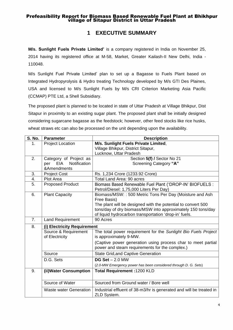
S. No. Parameter Description
1. Project Location M/s. Sunlight Fuels Private Limited, Village Bhikpur, District Sitapur, Lucknow, Uttar Pradesh
2. Category of Project as per EIA Notification &Amendments
Section 5(f) / Sector No 21 Screening Category “A”
3. Project Cost Rs. 1,234 Crore (1233.92 Crore)
4. Plot Area Total Land Area: 90 acres
5. Proposed Product Biomass Based Renewable Fuel Plant („DROP-IN‟ BIOFUELS : Petrol/Diesel: 1,75,000 Liters Per Day)
6. Plant Capacity Biomass/MSW: : 500 Metric Tons Per Day (Moisture and Ash Free Basis) The plant will be designed with the potential to convert 500 tons/day of dry biomass/MSW into approximately 150 tons/day of liquid hydrocarbon transportation „drop-in‟ fuels.
7. Land Requirement 90 Acres
8. (i) Electricity Requirement
Source & Requirement of Electricity
The total power requirement for the Sunlight Bio Fuels Project is approximately 9-MW.
(Captive power generation using process char to meet partial power and steam requirements for the complex.)
Source State Grid,and Captive Generation
D.G. Sets DG Set – 2.0 MW
(2.0-MW Emergency power has been considered through D. G. Sets)
9. (ii)Water Consumption Total Requirement :1200 KLD
Source of Water Sourced from Ground water / Bore well
Waste water Generation Industrial effluent of 38-m3/hr is generated and will be treated in ZLD System.

Prefeasibility Report for Biomass Based Renewable Fuel Plant at Bhikhpur
village of Sitapur District in Uttar Pradesh
5
Mode of Disposal Zero Liquid Discharge (ZLD)
10. (iii) Boiler Char based Steam Boiler (26.4 TPH) @ 79.4 kg/cm2a
11. (iv) Fuel (for H2 Plant) LPG to be sourced through tankers.
Seven (07) days storage facility (mounted bullets) is to be considered.
12. Employment Generation
Construction Period- 350 persons
Operation Period- 100 person
13. Nearest Highway State Highway No.21 (SH-21),2.0KM, West
Nearest Railway Station Hargaon Railway Station, 0.85 kms, SSW
Nearest Airport Nearest Airport is Lucknow, 106.0 kms , S
Prefeasibility Report for Biomass Based Renewable Fuel Plant at
Bhikhpur village of Sitapur District in Uttar Pradesh
6
2 INTRODUCTION
2.1 Brief Description of the Project
The proposed M/s Sunlight Fuels Pvt. Ltd., plant is planned to be located in state of Uttar
Pradesh at Village Bhikpur, Dist Sitapur in proximity to an existing sugar plant. The
proposed plant shall be initially designed considering sugarcane bagasse as the feedstock;
however, other feed stocks like rice husks, wheat straws,MSW, elephant grass etc can also
be processed on the unit depending upon the availability.
2.2 Project Proponent:
1. Mr. Sunil Singhal is the Director of the company. He has more than45years of
experience in sugar industry. He is a much respected individual in the Indian sugar
industry having helped establish many sugar refineries in India. Mr. Singhal holds
several patents on sugar & alcohol processing technology and has published and
delivered many papers at conferences worldwide. He is B. Tech. in Chemical
Engineering from Indian Institute of Technology, Kanpur. Mr Singhal is the promoter of
Chemical Systems Technologies Pvt. Ltd. (CSTPL) an ISO – 9001:2008 certified
Company.
2. Mr. Chand Bihari Patodia : Director
3. Mr. Ashish Patodia : Director
4. Mr. Nishant Singhal : Director
2.3 Need for the Project and its Importance to Region
Bio diesel and bio ethanol have a distinct chemical nature and so they can be accurately
defined by their chemical composition alone. For example, bio ethanol is ethanol and
biodiesel is a fatty acid methyl ester (FAME). In contrast bio-fuels generally consist of a
mixture of many different types of hydrocarbons, the properties of which, just like petroleum
fuels, is typically characterized by the mixtures „functional characteristics such as , specific
gravity, distillation profile, molecular weight, viscosity, acidity, etc. A true bio-fuel should be
able to be readily-dropped into the existing petroleum infrastructure and be handled in much
the same way as petroleum fuels without requiring any significant infrastructure
adjustments.

Prefeasibility Report for Biomass Based Renewable Fuel Plant at
Bhikhpur village of Sitapur District in Uttar Pradesh
7
Bio-fuels are currently attracting considerable attention. Some of the reasons are directly or
indirectly related to challenges to further increasing the markets for ethanol and biodiesel
bio-fuels such as their likely blend wall and supply constraints. Bio-fuels are better
positioned as they avoid blend wall concerns and also potentially make better use of
existing infrastructure (current inventory of petroleum refineries, supply channels and liquid
fuel powered combustion engines).
2.4 Demands-Supply Gap
GoI has set a goal of achieving 10% less import of crude and petroleum products by
2022.The bio-fuel projects will be able to fulfill this ambitious target by manufacturing in
India, using bio mass potentially available throughout the country. The current availability
of bio-diesel and bio ethanol is not sufficient to meet even 3.5% of the requirement for the
mandatory blending up to 10% which is proposed to be further increased to 20%. Only
such bio fuels as are proposed to be manufactured by this project can meet this vast gap.
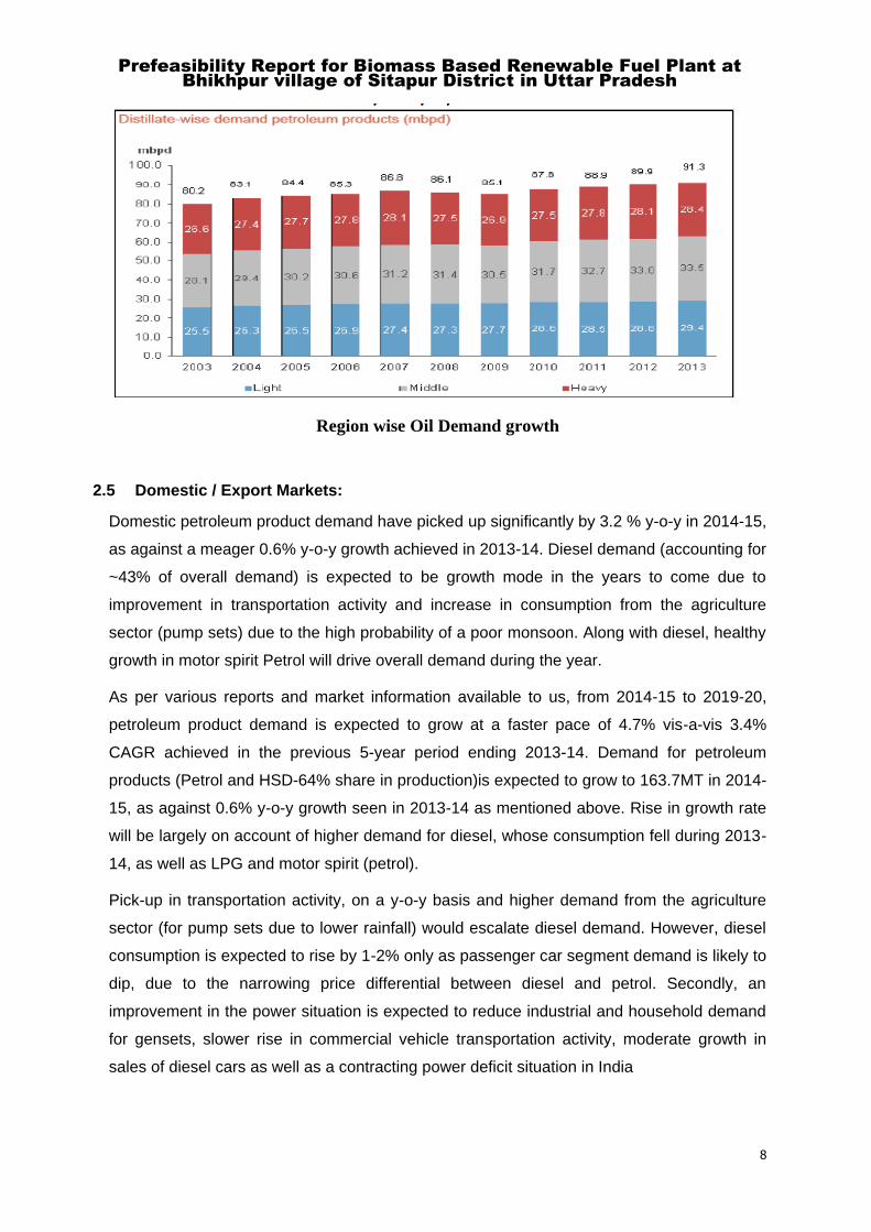
During 2008-2013, global consumption of petroleum products (PETROL and HSD-64%
share in production) grew at 1.2% CAGR to 91.3 MBPD. Of these, light and middle
distillates grew at a CAGR of 1.5 and 1.3 %, respectively, while the consumption of heavy
distillates grew at a slower pace of 0.7%. Majority of the incremental demand in the past 5
years came from developing regions like Asia Pacific (4.5 MBPD), and Middle East (1.3
MBPD). Demand declined in most developed regions like the North America (-0.6 MBPD),
Europe and Eurasia region (-1.4 MBPD) due to a shift towards cleaner fuels and slower
GDP growth rates. While demand growth of non OECD countries slowed down to 3.1% y-
o-y, a 2% increase in demand from US (accounting for 21% of global petroleum product
demand in 2013) resulted in consumption remaining flat in OECD countries. Demand from
OECD countries declined by 1.1% y-o-y in 2012.
The crude oil demand shall record a CAGR of 1% during the next 5 years (as compared to
1.2%CAGR in previous 5 years) and reach 95.8 Million Barrel per day by 2018.
Prefeasibility Report for Biomass Based Renewable Fuel Plant at
Bhikhpur village of Sitapur District in Uttar Pradesh
8
Region wise Oil Demand growth
2.5 Domestic / Export Markets:
Domestic petroleum product demand have picked up significantly by 3.2 % y-o-y in 2014-15,
as against a meager 0.6% y-o-y growth achieved in 2013-14. Diesel demand (accounting for
~43% of overall demand) is expected to be growth mode in the years to come due to
improvement in transportation activity and increase in consumption from the agriculture
sector (pump sets) due to the high probability of a poor monsoon. Along with diesel, healthy
growth in motor spirit Petrol will drive overall demand during the year.
As per various reports and market information available to us, from 2014-15 to 2019-20,
petroleum product demand is expected to grow at a faster pace of 4.7% vis-a-vis 3.4%
CAGR achieved in the previous 5-year period ending 2013-14. Demand for petroleum
products (Petrol and HSD-64% share in production)is expected to grow to 163.7MT in 2014-
15, as against 0.6% y-o-y growth seen in 2013-14 as mentioned above. Rise in growth rate
will be largely on account of higher demand for diesel, whose consumption fell during 2013-
14, as well as LPG and motor spirit (petrol).
Pick-up in transportation activity, on a y-o-y basis and higher demand from the agriculture
sector (for pump sets due to lower rainfall) would escalate diesel demand. However, diesel
consumption is expected to rise by 1-2% only as passenger car segment demand is likely to
dip, due to the narrowing price differential between diesel and petrol. Secondly, an
improvement in the power situation is expected to reduce industrial and household demand
for gensets, slower rise in commercial vehicle transportation activity, moderate growth in
sales of diesel cars as well as a contracting power deficit situation in India
Prefeasibility Report for Biomass Based Renewable Fuel Plant at
Bhikhpur village of Sitapur District in Uttar Pradesh
9
In case of petrol, decline in petrol prices, reduction in gap between petrol and diesel prices
and healthy demand from the two wheeler segment (accounting for 2/3 of the total domestic
petrol demand) are some of the factors driving consumption. On a flip side slower rise in the
number of vehicles plying on petrol as well as improvement in fuel efficiencies will restrict
PETROL demand growth As per various report, in the long term, demand for petroleum
products (PETROL and HSD-64% share in production)is expected to rise at 4.7% CAGR to
~206-MTPA by 2019-20 vis-a-vis 3.4% CAGR recorded during 2008-09 to 2013-14.
2.6 Employment Generation (Direct and Indirect) due to the Project
The National Policy on Bio-fuels „released in 2009, foresees bio-fuels as a potential means
to stimulate rural development and generate employment opportunities, as well as aspires
to reap environmental and economic benefits arising out of their large scale use. The project
shall provide employment for 100 persons during operation phase and about 350 persons
shall be required during construction period of the project. Further Transport business,
vehicle drivers and attendants, repairing workshops, grocery and retail stores, school,
coaching centers, restaurants, self- employed persons like tailors, carpenters, plumbers,
electricians, etc will also get indirect employment / livelihood opportunity from this project.
2.7 Type of Project including interlinked and interdependent Projects, if any
The proposed project falls under „Section 5(f)’ / Sector-21 (Industries based on processing
of petroleum fractions & natural gas and/or reforming to aromatics) Production of Diesel
&„Category “A”. Proposed project is interlinked project.
Plant Capacity: The plant will be designed with the potential to convert 500 tons/day of dry
bio-mass into approximately 150 tons/day of liquid hydrocarbon „drop-in‟transportation fuel.
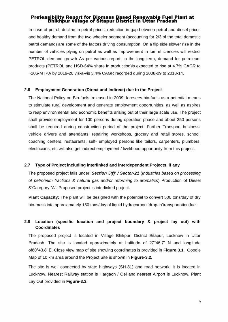
2.8 Location (specific location and project boundary & project lay out) with
Coordinates
The proposed project is located in Village Bhikpur, District Sitapur, Lucknow in Uttar
Pradesh. The site is located approximately at Latitude of 27°46.7‟ N and longitude
of80°43.8‟ E. Close view map of site showing coordinates is provided in Figure 3.1. Google
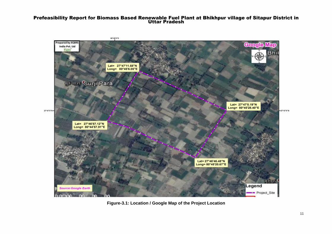
Map of 10 km area around the Project Site is shown in Figure-3.2.
The site is well connected by state highways (SH-81) and road network. It is located in
Lucknow. Nearest Railway station is Hargaon / Oel and nearest Airport is Lucknow. Plant
Lay Out provided in Figure-3.3.

Prefeasibility Report for Biomass Based Renewable Fuel Plant at
Bhikhpur village of Sitapur District in Uttar Pradesh
10
2.9 Details of alternate sites considered and the basis of selecting the proposed site,
particularly the environmental considerations gone into should be highlighted
No alternate site considered due to availability of the raw material in proposed project
location. The proposed project is located in Village Bhikhpur, Tehsil / District Sitapur, in
Uttar Pradesh. The site is located approximately at Latitude of 27°46.7‟ N and longitude of
80°43.8‟ E.
The site is well connected by State Highways (SH-21)/SH-81 and road network. Nearest
Railway station is Hargaon / Oel and nearest Airport is Lucknow, hence no alternate site
considered.
2.10 Technology and Process Description
The process technology for the proposed plant is licensed to Sunlight Fuels Pvt. Ltd by
CCMAP, a Singapore-based affiliate of CRI Catalyst Company LP (CRI), a global catalyst
technology company of the Shell Group. This proprietary technology is licensed with name
„IH2 technology‟ which is based on continuous catalytic thermo-chemical process. This
technology converts agricultural, forest and sorted municipal residues into fungible
hydrocarbon transportation fuels.
“DROP IN” BIOFUELS: “DROP IN” bio-fuels are substitute for conventional fossil fuels(
Petrol/ Diesel/ ATF) that are completely interchangeable and compatible with conventional
fuels. A “Drop-in” bio-fuel doesn‟t require alteration or modification of the engine, fuel
system, or the fuel distribution network and can be used “ as is” in existing engines in pure
form and/or blended in any ratio with other fuels.
DESCRIPTION: Renewable hydrocarbon “ drop-in” bio-fuels are fuels produced from
Biomass/ MSW sources through hydro-catalytic pyrolysis route and are identical to the
Petrol/ Diesel /ATFin current use.“ Drop-In” refers to those renewable fuels that can be
readily put into an existing car/truck/ bus/ railway etc. engine, and used exactly as the
conventional fossil fuels without any further modification, and by using the existing
distribution infrastructure of the fuel outlets such as petrol pumps.
The “drop-in” bio-fuels shall conform at all times to the prevalent Indian BS standards ( IV.
VI) fixed by the Government of India for Petrol/Diesel/ATF.
Prefeasibility Report for Biomass Based Renewable Fuel Plant at Bhikhpur village of Sitapur District in
Uttar Pradesh
11
Figure-3.1: Location / Google Map of the Project Location
Prefeasibility Report for Biomass Based Renewable Fuel Plant at Bhikhpur village of Sitapur District in
Uttar Pradesh
12
Figure-3.3: Plant Location (Google) Map
Prefeasibility Report for Biomass Based Renewable Fuel Plant at Bhikhpur village of Sitapur District in
Uttar Pradesh
13
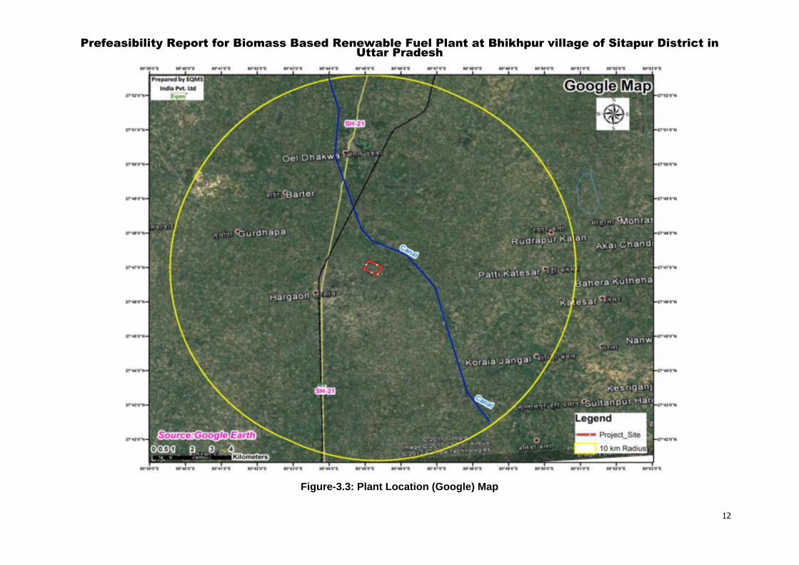
Figure-3.2: Plant Layout for the Proposed Project
Prefeasibility Report for Biomass Based Renewable Fuel Plant at
Bhikhpur village of Sitapur District in Uttar Pradesh
14
2.11 Manufacturing Process:
The process technology for the proposed plant is licensed to Sunlight Fuels Pvt. Ltd by
CCMAP, a Singapore-based affiliate of CRI Catalyst Company LP (CRI), a global catalyst
technology company of the Shell Group. This proprietary technology is licensed with name
„IH2 technology‟ which is based on continuous catalytic thermo-chemical process. This
technology converts agricultural, forest and sorted municipal residues into fungible
hydrocarbon transportation fuels.
IH2 Technology
The IH2 technology is an efficient conversion route for agricultural and other residues
which allows for production of clean transportation fuels from renewable resources. The
process was developed by Gas Technology Institute (GTI) of Des Plaines, IL in 2009.
GTI and CRI have jointly continued development of the technology since 2010. CRI has
been granted exclusive worldwide licensing rights.
The IH2 process has four primary elements. The first is biomass conditioning i.e. sizing
and drying to 10 – 30wt% moisture. The second element involves hydro de-oxygenation of
the volatilized biomass to produce a raw hydrocarbon product over proprietary CRI
catalysts in the presence of low–pressure hydrogen. This serves both to remove oxygen
and cap reactive free radicals to provide a stable hydrocarbon product. The third element
is a fixed–bed hydro treater, which uses other proprietary CRI catalysts to polish the first–
stage product and transform it into a finished hydrocarbon fuel or blend stock.
The fourth element is a Hydrogen Manufacturing Unit (HMU), which converts light gases
generated in the first–stage to renewable hydrogen, in sufficient quantity to supply all
process needs.
Further details of the process are presented in the subsequent chapters.
Flow chart for liquid hydrocarbon transportation fuel manufacturing is shown in Figure-3.4
Process Description: Detailed process description is provided in Annexure-I

Prefeasibility Report for Biomass Based Renewable Fuel Plant at Bhikhpur village of Sitapur
District in Uttar Pradesh
15
Figure-3.4: Generalized Flow Chart for Liquid Hydrocarbon Transportation Fuel Manufacturing
Prefeasibility Report for Biomass Based Renewable Fuel Plant at
Bhikhpur village of Sitapur District in Uttar Pradesh
16
2.12 Raw Materials
RAW MATERIAL – BIOMASS
The IH2 Process is very versatile; it can process almost any Biomass, including MSW
(Municipal Solid Waste). Thus, some of the possible feedstock biomass possible is;
List of Raw Material
Wheat Straw
Paddy Straw
Millet
Bagasse (from Sugarcane)
Wood Waste
Saw Dust
MSW
Elephant Grass
The key issue with any Biomass based project is the aggregation and the transport cost of
biomass because of its low bulk density. This cost can exceed the cost of the biomass itself if
the distances from the farm to the production facility are more than 50 km.
Keeping this in view the project is being almost co-located adjacent to an operating sugar mill of
12,000TPD sugarcane crushing capacity. The bagasse produced at this factory is 4,100
tons/day out of which 3000TPD is used in their boilers for their power and steam requirements.
Thus, it has been ensured that 1000TPD of bagasse will be readily available for the proposed
project. The bagasse coming from the sugar mill normally contains around 47-48% moisture
and 2-3% ash. Therefore, we have ensured that 500 TPD of bagasse MAF (Moisture & Ash
Free) will be supplied to the project.
Attached is the letter from Birla Sugar Mills, Hargaon committing the supply of bagasse.
Sugarcane is a seasonal crop, with the season running 150 – 180 days between late October
&April. Therefore, if the project were to be based on only bagasse as the feed input, then the
question arises for the feedstock supply for the balance 180 – 150 days for the 330 days/year
manufacturing schedule of the project.
There are two ways that this has been approached.
1. A 20 acre area is planned to store the bagasse for the sugarcane off-season period
where bagasse will be stored after buying from the other sugar mills in the area. This
has been mapped-out, please see the attached map that shows each and every village
in a 50 km radius and also shows the several sugar mills in this area. We have data of

Prefeasibility Report for Biomass Based Renewable Fuel Plant at
Bhikhpur village of Sitapur District in Uttar Pradesh
17
all the cane farmers in this area, their land holding size, and quantity of cane cultivated
per season.
2. The other initiative is to grow Elephant Grass on marginal land by introducing an elaborate
programme of buying back from over 3000 farmers their output of Elephant Grass that will be
scientifically cultivated.
Elephant Grass can give 3-4 crops per year and requires very little amounts of water and
fertilizer.
The farmers will get a better income from Elephant Grass compared to their growing sugarcane
on that land. Plus, they will have an assured sale of their crop.
Two neighboring districts have been surveyed in detail and the whole programme drawn-up for
this initiative.
This alternate biomass will also hugely DE-RISK the project by not making it dependent on a
single source of raw material.
2.13 Additives and Chemicals
Ethanol
LPG
Nitrogen
Amine
Water Treatment chemicals
Tankage: Total -12 No's
Petrol/Gasoline – 3 No's
Diesel – 3 No‟s
Intermediate – 2 No‟s
Off Spec- 1 No‟s
LPG – 2 No‟s Mounded Bullets
Ethanol – 1 No‟s
2.14 Raw material required along with estimated quantity, likely source, marketing area
of final products, mode of transport of raw material and finished product.
2.14.1 Transportation details of Raw Materials
The transportation of raw materials will be done by trucks and trolley using local existing road
network.
Prefeasibility Report for Biomass Based Renewable Fuel Plant at
Bhikhpur village of Sitapur District in Uttar Pradesh
18
2.15 Availability of water its source, energy/power requirement and source should be
given
Water Requirement & Source
The proposed project is located in Village Bhikhpur, District Sitapur in Uttar Pradesh. The site
is located approximately at Latitude of 27°46.7‟ N and longitude of 80°43.8‟ E.
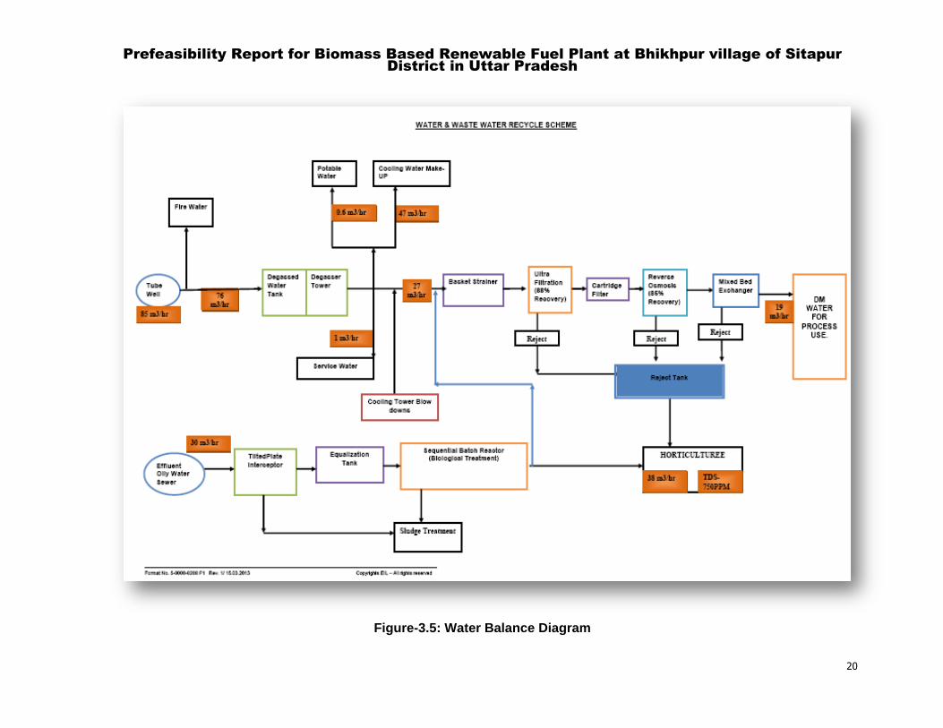
Total water requirement will be 1200 KLD, which is sourced from bore well. Permission for
drawing ground water shall be obtained from concerned authority. Recycled treated water
shall be used in fire fighting and greenbelt development. Water Balance diagram is provided
in Figure 3.5.
Energy/Power Requirement
The total power requirement for the Sunlight Bio Fuels project is approximately 9-MW.
Captive power generation using process char to be considered for power and steam
generation for the entire complex.
2.0-MW Emergency power has been considered through Diesel Gen sets.
2.15.1 Fuel
LPG is considered to be available for H2 generation plant.
LPG is to be sourced through road tankers.
Seven (07) days storage facility (mounted bullets) is to be considered.
2.15.2 Quantity of waste to be generated (liquid and solid) and scheme for their
management /disposal
2.15.3 Waste Water Generation and Utilization:
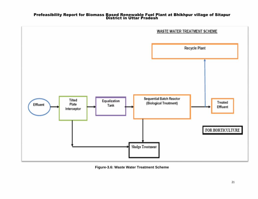
Industrial effluent of 38-m3/hr is generated and will be treated in ZLD System. Part of the
treated effluent will be used for firefighting and horticulture purposes and rest of the treated
water shall be reused in process
Introduction
Several measures are proposed to be incorporated at the designs stage towards minimizing
the generation of wastewater and treatment of the generated effluent.
Some of these measures are described below:
Prefeasibility Report for Biomass Based Renewable Fuel Plant at
Bhikhpur village of Sitapur District in Uttar Pradesh
19
Appropriate segregation and collection philosophy (separate sewers for process waste,
contaminated rainwater, cooling tower blow down, boiler blow down, catalyst
regeneration waste, etc.) will be incorporated for various effluents depending on
individual stream characteristics.
A comprehensive wastewater management system consisting of state of art sequencing
batch reactor and tertiary treatment consisting of Reverse Osmosis membrane will be
adopted for maximizing reuse and recycle of treated effluent.
Closed blow down system will be incorporated for hydrocarbon liquid discharges in all
the process units, which will reduce the wastewater load to ETP both in terms of
quantum load and quality. This is another of the in-plant control measures.
Most of the stripped water from non-hydro processed Sour Water Stripper will be reused
as make-up water and the stripped water from hydro processed Sour Water Stripper will
be reused in hydro processing units. This in-plant control measure will reduce the net
wastewater load to the ETP considerably.
Process area will be paved to avoid contamination of soil/sub-soil/ground water in case
of accidental spill/leakage of hydrocarbon liquids.
Prefeasibility Report for Biomass Based Renewable Fuel Plant at Bhikhpur village of Sitapur
District in Uttar Pradesh
20
Figure-3.5: Water Balance Diagram
Prefeasibility Report for Biomass Based Renewable Fuel Plant at Bhikhpur village of Sitapur
District in Uttar Pradesh
21
Figure-3.6: Waste Water Treatment Scheme
Prefeasibility Report for Biomass Based Renewable Fuel Plant at
Bhikhpur village of Sitapur District in Uttar Pradesh
22
3 SITE ANALYSIS
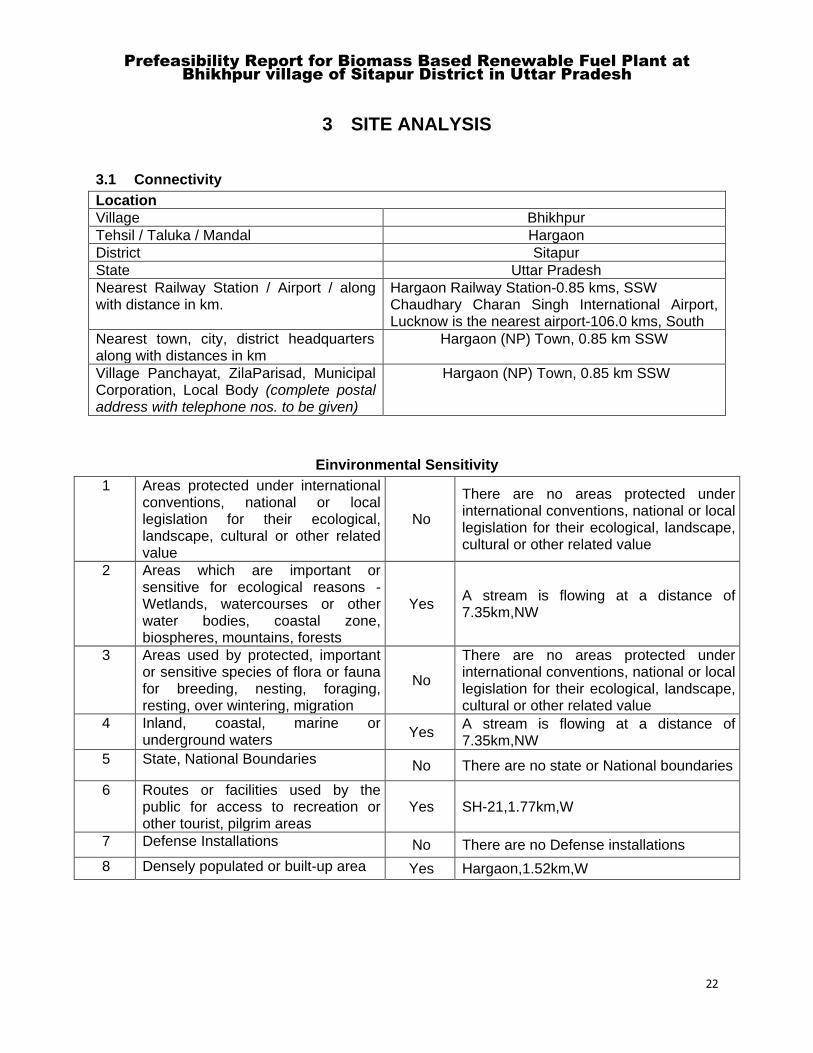
3.1 Connectivity
Location
Village Bhikhpur
Tehsil / Taluka / Mandal Hargaon
District Sitapur
State Uttar Pradesh
Nearest Railway Station / Airport / along with distance in km.
Hargaon Railway Station-0.85 kms, SSW Chaudhary Charan Singh International Airport, Lucknow is the nearest airport-106.0 kms, South
Nearest town, city, district headquarters along with distances in km
Hargaon (NP) Town, 0.85 km SSW
Village Panchayat, ZilaParisad, Municipal Corporation, Local Body (complete postal address with telephone nos. to be given)
Hargaon (NP) Town, 0.85 km SSW
Einvironmental Sensitivity
1 Areas protected under international conventions, national or local legislation for their ecological, landscape, cultural or other related value
No
There are no areas protected under international conventions, national or local legislation for their ecological, landscape, cultural or other related value
2 Areas which are important or sensitive for ecological reasons -Wetlands, watercourses or other water bodies, coastal zone, biospheres, mountains, forests
Yes A stream is flowing at a distance of 7.35km,NW
3 Areas used by protected, important or sensitive species of flora or fauna for breeding, nesting, foraging, resting, over wintering, migration
No
There are no areas protected under international conventions, national or local legislation for their ecological, landscape, cultural or other related value
4 Inland, coastal, marine or underground waters
Yes A stream is flowing at a distance of 7.35km,NW
5 State, National Boundaries No There are no state or National boundaries
6 Routes or facilities used by the public for access to recreation or other tourist, pilgrim areas
Yes SH-21,1.77km,W
7 Defense Installations No There are no Defense installations
8 Densely populated or built-up area Yes Hargaon,1.52km,W
Prefeasibility Report for Biomass Based Renewable Fuel Plant at
Bhikhpur village of Sitapur District in Uttar Pradesh
23
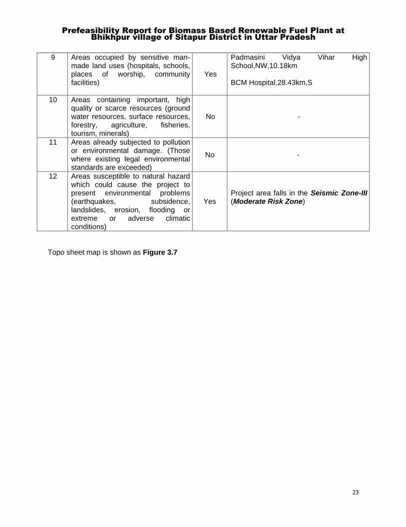
9 Areas occupied by sensitive man-made land uses (hospitals, schools, places of worship, community facilities)
Yes
Padmasini Vidya Vihar High School,NW,10.18km BCM Hospital,28.43km,S
10 Areas containing important, high quality or scarce resources (ground water resources, surface resources, forestry, agriculture, fisheries, tourism, minerals)
No -
11 Areas already subjected to pollution or environmental damage. (Those where existing legal environmental standards are exceeded)
No -
12 Areas susceptible to natural hazard which could cause the project to present environmental problems (earthquakes, subsidence, landslides, erosion, flooding or extreme or adverse climatic conditions)
Yes Project area falls in the Seismic Zone-III (Moderate Risk Zone)
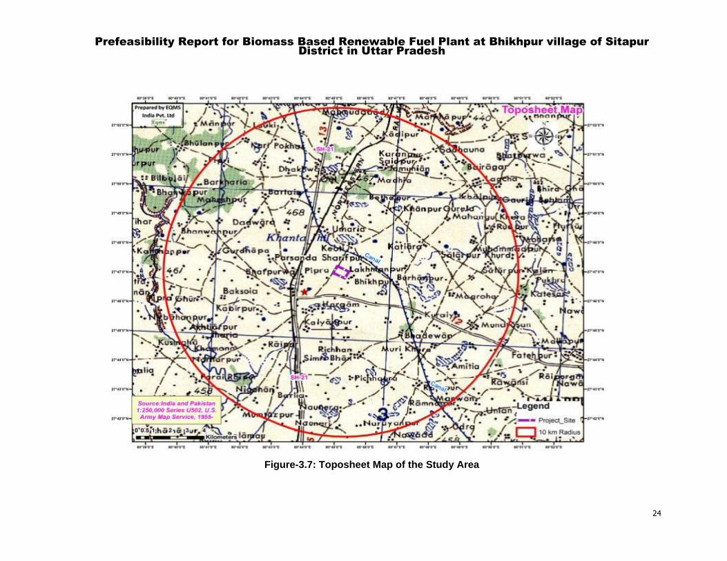
Topo sheet map is shown as Figure 3.7
Prefeasibility Report for Biomass Based Renewable Fuel Plant at Bhikhpur village of Sitapur
District in Uttar Pradesh
24
Figure-3.7: Toposheet Map of the Study Area
Prefeasibility Report for Biomass Based Renewable Fuel Plant at
Bhikhpur village of Sitapur District in Uttar Pradesh
25
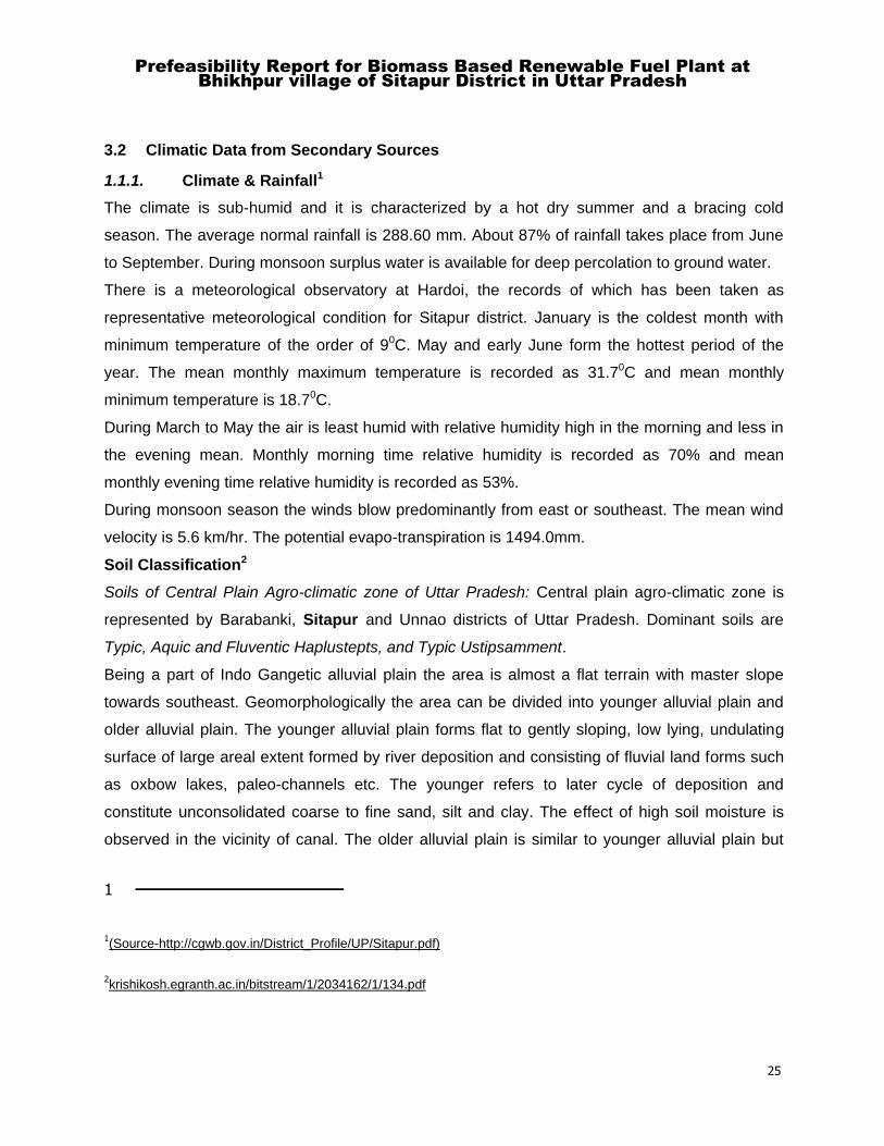
3.2 Climatic Data from Secondary Sources
1.1.1. Climate & Rainfall1
The climate is sub-humid and it is characterized by a hot dry summer and a bracing cold
season. The average normal rainfall is 288.60 mm. About 87% of rainfall takes place from June
to September. During monsoon surplus water is available for deep percolation to ground water.
There is a meteorological observatory at Hardoi, the records of which has been taken as
representative meteorological condition for Sitapur district. January is the coldest month with
minimum temperature of the order of 90C. May and early June form the hottest period of the
year. The mean monthly maximum temperature is recorded as 31.70C and mean monthly
minimum temperature is 18.70C.
During March to May the air is least humid with relative humidity high in the morning and less in
the evening mean. Monthly morning time relative humidity is recorded as 70% and mean
monthly evening time relative humidity is recorded as 53%.
During monsoon season the winds blow predominantly from east or southeast. The mean wind
velocity is 5.6 km/hr. The potential evapo-transpiration is 1494.0mm.
Soil Classification2
Soils of Central Plain Agro-climatic zone of Uttar Pradesh: Central plain agro-climatic zone is
represented by Barabanki, Sitapur and Unnao districts of Uttar Pradesh. Dominant soils are
Typic, Aquic and Fluventic Haplustepts, and Typic Ustipsamment.
Being a part of Indo Gangetic alluvial plain the area is almost a flat terrain with master slope
towards southeast. Geomorphologically the area can be divided into younger alluvial plain and
older alluvial plain. The younger alluvial plain forms flat to gently sloping, low lying, undulating
surface of large areal extent formed by river deposition and consisting of fluvial land forms such
as oxbow lakes, paleo-channels etc. The younger refers to later cycle of deposition and
constitute unconsolidated coarse to fine sand, silt and clay. The effect of high soil moisture is
observed in the vicinity of canal. The older alluvial plain is similar to younger alluvial plain but
1
1(Source-http://cgwb.gov.in/District_Profile/UP/Sitapur.pdf)
2krishikosh.egranth.ac.in/bitstream/1/2034162/1/134.pdf

Prefeasibility Report for Biomass Based Renewable Fuel Plant at
Bhikhpur village of Sitapur District in Uttar Pradesh
26
formed at earlier stage of depositional regimes, comprising older unconsolidated alluvium. The
paleo-channels are buried channels filled in with sand silt and clay of varying lithology, where as
oxbow lakes are crescent shaped cut off meander with water and composed of unconsolidated
alluvial materials. The area is characterized by ravines. These are small, narrow, deep
depressions dissected and irregular surface usually produced by surface run off. These occur
along Gomti River& its tributaries. The ravines comprise unconsolidated alluvial material of
varying lithology mainly with fine sediments and developed in older alluvium. The chief verities of
soil are bhur or sand, dumat or loam and matiyar or clay. Bhur is formed along the high banks of
rivers and streams, matiyar is found in depressions in the upland while dumat occurs in rest of
the district.
1.1.2. Seismic Considerations
According to the Seismic Zonation and Intensity Map of India, the state of Uttar Pradesh falls
under Moderate Risk Zone-III.As per the 2002 Bureau of Indian Standards (BIS) map, study
area falls in Moderate Risk Zone-III.
Zone-III
The Andaman and Nicobar Islands, parts of Kashmir, Western Himalayas fall under this zone.
This zone is classified as Moderate Damage Risk Zone which is liable to MSK VII and also 7.8
The IS code assigns zone factor of 0.16 for Zone 3.
Source-https://www.mapsofindia.com/maps/india/seismiczone.htm
Figure-3.8: Seismic Zone Map of India
Prefeasibility Report for Biomass Based Renewable Fuel Plant at
Bhikhpur village of Sitapur District in Uttar Pradesh
27
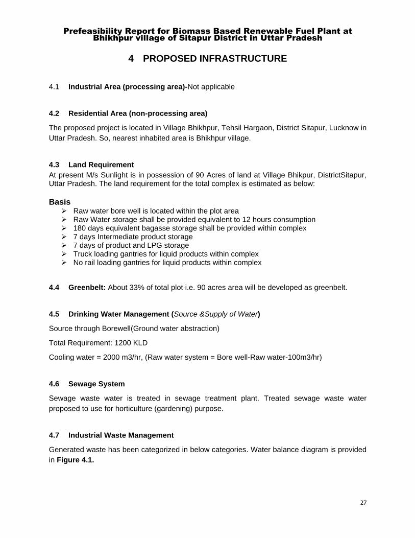
4 PROPOSED INFRASTRUCTURE
4.1 Industrial Area (processing area)-Not applicable
4.2 Residential Area (non-processing area)
The proposed project is located in Village Bhikhpur, Tehsil Hargaon, District Sitapur, Lucknow in
Uttar Pradesh. So, nearest inhabited area is Bhikhpur village.
4.3 Land Requirement
At present M/s Sunlight is in possession of 90 Acres of land at Village Bhikpur, DistrictSitapur, Uttar Pradesh. The land requirement for the total complex is estimated as below:
Basis Raw water bore well is located within the plot area Raw Water storage shall be provided equivalent to 12 hours consumption 180 days equivalent bagasse storage shall be provided within complex 7 days Intermediate product storage 7 days of product and LPG storage Truck loading gantries for liquid products within complex No rail loading gantries for liquid products within complex
4.4 Greenbelt: About 33% of total plot i.e. 90 acres area will be developed as greenbelt.
4.5 Drinking Water Management (Source &Supply of Water)
Source through Borewell(Ground water abstraction)
Total Requirement: 1200 KLD
Cooling water = 2000 m3/hr, (Raw water system = Bore well-Raw water-100m3/hr)
4.6 Sewage System
Sewage waste water is treated in sewage treatment plant. Treated sewage waste water
proposed to use for horticulture (gardening) purpose.
4.7 Industrial Waste Management
Generated waste has been categorized in below categories. Water balance diagram is provided
in Figure 4.1.
Prefeasibility Report for Biomass Based Renewable Fuel Plant at
Bhikhpur village of Sitapur District in Uttar Pradesh
28
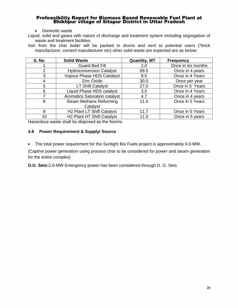
Domestic waste Liquid, solid and gases with nature of discharge and treatment system including segregation of
waste and treatment facilities. Ash from the char boiler will be packed in drums and sent to potential users (*brick
manufacturer, cement manufacturer etc) other solid waste are expected are as below:
S. No Solid Waste Quantity, MT Frequency
1 Guard Bed Fill 2.0 Once in six months
2 Hydroconversion Catalyst 69.5 Once in 4 years
3 Vapour Phase HDS Cattalyst 8.5 Once in 4 Years
4 Zinc Oxide 30.0 Once per year
5 LT Shift Catalyst 27.0 Once in 5 Years
6 Liquid Phase HDS catalyst 3.0 Once in 4 Years
7 Aromatics Saturation catalyst 4.7 Once in 4 years
8 Steam Methane Reforming Catalyst
11.5 Once in 5 Years
9 H2 Plant LT Shift Catalyst 11.7 Once in 5 Years
10 H2 Plant HT Shift Catalyst 11.0 Once in 5 years
Hazardous waste shall be disposed as the Norms. 4.8 Power Requirement & Supply/ Source
The total power requirement for the Sunlight Bio Fuels project is approximately 9.0-MW.
(Captive power generation using process char to be considered for power and steam generation
for the entire complex)
D.G. Sets:2.0-MW Emergency power has been considered through D. G. Sets
Prefeasibility Report for Biomass Based Renewable Fuel Plant at
Bhikhpur village of Sitapur District in Uttar Pradesh
29
5 REHABILITATION AND RESETTLEMENTS (R& R) PLAN
5.1 Policy to be adopted (central/state) in respect of the project affected persons
including home oustees, land oustees and landless laborers (a brief outline to be
given)
No settlement or any man made structure is present on the identified land proposed for the
project. No displacement shall be done within the land identified for the project. Hence no
R&R issues related to project. However the land shall be purchased through mutual
agreement with the land owner. Compensation shall be made as per the state R&R policy.
Prefeasibility Report for Biomass Based Renewable Fuel Plant at
Bhikhpur village of Sitapur District in Uttar Pradesh
30
6 PROJECT SCHEDULE AND COST ESTIMATE
6.1 Likely date of start of construction and likely data of completion (time schedule for
the project to be given)
Project work will be started after getting the environmental clearance.
(It is necessary to make a detailed schedule of things to do for each activity and a time frame for
each activity. Proper project management and regular follow up of these activities are necessary
for overall achievement of the deadline as per the implementation schedule and to avoid any
time and cost overrun. The company proposes to avail the services of EIL for EPC/EPMC to
ensure that the implementation schedule is met.)
6.2 Estimated Project Cost along with Analysis in terms of Economic viability of the
Project.
Cost of Estimates of the Greenfield ProjectRs. 1,234 Crore (1233.92 Crore)(INR).
The financial projections for the project have been prepared based on the initial information
given by EIL Ltd. with respect to sale price, operating expenses, capital expenditure phasing,
product yield etc., with other information. These financial projections with present assumptions
are subject to change once the documents such as technical project report, detailed feasibility
report, various quotations, certified material balancing chart, quotations for selling prices of
output and operating expenses etc. are finalised. With the above assumptions, the average debt
service coverage ratio (DSCR) of the project works out to be 1.90 times with minimum DSCR of
1.62 times for base case and project internal rate of return (IRR) is 18.01%(against a weighted
average cost of capital of 8.52%).
Project Cost and Means of Finance
Project Cost
Sr. No Particulars Cost (Rs. Crore)
1 Land & Site Development 36.42
2 Building Works 50.09
3 License Fees 19.73
Prefeasibility Report for Biomass Based Renewable Fuel Plant at
Bhikhpur village of Sitapur District in Uttar Pradesh
31
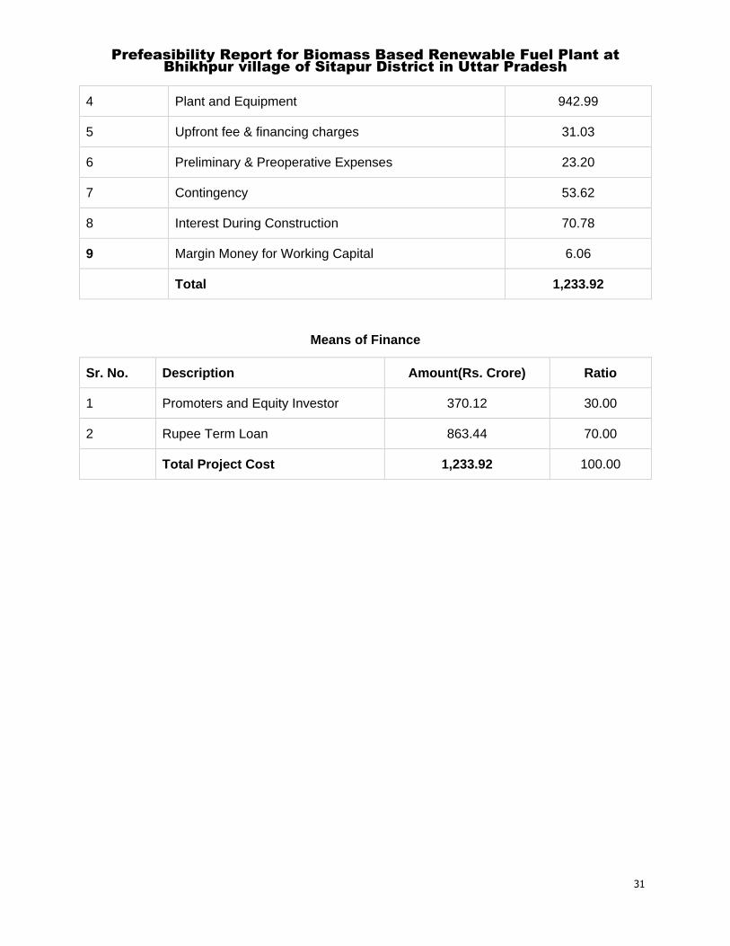
4 Plant and Equipment 942.99
5 Upfront fee & financing charges 31.03
6 Preliminary & Preoperative Expenses 23.20
7 Contingency 53.62
8 Interest During Construction 70.78
9 Margin Money for Working Capital 6.06
Total 1,233.92
Means of Finance
Sr. No. Description Amount(Rs. Crore) Ratio
1 Promoters and Equity Investor 370.12 30.00
2 Rupee Term Loan 863.44 70.00
Total Project Cost 1,233.92 100.00
ANNEXURE-I PROCESS DESCRIPTION
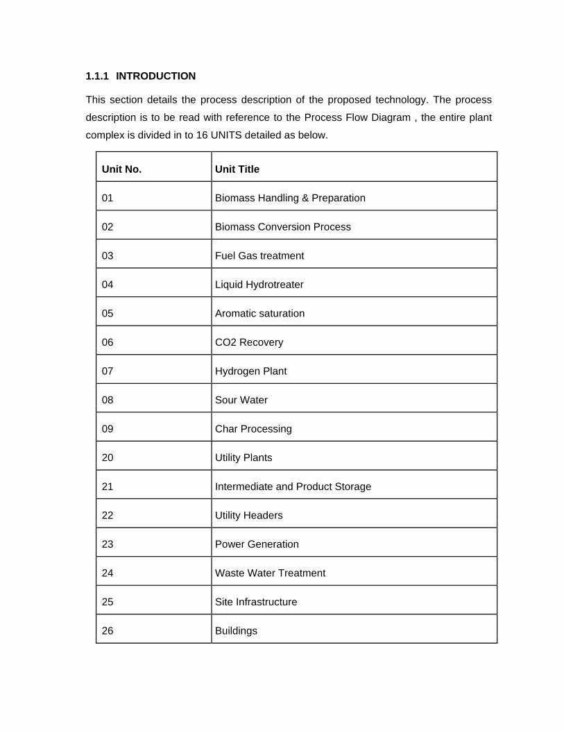
1.1.1 INTRODUCTION
This section details the process description of the proposed technology. The process
description is to be read with reference to the Process Flow Diagram , the entire plant
complex is divided in to 16 UNITS detailed as below.
Unit No. Unit Title
01 Biomass Handling & Preparation
02 Biomass Conversion Process
03 Fuel Gas treatment
04 Liquid Hydrotreater
05 Aromatic saturation
06 CO2 Recovery
07 Hydrogen Plant
08 Sour Water
09 Char Processing
20 Utility Plants
21 Intermediate and Product Storage
22 Utility Headers
23 Power Generation
24 Waste Water Treatment
25 Site Infrastructure
26 Buildings
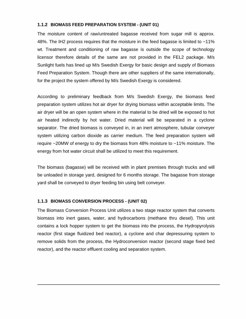
1.1.2 BIOMASS FEED PREPARATION SYSTEM - (UNIT 01) The moisture content of raw/untreated bagasse received from sugar mill is approx.
48%. The IH2 process requires that the moisture in the feed bagasse is limited to ~11%
wt. Treatment and conditioning of raw bagasse is outside the scope of technology
licensor therefore details of the same are not provided in the FEL2 package. M/s
Sunlight fuels has lined up M/s Swedish Exergy for basic design and supply of Biomass
Feed Preparation System. Though there are other suppliers of the same internationally,
for the project the system offered by M/s Swedish Exergy is considered.
According to preliminary feedback from M/s Swedish Exergy, the biomass feed
preparation system utilizes hot air dryer for drying biomass within acceptable limits. The
air dryer will be an open system where in the material to be dried will be exposed to hot
air heated indirectly by hot water. Dried material will be separated in a cyclone
separator. The dried biomass is conveyed in, in an inert atmosphere, tubular conveyer
system utilizing carbon dioxide as carrier medium. The feed preparation system will
require ~20MW of energy to dry the biomass from 48% moisture to ~11% moisture. The
energy from hot water circuit shall be utilized to meet this requirement.
The biomass (bagasse) will be received with in plant premises through trucks and will
be unloaded in storage yard, designed for 6 months storage. The bagasse from storage
yard shall be conveyed to dryer feeding bin using belt conveyer.
1.1.3 BIOMASS CONVERSION PROCESS - (UNIT 02) The Biomass Conversion Process Unit utilizes a two stage reactor system that converts
biomass into inert gases, water, and hydrocarbons (methane thru diesel). This unit
contains a lock hopper system to get the biomass into the process, the Hydropyrolysis
reactor (first stage fluidized bed reactor), a cyclone and char depressuring system to
remove solids from the process, the Hydroconversion reactor (second stage fixed bed
reactor), and the reactor effluent cooling and separation system.
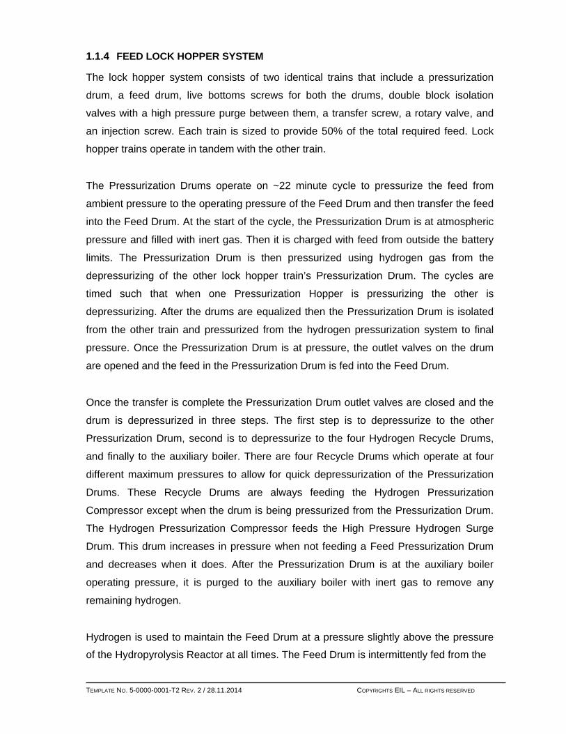
1.1.4 FEED LOCK HOPPER SYSTEM The lock hopper system consists of two identical trains that include a pressurization
drum, a feed drum, live bottoms screws for both the drums, double block isolation
valves with a high pressure purge between them, a transfer screw, a rotary valve, and
an injection screw. Each train is sized to provide 50% of the total required feed. Lock
hopper trains operate in tandem with the other train.
The Pressurization Drums operate on ~22 minute cycle to pressurize the feed from
ambient pressure to the operating pressure of the Feed Drum and then transfer the feed
into the Feed Drum. At the start of the cycle, the Pressurization Drum is at atmospheric
pressure and filled with inert gas. Then it is charged with feed from outside the battery
limits. The Pressurization Drum is then pressurized using hydrogen gas from the
depressurizing of the other lock hopper train’s Pressurization Drum. The cycles are
timed such that when one Pressurization Hopper is pressurizing the other is
depressurizing. After the drums are equalized then the Pressurization Drum is isolated
from the other train and pressurized from the hydrogen pressurization system to final
pressure. Once the Pressurization Drum is at pressure, the outlet valves on the drum
are opened and the feed in the Pressurization Drum is fed into the Feed Drum.
Once the transfer is complete the Pressurization Drum outlet valves are closed and the
drum is depressurized in three steps. The first step is to depressurize to the other
Pressurization Drum, second is to depressurize to the four Hydrogen Recycle Drums,
and finally to the auxiliary boiler. There are four Recycle Drums which operate at four
different maximum pressures to allow for quick depressurization of the Pressurization
Drums. These Recycle Drums are always feeding the Hydrogen Pressurization
Compressor except when the drum is being pressurized from the Pressurization Drum.
The Hydrogen Pressurization Compressor feeds the High Pressure Hydrogen Surge
Drum. This drum increases in pressure when not feeding a Feed Pressurization Drum
and decreases when it does. After the Pressurization Drum is at the auxiliary boiler
operating pressure, it is purged to the auxiliary boiler with inert gas to remove any
remaining hydrogen.
Hydrogen is used to maintain the Feed Drum at a pressure slightly above the pressure
of the Hydropyrolysis Reactor at all times. The Feed Drum is intermittently fed from the TEMPLATE NO. 5-0000-0001-T2 REV. 2 / 28.11.2014 COPYRIGHTS EIL – ALL RIGHTS RESERVED
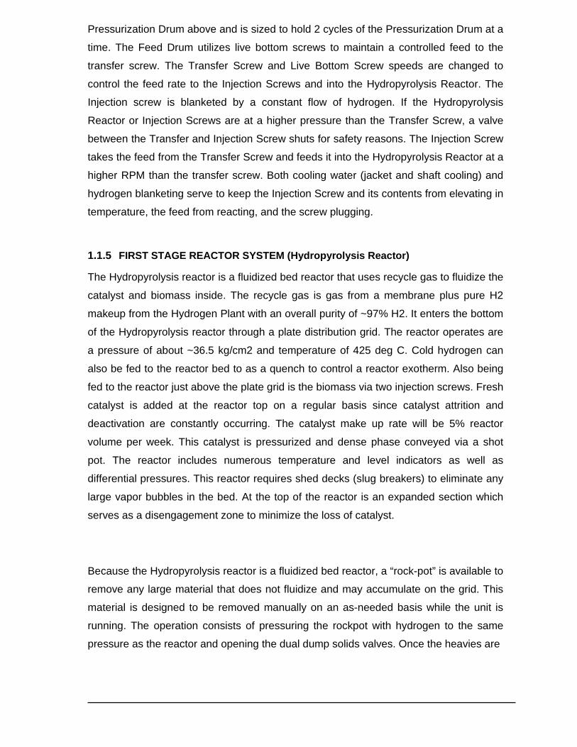
Pressurization Drum above and is sized to hold 2 cycles of the Pressurization Drum at a
time. The Feed Drum utilizes live bottom screws to maintain a controlled feed to the
transfer screw. The Transfer Screw and Live Bottom Screw speeds are changed to
control the feed rate to the Injection Screws and into the Hydropyrolysis Reactor. The
Injection screw is blanketed by a constant flow of hydrogen. If the Hydropyrolysis
Reactor or Injection Screws are at a higher pressure than the Transfer Screw, a valve
between the Transfer and Injection Screw shuts for safety reasons. The Injection Screw
takes the feed from the Transfer Screw and feeds it into the Hydropyrolysis Reactor at a
higher RPM than the transfer screw. Both cooling water (jacket and shaft cooling) and
hydrogen blanketing serve to keep the Injection Screw and its contents from elevating in
temperature, the feed from reacting, and the screw plugging.
1.1.5 FIRST STAGE REACTOR SYSTEM (Hydropyrolysis Reactor) The Hydropyrolysis reactor is a fluidized bed reactor that uses recycle gas to fluidize the
catalyst and biomass inside. The recycle gas is gas from a membrane plus pure H2
makeup from the Hydrogen Plant with an overall purity of ~97% H2. It enters the bottom
of the Hydropyrolysis reactor through a plate distribution grid. The reactor operates are
a pressure of about ~36.5 kg/cm2 and temperature of 425 deg C. Cold hydrogen can
also be fed to the reactor bed to as a quench to control a reactor exotherm. Also being
fed to the reactor just above the plate grid is the biomass via two injection screws. Fresh
catalyst is added at the reactor top on a regular basis since catalyst attrition and
deactivation are constantly occurring. The catalyst make up rate will be 5% reactor
volume per week. This catalyst is pressurized and dense phase conveyed via a shot
pot. The reactor includes numerous temperature and level indicators as well as
differential pressures. This reactor requires shed decks (slug breakers) to eliminate any
large vapor bubbles in the bed. At the top of the reactor is an expanded section which
serves as a disengagement zone to minimize the loss of catalyst.
Because the Hydropyrolysis reactor is a fluidized bed reactor, a “rock-pot” is available to
remove any large material that does not fluidize and may accumulate on the grid. This
material is designed to be removed manually on an as-needed basis while the unit is
running. The operation consists of pressuring the rockpot with hydrogen to the same
pressure as the reactor and opening the dual dump solids valves. Once the heavies are
dumped these valves are shut, the rockpot cooled (it is a jacketed vessel with cooling
water), depressured, purged with inert CO2, and then dumped to a final drum. There is
also the ability to purge the opening in the bottom of the reactor to keep the material
from blocking the opening. There is also a second rockpot at a takeoff at 50% of the
normal reactor level. This would be used if char accumulation occurs.
1.1.6 CYCLONE / SOLIDS CAPTURE SYSTEM
The reactor effluent leaves the top of the reactor and contains the reactor products,
char, ash, and a small amount of catalyst fines. This material travels to the first stage
cyclone where the majority of the solids are removed and stored in the Solids Holding
Drum. The reactor effluent and the remaining solids then go to the second stage
cyclone which is housed in a separate vessel in order to seal the gas from having back
flow between the stages. The solids out of each cyclone will continuously fill both Solids
Holding Drums that contain the cyclones before the solids are transferred out of the
process into the Char Depressurizing system.
99.99% + of the solids are removed from the reactor effluent vapor stream by the
cyclones. After the cyclones, the stream goes to the Hydrotreating Guard Bed where
any remaining solids are trapped to protect the Hydroconversion Reactor from high
pressure drop buildup over the course of the run. The Guard Bed can be changed out
as needed during normal operation when it fills up with fines.
1.1.7 SECOND STAGE REACTOR SYSTEM (Hydroconversion Reactor)
After the guard bed, the effluent goes to the First Stage Reactor Effluent Hot Oil Heater
which cools the vapor stream down to the desired Hydroconversion Reactor inlet
temperature (~295 deg C). The vapor stream then goes to the Hydroconversion Reactor which is a fixed bed
reactor in vapor phase operation. The reactor consists of two beds with a quench in
between the beds. It has numerous temperature indicators and a differential pressure
indicator to measure the reactor pressure drop. This reactor primarily converts any
nitrogen to ammonia and sulfur to hydrogen sulfide and completes the de-oxygenation
reaction.
The reactor effluent then cools down through exchangers that heat the hot oil and hot
water services. After this, the material is cooled the rest of the way with cooling water
and then sent to a three phase separator. From the drum, the mixed hydrocarbon gas
goes to Unit 03 for gas cleanup, the hydrocarbon liquid goes to Unit 04 for third stage
reactor feed preparation, and the water goes to the Sour Water Degassing Drum at
Unit-08.
1.1.8 CHAR DEPRESSURIZING SYSTEM
On 30 minute cycles, the first Solids Holding Drum will transfer the accumulated solids
into the Char Balancing Drum. The Secondary Solids Holding Drum will transfer its
solids on a manual basis as level in the drum dictates. All char handling drums use a
live bottom/transfer screw system to ensure the char material flows from one vessel to
the next. Steam is injected when the dumping occurs in order to minimize product loss. The Char Balancing Drum will be pressurized with inerts to minimize the pressure
difference when the dumping occurs in order to minimize erosion.
The Solids Holding Drum will always maintain a solids seal in order to minimize
hydrogen and products going to the Char Balancing Drum. This drum will be isolated
once the solids are in the Char Balancing Drum. Isolation is achieved between all solids
drums by using two specialty valves in series with a bleeder valve that is pressurized
with inert gas or vented to flare in order to minimize leakage. After the isolation occurs,
this drum is equalized in pressure with the Depressurizing Drum. The solids are then
transferred via live bottom screw(s) from the Char Balancing Drum to the
Depressurizing Drum and then these two drums are isolated from each other. Again,
steam is injected in order to minimize any loss of products.
The Depressurizing Drum is then depressurized thru the Depressurizing Filter which sits
on top of the drum to the CO2 Surge Drum and then finally to the Char Boiler. Any
solids that carry over are captured in the Depressurizing Filter. Recoverable solids from
this filter are backpulsed to the Depressurizing Drum. The Depressurizing Drum and the
Depressurizing Filter are then purged with inerts to the boiler again to remove any
remaining flammable gases from the process. While the Depressurizing Drum is being
purged and emptied of solids, the Char Balancing drum is being pressured up with
inerts for the start of the next cycle.

The CO2 Surge Drum is used to keep the rate of gas being sent to the Char Boiler
relatively constant. There are four steps to the operation of this drum. These are: 1. Depressurizing of the Depressurizing Drum with the flow split between the surge
drum and the Char Boiler. The rate to the boiler is set constant while the rate to the
surge drum starts high and decreases to the constant rate of the boiler. 2. In the second step, the flow is shut off to the surge drum and all the gas goes
directly to the boiler from the depressurizing drum starting at the rate in step
one and decreasing close to zero when the Depressurizing Drum is close to
atmospheric. 3. In the third phase, CO2 is used to purge the char in the Depressurizing Drum to
remove any residual volatiles. This rate is constant and is equal to the rate in the
first step. 4. In the final step, the purge is stopped and the surge drum is opened and
depressurized to the boiler.
The char exits the Depressurizing Drum, on a batch basis, by dilute phase transport to
the Char Surge Bin. This bin goes to char cooling screws and then to the Char Boiler.
This bin separates the batch operation of depressurizing the char from the steady state
operation of burning the char. The hot char is conveyed using CO2 from the Char
Transport Blower to the bin where the CO2 is filtered and returned to the blower. Before
the CO2 returns to the blower it goes through hot and cooling water exchangers where
it is cooled.
The char leaves the Char Surge Bin feeds via the live bottom /transfer screw. Next is
the cooling screw. This screw has cooling water going through the annular area as well
as the housing jackets. The cooled char is then sent to the Char Passivating Screw.
Here the char is sent countercurrent against a mixture of air and inerts to minimize
oxygen concentration. The passivation reaction is exothermic and is further cooled with
the cooling water going through the screw in the same two locations as above. The
oxygen gets consumed in this screw. This exiting gas stream, which is now all inerts, is
filtered with a backpulse filter.
From the passivation screws, the cooled and passivated char is fed via dilute phase
transport to the Char Storage Bin by the Char Transport Blower. The Char Storage Bin
\ then goes to the Char Boiler in Unit 20 for steam production for the Turbo-Generator.
1.1.9 FUEL GAS TREATMENT- UNIT 03 The gas from the Unit 02 separator joins vapor streams from the Liquid HDS separator
and the Depropanizer both in Unit 04 and any LPG required for hydrogen production.
The vapor streams contain H2S which is partially removed by Sulfur Reduction
chemicals injected via a quill. An aqueous solution of water and sulfate is removed in
another separator. The water is sent to the Waste Water Treatment Plant, Unit 24. The
final vapor stream has over 90% of the H2S removed leaving just enough for proper
activation of the Vapor HDS catalyst.
This vapor stream then goes to the HDS-LTS Reactor Feed-Effluent Exchanger and
then to the Hot Oil Vapor HDS Feed Heater which is used to set the reactor temperature
for the Vapor HDS Reactor. This reactor converts organic sulfur to H2S. From there, it
goes to ZnO beds where the H2S is removed. Water is then added in the form of boiler
feed water and high pressure steam before going to the Low Temperature Shift (LTS)
Reactor. The water serves to cool the temperature down to the LTS inlet temperature.
In this reactor, the CO is converted to CO2 to minimize the CO going to the Hydrogen
Plant. It also makes hydrogen thereby decreasing the Hydrogen Plant size. From the
LTS reactor, the material goes through the combined feed exchanger for cooling. This
material then goes through a hot water exchanger, a cooling water exchanger, and to
another separator. Any hydrocarbon liquid from this separator goes to the HDS Stripper
in unit 04. The water goes to the Waste Water Treatment Plant, Unit 24.
The gas is then sent to the Fuel Gas CO2 Amine Contactor where the CO2 is removed.
After this, the gas goes to a two stage Membrane Unit where the hydrogen is recovered
and purified into permeate streams before finally being compressed in the Recycle
Compressor and then sent back to Hydrogen Distribution system in Unit 07 as recycle
gas. The first stage of the membrane concentrates the heavier hydrocarbons and any
KO liquid is sent to the Vapor Splitter.
The hydrocarbon gas stream or resid is also sent to the Vapor Splitter to recover any
Petrol/Gasoline compounds (C4+ material) in the overhead as needed to make
Petrol/Gasoline RVP before it becomes feed to the Hydrogen Plant, Unit 07. The
overhead has a cooler and then a chiller to condense the overhead material since it is
very light material. The tower bottoms goes to the HDS Stripper.
1.1.10 LIQUID HDS -UNIT 04 The Liquid HDS gets its feed from the Unit 02 separator. This reactor section of this unit
consists of a combined feed exchanger, a reactor to convert sulfur to H2S and effluent
cooling. The combined feed of the liquid and hydrogen is heated up with a hot oil.
Hydrogen is cascaded from the Aromatic Saturation Unit 05 separator although if that
unit is down it can come from the Unit 07 Hydrogen Distribution system directly. Hot
water is also made in the reactor effluent cooling system. Liquid is recycled from the
separator to minimize the reactor delta temperature. The separator liquid goes to the
HDS Stripper. The separator gas goes back to the Vapor HDS reactor in Unit 03. There are four columns in the fractionation section in this unit. These are the HDS
Stripper, Depropanizer, Primary Fractionator, and the Benzene Splitter. The HDS
Stripper Column gets feed from this unit as well as the light naphtha returning from the
Vapor Splitter located in Unit 03. The HDS Stripper runs at low pressure and uses hot
oil for reboiling to strip most of the pentane and lighter material out the top of the tower
(almost all of the benzene remains in the bottoms product). The bottoms are sent to the
Primary Fractionator. The Stripper Overhead Gas is sent to the recycle gas compressor.
The liquid from the overhead drum is sent to the Depropanizer tower.
The Depropanizer Column runs at a higher pressure and separates the sour light ends
(C3 minus) from the butane to hexane cut material. This tower is reboiled with hot oil.
The Overhead Gas and Liquid are sent back to the Vapor HDS Unit 03 to remove any
H2S with the Sulfur Reduction Chemicals System. The tower bottoms material is sent
as a Petrol/Gasoline product.
As mentioned before, the HDS Stripper bottoms material goes to the Primary
Fractionator which runs at low pressure and uses LP Steam to strip the Naphtha from
the Diesel. The diesel material is sent to Unit 05 to be saturated. The overhead naphtha
material goes to the Benzene Splitter Column.
The Benzene Splitter runs at low pressure and is reboiled by low pressure steam. The
target is to make a bottoms material which is a heavy naphtha stream containing less
than the maximum amount of benzene material that is allowed in the finished
Petrol/Gasoline product. This material is sent straight to Petrol/Gasoline. The Benzene
Splitter overhead material contains the rest of the benzene and lighter compounds and
goes to Unit 05 to be saturated.
1.1.11 AROMATIC SATURATION- UNIT 05 The CO2 rich off gas from the process is sent to the two Amine Contactors in Units 03
and 07. Lean amine from this unit feeds these two contactors and absorbs the CO2.
The rich amine from the bottom of these contactors combines and is flashed in the rich
amine flash drum. Some light hydrocarbon and CO2 material is flashed, scrubbed in the
vapor outlet line and used as fuel gas for the hydrogen plant via an ejector. The rich
amine outlet from the flash drum is pumped to the amine regenerator via the lean/rich
exchanger on flow control.
The rich amine is stripped of CO2 in the regenerator tower using an LP steam reboiler.
The overhead is condensed with an acid gas vapor product being recovered. It is
important to note that unlike a lot of Amine units, this acid gas contains no H2S. The
overhead liquid is returned to the tower as reflux. Should the amine concentration drop
in the system, water can be removed from the overhead system to return to the desired
concentration. Conversely, if the activated MDEA concentration drops, MDEA or the
active agent can be added. The stripped lean amine from the bottom of the tower is
cooled in the lean/rich exchanger and pumped back to the amine contactors. A slip
stream of lean amine will be filtered to remove particulates and other impurities to keep
the amine clean and minimize the amine foaming tendencies.
Provisions for storing make up amine and amine system inventory are provided. The
lean amine is MDEA with an activating agent (called activated amine) and allows for
higher recovery of CO2. The CO2 rich off gas from the regenerator is dried and
compressed for use in the inert gas system.
An inert gas system is required for the purging of the feed and char handling systems
and pressuring of the char system. The inert gas source will be CO2 from the Amine
Unit Regenerator overhead. The inert gas from the amine unit will be compressed with
an inert gas compressor and dried. Some of the inert gas will then be used at low
pressure. The remaining gas will be compressed to a higher pressure and used in the
Char System for repressuring.
1.1.12 HYDROGEN PLANT- UNIT 07
The Hydrogen Plant feed comes from the Vapor Splitter column in Unit 03 and will be
converted in the steam methane reformer into hydrogen. Any excess feed will be used
as the fuel gas to fire the reformer furnace. If more feed is required to make hydrogen,
LPG can be sent to front of Unit 03. This gas will eventually make its way to the
Hydrogen Plant.
For this project the core hydrogen plant components are being provided by a licensed
vendor. The vendor will be responsible for creating hydrogen syngas that will be sent to
an Amine contactor tower. This contactor is utilized to recover the CO2 which will be
sent to the Amine Unit 06 and used as a source of inert gas. They will also be
responsible from final clean up of the hydrogen syngas via a pressure swing absorption
(PSA) unit. The hydrogen plant requires steam which will be generated in the vendor
package. Demineralized water will be provided to the package and high pressure steam
and boiler blowdown will be additional export streams of the package.
The Hydrogen Distribution system heats, cools, and distributes the hydrogen to a
variety of locations. The main location is the Hydropyrolysis reactor. Another portion
which is cooled is sent to the Feed Screws and as quenches to the Hydropyrolysis and
Hydroconversion reactors if needed. Uncooled hydrogen can be also sent to the
Aromatic Saturation Reactor. It can also go to the liquid phase HDS reactor for startup
or when the Saturation Unit is down. The gas can be also heated via high pressure
steam and then by the Hydrogen Gas Feed Heater for startup or if needed during
normal operation. However, the gas normally is only heated by the heat exchange
before going to the Hydropyrolysis reactor. It is also used as makeup for the Hydrogen
Pressurization System.
1.1.12.1 SOUR WATER STRIPPER- UNIT 08 Water is introduced into the process in multiple ways. It evolves from the moisture in the
wood feeding the unit, it is generated in the IH2® Reactors, and it is added as steam
and/or boiler feed water injection points throughout different stages in the process.
Almost all of this water is captured in knockout drums, overhead water boots, and three
phase separators and contains ammonia, carbon dioxide, and a small amount of H2S.
This water is collected in a header before being sent to the Sour Water Stripping Unit.
This water must be treated in a Sour Water Stripper Unit to remove the NH3, CO2, and
H2S. The Sour Water Stripping Unit will consist of a degassing drum and associated
pumps, sour water feed tank with associated pumps, a feed/effluent exchanger, a sour
water stripper tower, steam reboiler, and stripped water cooler. The NH3, CO2 and a
small amount of H2S are stripped out in the stripper tower. The stripped sour water from
the bottom of the stripper tower is cooled and sent to the cooling tower in Unit 20.
The overhead acid gas stream containing NH3, CO2, and H2S goes to the Char Boiler.
1.1.13.1 UTILITIES PLANTS- UNIT 20
1.1.13.2 Raw Water System The water used to meet the plant demands is supplied from well pumps. The Tube Well
water is collected in feed collection tanks. Raw water from feed collection tank will be
routed to Degasser tower filled with PP raschig rings and Air is forced from the bottom
of the tower by Centrifugal Blowers, while the water flows down through the packed bed
of PP rings. The carbonic acid present in the water splits up into carbon dioxide gas and
water. This carbon dioxide gas is stripped off and escapes from the top of the tower.
The degassed water is collected in the degassed water tank and is pumped to Basket
Strainers & Ultra filtration. This filter is a guard filter for ultrafiltration system.
Filtered water is routed to Ultra filtration system to maintain SDI (Silt Density Index) <3
which is necessary to maintain at inlet of RO system to safe guard membranes. Ultra
filtration is a membrane process in which a porous membrane is used to separate or
reject colloidal and particulate matter. Water is pressurized through the membrane and
particulates are left at membrane surface. Due to small pore size of the membrane,
effectively all suspended solids are removed from the filtrate.
The modes of operation of Ultrafiltration are: Processing, Backwash and Cleaning
System is automated to switch between these modes. However, cleaning and integrity
testing modes is manual.
UF treated effluent will be processed through cartridge filters which will be used as
pretreatment step before RO-I system to safeguard RO-I membranes. Micron cartridge
filter is provided in order to remove micron size particles, which are not removed by the
sand filter. These Cartridges are disposable type and should be replaced if differential
pressure across cartridges approaches pre-specified level.
Processed effluent from cartridge filters will be route d to RO-I system to process the
FEED water and remove TDS, & Silica to the extent as desirable. Reject from RO-I will
be stored in reject disposal tank. Reject shall be used for Horticulture purpose with
TDS<2100 PPM The recovery from RO-I shall be 80%. Permeate water from RO will be
stored in storage tank from where it will be pumped to Mixed Bed Exchanger for final
polishing and for DM water production.
Permeate water from RO will be stored in storage tank from where it will be pumped to
Mixed Bed Exchanger for final polishing and for DM water production. MB unit has both
Strong Acid Cation Resin and Strong Base Anion resin mixed in a single vessel. The
regeneration of these resins is carried out in simultaneous regeneration, i.e. cation by
Hydrochloric Acid in countercurrent and anion by caustic in co-current. The MB bed
exchanger functions as multiple cycles of cation and anion exchanges and thus polishes
the water to best extent possible.
1.1.13.3 Potable Water system The potable water system is supplied by water after it passes through the Ultrafiltration.
It is stored in the potable water tank and pumped to users. A small recycle stream is
drawn from the pump supply, treated with chlorine, and returned to the potable water
tank.
1.1.13.4 BOILER FEED WATER PREPARATION Service water requires further treatment before being used for steam generation. First it
is treated in an ion exchange demineralization unit to further reduce the hardness.
Backwash from the unit is sent to the cooling tower while acidic/basic liquid used in
regeneration is neutralized and sent to waste water treatment. The water is collected in
a demineralized water storage tank and then pumped, as needed, to a deaerating unit.
The deaerating unit removes any dissolved gasses and brings the water to boiler feed
quality.
1.1.13.5 STEAM/CONDENSATE/POWER GENERATION Superheated high pressure steam (~80 kg/cm2) is produced by the Char Boiler and
auxiliary boiler(s). High pressure steam is created in the Hydrogen Plant. Low pressure
steam is produced as a side stream from the turbo generator. The superheated high pressure steam is used to generate electricity via a turbo
generator. A side draw is used to supply the rest of the plant with low pressure steam.
As the low pressure steam has a slight super heat it is saturated using a desuperheater
before entering into the low pressure steam header. The outlet of the generator goes to
a surface condenser which condenses all of the steam and sends it to the low pressure
condensate system. Additional desuperheater capacity is provided to break down
superheated high pressure stream and high pressure stream as needed to supply the
low pressure steam header, if required.
The char from unit 02 is sent to a surge bin equipped with live bottom screws. The feed
screws will discharge to the “in-bed” feeder system furnished by the fluid bed boiler
supplier. The char will be injected below the surface of the fluidized bed after the bed
material is brought up to temperature using LPG.
LPG will be used to warm the bed and to maintain a minimum bed temperature until the
char flow and combustion is able to sustain it. LPG will also be used as supplemental
fuel when the fuel demand exceeds the available char.
Accessories and emission controls include a proprietary bed media cleaning and re-
injection system, bed media storage, FD and ID fans, access stairs and platforms,
economizer, SNCR and SCR for NOx control, limestone injections for SOx control,
baghouse, stack, CEMS and ash collection systems.
1.1.13.6 COOLING WATER SYSTEM
The cooling water system consists of a closed loop cooling water circuit with a cooling
tower. Makeup water is taken from the outlet of the lime softening unit, the stripped sour
water, boiler blowdowns, and demineralized water backwash.

1.1.13.7 CHILLED WATER SYSTEM The chilled water system uses an adsorption process to supply the plant with chilled
water. Gas is adsorbed and desorbed in order to chill a water stream. Cooling water is
used to adsorb a refrigerant, cooling the chilled water. The hot water is used to
regenerate the adsorbent.
1.1.13.8 HOT WATER SYSTEM
The hot water system supplies low level heat to dry biomass of the plant (Refer unit-01).
It gets it heat from various waste heat locations in the process with the majority from the
reactor effluent in Unit 02. After coming from the process, the water is further heated by
low pressure steam, if needed, to get to the required temperature of 120 C. After being
used to dry biomass, the cooled hot water is returned back to the process. A portion of
the water will be sent to a separator that will provide surge/thermal expansion capacity
and also allow any oil that enters the system via leaks to be skimmed off and removed
from the system. An air cooler is used to handle unbalanced heat loads and emergency
cooling if dryer operation is shut down.
1.1.13.9 HOT OIL SYSTEM The hot oil system is a closed loop system. The hot oil is pumped to equipment that
requires cooling, which heats the oil, and then to heat exchangers that require heat
inputs, cooling the oil. The Hydropyrolysis and Hydroconversion Reactor effluents utilize
the hot oil loop for cooling and the Hot Oil Heater (H-2055) provides supplementary heat
to reach the required temperature. The heated oil is then used in eight heat exchangers
to supply heat to the system.
1.1.13.10 INSTRUMENT AIR/PLANT AIR/NITROGEN
The instrument/plant air system will be supplied by air from two air compressor skids.
The two compressors will discharge to a common air receiver. The plant air will come
directly from the air receiver, but the instrument air will meet the moisture dew point
requirement by passing through a dryer before entering the instrument air header. Nitrogen shall be sourced from outside in industrial cylinders. 2 days equivalent nitrogen
storage in the form of industrial cylinders is recommended.
1.1.13.11 FLARE FLARE SYSTEM EQUIPMENTS
The plant will have one flare to handle all relief loads. The flare system will include the
following items:
1) Flare header
2) Flare knock out drum (D-2070)
3) Flare knock out drum pumps (P-2070 A/B & P-2071A/B)
4) Flare Stack (ML-2070) and Flare Tip (The flare tip pilots will be lit with LPG). ROUTING OF PRODUCT FROM FLARE KNOCK OUT DRUM The product from flare knock out drum is routed to off spec tank (Unit-21) and to sour
water header (Unit-08) using dedicated pumps (P-2070 A/B & P-2071A/B respectively).
The flare drum has an over flow weir so that water can be separated from liquid
hydrocarbon and recycled accordingly.
1.1.13.12 FUEL GAS SYSTEM The fuel gas system has a Fuel Gas Balance Tank that is the destination for gas from
the Saturator Reactor Feed Surge Drum and the Secondary Fractionator Overhead
Drum. The pressure is controlled by adding LPG as needed. The balance tank gas goes
to various destinations throughout the plant where fuel gas is required.
1.1.14 TANKS AND PUMPS- UNIT 21
1.1.14.1 FINISHED PRODUCTS STORAGE
Finished products are received in day tanks which are subsequently transferred to
product storage tanks. The system for the naphtha and diesel products consists of two
day tank for each product namely TK-2100/2101 & TK-2110/2111. Each product system
will have transfer pumps (1W+1S) to move the product from the day tanks to product
tanks. The product tanks have the capacity to have 7 days storage.
1.1.14.2 PRODUCT DISPATCH
The products are dispatched using trucks. Truck loading stations are included to fill
truck with Petrol/Gasoline and diesel products. Dedicated bays along with product
transfer pumps (1W+1S) and metering assembly are provided.
1.1.14.3 OFF-SPEC PRODUCT STORAGE TANKS
Off spec product tank and associated pumps will be provided to allow the rerunning or
selling of the off spec product. The naphtha and the off spec tanks will be equipped with
floating roofs.
1.1.14.4 ETHANOL BLENDING
Facility for ethanol blending is also provided so as to have 10% ethanol blended
Petrol/Gasoline. An ethanol tank along with pumps P-2102A/B (1W+1S) is included to
blend ethanol into the finished Petrol/Gasoline for the same. Ethanol is received via
road trucks and is stored in ethanol storage tank.
1.1.14.5 INTERMEDIATE PRODUCT STORAGE & TRANSFER SYSTEM
Intermediate tankage is provided for sweet and sour products. The sour tankage will be
used if the liquid HDS unit is down while the sweet tankage is required for a shutdown
of the Aromatic Saturation unit. The products from intermediate storage tanks are
routed to Liquid Hydrotreater unit (04) & Aromatic Saturation Unit (05) respectively.
1.1.14.6 OTHER STORAGE The facility requires LPG which will be supplied by truck. LPG truck unloading facilities
as well as LPG storage in the form of bullets is provided. Two LPG storage bullets are
provided each of capacity 1000 cu m. Vaporized LPG is supplied to the plant via LPG
pump and LPG vaporizer (E-2142) utilizing LP steam for heating.
1.1.14 WASTE WATER TREATMENT PLANT- UNIT 24 Waste water from Oily water sewer, cooling tower blow downs, Brine from diesel dryers,
Water from contact sewer are routed to TPI Separators to remove the free oil and
suspended solids. Free oil (Dia.>60m) present in the above streams is removed with the
help of density difference between the dispersed phase (oil) and the dispersion medium
(water). In order to provide effective surface area, numbers of inclined oleophilic plates
are provided. To achieve this Tilted Plate Interceptors (TPI) system is envisaged. Due to the possibility of VOC emissions, both the units shall be covered and provided
with suitable vents connected to VOC handling system, safety system and access. To
skim the free oil from the surface, slotted pipe skimmer shall be provided. Sludge
settled at the bottom shall be scrapped off through the sludge pit.
In addition to the contact retention pond there is also a non-contact pond. Area drains
from non-process parts of the site flow into the non-contact pond. The run off is retained
in the pond for testing to ensure compliance with environmental regulations for
discharge. If the testing fails to meet regulations the pond water can be metered into the
wastewater treatment package. All retention ponds can be pumped directly to
environmental discharge in an emergency event where storm water rates are higher
than design. The FEL-2 assumption is that the ponds are large enough to contain any
fire water event which is not expected to occur at the same time as a major storm event.
After pH adjustment, the oil free effluents to be pumped to the biological treatment unit,
the Sequencing Batch Reactor to remove BOD along with corresponding COD,
Ammonia, Residual Sulfides and Phenols, Phosphorus etc. Effluent equalization shall
be of a part of the Sequential Batch Reactor. The Sequential Batch process shall be
well proven for this type of effluent and shall have high end outlet performance. The
sequencing batch reactor shall perform Nitrification, Denitrification, and control of
phosphorus. The reactors shall be installed in such a way that they allow continuous
operation with continuous influent and discharge. It shall be capable of simultaneous
sludge stabilization. The oxygen required shall be through diffused aeration system with
intelligent control of oxygen level in the tank. The system shall be designed in such a
way that growth of filamentous bacteria is suppressed and high settling rate of sludge is
achieved. SVI < 120 shall be achieved in the process. All the recycling of effluent,
monitoring of critical data, oxygen level in the tank and decanting shall be through PLC
based control system. Minimum three Nos. of tanks shall be provided based on the
process requirement.
Biological Sludge generated shall be routed to Sludge handling section comprises
handling of various types of sludges generated through the treatment, viz., Oily &
Chemical sludges and Bio sludges, with sludge thickening, mechanical de-watering, oily
sludge confined bioremediation, etc.
A Package Treatment Plant has been envisaged to treat Sanitary Effluent & Canteen
Waste. Sanitary Effluent shall be treated in the Sanitary Treatment Unit to meet all the
Statutory Discharge norms and the final Effluent shall be treated and used for
horticulture.