Embed Size (px)
Citation preview

PHYSICAL REVIEW E 84, 061601 (2011)
Elastocapillary instability under partial wetting conditions: Bending versus buckling
Bruno Andreotti,1 Antonin Marchand,1 Siddhartha Das,2 and Jacco H. Snoeijer2
1Physique et Mecanique des Milieux Heterogenes, UMR 7636 ESPCI -CNRS, Universite Paris-Diderot,10 rue Vauquelin, F-75005 Paris, France
2Physics of Fluids Group and J. M. Burgers Centre for Fluid Dynamics, University of Twente, P.O. Box 217,NL-7500 AE Enschede, The Netherlands
(Received 14 September 2011; published 1 December 2011)
The elastocapillary instability of a flexible plate plunged in a liquid bath is analyzed theoretically. We showthat the plate can bend due to two separate destabilizing mechanisms, when the liquid is partially wetting thesolid. For contact angles θe > π/2, the capillary forces acting tangential to the surface are compressing theplate and can induce a classical buckling instability. However, a second mechanism appears due to capillaryforces normal to surface. These induce a destabilizing torque that tends to bend the plate for any value of thecontact angle θe > 0. We denote these mechanisms as “buckling” and “bending,” respectively and identify thetwo corresponding dimensionless parameters that govern the elastocapillary stability. The onset of instabilityis determined analytically and the different bifurcation scenarios are worked out for experimentally relevantconditions.
DOI: 10.1103/PhysRevE.84.061601 PACS number(s): 68.03.−g, 46.32.+x
I. INTRODUCTION
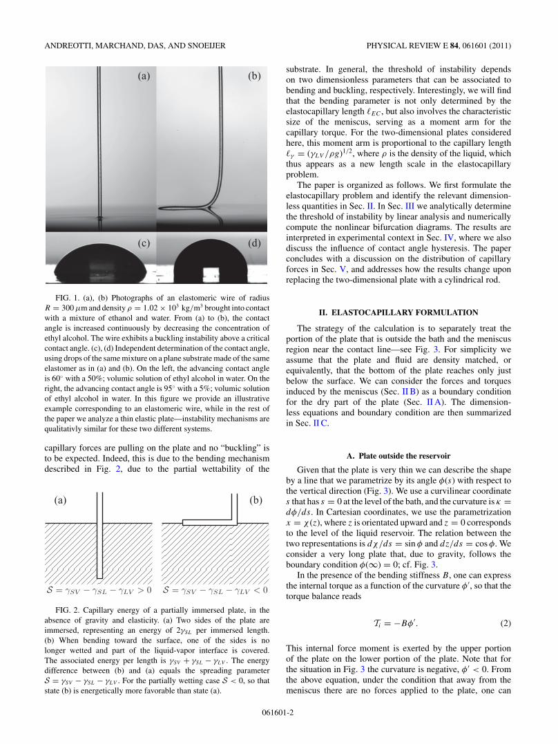
Water-walking arthropods like water striders are able tofloat, despite their density, thanks to surface tension forces [1].Their superhydrophobic legs are submitted to a repulsive forcealong the contact line where the three phases (liquid, vapor,and solid) meet. As the legs are long and flexible, they deformunder these capillary forces [2]. Figure 1 shows an experimentperformed with extremely slender artificial legs made of a softsolid, which is plunged into a liquid bath. One observes anelastocapillary instability that is triggered by increasing thecontact angle θe: the initially immersed solid is pushed out ofthe liquid to the free surface, whenever θe is sufficiently large.
In the limiting case of complete wetting, i.e., θe = 0,a compressive force is exerted on an elastic rod initiallyimmersed in a liquid when its end pierces the liquid interface[3–5]. Such a rod buckles when the compressive force exceedsEuler’s critical load. Consider the case of a plate of thicknessH much smaller than its length L and its width W . It issubmitted to a capillary force equal to the water surface tensionγLV times the perimeter �2W . The critical force is equal to(π/2)2BW/L2, where B is the bending stiffness, which canbe expressed as B = EI/W (1 − ν2), where E is the Young’smodulus, ν the Poisson ratio, I the moment of inertia and W
the width of the plate. Therefore buckling occurs if the plateis longer than a critical length Lcr = (π/2)
√B/(2γLV ). It is
proportional to the elastocapillary length
�EC =(
B
γLV
)1/2
, (1)
which is the length scale controlling a large class of elastocap-illary problems [4–12].
One may wonder if the instability observed in Fig. 1is of the same physical nature. Indeed, one can expect abuckling instability if the contact angle θe is larger thanπ/2. Namely, the total downward force that the reservoirexerts on the solid is proportional to γLV cos θe, and hencechanges from “stretching” to “compressing” when the contactangle exceeds π/2. However, there is a second mechanism
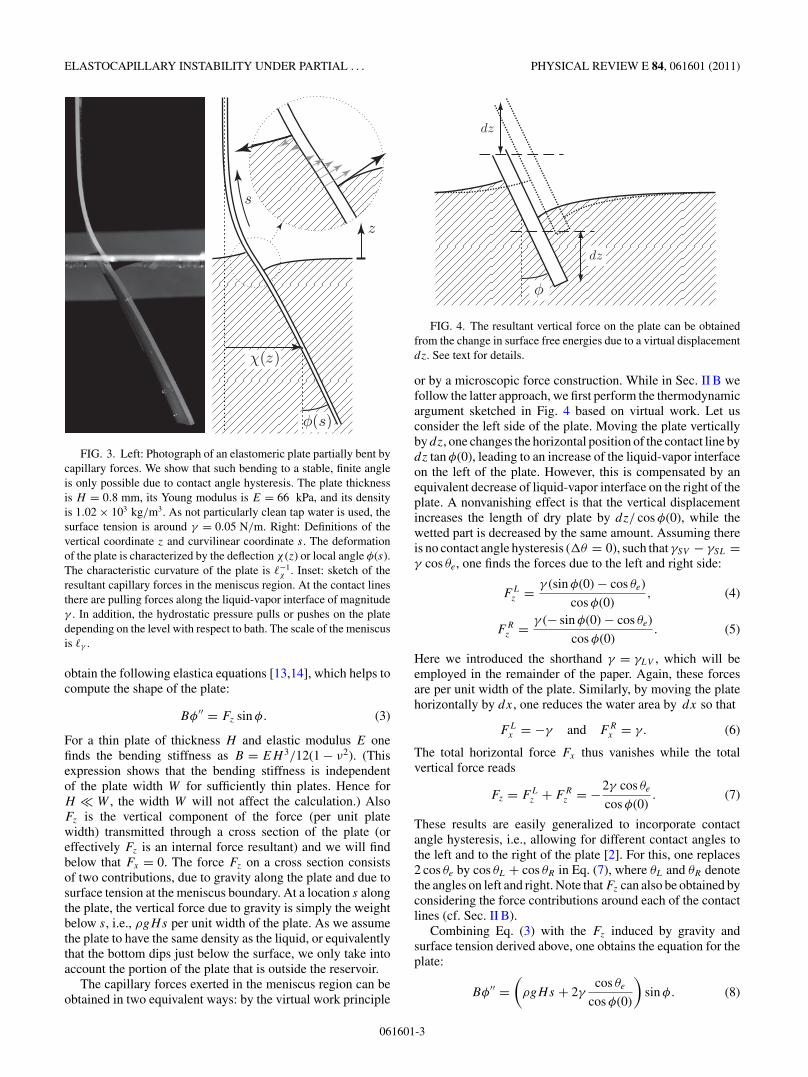
that can lead to elastic deformations. Figure 2 compares thecapillary energy of an extremely flexible object that eitherremains vertical or floats on the free surface of the liquid.The free energy difference is proportional to the spreadingparameter S = γSV − γSL − γLV , where γSV , γSL, and γLV
are, respectively, the surface tensions of the solid-vapor,solid-liquid, and liquid-vapor interfaces. As a consequence,bending is favorable under partial wetting conditions, S < 0,whatever the value of the contact angle θe. This is manifestlydifferent from the buckling instability, which can only occurfor θe > π/2. Indeed, the mechanism for instability is not thevertically compressing force, but is a bending induced by thecapillary torque exerted near the contact line [2].
In this paper we investigate theoretically the instability of atwo-dimensional, elastic plate plunged in a liquid of the samedensity. In light of former studies, we wish to address differentissues. What are the mechanisms for instability: bending,buckling, or a combination of the two? What is the relevantlength L for the instability in the situation of Fig. 1, where theplate can be supposed to be infinite? What are the parameterscontrolling the instability?
To illustrate the two mechanisms of elastocapillary instabil-ity, bending, and buckling, we consider a long elastic plate thatis hanging freely under the influence of gravity. We assumethe thickness to be sufficiently small to allow for a thin plateelastic description. The bottom of the plate is brought intocontact with a liquid reservoir that partially wets the solid,with an equilibrium contact angle θe. To reveal the effect ofsurface wettability, we focus on the case where both sides ofthe plate are wetted by the same angle. This is fundamentallydifferent from the situation prior to piercing of an elastic solidthrough a meniscus [2–5], for which one of the contact lines ispinned to the edge of the solid—in that case the contact anglecan attain any value. Our goal is to compute the shape of theplate and to analytically determine the threshold of instabilityfor different θe.
Our main finding is that the elastocapillary instability canoccur even when θe < π/2, which is the regime where the
061601-11539-3755/2011/84(6)/061601(11) ©2011 American Physical Society
ANDREOTTI, MARCHAND, DAS, AND SNOEIJER PHYSICAL REVIEW E 84, 061601 (2011)
(a)
(c)
(b)
(d)
FIG. 1. (a), (b) Photographs of an elastomeric wire of radiusR = 300 μm and density ρ = 1.02 × 10³ kg/m3 brought into contactwith a mixture of ethanol and water. From (a) to (b), the contactangle is increased continuously by decreasing the concentration ofethyl alcohol. The wire exhibits a buckling instability above a criticalcontact angle. (c), (d) Independent determination of the contact angle,using drops of the same mixture on a plane substrate made of the sameelastomer as in (a) and (b). On the left, the advancing contact angleis 60◦ with a 50%; volumic solution of ethyl alcohol in water. On theright, the advancing contact angle is 95◦ with a 5%; volumic solutionof ethyl alcohol in water. In this figure we provide an illustrativeexample corresponding to an elastomeric wire, while in the rest ofthe paper we analyze a thin elastic plate—instability mechanisms arequalitativly similar for these two different systems.
capillary forces are pulling on the plate and no “buckling” isto be expected. Indeed, this is due to the bending mechanismdescribed in Fig. 2, due to the partial wettability of the
(a) (b)
FIG. 2. Capillary energy of a partially immersed plate, in theabsence of gravity and elasticity. (a) Two sides of the plate areimmersed, representing an energy of 2γSL per immersed length.(b) When bending toward the surface, one of the sides is nolonger wetted and part of the liquid-vapor interface is covered.The associated energy per length is γSV + γSL − γLV . The energydifference between (b) and (a) equals the spreading parameterS = γSV − γSL − γLV . For the partially wetting case S < 0, so thatstate (b) is energetically more favorable than state (a).
substrate. In general, the threshold of instability dependson two dimensionless parameters that can be associated tobending and buckling, respectively. Interestingly, we will findthat the bending parameter is not only determined by theelastocapillary length �EC , but also involves the characteristicsize of the meniscus, serving as a moment arm for thecapillary torque. For the two-dimensional plates consideredhere, this moment arm is proportional to the capillary length�γ = (γLV /ρg)1/2, where ρ is the density of the liquid, whichthus appears as a new length scale in the elastocapillaryproblem.
The paper is organized as follows. We first formulate theelastocapillary problem and identify the relevant dimension-less quantities in Sec. II. In Sec. III we analytically determinethe threshold of instability by linear analysis and numericallycompute the nonlinear bifurcation diagrams. The results areinterpreted in experimental context in Sec. IV, where we alsodiscuss the influence of contact angle hysteresis. The paperconcludes with a discussion on the distribution of capillaryforces in Sec. V, and addresses how the results change uponreplacing the two-dimensional plate with a cylindrical rod.
II. ELASTOCAPILLARY FORMULATION
The strategy of the calculation is to separately treat theportion of the plate that is outside the bath and the meniscusregion near the contact line—see Fig. 3. For simplicity weassume that the plate and fluid are density matched, orequivalently, that the bottom of the plate reaches only justbelow the surface. We can consider the forces and torquesinduced by the meniscus (Sec. II B) as a boundary conditionfor the dry part of the plate (Sec. II A). The dimension-less equations and boundary condition are then summarizedin Sec. II C.
A. Plate outside the reservoir
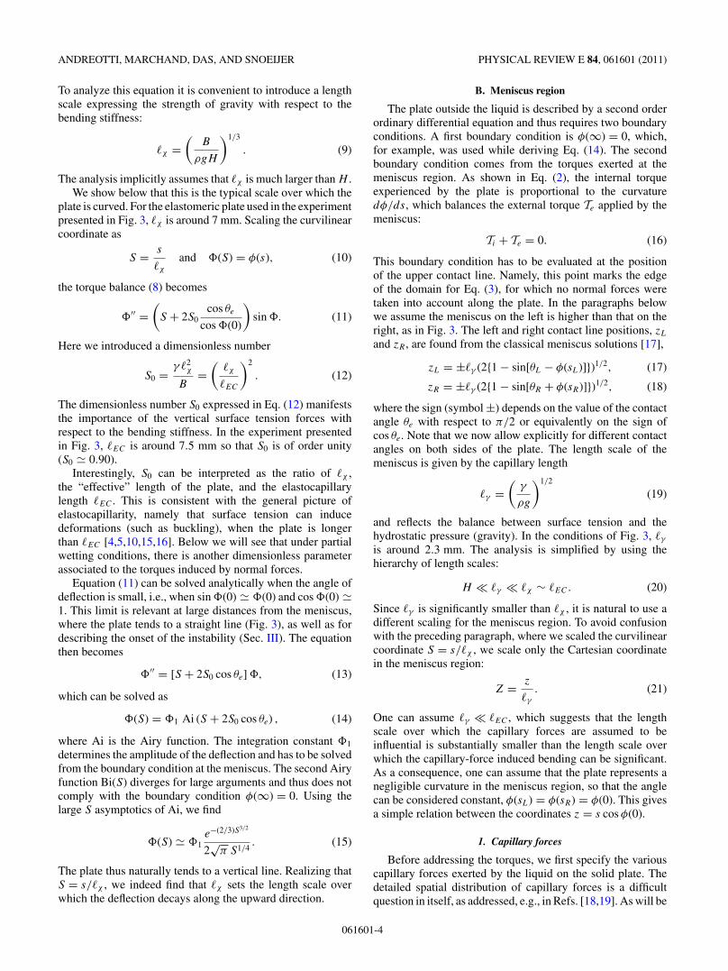
Given that the plate is very thin we can describe the shapeby a line that we parametrize by its angle φ(s) with respect tothe vertical direction (Fig. 3). We use a curvilinear coordinates that has s = 0 at the level of the bath, and the curvature is κ =dφ/ds. In Cartesian coordinates, we use the parametrizationx = χ (z), where z is orientated upward and z = 0 correspondsto the level of the liquid reservoir. The relation between thetwo representations is dχ/ds = sin φ and dz/ds = cos φ. Weconsider a very long plate that, due to gravity, follows theboundary condition φ(∞) = 0; cf. Fig. 3.
In the presence of the bending stiffness B, one can expressthe internal torque as a function of the curvature φ′, so that thetorque balance reads
Ti = −Bφ′. (2)
This internal force moment is exerted by the upper portionof the plate on the lower portion of the plate. Note that forthe situation in Fig. 3 the curvature is negative, φ′ < 0. Fromthe above equation, under the condition that away from themeniscus there are no forces applied to the plate, one can
061601-2
ELASTOCAPILLARY INSTABILITY UNDER PARTIAL . . . PHYSICAL REVIEW E 84, 061601 (2011)
FIG. 3. Left: Photograph of an elastomeric plate partially bent bycapillary forces. We show that such bending to a stable, finite angleis only possible due to contact angle hysteresis. The plate thicknessis H = 0.8 mm, its Young modulus is E = 66 kPa, and its densityis 1.02 × 10³ kg/m3. As not particularly clean tap water is used, thesurface tension is around γ = 0.05 N/m. Right: Definitions of thevertical coordinate z and curvilinear coordinate s. The deformationof the plate is characterized by the deflection χ (z) or local angle φ(s).The characteristic curvature of the plate is �−1
χ . Inset: sketch of theresultant capillary forces in the meniscus region. At the contact linesthere are pulling forces along the liquid-vapor interface of magnitudeγ . In addition, the hydrostatic pressure pulls or pushes on the platedepending on the level with respect to bath. The scale of the meniscusis �γ .
obtain the following elastica equations [13,14], which helps tocompute the shape of the plate:
Bφ′′ = Fz sin φ. (3)
For a thin plate of thickness H and elastic modulus E onefinds the bending stiffness as B = EH 3/12(1 − ν2). (Thisexpression shows that the bending stiffness is independentof the plate width W for sufficiently thin plates. Hence forH � W , the width W will not affect the calculation.) AlsoFz is the vertical component of the force (per unit platewidth) transmitted through a cross section of the plate (oreffectively Fz is an internal force resultant) and we will findbelow that Fx = 0. The force Fz on a cross section consistsof two contributions, due to gravity along the plate and due tosurface tension at the meniscus boundary. At a location s alongthe plate, the vertical force due to gravity is simply the weightbelow s, i.e., ρgHs per unit width of the plate. As we assumethe plate to have the same density as the liquid, or equivalentlythat the bottom dips just below the surface, we only take intoaccount the portion of the plate that is outside the reservoir.
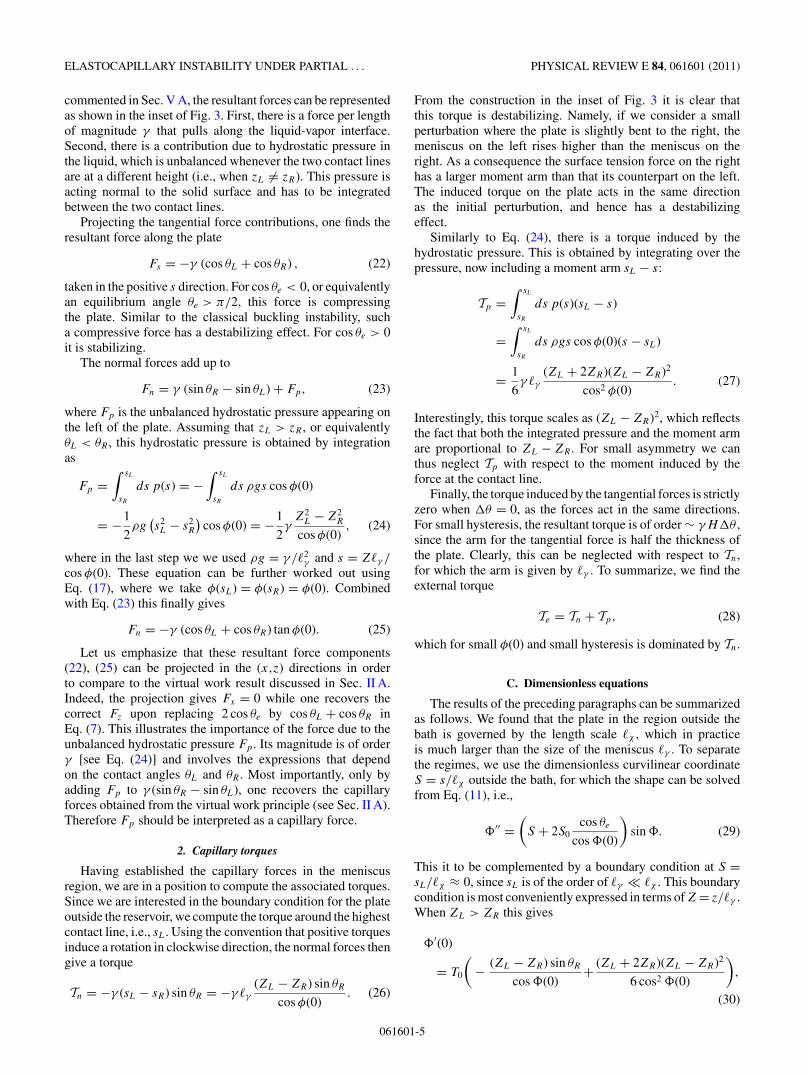
The capillary forces exerted in the meniscus region can beobtained in two equivalent ways: by the virtual work principle
FIG. 4. The resultant vertical force on the plate can be obtainedfrom the change in surface free energies due to a virtual displacementdz. See text for details.
or by a microscopic force construction. While in Sec. II B wefollow the latter approach, we first perform the thermodynamicargument sketched in Fig. 4 based on virtual work. Let usconsider the left side of the plate. Moving the plate verticallyby dz, one changes the horizontal position of the contact line bydz tan φ(0), leading to an increase of the liquid-vapor interfaceon the left of the plate. However, this is compensated by anequivalent decrease of liquid-vapor interface on the right of theplate. A nonvanishing effect is that the vertical displacementincreases the length of dry plate by dz/ cos φ(0), while thewetted part is decreased by the same amount. Assuming thereis no contact angle hysteresis (�θ = 0), such that γSV − γSL =γ cos θe, one finds the forces due to the left and right side:
FLz = γ (sin φ(0) − cos θe)
cos φ(0), (4)
FRz = γ (− sin φ(0) − cos θe)
cos φ(0). (5)
Here we introduced the shorthand γ = γLV , which will beemployed in the remainder of the paper. Again, these forcesare per unit width of the plate. Similarly, by moving the platehorizontally by dx, one reduces the water area by dx so that
FLx = −γ and FR
x = γ. (6)
The total horizontal force Fx thus vanishes while the totalvertical force reads
Fz = FLz + FR
z = −2γ cos θe
cos φ(0). (7)
These results are easily generalized to incorporate contactangle hysteresis, i.e., allowing for different contact angles tothe left and to the right of the plate [2]. For this, one replaces2 cos θe by cos θL + cos θR in Eq. (7), where θL and θR denotethe angles on left and right. Note that Fz can also be obtained byconsidering the force contributions around each of the contactlines (cf. Sec. II B).
Combining Eq. (3) with the Fz induced by gravity andsurface tension derived above, one obtains the equation for theplate:
Bφ′′ =(
ρgHs + 2γcos θe
cos φ(0)
)sin φ. (8)
061601-3
ANDREOTTI, MARCHAND, DAS, AND SNOEIJER PHYSICAL REVIEW E 84, 061601 (2011)
To analyze this equation it is convenient to introduce a lengthscale expressing the strength of gravity with respect to thebending stiffness:
�χ =(
B
ρgH
)1/3
. (9)
The analysis implicitly assumes that �χ is much larger than H .We show below that this is the typical scale over which the
plate is curved. For the elastomeric plate used in the experimentpresented in Fig. 3, �χ is around 7 mm. Scaling the curvilinearcoordinate as
S = s
�χ
and �(S) = φ(s), (10)
the torque balance (8) becomes
�′′ =(
S + 2S0cos θe
cos �(0)
)sin �. (11)
Here we introduced a dimensionless number
S0 = γ �2χ
B=
(�χ
�EC
)2
. (12)
The dimensionless number S0 expressed in Eq. (12) manifeststhe importance of the vertical surface tension forces withrespect to the bending stiffness. In the experiment presentedin Fig. 3, �EC is around 7.5 mm so that S0 is of order unity(S0 � 0.90).
Interestingly, S0 can be interpreted as the ratio of �χ ,the “effective” length of the plate, and the elastocapillarylength �EC . This is consistent with the general picture ofelastocapillarity, namely that surface tension can inducedeformations (such as buckling), when the plate is longerthan �EC [4,5,10,15,16]. Below we will see that under partialwetting conditions, there is another dimensionless parameterassociated to the torques induced by normal forces.
Equation (11) can be solved analytically when the angle ofdeflection is small, i.e., when sin �(0) � �(0) and cos �(0) �1. This limit is relevant at large distances from the meniscus,where the plate tends to a straight line (Fig. 3), as well as fordescribing the onset of the instability (Sec. III). The equationthen becomes
�′′ = [S + 2S0 cos θe] �, (13)
which can be solved as
�(S) = �1 Ai (S + 2S0 cos θe) , (14)
where Ai is the Airy function. The integration constant �1
determines the amplitude of the deflection and has to be solvedfrom the boundary condition at the meniscus. The second Airyfunction Bi(S) diverges for large arguments and thus does notcomply with the boundary condition φ(∞) = 0. Using thelarge S asymptotics of Ai, we find
�(S) � �1e−(2/3)S3/2
2√
π S1/4. (15)
The plate thus naturally tends to a vertical line. Realizing thatS = s/�χ , we indeed find that �χ sets the length scale overwhich the deflection decays along the upward direction.
B. Meniscus region
The plate outside the liquid is described by a second orderordinary differential equation and thus requires two boundaryconditions. A first boundary condition is φ(∞) = 0, which,for example, was used while deriving Eq. (14). The secondboundary condition comes from the torques exerted at themeniscus region. As shown in Eq. (2), the internal torqueexperienced by the plate is proportional to the curvaturedφ/ds, which balances the external torque Te applied by themeniscus:
Ti + Te = 0. (16)
This boundary condition has to be evaluated at the positionof the upper contact line. Namely, this point marks the edgeof the domain for Eq. (3), for which no normal forces weretaken into account along the plate. In the paragraphs belowwe assume the meniscus on the left is higher than that on theright, as in Fig. 3. The left and right contact line positions, zL
and zR , are found from the classical meniscus solutions [17],
zL = ±�γ (2{1 − sin[θL − φ(sL)]})1/2, (17)
zR = ±�γ (2{1 − sin[θR + φ(sR)]})1/2, (18)
where the sign (symbol ±) depends on the value of the contactangle θe with respect to π/2 or equivalently on the sign ofcos θe. Note that we now allow explicitly for different contactangles on both sides of the plate. The length scale of themeniscus is given by the capillary length
�γ =(
γ
ρg
)1/2
(19)
and reflects the balance between surface tension and thehydrostatic pressure (gravity). In the conditions of Fig. 3, �γ
is around 2.3 mm. The analysis is simplified by using thehierarchy of length scales:
H � �γ � �χ ∼ �EC. (20)
Since �γ is significantly smaller than �χ , it is natural to use adifferent scaling for the meniscus region. To avoid confusionwith the preceding paragraph, where we scaled the curvilinearcoordinate S = s/�χ , we scale only the Cartesian coordinatein the meniscus region:
Z = z
�γ
. (21)
One can assume �γ � �EC , which suggests that the lengthscale over which the capillary forces are assumed to beinfluential is substantially smaller than the length scale overwhich the capillary-force induced bending can be significant.As a consequence, one can assume that the plate represents anegligible curvature in the meniscus region, so that the anglecan be considered constant, φ(sL) = φ(sR) = φ(0). This givesa simple relation between the coordinates z = s cos φ(0).
1. Capillary forces
Before addressing the torques, we first specify the variouscapillary forces exerted by the liquid on the solid plate. Thedetailed spatial distribution of capillary forces is a difficultquestion in itself, as addressed, e.g., in Refs. [18,19]. As will be
061601-4
ELASTOCAPILLARY INSTABILITY UNDER PARTIAL . . . PHYSICAL REVIEW E 84, 061601 (2011)
commented in Sec. V A, the resultant forces can be representedas shown in the inset of Fig. 3. First, there is a force per lengthof magnitude γ that pulls along the liquid-vapor interface.Second, there is a contribution due to hydrostatic pressure inthe liquid, which is unbalanced whenever the two contact linesare at a different height (i.e., when zL = zR). This pressure isacting normal to the solid surface and has to be integratedbetween the two contact lines.
Projecting the tangential force contributions, one finds theresultant force along the plate
Fs = −γ (cos θL + cos θR) , (22)
taken in the positive s direction. For cos θe < 0, or equivalentlyan equilibrium angle θe > π/2, this force is compressingthe plate. Similar to the classical buckling instability, sucha compressive force has a destabilizing effect. For cos θe > 0it is stabilizing.
The normal forces add up to
Fn = γ (sin θR − sin θL) + Fp, (23)
where Fp is the unbalanced hydrostatic pressure appearing onthe left of the plate. Assuming that zL > zR , or equivalentlyθL < θR , this hydrostatic pressure is obtained by integrationas
Fp =∫ sL
sR
ds p(s) = −∫ sL
sR
ds ρgs cos φ(0)
= −1
2ρg
(s2L − s2
R
)cos φ(0) = −1
2γ
Z2L − Z2
R
cos φ(0), (24)
where in the last step we we used ρg = γ /�2γ and s = Z�γ /
cos φ(0). These equation can be further worked out usingEq. (17), where we take φ(sL) = φ(sR) = φ(0). Combinedwith Eq. (23) this finally gives
Fn = −γ (cos θL + cos θR) tan φ(0). (25)
Let us emphasize that these resultant force components(22), (25) can be projected in the (x,z) directions in orderto compare to the virtual work result discussed in Sec. II A.Indeed, the projection gives Fx = 0 while one recovers thecorrect Fz upon replacing 2 cos θe by cos θL + cos θR inEq. (7). This illustrates the importance of the force due to theunbalanced hydrostatic pressure Fp. Its magnitude is of orderγ [see Eq. (24)] and involves the expressions that dependon the contact angles θL and θR . Most importantly, only byadding Fp to γ (sin θR − sin θL), one recovers the capillaryforces obtained from the virtual work principle (see Sec. II A).Therefore Fp should be interpreted as a capillary force.
2. Capillary torques
Having established the capillary forces in the meniscusregion, we are in a position to compute the associated torques.Since we are interested in the boundary condition for the plateoutside the reservoir, we compute the torque around the highestcontact line, i.e., sL. Using the convention that positive torquesinduce a rotation in clockwise direction, the normal forces thengive a torque
Tn = −γ (sL − sR) sin θR = −γ �γ
(ZL − ZR) sin θR
cos φ(0). (26)
From the construction in the inset of Fig. 3 it is clear thatthis torque is destabilizing. Namely, if we consider a smallperturbation where the plate is slightly bent to the right, themeniscus on the left rises higher than the meniscus on theright. As a consequence the surface tension force on the righthas a larger moment arm than that its counterpart on the left.The induced torque on the plate acts in the same directionas the initial perturbution, and hence has a destabilizingeffect.
Similarly to Eq. (24), there is a torque induced by thehydrostatic pressure. This is obtained by integrating over thepressure, now including a moment arm sL − s:
Tp =∫ sL
sR
ds p(s)(sL − s)
=∫ sL
sR
ds ρgs cos φ(0)(s − sL)
= 1
6γ �γ
(ZL + 2ZR)(ZL − ZR)2
cos2 φ(0). (27)
Interestingly, this torque scales as (ZL − ZR)2, which reflectsthe fact that both the integrated pressure and the moment armare proportional to ZL − ZR . For small asymmetry we canthus neglect Tp with respect to the moment induced by theforce at the contact line.
Finally, the torque induced by the tangential forces is strictlyzero when �θ = 0, as the forces act in the same directions.For small hysteresis, the resultant torque is of order ∼ γH�θ ,since the arm for the tangential force is half the thickness ofthe plate. Clearly, this can be neglected with respect to Tn,for which the arm is given by �γ . To summarize, we find theexternal torque
Te = Tn + Tp, (28)
which for small φ(0) and small hysteresis is dominated by Tn.
C. Dimensionless equations
The results of the preceding paragraphs can be summarizedas follows. We found that the plate in the region outside thebath is governed by the length scale �χ , which in practiceis much larger than the size of the meniscus �γ . To separatethe regimes, we use the dimensionless curvilinear coordinateS = s/�χ outside the bath, for which the shape can be solvedfrom Eq. (11), i.e.,
�′′ =(
S + 2S0cos θe
cos �(0)
)sin �. (29)
This it to be complemented by a boundary condition at S =sL/�χ ≈ 0, since sL is of the order of �γ � �χ . This boundarycondition is most conveniently expressed in terms of Z = z/�γ .When ZL > ZR this gives
�′(0)
= T0
(− (ZL − ZR) sin θR
cos �(0)+ (ZL + 2ZR)(ZL − ZR)2
6 cos2 �(0)
),
(30)
061601-5

ANDREOTTI, MARCHAND, DAS, AND SNOEIJER PHYSICAL REVIEW E 84, 061601 (2011)
while for ZR > ZL one has
�′(0)
= T0
((ZL − ZR) sin θL
cos �(0)− (2ZL + ZR)(ZL − ZR)2
6 cos2 �(0)
),
(31)
where
T0 = �χ�γ
�2EC
. (32)
In the experiment presented in Fig. 3, T0 is of order unity(T0 � 0.285). The values of ZL,R are determined by the contactangles from Eq. (17), and the plate inclination at the bottom,�(0). The latter parameter follows as a result of the calculationand can be used to identify the buckling instability.
Apart from the contact angle θe (and the hysteresis �θ ),the problem is governed by two dimensionless parameters thatcan be interpreted as a ratio of length scales:
S0 =(
�χ
�EC
)2
, T0 = �χ�γ
�2EC
. (33)
The first of these parameters can be interpreted as theability to induce buckling for the tangential capillary force,provided that cos θ < 0. Consistent with the standard view ofelastocapillarity, this effect is governed by the elastocapillarylength �EC with respect to the “effective” length of the plate, setby �χ . The second dimensionless parameter sets the strength ofthe bending induced by the torque generated in the meniscus.As it involves a torque, the capillary length �γ intervenes asthe moment arm.
III. BIFURCATIONS
It is clear that the straight plate, �(S) = 0, is a solution ofEq. (29) that satisfies the boundary condition (30). We nowanalyze the stability of these solutions in terms of the param-eters S0 and T0, for different values of θe. Throughout thissection we assume no hysteresis, i.e., �θ = 0 or equivalentlyθL = θR = θe. We first perform a linear analysis to identify thethreshold and discuss the regimes where bending or bucklingare dominant. Subsequently, we numerically compute thebifurcation diagram by following the various solution branchesin the nonlinear regime.
A. Instability threshold
The threshold of instability of the straight plate is obtainedby linearizing the problem for small �, as already done inEq. (11), yielding a solution
�(S) = �1Ai(S + 2S0 cos θe). (34)
Similarly, the boundary condition (30) can be expanded as
�′(0) � −2T0| cos θe| sin θe√
2(1 − sin θe)�(0), (35)
where the expression for the meniscus rise (17) was used.Combining Eqs. (34) and (35) one obtains the equation for a
“neutral mode,” which is a solution of the deflection profilefor arbitrary (small) perturbation amplitude �1:
2T0sin θe| cos θe|√
2(1 − sin θe)+ Ai′ [2S0 cos θe]
Ai [2S0 cos θe]= 0. (36)
Indeed, this equation provides the threshold for the instabil-ity in terms of the parameters T0, S0, and θe. This can be seen,e.g., by varying one of these parameters while keeping the othertwo constant. One finds that the internal moment Ti dominatesthe external torque Te (stable) or vice versa (unstable), as theparameter is varied across the neutral condition (36).
B. Bending instability: θe < π/2
We now reveal the destabilizing effect of the torque inthe meniscus, associated to the parameter T0, which tries tobend the plate. This mechanism is most relevant for θe < π/2,for which it turns out the only destabilizing mechanism: thebuckling parameter S0 is stabilizing in this range as it multiplieswith cos θe > 0. In this context of bending, Eq. (36) indeedprovides the critical T0 beyond which the flat solution becomesunstable. Namely, for larger T0 the torque in the meniscus Tn
becomes larger than the internal torque of the plate Ti for smallperturbations, hence leading to instability.
The result of the stability analysis is shown in Fig. 5,depicting the critical T0 versus S0 for several contact anglesbelow π/2. One observes the following trends. First, uponincreasing θe the instability is triggered at a smaller T0. Thisoccurs as the destabilizing normal forces are proportional tosin θe, and thus becomes more influential for larger contactangles. Second, the instability threshold increases with S0,which represents the strength of the tangential capillary forces.In the regime θe < π/2 or cos θe > 0, these tangential forcesare pulling on the plate and are indeed stabilizing; hence onerequires a larger value for T0 to induce the instability. In thelimit of large S0 one can expand the Airy functions, yieldingthe asymptotics T0 ∼ S
1/20 . Finally, for the limiting case where
5
4
3
2
1
01086420
FIG. 5. The threshold of stability T0 versus S0 for different valuesof the contact angle θe = π/6,π/4,π/3,π/2. For cos θe > 0, thebending threshold T0 increases with S0 since the vertical capillaryforce has a stabilizing effect. The limiting case cos θe = 0 has Fz = 0,for which the bending threshold is independent of S0.
061601-6

ELASTOCAPILLARY INSTABILITY UNDER PARTIAL . . . PHYSICAL REVIEW E 84, 061601 (2011)
0
π/4
−π/4
−π/2
π/2
1086420
FIG. 6. Typical bifurcation diagram for bending induced insta-bility, obtained from numerical integration of Eqs. (29) and (30).Solutions branches characterized by the angle at the bottom of theplate, �(0), upon varying the bending strength T0. The values ofS0 = 10.0 and θe = π/4 were kept fixed.
the tangential capillary forces vanish, θe = π/2, the critical T0
does not depend on S0 and can be computed analytically as
T0(π/2) = − Ai′(0)
2Ai(0)= 31/3 (2/3)
2 (1/3)≈ 0.3645 · · · (37)
We now analyze the nonlinear behavior of the solutionsabove the threshold. We numerically solve Eqs. (29) and(30) and characterize the various solutions with �(0), theplate inclination at the bottom. Figure 6 shows a typicalbifurcation diagram for the bending induced instability, bydepicting the variation of �(0) with T0. One recognizes asupercritical pitchfork bifurcation, with a critical exponent 1.The diagram is for a given value of S0 and θe, and showsthat there is a critical T0 beyond which the trivial solution�(0) = 0 becomes unstable and bifurcates into two stablebranches. Above threshold, the plate inclination saturates ata finite angle �(0). The critical T0, can be easily read off fromFig. 5 by drawing a line parallel to T0 axis, passing throughthe corresponding S0 (here S0 = 10) and obtaining the T0 fromthe point of intersection of this line (here θe = π/4).
C. Buckling instability: θe > π/2
We now consider the case θe > π/2 for which the tangentialforces are compressing the plate and can lead to the classicalbuckling instability. To isolate this buckling from the bendingwe can consider the case where T0 � 1 or θe ≈ π . Accordingto Eq. (36), the onset of buckling is associated to the rightmostmaximum of the Airy function, i.e., Ai′(c0) = 0, which gives
S0 = c0
2 cos θe
, with c0 = −1.018 86 · · · . (38)
This value is indicated by the closed circle in Fig. 7. It canbe seen in the figure that for T0 = 0, the threshold is lowereddue to the destabilizing nature of the torque in the meniscusregion.
Beyond the onset, one observes a sequence of branchesassociated to the other maximima and minima of the Airyfunction, at more negative arguments. In analogy to the
1086420
1
0.8
0.6
0.4
0.2
0
FIG. 7. The threshold of stability T0 versus S0 for θe = 2π/3. Thevertical force Fz now compresses the wire and leads to buckling, evenin the absence of bending (T0 = 0). Similar to the classical bucklinginstability, the higher order branches correspond to all extrema of theAiry function.
classical buckling, these correspond to the higher order modes.The stability threshold is obtained from Eq. (36) which gives,for T0 � 1, Ai′(cn) = 0, so that
S0 = cn
2 cos θe
. (39)
The higher order branches correspond to large arguments ofthe Airy function, and can be determined accurately fromasymptotics of Ai(s):
cn � −[
3π
8(4n + 1)
]2/3
. (40)
Similar to Fig. 6, in Fig. 8, we illustrate a typical bifurcationdiagram for the buckling induced (θe > π/2) instability andcharacterize the various solution with �(0). For the firstbranch, as we move along �(0) = 0, on crossing a critical S0,the solution becomes unstable and produces two additional
0
π/4
−π/41086420
FIG. 8. Typical bifurcation diagram for the buckling inducedinstability, obtained from numerical integration of Eqs. (29) and (30).Solutions branches characterized by the angle at the bottom of theplate, φ(0), upon varying the buckling strengths S0. The values ofT0 = 0.25 and θe = 2π/3 were kept fixed.
061601-7
ANDREOTTI, MARCHAND, DAS, AND SNOEIJER PHYSICAL REVIEW E 84, 061601 (2011)
1
FIG. 9. Shapes of the plate with �(0) = 0 for different bucklingstrengths S0. From left to right: S0 = 2.689, S0 = 4.302, S0 = 5.636,S0 = 6.830. The values of T0 = 0.25 and θe = 2π/3 are as in Fig. 8and were kept fixed.
unstable solutions. This implies that there is no stable solutionat a finite angle. Physically, this suggests that on slightperturbation from its equilibrium position, the wire (or plate)ends up on the surface (as in Fig. 1), corresponding to�(0) = π/2. On moving further along �(0) = 0, one encoun-ters further bifurcations, which correspond to higher ordermodes becoming unstable. Similar to the previous bifurcationdiagram, the critical values for S0 are obtained from Fig. 7, bydrawing a line parallel to S0 axis, passing through T0 = 0.25.Typical solutions with �(0) = 0 are depicted in Fig. 9. As inclassical buckling, the successive branches are separated byhalf a wavelength.
IV. EXPERIMENTAL PERSPECTIVE
A. Influence of thickness
In this section we would like translate the analysis interms of dimensionless numbers S0 and T0 to an experimentalsituation. As an illustration, we consider a case where we fix thematerial properties of the liquid and the elastic solid, and varythe thickness H . The instability is then reached below a criticalthickness, for which the bending rigidity is sufficiently weak.Alternatively, one may perform an experiment as sketched inFig. 1, where the thickness is fixed but the contact angle isvarying.
Retracing the steps of the analysis, one finds that S0 andT0 are constructed from the thickness of the plate H andthe material parameters γ , E, (ρg). The bending stiffnessB by itself is not a material parameter as it depends on thethickness as B = EH 3/12(1 − ν2). By selecting the proper-ties of the liquid and the elastic solid, one fixes two lengthscales,
�EG = E
12(1 − ν2)ρgand �γ =
(γ
ρg
)1/2
. (41)
In the experiment presented in Fig. 3, �EG is around 56 cm andthe capillary length is �γ = 2.3 mm so that �EG/�γ � 250. Wecan express T0 and S0 in terms of the length scales defined in
00 π/4 3π/4π/2 π
2
1.5
2.5
1
0.5
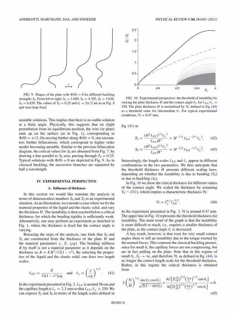
FIG. 10. Experimental perspective: the threshold of instability byvarying the plate thickness H and the contact angle θe, for �EG/�γ =250. The plate thickness H is normalized by H, defined in Eq. (44)as a threshold value for intermediate θe. For typical experimentalconditions, H = 0.47 mm.
Eq. (41) as
T0 = (H 2�EG)1/3�γ3
�EGH 3= H−7/3 �EG
−2/3 �γ3, (42)
S0 = (H 2�EG)2/3�γ2
�EGH 3= H−5/3 �EG
−1/3 �γ2. (43)
Interestingly, the length scales �EG and �γ appear in differentcombinations in the two parameters. We thus anticipate thatthe threshold thickness H presents different scaling laws,depending on whether the instability is due to bending (T0)or due to buckling (S0).
In Fig. 10 we show the critical thickness for different valuesof the contact angle. We scaled the thickness by assumingT0 ∼ O(1), which implies a characteristic thickness H:
H = �9/7γ �
−2/7EG . (44)
In the experiment presented in Fig. 3, H is around 0.47 mm.The upper line in Fig. 10 represents the threshold thickness forinstability. The main trend of the graph is that the instabilityis more difficult to reach, i.e., requires a smaller thickness ofthe plate, as the contact angle θe is decreased.
A key result, however, is that even for very small contactangles there is still an instability due to the torque exerted bythe normal forces. This contrasts the classical buckling picture,since for small θe the capillary forces are not compressing, butare in fact pulling on the plate. Note that in this regime ofsmall θe, T0 → ∞, and therefore H, as defined in Eq. (44), isno longer the correct length scale for the threshold thickness.Rather, in this regime the critical thickness is obtainedfrom
2
(HH
)7/3 sin θe| cos θe|√2(1 − sin θe)
+Ai′
[2(H
H
)5/3( �EG
�γ
)1/7cos θe
]Ai
[2(H
H
)5/3( �EG�γ
)1/7cos θe
] = 0.
(45)
061601-8

ELASTOCAPILLARY INSTABILITY UNDER PARTIAL . . . PHYSICAL REVIEW E 84, 061601 (2011)
For θe → 0 and H/H → 0:
√2
(HH
)7/3
θe −[
2
(HH
)5/3 (�EG
�γ
)1/7 ]1/2
= 0, (46)
which yields
H
H =(
�γ
�EG
)1/21
θe2/3 . (47)
This asymptotic form is shown as the dashed line in Fig. 10.Indeed, this regime involves a different combination of �EG
and �γ than H.Above π/2, one enters the usual buckling regime. The
graph also reveals the higher order buckling modes. From theprevious paragraphs, a good approximation can be obtained as
H
H =(
�EG
�γ
)1/21 [3π
8(4n + 1)
]−2/5
(−2 cos θe)3/35 . (48)
The onset is generated by the highest of the lines. Finally,note that there is an optimal contact angle, slightly beforeθe = π , for which the instability is most easily reached. Thescaling near θe = π turns out to be
H
H =(
2
|c0|)3/5 (
�EG
�γ
)3/35
≈ 1.4988
(�EG
�γ
)3/35
. (49)
To summarize, the critical thickness below which the platebecomes unstable increases with the contact angle θe, exceptvery close to θe = π , where the thickness displays a maximum.Intriguingly, the dependence of the characteristic thicknesson the material parameters is not universal, but depends onthe contact angle. Three regimes can be identified, involvingdifferent combinations of ρg, γ , and E. At very small contactangles, one finds from Eq. (47)
H ∝ (ρg)−1/3γ 2/3E−1/3θe2/3. (50)
Close to θe = π one has [Eq. (49)]
H ∝ (ρg)−2/5γ 3/5E−1/5, (51)
while at intermediate contact angles one has [Eq. (44)]
H ∝ (ρg)−5/14γ 9/14E−2/7. (52)
B. Influence of contact angle hysteresis
Another important experimental feature is that one can-not eliminate a substantial hysteresis of the contact angle.This means that θL = θR , with typical experimental values�θ ≈ 0.1 (in radians). Taking this hysteresis into account inthe model, we find a small shift in the threshold of instability.However, the fact that hysteresis breaks the left-right symmetryof the problem has a much more pronounced effect onthe general structure of the solutions and their bifurcationdiagrams.
To illustrate this, we first show two bifurcation diagramscorresponding to Fig. 10 in the case without hysteresis(�θ = 0). Figures 11(a) and 11(b) are both obtained byvarying θe, for two different values of the plate thickness.The upper plot corresponds to H/H = 1.54, for which asingle bifurcation is observed. The lower plot corresponds to
0
0
π/4
π/4
−π/4
3π/4π/2−π/2
π/2
π
0
0
π/4
π/4
−π/4
3π/4π/2−π/2
π/2
π
(a)
(b)
FIG. 11. Bifurcation diagram, �(0) versus θe for �EG/�γ = 250.The two panels correspond to different cross sections of Fig. 10,namely (a) H/H = 1.54, and (b) H/H = 0.77.
H/H = 0.77, for which the higher order buckling modes arecrossed.
The effect of contact angle hysteresis is revealed in Fig. 12,comparing the bifurcation diagrams for �θ = 0 and �θ = 0.1.Clearly, the left-right symmetry of the problem is broken bythe hysteresis, as reflected by the splitting of the branches
0
0
π/4
π/4
−π/4
3π/4π/2−π/2
π/2
π
FIG. 12. Effect on hysteresis on the bifurcation diagram, �(0)versus θe, in the case H/H = 1.71 and �EG/�γ = 250. �θ = 0.1(thick lines) is compared to the case without hysteresis (thin line).The hysteresis allows for stable solutions of nonzero amplitude �(0).
061601-9

ANDREOTTI, MARCHAND, DAS, AND SNOEIJER PHYSICAL REVIEW E 84, 061601 (2011)
for �(0) > 0 and for �(0) < 0. A practical consequence isthat, below threshold, the stable solutions actually correspondto a nonzero �(0). This means that the stable states do notcorrespond to a straight plate: the plate is always slightly bent,even before the instability occurs. This effect is clearly visiblein Fig. 3, which corresponds to a photograph of a stable platethat is indeed deformed toward a small angle.
V. DISCUSSION
A. Spatial distribution of capillary forces
The total force exerted by the liquid on the solid isγ cos θe per unit contact line, as follows from a thermodynamicargument based on virtual work (Sec. II). In this paper, we havetreated these capillary forces as if they were perfectly localizedat the contact line—see the inset of Fig. 3. However, this is notnecessarily a representation of the real distribution of capillaryforces, since the solid can be submitted to a Laplace pressurewherever the solid surface is curved [18,20,21]. In the case ofthe plate, for example, this curvature is localized at the bottomedges and could induce an upward force due to a Laplacepressure on the solid. To restore the thermodynamic resultantforce, this necessarily means that additional downward forcesmust be present at the contact line to counteract this effect.Here we will not discuss the origin and nature of this Laplacepressure and we refer the interested reader to Refs. [18,21];assuming that it exists, how are the results derived in this paperaffected?
We consider the two-dimensional situation depicted inFig. 13, where the bottom of the solid can take an arbitraryshape. The immersed part of the solid is submitted to adistribution of pressure γsκ proportional to the curvature κ
and to the relevant surface tension coefficient γs . The totalforce exerted on the solid due to this curvature effect is writtenas a contour integral:
Fκ =∫ R
L
γsκ n dl =∫ R
L
γs
d tdl
dl = [γs t]RL, (53)
where l is the curvilinear coordinate, t is the local tangentvector, and n is the local normal vector. Elementary geometrygives d t/dl = κ n, where κ is the local curvature of the surface.Hence Eq. (53) shows that the Laplace contribution to the
FIG. 13. Sketch of the quantities required to compute the Laplacepressure exerted on a solid of arbitrary shape. See text for details.
total capillary force depends only on the tangent vectorsat the contact line and is independent of the shape of theimmersed solid. As mentioned above, this must be com-pensated by an additional force at the contact line to restorethe thermodynamic result. Similarly, the total moment of theLaplace force can be written as a contour integral:
τκ =∫ R
L
γs r ∧ κ n dl =∫ R
L
γs
d r ∧ tdl
dl = [γs r ∧ t]RL, (54)
where we have used the property d r/dl = t . As for theresulting force, the moment also does not depend on the shapeof the object and is equal to the moment of a force γs t thatwould be localized at the contact line. In other words, neitherthe total force nor the total moment exerted on the upper partof the plate depend on the distribution of capillary forces belowthe surface.
We thus conclude that all results presented in this paperare perfectly insensitive to the true spatial distribution ofthe capillary forces. Reciprocally, it also implies that theLaplace pressure on a solid cannot be characterized usingbending or buckling experiments. Instead, one must measurethe deformations of the solid surface [20].
An important question in the present context is to whatextent the analysis would be modified in case we considereda thin wire instead of a thin plate. Although, we would expecta similar phenomenology for a cylindrical rod, a quantitativedifference exists. The capillary length appears as it sets thetypical moment arm for the torque. Changing the solid from aplate to a thin wire of radius R � �γ , as in Fig. 1, the lengthscale for the meniscus is determined by the radius rather thanthe capillary length. The corresponding dimensionless bendingparameter for a thin rod would thus be �χR/�2
EC , but thequalitative features of the instability will be comparable to thetwo-dimensional plate.
B. Conclusion
In this paper we identified two separate mechanisms thatcan lead to elastocapillary instability of a flexible plate partiallyimmersed in a liquid. The tangential components of thecapillary forces can induce buckling whenever the contactangle θe > π/2. By contrast, the normal components of thecapillary forces, which are proportional to γ sin θe, havea destabilizing effect for arbitrary θe > 0. The underlyingphysical mechanism can be inferred from the inset of Fig. 3:a small perturbation of the plate inclination induces a longermoment arm one one side of the plate, such that the resultanttorque is destabilizing. Alternatively, one may consider a freeenergy argument, showing that the immersed state of the wireis energetically unfavorable whenever the liquid is partiallywetting (Fig. 2). We found that the dimensionless numberassociated to this bending mechanism not only involves theelastocapillary length �EC , but also the capillary length �γ .The capillary length appears as it sets the typical moment armfor the torque. Changing the solid from a plate to a thin wireof radius R � �γ , as in Fig. 1, the length scale for the momentarm becomes R. By estimating the physical parameters for thewire in Fig. 1, we conclude that in this particular example theinstability is not triggered by bending or buckling individually,but by a combination of the two mechanisms.
061601-10

ELASTOCAPILLARY INSTABILITY UNDER PARTIAL . . . PHYSICAL REVIEW E 84, 061601 (2011)
The analysis of the present paper focused on the transitionof an immersed plate, partially wetted on both sides, to astate where the plate is pushed to free surface. This can beconsidered as the inverse of the “piercing” problem that isrelevant, e.g., for water striders [2]. In the case of piercing,the contact line remains pinned on the edge of the solid beforeentering the liquid, such that one side of the solid remainscompletely dry. It would be interesting to see if the equivalent
of the stability threshold (36) could be derived for piercing aswell.
ACKNOWLEDGMENTS
We gratefully acknowledge J. Bico and B. Roman forenlightening discussions. J.H.S. acknowledges support fromParis-Diderot University.
[1] J. W. M. Bush and D. L. Hu, Annu. Rev. Fluid Mech. 38, 339(2006).
[2] K. J. Park and H.-Y. Kim, J. Fluid Mech. 610, 381 (2008).[3] N. Chakrapani, B. Wei, A. Carrillo, P. M. Ajayan, and R. S.
Kane, Proc. Natl. Acad. Sci. USA 101, 4009 (2004).[4] S. Neukirch, B. Roman, B. de Gaudemaris, and J. Bico, J. Mech.
Phys. Solids 55, 1212 (2007).[5] F. Chiodi, B. Roman, and J. Bico, Europhys. Lett. 90, 44006
(2010).[6] J. Bico, B. Roman, L. Moulin, and A. Boudaoud, Nature
(London) 432, 690 (2004).[7] C. Py, P. Reverdy, L. Doppler, J. Bico, B. Roman, and C. N.
Baroud, Phys. Rev. Lett. 98, 156103 (2007).[8] A. Boudaoud, J. Bico, and B. Roman, Phys. Rev. E 76, 060102
(2007).[9] C. Py, P. Reverdy, L. Doppler, J. Bico, B. Roman,
and C. N. Baroud, Eur. Phys. J. Spec. Top. 166, 67(2009).
[10] B. Roman and J. Bico, J. Phys.: Condens. Matter 22, 493101(2010).
[11] J. Hure, B. Roman, and J. Bico, Phys. Rev. Lett. 106, 174301(2011).
[12] J. W. van Honschoten, J. W. Berenschot, T. Ondarcuhu, R. G.P. Sanders, J. Sundaram, M. Elwenspoek, and N. R. Tas, Appl.Phys. Lett. 97, 014103 (2010).
[13] S. P. Timoshenko and S. Woinowsky-Krieger, Theory of Platesand Shells, 2nd ed. (McGraw-Hill, Singapore, 1959).
[14] L. D. Landau and E. M. Lifshitz, Theory of Elasticity, 3rd ed.(Butterworth-Heinemann, Oxford, 1986).
[15] S. Tawfick, M. De Volder, and A. J. Hart, Langmuir 27, 6389(2011).
[16] A. L. Hazel and M. Heil, Proc. R. Soc. London, Ser. A 461, 1847(2005).
[17] P. G. de Gennes, F. Brochard-Wyart, and D. Qur, Capillarity andWetting Phenomena: Drops, Bubbles, Pearls, Waves (Springer,New York, 2003).
[18] S. Das, A. Marchand, B. Andreotti, and J. H. Snoeijer, Phys.Fluids 23, 072006 (2011).
[19] A. Marchand, J. Weijs, B. Andreotti, and J. H. Snoeijer, Am. J.Phys. 79, 999 (2011).
[20] E. R. Jerison, Y. Xu, L. A. Wilen, and E. R. Dufresne, Phys. Rev.Lett. 106, 186103 (2011).
[21] S. Mora, T. Phou, J.-M. Fromental, L. M. Pismen, andY. Pomeau, Phys. Rev. Lett. 105, 214301 (2011).
061601-11