Embed Size (px)
Citation preview
Wetting and spreading
Daniel Bonn
Laboratoire de Physique Statistique, Ecole Normale Supérieure, 24 rue Lhomond, 75005Paris, France and van der Waals-Zeeman Institute, University of Amsterdam,Valckenierstraat 65, 1018 XE, Amsterdam, The Netherlands
Jens Eggers
School of Mathematics, University of Bristol, University Walk, Bristol BS8 1TW, UnitedKingdom
Joseph Indekeu
Instituut voor Theoretische Fysica, Katholieke Universiteit Leuven, 3001 Leuven, Belgium
Jacques Meunier and Etienne Rolley
Laboratoire de Physique Statistique, Ecole Normale Supérieure, 24 rue Lhomond, 75005Paris, France
�Published 27 May 2009�
Wetting phenomena are ubiquitous in nature and technology. A solid substrate exposed to theenvironment is almost invariably covered by a layer of fluid material. In this review, the surface forcesthat lead to wetting are considered, and the equilibrium surface coverage of a substrate in contact witha drop of liquid. Depending on the nature of the surface forces involved, different scenarios forwetting phase transitions are possible; recent progress allows us to relate the critical exponents directlyto the nature of the surface forces which lead to the different wetting scenarios. Thermal fluctuationeffects, which can be greatly enhanced for wetting of geometrically or chemically structuredsubstrates, and are much stronger in colloidal suspensions, modify the adsorption singularities.Macroscopic descriptions and microscopic theories have been developed to understand and predictwetting behavior relevant to microfluidics and nanofluidics applications. Then the dynamics of wettingis examined. A drop, placed on a substrate which it wets, spreads out to form a film. Conversely, anonwetted substrate previously covered by a film dewets upon an appropriate change of systemparameters. The hydrodynamics of both wetting and dewetting is influenced by the presence of thethree-phase contact line separating “wet” regions from those that are either dry or covered by amicroscopic film only. Recent theoretical, experimental, and numerical progress in the description ofmoving contact line dynamics are reviewed, and its relation to the thermodynamics of wetting isexplored. In addition, recent progress on rough surfaces is surveyed. The anchoring of contact linesand contact angle hysteresis are explored resulting from surface inhomogeneities. Further, new waysto mold wetting characteristics according to technological constraints are discussed, for example, theuse of patterned surfaces, surfactants, or complex fluids.
DOI: 10.1103/RevModPhys.81.739 PACS number�s�: 68.08.Bc, 47.55.np, 47.15.gm, 68.35.Dv
CONTENTS
I. Introduction 740
A. How, what, and why? 740
B. Statics 741
1. Basic surface thermodynamics 741C. Drop spreading: Basic concepts 743
1. Huh and Scriven’s paradox 7442. Apparent and microscopic contact angles 7453. Spreading laws 746
D. Real solid surfaces: Contact line hysteresis 746II. Equilibrium Wetting Phenomena 748
A. Equilibrium wetting behavior in relationto the intermolecular interactions 748
1. Long-range forces: The Hamaker constant 7492. Short-range forces: The phenomenological
Cahn-Landau theory of wetting 751B. Real systems: Three scenarios for wetting transitions 752
1. First-order and critical wetting 753
2. Long-range critical wetting 754
C. Fluctuation effects and short-range critical wetting 756
D. Hot topics 757
1. Wetting in colloid-polymer mixtures 757
2. Wetting on structured surfaces 759
3. Wedge filling transitions 761
4. Incomplete wetting by crystalline phases 763
5. Electrowetting 763
III. Dynamics 764
A. Contact line region 765
B. Matching to a macroscopic flow 766
1. Numerical simulations 767
C. Experiment 768
1. Zero equilibrium contact angle 769
2. Finite equilibrium contact angle 770
D. Contact line dissipation and microscopic contact
angles 771
REVIEWS OF MODERN PHYSICS, VOLUME 81, APRIL–JUNE 2009
0034-6861/2009/81�2�/739�67� ©2009 The American Physical Society739
1. Free energy balance 7712. Sources of dissipation 7723. Precursor films 773
E. Matching to the contact line 7731. Sharp interface 7732. Diffuse interface 774
F. Molecular dynamics 775G. Receding contact line 776H. Dewetting 777I. Linear instabilities of driven contact lines 779J. Hot topics 780
1. Corners and air pockets 7802. Spreading of complex fluids: Polymers and
surfactants 7823. Evaporating drops 783
IV. Disordered Solid Surfaces 784A. How to model a real solid surface? 784B. The single defect case 785
1. Pinning on a single defect 7852. Dilute defects 7863. Dynamics 787
C. Substrates with interacting defects 7881. The shape of the contact line at equilibrium 7882. Hysteresis 7893. Predictions and measurement of the critical
behavior 789a. Equation of motion 789b. Critical behavior 790c. Beyond the harmonic approximation 791
D. Thermal noise 791E. Hot topics 792
1. Hysteresis again 7922. Prewetting transition on disordered
substrates 792Acknowledgments 793References 793
I. INTRODUCTION
A. How, what, and why?
Wetting phenomena are an area where chemistry,physics, and engineering intersect. Surface chemistry isof key importance in determining wetting behavior, andmuch research has been devoted to modifying the sur-face chemistry of various solids in order to obtain spe-cific wetting properties �Durian and Franck, 1987�. Moreor less standard chemical means to do this is, for in-stance, plasma treatment �Wu, 1982� or silanization�Brzoska et al., 1992�. By such treatments, one modifiesthe chemical properties of the surface of the material,and hence the contact energy of the surface with liquids,vapors, or other solids.
As these “chemical’’ interactions act over the scale ofmolecules, one often refers to them as short-ranged in-teractions. In addition to the surface chemistry, surfaceforces such as van der Waals or electrostatic forces areparamount for determining whether or not a fluid willwet a given surface. These forces have been studied indetail by physicists and physical chemists. van der Waals
surface forces can still be important over distances cor-responding to a few tens of molecules, because their al-gebraic decay is rather slow; we hence call them “longranged.” The van der Waals forces are responsible forthe equilibrium thickness of wetting films, and are be-lieved to be important for the way fluids spread over asolid surface. Both van der Waals and electrostaticforces determine the stability of soap films �Vrij, 1966�.
Indeed, wetting and spreading are of key importancefor many applications. At large scales, wetting or non-wetting plays an important role in oil recovery �Ber-trand, Bonn, Broseta, Shahidzadeh, et al., 2002� and theefficient deposition of pesticides on plant leaves �Berg-eron et al., 2000�, and also in the drainage of water fromhighways �Shahidzadeh et al., 2003� and the cooling ofindustrial reactors. On a smaller scale, wetting solutionshave been proposed to solve technological problems inmicrofluidics and nanoprinting, inkjet printing, etc.�Tabeling, 2004�. All these phenomena are governed bythe surface and interfacial interactions, acting usually atsmall �a few nanometers for van der Waals or electro-static interactions� or very small �molecular� distances.These length scales are now being probed with relativelynew experimental techniques, such as atomic force mi-croscopy and surface force apparatus, or theoreticaltools, such as molecular dynamics, etc., allowing new in-sights into the old problems of surface forces. In addi-tion, new concepts are being introduced to influenceboth the statics and dynamics of wetting, such as pat-terned surfaces, surfactants, and non-Newtonian flow, inorder to solve some of the technological problems men-tioned above.
In this review, we first study the equilibrium state ofliquids deposited on a solid or another liquid, and howthis state is determined by both short-range and long-range molecular interactions. As a thermodynamic pa-rameter, such as the temperature, is varied, the systemmay pass from one wetting state to another. These so-called wetting transitions have perhaps been the mostactive subdiscipline in the field of phase transitions overthe past two decades. In particular, a number of recentexperiments have reinvigorated interest and challengedsome long-held theoretical views.
Next we describe the dynamic problems involved inreaching an equilibrium state, and their relation to thesurface chemistry. This is a subtle problem, as a classicalhydrodynamic description breaks down at the movingcontact line at the edge of a spreading droplet, and mi-croscopic features have to be invoked. As a result, bothlarge-scale �hydrodynamic� features and short-scale �mo-lecular� dynamics are inextricably linked into a trulymultiscale problem.
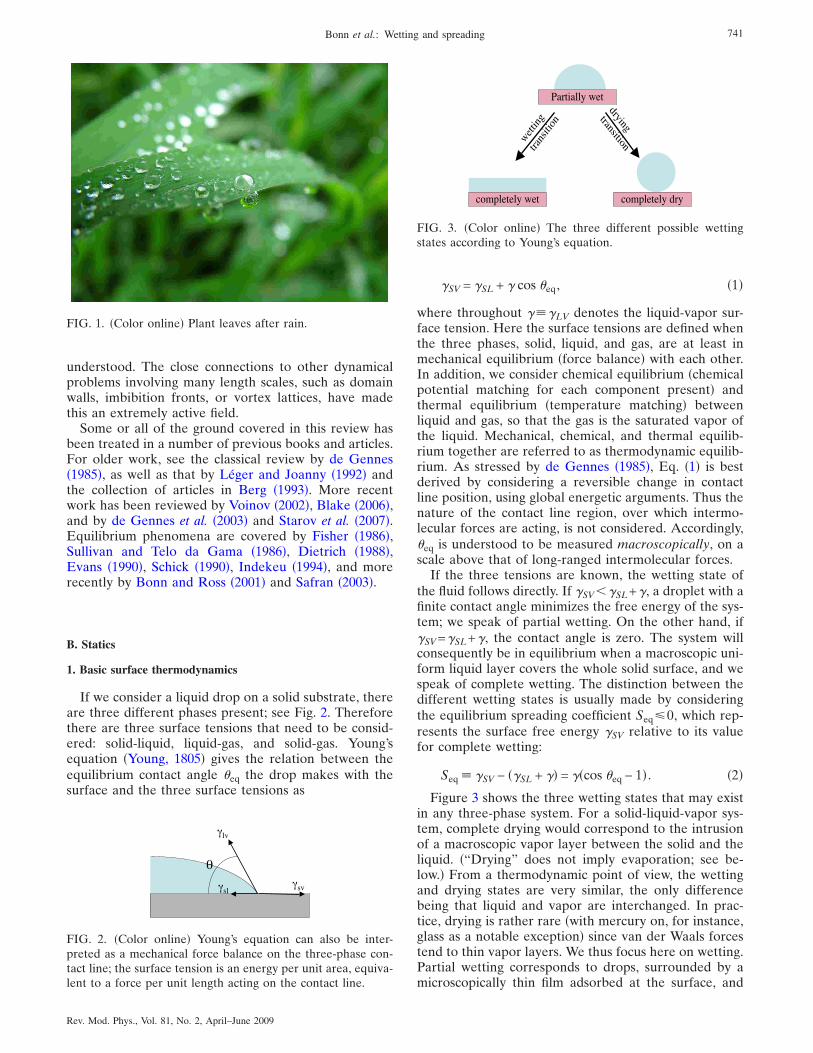
Finally, wetting is a subject in which disorder plays animportant role in practice, and even under idealizedlaboratory conditions, for both statics and dynamics. Onthe one hand, impurities may lead to frustration, so thatthe true equilibrium state is never reached: a small drop-let is often observed to rest on an inclined surface; seeFig. 1. On the other hand, the resulting roughness of thecontact line leads to complicated dynamics, still poorly
740 Bonn et al.: Wetting and spreading
Rev. Mod. Phys., Vol. 81, No. 2, April–June 2009
understood. The close connections to other dynamicalproblems involving many length scales, such as domainwalls, imbibition fronts, or vortex lattices, have madethis an extremely active field.
Some or all of the ground covered in this review hasbeen treated in a number of previous books and articles.For older work, see the classical review by de Gennes�1985�, as well as that by Léger and Joanny �1992� andthe collection of articles in Berg �1993�. More recentwork has been reviewed by Voinov �2002�, Blake �2006�,and by de Gennes et al. �2003� and Starov et al. �2007�.Equilibrium phenomena are covered by Fisher �1986�,Sullivan and Telo da Gama �1986�, Dietrich �1988�,Evans �1990�, Schick �1990�, Indekeu �1994�, and morerecently by Bonn and Ross �2001� and Safran �2003�.
B. Statics
1. Basic surface thermodynamics
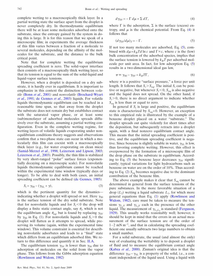
If we consider a liquid drop on a solid substrate, thereare three different phases present; see Fig. 2. Thereforethere are three surface tensions that need to be consid-ered: solid-liquid, liquid-gas, and solid-gas. Young’sequation �Young, 1805� gives the relation between theequilibrium contact angle �eq the drop makes with thesurface and the three surface tensions as
�SV = �SL + � cos �eq, �1�
where throughout ���LV denotes the liquid-vapor sur-face tension. Here the surface tensions are defined whenthe three phases, solid, liquid, and gas, are at least inmechanical equilibrium �force balance� with each other.In addition, we consider chemical equilibrium �chemicalpotential matching for each component present� andthermal equilibrium �temperature matching� betweenliquid and gas, so that the gas is the saturated vapor ofthe liquid. Mechanical, chemical, and thermal equilib-rium together are referred to as thermodynamic equilib-rium. As stressed by de Gennes �1985�, Eq. �1� is bestderived by considering a reversible change in contactline position, using global energetic arguments. Thus thenature of the contact line region, over which intermo-lecular forces are acting, is not considered. Accordingly,�eq is understood to be measured macroscopically, on ascale above that of long-ranged intermolecular forces.
If the three tensions are known, the wetting state ofthe fluid follows directly. If �SV��SL+�, a droplet with afinite contact angle minimizes the free energy of the sys-tem; we speak of partial wetting. On the other hand, if�SV=�SL+�, the contact angle is zero. The system willconsequently be in equilibrium when a macroscopic uni-form liquid layer covers the whole solid surface, and wespeak of complete wetting. The distinction between thedifferent wetting states is usually made by consideringthe equilibrium spreading coefficient Seq�0, which rep-resents the surface free energy �SV relative to its valuefor complete wetting:
Seq � �SV − ��SL + �� = ��cos �eq − 1� . �2�
Figure 3 shows the three wetting states that may existin any three-phase system. For a solid-liquid-vapor sys-tem, complete drying would correspond to the intrusionof a macroscopic vapor layer between the solid and theliquid. �“Drying” does not imply evaporation; see be-low.� From a thermodynamic point of view, the wettingand drying states are very similar, the only differencebeing that liquid and vapor are interchanged. In prac-tice, drying is rather rare �with mercury on, for instance,glass as a notable exception� since van der Waals forcestend to thin vapor layers. We thus focus here on wetting.Partial wetting corresponds to drops, surrounded by amicroscopically thin film adsorbed at the surface, and
FIG. 1. �Color online� Plant leaves after rain.
FIG. 2. �Color online� Young’s equation can also be inter-preted as a mechanical force balance on the three-phase con-tact line; the surface tension is an energy per unit area, equiva-lent to a force per unit length acting on the contact line.
FIG. 3. �Color online� The three different possible wettingstates according to Young’s equation.
741Bonn et al.: Wetting and spreading
Rev. Mod. Phys., Vol. 81, No. 2, April–June 2009
complete wetting to a macroscopically thick layer. In apartial wetting state the surface apart from the droplet isnever completely dry. In thermodynamic equilibriumthere will be at least some molecules adsorbed onto thesubstrate, since the entropy gained by the system in do-ing this is large. It is for this reason that we speak of amicroscopic film; in experiments the average thicknessof this film varies between a fraction of a molecule toseveral molecules, depending on the affinity of the mol-ecules for the substrate, and the distance to the bulkcritical point.
Note that for complete wetting the equilibriumspreading coefficient is zero. The solid-vapor interfacethen consists of a macroscopically thick wetting layer, sothat its tension is equal to the sum of the solid-liquid andliquid-vapor surface tensions.
However, when a droplet is deposited on a dry sub-strate, it is hardly ever in equilibrium. It is important toemphasize in this context the distinction between vola-tile �Bonn et al., 2001� and nonvolatile �Brochard-Wyartet al., 1991; de Gennes et al., 2003� liquids. For volatileliquids thermodynamic equilibrium can be reached in areasonable time span, so that away from the dropletthe substrate does not remain dry but establishes contactwith the saturated vapor phase, or at least some�sub�monolayer of adsorbed molecules spreads diffu-sively over the substrate, assuming a partial wetting con-figuration. Even in the complete wetting regime, forwetting layers of volatile liquids evaporating under non-equilibrium conditions theory suggests and observationsconfirm that a two-phase state can occur in which a mo-lecularly thin film can coexist with a macroscopicallythick layer �e.g., for water evaporating on clean mica��Samid-Merzel et al., 1998; Leizerson and Lipson, 2003;Leizerson et al., 2003�. Possibly, the thin film is stabilizedby very short-ranged “polar” surface forces �exponen-tially decaying on a microscopic scale�. For nonvolatileliquids thermodynamic equilibrium cannot be reachedwithin the experimental time window �typically days orlonger�. To be able to deal with both cases, an initialspreading coefficient can be defined �de Gennes, 1985�:
Si = �S0 − ��SL + �� , �3�
which is the pertinent quantity for the dynamics—indicating whether a droplet will spread or not. Here �S0is the surface tension of the dry solid substrate. Notethat for nonvolatile liquids and for Si�0 the drop willdisplay a finite static contact angle, say �i, which is notthe equilibrium angle �eq, but is found by replacing �SVby �S0 in Eq. �1�. For nonvolatile liquids and Si�0 thedroplet will flatten as it attempts to spread, while pre-serving its volume �again, within the experimental timewindow�. This volume constraint is essential for describ-ing nonvolatile adsorbates and leads to a “final” statewhich differs from an equilibrium adsorbed film. We re-turn to this difference and quantify it in Sec. II.A.
The equilibrium tension �SV is lower than �S0 due toadsorption of molecules on the solid from the vaporphase. This follows from the Gibbs adsorption equation�Rowlinson and Widom, 1982�
d�SV = − � d� + � dT , �4�
where � is the adsorption, � is the surface �excess� en-tropy, and � is the chemical potential. From Eq. �4� itfollows that
�d�SV/d��T = − � . �5�
If not too many molecules are adsorbed, Eq. �5�, com-bined with d�=kBTd ln c and �c, where c is the �low�bulk concentration of the adsorbed species, implies thatthe surface tension is lowered by kBT per adsorbed mol-ecule per unit area. In fact, for low adsorption Eq. �5�results in a two-dimensional ideal gas law,
� �S0 − �SV = kBT� , �6�
where is a positive “surface pressure,” a force per unitlength. It follows that Si�Seq. The initial Si can be posi-tive or negative, but whenever Si�0, Seq is also negativeand the liquid does not spread. On the other hand, ifSi�0, there is no direct argument to indicate whetherSeq is less than or equal to zero.
In general if Si is large and positive, the equilibriumstate is characterized by Seq=0. However, an exceptionto this empirical rule is illustrated by the example of abenzene droplet placed on a water “substrate.” Thedroplet spreads out quite violently for short times afterthe deposition, but subsequently retracts into a dropletagain, with a final nonzero equilibrium contact angle.This means that the initial spreading coefficient is posi-tive, and the equilibrium spreading coefficient is nega-tive. Since benzene is slightly soluble in water, �SL is low,thus favoring complete wetting. However, this effect isoverpowered by the formation of a microscopic film ofthe drop phase on the substrate in equilibrium. Accord-ing to Eq. �5� the benzene layer decreases �SV signifi-cantly; typical variations for light hydrocarbons such asbenzene on water are on the order of 10%. Thus accord-ing to Eq. �2� Seq becomes negative due to the dominantcontribution of the benzene film.
The above example makes it clear that Seq cannot bedetermined in general from the surface tensions of thepure substances. In the more favorable situation of adrop �L2� wetting a liquid substrate L1, for which moregeneral equations than Eq. �1� apply �Rowlinson andWidom, 1982�, care must be taken to measure the ten-sions �L1V and �L2V each in the presence of the otherliquid. The measurement of �L1L2
is standard �Ferguson,1929�. This usually works reasonably well; however, itshould be kept in mind that the errors in an actual mea-surement of the surface tension are of the order of1–2 mN m−1, and that in calculating the spreading coef-ficient one usually subtracts two large numbers to obtaina small number.
For a solid substrate, the usual �and almost the only�way of evaluating the wettability is to deposit a dropletof fluid and to measure the equilibrium contact angle�Kabza et al., 2000�. Zisman’s original idea is that thedifference �SV−�SL is a property of the solid, i.e., a con-stant independent of the liquid used. Using a liquid with
742 Bonn et al.: Wetting and spreading
Rev. Mod. Phys., Vol. 81, No. 2, April–June 2009
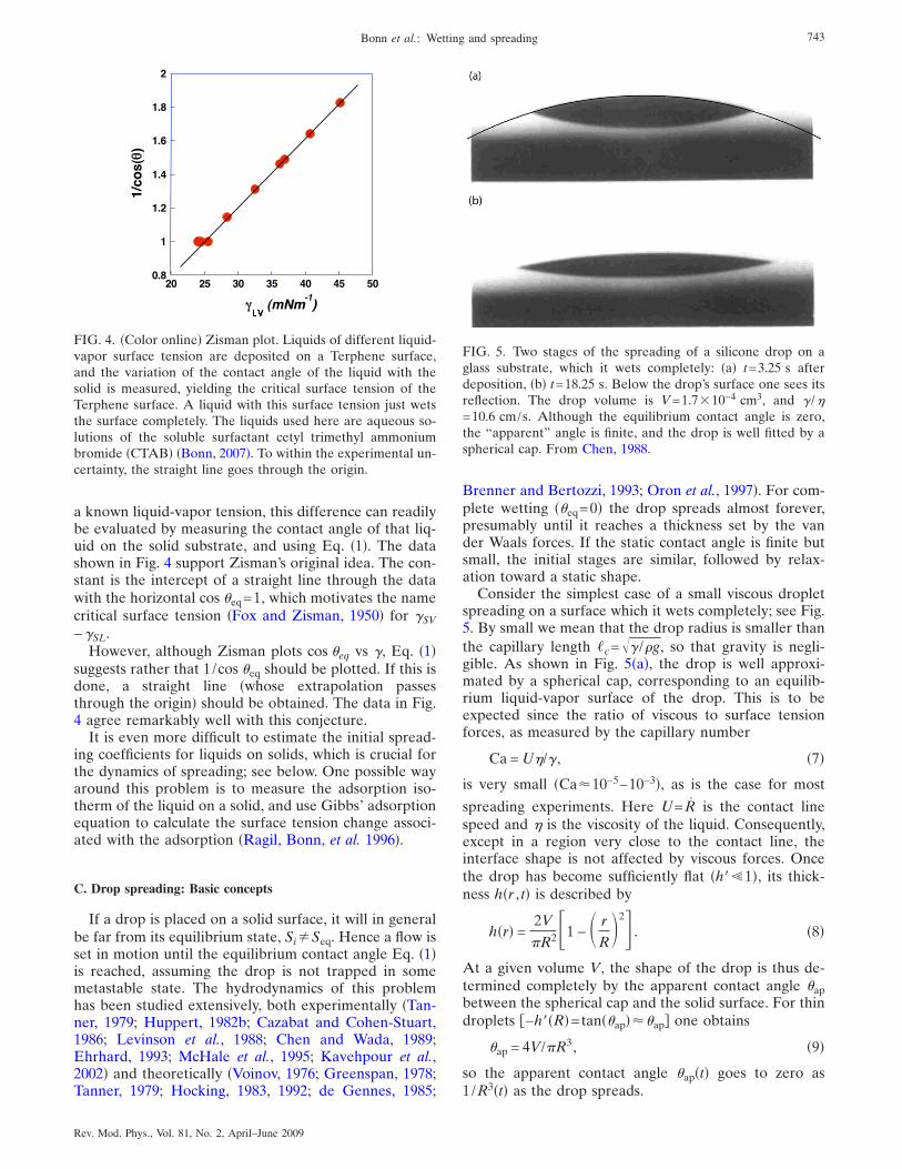
a known liquid-vapor tension, this difference can readilybe evaluated by measuring the contact angle of that liq-uid on the solid substrate, and using Eq. �1�. The datashown in Fig. 4 support Zisman’s original idea. The con-stant is the intercept of a straight line through the datawith the horizontal cos �eq=1, which motivates the namecritical surface tension �Fox and Zisman, 1950� for �SV−�SL.
However, although Zisman plots cos �eq vs �, Eq. �1�suggests rather that 1/cos �eq should be plotted. If this isdone, a straight line �whose extrapolation passesthrough the origin� should be obtained. The data in Fig.4 agree remarkably well with this conjecture.
It is even more difficult to estimate the initial spread-ing coefficients for liquids on solids, which is crucial forthe dynamics of spreading; see below. One possible wayaround this problem is to measure the adsorption iso-therm of the liquid on a solid, and use Gibbs’ adsorptionequation to calculate the surface tension change associ-ated with the adsorption �Ragil, Bonn, et al. 1996�.
C. Drop spreading: Basic concepts
If a drop is placed on a solid surface, it will in generalbe far from its equilibrium state, Si�Seq. Hence a flow isset in motion until the equilibrium contact angle Eq. �1�is reached, assuming the drop is not trapped in somemetastable state. The hydrodynamics of this problemhas been studied extensively, both experimentally �Tan-ner, 1979; Huppert, 1982b; Cazabat and Cohen-Stuart,1986; Levinson et al., 1988; Chen and Wada, 1989;Ehrhard, 1993; McHale et al., 1995; Kavehpour et al.,2002� and theoretically �Voinov, 1976; Greenspan, 1978;Tanner, 1979; Hocking, 1983, 1992; de Gennes, 1985;
Brenner and Bertozzi, 1993; Oron et al., 1997�. For com-plete wetting ��eq=0� the drop spreads almost forever,presumably until it reaches a thickness set by the vander Waals forces. If the static contact angle is finite butsmall, the initial stages are similar, followed by relax-ation toward a static shape.
Consider the simplest case of a small viscous dropletspreading on a surface which it wets completely; see Fig.5. By small we mean that the drop radius is smaller thanthe capillary length �c=�� /�g, so that gravity is negli-gible. As shown in Fig. 5�a�, the drop is well approxi-mated by a spherical cap, corresponding to an equilib-rium liquid-vapor surface of the drop. This is to beexpected since the ratio of viscous to surface tensionforces, as measured by the capillary number
Ca = U�/� , �7�
is very small �Ca�10−5–10−3�, as is the case for most
spreading experiments. Here U= R is the contact linespeed and � is the viscosity of the liquid. Consequently,except in a region very close to the contact line, theinterface shape is not affected by viscous forces. Oncethe drop has become sufficiently flat �h� 1�, its thick-ness h�r , t� is described by
h�r� =2V
R2�1 − � r
R�2 . �8�
At a given volume V, the shape of the drop is thus de-termined completely by the apparent contact angle �apbetween the spherical cap and the solid surface. For thindroplets −h��R�=tan��ap���ap� one obtains
�ap = 4V/R3, �9�
so the apparent contact angle �ap�t� goes to zero as1/R3�t� as the drop spreads.
FIG. 4. �Color online� Zisman plot. Liquids of different liquid-vapor surface tension are deposited on a Terphene surface,and the variation of the contact angle of the liquid with thesolid is measured, yielding the critical surface tension of theTerphene surface. A liquid with this surface tension just wetsthe surface completely. The liquids used here are aqueous so-lutions of the soluble surfactant cetyl trimethyl ammoniumbromide �CTAB� �Bonn, 2007�. To within the experimental un-certainty, the straight line goes through the origin.
FIG. 5. Two stages of the spreading of a silicone drop on aglass substrate, which it wets completely: �a� t=3.25 s afterdeposition, �b� t=18.25 s. Below the drop’s surface one sees itsreflection. The drop volume is V=1.7�10−4 cm3, and � /�=10.6 cm/s. Although the equilibrium contact angle is zero,the “apparent” angle is finite, and the drop is well fitted by aspherical cap. From Chen, 1988.
743Bonn et al.: Wetting and spreading
Rev. Mod. Phys., Vol. 81, No. 2, April–June 2009
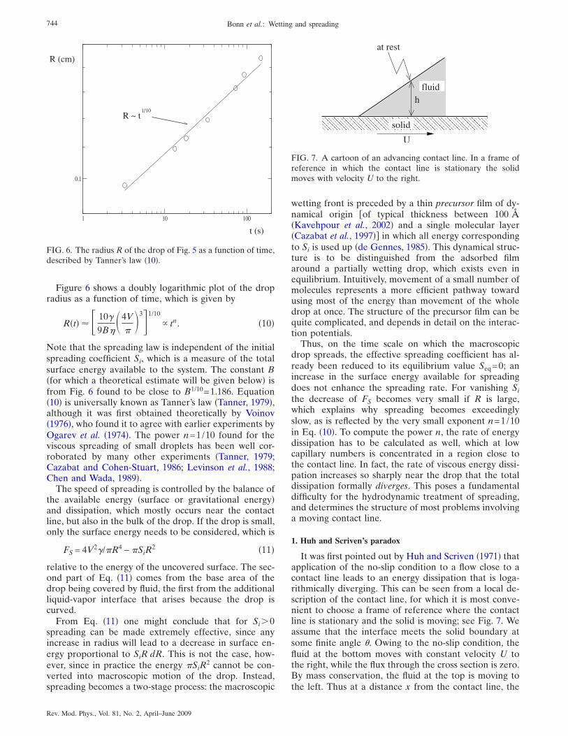
Figure 6 shows a doubly logarithmic plot of the dropradius as a function of time, which is given by
R�t� � � 10�
9B��4V
�31/10
tn. �10�
Note that the spreading law is independent of the initialspreading coefficient Si, which is a measure of the totalsurface energy available to the system. The constant B�for which a theoretical estimate will be given below� isfrom Fig. 6 found to be close to B1/10=1.186. Equation�10� is universally known as Tanner’s law �Tanner, 1979�,although it was first obtained theoretically by Voinov�1976�, who found it to agree with earlier experiments byOgarev et al. �1974�. The power n=1/10 found for theviscous spreading of small droplets has been well cor-roborated by many other experiments �Tanner, 1979;Cazabat and Cohen-Stuart, 1986; Levinson et al., 1988;Chen and Wada, 1989�.
The speed of spreading is controlled by the balance ofthe available energy �surface or gravitational energy�and dissipation, which mostly occurs near the contactline, but also in the bulk of the drop. If the drop is small,only the surface energy needs to be considered, which is
FS = 4V2�/R4 − SiR2 �11�
relative to the energy of the uncovered surface. The sec-ond part of Eq. �11� comes from the base area of thedrop being covered by fluid, the first from the additionalliquid-vapor interface that arises because the drop iscurved.
From Eq. �11� one might conclude that for Si�0spreading can be made extremely effective, since anyincrease in radius will lead to a decrease in surface en-ergy proportional to SiR dR. This is not the case, how-ever, since in practice the energy SiR
2 cannot be con-verted into macroscopic motion of the drop. Instead,spreading becomes a two-stage process: the macroscopic
wetting front is preceded by a thin precursor film of dy-namical origin of typical thickness between 100 �Kavehpour et al., 2002� and a single molecular layer�Cazabat et al., 1997�� in which all energy correspondingto Si is used up �de Gennes, 1985�. This dynamical struc-ture is to be distinguished from the adsorbed filmaround a partially wetting drop, which exists even inequilibrium. Intuitively, movement of a small number ofmolecules represents a more efficient pathway towardusing most of the energy than movement of the wholedrop at once. The structure of the precursor film can bequite complicated, and depends in detail on the interac-tion potentials.
Thus, on the time scale on which the macroscopicdrop spreads, the effective spreading coefficient has al-ready been reduced to its equilibrium value Seq=0; anincrease in the surface energy available for spreadingdoes not enhance the spreading rate. For vanishing Sithe decrease of FS becomes very small if R is large,which explains why spreading becomes exceedinglyslow, as is reflected by the very small exponent n=1/10in Eq. �10�. To compute the power n, the rate of energydissipation has to be calculated as well, which at lowcapillary numbers is concentrated in a region close tothe contact line. In fact, the rate of viscous energy dissi-pation increases so sharply near the drop that the totaldissipation formally diverges. This poses a fundamentaldifficulty for the hydrodynamic treatment of spreading,and determines the structure of most problems involvinga moving contact line.
1. Huh and Scriven’s paradox
It was first pointed out by Huh and Scriven �1971� thatapplication of the no-slip condition to a flow close to acontact line leads to an energy dissipation that is loga-rithmically diverging. This can be seen from a local de-scription of the contact line, for which it is most conve-nient to choose a frame of reference where the contactline is stationary and the solid is moving; see Fig. 7. Weassume that the interface meets the solid boundary atsome finite angle �. Owing to the no-slip condition, thefluid at the bottom moves with constant velocity U tothe right, while the flux through the cross section is zero.By mass conservation, the fluid at the top is moving tothe left. Thus at a distance x from the contact line, the
1 10 100
0.1
R ~ t
R (cm)
t (s)
1/10
FIG. 6. The radius R of the drop of Fig. 5 as a function of time,described by Tanner’s law �10�.
� � � � � � � � � � � � � � � � � � � � � � � � � � � �
� � � � � � � � � � � � � � � � � � � � � � � � � � � �
U
at rest
solid
fluidh
FIG. 7. A cartoon of an advancing contact line. In a frame ofreference in which the contact line is stationary the solidmoves with velocity U to the right.
744 Bonn et al.: Wetting and spreading
Rev. Mod. Phys., Vol. 81, No. 2, April–June 2009
typical vertical velocity gradient is dux /dz=U /h�x�,where h�x���x for small �. The rate of viscous dissi-pation per unit volume in a fluid of viscosity � is����dux /dz�2 �Landau and Lifshitz, 1984�. Integrating�U /h�2 over the wedge, one arrives at an estimate of thedissipation per unit time and unit length of the contactline,
Dvisc � � L
Lout �U
h�2
hdx =�U2
�ln�Lout/L� , �12�
where Lout is an appropriate outer length scale like theradius of the spreading droplet. In addition, we wereforced to introduce some small cutoff length L to makethe integral finite. Thus assuming standard continuumhydrodynamics with no slip, where L is set to zero, “noteven Herakles could sink a solid,” in Huh and Scriven’sapt phrase.
To account for the experimental observation that con-tact lines do in fact move, some microscopic featureshave to be built into the hydrodynamic description. As aresult, macroscopic flow features must depend to somedegree on those microscopic details, and the usual uni-versality of hydrodynamics is lost. In Table I we give alist of different mechanisms that have been proposed torelieve the contact line singularity. Unfortunately, onlyvery limited experimental information exists that wouldpinpoint one or the other mechanism. That is, as is to beexpected from Eq. �12�, the dependence on microscopicparameters is only logarithmic, so it is difficult to extractaccurate information on their values.
Based on the above estimates for the dissipation nearthe contact line, we are now in a position to derive thespreading law �10� by equating the rate of change of
the surface energy with the energy dissipation: FS=2RDvisc. To that end we take the angle � in Eq. �12�as an approximation for the apparent contact angle, and
find that DviscRR2 /�ap R2R4. Using FS R /R5, one ar-
rives at dR10/dt=10RR9const, and thus at Tanner’s law�10�. This estimate neglects the logarithmic factor ap-pearing in Eq. �12�, which may be a time-dependentquantity in itself. Only a more involved hydrodynamiccalculation, to which we return below, is able to predictthe exact form of the logarithmic corrections.
2. Apparent and microscopic contact angles
The concept of a contact angle becomes much moreproblematic in the out-of-equilibrium situation of amoving contact line, where the thermodynamic argu-ments leading to Eq. �1� no longer apply. Namely, thelocal angle the interface makes with the substrate de-pends strongly on scale, i.e., on the distance from thecontact line. On hydrodynamic scales, the strong diver-gence of viscous forces �Huh and Scriven, 1971� resultsin an interface slope that varies logarithmically with thedistance from the contact line, as confirmed experimen-tally �Chen and Wada, 1989; Marsh et al., 1993; Kaveh-pour et al., 2003�. We refer to this local angle, measuredmacroscopically at a specified distance from the contactline, as the dynamic contact angle �d.
As one approaches the contact line, the angle will alsobe affected by long-ranged forces. If finally the angle isdetermined on a molecular scale, the interface positionis no longer determined uniquely owing to thermal fluc-tuations and the diffusiveness of the interface itself. Theconcept of a microscopic or actual �Dussan, 1979� con-tact angle �m, determined directly at the contact line,thus has to be applied with care. It requires averagingover microscopic data e.g., from molecular simulations�Thompson and Robbins, 1989��, or the application ofwell-defined theoretical models, taking into account thediffusiveness of the interface �Qian et al., 2003�.
The only uniquely defined macroscopic angle is theapparent contact angle �9�, introduced in the context ofdrop spreading. Unfortunately, its definition is contin-gent on the fact that the interface shape sufficiently faraway from the contact line is quasistatic, and thus speedindependent. In many cases, and in particular if the cap-illary number is no longer small, the surface is stronglydeformed by viscous forces and a general formula forthe interface shape can no longer be given. This makes itdifficult to define a unique apparent angle.
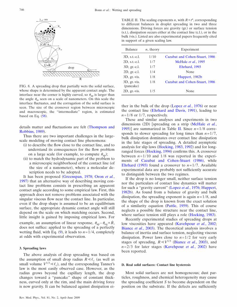
The situation is summarized in Fig. 8, which shows adrop of partially wetting fluid spreading on a solid sub-strate. Roughly speaking, the problem can be split upinto three distinct regions. First is the macroscopic flowin the drop on the scale of its radius R, often referred toas the “outer” region, in the language of asymptotic ex-pansions �Cox, 1986�. Second is the contact line region,characterized by a balance of viscous and surface ten-sion forces, over which the interface is strongly bent,resulting in a rapid change of the interface slope. This iscalled the “intermediate” region, whose size is estimatedas 3 Ca R /�ap, based on where the profile turns fromconcave to convex �see Sec. III.B below�. Third is an“inner” region, forming a neighborhood of the size ofnanometers around the contact line, where microscopic
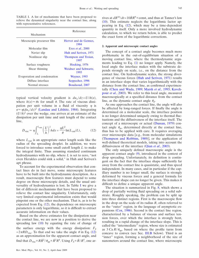
TABLE I. A list of mechanisms that have been proposed torelieve the dynamical singularity near the contact line, alongwith representative references.
MechanismReference
Mesoscopic precursor film Hervet and de Gennes,1984
Molecular film Eres et al., 2000Navier slip Huh and Scriven, 1971
Nonlinear slip Thompson and Troian,1997
Surface roughness Hocking, 1976Shear thinning Weidner and Schwartz,
1993Evaporation and condensation Wayner, 1993
Diffuse interface Seppecher, 1996Normal stresses Boudaoud, 2007
745Bonn et al.: Wetting and spreading
Rev. Mod. Phys., Vol. 81, No. 2, April–June 2009
details matter and fluctuations are felt �Thompson andRobbins, 1989�.
Thus there are two important challenges in the large-scale modeling of moving contact line phenomena:
�i� to describe the flow close to the contact line, and tounderstand its consequences for the flow problemon a large scale �for example, to compute �ap�;
�ii� to match the hydrodynamic part of the problem toa microscopic neighborhood of the contact line �ofthe size of a nanometer�, where a molecular de-scription needs to be adopted.
It has been proposed �Greenspan, 1978; Oron et al.,1997� that an alternative way of describing moving con-tact line problems consists in prescribing an apparentcontact angle according to some empirical law. First, thisapproach does not remove problems associated with thesingular viscous flow near the contact line. In particular,even if the drop shape is assumed to be an equilibriumsurface, the appropriate dynamic contact angle will stilldepend on the scale on which matching occurs. Second,little insight is gained by imposing empirical laws. For
example, an assumption of linear response, �ap−�eq R,does not suffice: applied to the spreading of a perfectlywetting fluid, with Eq. �9�, it leads to n=1/4, completelyat odds with experimental observation.
3. Spreading laws
The above analysis of drop spreading was based onthe assumption of small drop radius R �c �as well assmall volume V1/3 �c�, and the corresponding Tanner’slaw is the most easily observed case. However, as theradius grows beyond the capillary length, the dropchanges toward a “pancake” shape of constant thick-ness, curved only at the rim, and the main driving forceis now gravity. It can be balanced against dissipation ei-
ther in the bulk of the drop �Lopez et al., 1976� or nearthe contact line �Ehrhard and Davis, 1991�, leading ton=1/8 or 1/7, respectively.
These and similar analyses and experiments in twodimensions �2D� spreading on a strip �McHale et al.,1995�� are summarized in Table II. Since n=1/8 corre-sponds to slower spreading for long times than n=1/7,bulk dissipation dominates over contact line dissipationin the late stages of spreading. A detailed asymptoticanalysis for slip laws �Hocking, 1983, 1992� and for long-ranged forces �Hocking, 1994� confirms this. A crossoverbetween n=1/10 and 1/8 was reported in the experi-ments of Cazabat and Cohen-Stuart �1986�, whileEhrhard �1993� found a crossover to n=1/7. Availableexperimental data are probably not sufficiently accurateto distinguish between the two regimes.
If the drop is no longer small, neither surface tensionnor the particulars of contact line dynamics will matterfor such a “gravity current” �Lopez et al., 1976; Huppert,1982b�. As found from a balance of gravity and bulkdissipation, the spreading exponent is again n=1/8, andthe shape of the drop is known from the exact solutionof a similarity equation �Pattle, 1959�. This of courseneglects a possible fine structure near the contact line,where surface tension still plays a role �Hocking, 1983�.
Recently experimental studies of spreading drops atlow viscosities have appeared �Kavehpour et al., 2002;Biance et al., 2003�. The theoretical analysis involves abalance of inertia and surface tension, neglecting viscousdissipation. Power laws close to n=1/2 for very earlystages of spreading, R V1/3 �Biance et al., 2003�, andn=2/3 for later stages �Kavehpour et al., 2002� havebeen reported.
D. Real solid surfaces: Contact line hysteresis
Most solid surfaces are not homogeneous; dust par-ticles, roughness, and chemical heterogeneity may causethe spreading coefficient S to become dependent on theposition on the substrate. If the defects are sufficiently
� � � � � � � � �� � � � � � � � �� � � � � � � � �� � � � � � � � �� � � � � � � � �� � � � � � � � �
� � � � � � � � �� � � � � � � � �� � � � � � � � �
� � � � � � � � � � � � � � � � � � � � � � � � � � � �� � � � � � � � � � � � � � � � � � � � � � � � � � � �
� � � � � � � � � � � � � � � � � � � � � � � � � � � �
� � � � � � � � � � � � � � � � � � � � � � � � � � � �
drop
m
θ ap
θm
R
U=R
θap
θ
mλ ∼ nm
apθ
.
3CaR/
FIG. 8. A spreading drop that partially wets the solid surface,whose shape is determined by the apparent contact angle. Theinterface near the corner is highly curved, so �ap is larger thanthe angle �m seen on a scale of nanometers. On this scale theinterface fluctuates, and the corrugation of the solid surface isseen. The size of the crossover region between microscopicand macroscopic, the “intermediate” region, is estimatedbased on Eq. �58�.
TABLE II. The scaling exponents n, with R tn, correspondingto different balances in droplet spreading in two and threedimensions. Driving forces are gravity �gr.� or surface tension�s.t.�, dissipation occurs either at the contact line �c.l.�, or in thebulk �vis.�. Listed are also experimental papers frequently citedin support of a given scaling law.
Balance n, theory Experiment
3D, s.t.-c.l. 1 /10 Cazabat and Cohen-Stuart, 19862D, s.t.-c.l. 1 /7 McHale et al., 19953D, gr.-c.l. 1 /7 Ehrhard, 19932D, gr.-c.l. 1 /4 None3D, gr.-vis. 1 /8 Huppert, 1982b3D, gr.-vis.�pancake�
1/8 Cazabat and Cohen-Stuart, 1986
2D, gr.-vis. 1 /5 None
746 Bonn et al.: Wetting and spreading
Rev. Mod. Phys., Vol. 81, No. 2, April–June 2009
weak, one may hope that Young’s relation still holds,
provided that S is replaced by its mean value S, i.e., itsvalue averaged over the substrate area. This leads to theso-called Cassie-Baxter relation �Cassie, 1952�,
��1 − cos �CB� = − S , �13�
which allows us to define the contact angle of a liquid ona heterogeneous substrate. Very careful experimentswith a silicone wafer grafted with two different silanesshow that the cosine of the contact angle does indeedvary linearly with the surface density X of one of thecomponents, exactly as expected from Eq. �13� �Silber-zan et al., 1991�. However, Eq. �13� only makes sense ifthermodynamic equilibrium can be reached. This im-plies that the contact angle of a liquid drop deposited onthe substrate reaches a unique value �eq, independent ofthe way the droplet is deposited on the substrate. Thisonly very rarely happens in experiments, since even asmall heterogeneity of the substrate may lead to a sig-nificant hysteresis of the contact angle.
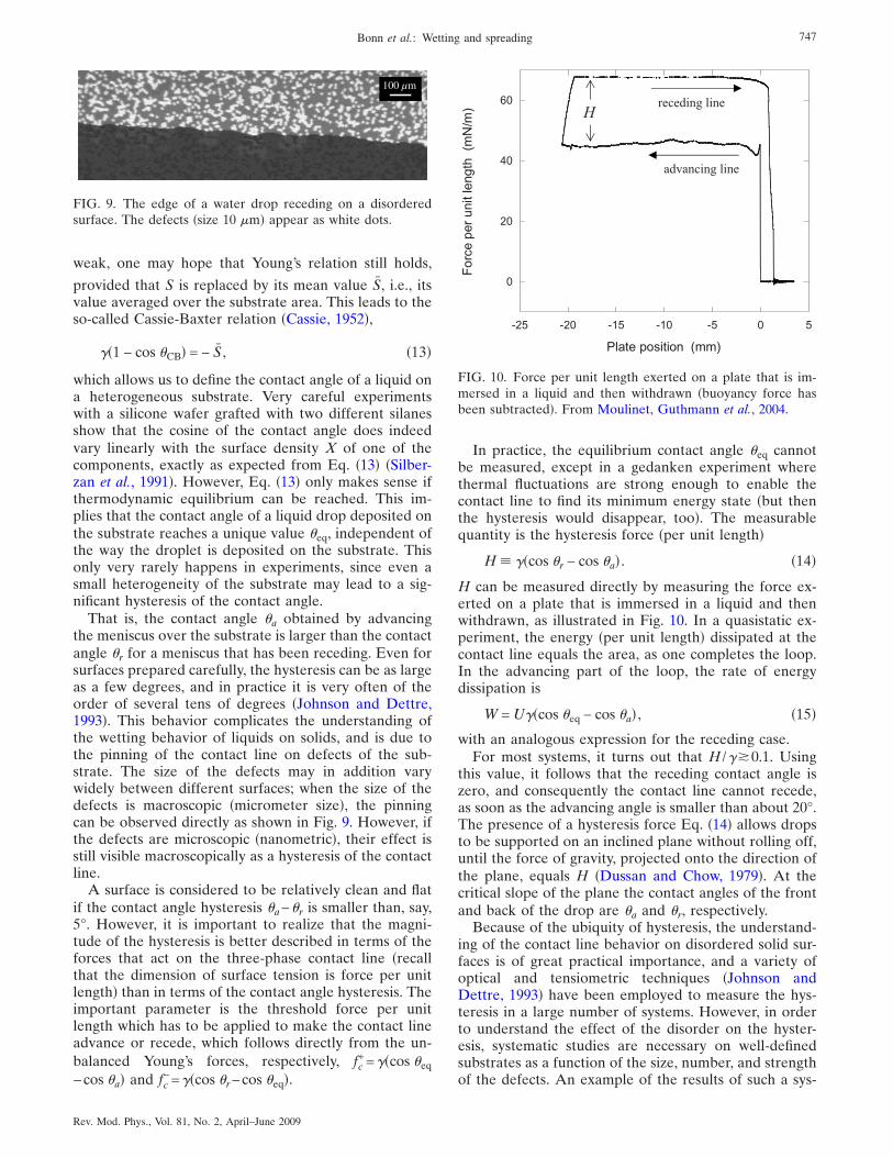
That is, the contact angle �a obtained by advancingthe meniscus over the substrate is larger than the contactangle �r for a meniscus that has been receding. Even forsurfaces prepared carefully, the hysteresis can be as largeas a few degrees, and in practice it is very often of theorder of several tens of degrees �Johnson and Dettre,1993�. This behavior complicates the understanding ofthe wetting behavior of liquids on solids, and is due tothe pinning of the contact line on defects of the sub-strate. The size of the defects may in addition varywidely between different surfaces; when the size of thedefects is macroscopic �micrometer size�, the pinningcan be observed directly as shown in Fig. 9. However, ifthe defects are microscopic �nanometric�, their effect isstill visible macroscopically as a hysteresis of the contactline.
A surface is considered to be relatively clean and flatif the contact angle hysteresis �a−�r is smaller than, say,5°. However, it is important to realize that the magni-tude of the hysteresis is better described in terms of theforces that act on the three-phase contact line �recallthat the dimension of surface tension is force per unitlength� than in terms of the contact angle hysteresis. Theimportant parameter is the threshold force per unitlength which has to be applied to make the contact lineadvance or recede, which follows directly from the un-balanced Young’s forces, respectively, fc
+=��cos �eq
−cos �a� and fc−=��cos �r−cos �eq�.
In practice, the equilibrium contact angle �eq cannotbe measured, except in a gedanken experiment wherethermal fluctuations are strong enough to enable thecontact line to find its minimum energy state �but thenthe hysteresis would disappear, too�. The measurablequantity is the hysteresis force �per unit length�
H � ��cos �r − cos �a� . �14�
H can be measured directly by measuring the force ex-erted on a plate that is immersed in a liquid and thenwithdrawn, as illustrated in Fig. 10. In a quasistatic ex-periment, the energy �per unit length� dissipated at thecontact line equals the area, as one completes the loop.In the advancing part of the loop, the rate of energydissipation is
W = U��cos �eq − cos �a� , �15�
with an analogous expression for the receding case.For most systems, it turns out that H /��0.1. Using
this value, it follows that the receding contact angle iszero, and consequently the contact line cannot recede,as soon as the advancing angle is smaller than about 20°.The presence of a hysteresis force Eq. �14� allows dropsto be supported on an inclined plane without rolling off,until the force of gravity, projected onto the direction ofthe plane, equals H �Dussan and Chow, 1979�. At thecritical slope of the plane the contact angles of the frontand back of the drop are �a and �r, respectively.
Because of the ubiquity of hysteresis, the understand-ing of the contact line behavior on disordered solid sur-faces is of great practical importance, and a variety ofoptical and tensiometric techniques �Johnson andDettre, 1993� have been employed to measure the hys-teresis in a large number of systems. However, in orderto understand the effect of the disorder on the hyster-esis, systematic studies are necessary on well-definedsubstrates as a function of the size, number, and strengthof the defects. An example of the results of such a sys-
100 µm
FIG. 9. The edge of a water drop receding on a disorderedsurface. The defects �size 10 �m� appear as white dots.
0
20
40
60
-25 -20 -15 -10 -5 0 5
Forceperunitlength(mN/m)
Plate position (mm)
Hreceding line
advancing line
FIG. 10. Force per unit length exerted on a plate that is im-mersed in a liquid and then withdrawn �buoyancy force hasbeen subtracted�. From Moulinet, Guthmann et al., 2004.
747Bonn et al.: Wetting and spreading
Rev. Mod. Phys., Vol. 81, No. 2, April–June 2009
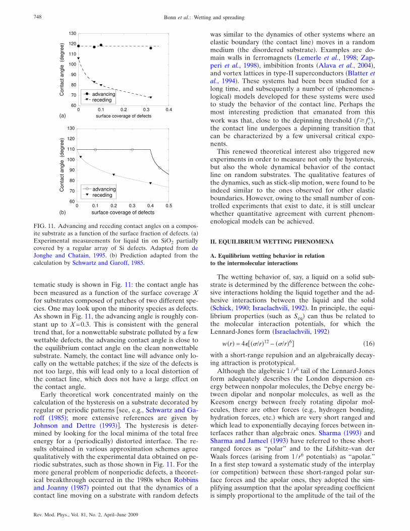
tematic study is shown in Fig. 11: the contact angle hasbeen measured as a function of the surface coverage Xfor substrates composed of patches of two different spe-cies. One may look upon the minority species as defects.As shown in Fig. 11, the advancing angle is roughly con-stant up to X=0.3. This is consistent with the generaltrend that, for a nonwettable substrate polluted by a fewwettable defects, the advancing contact angle is close tothe equilibrium contact angle on the clean nonwettablesubstrate. Namely, the contact line will advance only lo-cally on the wettable patches; if the size of the defects isnot too large, this will lead only to a local distortion ofthe contact line, which does not have a large effect onthe contact angle.
Early theoretical work concentrated mainly on thecalculation of the hysteresis on a substrate decorated byregular or periodic patterns see, e.g., Schwartz and Ga-roff �1985�; more extensive references are given byJohnson and Dettre �1993��. The hysteresis is deter-mined by looking for the local minima of the total freeenergy for a �periodically� distorted interface. The re-sults obtained in various approximation schemes agreequalitatively with the experimental data obtained on pe-riodic substrates, such as those shown in Fig. 11. For themore general problem of nonperiodic defects, a theoret-ical breakthrough occurred in the 1980s when Robbinsand Joanny �1987� pointed out that the dynamics of acontact line moving on a substrate with random defects
was similar to the dynamics of other systems where anelastic boundary �the contact line� moves in a randommedium �the disordered substrate�. Examples are do-main walls in ferromagnets �Lemerle et al., 1998; Zap-peri et al., 1998�, imbibition fronts �Alava et al., 2004�,and vortex lattices in type-II superconductors �Blatter etal., 1994�. These systems had been been studied for along time, and subsequently a number of �phenomeno-logical� models developed for these systems were usedto study the behavior of the contact line. Perhaps themost interesting prediction that emanated from thiswork was that, close to the depinning threshold �f� fc
+�,the contact line undergoes a depinning transition thatcan be characterized by a few universal critical expo-nents.
This renewed theoretical interest also triggered newexperiments in order to measure not only the hysteresis,but also the whole dynamical behavior of the contactline on random substrates. The qualitative features ofthe dynamics, such as stick-slip motion, were found to beindeed similar to the ones observed for other elasticboundaries. However, owing to the small number of con-trolled experiments that exist to date, it is still unclearwhether quantitative agreement with current phenom-enological models can be achieved.
II. EQUILIBRIUM WETTING PHENOMENA
A. Equilibrium wetting behavior in relationto the intermolecular interactions
The wetting behavior of, say, a liquid on a solid sub-strate is determined by the difference between the cohe-sive interactions holding the liquid together and the ad-hesive interactions between the liquid and the solid�Schick, 1990; Israelachvili, 1992�. In principle, the equi-librium properties �such as Seq� can thus be related tothe molecular interaction potentials, for which theLennard-Jones form �Israelachvili, 1992�
w�r� = 4���/r�12 − ��/r�6� �16�
with a short-range repulsion and an algebraically decay-ing attraction is prototypical.
Although the algebraic 1/r6 tail of the Lennard-Jonesform adequately describes the London dispersion en-ergy between nonpolar molecules, the Debye energy be-tween dipolar and nonpolar molecules, as well as theKeesom energy between freely rotating dipolar mol-ecules, there are other forces �e.g., hydrogen bonding,hydration forces, etc.� which are very short ranged andwhich lead to exponentially decaying forces between in-terfaces rather than algebraic ones. Sharma �1993� andSharma and Jameel �1993� have referred to these short-ranged forces as “polar” and to the Lifshitz–van derWaals forces �arising from 1/r6 potentials� as “apolar.”In a first step toward a systematic study of the interplay�or competition� between these short-ranged polar sur-face forces and the apolar ones, they adopted the sim-plifying assumption that the apolar spreading coefficientis simply proportional to the amplitude of the tail of the
(b)
(a)
FIG. 11. Advancing and receding contact angles on a compos-ite substrate as a function of the surface fraction of defects. �a�Experimental measurements for liquid tin on SiO2 partiallycovered by a regular array of Si defects. Adapted from deJonghe and Chatain, 1995. �b� Prediction adapted from thecalculation by Schwartz and Garoff, 1985.
748 Bonn et al.: Wetting and spreading
Rev. Mod. Phys., Vol. 81, No. 2, April–June 2009
net apolar interaction between interfaces. Using theYoung-Laplace and Navier-Stokes equations they thenrelated the stability properties of a thin adsorbed film tomacroscopic parameters of wetting such as the contactangle.
One quantifies the net effect of the interaction poten-tials on the wetting behavior by considering a liquid filmof thickness l on a solid substrate. If, for instance, theadhesive solid-liquid interactions are strong, the systemcan lower its free energy by increasing the distance be-tween the two surfaces. This leads to a net repulsiveforce per unit area between the solid-liquid and liquid-vapor interfaces, which is called the disjoining pressure��l� �de Feijter, 1988; Teletzke et al., 1988� and can bemeasured in experiment. Theoretically, it can be derivedfrom the so-called effective interface potential V�l�through
��l� = − dV�l�/dl , �17�
where
�SV�l� = � + �SL + V�l� �18�
is the excess free energy per unit area of the liquid film,and V����0. Surface excess free energies are well de-fined thermodynamically and can be calculated usingstatistical mechanics �Rowlinson and Widom, 1982�.
The long-time static, but nonequilibrium behavior ofnonvolatile adsorbates can also be described by Eq. �18�;cf. Sec. I.B. To see this, it suffices to appreciate that thepreviously introduced dry-substrate surface tension �S0and the initial spreading coefficient Si correspond to tak-ing the �→0 limit in Eq. �18�,
�S0 � �SV�0� and Si � V�0� . �19�
Now, in view of the volume conservation of nonvolatiledrops, the static film thickness after flattening, assumingSi�0, is governed not by minimizing V���, as would bethe case for an equilibrium film, but by minimizing thesurface free energy with the constraint. This leads to themodified condition �Brochard-Wyart et al., 1991; deGennes et al., 2003�
V��� − V�0��/� = dV���/d� , �20�
allowing the determination of the static thickness of theflattened drop through an elegant tangent rule in theplot of V���. Since the nonvolatile drop would ideallylike to spread over the entire dry substrate, but containsinsufficient material to do so, the compromise is a finitepancake, slightly thinner than the infinitely wide equilib-rium thin film �without volume constraint, i.e., for vola-tile liquids�.
If the disjoining pressure is known, the equilibriumwetting state can be predicted, but a calculation basedon first principles is difficult. Starting from Lennard-Jones potentials, density functional theory �DFT��Dietrich, 1988; Evans, 1990; Schick, 1990� in principleprovides a means of calculating the equilibrium wettingstate. DFT is based directly on microscopically specifiedmolecular interactions. Within mean-field theory, one at-
tempts to find the free energy of the system as a func-tional of the density profile ��r� alone. This is, however,difficult owing to the slow decay of, e.g., the Lennard-Jones potential w�r�. Thus, either some simplificationshave to be made or the problem has to be solved nu-merically. Quantitative predictions based on numericalsolutions of the full DFT that have been verified by ex-periment are so far limited to the wetting behavior ofsimple atoms or molecules �e.g., He� on simple sub-strates �e.g., Cs� at zero temperature �Cheng et al., 1993�.Considering only the 1/r6 van der Waals attractive tail ofw�r�, the disjoining pressure for large distances can becalculated explicitly. If in addition the spreading coeffi-cient is known �for instance, from the phenomenologicalCahn-Landau theory�, the wetting behavior can be pre-dicted.
The subtleties and strengths of an approach based onDFT are illustrated by derivations of an effective Hamil-tonian for liquid-vapor interfaces �Dietrich andNapiórkowski, 1991; Mecke and Dietrich, 1999;Napiórkowski and Dietrich, 1993�. Taking into accountonly bulk fluctuations, first an intrinsic density profile isobtained, and in the next step undulations of the inter-face position are described by a statistical theory forcapillary waves on all length scales. The result is a non-local and non-Gaussian functional of the interface con-figuration. From this the usually postulated �local� Hel-frich Hamiltonian can be deduced by a gradientexpansion, which, however, features divergent coeffi-cients for all but strictly finite-range interactions. If oneexpands, as is usually done, the Fourier transform of theHelfrich Hamiltonian in powers of the transverse mo-mentum q, one obtains an approximate wave-vector-dependent interfacial tension ��q�. However, the Gauss-ian approximation to the nonlocal interface Hamiltonianderived by Mecke and Dietrich �1999� leads to a formfor ��q� that is qualitatively different in the long capil-lary wavelength limit and agrees better with experimentson liquids with intermolecular dispersion forces �Mora etal., 2003�.
1. Long-range forces: The Hamaker constant
The van der Waals interaction w�r�1/r6 cf. Eq. �16��includes all intermolecular dipole-dipole, dipole-induceddipole, and induced dipole-induced dipole interactions.Performing a volume integral over all molecules presentin the two half spaces bounding the film one finds acorresponding decay ��l��A /6l3 �Israelachvili, 1992�,where the so-called Hamaker constant A gives the am-plitude of the interaction. In the “repulsive” case, inwhich the layer tends to thicken, we have A�0; notethat Israelachvili �1992� used a different sign conventionfor A.
At distances larger than the microscopic ones, Eq.�17� leads to an effective interaction energy
749Bonn et al.: Wetting and spreading
Rev. Mod. Phys., Vol. 81, No. 2, April–June 2009
V�l� =A
12l2 �21�
between the two surfaces bounding the wetting layer.Note that this is a truly long-range interface potential,and this is why van der Waals forces are considered tobe of long range in the context of wetting. Assumingpairwise additivity of the interactions, Hamaker �1937�showed that A can be directly related to the amplitudesof the substrate-liquid and liquid-liquid interaction tails.Below we report a more complete calculation of A �Dzy-aloshinskii et al., 1961�, although the numerical improve-ment over the original result of Hamaker �1937� is small.
To understand the effect of both long- and short-ranged interactions on the wetting behavior it is usefulto consider the relation �de Feijter, 1988�
Seq = lmin
�
��l�dl . �22�
The potential minimum at lmin essentially contains theinformation about the short-ranged forces, i.e., the con-tributions that remain when the interaction tails are cutoff.
Partial wetting corresponds to Seq�0; this prohibitsthe formation of a wetting layer, regardless of the sign ofA. If Seq=0 and A�0, a wetting layer will form, and wespeak of complete wetting. An intermediate state mayoccur under certain conditions if Seq�0 �it is not exactlyzero but slightly negative, as discussed in Sec. II.B.2� andA�0: this intermediate wetting state is characterized bya mesoscopic wetting film, and has been called frustratedcomplete wetting �Indekeu, Ragil, Bonn, et al., 1999; In-dekeu, Ragil, Broseta, et al., 1999�. In this case, the in-terface potential has two minima such as for a first-orderwetting transition see Fig. 13�a��, but the second mini-mum occurs at a finite rather than infinite wetting filmthickness.
The Hamaker constant is thus a key property for de-termining the wetting behavior, and can be calculatedexactly �Dzyaloshinskii et al., 1961� in terms of the di-electric properties of the three materials, which are char-acterized by their frequency-dependent polarizability. Inaddition, as explained below, the Hamaker constant isalso important in determining the spreading behavior.For its calculation, one has to integrate the dipolar in-teractions over all frequencies, and express them as aneffective interaction between the two surfaces boundingthe half spaces. A simple and usually good approxima-tion �Israelachvili, 1992� is obtained by first consideringthe contribution due to dipolar interactions, given by the�zero frequency� dielectric constants of the materials:
A�=0 = −34
kBT��1 − �3���2 − �3���1 + �3���2 + �3�
. �23�
Here 1 �solid� and 2 �vapor� denote the material in thetwo half spaces, and 3 �liquid� is the intermediate mate-rial. According to Eq. �23� �A�=0� can never exceed�3/4�kBT, but it is usually significantly smaller. As a re-sult, unless strongly polar molecules such as water are
involved, A�=0 can be neglected with respect to thefinite-frequency term that accounts for induced dipolarinteractions. The only case for which the static contribu-tion �23� is important is when at least one of the mate-rials has a high dielectric constant �e.g., water� and therefractive index differences in the visible are small; onepertinent example of both is the wetting of light hydro-carbons on water �Ragil, Meunier, et al., 1996�.
The main contribution to the integral comes from fre-quencies corresponding to visible light, and conse-quently A��0 is given by the refractive indices in thevisible:
A��0 = −3h�UV
16�2�n12 + n3
2��n22 + n3
2�
��n1
2 − n32��n2
2 − n32�
��n12 + n3
2� + ��n22 + n3
2�. �24�
Here h is Planck’s constant and �uv ��2�1016 Hz� is theuv frequency for which the refractive indices of the ma-terials become identical �close to unity�. The Hamakerconstant is the sum of the two contributions givenabove.
The zero-frequency or Keesom and/or Debye part ofthe Hamaker constant preserves the 1/ l2 dependence ofV�l� in Eq. �21� for all distances; however, the dispersiveor London part A��0 is subject to retardation, as inter-actions due to changing dipoles only travel at the speedof light. The typical frequency �uv corresponds to dis-tances of 15 nm; for larger distances the 1/ l2 behaviorcrosses over to a 1/ l3 decay. However, in general thecorrection from retardation is hardly detectable in ex-periment �Sabisky and Anderson, 1973�.
It also follows from Eq. �24� that, for a symmetricalsituation �two identical materials separated by a thirdand different material�, the net effect of the van derWaals forces is always an effective attraction betweenthe two interfaces �A�0�. Thus if only van der Waalsinteractions are important, two colloid particles are at-tracted to each other and colloids invariably flocculate.In a wetting problem the situation is different as in gen-eral three different materials are involved. In this case, itfollows from Eqs. �23� and �24� that depending on thedielectric properties of the three media A can have ei-ther sign.
For the typical case that A��0 dominates, the sign of Ais given by the sign of the refractive index differencebetween the liquid and the solid, since the refractive in-dex of the vapor will generally be close to unity. If theliquid has a refractive index between that of the solidand the vapor �which is usually the case�, it follows thatA�0 and the formation of a liquid wetting layer is fa-vored: there is an effective repulsion between the inter-faces. If �and only if� in addition the equilibrium spread-ing coefficient is zero, complete wetting will result.
For thick equilibrium wetting films, the van der Waalsinteractions and a possible gravitational penalty forforming a wetting layer above its bulk reservoir have to
750 Bonn et al.: Wetting and spreading
Rev. Mod. Phys., Vol. 81, No. 2, April–June 2009
be taken into account. This leads to �Deryaguin, 1940;de Gennes, 1981; Evans and Marini Bettolo Marconi,1985�
l = � A
6��gH�1/3
, �25�
where H is the height of the wetting layer above its bulkphase and �� is the mass density difference between thewetting layer and the phase on which it rests. Away fromTc, explicit calculation gives A /6�0.5kBT and thus l�100 Å, in general agreement with experiments on bi-nary liquid systems �Moldover and Cahn, 1980; Find-enegg and Löring, 1984; Kayser et al., 1986; Schmidt andMoldover, 1986; Law, 1991; Bonn et al., 1992�. For low-temperature systems Sabisky and Anderson �1973� con-firmed that lH−1/3 as predicted by Eq. �25�, where H isthe height above the reservoir. More generally H can beidentified as a chemical potential shift away from coex-istence: ��gH, giving
l ����−1/3. �26�
When a substrate is brought into contact with a nonsat-urated vapor, ��=kBT ln�P /Psat� and the liquid wettinglayer thickness diverges as coexistence is approached�Krim et al., 1984�.
Closer to Tc, the bulk correlation length can becomeof the order of the film thickness. A recent experimentalstudy �Fenistein et al., 2002� of the binary liquid mixturecyclohexane-methanol has shown that, upon approachto the bulk critical temperature, the film thickness di-
verges as t−� with an apparent effective critical exponent
�=0.23±0.06.
2. Short-range forces: The phenomenological Cahn-Landautheory of wetting
The classical theory of Cahn �1977�, combined with aLandau expansion, is an explicit way to calculate thespreading coefficient. In addition it does quite well inpredicting generic wetting behavior, in spite of the factthat the van der Waals tails of the intermolecular forcesare not included. For a detailed discussion of Cahn-Landau theory, see, e.g., Bonn and Ross �2001�. It can beused to predict first-order and short-range critical wet-ting transitions, and can be adapted when the tails of thevan der Waals forces control the wetting behavior, as isobserved for long-range critical wetting �Indekeu, Ragi,Bonn, et al., 1999�.
Cahn �1977� considered the surface free energy func-tional in a squared-gradient approximation, with the ad-dition of a surface term in order to account for the in-teractions with the wall:
Fs = ��ms� + 0
�
�c2/4��dm/dz�2 + ��m��dz , �27�
where � is the bulk free energy density, m�z� is the orderparameter profile as a function of the distance z fromthe wall, and ms�m�0� is its value at the substrate. For atypical adsorbed fluid m is proportional to the density
minus the critical density, �−�c. The term in the integralis the classical van der Waals form for a liquid-vaporinterface. It leads to an interface whose density profile isa hyperbolic tangent, and whose thickness is that of thebulk correlation length � �Rowlinson and Widom, 1982�.Cahn included a solid surface by adding the contact en-ergy ��ms� to Eq. �27� which depends only on ms. It isusually expanded to second order �Nakanishi and Fisher,1982�,
��ms� = − h1ms − gms2/2, �28�
where the parameters h1 and g are referred to as theshort-range surface field and the surface enhancement,respectively. The field h1 describes the preference of thesubstrate for either the liquid or the vapor, and is a mea-sure of the difference between the substrate-liquid andsubstrate-vapor surface tensions �Ross, Bonn, and Meu-nier, 2001�; consequently if h1�0, the liquid is preferredat the wall, whereas for h1�0 the vapor is preferred.The surface enhancement g allows for the missing inter-actions due to the fact that a particle near a wall has asmaller number of like neighbors than a particle in bulk.It is usually negative �Bonn and Ross, 2001�.
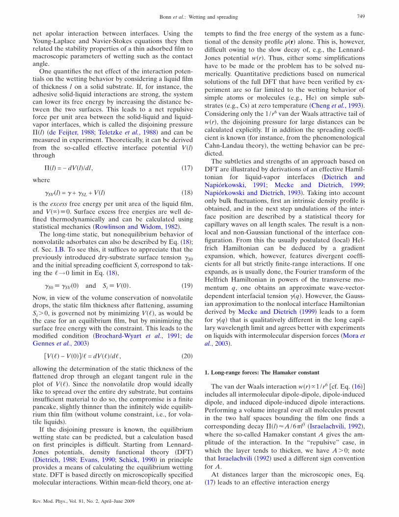
The phase diagram that follows from Cahn-Landautheory is illustrated in Fig. 12. We focus first on theplane h=0, which corresponds to the coexistence be-tween liquid and vapor, e.g., a drop sitting on a sub-strate. In fact, h���−�0� /kBT measures the distance inbulk chemical potential from two-phase coexistence.The remaining axes are the reduced temperature t= �T−Tc� /Tc and the surface field h1. In agreement withCahn’s expectation, upon increasing the temperature to-ward Tc one always leaves the hatched area bounded bythe so-called wetting line, and a wetting transition oc-curs. If h1 is large, the transition is of first order. How-
T
C
T t
h
T2nd order transition
1st order transition
W
complete wetting transition
complete drying transition
prewetting transition
h
1d
1pre
1w
c
partialwetting
1
FIG. 12. �Color online� The wetting phase diagram calculatedby Nakanishi and Fisher �1982�, where t= �T−Tc� /Tc is the re-duced temperature, h1 is the surface field, and h is the bulkfield. The wetting line W �which is a parabola in the mean fieldapproximation� has the critical temperature Tc at its apex. AtTw
1 there is a tricritical point which separates first-order fromsecond-order wetting transitions. The surface of prewettingtransitions is bounded by a line of critical points Cpre
1 , calledthe critical prewetting line, which merges into the wetting lineat Tw
1 .
751Bonn et al.: Wetting and spreading
Rev. Mod. Phys., Vol. 81, No. 2, April–June 2009
ever, as one crosses the tricritical point at Tw1 the transi-
tion becomes second order or critical.One interesting prediction of the Cahn-Landau theory
see also Ebner and Saam �1977�� is that a first-orderwetting transition at coexistence should persist in re-gions of the phase diagram off of coexistence h�0. Asshown in Fig. 12, this prewetting transition is an exten-sion of the wetting transition in the one-phase region ofthe bulk phase diagram. It manifests itself by the forma-tion of a thick �but not macroscopic� liquid film on thesubstrate at pressures below the saturated vapor pres-sure.
As one moves away from the wetting line, the line ofprewetting transitions ends in a surface critical point,called the prewetting critical point. Upon approach ofthe surface tricritical point Tw
1 , the prewetting lineshrinks progressively away; for critical wetting there isno prewetting line �cf. Fig. 12�. As one approaches coex-istence for T�Tw, the wetting temperature, one ob-serves complete wetting, characterized by a wetting filmwhose thickness diverges. These transitions, includingthe prewetting line and its critical point, have been ob-served experimentally. Thus, although phenomenologi-cal and without direct link to the intermolecular interac-tions, the Cahn-Landau theory is an excellent startingpoint for understanding wetting transitions, and is oftenused as a tool in engineering applications to predict wet-ting behavior �Carey et al., 1978�.
However, de Gennes �1983�, Ebner and Saam �1987�,and others have shown that, generically, van der Waalsforces eliminate the possibility of critical wetting. A con-cise discussion has been given by Indekeu, Ragil, Bonn,et al. �1999�. Below we indicate how this can be recon-ciled with experiment �see Sec. II.B.2�. When van derWaals forces oppose wetting, a first-order thin-thicktransition may still persist, but a macroscopic wettinglayer cannot form. Instead, at the first-order transition, amesoscopic film forms �typically 50–100 Å in experi-ments� �Ragil, Meunier, et al., 1996; Shahidzadeh et al.,1998; Bertrand, Bonn, Broseta, et al., 2002�. Remarkably,in this frustrated complete wetting state a droplet placedon a substrate displays a tiny but finite contact angle andcoexists with a mesoscopic film.
B. Real systems: Three scenarios for wetting transitions
Much of the progress in the study of wetting transi-tions over the past decade has been experimental, usingtwo key systems: low-temperature liquid-vapor systemsand room-temperature binary liquid systems. The twohave provided almost identical results—highlighting therobustness of the phenomena of wetting transitions overorders of magnitude of temperature and interactionstrengths.
For solid-liquid systems, work on the low-temperaturesystems was motivated by the prediction �Cheng et al.,1991� that liquid helium would not wet surfaces of theheavier alkali metals at very low temperatures, andtherefore, according to the Cahn argument �see Sec.II.C.1 below�, that wetting transitions should be ob-
served in these systems. This prediction, and the subse-quent experimental verification of the partial wetting ofhelium on cesium �Nacher and Dupont-Roc, 1991� atlow temperatures initiated a large amount of wetting re-search with quantum liquids on weak-binding alkali-metal substrates; for recent reviews, see Cheng et al.�1993�, Bruch et al. �1997�, and Bonn and Ross �2001�.
This increased activity resulted, among other things,in the first experimental verification �Rutledge andTaborek, 1992� theoretically predicted prewetting line�Cahn, 1977; Ebner and Saam, 1977�. An advantage ofthe low-temperature systems is the simplicity of the in-teraction potentials, so that detailed comparisons withDFT �Cheng et al., 1993� are possible. The main disad-vantage is the roughness and chemical inhomogeneity ofthe alkali substrates, leading to pinning of the contactline, and to poor reproducibility �Klier et al., 1995; Rol-ley and Guthmann, 1997; Ross et al., 1998� and ratherlarge uncertainties for instance in the measured contactangles. The effects of disorder will be discussed in detailin Sec. IV.
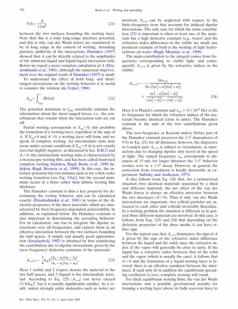
A schematic interface potential V�l� for a first-order�discontinuous� transition and for a second-order �con-tinuous or critical� transition is shown in Fig. 13. In gen-eral, complete wetting is more likely to occur at highertemperatures. For a first-order wetting transition, thiscorresponds to a discontinuous jump from a thin film�partial wetting� to an infinitely thick film �complete wet-ting�: for low T the absolute minimum in V�l� is the thinfilm, for high T it is the infinitely thick film. At the first-order wetting temperature, the free energy of the twominima is equal. For a continuous transition, there isonly one minimum, and this minimum shifts continu-
(b)
(a)
FIG. 13. �Color online� Schematic effective interface potentialfor a first-order wetting transition �a� and for a �short-range�critical wetting transition �b�.
752 Bonn et al.: Wetting and spreading
Rev. Mod. Phys., Vol. 81, No. 2, April–June 2009
ously to an infinitely thick film upon reaching the criticalwetting temperature.
1. First-order and critical wetting
A simple argument, due to Cahn �1977�, uses Young’sequation to argue that a wetting transition should alwaysoccur as the bulk critical point is approached by lettingT→Tc. Indeed, for the majority of systems studied todate a wetting transition is encountered upon increasingthe temperature towards the critical point, and tempera-ture is the most used control parameter to study wettingtransitions. A demonstration of this principle of critical-point wetting is the transition from partial to completewetting of the interface between the upper and lowerphases by the middle phase microemulsion, when ap-proaching either the upper or the lower critical endpoint in H2O-octane-C5E2 �C5E2 is diethylene glycol-pentylalcohol� liquid mixtures �Kahlweit et al., 1993�.
Note that the Cahn argument foresees only one kindof transition: a first-order wetting transition, in whichthe wetting layer appears on a substrate, or at an inter-face, in a discontinuous fashion, again in line with themajority of experimental observations. However, a care-ful analysis reveals that the Cahn argument actuallybreaks down for T→Tc �Pandit et al., 1982; Sullivan andTelo da Gama, 1986; Indekeu 1991; Bonn and Ross,2001�, hence the argument cannot be used too close tothe bulk critical point. Experimentally, the wetting tran-sition actually turns second order �continuous� close tothe bulk critical point, as predicted by the Cahn-Landautheory.
Two �independent� critical exponents characterize thewetting transition. First, the manner in which cos �eq ap-proaches 1 at the wetting temperature defines the sur-face specific heat exponent �s through �Dietrich, 1988;Schick, 1990�
�1 − cos �eq� �Tw − T�2−�s. �29�
For �s=1, the first derivative of �SV with respect to thetemperature is discontinuous at Tw �cos �eq=1 for T�Tw� and so the wetting transition is of first order. For�s�1, the first derivative is continuous at Tw: the tran-sition is a continuous or critical wetting transition.
Second, the divergence of the layer thickness l is de-scribed by
l �Tw − T��s. �30�
Note that �s�0.Because of the difficulties of working with solid sur-
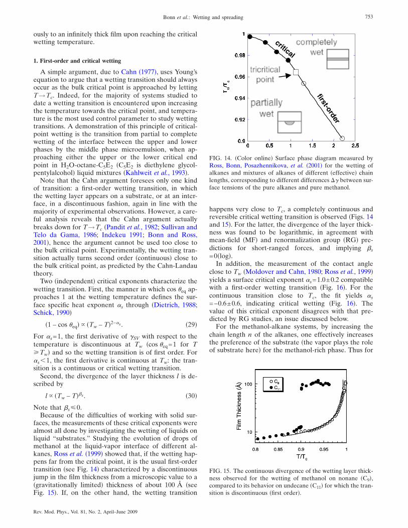
faces, the measurements of these critical exponents werealmost all done by investigating the wetting of liquids onliquid “substrates.” Studying the evolution of drops ofmethanol at the liquid-vapor interface of different al-kanes, Ross et al. �1999� showed that, if the wetting hap-pens far from the critical point, it is the usual first-ordertransition �see Fig. 14� characterized by a discontinuousjump in the film thickness from a microscopic value to a�gravitationally limited� thickness of about 100 Å �seeFig. 15�. If, on the other hand, the wetting transition
happens very close to Tc, a completely continuous andreversible critical wetting transition is observed �Figs. 14and 15�. For the latter, the divergence of the layer thick-ness was found to be logarithmic, in agreement withmean-field �MF� and renormalization group �RG� pre-dictions for short-ranged forces, and implying �s=0�log�.
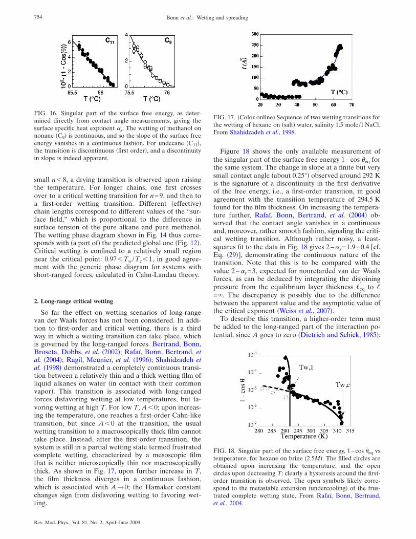
In addition, the measurement of the contact angleclose to Tw �Moldover and Cahn, 1980; Ross et al., 1999�yields a surface critical exponent �s=1.0±0.2 compatiblewith a first-order wetting transition �Fig. 16�. For thecontinuous transition close to Tc, the fit yields �s=−0.6±0.6, indicating critical wetting �Fig. 16�. Thevalue of this critical exponent disagrees with that pre-dicted by RG studies, an issue discussed below.
For the methanol-alkane systems, by increasing thechain length n of the alkanes, one effectively increasesthe preference of the substrate �the vapor plays the roleof substrate here� for the methanol-rich phase. Thus for
FIG. 14. �Color online� Surface phase diagram measured byRoss, Bonn, Posazhennikova, et al. �2001� for the wetting ofalkanes and mixtures of alkanes of different �effective� chainlengths, corresponding to different differences �� between sur-face tensions of the pure alkanes and pure methanol.
FIG. 15. The continuous divergence of the wetting layer thick-ness observed for the wetting of methanol on nonane �C9�,compared to its behavior on undecane �C11� for which the tran-sition is discontinuous �first order�.
753Bonn et al.: Wetting and spreading
Rev. Mod. Phys., Vol. 81, No. 2, April–June 2009
small n�8, a drying transition is observed upon raisingthe temperature. For longer chains, one first crossesover to a critical wetting transition for n=9, and then toa first-order wetting transition. Different �effective�chain lengths correspond to different values of the “sur-face field,” which is proportional to the difference insurface tension of the pure alkane and pure methanol.The wetting phase diagram shown in Fig. 14 thus corre-sponds with �a part of� the predicted global one �Fig. 12�.Critical wetting is confined to a relatively small regionnear the critical point: 0.97�Tw /Tc�1, in good agree-ment with the generic phase diagram for systems withshort-ranged forces, calculated in Cahn-Landau theory.
2. Long-range critical wetting
So far the effect on wetting scenarios of long-rangevan der Waals forces has not been considered. In addi-tion to first-order and critical wetting, there is a thirdway in which a wetting transition can take place, whichis governed by the long-ranged forces. Bertrand, Bonn,Broseta, Dobbs, et al. �2002�; Rafaï, Bonn, Bertrand, etal. �2004�; Ragil, Meunier, et al. �1996�; Shahidzadeh etal. �1998� demonstrated a completely continuous transi-tion between a relatively thin and a thick wetting film ofliquid alkanes on water �in contact with their commonvapor�. This transition is associated with long-rangedforces disfavoring wetting at low temperatures, but fa-voring wetting at high T. For low T, A�0; upon increas-ing the temperature, one reaches a first-order Cahn-liketransition, but since A�0 at the transition, the usualwetting transition to a macroscopically thick film cannottake place. Instead, after the first-order transition, thesystem is still in a partial wetting state termed frustratedcomplete wetting, characterized by a mesoscopic filmthat is neither microscopically thin nor macroscopicallythick. As shown in Fig. 17, upon further increase in T,the film thickness diverges in a continuous fashion,which is associated with A→0; the Hamaker constantchanges sign from disfavoring wetting to favoring wet-ting.
Figure 18 shows the only available measurement ofthe singular part of the surface free energy 1−cos �eq forthe same system. The change in slope at a finite but verysmall contact angle �about 0.25°� observed around 292 Kis the signature of a discontinuity in the first derivativeof the free energy, i.e., a first-order transition, in goodagreement with the transition temperature of 294.5 Kfound for the film thickness. On increasing the tempera-ture further, Rafaï, Bonn, Bertrand, et al. �2004� ob-served that the contact angle vanishes in a continuousand, moreover, rather smooth fashion, signaling the criti-cal wetting transition. Although rather noisy, a least-squares fit to the data in Fig. 18 gives 2−�s=1.9±0.4 cf.Eq. �29��, demonstrating the continuous nature of thetransition. Note that this is to be compared with thevalue 2−�s=3, expected for nonretarded van der Waalsforces, as can be deduced by integrating the disjoiningpressure from the equilibrium layer thickness �eq to �=�. The discrepancy is possibly due to the differencebetween the apparent value and the asymptotic value ofthe critical exponent �Weiss et al., 2007�.
To describe this transition, a higher-order term mustbe added to the long-ranged part of the interaction po-tential, since A goes to zero �Dietrich and Schick, 1985�:
FIG. 16. Singular part of the surface free energy, as deter-mined directly from contact angle measurements, giving thesurface specific heat exponent �s. The wetting of methanol onnonane �C9� is continuous, and so the slope of the surface freeenergy vanishes in a continuous fashion. For undecane �C11�,the transition is discontinuous �first order�, and a discontinuityin slope is indeed apparent.
FIG. 17. �Color online� Sequence of two wetting transitions forthe wetting of hexane on �salt� water, salinity 1.5 mole/ l NaCl.From Shahidzadeh et al., 1998.
FIG. 18. Singular part of the surface free energy, 1−cos �eq vstemperature, for hexane on brine �2.5M�. The filled circles areobtained upon increasing the temperature, and the opencircles upon decreasing T: clearly a hysteresis around the first-order transition is observed. The open symbols likely corre-spond to the metastable extension �undercooling� of the frus-trated complete wetting state. From Rafaï, Bonn, Bertrand,et al., 2004.
754 Bonn et al.: Wetting and spreading
Rev. Mod. Phys., Vol. 81, No. 2, April–June 2009
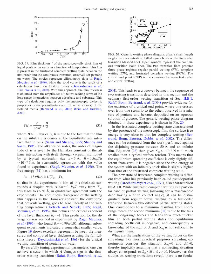
V�l� =A
12l2 +B
l3 , �31�
where B�0. Physically, B is due to the fact that the filmon the substrate is denser at the liquid/substrate inter-face than in bulk �Saam and Shenoy, 1995; Shenoy andSaam, 1995�. For alkanes on water, the order of magni-tude of B is given by the Hamaker constant of the al-kane interacting with itself through vacuum, multipliedby a typical molecular size a�5 Å, B�0.5kBTa�10−30 J m, in reasonable agreement with the valuefound in experiment �Ragil, Meunier, et al., 1996�. Thefree energy �31� has a minimum for
l = − 18B/A 1/�Tw − T� , �32�
so that in the experiments a film of this thickness sur-rounds a droplet; with A /6�0.1kBT away from Tw,this leads to l�50 Å, in qualitative agreement with theexperiments. The continuous divergence of the wettingfilm happens as the Hamaker constant, the only forcethat prevents wetting, goes to zero linearly at the wet-ting temperature �Dietrich and Schick, 1985; Ragil,Meunier, et al., 1996�; this defines the critical exponentof the layer thickness �s=−1. This prediction for the di-vergence was verified in experiment by Ragil, Meunier,et al. �1996�, who found �s=−0.99±0.05, although subse-quent experiments indicated a somewhat smaller value.Figure 19 shows excellent agreement between the mea-sured and computed layer thicknesses using the full Lif-shitz theory �Dzyaloshinskii et al., 1961� for the criticalwetting transition of pentane on water.
By carefully tuning experimental parameters, one canachieve a system in which A changes sign at the first-order wetting transition �Rafaï, Bonn, Bertrand, et al.,
2004�. This leads to a crossover between the sequence oftwo wetting transitions described in this section and theordinary first-order wetting transition of Sec. II.B.1.Rafaï, Bonn, Bertrand, et al. �2004� provide evidence forthe existence of a critical end point, where one crossesover from one scenario to the other, observed in a mix-ture of pentane and hexane, deposited on an aqueoussolution of glucose. The generic wetting phase diagramobtained in these experiments is shown in Fig. 20.
In the frustrated complete wetting state characterizedby the presence of the mesoscopic film, the surface freeenergy is very close to that for complete wetting �Ber-trand, Bonn, Broseta, Dobbs, et al., 2002�. The differ-ence can be estimated from the work performed againstthe disjoining pressure between 50 Å and an infinitefilm. Equation �22� then gives Seq�−10−6 N m−1, muchsmaller than a typical surface tension. This means thatthe equilibrium spreading coefficient is only slightly dif-ferent from zero: it is negative since the free energy ofthe system with an infinitely thick film is slightly higherthan that of the frustrated complete wetting state.
The new state of frustrated complete wetting is differ-ent from what has previously been called pseudopartialwetting �Brochard-Wyart et al., 1991�, also characterizedby A�0. While frustrated complete wetting is a particu-lar case of partial wetting �allowing for a macroscopicdrop having a finite contact angle�, it can be distin-guished from regular partial wetting by a first-ordertransition between two different partial wetting states.One corresponds to a minimum resulting from short-range forces; the second minimum �32� is due to the tailsof the long-range forces and leads to a much thickerfilm. In both partial wetting states the equilibriumspreading coefficient is negative, and consequently aknowledge of the sign of A and Seq is not sufficient todistinguish them.
What are the implications of the wetting forces on thespreading? For most practical purposes spreading ex-periments consider the situation Seq=0 and A�0,thereby implicitly assuming that a nonwetting situationalways corresponds to Seq�0 and A�0. However, as thestudies on wetting transitions reveal, there is no funda-
300 305 310 315 320 325T [K]
0
20
40
60
80
100
120
l[nm
]
FIG. 19. Film thickness l of the mesoscopically thick film ofliquid pentane on water as a function of temperature. This filmis present in the frustrated complete wetting state between thefirst-order and the continuous transition, observed for pentaneon water. The circles represent ellipsometry data of Ragil,Meunier, et al. �1996�, while the solid curve is the result of acalculation based on Lifshitz theory �Dzyaloshinskii et al.,1961; Weiss et al., 2007�. With this approach, the film thicknessis obtained from the amplitudes of the two leading terms of thelong-range interactions between adsorbate and substrate. Thistype of calculation requires only the macroscopic dielectricproperties �static permittivities and refractive indices� of theisolated media �Bertrand et al., 2001; Weiss and Indekeu,2003�.
FIG. 20. Generic wetting phase diagram: alkane chain lengthvs glucose concentration. Filled symbols show the first-ordertransition �dashed line�. Open symbols represent the continu-ous transition �solid line�. The two transition lines producethree phase regions: regular partial wetting �PW�, completewetting �CW�, and frustrated complete wetting �FCW�. Thecritical end point �CEP� is the crossover between first orderand critical wetting.
755Bonn et al.: Wetting and spreading
Rev. Mod. Phys., Vol. 81, No. 2, April–June 2009
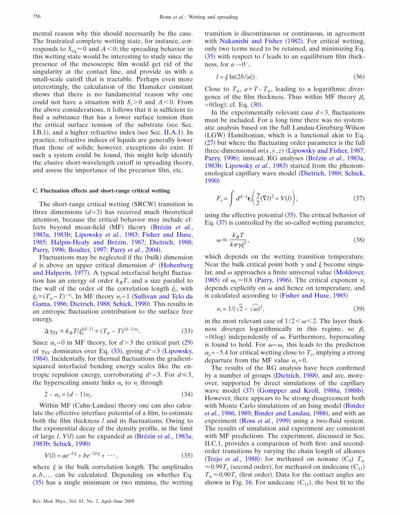
mental reason why this should necessarily be the case.The frustrated complete wetting state, for instance, cor-responds to Seq�0 and A�0; the spreading behavior inthis wetting state would be interesting to study since thepresence of the mesoscopic film would get rid of thesingularity at the contact line, and provide us with asmall-scale cutoff that is tractable. Perhaps even moreinterestingly, the calculation of the Hamaker constantshows that there is no fundamental reason why onecould not have a situation with Si�0 and A�0. Fromthe above considerations, it follows that it is sufficient tofind a substance that has a lower surface tension thanthe critical surface tension of the substrate �see Sec.I.B.1�, and a higher refractive index �see Sec. II.A.1�. Inpractice, refractive indices of liquids are generally lowerthan those of solids; however, exceptions do exist. Ifsuch a system could be found, this might help identifythe elusive short-wavelength cutoff in spreading theory,and assess the importance of the precursor film, etc.
C. Fluctuation effects and short-range critical wetting
The short-range critical wetting �SRCW� transition inthree dimensions �d=3� has received much theoreticalattention, because the critical behavior may include ef-fects beyond mean-field �MF� theory �Brézin et al.,1983a, 1983b; Lipowsky et al., 1983; Fisher and Huse,1985; Halpin-Healy and Brézin, 1987; Dietrich, 1988;Parry, 1996; Boulter, 1997; Parry et al., 2004�.
Fluctuations may be neglected if the �bulk� dimensiond is above an upper critical dimension d* �Hohenbergand Halperin, 1977�. A typical interfacial height fluctua-tion has an energy of order kBT, and a size parallel tothe wall of the order of the correlation length ��, with�� �Tw−T�−��. In MF theory �� =1 �Sullivan and Telo daGama, 1986; Dietrich, 1988; Schick, 1990�. This results inan entropic fluctuation contribution to the surface freeenergy,
��SV kBT/���d−1� �Tw − T��d−1��� . �33�
Since �s=0 in MF theory, for d�3 the critical part �29�of �SV dominates over Eq. �33�, giving d*=3 �Lipowsky,1984�. Incidentally, for thermal fluctuations the gradient-squared interfacial bending energy scales like the en-tropic repulsion energy, corroborating d*=3. For d�3,the hyperscaling ansatz links �s to �� through
2 − �s = �d − 1��� . �34�
Within MF �Cahn-Landau� theory one can also calcu-late the effective interface potential of a film, to estimateboth the film thickness l and its fluctuations. Owing tothe exponential decay of the density profile, in the limitof large l, V�l� can be expanded as �Brézin et al., 1983a,1983b; Schick, 1990�
V�l� = ae−l/� + be−2l/� + ¯ , �35�
where � is the bulk correlation length. The amplitudesa ,b , . . . can be calculated. Depending on whether Eq.�35� has a single minimum or two minima, the wetting
transition is discontinuous or continuous, in agreementwith Nakanishi and Fisher �1982�. For critical wetting,only two terms need to be retained, and minimizing Eq.�35� with respect to l leads to an equilibrium film thick-ness, for a→0−,
l = � ln�2b/�a�� . �36�
Close to Tw, aT−Tw, leading to a logarithmic diver-gence of the film thickness. Thus within MF theory �s=0�log�; cf. Eq. �30�.
In the experimentally relevant case d=3, fluctuationsmust be included. For a long time there was no system-atic analysis based on the full Landau-Ginzburg-Wilson�LGW� Hamiltonian, which is a functional akin to Eq.�27� but where the fluctuating order parameter is the fullthree-dimensional m�x ,y ,z� �Lipowsky and Fisher, 1987;Parry, 1996�; instead, RG analyses �Brézin et al., 1983a,1983b; Lipowsky et al., 1983� started from the phenom-enological capillary wave model �Dietrich, 1988; Schick,1990�
Fs = dd−1r���2
��l�2 + V�l�� , �37�
using the effective potential �35�. The critical behavior ofEq. �37� is controlled by the so-called wetting parameter,
� �kBT
4��2 , �38�
which depends on the wetting transition temperature.Near the bulk critical point both � and � become singu-lar, and � approaches a finite universal value �Moldover,1985� of �c�0.8 �Parry, 1996�. The critical exponent ��
depends explicitly on � and hence on temperature, andis calculated according to �Fisher and Huse, 1985�
�� = 1/��2 − ���2, �39�
in the most relevant case of 1/2���2. The layer thick-ness diverges logarithmically in this regime, so �s=0�log� independently of �. Furthermore, hyperscalingis found to hold. For �=�c this leads to the prediction�s=−5.4 for critical wetting close to Tc, implying a strongdeparture from the MF value �s=0.
The results of the RG analysis have been confirmedby a number of groups �Dietrich, 1988�, and are, more-over, supported by direct simulations of the capillarywave model �37� �Gompper and Kroll, 1988a, 1988b�.However, there appears to be strong disagreement bothwith Monte Carlo simulations of an Ising model �Binderet al., 1986, 1989; Binder and Landau, 1988�, and with anexperiment �Ross et al., 1999� using a two-fluid system.The results of simulation and experiment are consistentwith MF predictions. The experiment, discussed in Sec.II.C.1, provides a comparison of both first- and second-order transitions by varying the chain length of alkanes�Trejo et al., 1988�: for methanol on nonane �C9� Tw�0.99Tc �second order�, for methanol on undecane �C11�Tw�0.90Tc �first order�. Data for the contact angles areshown in Fig. 16. For undecane �C11�, the best fit to the
756 Bonn et al.: Wetting and spreading
Rev. Mod. Phys., Vol. 81, No. 2, April–June 2009
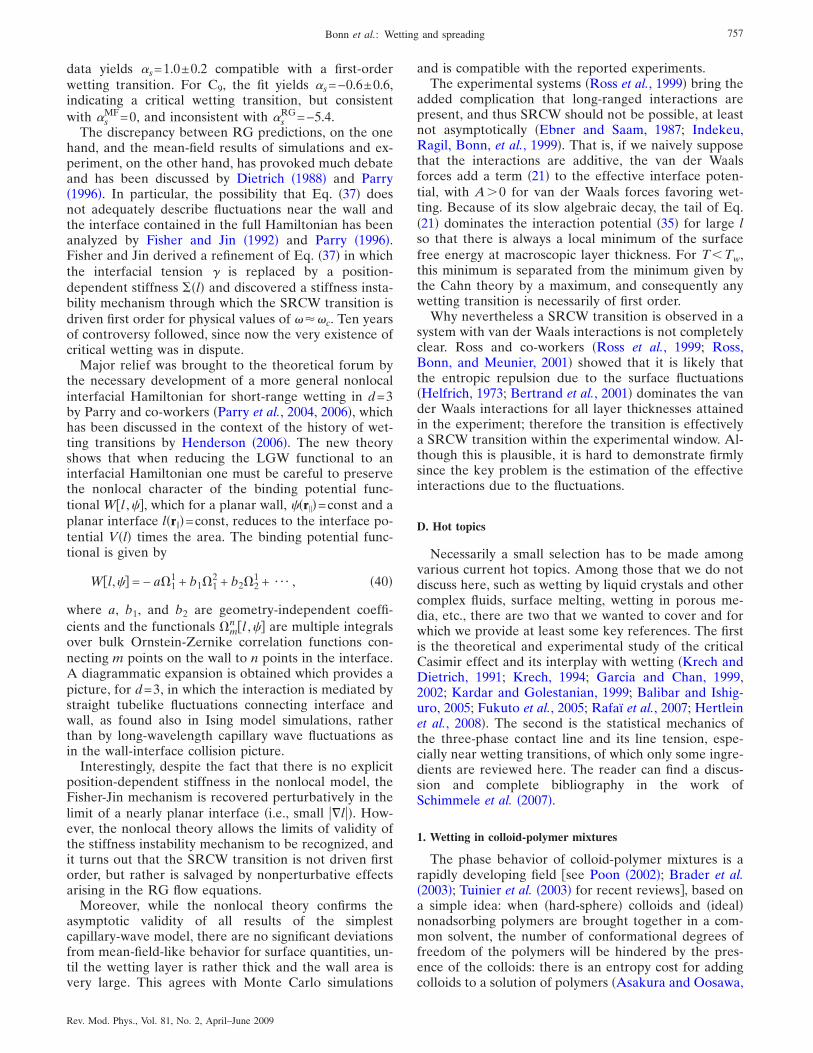
data yields �s=1.0±0.2 compatible with a first-orderwetting transition. For C9, the fit yields �s=−0.6±0.6,indicating a critical wetting transition, but consistentwith �s
MF=0, and inconsistent with �sRG=−5.4.
The discrepancy between RG predictions, on the onehand, and the mean-field results of simulations and ex-periment, on the other hand, has provoked much debateand has been discussed by Dietrich �1988� and Parry�1996�. In particular, the possibility that Eq. �37� doesnot adequately describe fluctuations near the wall andthe interface contained in the full Hamiltonian has beenanalyzed by Fisher and Jin �1992� and Parry �1996�.Fisher and Jin derived a refinement of Eq. �37� in whichthe interfacial tension � is replaced by a position-dependent stiffness ��l� and discovered a stiffness insta-bility mechanism through which the SRCW transition isdriven first order for physical values of ���c. Ten yearsof controversy followed, since now the very existence ofcritical wetting was in dispute.
Major relief was brought to the theoretical forum bythe necessary development of a more general nonlocalinterfacial Hamiltonian for short-range wetting in d=3by Parry and co-workers �Parry et al., 2004, 2006�, whichhas been discussed in the context of the history of wet-ting transitions by Henderson �2006�. The new theoryshows that when reducing the LGW functional to aninterfacial Hamiltonian one must be careful to preservethe nonlocal character of the binding potential func-tional Wl ,��, which for a planar wall, ��r��=const and aplanar interface l�r��=const, reduces to the interface po-tential V�l� times the area. The binding potential func-tional is given by
Wl,�� = − a�11 + b1�1
2 + b2�21 + ¯ , �40�
where a, b1, and b2 are geometry-independent coeffi-cients and the functionals �m
n l ,�� are multiple integralsover bulk Ornstein-Zernike correlation functions con-necting m points on the wall to n points in the interface.A diagrammatic expansion is obtained which provides apicture, for d=3, in which the interaction is mediated bystraight tubelike fluctuations connecting interface andwall, as found also in Ising model simulations, ratherthan by long-wavelength capillary wave fluctuations asin the wall-interface collision picture.
Interestingly, despite the fact that there is no explicitposition-dependent stiffness in the nonlocal model, theFisher-Jin mechanism is recovered perturbatively in thelimit of a nearly planar interface �i.e., small ��l��. How-ever, the nonlocal theory allows the limits of validity ofthe stiffness instability mechanism to be recognized, andit turns out that the SRCW transition is not driven firstorder, but rather is salvaged by nonperturbative effectsarising in the RG flow equations.
Moreover, while the nonlocal theory confirms theasymptotic validity of all results of the simplestcapillary-wave model, there are no significant deviationsfrom mean-field-like behavior for surface quantities, un-til the wetting layer is rather thick and the wall area isvery large. This agrees with Monte Carlo simulations
and is compatible with the reported experiments.The experimental systems �Ross et al., 1999� bring the
added complication that long-ranged interactions arepresent, and thus SRCW should not be possible, at leastnot asymptotically �Ebner and Saam, 1987; Indekeu,Ragil, Bonn, et al., 1999�. That is, if we naively supposethat the interactions are additive, the van der Waalsforces add a term �21� to the effective interface poten-tial, with A�0 for van der Waals forces favoring wet-ting. Because of its slow algebraic decay, the tail of Eq.�21� dominates the interaction potential �35� for large lso that there is always a local minimum of the surfacefree energy at macroscopic layer thickness. For T�Tw,this minimum is separated from the minimum given bythe Cahn theory by a maximum, and consequently anywetting transition is necessarily of first order.
Why nevertheless a SRCW transition is observed in asystem with van der Waals interactions is not completelyclear. Ross and co-workers �Ross et al., 1999; Ross,Bonn, and Meunier, 2001� showed that it is likely thatthe entropic repulsion due to the surface fluctuations�Helfrich, 1973; Bertrand et al., 2001� dominates the vander Waals interactions for all layer thicknesses attainedin the experiment; therefore the transition is effectivelya SRCW transition within the experimental window. Al-though this is plausible, it is hard to demonstrate firmlysince the key problem is the estimation of the effectiveinteractions due to the fluctuations.
D. Hot topics
Necessarily a small selection has to be made amongvarious current hot topics. Among those that we do notdiscuss here, such as wetting by liquid crystals and othercomplex fluids, surface melting, wetting in porous me-dia, etc., there are two that we wanted to cover and forwhich we provide at least some key references. The firstis the theoretical and experimental study of the criticalCasimir effect and its interplay with wetting �Krech andDietrich, 1991; Krech, 1994; Garcia and Chan, 1999,2002; Kardar and Golestanian, 1999; Balibar and Ishig-uro, 2005; Fukuto et al., 2005; Rafaï et al., 2007; Hertleinet al., 2008�. The second is the statistical mechanics ofthe three-phase contact line and its line tension, espe-cially near wetting transitions, of which only some ingre-dients are reviewed here. The reader can find a discus-sion and complete bibliography in the work ofSchimmele et al. �2007�.
1. Wetting in colloid-polymer mixtures
The phase behavior of colloid-polymer mixtures is arapidly developing field see Poon �2002�; Brader et al.�2003�; Tuinier et al. �2003� for recent reviews�, based ona simple idea: when �hard-sphere� colloids and �ideal�nonadsorbing polymers are brought together in a com-mon solvent, the number of conformational degrees offreedom of the polymers will be hindered by the pres-ence of the colloids: there is an entropy cost for addingcolloids to a solution of polymers �Asakura and Oosawa,
757Bonn et al.: Wetting and spreading
Rev. Mod. Phys., Vol. 81, No. 2, April–June 2009
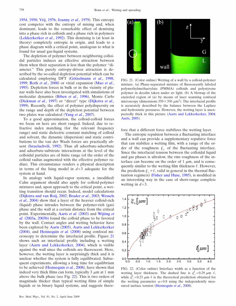
1954, 1958; Vrij, 1976; Joanny et al., 1979�. This entropycost competes with the entropy of mixing and, whendominant, leads to the remarkable effect of demixinginto a phase rich in colloids and a phase rich in polymers�Lekkerkerker et al., 1992�. This demixing is �at least intheory� completely entropic in origin, and leads to aphase diagram with a critical point, analogous to what isfound for usual gas-liquid systems.
The depletion of polymer between neighboring colloi-dal particles induces an effective attraction betweenthem when their separation is less than the polymer “di-ameter.” This purely entropy-driven attraction is de-scribed by the so-called depletion potential which can becalculated employing DFT �Götzelmann et al., 1998,1999; Roth et al., 2000� or virial expansion �Mao et al.,1995�. Depletion forces in bulk or in the vicinity of pla-nar walls have also been investigated with simulations ofmolecular dynamics �Biben et al., 1996�, Monte Carlo�Dickman et al., 1997� or “direct” type �Dijkstra et al.,1999�. Recently, the effect of polymer polydispersity onthe range and depth of the depletion potential betweentwo plates was calculated �Yang et al., 2007�.
To a good approximation, the colloid-colloid forceswe focus on here are short ranged. Indeed, due to re-fractive index matching �for the relevant frequencyrange� and static dielectric constant matching of colloidand solvent, the dynamic �dispersion� and static contri-butions to the van der Waals forces are practically ab-sent �Israelachvili, 1992�. Thus all adsorbate-adsorbateand adsorbate-substrate interactions at the level of thecolloidal particles are of finite range �of the order of thecolloid radius augmented with the effective polymer ra-dius�. This circumstance renders a physical descriptionin terms of the Ising model in d=3 adequate for thesystem at hand.
In analogy with liquid-vapor systems, a �modified�Cahn argument should also apply for colloid-polymermixtures and, upon approach to the critical point, a wet-ting transition should occur. Indeed, model calculations�Dijkstra and van Roij, 2002; Brader et al., 2003; Wesselset al., 2004� show that a layer of the heavier colloid-rich�liquid� phase intrudes between the polymer-rich �gas�phase and the wall at a certain distance from the criticalpoint. Experimentally, Aarts et al. �2003� and Wijting etal. �2003a, 2003b� found the colloid phase to be favoredby the wall. Contact angles and wetting behavior havebeen explored by Aarts �2005�, Aarts and Lekkerkerker�2004�, and Hennequin et al. �2008� using confocal mi-croscopy to determine the interfacial profile. Figure 21shows such an interfacial profile including a wettinglayer �Aarts and Lekkerkerker, 2004�, which is visibleagainst the wall since the colloids are fluorescent. Here,however, the wetting layer is surprisingly thick and it isunclear whether the system is fully equilibrated. Subse-quent experiments, allowing a long time for equilibriumto be achieved �Hennequin et al., 2008�, have shown thatindeed very thick films can form, typically 3 �m at 1 mmabove the bulk phase �see Fig. 22�. This is two orders ofmagnitude thicker than typical wetting films of simpleliquids or in binary liquid systems, and suggests there-
fore that a different force stabilizes the wetting layer.The entropic repulsion between a fluctuating interface
and a wall can provide a supplementary repulsive forcethat can stabilize a wetting film, with a range of the or-der of the roughness �� of the fluctuating interface.Since the interfacial tension between the colloidal liquidand gas phases is ultralow, the rms roughness of the in-terface can become on the order of 1 �m, and is conse-quently similar to the wetting film thickness �. However,the prediction ���, valid in general in the thermal fluc-tuation regime�s� �Fisher and Huse, 1985�, is modified inan interesting way in the case of short-range completewetting in d=3.
FIG. 21. �Color online� Wetting of a wall by a colloid-polymermixture. �a� Phase-separated mixture of fluorescently labeledpolymethylmethacrylate �PMMA� colloids and polystyrenepolymer in decalin taken under uv light. �b� A blowup of theencircled region of �a� by means of laser scanning confocalmicroscopy �dimensions 350�350 �m2�. The interfacial profileis accurately described by the balance between the Laplaceand hydrostatic pressures. However, the wetting layer is unex-pectedly thick in this picture �Aarts and Lekkerkerker, 2004;Aarts, 2005�.
FIG. 22. �Color online� Interface width as a function of thewetting layer thickness. The dashed line is ��
2 =0.29 �m �,while ��
2 =0.23 �m � is the theoretical prediction obtained forthe wetting parameter �=0.8 using the independently mea-sured surface tension �Hennequin et al., 2008�.
758 Bonn et al.: Wetting and spreading
Rev. Mod. Phys., Vol. 81, No. 2, April–June 2009
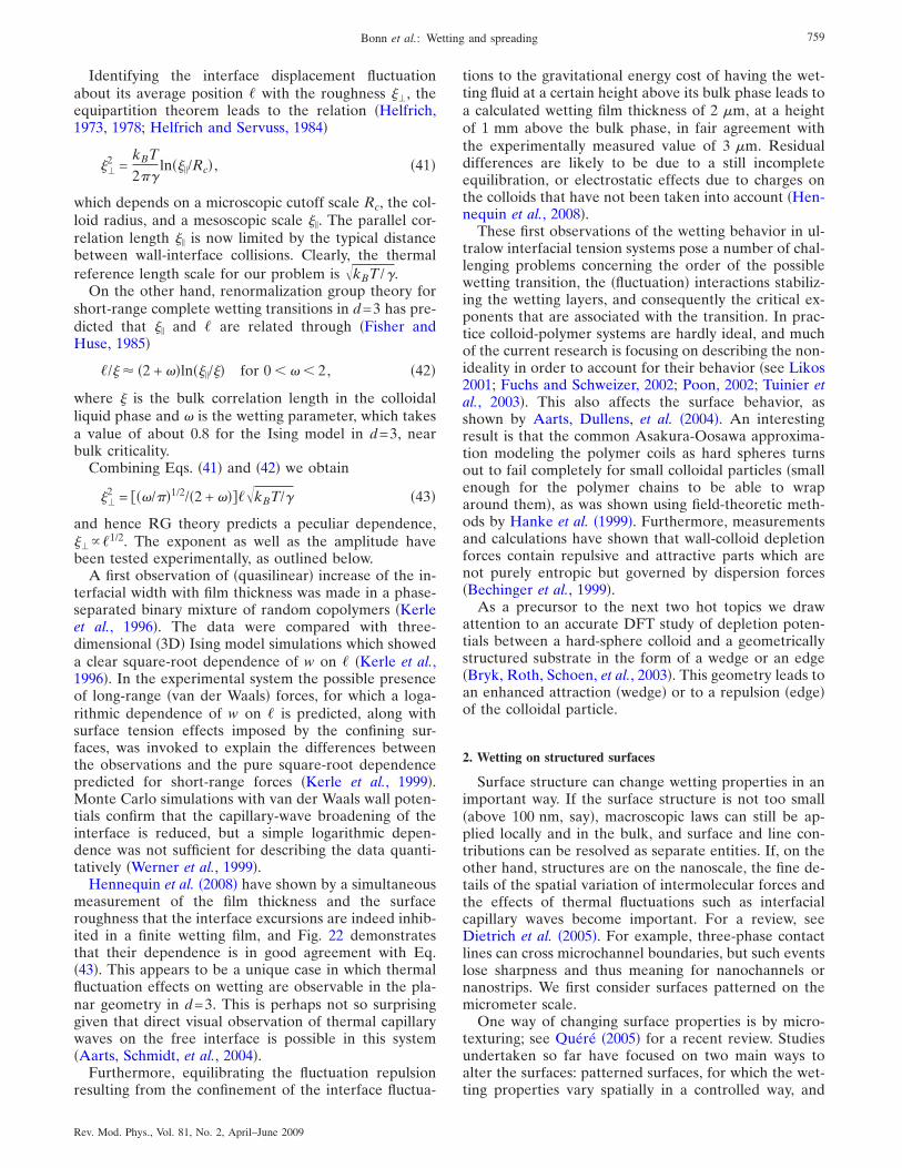
Identifying the interface displacement fluctuationabout its average position � with the roughness ��, theequipartition theorem leads to the relation �Helfrich,1973, 1978; Helfrich and Servuss, 1984�
��2 =
kBT
2�ln���/Rc� , �41�
which depends on a microscopic cutoff scale Rc, the col-loid radius, and a mesoscopic scale ��. The parallel cor-relation length �� is now limited by the typical distancebetween wall-interface collisions. Clearly, the thermalreference length scale for our problem is �kBT /�.
On the other hand, renormalization group theory forshort-range complete wetting transitions in d=3 has pre-dicted that �� and � are related through �Fisher andHuse, 1985�
�/� � �2 + ��ln���/�� for 0 ��� 2, �42�
where � is the bulk correlation length in the colloidalliquid phase and � is the wetting parameter, which takesa value of about 0.8 for the Ising model in d=3, nearbulk criticality.
Combining Eqs. �41� and �42� we obtain
��2 = ��/�1/2/�2 + �����kBT/� �43�
and hence RG theory predicts a peculiar dependence,���1/2. The exponent as well as the amplitude havebeen tested experimentally, as outlined below.
A first observation of �quasilinear� increase of the in-terfacial width with film thickness was made in a phase-separated binary mixture of random copolymers �Kerleet al., 1996�. The data were compared with three-dimensional �3D� Ising model simulations which showeda clear square-root dependence of w on � �Kerle et al.,1996�. In the experimental system the possible presenceof long-range �van der Waals� forces, for which a loga-rithmic dependence of w on � is predicted, along withsurface tension effects imposed by the confining sur-faces, was invoked to explain the differences betweenthe observations and the pure square-root dependencepredicted for short-range forces �Kerle et al., 1999�.Monte Carlo simulations with van der Waals wall poten-tials confirm that the capillary-wave broadening of theinterface is reduced, but a simple logarithmic depen-dence was not sufficient for describing the data quanti-tatively �Werner et al., 1999�.
Hennequin et al. �2008� have shown by a simultaneousmeasurement of the film thickness and the surfaceroughness that the interface excursions are indeed inhib-ited in a finite wetting film, and Fig. 22 demonstratesthat their dependence is in good agreement with Eq.�43�. This appears to be a unique case in which thermalfluctuation effects on wetting are observable in the pla-nar geometry in d=3. This is perhaps not so surprisinggiven that direct visual observation of thermal capillarywaves on the free interface is possible in this system�Aarts, Schmidt, et al., 2004�.
Furthermore, equilibrating the fluctuation repulsionresulting from the confinement of the interface fluctua-
tions to the gravitational energy cost of having the wet-ting fluid at a certain height above its bulk phase leads toa calculated wetting film thickness of 2 �m, at a heightof 1 mm above the bulk phase, in fair agreement withthe experimentally measured value of 3 �m. Residualdifferences are likely to be due to a still incompleteequilibration, or electrostatic effects due to charges onthe colloids that have not been taken into account �Hen-nequin et al., 2008�.
These first observations of the wetting behavior in ul-tralow interfacial tension systems pose a number of chal-lenging problems concerning the order of the possiblewetting transition, the �fluctuation� interactions stabiliz-ing the wetting layers, and consequently the critical ex-ponents that are associated with the transition. In prac-tice colloid-polymer systems are hardly ideal, and muchof the current research is focusing on describing the non-ideality in order to account for their behavior �see Likos2001; Fuchs and Schweizer, 2002; Poon, 2002; Tuinier etal., 2003�. This also affects the surface behavior, asshown by Aarts, Dullens, et al. �2004�. An interestingresult is that the common Asakura-Oosawa approxima-tion modeling the polymer coils as hard spheres turnsout to fail completely for small colloidal particles �smallenough for the polymer chains to be able to wraparound them�, as was shown using field-theoretic meth-ods by Hanke et al. �1999�. Furthermore, measurementsand calculations have shown that wall-colloid depletionforces contain repulsive and attractive parts which arenot purely entropic but governed by dispersion forces�Bechinger et al., 1999�.
As a precursor to the next two hot topics we drawattention to an accurate DFT study of depletion poten-tials between a hard-sphere colloid and a geometricallystructured substrate in the form of a wedge or an edge�Bryk, Roth, Schoen, et al., 2003�. This geometry leads toan enhanced attraction �wedge� or to a repulsion �edge�of the colloidal particle.
2. Wetting on structured surfaces
Surface structure can change wetting properties in animportant way. If the surface structure is not too small�above 100 nm, say�, macroscopic laws can still be ap-plied locally and in the bulk, and surface and line con-tributions can be resolved as separate entities. If, on theother hand, structures are on the nanoscale, the fine de-tails of the spatial variation of intermolecular forces andthe effects of thermal fluctuations such as interfacialcapillary waves become important. For a review, seeDietrich et al. �2005�. For example, three-phase contactlines can cross microchannel boundaries, but such eventslose sharpness and thus meaning for nanochannels ornanostrips. We first consider surfaces patterned on themicrometer scale.
One way of changing surface properties is by micro-texturing; see Quéré �2005� for a recent review. Studiesundertaken so far have focused on two main ways toalter the surfaces: patterned surfaces, for which the wet-ting properties vary spatially in a controlled way, and
759Bonn et al.: Wetting and spreading
Rev. Mod. Phys., Vol. 81, No. 2, April–June 2009
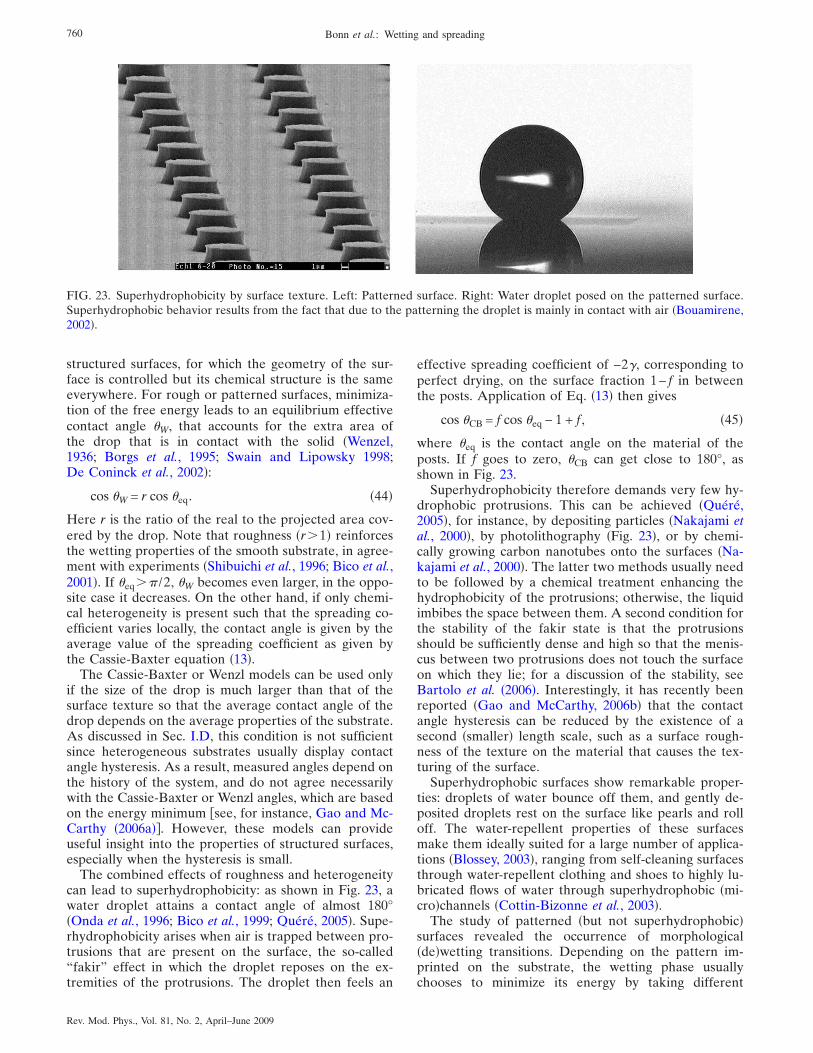
structured surfaces, for which the geometry of the sur-face is controlled but its chemical structure is the sameeverywhere. For rough or patterned surfaces, minimiza-tion of the free energy leads to an equilibrium effectivecontact angle �W, that accounts for the extra area ofthe drop that is in contact with the solid �Wenzel,1936; Borgs et al., 1995; Swain and Lipowsky 1998;De Coninck et al., 2002�:
cos �W = r cos �eq. �44�
Here r is the ratio of the real to the projected area cov-ered by the drop. Note that roughness �r�1� reinforcesthe wetting properties of the smooth substrate, in agree-ment with experiments �Shibuichi et al., 1996; Bico et al.,2001�. If �eq� /2, �W becomes even larger, in the oppo-site case it decreases. On the other hand, if only chemi-cal heterogeneity is present such that the spreading co-efficient varies locally, the contact angle is given by theaverage value of the spreading coefficient as given bythe Cassie-Baxter equation �13�.
The Cassie-Baxter or Wenzl models can be used onlyif the size of the drop is much larger than that of thesurface texture so that the average contact angle of thedrop depends on the average properties of the substrate.As discussed in Sec. I.D, this condition is not sufficientsince heterogeneous substrates usually display contactangle hysteresis. As a result, measured angles depend onthe history of the system, and do not agree necessarilywith the Cassie-Baxter or Wenzl angles, which are basedon the energy minimum see, for instance, Gao and Mc-Carthy �2006a��. However, these models can provideuseful insight into the properties of structured surfaces,especially when the hysteresis is small.
The combined effects of roughness and heterogeneitycan lead to superhydrophobicity: as shown in Fig. 23, awater droplet attains a contact angle of almost 180°�Onda et al., 1996; Bico et al., 1999; Quéré, 2005�. Supe-rhydrophobicity arises when air is trapped between pro-trusions that are present on the surface, the so-called“fakir” effect in which the droplet reposes on the ex-tremities of the protrusions. The droplet then feels an
effective spreading coefficient of −2�, corresponding toperfect drying, on the surface fraction 1− f in betweenthe posts. Application of Eq. �13� then gives
cos �CB = f cos �eq − 1 + f , �45�
where �eq is the contact angle on the material of theposts. If f goes to zero, �CB can get close to 180°, asshown in Fig. 23.
Superhydrophobicity therefore demands very few hy-drophobic protrusions. This can be achieved �Quéré,2005�, for instance, by depositing particles �Nakajami etal., 2000�, by photolithography �Fig. 23�, or by chemi-cally growing carbon nanotubes onto the surfaces �Na-kajami et al., 2000�. The latter two methods usually needto be followed by a chemical treatment enhancing thehydrophobicity of the protrusions; otherwise, the liquidimbibes the space between them. A second condition forthe stability of the fakir state is that the protrusionsshould be sufficiently dense and high so that the menis-cus between two protrusions does not touch the surfaceon which they lie; for a discussion of the stability, seeBartolo et al. �2006�. Interestingly, it has recently beenreported �Gao and McCarthy, 2006b� that the contactangle hysteresis can be reduced by the existence of asecond �smaller� length scale, such as a surface rough-ness of the texture on the material that causes the tex-turing of the surface.
Superhydrophobic surfaces show remarkable proper-ties: droplets of water bounce off them, and gently de-posited droplets rest on the surface like pearls and rolloff. The water-repellent properties of these surfacesmake them ideally suited for a large number of applica-tions �Blossey, 2003�, ranging from self-cleaning surfacesthrough water-repellent clothing and shoes to highly lu-bricated flows of water through superhydrophobic �mi-cro�channels �Cottin-Bizonne et al., 2003�.
The study of patterned �but not superhydrophobic�surfaces revealed the occurrence of morphological�de�wetting transitions. Depending on the pattern im-printed on the substrate, the wetting phase usuallychooses to minimize its energy by taking different
FIG. 23. Superhydrophobicity by surface texture. Left: Patterned surface. Right: Water droplet posed on the patterned surface.Superhydrophobic behavior results from the fact that due to the patterning the droplet is mainly in contact with air �Bouamirene,2002�.
760 Bonn et al.: Wetting and spreading
Rev. Mod. Phys., Vol. 81, No. 2, April–June 2009
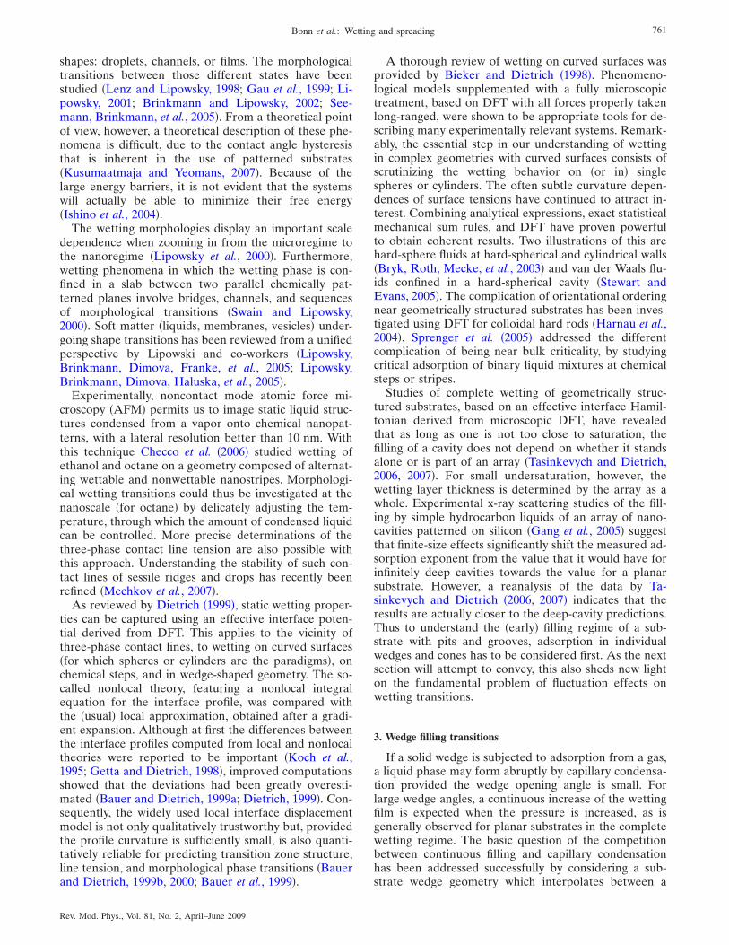
shapes: droplets, channels, or films. The morphologicaltransitions between those different states have beenstudied �Lenz and Lipowsky, 1998; Gau et al., 1999; Li-powsky, 2001; Brinkmann and Lipowsky, 2002; See-mann, Brinkmann, et al., 2005�. From a theoretical pointof view, however, a theoretical description of these phe-nomena is difficult, due to the contact angle hysteresisthat is inherent in the use of patterned substrates�Kusumaatmaja and Yeomans, 2007�. Because of thelarge energy barriers, it is not evident that the systemswill actually be able to minimize their free energy�Ishino et al., 2004�.
The wetting morphologies display an important scaledependence when zooming in from the microregime tothe nanoregime �Lipowsky et al., 2000�. Furthermore,wetting phenomena in which the wetting phase is con-fined in a slab between two parallel chemically pat-terned planes involve bridges, channels, and sequencesof morphological transitions �Swain and Lipowsky,2000�. Soft matter �liquids, membranes, vesicles� under-going shape transitions has been reviewed from a unifiedperspective by Lipowski and co-workers �Lipowsky,Brinkmann, Dimova, Franke, et al., 2005; Lipowsky,Brinkmann, Dimova, Haluska, et al., 2005�.
Experimentally, noncontact mode atomic force mi-croscopy �AFM� permits us to image static liquid struc-tures condensed from a vapor onto chemical nanopat-terns, with a lateral resolution better than 10 nm. Withthis technique Checco et al. �2006� studied wetting ofethanol and octane on a geometry composed of alternat-ing wettable and nonwettable nanostripes. Morphologi-cal wetting transitions could thus be investigated at thenanoscale �for octane� by delicately adjusting the tem-perature, through which the amount of condensed liquidcan be controlled. More precise determinations of thethree-phase contact line tension are also possible withthis approach. Understanding the stability of such con-tact lines of sessile ridges and drops has recently beenrefined �Mechkov et al., 2007�.
As reviewed by Dietrich �1999�, static wetting proper-ties can be captured using an effective interface poten-tial derived from DFT. This applies to the vicinity ofthree-phase contact lines, to wetting on curved surfaces�for which spheres or cylinders are the paradigms�, onchemical steps, and in wedge-shaped geometry. The so-called nonlocal theory, featuring a nonlocal integralequation for the interface profile, was compared withthe �usual� local approximation, obtained after a gradi-ent expansion. Although at first the differences betweenthe interface profiles computed from local and nonlocaltheories were reported to be important �Koch et al.,1995; Getta and Dietrich, 1998�, improved computationsshowed that the deviations had been greatly overesti-mated �Bauer and Dietrich, 1999a; Dietrich, 1999�. Con-sequently, the widely used local interface displacementmodel is not only qualitatively trustworthy but, providedthe profile curvature is sufficiently small, is also quanti-tatively reliable for predicting transition zone structure,line tension, and morphological phase transitions �Bauerand Dietrich, 1999b, 2000; Bauer et al., 1999�.
A thorough review of wetting on curved surfaces wasprovided by Bieker and Dietrich �1998�. Phenomeno-logical models supplemented with a fully microscopictreatment, based on DFT with all forces properly takenlong-ranged, were shown to be appropriate tools for de-scribing many experimentally relevant systems. Remark-ably, the essential step in our understanding of wettingin complex geometries with curved surfaces consists ofscrutinizing the wetting behavior on �or in� singlespheres or cylinders. The often subtle curvature depen-dences of surface tensions have continued to attract in-terest. Combining analytical expressions, exact statisticalmechanical sum rules, and DFT have proven powerfulto obtain coherent results. Two illustrations of this arehard-sphere fluids at hard-spherical and cylindrical walls�Bryk, Roth, Mecke, et al., 2003� and van der Waals flu-ids confined in a hard-spherical cavity �Stewart andEvans, 2005�. The complication of orientational orderingnear geometrically structured substrates has been inves-tigated using DFT for colloidal hard rods �Harnau et al.,2004�. Sprenger et al. �2005� addressed the differentcomplication of being near bulk criticality, by studyingcritical adsorption of binary liquid mixtures at chemicalsteps or stripes.
Studies of complete wetting of geometrically struc-tured substrates, based on an effective interface Hamil-tonian derived from microscopic DFT, have revealedthat as long as one is not too close to saturation, thefilling of a cavity does not depend on whether it standsalone or is part of an array �Tasinkevych and Dietrich,2006, 2007�. For small undersaturation, however, thewetting layer thickness is determined by the array as awhole. Experimental x-ray scattering studies of the fill-ing by simple hydrocarbon liquids of an array of nano-cavities patterned on silicon �Gang et al., 2005� suggestthat finite-size effects significantly shift the measured ad-sorption exponent from the value that it would have forinfinitely deep cavities towards the value for a planarsubstrate. However, a reanalysis of the data by Ta-sinkevych and Dietrich �2006, 2007� indicates that theresults are actually closer to the deep-cavity predictions.Thus to understand the �early� filling regime of a sub-strate with pits and grooves, adsorption in individualwedges and cones has to be considered first. As the nextsection will attempt to convey, this also sheds new lighton the fundamental problem of fluctuation effects onwetting transitions.
3. Wedge filling transitions
If a solid wedge is subjected to adsorption from a gas,a liquid phase may form abruptly by capillary condensa-tion provided the wedge opening angle is small. Forlarge wedge angles, a continuous increase of the wettingfilm is expected when the pressure is increased, as isgenerally observed for planar substrates in the completewetting regime. The basic question of the competitionbetween continuous filling and capillary condensationhas been addressed successfully by considering a sub-strate wedge geometry which interpolates between a
761Bonn et al.: Wetting and spreading
Rev. Mod. Phys., Vol. 81, No. 2, April–June 2009
planar substrate and a capillary slit �Rascón and Parry,2000b�. In this model the substrate height varies as apower law �x��, where x runs perpendicular to the wedge.For �=1 the familiar linear wedge is obtained, for whicha preliminary results were obtained prior to 2000 byPomeau �1986�, Cheng and Cole �1990�, Hauge �1992�,and Napiórkowski et al. �1992�. Hauge observed that thewetting transition in a wedge is shifted downward intemperature to the point where the contact angle equalsthe tilt angle. He then discussed the continuous �or first-order� character of the transition away from bulk two-phase coexistence �or at coexistence� using macroscopicarguments. Since this work, wedge wetting has becomeinteresting, not only as a tool to study wetting on struc-tured surfaces, but also as a problem in itself. Beforegoing into individual results, we stress the correspon-dence between interface statistical mechanics andgeometry that governs wedge filling, as elucidated byHenderson �2004a, 2004b�. This has provided a set ofexact sum rules linking fluid structure and surface freeenergy, of direct relevance to computer simulations andsignificant to the filling transitions discussed here.
If we focus for a moment on realistic systems with vander Waals forces, Rascón and Parry �2000a, 2000b� es-tablished that the approach to complete wetting in awedge is characterized by novel critical exponents whichare geometry dependent for ��1/2, while for ��1/2wedge filling is controlled by the singularities pertainingto complete wetting on a planar substrate. Interestingly,in the geometry-dominated regime, which includes theusual linear wedge, the critical exponents are universalwith respect to the exponent associated with the rangeof the intermolecular forces. Several of these predictionshave been verified experimentally. Bruschi and co-workers �Bruschi et al., 2001, 2002; Bruschi, Carlin,Parry, et al., 2003� measured the adsorption of mainlyliquid Ar �but also Kr� on an array of linear wedges andobserved the theoretically predicted crossover in thecritical exponent of the excess adsorbed mass from pla-nar to geometry-dominated behavior. In addition, it waschecked that geometrical disorder in the wedge arrayspoils the crossover and leads to an effective exponentcloser to but still quite different from that of planarrough �including self-affine� geometry �Bruschi, Carlin,and Mistura, 2003�.
This work was extended to Ar adsorption measure-ments on arrays of nonlinear cusps and semicircularchannels, corresponding to ��1/2 and �3.3, respec-tively �Bruschi et al., 2006�. For the nonlinear cusps theobserved crossover is distinctly different from that in alinear wedge and the exponent agrees with the predic-tion of Parry et al. For the convex channels a very steepincrease in the excess mass is observed close to satura-tion, qualitatively consistent with the predicted coales-cence of two menisci on both sides of the channel intoone meniscus, predicted for ��2 �Rascón and Parry,2000b�.
We now move from the complete wetting regime tothe transition from partial to complete wetting itself,first considered quantitatively by Rejmer et al. �1999� for
the linear wedge. Using an effective interface model,they mapped out a phase diagram of continuous anddiscontinuous filling transitions, together with their“prefilling” extensions off coexistence. This approachconstituted a compromise between a prohibitively diffi-cult full microscopic treatment and the earlier macro-scopic theory, which only yields a qualitative result. Itpermits us to discuss mean-field results, and how thesecan be affected by fluctuation effects important in re-duced dimensionality. In addition, the thermodynamicbehavior of the line tension and the shape of the menis-cus were accessible through this method.
A refinement of the work by Rejmer et al. �1999� wasproposed by Parry et al. �2000�, who found that continu-ous filling transitions at T=TF are possible in linearwedges not only when the planar substrate displays criti-cal wetting, but also when it shows a first-order wettingtransition, at T=Tw�TF. This significantly increases theexperimental opportunities for observing critical filling.Moreover, interfacial fluctuation effects at critical filling�in d=3� are predicted to be surprisingly strong and re-markably universal �Parry et al., 2000�. They give rise tomore dramatic effects than the subtle short-range criticalwetting �SRCW� singularities discussed in Sec. II.C. Forexample, �s=0�log� can shift to �s=1/4 for forces of suf-ficiently short range. Moreover, in a linear wedge in d=3 the interface displacement fluctuation is predicted toobey the universal power-law divergence �� �TF−T�−1/4, independent of the range of the intermolecularforces.
Another breakthrough was achieved when it was re-alized that the singularities associated with critical fillingtransitions can mimic those belonging to the strong fluc-tuation regime of planar critical wetting �Parry, Wood,and Rascón, 2001�. For instance, in the case of a conegeometry in d=3, the filling height and interface rough-ness show the same singularities as those of SRCW ind=3 and for large wetting parameter ��2. A similarcorrespondence was proposed �Parry, Wood, and Ras-cón, 2001� and supported by transfer matrix calculations�Parry, Wood, Carlon, et al., 2001� in d=2. This corre-spondence, in d=2, leading to universal critical expo-nents and scaling functions that depend only on the in-terface roughness �or “wandering”� exponent �, wasfound to emanate from a deeper symmetry, called wedgecovariance �Parry et al., 2002�. For example, the follow-ing covariance relation was found between the d=2 ex-cess wedge �or corner� free energy fw and the strong-fluctuation regime critical wetting d=2 line �or point�tension �:
fw��,�� = ���� − ��� − �� , �46�
with � the thermodynamic contact angle and � the geo-metrical tilt angle. Such d=2 covariance relations arevalid near filling ��→�� and hold not only for shallowbut also for acute wedges and orientation-dependent in-terfacial tension �Abraham, Parry, et al., 2002�.
A partial answer to the possible extension of wedgecovariance to d=3 was provided by Greenall et al. �2004�
762 Bonn et al.: Wetting and spreading
Rev. Mod. Phys., Vol. 81, No. 2, April–June 2009
who showed that the d=2 covariance relations have ana-logs at the mean-field level that apply to higher-dimensional systems. Furthermore, two types of con-tinuous wedge filling transitions in d=3 were identified:critical and tricritical �Romero-Enrique and Parry, 2005�.
While covariance of wedge filling and fluctuation-dominated planar critical wetting in d=3 is restricted tothe mean-field regime, a new general covariance forcomplete filling in wedge and cone geometries was dem-onstrated by Rascón and Parry �2005� at the level of theinterfacial heights at the geometrical midpoints. Inter-estingly, this symmetry identifies both leading and sub-leading critical exponents and amplitudes, which are ac-cessible experimentally.
Another step in uncovering hidden symmetries wasthe finding that complete wetting at an apex �invertedwedge� mimics precisely planar critical wetting, the apexangle playing the role of the contact angle �Parry et al.,2003�. This naturally adds geometrical ways of studyingcritical wetting singularities experimentally. In fact, Aradsorption was already investigated on arrays of wedgesand apexes �Bruschi et al., 2001�.
The verification of wedge filling theories involves notonly experiments, but also exactly solved models andhigh-precision computer simulations. Exact solutions inthe d=2 Ising model with a corner have established theexistence and location of the filling transition, both onthe square �Abraham and Maciolek, 2002� and on thetriangular lattice �Abraham et al., 2003�. Monte Carlosimulations �MCSs� of corner wetting in the d=2 Isingmodel �Albano et al., 2003� strongly support the detailedtheoretical predictions. For d=3 extensive MCSs werecarried out in the wedge geometry by Milchev et al.�2003a, 2003b� to test the predictions of Parry et al. andto clarify finite-size effects on wedge filling in a double-wedge pore geometry, with opposing surface fields onopposite wedges. Unlike the situation for SRCW in d=3 on planar substrates, for which simulations could notdetect the rather subtle effects of thermal fluctuations,the simulations for the wedge geometry now confirm thecritical exponent values predicted for short-range forces.Moreover, the MCSs reveal that critical wedge filling un-derlies a new universality class of transitions in a doublewedge, characterized by strong fluctuations and aniso-tropic scaling, and with bulk critical exponents �=3/4,�=0 �order parameter discontinuity�, and �=5/4�Milchev et al., 2003a�. This unusual critical behavior isrelated to the strong fluctuation effects of filling of asingle wedge. These findings are compared, by Müllerand Binder �2005�, with the phase behavior of thin filmsbounded by parallel planar walls with opposing surfacefields, which is controlled by planar wetting phenomena.In sum, the wedge geometry turns out to be a morepromising arena for observing the strong fluctuation re-gime of critical wetting than the standard planar one.
4. Incomplete wetting by crystalline phases
Generically, a solid film wets a solid substrate onlyincompletely due to elastic effects. The lattice parameter
in the wetting film usually suffers from a mismatch withthat of the substrate. In the first few adsorbed layersvarious defects may alleviate most of the inducedstresses, but after that the lattice parameter of the filmrelaxes slowly towards the lattice parameter of the wet-ting phase in bulk. The elastic free energy cost of thisweakly strained film contributes a negative �attractive�term to the interface potential V�l� which decays asslowly as 1/ l. Thus a long-range force comes into playwhich inhibits complete wetting. Gittes and Schick�1984� and Huse �1984� pioneered the theoretical under-standing of this effect and offered a qualitative explana-tion of various experimental results.
More recently, it has been realized that in many sys-tems of experimental relevance, surface roughness is yetanother and much more important factor in preventingcomplete wetting by crystalline layers �Esztermann andLöwen, 2005; Sohaili et al., 2005�. Even for a weak sur-face modulation with a wavelength large compared tointeratomic distances, the adsorbed film thickness isstrongly reduced as compared to the already limitedthickness predicted by the Huse-Gittes-Schick theory.Surface roughness contributes a term proportional to l3
to V�l�, which is even stronger than the effect of drivingthe wetting phase unstable in bulk, i.e., away from bulktwo-phase coexistence, which would be achieved by acontribution linear in l. The theory, including surfaceroughness, was able to describe quantitatively the ad-sorption data for H2 on Au �Esztermann et al., 2002�.
It would seem that purely strain-induced incompletewetting cannot be observed in real systems, because per-fectly flat substrates exist only in theory. However, ex-periments on a binary alloy �CuAu� close to a bulkorder-disorder transition have revealed incomplete wet-ting by the ordered phase, which in this case consists ofa layered Cu/Au structure �Schweika et al., 2004�. In thiscase the substrate is a gas phase and the surface of thesolid is microscopically smooth and clean for the bulkdisordered phase, and rough for the bulk ordered phase.Assuming that the surface remains flat when the wettingfilm of the ordered phase develops, the observed incom-plete wetting must be due to strain effects alone.
Elastic effects are not the only considerations whendiscussing factors that influence wetting or nonwettingof solids by solids. The question of critical-point wettingfor solids has been addressed from various angles byCahn �2000�. One intriguing conclusion of this work isthat interfaces between macroscopic phases with latticesthat are not fully coherent must show a nonzero contactangle with the sample surface.
5. Electrowetting
The spreading of a drop is determined by the equilib-rium contact angle, which is set by intermolecular forces.However, the drop can be made to spread by the appli-cation of an electric field �Lippmann, 1875�. Some appli-cations of this effect, called electrowetting, in microflu-idics or optics have been discussed by Quilliet and Berge�2001� and Mugele et al. �2005�. A review, including
763Bonn et al.: Wetting and spreading
Rev. Mod. Phys., Vol. 81, No. 2, April–June 2009
many applications, has been given by Mugele and Baret�2005�.
Typically, one considers a conducting liquid on an in-sulating substrate of thickness d, having a dielectric con-stant �r. A potential difference Uel is applied betweenthe liquid and a conducting layer below the dielectric, sothe system forms a capacitor whose electric energy isproportional to the surface covered by the drop. If oneapproximates the electric energy by that of a parallelcapacitor, the total energy becomes
E = �Sdrop − R2�� cos �eq + �0�rUel2 /2�d� , �47�
where Sdrop is the surface area of the drop. For finite Uel,it thus becomes advantages for R to increase, i.e., thedrop spreads. It is popular to write the term in paren-theses as �Quilliet and Berge, 2001�
cos �el = cos �eq + �0�rUel2 /2�d , �48�
in which case the energy �47� formally looks like that ofa drop with an effective contact angle �el. However, on asufficiently small scale the contact angle remains �e,which follows from considering the diverging surfacecharge � at the edge of the drop, which is that of aconducting wedge �Jackson, 1975�. From the surfaceforce balance � −�2 /2�0=−p0 it follows that the curva-ture only has an integrable singularity at the edge, theboundary condition for the slope thus remains un-changed �Mugele and Buehrle, 2007; Fontelos and Kin-delán, 2008�.
If the insulator thickness d is very small, the electricfield away from the edges becomes uniform, and electricforces are small. The surface shape thus becomes aspherical cap, which meets the solid surface at an appar-ent angle �el given by Eq. �48�. The transition from �eq to�el is concentrated in an inner region of size d near thecontact line �Bienia et al., 2006�. Typical measurementsof ��el� are shown in Fig. 24, and compare well with ex-perimental data up to a critical voltage. Note that mostexperiments are performed with ac voltage, to avoidcharge accumulation at the solid-liquid interface. Fur-thermore, ion adsorption gives rise to a small shift of the
maximum contact angle away from zero applied voltage,to the potential of zero charge �Seyrat and Hayes, 2001�.The saturation of the angle is not yet understood�Quilliet and Berge, 2001; Mugele and Baret, 2005�. Anexplanation that has as yet not been pursued is the pos-sibility that the approximation of a spherical cap awayfrom the contact line is no longer a good approximation�Fontelos and Kindelán, 2008�, and nonaxisymmetricshapes are energetically favorable with respect to axi-symmetric shapes.
High electric fields are also accompanied by an insta-bility of the contact line �Quilliet and Berge, 2001;Mugele et al., 2005�, which leads to the expulsion ofsmall droplets. A qualitative explanation consists in theobservation that the charge density becomes very largenear the contact line �Mugele et al., 2005�. Thus in anal-ogy with the instability of small charged drops �Duft etal., 2003�, Coulomb repulsion may become too strong tobe overcome by surface tension forces.
In closing, we draw attention to a combination of wet-ting of structured substrates and high electric fields. Ar-scott et al. �2006� studied theoretically and experimen-tally the spontaneous filling of a microfluidic capillaryslot for the purpose of designing more controlled minia-turization of electrospray ionization sources, to be usedin mass spectroscopy of large biomolecules.
III. DYNAMICS
We organize the description of contact line dynamicsaccording to the microscopic, intermediate, and outerregions introduced above, beginning with advancingcontact lines. In Sec. III.A we describe the intermediateregion, characterized by a balance of viscous and surfacetension forces. Using drop spreading as an example, inSec. III.B we then show how it can be matched to anouter region, where other forces come into play. In thelight of this hydrodynamic description, we review theexperimental situation in Sec. III.C, treating perfectlyand partially wetting fluids separately. In the formercase, the macroscopic drop is usually preceded by a me-soscopic precursor film, which greatly simplifies the hy-drodynamic description. To describe the effect of thecontact line itself, we use two different approaches: inSec. III.D, the effect of the contact line is capturedthrough the dissipation it generates. Alternatively, onecan attempt to match to the contact line by includingsome microscopic parameters, as described in Sec. III.E.Finally, in Sec. III.F we describe findings based on atruly microscopic description using molecular dynamics.
In Sec. III.G we show that the maximum speed atwhich a receding contact lines can move is limited by ahydrodynamic mechanism. Receding fronts also comeinto play for the dewetting dynamics of a liquid film; seeSec. III.H. In Sec. III.I and III.J.1 the contact line is nolonger considered straight, and is subject to linear andnonlinear instabilities. The remaining hot topics arecomplex fluids and evaporation. Useful reviews of thehydrodynamics of moving contact lines have been givenby Ramé �2002� and Voinov �2002�.
FIG. 24. The apparent contact angle as a function of the rootmean squared amplitude of the applied voltage �ac field� for adrop of oil. The filled squares are for increasing field �advanc-ing contact line�, the open circles for decreasing field �recedingcontact line�. The solid line is the theoretical curve �48�. FromMugele and Baret, 2005.
764 Bonn et al.: Wetting and spreading
Rev. Mod. Phys., Vol. 81, No. 2, April–June 2009
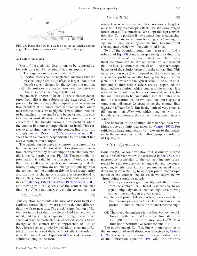
A. Contact line region
Most of the analytical descriptions to be reported be-low rely on a number of simplifying assumptions:
�i� The capillary number is small, Ca!0.1.�ii� Inertial effects can be neglected, meaning that the
viscous length scale ��=�2 /�� is larger than otherlength scales relevant for the contact line motion.
�iii� The surfaces are perfect �no heterogeneity�, sothere is no contact angle hysteresis.
Not much is known if �i� or �ii� are violated; depar-tures from �iii� is the subject of the next section. Weproceed by first solving the coupled interface-viscousflow problem at distances from the contact line wheremicroscopic effects are negligible. This solution then hasto be matched to the small-scale behavior near the con-tact line. Almost all of our analysis is going to be con-cerned with the two-dimensional flow problem wherethe contact line moves perpendicular to itself. This car-ries over to situations where the contact line is not toostrongly curved �Rio et al., 2005; Snoeijer et al., 2005�,such that the curvature perpendicular to the contact linealways remains much larger.
The calculation becomes much more transparent if welimit ourselves to the so-called lubrication approxima-tion, characterized by the assumption that the flow pro-file is nearly parabolic; see Fig. 25. The parabolic ap-proximation is valid in the presence of only a singlefluid, for small contact angles, and assuming that theforces driving the flow do not change too quickly. Nearthe contact line, the dominant driving force is capillarity,and the rate of change of curvature is proportional tothe capillary number �7�. Thus in a systematic expansionin Ca1/3 �Benney, 1966; Oron et al., 1997; Snoeijer, 2006�,and moving with the speed U of the contact line suchthat the profile is stationary, one obtains to leading order
3Ca/h2 = − h�. �49�
This equation represents a balance of viscous �left� andcapillary forces �right�, where a prime denotes differen-tiation with respect to x. The crucial simplification of Eq.�49� lies in the fact that the velocity field has been elimi-nated, and everything is expressed through the interfaceshape h�x� alone. Note that, as expected, viscous forcesdiverge as the contact line is approached �h→0�, sobody forces such as gravity which adds a constant to Eq.�49��, or any imposed shear, will not affect the solutionnear the contact line. Equation �49� is scale invariant,solutions being of the form
h�x� = LH�x/L� , �50�
where L is as yet unspecified. A characteristic length Lmust be set by microscopic effects like slip, long-rangedforces, or a diffuse interface. We adopt the sign conven-tion that Ca is positive if the contact line is advancing,which is the case we are now focusing on. Changing thesign in Eq. �49� �receding contact line� has importantconsequences, which will be elaborated later.
Two of the boundary conditions necessary to find asolution of Eq. �49� come from specifying the values of hand of the slope h� near the contact line. The missingthird condition can be derived from the requirementthat the local solution must match onto the macroscopicbehavior of the solution away from the contact line. Thisouter solution hout�x� will depend on the precise geom-etry of the problem and the forcing the liquid is sub-jected to. However, if the typical scale of the outer solu-tion and the microscopic scale L are well separated, theintermediate solution, which connects the contact linewith the outer solution, becomes universal, namely, forthe solution �50� to be compatible with the outer solu-tion, the curvatures of the two solutions must agree atsome small distance �x away from the contact line:hout� ��x�=H���x /L� /L. But in the limit of very small Lthis means that H����=0, which together with theboundary conditions at the contact line uniquely fixes asolution.
The behavior of the solution characterized by a van-ishing slope at infinity was given by Voinov �1976�. Forsufficiently large arguments x /L, relevant to the match-ing to the macroscopic problem, this asymptotic solutionof Eq. �49� is
h�3�x� = �m3 + 9Ca ln�x/L� . �51�
Equation �51�, or some variation of it, is usually referredto as the Cox-Voinov law. As discussed in Sec. I.C.2, themicroscopic properties of the contact line are repre-sented by a microscopic contact angle �m, and the corre-sponding length scale L. Both parameters need to bedetermined by matching to an appropriate microscopicmodel of the contact line, to which we return below.Three points should be noted:
�i� The slope varies logarithmically with the distancefrom the contact line. Thus it is impossible to as-sign a unique dynamical contact angle to a movingcontact line moving at a given speed.
�ii� The local profile �51� depends only very weakly onthe microscopic parameter L. It is much more im-portant to find estimates for the microscopic angle�m.
�iii� The speed dependence in the Cox-Voinov law fol-lows from the fact that Ca can be eliminated fromEq. �49� by the transformation h→Ca1/3h. It isthus not a perturbative result for small Ca.
The equivalent of Eq. �51�, but without resorting tothe assumption of small slopes, was also given by Voinov�1976�. The same result is found from a generalized formof the lubrication equation �49�, valid for arbitrary
� � � � � � � � � � � � � � � � � � � � � � � � � � �
� � � � � � � � � � � � � � � � � � � � � � � � � � �
� � � � � � � � � � � � � � � � � � � � � � � � � � �
� � � � � � � � � � � � � � � � � � � � � � � � � � �
z
h(x)
x
air
fluid
U
FIG. 25. Parabolic flow in a wedge near an advancing contactangle. The substrate moves with speed U to the right.
765Bonn et al.: Wetting and spreading
Rev. Mod. Phys., Vol. 81, No. 2, April–June 2009
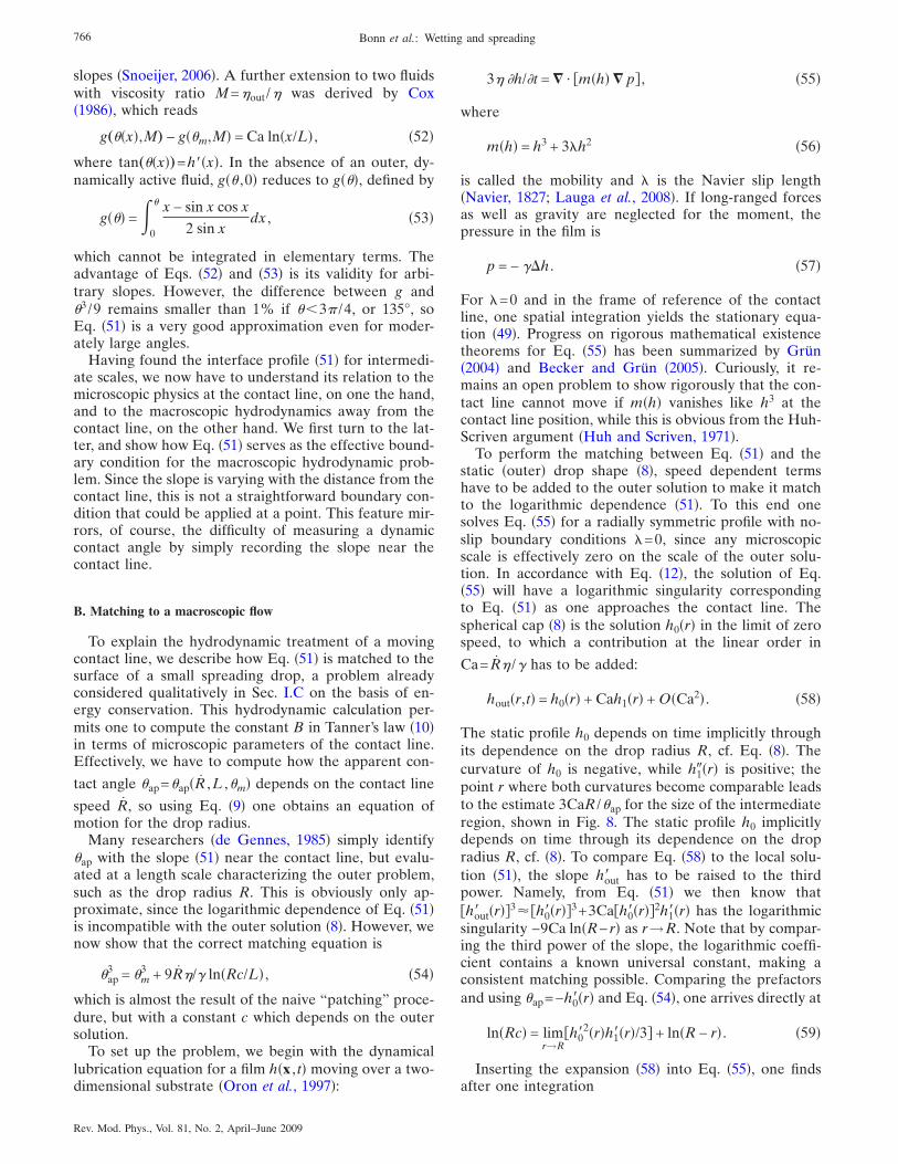
slopes �Snoeijer, 2006�. A further extension to two fluidswith viscosity ratio M=�out /� was derived by Cox�1986�, which reads
g„��x�,M… − g��m,M� = Ca ln�x/L� , �52�
where tan„��x�…=h��x�. In the absence of an outer, dy-namically active fluid, g�� ,0� reduces to g���, defined by
g��� = 0
� x − sin x cos x
2 sin xdx , �53�
which cannot be integrated in elementary terms. Theadvantage of Eqs. �52� and �53� is its validity for arbi-trary slopes. However, the difference between g and�3 /9 remains smaller than 1% if ��3 /4, or 135°, soEq. �51� is a very good approximation even for moder-ately large angles.
Having found the interface profile �51� for intermedi-ate scales, we now have to understand its relation to themicroscopic physics at the contact line, on one the hand,and to the macroscopic hydrodynamics away from thecontact line, on the other hand. We first turn to the lat-ter, and show how Eq. �51� serves as the effective bound-ary condition for the macroscopic hydrodynamic prob-lem. Since the slope is varying with the distance from thecontact line, this is not a straightforward boundary con-dition that could be applied at a point. This feature mir-rors, of course, the difficulty of measuring a dynamiccontact angle by simply recording the slope near thecontact line.
B. Matching to a macroscopic flow
To explain the hydrodynamic treatment of a movingcontact line, we describe how Eq. �51� is matched to thesurface of a small spreading drop, a problem alreadyconsidered qualitatively in Sec. I.C on the basis of en-ergy conservation. This hydrodynamic calculation per-mits one to compute the constant B in Tanner’s law �10�in terms of microscopic parameters of the contact line.Effectively, we have to compute how the apparent con-
tact angle �ap=�ap�R ,L ,�m� depends on the contact line
speed R, so using Eq. �9� one obtains an equation ofmotion for the drop radius.
Many researchers �de Gennes, 1985� simply identify�ap with the slope �51� near the contact line, but evalu-ated at a length scale characterizing the outer problem,such as the drop radius R. This is obviously only ap-proximate, since the logarithmic dependence of Eq. �51�is incompatible with the outer solution �8�. However, wenow show that the correct matching equation is
�ap3 = �m
3 + 9R�/� ln�Rc/L� , �54�
which is almost the result of the naive “patching” proce-dure, but with a constant c which depends on the outersolution.
To set up the problem, we begin with the dynamicallubrication equation for a film h�x , t� moving over a two-dimensional substrate �Oron et al., 1997�:
3� �h/�t = � · m�h� � p� , �55�
where
m�h� = h3 + 3"h2 �56�
is called the mobility and " is the Navier slip length�Navier, 1827; Lauga et al., 2008�. If long-ranged forcesas well as gravity are neglected for the moment, thepressure in the film is
p = − ��h . �57�
For "=0 and in the frame of reference of the contactline, one spatial integration yields the stationary equa-tion �49�. Progress on rigorous mathematical existencetheorems for Eq. �55� has been summarized by Grün�2004� and Becker and Grün �2005�. Curiously, it re-mains an open problem to show rigorously that the con-tact line cannot move if m�h� vanishes like h3 at thecontact line position, while this is obvious from the Huh-Scriven argument �Huh and Scriven, 1971�.
To perform the matching between Eq. �51� and thestatic �outer� drop shape �8�, speed dependent termshave to be added to the outer solution to make it matchto the logarithmic dependence �51�. To this end onesolves Eq. �55� for a radially symmetric profile with no-slip boundary conditions "=0, since any microscopicscale is effectively zero on the scale of the outer solu-tion. In accordance with Eq. �12�, the solution of Eq.�55� will have a logarithmic singularity correspondingto Eq. �51� as one approaches the contact line. Thespherical cap �8� is the solution h0�r� in the limit of zerospeed, to which a contribution at the linear order in
Ca= R� /� has to be added:
hout�r,t� = h0�r� + Cah1�r� + O�Ca2� . �58�
The static profile h0 depends on time implicitly throughits dependence on the drop radius R, cf. Eq. �8�. Thecurvature of h0 is negative, while h1��r� is positive; thepoint r where both curvatures become comparable leadsto the estimate 3CaR /�ap for the size of the intermediateregion, shown in Fig. 8. The static profile h0 implicitlydepends on time through its dependence on the dropradius R, cf. �8�. To compare Eq. �58� to the local solu-tion �51�, the slope hout� has to be raised to the thirdpower. Namely, from Eq. �51� we then know thathout� �r��3�h0��r��3+3Cah0��r��2h1��r� has the logarithmicsingularity −9Ca ln�R−r� as r→R. Note that by compar-ing the third power of the slope, the logarithmic coeffi-cient contains a known universal constant, making aconsistent matching possible. Comparing the prefactorsand using �ap=−h0��r� and Eq. �54�, one arrives directly at
ln�Rc� = limr→R
h0�2�r�h1��r�/3� + ln�R − r� . �59�
Inserting the expansion �58� into Eq. �55�, one findsafter one integration
766 Bonn et al.: Wetting and spreading
Rev. Mod. Phys., Vol. 81, No. 2, April–June 2009
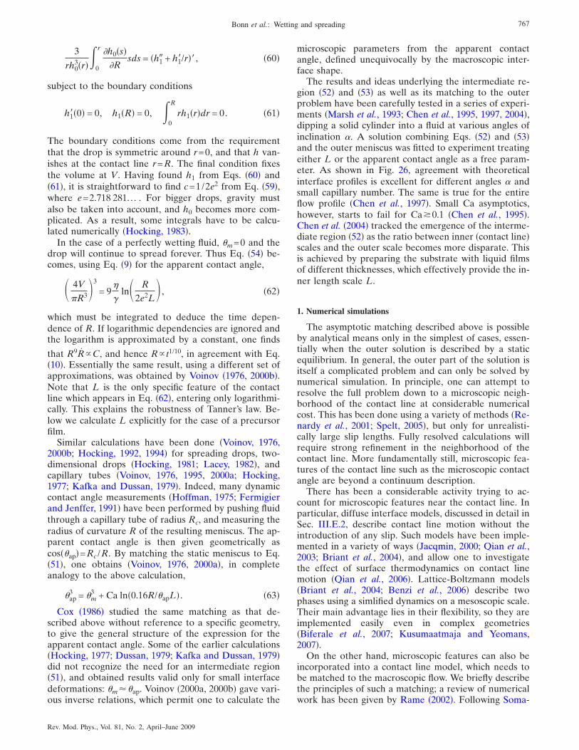
3
rh03�r� 0
r �h0�s��R
sds = �h1� + h1�/r��, �60�
subject to the boundary conditions
h1��0� = 0, h1�R� = 0, 0
R
rh1�r�dr = 0. �61�
The boundary conditions come from the requirementthat the drop is symmetric around r=0, and that h van-ishes at the contact line r=R. The final condition fixesthe volume at V. Having found h1 from Eqs. �60� and�61�, it is straightforward to find c=1/2e2 from Eq. �59�,where e=2.718 281. . . . For bigger drops, gravity mustalso be taken into account, and h0 becomes more com-plicated. As a result, some integrals have to be calcu-lated numerically �Hocking, 1983�.
In the case of a perfectly wetting fluid, �m=0 and thedrop will continue to spread forever. Thus Eq. �54� be-comes, using Eq. �9� for the apparent contact angle,
� 4V
R3�3
= 9�
�ln� R
2e2L� , �62�
which must be integrated to deduce the time depen-dence of R. If logarithmic dependencies are ignored andthe logarithm is approximated by a constant, one finds
that R9RC, and hence R t1/10, in agreement with Eq.�10�. Essentially the same result, using a different set ofapproximations, was obtained by Voinov �1976, 2000b�.Note that L is the only specific feature of the contactline which appears in Eq. �62�, entering only logarithmi-cally. This explains the robustness of Tanner’s law. Be-low we calculate L explicitly for the case of a precursorfilm.
Similar calculations have been done �Voinov, 1976,2000b; Hocking, 1992, 1994� for spreading drops, two-dimensional drops �Hocking, 1981; Lacey, 1982�, andcapillary tubes �Voinov, 1976, 1995, 2000a; Hocking,1977; Kafka and Dussan, 1979�. Indeed, many dynamiccontact angle measurements �Hoffman, 1975; Fermigierand Jenffer, 1991� have been performed by pushing fluidthrough a capillary tube of radius Rc, and measuring theradius of curvature R of the resulting meniscus. The ap-parent contact angle is then given geometrically ascos��ap�=Rc /R. By matching the static meniscus to Eq.�51�, one obtains �Voinov, 1976, 2000a�, in completeanalogy to the above calculation,
�ap3 = �m
3 + Ca ln�0.16R/�apL� . �63�
Cox �1986� studied the same matching as that de-scribed above without reference to a specific geometry,to give the general structure of the expression for theapparent contact angle. Some of the earlier calculations�Hocking, 1977; Dussan, 1979; Kafka and Dussan, 1979�did not recognize the need for an intermediate region�51�, and obtained results valid only for small interfacedeformations: �m��ap. Voinov �2000a, 2000b� gave vari-ous inverse relations, which permit one to calculate the
microscopic parameters from the apparent contactangle, defined unequivocally by the macroscopic inter-face shape.
The results and ideas underlying the intermediate re-gion �52� and �53� as well as its matching to the outerproblem have been carefully tested in a series of experi-ments �Marsh et al., 1993; Chen et al., 1995, 1997, 2004�,dipping a solid cylinder into a fluid at various angles ofinclination �. A solution combining Eqs. �52� and �53�and the outer meniscus was fitted to experiment treatingeither L or the apparent contact angle as a free param-eter. As shown in Fig. 26, agreement with theoreticalinterface profiles is excellent for different angles � andsmall capillary number. The same is true for the entireflow profile �Chen et al., 1997�. Small Ca asymptotics,however, starts to fail for Ca�0.1 �Chen et al., 1995�.Chen et al. �2004� tracked the emergence of the interme-diate region �52� as the ratio between inner �contact line�scales and the outer scale becomes more disparate. Thisis achieved by preparing the substrate with liquid filmsof different thicknesses, which effectively provide the in-ner length scale L.
1. Numerical simulations
The asymptotic matching described above is possibleby analytical means only in the simplest of cases, essen-tially when the outer solution is described by a staticequilibrium. In general, the outer part of the solution isitself a complicated problem and can only be solved bynumerical simulation. In principle, one can attempt toresolve the full problem down to a microscopic neigh-borhood of the contact line at considerable numericalcost. This has been done using a variety of methods �Re-nardy et al., 2001; Spelt, 2005�, but only for unrealisti-cally large slip lengths. Fully resolved calculations willrequire strong refinement in the neighborhood of thecontact line. More fundamentally still, microscopic fea-tures of the contact line such as the microscopic contactangle are beyond a continuum description.
There has been a considerable activity trying to ac-count for microscopic features near the contact line. Inparticular, diffuse interface models, discussed in detail inSec. III.E.2, describe contact line motion without theintroduction of any slip. Such models have been imple-mented in a variety of ways �Jacqmin, 2000; Qian et al.,2003; Briant et al., 2004�, and allow one to investigatethe effect of surface thermodynamics on contact linemotion �Qian et al., 2006�. Lattice-Boltzmann models�Briant et al., 2004; Benzi et al., 2006� describe twophases using a simlified dynamics on a mesoscopic scale.Their main advantage lies in their flexibility, so they areimplemented easily even in complex geometries�Biferale et al., 2007; Kusumaatmaja and Yeomans,2007�.
On the other hand, microscopic features can also beincorporated into a contact line model, which needs tobe matched to the macroscopic flow. We briefly describethe principles of such a matching; a review of numericalwork has been given by Rame �2002�. Following Soma-
767Bonn et al.: Wetting and spreading
Rev. Mod. Phys., Vol. 81, No. 2, April–June 2009
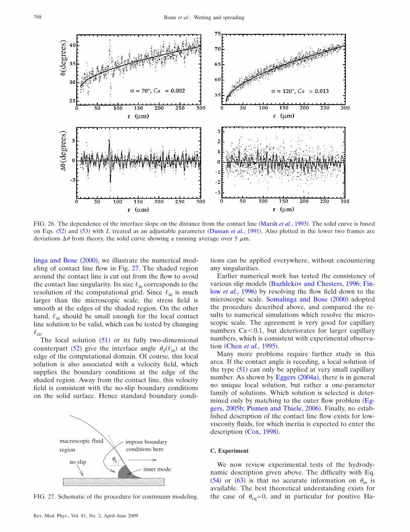
linga and Bose �2000�, we illustrate the numerical mod-eling of contact line flow in Fig. 27. The shaded regionaround the contact line is cut out from the flow to avoidthe contact line singularity. Its size �in corresponds to theresolution of the computational grid. Since �in is muchlarger than the microscopic scale, the stress field issmooth at the edges of the shaded region. On the otherhand, �in should be small enough for the local contactline solution to be valid, which can be tested by changing�in.
The local solution �51� or its fully two-dimensionalcounterpart �52� give the interface angle �d��in� at theedge of the computational domain. Of course, this localsolution is also associated with a velocity field, whichsupplies the boundary conditions at the edge of theshaded region. Away from the contact line, this velocityfield is consistent with the no-slip boundary conditionson the solid surface. Hence standard boundary condi-
tions can be applied everywhere, without encounteringany singularities.
Earlier numerical work has tested the consistency ofvarious slip models �Bazhlekov and Chesters, 1996; Fin-low et al., 1996� by resolving the flow field down to themicroscopic scale. Somalinga and Bose �2000� adoptedthe procedure described above, and compared the re-sults to numerical simulations which resolve the micro-scopic scale. The agreement is very good for capillarynumbers Ca�0.1, but deteriorates for larger capillarynumbers, which is consistent with experimental observa-tion �Chen et al., 1995�.
Many more problems require further study in thisarea. If the contact angle is receding, a local solution ofthe type �51� can only be applied at very small capillarynumber. As shown by Eggers �2004a�, there is in generalno unique local solution, but rather a one-parameterfamily of solutions. Which solution is selected is deter-mined only by matching to the outer flow problem �Eg-gers, 2005b; Pismen and Thiele, 2006�. Finally, no estab-lished description of the contact line flow exists for low-viscosity fluids, for which inertia is expected to enter thedescription �Cox, 1998�.
C. Experiment
We now review experimental tests of the hydrody-namic description given above. The difficulty with Eq.�54� or �63� is that no accurate information on �m isavailable. The best theoretical understanding exists forthe case of �eq=0, and in particular for positive Ha-
FIG. 26. The dependence of the interface slope on the distance from the contact line �Marsh et al., 1993�. The solid curve is basedon Eqs. �52� and �53� with L treated as an adjustable parameter �Dussan et al., 1991�. Also plotted in the lower two frames aredeviations �� from theory, the solid curve showing a running average over 5 �m.
� � � � � � � � � � � � � � � � � � � � �
� � � � � � � � � � � � � � � � � � � � �
� � � � � � � � � � � � � � � � � � � � �
� � � � � � � � � � � � � � � � � � � � �
no slip θd
macroscopic fluid
region
inner model
impose boundaryconditions here
FIG. 27. Schematic of the procedure for continuum modeling.
768 Bonn et al.: Wetting and spreading
Rev. Mod. Phys., Vol. 81, No. 2, April–June 2009
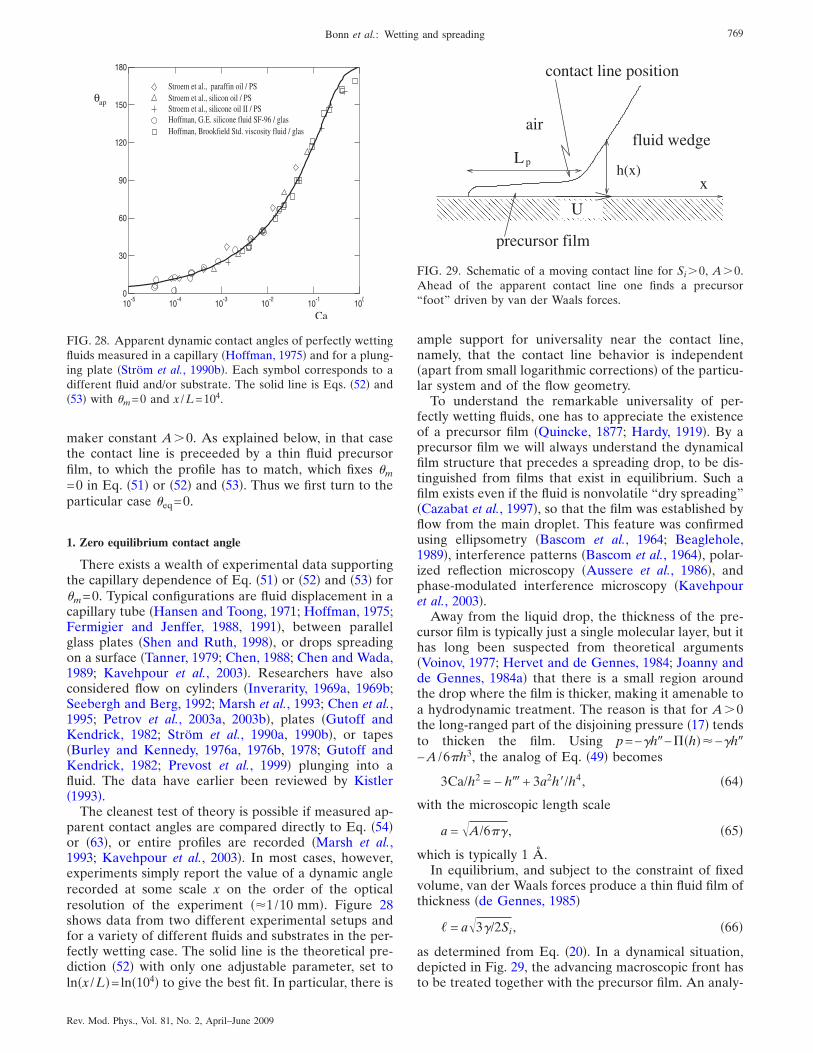
maker constant A�0. As explained below, in that casethe contact line is preceeded by a thin fluid precursorfilm, to which the profile has to match, which fixes �m=0 in Eq. �51� or �52� and �53�. Thus we first turn to theparticular case �eq=0.
1. Zero equilibrium contact angle
There exists a wealth of experimental data supportingthe capillary dependence of Eq. �51� or �52� and �53� for�m=0. Typical configurations are fluid displacement in acapillary tube �Hansen and Toong, 1971; Hoffman, 1975;Fermigier and Jenffer, 1988, 1991�, between parallelglass plates �Shen and Ruth, 1998�, or drops spreadingon a surface �Tanner, 1979; Chen, 1988; Chen and Wada,1989; Kavehpour et al., 2003�. Researchers have alsoconsidered flow on cylinders �Inverarity, 1969a, 1969b;Seebergh and Berg, 1992; Marsh et al., 1993; Chen et al.,1995; Petrov et al., 2003a, 2003b�, plates �Gutoff andKendrick, 1982; Ström et al., 1990a, 1990b�, or tapes�Burley and Kennedy, 1976a, 1976b, 1978; Gutoff andKendrick, 1982; Prevost et al., 1999� plunging into afluid. The data have earlier been reviewed by Kistler�1993�.
The cleanest test of theory is possible if measured ap-parent contact angles are compared directly to Eq. �54�or �63�, or entire profiles are recorded �Marsh et al.,1993; Kavehpour et al., 2003�. In most cases, however,experiments simply report the value of a dynamic anglerecorded at some scale x on the order of the opticalresolution of the experiment ��1/10 mm�. Figure 28shows data from two different experimental setups andfor a variety of different fluids and substrates in the per-fectly wetting case. The solid line is the theoretical pre-diction �52� with only one adjustable parameter, set toln�x /L�=ln�104� to give the best fit. In particular, there is
ample support for universality near the contact line,namely, that the contact line behavior is independent�apart from small logarithmic corrections� of the particu-lar system and of the flow geometry.
To understand the remarkable universality of per-fectly wetting fluids, one has to appreciate the existenceof a precursor film �Quincke, 1877; Hardy, 1919�. By aprecursor film we will always understand the dynamicalfilm structure that precedes a spreading drop, to be dis-tinguished from films that exist in equilibrium. Such afilm exists even if the fluid is nonvolatile “dry spreading”�Cazabat et al., 1997�, so that the film was established byflow from the main droplet. This feature was confirmedusing ellipsometry �Bascom et al., 1964; Beaglehole,1989�, interference patterns �Bascom et al., 1964�, polar-ized reflection microscopy �Aussere et al., 1986�, andphase-modulated interference microscopy �Kavehpouret al., 2003�.
Away from the liquid drop, the thickness of the pre-cursor film is typically just a single molecular layer, but ithas long been suspected from theoretical arguments�Voinov, 1977; Hervet and de Gennes, 1984; Joanny andde Gennes, 1984a� that there is a small region aroundthe drop where the film is thicker, making it amenable toa hydrodynamic treatment. The reason is that for A�0the long-ranged part of the disjoining pressure �17� tendsto thicken the film. Using p=−�h�−��h��−�h�−A /6h3, the analog of Eq. �49� becomes
3Ca/h2 = − h� + 3a2h�/h4, �64�
with the microscopic length scale
a = �A/6� , �65�
which is typically 1 Å.In equilibrium, and subject to the constraint of fixed
volume, van der Waals forces produce a thin fluid film ofthickness �de Gennes, 1985�
� = a�3�/2Si, �66�
as determined from Eq. �20�. In a dynamical situation,depicted in Fig. 29, the advancing macroscopic front hasto be treated together with the precursor film. An analy-
Ca
θap
10-5
10-4
10-3
10-2
10-1
100
0
30
60
90
120
150
180
Stroem et al., paraffin oil / PSStroem et al., silicon oil / PSStroem et al., silicone oil II / PSHoffman, G.E. silicone fluid SF-96 / glasHoffman, Brookfield Std. viscosity fluid / glas
FIG. 28. Apparent dynamic contact angles of perfectly wettingfluids measured in a capillary �Hoffman, 1975� and for a plung-ing plate �Ström et al., 1990b�. Each symbol corresponds to adifferent fluid and/or substrate. The solid line is Eqs. �52� and�53� with �m=0 and x /L=104.
� � � � � � � � � � � � � � � � � � � � � � � � � � � �
� � � � � � � � � � � � � � � � � � � � � � � � � � � �
L p
contact line position
precursor film
xh(x)
airfluid wedge
U
FIG. 29. Schematic of a moving contact line for Si�0, A�0.Ahead of the apparent contact line one finds a precursor“foot” driven by van der Waals forces.
769Bonn et al.: Wetting and spreading
Rev. Mod. Phys., Vol. 81, No. 2, April–June 2009
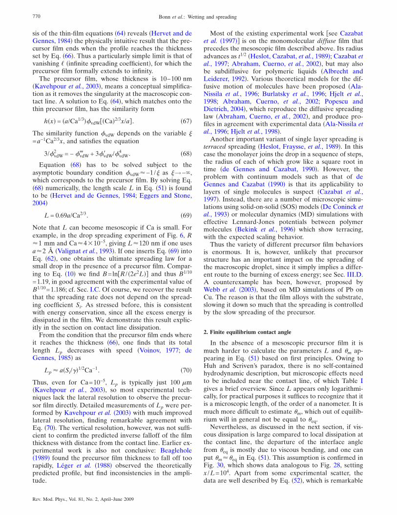
sis of the thin-film equations �64� reveals �Hervet and deGennes, 1984� the physically intuitive result that the pre-cursor film ends when the profile reaches the thicknessset by Eq. �66�. Thus a particularly simple limit is that ofvanishing � �infinite spreading coefficient�, for which theprecursor film formally extends to infinity.
The precursor film, whose thickness is 10–100 nm�Kavehpour et al., 2003�, means a conceptual simplifica-tion as it removes the singularity at the macroscopic con-tact line. A solution to Eq. �64�, which matches onto thethin precursor film, has the similarity form
h�x� = �a/Ca1/3�#vdW�Ca�2/3x/a� . �67�
The similarity function #vdW depends on the variable �=a−1Ca2/3x, and satisfies the equation
3/#vdW2 = − #vdW� + 3#vdW� /#vdW
4 . �68�
Equation �68� has to be solved subject to theasymptotic boundary condition #vdW�−1/� as �→−�,which corresponds to the precursor film. By solving Eq.�68� numerically, the length scale L in Eq. �51� is foundto be �Hervet and de Gennes, 1984; Eggers and Stone,2004�
L = 0.69a/Ca2/3. �69�
Note that L can become mesoscopic if Ca is small. Forexample, in the drop spreading experiment of Fig. 6, R�1 mm and Ca�4�10−5, giving L�120 nm if one usesa�2 Å �Valignat et al., 1993�. If one inserts Eq. �69� intoEq. �62�, one obtains the ultimate spreading law for asmall drop in the presence of a precursor film. Compar-ing to Eq. �10� we find B=lnR / �2e2L�� and thus B1/10
=1.19, in good agreement with the experimental value ofB1/10=1.186; cf. Sec. I.C. Of course, we recover the resultthat the spreading rate does not depend on the spread-ing coefficient Si. As stressed before, this is consistentwith energy conservation, since all the excess energy isdissipated in the film. We demonstrate this result explic-itly in the section on contact line dissipation.
From the condition that the precursor film ends whereit reaches the thickness �66�, one finds that its totallength Lp decreases with speed �Voinov, 1977; deGennes, 1985� as
Lp � a�Si/��1/2Ca−1. �70�
Thus, even for Ca=10−5, Lp is typically just 100 �m�Kavehpour et al., 2003�, so most experimental tech-niques lack the lateral resolution to observe the precur-sor film directly. Detailed measurements of Lp were per-formed by Kavehpour et al. �2003� with much improvedlateral resolution, finding remarkable agreement withEq. �70�. The vertical resolution, however, was not suffi-cient to confirm the predicted inverse falloff of the filmthickness with distance from the contact line. Earlier ex-perimental work is also not conclusive: Beaglehole�1989� found the precursor film thickness to fall off toorapidly, Léger et al. �1988� observed the theoreticallypredicted profile, but find inconsistencies in the ampli-tude.
Most of the existing experimental work see Cazabatet al. �1997�� is on the monomolecular diffuse film thatprecedes the mesoscopic film described above. Its radiusadvances as t1/2 �Heslot, Cazabat, et al., 1989�; Cazabat etal., 1997; Abraham, Cuerno, et al., 2002�, but may alsobe subdiffusive for polymeric liquids �Albrecht andLeiderer, 1992�. Various theoretical models for the dif-fusive motion of molecules have been proposed �Ala-Nissila et al., 1996; Burlatsky et al., 1996; Hjelt et al.,1998; Abraham, Cuerno, et al., 2002; Popescu andDietrich, 2004�, which reproduce the diffusive spreadinglaw �Abraham, Cuerno, et al., 2002�, and produce pro-files in agreement with experimental data �Ala-Nissila etal., 1996; Hjelt et al., 1998�.
Another important variant of single layer spreading isterraced spreading �Heslot, Fraysse, et al., 1989�. In thiscase the monolayer joins the drop in a sequence of steps,the radius of each of which grow like a square root intime �de Gennes and Cazabat, 1990�. However, theproblem with continuum models such as that of deGennes and Cazabat �1990� is that its applicability tolayers of single molecules is suspect �Cazabat et al.,1997�. Instead, there are a number of microscopic simu-lations using solid-on-solid �SOS� models �De Coninck etal., 1993� or molecular dynamics �MD� simulations witheffective Lennard-Jones potentials between polymermolecules �Bekink et al., 1996� which show terracing,with the expected scaling behavior.
Thus the variety of different precursor film behaviorsis enormous. It is, however, unlikely that precursorstructure has an important impact on the spreading ofthe macroscopic droplet, since it simply implies a differ-ent route to the burning of excess energy; see Sec. III.D.A counterexample has been, however, proposed byWebb et al. �2003�, based on MD simulations of Pb onCu. The reason is that the film alloys with the substrate,slowing it down so much that the spreading is controlledby the slow spreading of the precursor.
2. Finite equilibrium contact angle
In the absence of a mesoscopic precursor film it ismuch harder to calculate the parameters L and �m ap-pearing in Eq. �51� based on first principles. Owing toHuh and Scriven’s paradox, there is no self-containedhydrodynamic description, but microscopic effects needto be included near the contact line, of which Table Igives a brief overview. Since L appears only logarithmi-cally, for practical purposes it suffices to recognize that itis a microscopic length, of the order of a nanometer. It ismuch more difficult to estimate �m, which out of equilib-rium will in general not be equal to �eq.
Nevertheless, as discussed in the next section, if vis-cous dissipation is large compared to local dissipation atthe contact line, the departure of the interface anglefrom �eq is mostly due to viscous bending, and one canput �m��eq in Eq. �51�. This assumption is confirmed inFig. 30, which shows data analogous to Fig. 28, settingx /L=104. Apart from some experimental scatter, thedata are well described by Eq. �52�, which is remarkable
770 Bonn et al.: Wetting and spreading
Rev. Mod. Phys., Vol. 81, No. 2, April–June 2009
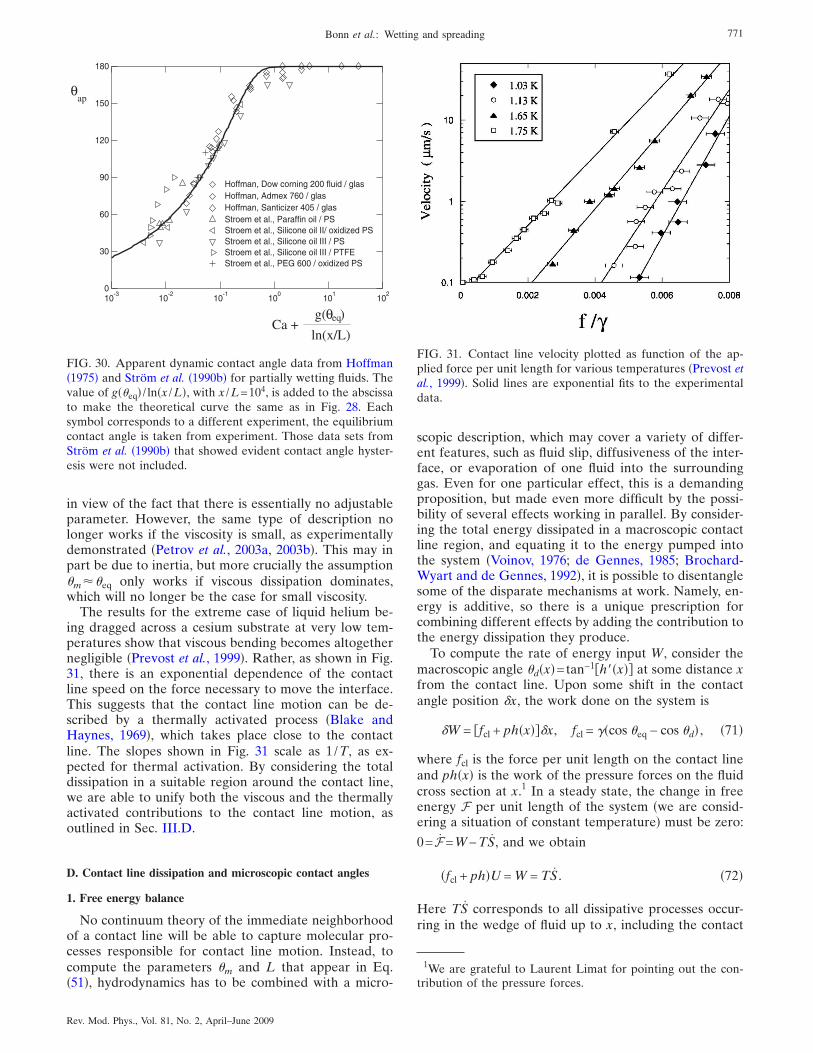
in view of the fact that there is essentially no adjustableparameter. However, the same type of description nolonger works if the viscosity is small, as experimentallydemonstrated �Petrov et al., 2003a, 2003b�. This may inpart be due to inertia, but more crucially the assumption�m��eq only works if viscous dissipation dominates,which will no longer be the case for small viscosity.
The results for the extreme case of liquid helium be-ing dragged across a cesium substrate at very low tem-peratures show that viscous bending becomes altogethernegligible �Prevost et al., 1999�. Rather, as shown in Fig.31, there is an exponential dependence of the contactline speed on the force necessary to move the interface.This suggests that the contact line motion can be de-scribed by a thermally activated process �Blake andHaynes, 1969�, which takes place close to the contactline. The slopes shown in Fig. 31 scale as 1/T, as ex-pected for thermal activation. By considering the totaldissipation in a suitable region around the contact line,we are able to unify both the viscous and the thermallyactivated contributions to the contact line motion, asoutlined in Sec. III.D.
D. Contact line dissipation and microscopic contact angles
1. Free energy balance
No continuum theory of the immediate neighborhoodof a contact line will be able to capture molecular pro-cesses responsible for contact line motion. Instead, tocompute the parameters �m and L that appear in Eq.�51�, hydrodynamics has to be combined with a micro-
scopic description, which may cover a variety of differ-ent features, such as fluid slip, diffusiveness of the inter-face, or evaporation of one fluid into the surroundinggas. Even for one particular effect, this is a demandingproposition, but made even more difficult by the possi-bility of several effects working in parallel. By consider-ing the total energy dissipated in a macroscopic contactline region, and equating it to the energy pumped intothe system �Voinov, 1976; de Gennes, 1985; Brochard-Wyart and de Gennes, 1992�, it is possible to disentanglesome of the disparate mechanisms at work. Namely, en-ergy is additive, so there is a unique prescription forcombining different effects by adding the contribution tothe energy dissipation they produce.
To compute the rate of energy input W, consider themacroscopic angle �d�x�=tan−1h��x�� at some distance xfrom the contact line. Upon some shift in the contactangle position $x, the work done on the system is
$W = fcl + ph�x��$x, fcl = ��cos �eq − cos �d� , �71�
where fcl is the force per unit length on the contact lineand ph�x� is the work of the pressure forces on the fluidcross section at x.1 In a steady state, the change in freeenergy F per unit length of the system �we are consid-ering a situation of constant temperature� must be zero:
0= F=W−TS, and we obtain
�fcl + ph�U = W = TS . �72�
Here TS corresponds to all dissipative processes occur-ring in the wedge of fluid up to x, including the contact
1We are grateful to Laurent Limat for pointing out the con-tribution of the pressure forces.
10-3
10-2
10-1
100
101
102
0
30
60
90
120
150
180
Hoffman, Dow corning 200 fluid / glasHoffman, Admex 760 / glasHoffman, Santicizer 405 / glasStroem et al., Paraffin oil / PSStroem et al., Silicone oil II/ oxidized PSStroem et al., Silicone oil III / PSStroem et al., Silicone oil III / PTFEStroem et al., PEG 600 / oxidized PS
θeq
θ
Ca +ln(x/L)
g( )
ap
FIG. 30. Apparent dynamic contact angle data from Hoffman�1975� and Ström et al. �1990b� for partially wetting fluids. Thevalue of g��eq� / ln�x /L�, with x /L=104, is added to the abscissato make the theoretical curve the same as in Fig. 28. Eachsymbol corresponds to a different experiment, the equilibriumcontact angle is taken from experiment. Those data sets fromStröm et al. �1990b� that showed evident contact angle hyster-esis were not included.
FIG. 31. Contact line velocity plotted as function of the ap-plied force per unit length for various temperatures �Prevost etal., 1999�. Solid lines are exponential fits to the experimentaldata.
771Bonn et al.: Wetting and spreading
Rev. Mod. Phys., Vol. 81, No. 2, April–June 2009
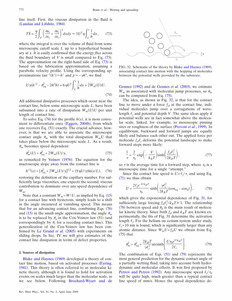
line itself. First, the viscous dissipation in the fluid is�Landau and Lifshitz, 1984�
TS =�
2
V� �ui
�xj+
�uj
�xi�2
dxdy � 3U2� L
x 1
hdx , �73�
where the integral is over the volume of fluid from somemicroscopic cutoff scale L up to a hypothetical bound-ary at x. It is easily confirmed that the energy flux acrossthe fluid boundary of V is small compared to Eq. �73�.The approximation on the right-hand side of Eq. �73� isbased on the lubrication approximation, assuming aparabolic velocity profile. Using the corresponding ap-proximations tan−1�h���h� and p�−�h�, we find
U��h�2 − �eq2 − 2h�h� = 6�U2
L
x 1
hdx + 2Wm�U�U .
�74�
All additional dissipative processes which occur near thecontact line, below some microscopic scale L, have beensubsumed into a rate of dissipation Wm�U�U per unitlength of contact line.
To solve Eq. �74� for the profile h�x�, it is most conve-nient to differentiate once �Eggers, 2004b�, from whichone recovers Eq. �51� exactly. The crucial advance, how-ever, is that we are able to associate the microscopiccontact angle �m with the total dissipation WmU thattakes place below the microscopic scale L. As a result,�m becomes speed dependent:
�m2 �U� = �eq
2 + 2Wm�U�/� , �75�
as remarked by Voinov �1976�. The equation for themacroscopic slope away from the contact line is
h�3�x� = �eq2 + 2Wm�U�/��3/2 + �9�U/��ln�x/L� , �76�
restoring the definition of the capillary number. For suf-ficiently large viscosities, one expects the second, viscouscontribution to dominate over any speed dependence ofWm.
Note that a constant Wm=W /U, as implied by Eq. �15�for a contact line with hysteresis, simply leads to a shiftin the angle measured at vanishing speed. This meansthat for an advancing contact line, combining Eqs. �76�and �15� in the small-angle approximation, the angle �mis to be replaced by �a in the Cox-Voinov law �51� �andcorrespondingly by �r for a receding contact line�. Thisgeneralization of the Cox-Voinov law has been con-firmed by Le Grand et al. �2005� with experiments onsliding drops. In Sec. IV we will give estimates of thecontact line dissipation in terms of defect properties.
2. Sources of dissipation
Blake and Haynes �1969� developed a theory of con-tact line motion, based on activated processes �Eyring,1941�. This theory is often referred to as molecular ki-netic theory, although it is found to hold for activationevents on scales much larger than the molecular scale, aswe see below. Following Brochard-Wyart and de
Gennes �1992� and de Gennes et al. �2003�, we estimateWm as associated with molecular jump processes, so �mcan be computed from Eq. �75�.
The idea, as shown in Fig. 32, is that for the contactline to move under a force fcl at the contact line, indi-vidual molecules jump over a corrugations of wave-length �j and potential depth V. The same ideas apply ifpotential wells are in fact somewhat above the molecu-lar scale, linked, for example, to mesoscopic pinningsites or roughness of the surface �Prevost et al., 1999�. Inequilibrium, backward and forward jumps are equallylikely and balance each other out. The applied force permolecule fcl�j deforms the potential landscape to makeforward steps more likely:
1
�=
2
�0exp�−
V
kBT�sinh� fcl�j
2
2kBT� , �77�
so � is the average time for a forward step, where �0 is amicroscopic time for a single “attempt.”
Since the contact line speed is U=�j /�, and using Eq.�71� we thus obtain
U =2�je
−V/kBT
�0sinh� ��j
2
2kBT�coseq − cosd�� , �78�
which gives the exponential dependence of Fig. 31, forsufficiently large forcing fcl�j
2 /kBT%1. The relationship�78� between speed and �d is the main result of molecu-lar kinetic theory. Since both fcl and kBT are known ex-perimentally, the fits of Fig. 31 determine the activationlength �j. For the helium on cesium system under study,�j=10 nm is found, which is significantly larger than anyatomic distance. Since WmU= fclU we obtain from Eq.�75� that
�m2 = �eq
2 +2kBT
��j2 arcsinh�U�0eV/kBT
2�j . �79�
The combination of Eqs. �51� and �79� represents themost general prediction for the dynamic contact angle ofa partially wetting fluid, taking into account both hydro-dynamic and molecular effects. It was first proposed byPetrov and Petrov �1992�. Any microscopic speed �j /�0will be quite high, much greater than a typical contactline speed of mm/s. Hence the speed dependence de-
V
l
f
j
cl
FIG. 32. Schematic of the theory by Blake and Haynes �1969�,associating contact line motion with the hopping of moleculesbetween the potential wells provided by the substrate.
772 Bonn et al.: Wetting and spreading
Rev. Mod. Phys., Vol. 81, No. 2, April–June 2009
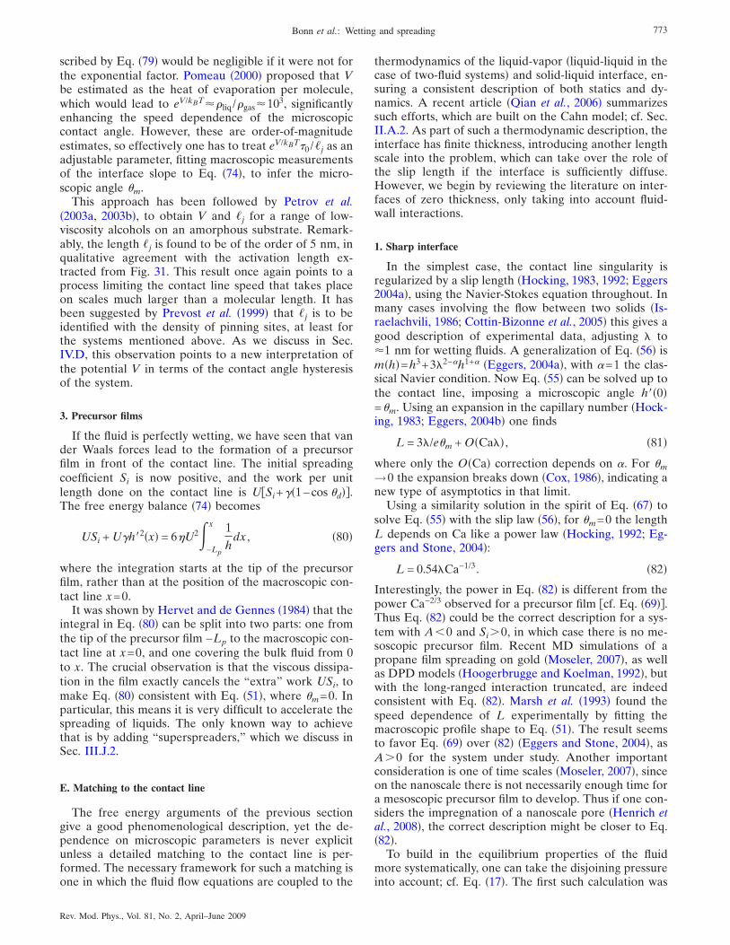
scribed by Eq. �79� would be negligible if it were not forthe exponential factor. Pomeau �2000� proposed that Vbe estimated as the heat of evaporation per molecule,which would lead to eV/kBT��liq /�gas�103, significantlyenhancing the speed dependence of the microscopiccontact angle. However, these are order-of-magnitudeestimates, so effectively one has to treat eV/kBT�0 /�j as anadjustable parameter, fitting macroscopic measurementsof the interface slope to Eq. �74�, to infer the micro-scopic angle �m.
This approach has been followed by Petrov et al.�2003a, 2003b�, to obtain V and �j for a range of low-viscosity alcohols on an amorphous substrate. Remark-ably, the length �j is found to be of the order of 5 nm, inqualitative agreement with the activation length ex-tracted from Fig. 31. This result once again points to aprocess limiting the contact line speed that takes placeon scales much larger than a molecular length. It hasbeen suggested by Prevost et al. �1999� that �j is to beidentified with the density of pinning sites, at least forthe systems mentioned above. As we discuss in Sec.IV.D, this observation points to a new interpretation ofthe potential V in terms of the contact angle hysteresisof the system.
3. Precursor films
If the fluid is perfectly wetting, we have seen that vander Waals forces lead to the formation of a precursorfilm in front of the contact line. The initial spreadingcoefficient Si is now positive, and the work per unitlength done on the contact line is USi+��1−cos �d��.The free energy balance �74� becomes
USi + U�h�2�x� = 6�U2 −Lp
x 1
hdx , �80�
where the integration starts at the tip of the precursorfilm, rather than at the position of the macroscopic con-tact line x=0.
It was shown by Hervet and de Gennes �1984� that theintegral in Eq. �80� can be split into two parts: one fromthe tip of the precursor film −Lp to the macroscopic con-tact line at x=0, and one covering the bulk fluid from 0to x. The crucial observation is that the viscous dissipa-tion in the film exactly cancels the “extra” work USi, tomake Eq. �80� consistent with Eq. �51�, where �m=0. Inparticular, this means it is very difficult to accelerate thespreading of liquids. The only known way to achievethat is by adding “superspreaders,” which we discuss inSec. III.J.2.
E. Matching to the contact line
The free energy arguments of the previous sectiongive a good phenomenological description, yet the de-pendence on microscopic parameters is never explicitunless a detailed matching to the contact line is per-formed. The necessary framework for such a matching isone in which the fluid flow equations are coupled to the
thermodynamics of the liquid-vapor �liquid-liquid in thecase of two-fluid systems� and solid-liquid interface, en-suring a consistent description of both statics and dy-namics. A recent article �Qian et al., 2006� summarizessuch efforts, which are built on the Cahn model; cf. Sec.II.A.2. As part of such a thermodynamic description, theinterface has finite thickness, introducing another lengthscale into the problem, which can take over the role ofthe slip length if the interface is sufficiently diffuse.However, we begin by reviewing the literature on inter-faces of zero thickness, only taking into account fluid-wall interactions.
1. Sharp interface
In the simplest case, the contact line singularity isregularized by a slip length �Hocking, 1983, 1992; Eggers2004a�, using the Navier-Stokes equation throughout. Inmany cases involving the flow between two solids �Is-raelachvili, 1986; Cottin-Bizonne et al., 2005� this gives agood description of experimental data, adjusting " to�1 nm for wetting fluids. A generalization of Eq. �56� ism�h�=h3+3"2−�h1+� �Eggers, 2004a�, with �=1 the clas-sical Navier condition. Now Eq. �55� can be solved up tothe contact line, imposing a microscopic angle h��0�=�m. Using an expansion in the capillary number �Hock-ing, 1983; Eggers, 2004b� one finds
L = 3"/e�m + O�Ca"� , �81�
where only the O�Ca� correction depends on �. For �m→0 the expansion breaks down �Cox, 1986�, indicating anew type of asymptotics in that limit.
Using a similarity solution in the spirit of Eq. �67� tosolve Eq. �55� with the slip law �56�, for �m=0 the lengthL depends on Ca like a power law �Hocking, 1992; Eg-gers and Stone, 2004�:
L = 0.54"Ca−1/3. �82�
Interestingly, the power in Eq. �82� is different from thepower Ca−2/3 observed for a precursor film cf. Eq. �69��.Thus Eq. �82� could be the correct description for a sys-tem with A�0 and Si�0, in which case there is no me-soscopic precursor film. Recent MD simulations of apropane film spreading on gold �Moseler, 2007�, as wellas DPD models �Hoogerbrugge and Koelman, 1992�, butwith the long-ranged interaction truncated, are indeedconsistent with Eq. �82�. Marsh et al. �1993� found thespeed dependence of L experimentally by fitting themacroscopic profile shape to Eq. �51�. The result seemsto favor Eq. �69� over �82� �Eggers and Stone, 2004�, asA�0 for the system under study. Another importantconsideration is one of time scales �Moseler, 2007�, sinceon the nanoscale there is not necessarily enough time fora mesoscopic precursor film to develop. Thus if one con-siders the impregnation of a nanoscale pore �Henrich etal., 2008�, the correct description might be closer to Eq.�82�.
To build in the equilibrium properties of the fluidmore systematically, one can take the disjoining pressureinto account; cf. Eq. �17�. The first such calculation was
773Bonn et al.: Wetting and spreading
Rev. Mod. Phys., Vol. 81, No. 2, April–June 2009
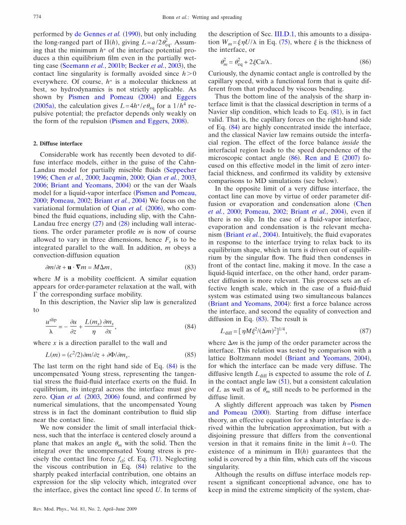
performed by de Gennes et al. �1990�, but only includingthe long-ranged part of ��h�, giving L=a /2�eq
2 . Assum-ing that the minimum h* of the interface potential pro-duces a thin equilibrium film even in the partially wet-ting case �Seemann et al., 2001b; Becker et al., 2003�, thecontact line singularity is formally avoided since h�0everywhere. Of course, h* is a molecular thickness atbest, so hydrodynamics is not strictly applicable. Asshown by Pismen and Pomeau �2004� and Eggers�2005a�, the calculation gives L=4h* /e�eq for a 1/h4 re-pulsive potential; the prefactor depends only weakly onthe form of the repulsion �Pismen and Eggers, 2008�.
2. Diffuse interface
Considerable work has recently been devoted to dif-fuse interface models, either in the guise of the Cahn-Landau model for partially miscible fluids �Seppecher1996; Chen et al., 2000; Jacqmin, 2000; Qian et al., 2003,2006; Briant and Yeomans, 2004� or the van der Waalsmodel for a liquid-vapor interface �Pismen and Pomeau,2000; Pomeau, 2002; Briant et al., 2004� We focus on thevariational formulation of Qian et al. �2006�, who com-bined the fluid equations, including slip, with the Cahn-Landau free energy �27� and �28� including wall interac-tions. The order parameter profile m is now of courseallowed to vary in three dimensions, hence Fs is to beintegrated parallel to the wall. In addition, m obeys aconvection-diffusion equation
�m/�t + u · �m = M�m , �83�
where M is a mobility coefficient. A similar equationappears for order-parameter relaxation at the wall, with� the corresponding surface mobility.
In this description, the Navier slip law is generalizedto
uslip
"= −
�u
�z+
L�ms��
�ms
�x, �84�
where x is a direction parallel to the wall and
L�m� = �c2/2��m/�z + ��/�ms. �85�
The last term on the right hand side of Eq. �84� is theuncompensated Young stress, representing the tangen-tial stress the fluid-fluid interface exerts on the fluid. Inequilibrium, its integral across the interface must givezero. Qian et al. �2003, 2006� found, and confirmed bynumerical simulations, that the uncompensated Youngstress is in fact the dominant contribution to fluid slipnear the contact line.
We now consider the limit of small interfacial thick-ness, such that the interface is centered closely around aplane that makes an angle �m with the solid. Then theintegral over the uncompensated Young stress is pre-cisely the contact line force fcl; cf. Eq. �71�. Neglectingthe viscous contribution in Eq. �84� relative to thesharply peaked interfacial contribution, one obtains anexpression for the slip velocity which, integrated overthe interface, gives the contact line speed U. In terms of
the description of Sec. III.D.1, this amounts to a dissipa-tion Wm=��U /" in Eq. �75�, where � is the thickness ofthe interface, or
�m2 = �eq
2 + 2�Ca/" . �86�
Curiously, the dynamic contact angle is controlled by thecapillary speed, with a functional form that is quite dif-ferent from that produced by viscous bending.
Thus the bottom line of the analysis of the sharp in-terface limit is that the classical description in terms of aNavier slip condition, which leads to Eq. �81�, is in factvalid. That is, the capillary forces on the right-hand sideof Eq. �84� are highly concentrated inside the interface,and the classical Navier law remains outside the interfa-cial region. The effect of the force balance inside theinterfacial region leads to the speed dependence of themicroscopic contact angle �86�. Ren and E �2007� fo-cused on this effective model in the limit of zero inter-facial thickness, and confirmed its validity by extensivecomparisons to MD simulations �see below�.
In the opposite limit of a very diffuse interface, thecontact line can move by virtue of order parameter dif-fusion or evaporation and condensation alone �Chenet al., 2000; Pomeau, 2002; Briant et al., 2004�, even ifthere is no slip. In the case of a fluid-vapor interface,evaporation and condensation is the relevant mecha-nism �Briant et al., 2004�. Intuitively, the fluid evaporatesin response to the interface trying to relax back to itsequilibrium shape, which in turn is driven out of equilib-rium by the singular flow. The fluid then condenses infront of the contact line, making it move. In the case aliquid-liquid interface, on the other hand, order param-eter diffusion is more relevant. This process sets an ef-fective length scale, which in the case of a fluid-fluidsystem was estimated using two simultaneous balances�Briant and Yeomans, 2004�: first a force balance acrossthe interface, and second the equality of convection anddiffusion in Eq. �83�. The result is
Ldiff = �M�2/��m�2�1/4, �87�
where �m is the jump of the order parameter across theinterface. This relation was tested by comparison with alattice Boltzmann model �Briant and Yeomans, 2004�,for which the interface can be made very diffuse. Thediffusive length Ldiff is expected to assume the role of Lin the contact angle law �51�, but a consistent calculationof L as well as of �m still needs to be performed in thediffuse limit.
A slightly different approach was taken by Pismenand Pomeau �2000�. Starting from diffuse interfacetheory, an effective equation for a sharp interface is de-rived within the lubrication approximation, but with adisjoining pressure that differs from the conventionalversion in that it remains finite in the limit h=0. Theexistence of a minimum in ��h� guarantees that thesolid is covered by a thin film, which cuts off the viscoussingularity.
Although the results on diffuse interface models rep-resent a significant conceptional advance, one has tokeep in mind the extreme simplicity of the system, char-
774 Bonn et al.: Wetting and spreading
Rev. Mod. Phys., Vol. 81, No. 2, April–June 2009
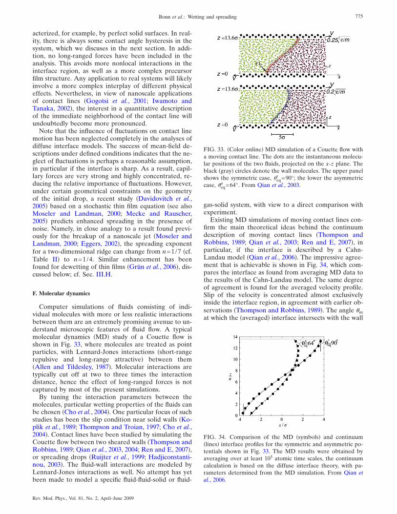
acterized, for example, by perfect solid surfaces. In real-ity, there is always some contact angle hysteresis in thesystem, which we discuses in the next section. In addi-tion, no long-ranged forces have been included in theanalysis. This avoids more nonlocal interactions in theinterface region, as well as a more complex precursorfilm structure. Any application to real systems will likelyinvolve a more complex interplay of different physicaleffects. Nevertheless, in view of nanoscale applicationsof contact lines �Gogotsi et al., 2001; Iwamoto andTanaka, 2002�, the interest in a quantitative descriptionof the immediate neighborhood of the contact line willundoubtedly become more pronounced.
Note that the influence of fluctuations on contact linemotion has been neglected completely in the analyses ofdiffuse interface models. The success of mean-field de-scriptions under defined conditions indicates that the ne-glect of fluctuations is perhaps a reasonable assumption,in particular if the interface is sharp. As a result, capil-lary forces are very strong and highly concentrated, re-ducing the relative importance of fluctuations. However,under certain geometrical constraints on the geometryof the initial drop, a recent study �Davidovitch et al.,2005� based on a stochastic thin film equation �see alsoMoseler and Landman, 2000; Mecke and Rauscher,2005� predicts enhanced spreading in the presence ofnoise. Namely, in close analogy to a result found previ-ously for the breakup of a nanoscale jet �Moseler andLandman, 2000; Eggers, 2002�, the spreading exponentfor a two-dimensional ridge can change from n=1/7 �cf.Table II� to n=1/4. Similar enhancement has beenfound for dewetting of thin films �Grün et al., 2006�, dis-cussed below; cf. Sec. III.H.
F. Molecular dynamics
Computer simulations of fluids consisting of indi-vidual molecules with more or less realistic interactionsbetween them are an extremely promising avenue to un-derstand microscopic features of fluid flow. A typicalmolecular dynamics �MD� study of a Couette flow isshown in Fig. 33, where molecules are treated as pointparticles, with Lennard-Jones interactions �short-rangerepulsive and long-range attractive� between them�Allen and Tildesley, 1987�. Molecular interactions aretypically cut off at two to three times the interactiondistance, hence the effect of long-ranged forces is notcaptured by most of the present simulations.
By tuning the interaction parameters between themolecules, particular wetting properties of the fluids canbe chosen �Cho et al., 2004�. One particular focus of suchstudies has been the slip condition near solid walls �Ko-plik et al., 1989; Thompson and Troian, 1997; Cho et al.,2004�. Contact lines have been studied by simulating theCouette flow between two sheared walls �Thompson andRobbins, 1989; Qian et al., 2003, 2004; Ren and E, 2007�,or spreading drops �Ruijter et al., 1999; Hadjiconstanti-nou, 2003�. The fluid-wall interactions are modeled byLennard-Jones interactions as well. No attempt has yetbeen made to model a specific fluid-fluid-solid or fluid-
gas-solid system, with view to a direct comparison withexperiment.
Existing MD simulations of moving contact lines con-firm the main theoretical ideas behind the continuumdescription of moving contact lines �Thompson andRobbins, 1989; Qian et al., 2003; Ren and E, 2007�, inparticular, if the interface is described by a Cahn-Landau model �Qian et al., 2006�. The impressive agree-ment that is achievable is shown in Fig. 34, which com-pares the interface as found from averaging MD data tothe results of the Cahn-Landau model. The same degreeof agreement is found for the averaged velocity profile.Slip of the velocity is concentrated almost exclusivelyinside the interface region, in agreement with earlier ob-servations �Thompson and Robbins, 1989�. The angle �mat which the �averaged� interface intersects with the wall
FIG. 33. �Color online� MD simulation of a Couette flow witha moving contact line. The dots are the instantaneous molecu-lar positions of the two fluids, projected on the x-z plane. Theblack �gray� circles denote the wall molecules. The upper panelshows the symmetric case, �eq
s =90°; the lower the asymmetriccase, �eq
a =64°. From Qian et al., 2003.
FIG. 34. Comparison of the MD �symbols� and continuum�lines� interface profiles for the symmetric and asymmetric po-tentials shown in Fig. 33. The MD results were obtained byaveraging over at least 105 atomic time scales, the continuumcalculation is based on the diffuse interface theory, with pa-rameters determined from the MD simulation. From Qian etal., 2006.
775Bonn et al.: Wetting and spreading
Rev. Mod. Phys., Vol. 81, No. 2, April–June 2009
is seen to deviate slightly from the equilibrium angles,included in Fig. 34.
The small departures of �m from �eq found in Fig. 34agree well with the continuum modeling, and the corre-sponding analytical result �86�. Similar tests were per-formed by Ren and E �2007�, but for conditions underwhich the departure �m−�eq is much larger. Results areonce more consistent with Eq. �86�. If driven evenharder into the nonlinear regime �Ren and E, 2007�, re-sults are consistent with the functional from of Eq. �79�,predicted by molecular kinetic theory. In addition, theintermediate region of the profile, where viscous bend-ing becomes important, was included in the analysis aswell. The results compare well with Eq. �52� for the vis-cosity ratio M=1, appropriate for the simulation by Renand E �2007�.
It is evident that MD simulations are not well suitedto study macroscopic systems, the most recent simula-tions of contact line flow comprising about 106 particles�Ren and E, 2007�. On the other hand, a hypotheticalMD simulation of a bulk material would not contributemuch additional information: the relative size of fluctua-tions will be quite small. The moving contact line is thusan ideal problem for hybrid numerical schemes�O’Connell and Thompson, 1995; Hadjiconstantinou andPatera, 1997; Hadjiconstantinou, 1999a, 1999b�, in whicha small region around the contact line is treated by anatomistic method, the remaining fluid domain is de-scribed by the Navier-Stokes equation. Information be-tween the two domains is exchanged through an overlapregion. Hadjiconstantinou �1999a, 1999b� showed themethod to work for contact line flows, albeit in systemswhich are still quite small.
G. Receding contact line
We have been careful to point out that the asymptoticsolution �51� applies only to an advancing contact line,which is easily seen from the expression itself. That is, areceding contact line corresponds to Ca�0, hence Eq.�51� does not make sense for x /L→�, since h��x� be-comes negative for ln�x /L��−�m
3 /9Ca. This means thath would eventually become negative, and a completelydifferent description of receding contact lines is neces-sary. The properties of the interface profile for Ca�0are best inferred from an exact solution �Duffy and Wil-son, 1997� of the thin-film equation �49�, expressed interms of Airy functions �Abramowitz and Stegun, 1968�.In the spirit of Sec. III.E, this solution must be matchedto the contact line �Eggers, 2005b�.
In the case of an advancing contact line, the solution isdetermined uniquely by the condition that the curvaturemust vanish at infinity for it to match to an outer solu-tion. Instead, all solutions of Eq. �49� with Ca�0 �reced-ing contact line� have strictly positive curvature at infin-ity. For large x /L one finds �Eggers, 2005b�
h��x� = �x −�3�Ca��1/322/3Ai��s1�
�mAi�s1�+ O�L/x� , �88�
where
� =�3�Ca��1/3 exp�− �m
3 /9�Ca��21/3Ai2�s1�L
� 0 �89�
is the curvature at infinity. The free constant s1 needs tobe found from matching to the meniscus away from thecontact line �Eggers, 2005b�. It is clear from Eq. �88� thatit does not make sense to speak of a dynamic contactangle h��x�, since the slope is varying linearly with x,except at very small capillary numbers, for which thereexists a region ln�x /L�!−�m
3 /9Ca, over which h��x� isstill described by Eq. �51�.
With increasing contact line speed, the curvature crbecomes so large that it becomes impossible to match toan outer solution, leading to a maximum speed Cacr atwhich the contact line can move relative to a plate �Eg-gers, 2004a, 2005b�. Experimentally, this is seen, for ex-ample, by withdrawing a plate from a bath of liquid thatdoes not wet the plate; cf. Fig. 35. Above a maximumspeed of Cacr, no more stationary solutions exist, so thecontact line must move up the plate and a macroscopicfilm is deposited. Strictly speaking, the data shown inFig. 35 were taken from a nonstationary experiment.However, the collapse for different speeds demonstratesthat the contact line moves quasistatically, and effec-tively represents the stationary solution.
Upl
xliquid bath
x cl
x cl
FIG. 35. A plate withdrawn from a bath of nonwetting liquidat speed Upl, which forms a contact line at height zcl. Thecapillary numbers based on the plate speed Upl are Capl=9.7�10−3 ���, Capl=10.2�10−3 ���, Capl=10.7�10−3 ���, Capl=11.2�10−3 ���, and Capl=11.5�10−3 ���. These values areall above the critical capillary number Cacr, so the contact linemoves up very slowly, and each curve is traced out in a time-dependent fashion for each experiment. The full line is foundfrom the thin-film equations �55� and �56�, including gravity.From Delon et al., 2008.
776 Bonn et al.: Wetting and spreading
Rev. Mod. Phys., Vol. 81, No. 2, April–June 2009
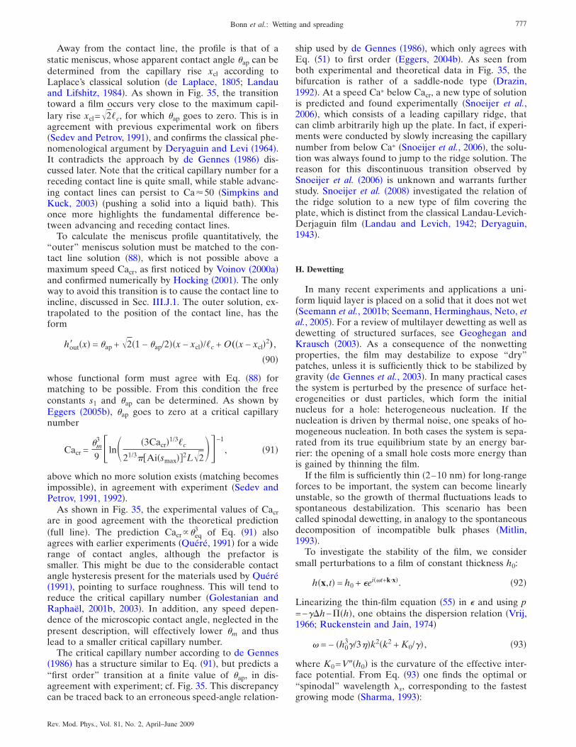
Away from the contact line, the profile is that of astatic meniscus, whose apparent contact angle �ap can bedetermined from the capillary rise xcl according toLaplace’s classical solution �de Laplace, 1805; Landauand Lifshitz, 1984�. As shown in Fig. 35, the transitiontoward a film occurs very close to the maximum capil-lary rise xcl=�2�c, for which �ap goes to zero. This is inagreement with previous experimental work on fibers�Sedev and Petrov, 1991�, and confirms the classical phe-nomenological argument by Deryaguin and Levi �1964�.It contradicts the approach by de Gennes �1986� dis-cussed later. Note that the critical capillary number for areceding contact line is quite small, while stable advanc-ing contact lines can persist to Ca�50 �Simpkins andKuck, 2003� �pushing a solid into a liquid bath�. Thisonce more highlights the fundamental difference be-tween advancing and receding contact lines.
To calculate the meniscus profile quantitatively, the‘‘outer’’ meniscus solution must be matched to the con-tact line solution �88�, which is not possible above amaximum speed Cacr, as first noticed by Voinov �2000a�and confirmed numerically by Hocking �2001�. The onlyway to avoid this transition is to cause the contact line toincline, discussed in Sec. III.J.1. The outer solution, ex-trapolated to the position of the contact line, has theform
hout� �x� = �ap + �2�1 − �ap/2��x − xcl�/�c + O„�x − xcl�2… ,
�90�
whose functional form must agree with Eq. �88� formatching to be possible. From this condition the freeconstants s1 and �ap can be determined. As shown byEggers �2005b�, �ap goes to zero at a critical capillarynumber
Cacr =�m
3
9 �ln� �3Cacr�1/3�c
21/3Ai�smax��2L�2�−1
, �91�
above which no more solution exists �matching becomesimpossible�, in agreement with experiment �Sedev andPetrov, 1991, 1992�.
As shown in Fig. 35, the experimental values of Cacrare in good agreement with the theoretical prediction�full line�. The prediction Cacr�eq
3 of Eq. �91� alsoagrees with earlier experiments �Quéré, 1991� for a widerange of contact angles, although the prefactor issmaller. This might be due to the considerable contactangle hysteresis present for the materials used by Quéré�1991�, pointing to surface roughness. This will tend toreduce the critical capillary number �Golestanian andRaphaël, 2001b, 2003�. In addition, any speed depen-dence of the microscopic contact angle, neglected in thepresent description, will effectively lower �m and thuslead to a smaller critical capillary number.
The critical capillary number according to de Gennes�1986� has a structure similar to Eq. �91�, but predicts a“first order” transition at a finite value of �ap, in dis-agreement with experiment; cf. Fig. 35. This discrepancycan be traced back to an erroneous speed-angle relation-
ship used by de Gennes �1986�, which only agrees withEq. �51� to first order �Eggers, 2004b�. As seen fromboth experimental and theoretical data in Fig. 35, thebifurcation is rather of a saddle-node type �Drazin,1992�. At a speed Ca* below Cacr, a new type of solutionis predicted and found experimentally �Snoeijer et al.,2006�, which consists of a leading capillary ridge, thatcan climb arbitrarily high up the plate. In fact, if experi-ments were conducted by slowly increasing the capillarynumber from below Ca* �Snoeijer et al., 2006�, the solu-tion was always found to jump to the ridge solution. Thereason for this discontinuous transition observed bySnoeijer et al. �2006� is unknown and warrants furtherstudy. Snoeijer et al. �2008� investigated the relation ofthe ridge solution to a new type of film covering theplate, which is distinct from the classical Landau-Levich-Derjaguin film �Landau and Levich, 1942; Deryaguin,1943�.
H. Dewetting
In many recent experiments and applications a uni-form liquid layer is placed on a solid that it does not wet�Seemann et al., 2001b; Seemann, Herminghaus, Neto, etal., 2005�. For a review of multilayer dewetting as well asdewetting of structured surfaces, see Geoghegan andKrausch �2003�. As a consequence of the nonwettingproperties, the film may destabilize to expose “dry”patches, unless it is sufficiently thick to be stabilized bygravity �de Gennes et al., 2003�. In many practical casesthe system is perturbed by the presence of surface het-erogeneities or dust particles, which form the initialnucleus for a hole: heterogeneous nucleation. If thenucleation is driven by thermal noise, one speaks of ho-mogeneous nucleation. In both cases the system is sepa-rated from its true equilibrium state by an energy bar-rier: the opening of a small hole costs more energy thanis gained by thinning the film.
If the film is sufficiently thin �2–10 nm� for long-rangeforces to be important, the system can become linearlyunstable, so the growth of thermal fluctuations leads tospontaneous destabilization. This scenario has beencalled spinodal dewetting, in analogy to the spontaneousdecomposition of incompatible bulk phases �Mitlin,1993�.
To investigate the stability of the film, we considersmall perturbations to a film of constant thickness h0:
h�x,t� = h0 + �ei��t+k·x�. �92�
Linearizing the thin-film equation �55� in � and using p=−��h−��h�, one obtains the dispersion relation �Vrij,1966; Ruckenstein and Jain, 1974�
� = − �h03�/3��k2�k2 + K0/�� , �93�
where K0=V��h0� is the curvature of the effective inter-face potential. From Eq. �93� one finds the optimal or“spinodal” wavelength "s, corresponding to the fastestgrowing mode �Sharma, 1993�:
777Bonn et al.: Wetting and spreading
Rev. Mod. Phys., Vol. 81, No. 2, April–June 2009
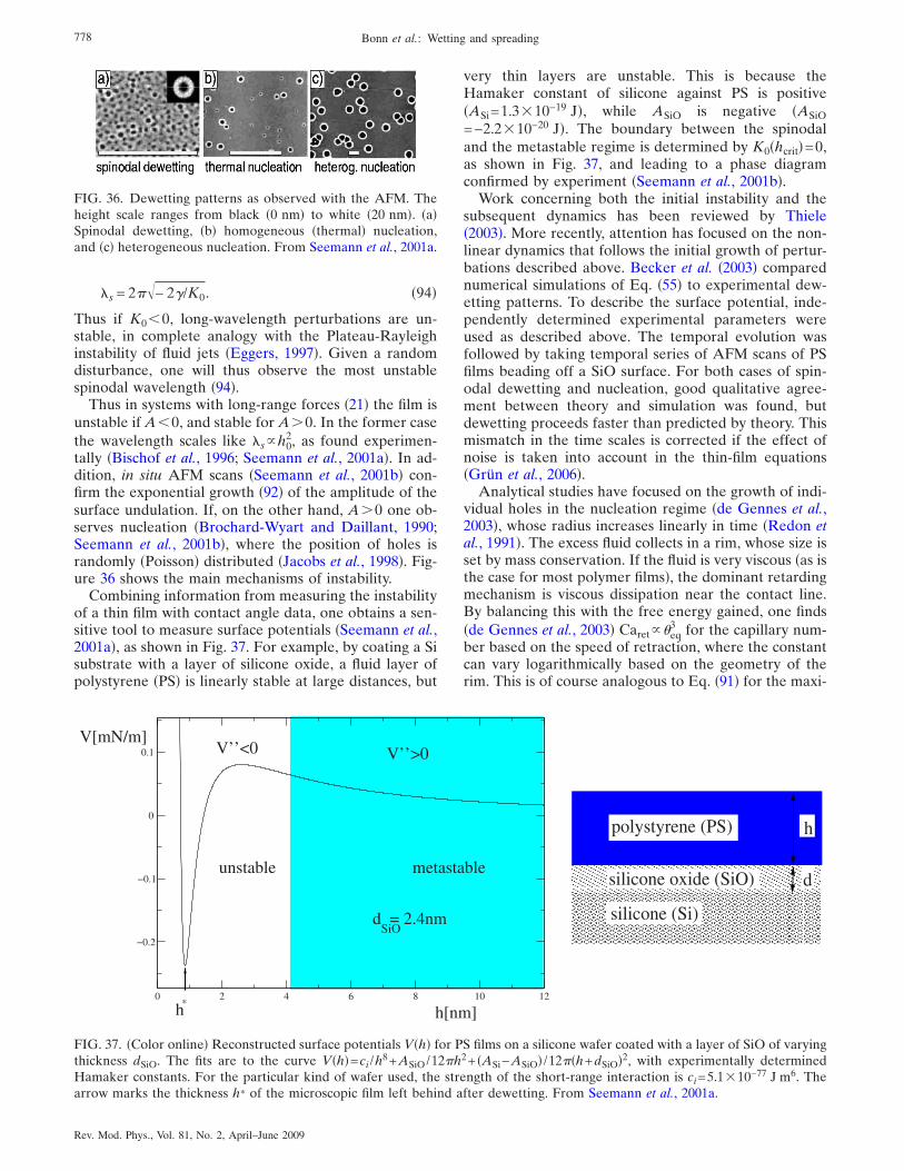
"s = 2�− 2�/K0. �94�
Thus if K0�0, long-wavelength perturbations are un-stable, in complete analogy with the Plateau-Rayleighinstability of fluid jets �Eggers, 1997�. Given a randomdisturbance, one will thus observe the most unstablespinodal wavelength �94�.
Thus in systems with long-range forces �21� the film isunstable if A�0, and stable for A�0. In the former casethe wavelength scales like "sh0
2, as found experimen-tally �Bischof et al., 1996; Seemann et al., 2001a�. In ad-dition, in situ AFM scans �Seemann et al., 2001b� con-firm the exponential growth �92� of the amplitude of thesurface undulation. If, on the other hand, A�0 one ob-serves nucleation �Brochard-Wyart and Daillant, 1990;Seemann et al., 2001b�, where the position of holes israndomly �Poisson� distributed �Jacobs et al., 1998�. Fig-ure 36 shows the main mechanisms of instability.
Combining information from measuring the instabilityof a thin film with contact angle data, one obtains a sen-sitive tool to measure surface potentials �Seemann et al.,2001a�, as shown in Fig. 37. For example, by coating a Sisubstrate with a layer of silicone oxide, a fluid layer ofpolystyrene �PS� is linearly stable at large distances, but
very thin layers are unstable. This is because theHamaker constant of silicone against PS is positive�ASi=1.3�10−19 J�, while ASiO is negative �ASiO=−2.2�10−20 J�. The boundary between the spinodaland the metastable regime is determined by K0�hcrit�=0,as shown in Fig. 37, and leading to a phase diagramconfirmed by experiment �Seemann et al., 2001b�.
Work concerning both the initial instability and thesubsequent dynamics has been reviewed by Thiele�2003�. More recently, attention has focused on the non-linear dynamics that follows the initial growth of pertur-bations described above. Becker et al. �2003� comparednumerical simulations of Eq. �55� to experimental dew-etting patterns. To describe the surface potential, inde-pendently determined experimental parameters wereused as described above. The temporal evolution wasfollowed by taking temporal series of AFM scans of PSfilms beading off a SiO surface. For both cases of spin-odal dewetting and nucleation, good qualitative agree-ment between theory and simulation was found, butdewetting proceeds faster than predicted by theory. Thismismatch in the time scales is corrected if the effect ofnoise is taken into account in the thin-film equations�Grün et al., 2006�.
Analytical studies have focused on the growth of indi-vidual holes in the nucleation regime �de Gennes et al.,2003�, whose radius increases linearly in time �Redon etal., 1991�. The excess fluid collects in a rim, whose size isset by mass conservation. If the fluid is very viscous �as isthe case for most polymer films�, the dominant retardingmechanism is viscous dissipation near the contact line.By balancing this with the free energy gained, one finds�de Gennes et al., 2003� Caret�eq
3 for the capillary num-ber based on the speed of retraction, where the constantcan vary logarithmically based on the geometry of therim. This is of course analogous to Eq. �91� for the maxi-
FIG. 36. Dewetting patterns as observed with the AFM. Theheight scale ranges from black �0 nm� to white �20 nm�. �a�Spinodal dewetting, �b� homogeneous �thermal� nucleation,and �c� heterogeneous nucleation. From Seemann et al., 2001a.
0 2 4 6 8 10 12
−0.2
−0.1
0
0.1
*
� � � � � � � � � � � � � � � � � �� � � � � � � � � � � � � � � � � �� � � � � � � � � � � � � � � � � ��
� � � � � � � � � � � � � � � � � �� � � � � � � � � � � � � � � � � �� � � � � � � � � � � � � � � � � �� � � � � � � � � � � � � � � � � �� � � � � � � � � � � � � � � � � �� � � � � � � � � � � � � � � � � �� � � � � � � � � � � � � � � � � �
polystyrene (PS)
silicone oxide (SiO)
silicone (Si)
h
d
h[nm]
V’’>0
metastableunstable
d = 2.4nmSiO
V’’<0
h
V[mN/m]
FIG. 37. �Color online� Reconstructed surface potentials V�h� for PS films on a silicone wafer coated with a layer of SiO of varyingthickness dSiO. The fits are to the curve V�h�=ci /h8+ASiO/12h2+ �ASi−ASiO� /12�h+dSiO�2, with experimentally determinedHamaker constants. For the particular kind of wafer used, the strength of the short-range interaction is ci=5.1�10−77 J m6. Thearrow marks the thickness h* of the microscopic film left behind after dewetting. From Seemann et al., 2001a.
778 Bonn et al.: Wetting and spreading
Rev. Mod. Phys., Vol. 81, No. 2, April–June 2009
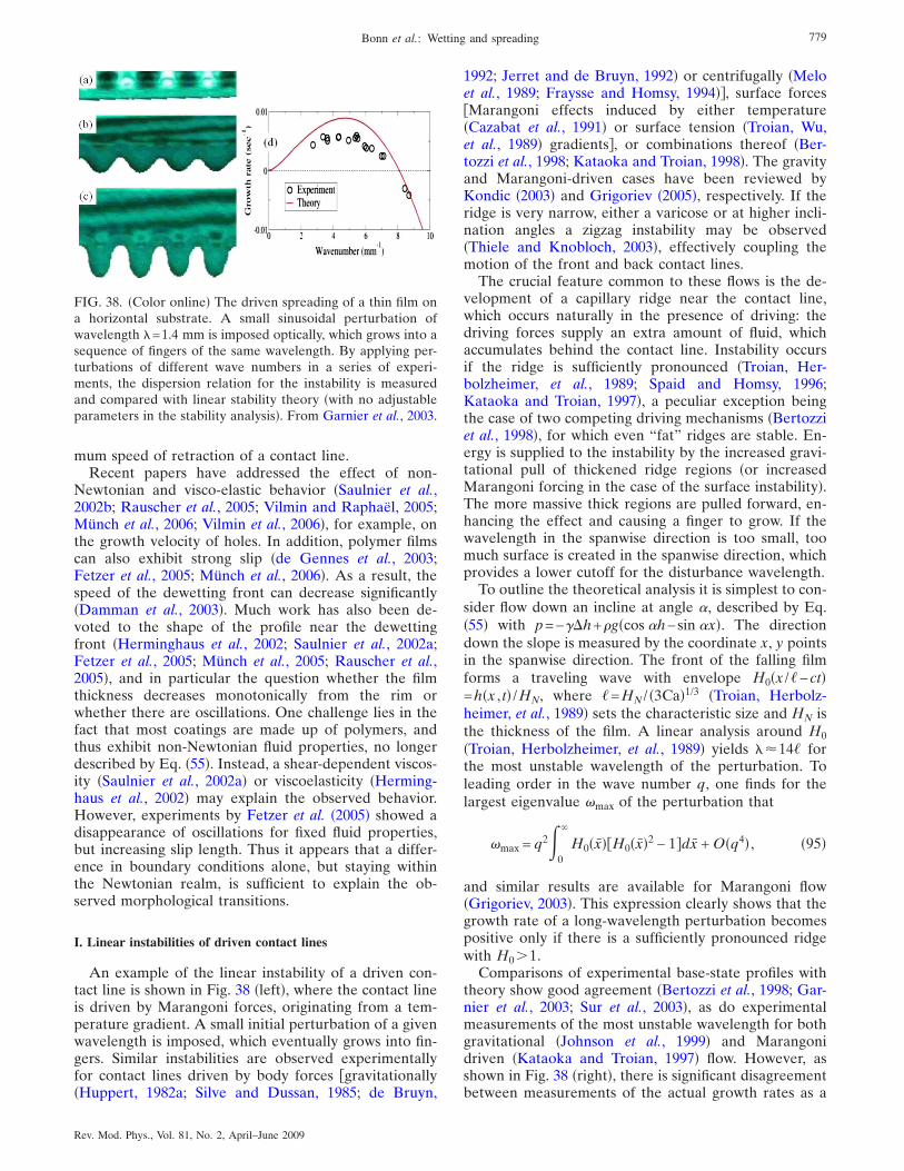
mum speed of retraction of a contact line.Recent papers have addressed the effect of non-
Newtonian and visco-elastic behavior �Saulnier et al.,2002b; Rauscher et al., 2005; Vilmin and Raphaël, 2005;Münch et al., 2006; Vilmin et al., 2006�, for example, onthe growth velocity of holes. In addition, polymer filmscan also exhibit strong slip �de Gennes et al., 2003;Fetzer et al., 2005; Münch et al., 2006�. As a result, thespeed of the dewetting front can decrease significantly�Damman et al., 2003�. Much work has also been de-voted to the shape of the profile near the dewettingfront �Herminghaus et al., 2002; Saulnier et al., 2002a;Fetzer et al., 2005; Münch et al., 2005; Rauscher et al.,2005�, and in particular the question whether the filmthickness decreases monotonically from the rim orwhether there are oscillations. One challenge lies in thefact that most coatings are made up of polymers, andthus exhibit non-Newtonian fluid properties, no longerdescribed by Eq. �55�. Instead, a shear-dependent viscos-ity �Saulnier et al., 2002a� or viscoelasticity �Herming-haus et al., 2002� may explain the observed behavior.However, experiments by Fetzer et al. �2005� showed adisappearance of oscillations for fixed fluid properties,but increasing slip length. Thus it appears that a differ-ence in boundary conditions alone, but staying withinthe Newtonian realm, is sufficient to explain the ob-served morphological transitions.
I. Linear instabilities of driven contact lines
An example of the linear instability of a driven con-tact line is shown in Fig. 38 �left�, where the contact lineis driven by Marangoni forces, originating from a tem-perature gradient. A small initial perturbation of a givenwavelength is imposed, which eventually grows into fin-gers. Similar instabilities are observed experimentallyfor contact lines driven by body forces gravitationally�Huppert, 1982a; Silve and Dussan, 1985; de Bruyn,
1992; Jerret and de Bruyn, 1992� or centrifugally �Meloet al., 1989; Fraysse and Homsy, 1994��, surface forcesMarangoni effects induced by either temperature�Cazabat et al., 1991� or surface tension �Troian, Wu,et al., 1989� gradients�, or combinations thereof �Ber-tozzi et al., 1998; Kataoka and Troian, 1998�. The gravityand Marangoni-driven cases have been reviewed byKondic �2003� and Grigoriev �2005�, respectively. If theridge is very narrow, either a varicose or at higher incli-nation angles a zigzag instability may be observed�Thiele and Knobloch, 2003�, effectively coupling themotion of the front and back contact lines.
The crucial feature common to these flows is the de-velopment of a capillary ridge near the contact line,which occurs naturally in the presence of driving: thedriving forces supply an extra amount of fluid, whichaccumulates behind the contact line. Instability occursif the ridge is sufficiently pronounced �Troian, Her-bolzheimer, et al., 1989; Spaid and Homsy, 1996;Kataoka and Troian, 1997�, a peculiar exception beingthe case of two competing driving mechanisms �Bertozziet al., 1998�, for which even “fat” ridges are stable. En-ergy is supplied to the instability by the increased gravi-tational pull of thickened ridge regions �or increasedMarangoni forcing in the case of the surface instability�.The more massive thick regions are pulled forward, en-hancing the effect and causing a finger to grow. If thewavelength in the spanwise direction is too small, toomuch surface is created in the spanwise direction, whichprovides a lower cutoff for the disturbance wavelength.
To outline the theoretical analysis it is simplest to con-sider flow down an incline at angle �, described by Eq.�55� with p=−��h+�g�cos �h−sin �x�. The directiondown the slope is measured by the coordinate x, y pointsin the spanwise direction. The front of the falling filmforms a traveling wave with envelope H0�x /�−ct�=h�x , t� /HN, where �=HN / �3Ca�1/3 �Troian, Herbolz-heimer, et al., 1989� sets the characteristic size and HN isthe thickness of the film. A linear analysis around H0�Troian, Herbolzheimer, et al., 1989� yields "�14� forthe most unstable wavelength of the perturbation. Toleading order in the wave number q, one finds for thelargest eigenvalue �max of the perturbation that
�max = q2 0
�
H0�x�H0�x�2 − 1�dx + O�q4� , �95�
and similar results are available for Marangoni flow�Grigoriev, 2003�. This expression clearly shows that thegrowth rate of a long-wavelength perturbation becomespositive only if there is a sufficiently pronounced ridgewith H0�1.
Comparisons of experimental base-state profiles withtheory show good agreement �Bertozzi et al., 1998; Gar-nier et al., 2003; Sur et al., 2003�, as do experimentalmeasurements of the most unstable wavelength for bothgravitational �Johnson et al., 1999� and Marangonidriven �Kataoka and Troian, 1997� flow. However, asshown in Fig. 38 �right�, there is significant disagreementbetween measurements of the actual growth rates as a
FIG. 38. �Color online� The driven spreading of a thin film ona horizontal substrate. A small sinusoidal perturbation ofwavelength "=1.4 mm is imposed optically, which grows into asequence of fingers of the same wavelength. By applying per-turbations of different wave numbers in a series of experi-ments, the dispersion relation for the instability is measuredand compared with linear stability theory �with no adjustableparameters in the stability analysis�. From Garnier et al., 2003.
779Bonn et al.: Wetting and spreading
Rev. Mod. Phys., Vol. 81, No. 2, April–June 2009
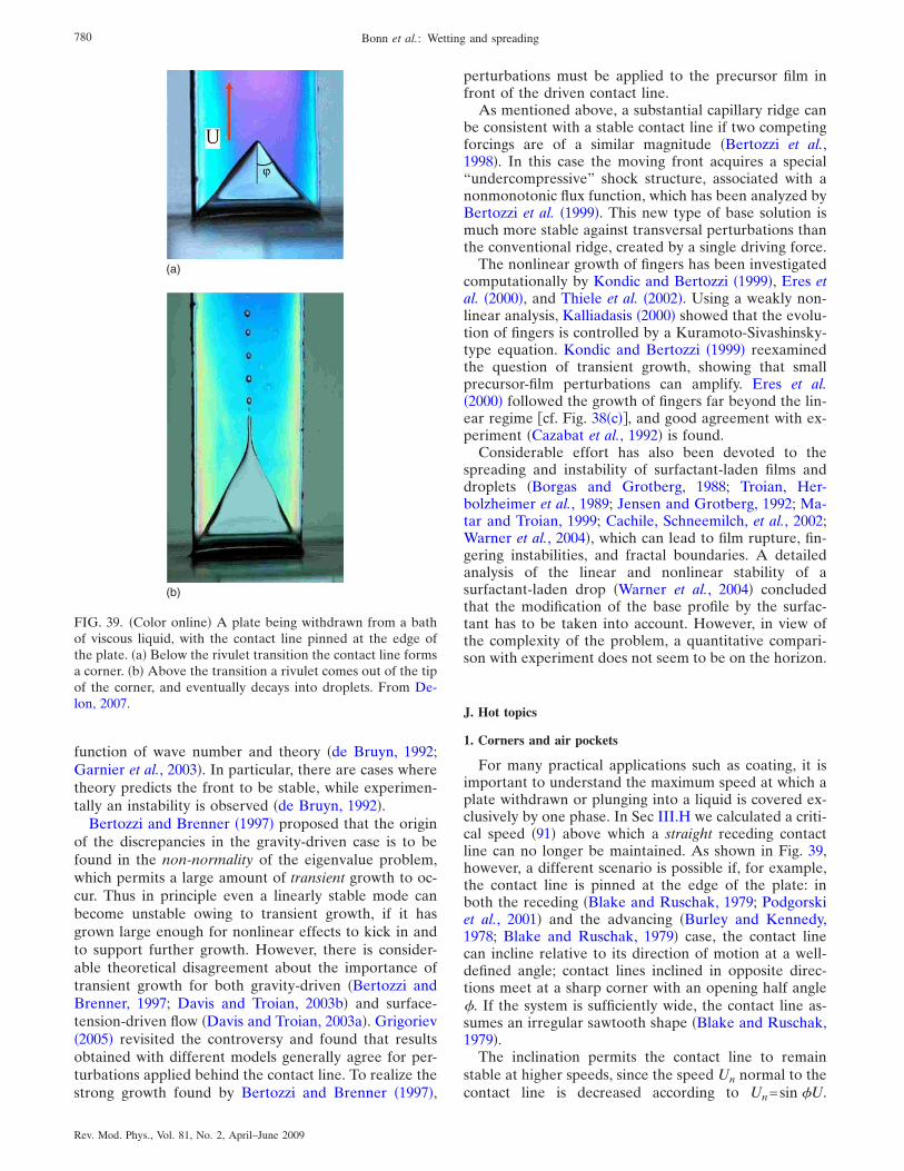
function of wave number and theory �de Bruyn, 1992;Garnier et al., 2003�. In particular, there are cases wheretheory predicts the front to be stable, while experimen-tally an instability is observed �de Bruyn, 1992�.
Bertozzi and Brenner �1997� proposed that the originof the discrepancies in the gravity-driven case is to befound in the non-normality of the eigenvalue problem,which permits a large amount of transient growth to oc-cur. Thus in principle even a linearly stable mode canbecome unstable owing to transient growth, if it hasgrown large enough for nonlinear effects to kick in andto support further growth. However, there is consider-able theoretical disagreement about the importance oftransient growth for both gravity-driven �Bertozzi andBrenner, 1997; Davis and Troian, 2003b� and surface-tension-driven flow �Davis and Troian, 2003a�. Grigoriev�2005� revisited the controversy and found that resultsobtained with different models generally agree for per-turbations applied behind the contact line. To realize thestrong growth found by Bertozzi and Brenner �1997�,
perturbations must be applied to the precursor film infront of the driven contact line.
As mentioned above, a substantial capillary ridge canbe consistent with a stable contact line if two competingforcings are of a similar magnitude �Bertozzi et al.,1998�. In this case the moving front acquires a special“undercompressive” shock structure, associated with anonmonotonic flux function, which has been analyzed byBertozzi et al. �1999�. This new type of base solution ismuch more stable against transversal perturbations thanthe conventional ridge, created by a single driving force.
The nonlinear growth of fingers has been investigatedcomputationally by Kondic and Bertozzi �1999�, Eres etal. �2000�, and Thiele et al. �2002�. Using a weakly non-linear analysis, Kalliadasis �2000� showed that the evolu-tion of fingers is controlled by a Kuramoto-Sivashinsky-type equation. Kondic and Bertozzi �1999� reexaminedthe question of transient growth, showing that smallprecursor-film perturbations can amplify. Eres et al.�2000� followed the growth of fingers far beyond the lin-ear regime cf. Fig. 38�c��, and good agreement with ex-periment �Cazabat et al., 1992� is found.
Considerable effort has also been devoted to thespreading and instability of surfactant-laden films anddroplets �Borgas and Grotberg, 1988; Troian, Her-bolzheimer et al., 1989; Jensen and Grotberg, 1992; Ma-tar and Troian, 1999; Cachile, Schneemilch, et al., 2002;Warner et al., 2004�, which can lead to film rupture, fin-gering instabilities, and fractal boundaries. A detailedanalysis of the linear and nonlinear stability of asurfactant-laden drop �Warner et al., 2004� concludedthat the modification of the base profile by the surfac-tant has to be taken into account. However, in view ofthe complexity of the problem, a quantitative compari-son with experiment does not seem to be on the horizon.
J. Hot topics
1. Corners and air pockets
For many practical applications such as coating, it isimportant to understand the maximum speed at which aplate withdrawn or plunging into a liquid is covered ex-clusively by one phase. In Sec III.H we calculated a criti-cal speed �91� above which a straight receding contactline can no longer be maintained. As shown in Fig. 39,however, a different scenario is possible if, for example,the contact line is pinned at the edge of the plate: inboth the receding �Blake and Ruschak, 1979; Podgorskiet al., 2001� and the advancing �Burley and Kennedy,1978; Blake and Ruschak, 1979� case, the contact linecan incline relative to its direction of motion at a well-defined angle; contact lines inclined in opposite direc-tions meet at a sharp corner with an opening half angle#. If the system is sufficiently wide, the contact line as-sumes an irregular sawtooth shape �Blake and Ruschak,1979�.
The inclination permits the contact line to remainstable at higher speeds, since the speed Un normal to thecontact line is decreased according to Un=sin #U.
(b)
(a)
FIG. 39. �Color online� A plate being withdrawn from a bathof viscous liquid, with the contact line pinned at the edge ofthe plate. �a� Below the rivulet transition the contact line formsa corner. �b� Above the transition a rivulet comes out of the tipof the corner, and eventually decays into droplets. From De-lon, 2007.
780 Bonn et al.: Wetting and spreading
Rev. Mod. Phys., Vol. 81, No. 2, April–June 2009
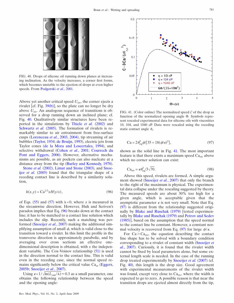
Above yet another critical speed Uriv, the corner ejects arivulet cf. Fig. 39�b��, so the plate can no longer be dryabove Uriv. An analogous sequence of transitions is ob-served for a drop running down an inclined plane; cf.Fig. 40. Qualitatively similar structures have been re-ported in the simulations by Thiele et al. �2002� andSchwartz et al. �2005�. The formation of rivulets is re-markably similar to air entrainment from free-surfacecusps �Lorenceau et al., 2003, 2004�, tip streaming of airbubbles �Taylor, 1934; de Bruijn, 1993�, electric jets fromTaylor cones �de la Mora and Loscertales, 1994�, andselective withdrawal �Cohen et al., 2001; Courrech duPont and Eggers, 2006�. However, alternative mecha-nisms are possible, as air pockets can also nucleate at adistance away from the tip �Burley and Kennedy, 1978�.
Stone et al. �2002�, Limat and Stone �2003�, and Snoe-ijer et al. �2005� found that the triangular shape of areceding contact line is described by a similarity solu-tion,
h�x,y� = Ca1/3xH�y/x� , �96�
of Eqs. �55� and �57� with "=0, where x is measured inthe streamwise direction. However, Huh and Scriven’sparadox implies that Eq. �96� breaks down at the contactline; it has to be matched to a contact line solution whichincludes the slip. Recently, such a matching was per-formed �Snoeijer et al., 2007� making the additional sim-plifying assumption of small #, which is valid close to thetransition toward a rivulet. In this limit the profile in thetransverse direction is approximately parabolic, and byaveraging over cross sections an effective one-dimensional description is obtained, with x the indepen-dent variable. The Cox-Voinov relationship �51� is usedin the direction normal to the contact line. This is valideven in the receding case, since the normal speed re-mains significantly below the critical value Cacr �Eggers,2005b; Snoeijer et al., 2007�.
Using �=1/�ln�Lout /"��0.3 as a small parameter, oneobtains the following relationship between the speedand the opening angle:
Ca = 2�eq3 #/35 + 18�#/��2� , �97�
shown as the solid line in Fig. 41. The most importantfeature is that there exists a maximum speed Cariv abovewhich no corner solution can exist:
Cariv = ��eq3 /3�70. �98�
Above this speed, rivulets are formed. A simple argu-ment showed �Snoeijer et al., 2007� that only the branchto the right of the maximum is physical. The experimen-tal data collapse under the rescaling suggested by theory.The measured speeds are about 30% too high for agiven angle, which is acceptable given that theasymptotic parameter � is not very small. Note that Eq.�97� is different from the relationship suggested origi-nally by Blake and Ruschak �1979� tested experimen-tally by Blake and Ruschak �1979� and Petrov and Sedev�1985��, based on the assumption that the speed normalto the contact line be constant. However, a constant nor-mal velocity is recovered from Eq. �97� for large # /�.
For Ca�Cariv, the equation describing the contactline shape has to be solved with a boundary conditioncorresponding to a rivulet of constant width �Snoeijer etal., 2007�. Curiously, it is found that the rivulet widthcannot be fixed by local parameters alone, but some ex-ternal length scale is needed. In the case of the runningdrop treated experimentally by Snoeijer et al. �2007� �cf.Fig. 40�, this length is the drop size. Good agreementwith experimental measurements of the rivulet widthwas found, except very close to Cariv, where the width isexpected to go to zero. A possible reason is that near thetransition drops are ejected almost directly from the tip,
FIG. 40. Drops of silicone oil running down planes at increas-ing inclination. As the velocity increases, a corner first forms,which becomes unstable to the ejection of drops at even higherspeeds. From Podgorski et al., 2001.
FIG. 41. �Color online� The normalized speed C of the drop asfunction of the normalized opening angle �. Symbols repre-sent rescaled experimental data for silicone oils with viscosities10, 104, and 1040 cP. Data were rescaled using the recedingstatic contact angle �r.
781Bonn et al.: Wetting and spreading
Rev. Mod. Phys., Vol. 81, No. 2, April–June 2009
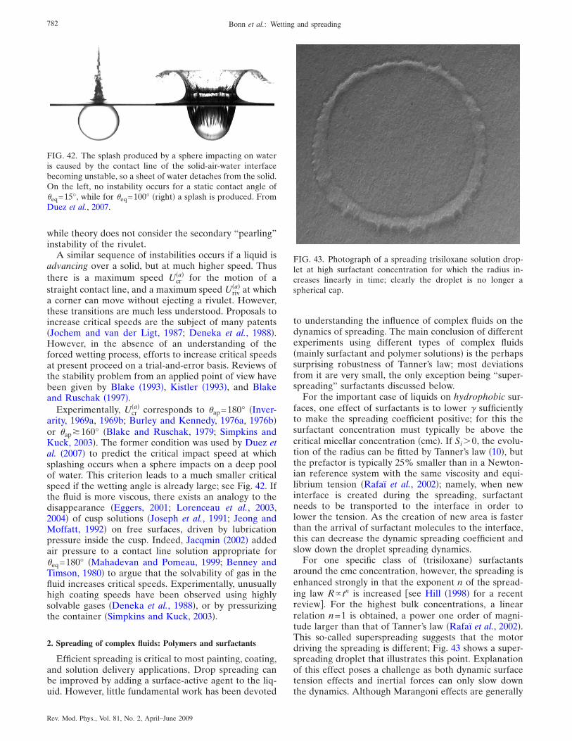
while theory does not consider the secondary “pearling”instability of the rivulet.
A similar sequence of instabilities occurs if a liquid isadvancing over a solid, but at much higher speed. Thusthere is a maximum speed Ucr
�a� for the motion of astraight contact line, and a maximum speed Uriv
�a� at whicha corner can move without ejecting a rivulet. However,these transitions are much less understood. Proposals toincrease critical speeds are the subject of many patents�Jochem and van der Ligt, 1987; Deneka et al., 1988�.However, in the absence of an understanding of theforced wetting process, efforts to increase critical speedsat present proceed on a trial-and-error basis. Reviews ofthe stability problem from an applied point of view havebeen given by Blake �1993�, Kistler �1993�, and Blakeand Ruschak �1997�.
Experimentally, Ucr�a� corresponds to �ap=180° �Inver-
arity, 1969a, 1969b; Burley and Kennedy, 1976a, 1976b�or �ap�160° �Blake and Ruschak, 1979; Simpkins andKuck, 2003�. The former condition was used by Duez etal. �2007� to predict the critical impact speed at whichsplashing occurs when a sphere impacts on a deep poolof water. This criterion leads to a much smaller criticalspeed if the wetting angle is already large; see Fig. 42. Ifthe fluid is more viscous, there exists an analogy to thedisappearance �Eggers, 2001; Lorenceau et al., 2003,2004� of cusp solutions �Joseph et al., 1991; Jeong andMoffatt, 1992� on free surfaces, driven by lubricationpressure inside the cusp. Indeed, Jacqmin �2002� addedair pressure to a contact line solution appropriate for�eq=180° �Mahadevan and Pomeau, 1999; Benney andTimson, 1980� to argue that the solvability of gas in thefluid increases critical speeds. Experimentally, unusuallyhigh coating speeds have been observed using highlysolvable gases �Deneka et al., 1988�, or by pressurizingthe container �Simpkins and Kuck, 2003�.
2. Spreading of complex fluids: Polymers and surfactants
Efficient spreading is critical to most painting, coating,and solution delivery applications, Drop spreading canbe improved by adding a surface-active agent to the liq-uid. However, little fundamental work has been devoted
to understanding the influence of complex fluids on thedynamics of spreading. The main conclusion of differentexperiments using different types of complex fluids�mainly surfactant and polymer solutions� is the perhapssurprising robustness of Tanner’s law; most deviationsfrom it are very small, the only exception being “super-spreading” surfactants discussed below.
For the important case of liquids on hydrophobic sur-faces, one effect of surfactants is to lower � sufficientlyto make the spreading coefficient positive; for this thesurfactant concentration must typically be above thecritical micellar concentration �cmc�. If Si�0, the evolu-tion of the radius can be fitted by Tanner’s law �10�, butthe prefactor is typically 25% smaller than in a Newton-ian reference system with the same viscosity and equi-librium tension �Rafaï et al., 2002�; namely, when newinterface is created during the spreading, surfactantneeds to be transported to the interface in order tolower the tension. As the creation of new area is fasterthan the arrival of surfactant molecules to the interface,this can decrease the dynamic spreading coefficient andslow down the droplet spreading dynamics.
For one specific class of �trisiloxane� surfactantsaround the cmc concentration, however, the spreading isenhanced strongly in that the exponent n of the spread-ing law R tn is increased see Hill �1998� for a recentreview�. For the highest bulk concentrations, a linearrelation n=1 is obtained, a power one order of magni-tude larger than that of Tanner’s law �Rafaï et al., 2002�.This so-called superspreading suggests that the motordriving the spreading is different; Fig. 43 shows a super-spreading droplet that illustrates this point. Explanationof this effect poses a challenge as both dynamic surfacetension effects and inertial forces can only slow downthe dynamics. Although Marangoni effects are generally
FIG. 42. The splash produced by a sphere impacting on wateris caused by the contact line of the solid-air-water interfacebecoming unstable, so a sheet of water detaches from the solid.On the left, no instability occurs for a static contact angle of�eq=15°, while for �eq=100° �right� a splash is produced. FromDuez et al., 2007.
FIG. 43. Photograph of a spreading trisiloxane solution drop-let at high surfactant concentration for which the radius in-creases linearly in time; clearly the droplet is no longer aspherical cap.
782 Bonn et al.: Wetting and spreading
Rev. Mod. Phys., Vol. 81, No. 2, April–June 2009
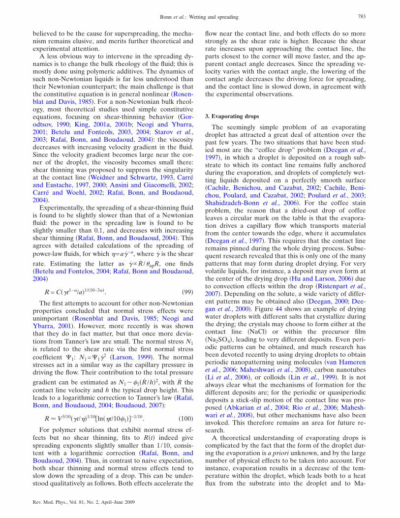
believed to be the cause for superspreading, the mecha-nism remains elusive, and merits further theoretical andexperimental attention.
A less obvious way to intervene in the spreading dy-namics is to change the bulk rheology of the fluid; this ismostly done using polymeric additives. The dynamics ofsuch non-Newtonian liquids is far less understood thantheir Newtonian counterpart; the main challenge is thatthe constitutive equation is in general nonlinear �Rosen-blat and Davis, 1985�. For a non-Newtonian bulk rheol-ogy, most theoretical studies used simple constitutiveequations, focusing on shear-thinning behavior �Gor-odtsov, 1990; King, 2001a, 2001b; Neogi and Ybarra,2001; Betelu and Fonteols, 2003, 2004; Starov et al.,2003; Rafaï, Bonn, and Boudaoud, 2004�: the viscositydecreases with increasing velocity gradient in the fluid.Since the velocity gradient becomes large near the cor-ner of the droplet, the viscosity becomes small there:shear thinning was proposed to suppress the singularityat the contact line �Weidner and Schwartz, 1993, Carréand Eustache, 1997, 2000; Ansini and Giacomelli, 2002;Carré and Woehl, 2002; Rafaï, Bonn, and Boudaoud,2004�.
Experimentally, the spreading of a shear-thinning fluidis found to be slightly slower than that of a Newtonianfluid: the power in the spreading law is found to beslightly smaller than 0.1, and decreases with increasingshear thinning �Rafaï, Bonn, and Boudaoud, 2004�. Thisagrees with detailed calculations of the spreading ofpower-law fluids, for which �=a�−�, where � is the shear
rate. Estimating the latter as � R /�apR, one finds�Betelu and Fontelos, 2004; Rafaï, Bonn and Boudaoud,2004�
R = C��t1−�/a�1/�10−3��. �99�
The first attempts to account for other non-Newtonianproperties concluded that normal stress effects wereunimportant �Rosenblat and Davis, 1985; Neogi andYbarra, 2001�. However, more recently is was shownthat they do in fact matter, but that once more devia-tions from Tanner’s law are small. The normal stress N1is related to the shear rate via the first normal stresscoefficient &1: N1=&1�
2 �Larson, 1999�. The normalstresses act in a similar way as the capillary pressure indriving the flow. Their contribution to the total pressure
gradient can be estimated as N1��1�R /h�2, with R thecontact line velocity and h the typical drop height. Thisleads to a logarithmic correction to Tanner’s law �Rafaï,Bonn, and Boudaoud, 2004; Boudaoud, 2007�:
R � V3/10��t/��1/10ln��t/10�1��−1/10. �100�
For polymer solutions that exhibit normal stress ef-fects but no shear thinning, fits to R�t� indeed givespreading exponents slightly smaller than 1/10, consis-tent with a logarithmic correction �Rafaï, Bonn, andBoudaoud, 2004�. Thus, in contrast to naive expectation,both shear thinning and normal stress effects tend toslow down the spreading of a drop. This can be under-stood qualitatively as follows. Both effects accelerate the
flow near the contact line, and both effects do so morestrongly as the shear rate is higher. Because the shearrate increases upon approaching the contact line, theparts closest to the corner will move faster, and the ap-parent contact angle decreases. Since the spreading ve-locity varies with the contact angle, the lowering of thecontact angle decreases the driving force for spreading,and the contact line is slowed down, in agreement withthe experimental observations.
3. Evaporating drops
The seemingly simple problem of an evaporatingdroplet has attracted a great deal of attention over thepast few years. The two situations that have been stud-ied most are the “coffee drop” problem �Deegan et al.,1997�, in which a droplet is deposited on a rough sub-strate to which its contact line remains fully anchoredduring the evaporation, and droplets of completely wet-ting liquids deposited on a perfectly smooth surface�Cachile, Benichou, and Cazabat, 2002; Cachile, Beni-chou, Poulard, and Cazabat, 2002; Poulard et al., 2003;Shahidzadeh-Bonn et al., 2006�. For the coffee stainproblem, the reason that a dried-out drop of coffeeleaves a circular mark on the table is that the evapora-tion drives a capillary flow which transports materialfrom the center towards the edge, where it accumulates�Deegan et al., 1997�. This requires that the contact lineremains pinned during the whole drying process. Subse-quent research revealed that this is only one of the manypatterns that may form during droplet drying. For veryvolatile liquids, for instance, a deposit may even form atthe center of the drying drop �Hu and Larson, 2006� dueto convection effects within the drop �Ristenpart et al.,2007�. Depending on the solute, a wide variety of differ-ent patterns may be obtained also �Deegan, 2000; Dee-gan et al., 2000�. Figure 44 shows an example of dryingwater droplets with different salts that crystallize duringthe drying; the crystals may choose to form either at thecontact line �NaCl� or within the precursor film�Na2SO4�, leading to very different deposits. Even peri-odic patterns can be obtained, and much research hasbeen devoted recently to using drying droplets to obtainperiodic nanopatterning using molecules �van Hamerenet al., 2006; Maheshwari et al., 2008�, carbon nanotubes�Li et al., 2006�, or colloids �Lin et al., 1999�. It is notalways clear what the mechanisms of formation for thedifferent deposits are; for the periodic or quasiperiodicdeposits a stick-slip motion of the contact line was pro-posed �Abkarian et al., 2004; Rio et al., 2006; Mahesh-wari et al., 2008�, but other mechanisms have also beeninvoked. This therefore remains an area for future re-search.
A theoretical understanding of evaporating drops iscomplicated by the fact that the form of the droplet dur-ing the evaporation is a priori unknown, and by the largenumber of physical effects to be taken into account. Forinstance, evaporation results in a decrease of the tem-perature within the droplet, which leads both to a heatflux from the substrate into the droplet and to Ma-
783Bonn et al.: Wetting and spreading
Rev. Mod. Phys., Vol. 81, No. 2, April–June 2009
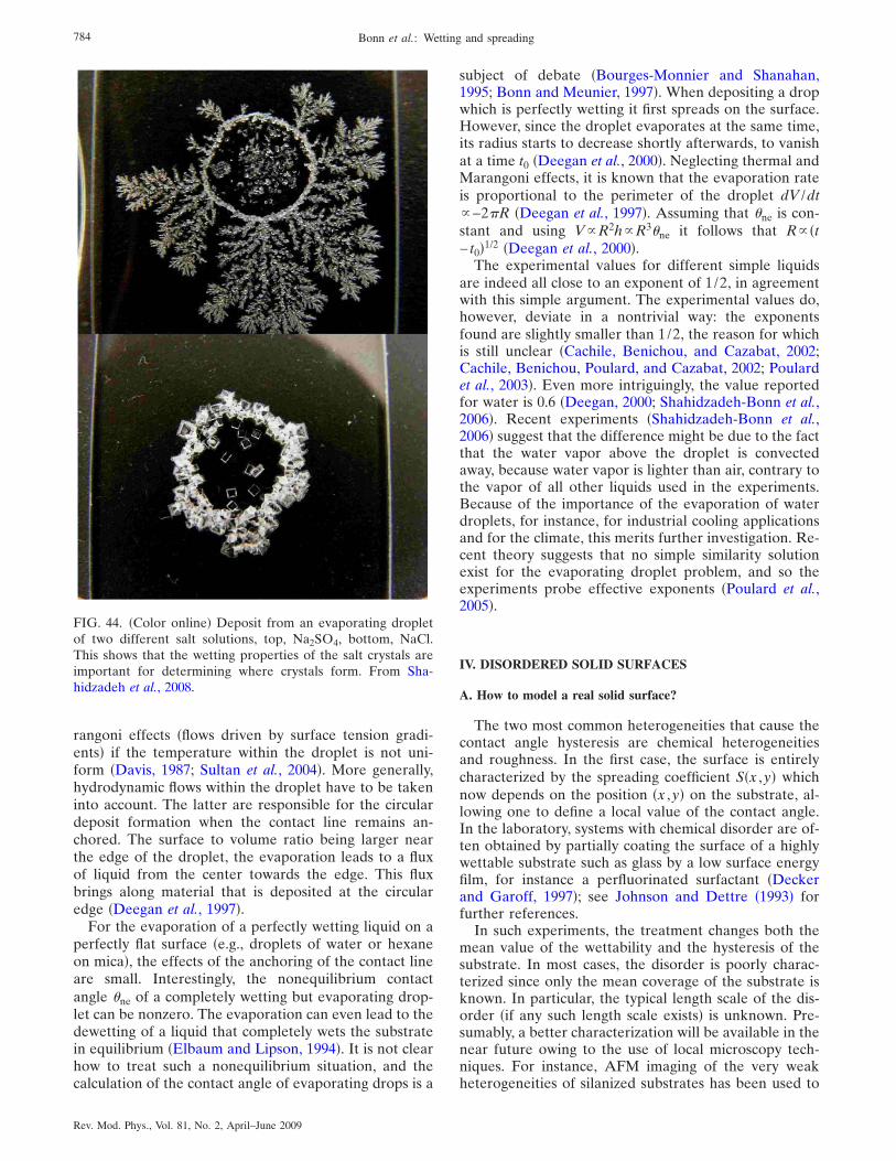
rangoni effects �flows driven by surface tension gradi-ents� if the temperature within the droplet is not uni-form �Davis, 1987; Sultan et al., 2004�. More generally,hydrodynamic flows within the droplet have to be takeninto account. The latter are responsible for the circulardeposit formation when the contact line remains an-chored. The surface to volume ratio being larger nearthe edge of the droplet, the evaporation leads to a fluxof liquid from the center towards the edge. This fluxbrings along material that is deposited at the circularedge �Deegan et al., 1997�.
For the evaporation of a perfectly wetting liquid on aperfectly flat surface �e.g., droplets of water or hexaneon mica�, the effects of the anchoring of the contact lineare small. Interestingly, the nonequilibrium contactangle �ne of a completely wetting but evaporating drop-let can be nonzero. The evaporation can even lead to thedewetting of a liquid that completely wets the substratein equilibrium �Elbaum and Lipson, 1994�. It is not clearhow to treat such a nonequilibrium situation, and thecalculation of the contact angle of evaporating drops is a
subject of debate �Bourges-Monnier and Shanahan,1995; Bonn and Meunier, 1997�. When depositing a dropwhich is perfectly wetting it first spreads on the surface.However, since the droplet evaporates at the same time,its radius starts to decrease shortly afterwards, to vanishat a time t0 �Deegan et al., 2000�. Neglecting thermal andMarangoni effects, it is known that the evaporation rateis proportional to the perimeter of the droplet dV /dt−2R �Deegan et al., 1997�. Assuming that �ne is con-stant and using VR2hR3�ne it follows that R �t− t0�1/2 �Deegan et al., 2000�.
The experimental values for different simple liquidsare indeed all close to an exponent of 1/2, in agreementwith this simple argument. The experimental values do,however, deviate in a nontrivial way: the exponentsfound are slightly smaller than 1/2, the reason for whichis still unclear �Cachile, Benichou, and Cazabat, 2002;Cachile, Benichou, Poulard, and Cazabat, 2002; Poulardet al., 2003�. Even more intriguingly, the value reportedfor water is 0.6 �Deegan, 2000; Shahidzadeh-Bonn et al.,2006�. Recent experiments �Shahidzadeh-Bonn et al.,2006� suggest that the difference might be due to the factthat the water vapor above the droplet is convectedaway, because water vapor is lighter than air, contrary tothe vapor of all other liquids used in the experiments.Because of the importance of the evaporation of waterdroplets, for instance, for industrial cooling applicationsand for the climate, this merits further investigation. Re-cent theory suggests that no simple similarity solutionexist for the evaporating droplet problem, and so theexperiments probe effective exponents �Poulard et al.,2005�.
IV. DISORDERED SOLID SURFACES
A. How to model a real solid surface?
The two most common heterogeneities that cause thecontact angle hysteresis are chemical heterogeneitiesand roughness. In the first case, the surface is entirelycharacterized by the spreading coefficient S�x ,y� whichnow depends on the position �x ,y� on the substrate, al-lowing one to define a local value of the contact angle.In the laboratory, systems with chemical disorder are of-ten obtained by partially coating the surface of a highlywettable substrate such as glass by a low surface energyfilm, for instance a perfluorinated surfactant �Deckerand Garoff, 1997�; see Johnson and Dettre �1993� forfurther references.
In such experiments, the treatment changes both themean value of the wettability and the hysteresis of thesubstrate. In most cases, the disorder is poorly charac-terized since only the mean coverage of the substrate isknown. In particular, the typical length scale of the dis-order �if any such length scale exists� is unknown. Pre-sumably, a better characterization will be available in thenear future owing to the use of local microscopy tech-niques. For instance, AFM imaging of the very weakheterogeneities of silanized substrates has been used to
FIG. 44. �Color online� Deposit from an evaporating dropletof two different salt solutions, top, Na2SO4, bottom, NaCl.This shows that the wetting properties of the salt crystals areimportant for determining where crystals form. From Sha-hidzadeh et al., 2008.
784 Bonn et al.: Wetting and spreading
Rev. Mod. Phys., Vol. 81, No. 2, April–June 2009
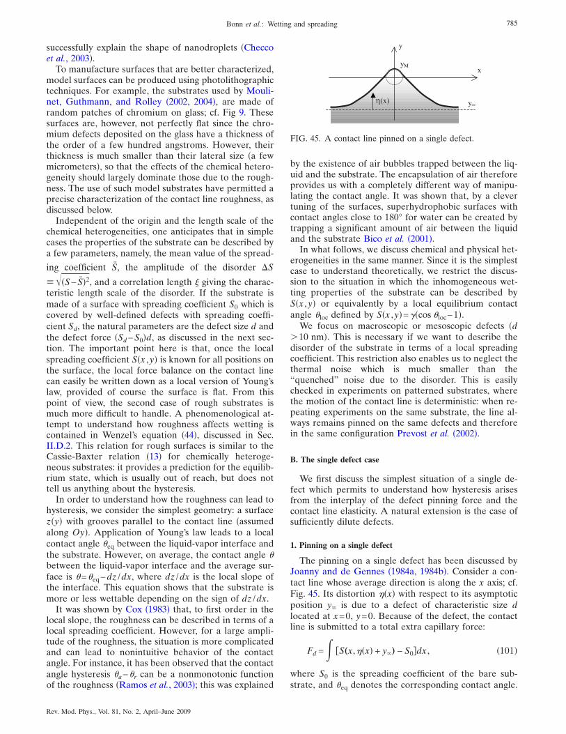
successfully explain the shape of nanodroplets �Checcoet al., 2003�.
To manufacture surfaces that are better characterized,model surfaces can be produced using photolithographictechniques. For example, the substrates used by Mouli-net, Guthmann, and Rolley �2002, 2004�, are made ofrandom patches of chromium on glass; cf. Fig 9. Thesesurfaces are, however, not perfectly flat since the chro-mium defects deposited on the glass have a thickness ofthe order of a few hundred angstroms. However, theirthickness is much smaller than their lateral size �a fewmicrometers�, so that the effects of the chemical hetero-geneity should largely dominate those due to the rough-ness. The use of such model substrates have permitted aprecise characterization of the contact line roughness, asdiscussed below.
Independent of the origin and the length scale of thechemical heterogeneities, one anticipates that in simplecases the properties of the substrate can be described bya few parameters, namely, the mean value of the spread-
ing coefficient S, the amplitude of the disorder �S
���S− S�2, and a correlation length � giving the charac-teristic length scale of the disorder. If the substrate ismade of a surface with spreading coefficient S0 which iscovered by well-defined defects with spreading coeffi-cient Sd, the natural parameters are the defect size d andthe defect force �Sd−S0�d, as discussed in the next sec-tion. The important point here is that, once the localspreading coefficient S�x ,y� is known for all positions onthe surface, the local force balance on the contact linecan easily be written down as a local version of Young’slaw, provided of course the surface is flat. From thispoint of view, the second case of rough substrates ismuch more difficult to handle. A phenomenological at-tempt to understand how roughness affects wetting iscontained in Wenzel’s equation �44�, discussed in Sec.II.D.2. This relation for rough surfaces is similar to theCassie-Baxter relation �13� for chemically heteroge-neous substrates: it provides a prediction for the equilib-rium state, which is usually out of reach, but does nottell us anything about the hysteresis.
In order to understand how the roughness can lead tohysteresis, we consider the simplest geometry: a surfacez�y� with grooves parallel to the contact line �assumedalong Oy�. Application of Young’s law leads to a localcontact angle �eq between the liquid-vapor interface andthe substrate. However, on average, the contact angle �between the liquid-vapor interface and the average sur-face is �=�eq−dz /dx, where dz /dx is the local slope ofthe interface. This equation shows that the substrate ismore or less wettable depending on the sign of dz /dx.
It was shown by Cox �1983� that, to first order in thelocal slope, the roughness can be described in terms of alocal spreading coefficient. However, for a large ampli-tude of the roughness, the situation is more complicatedand can lead to nonintuitive behavior of the contactangle. For instance, it has been observed that the contactangle hysteresis �a−�r can be a nonmonotonic functionof the roughness �Ramos et al., 2003�; this was explained
by the existence of air bubbles trapped between the liq-uid and the substrate. The encapsulation of air thereforeprovides us with a completely different way of manipu-lating the contact angle. It was shown that, by a clevertuning of the surfaces, superhydrophobic surfaces withcontact angles close to 180° for water can be created bytrapping a significant amount of air between the liquidand the substrate Bico et al. �2001�.
In what follows, we discuss chemical and physical het-erogeneities in the same manner. Since it is the simplestcase to understand theoretically, we restrict the discus-sion to the situation in which the inhomogeneous wet-ting properties of the substrate can be described byS�x ,y� or equivalently by a local equilibrium contactangle �loc defined by S�x ,y�=��cos �loc−1�.
We focus on macroscopic or mesoscopic defects �d�10 nm�. This is necessary if we want to describe thedisorder of the substrate in terms of a local spreadingcoefficient. This restriction also enables us to neglect thethermal noise which is much smaller than the“quenched” noise due to the disorder. This is easilychecked in experiments on patterned substrates, wherethe motion of the contact line is deterministic: when re-peating experiments on the same substrate, the line al-ways remains pinned on the same defects and thereforein the same configuration Prevost et al. �2002�.
B. The single defect case
We first discuss the simplest situation of a single de-fect which permits to understand how hysteresis arisesfrom the interplay of the defect pinning force and thecontact line elasticity. A natural extension is the case ofsufficiently dilute defects.
1. Pinning on a single defect
The pinning on a single defect has been discussed byJoanny and de Gennes �1984a, 1984b�. Consider a con-tact line whose average direction is along the x axis; cf.Fig. 45. Its distortion ��x� with respect to its asymptoticposition y� is due to a defect of characteristic size dlocated at x=0, y=0. Because of the defect, the contactline is submitted to a total extra capillary force:
Fd = S„x,��x� + y�… − S0�dx , �101�
where S0 is the spreading coefficient of the bare sub-strate, and �eq denotes the corresponding contact angle.
x
y
η(x) y∞
yM
FIG. 45. A contact line pinned on a single defect.
785Bonn et al.: Wetting and spreading
Rev. Mod. Phys., Vol. 81, No. 2, April–June 2009
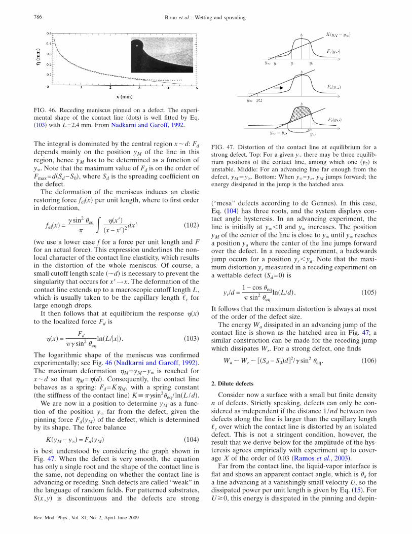
The integral is dominated by the central region x�d: Fddepends mainly on the position yM of the line in thisregion, hence yM has to be determined as a function ofy�. Note that the maximum value of Fd is on the order ofFmax=d�Sd−S0�, where Sd is the spreading coefficient onthe defect.
The deformation of the meniscus induces an elasticrestoring force fel�x� per unit length, where to first orderin deformation,
fel�x� =� sin2 �eq
��x��
�x − x��2dx� �102�
�we use a lower case f for a force per unit length and Ffor an actual force�. This expression underlines the non-local character of the contact line elasticity, which resultsin the distortion of the whole meniscus. Of course, asmall cutoff length scale ��d� is necessary to prevent thesingularity that occurs for x�→x. The deformation of thecontact line extends up to a macroscopic cutoff length L,which is usually taken to be the capillary length �c forlarge enough drops.
It then follows that at equilibrium the response ��x�to the localized force Fd is
��x� =Fd
� sin2 �eqln�L/�x�� . �103�
The logarithmic shape of the meniscus was confirmedexperimentally; see Fig. 46 �Nadkarni and Garoff, 1992�.The maximum deformation �M=yM−y� is reached forx�d so that �M=��d�. Consequently, the contact linebehaves as a spring: Fd=K�M, with a spring constant�the stiffness of the contact line� K��sin2�eq/ ln�L /d�.
We are now in a position to determine yM as a func-tion of the position y� far from the defect, given thepinning force Fd�yM� of the defect, which is determinedby its shape. The force balance
K�yM − y�� = Fd�yM� �104�
is best understood by considering the graph shown inFig. 47. When the defect is very smooth, the equationhas only a single root and the shape of the contact line isthe same, not depending on whether the contact line isadvancing or receding. Such defects are called “weak” inthe language of random fields. For patterned substrates,S�x ,y� is discontinuous and the defects are strong
�“mesa” defects according to de Gennes�. In this case,Eq. �104� has three roots, and the system displays con-tact angle hysteresis. In an advancing experiment, theline is initially at y��0 and y� increases. The positionyM of the center of the line is close to y� until y� reachesa position ya where the center of the line jumps forwardover the defect. In a receding experiment, a backwardsjump occurs for a position yr�ya. Note that the maxi-mum distortion yr measured in a receding experiment ona wettable defect �Sd=0� is
yr/d =1 − cos �eq
sin2 �eqln�L/d� . �105�
It follows that the maximum distortion is always at mostof the order of the defect size.
The energy Wa dissipated in an advancing jump of thecontact line is shown as the hatched area in Fig. 47; asimilar construction can be made for the receding jumpwhich dissipates Wr. For a strong defect, one finds
Wa � Wr � �Sd − S0�d�2/� sin2 �eq. �106�
2. Dilute defects
Consider now a surface with a small but finite densityn of defects. Strictly speaking, defects can only be con-sidered as independent if the distance 1/nd between twodefects along the line is larger than the capillary length�c over which the contact line is distorted by an isolateddefect. This is not a stringent condition, however, theresult that we derive below for the amplitude of the hys-teresis agrees empirically with experiment up to cover-age X of the order of 0.03 �Ramos et al., 2003�.
Far from the contact line, the liquid-vapor interface isflat and shows an apparent contact angle, which is �a fora line advancing at a vanishingly small velocity U, so thedissipated power per unit length is given by Eq. �15�. ForU�0, this energy is dissipated in the pinning and depin-
FIG. 46. Receding meniscus pinned on a defect. The experi-mental shape of the contact line �dots� is well fitted by Eq.�103� with L=2.4 mm. From Nadkarni and Garoff, 1992.
FIG. 47. Distortion of the contact line at equilibrium for astrong defect. Top: For a given y� there may be three equilib-rium positions of the contact line, among which one �y2� isunstable. Middle: For an advancing line far enough from thedefect, yM�y�. Bottom: When y�=ya, yM jumps forward; theenergy dissipated in the jump is the hatched area.
786 Bonn et al.: Wetting and spreading
Rev. Mod. Phys., Vol. 81, No. 2, April–June 2009
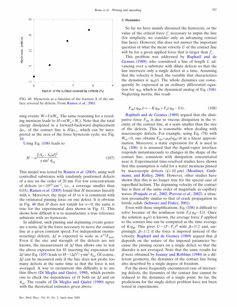
ning events: W=UnWa. The same reasoning for a reced-ing meniscus leads to H=n�Wa+Wr�. Note that the totalenergy dissipated in a forward-backward displacement�y� of the contact line is H�y�, which can be inter-preted as the area of the force hysteresis cycle; see Fig.10.
Using Eq. �106� leads to
H � n�Sd − S0�d�2
� sin2 �eq. �107�
This model was tested by Ramos et al. �2003�, using wellcontrolled substrates with randomly positioned defectsof a size on the order of 20 nm. For low concentrationsof defects �n�1010 cm−2, i.e., a coverage smaller than0.03�, Ramos et al. �2003� found that H increases linearlywith n. Moreover, the slope of H vs n is consistent withthe estimated pinning force on one defect. It is obviousin Fig. 48 that H does not vanish for n=0; the same istrue for the experimental data shown in Fig. 11. Thisshows how difficult it is to manufacture a true referencesubstrate with no hysteresis.
In addition, such pinning and depinning events gener-ate a noise �f in the force necessary to move the contactline at a given constant speed. For independent �nonin-teracting� defects, �f is expected to scale as n1/2Fmax.Even if the size and strength of the defects are notknown, the measurement of �f thus allows one to testthe above expression for H: inserting the expression for�f into Eq. �107� leads to H���f�2 /� sin2 �eq. Of course,�f can be measured only if the line does not probe toomany defects at the same time so that the force is notaveraged. A way to circumvent this difficulty is to usethin fibers �Di Meglio and Quéré, 1990�, which permitsone to check the dependence of H both on �f and on�eq. The results of Di Meglio and Quéré �1990� agreewith the theoretical estimates given above.
3. Dynamics
So far we have mainly discussed the hysteresis, or thevalue of the critical force fc
+ necessary to unpin the line�for simplicity, we consider only an advancing contactline here�. However, this does not answer the importantquestion of what the mean velocity U of the contact linewill be for a given applied force that is larger than fc
+.This problem was addressed by Raphaël and de
Gennes �1989�, who considered a line of length L ad-vancing over a substrate with dilute defects so that theline intersects only a single defect at a time. Assumingthat the velocity is fixed, the variable that characterizesthe dynamics is �M�t�. The whole dynamics can conse-quently be expressed as an ordinary differential equa-tion for �M, which is the dynamical analog of Eq. �104�.Neglecting inertia, this reads
Fdis��M,t� = − K�M + Fd��M − Ut� . �108�
Raphaël and de Gennes �1989� argued that the dissi-pative force Fdis is due to viscous dissipation in the vi-cinity of the contact line, at a scale smaller than the sizeof the defects. This is reasonable when dealing withmacroscopic defects. For example, using Eq. �74� withWm=0, one obtains Fdis=�0d�M /dt in a linear approxi-mation. Moreover, a static expression for K is used inEq. �108�: it is assumed that the liquid-vapor interfaceresponds instantaneously to changes in the shape of thecontact line, consistent with dissipation concentratednear it. Experimental time-resolved studies have shownthat this assumption is valid for a water meniscus pinnedby macroscopic defects ��=10 �m� �Moulinet, Guth-mann, and Rolley, 2004�. However, other studies haveshown that this is no longer true for the special case ofsuperfluid helium. The depinning velocity of the contactline is then of the same order of magnitude as capillarywaves �Poujade et al., 2002; Prevost et al., 2002�, a situa-tion presumably similar to that of crack propagation inbrittle solids �Schwarz and Fisher, 2001�.
Even with these simplifications, Eq. �108� is difficult tosolve because of the nonlinear term Fd��M−Ut�. Oncethe solution �M�t� is known, the average force F appliedto the contact line can be computed as the time averageof K�M. This gives U��F−Fc�� with �=3/2 and, sur-prisingly, �=1/2 if the force is imposed instead of thevelocity. Raphaël and de Gennes �1989� argued that �depends on the nature of the imposed parameter be-cause the pinning occurs on a single defect so that thedisorder is not averaged. Note that the same results for� were obtained by Joanny and Robbins �1990� in a dif-ferent geometry, the dynamics of the contact line beingalso described by a single degree of freedom.
For the more frequently encountered case of interact-ing defects, the dynamics of the contact line cannot bereduced to the dynamics of a single point. So far, thepredictions for the single defect problem have not beentested in experiments.
FIG. 48. Hysteresis as a function of the fraction X of the sur-face covered by defects. From Ramos et al., 2003.
787Bonn et al.: Wetting and spreading
Rev. Mod. Phys., Vol. 81, No. 2, April–June 2009
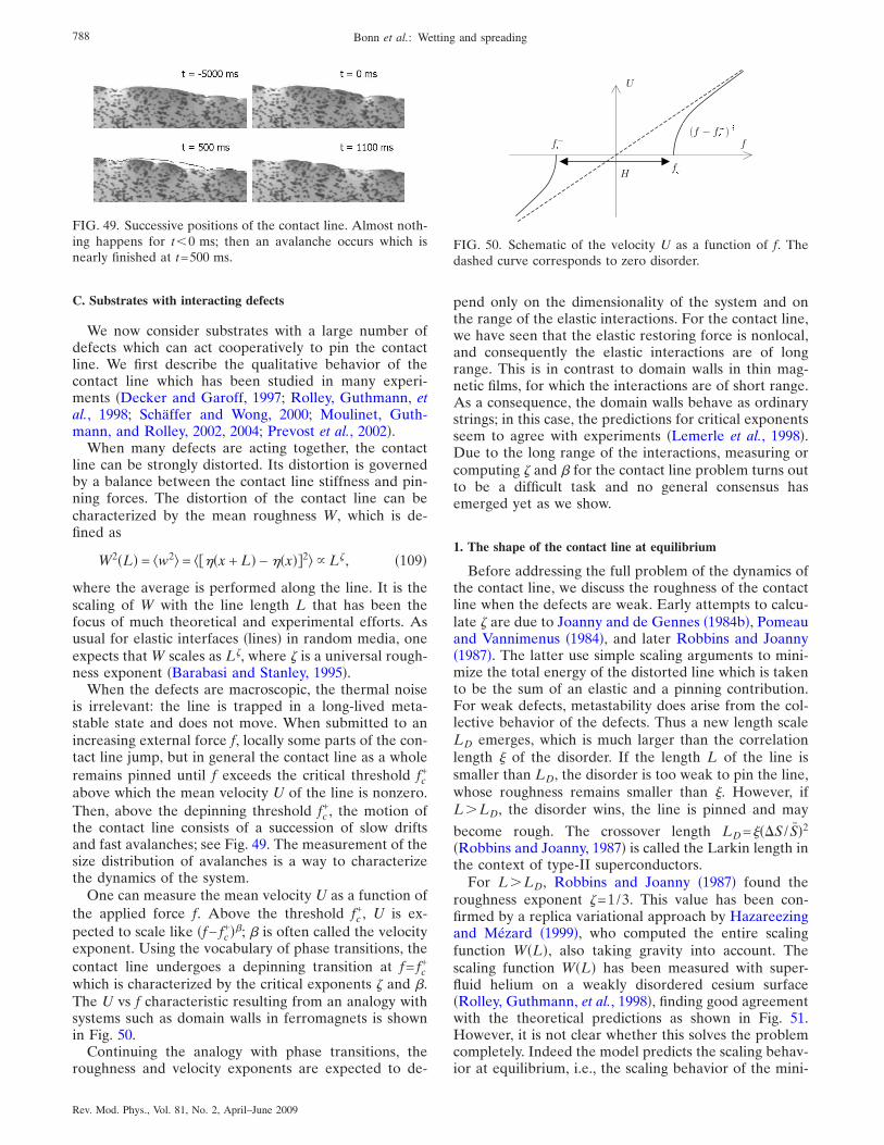
C. Substrates with interacting defects
We now consider substrates with a large number ofdefects which can act cooperatively to pin the contactline. We first describe the qualitative behavior of thecontact line which has been studied in many experi-ments �Decker and Garoff, 1997; Rolley, Guthmann, etal., 1998; Schäffer and Wong, 2000; Moulinet, Guth-mann, and Rolley, 2002, 2004; Prevost et al., 2002�.
When many defects are acting together, the contactline can be strongly distorted. Its distortion is governedby a balance between the contact line stiffness and pin-ning forces. The distortion of the contact line can becharacterized by the mean roughness W, which is de-fined as
W2�L� = �w2� = ���x + L� − ��x��2� L�, �109�
where the average is performed along the line. It is thescaling of W with the line length L that has been thefocus of much theoretical and experimental efforts. Asusual for elastic interfaces �lines� in random media, oneexpects that W scales as L�, where � is a universal rough-ness exponent �Barabasi and Stanley, 1995�.
When the defects are macroscopic, the thermal noiseis irrelevant: the line is trapped in a long-lived meta-stable state and does not move. When submitted to anincreasing external force f, locally some parts of the con-tact line jump, but in general the contact line as a wholeremains pinned until f exceeds the critical threshold fc
+
above which the mean velocity U of the line is nonzero.Then, above the depinning threshold fc
+, the motion ofthe contact line consists of a succession of slow driftsand fast avalanches; see Fig. 49. The measurement of thesize distribution of avalanches is a way to characterizethe dynamics of the system.
One can measure the mean velocity U as a function ofthe applied force f. Above the threshold fc
+, U is ex-pected to scale like �f− fc
+��; � is often called the velocityexponent. Using the vocabulary of phase transitions, thecontact line undergoes a depinning transition at f= fc
+
which is characterized by the critical exponents � and �.The U vs f characteristic resulting from an analogy withsystems such as domain walls in ferromagnets is shownin Fig. 50.
Continuing the analogy with phase transitions, theroughness and velocity exponents are expected to de-
pend only on the dimensionality of the system and onthe range of the elastic interactions. For the contact line,we have seen that the elastic restoring force is nonlocal,and consequently the elastic interactions are of longrange. This is in contrast to domain walls in thin mag-netic films, for which the interactions are of short range.As a consequence, the domain walls behave as ordinarystrings; in this case, the predictions for critical exponentsseem to agree with experiments �Lemerle et al., 1998�.Due to the long range of the interactions, measuring orcomputing � and � for the contact line problem turns outto be a difficult task and no general consensus hasemerged yet as we show.
1. The shape of the contact line at equilibrium
Before addressing the full problem of the dynamics ofthe contact line, we discuss the roughness of the contactline when the defects are weak. Early attempts to calcu-late � are due to Joanny and de Gennes �1984b�, Pomeauand Vannimenus �1984�, and later Robbins and Joanny�1987�. The latter use simple scaling arguments to mini-mize the total energy of the distorted line which is takento be the sum of an elastic and a pinning contribution.For weak defects, metastability does arise from the col-lective behavior of the defects. Thus a new length scaleLD emerges, which is much larger than the correlationlength � of the disorder. If the length L of the line issmaller than LD, the disorder is too weak to pin the line,whose roughness remains smaller than �. However, ifL�LD, the disorder wins, the line is pinned and may
become rough. The crossover length LD=���S / S�2
�Robbins and Joanny, 1987� is called the Larkin length inthe context of type-II superconductors.
For L�LD, Robbins and Joanny �1987� found theroughness exponent �=1/3. This value has been con-firmed by a replica variational approach by Hazareezingand Mézard �1999�, who computed the entire scalingfunction W�L�, also taking gravity into account. Thescaling function W�L� has been measured with super-fluid helium on a weakly disordered cesium surface�Rolley, Guthmann, et al., 1998�, finding good agreementwith the theoretical predictions as shown in Fig. 51.However, it is not clear whether this solves the problemcompletely. Indeed the model predicts the scaling behav-ior at equilibrium, i.e., the scaling behavior of the mini-
FIG. 49. Successive positions of the contact line. Almost noth-ing happens for t�0 ms; then an avalanche occurs which isnearly finished at t=500 ms.
FIG. 50. Schematic of the velocity U as a function of f. Thedashed curve corresponds to zero disorder.
788 Bonn et al.: Wetting and spreading
Rev. Mod. Phys., Vol. 81, No. 2, April–June 2009
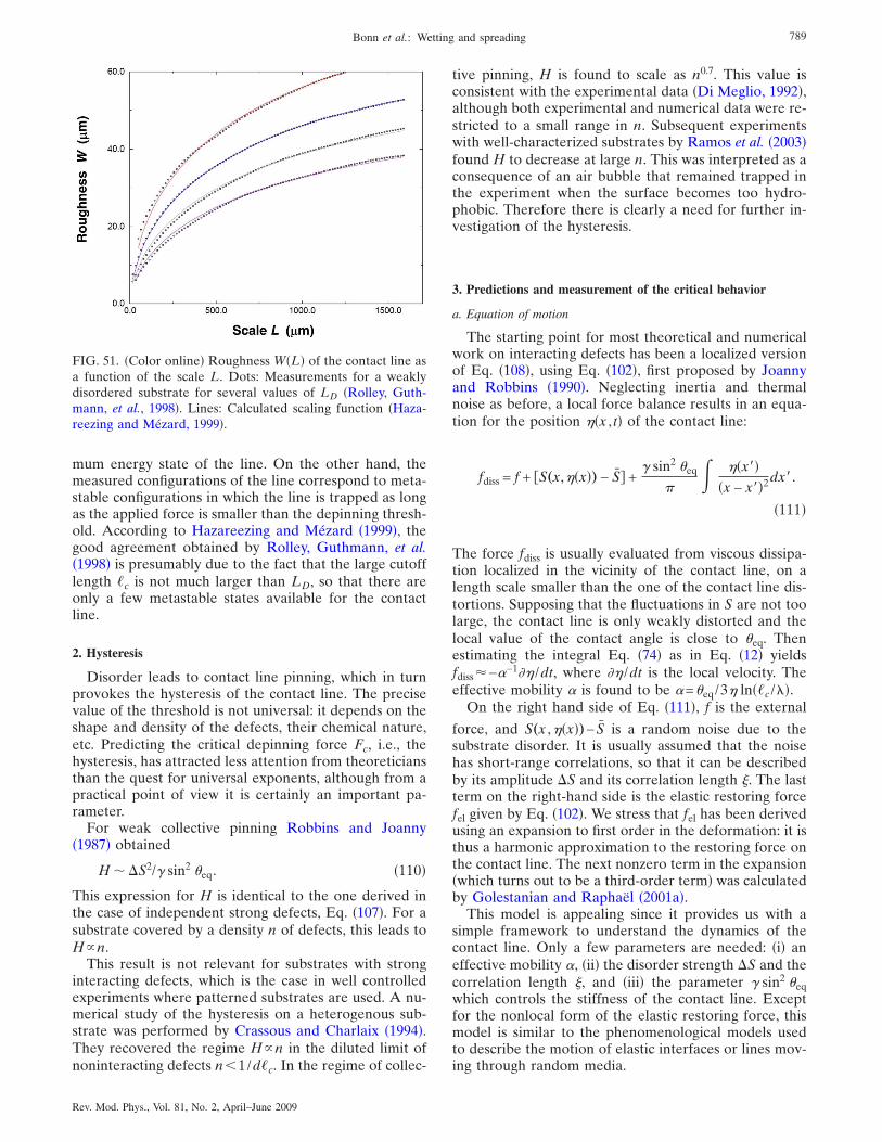
mum energy state of the line. On the other hand, themeasured configurations of the line correspond to meta-stable configurations in which the line is trapped as longas the applied force is smaller than the depinning thresh-old. According to Hazareezing and Mézard �1999�, thegood agreement obtained by Rolley, Guthmann, et al.�1998� is presumably due to the fact that the large cutofflength �c is not much larger than LD, so that there areonly a few metastable states available for the contactline.
2. Hysteresis
Disorder leads to contact line pinning, which in turnprovokes the hysteresis of the contact line. The precisevalue of the threshold is not universal: it depends on theshape and density of the defects, their chemical nature,etc. Predicting the critical depinning force Fc, i.e., thehysteresis, has attracted less attention from theoreticiansthan the quest for universal exponents, although from apractical point of view it is certainly an important pa-rameter.
For weak collective pinning Robbins and Joanny�1987� obtained
H � �S2/� sin2 �eq. �110�
This expression for H is identical to the one derived inthe case of independent strong defects, Eq. �107�. For asubstrate covered by a density n of defects, this leads toHn.
This result is not relevant for substrates with stronginteracting defects, which is the case in well controlledexperiments where patterned substrates are used. A nu-merical study of the hysteresis on a heterogenous sub-strate was performed by Crassous and Charlaix �1994�.They recovered the regime Hn in the diluted limit ofnoninteracting defects n�1/d�c. In the regime of collec-
tive pinning, H is found to scale as n0.7. This value isconsistent with the experimental data �Di Meglio, 1992�,although both experimental and numerical data were re-stricted to a small range in n. Subsequent experimentswith well-characterized substrates by Ramos et al. �2003�found H to decrease at large n. This was interpreted as aconsequence of an air bubble that remained trapped inthe experiment when the surface becomes too hydro-phobic. Therefore there is clearly a need for further in-vestigation of the hysteresis.
3. Predictions and measurement of the critical behavior
a. Equation of motion
The starting point for most theoretical and numericalwork on interacting defects has been a localized versionof Eq. �108�, using Eq. �102�, first proposed by Joannyand Robbins �1990�. Neglecting inertia and thermalnoise as before, a local force balance results in an equa-tion for the position ��x , t� of the contact line:
fdiss = f + S„x,��x�… − S� +� sin2 �eq
��x��
�x − x��2dx�.
�111�
The force fdiss is usually evaluated from viscous dissipa-tion localized in the vicinity of the contact line, on alength scale smaller than the one of the contact line dis-tortions. Supposing that the fluctuations in S are not toolarge, the contact line is only weakly distorted and thelocal value of the contact angle is close to �eq. Thenestimating the integral Eq. �74� as in Eq. �12� yieldsfdiss�−�−1�� /dt, where �� /dt is the local velocity. Theeffective mobility � is found to be �=�eq/3� ln��c /"�.
On the right hand side of Eq. �111�, f is the external
force, and S„x ,��x�…− S is a random noise due to thesubstrate disorder. It is usually assumed that the noisehas short-range correlations, so that it can be describedby its amplitude �S and its correlation length �. The lastterm on the right-hand side is the elastic restoring forcefel given by Eq. �102�. We stress that fel has been derivedusing an expansion to first order in the deformation: it isthus a harmonic approximation to the restoring force onthe contact line. The next nonzero term in the expansion�which turns out to be a third-order term� was calculatedby Golestanian and Raphaël �2001a�.
This model is appealing since it provides us with asimple framework to understand the dynamics of thecontact line. Only a few parameters are needed: �i� aneffective mobility �, �ii� the disorder strength �S and thecorrelation length �, and �iii� the parameter � sin2 �eqwhich controls the stiffness of the contact line. Exceptfor the nonlocal form of the elastic restoring force, thismodel is similar to the phenomenological models usedto describe the motion of elastic interfaces or lines mov-ing through random media.
FIG. 51. �Color online� Roughness W�L� of the contact line asa function of the scale L. Dots: Measurements for a weaklydisordered substrate for several values of LD �Rolley, Guth-mann, et al., 1998�. Lines: Calculated scaling function �Haza-reezing and Mézard, 1999�.
789Bonn et al.: Wetting and spreading
Rev. Mod. Phys., Vol. 81, No. 2, April–June 2009
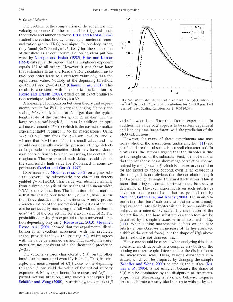
b. Critical behavior
The problem of the computation of the roughness andvelocity exponents for the contact line triggered muchtheoretical and numerical work. Ertas and Kardar �1994�studied the contact line dynamics by a functional renor-malization group �FRG� technique. To one-loop order,they found �=7/9 and �=1/3, i.e., � has the same valueat threshold as at equilibrium. Following ideas put for-ward by Narayan and Fisher �1992�, Ertas and Kardar�1994� subsequently argued that the roughness exponentequals 1 /3 to all orders. However, it was shown laterthat extending Ertas and Kardar’s RG calculation up totwo-loop order leads to a different value of � than theequilibrium value. Notably, at the depinning threshold�=0.5±0.1 and ��0.4±0.2 �Chauve et al., 2001�. Thisresult is consistent with a numerical calculation byRosso and Krauth �2002�, based on an exact enumera-tion technique, which yields �=0.39.
A meaningful comparison between theory and experi-mental results for W�L� is very challenging. Namely, thescaling WL� only holds for L larger than the typicallength scale of the disorder �, and L smaller than thelarge-scale cutoff length �c�1 mm. In addition, an opti-cal measurement of W�L� �which is the easiest to realizeexperimentally� requires � to be macroscopic. UsingW /���L /���, one finds for �=1 �m, �=0.39, and L=1 mm that W=15 �m. This is a small value, and oneshould consequently avoid the presence of large defectsor large-scale heterogeneities which may have a domi-nant contribution to W when measuring the contact lineroughness. The presence of such defects could explainthe surprisingly high value for � obtained in some ex-periments �Decker and Garoff, 1997�.
Experiments by Moulinet et al. �2002� on a glass sub-strate covered by micrometric size chromium defectsyielded �=0.51±0.03. This value was obtained initiallyfrom a simple analysis of the scaling of the mean widthW�L� of the contact line. The limitation of that methodis that the scaling only holds for ��L��c, which is lessthan three decades in the experiments. A more precisecharacterization of the geometrical properties of the linecan be achieved by measuring the full width distribution#�w2 /W2� of the contact line for a given value of L. Theprobability density # is expected to be a universal func-tion depending only on � �Rosso et al., 2003�. Moulinet,Rosso, et al. �2004� showed that the experimental distri-bution is in excellent agreement with the predictedshape, provided that �=0.50 �see Fig. 52�, which agreeswith the value determined earlier. Thus careful measure-ments are not consistent with the theoretical prediction�=0.39.
The velocity vs force characteristic U�f�, on the otherhand, can be measured even if � is small. Thus, in prin-ciple, any measurement of U�f� close to the depinningthreshold fc can yield the value of the critical velocityexponent �. Many experiments have measured U�f� in apartial wetting situation, using various techniques seeSchäffer and Wong �2000��. Surprisingly, the exponent �
varies between 1 and 5 for the different experiments. Inaddition, the value of � appears to be system dependentand is in any case inconsistent with the prediction of theFRG calculations.
However, for many of these experiments one mayworry whether the assumptions underlying Eq. �111� arejustified, since the substrate is not well characterized. Inmost cases, the authors argued that the disorder is dueto the roughness of the substrate. First, it is not obviousthat the roughness has a short-range correlation charac-terized by a single scale �, which is a necessary conditionfor the model to apply. Second, even if the disorder isshort range, it is not obvious that the correlation length� is large enough to neglect thermal fluctuations. Thus itseems that using patterned substrates is the best way todetermine �. However, experiments on such substrateshave not been conclusive either, as pointed out byMoulinet, Guthmann, and Rolley �2004�. The main rea-son is that the “bare” substrate without patterns alreadydisplays some intrinsic hysteresis and is presumably dis-ordered at a microscopic scale. The dissipation of thecontact line on the bare substrate can therefore not bedescribed by a simple viscous term as assumed in Eq.�111�. When adding macroscopic defects on the baresubstrate, one observes an increase of the hysteresis �ora shift of the critical force�, but the shape of U�f� abovethe threshold is not changed much.
Hence one should be careful when analyzing this char-acteristic, which depends in a complex way both on thepinning on macroscopic defects and on the dissipation atthe microscopic scale. Using various disordered sub-strates, which can be prepared by changing the sample�Schäffer and Wong, 2000� or etching the surface �Ku-mar et al., 1995�, is not sufficient because the shape ofU�f� can be dominated by the dissipation at the micro-scopic scale. Measuring true critical behavior requiresfirst to elaborate a nearly ideal substrate without hyster-
FIG. 52. Width distribution of a contact line #�z�, where z=w2 /W2. Symbols: Measured distribution for L=500 �m. Full�dashed� line: Scaling function for �=0.50 �0.39�.
790 Bonn et al.: Wetting and spreading
Rev. Mod. Phys., Vol. 81, No. 2, April–June 2009
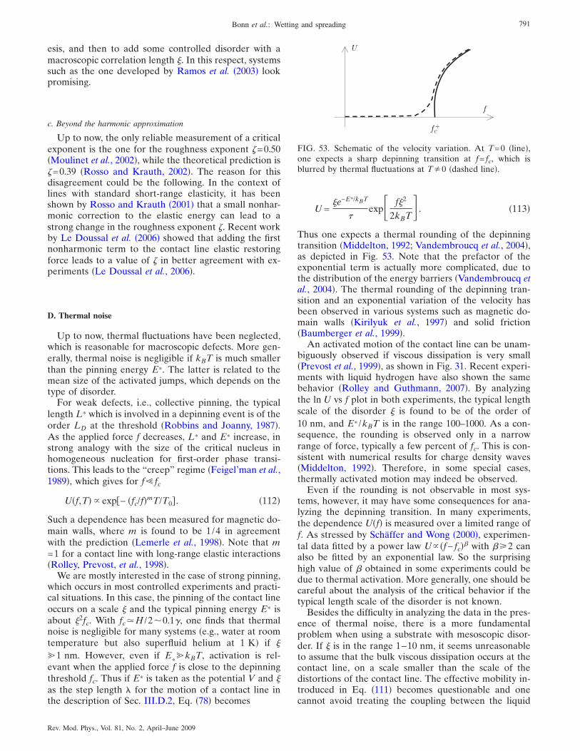
esis, and then to add some controlled disorder with amacroscopic correlation length �. In this respect, systemssuch as the one developed by Ramos et al. �2003� lookpromising.
c. Beyond the harmonic approximation
Up to now, the only reliable measurement of a criticalexponent is the one for the roughness exponent �=0.50�Moulinet et al., 2002�, while the theoretical prediction is�=0.39 �Rosso and Krauth, 2002�. The reason for thisdisagreement could be the following. In the context oflines with standard short-range elasticity, it has beenshown by Rosso and Krauth �2001� that a small nonhar-monic correction to the elastic energy can lead to astrong change in the roughness exponent �. Recent workby Le Doussal et al. �2006� showed that adding the firstnonharmonic term to the contact line elastic restoringforce leads to a value of � in better agreement with ex-periments �Le Doussal et al., 2006�.
D. Thermal noise
Up to now, thermal fluctuations have been neglected,which is reasonable for macroscopic defects. More gen-erally, thermal noise is negligible if kBT is much smallerthan the pinning energy E*. The latter is related to themean size of the activated jumps, which depends on thetype of disorder.
For weak defects, i.e., collective pinning, the typicallength L* which is involved in a depinning event is of theorder LD at the threshold �Robbins and Joanny, 1987�.As the applied force f decreases, L* and E* increase, instrong analogy with the size of the critical nucleus inhomogeneous nucleation for first-order phase transi-tions. This leads to the “creep” regime �Feigel’man et al.,1989�, which gives for f fc
U�f,T� exp− �fc/f�mT/T0� . �112�
Such a dependence has been measured for magnetic do-main walls, where m is found to be 1/4 in agreementwith the prediction �Lemerle et al., 1998�. Note that m=1 for a contact line with long-range elastic interactions�Rolley, Prevost, et al., 1998�.
We are mostly interested in the case of strong pinning,which occurs in most controlled experiments and practi-cal situations. In this case, the pinning of the contact lineoccurs on a scale � and the typical pinning energy E* isabout �2fc. With fc�H /2�0.1�, one finds that thermalnoise is negligible for many systems �e.g., water at roomtemperature but also superfluid helium at 1 K� if �
%1 nm. However, even if E*%kBT, activation is rel-
evant when the applied force f is close to the depinningthreshold fc. Thus if E* is taken as the potential V and �as the step length " for the motion of a contact line inthe description of Sec. III.D.2, Eq. �78� becomes
U =�e−E*/kBT
�exp� f�2
2kBT . �113�
Thus one expects a thermal rounding of the depinningtransition �Middelton, 1992; Vandembroucq et al., 2004�,as depicted in Fig. 53. Note that the prefactor of theexponential term is actually more complicated, due tothe distribution of the energy barriers �Vandembroucq etal., 2004�. The thermal rounding of the depinning tran-sition and an exponential variation of the velocity hasbeen observed in various systems such as magnetic do-main walls �Kirilyuk et al., 1997� and solid friction�Baumberger et al., 1999�.
An activated motion of the contact line can be unam-biguously observed if viscous dissipation is very small�Prevost et al., 1999�, as shown in Fig. 31. Recent experi-ments with liquid hydrogen have also shown the samebehavior �Rolley and Guthmann, 2007�. By analyzingthe ln U vs f plot in both experiments, the typical lengthscale of the disorder � is found to be of the order of10 nm, and E* /kBT is in the range 100–1000. As a con-sequence, the rounding is observed only in a narrowrange of force, typically a few percent of fc. This is con-sistent with numerical results for charge density waves�Middelton, 1992�. Therefore, in some special cases,thermally activated motion may indeed be observed.
Even if the rounding is not observable in most sys-tems, however, it may have some consequences for ana-lyzing the depinning transition. In many experiments,the dependence U�f� is measured over a limited range off. As stressed by Schäffer and Wong �2000�, experimen-tal data fitted by a power law U �f− fc�� with ��2 canalso be fitted by an exponential law. So the surprisinghigh value of � obtained in some experiments could bedue to thermal activation. More generally, one should becareful about the analysis of the critical behavior if thetypical length scale of the disorder is not known.
Besides the difficulty in analyzing the data in the pres-ence of thermal noise, there is a more fundamentalproblem when using a substrate with mesoscopic disor-der. If � is in the range 1–10 nm, it seems unreasonableto assume that the bulk viscous dissipation occurs at thecontact line, on a scale smaller than the scale of thedistortions of the contact line. The effective mobility in-troduced in Eq. �111� becomes questionable and onecannot avoid treating the coupling between the liquid
FIG. 53. Schematic of the velocity variation. At T=0 �line�,one expects a sharp depinning transition at f= fc, which isblurred by thermal fluctuations at T�0 �dashed line�.
791Bonn et al.: Wetting and spreading
Rev. Mod. Phys., Vol. 81, No. 2, April–June 2009
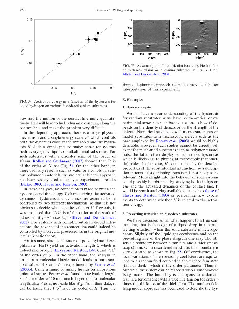
flow and the motion of the contact line more quantita-tively. This will lead to hydrodynamic coupling along thecontact line, and make the problem very difficult.
In the depinning approach, there is a single physicalmechanism and a single energy scale E* which controlsboth the dynamics close to the threshold and the hyster-esis H. Such a simple picture makes sense for systemssuch as cryogenic liquids on alkali-metal substrates. Forsuch substrates with a disorder scale of the order of10 nm, Rolley and Guthmann �2007� showed that E* isof the order of H; see Fig. 54. On the other hand, inmore ordinary systems such as water or alcohols on vari-ous polymeric materials, the molecular kinetic approachhas been widely used to analyze experimental results�Blake, 1993; Hayes and Ralston, 1993�.
In these analyses, no connection is made between thehysteresis and the energy V characterizing the activateddynamics. Hysteresis and dynamics are assumed to becontrolled by two different mechanisms, so that it is notobvious to decide what sets the value of V. Recently, itwas proposed that V /"2 is of the order of the work ofadhesion WA=��1+cos �eq� �Blake and De Coninck,2002�. For systems with complex substrate-liquid inter-actions, the advance of the contact line could indeed becontrolled by molecular processes, as in the original mo-lecular kinetic theory.
For instance, studies of water on polyethylene there-phthalate �PET� yield an activation length " which isindeed microscopic �Hayes and Ralston, 1993�, and V /"2
of the order of �. On the other hand, the analysis interms of a molecular-kinetic model leads to unreason-able values of " and V in experiments by Petrov et al.�2003b�. Using a range of simple liquids on amorphousteflon substrates Petrov et al. found an activation length" of the order of 10 nm, much larger than a molecularlength; also V does not scale like WA. From their data, itcan be found that V /"2 is of the order of H. Thus the
simple depinning approach seems to provide a betterinterpretation of this experiment.
E. Hot topics
1. Hysteresis again
We still have a poor understanding of the hysteresisfor random substrates as we have no theoretical or ex-perimental answer to such basic questions as how H de-pends on the density of defects or on the strength of thedefects. Numerical studies as well as measurements onmodel substrates with macroscopic defects such as theones employed by Ramos et al. �2003� would be highlydesirable. However, such studies cannot be directly rel-evant for much-used substrates such as polymeric mate-rials; the latter often display some intrinsic hysteresiswhich is likely due to pinning at microscopic �nanomet-ric� scales. In this case, H is controlled by the detailedproperties of the substrate-fluid interaction, so a descrip-tion in terms of a depinning transition is not likely to berelevant. More insight into the behavior of such systemscould possibly be obtained by studying both the hyster-esis and the activated dynamics of the contact line. Itwould be worth analyzing available data such as those ofHayes and Ralston �1993� or performing new experi-ments to determine whether H is related to the activa-tion energy.
2. Prewetting transition on disordered substrates
We have discussed so far what happens to a true con-tact line, that is the edge of a liquid drop in a partialwetting situation, when the solid substrate is heteroge-neous. Slightly off the liquid-gas coexistence and on theprewetting line of the phase diagram one may also ob-serve a boundary between a thin film and a thick �meso-scopic� film. On a disordered substrate, this boundary isvery distorted as shown in Fig. 55. Off coexistence, thelocal variations of the spreading coefficient are equiva-lent to a random field coupled to the surface film state�thin or thick�, which is the order parameter. Thus, inprinciple, the system can be mapped onto a random-fieldIsing model. The boundary is analogous to a domainwall in a ferromagnet with a true line tension �of order �times the thickness of the thick film�. The random-fieldIsing model approach has been used to describe the hys-
0
0.05
0.1
0.15
0 0.05 0.1 0.15 0.2
H/�
E*/�
FIG. 54. Activation energy as a function of the hysteresis forliquid hydrogen on various disordered cesium substrates.
FIG. 55. Advancing thin film/thick film boundary. Helium filmof thickness 50 nm on a cesium substrate at 1.87 K. FromMüller and Dupont-Roc, 2001.
792 Bonn et al.: Wetting and spreading
Rev. Mod. Phys., Vol. 81, No. 2, April–June 2009
teresis of the prewetting transition �Blossey et al., 1998�on solid substrates as well as the activated motion of theboundary �Müller and Dupont-Roc, 2001�. However, ex-perimental results are still sparse in this field.
ACKNOWLEDGMENTS
LPS de l’ENS is UMR 8550 of the CNRS, associatedwith Universities Paris 6 and 7. We would like to thankthe numerous colleagues with whom we intergaded onthe subjects treated here, for many helpful discussionsand criticisms. J.I. would like to acknowledge FWOGrant No. G.0115.06 and KULeuven Grant No. GOA/2004/02.
REFERENCES
Aarts, D. G. A. L., 2005, “The capillary length in a fluid-fluiddemixed colloid-polymer mixture,” J. Phys. Chem. B 109,7407.
Aarts, D. G. A. L., R. P. A. Dullens, H. N. W. Lekkerkerker,D. Bonn, and R. van Roij, 2004, “Interfacial tension and wet-ting in colloid-polymer mixtures,” J. Chem. Phys. 120, 1973.
Aarts, D. G. A. L., and H. N. W. Lekkerkerker, 2004, “Confo-cal scanning laser microscopy on fluid-fluid demixing colloid-polymer mixtures,” J. Phys.: Condens. Matter 16, S4231.
Aarts, D. G. A. L., M. Schmidt, and H. N. W. Lekkerkerker,2004, “Direct visual observation of thermal capillary waves,”Science 304, 847.
Aarts, D. G. A. L., J. H. van der Wiel, and H. N. W. Lek-kerkerker, 2003, “Interfacial dynamics and the static profilenear a single wall in a model colloid-polymer mixture,” J.Phys.: Condens. Matter 15, S245.
Abkarian, M., J. Nunes, and H. A. Stone, 2004, “Colliodalcrystallization and banding in a cylindrical geometry,” J. Am.Chem. Soc. 126, 5978.
Abraham, D., A. Parry, and A. Wood, 2002, “Drumheadmodel of 2D wetting, filling and wedge covariance,” Euro-phys. Lett. 60, 106.
Abraham, D. B., R. Cuerno, and E. Moro, 2002, “Microscopicmodel for thin film spreading,” Phys. Rev. Lett. 88, 206101.
Abraham, D. B., and A. Maciolek, 2002, “Filling transition:Exact results for Ising corners,” Phys. Rev. Lett. 89, 286101.
Abraham, D. B., V. Mustonen, and A. Wood, 2003, “Triangularlattice solution for filling in a wedge,” Europhys. Lett. 63,408.
Abramowitz, M., and I. A. Stegun, 1968, Handbook of Math-ematical Functions �Dover, New York�.
Ala-Nissila, T., S. Herminghaus, T. Hjelt, and P. Leiderer, 1996,“Diffusive spreading of chainlike molecules on surfaces,”Phys. Rev. Lett. 76, 4003.
Alava, M., M. Dube, and M. Rost, 2004, “Imbibition in disor-dered media,” Adv. Phys. 53, 83.
Albano, E., A. D. Virgiliis, M. Müller, and K. Binder, 2003,“Corner wetting in the two-dimensional Ising model: MonteCarlo results,” J. Phys.: Condens. Matter 15, 333.
Albrecht, A. O., and P. Leiderer, 1992, “Two-dimensional liq-uid polymer diffusion: Experiment and simulation,” Phys.Rev. Lett. 68, 3192.
Allen, M., and D. Tildesley, 1987, Computer Simulations ofLiquids �Clarendon, New York�.
Ansini, L., and L. Giacomelli, 2002, “Shear-thinning liquid
films: Macroscopic and asymptotic behaviour by quasi-self-similar solutions,” Nonlinearity 15, 2147.
Arscott, S., M. Gaudet, M. Brinkmann, A. Ashcroft, and R.Blossey, 2006, “Capillary filling of miniaturized sources forelectrospray mass spectrometry,” J. Phys.: Condens. Matter18, S677.
Asakura, S., and F. Oosawa, 1954, “On interaction betweentwo bodies immersed in a solution of macromolecules,” J.Chem. Phys. 22, 1255.
Asakura, S., and F. Oosawa, 1958, “Interaction between par-ticles suspended in solutions of macromolecules,” J. Polym.Sci. 33, 183.
Aussere, D., A. M. Picard, and L. Léger, 1986, “Existence androle of the precursor film in the spreading of polymer liq-uids,” Phys. Rev. Lett. 57, 2671.
Balibar, S., and S. Ishiguro, 2005, “Critical Casimir forces andanomalous wetting,” Pramana, J. Phys. 64, 743.
Barabasi, A.-L., and H. E. Stanley, 1995, Fractal Concepts inSurface Growth �Cambridge University Press, Cambridge,England�.
Bartolo, D., F. Bouamrirene, E. A. Buguin, P. Silberzan, and S.Moulinet, 2006, “Bouncing or sticky droplets: Impalementtransitions on superhydrophobic micropatterned surfaces,”Europhys. Lett. 74, 299.
Bascom, W. D., R. Cottington, and C. Singleterry, 1964, inContact Angle, Wettability, and Adhesion, edited by F. M.Fowkes �American Chemical Society, Washington, D.C.�, p.355.
Bauer, C., and S. Dietrich, 1999a, “Quantitative study of later-ally inhomogeneous wetting,” Eur. Phys. J. B 10, 767.
Bauer, C., and S. Dietrich, 1999b, “Wetting films on chemicallyheterogeneous substrates,” Phys. Rev. E 60, 6919.
Bauer, C., and S. Dietrich, 2000, “Phase diagram for morpho-logical transitions of wetting films on chemically structuredsubstrates,” Phys. Rev. E 61, 1664.
Bauer, C., S. Dietrich, and A. Parry, 1999, “Morphologicalphase transitions of thin fluid films on chemically structuredsubstrates,” Europhys. Lett. 47, 474.
Baumberger, T., P. Berthoud, and C. Caroli, 1999, “Physicalanalysis of the state- and rate-dependent friction law. II. Dy-namic friction,” Phys. Rev. B 60, 3928.
Bazhlekov, I. B., and A. K. Chesters, 1996, “Numerical inves-tigation of the dynamic influence of the contact line region onthe macroscopic meniscus shape,” J. Fluid Mech. 329, 137.
Beaglehole, D., 1989, “Profiles of the precursor of spreadingdrops of siloxane oil on glass, fused silica, and mica,” J. Phys.Chem. 93, 893.
Bechinger, C., D. Rudhardt, P. Leiderer, R. Roth, and S.Dietrich, 1999, “Understanding depletion forces beyond en-tropy,” Phys. Rev. Lett. 83, 3960.
Becker, J., and G. Grün, 2005, “The thin-film equation: Recentadvances and some new perspectives,” J. Phys.: Condens.Matter 17, S291.
Becker, J., G. Grün, R. Seemann, H. Mantz, K. Jacobs, K. R.Mecke, and R. Blossey, 2003, “Complex dewetting scenarioscaptured by thin-film models,” Nature Mater. 2, 59.
Bekink, S., S. Karaborni, G. Verbist, and K. Esselink, 1996,“Simulating the spreading of a drop in the terraced wettingregime,” Phys. Rev. Lett. 76, 3766.
Benney, D. J., 1966, “Long waves on liquid films,” J. Math.Phys. �Cambridge, Mass.� 45, 150.
Benney, D. J., and W. J. Timson, 1980, “The rolling motion ofa viscous fluid on and off a rigid surface,” Stud. Appl. Math.
793Bonn et al.: Wetting and spreading
Rev. Mod. Phys., Vol. 81, No. 2, April–June 2009
63, 93.Benzi, R., L. Biferale, M. Sbragaglia, S. Succi, and F. Toschi,
2006, “Mesoscopic modeling of a two-phase flow in the pres-ence of boundaries: The contact angle,” Phys. Rev. E 74,021509.
Berg, J. C., 1993, Ed., Wettability �Dekker, New York�.Bergeron, V., D. Bonn, J.-Y. Martin, and L. Vovelle, 2000,
“Controlling droplet deposition with polymer additives,” Na-ture �London� 405, 772.
Bertozzi, A. L., and M. P. Brenner, 1997, “Linear stability andtransient growth in driven contact lines,” Phys. Fluids 9, 530.
Bertozzi, A. L., A. Munch, X. Fanton, and A.-M. Cazabat,1998, “Contact line stability and “undercompressive shocks”in a driven thin film flow,” Phys. Rev. Lett. 81, 5169.
Bertozzi, A. L., A. Munch, and M. Shearer, 1999, “Undercom-pressive shocks in thin film flows,” Physica D 134, 431.
Bertrand, E., D. Bonn, D. Broseta, H. Dobbs, J. O. Indekeu, J.Meunier, K. Ragil, and N. Shahidzadeh, 2002, “Wetting ofalkanes on water,” J. Pet. Sci. Eng. 33, 217.
Bertrand, E., D. Bonn, D. Broseta, N. Shahidzadeh, K. Ragil,H. Dobbs, J. O. Indekeu, and J. Meunier, 2002, “Wetting ofalkanes on water,” J. Pet. Sci. Eng. 33, 217.
Bertrand, E., D. Bonn, H. Kellay, B. Binks, and J. Meunier,2001, “Fluctuation effects on wetting films,” Europhys. Lett.55, 827.
Betelu, S. I., and M. A. Fontelos, 2003, “Capillarity drivenspreading of power-law fluids,” Appl. Math. Lett. 16, 1315.
Betelu, S. I., and M. A. Fontelos, 2004, “Capillarity drivenspreading of circular drops of shear-thinning fluid,” Math.Comput. Modell. 40, 729.
Biance, A.-L., C. Clanet, and D. Quéré, 2004, “First steps ofthe spreading of a liquid droplet,” Phys. Rev. E 69, 016301.
Biben, T., P. Bladon, and D. Frenkel, 1996, “Depletion effectsin binary hard-sphere fluids,” J. Phys.: Condens. Matter 8,10799.
Bico, J., C. Marzolin, and D. Quéré, 1999, “Pearl drops,” Eu-rophys. Lett. 47, 220.
Bico, J., C. Tordeux, and D. Quéré, 2001, “Rough wetting,”Europhys. Lett. 55, 214.
Bieker, T., and S. Dietrich, 1998, “Wetting of curved surfaces,”Physica A 252, 85.
Bienia, M., M. Vallade, C. Quilliet, and F. Mugele, 2006,“Electrical-field-induced curvature increase on a drop of con-ducting liquid,” Europhys. Lett. 74, 103.
Biferale, L., R. Benzi, M. Sbragaglia, S. Succi, and F. Toschi,2007, “Wetting/dewetting transition of two-phase flows innano-corrugated channels,” J. Comput.-Aided Mater. Des.14, 447.
Binder, K., and D. P. Landau, 1988, “Wetting layering in thenearest-neighbor simple-cubic Ising lattice—A Monte-Carloinvestigation,” Phys. Rev. B 37, 1745.
Binder, K., D. P. Landau, and D. M. Kroll, 1986, “Critical wet-ting with short-range forces—Is mean-filed theory valid?,”Phys. Rev. Lett. 56, 2272.
Binder, K., D. P. Landau, and S. Wansleben, 1989, “Wettingtransitions near the bulk critical point—Monte-Carlo simula-tions for the Ising model,” Phys. Rev. B 40, 6971.
Bischof, J., D. Scherer, S. Herminghaus, and P. Leiderer, 1996,“Dewetting modes of thin metallic films: Nucleation of holesand spinodal dewetting,” Phys. Rev. Lett. 77, 1536.
Blake, T. D., 1993, “Dynamic contact angles and wetting kinet-ics,” in Wettability, edited by J. Berg �Dekker, New York�,Vol. 49, p. 251.
Blake, T. D., 2006, “The physics of moving wetting lines,” J.Colloid Interface Sci. 299, 1.
Blake, T. D., and J. De Coninck, 2002, “The influence of solid-liquid interactions on dynamic wetting,” Adv. Colloid Inter-face Sci. 96, 21.
Blake, T. D., and J. M. Haynes, 1969, “Kinetics of liquid/liquiddisplacement,” J. Colloid Interface Sci. 30, 421.
Blake, T. D., and K. J. Ruschak, 1979, “A maximum speed ofwetting,” Nature �London� 282, 489.
Blake, T. D., and K. J. Ruschak, 1997, “Wetting: static anddynamic contact lines,” in Liquid Film Coating, edited by S.F. Kistler, and P. M. Schweizer �Chapman and Hall, London�.
Blatter, G., M. V. Feigelman, V. B. Geshkenbein, A. I. Larkin,and V. M. Vinokur, 1994, “Vortices in high-temperature su-perconductors,” Rev. Mod. Phys. 66, 1125.
Blossey, R., 2003, “Self-cleaning surfaces-virtual realities,” Na-ture Mater. 2, 301.
Blossey, R., T. Kinoshita, and J. Dupont-Roc, 1998, “Random-field Ising model for the hysteresis of the prewetting transi-tion on a disordered substrate,” Physica A 248, 247.
Bonn, D., 2007, unpublished.Bonn, D., E. Bertrand, N. Shahidzadeh, K. Ragil, H. T. Dobbs,
A. I. Posazhennikova, D. Broseta, J. Meunier, and J. O. In-dekeu, 2001, “Complex wetting phenomena in liquid mix-tures: Frustrated-complete wetting and competing intermo-lecular forces,” J. Phys.: Condens. Matter 13, 4903.
Bonn, D., H. Kellay, and G. H. Wegdam, 1992, “Experimentalobservation of hysteresis in a wetting transition,” Phys. Rev.Lett. 69, 1975.
Bonn, D., and J. Meunier, 1997, “Evaporation preempts com-plete wetting—Comment,” Europhys. Lett. 39, 341.
Bonn, D., and D. Ross, 2001, “Wetting transitions,” Rep. Prog.Phys. 64, 1085.
Borgas, M. S., and J. B. Grotberg, 1988, “Monolayer flow on athin film,” J. Fluid Mech. 193, 151.
Borgs, C., J. De Coninck, R. Kotecky, and M. Zinque, 1995,“Does the roughness of the substrate enhance wetting?,”Phys. Rev. Lett. 74, 2292.
Bouamirene, F, 2002, unpublished.Boudaoud, A., 2007, “Non-Newtonian thin films with normal
stresses: dynamics and spreading,” Eur. Phys. J. E 22, 107.Boulter, C. J., 1997, “When is short-range critical wetting not
critical?,” Phys. Rev. Lett. 79, 1897.Bourges-Monnier, C., and M. E. R. Shanahan, 1995, “Influence
of evaporation on contact-angle,” Langmuir 11, 2820.Brader, J., R. Evans, and M. Schmidt, 2003, “Statistical me-
chanics of inhomogeneous model colloid-polymer mixtures,”Mol. Phys. 101, 3349.
Brenner, M. P., and A. L. Bertozzi, 1993, “Spreading of drop-lets on a solid surface,” Phys. Rev. Lett. 71, 593.
Brézin, E., B. I. Halperin, and S. Leibler, 1983a, “Critical wet-ting: The domain of validity of mean field theory,” J. Phys.�Paris� 44, 775.
Brézin, E., B. I. Halperin, and S. Leibler, 1983b, “Critical wet-ting in 3 dimensions,” Phys. Rev. Lett. 50, 1387.
Briant, A. J., A. J. Wagner, and J. M. Yeomans, 2004, “Latticeboltzmann simulations of contact line motion. I. Liquid-gassystems,” Phys. Rev. E 69, 031602.
Briant, A. J., and J. M. Yeomans, 2004, “Lattice boltzmannsimulations of contact line motion. II. Binary fluids,” Phys.Rev. E 69, 031603.
Brinkmann, M., and R. Lipowsky, 2002, “Wetting morpholo-gies on substrates with striped surface domains,” J. Appl.
794 Bonn et al.: Wetting and spreading
Rev. Mod. Phys., Vol. 81, No. 2, April–June 2009
Phys. 92, 4296.Brochard-Wyart, F., and J. Daillant, 1990, “Drying of solids
wetted by thin liquid films,” Can. J. Phys. 68, 1084.Brochard-Wyart, F., and P.-G. de Gennes, 1992, “Dynamics of
partial wetting,” Adv. Colloid Interface Sci. 39, 1.Brochard-Wyart, F., J. M. di Meglio, D. Quéré, and P.-G. de
Gennes, 1991, “Spreading of nonvolatile liquids in a con-tinuum picture,” Langmuir 7, 335.
Bruch, W., M. W. Cole, and E. Zaremba, 1997, Physical Ad-sorption: Forces and Phenomena �Clarendon, New York�.
Bruschi, L., A. Carlin, and G. Mistura, 2001, “Wetting on ageometrically structured substrate,” J. Chem. Phys. 115, 6200.
Bruschi, L., A. Carlin, and G. Mistura, 2002, “Complete wet-ting on a linear wedge,” Phys. Rev. Lett. 89, 166101.
Bruschi, L., A. Carlin, A. Parry, and G. Mistura, 2003, “Cross-over effects in the wetting of adsorbed films in linearwedges,” Phys. Rev. E 68, 021606.
Bruschi, L., E. Carlin, and G. Mistura, 2003, “Wetting of geo-metrically structured surfaces,” J. Phys.: Condens. Matter 15,S315.
Bruschi, L., G. Fois, G. Mistura, M. Tormen, V. Garbin, E. diFabrizio, A. Gerardino, and M. Natali, 2006, “Complete wet-ting of curved microscopic channels,” J. Chem. Phys. 125,144709.
Bryk, P., R. Roth, K. Mecke, and S. Dietrich, 2003, “Hardsphere fluids in contact with curved substrates,” Phys. Rev. E68, 031602.
Bryk, P., R. Roth, M. Schoen, and S. Dietrich, 2003, “Deple-tion potentials near geometrically structured substrates,” Eu-rophys. Lett. 63, 233.
Brzoska, J. B., N. Shahidzadeh, and F. Rondelez, 1992, “Evi-dence of a transition-temperature for the optimum depositionof grafted monolayer coatings,” Nature �London� 360, 719.
Burlatsky, S. F., G. Oshanin, A.-M. Cazabat, and M. Moreau,1996, “Microscopic model of upward creep of an ultrathinwetting film,” Phys. Rev. Lett. 76, 86.
Burley, R., and B. S. Kennedy, 1976a, “An experimental studyof air entrainment at a solid/liquid/gas interface,” Chem. Eng.Sci. 31, 901.
Burley, R., and B. S. Kennedy, 1976b, “A study of the dynamicwetting behavior of polyester tapes,” Br. Polym. J. 8, 140.
Burley, R., and B. S. Kennedy, 1978, “Dynamic wetting and airentrainment at a liquid-solid-gas junction,” in Wetting,Spreading and Adhesion, edited by J. F. Padday �Academic,London�, p. 327.
Cachile, M., O. Benichou, and A.-M. Cazabat, 2002, “Evapo-rating droplets of completely wetting liquids,” Langmuir 18,7985.
Cachile, M., O. Benichou, C. Poulard, and A.-M. Cazabat,2002, “Evaporating droplets,” Langmuir 18, 8070.
Cachile, M., M. Schneemilch, A. Hamraoui, and A.-M. Caza-bat, 2002, “Films driven by surface tension gradients,” J. Col-loid Interface Sci. 96, 59.
Cahn, J. W., 1977, “Critical point wetting,” J. Chem. Phys. 66,3667.
Cahn, J. W., 2000, “Wetting and non-wetting near criticalpoints in solids,” Physica A 279, 195.
Carey, B. S., L. E. Scriven, and H. T. Davis, 1978, “Semi-empirical theory of surface tensions of pure normal alkanesand alcohols,” AIChE J. 24, 1076.
Carré, A., and F. Eustache, 1997, “Dynamique d’étalementd’un liquide rhéofluidifiant,” C. R. Acad. Sci., Ser. IIb: Mec.,Phys., Chim., Astron. 325, 709.
Carré, A., and F. Eustache, 2000, “Spreading kinetics of shear-thinning fluids in wetting and dewetting modes,” Langmuir16, 2936.
Carré, A., and P. Woehl, 2002, “Hydrodynamic behaviour atthe triple line of spreading liquids and the divergence prob-lem,” Langmuir 18, 3600.
Cassie, A. B. D., 1952, “Contact angles,” Discuss. FaradaySoc., 57, 5041.
Cazabat, A.-M., and M. A. Cohen-Stuart, 1986, “Dynamics ofwetting: Effects of surface roughness,” J. Phys. Chem. 90,5845.
Cazabat, A.-M., S. Gerdes, M. P. Valignat, and S. Villette, 1997,“Dynamics of wetting: From theory to experiment,” InterfaceSci. 5, 129.
Cazabat, A.-M., F. Heslot, P. Carles, and S. M. Troian, 1992,“Hydrodynamic fingering instability of driven wetting films,”J. Colloid Interface Sci. 39, 61.
Cazabat, A.-M., F. Heslot, S. M. Troian, and P. Carles, 1990,“Fingering instability of thin films driven by temperature gra-dients,” Nature �London� 346, 824.
Chauve, P., P. Le Doussal, and K. J. Wiese, 2001, “Renormal-ization of pinned elastic system: How does it work beyondone loop?,” Phys. Rev. Lett. 86, 1785.
Checco, A., Y. Cai, O. Gang, and B. Ocko, 2006, “High reso-lution non-contact AFM imaging of liquids condensed ontochemically nanopatterned surfaces,” Ultramicroscopy 106,703.
Checco, A., P. Guenoun, and J. Daillant, 2003, “Nonlinear de-pendence of the contact angle of nanodroplets on contact linecurvature,” Phys. Rev. Lett. 91, 186101.
Chen, H.-Y., D. Jasnow, and J. Vinals, 2000, “Interface andcontact line motion in a two-phase fluid under shear flow,”Phys. Rev. Lett. 85, 1686.
Chen, J.-D., 1988, “Experiments on a spreading drop and itscontact angle on a solid,” J. Colloid Interface Sci. 122, 60.
Chen, J.-D., and N. Wada, 1989, “Wetting dynamics near theedge of a spreading drop,” Phys. Rev. Lett. 62, 3050.
Chen, Q., E. Ramé, and S. Garoff, 1995, “The breakdown ofasymptotic hydrodynamic models of liquid spreading at in-creasing capillary number,” Phys. Fluids 7, 2631.
Chen, Q., E. Ramé, and S. Garoff, 1997, “The velocity fieldnear moving contact lines,” J. Fluid Mech. 337, 49.
Chen, X., E. Rame, and S. Garoff, 2004, “The effects of thinand ultrathin liquid films on dynamic wetting,” Phys. Fluids16, 287.
Cheng, E., and M. Cole, 1990, “Physical adsorption near anoblique corner,” Phys. Rev. B 41, 9650.
Cheng, E., M. W. Cole, J. Dupont-Roc, and W. F. Saam, 1993,“Novel wetting behaviour in quantum films,” Rev. Mod.Phys. 65, 557.
Cheng, E., M. W. Cole, W. F. Saam, and J. Treiner, 1991, “He-lium prewetting and nonwetting on weak-binding substrates,”Phys. Rev. Lett. 67, 1007.
Cho, J.-H. J., B. M. Law, and F. Rieutord, 2004, “Dipole-dependent slip of Newtonian liquids at smooth solid hydro-phibic surfaces,” Phys. Rev. Lett. 92, 166102.
Cohen, I., H. Li, J. Hougland, M. Mrksich, and S. R. Nagel,2001, “Using selective withdrawal to coat microparticles,”Science 292, 265.
Cottin-Bizonne, C., J.-L. Barrat, L. Boquet, and E. Charlaix,2003, “Low-friction flows of liquid at nanopatterned inter-faces,” Nature Mater. 2, 237.
Cottin-Bizonne, C., B. Cross, A. Steinberger, and E. Charlaix,
795Bonn et al.: Wetting and spreading
Rev. Mod. Phys., Vol. 81, No. 2, April–June 2009
2005, “Boundary slip on smooth hydrophobic surfaces: Intrin-sic effets and possible artifacts,” Phys. Rev. Lett. 94, 056102.
Courrech du Pont, S., and J. Eggers, 2006, “Sink flow deformsthe interface between a viscous liquid and air into a tip sin-gularity,” Phys. Rev. Lett. 96, 034501.
Cox, R. G., 1983, “The spreading of a liquid on a rough solidsurface,” J. Fluid Mech. 131, 1.
Cox, R. G., 1986, “The dynamics of the spreading of liquids ona solid surface. Part 1. Viscous flow,” J. Fluid Mech. 168, 169.
Cox, R. G., 1998, “Inertial and viscous effects on dynamic con-tact angles,” J. Fluid Mech. 357, 249.
Crassous, J., and E. Charlaix, 1994, “Contact angle hysteresison a heterogeneous substrate in the limit of a weakly dis-torted contact line,” Europhys. Lett. 28, 415.
Damman, P., N. Baudelet, and G. Reiter, 2003, “Dewettingnear the glass transition: Transition from a capillary forcedominated to a dissipation dominated regime,” Phys. Rev.Lett. 91, 216101.
Davidovitch, B., E. Moro, and H. A. Stone, 2005, “Spreadingof viscous fluid drops on a solid substrate assisted by thermalfluctuations,” Phys. Rev. Lett. 95, 244505.
Davis, J. M., and S. M. Troian, 2003a, “Influence of attractivevan der Waals interactions on the optical excitations inthermocapillary-driven spreading,” Phys. Rev. E 67, 016308.
Davis, J. M., and S. M. Troian, 2003b, “On a generalized ap-proach to the linear stability of spatially nonuniform thin filmflows,” Phys. Fluids 15, 1344.
Davis, S. H., 1987, “Thermocapillay instabilities,” Annu. Rev.Fluid Mech. 19, 403.
de Bruijn, R. A., 1993, “Tip streaming of drops in simple shearflows,” Chem. Eng. Sci. 48, 277.
de Bruyn, J. R., 1992, “Finger instability of a gravitationallydriven contact line,” Phys. Rev. A 46, R4500.
Decker, E. L., and S. Garoff, 1997, “Contact line structure anddynamics on surfaces with contact angle hysteresis,” Lang-muir 13, 6321.
De Coninck, J., S. Hoorelbeke, M. P. Valignat, and A.-M.Cazabat, 1993, “Effective microscopic model for the dynam-ics of spreading,” Phys. Rev. E 48, 4549.
De Coninck, J., J. Ruiz, and S. Miracle-Sole, 2002, “General-ized Young’s equation for rough and heterogeneous sub-strates: A microscopic proof,” Phys. Rev. E 65, 036139.
Deegan, R. D., 2000, “Pattern formation in drying drops,”Phys. Rev. E 61, 475.
Deegan, R. D., O. Bakajin, T. F. Dupont, G. Huber, S. R.Nagel, and T. A. Witten, 1997, “Capillary flow as the cause ofring stains from dried liquid drops,” Nature �London� 389,827.
Deegan, R. D., O. Bakajin, T. F. Dupont, G. Huber, S. R.Nagel, and T. A. Witten, 2000, “Contact line deposits in anevaporating drop,” Phys. Rev. E 62, 756.
de Feijter, J. A., 1988, “Thermodynamics of thin liquid films,”in Thin Liquid Films, edited by I. B. Ivanov �Dekker, NewYork�, pp. 1–47.
de Gennes, P.-G., 1981, “Effect of long-range forces on wettingphenomena,” J. Phys. �France� Lett. 42, L377.
de Gennes, P.-G., 1983, “Effet des forces à longue portee surles transitions de mouillage,” C. R. Seances Acad. Sci., Ser. 2297, 9.
de Gennes, P.-G., 1985, “Wetting: statics and dynamics,” Rev.Mod. Phys. 57, 827.
de Gennes, P.-G., 1986, “Deposition of Langmuir-Blodget lay-ers,” Colloid Polym. Sci. 264, 463.
de Gennes, P.-G., F. Brochart-Wyart, and D. Quéré, 2003, Cap-illarity and Wetting Phenomena: Drops, Bubbles, Pearls,Waves �Springer, New York�.
de Gennes, P.-G., and A.-M. Cazabat, 1990, “Spreading of astratified incompressible droplet,” C. R. Acad. Sci., Ser. II:Mec., Phys., Chim., Sci. Terre Univers 310, 1601.
de Gennes, P.-G., X. Hua, and P. Levinson, 1990, “Dynamics ofwetting: Local contact angles,” J. Fluid Mech. 212, 55.
de Jonghe, V., and D. Chatain, 1995, “Experimental study ofwetting hysteresis on surfaces with controlled geometrical de-fects and/or chemical defects,” Acta Metall. Mater. 43, 1505.
de la Mora, J. F., and I. G. Loscertales, 1994, “The currentemitted by highly conducting Taylor cones,” J. Fluid Mech.260, 155.
de Laplace, P. S., 1805, Mechanique Celeste Supplement au XLibre �Courier, Paris�.
Delon, G., 2007, Ph.D. thesis, Université Paris VI, Paris.Delon, G., M. Fermigier, J. H. Snoeijer, and B. Andreotti,
2008, “Relaxation of a dewetting contact line Part 2: Experi-ments,” J. Fluid Mech. 604, 55.
Deneka, C. W., G. Kar, and T. O. Mensah, 1988, “Method ofcoating optical waveguide fiber,” U.S. Patent No. 4,792,347.
Deryaguin, B. V., 1940, “A theory of capillary condensation inthe pores of sorbents and of other capillary phenomena tak-ing into account the disjoining action of polymolecular liquidfilms,” Acta Physicochim. URSS 12, 181.
Deryaguin, B. V., 1943, “On the thickness of a layer of liquidremaining on the walls of vessels after their emptying, andthe theory of the application of photoemulsion after coatingon the cine film,” Acta Physicochim. URSS 20, 349.
Deryaguin, B. V., and S. M. Levi, 1964, Film Coating Theory�Focal, London�.
Dickman, R., P. Attard, and V. Simonian, 1997, “Entropicforces in binary hard sphere mixtures: theory and simula-tion,” J. Chem. Phys. 107, 205.
Dietrich, S., 1988, ‘‘Wetting phenomena,’’ in Phase Transitionsand Critical Phenomena, edited by C. Domb and J. L. Leb-owitz �Academic, London�, Vol. 12, pp. 1–218.
Dietrich, S., 1999, “Fluids in contact with structured sub-strates,” in New Approaches to Problems in Liquid StateTheory, edited by C. Caccamo, J.-P. Hansen, and G. Stell,NATO Advanced Study Institute Series C, Vol. 529 �Kluwer,Dordrecht�, p. 197.
Dietrich, S., and M. Napiórkowski, 1991, “Microscopic deriva-tion of the effective interface Hamiltonian for liquid-vaporinterfaces,” Physica A 177, 437.
Dietrich, S., M. N. Popescu, and M. Rauscher, 2005, “Wettingon structured substrates,” J. Phys.: Condens. Matter 17, S577.
Dietrich, S., and M. Schick, 1985, “Critical wetting of surfacesin systems with long-range forces,” Phys. Rev. B 31, 4718.
Dijkstra, M., and R. van Roij, 2002, “Entropic wetting andmany-body induced layering in a model colloid-polymer mix-ture,” Phys. Rev. Lett. 89, 208303.
Dijkstra, M., R. van Roij, and R. Evans, 1999, “Direct simula-tion of the phase behaviour of binary hard-sphere mixtures:Test of the depletion potential description,” Phys. Rev. Lett.82, 117.
Di Meglio, J.-M., 1992, “Contact angle hysteresis and interact-ing surface defects,” Europhys. Lett. 17, 607.
Di Meglio, J.-M., and D. Quéré, 1990, “Contact angle hyster-esis: A first analysis of the noise of the creeping motion of thecontact line,” Europhys. Lett. 11, 163.
796 Bonn et al.: Wetting and spreading
Rev. Mod. Phys., Vol. 81, No. 2, April–June 2009
Drazin, 1992, Nonlinear Systems �Cambridge University Press,Cambridge, England�.
Duez, C., C. Ybert, C. Clanet, and L. Bocquet, 2007, “Makinga splash with water repellency,” Nat. Phys. 3, 180.
Duffy, B. R., and S. K. Wilson, 1997, “A third-order differen-tial equation arising in thin-film flows and relevant to Tan-ner’s law,” Appl. Math. Lett. 10, 63.
Duft, D., T. Achtzehn, R. Müller, B. A. Huber, and T. Leisner,2003, “Coulomb fission: Rayleigh jets from levitated micro-droplets,” Nature �London� 421, 128.
Durian, D. J., and C. Franck, 1987, “Wall phenomena in acritical binary mixture,” Phys. Rev. Lett. 59, 555.
Dussan V, E. B., 1979, “On the spreading of liquids on solidsurfaces: static and dynamic contact lines,” Annu. Rev. FluidMech. 11, 371.
Dussan V, E. B., and R. T.-P. Chow, 1983, “On the ability ofdrops or bubbles to stick to non-horizintal surfaces of solids,”J. Fluid Mech. 137, 1.
Dussan V, E. B., E. Ramé, and S. Garoff, 1991, “On identifyingthe appropriate boundary condition at a moving contact line:An experimental investigation,” J. Fluid Mech. 230, 97.
Dzyaloshinskii, I., E. M. Lifshitz, and L. P. Pitaevskii, 1961,“Dispersion forces,” Adv. Phys. 10, 165.
Ebner, C., and W. F. Saam, 1977, “New phase-transition phe-nomena in thin argon films,” Phys. Rev. Lett. 38, 1486.
Ebner, C., and W. F. Saam, 1987, “New Reentrant wetting phe-nomena and critical-behaviour near bulk critical-points,”Phys. Rev. Lett. 58, 587.
Eggers, J., 1997, “Nonlinear dynamics and breakup of free-surface flows,” Rev. Mod. Phys. 69, 865.
Eggers, J., 2001, “Air entrainment through free-surface cusps,”Phys. Rev. Lett. 86, 4290.
Eggers, J., 2002, “Dynamics of liquid nanojets,” Phys. Rev.Lett. 89, 084502.
Eggers, J., 2004a, “Hydrodynamic theory of forced dewetting,”Phys. Rev. Lett. 93, 094502.
Eggers, J., 2004b, “Toward a description of contact line motionat higher capillary numbers,” Phys. Fluids 16, 3491.
Eggers, J., 2005a, “Contact line motion for partially wettingfluids,” Phys. Rev. E 72, 061605.
Eggers, J., 2005b, “Existence of receding and advancing con-tact lines,” Phys. Fluids 17, 082106.
Eggers, J., and H. A. Stone, 2004, “Characteristic lengths atmoving contact lines for a perfectly wetting fluid: The influ-ence of speed on the dynamic contact angle,” J. Fluid Mech.505, 309.
Ehrhard, P., 1993, “Experiments on isothermal and non-isothermal spreading,” J. Fluid Mech. 257, 463.
Ehrhard, P., and S. H. Davis, 1991, “Non-isothermal spreadingof liquid drops on horizontal plates,” J. Fluid Mech. 229, 365.
Elbaum, M., and S. G. Lipson, 1994, “How does a thin wettedfilm dry up?,” Phys. Rev. Lett. 72, 3562.
Eres, M. H., L. W. Schwartz, and R. V. Roy, 2000, “Fingeringphenomena for driven coating films,” Phys. Fluids 12, 1278.
Ertas, D., and M. Kardar, 1994, “Critical dynamics of contactline depinning,” Phys. Rev. E 49, R2532.
Esztermann, A., M. Heni, H. Löwen, J. Klier, M. Sohaili, andP. Leiderer, 2002, “Triple-point wetting on rough substrates,”Phys. Rev. Lett. 88, 055702.
Esztermann, A., and H. Löwen, 2005, “Wetting of topographi-cally structured surfaces by crystalline phases,” J. Phys.: Con-dens. Matter 17, S429.
Evans, R., 1990, “Microscopic theories of simple fluids and
their interfaces,” in Liquids at Interfaces, edited by J. Char-volin, J.-F. Joanny, and J. Zinn-Justin, Les Houches SessionXLVIII �Elsevier, Amsterdam�, pp. 1–98.
Evans, R., and U. Marini Bettolo Marconi, 1985, “The role ofwetting films in capillary condensation and rise: Influence oflong-range forces,” Chem. Phys. Lett. 114, 415.
Eyring, H. J., 1941, The Theory of Rate Processes �McGraw-Hill, New York�.
Feigel’man, M. V., V. B. Geshkenbein, A. I. Larkin, and V. M.Vinokur, 1989, “Theory of collective flux creep,” Phys. Rev.Lett. 63, 2303.
Fenistein, D., D. Bonn, S. Rafaï, G. H. Wegdam, J. Meunier,M. Telo da Gama, and A. O. Parry, 2002, “What controls thethickness of wetting layers near bulk criticality?,” Phys. Rev.Lett. 89, 096101.
Ferguson, A., 1929, “Some notes on the drop-weight methodfor the measurement of surface tension,” J. Sci. Instrum. 6,163.
Fermigier, M., and P. Jenffer, 1988, “Dynamics of a liquid-liquid interface in a capillary,” Ann. Phys. �Paris� 13, 37.
Fermigier, M., and P. Jenffer, 1991, “An experimental investi-gation of the dynamic contact angle in liquid-liquid systems,”J. Colloid Interface Sci. 146, 226.
Fetzer, R., K. Jacobs, A. Münch, B. Wagner, and T. P. Witelski,2005, “New slip regimes and the shape of dewtting thin liquidfilms,” Phys. Rev. Lett. 95, 127801.
Findenegg, G. H., and R. Löring, 1984, “Fluid adsorption up tothe critical point. Experimental study of a wetting fluid/solidinterface,” J. Chem. Phys. 81, 3270.
Finlow, D. E., P. R. Kota, and A. Bose, 1996, “Investigation ofwetting hydrodynamics using numerical simulations,” Phys.Fluids 8, 302.
Fisher, D. S., and D. A. Huse, 1985, “Multicriticality of wet-ting, pre-wetting, and surface transitions,” Phys. Rev. B 32,247.
Fisher, M. E., 1986, “Interface wandering in adsorbed and bulkphases, pure and impure,” J. Chem. Soc., Faraday Trans. 2 82,1569.
Fisher, M. E., and A. J. Jin, 1992, “Is short-range critical wet-ting a 1st order transition?” Phys. Rev. Lett. 69, 792.
Fontelos, M. A., and U. Kindelán, 2008, “The shape of chargeddrops over a solid surface and symmetry-breaking instabili-ties” SIAM J. Appl. Math. 69, 126.
Fox, H. W., and W. A. Zisman, 1950, “The spreading of liquidson low energy surfaces. I. Polytetrafluoroethylene,” J. ColloidSci. 5, 514.
Fraysse, N., and G. M. Homsy, 1994, “An experimental studyof rivulet instabilities in centrifugal spin coating of viscousNewtonian and non-Newtonian fluids,” Phys. Fluids 6, 1491.
Fuchs, M., and K. S. J. Schweizer, 2002, “Structure of colloid-polymer suspensions,” J. Phys.: Condens. Matter 14, R239.
Fukuto, M., Y. F. Yano, and P. S. Pershan, 2005, “Critical Ca-simir effect in three-dimensional Ising systems: Measure-ments on binary wetting films,” Phys. Rev. Lett. 94, 135702.
Gang, O., K. Alvine, M. Fukuto, P. Pershan, C. Black, and B.Ocko, 2005, “Liquids on topologically nanopatterned sur-faces,” Phys. Rev. Lett. 95, 217801.
Gao, L., and T. J. McCarthy, 2006a, “Contact angle hysteresisexplained,” Langmuir 22, 6234.
Gao, L., and T. J. McCarthy, 2006b, “The “lotus effect” ex-plained: Two reasons why two length scales of topography areimportant,” Langmuir 22, 2966.
Garcia, R., and M. H. W. Chan, 1999, “Critical fluctuation-
797Bonn et al.: Wetting and spreading
Rev. Mod. Phys., Vol. 81, No. 2, April–June 2009
induced thinning of 4He films near the superfluid transition,”Phys. Rev. Lett. 83, 1187.
Garcia, R., and M. H. W. Chan, 2002, “Critical Casimir effectnear the 3He-4He tricritical point,” Phys. Rev. Lett. 88,086101.
Garnier, N., R. O. Grigoriev, and F. Schatz, 2003, “Opticalmanipulation of microscale fluid flow,” Phys. Rev. Lett. 91,054501.
Gau, H., S. Herminghaus, P. Lenz, and R. Lipowsky, 1999,“Liquid morphologies on structured surfaces: From micro-channels to microchips,” Science 283, 46.
Geoghegan, M., and G. Krausch, 2003, “Wetting at polymersurfaces and interfaces,” Prog. Polym. Sci. 28, 261.
Getta, T., and S. Dietrich, 1998, “Line tension between fluidphases and a substrate,” Phys. Rev. E 57, 655.
Gittes, F. T., and M. Schick, 1984, “Complete and incompletewetting by adsorbed solids,” Phys. Rev. B 30, 209.
Gogotsi, Y., J. A. Libera, C. Guvenc-Yazicioglu, and C. M.Megaridis, 2001, “Multiphase fluid experiments in hydrother-mal carbon nanotubes,” Appl. Phys. Lett. 79, 1021.
Golestanian, R., and E. Raphaël, 2001a, “Dissipation in thedynamics of a moving contact line,” Phys. Rev. E 64, 031601.
Golestanian, R., and E. Raphaël, 2001b, “Relaxation of a mov-ing contact line and the Landau-Levich effect,” Europhys.Lett. 55, 228.
Golestanian, R., and E. Raphaël, 2003, “Roughening transitionin a moving contact line,” Phys. Rev. E 67, 031603.
Gompper, G., and D. M. Kroll, 1988a, “Critical behavior ofeffective interface models for wetting in 3 dimensions,” Eu-rophys. Lett. 5, 49.
Gompper, G., and D. M. Kroll, 1988b, “Monte-Carlo study ofnonuniversal wetting behavior in �2+1� dimensions,” Phys.Rev. B 37, 3821.
Gorodtsov, V. A., 1990, “Spreading of a film of nonlinearlyviscous liquid over a horizontal smooth surface,” J. Eng.Phys. 57, 879.
Götzelmann, B., R. Evans, and S. Dietrich, 1998, “Depletionforces in fluids,” Phys. Rev. E 57, 6785.
Götzelmann, B., R. Roth, S. Dietrich, M. Dijkstra, and R.Evans, 1999, “Depletion potential in hard-sphere fluids,” Eu-rophys. Lett. 47, 398.
Greenall, M., A. Parry, and J. Romero-Enrique, 2004, “Three-dimensional wedge filling in ordered and disordered sys-tems,” J. Phys.: Condens. Matter 16, 2515.
Greenspan, H. P., 1978, “On the motion of a small viscousdroplet that wets the surface,” J. Fluid Mech. 84, 125.
Grigoriev, R. O., 2003, “Contact line instability and patternselection in thermally driven liquid film flows,” Phys. Fluids15, 1363.
Grigoriev, R. O., 2005, “Transient growth in driven contactlines,” Physica D 209, 105.
Grün, G., 2004, “Droplet spreading under weak slippage-existance for the Cauchy problem,” Commun. Partial Differ.Equ. 29, 1697.
Grün, G., K. R. Mecke, and M. Rauscher, 2006, “Thin-filmflow influenced by thermal noise,” J. Stat. Phys. 122, 1261.
Gutoff, E. B., and C. E. Kendrick, 1982, “Dynamic contactangles,” AIChE J. 28, 459.
Hadjiconstantinou, N. G., 1999a, “Combining atomistic andcontinuum simulations of contact-line motion,” Phys. Rev. E59, 2475.
Hadjiconstantinou, N. G., 1999b, “Hybrid atomistic-continuumformulations and the moving contact-line problem,” J. Com-
put. Phys. 154, 245.Hadjiconstantinou, N. G., 2003, “A molecular view of Tanner’s
law: Molecular dynamics of droplet spreading,” J. FluidMech. 497, 123.
Hadjiconstantinou, N. G., and A. T. Patera, 1997, “Heteroge-neous atomistic-continuum representation for dense fluid sys-tems,” Int. J. Mod. Phys. C 8, 967.
Halpin-Healy, T., and E. Brézin, 1987, “Ginzburg criterium forshort-range critical wetting,” Phys. Rev. Lett. 58, 1220.
Hamaker, H. C., 1937, “The London-van der Waals attractionbetween spherical particles,” Physica �Amsterdam� 4, 1058.
Hanke, A., E. Eisenriegler, and S. Dietrich, 1999, “Polymerdepletion effects near mesoscopic particles,” Phys. Rev. E 59,6853.
Hansen, R. J., and T. Y. Toong, 1971, “Interface behavior asone fluid completely displaces another from a small-diametertube,” J. Colloid Interface Sci. 36, 410.
Hardy, W. P., 1919, “The spreading of fluids on glass,” Philos.Mag. 38, 49.
Harnau, L., F. Penna, and S. Dietrich, 2004, “Colloidal hard-rod fluids near geometrically structured substrates,” Phys.Rev. E 70, 021505.
Hauge, E., 1992, “Macroscopic theory of wetting in a wedge,”Phys. Rev. A 46, 4994.
Hayes, R. A., and J. Ralston, 1993, “Forced liquid movementon low energy surfaces,” J. Colloid Interface Sci. 159, 429.
Hazareezing, A., and M. Mézard, 1999, “Wandering of a con-tact line at thermal equilibrium,” Phys. Rev. E 60, 1269.
Helfrich, W., 1973, “Elastic properties of lipid bilayers: Theoryand possible experiments,” Z. Naturforsch. C 28, 693.
Helfrich, W., 1978, “Steric interaction of fluid membranes inmultilayer systems,” Z. Naturforsch. A 33, 305.
Helfrich, W., and R.-M. Servuss, 1984, “Undulations, steric in-teraction and cohesion of fluid membranes,” Nuovo CimentoD 3, 137.
Henderson, J., 2004a, “Interfacial statistical geometry: Fluidsadsorbed in wedges and at edges,” J. Chem. Phys. 120, 1535.
Henderson, J., 2004b, “Statistical mechanics of fluids adsorbedin planar wedges: Finite contact angle,” Phys. Rev. E 69,061613.
Henderson, J., 2006, “An elegant advance in the physics ofwetting,” J. Phys.: Condens. Matter 18, V11.
Hennequin, Y., D. G. A. L. Aarts, J. O. Indekeu, H. N. W.Lekkerkerker, and D. Bonn, 2008, “Fluctuation forces andwetting layers in colloid-polymer mixture,” Phys. Rev. Lett.100, 178305.
Henrich, B., C. Cupelli, M. Santer, and M. Moseler, 2008,“Continuum concepts in nanoscale capillary impregnation,”New J. Phys. 10, 113022.
Herminghaus, S., R. Seemann, and K. Jacobs, 2002, “Genericmorphologies of viscoelastic dewetting fronts,” Phys. Rev.Lett. 89, 056101.
Hertlein, C., L. Helden, A. Gambassi, S. Dietrich, and C.Bechinger, 2008, “Direct measurement of critical Casimirforces,” Nature �London� 451, 172.
Hervet, H., and P.-G. de Gennes, 1984, “The dynamics of wet-ting: Precursor films in the wetting of “dry” solids,” C. R.Acad. Sci., Ser. II: Mec., Phys., Chim., Sci. Terre Univers 299,499.
Heslot, F., A.-M. Cazabat, and P. Levinson, 1989, “Dynamicsof wetting of tiny drops: Ellipsometric study of the late stagesof spreading,” Phys. Rev. Lett. 62, 1286.
Heslot, F., N. Fraysse, and A.-M. Cazabat, 1989, “Molecular
798 Bonn et al.: Wetting and spreading
Rev. Mod. Phys., Vol. 81, No. 2, April–June 2009
layering in the spreading of wetting liquid drops,” Nature�London� 338, 640.
Hill, R. M., 1998, “Superspreading,” Curr. Opin. Colloid Inter-face Sci. 3, 247.
Hjelt, T., S. Herminghaus, T. Ala-Nissila, and S. C. Ying, 1998,“Dynamics of chainlike molecules on surfaces,” Phys. Rev. E57, 1864.
Hocking, L. M., 1976, “A moving fluid interface on a roughsurface,” J. Fluid Mech. 76, 801.
Hocking, L. M., 1977, “A moving fluid interface. Part 2. Theremoval of the force singularity by a slip flow,” J. Fluid Mech.79, 209.
Hocking, L. M., 1981, “Sliding and spreading of a thin two-dimensional drops,” Q. J. Mech. Appl. Math. 34, 37.
Hocking, L. M., 1983, “The spreading of a thin drop by gravityand capillarity,” Q. J. Mech. Appl. Math. 36, 55.
Hocking, L. M., 1992, “Rival contact-angle models and thespreading of drops,” J. Fluid Mech. 239, 671.
Hocking, L. M., 1994, “The spreading of drops with intermo-lecular forces,” Phys. Fluids 6, 3224.
Hocking, L. M., 2001, “Meniscus draw-up and draining,” Eur.J. Appl. Math. 12, 195.
Hoffman, R. L., 1975, “A study of the advancing interface,” J.Colloid Interface Sci. 50, 228.
Hohenberg, P. C., and B. I. Halperin, 1977, “Theory of dy-namic critical phenomena,” Rev. Mod. Phys. 49, 435.
Hoogerbrugge, P. J., and J. M. V. A. Koelman, 1992, “Simulat-ing microscopic hydrodynamic phenomena with dissipativeparticle dynamics,” Europhys. Lett. 19, 155.
Hu, H., and R. G. Larson, 2006, “Marangoni effect reversescoffee-ring depositions,” J. Phys. Chem. B 110, 7090.
Huh, C., and L. E. Scriven, 1971, “Hydrodynamic model ofsteady movement of a solid/liquid/fluid contact line,” J. Col-loid Interface Sci. 35, 85.
Huppert, H. E., 1982a, “Flow and instability of a viscous cur-rent down a slope,” Nature �London� 300, 427.
Huppert, H. E., 1982b, “The propagation of two-dimensionaland axisymmetric viscous gravity currents over a rigid hori-zontal surface,” J. Fluid Mech. 121, 43.
Huse, D. A., 1984, “Incomplete wetting by adsorbed solidfilms,” Phys. Rev. B 29, 6985.
Indekeu, J. O., 1991, “Wetting and adsorption at substratesand grain boundaries,” Phys. Scr. T35, 31.
Indekeu, J. O., 1994, “Line tension at wetting,” Int. J. Mod.Phys. B 8, 309.
Indekeu, J. O., K. Ragil, D. Bonn, D. Broseta, and J. Meunier,1999, “Wetting of alkanes on water from a Cahn-type theory:Effects of long-range forces,” J. Stat. Phys. 95, 1009.
Indekeu, J. O., K. Ragil, D. Broseta, D. Bonn, and J. Meunier,1999, “Wetting phase transitions and petroleum reservoirs,”in New Approaches to Problems in Liquid State Theory, ed-ited by C. Caccamo, J.-P. Hansen, and G. Stell �Kluwer Aca-demic, Dordrecht�, pp. 337–344.
Inverarity, G., 1969a, “Dynamic wetting of glass fibre and poly-mer fibre,” Br. Polym. J. 1, 245.
Inverarity, G., 1969b, “The wetting of glass fibres by liquidsand polymers,” Ph.D. thesis, University of Manchester.
Ishino, C., K. Okumura, and D. Quéré, 2004, “Wetting transi-tions on rough surfaces,” Europhys. Lett. 68, 419.
Israelachvili, J., 1992, Intermolecular and Surface Forces �Aca-demic, London�.
Israelachvili, J. N., 1986, “Measurement of the viscosity of liq-uids in very thin films,” J. Colloid Interface Sci. 110, 263.
Iwamoto, C., and S. Tanaka, 2002, “Atomic morphology andchemical reactions of the reactive wetting front,” Acta Mater.50, 749.
Jackson, J. D., 1975, Classical Electrodynamics �Wiley, NewYork�.
Jacobs, K., K. R. Mecke, and S. Herminghaus, 1998, “Thinliquid film rupture via defects,” Langmuir 14, 965.
Jacqmin, D., 2000, “Contact-line dynamics of a diffuse fluidinterface,” J. Fluid Mech. 402, 57.
Jacqmin, D., 2002, “Very, very fast wetting,” J. Fluid Mech.455, 347.
Jensen, O. E., and J. B. Grotberg, 1992, “Insoluble surfactantspreading on a thin viscous film: Shock evolution and filmrupture,” J. Fluid Mech. 240, 259.
Jeong, J.-T., and H. K. Moffatt, 1992, “Free-surface cusps as-sociated with a flow at low Reynolds numbers,” J. FluidMech. 241, 1.
Jerret, J. M., and J. R. de Bruyn, 1992, “Fingering instability ofa gravitationally driven contact line,” Phys. Fluids A 4, 234.
Joanny, J.-F., and P.-G. de Gennes, 1984a, “Competition be-tween wetting and adverse macroscopic forces,” C. R. Acad.Sci., Ser. II: Mec., Phys., Chim., Sci. Terre Univers 299, 605 �inFrench�.
Joanny, J.-F., and P.-G. de Gennes, 1984b, “A model for con-tact angle hysteresis,” J. Chem. Phys. 81, 552.
Joanny, J.-F., L. Leibler, and P.-G. de Gennes, 2003, “Effects ofpolymer solutions on colloid stability,” J. Polym. Sci., Polym.Chem. Ed. 17, 1073.
Joanny, J.-F., and M. O. Robbins, 1990, “Motion of a contactline on a heterogeneous substrate,” J. Chem. Phys. 92, 3206.
Jochem, C. M. G., and J. W. C. van der Ligt, 1987, “Method ofand arrangement for coating a fibre,” U.S. Patent No.4,704,307.
Johnson, M. F. G., R. A. Schluter, M. J. Miksis, and S. G.Bankoff, 1999, “Experimental study of rivulet formation onan inclined plate by fluorescent imaging,” J. Fluid Mech. 394,339.
Johnson, R. E., and R. H. Dettre, 1993, “Wetting of low energysurfaces,” in Wettability, edited by J. C. Berg �Dekker, NewYork�, pp. 1–74.
Joseph, D. D., J. Nelson, M. Renardy, and Y. Renardy, 1991,“Two-dimensional cusped interfaces,” J. Fluid Mech. 223,383.
Kabza, K. G., J. E. Gestwicki, and J. L. J. McGrath, 2000,“Contact angle goniometry as a tool for surface tension mea-surements of solids, using Zisman plot method. A physicalchemistry experiment,” J. Chem. Educ. 77, 63.
Kafka, F. Y., and E. B. Dussan V, 1979, “On the interpretationof dynamic contact angles in capillaries,” J. Fluid Mech. 95,539.
Kahlweit, M., R. Strey, and G. Busse, 1993, “Weakly tostrongly structured mixtures,” Phys. Rev. E 47, 4197.
Kalliadasis, S., 2000, “Nonlinear instability of a contact linedriven by gravity,” J. Fluid Mech. 413, 355.
Kardar, M., and R. Golestanian, 1999, “The “friction” ofvacuum, and other fluctuation-induced forces,” Rev. Mod.Phys. 71, 1233.
Kataoka, D. E., and S. M. Troian, 1997, “A theoretical study ofinstabilities at the advancing front of thermally driven coatingfilms,” J. Colloid Interface Sci. 192, 350.
Kataoka, D. E., and S. M. Troian, 1998, “Stabilizing the ad-vancing front of thermally driven advancing films,” J. ColloidInterface Sci. 203, 335.
799Bonn et al.: Wetting and spreading
Rev. Mod. Phys., Vol. 81, No. 2, April–June 2009
Kavehpour, H. P., B. Ovryn, and G. H. McKinley, 2002,“Evaporatively-driven Marangoni instabilities of volatile liq-uid films spreading on thermally active substrates,” ColloidsSurf., A 206, 409.
Kavehpour, H. P., B. Ovryn, and G. H. McKinley, 2003, “Mi-croscopic and macroscopic structure of the precursor layer inspreading viscous drops,” Phys. Rev. Lett. 91, 196104.
Kayser, R. F., M. R. Moldover, and J. W. Schmidt, 1986, “Whatcontrols the thicknesses of wetting layers?,” J. Chem. Soc.,Faraday Trans. 2 82, 1701.
Kerle, T., J. Klein, and K. Binder, 1996, “Evidence for sizeeffects on interfacial widths in confined thin films,” Phys. Rev.Lett. 77, 1318.
Kerle, T., J. Klein, and K. Binder, 1999, “Effects of finite thick-ness on interfacial widths in confined thin films of coexistingphases,” Eur. Phys. J. B 7, 401.
King, J. R., 2001a, “The spreading of power-law fluids,” in FreeSurface Flows �Kluwer, Dordrecht�, pp. 153–160.
King, J. R., 2001b, “Thin-film flows and high-order degenerateparabolic equations,” in Free Surface Flows �Kluwer, Dor-drecht�, pp. 7–18.
Kirilyuk, A., J. Ferré, V. Grolier, J.-P. Jamet, and D. Renard,1997, “Magnetization reversal in ultrathin ferromagnetic filmswith perpendicular anisotropy,” J. Magn. Magn. Mater. 171,45.
Kistler, S., 1993, “Hydrodynamics of wetting,” in Wettability,edited by J. C. Berg �Dekker, New York�, pp. 311–429.
Klier, J., P. Stefanyi, and A. F. G. Wyatt, 1995, “Contact-angleof liquid 4He on a CS surface,” Phys. Rev. Lett. 75, 3709.
Koch, W., S. Dietrich, and M. Napiórkowski, 1995, “Morphol-ogy and line tension of liquid films adsorbed on chemicallystructured substrates,” Phys. Rev. E 51, 3300.
Kondic, L., 2003, “Instabilities in gravity driven flow of thinfluid films,” SIAM Rev. 45, 95.
Kondic, L., and A. L. Bertozzi, 1999, “Nonlinear dynamics andtransient growth of driven contact lines,” Phys. Fluids 11,3560.
Koplik, J., J. R. Banavar, and J. F. Willemsen, 1989, “Molecu-lar dynamics of fluid flow at solid surfaces,” Phys. Fluids A 1,781.
Krech, M., 1994, The Casimir Effect in Critical Systems �WorldScientific, Singapore�.
Krech, M., and S. Dietrich, 1991, “Finite-size scaling for criticalfilms,” Phys. Rev. Lett. 66, 345.
Krim, J., J. G. Dash, and J. Suzanne, 1984, “Triple-point wet-ting of light molecular gases on Au�111� surfaces,” Phys. Rev.Lett. 52, 640.
Kumar, S., D. H. Reich, and M. O. Robbins, 1995, “Criticaldynamics of contact line motion,” Phys. Rev. E 52, R5776.
Kusumaatmaja, H., and J. M. Yeomans, 2007, “Modeling con-tact angle hysteresis on chemically patterned and superhydro-phobic surfaces,” Langmuir 23, 6019.
Lacey, A. A., 1982, “The motion with slip of a thin viscousdroplet over a solid surface,” Stud. Appl. Math. 67, 217.
Landau, L. D., and B. V. Levich, 1942, “Dragging of a liquid bya moving plate,” Acta Physicochim. URSS 17, 42.
Landau, L. D., and E. M. Lifshitz, 1984, Fluid Mechanics �Per-gamon, Oxford�.
Larson, R. G., 1999, The Structure and Rheology of ComplexFluids �Oxford University Press, New York�.
Lauga, E., M. P. Brenner, and H. A. Stone, 2008, “Microfluid-ics: The no-slip boundary condition,” in Springer Handbookof Experimental Fluid Mechnaics, edited by C. Tropea, J. F.
Foss, and A. Yarin �Springer, New York�, Chap. 19, p. 1219.Law, B. M., 1991, “Surface amplitude rations near a critical
end-point,” Phys. Rev. Lett. 67, 1555.Le Doussal, P., K. J. Wiese, E. Raphaël, and R. Golestanian,
2006, “Can non-linear elasticity explain contact-line rough-ness at depinning?,” Phys. Rev. Lett. 96, 015702.
Léger, L., M. Erman, A. M. Guinet-Picard, D. Ausserre, andC. Strazielle, 1988, “Precursor film profiles of spreading liquiddrops,” Phys. Rev. Lett. 60, 2390.
Léger, L., and J.-F. Joanny, 1992, “Liquid spreading,” Rep.Prog. Phys. 55, 431.
Le Grand, N., A. Daerr, and L. Limat, 2005, “Shape and mo-tion of drops sliding down an inclined plane,” J. Fluid Mech.541, 293.
Leizerson, I., and S. G. Lipson, 2003, “Three-beam interfer-ence method for measuring very thin films,” Appl. Phys. Lett.83, 260.
Leizerson, I., S. G. Lipson, and A. V. Lyushnin, 2003, “Wettingproperties: When larger drops evaporate faster,” Nature�London� 422, 395.
Lekkerkerker, H. N. W., W. C. K. Poon, P. N. Pusey, A.Stroobants, and P. B. Warren, 1992, “Phase-behavior of col-loid plus polymer mixtures,” Europhys. Lett. 20, 559.
Lemerle, S., J. Ferré, C. Chappert, V. Mathet, T. Giamarchi,and P. Le Doussal, 1998, “Domain wall creep in an Ising ul-trathin magnetic film,” Phys. Rev. Lett. 80, 849.
Lenz, P., and R. Lipowsky, 1998, “Morphological transitions ofwetting layers on structured surfaces,” Phys. Rev. Lett. 80,1920.
Levinson, P., A.-M. Cazabat, M. A. Cohen-Stuart, F. Heslot,and S. Nicolet, 1988, “The spreading of macroscopic drop-lets,” Rev. Phys. Appl. 23, 1009.
Li, Q. W., Y. T. Zhu, I. A. Kinloch, and A. H. Windle, 2006,“Self-organization of carbon nanotubes in evaporating drop-lets,” J. Phys. Chem. B 110, 13926.
Likos, C. N., 2001, “Effective interactions in soft condensedmatter physics,” Phys. Rep. 348, 267.
Limat, L., and H. A. Stone, 2004, “Three-dimensional lubrica-tion model of a contact line corner singularity,” Europhys.Lett. 65, 365.
Lin, X. M., G. M. Wang, C. M. Sorensen, and K. J. Klabunde,1999, “Formation and dissolution of gold nanocrystal super-lattices in a colloidal solution,” J. Phys. Chem. B 103, 5488.
Lipowsky, R., 1984, “Upper critical dimension for wetting insystems with long-range forces,” Phys. Rev. Lett. 52, 1429.
Lipowsky, R., 2001, “Morphological wetting transitions atchemically structured surfaces,” Curr. Opin. Colloid InterfaceSci. 6, 40.
Lipowsky, R., M. Brinkmann, R. Dimova, T. Franke, J. Kier-feld, and X. Zhang, 2005, “Droplets, bubbles, and vesicles atchemically structured surfaces,” J. Phys.: Condens. Matter 17,S537.
Lipowsky, R., M. Brinkmann, R. Dimova, C. Haluska, J. Kier-feld, and J. Shillcock, 2005, “Wetting, budding, and fusion—Morphological transitions of soft surfaces,” J. Phys.: Condens.Matter 17, S2885.
Lipowsky, R., and M. E. Fisher, 1987, “Scaling regimes andfunctional renormalization for wetting transitions,” Phys.Rev. B 36, 2126.
Lipowsky, R., D. M. Kroll, and R. K. P. Zia, 1983, “Effectivefield theory for interface delocalization transitions,” Phys.Rev. B 27, 4499.
Lipowsky, R., P. Lenz, and P. Swain, 2000, “Wetting and dew-
800 Bonn et al.: Wetting and spreading
Rev. Mod. Phys., Vol. 81, No. 2, April–June 2009
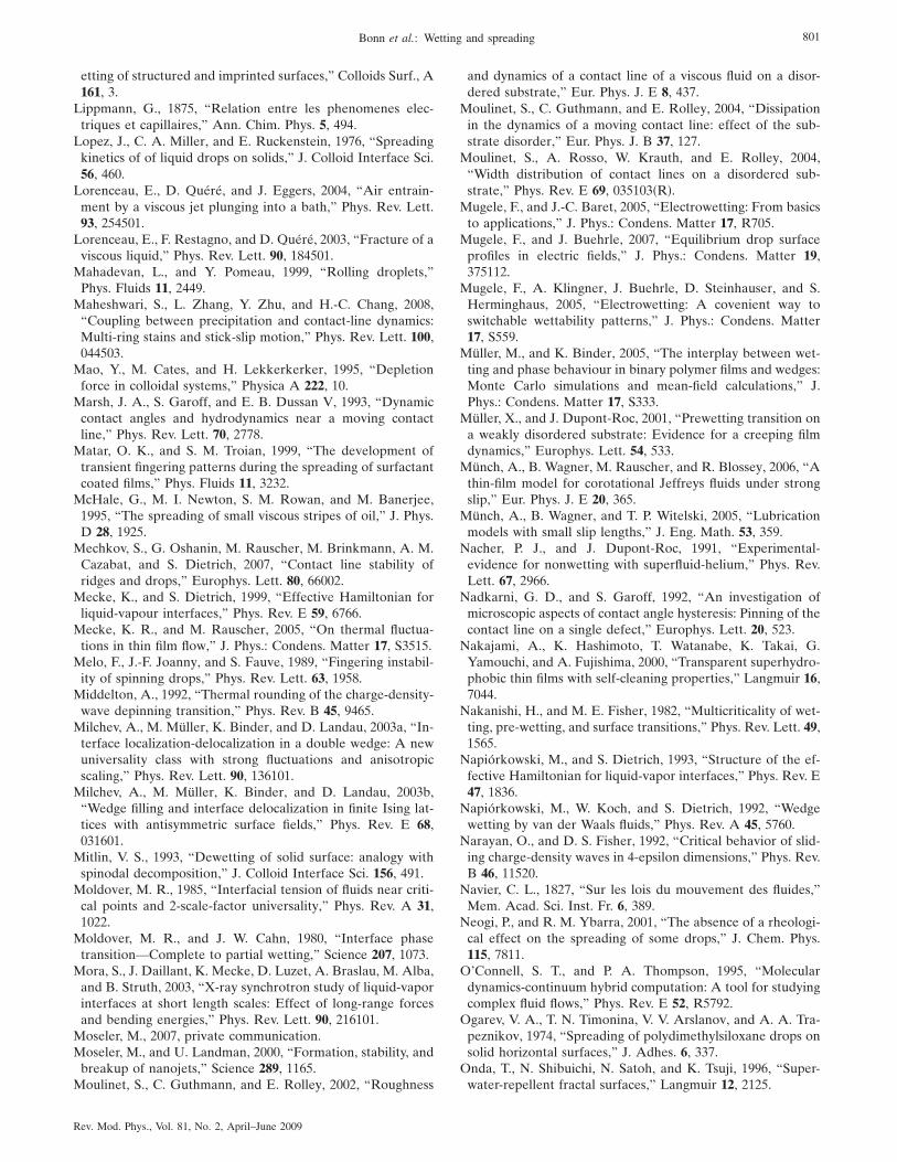
etting of structured and imprinted surfaces,” Colloids Surf., A161, 3.
Lippmann, G., 1875, “Relation entre les phenomenes elec-triques et capillaires,” Ann. Chim. Phys. 5, 494.
Lopez, J., C. A. Miller, and E. Ruckenstein, 1976, “Spreadingkinetics of of liquid drops on solids,” J. Colloid Interface Sci.56, 460.
Lorenceau, E., D. Quéré, and J. Eggers, 2004, “Air entrain-ment by a viscous jet plunging into a bath,” Phys. Rev. Lett.93, 254501.
Lorenceau, E., F. Restagno, and D. Quéré, 2003, “Fracture of aviscous liquid,” Phys. Rev. Lett. 90, 184501.
Mahadevan, L., and Y. Pomeau, 1999, “Rolling droplets,”Phys. Fluids 11, 2449.
Maheshwari, S., L. Zhang, Y. Zhu, and H.-C. Chang, 2008,“Coupling between precipitation and contact-line dynamics:Multi-ring stains and stick-slip motion,” Phys. Rev. Lett. 100,044503.
Mao, Y., M. Cates, and H. Lekkerkerker, 1995, “Depletionforce in colloidal systems,” Physica A 222, 10.
Marsh, J. A., S. Garoff, and E. B. Dussan V, 1993, “Dynamiccontact angles and hydrodynamics near a moving contactline,” Phys. Rev. Lett. 70, 2778.
Matar, O. K., and S. M. Troian, 1999, “The development oftransient fingering patterns during the spreading of surfactantcoated films,” Phys. Fluids 11, 3232.
McHale, G., M. I. Newton, S. M. Rowan, and M. Banerjee,1995, “The spreading of small viscous stripes of oil,” J. Phys.D 28, 1925.
Mechkov, S., G. Oshanin, M. Rauscher, M. Brinkmann, A. M.Cazabat, and S. Dietrich, 2007, “Contact line stability ofridges and drops,” Europhys. Lett. 80, 66002.
Mecke, K., and S. Dietrich, 1999, “Effective Hamiltonian forliquid-vapour interfaces,” Phys. Rev. E 59, 6766.
Mecke, K. R., and M. Rauscher, 2005, “On thermal fluctua-tions in thin film flow,” J. Phys.: Condens. Matter 17, S3515.
Melo, F., J.-F. Joanny, and S. Fauve, 1989, “Fingering instabil-ity of spinning drops,” Phys. Rev. Lett. 63, 1958.
Middelton, A., 1992, “Thermal rounding of the charge-density-wave depinning transition,” Phys. Rev. B 45, 9465.
Milchev, A., M. Müller, K. Binder, and D. Landau, 2003a, “In-terface localization-delocalization in a double wedge: A newuniversality class with strong fluctuations and anisotropicscaling,” Phys. Rev. Lett. 90, 136101.
Milchev, A., M. Müller, K. Binder, and D. Landau, 2003b,“Wedge filling and interface delocalization in finite Ising lat-tices with antisymmetric surface fields,” Phys. Rev. E 68,031601.
Mitlin, V. S., 1993, “Dewetting of solid surface: analogy withspinodal decomposition,” J. Colloid Interface Sci. 156, 491.
Moldover, M. R., 1985, “Interfacial tension of fluids near criti-cal points and 2-scale-factor universality,” Phys. Rev. A 31,1022.
Moldover, M. R., and J. W. Cahn, 1980, “Interface phasetransition—Complete to partial wetting,” Science 207, 1073.
Mora, S., J. Daillant, K. Mecke, D. Luzet, A. Braslau, M. Alba,and B. Struth, 2003, “X-ray synchrotron study of liquid-vaporinterfaces at short length scales: Effect of long-range forcesand bending energies,” Phys. Rev. Lett. 90, 216101.
Moseler, M., 2007, private communication.Moseler, M., and U. Landman, 2000, “Formation, stability, and
breakup of nanojets,” Science 289, 1165.Moulinet, S., C. Guthmann, and E. Rolley, 2002, “Roughness
and dynamics of a contact line of a viscous fluid on a disor-dered substrate,” Eur. Phys. J. E 8, 437.
Moulinet, S., C. Guthmann, and E. Rolley, 2004, “Dissipationin the dynamics of a moving contact line: effect of the sub-strate disorder,” Eur. Phys. J. B 37, 127.
Moulinet, S., A. Rosso, W. Krauth, and E. Rolley, 2004,“Width distribution of contact lines on a disordered sub-strate,” Phys. Rev. E 69, 035103�R�.
Mugele, F., and J.-C. Baret, 2005, “Electrowetting: From basicsto applications,” J. Phys.: Condens. Matter 17, R705.
Mugele, F., and J. Buehrle, 2007, “Equilibrium drop surfaceprofiles in electric fields,” J. Phys.: Condens. Matter 19,375112.
Mugele, F., A. Klingner, J. Buehrle, D. Steinhauser, and S.Herminghaus, 2005, “Electrowetting: A covenient way toswitchable wettability patterns,” J. Phys.: Condens. Matter17, S559.
Müller, M., and K. Binder, 2005, “The interplay between wet-ting and phase behaviour in binary polymer films and wedges:Monte Carlo simulations and mean-field calculations,” J.Phys.: Condens. Matter 17, S333.
Müller, X., and J. Dupont-Roc, 2001, “Prewetting transition ona weakly disordered substrate: Evidence for a creeping filmdynamics,” Europhys. Lett. 54, 533.
Münch, A., B. Wagner, M. Rauscher, and R. Blossey, 2006, “Athin-film model for corotational Jeffreys fluids under strongslip,” Eur. Phys. J. E 20, 365.
Münch, A., B. Wagner, and T. P. Witelski, 2005, “Lubricationmodels with small slip lengths,” J. Eng. Math. 53, 359.
Nacher, P. J., and J. Dupont-Roc, 1991, “Experimental-evidence for nonwetting with superfluid-helium,” Phys. Rev.Lett. 67, 2966.
Nadkarni, G. D., and S. Garoff, 1992, “An investigation ofmicroscopic aspects of contact angle hysteresis: Pinning of thecontact line on a single defect,” Europhys. Lett. 20, 523.
Nakajami, A., K. Hashimoto, T. Watanabe, K. Takai, G.Yamouchi, and A. Fujishima, 2000, “Transparent superhydro-phobic thin films with self-cleaning properties,” Langmuir 16,7044.
Nakanishi, H., and M. E. Fisher, 1982, “Multicriticality of wet-ting, pre-wetting, and surface transitions,” Phys. Rev. Lett. 49,1565.
Napiórkowski, M., and S. Dietrich, 1993, “Structure of the ef-fective Hamiltonian for liquid-vapor interfaces,” Phys. Rev. E47, 1836.
Napiórkowski, M., W. Koch, and S. Dietrich, 1992, “Wedgewetting by van der Waals fluids,” Phys. Rev. A 45, 5760.
Narayan, O., and D. S. Fisher, 1992, “Critical behavior of slid-ing charge-density waves in 4-epsilon dimensions,” Phys. Rev.B 46, 11520.
Navier, C. L., 1827, “Sur les lois du mouvement des fluides,”Mem. Acad. Sci. Inst. Fr. 6, 389.
Neogi, P., and R. M. Ybarra, 2001, “The absence of a rheologi-cal effect on the spreading of some drops,” J. Chem. Phys.115, 7811.
O’Connell, S. T., and P. A. Thompson, 1995, “Moleculardynamics-continuum hybrid computation: A tool for studyingcomplex fluid flows,” Phys. Rev. E 52, R5792.
Ogarev, V. A., T. N. Timonina, V. V. Arslanov, and A. A. Tra-peznikov, 1974, “Spreading of polydimethylsiloxane drops onsolid horizontal surfaces,” J. Adhes. 6, 337.
Onda, T., N. Shibuichi, N. Satoh, and K. Tsuji, 1996, “Super-water-repellent fractal surfaces,” Langmuir 12, 2125.
801Bonn et al.: Wetting and spreading
Rev. Mod. Phys., Vol. 81, No. 2, April–June 2009
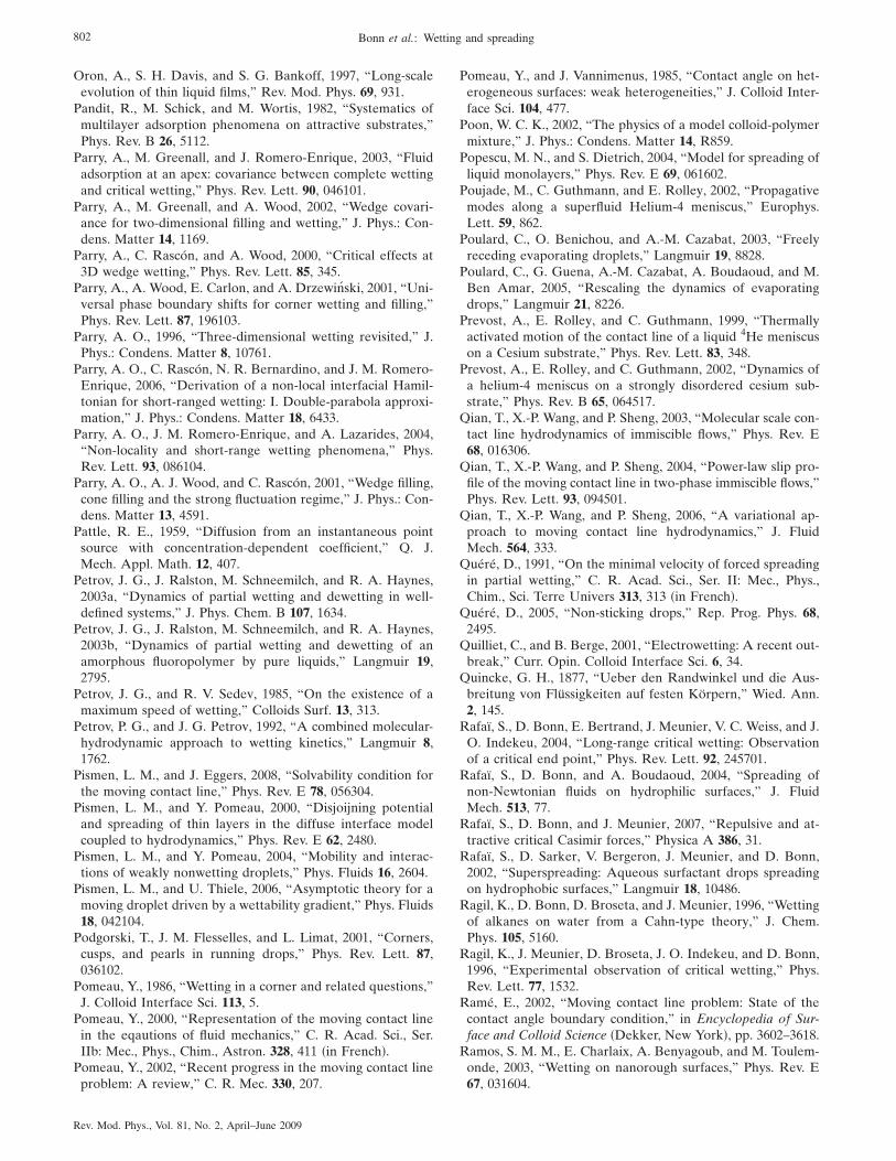
Oron, A., S. H. Davis, and S. G. Bankoff, 1997, “Long-scaleevolution of thin liquid films,” Rev. Mod. Phys. 69, 931.
Pandit, R., M. Schick, and M. Wortis, 1982, “Systematics ofmultilayer adsorption phenomena on attractive substrates,”Phys. Rev. B 26, 5112.
Parry, A., M. Greenall, and J. Romero-Enrique, 2003, “Fluidadsorption at an apex: covariance between complete wettingand critical wetting,” Phys. Rev. Lett. 90, 046101.
Parry, A., M. Greenall, and A. Wood, 2002, “Wedge covari-ance for two-dimensional filling and wetting,” J. Phys.: Con-dens. Matter 14, 1169.
Parry, A., C. Rascón, and A. Wood, 2000, “Critical effects at3D wedge wetting,” Phys. Rev. Lett. 85, 345.
Parry, A., A. Wood, E. Carlon, and A. Drzewinski, 2001, “Uni-versal phase boundary shifts for corner wetting and filling,”Phys. Rev. Lett. 87, 196103.
Parry, A. O., 1996, “Three-dimensional wetting revisited,” J.Phys.: Condens. Matter 8, 10761.
Parry, A. O., C. Rascón, N. R. Bernardino, and J. M. Romero-Enrique, 2006, “Derivation of a non-local interfacial Hamil-tonian for short-ranged wetting: I. Double-parabola approxi-mation,” J. Phys.: Condens. Matter 18, 6433.
Parry, A. O., J. M. Romero-Enrique, and A. Lazarides, 2004,“Non-locality and short-range wetting phenomena,” Phys.Rev. Lett. 93, 086104.
Parry, A. O., A. J. Wood, and C. Rascón, 2001, “Wedge filling,cone filling and the strong fluctuation regime,” J. Phys.: Con-dens. Matter 13, 4591.
Pattle, R. E., 1959, “Diffusion from an instantaneous pointsource with concentration-dependent coefficient,” Q. J.Mech. Appl. Math. 12, 407.
Petrov, J. G., J. Ralston, M. Schneemilch, and R. A. Haynes,2003a, “Dynamics of partial wetting and dewetting in well-defined systems,” J. Phys. Chem. B 107, 1634.
Petrov, J. G., J. Ralston, M. Schneemilch, and R. A. Haynes,2003b, “Dynamics of partial wetting and dewetting of anamorphous fluoropolymer by pure liquids,” Langmuir 19,2795.
Petrov, J. G., and R. V. Sedev, 1985, “On the existence of amaximum speed of wetting,” Colloids Surf. 13, 313.
Petrov, P. G., and J. G. Petrov, 1992, “A combined molecular-hydrodynamic approach to wetting kinetics,” Langmuir 8,1762.
Pismen, L. M., and J. Eggers, 2008, “Solvability condition forthe moving contact line,” Phys. Rev. E 78, 056304.
Pismen, L. M., and Y. Pomeau, 2000, “Disjoijning potentialand spreading of thin layers in the diffuse interface modelcoupled to hydrodynamics,” Phys. Rev. E 62, 2480.
Pismen, L. M., and Y. Pomeau, 2004, “Mobility and interac-tions of weakly nonwetting droplets,” Phys. Fluids 16, 2604.
Pismen, L. M., and U. Thiele, 2006, “Asymptotic theory for amoving droplet driven by a wettability gradient,” Phys. Fluids18, 042104.
Podgorski, T., J. M. Flesselles, and L. Limat, 2001, “Corners,cusps, and pearls in running drops,” Phys. Rev. Lett. 87,036102.
Pomeau, Y., 1986, “Wetting in a corner and related questions,”J. Colloid Interface Sci. 113, 5.
Pomeau, Y., 2000, “Representation of the moving contact linein the eqautions of fluid mechanics,” C. R. Acad. Sci., Ser.IIb: Mec., Phys., Chim., Astron. 328, 411 �in French�.
Pomeau, Y., 2002, “Recent progress in the moving contact lineproblem: A review,” C. R. Mec. 330, 207.
Pomeau, Y., and J. Vannimenus, 1985, “Contact angle on het-erogeneous surfaces: weak heterogeneities,” J. Colloid Inter-face Sci. 104, 477.
Poon, W. C. K., 2002, “The physics of a model colloid-polymermixture,” J. Phys.: Condens. Matter 14, R859.
Popescu, M. N., and S. Dietrich, 2004, “Model for spreading ofliquid monolayers,” Phys. Rev. E 69, 061602.
Poujade, M., C. Guthmann, and E. Rolley, 2002, “Propagativemodes along a superfluid Helium-4 meniscus,” Europhys.Lett. 59, 862.
Poulard, C., O. Benichou, and A.-M. Cazabat, 2003, “Freelyreceding evaporating droplets,” Langmuir 19, 8828.
Poulard, C., G. Guena, A.-M. Cazabat, A. Boudaoud, and M.Ben Amar, 2005, “Rescaling the dynamics of evaporatingdrops,” Langmuir 21, 8226.
Prevost, A., E. Rolley, and C. Guthmann, 1999, “Thermallyactivated motion of the contact line of a liquid 4He meniscuson a Cesium substrate,” Phys. Rev. Lett. 83, 348.
Prevost, A., E. Rolley, and C. Guthmann, 2002, “Dynamics ofa helium-4 meniscus on a strongly disordered cesium sub-strate,” Phys. Rev. B 65, 064517.
Qian, T., X.-P. Wang, and P. Sheng, 2003, “Molecular scale con-tact line hydrodynamics of immiscible flows,” Phys. Rev. E68, 016306.
Qian, T., X.-P. Wang, and P. Sheng, 2004, “Power-law slip pro-file of the moving contact line in two-phase immiscible flows,”Phys. Rev. Lett. 93, 094501.
Qian, T., X.-P. Wang, and P. Sheng, 2006, “A variational ap-proach to moving contact line hydrodynamics,” J. FluidMech. 564, 333.
Quéré, D., 1991, “On the minimal velocity of forced spreadingin partial wetting,” C. R. Acad. Sci., Ser. II: Mec., Phys.,Chim., Sci. Terre Univers 313, 313 �in French�.
Quéré, D., 2005, “Non-sticking drops,” Rep. Prog. Phys. 68,2495.
Quilliet, C., and B. Berge, 2001, “Electrowetting: A recent out-break,” Curr. Opin. Colloid Interface Sci. 6, 34.
Quincke, G. H., 1877, “Ueber den Randwinkel und die Aus-breitung von Flüssigkeiten auf festen Körpern,” Wied. Ann.2, 145.
Rafaï, S., D. Bonn, E. Bertrand, J. Meunier, V. C. Weiss, and J.O. Indekeu, 2004, “Long-range critical wetting: Observationof a critical end point,” Phys. Rev. Lett. 92, 245701.
Rafaï, S., D. Bonn, and A. Boudaoud, 2004, “Spreading ofnon-Newtonian fluids on hydrophilic surfaces,” J. FluidMech. 513, 77.
Rafaï, S., D. Bonn, and J. Meunier, 2007, “Repulsive and at-tractive critical Casimir forces,” Physica A 386, 31.
Rafaï, S., D. Sarker, V. Bergeron, J. Meunier, and D. Bonn,2002, “Superspreading: Aqueous surfactant drops spreadingon hydrophobic surfaces,” Langmuir 18, 10486.
Ragil, K., D. Bonn, D. Broseta, and J. Meunier, 1996, “Wettingof alkanes on water from a Cahn-type theory,” J. Chem.Phys. 105, 5160.
Ragil, K., J. Meunier, D. Broseta, J. O. Indekeu, and D. Bonn,1996, “Experimental observation of critical wetting,” Phys.Rev. Lett. 77, 1532.
Ramé, E., 2002, “Moving contact line problem: State of thecontact angle boundary condition,” in Encyclopedia of Sur-face and Colloid Science �Dekker, New York�, pp. 3602–3618.
Ramos, S. M. M., E. Charlaix, A. Benyagoub, and M. Toulem-onde, 2003, “Wetting on nanorough surfaces,” Phys. Rev. E67, 031604.
802 Bonn et al.: Wetting and spreading
Rev. Mod. Phys., Vol. 81, No. 2, April–June 2009
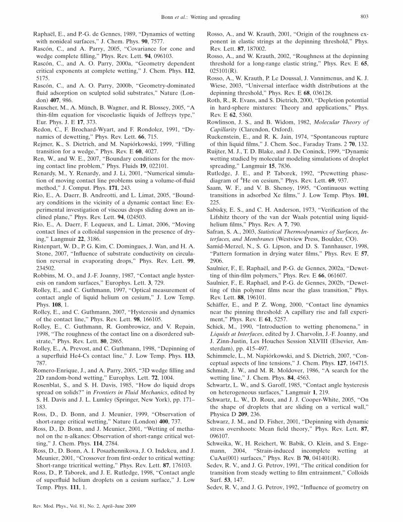
Raphaël, E., and P.-G. de Gennes, 1989, “Dynamics of wettingwith nonideal surfaces,” J. Chem. Phys. 90, 7577.
Rascón, C., and A. Parry, 2005, “Covariance for cone andwedge complete filling,” Phys. Rev. Lett. 94, 096103.
Rascón, C., and A. O. Parry, 2000a, “Geometry dependentcritical exponents at complete wetting,” J. Chem. Phys. 112,5175.
Rascón, C., and A. O. Parry, 2000b, “Geometry-dominatedfluid adsorption on sculpted solid substrates,” Nature �Lon-don� 407, 986.
Rauscher, M., A. Münch, B. Wagner, and R. Blossey, 2005, “Athin-film equation for viscoelastic liquids of Jeffreys type,”Eur. Phys. J. E 17, 373.
Redon, C., F. Brochard-Wyart, and F. Rondolez, 1991, “Dy-namics of dewetting,” Phys. Rev. Lett. 66, 715.
Rejmer, K., S. Dietrich, and M. Napiórkowski, 1999, “Fillingtransition for a wedge,” Phys. Rev. E 60, 4027.
Ren, W., and W. E., 2007, “Boundary conditions for the mov-ing contact line problem,” Phys. Fluids 19, 022101.
Renardy, M., Y. Renardy, and J. Li, 2001, “Numerical simula-tion of moving contact line problems using a volume-of-fluidmethod,” J. Comput. Phys. 171, 243.
Rio, E., A. Daerr, B. Andreotti, and L. Limat, 2005, “Bound-ary conditions in the vicinity of a dynamic contact line: Ex-perimental investigation of viscous drops sliding down an in-clined plane,” Phys. Rev. Lett. 94, 024503.
Rio, E., A. Daerr, F. Lequeux, and L. Limat, 2006, “Movingcontact lines of a colloidal suspension in the presence of dry-ing,” Langmuir 22, 3186.
Ristenpart, W. D., P. G. Kim, C. Domingues, J. Wan, and H. A.Stone, 2007, “Influence of substrate conductivity on circula-tion reversal in evaporating drops,” Phys. Rev. Lett. 99,234502.
Robbins, M. O., and J.-F. Joanny, 1987, “Contact angle hyster-esis on random surfaces,” Europhys. Lett. 3, 729.
Rolley, E., and C. Guthmann, 1997, “Optical measurement ofcontact angle of liquid helium on cesium,” J. Low Temp.Phys. 108, 1.
Rolley, E., and C. Guthmann, 2007, “Hysteresis and dynamicsof the contact line,” Phys. Rev. Lett. 98, 166105.
Rolley, E., C. Guthmann, R. Gombrowicz, and V. Repain,1998, “The roughness of the contact line on a disordered sub-strate,” Phys. Rev. Lett. 80, 2865.
Rolley, E., A. Prevost, and C. Guthmann, 1998, “Depinning ofa superfluid He4-Cs contact line,” J. Low Temp. Phys. 113,787.
Romero-Enrique, J., and A. Parry, 2005, “3D wedge filling and2D random-bond wetting,” Europhys. Lett. 72, 1004.
Rosenblat, S., and S. H. Davis, 1985, “How do liquid dropsspread on solids?” in Frontiers in Fluid Mechanics, edited byS. H. Davis and J. L. Lumley �Springer, New York�, pp. 171–183.
Ross, D., D. Bonn, and J. Meunier, 1999, “Observation ofshort-range critical wetting,” Nature �London� 400, 737.
Ross, D., D. Bonn, and J. Meunier, 2001, “Wetting of metha-nol on the n-alkanes: Observation of short-range critical wet-ting,” J. Chem. Phys. 114, 2784.
Ross, D., D. Bonn, A. I. Posazhennikova, J. O. Indekeu, and J.Meunier, 2001, “Crossover from first-order to critical wetting:Short-range tricritical wetting,” Phys. Rev. Lett. 87, 176103.
Ross, D., P. Taborek, and J. E. Rutledge, 1998, “Contact angleof superfluid helium droplets on a cesium surface,” J. LowTemp. Phys. 111, 1.
Rosso, A., and W. Krauth, 2001, “Origin of the roughness ex-ponent in elastic strings at the depinning threshold,” Phys.Rev. Lett. 87, 187002.
Rosso, A., and W. Krauth, 2002, “Roughness at the depinningthreshold for a long-range elastic string,” Phys. Rev. E 65,025101�R�.
Rosso, A., W. Krauth, P. Le Doussal, J. Vannimenus, and K. J.Wiese, 2003, “Universal interface width distributions at thedepinning threshold,” Phys. Rev. E 68, 036128.
Roth, R., R. Evans, and S. Dietrich, 2000, “Depletion potentialin hard-sphere mixtures: Theory and applications,” Phys.Rev. E 62, 5360.
Rowlinson, J. S., and B. Widom, 1982, Molecular Theory ofCapillarity �Clarendon, Oxford�.
Ruckenstein, E., and R. K. Jain, 1974, “Spontaneous ruptureof thin liquid films,” J. Chem. Soc., Faraday Trans. 2 70, 132.
Ruijter, M. J., T. D. Blake, and J. De Coninck, 1999, “Dynamicwetting studied by molecular modeling simulations of dropletspreading,” Langmuir 15, 7836.
Rutledge, J. E., and P. Taborek, 1992, “Prewetting phase-diagram of 4He on cesium,” Phys. Rev. Lett. 69, 937.
Saam, W. F., and V. B. Shenoy, 1995, “Continuous wettingtransitions in adsorbed Xe films,” J. Low Temp. Phys. 101,225.
Sabisky, E. S., and C. H. Anderson, 1973, “Verification of theLifshitz theory of the van der Waals potential using liquid-helium films,” Phys. Rev. A 7, 790.
Safran, S. A., 2003, Statistical Thermodynamics of Surfaces, In-terfaces, and Membranes �Westview Press, Boulder, CO�.
Samid-Merzel, N., S. G. Lipson, and D. S. Tannhauser, 1998,“Pattern formation in drying water films,” Phys. Rev. E 57,2906.
Saulnier, F., E. Raphaël, and P.-G. de Gennes, 2002a, “Dewet-ting of thin-film polymers,” Phys. Rev. E 66, 061607.
Saulnier, F., E. Raphaël, and P.-G. de Gennes, 2002b, “Dewet-ting of thin polymer films near the glass transition,” Phys.Rev. Lett. 88, 196101.
Schäffer, E., and P. Z. Wong, 2000, “Contact line dynamicsnear the pinning threshold: A capillary rise and fall experi-ment,” Phys. Rev. E 61, 5257.
Schick, M., 1990, “Introduction to wetting phenomena,” inLiquids at Interfaces, edited by J. Charvolin, J.-F. Joanny, andJ. Zinn-Justin, Les Houches Session XLVIII �Elsevier, Am-sterdam�, pp. 415–497.
Schimmele, L., M. Napiórkowski, and S. Dietrich, 2007, “Con-ceptual aspects of line tensions,” J. Chem. Phys. 127, 164715.
Schmidt, J. W., and M. R. Moldover, 1986, “A search for thewetting line,” J. Chem. Phys. 84, 4563.
Schwartz, L. W., and S. Garoff, 1985, “Contact angle hysteresison heterogeneous surfaces,” Langmuir 1, 219.
Schwartz, L. W., D. Roux, and J. J. Cooper-White, 2005, “Onthe shape of droplets that are sliding on a vertical wall,”Physica D 209, 236.
Schwarz, J. M., and D. Fisher, 2001, “Depinning with dynamicstress overshoots: Mean field theory,” Phys. Rev. Lett. 87,096107.
Schweika, W., H. Reichert, W. Babik, O. Klein, and S. Enge-mann, 2004, “Strain-induced incomplete wetting atCuAu�001� surfaces,” Phys. Rev. B 70, 041401�R�.
Sedev, R. V., and J. G. Petrov, 1991, “The critical condition fortransition from steady wetting to film entrainment,” ColloidsSurf. 53, 147.
Sedev, R. V., and J. G. Petrov, 1992, “Influence of geometry on
803Bonn et al.: Wetting and spreading
Rev. Mod. Phys., Vol. 81, No. 2, April–June 2009
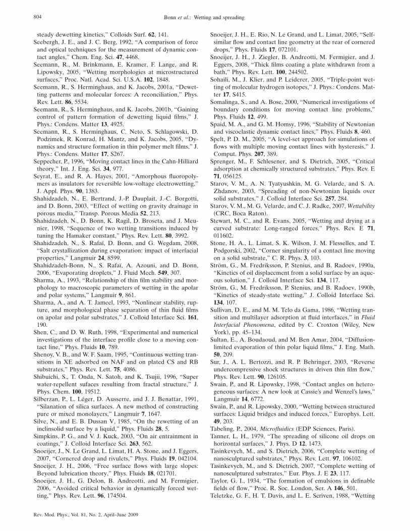
steady dewetting kinetics,” Colloids Surf. 62, 141.Seebergh, J. E., and J. C. Berg, 1992, “A comparison of force
and optical techniques for the measurement of dynamic con-tact angles,” Chem. Eng. Sci. 47, 4468.
Seemann, R., M. Brinkmann, E. Kramer, F. Lange, and R.Lipowsky, 2005, “Wetting morphologies at microstructuredsurfaces,” Proc. Natl. Acad. Sci. U.S.A. 102, 1848.
Seemann, R., S. Herminghaus, and K. Jacobs, 2001a, “Dewet-ting patterns and molecular forces: A reconciliation,” Phys.Rev. Lett. 86, 5534.
Seemann, R., S. Herminghaus, and K. Jacobs, 2001b, “Gainingcontrol of pattern formation of dewetting liquid films,” J.Phys.: Condens. Matter 13, 4925.
Seemann, R., S. Herminghaus, C. Neto, S. Schlagowski, D.Podzimek, R. Konrad, H. Mantz, and K. Jacobs, 2005, “Dy-namics and structure formation in thin polymer melt films,” J.Phys.: Condens. Matter 17, S267.
Seppecher, P., 1996, “Moving contact lines in the Cahn-Hilliardtheory,” Int. J. Eng. Sci. 34, 977.
Seyrat, E., and R. A. Hayes, 2001, “Amorphous fluoropoly-mers as insulators for reversible low-voltage electrowetting,”J. Appl. Phys. 90, 1383.
Shahidzadeh, N., E. Bertrand, J.-P. Dauplait, J.-C. Borgotti,and D. Bonn, 2003, “Effect of wetting on gravity drainage inporous media,” Transp. Porous Media 52, 213.
Shahidzadeh, N., D. Bonn, K. Ragil, D. Broseta, and J. Meu-nier, 1998, “Sequence of two wetting transitions induced bytuning the Hamaker constant,” Phys. Rev. Lett. 80, 3992.
Shahidzadeh, N., S. Rafaï, D. Bonn, and G. Wegdam, 2008,“Salt crystallization during evaporation: impact of interfacialproperties,” Langmuir 24, 8599.
Shahidzadeh-Bonn, N., S. Rafaï, A. Azouni, and D. Bonn,2006, “Evaporating droplets,” J. Fluid Mech. 549, 307.
Sharma, A., 1993, “Relationship of thin film stability and mor-phology to macroscopic parameters of wetting in the apolarand polar systems,” Langmuir 9, 861.
Sharma, A., and A. T. Jameel, 1993, “Nonlinear stability, rup-ture, and morphological phase separation of thin fluid filmson apolar and polar substrates,” J. Colloid Interface Sci. 161,190.
Shen, C., and D. W. Ruth, 1998, “Experimental and numericalinvestigations of the interface profile close to a moving con-tact line,” Phys. Fluids 10, 789.
Shenoy, V. B., and W. F. Saam, 1995, “Continuous wetting tran-sitions in XE adsorbed on NAF and on plated CS and RBsubstrates,” Phys. Rev. Lett. 75, 4086.
Shibuichi, S., T. Onda, N. Satoh, and K. Tsujii, 1996, “Superwater-repellent sufaces resulting from fractal structure,” J.Phys. Chem. 100, 19512.
Silberzan, P., L. Léger, D. Ausserre, and J. J. Benattar, 1991,“Silanation of silica surfaces. A new method of constructingpure or mixed monolayers,” Langmuir 7, 1647.
Silve, N., and E. B. Dussan V, 1985, “On the rewetting of aninclinsolid surface by a liquid,” Phys. Fluids 28, 5.
Simpkins, P. G., and V. J. Kuck, 2003, “On air entrainment incoatings,” J. Colloid Interface Sci. 263, 562.
Snoeijer, J., N. Le Grand, L. Limat, H. A. Stone, and J. Eggers,2007, “Cornered drop and rivulets,” Phys. Fluids 19, 042104.
Snoeijer, J. H., 2006, “Free surface flows with large slopes:Beyond lubrication theory,” Phys. Fluids 18, 021701.
Snoeijer, J. H., G. Delon, B. Andreotti, and M. Fermigier,2006, “Avoided critical behavior in dynamically forced wet-ting,” Phys. Rev. Lett. 96, 174504.
Snoeijer, J. H., E. Rio, N. Le Grand, and L. Limat, 2005, “Self-similar flow and contact line geometry at the rear of cornereddrops,” Phys. Fluids 17, 072101.
Snoeijer, J. H., J. Ziegler, B. Andreotti, M. Fermigier, and J.Eggers, 2008, “Thick films coating a plate withdrawn from abath,” Phys. Rev. Lett. 100, 244502.
Sohaili, M., J. Klier, and P. Leiderer, 2005, “Triple-point wet-ting of molecular hydrogen isotopes,” J. Phys.: Condens. Mat-ter 17, S415.
Somalinga, S., and A. Bose, 2000, “Numerical investigations ofboundary conditions for moving contact line problems,”Phys. Fluids 12, 499.
Spaid, M. A., and G. M. Homsy, 1996, “Stability of Newtonianand viscoelastic dynamic contact lines,” Phys. Fluids 8, 460.
Spelt, P. D. M., 2005, “A level-set approach for simulations offlows with multiple moving contact lines with hysteresis,” J.Comput. Phys. 207, 389.
Sprenger, M., F. Schlesener, and S. Dietrich, 2005, “Criticaladsorption at chemically structured substrates,” Phys. Rev. E71, 056125.
Starov, V. M., A. N. Tyatyushkin, M. G. Velarde, and S. A.Zhdanov, 2003, “Spreading of non-Newtonian liquids oversolid substrates,” J. Colloid Interface Sci. 257, 284.
Starov, V. M., M. G. Velarde, and C. J. Radke, 2007, Wettability�CRC, Boca Raton�.
Stewart, M. C., and R. Evans, 2005, “Wetting and drying at acurved substrate: Long-ranged forces,” Phys. Rev. E 71,011602.
Stone, H. A., L. Limat, S. K. Wilson, J. M. Flesselles, and T.Podgorski, 2002, “Corner singularity of a contact line movingon a solid substrate,” C. R. Phys. 3, 103.
Ström, G., M. Fredriksson, P. Stenius, and B. Radoev, 1990a,“Kinetics of oil displacement from a solid surface by an aque-ous solution,” J. Colloid Interface Sci. 134, 117.
Ström, G., M. Fredriksson, P. Stenius, and B. Radoev, 1990b,“Kinetics of steady-state wetting,” J. Colloid Interface Sci.134, 107.
Sullivan, D. E., and M. M. Telo da Gama, 1986, “Wetting tran-sition and multilayer adsorption at fluid interfaces,” in FluidInterfacial Phenomena, edited by C. Croxton �Wiley, NewYork�, pp. 45–134.
Sultan, E., A. Boudaoud, and M. Ben Amar, 2004, “Diffusion-limited evaporation of thin polar liquid films,” J. Eng. Math.50, 209.
Sur, J., A. L. Bertozzi, and R. P. Behringer, 2003, “Reverseundercompressive shock structures in driven thin film flow,”Phys. Rev. Lett. 90, 126105.
Swain, P., and R. Lipowsky, 1998, “Contact angles on hetero-geneous surfaces: A new look at Cassie’s and Wenzel’s laws,”Langmuir 14, 6772.
Swain, P., and R. Lipowsky, 2000, “Wetting between structuredsurfaces: Liquid bridges and induced forces,” Europhys. Lett.49, 203.
Tabeling, P., 2004, Microfluidics �EDP Sciences, Paris�.Tanner, L. H., 1979, “The spreading of silicone oil drops on
horizontal surfaces,” J. Phys. D 12, 1473.Tasinkevych, M., and S. Dietrich, 2006, “Complete wetting of
nanosculptured substrates,” Phys. Rev. Lett. 97, 106102.Tasinkevych, M., and S. Dietrich, 2007, “Complete wetting of
nanosculptured substrates,” Eur. Phys. J. E 23, 117.Taylor, G. I., 1934, “The formation of emulsions in definable
fields of flow,” Proc. R. Soc. London, Ser. A 146, 501.Teletzke, G. F., H. T. Davis, and L. E. Scriven, 1988, “Wetting
804 Bonn et al.: Wetting and spreading
Rev. Mod. Phys., Vol. 81, No. 2, April–June 2009
hydrodynamics,” Rev. Phys. Appl. 23, 989.Thiele, U., 2003, “Open questions and promising new fields in
dewetting,” Eur. Phys. J. E 12, 409.Thiele, U., and E. Knobloch, 2003, “Front and back instability
of a liquid film on a slightly inclined plane,” Phys. Fluids 15,892.
Thiele, U., K. Neuffer, M. Bestehorn, Y. Pomeau, and M. G.Velarde, 2002, “Sliding drops on an inclined plane,” ColloidsSurf., A 206, 87.
Thompson, P. A., and M. O. Robbins, 1989, “Simulations ofcontact-line motion: Slip and the dynamic contact angle,”Phys. Rev. Lett. 63, 766.
Thompson, P. A., and S. M. Troian, 1997, “A general boundarycondition for liquid flow at solid surfaces,” Nature �London�389, 360.
Trejo, L. M., J. Garcia, C. Varea, and A. Robledo, 1988, “Pos-sibility of continuous wetting transition at the liquid-vaporinterface of the binary liquid mixture cyclohexane+acetonitrile,” Europhys. Lett. 7, 537.
Troian, S., X. Wu, and S. A. Safran, 1989, “Fingering instabilityin thin wetting films,” Phys. Rev. Lett. 62, 1496.
Troian, S. M., E. Herbolzheimer, S. A. Safran, and J.-F.Joanny, 1989, “Fingering instability of driven spreadingfilms,” Europhys. Lett. 10, 25.
Tuinier, R., J. Rieger, and C. G. de Kruif, 2003, “Depletion-induced phase separation in colloid-polymer mixtures,” Adv.Colloid Interface Sci. 103, 1.
Valignat, M. P., N. Fraysse, A.-M. Cazabat, F. Heslot, and P.Levinson, 1993, “An ellipsometric study of layered droplets,”Thin Solid Films 234, 475.
Vandembroucq, D., R. Skoe, and S. Roux, 2004, “Univeraldepinning force fluctuations of an elastic line: Application tofinite temperature behavior,” Phys. Rev. E 70, 051101.
van Hameren, R., et al., 2006, “Macroscopic hierarchical sur-face patterning of porphyrin trimers via self-assembly anddewetting,” Science 314, 1433.
Vilmin, T., and E. Raphaël, 2005, “Dewetting of thin viscoelas-tic polymer films on slippery substrates,” Europhys. Lett. 72,781.
Vilmin, T., E. Raphaël, P. Damman, S. Sclavons, S. Gabriele,M. Hamieh, and G. Reiter, 2006, “The role of nonlinear fric-tion in the dewetting of thin polymer films,” Europhys. Lett.73, 906.
Voinov, O. V., 1976, “Hydrodynamics of wetting,” Fluid Dyn.11, 714 �English translation�.
Voinov, O. V., 1977, “Inclination angles of the boundary inmoving liquid layers,” J. Appl. Mech. Tech. Phys. 18, 216�English translation�.
Voinov, O. V., 1995, “Motion of line of contact of three phaseson a solid: Thermodynmics and asymptotic theory,” Int. J.Multiphase Flow 21, 801.
Voinov, O. V., 2000a, “Wetting: Inverse dynamic problem andequations for microscopic parameters,” J. Colloid InterfaceSci. 226, 5.
Voinov, O. V., 2000b, “Wetting line dynamics in the process ofdrop spreading,” J. Colloid Interface Sci. 226, 22.
Voinov, O. V., 2002, “Dynamics of wetting of a solid by a liq-uid: Movement of thin liquid films,” in Encyclopedia of Sur-face and Colloid Science �Dekker, New York�, pp. 1546–1559.
Vrij, A., 1966, “Possible mechanism for the spontaneous rup-ture of thin, free liquid films,” Discuss. Faraday Soc. 42, 23.
Vrij, A., 1976, “Polymers at interfaces and the interactions incolloidal dispersions,” Pure Appl. Chem. 48, 471.
Warner, M. R. E., R. V. Craster, and O. K. Matar, 2004, “Fin-gering phenomena associated with insoluble surfactantspreading on thin liquid films,” J. Fluid Mech. 510, 169.
Wayner, P. C., 1993, “Spreading of a liquid film with a finitecontact angle by the evaporation/condensation process,”Langmuir 9, 294.
Webb, E. B., III, G. S. Grest, and D. R. Heine, 2003, “Precur-sor film controlled wetting of Pb on Cu,” Phys. Rev. Lett. 91,236102.
Weidner, D. E., and L. W. Schwartz, 1994, “Contact-line mo-tion of shear-thinning liquids,” Phys. Fluids 6, 3535.
Weiss, V. C., E. Bertrand, S. Rafaï, J. O. Indekeu, and D.Bonn, 2007, “Effective exponents in the long-range criticalwetting of alkanes on aqueous substrates,” Phys. Rev. E 76,051602.
Weiss, V. C., and J. O. Indekeu, 2003, “Effect of ion hydrationon the first-order transition in the sequential wetting of hex-ane on brine,” J. Chem. Phys. 118, 10741.
Wenzel, R. N., 1936, “Resistance of solid surfaces to wetting bywater,” Ind. Eng. Chem. 28, 988.
Werner, A., M. Müller, F. Schmid, and K. Binder, 1999, “Effectof long range forces on the interfacial profiles in thin binarypolymer films,” J. Chem. Phys. 110, 1221.
Wessels, P. P. F., M. Schmidt, and H. Löwen, 2004, “The con-tact angle of the colloidal liquid-gas interface and a hardwall,” J. Phys.: Condens. Matter 16, S4169.
Wijting, W. K., N. A. M. Besseling, and M. A. Cohen-Stuart,2003a, “Wetting behavior in colloid-polymer mixtures at dif-ferent substrates,” J. Phys. Chem. B 107, 10565.
Wijting, W. K., N. A. M. Besseling, and M. A. Cohen-Stuart,2003b, “Wetting in a colloidal liquid-gas system,” Phys. Rev.Lett. 90, 196101.
Wu, S., 1982, “Modifications of polymer surfaces: Mechanismsof wettability and bondability improvements,” in Polymer In-terfaces and Adhesion �Dekker, New York�, pp. 279–329.
Yang, S., H. Tan, D. Yan, E. Nies, and A. Shi, 2007, “Effect ofpolydispersity on the depletion interaction in nonadsorbingpolymer solutions,” Phys. Rev. E 75, 061803.
Young, T., 1805, “An essay on the cohesion of fluids,” Philos.Trans. R. Soc. London 95, 65.
Zapperi, S., P. Cizeau, G. Durin, and H. E. Stanley, 1998, “Dy-namics of a ferromagnetic domain wall: Avalanches, depin-ning transition, and the Barkhausen effect,” Phys. Rev. B 58,6353.
805Bonn et al.: Wetting and spreading
Rev. Mod. Phys., Vol. 81, No. 2, April–June 2009