Embed Size (px)
Citation preview
e....,.1111•-
BUSINESS OFFICE AND CUSTOMER SERVICE TELEPHONE NUMBERS
Customer Service Phone Number.
570-819-4844 or Toll-Free 1-800-962-1212. Staff is available Monday through Friday from 7:30 a.m. to 4:00 p.m.
Customer Service Office.
One UGI Center {Bldg. A-2) Wilkes-Barre, PA 18711-0600 Open Mon. through Fri., 7:30 a.m.- 4:00 p.m.
Table of Contents.htm
U G I Th is page last modffied: 07 August 2009 (individual sections indicate last date modified)
FORWABD
This manual covers the general conditions that apply to the
furnishing of electricity on the UGI Corporation system, and must
be adhered to in all respects by those customers receiving electric
service from the Company,
Changes and additions to these rules will be required from
time to time, Revisions will be mailed to those persons on record
as having a copy of this manual.
Section 1
Section 2
TABLE OF CON'IEm.'S
Introductory Information
Business Office and Customer Service Phone Numbers •••••••••• •• • • • • • • • •
Introduction • • • • • • • • • • • • • • • • • • • • •
Definitions
General
• • • • • • • • • • • • • • • .. ...... • •
A. Initial Inquiry ••• • • • • • • • • • . . . .. . .. B. Services Available • • • • • • • • • • • • • • • •
c.
D.
E.
customer Responsibility. • • • • • • • • • • • • •
1. Application for Service • • • • • • • • • • •
2. Right-of-Way • • • • • • • • • • • • • • • • •
3. Tree Tr:bm:fng . . . . . . . . . . . . . . .. . 4. Inspections • • • • • • • • • • • • • • • • •
s. Metering Devices and gquipment ••• • • • • •
6. Connection of MUltiple Conductors • • • • • •
7. Change of Connected Load • , • , • • • • • • •
8. Change or Relocation of Company Facilities • •
9. Upgrading or Replacement of Service . ... . . . 10, Liability for Damages • • • • • • • • • • • •
Company Responsibility • • • • • • • • • • • • • •
1.
2.
Company Installation.
Company OWned Services
• •
. . • • • • • • • • • •
• • • • • • • • • •
3. Service to Motors • • • • • • • • • • • • • •
4. customer Information. . .. . . . • • • .. ... . . 5. Identification. • • • • • . . . .. . . . . . .
Rate Information . . . . . . . .. . . . . . . . . .
1-1
1-2
1-3
2-1
2-1
2-1
2-1
2-2
2-2
2-2
2-2
2-3
2-3
2-3
2-4
2-4
2-4
2-5
2-6
2-6
2-6
2-6
APPENDICES
A, APPROVED MEl'ER SERVICE DEVICES
B.
TABLE 1
TABLE 2
TABLE 3
TABLE 4
TABLE 5
TABLE 6
TABLE 7
TABLE 8
TABLE 9
Single-Phase Overhead Meter Troughs
Single-Phase Underground Meter.Troughs
Single-Phase Multi-Meter Trough, End Wire Compartment
Single-Phase Multi-Meter Trough, Center Wire Compartment
Single-Phase, All-in-One Multi-Meter Trough
Single-Phase, Stacked (Gangable) Multi-Meter Trough
Single-Phase, Mobile Home Meter Pedestals
Polyphase, Single Position
Polyphase, Multi-Position
TABLE 10 -- Polyphase, Stacked (Gangable) Multi-Meter Trough
TABLE 11
SKETCHES
SKETCH 1
SKETCH 2
SKETCH 3
SKETCH 4
SKETCH 5
SKETCH 6
SKETCH 7
SKETCH 8
SKETCH 9
Single-Phase, Meter Trough/Load Center
Typical 3-Wire Te11porary - Overhead Service Structure
-- Typical Temporary Underground Service
Typical Overhead Service 100 Amp and 200 Amp
Typical Overhead Service 300 Amp and 400 Amp
Typical Mast Service
Service Drop Attachllent to Customer-Owned Service and Meter Pole - Overhead Service to Overhead Distribution
Service Drop Attachllent to Customer-Owned Service and Meter Pole - Overhead Service to Underground Distri!l-ution
Specifications for Customer Entrance Equipment 100 Amp and 200 Amp Residential Underground Service
Customer Entrance Equipment:. 300 Amp and 400 Amp Underground Service
SKETOH 10 -- Typical Cust011er Installed Underground
SKEI'CH 11 Wiring Diagram for Single-Phase Transformer Rated Meter, Overhead or Underground Service
SKETCH 12 Specification for Trenching and Backfilling
SKETCH 13 Typical Individual Overhead Mobile Home Pole Service
SKEl'CH 14 Typical Individual Underground Mobile Home Pole Service
SKEl'CH 15 Multi-Meter Installation
SKETCH 16 Connections for Self-Contained Meters
SKETCH 17 Wiring Diagram, Three-Phase 120/240 Volt Service Instru11ent Transforaer Metered with Quadraplex Service Wire
SKEl'CH 18 -- Wiring Diagram, Three-Phase 120/240 Volt Service Instrument Transformer Metered With Open Wire Service
SKETCH 19 -- Wiring Diagram, Three-Phase 120/240 Volt Mast Service, Instruaent Transformer Metered With Quadraplex Service Wire
SKETCH 20 -- Wiring Diagram, Three-Phase 120/208 Volt Instrument Transformer Metered With Quadraplex Service Wire
SKEl'CH 21 Wiring Diagram, Three-Phase 120/208 Volt Instrument Transfol'ller Metered With Open Wire Service
SKEI'CH 22 -- Wiring Diagram, Three-Phase 120/208 Volt Mast Service, Instru11ent Transformer Metered With Quadraplex Service Wire
SKETCH 23 Wiring Diagram, Three-Phase, Three-Wire, 48o Volt Service Instrument Transformer Metered With Open Wire Service
SKETCH 24 Wiring Diagram, Three-Phase 120/240 Volt Underground Service, Instrument Transformer Metered
SKETCH 25 Wiring Diagram, Three-Phase 120/208 Volt Underground Service, Instrument Transformer Metered
SKETCH 26 Typical Customer Installed Underground Conduit -Company Installed Service Conductors

INTRODUCTION
This manual presents the electric service requirements of the Company
relative to service entrances. metering, and the installation of certain
utilization equipment. The information given is not a complete set of rules
governing the installation of electric wiring or apparatus. It covers only
those points in which the customer, the architect, the engineer, the
electrical contractor, and the Company are mutually interested, and the
knowledge of which will serve to prevent unnecessary delays or expense in
furnishing service. Nothing contained herein is intended in any way to
conflict with the requirements of the National Electric Code or with any
municipal ordinance applying to electrical installations,
Special conditions may arise which would be impracticable to cover in
a book of this type, and to such cases the Company will be pleased to give
attention on request.
The information herein must not be construed to conflict, in any·way,
with the "Electric Service Tariff," issued by the Company,
1')/~1/i:1!1
DEFINITIONS
COMPANY--UGI Corporation, Electric Utility Division.
CUSTOMER--The corporation, municipality, governmental agency, association, partnership or individual served by or using electric service supplied by the Company.
VOLTAGE--Nwnerical voltages mentioned are to be construed as nominal values.
SERVICE--As used herein refers to the supply of the Company's product "electric energy" to the customer.
COMPANY POLE--A Company-owned pole or a pole owned by another utility company with whom the company has an agreement or understanding for joint use of poles.
SERVICE INSTALLATION--The connection between the Company's distribution system and the customer's service equipment is a service installation and is commonly referred to as "a service." This generally consists of:
Service Drop or Service Wires--That portion of an overhead service. installation supplied by the Company between.its pole or aerial support and the point of connection to the customer's service entrance conductors.
Service Lateral--That portion of an underground service installation supplied by the Company between its overhead or underground distribution mains and the point of connection to the customer's service equipment.
Service Entrance Conductors--That portion of an overhead or underground service installation supplied by the customer between the Company's service drop or service lateral and the customer's service equipment.
POINT OF DELIVERY--The point in or on a premises where the Company's overhead service drop or underground service lateral connects to the customer's service entrance conductors. The location is designated by the Company.
PREMISES--A building, group of buildings And/or contiguous parcels of land under the control of a customer-and devoted to the conduct of a single business. A building is one premises even though occupied by two or more customers. Adjoining buildings under one roof but separated completely from each other by vertical fire walls are considered as separate premises.
NATIONAL ELECTRICAL CODE--The standard as recommended by the National Fire Protection Association and adopted by the American National Standards Institute in effect at any given time for electrical wiring and apparatus.
NATIONAL ELECTRICAL SAFETY CODE--The rules published by the Institute of Electrical and Electronics Engineers applying to grounding, installation, maintenance and operation of electric supply, communication, utilization equipment, lines and facilities which have been adopted as standard by the American National Standards Institute.
COMPANY OFFICE-·The Business Office at 247 WYoming Avenue, Kingston, Pennsylvania.
SECTION 2 - GENERAL
A. Initial Inquiry - In order to avoid additional expense and minimize
delays, UGI should be contacted before work has started on any electric ser
vice installation. An authorized Company representative will specify the -service location and obtain information necessary to properly supply the
service and apply the provisions of the Collipany's tariff. The Company may
refuse to comnence service when, in the Company's opinion, the customer's
installation does not conform to UGI' s tariff. Furthemoie, the customer
is responsible for changes in the service installation required by the Com
pany before service is supplied.
B. Services Available - The Company supplies alternating current only,
at a llOlllinal frequency of 60 hertz. The min:lmm service size normally
accepted by the Company is 100 amp, single-phase, three wire. (Single
phase, two wire service is available for limited loads, such as, traffic
signals, small signs, telephone booths, etc.) Available voltages are as
specified in the Company's tariff. However, not all service voltages are
available in all areas. Before purchasing electrical equipment or proceeding
with any wiring, information regarding the type of service available should
be obtained from the Company.
c. customer Responsibility
1. Application for Service - The CUstoiaer must notify the Company
well in advance of the date service is desired. It may be necessary to
complete an application for service at the Company office and in some cases
deposits are required. (Note: The receipt of a Fire Underwriter's inspection
at the Company office does !!2! constitute an application for service.) The
following information must be supplied before service will be rendered:
customer account number (if not a new installation), Customer name, customer
12/3l/81 Page 2-1
phone number(s), service and mailing address, nearest UGI pole number
(10-digit), load data, and type of dwelling or business.
Z, Right-of-Way - Where necessary, the customer shall provide
an adequate right-of-way for UGI to supply service to bis premises. An
adequate right-of-way will consist of a strip of land as specified by the
Company which must remain open and accessible so that the Company can per
form line improvements, clearance, and maintenance as may be from time tQ
time required.
3. Tree Trimming - If tree tr1lDIDing is required to accOt11110date
the installation of any power lines on private property, it will be the
customer's responsibility to provide the initial trfaming as directed by
the Company. 'l'he Company will perform subsequent trinming as it considers
necessary to maintain adequate clearance to its facilities.
4. Inspections - The wiring and appliances on the premises of
the customer must be installed in accordance with and ,conform to the latest
rules and requirements of the National Electrical Code, and other such state
or municipal regulations as may be applicable. It will be the Customer's
responsibility to obtain all necessary electrical inspections prior to con--= nection by the Company. Furthermore, the Company shall have the right, but
shall not be obligated, to exsrn1ne the Customer's installation at the t:lme
service is first supplied or at a later time. If at any time, the Company
finds the wiring, fixtures, or appliances of the customer to be defective
or dangerous, the customer will be informed and service may be refused or
discontinued unless the condition is corrected. The Company's responsibility
extends only to the supply of service at the point of delivery.
5. Metering Devices and Equipment - The Customer shall provide,
without charge, a suitable location for the meter or rneters, transformer or
transformers, or other equipment of the Company along with an adequate point
lZ/31/81 Page Z-2
of attachment for the service drop. The location of these items will be
specified by the Company and must be of convenient access to meter readers
or inspectors. Meters must be located between four (4-) and six (6) feet
above final grade.
Tampering, interferring with, or breaking of seals on meters,
switches, or other equipment of the Company installed on the Customer's
premises is prohibited. Offenders will be prosecuted to the full extent of
the law.
6. Connection of Multiple Conductors - When a customer installs
a service entrance consisting of two or more conductors per phase, it is
the customer's responsibility to install, own, and maintain the necessary
equipment to bring all conductors for each phase and the neutral to a
coamon single connection. For specific information regarding situations
of this nature the Company should be contacted.
7. Change of Connected Load - When a customer's service is con
nected to the Company's system, arrangements are made for meters, trans
formers, and other equipment to supply the load at that time. It is
essential that customers notify the Company of any material increase or
decrease in load. It is also advisable that the customer consult .the
Company regarding equipment so that the proper type will be obtained. The
Company will hold the customer liable for any damages caused by increases
in load added to its system without permission.
8. Change or Relocation of Company Facilities - Any alterations
or changes in service connections, or relocation of service connections, or
Company's facilities supplying individual customers shall be at the expense
of the Customer when any of said contingencies are requested by the Customer
(and are for the customers benefit).
12/31/81 Page 2-l
.. 9. Upgrading or Replacement of Service - If existing service
entrance equipment is upgraded or replaced, the customer shall provide a
safe means of maintaining electrical service until the required inspections
are obtained and the Company permanently connects the new entrance equip
ment to its lines. Under no circumstances will the Company allow two
meters to be installed for the purpose of allowing the customer to trans
fer load from one panel to another. The Company will make only one (l)
trip to a premises for upgrading or replacing of service equipment.
10. Uability for Damages~ The Company assumes no responsibility
for any damage done by, or resulting from any defect in the wiring, fixtures,
or appliances of the customer, In the event that any loss or damage to
property of the Company, or any accident or injury to persons is caused
by or results from the negligence or wrongful set of the customer, bis
agents or employees,the cost of the necessary repairs or replacement or
injury shall be paid by the Customer to the Company; and, any liability
othet:Wise resulting shall be the responsibility of the Customer.
D, Company Responsibility - The COmpany will supply electric service
of the highest quality consistent with reasonable cost. However, the Com
pany cannot guarantee continuous uninterrupted service to any customer
and will not assume responsibility for damages resulting from its inter-
ruption,
l. Company Installation - The Company will provide the necessary
equipment for service up to the point of delivery along with necessary
metering devices, after the customer's responsibilities have been met,
only one source of supply to a premises at a single point of delivery will
be allowed in most cases, The point of deiivery on overhead service is the
point of connection to the customer's service entrance conductors. On
12/31/81 Page 2-4
underground residential service, installed by UGI, the point of delivery
is normally the line side of the Customer's meter trough. (UGI will not
install underground services to coamercial or industrial Customers.) The
point of delivery for any customer installed underground is at the point
of connection to the Company's supply system.
overhead service is normally supplied at no charge to cus
tomers within 100 feet of existing Company facilities. If the customer
requires an unusually long service, more than 100 feet from Company facil
ities, or desires undergrOllDd service, minimum monthly bills and/or aid
to construction charges -y apply. The Company should be contacted for
information regarding these situations.
Connection of Company facilities and customer equipment shall
be made only by authorized UGI employees. Every reasonable effort will be
made to coordinate work with the Customer on both new and upgraded instal
lations.
2. Company OWned Services - In the late 1960's and early 1970's
the Company purchased new service installations from many customers. The
Company agreed to maintain the following equipment on 'these installations:
westherhead, service cable and/or conduit, meter trough, grounding, main
panel box, and the main circuit breaker. The Customer is responsible for
all branch breakers and the wire fed from them.
These installations are identified by a sticker, which reads
"Property of UGI Corporation," placed on the main panel box or the meter
trough. A record is also kept by UGI, at the Kingston office, of all
"Company OWned Services."
The Customer forfeits all maintenance privileges when he
alters, relocates, or upgrades one of these services.
12/31/81 Page 2-5
3. Service to Motors • The Company reserves the right to
dete1'mine the method of supply and/or to prescribe restrictions on the
method of operation, when necessary, of loads which may cause flicker
on the service of its customers. Anyone intending to install such a
load must notify the Company prior to its proposed adaition. Service
will not be supplied to fluctuating loads of appreciable size without
a comprehensive review by the Company.
4. Customer Information • The Company does not accept respon·
sibility for any information given to a customer or applicant for service
unless such information is furnished by the assigned authorized repre
sentative and, when requested, confirmed in writing.
5. Identification - Employees of the Company are furnished
I.D. cards SZJ.d/or badges. All custOCD.ers should refuse admission to their
property of any persons not having the proper identification.
E. Rate Information· All rate schedules are available at the UGI
office. For information regarding rates, available voltages, and any
other rules covered in the Electric Service Tariff, the UGI consumer
II.elations Department should be contacted.
12/31/81 Page 2-6
S!:CTIOB 3 - TEMPORARY SERVICE The lnetallation of Coape.ny equipment firr any Custoaer service of
liaited duration, is considered teaporary. T&11porary services are available
for both overhead and underground inatallations.
'lbe Cuatoaer 11USt secant froll an authorized Coapany representatiTe0
a location for an7 tnporarf sernce structure, (If applicable, the
peruuent service location will also be given at this the,)
'lbe Collpany will connect the temporary senice only after the CuatOll8r
hu provided the following1
l. Pa1aent for the 1.nataUation and reJIOval of all teaporcy equipment.
(In the case of special. inat•JJ•tiona requirtng poles, transrm, and
other Coapany equi:pMDt the •tia&ted cost of lnatallation end reaoval will
be utilized.)
2. An electrical 1n.spection froa a qualified Fire Underwriter's
inapection agency am/or local. JIUllicipal inspec;tion agenc:r,
J, Sise and t1J)e of teaporar;r senice required,
4, Proper application for service,
When und.ergc:ound aer'Yice is requested 1n other than an uaderground
development and the Coapan7 intends to supply the teaporary service bJ
instaJUng what will eYeJlt.ual.J.y be the permanent service wire, the Custo11er
111111t pay the teapore27 senice charge ~ the underground service charge
prior to couenceaent of any related work,
In the case of an overhead teaporar;r service mere the Coapany repre
sentative deterainea the teapora:ey service wire will eventually be used as
the peraanent service. the location of the teaporar;r structure will be
appropriately designated. In this situation the wire installed bJ the
Coapany will be of sufficient size and length to be used for the permanent
service, with any excess looped and hung near the top of the temporary
st:cucture. 12/31/81 Page 3-1
The Customer's temporary service entrance equipment 11R1St meet all
requirements of the National Electrical Code and, for the normal 100 or
200 amp single-phase service, the structure must conform to the ColQPany's
Sketches No, 1 or No. 2. Temporary service entrance equipment attached
to a building or tree will not be accepted.
Any structure determjned to be unsafe by the Company will not be
accepted and service will not be connected until corrective action is
taken by the customer.
12/31/81 Page 3-2
SECTION 4 - RESIDENTIAL SER.VICE - OVERliEAD
A. The Company will install its service wires from the Company's
distribution system, usually located on a pole, to the customer's service
entrance conductors on a building or service support. Normally, only one
service drop per premises will be provided by the Company.
B. The CWltomer's service location will be designated by an autho•
ri.zed Company representative. This point will be the 1110st practical and
accessible fr0111 the Company's existing facilities and will provide an
adequate area for the connection of the customer's service entrance con
ductors by use of a ladder placed on the ground.
c. The customer will install the necessary attachment anchor as
supplied by the Company to the building or service support. If the
structure does not provide an area for satisfactory anchor attachment,
the customer must install additional reinforcement for this purpose.
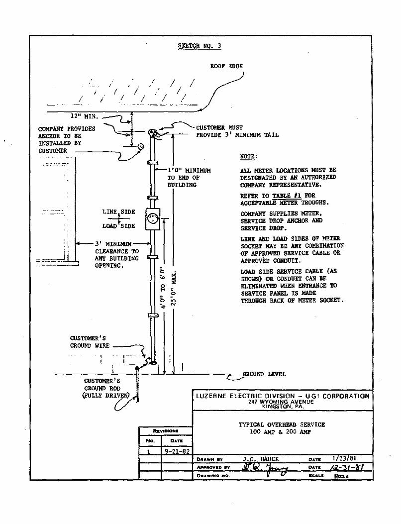
D. The customer will install the attachment anchor at a point on
the building or service support 12" below the service head and such that
the minimum vertical and horizontal clearances indicated below are met.
However, the attachment anchor must never be installed more than 25 feet
above ground level. (See Sketches No. 3 and No. 4.)
12/31/81
vertical: Clearance
(Feet)
a. Roads, streets, alleys, and parking 18'
lots subject to truck traffic.
(Note: Service drops cannot cross
limited access highways.)
Page 4-1
12/31/81
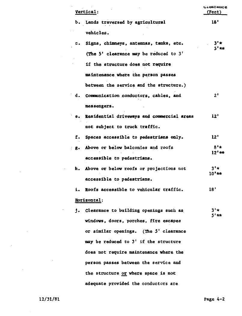
Vertical:
b. Lands traversed by agricultural
vehicles.
c. Signs, chimneys, antennas, tanks, etc.
(The 5' clearance may be reduced to 3 •
if the structure does not require
maintenance where the person passes
between the service and the structure.)
d. Coonuoication .conductors, cables, and
messengers.
..,;.1.e&ra.uce.
(Feet)
18'
3'* S'**
2'
e. B.esidential driveways and commercial areas 12'
not subject to truck traffic.
f. Spaces accessible to pedestrians only.
g. Above or below balconies and roofs
accessible to pedestrians.
h. Above or below roofs or projections not
accessible to pedestrians.
i. llOofs accessible to vehicular traffic.
Horizontal:
j. Clearance to building openings such as
windows, doors, porches, fire escapes
or similar openings. (The 5' clearance
may be reduced to 3' if the structure
does not require maintenance where the
person passes between the service and
the structure .2!: where space is not
adequate provided the coru:luctors are
12'
8'* 12'**
3'* 10'**
18'
3'* 5'**
Page 4-2
insulated to provide sufficient
dielectric to prevent a abort circuit
1n cue of a 110118Dta:ey contact.}
k. Telephone or television aenice drop.
1. R&lnapout, gutter, vent pipes, etc.
JIO'mSa * Oaale servicea suppu:ted by grounied. bare aessenger,
**Open sern,ce oomlw:tora,
u.1.earance (Feet)
2'
l'
For spec1al aituationa or those not COTered above, the lfational
nectr1ca1 Saf'et1 Code will norull.1 prenll. However, the Ooapany should
be contacted regarding tmse instances.
B, Vhe a building 1a of insufficient height to provide adequate
clearances, it 11111 be necessary for the Cuatoaer to furnish, install., and.
maintain a support of aufficient height and strength to obtain the required
clearance. Tb1a 111.ll non,•JJ1 be 1n the fora of a rigid galvanized steel
conduit uat u abcnm 1n Sketch lio, 5.
F, The aenice drop attecbaent -, be aade on a Oust.our 01111ed service
and/or aet«r pole if desil:ed. by the Custoaer, {See Sketchea No, 6 and lo, 7,)
The pole wt be of sufficient height to prov14e aeees&U'J clearances as
specified under paragraJb D above. The CuatOHr v1ll own, install, allCl
aaint.ein tile pole ud. if DeCNaSZ7 provide g\Q'1Dg to Qffaet the pull of the
Coapan1'11 aervice drop. Any instaJ.letion detffllined to be unsafe by the
Coapan)' will not be connected,
G. The Custoaer 11USt provide adeqw.te space on bis propert1 and rlght
of-11&1, if neceaaary, fr011 the Coapan1's nearest distribution line to the
point of delivery'. Thia is neceaaar, for the Coapa.117 to install and uintain
required facll1t1es (poles, tranaforaers, etc.) with the intent of not
exceeding the appzo,,vte service drop lengths as indicated 1n the following
table, 12/31/81 Page 4-J
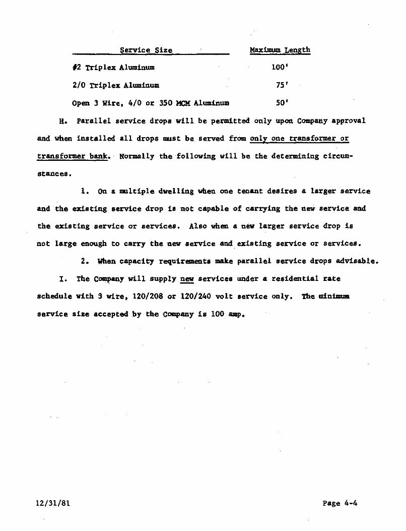
Service Size
#2 Triplex Aluminum
2/0 Triplex Alorminum
Open 3 Wire, 4/0 or 350 MCM Aluminum
Maximum Length
100 1
75'
so•
e. Parallel service drops will be permitted only upon COIRpally approval
and when installed all drops aust be served from only one transformer or
transformer bank.· Normally the following will be the determining circum-
stances.
l. On a JRUltiple dwelling when one tenant desires a larger service
and the existing service drop is not capable of carrying the new service and
the existing service or services. Also when a new larger service drop is
not large enough to carry the new service and. existing service or services.
2. When capacity requirements make parallel service drops advisable.
I. The Company will supply new services under a residential rate ·. -
schedule with 3 wire, 120/208 or 120/240 volt service only. 1.'he minima
service size accepted by the Company is 100 amp.
12/31/81 Page 4-4

SECTION 5 • CCHlEB.ICAL AND INDUSTRIAL SER.VICE • OVERHEAD
Will be completed at a future date.
12/31/81 Page 5-1
SECTION 6 - RESIDENTIAL SERVICE• UNDERGROUND
A. General Information
1. The Customer's service location will be designated by an
authorized Company representative. This point will be the most practical
and accessible from the Company's existing or planned facilities. Normally,
only one service lateral per premises will be provided by the Company. (See
Section 4H.)
2. When underground service is being considered or in areas
where it may be required (underground developments), the customer should
contact the Company before beginning any electrical work. There may be
charges involved for the excess cost of underground service over normal
overhead service. Construction will not begin until the customer pays to
the Company these charges as estimated by the Company.
3. It will be the responsibility of the customer to provide
satisfactory easements, as specified by the Company, for any required Com
pany facilities. Since installation and maintenance of Company equipment
requires ready access, no structure, of any type, will be allowed on Company
easements. If the customer requests the Company to alter its facilities
as originally installed and the Company agrees to do so, it will be at the
expense of the customer.
4. The Customer is responsible for piercing and sealing walls
whenever conduits enter a building. {See Sketch No. 11,)
5. The Company will supply underground services under a resi
dential rate schedule with 3 wire, 120/208 or 120/240 volt service only.
The minimum service size accepted by the Company is 100 amp.
B. Underground Developments
1. For residential developments covered under the Pennsylvania
Public Utility Order I.D. No. 99, the underground installation will be made
12/31/81 page 6-1
in accordance with the Company's Electric Service Tariff Rule No. 18.
Before finalizing plans for the development of property as residential
dwellings, the Customer should contact the Company.
In general, all distribution, service, and street lighting
lines installed in a development covered by Rule No. 18 shall be installed
underground and shall be owned and maintained by the Company. The
installation may be performed by the Company or by such other entity as
the Company may authorize.
2. All service entrance equipment shall be furnished,
installed, and maintained by the Customer as specified on the appropriate
Sketch No. 8, No. 9, or No. 11. In the special cases indicated on Sketch
No. 11 the Company will supply the current transformer and meter trough
for installation by the Customer.
3. When the Company elects to install direct burial cable and
the Customer plans to install a sidewalk, driveway, or patio in the area
where the underground service is to be located, it will be the Customer's
responsibility to install conduit as specified by the Company for
protection and ease of maintenance of the service wire. Acceptable
conduits are electrical grade PVC Schedule 40, threaded galvanized rigid
and intermediate steel. Ownership of all such conduits installed by the
Customer on the line side of the point of delivery and not located in, on
or under buildings shall vest in the Company free-of-charge. The Company
will thereafter maintain these facilities.
4. Various agreements are utilized with developers of
residential areas for trenching and backfilling. A Customer should
contact the Company if any doubt exists as to where this responsibility
lies.
02/24/92 Page 6-2
C. Underground Service from Overhead Secondary Facilities - Company
Installed
If a Customer who would normally be supplied from the Company's
overhead distribution system, desires the service wires across his
property to be installed underground, the Company will install, own, and
maintain an underground service lateral from a Company pole on or adjacent
to the Customer's property to the point of delivery. The following
conditions will apply.
1. The Customer must pay to the Company its estimated excess
cost of underground service over the estimated cost of normal overhead
construction, plus any right-of-way or permit fees incurred by the Company.
2. Trenching and backfilling must be performed by the Customer
in accordance with Company specifications. (See Sketch No. 12.)
3. Service entrance requirements, conduit specifications, and
related items will be as covered under Section 6-B-2, 3, and 4 above and
Sketches No. 8, No. 9, and No. 11.
D. Underground Service from Overhead Secondary Facilities - Customer
Installed
As an alternative to Company installed facilities, the Customer may
furnish, install, and maintain his own underground service. The service
conduit may be installed on a pole or support belonging to the Customer or
a Company owned pole. (Service entrance equipment, meter trough,
disconnect, etc., will not be permitted on a Company pole.)
When a Customer pole or service support is utilized, the Company will
attach its overhead service drop to this structure and make the connection
to the Customer's service conductors at this point. The Company's
facilities are then a standard overhead service.
02/2ll/92 Page 6-3
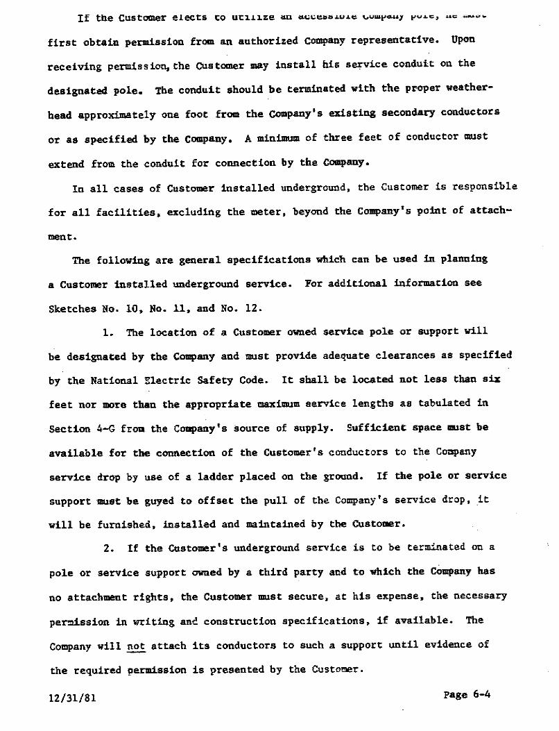
first obtain permission from an authorized Company representative. Upon
receiving permission, the customer may install his service conduit on the
designated pole. The conduit should be terminated with the proper weather
head approximately one foot from the company's existing secondary conductors
or as specified by the Company, A minimum of three feet of conductor must
extend from the conduit for connection by the Company.
In all cases of Customer installed underground, the Customer is responsible
for all facilities, excluding the meter, beyond the Company's point of attach
ment.
The following are general specifications which can be used in planning
a Customer installed underground service. For additional information see
Sketches No. 10, No. 11, and No. 12.
1. The location of a Customer owned service pole or support will
be designated by the Company and ?DUSt provide adequate clearances as specified
by the National Electric Safety Code. It shall be located not less than six
feet nor more than the appropriate maximum service lengths as tabulated in
Section 4-G froa the Coapany 's source of su11ply. Sufficient s11ace must be
available for the connection of the Customer's conductors to the Company
service drop by use of a ladder placed on the ground. If the pole or service
support 11111st be guyed to offset the pull of the Company's service drop, it
will be furnished, installed and maintained by the Customer.
2. If the Customer's underground service is to be terminated on a
pole or service support owned by a third party and to which the Company has
no attachment rights, the Customer 11111st secure, at his expense, the necessary
per.:u.ssion in writing anc construction specifications, if available. The
Company will~ attach its conductors to such a support until evidence of
the required permission is presented by the Customer.
12/31/81 Page 6-4
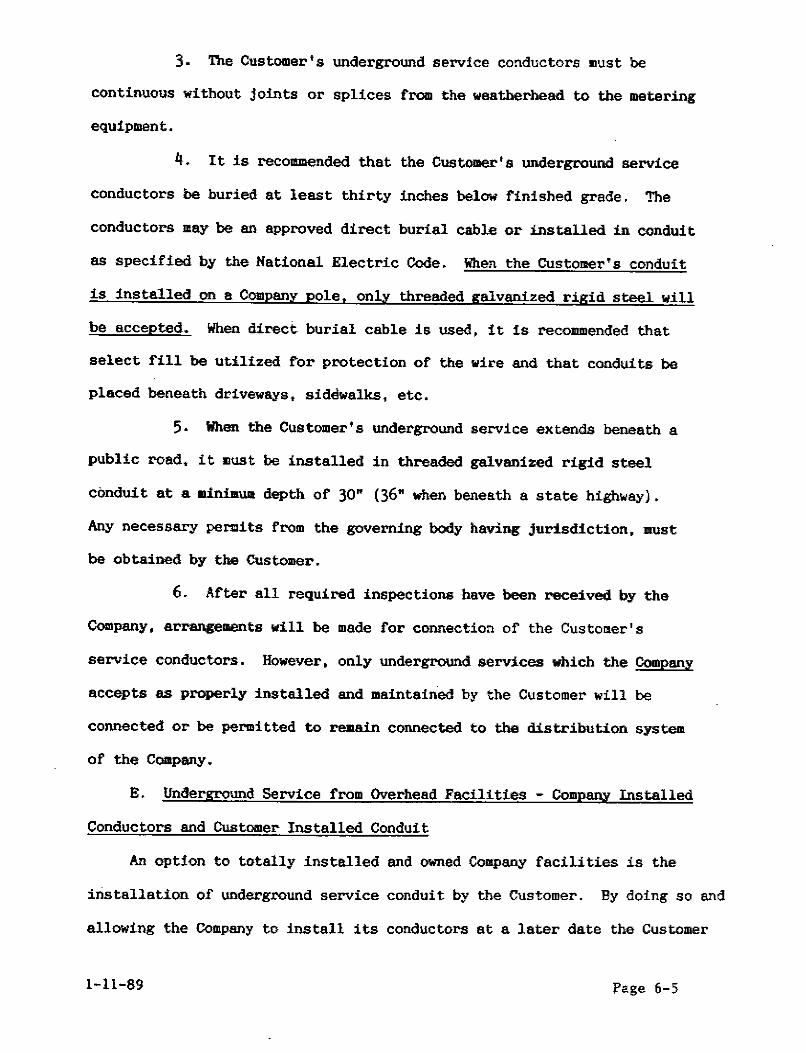
3. The Customer's underground service conductors must be
continuous without joints or splices from the weatherhead to the metering
equipment.
4. It is recommended that the Customer's underground service
conductors be buried at least thirty inches below finished grade. The
conductors may be an approved direct burial cable or installed in conduit
as specified by the National Electric Code. When the Customer's conduit
is installed on a Company pole, only threaded galvanized rigid steel will
be accepted. When direct burial cable is used, it is recommended that
select fill be utilized for protection of the wire and that conduits be
placed beneath driveways, sidewalks, etc.
5. When the Customer's underground service extends beneath a
public road, it llll5t be installed in threaded galvanized rigid steel
conduit at a llinimwa depth of 30n (36n when beneath a state highway).
Any necessary permits from the governing body having jurisdiction, must
be obtained by the Customer.
6. After all required inspections have been received by the
Company, arrangements will be made for connection of the Customer's
service conductors. However, only underground services which the Company
accepts as properly installed and maintained by the Customer will be
connected or be permitted to re11.ain connected to the distribution system
of the Company.
E. Underground Service from Overhead Facilities - Company Installed
Conductors and Customer Installed Conduit
An option to totally installed and owned Company facilities is the
installation of underground service conduit by the Customer. By doing so and
allowing the Company to install its conductors at a later date the Customer
l-ll-89 l'age 6-5
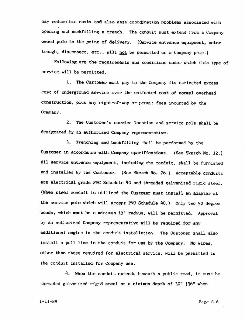
may reduce his costs and also ease coordination problems associated with
opening and backfilling a trench. The conduit must extend from a Company
owned pole to the point of delivery. (Service entrance equipment, meter
trough, disconnect, etc., will not be permitted on a Company pole.)
Following are the requirements and conditions under which this type of
service will be permitted.
1. Toe Customer must pay to the·Company its estimated excess
cost of underground service over the estimated cost of normal overhead
construction, plus any right-of-way or permit fees incurred by the
Company.
2. Toe Customer's service location and service pole shall be
designated by an authorized Company representative.
3. Trenching and backfilling shall be performed by the
Customer in accordance with Company specifications. (See Sketch No. 12.)
All service entrance equipment, including the conduit, shall be furnished
and installed by the Customer. {See Sketch No. 26.) Acceptable conduits
are electrical grade PVC Schedule 40 and threaded galvanized rigid steel.
(When steel conduit is utilized the Customer must install an adapter at
the service pole which will accept PVC Schedule 40.) Only two 90 degree
bends, which must be a minimum 13" radius, will be permitted. Approval
by an authorized Company representative will be required for any
additional angles in the conduit installation. The Customer shall also
install a pull line in the conduit for use by the Company. No wires,
other than those required for electrical service, will be permitted in
the conduit installed for Company use.
4. When the conduit extends beneath a public road, it must be
threaded galvanized rigid steel at a minimUll!. depth of 30n (36n when
1-11-89 Page 6-6
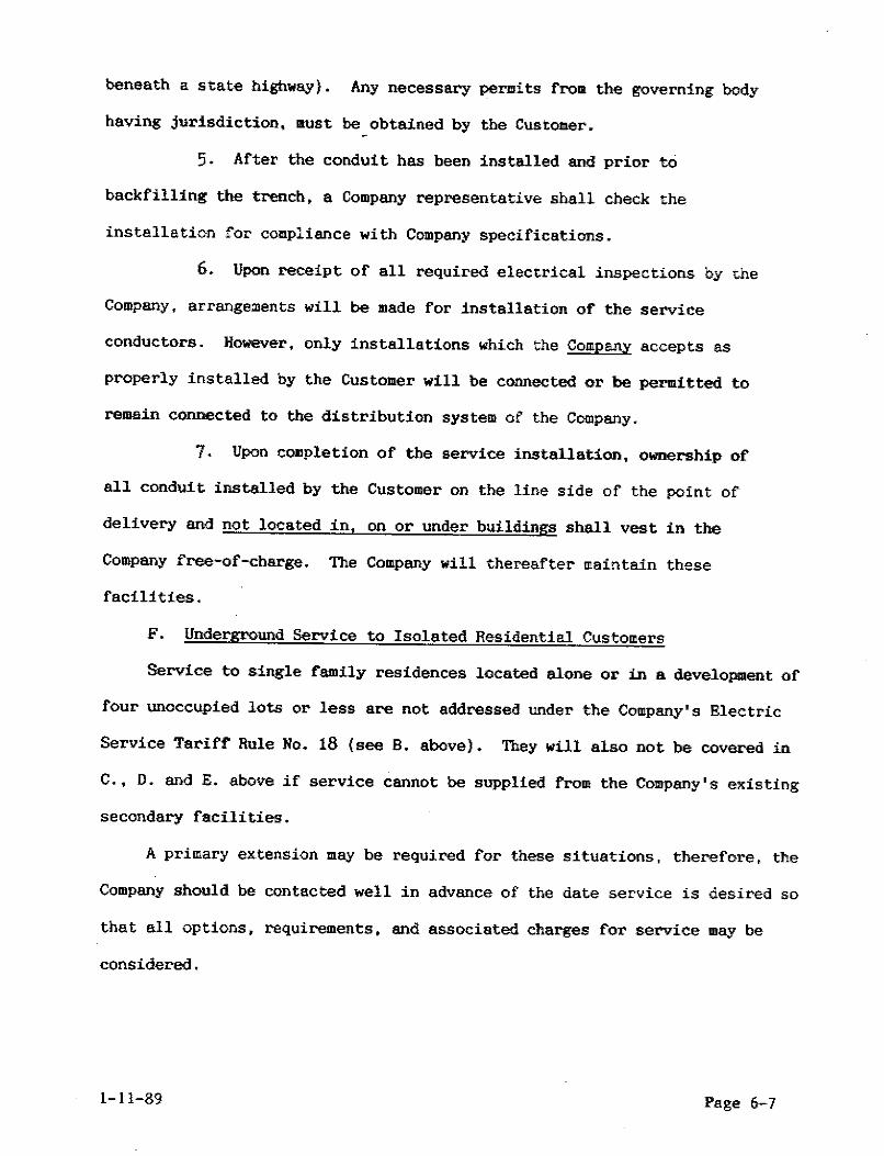
beneath a state highway). Any necessary permits from the governing body
having jurisdiction, must be obtained by the Customer.
5. After the conduit has been installed and prior to
backfilling the trench, a Company representative shall check the
installation for compliance with Company specifications.
6. Upon receipt of all required electrical inspections by the
Company, arrangements will be made for installation of the service
conductors. However, only installations which the Company accepts as
properly installed by the Customer will be connected or be permitted to
remain connected to the distribution system of the Company.
7. Upon completion of the service installation, ownership of
all conduit installed by the Customer on the line side of the point of
delivery and not located in, on or under buildings shall vest in the
Company free-of-charge. The Company will thereafter maintain these
facilities.
F. Underground Service to Isolated Residential Customers
Service to single family residences located alone or in a development of
four unoccupied lots or less are not addressed under the Company's Electric
Service Tariff Rule No. 18 (see B. above). They will also not be covered in
C., D. and E. above if service cannot be supplied from the Company's existing
secondary facilities.
A primary extension may be required for these situations, therefore, the
Company should be contacted well in advance of the date service is desired so
that all options, requirements, and associated charges for service may be
considered.
1-11-89 Page 6-7

SECTION 7 - C<IIHER.CIAL AND nmusnuAL SEllVICE - UNDERGRCIJND
Will be completed at a future date.
12/31/81 Page 7-1
SECTION 8 - MOBILE HOME SERVICES
A. l'he Company will supply either overhead or underground service to a
permanently sited mobile home through the Customer's service entrance equipment,
mounted adjacent to the mobile home. The service entrance equipment cannot be
mounted on the mobile home or its foundation. Double wide units, assembled
and placed on a permanent foundation, which have -tal floor joists, are also
considered mobile homes and must have the service entrance equipment mounted
adjacent to the structure, Sketches No. 13 and No. 14 represent typical mobile
home installations. As with any service, the location will be given by an
authorized Company representative.
:B. A mobile home is considered permanent if a permagent foundation, or
pillars, are used to support the mobile home, permanent water and sanitary
facilities are installed, and the occupant of the mobile home owns the property
on which it is located, If a mobile home is determined by the Company to be
permanent, service will be extended as to any permanent dwelling with the
exception of the location of the service entrance equipment as discussed in
paragraph A above.
c. If a mobile home is determined by the Company to be temporary, service
will be extended overhead a maximum of 100 feet. Company installed underground
facilities are not available in this situation.
D, When the Cust=r's mobile ho- is located within a mobile home park,
the park owner is usually responsible for contacting the Company regarding the
extension of facilities for service. If an extension is to be made to five or
more lots in a mobile home park, underground service will be installed in
accordance with Rule No. 18 of the Company's Electric Service Tariff. The park
owner should contact the Company regarding the location of facilities and charges
associated with the underground installation. (See Section 6-A of this manual
for more information.)
9/21/82 Page 8-1
E. The grounding conductor and service entrance equipment shall be
grounded in accordance with the latest edition of the Rational Electrical
Code.
12/31/81 Page 8-2
SECTION 9 - METERING - GENEBAL
A. The Customer shall provide, without charge to the Company, space to
accommodate the Company's meters and associated equipment at the point of
delivery or nearest suitable location designated by an authorized Company
representative. 'l'he area chosen shall be readily accessible to Company
personnel at a1i reasonable times for reading, testing, and replacement of
equipment.
B. 'l'he capacity and type of meter installation needed to accommodate
the CUatomer's load and type of service shall be determined by the Company.
c. The customer uaist install the meter trough or panel at the designated
location approximately 4' to 6' above finished ground or floor level. It
shall be installed level and plumb and securely fastened to the structure
or other support not subject to vibration. Locations will be chosen so
that the meter is protected from mechanical damage and does not interfere
with pedestrian or vehicular traffic.
D. Meters shall be installed, removed, and/or relocated only by autho
rized employees of the Company.
E. Metered and unmetered conductors are not to be installed in the
same conduit or raceway.
F. Meter troughs, transformer cabinets or other metering equipment are
not to be used as junction boxes.
G. The Company's standard practice is to locate all meters outdoors.
Indoor locations will be permitted only when approval, in writing, is
obtained from the Company. An approved indoor location must be readily
accessible and not located where excessive heat or moisture may develop,
acid fumes are present, or unusual amounts of dust exist.
12/31/81 Page 9-1

a. A 4' minimum clearance. measured from the wall on which the meter
trough and/or instrument transformer cabinet are lllOWlted, must be provided
directly in front of these devices. The installation must also not inter
fer-e with the opening of doors or windows.
12/31/81 Page 9-2
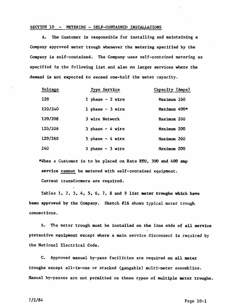
SECTION 10 - METERING - SELF-CONTAINED INSTALLATIONS
A. The Customer is responsible for installing and maintaining a
Company approved meter trough whenever the metering specified by the
Company is self-contained, The Company uses self-contained metering as
specified in the following list and also on larger services where the
demand is not expected to exceed one-half the meter capacity.
Voltage Type Service Capacity (Amps)
120 1 phase - 2 wire Maximum 100
120/240 1 phase - 3 wire Maximum 400*
120/208 3 wire Network Maximum 200
120/208 3 phase - 4 wire Maximum 200
120/240 3 phase - 4 wire Maximum 200
240 3 phase - 3 wire Maximum 200
*When a Customer is to be placed on Rate RTU, 300 and 400 amp
service cannot be metered with self-contained equipment.
Current transformers are required,
Tables 1, 2, 3, 4, 5, 6, 7, 8 and 9 list meter troughs which have
been approved by the Company, Sketch #16 shows typical meter trough.
connections.
B. The meter trough must be inst,alled on the line side of all service
protective equipment except where a main service disconnect is required by
the National Electrical Code.
C, Approved manual by-pass facilities are required on all meter
troughs except all-in-one or stacked {gangable) multi-meter assemblies.
Manual by-passes are not permitted on these types of multiple meter troughs.
7/2/84 Page 10-1
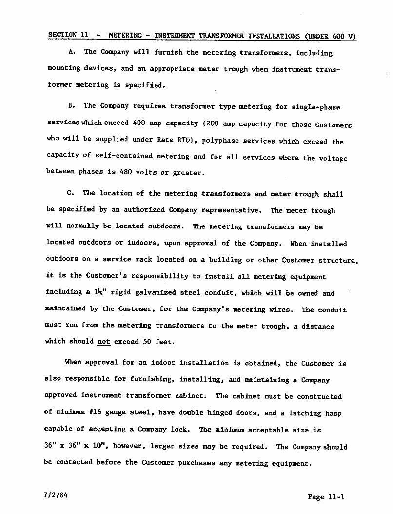
SECTION 11 METERING - INSTRUMENT TRANSFORMER INSTALLATIONS (UNDER 600 V)
A. The Company will furnish the metering transformers, including
mounting devices, and an appropriate meter trough when instrument trans
former metering is specified.
B. The Company requires transformer type metering for single-phase
services which exceed 400 amp capacity (200 amp capacity for those Customers
who will be supplied under Rate RTU), polyphase services which exceed the
capacity of self-contained metering and for all services where the voltage
between phases is 480 volts or greater.
C. The location of the metering ·transformers and meter trough shall
be specified by an authorized Company representative. The meter trough
will normally be located outdoors. The metering transformers may be
located outdoors or indoors, upon approval of the Company. When installed
outdoors on a service rack located on a building or other Customer structure,
it is the Customer's responsibility to install all metering equipment
including a lli;" rigid galvanized steel conduit, which will be owned and
maintained by the Customer, for the Company's metering wires. The conduit
must run from the metering transformers to the meter trough, a distance
which should not exceed 50 feet.
When approval for an indoor installation is obtained, the Customer is
also responsible for furnishing, installing, and maintaining a Company
approved instrument transformer cabinet. The cabinet must be constructed
of minimum #16 gauge steel, have double hinged doors, and a latching hasp
capable of accepting a Co111pany lock. The minimum acceptable size is
36" x 36" x 10", however, larger sizes may be required. The Company should
be contacted before the Customer purchases any metering equipment.
7/2/84 Page 11-1
D. If the metering transformers and meter trough are to be installed
on a Company owned pole or structure, the Company will furnish, install
and maintain all metering equipment,
E. When a three-phase padmounted type transformer is utilized to
serve a Customer, the metering transformers are normally installed, by the
Company, in the secondary compartment of the transformer, The Customer is
responsible for installing the meter trough at the specified location. It
is also the Customer's responsibility to furnish, install and maintain a
1¼" rigid galvanized steel conduit from the meter trough to the secondary
compartment of the padmount transformer.
F, Metering transformers must be installed on the line side of all
service protective equipment in the manner specified by the Company unless
the location of the meters mutually agreed upon is remote from the service
entrance and/or where the National Electrical Code requires the installation
of a main service disconnect ahead of the metering equipment,
G. Sketches 11, 17, 18, 1~, 20, 21, 22, 23, 24 and 25 illustrate
typical instrument transformer installations.
7/2/84 Page 11-2
SECllON 12 - METERIHG - MIJLTI•METER INSTALLATIONS
A. Meters for all customers in a multiple occupancy building must be
grouped at one location which is readily accessible. In large buildings it
may be desirable to establish several metering points and group meters for
CUstomers by floors or sections of the building. In this situation, the
customer is responsible for installing a cOIIIIIIOll service entrance for the
building with an individual main frOlll the service protective equipment to
each group metering point. The meter installation at each location is the
same as any other group installation. (See Sketch No. 15 and Section LO-c
above.)
B. The meter trough and sub-service disconnecting equipment for each
customer in a multi-meter installation shall be clearly and permanently marked
by the owner designating the apartment numbers, lot number, etc., that it
supplies.
c. Meter troughs for 1111lti-meter installations may be installed either
as horizontal multiple meter troughs with built-in bussing (Sketch No. 15) or
as individual meter troughs preceded by a sealable horizontal wire trough.
Where a wire trough is installed, all taps from the common service entrance
conductors to the metering equipment for eacb aub-service shall be made in
the wire trough by the customer.
Approved factory assembled multiple meter trough units are listed in
Tables 3, 4, S, and 6.
, .,, ,.,, :a, n .. --. 1"'t_1

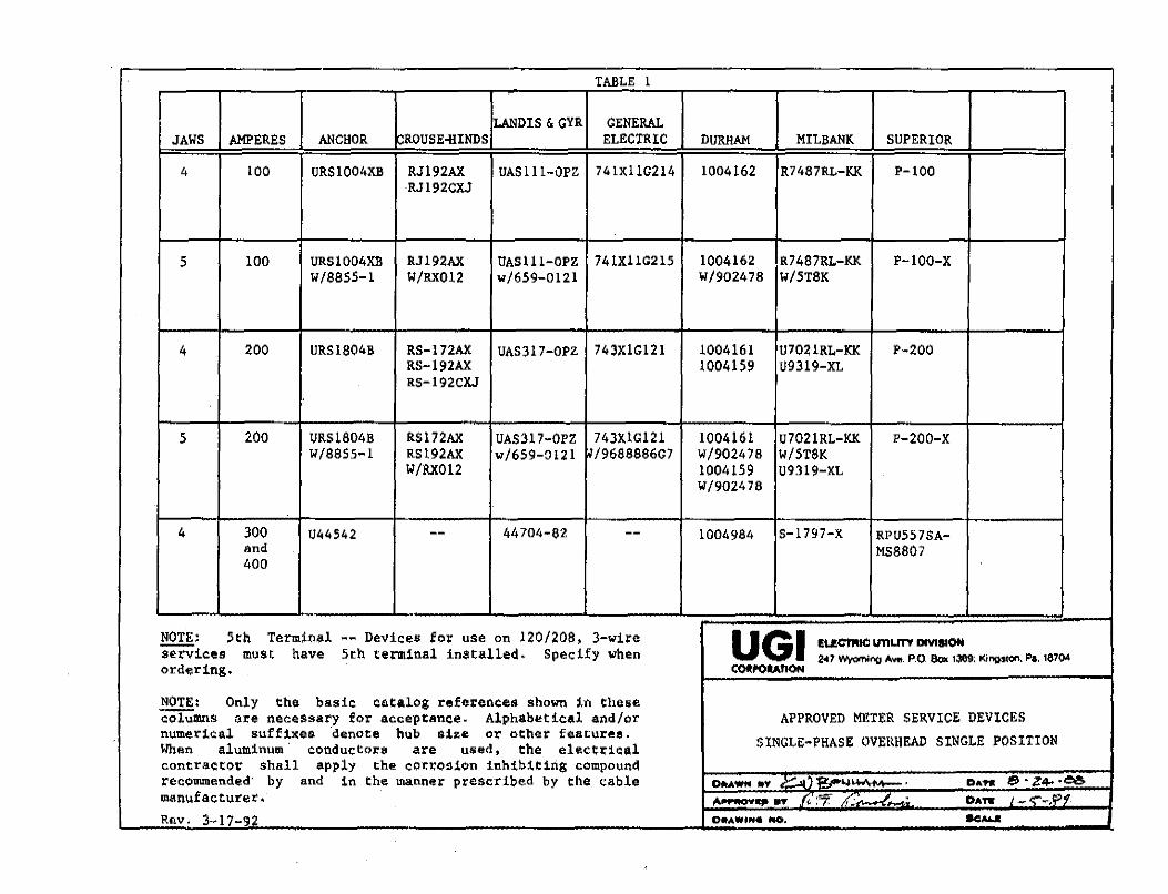
TABLE l
LANDIS & GYR GENERAL JAWS AMPERES ANCHOR CROUSE-HINDS ELECTRIC DURHAM MILBANK SUPERIOR
4 100 URSlOOl1XB RJ192AX UASlll-OPZ 741XllG214 1004162 R7487RL-KK P-100 RJ192CXJ
5 100 URS1004XB RJ192AX UAS1ll-OPZ 741XllG215 1004162 R7487l\L-KK P-100-X W/8855-1 W/l\X012 w/659-0121 W/902478 W/5T8K
4 200 URS1804B l\S-l 72AX UAS317-0PZ 743X1Gl21 1004161 U7021RL-KK P-200 l\S-192AX 1004159 09319-XL RS-192CXJ
5 200 URS1804B RS172AX UAS317-0PZ 743XlG121 1004161 U7021RL-KK P-200-X W/8855-1 RS192AX w/659-:)121 il/968888607 W/902478 W/STSK
W/RX012 1004159 09319-XL W/902478
4 300 044542 -- 44704-82 -- 1004984 S-1797-X RPU557SA-and MS8807 400
NOTE: 5th Terminal -- Devices for use on 120/208, 3-wire u GI EIJ!cn,IC U11LITI' DMSl()f,I ~ices must have 5th terminal installed. Specify when 2<17 -og Ave. P.Q !lox 1389: l(Jogs,on. Po. 1870, ordering. COl!l'OlAIION
NOTE: Only the bade catalog references shown in these columns are necessary for acceptance. Alphabetical and/or APPROVED METER SEl\VICE DEVICES numerical suff:lxes denote hub size or other featur~e. SINGLE-PHASE OVEl\HEAD SINGLE POSITION When aluminum conductors are usedt the electrical contractor shall apply the ~ori:osion inhtbtt1ng compound recommended· by and 1n the manner prescribed by the cable OAAWN •v r..ia·t~l,,l~, Due ~-z4-.eet, manufacturer, "'""""''" .... /, :";: ;(:
H • O•nr , - c:--,!P?' Rav. 3~17-92 D•AW•H• fliO, .., .....
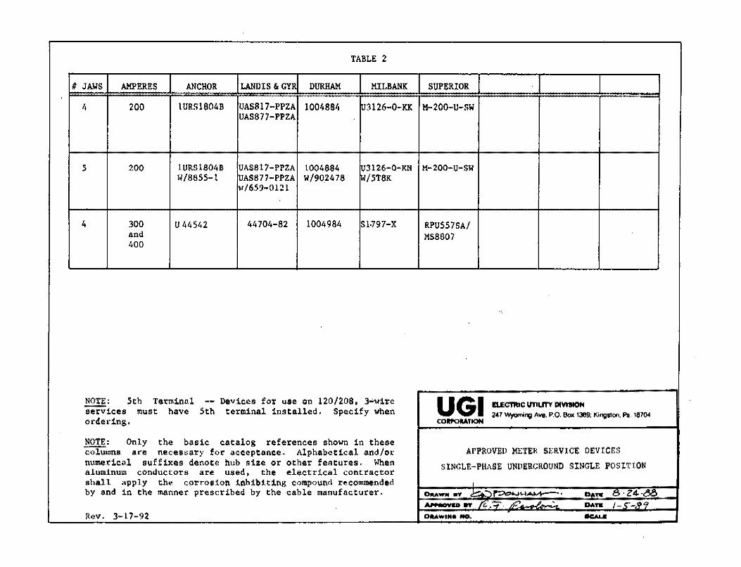
TABLE 2
II JAWS AMPERES ANCHOR LANDIS & GYR DURHAM MILBANK SUPERIOR
4 200 1URS1804B UAS817-PPZA 1004884 03126-0-KK M-200-U-SW UAS877-PPZA
5 200 1URS1804B UAS817-PPZA 1004884 lr.r3126-0-KN M-200-u-sw W/8855-1 UAS877-PPZA W/90.2478 IW/5T8K
w/659-0121
4 300 U 44542 44704-82 1004984 Sl-797-X RPU557SA/ and MS8807 400
NOTE: 5th Tei:111inal -- Devices for use on 120/208, 3~wire u GI EI.ECTRIC UTILITY PMIION iierii'ices must have 5th terminal installed, Specify when 2,1 w,,,m;ng Ave, P.O. Box 1389: Kingston. Pa. 16704 ordering. CORl'OIIATION
NOTE: Only . the basic catalog references shown in these ~mns are necessary for acceptance .. Alphabetical and/or APPROVED METER SERVICE DEVICES numerical suffixes denote hub size or other features, When SlNGLE-PHASE UNDERGROUND SINGLE POSITION aluminum conductors are used. the electrical contractor shall apply the corrosion inhibiting compound recommended I
by and in the manner prescribed by the cable manufacturer. DIIIIAWN 11V Joio"'....t..""\~t,...I~, ., .. .,. c. Z4.,&!:', ~- .,. re..-:;-. n.- • . .,.. .. /-_, __ .,,.,
Rev. 3-17-92 0111.Ailll'IH:e NO. . ..,..._.
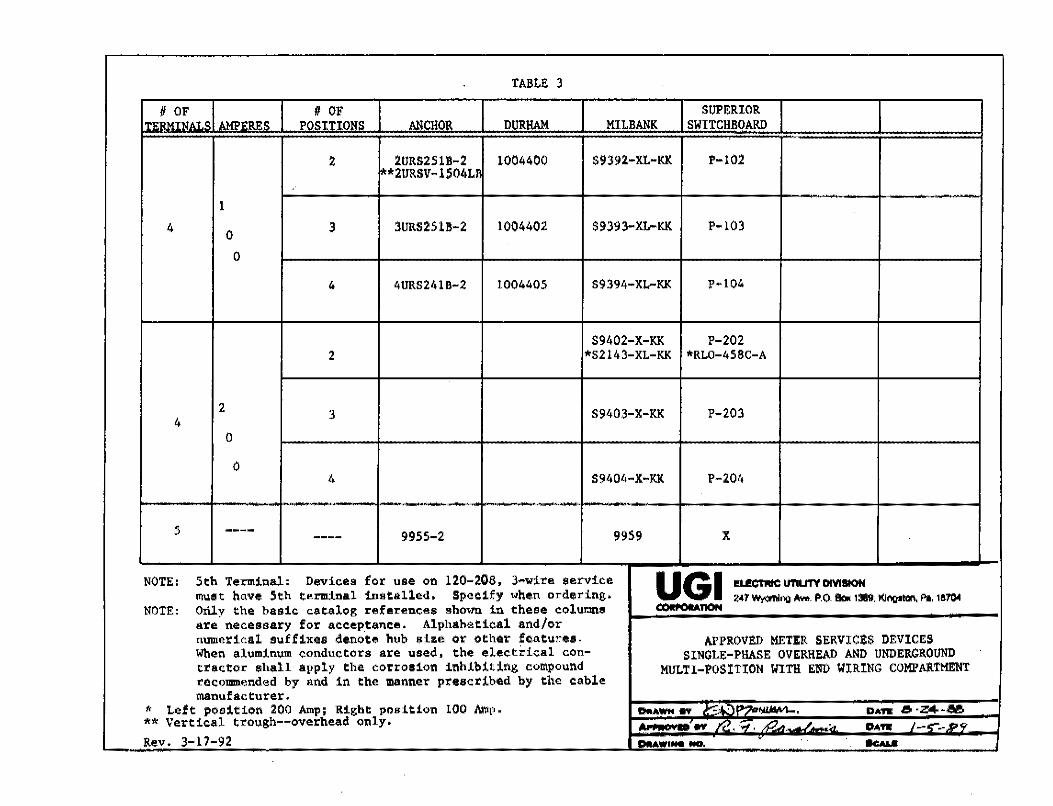
TABLE 3
II OF # OF SUPERIOR , ' o, O AM1>1'RES POSITIONS ANCHOR DURHAM MILBANK SWITCHBOARD
2 2URS251B-2 1004400 $9392-XL-KK P-102 **2URSV-15011Ll
l
4 0 3 3URS251B-2 1004402 $9393-XL-KK P-103
0
4 4URS241B-2 1004405 S9394-XL-KK P~l04
S9402-X-KK P-202 2 *S2143-XL-KK *RL0-458C-A
2 3 S9403-X-KK P-203
4 0
0 4 S9404-X-KK P-204
5 ---- 9955-2 9959 X ----NOTE: 5th Te=inal: Devices for use on 120-208, 3-wire service u GI l!U!CTNC UTIUTV DMIION lllUSt have 5th terminal installed, Specify when ordering, i,r w,.,m;ng -· P.O. ea. 1389; l(Jngttoo. Pl. 18104 NOTE: Only the basic catalog references sho,rn in these eolur,ns C(Nll'OU.nCIN
are necessary for aeeep.tance, Alphah<!!tical and/or numerical suffixes denote hub size or other features. APPROVED METER SERVICES DEVICES When aluminum conductors are used, the electrical eon- SINGLE-PHASE OVERHEAD AND UNDERGROUND tractor shall apply the corrosion inhibiting compound MULTI-POSITION WITH ENU WIRING COMPARTMENT recommended by and in the manner prescribed by the cable manufacturer.
* Left position 200 Amp; Right position LOO Amp. DtlAWN ff 1"""~·)P70~, DAft &•Z4•A'!o ** Vertical trough--overhesd only, Al IIIIIIIOI\IIO .,, /"c!., . .,, , .,("7.,. • DAft /-,;- ... 1>q
Rev, 3-17-92 ~WINNO, . -
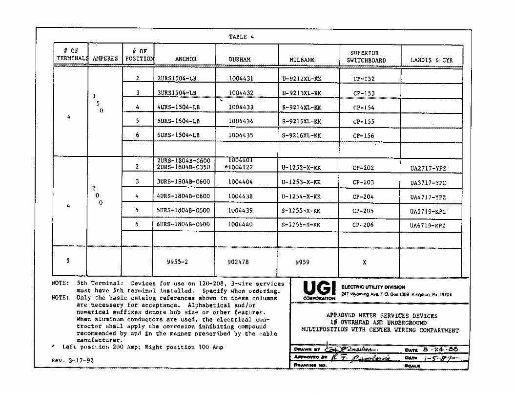
TABLE 4
II OF II OF SUPERIOR TERMINAL AMPCRES POSITIO! ANCHOR OURHAM MILBANK SWITCHBOARD LA.'lDlS & GYR
2 2URS1504-Lll 1004431 U-92 l 2XL-KK CP-152
1 3 3URS1504-LB 1004432 U-9213XL-KK CP-153 ~
5 4 4URS-1504-LB 1004433 S-9214XL-KI< CP-154 0 4
5 SURS-1504-LB 1004434 S-9215XL-KK CP-155
6 6URS-1504-LB 1004435 $-9216XL-KK CP-156 .
2URS-1804B-C600 l•" " 2 2URS-l804B-C350 *1004122 U-1252-X-KK CP~202 UA2717-YPZ
3 3URS-1804B-C600 1004404 U-1253-X-KK CP-W3 UA3717-YP:: 2 0 4 4URS-l804B-C600 1004438 U-12~4-X-KK CP-204 UA4 717-YPZ
4 0 5 5UR$-l804B-C600 lU04439 S-1255-X-KK CP-205 UA5719-KPZ
6 6URS-1804B-C600 1004440 S-1256-X-KK CP-206 UA6719-KPZ
5 ~955-2 902478 ~959 X
NOTE: 5th Terminal: Devices for use on 120-208, 3-wire s,ervicru UGI ELECTR1c unutY DIVISION must have 5th terminal installed. Specify when ordering. 2<17 Wyoming Ave. P.0 8oK 1389: K,ng•too, Pa. 1e104 NOTE: Only the basic c~talog references shown in these columns COll'OUTIQH
are necessary for acceptance, Alphabetical and/or numerical suffixes denote hub size or other features. APPROVED METER SERVICES DEVICES When aluminum conductors are used, the electrical con- 10 OVERHEAD AND UNDERGROUND tractor shall apply the corrosion inhibiting compound MULTIPOSITION WITH CENTER WIRING COMPARTMENT reconunended by and in the manner prescribed by the cable manufacturer. •
* Left position 200 Amp; Right position 100 Amp DflAWN rt ....... I ....t.M-, DA111 & "~4, •.!>O Nr•av• n n.: :::;:: fl ,
DAn J-,-J?9,--.- · Rev. 3~17-92 DAAWtM• NO.
. .......
'IAIILE 5
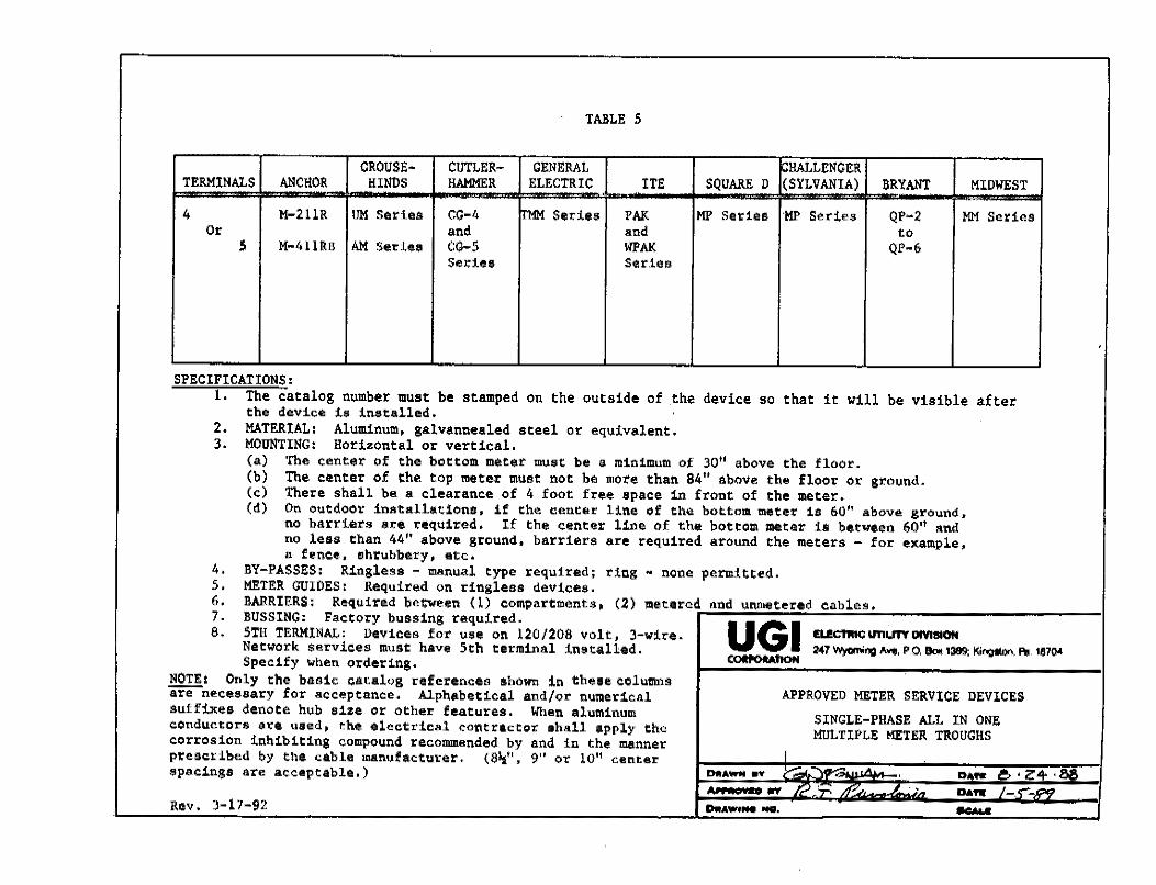
CROUSE:- CUTLER- GENERAL :HALL£NGllR TERMINALS ANC!!Oll HINDS HAMMER ELECTRIC IT£ SQUARED (SYLVANIA) llRYANT MIDWEST
4 M-2llR UM Series CG-4 trMM Series PAK MP Series ·MP Series QP-2 MM Series Or and and to
5 M-411RB AM $er:l.u CG-5 WPAK QP-6 Sedu Seriea
SPECIFICATIONS: 1. The catalog number must be stamped on the outside of .the device so that it will be visible after
the device is installed. 2. MATERIAL: Aluminum, galvannealed steel or equivalent. 3. MOUNTING: Horizontal or vertical.
(a) The center of the bottom meter must be a minimum of 30" above the floor. (b) The center of the top meter must not be more than 84" above the floor or ground. (c) There shall be a clearance of 4 foot free space in front of the meter. (d) On outdoor installations, if the center line of the bottom meter is 60'' above ground,
no barriers are required. If the center line of the bottom meter is between 60'1 and no less than 44" above ground, barrier$ are required around the meters - for example, a fence, shrubbery, etc,
4. BY-PASSES: Ringless - manual type required; ring M none permitted. 5. METER GUIDES: Required on ringless devices, 6. BARRIERS: Required between (1) compartments, (2) metered and unmetered cables. 7. BUSSING: Factory bussing required.
UGI 8. 5TH TERMINAL: Devices for use on 120/208 volt, 3-wire. IU!CTIIIC unun DM1110H Network services must have 5th terminal instal~ed. 2'17 Wyoming """' P,0, 11oo< 1389; King_, Po. 18704 Specify when ordering. --NOTE: Only the basic catalog references shown in these columns
APPROVED METER SERVICE DEVICES are necessary for acceptance. Alphabetical and/or numerical suffixes denote hub size or other features. When aluminum
SINGLE-PHASE ALL IN ONE conductors are used, the electrical contractor shall apply the MULTIPLE METER TROUGHS corrosion inhibiting compound recollllll8nded by and in the manner
prescribed by the cable manufacturer. (8¼,u, 911 or 10" center I
spacings are acceptable.) INAW1ill rt ' .u•A• • D•ft 6 •Z4 ·88 Arr•olltWO.., ,_,,, • u .......
, . .,,. .. !-.,-Rev. 3-17-92 0.AWt ... NIii. -
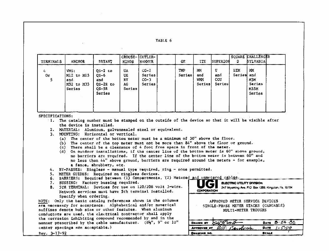
TABLE 6
CROUSE-CUTLER- SQUARE: CHALLENG R Tl!RMlNALS ANCHOR BRYANT HlNOS HAMMtR GE ITE SUPERIO! D SYLVANIA
4 VMS; QS-2 to UA CG-2 TMP MM u EZM MM Or Ml2 to Ml5 QS-6 UE Series Series and and Seri•n and
5 and and RY CG-3 WMM CCU M3M M32 to M35 QS-2R to AG Series Series Sertea Series Series QS-SR Series M35M
Series Series
SPECIFICATIONS: 1. The catalog number must be stamped on the outside of the device so that it will be visible after
the device is installed. 2. MATERIAL: Aluminum, galvannealed steel or equivalent. 3. MOUNTING: Horizontal or vertical.
(a) The center of the bottom meter must bes minimum of 30" above the floor. (b) The center of the top meter must not be more than 84" above the floor or ground, (c) There sha11 be a clea~ance of 4 foot free $pace in front of th• meter. (d) On outdoor installations. if the center line of the bottom meter is 60 11 above ground,
no barriers are required, If the center line of the bottom meter is between 60" and no less than 44" above ground, barriers are required around the meters - for example, a fence, shrubbery, etc,
4, BY-PASSES: Ringless - manual type required, ring - none permitted, 5. METER GUIDES: Required on ringless devices, · 6. BARRIERS: Required between (1) Compartments, (2) Metered and unmctarcd c3blcs. 7. BUSSING: Factory bussing required. u G I EU!CTl'IIC UTILITY OMS40t, 8. 5TH TERMINAL: Devices for use on 120/208 volt 3-wire. 2'17 W/<lffllng /\w:. P,0 8ol< 138ll; King'1on. Po. 18704
Network services must have 5th terminal installed. COlll'Ol!AtlON
Specify when ordering. NOTE: Only the basic catalog references shown in the columns APPROVED Ml!TER SERVICE DEVICES ~necessary for acceptance. Alphabetical and/or numerical SINGLE-PHASE Ml!TER STACKS (GANGABLE) suffixes denote hub size or other features. When aluminum MULTI•Ml!TER TROUGHS conductors are used, the electrical contractor shall apply the corrosion inhibiting compound recommended by and in the • manner prescribed by the cable manufacturer. (8½", 9" or 10" DIii.AWN av ,. - DATIi .e, · Z:4 ,61',
center spacings are acceptable.) ..__ ... rt o:. ~. " . DATIi /-,-=
Rev. 3~17-92 o .. ,.,., .... .... . ., ..... '
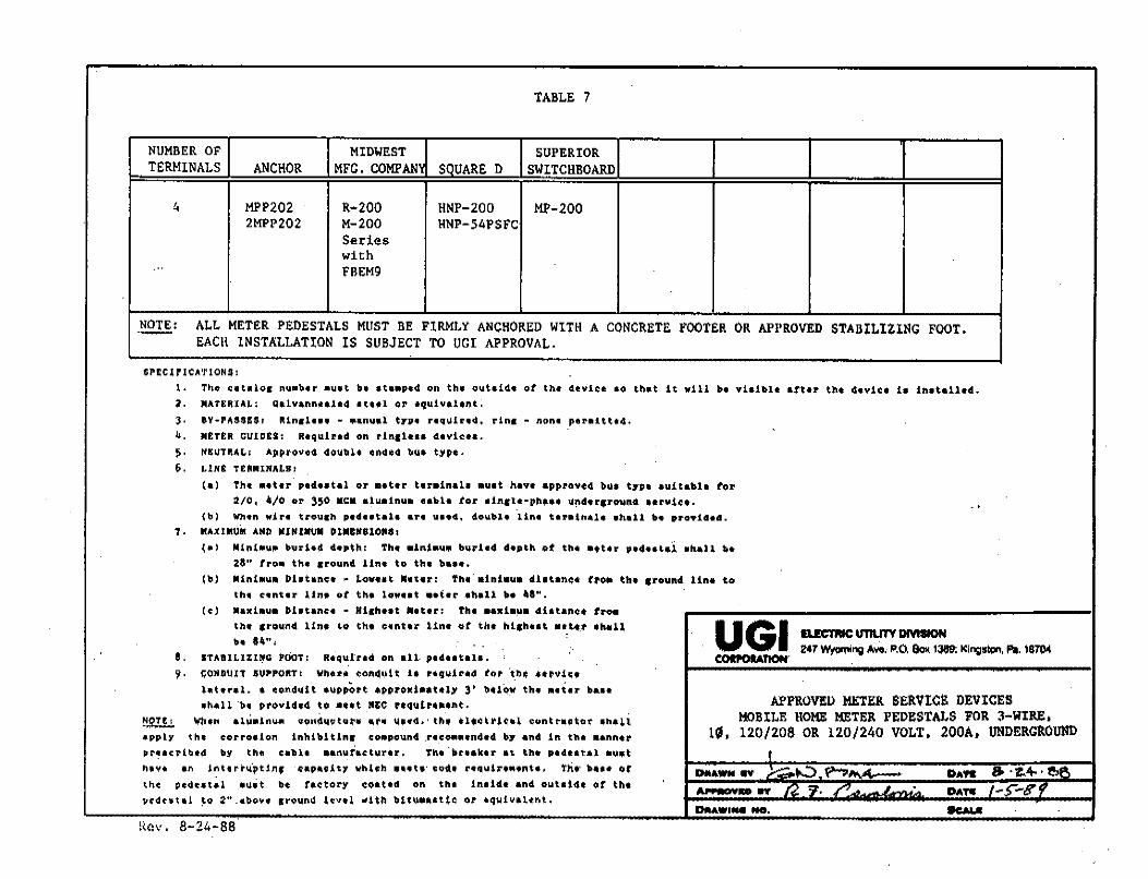
TABLE 7
NUMBER OF MIDWEST SUPERIOR TERMINALS ANCHOR MFG. COMPAN SQUARED SWITCHBOARD
4 MPP202 R-200 HNP-200 MP-200 2MPP202 M-200 HNP-54PSFC
Sedes with
·" FBEM9
NOTE: ALL METER PEDESTALS MUST BE FIRMLY ANCHORED WITH A CONCRETE FOOTER OR APPROVED STABILIZING FOOT, EACH INSTALLATION IS SUBJECT IO UGI APPROVAL.
SPEClPJC:A'rtONS:
I• Tll!Q' i:•ta101 nu"b•r 111u•t b• •t••P•d on th• ouhld• ot th.• deYl~111 &I) Uuit it will b• vi•il•l• att•.f U'1t 4•v1<:• l• lnatalled. 2, MATERIAL: Galvann••l•4 •t••l or equlvaltnt, J . 8V·PAUU1 ftln1l••• • ••nual trP• r•qUlr•d, rln1 - non• peraitt•4,
•• M£T£R GUlDU: Required on rin11••• devi~••·
~- N'E:UTJU.t.1 Approvo4 doublt ondt4 bu• typo, 6. i.1N£ TUNINALB I
(•) Th• ••ter p1d•atal or ••t•r terain•l• auat have approved bu• trP• auitabl• ff)r 2/0, •lo or 350 MCM aluainu• cabh tor ain11e-p~••• 1i!'\4•r•roun4 Hl'Y.let. . .
(\,) When win trcn11:h pede•tah u·• uae4, dcn1bJ.e ·uni t•r•tn.1111• •h•ll b• proYid•d. 7, MAXIMUM A"D •1"z•u• Dl.lN8lON81
(•) N1n1•u111 bvri•d d•pth1 Th• •lni•u.• bvr1•4 4•pth ot tb• ••t•r P•4••t•1 •hall•• 28" tro .. th• srou.nd Un• to th• b••••
(b) M1n1•u• Dl•t•nc• ~ Lov••t ••t•r: Th• •inl•u.• di•t.•n~• fto• th• ,round lin• to
tht c•nt•r line ot the low••t ••t•r •hall b• ••H· (.) Naxi•u• Dl•tanc• ~ Hi1h••t ••t•r: Th• •••1•~• diatanQt tro•
th• 1rou.nd Une to the c«ntu Un• at th ht,hHt H_t·•.r it;hdl UGI IL.!eTIIIC U'l1UlY DMIION b• '"'". 247 w,,,,,,;"11 Avo, P.O. 8"" 1J89: Ki"!l'm, Pa. 18704
8. STABlLlZl~G POOT: R•qulud. on all. pl4utai.. --· 9. CONDUIT .SUPPOll:TI WhftH (!Otklli,t!t h HiJU.lHd hf' 'th• Ul'Viu
htud. • ondut't •up,O,t •HHd•atitl)' 3' bU(p~ th• .. tu bau APPROVED MEIER SERVICt DEVICES •h,-11 ·t:t, provl4,4 to •o.t .,11:e ttquh••ut.
~ \li,'h•n alU•tnu• condu.etor• at• Ultd.·tht •l•~ttlt•l contractor •h•li MOBILE HOME MEIER PEDESTALS FOR 3-WIRE, •PP.l)' th, c-orro•ion inhibl tln1 eo•povn4 .nco11111111nd•d b,- •nd in tb• ••nn•t l~. 120/208 OR 120/240 VOLT, 200A, UNDERGROUND pr~acribtd ., the cabli ••n\liact.1,1.r•r. Th•.br••k•r at th1 Pldtat•l •u•t ' hi YI •n interi:'u.'pttn, capacity whhh 11ut•· coll.• n4\linM1nh, the• \Ht Of DtlA- IIY .!-:::'.....::>. ~ ... 4,.-- DAft & .z4-,,o...,
'"' p,4c•t11l ..... t •• r..ctory co•t•d on ... in1id• end o\lt•i4, or th• "-D IIY r.J "'f, f/ A _ I . DATIi f-5"~8"y pcdc•t1l ~o 2".abov• gro\lnd tcvel With b1t1,t•e•tt~ or •quiv11~nt,
DRAWi ... Nct, -ll(l\'. 8-21,-88
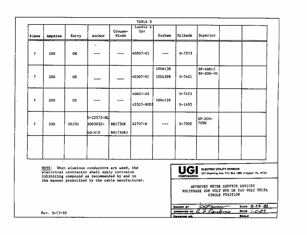
TABLE 8 Lnndis &
Crouse- Gyr UJaws Amperes Entry Anchor Hinda Durham Milbank Superior
.
7 100 OH --- --- 40507-01 --- U-7573
1004138 . BP-400-7 BP-200-7U
1 200 OH 40307-01 1004398 U-7421 - --
40607-05 u-7423
7 200 UG --- --- 1004139 42507-900 s-1493 ·
~-22572-Ml IlP-200-7 200 OH/UG S003032- RH173GR 42707-8 --- S-7000 7USW
UG-HlO RH173GRJ
'
NOTE: I/hen aluminum conductors are used, the u GI ,~CTl'IIC UTILITY DIVISION ~tr1cal contractor shall apply corrosion 2-47 Wyo'nlng Aw,.. P.O. SOI< 1389: K1ngs1on. Pi. 11.\704 inhibiting compound as reco,mnended by and in COlll'OMTION the manner prescribed by the cable manufacturer.
APPROVED METER SERVICE DEVICES . POLYPHASE 208 VOLT WYE OR 240 VOLT DELTA
SINGLE POSITION
' DIIAWN •• ,.- .. "\P':),., .. .......,...-' PATIC 6,z:4.AA ,.. • IIOlll'D ,r; rr, ;;: ,., .. 6 One /-C--K9' Rev. 3-17-92
""""
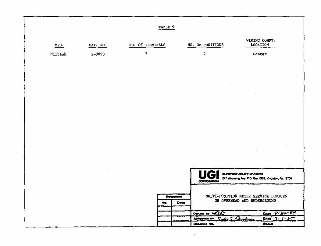
TABLE 9
WIRING COMPT. MFG. CAT. NO. NO. OF TERMINALS NO. OF POSITIONS LOCATION
Milbank S-9098 7 2 Center
UGI BKTIIICunun--247 Wr,,nil'Q ""*· P.O. llooc 13119: Ki'4111"", Pa. 1870< , . ..,.,......au ,
111:RI I • MlltTI•POSITION METER SERVICE DEVICES - DAft 311 OVERIIEAO AND UNDERGROUND
llu.wwff ...u, - DAn: ?-,.:2,- '¥']'-....... .,. - , - • ,r·~ • DAft .:1~ { -kC---- --
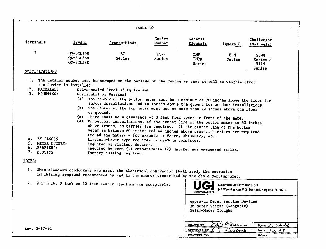
TABLE 10
Cutler General Challenger Terminals Br;i:ant Crouse-Hinds Halll!l!er Electric Square D (Sylvania)
7 QS-3CL1BR RY cc-7 TMP EZM SC~ QS~3CL211R Series Series TMPR Series Series & QS-3CL3BR Series M37M
SPECIJ.'ICATIONS: Series
1. The cata1og number must be stamped on the outside of the device so that it will be visible after the device is installed.
2. 3.
MATERIAL: Galvannealed Steel of Equivalent MOUNTING: Horizontal or Vertical
BY-PASSES: 4. 5. METER GUIDES: 6, BARRIERS: 7. BUSSING:
NOTES:
(a} The center of the bottom meter must be a minimum of 30 inches above the floor for indoor installations and 44 inches above the ground for outdoor installations.
(b) The center of the top metet must not be more than 72 inches above the floor
(c) (d)
or ground. There shall be a clearance of 3 feet free space in front of the meter. On outdoor installations, if the center line of the bottom meter is 60 inches above ground, no barries are required. If the center line of the bottom meter is between 60 inches and 44 inches above ground, barriers are required around the meters - for example, a fence, shrubbery, etc. Ringless-Lever type requires, Ring-None permitted. Required on ringless devices, Required between (1) compartments (2) metered and unmetered cables, Factory bussing required.
1, When aluminum conductors are used, the electrical contractor shall apply the corrosion inhibiting compound n,commended by and in the manner prescribed by the cable manufacturer. i-------------------1
2, 8.5 inch, 9 inch or 10 inch center spacings are acceptable.
Rev, 3-17-92
UGI £1.l!CffllC U11UTV D1V1$10N
247 Wyoming A~. F'.O, 8oJ: 1389, K1ngstoo. Pa 18704 (Oll'OIIATION
Approved Meter Service Davices 30 Meter Stacks (Gsngsble) Mv.lti-Meter Troughs
D1111AWti4, •V '.:,(. ."'I y--oi!Jl-\&>.M.-. """"°""o.., fZ t" £:, j ___ ~
0111AWtN• HO,
DATO D •"2.4 ·~ DAn /-f•.1/"li' . ., .......
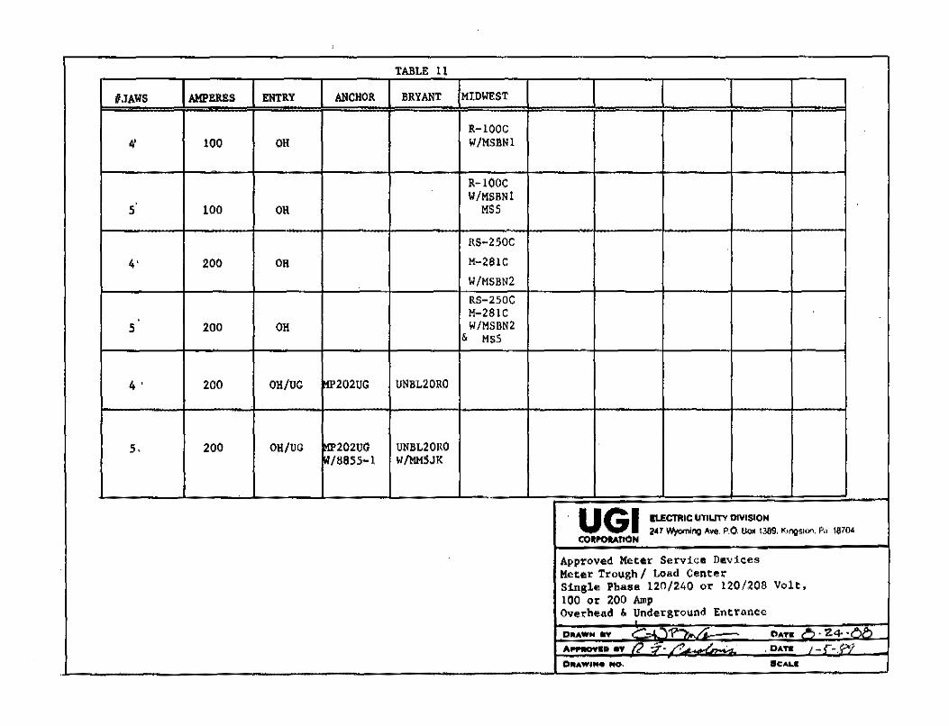
TABLE 11
I/JAWS AMPERES ENTRY ANCHOR BRYANT MIDWEST
R-lOOC 4' 100 OH W/MSBNl
R-lOOC W/MSBNl .
5 100 OH MSS
RS-250C
4' 200 OH M-281C
W/MSBN2 RS-250C M-281C
5 200 OH W/MSBN2 & MS5
4' 200 OH/UC ITT'202UG UNBL20RO
s. 200 OH/UG 11!'202UG UNBL20RO ~/8855~1 W/MMSJK
u GI EI.ECTRIC UTILITY DIVISION 2•1 IV)<oming Avo. P.O. 8"" 1389, ~,ngs,QO. P• 1870<
co,POMtlON
Approved Meter Service Devices Meter Trough/ Load Center Single Phase 120/240 or 120/208 Volt, 100 or 200 Amp Overhead & Underground Entrance
DllAW.. flY _, yy·- ,,,. CIATO ,-., • Z4 · ,..,...,
All'PMW•D 1W ,.., -:r-/.'. , .DAH , -i-P~
0ll!IAW'f"4 NO, lfCALI

T
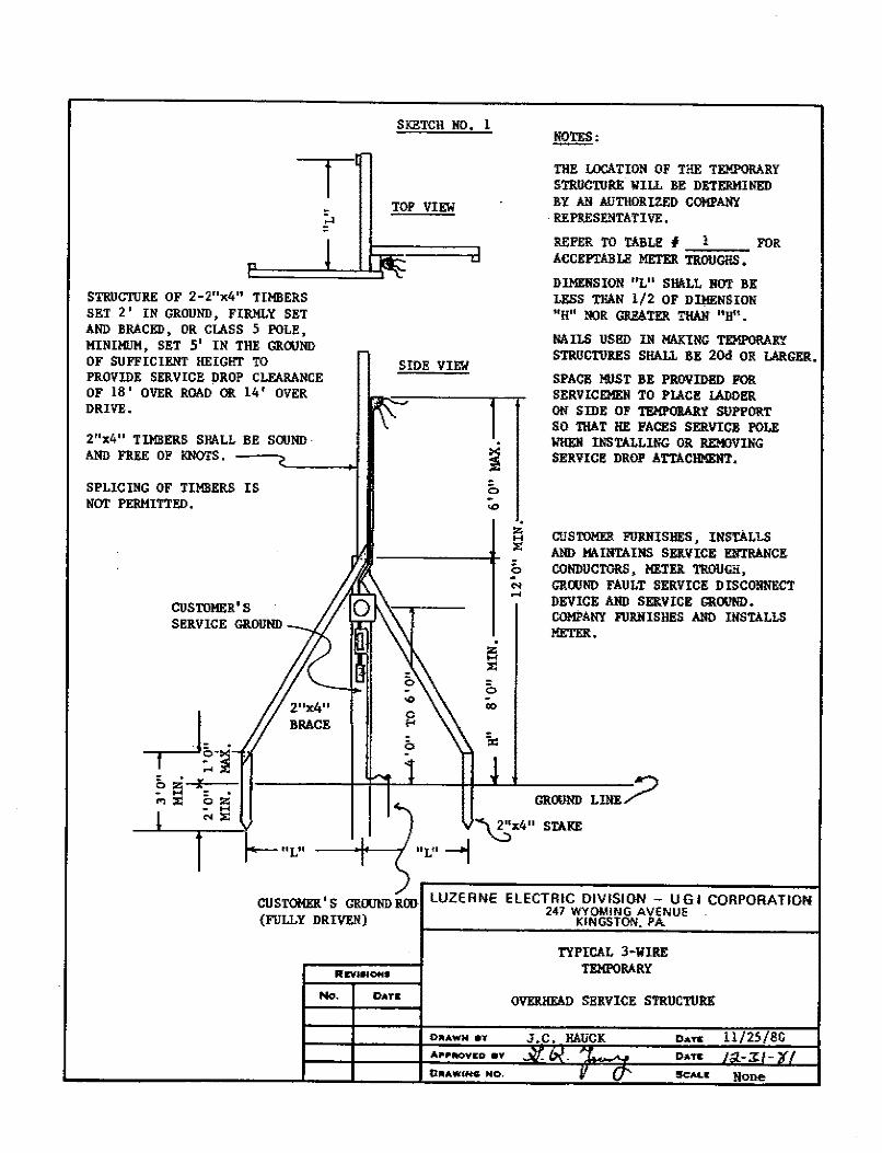
STRUCTURE OF 2-2"x4" TIMBERS SET 2' IN GROUND, FIRMLY SET AND BRACED, OR CLASS 5 POLE, MIN Ill!JM, SET 5' IN THE GROOND OF SUFFICIENT HE IGl!T TO PROVIDE SERVICE DROP C LF.ARANCE OF 18' OVER ROAO OR 14' OVER DRIVE.
2 "x4" TIMBERS SHA LL BE SOUND · AND FREE OF KNOTS.
SPLICING OF TIMBERS IS NOi' PERMITTED.
SKETCH NO. 1
TOP VIEW
SIDE VIEW
. ~ :,:
0 00
0 N ...
!Qlli:
THE LOCATION OF THE TEMPORARY STRUCIDRE WILL RE DETERMINED BY AN AUTHORIZED COMPANY REPRESENTATIVE.
REFER TO TABLE# l FOR ACCEPIABLll METER TROUGHS.
DIMENSION "L" SHALL NOT RE LESS THAN 1/2 OF DDIENSION '
1H11 00:R GR.E6.TER THAN "Hn.
NAllS USl!D IN MAKING TEMPORARY STRIJCn!RES Sl!AL1 BE 20d OR LARGER.
SPACE MUST l!E PROVIDl!D FOR SERVICEMEII TO PIACE IADDl!R ON SIDE OF Tl!MPORARY SUPPORT SO THAT HE FACES SERVICE POLE WHEN INSTALLING OR REMOVING SERVICE DROP ATTACHMEHT.
CUSTOMER FU!UUSHES, INSTALLS AND MUNTAINS SERVICE E!l'IRANCE CONDUCTORS, HETER TROUGH, GROOND FAULT SERVICE DISCONNECT DEVICE AllD SERVICE GROUND. COMPANY FUIUIISHl!S AND INSTALLS METER •
CUSTOMER'S GROUNDROO LUZERNE ELECTRIC DIVISION - UGI CORPORATION 247 WYOMING AVENUE
{FULLY DRIVEN) KINGSTON, PA
TYPICAL 3-WIRE
REVlSIOH9 TEMPORARY
No. DATI OVERllEAD SERVICE STRUCnJRE
:DIIIAWN ay DAff
APPIIOYED aY- D"tt
O!IIIA.Wlfot& NO. SeM.E None
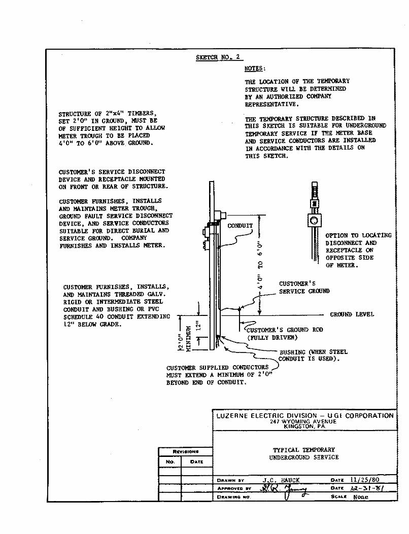
STRUCnJRE OF 2"x4" TIMBERS, SET 2'0" IN GROOND, MUST BE OF SUFFICIENT HEIGHT TO ALLOW METER TROOGH TO BE PU.CED 4 ' 0" TO 6' 0" AllOVE GROUND •
CUSTOMER'S SERVICE DISCONNECT DEVICE AND RECEPTACLE MOONTl!D ON FRONT OR REAR OF STRUCnJRE.
CUSTOMER FURNISHES, INSTALLS AND MAINTAINS HETER TROUGH, GROOND FAULT SJ!llVICE DISCONNECT DEVICE, AND SERVICE CONDUCTORS SUITAIILE FOR DIRECT BURIAL AIID SERVICE GROOND. COMPANY FURNISHES AND INSTALLS METER.
CUSTOMER FURNISHES, INSTALLS, AND MAINTAINS THREADED GALV. RIGID OR INTERMEDIATE STEEL COIIDU IT AND BU SH ING OR PVC SCHEDULE 40 CONDUIT EXTENDING 12" BELOW GRADE.
SKETCH NO. 2
NOTES,
THE LOCI. TION OF THE TE!!i'ORA!lY STRUCTIJRF. WIU BE DETERMINED EY AN AUTHORIZED COHPAN!'. Ri!PRESDITATIVE.
THE TEMl'ORARY STRUCTURE DESCRIBED IN THIS SKETCH IS SUITAllLll FOR UNDERGROUND TEl!PORARY SERVICE IF T!!E METER JASE AND SERVICE COtiDUCTORS ARE INSTALLED IN ACCORDANCE WITH THE DETAILS ON TRIS SKETCH,
L-J
q : CONDUIT r ( L-5 0
OPTION TO LOCATING DISCONNECT AND RECEPTACLE ON OPPOSITE SIDE
~ OH ;r- z I "' ... ..a..:,:--
"' 0 ... OF METER •
CUSTOMER'S .,,->..,_---SERVICE GROOND
IL.---V'
~TOMER' S GROUND ROD ~(FULLY DRIVEN}
GROOND LEVEL
" .'k... ___ ~ BUSKING (WIIEN STE.EL
CUSTOMER SUPPLIED CONDUCTORS ~CONDUIT IS USED).
MUST EXTEND A MINIMUM OF 2 '0" BEYOND END OF CONDUIT.
No. DATE
LUZERNE ELECTRIC DIVISION - UGI CORPORATION 241 WYOMING AVENUE
KINGSTON, PA.
TYPICAL TEMPORARY UNDERGROUND SERVICE
DRAWN ..... J.C.. HAUCK D•TE 11/ 25/80 D•n ~ :!>1-lff
01lAWINQ. HO. ll U Sc."u: None
SKETCH NO. 3
ROOF EDGE
' II
I ' I I
I ' i I I I / I I I I /
·--··-·· - --·---
12" MIN, -:-l... COMPANY PROVIDES ........,, . ANCHOR TO BE '.:::::;.; INSTALLED BY @ CUSTOMER----, / . ·-··----- --1 L-/
.. ··-··--· --·
LINJ!(IDE
LOAD SIDE ©
w....- 3 1 MINil'IJM---+1 CLEARANCE TO ANY BUILDING OPENING.
- ------___ _,
CUSTOMER'S
GROUND WIKE ----
CUSTOMER'S GIIOU1ID ROD
(FuLLY DRIVEN)
No.
~CUSTOMER HIST
0
"' i:: 0 <t
PROVIDE 3 1 MINUIJM TAIL
l'O" MINIMUM TO END OF BUIIDING
o< i 0
"' N
ROTE:
ALL METER LOCATIONS MUST BE DESIGIIA'l'Ell BY AN AlmlORlZED COMPANY REPRl!Sl!liTATlVE.
REFER TO TABLE II FOR ACCEPTABLE HETER TROUGHS.
COMPANY SUPPLIES l!l!TER, SD.VICI! DROP ANCHOR ARD SEP.VICE DB.OP.
LIRE AND LOAD SIDES OP METER SOCKET MAY BE ARY COMBINATION OF APPROVED SERVICE CABLE OR Al'PROVBD CONDUIT.
LOAD SIDE SERVICE CABLE (AS SHOWN) OR CONDUIT CAN BE ELIMDIATED WBElf EIITRAllCE TO SERVICE PAllEL IS MADE TllllOIJGH BAC1C OP METER SOCKET.
GR001iD LEVEL
LUZERNE ELECTRIC DIVISION - UGI CORPORATION 247 WYOMING AVENUE
DATIi
KINGSTON, PA.
TYPICAL OVERl!EMl SERVICE 100 AMP & 200 AMP
9-21-82 DIIU,WN •y
011AWl~Q HO. Sc.ALE Non-e
-
SKE'ICH NO. 4
ROOF EDGE
_/ -·- !,_' ------ /
-----
I+-- 3'MIHDIJM-TO ANY i;~i;I: ;!; BUIIDIHG :' i5 OPENING : i
CUSTOMER'S GROUIID WIRE
.. = 0 00
~:... "'
I'O" MINIMUM TO END OF BUILDING
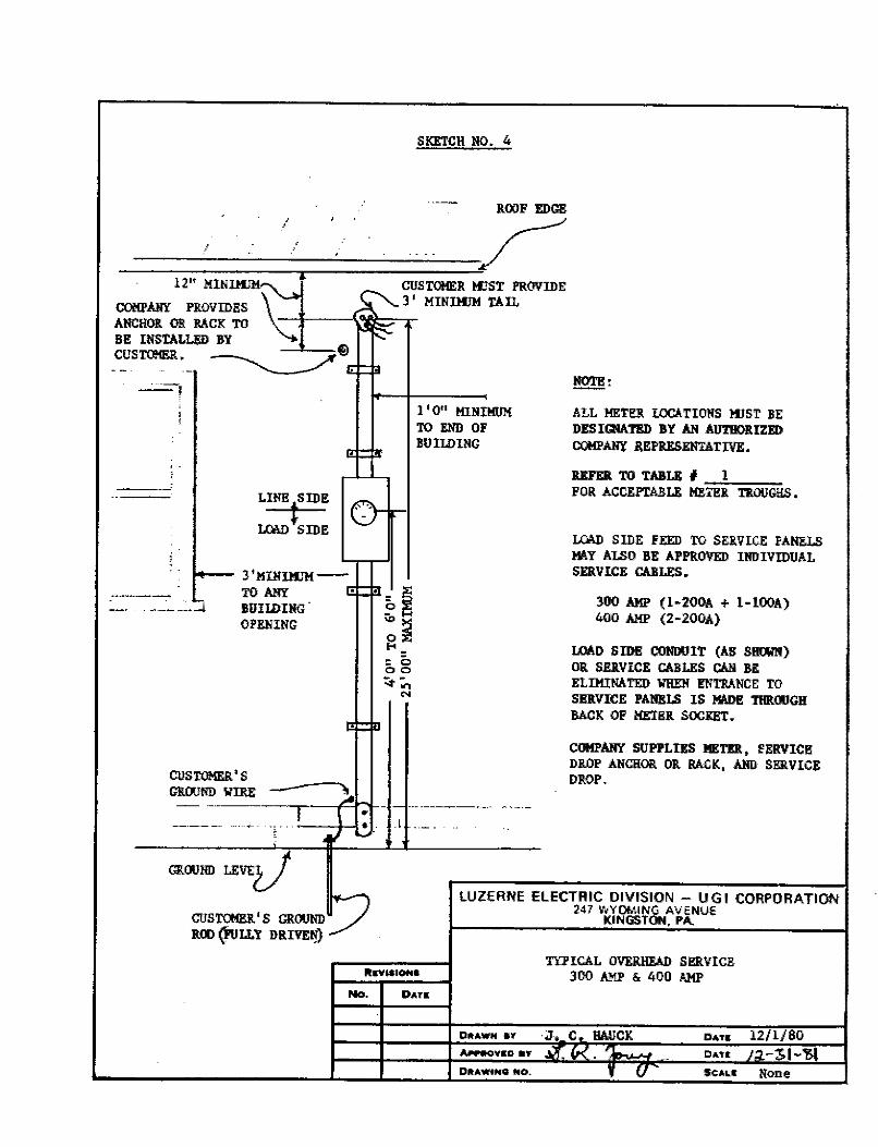
!!Q!§:
ALL METl!lt LOCATIONS HJST BE DESIGNAT!!D BY AN AUTIIORIZED COMPANY REPRESENTATIVE.
REFER TO TABLE # I FOR ACCEPTARLE ME_TE_R.c._D ___ OO __ G!!S_ •
~ SIDE FEED TO SERVICE PANELS MAY ALSO BE APPROVED IBDIVIDUAL SERVICE CABLES.
300 AMP (l-200A + 1-lOOA) 400 AMP (2-200A)
LOAD SIDE COBOOIT (AS SHWN) OR SERVICE CABUS CAN BE ELIMINATED WIIEII ENTRANCE TO SERVICE PANELS IS MM>I! THROUGH BACK OF METl!ll SOCKET.
COMPANY SUPPLIES METER, fERVICE DROP ANCHOR OR BACK, AllD SERVICE
_ DROP. ~ - -----------~--r:-::rl--- - ------·--· -----\ .
__ ,._. •.. L ··--; I ~
GROUNll 13,VEV CUSTOMER'S GROUNDr) ROO {FULLY DRIVE!J)
1
_.,/
No. DATIi
LUZERNE ELECTRIC DIVISION - UGI CORPORATION 247 WYOMING AVENUE
KINGSTON. PA.
TYl'ICAL OVERHEAD SERVICE 300 AMP & 400 AMP
Dl!tAWN ·" ·J-. c .. HAUCK ~vso av ~-- f.l DIIU.W.NG 110. V
D4TS 12/1/80 D4TE /:J 3,l-'61 Sc::Au None
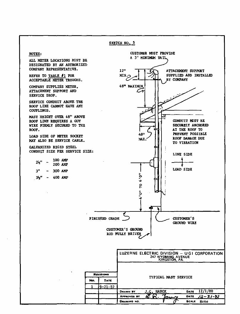
NOTES:
ALL METER LOCATIONS MUST BE DESIGNATED BY AN AUTIIOR.IZED COMPANY REPRESENTATIVE.
REFER TO TABLE #1 FOR ACCEPTABLE METER TJ.OIJG!!S.
COMPANY SUPPLIES METER, ATIACIIMENT SUPPORT AND SERVICE DROP.
SEllVICB CONDUIT ABOVE THE ROOF LINE CANNOT HAVE ANY COUPLIHGS.
MAST HEIGHT OVER 48" ABOVE ROOP LINE REQUIRES A GUY WIRE PIRMLY SECURl!D TO THE ROOF.
LOAD SIDE OF Ml!TEll SOCKET MAY ALSO BE . SKltVICE CABLE.
GALVANIZED RIGID STEEL
SICET<:H NO. S
CUSTOMER 111ST PROVIDE A 3' MINIMUM TAI
12"
MINUi.-1-- ...........
48" MAX
ATEACHMENT SUPPORT SUPPLIED AND l!ISTALLED BY COMPANY
CONDUIT !l!ST BE SECUlll!LY ANCHORED AT THE ROOF TO PREVENT POSS IBLE ROOF DAMA.GE DUE TO VIBRATION
CONDUIT SIZE PER SERVICE SIZE:
2½:" _ 100 AMP 200 AMP
3" 300 AMP
3½;" - 400 AMP
P IIUSl!!D GRADE
LINE SIDE
l LOAD SIDE
CUSTONER.'S GROOHD WIRE
CUSTOl!Ell'S GR.OOHI)
ROD PULLY DRIVEHV
No. DATE
1 -21-82
LUZERNE ELECTRIC DIVISION - U G I CORPORA TJON 247 WYOMING AVENUE
KINGSTON, PA
TYPICAL MAST SERVICE
DIIAWH aY OATII
APPIIOYID SY
0RAWING NO. SCALI: None
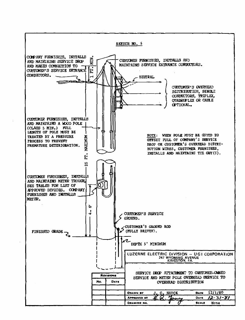
COl'ANY FURNISHES, INSTALLS z AND MAIN1'Ail6 SERVICE IECP !./ AND MAJ::ES CONNl:Cl'ION TO ~·s SERVICE mmm:: •
t:: OOND!.C'IDRS. ~-----,(,._
ClB'lUIER FOR.NISHES, INSTALLS AND MAIN1'AIN3 A iOJD POLE (CLASS 5 MIN.) FOLL LENGTil OF POLI! :IIIST RE
TREATED BY A PRESSDRF. I PROCESS TO PREVENT PREMATURE DE'rERIOl!ATION.
• t: .,, ..
....
CU3'IU(ER FllR!USHES, I!mJ AND MAil,ll'AOO METER TRO SEE TABLES FOR LIST OF APPROVED DEVICES. CXJ!PANY FllRNISHE3 AND I.NS'.l'ALLS _..µ,., KEI'ER.
• ~
SKETCH !IO. 6
CW'l'CtiER FURIHSHES, IlfflALLS AND MAINI'AINS SERVICE EN'fflA!CE COllll£'l"ORS.
r NEUrRAL
--- ClB'.OCMER'S OVERHEAD DIS'l'RIWJ:ION, SINGLE CO~, TRIPLEX, QUAJ:im'LEX OR CAILE CPTIONAL.
ROTE: WHl!II POLE HIJST BE GUYED TO OFFSET PULL OF Cl»IPANY' S SERVICE DROP OR CUSTCl'IER'S OVERJ!EAD DISTRI· BUTION WIRES, CUSTOMER FURNISHES, INSTALLS AND MAINTAINS THE GUY {S} •
CIBTClml'S SERVICE GROUND.
<( CUSTC»IEI!.' S GROUND ROD V (FULLY DRIVEN).
DJ;P'll! 5 ' MIJUMUM
LUZERNE ELECTRIC DIVISION - UGI CORPORATION 247 WYOMING AVENUE
KINGSTON. PA.
I I I J r I , ___ .,__._I
No. DATIi:
SERVICE Il1CP ATT.nmtmrr TO CW'l'CHER-CMNED SERVICE AND ME.TER POLE OVERHEAD SER'IICE TO
OVERHEAD DIS'l'RifmION
0JIAWH •'t
APPltOVED •Y- Du• 011tAW1NG NO~ Sc,a,u None.
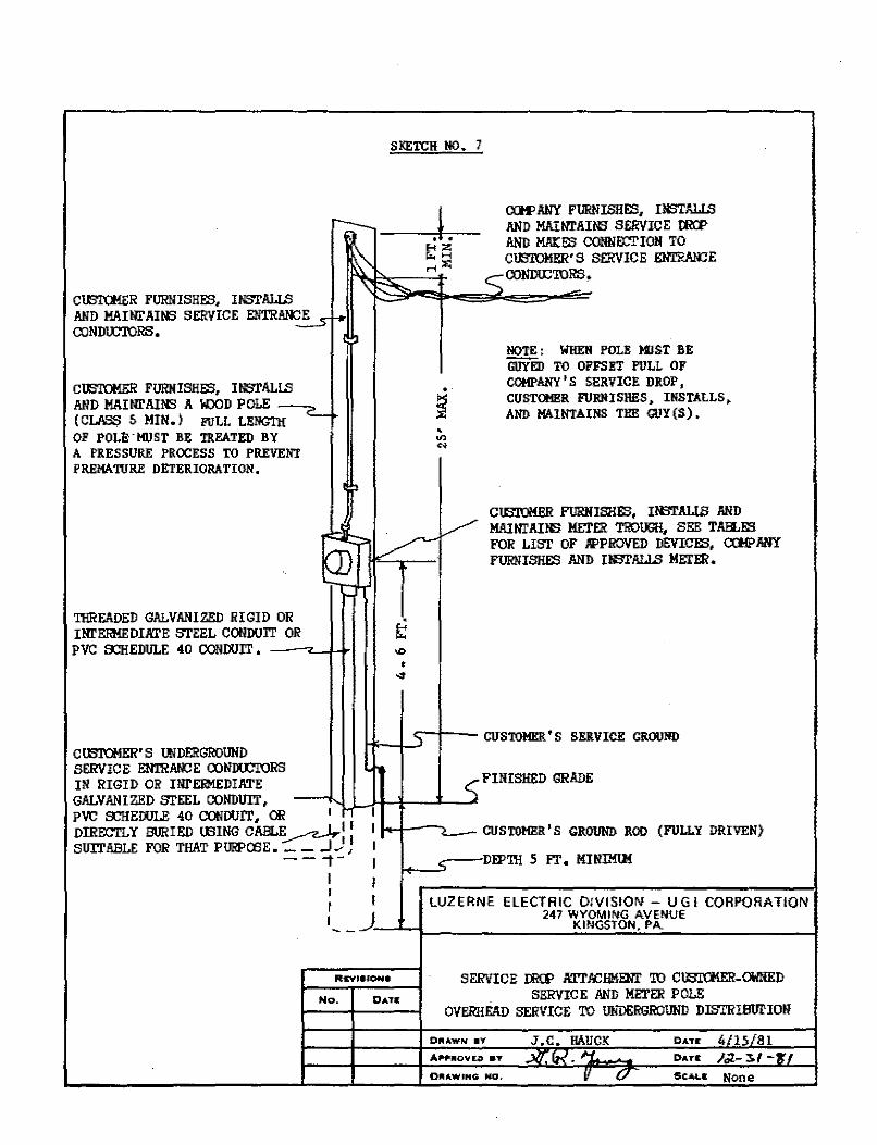
SKETCH NO. 7
r---_~ --.L-E-I z «.H
~ H :0:
CCH'ANY FURNISHES, IKSTAl.lS AND MAINI'AINS SERVICE tRCI' AND MAKES CONIIOCTIOH TO CU3'IOMER'S SERVICE ENTRANCE
CIBI'CMER FURNISHES, INSTALIB AND MAINl' Allfl SERVICE ENTRA!C ~ 1-o CONDOC'IQRS. 1 l
CUSTCMER FURNISHES, I NSTAL!.'3 AND MAI NI' Allfl A w::xJD POLE ( CLAS.S 5 MIN.) FULL LENGTH~ • OF POLI, · HUST BE TREATED BY A PRES SURE PROCESS TO PREVENT PREMATURE DETERIORATION.
I >
. .., <v
C::::::CONDU:'ro~.
NOTE: WHEN POLE WST BE GUYED TO OFFSET PULL OF COMPANY'S SERVICE DROP, CUSTO!l!R FURNISHES, INSTALLS, AND MAINTAINS THE GIIY(S) •
ClBIUMER FURIUSl!ES, IN3'I'ALIB AND l..l . I,,/" MAIIII'AINS HE:l'ER TROUGH, SEE TAB.ES
Q)- - V'- FOR LIST OF JIPPROVED DEVICES, CClfPANY . T ...,,,,, .... .,., ,,.,,.,..., ,,.., .
'Il!READED GALVANIZED RIGID OR INr EEiME DIA'.I'E STEEL CONDUIT OR PVC s:::HEDULE 40 CCNDUIT, _ ___,.___µ.
CWT(!,!ER'S WDERGROUND SERVICE EN'rn!\H:::E CONIXCI'ORS IN RIGID OR INI' ERMEDIATE
t
' CUSTOMER'S SERVICE GROUND
GALVAN I ZED STEEL CONDUIT, PVC s:::HElJULE 40 CONDUIT, OR 1 ~
,;- FINISHED GRADE
.L~l-t-¼---'--J.
DIRECTLY BURIED !BING CABLE - LI 1 :.,..--'-7...J I I SUIT ABLE FOR THAT P URPOO E • - - .., , ---t-
i
I k-1------i CUSTOMl!R 'S GROUND ROD (FULLY DRIVEN)
c--DfPIB 5 fT. MINIMIM I I ! -
I r I LUZERNE ELECTRIC 0/VISIOIII - UGI CORPORATION I _j 247 WYOMING AVENUE __ ---'-1--------~K~IN~~~TO~N~,~P~A;..... ______ -1
No.
SERVICE IRCP ATr/CHMEm' TO ClBIOIER-OWNED SERVICE AND METER POLE
OVERHEAD SERVICE TO UNDERGROUND DISTRIBllrION
DIii.AWN" •Y J.C, HAUCK Dur 4/U/81 Dur /,;t.- :S.( _.,,
OU.WlNG NO. V 0 SCALE None
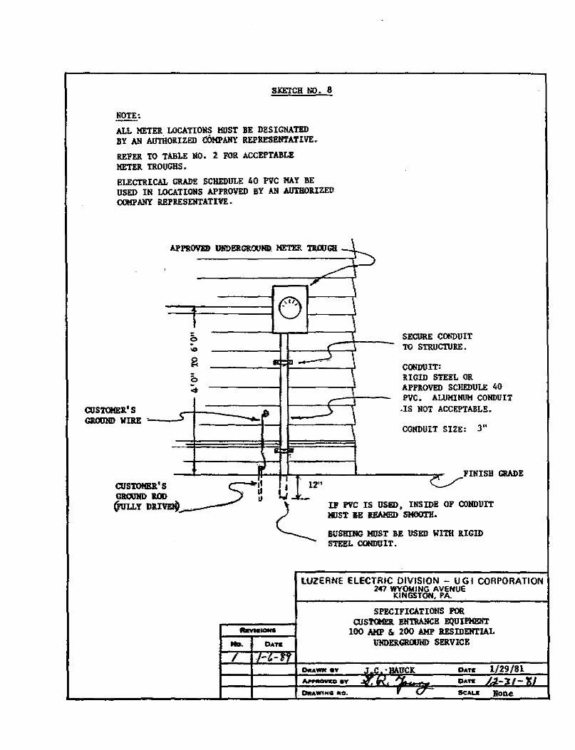
SXETCH NO. 8
NOTE:
ALL METER LOCATIONS HOST BE DBSIGIIATED BY AN AIJTHOllIZED COMPANY REPRBSl!NTATIVE.
REFER TO TABLE NO. 2 FOR ACCEPTABLE METER TROUGHS.
ELECTRICAL GRADE SCHEDULE 40 PVC MAY BE USED IN LOCATIONS APPROVED BY Ml AllTIIOllIZED COMP ANY REPII.ESENTATIVE.
APPII.OVED llli!)l!RG&OOIID HETEll TRWGI! -~
' --0 ...
I 0 SECURE CONDUIT
"' , TO STRIICTORE.
~ ID-\ .~ - -
CONDUIT: b llIGID STEEL OR
<t APPROVED SCl!EDIJL! 40 , PVC. ALUMINIJH COIIDI! IT
CUSTQ!Ell' S II '> -IS NOT ACCEPTABLE. GllOOHD WllE - '
CONDUIT SIZE: 3"
- : .. ••• FINISH GRADE I
CUS1'0Hl!ll.'S ~11 I 112" .. GIIWllDIOO ' II l., II !juu. Y DllIVEIO . . 2-__
IP PVC IS USl!I), INSIDE OF CONDUIT l!IJST BE l!EAMl!I) SMOOT!!.
BUSIIIIIG MIJST BE USED WITH ltlGID STEEL OONDUIT.
LUZERNE ELECTRIC DIVISION - U G l CORPORATION 247 WYOMING AVENUE
KINGSTON, PA.
SPBCIFICATIOIIS FOR aJS?Q!EI. l!li1.'IWlCE EQUIPMBNT -- 100 AMP &, 200 AMP IIESIDEHTIAL
No. DAff 11NDERCRWriD SERVICE
/ .,_,_,.,
Dtti\WK •Y .t " .u•ucK DAtt 1/29/81 Jl+,iiilOUCD ff J/T. IK, rr. DAff J~-lf-'U
_ OttAwtNG .io. , V S<:AUI Rone
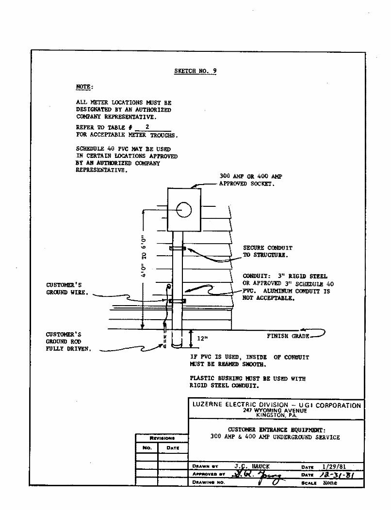
SKETCR HO. 9
!!,l!!!:
ALL METER LOCATIONS KJST BE DESIGNATED BY AN AUTHORIZED COMPANY REPRESENTATIVE.
REFEll TO TABLE # 2 FOR ACCEPTABLE METER TROUGHS •
SCllEDOLE 40 l'VC MA.Y BE USED Ill CERTAIN LOCA.TIOHS APPROVED BY AN AUTll)RIZED COMPANY REPR.ESEIITATIVl!.
3-00 AMP OB. 400 AMP Al'l'i.OYED SOCKET.
- ~ '
-
0 -'° SECURE COODUIT
~ .._
TO STRIJCTUU. -0 -st CO!iDUIT: 3" RIGID STEEL
CUSTOHER.'S - OB. APPROVED 3" SCBEDUU! 40 1.--- / ._-.PVC. ALllMilllJM COl!DUIT IS GR.QIIID WlllE. - ., HOT ACCEPTABLE •
1 FINISH ~E=:> CUSTOMER'S '
~ _J 12" GR.ODND ROO II
FULLY DRIVEN, ~q
IF l'VC IS USED, Il!SIDE OF CONDUIT IIJST BE UAMED SMOOTH.
PLASTIC BUSHING 111ST BE USl!D WITH lllGID STEEL cormurr.
LUZERNE ELECTRIC DIVISION - UGI CORPORATION 247 WYOMING AVENUE
KINGSTON, PA.
CUSTOM!llt Elil'RANCE BQUil'MEIIT: IIIIYl•ION• JOO AMI' & 400 AMI' UliDERGRWIID SERVICE
No. DATI
DIIAWN .... J.C. HAUCK DAff 1/29/81 ~-0 •• ~ ,..,
Due ,N}.-'tl-~I • DIIAWI,- NO.
, V SCM.S None
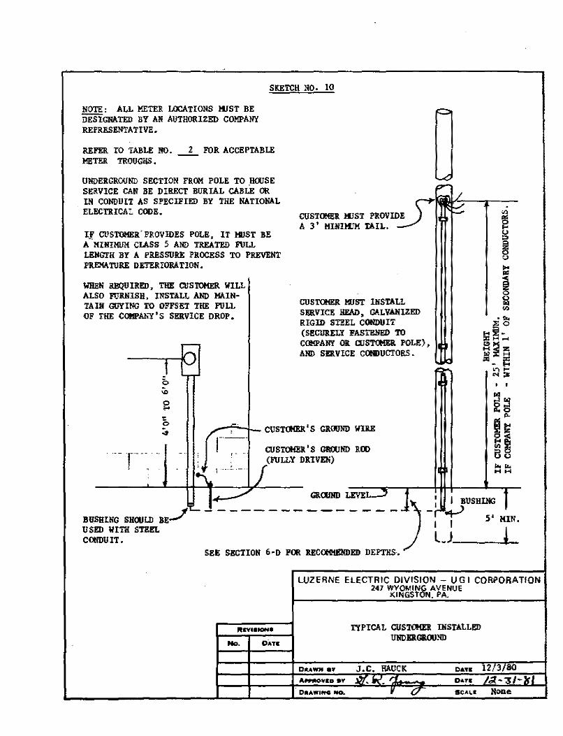
SKETCH NO. 10
NOTE: ALL METEI! LOCATIONS KIST BE DESIGNATED l!Y AN AUTHORIZED COMPANY REPRESENTATIVE.
REFER TO TABLE NO. _2_ FOR ACCEPTABLE H!TER TROUGHS.
UlIDEl!Gl!OUIID SECTION FROM POLE TO _BOOSE SERVICE CAN BE DIRECT BURIAL CABLE OR IN COffllUIT AS SPECIFIED BY THE NATIONAL ELECTRICAL CODE.
If CUSTOMER" PROVIDES POLE, IT KIST BE A MHH!IIJM CLASS 5 AND TREATED ruu Li!.lfGTH BY A PRESSURE PROCESS TO PREVENT PREMATURE DETERIORATION.
liHBN REQUIRED, THE CUSTOMER WILL ALSO FUIUUSH, INSTALL AIID MAINTAIN GUYING TO OFFSET THE PULL OF THE COMPANY'S SERVICE DROP.
CUSTQIER 111ST INSTALL SERVICE HEAD, GALVANIZED RIGID ST1!EL CONDUIT (Sl!CllltELY FASTBlil!D TO COMPANY Olt CUS'l'Ct!ER POLE), AND SERVICE COOIJUCTORS.
-.,.,;.....J_CUST(JIEll.'S Gl!OOliD WillE
r---_ - CUST<lll!l!'S GROOND 1!00 (nJLLY DRIVEN)
. '
Gl!Clll!D LEVEL I I BUSHING ---------------:, l_J __ 5_•_1_N. BUSHING SHOULD BE_/ USED IIITII STEEL COffllllIT.
SEE SECTION 6-D FOR llECOMH£NDED DEPTHS.
lln11fONI
No. DAn
LUZERNE E LE CTR IC DIVISION - U G I CORPORATION 247 WYOMING AVENUE
DUWN e¥
D•AWI .... MO.
KINGSTON. PA.
TYPICAL CUSTCIID. INSTALLED UllDEl!GllOUND
DATE
OATS
SCALE None
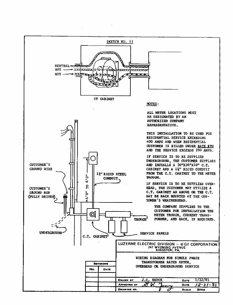
SKETCH NO. I l
NEUTRALHOT -=*===/· HOT-
CT CAIHNET NOTES:
ALL HETER LOCATIONS !IUST BE DESIGNATED BY AN AUTIE)RlZEI> COMPANY REPRESl!NTATIVE.
THIS IHSTALLAITON TO J!.I! USED FOR RESIDENTIAL SERVICE EXCEEDING 400 AMPS AND IIHEN RESIDENTIAL WSTctlER IS BILLED UNDER RATE RTII AND THE SERVICE EXCEEDS 200 AMPS.
CUSTOMER'S GROUND WIRE
~ ...... s (
lo 1.1;" RIGID STEEL
COODUIT_}
r
IF SERVICE IS TO Bl! SUPPLIED UNDERGROUND, THE CUSTOMER SU!'PLlES AND INSTALLS A 36"X36"X10" C. T. CABINET AND A 1½;" RIGID CONDUIT FROM THE C.T. CA.J!.INET TO THE METER TII.OUG!!.
GROUHD ROD \
(FuLLY DRIVE!f)2-..
,'.;L~::==1 ,_, /, .,, .,
UNDERG:~ND)
Rcv.t•IONII
No. DATIi
IF SERVICE IS TO l!E SIJPPLIED OVERHEAD, THE CUSTOMER MAY UTILIZE A C,T, CABDIET AS ABOVE OR THE C.T. MAY llE RACK KXJNTED AT THE CUSTOMl!R' s Wl!ATIIEIU!EAD.
THE CCl!PANr SUPPLIES TO THE CUSTOHEII. FOR INSTALLATIOII THE METER TROUGH, CURRENT TRANSFORMER, AND RACK, IF REQUIRED.
SERVICE PANELS
LUZERNE ELECTRIC DIVISION - UGI CORPORATION 247 WYOMING AVENUE
KINGSTON. PA.
WIii.ING D lAGRAM FOIi. SINGLE PHASE TRANSFOl!MEJ. RATED METER,
OVERHEA!) OR UNDERGROUND SERVICE
DATC 1 22 81 DATE /.;l.-;l /- 'J;j
OllAWINQ NO. Scau: Hone
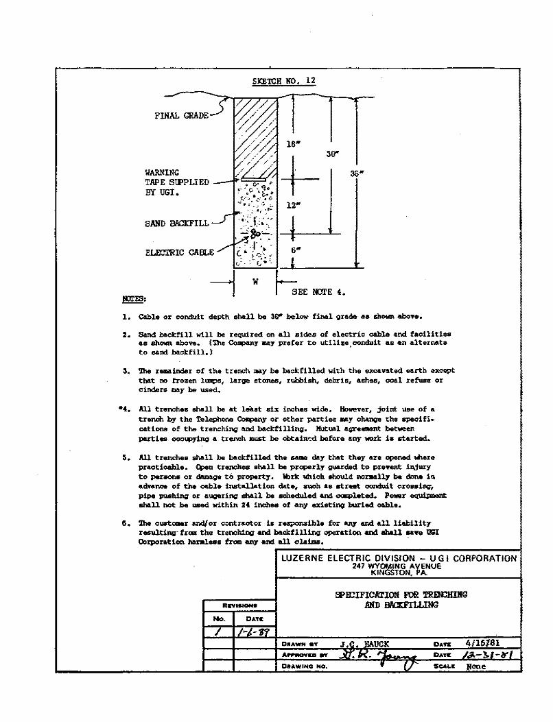
FINAL GRADE
I/ARNING TAPE SlPPUED BY UGI.
SAND BACD'ILL
EIB:.l'RIC CABLE
~=
/
SKE'l'CH NO. 12
30"
12"
w ~EE NCII'E 4.
1, Cable or oondult depth shall be 30" below fi,..l grade as shown above.
2. Sand bacl::fill will be required on all .sides of electrio cable e.nd. facllit iaa •s ah.own above... (Th.e CompanJ' may prefer to utilize, conduit as &n alternate to sand bool:fl 11. )
3. '!he remainder of the trench may be bool:fllled with the excanted eorth exoept that no frozen lmip,s, large stones, rubbish, debris,- ash-es, coal .refuse or -cinders- ma.y be used.
•t. All trenches shall be at lefl.at •ix inches wide. Elowever, joint use of s.
trench by the Tel.ephone ~Y or other po.rtiea uy ch,mge the spec! fi. oat ions of the t renchinge and bacl:fi lling. Mutual ai;ireement between puties -oooq:,ying a trench must be obtain-::d before any wo.ri: ia started.
s. m trenches shall be bacl:filled tha - day that they are -Md .... r. procticablo. 4'en trenches a hall be praperly guarded to preftltt iajury to per80llS or doll>oge ti> property. ibri:: ,,hloh ohould nomdly be done ill ,advance of the oable instsl.lat:lon date, auch •• at.rut conduit oroa•lns1, pipe pushing or a,~arinl)' shall be scheduled and -1atad. Powr equipoant sho.11 not be ""8d within H inches of any existirq hurled oahlo.
6. 1ha c""1:,_r end{ or contrsot<>r 1B responsible for any and all liebility ruu.lting· fraa the trenching and bocl::flllirlQ' oponti<>n and ahal.l ... .,. UGI O:,rporation hanll.ess from any and all cl&lms. ·
No. DATI:
I
LUZERNE ELECTRIC DIVISION - UGI CORPORATION 247 WYOMING AVENUE
KINGSTON, PA.
DU" 4/16181 D,uc -~ -Ir Sc.AL-IE lJOO.e
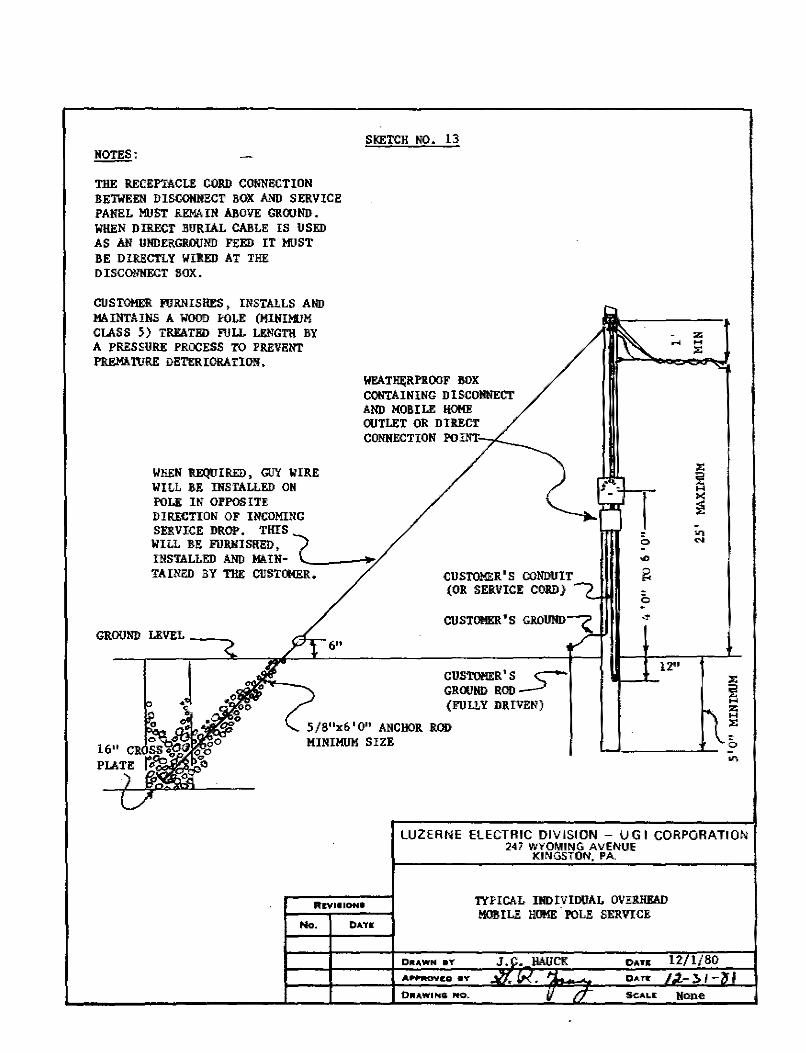
~:
THE RECEP'rACLE CORD CONNECTION BETWEEN DISCOIINllCT BOX AND SERVICE PANEL MUST REMAIN ABOVE GROOND. WHEN DIRECT BURIAL CABLE IS USED AS AN UNDERGROUND FEED IT MUST BE DIRECTLY WIRED AT THE DIS CONNECT BOX.
CUSTOMER FURNISHES, INSTALLS AND Mi\INTAINS A WOOD POLE (MINI1'1JM CLASS 5) TREATED FULL LENGTH BY A PRESSURE PROCESS TO PREVENT PREMATURE DBTERIORATION.
lll!EN REQUIRED, GUY WIRE WILL BE INSTALLED 011 POLE IN OPPOSITE DIRECTION OF INCOMING
SKETCH NO. 13
WEATl!f;RPROOF BOX CONTAINING DISCONNECT AND MOBILE HOKE OUTLET OR DIRECT CONNECTION POINT, 7'"--
SERVICE DROP. THIS ( WILL BE FURNISHED, INSTALLED AND Mil.IN- '----~" TAINEO BY THE CIJSTOH&R.
GROUND LEVEL __ _
CUSTOMER'S CONDUIT (OR SERVICE COID)
CUSTOMER'S C-GROIJIID ROD __J {FULLY DRIVEN)
5/8"x6'0" ANCHOR ROD MINIMUM SIZE
I 0
z ... H
;,:
12°
-·----~~ 0
"'
LUZERNE ELECTRIC DIVISION - VG I CORPORATION 247 WYOMING AVENUE
Rn-1•10N•
No. CATIE
D1tAWN aY
OIi.AWi l'tG NO.
KINGSTON. PA
1YPICAL IIIDIVIDIJAL OVERHEAD MOBILE HOME.POLE SERVICE
DAYS
DAff
SCALE Hone
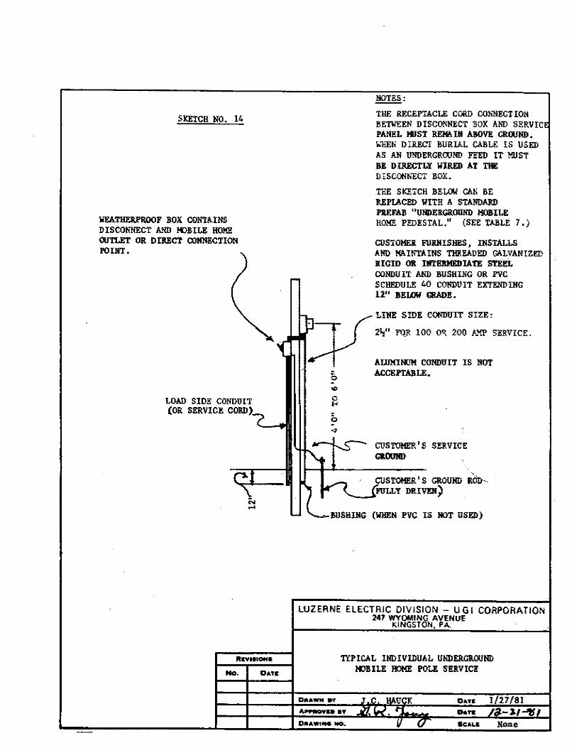
SKETCH NO. 14
WEAT!WU'ROOF BOX CONTAINS DISCONNECT AlllJ K>BILE HOME OUTLET OR DIRECT CONNBCTION POUIT.
LOAD SIDE CONDUIT (OR SERVICE CORD)
ND.
NOTES:
THE RECEPTACLE CORD CONNECTION BETWEEN DISCONNECT BOX AND SERVIC PANEL MUST REW.. Ill ABOVE GROOND. WHEN DIRECT BURIAL CABLE IS USED AS Ali UllDERGROOIID FEED IT MIJST BE DIRECTLY WIRED AT THE DISCONNECT BOX.
THE SKETCH BELOW CAN BE REPLACED WITH A STANDARD P1!EFAB "UllDERGROUND MOBILE HO!IE PEDESTAL." (SEE TABLE 7.)
CUSTOMER FIJRHISHES, INSTALLS AHO MA.INTAINS THREADED GALVANIZED RIGID OR INTEl!MEDIATE STEEL COIIDUIT AND BUSHING OR PVC SCHEDULE 40 CONDUIT EXT!!NDllfG 12" BELOW GRADE.
LIHE SIDE COffllUIT SIZE:
. ~n,~t ( 2~" FO..R 100 OR 200 AMP Si!RVICE.
~ AIJJMIIIJM CONDUIT IS NOT
DATIi:
0 ACCEPTABLE.
CUSTOMER'S SERVICE GR.OU!ID
CIJSTOMl!R' S GROUllD RciJ>.'-.-JiFULLY DRIVD}
(WHEN PVC IS HOT USED)
LUZERNE ELECTRIC DIVISION - UGI CORPORATION 247 WYOMING AVENUE
Dt1AWN 9T
KINGSTON. PA.
TYPICAL INDIVIDUAL UNDERGllOONll !«)BILE HOME POLE Sl!RVICI!
DATIi
A-PPlllOYaO aY O&n
SCALI:
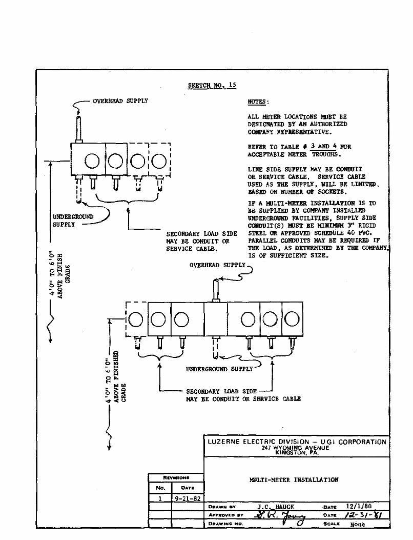
SKETCH NO. 15
) OVEIU!FAD SUPPLY ~:
ALL METER LOCATIONS !IJBT BE DESIGNATED BY Ali AUTHORIZED COMPANY UPIIESENTATIVE • . -,--~
l I
0 0 O:O: REFE!l TO TABLE # 3 Alm 4 FOR ACCEPTABLE Ml!TER TROOGHS.
..,....,~-- ,-,-4-,;.,r'-c, ~ r:u rr ~ u LINE SIDE SUPPLY MA.Y BE CONDUIT OR SERVICE CAJLE. SERVIC!! CABLE US!I> AS THE SUPPLY, WILL BE LIMITED, BASED ON HUMBER 01' SOCKETS.
Ll '----- .... ----) UNDERGRDU~ SUPPLY ~
IF A !IJLTI-Ml!TER INSTALLATION IS TD BE SUPPLIED BY COMPANY INSTALLl!D lllillERGROOND FACILITIES, SUPPLY SIDI! L
r-
SECOHDAilY ~ SIDE MAY BE CONDUIT OR SERVICE CABLE.
cotlDUIT(S) 111ST BE MIHIMUM 3" 11.IGID STl!EL OR APPROVED SCIIEOULE 40 PVC. l'AIALLEL CONDUITS MAY BE RJ!SiUillID IF Tl!E lMD, AS OETERMI!lEI) BY THE COMPANY, IS OF SUFFICIENT SIZE.
0\1E~-+ SUPP~Y)
lO O O 000 [ L'a 11 11 1T l ll ~ =~ ~ u~ T ~ ~ ~... L UNDERGROUND SUPPLY ) t Z:,· ~ ~ SECOHDAilY LOAD SIDE _J :0. ~ <> MAY BE CONDUIT OR SERVIC!! GAJILE
'
RIIY .. fON•
No. DATIi
1 9-21-82
LUZERNE ELECTRIC DIVISION - UGI CORPORATION 247 WYOMING AVENUE
KINGSTON. PA.
!t!LTI-METER INSTALLATIOlf
DttAwN ev J.C. HAUCK DAT& 12/ 1/80
DIIU,WING- ttO. f ( J
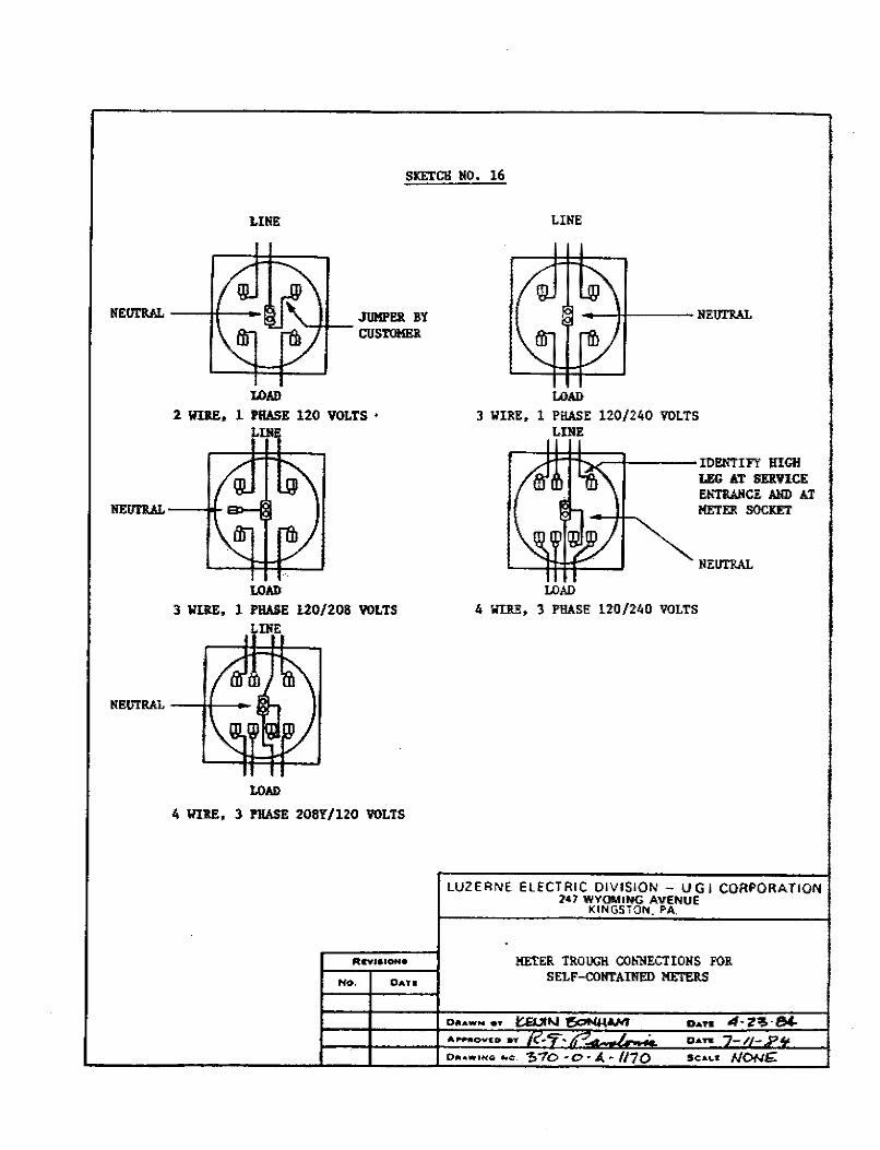
SKETCH HO. 16
LINE
LOAD
2 WIRE, l PHASE 120 VOLTS • LIii
LOAD 3 'WIRE, 1 PHASE U0/208 VOLTS
LOAD
4 WIRE, 3 PIIASE 208Y/120 VOLTS
No. DATI
LINE
LOAD
3 WIRE, 1 PHASE 120/240 VOLTS LiliE
t-:::1::f=l~::=+---IDENTIFY HIGH
LOAD
LEG AT SERVICE El!TlilfCE AND AT HETER SOCKET
4 WllE, 3 PHASE 120 /2'40 VOLTS
LUZERNE El ECT RIC DIVISION - U G I CORPORATION 247 WYOMING AVENUE
0#1.AWN .,..
KINGSTON. PA.
METER TROUGH CONNECTIONS FOR SELF-COIITAINED METERS
ill,~ovt:D aY
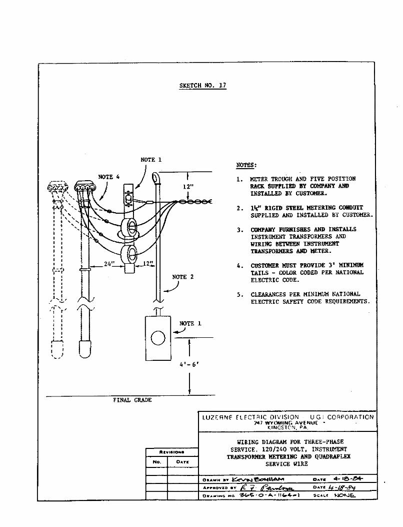
• .,.. - .,l ·,--r I ' I ' I ' I ' ' . l I
.I''.,!./ .. , .... .I
' 1 t ' . ' 1 ' . ' I ! I ' . -' I
' I
SKETCH NO. 17
NOTE l
NOTE 2
__)
NOTE 1
0 _.)
I ,4 ·- 6'
l FINAL GRADE
llll"WlalON•
No. 0.ATI(
NOTES:
1. METER TROUGH AIID FIVE POSITIOlf RACK SUPPLIED BY COMPANY AND INS'l'ALLED BY CUSTOl!El!.,
2:. Iii;" RIGID STEEL METERING CONDUIT SUPPLIED AND INSTALLED BY C!ISTOl!ER.
3. COMPMlY F!llt!USBES AIID INSTALLS INS'l'1UJMEIIT TIWISFOI!HERS AND WIRING BETIIEEN INSTRUMENT Tl!ANSFOBMEltS AIID METER •
4. CUSTOMER MUST PROVIDE 3' MINIMlJM TAILS - COLOR CODED PER NATIONAL ELECTRIC CODE.
5. CLEARANCES PER MINIMUM NATIOIIAL ELECTRIC SAFETY CODE REQUIREMENTS •
LUZf.R!\!f flECTAIC OIVISIOl\l UGI CORPORATION :t,41 WYOMING AVENU( •
KINGSTON. PA.
WIRING DIAGRAM FOR THREE-PHASE SERVICE, 120/240 VOLT, INSTRUMENT
Tl!AIISFORMER METERING A!ID QUADRAPLEX SERVICE WIRE
0A.TC -/.
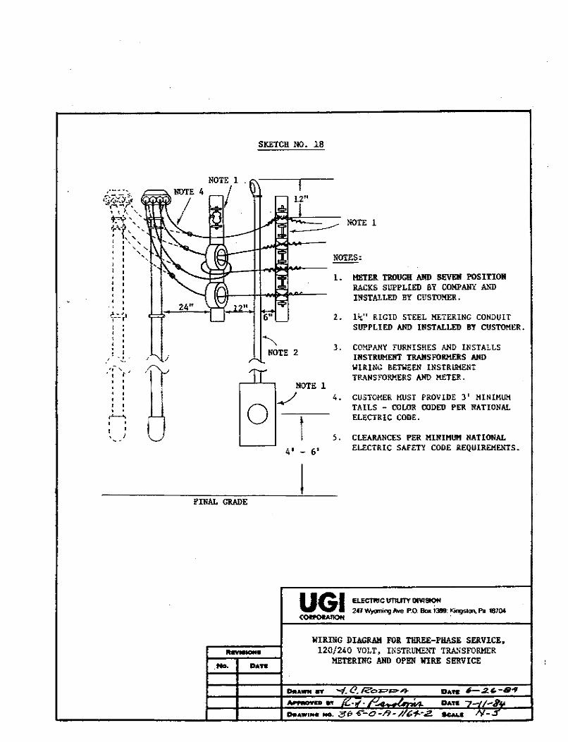
.. ' , I i'.,
• • ,...._.,
' }
SKETCH NO. 18
~
1.2"
NOTES: ----1. HETER TROUGH AND SEVEII POSITION l!ACKS Slll'PLIED BY OOMP.MIY AND INSTALLED BY CUSTO!IEll •.
2. ll,;" RIGID STEEL METERING CONDUIT SUPPLIED AIID INSTALLED BY CUSTOMER.
NOTE 2 J. COMPANY FURNISHES AIID Ill STALLS
ll'lSTRUMENT TRAIISFORHERS AIID WIRING BETWEEN INSTRUMENT TRANSFORMERS AN!) METER.
NOTE 1 4.
0 ../
l CUSTOMER MUST PROVIDE 3' MINIMUM TAILS - COLOR CODED PER NATIONAL ELECTRIC CODE.
FINAL GRADE
111n:111cr11
s. 4' - 6'
CLEARANCES PER MIIIIHUM NATIONAL ELECTRIC SAFETY CODE REQUIREMENTS.
!
WIRillG DIAGRAM FOR THREE-PHASE SERVICE, 120/240 VOLT, INSTRJJMENT TRANSFORMER
METERING AND OPEN WIRE SERVICE
..1W i4i04D 91'
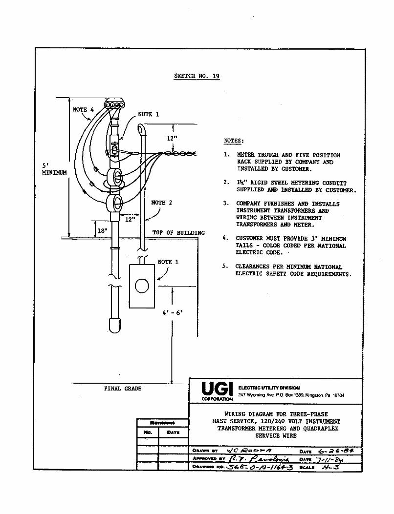
5' MDHMIJM
1211
18 11
FINAL GRADE
No.
SKETCH NO. 19
1211
NOTES:
1. METER TROUGH AND FIVE POSITION RACK SUPPLIED l!Y COMPANY MID INSTALLED BY COSTOMEII..
2. lit" RIGID STEEL MlITERllfG CONDUIT SUPPLIED AND INSTALLED BY ClfSTOHER.
3. COl!PAlfY FUJalISHES AND IllSTALLS IIISTRUKEIIT TIIANSPORHERS AND WIRING JIE'I'WEEN INSTRtmENT TRANSFORMERS AllD HETER.
TOP 01' BUIIDING
4' - 6'
4. CUSTCf(Ell. MUST PIIOVlDE )' MillIMlll! TAILS - COLOR CODED PER ·IIATIONAL ELECTRIC CODE.
~. CLEARAlfCES PER MINIMIM IIA?IONAL ELECTRIC SAFETY CODE REQlflREl!EIITS.
UGI ELECTRICIITIUTVIIMSIOH .247 Wyoming !we. P.O Ek:P: lJ89_ Kingsaon. Pa 1870t
COIIPOU.TION
WIRING DIAGRAM FOR THREE-PHASE l!AST SERVICE, 120/240 VOLT INSTRUMENT
TRANSFORMER METERING MID .QUADRAPI.EX SERVICE WIRE
0 ....
~DeY DAN
°""·- -..::5'"6~ t,-/'1-//,,t.-;3 9CAUI
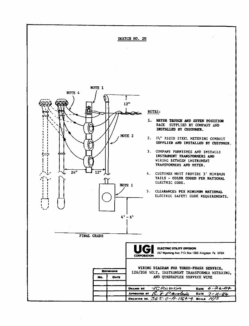
• t---~· I I I I I I I I • I 1 I .I""' I., . -
,.- ..... J
'I t • I I I I I I I I I • • ,.._.,
I • I I ...... ,,,
SKETCH NO. 20
FINAL GRADE
llffllllONI
No. DAff
t 12"
41 - 6'
~· 1. METER TROUGH AND SEVEN POSITION
RACK SUl'PLilID BY COMPMIY AND IllSTALLED BY CIJSTOMER.
2. lit." RIGID STEEL !1£TEl!111C CONDUIT SUPPLIED AlID INSTALLED BY CUSTOMER.
3 .
4 •
).
UGI
COMPANY FURNISHES AND INSTALLS lNSTRIRIENT TRAIISFORKERS AND WIRING BETIIEEN INSTRUMENT TRANSF0R!l£RS AND HETER.
CUSTO!IER HUST PROVIDE 3' llINil!Ull TAILS - COLOR CODED PER NATIONAL ELECTRIC CODE.
CLEARANCES PER l!INIHI.IM NATIONAL ELECTRIC SAFETY CODE REQUII\El!EllTS •
ELE<m!IC UTIU1Y OMSIOff 241 ~ !we. P.O Box 1389. Kingst~. Pa 18704
WllllllG DIAGRAM FOR T!ll!EE-l'HASE SERVICE, 120/208 VOLT, INSTRUMENT TRANSFORMER METERING,
AND QUADRAPLEX SERVICE WIRE
4.. raouu n .... AWIMe -· 060-C)-/)-//t;:1--1-
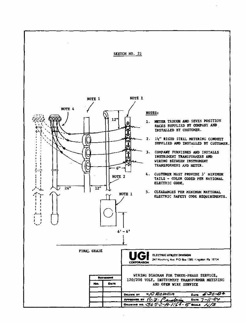
' '
• I I •
) - .. , ,··1 ' I
' ' ' I : ' ,~-J.· ' . "''• ... , , ... I I
i ' ' . 0 I
,L-,
' I ' I "
NOTE 1
I
24"
-
SKETCH NO. 21
NOTE l
NOTE 2
NOTE 1
4' - 6'
llOTl!S:
1, MEnll TJUlUGH Alll> Sl!VEll POSITION RACKS SUPPLIED BY COMPANY Alll> ~ INSTALLED BY CUSTOMER.
2. l"" RIGID STEEL HETERIIIG CONDUIT SUPPLIED Alm IIISTALLED BY CUSTOKER.
3. COKPAIIY FllDISllES AlID INSTALLS IIISTRIJMENT 1'UIISFORMERS AlID WIRING BETIIEEII INSTRUMENT 1'UIISFORMERS A11D !IETER.
4. CUSTOHD. MUST PROVIDE 3' HIIII.Kl.JH TAILS - COLOR CODED PER NATIONAL ELECTUC CODE.
5. CLEARANCES PER: MIIIIHIIM NATIONAL ELECTJUC SAFETY CODE REQUIREHEll7S.
WIRING DIAGRAM FOR THREE-PHASE SERVICE, 120 /208 VOLT, IHSTR!JMEliT TRAHSFOBMER METERI!iG
AHD OPEii WIRE SERVICE
k i AUii .. aY
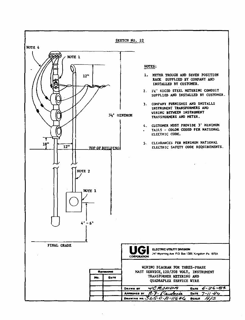
NOTE 4
18" 12"
NOTE 2
~.LL-NOTE l
01-
FINAL GRADE
SKETCH NO. 22
1 NOTES:
1. METER TROUGH AND SEVEN POSITION RACK SUPPLIED RY COMPANY AND IHSTALI.ED BY CUSTOMER.
2. llr:" RIGIO STEEL !IETERIIIC CONOUIT SUPPLlEI> AND ll!STALLE!) BY CUSTOHER.
51:i' IIINIMUM
l. COKP AN1 Fllltlll SHES AND INSTALLS UISTRI.NEIIT TIWIS.fORHD.S AND WlRIIIG B&nlEDI IMSTRIIIEIIT TRA.~SFOltltERS AJIO HETER.
4. CIJSTOHER MUST PROVlllE )' KINIHUH TAll.S - COLOR COD£1> PER NATIONAL ELECTRIC CODE.
5. CUARAIICES ru HIN lHUH NA TlON AL ELECTR{C SAFETY COllE REQUlREHEHTS.
UGI COltl'OUIION
ELECTRIC untnY DM-2«1 Wyornit'Q Ave. P.O b 1389." KingSllon Pa 18704
11.nalC:ffS
lflll!IG DIAGRAM FOR THREE-PHASE MAST SERVICE, 120/208 VOLT, INSTRUMENT
TRANSFORMER HE1'EIUNC ANO QUADRAPLEll SERVICE WIRE
No. DAff
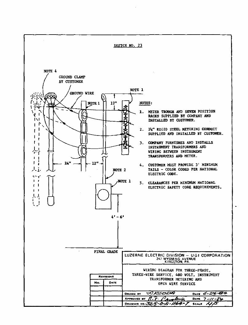
.,,~:: -\ f{-: 1:~t I~..\-'. I -~"'i'"" \ I "\
i I I'\ I
NOTE 4
I I'' I I
I I I
L-~ 'r·r I I I : I • ,,.. ... 1~
....... < I r I I I I
I_J •
' I '-·
GROUIII} CLAMP BY CUSTOMER
SKETCH NO. 23
NOTE 1
12"
NOTE 2
/ NOTE 1
4' - 6 1
NOTES:
l. METER TlOUGR MID SEVEN POSITION BACKS SUPPLIED BY COMPANY AND INSTALLBD BY CIJSTOIIER.
2. l\" IUGIO STEEL METERING CONDUIT Slll'PLIEO ANO IIISTALJ.EI) BY CUSTOIIER.
J. COl1PANY FUltl!ISHES ANO IIISTALLS IIISTRlR!EliT TRAJISFOl!MUS ANO li'IIUIIC BETIIEEli lllSTlUJMENT TRAJISFOl!IIEJ1.S Allll HETER.
4. CUSTONElt MUST PROVIDE 3' MINIMUM TAILS - COUll!. CODED PER NATIONAL ELECTUC COOE •
S. CLEABAIICES PER MINI.MU!{ NATIOIIAL ELECTRIC SAFETY CODE REQUIRE!IEIITS.
FINAL CRADE
No. D,1,n
LUZERNE ELECTRIC DIVISION - UGI CORPORATION 247 WYOMtNG AVENUE
KINGSTON. PA.
WIRING DIAGRAM FOR THREE-PHASE, THREE-WIRE SERVICE, 480 VOLT, IIISTRIJMElIT
TRANSFORMER METERING AND OPEN WIRE SERVICE
0.AWN 8Y
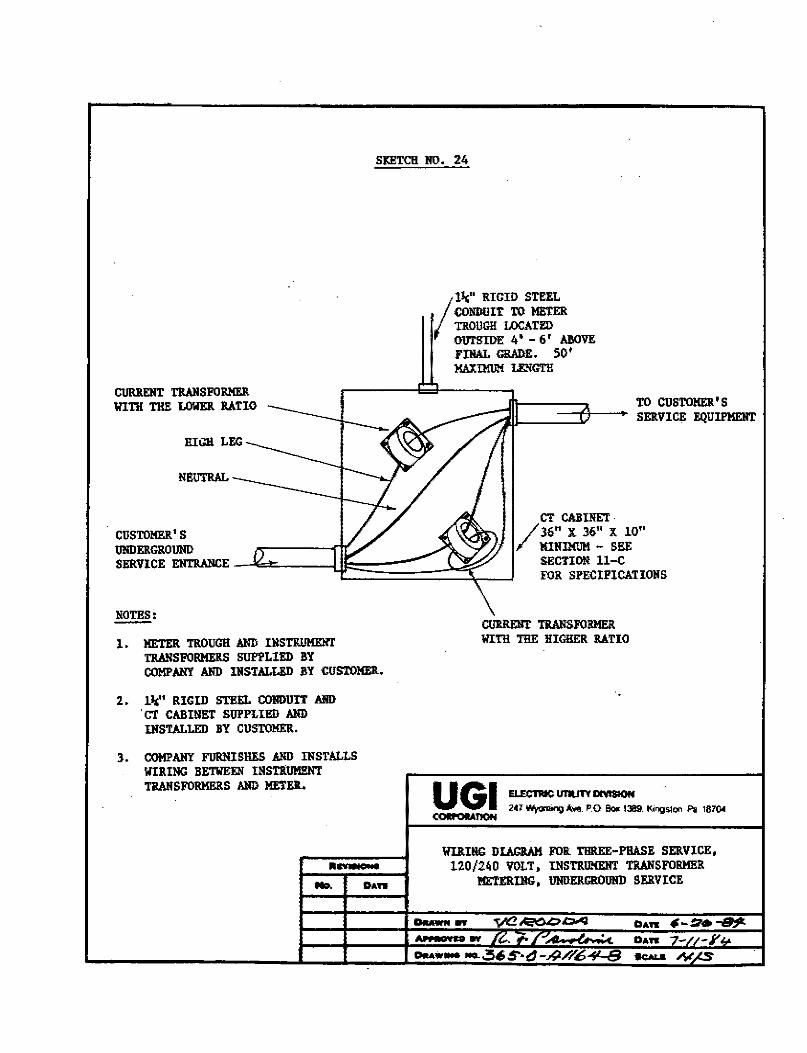
SKETCH NO. 24
CURRENT TIWISFORMER WTI'!I THE LOWER RATIO
NEUTRAL
NOTES:
1. METER TROUGH AND IlfSTIWMEIIT TIWISFOl!MERS SUP1'LIED BY COMPANY AND INSTALLED BY CUSTOMER.
2 • 1~' RIG ID STEEL COR!lUIT AIID ·er CABINET SUPPLIED AllD IlfSTALLED BY CUSTOMER.
3. COMPANY FURNISHES AND INSTALLS WIRING BETWEEN INSTRUMl!IIT TIWISFORMERS A11D METER.
•ns11a11a - .......
/
ll,;" RIGID STEEL CO!IDllIT TO METER TROUGH LOCATED OUTSIDE 4' - 6' Al!OVF. FINAL GRADE. 50' MAXIMUM L&l!GTH
ClllffiENT TRANSFORMER WITH THE RICHER RATIO
TO CUSTOMER'S SERVICE EQUIPMENT
WIRIIIG DIAGRAM FOR THREE-PHASE SERVICE, 120/240 VOLT, INSTRU!!EIIT TRANSFORMER
METERING, IJHOERGROOIID SERVICE __ ..,
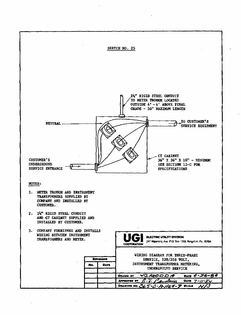
CUSTOMER'S UNDERGROUND SEIi.VICE EN'I'RMICE
~· 1, METER l'ROUGH AND IIISTRUMEIIT
Tlil!SF01\MERS SUPPLIED l!Y CQ!l>ANY AllD IlfSTALLE!> BY CUSTOMER.
2. 11(' RIGID STEEL CONDUIT AND CT CABINET SUPPLIED AllD INSTALLEO BY CUS'l'OMER.
3. COMP ANY FURNIS!li!S AND INSTALLS WIRING BETWEEN llfSTRUMEIIT TRANSFORMEl!S MID METER.
....... NidJI
No.
SKETCH NO. 25
lli;" RIGID STEEL CONDUIT TO METER TROUGH LOCATED OUTSIDE 4' - 6' A!IOVl'. :Fil!AL GRADE - 50' MilillllM LEIIG'fB
-=====D~ro CUSTOMEJt's - SERVICE EQUIPMEll'f
CT CABlllET 36" X 36" X 10" - HDIIl!llM SEE SECTION ll-C FOR SPECIFICATIOlfS
WIRil!G DIAGRAM FOR TIIREE-Pl!ASE SERVICE, 120/208 VOLT,
INSTRUMEHT TRANSFORMER METERING, UNDERGROUND SERVICE
DIIAWN ff
.Auraoua ff
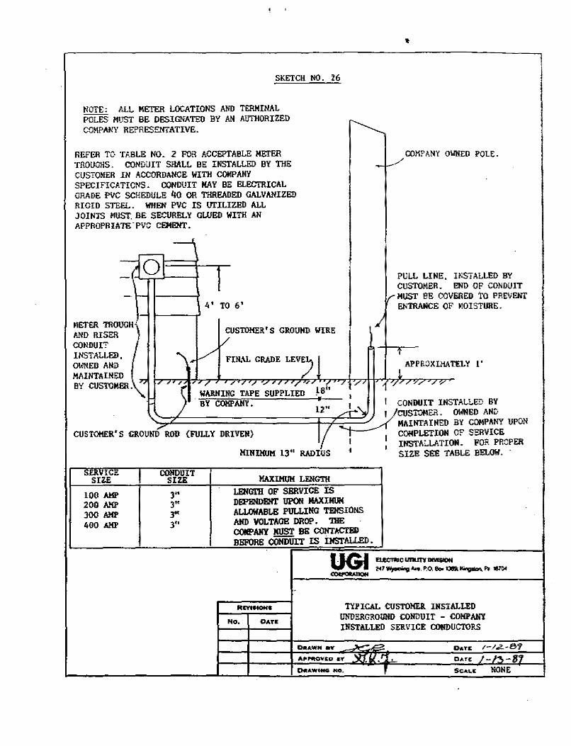
SKETCH NO. 26
NOTE: ALL METER LOCATIONS AND TERMINAL POLES MUST BE DESIGNATED BY AN AUTIIORIZED
~ COMPA~'Y REPRESENTATIVE.
REFER TO TABLE NO. 2 FOR ACCEPTABLE METER _.../COMPAflY OWNED POLE. TROUGllS. CONDUIT SHALL BE INSTALLED BY TIIE ~
CUSTOMER IN ACCORDANCE WITH COMPANY SPECIFICATIONS. CONDUIT MAY BE ELECTRICAL GRADE PVC SCHEDULE /jO 00 THREADED GALV.o.NIZED RIGID STEEL. WHEN PVC IS !Tl'ILIZED ALL JOINTS MUST. BE SECURELY GLUED WITH AN APPROPRIATE.PVC CEMEHT.
-;f<51 1 PULL LINE. INSTALLED BY CUSTOMER. END OF CONDUIT
-· .._ - MUST BE COVllllED to PREVENT 4' TO 6' ENTRANCE OF MOISTURE. ,_
METER TROUGH CUSTOMER' S GRO!JII]). IIIRE
,I AND RISER CONDUIT
/ INSTALLED. ...,. ~ FIN.\L GRADE / l t
0\/NED AND APPROXIMATELY I' MAINTA !NED
77 1
BY CUSTOMER.\. ., , /c ,,, / ., ., / , . / . ., ,, , _, ., // . ~ / '/• ,~/"""'"//1/
. WARNING TAPE SUPPLIED 18" 1
J BY COMPANY. . I I CONDUIT INSTALLED BY
' 12" ~CUSTOMER. OWNED AND
.,... I
MAINTAINED BY COMPANY UPON CUSTOHER'S GROUND ROD {FULLY DRIVEN} COMPLETION OF SERVICE
I : INSTALLATION. FOR PROPER MINIHUM 13" RADIUS ' SIZE SEE TABLE BELOW. ·
~=•ICE CONDULT MAXIMUM LENGnl SIZE SIZE
100 AMP 3" LENGTH OF SERVICE IS
200 AMP 3" DEPENDENT UPOI'! JIAXIMlll(
300 AMP 3" AIJ.OWABLE PULLING TENSIONS
400 AMP 3" AND YOLTAOB DROP. 'l1lE COMPANY MUST Bil CONTACTBII BBl'ORE CONDUIT IS IJISTALUID.
UGI a.smacununDMSIOH z.«1~ Awe. P.O. lb. 135.~ Fa. 11104 ---
R..,._ TYPICAL CUSTO!!Ell INSTALLED
No. OATE lJl!DERGROllNO COIIDUIT - COMPANY INSTALLED SERVICE COIIDUCTORS
0.A.WN eV .
DATE /-/.Z.·8'7
APNOVEO •Y '\n, u., ' . 0AT"E: /-f,-1rf Cl«A.WCMG HO. Sc.<1.• NONE


![User Manual Three Phase Energy Meter - INOGATE Manual Three Phase Energy Meter HXE310 CT & CTPT Meter Hexing Electrical Co., Ltd. [2013.3] Meter User Manual-HXE310 2 / 76 Introduction](https://img.pdfslide.net/doc/110x75/5aa750e17f8b9a50528c3353/user-manual-three-phase-energy-meter-manual-three-phase-energy-meter-hxe310-ct.jpg)