Embed Size (px)
Citation preview
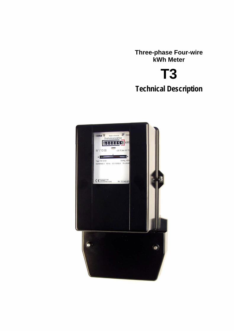
Three-phase Four-wire
kWh Meter
T3 Technical Description
T3 Technical Description
CONTENTS
1. APPLICATION........................................................................................................4
2. RATINGS................................................................................................................4
3. METER TYPE DESIGNATION ...............................................................................4
4. METER CONSTRUCTION......................................................................................5
4.1. METER BASE...................................................................................................6 4.2. METER COVER ...............................................................................................6 4.3. TERMINAL BLOCK ..........................................................................................6 4.4. TERMINAL BLOCK COVER.............................................................................6 4.5. ELECTROMAGNETS.......................................................................................6 4.6. FRAME .............................................................................................................7 4.7. BRAKE MAGNET .............................................................................................7 4.8. ROTOR.............................................................................................................7 4.9. UPPER BEARING ............................................................................................7 4.10. LOWER BEARING ........................................................................................7 4.11. REGISTER ....................................................................................................8 4.12. REVERSE RUNNING STOP .........................................................................8
5. METER ADJUSTMENTS........................................................................................8
5.1. ADJUSTMENT ELEMENTS .............................................................................9
6. TECHNICAL DATA ..............................................................................................10
7. CONNECTION DIAGRAMS..................................................................................11
8. OVERALL METER DIMENSIONS........................................................................12
3/13
T3 Technical Description
1. APPLICATION
The electricity meters types T3... are intended for measuring active energy for direct connection in three-phase four-wire networks at balanced or unbalanced load. They are usable indoors or outdoors mounted into the cabinet, for operation in closed cabinets of IP-53 protection class (acc. with - IEC 60529), and under cold and average climatic conditions (acc. with - IEC 60721-2-1), when air is free of aggressive vapours and gas, and air relative humidity does not exceed 95 %.
2. RATINGS
The meter performance and the measuring-technical characteristics comply with Directive on Measuring Instruments (MID) 2004/22/EC, Annex MI-003 – Active Electrical Energy Meters, Annex H1, article 4 and with MID belonging standards EN 50470-1 and EN 50470-2, for accuracy class A, electromagnetic environments E2, mechanical environments M1 and climatic environments for temperature range from -25 to +70°C. They are also in accordance with previously valid international standards IEC 62053-11, IEC 62052-11, and also, IEC 521, IEC 60521, VDE 0418, for accuracy class 2.
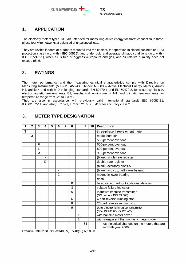
3. METER TYPE DESIGNATION
1 2 3 4 5 6 7 8 9 10 Description T three-phase three-element meter 3 model number E 500-percent overload F 600-percent overload L 800-percent overload M 900-percent overload - (blank) single-rate register D double-rate register - (blank) accuracy class A - (blank) two cup, ball lower bearing 2 magnetic lower bearing - dash 0 basic version without additional devices 3 voltage failure indicator 5 inductive impulse transmitter
(SO output - DIN 43 864) 6 4-part reverse running stop 8 24-part reverse running stop 9 opto-electronic impulse transmitter
(SO - DIN 43 864 or RELAY) 1 with bakelite meter cover 2 with transparent thermoplastic meter cover S1 technological changes on the meters that are
tied with year 2006 Example: T3F-01S1, 3 x 230/400 V, 0.5-10(60) A, 50 Hz
4/13
T3 Technical Description
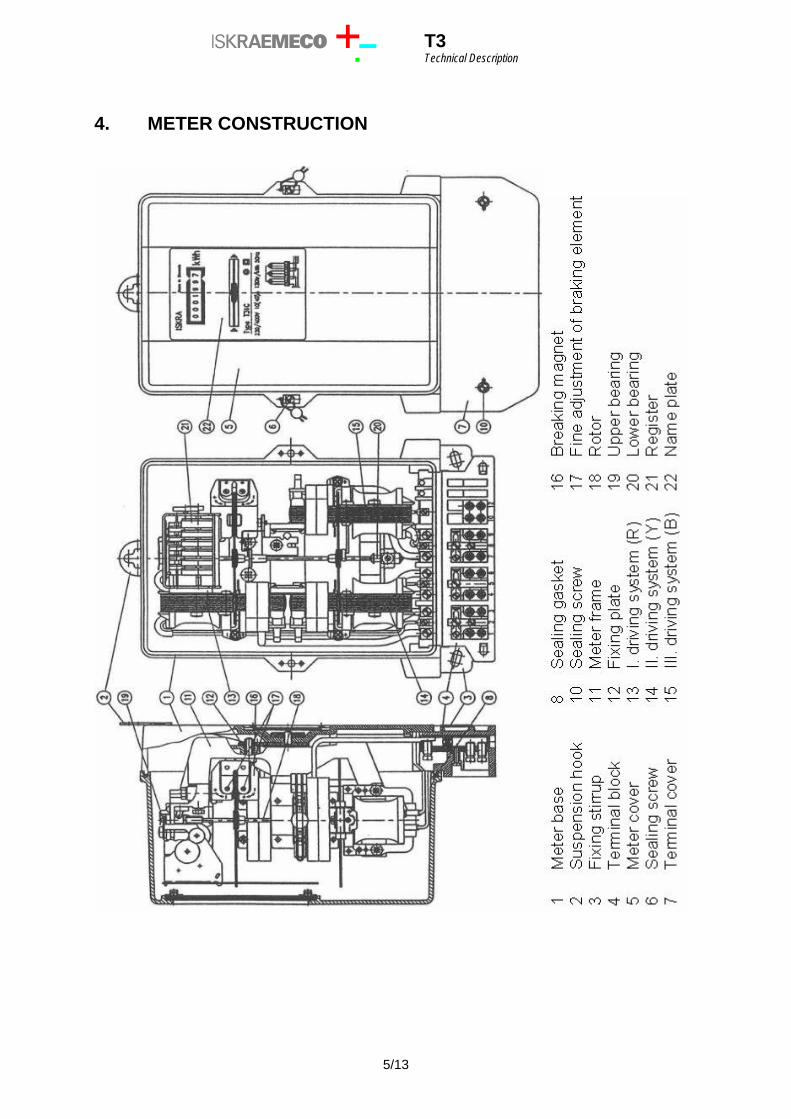
4. METER CONSTRUCTION
5/13
T3 Technical Description
4.1. METER BASE
It is made of bakelite, highly resistant to creep current. A suspension hook is fastened to it. It allows different affixing dimensions of the meter with a screw outside the case or under it. The holding stirrup on the lower part of the base is fastened to it with a pin, connecting the base with exchangeable terminal block. The fixation of the meter frame into the meter base is performed by means of the bakelite base pillars. With the new way of fixation the elasticity of the meter frame in the connection with the bakelite base is still ensured by the same intermediate carrying fixing plate.
4.2. METER COVER
It is made of bakelite or transparent thermoplastic material. Bakelite cover has a glass window at the front side. The window is sealed with silicon sealant from the internal side and is fastened with self-locking elastic washers. The cover is fastened to the base with two sealing screws so that better sealing between the cover and the base is attained. During the calibration the covers can be hanged on the meter base without screwing. Transparent cover is made of transparent die-cast thermoplastic material, resistant to shocks, and strengthened with concave ribs on the inner side also for protection of UV radiation. The cover is fastened to the base with two sealing screws, so that sealing is possible irrespective of the position of the terminal block cover. In the cover rabbet there is a solid rubber gasket meeting all dust-proof requirements, and enabling the cover to be smoothly placed on the base. During the calibration the cover can be hang on the meter base.
4.3. TERMINAL BLOCK
It is fastened to the base in notches and stuck into the hanger from the lower side, so that access to the interior of the meter is not possible when the cover is on. Terminals are embedded in a bakelite framework. For main circuits of T3 meter type, the terminals holes for meters up to 60 A have a diameter 6.5 mm, which is enough for connection of outer wires of 25 mm2, and for meters up to 120 A have a diameter 8.5, 9.5 or 10.5 mm (35 or 50 mm2). The terminals for connection of auxiliary circuits have the holes of diameter 3.2 mm. The flash-over and creep distances in the bakelite framework, between metal parts of individual circuits on one hand, and terminals and outside contact parts on the other, are large enough to assure high breakdown strength.
4.4. TERMINAL BLOCK COVER
It is made of solid, self-extinguishable, thermoplastic or duroplastic material. It can be supplied in short, middle or extended version. With the short terminal cover version, the connection terminals are protected against undesired access, while with the version with middle and extended cover the access is prevented also to the suspension hook. Sealing of both sealing screws can be performed independently of sealing the kWh-meter cover.
4.5. ELECTROMAGNETS
The meter employs three similar electromagnet elements which are mounted on a robust die-cast frame. Two elements drive the lower disc and one the upper disc on which the brake magnet operates. The voltage electromagnet of each element has a double magnetic circuit and the current electromagnet is of U form. Electromagnetic sheet of a corresponding initial permeability in current cores assures specified error curves with respect to the load, either at small loads or overloads. Electromagnetic sheet metal for laminations of voltage and current cores as well as for other parts has been previously selected by uniform electric magnetic characteristics.
6/13
T3 Technical Description
4.6. FRAME
For the drive systems and the brake system a pressure-injected SiAl casting of high physical strength and endurance is applied. The framework is fastened with two screws to the base through an adapter which unloads the bakelite base, and makes the measuring system elastic. In the framework place is left for the impulse transmitter to be built-in.
4.7. BRAKE MAGNET
It effects on the upper disc of the rotor. The brake magnet is constructed with a formed steel magnet frame. The magnetic cubes, made of AlNiCo VIII material, are fastened on the frame by gluing. There is additional thermo-compensation plate glued to the side of the magnet cube, which ensures low external temperature and the meter self-heating influence on the accuracy curve along the whole of the operation temperature range. The coarse error adjustment of the meter is enabled through acting on the brake magnet, by shifting it across the radius of the rotor disk. The fine adjustment device in form of a special adjusting plate is fixed on the magnet frame. This plate acts as a magnetic flux shunt and can be shifted by means of a standard screwdriver. The positive and negative directions of adjustment are marked on the same plate.
4.8. ROTOR
It is made from aluminium sheet selected for its conductivity and purity. It is free from particles of ferrous metal. The meter rotor is relatively light-weight, circular, 100 mm in diameter and 1 mm thick, die-cast with aluminium alloy to a stainless steel shaft. The disc has a mark which helps count the revolutions on the disc for testing purposes. The register is driven by a moulded worm, made of polyamide, which is fitted to the shaft. A graphite sleeve is impressed into the worm on the upper side of the shaft.
4.9. UPPER BEARING
It is a pin type and serves as an axial rotor guide. A pin made of stainless steel spindle smoothly slides in the upper bearing. The pin is pressed into the brass sleeve. A sleeve with the pin is fastened to the meter frame. The bearing has exceptionally small and time constant friction and should not be lubricated.
4.10. LOWER BEARING
It is of two-cup or magnetic type. The two-cup bearing: Between two sapphire cups lies a polished steel ball, protected against corrosion by a thin layer of good quality oil. Initial friction is insignificant, and the bearing has a long life. The bearing assembly is fastened with spring to prevent damage during transportation, and to enable a simple exchange of the rotor by pushing the bearing assembly only, without any readjustment. The magnetic bearing: The temperature compensated magnetic bearing has two magnetic parts with equally polarized adjacent surfaces. Due to the mutually repelling forces between the two magnetic surfaces and the rotor weight, the rotor magnet floats at a distance from the stator magnet. The rotor is guided by a highly polished spindle which projects from the lower part of the bearing into the upper part, its upper pin acting as an armature. The stainless steel spindle runs in a graphite bearing sleeve, making lubrication unnecessary.
7/13
T3 Technical Description
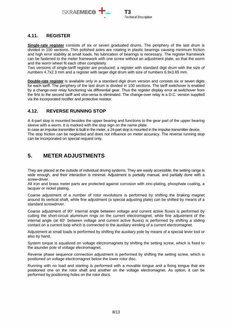
4.11. REGISTER
Single-rate register consists of six or seven graduated drums. The periphery of the last drum is divided in 100 sections. Thin polished axles are rotating in plastic bearings causing minimum friction and high error stability at small loads. No lubrication of bearings is necessary. The register framework can be fastened to the meter framework with one screw without an adjustment plate, so that the worm and the worm wheel fit each other completely. Two versions of single-tariff register are produced: a register with standard digit drum with the size of numbers 4.7x2.3 mm and a register with larger digit drum with size of numbers 6.9x3.65 mm. Double-rate register is available only in a standard digit drum version and consists six or seven digits for each tariff. The periphery of the last drum is divided in 100 sections. The tariff switchover is enabled by a change-over relay functioning via differential gear. Thus the register display error at switchover from the first to the second tariff and vice-versa is eliminated. The change-over relay is a D.C. version supplied via the incorporated rectifier and protective resistor.
4.12. REVERSE RUNNING STOP
A 4-part stop is mounted besides the upper bearing and functions to the gear part of the upper bearing sleeve with a worm. It is marked with the stop sign on the name plate. In case an impulse transmitter is built in the meter, a 24-part stop is mounted in the impulse transmitter device. The stop friction can be neglected and does not influence on meter accuracy. The reverse running stop can be incorporated on special request only.
5. METER ADJUSTMENTS
They are placed at the outside of individual driving systems. They are easily accessible, the setting range is wide enough, and their interaction is minimal. Adjustment is partially manual, and partially done with a screw-driver. All iron and brass meter parts are protected against corrosion with zinc-plating, phosphate coating, a lacquer or nickel plating.
Coarse adjustment of a number of rotor revolutions is performed by shifting the braking magnet around its vertical shaft, while fine adjustment (a special adjusting plate) can be shifted by means of a standard screwdriver.
Coarse adjustment of 90° internal angle between voltage and current active fluxes is performed by cutting the short-circuit aluminium rings on the current electromagnet, while fine adjustment of the internal angle (at 60° between voltage and current active fluxes) is performed by shifting a sliding contact on a current loop which is connected to the auxiliary winding of a current electromagnet.
Adjustment at small loads is performed by shifting the auxiliary pole by means of a special lever tool or also by hand.
System torque is equalized on voltage electromagnets by shifting the setting screw, which is fixed to the asunder pole of voltage electromagnet.
Reverse phase sequence connection adjustment is performed by shifting the setting screw, which is positioned on voltage electromagnet below the lower rotor disc.
Running with no load and starting is performed with a movable tongue and a fixing tongue that are positioned one on the rotor shaft and another on the voltage electromagnet. As option, it can be performed by positioning holes on the rotor discs.
8/13
T3 Technical Description
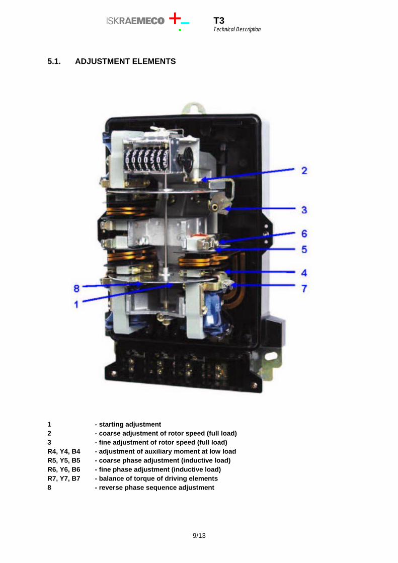
5.1. ADJUSTMENT ELEMENTS
1 - starting adjustment 2 - coarse adjustment of rotor speed (full load) 3 - fine adjustment of rotor speed (full load) R4, Y4, B4 - adjustment of auxiliary moment at low load R5, Y5, B5 - coarse phase adjustment (inductive load) R6, Y6, B6 - fine phase adjustment (inductive load) R7, Y7, B7 - balance of torque of driving elements 8 - reverse phase sequence adjustment
9/13
T3 Technical Description
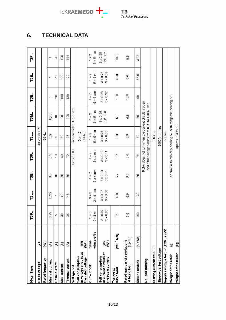
6. TECHNICAL DATA
10/13
T3 Technical Description
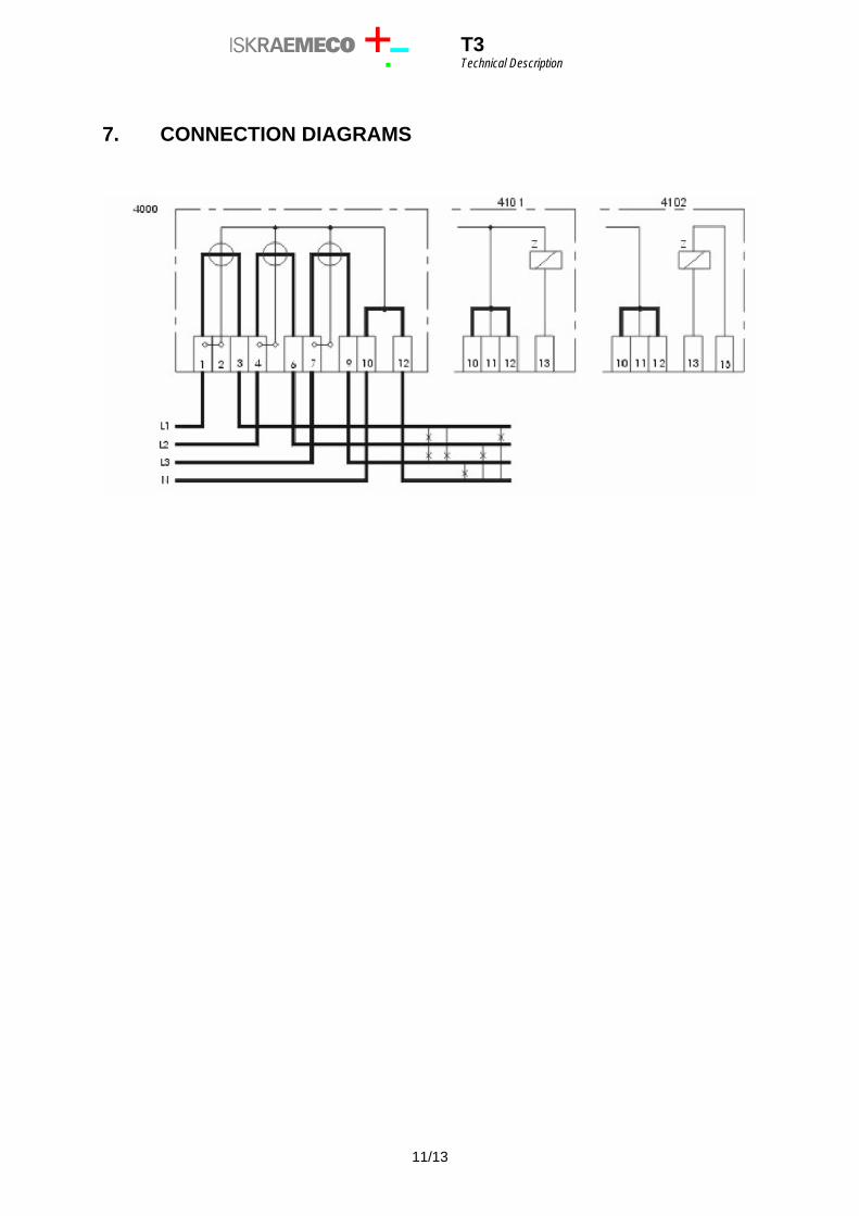
7. CONNECTION DIAGRAMS
11/13
T3 Technical Description
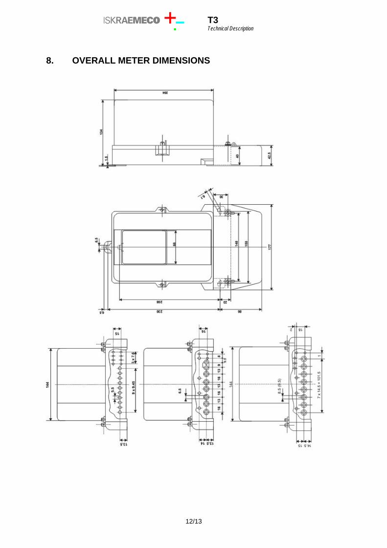
8. OVERALL METER DIMENSIONS
12/13

T3 Technical Description
Owing to periodical improvements of our products the supplied products can differ in some details from data stated in the Technical Description. ______________________________________________________________________________________________________ Iskraemeco, Energy Measurement and Management 4000 Kranj, Savska loka 4, Slovenia Telephone (+386 4) 206 40 00, Telefax: (+386 4) 206 43 76 Published by Iskraemeco, Marketing Data subject to alternation without notice. ______________________________________________________________________________________________________
13/13