Embed Size (px)
Citation preview
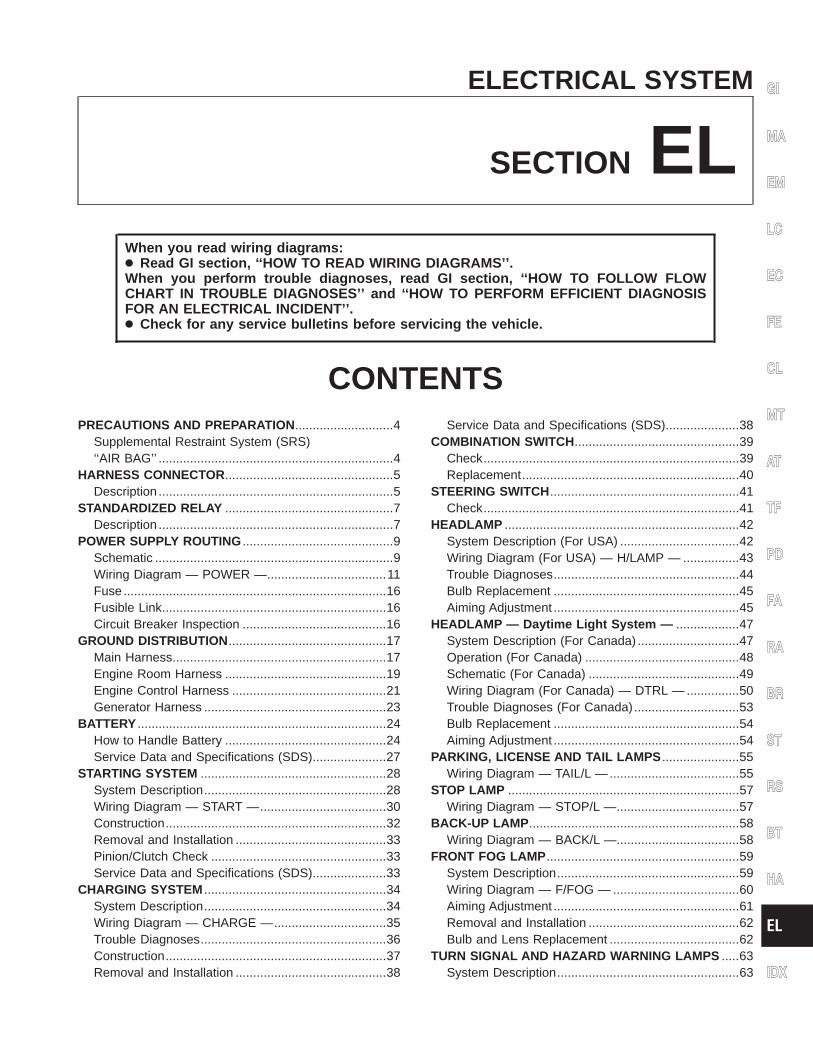
ELECTRICAL SYSTEM
SECTION ELWhen you read wiring diagrams:● Read GI section, ‘‘HOW TO READ WIRING DIAGRAMS’’.When you perform trouble diagnoses, read GI section, ‘‘HOW TO FOLLOW FLOWCHART IN TROUBLE DIAGNOSES’’ and ‘‘HOW TO PERFORM EFFICIENT DIAGNOSISFOR AN ELECTRICAL INCIDENT’’.● Check for any service bulletins before servicing the vehicle.
CONTENTSPRECAUTIONS AND PREPARATION ............................4
Supplemental Restraint System (SRS)‘‘AIR BAG’’ ...................................................................4
HARNESS CONNECTOR................................................5Description ...................................................................5
STANDARDIZED RELAY ................................................7Description ...................................................................7
POWER SUPPLY ROUTING ...........................................9Schematic ....................................................................9Wiring Diagram — POWER —..................................11Fuse ...........................................................................16Fusible Link................................................................16Circuit Breaker Inspection .........................................16
GROUND DISTRIBUTION .............................................17Main Harness.............................................................17Engine Room Harness ..............................................19Engine Control Harness ............................................21Generator Harness ....................................................23
BATTERY .......................................................................24How to Handle Battery ..............................................24Service Data and Specifications (SDS).....................27
STARTING SYSTEM .....................................................28System Description....................................................28Wiring Diagram — START —....................................30Construction...............................................................32Removal and Installation ...........................................33Pinion/Clutch Check ..................................................33Service Data and Specifications (SDS).....................33
CHARGING SYSTEM ....................................................34System Description....................................................34Wiring Diagram — CHARGE —................................35Trouble Diagnoses.....................................................36Construction...............................................................37Removal and Installation ...........................................38
Service Data and Specifications (SDS).....................38COMBINATION SWITCH ...............................................39
Check.........................................................................39Replacement..............................................................40
STEERING SWITCH......................................................41Check.........................................................................41
HEADLAMP ...................................................................42System Description (For USA) ..................................42Wiring Diagram (For USA) — H/LAMP — ................43Trouble Diagnoses.....................................................44Bulb Replacement .....................................................45Aiming Adjustment .....................................................45
HEADLAMP — Daytime Light System — ..................47System Description (For Canada) .............................47Operation (For Canada) ............................................48Schematic (For Canada) ...........................................49Wiring Diagram (For Canada) — DTRL — ...............50Trouble Diagnoses (For Canada)..............................53Bulb Replacement .....................................................54Aiming Adjustment .....................................................54
PARKING, LICENSE AND TAIL LAMPS ......................55Wiring Diagram — TAIL/L — .....................................55
STOP LAMP ..................................................................57Wiring Diagram — STOP/L —...................................57
BACK-UP LAMP ............................................................58Wiring Diagram — BACK/L —...................................58
FRONT FOG LAMP .......................................................59System Description....................................................59Wiring Diagram — F/FOG — ....................................60Aiming Adjustment .....................................................61Removal and Installation ...........................................62Bulb and Lens Replacement .....................................62
TURN SIGNAL AND HAZARD WARNING LAMPS .....63System Description....................................................63
GI
MA
EM
LC
EC
FE
CL
MT
AT
TF
PD
FA
RA
BR
ST
RS
BT
HA
EL
IDX
Wiring Diagram — TURN — .....................................65Trouble Diagnoses.....................................................67Electrical Components Inspection .............................67
ILLUMINATION ..............................................................68System Description....................................................68Wiring Diagram — ILL — ..........................................69
INTERIOR ROOM LAMP ...............................................70Component Parts and Harness ConnectorLocation .....................................................................70System Description....................................................71Wiring Diagram — ROOM/L — .................................73Trouble Diagnoses (For models with power doorlocks)..........................................................................76
SPOT LAMP ..................................................................77Wiring Diagram — INT/L —.......................................77
METER AND GAUGES .................................................78Component Parts and Harness ConnectorLocation .....................................................................78System Description....................................................79
Unified Control Meter ............................................79How To Change The Display For Odo/TripMeter .....................................................................79
Combination Meter ....................................................81With Tachometer ...................................................81Without Tachometer ..............................................82
Wiring Diagram — METER —...................................83Meter/gauge Operation and Odo/Trip MeterSegment Check in Diagnosis Mode..........................84
Diagnosis Function................................................84How To Alternate Diagnosis Mode........................84
Flexible Print Circuit (FPC)........................................85Disconnect.............................................................85Connect .................................................................85
Trouble Diagnoses.....................................................86Preliminary Check .................................................86Symptom Chart 1 (Malfunction is indicated indiagnosis mode)....................................................87Symptom Chart 2 (No malfunction is indicatedin diagnosis mode)................................................87Power Supply And Ground Circuit Check.............88Inspection/Vehicle Speed Sensor .........................89Inspection/Engine Revolution Signal (Modelswith tachometer)....................................................89Inspection/Fuel Tank Gauge .................................90Inspection/Thermal Transmitter.............................90
Electrical Components Inspection .............................91Meter/Gauge Resistance Check ...........................91Fuel Tank Gauge Unit Check................................91Thermal Transmitter Check...................................92Vehicle Speed Sensor Signal Check ....................92
WARNING LAMPS ........................................................93System Description....................................................93
Schematic ..................................................................95Wiring Diagram — WARN — ....................................96Electrical Components Inspection ...........................101
A/T INDICATOR ...........................................................102Wiring Diagram — AT/IND —..................................102
WARNING CHIME .......................................................103Component Parts and Harness ConnectorLocation ...................................................................103System Description..................................................104Wiring Diagram — CHIME —..................................106Trouble Diagnoses...................................................108Electrical Components Inspection ...........................114
FRONT WIPER AND WASHER ..................................115System Description..................................................115Wiring Diagram — WIPER — .................................117Trouble Diagnoses (With intermittent wipers) .........119Removal and Installation .........................................121Washer Nozzle Adjustment .....................................122Washer Tube Layout ...............................................122
HORN ...........................................................................123Wiring Diagram — HORN —...................................123
CIGARETTE LIGHTER ................................................124Wiring Diagram — CIGAR —..................................124
AUDIO ..........................................................................125System Description..................................................125
Base Audio System.............................................125Premium Audio System.......................................125
Wiring Diagram — AUDIO —..................................126Trouble Diagnoses...................................................129Inspection.................................................................130
AUDIO ANTENNA .......................................................132Fixed Antenna Rod Replacement............................132
Removal ..............................................................132Installation ...........................................................132
POWER DOOR MIRROR ............................................133Wiring Diagram — MIRROR —...............................133
AUTOMATIC SPEED CONTROL DEVICE (ASCD) ....134Component Parts and Harness ConnectorLocation ...................................................................134System Description..................................................135Schematic ................................................................137Wiring Diagram — ASCD — ...................................138Fail-Safe System Description ..................................142Fail-Safe System Check ..........................................143Trouble Diagnoses...................................................144ASCD Wire Adjustment ...........................................152Electrical Components Inspection ...........................153
POWER WINDOW .......................................................154System Description..................................................154Wiring Diagram — WINDOW — .............................156Trouble Diagnoses...................................................158
POWER DOOR LOCK .................................................159
CONTENTS (Cont’d.)
EL-2
Component Parts and Harness ConnectorLocation ...................................................................159System Description..................................................160Schematic ................................................................162Wiring Diagram — D/LOCK —................................163Trouble Diagnoses...................................................166
MULTI-REMOTE CONTROL SYSTEM .......................174Component Parts and Harness ConnectorLocation ...................................................................174System Description..................................................175Schematic ................................................................177Wiring Diagram — MULTI —...................................178Trouble Diagnoses...................................................181Electrical Components Inspection ...........................187ID Code Entry Procedure ........................................188
THEFT WARNING SYSTEM .......................................189Component Parts and Harness ConnectorLocation ...................................................................189System Description..................................................191Schematic ................................................................194Wiring Diagram — THEFT —..................................195Trouble Diagnoses...................................................198
SMART ENTRANCE CONTROL UNIT .......................209
Description ...............................................................209Input/Output Operation Signal .................................210Schematic ................................................................211
LOCATION OF ELECTRICAL UNITS .........................213Engine Compartment...............................................213Passenger Compartment.........................................214
HARNESS LAYOUT ....................................................216Outline......................................................................216How to Read Harness Layout .................................217Main Harness...........................................................218Engine Room Harness ............................................220Engine Control Harness ..........................................223Engine No. 2 Harness .............................................225Chassis and Tail Harness........................................226Room Lamp Harness...............................................227Door Harness...........................................................228Air Bag Harness ......................................................229
BULB SPECIFICATIONS ............................................230Headlamps...............................................................230Exterior Lamps.........................................................230Interior Lamps..........................................................230
WIRING DIAGRAM CODES (CELL CODES) .............231
GI
MA
EM
LC
EC
FE
CL
MT
AT
TF
PD
FA
RA
BR
ST
RS
BT
HA
EL
IDX
CONTENTS (Cont’d.)
EL-3
Supplemental Restraint System (SRS)‘‘AIR BAG’’
The Supplemental Restraint System ‘‘AIR BAG’’, used along with a seat belt, helps to reduce the risk orseverity of injury to the driver and front passenger in a frontal collision. The Supplemental Restraint Systemconsists of air bag modules (located in the center of the steering wheel and in the instrument panel on thepassenger side), a diagnosis sensor unit, a crash zone sensor, warning lamp, wiring harness and spiral cable.The vehicle is equipped with a passenger air bag deactivation switch. Because no rear seat exists where arear-facing child restraint can be placed, the switch is designed to turn off the passenger air bag so that arear-facing child restraint can be used in the front passenger seat. The switch is located in the center of theinstrument panel, near the ashtray. When the switch is turned to the ON position, the passenger air bag isenabled and could inflate in a frontal collision. When the switch is turned to the OFF position, the passengerair bag is disabled and will not inflate in a frontal collision. A passenger air bag OFF indicator on the instru-ment panel lights up when the passenger air bag is switched OFF. The driver air bag always remains enabledand is not affected by the passenger air bag deactivation switch.Information necessary to service the system is included in the RS section of this Service Manual.WARNING:● To avoid rendering the SRS inoperative, which could increase the risk of personal injury or death
in the event of a collision which would result in air bag inflation, all maintenance should be per-formed by an authorized NISSAN dealer.
● Improper maintenance, including incorrect removal and installation of the SRS, can lead to per-sonal injury caused by unintentional activation of the system.
● Do not use electrical test equipment on any circuit related to the SRS unless instructed to in thisService Manual. SRS wiring harnesses are covered with yellow insulation either just before theharness connectors or on the complete harness, for easy identification.
● The vehicle is equipped with a passenger air bag deactivation switch which can be operated bythe customer. When the passenger air bag is switched OFF, the passenger air bag is disabled andwill not inflate in a frontal collision. When the passenger air bag is switched ON, the passenger airbag is enabled and could inflate in a frontal collision. After SRS maintenance or repair, make surethe passenger air bag deactivation switch is in the same position (ON or OFF) as when the vehiclearrived for service.
PRECAUTIONS AND PREPARATION
EL-4
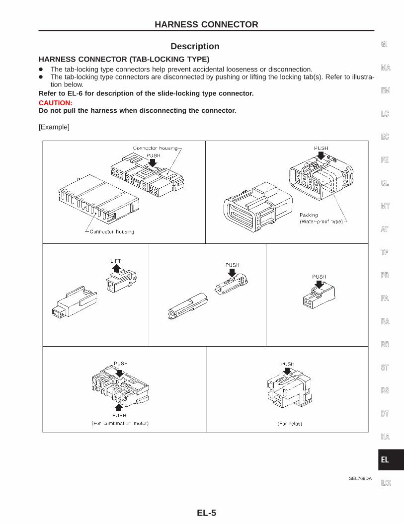
DescriptionHARNESS CONNECTOR (TAB-LOCKING TYPE)● The tab-locking type connectors help prevent accidental looseness or disconnection.● The tab-locking type connectors are disconnected by pushing or lifting the locking tab(s). Refer to illustra-
tion below.Refer to EL-6 for description of the slide-locking type connector.CAUTION:Do not pull the harness when disconnecting the connector.
[Example]
SEL769DA
GI
MA
EM
LC
EC
FE
CL
MT
AT
TF
PD
FA
RA
BR
ST
RS
BT
HA
EL
IDX
HARNESS CONNECTOR
EL-5
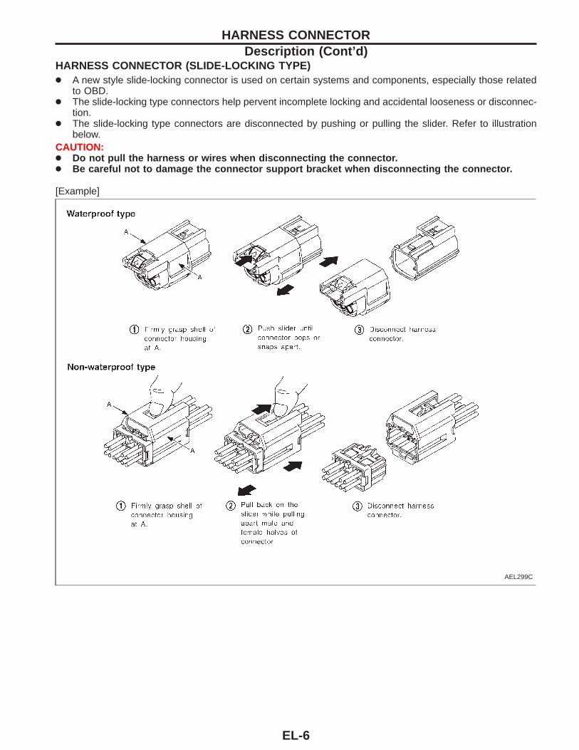
HARNESS CONNECTOR (SLIDE-LOCKING TYPE)● A new style slide-locking connector is used on certain systems and components, especially those related
to OBD.● The slide-locking type connectors help pervent incomplete locking and accidental looseness or disconnec-
tion.● The slide-locking type connectors are disconnected by pushing or pulling the slider. Refer to illustration
below.CAUTION:● Do not pull the harness or wires when disconnecting the connector.● Be careful not to damage the connector support bracket when disconnecting the connector.
[Example]
AEL299C
HARNESS CONNECTORDescription (Cont’d)
EL-6
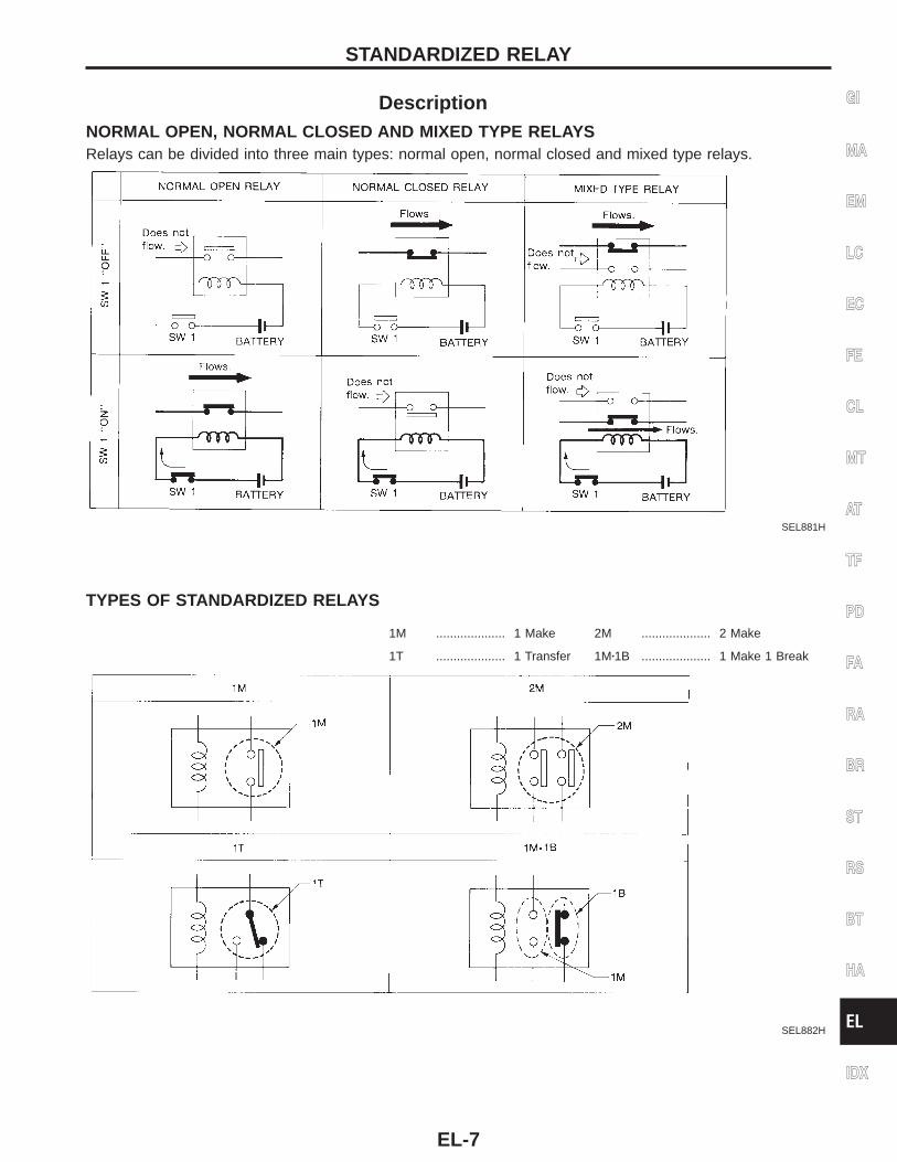
DescriptionNORMAL OPEN, NORMAL CLOSED AND MIXED TYPE RELAYSRelays can be divided into three main types: normal open, normal closed and mixed type relays.
SEL881H
TYPES OF STANDARDIZED RELAYS
1M .................... 1 Make 2M .................... 2 Make
1T .................... 1 Transfer 1Mz1B .................... 1 Make 1 Break
SEL882H
GI
MA
EM
LC
EC
FE
CL
MT
AT
TF
PD
FA
RA
BR
ST
RS
BT
HA
EL
IDX
STANDARDIZED RELAY
EL-7
AEL672B
STANDARDIZED RELAYDescription (Cont’d)
EL-8
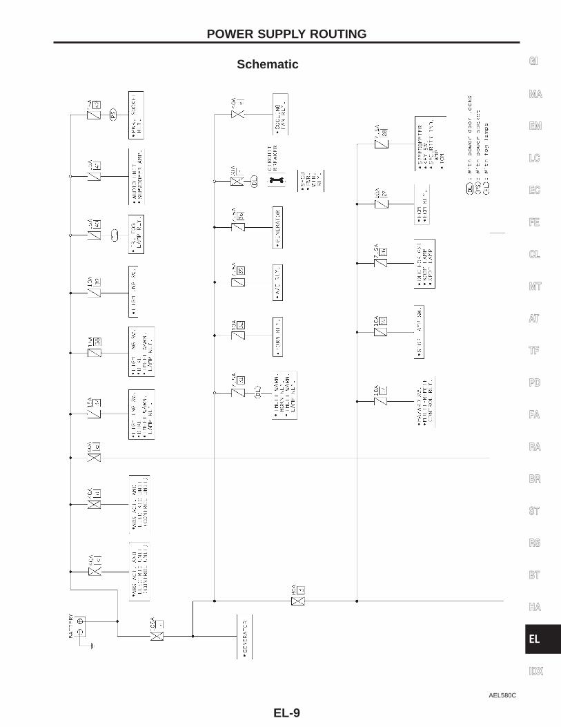
Schematic
AEL580C
GI
MA
EM
LC
EC
FE
CL
MT
AT
TF
PD
FA
RA
BR
ST
RS
BT
HA
EL
IDX
POWER SUPPLY ROUTING
EL-9
AEL581C
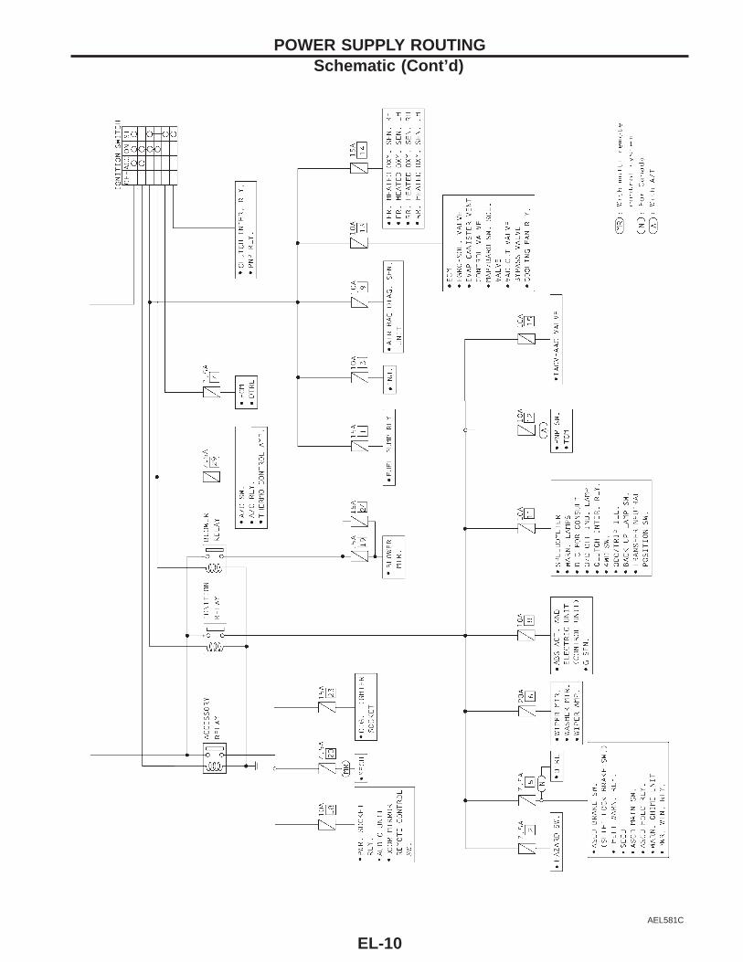
POWER SUPPLY ROUTINGSchematic (Cont’d)
EL-10
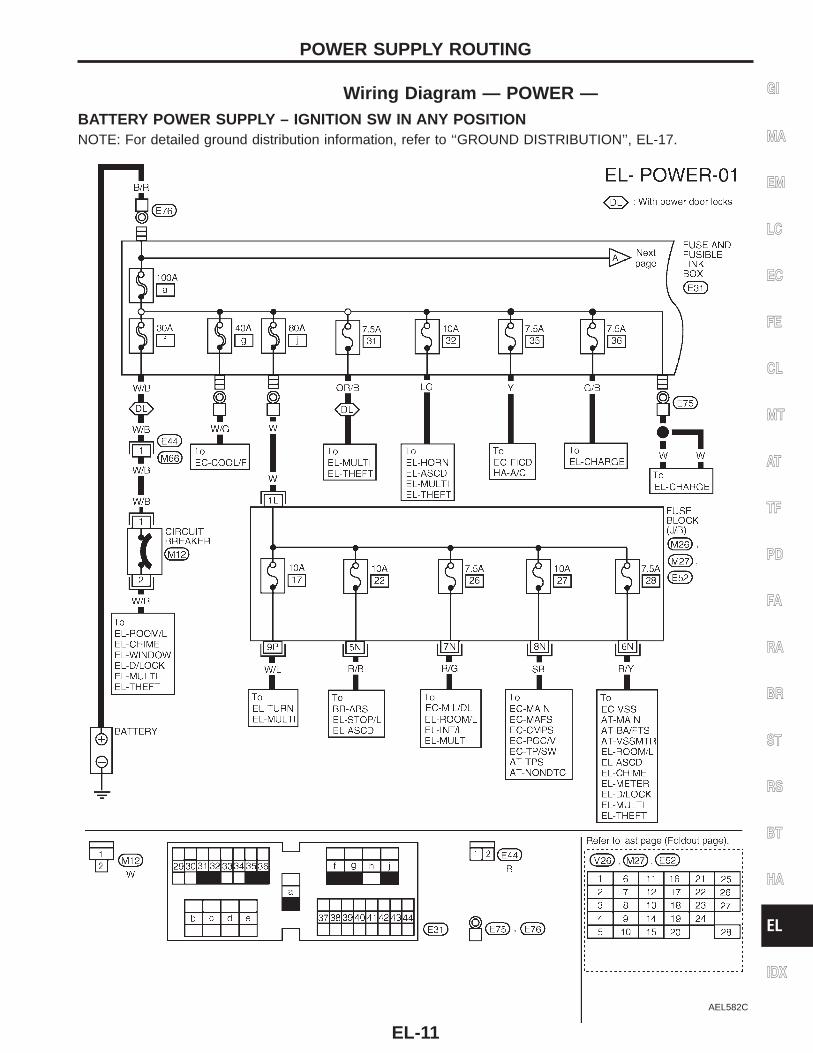
Wiring Diagram — POWER —BATTERY POWER SUPPLY – IGNITION SW IN ANY POSITIONNOTE: For detailed ground distribution information, refer to ‘‘GROUND DISTRIBUTION’’, EL-17.
AEL582C
GI
MA
EM
LC
EC
FE
CL
MT
AT
TF
PD
FA
RA
BR
ST
RS
BT
HA
EL
IDX
POWER SUPPLY ROUTING
EL-11
AEL264C
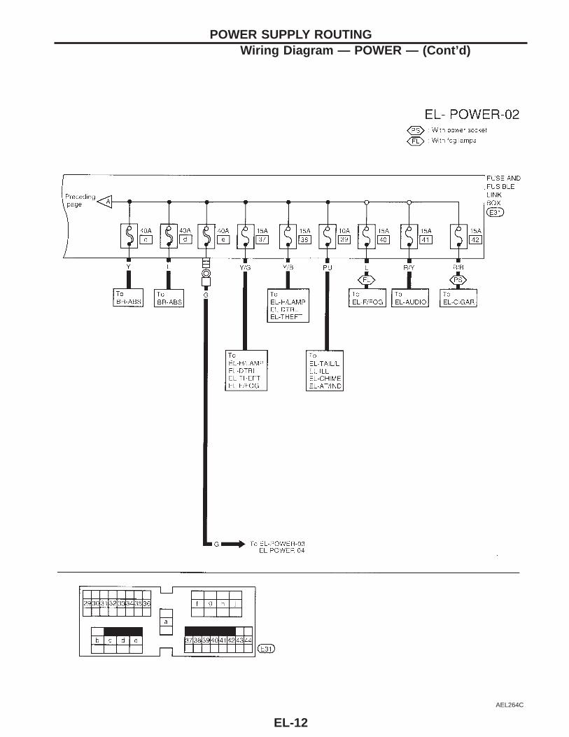
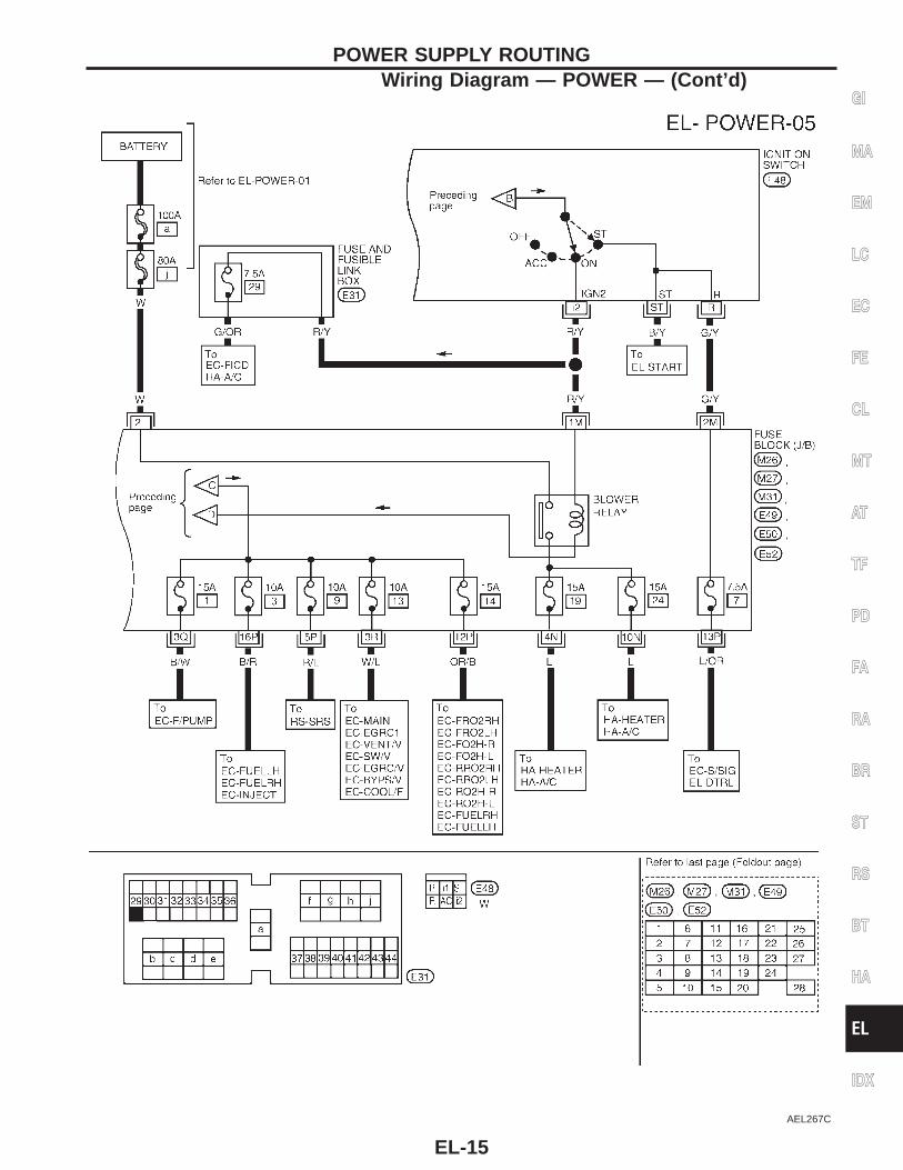
POWER SUPPLY ROUTINGWiring Diagram — POWER — (Cont’d)
EL-12
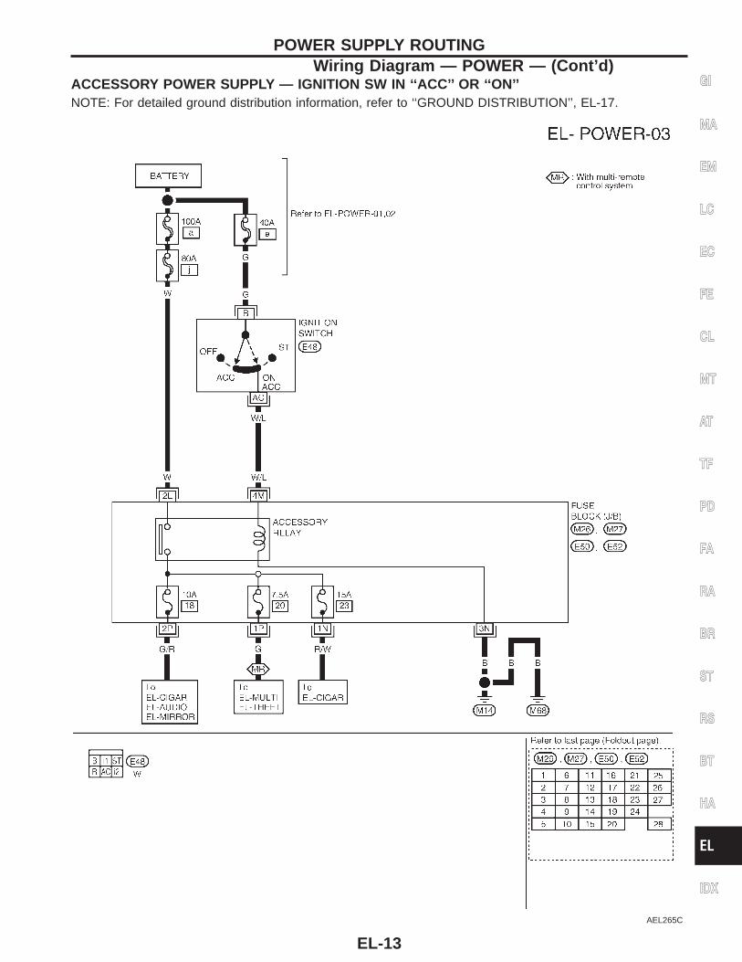
ACCESSORY POWER SUPPLY — IGNITION SW IN ‘‘ACC’’ OR ‘‘ON’’NOTE: For detailed ground distribution information, refer to ‘‘GROUND DISTRIBUTION’’, EL-17.
AEL265C
GI
MA
EM
LC
EC
FE
CL
MT
AT
TF
PD
FA
RA
BR
ST
RS
BT
HA
EL
IDX
POWER SUPPLY ROUTINGWiring Diagram — POWER — (Cont’d)
EL-13
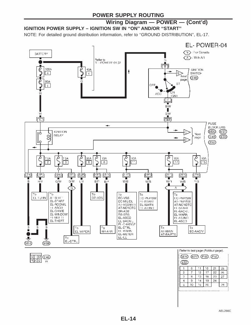
IGNITION POWER SUPPLY – IGNITION SW IN ‘‘ON’’ AND/OR ‘‘START’’NOTE: For detailed ground distribution information, refer to ‘‘GROUND DISTRIBUTION’’, EL-17.
AEL266C
POWER SUPPLY ROUTINGWiring Diagram — POWER — (Cont’d)
EL-14
AEL267C
GI
MA
EM
LC
EC
FE
CL
MT
AT
TF
PD
FA
RA
BR
ST
RS
BT
HA
EL
IDX
POWER SUPPLY ROUTINGWiring Diagram — POWER — (Cont’d)
EL-15
SEL954J
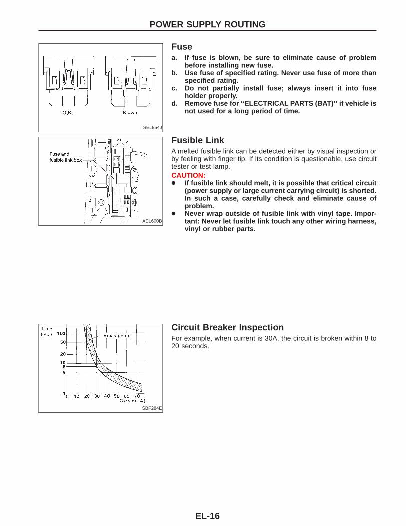
Fusea. If fuse is blown, be sure to eliminate cause of problem
before installing new fuse.b. Use fuse of specified rating. Never use fuse of more than
specified rating.c. Do not partially install fuse; always insert it into fuse
holder properly.d. Remove fuse for ‘‘ELECTRICAL PARTS (BAT)’’ if vehicle is
not used for a long period of time.
AEL600B
Fusible LinkA melted fusible link can be detected either by visual inspection orby feeling with finger tip. If its condition is questionable, use circuittester or test lamp.CAUTION:● If fusible link should melt, it is possible that critical circuit
(power supply or large current carrying circuit) is shorted.In such a case, carefully check and eliminate cause ofproblem.
● Never wrap outside of fusible link with vinyl tape. Impor-tant: Never let fusible link touch any other wiring harness,vinyl or rubber parts.
SBF284E
Circuit Breaker InspectionFor example, when current is 30A, the circuit is broken within 8 to20 seconds.
POWER SUPPLY ROUTING
EL-16
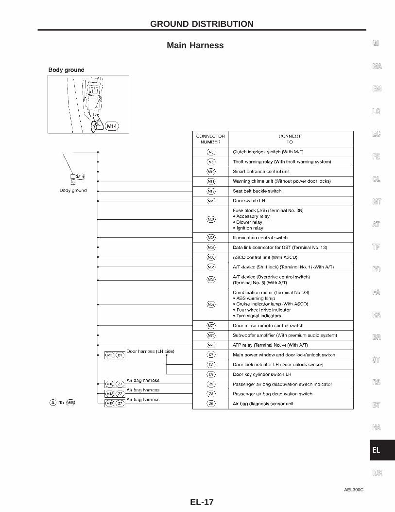
Main Harness
AEL300C
GI
MA
EM
LC
EC
FE
CL
MT
AT
TF
PD
FA
RA
BR
ST
RS
BT
HA
EL
IDX
GROUND DISTRIBUTION
EL-17
AEL301C
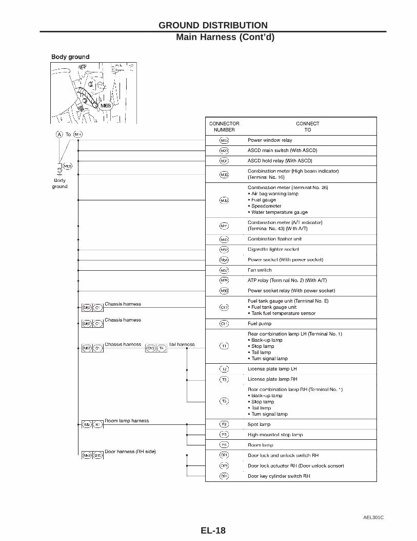
GROUND DISTRIBUTIONMain Harness (Cont’d)
EL-18
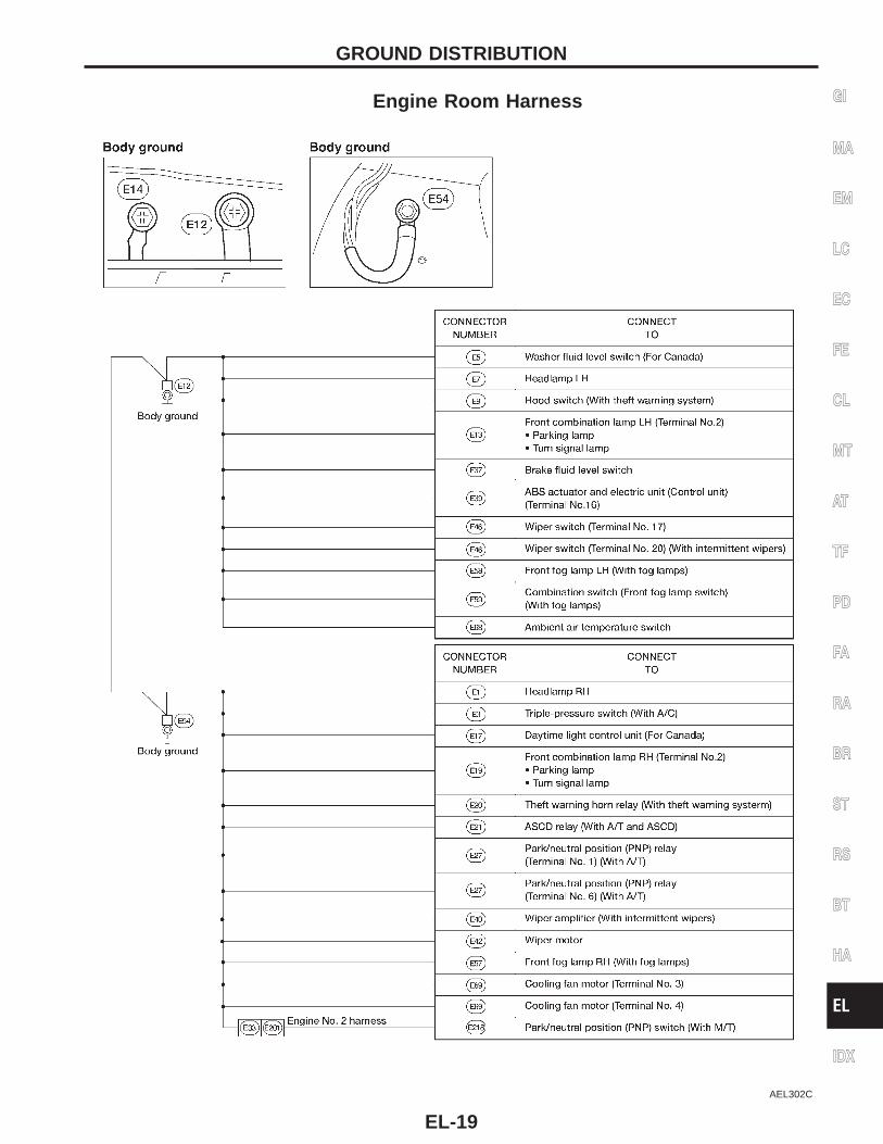
Engine Room Harness
AEL302C
GI
MA
EM
LC
EC
FE
CL
MT
AT
TF
PD
FA
RA
BR
ST
RS
BT
HA
EL
IDX
GROUND DISTRIBUTION
EL-19
AEL303C
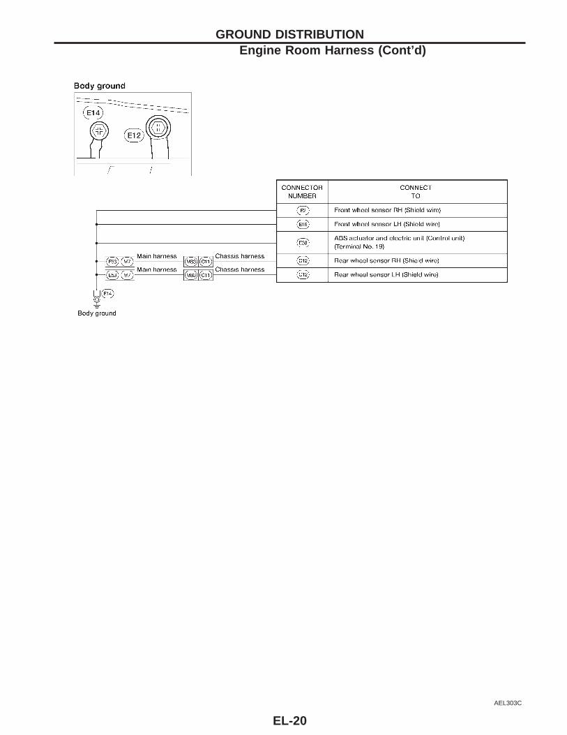
GROUND DISTRIBUTIONEngine Room Harness (Cont’d)
EL-20
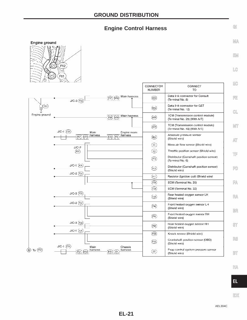
Engine Control Harness
AEL304C
GI
MA
EM
LC
EC
FE
CL
MT
AT
TF
PD
FA
RA
BR
ST
RS
BT
HA
EL
IDX
GROUND DISTRIBUTION
EL-21
AEL305C
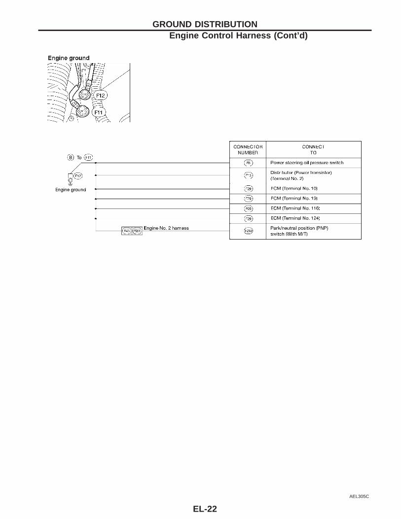
GROUND DISTRIBUTIONEngine Control Harness (Cont’d)
EL-22
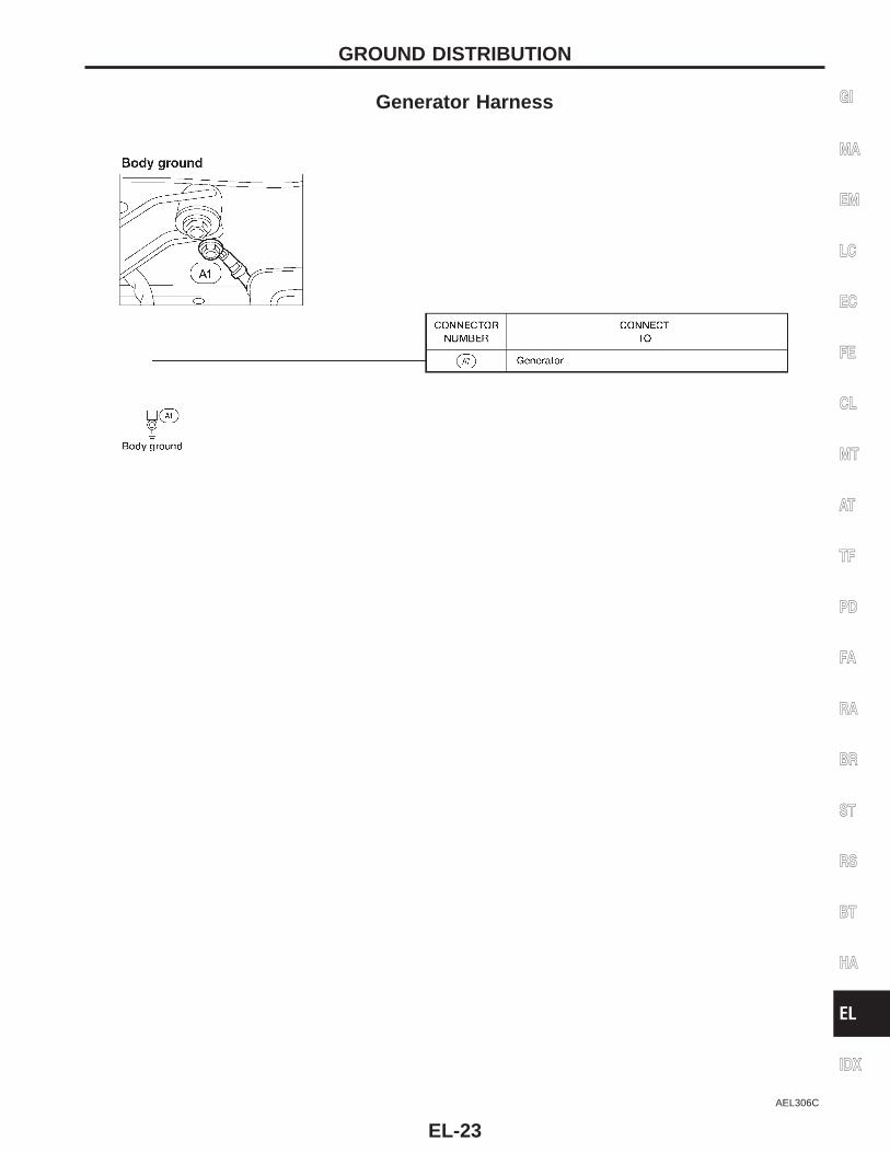
Generator Harness
AEL306C
GI
MA
EM
LC
EC
FE
CL
MT
AT
TF
PD
FA
RA
BR
ST
RS
BT
HA
EL
IDX
GROUND DISTRIBUTION
EL-23
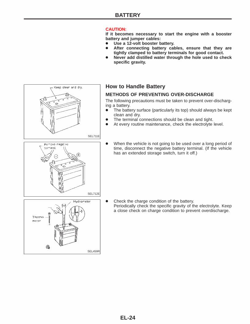
CAUTION:If it becomes necessary to start the engine with a boosterbattery and jumper cables:● Use a 12-volt booster battery.● After connecting battery cables, ensure that they are
tightly clamped to battery terminals for good contact.● Never add distilled water through the hole used to check
specific gravity.
SEL711E
How to Handle BatteryMETHODS OF PREVENTING OVER-DISCHARGEThe following precautions must be taken to prevent over-discharg-ing a battery.● The battery surface (particularly its top) should always be kept
clean and dry.● The terminal connections should be clean and tight.● At every routine maintenance, check the electrolyte level.
SEL712E
● When the vehicle is not going to be used over a long period oftime, disconnect the negative battery terminal. (If the vehiclehas an extended storage switch, turn it off.)
SEL459R
● Check the charge condition of the battery.Periodically check the specific gravity of the electrolyte. Keepa close check on charge condition to prevent overdischarge.
BATTERY
EL-24
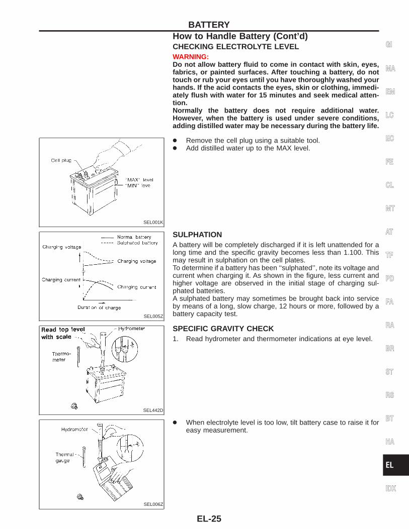
CHECKING ELECTROLYTE LEVELWARNING:Do not allow battery fluid to come in contact with skin, eyes,fabrics, or painted surfaces. After touching a battery, do nottouch or rub your eyes until you have thoroughly washed yourhands. If the acid contacts the eyes, skin or clothing, immedi-ately flush with water for 15 minutes and seek medical atten-tion.Normally the battery does not require additional water.However, when the battery is used under severe conditions,adding distilled water may be necessary during the battery life.
SEL001K
● Remove the cell plug using a suitable tool.● Add distilled water up to the MAX level.
SEL005Z
SULPHATIONA battery will be completely discharged if it is left unattended for along time and the specific gravity becomes less than 1.100. Thismay result in sulphation on the cell plates.To determine if a battery has been ‘‘sulphated’’, note its voltage andcurrent when charging it. As shown in the figure, less current andhigher voltage are observed in the initial stage of charging sul-phated batteries.A sulphated battery may sometimes be brought back into serviceby means of a long, slow charge, 12 hours or more, followed by abattery capacity test.
SEL442D
SPECIFIC GRAVITY CHECK1. Read hydrometer and thermometer indications at eye level.
SEL006Z
● When electrolyte level is too low, tilt battery case to raise it foreasy measurement.
GI
MA
EM
LC
EC
FE
CL
MT
AT
TF
PD
FA
RA
BR
ST
RS
BT
HA
EL
IDX
BATTERYHow to Handle Battery (Cont’d)
EL-25
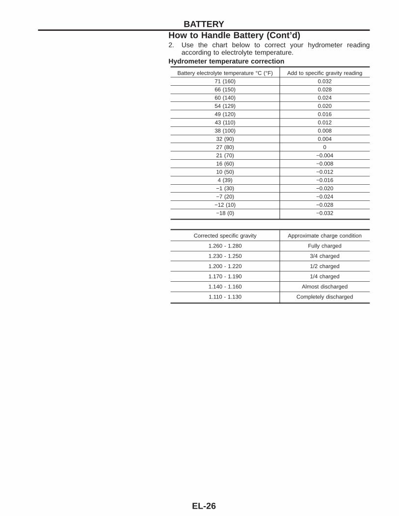
2. Use the chart below to correct your hydrometer readingaccording to electrolyte temperature.
Hydrometer temperature correction
Battery electrolyte temperature °C (°F) Add to specific gravity reading
71 (160) 0.032
66 (150) 0.028
60 (140) 0.024
54 (129) 0.020
49 (120) 0.016
43 (110) 0.012
38 (100) 0.008
32 (90) 0.004
27 (80) 0
21 (70) −0.004
16 (60) −0.008
10 (50) −0.012
4 (39) −0.016
−1 (30) −0.020
−7 (20) −0.024
−12 (10) −0.028
−18 (0) −0.032
Corrected specific gravity Approximate charge condition
1.260 - 1.280 Fully charged
1.230 - 1.250 3/4 charged
1.200 - 1.220 1/2 charged
1.170 - 1.190 1/4 charged
1.140 - 1.160 Almost discharged
1.110 - 1.130 Completely discharged
BATTERYHow to Handle Battery (Cont’d)
EL-26
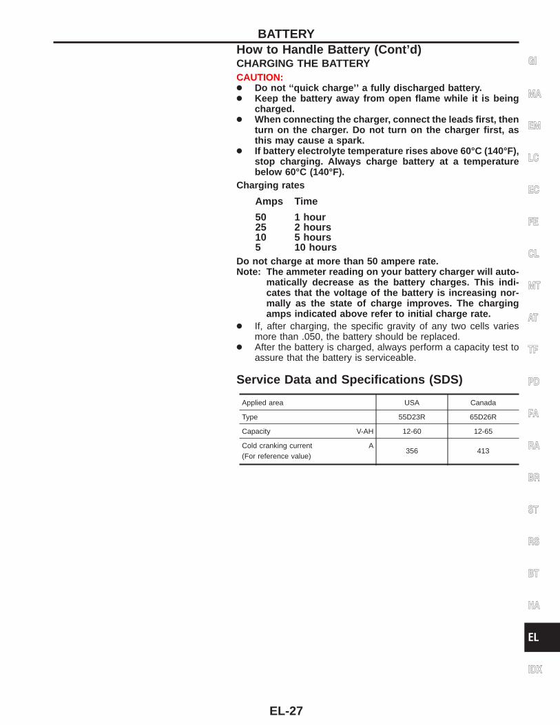
CHARGING THE BATTERYCAUTION:● Do not ‘‘quick charge’’ a fully discharged battery.● Keep the battery away from open flame while it is being
charged.● When connecting the charger, connect the leads first, then
turn on the charger. Do not turn on the charger first, asthis may cause a spark.
● If battery electrolyte temperature rises above 60°C (140°F),stop charging. Always charge battery at a temperaturebelow 60°C (140°F).
Charging rates
Amps Time
5025105
1 hour2 hours5 hours10 hours
Do not charge at more than 50 ampere rate.Note: The ammeter reading on your battery charger will auto-
matically decrease as the battery charges. This indi-cates that the voltage of the battery is increasing nor-mally as the state of charge improves. The chargingamps indicated above refer to initial charge rate.
● If, after charging, the specific gravity of any two cells variesmore than .050, the battery should be replaced.
● After the battery is charged, always perform a capacity test toassure that the battery is serviceable.
Service Data and Specifications (SDS)
Applied area USA Canada
Type 55D23R 65D26R
Capacity V-AH 12-60 12-65
Cold cranking current A(For reference value)
356 413
GI
MA
EM
LC
EC
FE
CL
MT
AT
TF
PD
FA
RA
BR
ST
RS
BT
HA
EL
IDX
BATTERYHow to Handle Battery (Cont’d)
EL-27
System DescriptionM/T MODELSPower is supplied at all times:● through 40A fusible link (letter , located in the fuse and fusible link box)● to ignition switch terminal sB .With the ignition switch in the START position, power is supplied:● through terminal sST of the ignition switch● to clutch interlock relay terminal s5 .For models with theft warning systemWith the ignition switch in the ON or START position, power is supplied:● through 7.5A fuse [No. , located in the fuse block (J/B)]● to theft warning relay terminal s2 .With the ignition switch in the ON or START position, power is supplied:● through 10A fuse [No. , located in the fuse block (J/B)]● to clutch interlock relay terminal s2 .If the theft warning system is triggered, terminal s1 of the theft warning relay is grounded through terminal s32
of the smart entrance control unit and ground to the clutch interlock relay is interrupted.When the theft warning system is not operating and clutch pedal is depressed, ground is supplied:● from clutch interlock switch terminal s2● to theft warning relay terminal s3● through theft warning relay terminal s4● to clutch interlock relay terminal s1 .For models without theft warning systemWith the ignition switch in the ON or START position, power is supplied:● through 10A fuse [No. , located in the fuse block (J/B)]● to clutch interlock relay terminal s2 .When the clutch pedal is depressed, ground is supplied:● from clutch interlock switch terminal s2● to clutch interlock relay terminal s1 .
Ground is supplied to clutch interlock switch terminal s1 through body grounds sM14 and sM68 .The clutch interlock relay is energized and power is supplied:● from terminal s3 of the clutch interlock relay● to terminal s1 of the starter motor windings.The starter motor plunger closes and provides a closed circuit between the battery and the starter motor. Thestarter motor is grounded to the engine block. With power and ground supplied, cranking occurs and the enginestarts.
STARTING SYSTEM
EL-28
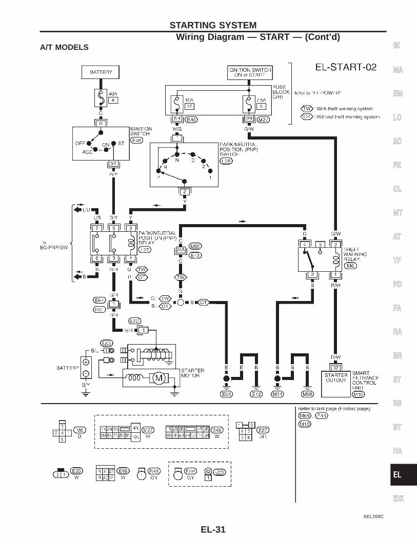
A/T MODELSPower is supplied at all times:● through 40A fusible link (letter , located in the fuse and fusible link box)● to ignition switch terminal sB .With the ignition switch in the START position, power is supplied:● through terminal sST of the ignition switch● to park/neutral position (PNP) relay terminal s5 .
For models with theft warning systemWith the ignition switch in the ON or START position, power is supplied:● through 7.5A fuse [No. , located in the fuse block (J/B)]● to theft warning relay terminal s2 .With the ignition switch in the ON or START position, power is supplied:● through 10A fuse [No. , located in the fuse block (J/B)]● to PNP switch terminal s1 .With the selector lever in the P or N position, power is supplied:● from PNP switch terminal s2● to PNP relay terminal s2 .If the theft warning system is triggered, terminal s1 of the theft warning relay is grounded through terminal s32
of the smart entrance control unit and ground to the PNP relay is interrupted.When the theft warning system is not operating, ground is supplied:● from theft warning relay terminal s3● through theft warning relay terminal s4● to PNP relay terminal s1 .
For models without theft warning systemWith the ignition switch in the ON or START position, power is supplied:● through 10A fuse [No. , located in the fuse block (J/B)]● to PNP switch terminal s1 .With the selector lever in the P or N position, power is supplied:● from PNP switch terminal s2● to PNP relay terminal s2 .
Ground is supplied to PNP relay terminal s1 through body grounds sE12 and sE54 .The PNP relay is energized and power is supplied:● from terminal s3 of the PNP relay● to terminal s1 of the starter motor windings.The starter motor plunger closes and provides a closed circuit between the battery and the starter motor. Thestarter motor is grounded to the engine block. With power and ground supplied, cranking occurs and the enginestarts.
THEFT WARNING SYSTEMThe theft warning system will interrupt ground to clutch interlock relay (M/T models) or PNP relay (A/T mod-els) if the system is triggered. The starter motor will then not crank, and the engine will not start. Refer to‘‘THEFT WARNING SYSTEM’’ (EL-189).
GI
MA
EM
LC
EC
FE
CL
MT
AT
TF
PD
FA
RA
BR
ST
RS
BT
HA
EL
IDX
STARTING SYSTEMSystem Description (Cont’d)
EL-29
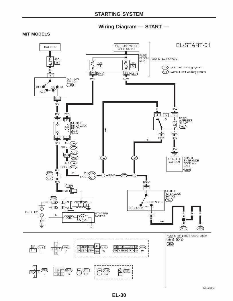
Wiring Diagram — START —M/T MODELS
AEL268C
STARTING SYSTEM
EL-30
A/T MODELS
AEL269C
GI
MA
EM
LC
EC
FE
CL
MT
AT
TF
PD
FA
RA
BR
ST
RS
BT
HA
EL
IDX
STARTING SYSTEMWiring Diagram — START — (Cont’d)
EL-31
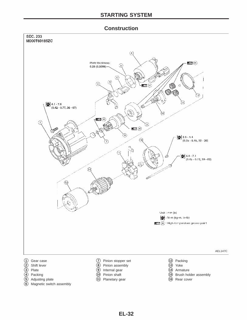
Construction
AEL147C
s1 Gear case
s2 Shift lever
s3 Plate
s4 Packing
s5 Adjusting plate
s6 Magnetic switch assembly
s7 Pinion stopper set
s8 Pinion assembly
s9 Internal gear
s10 Pinion shaft
s11 Planetary gear
s12 Packing
s13 Yoke
s14 Armature
s15 Brush holder assembly
s16 Rear cover
STARTING SYSTEM
EL-32
AEL148C
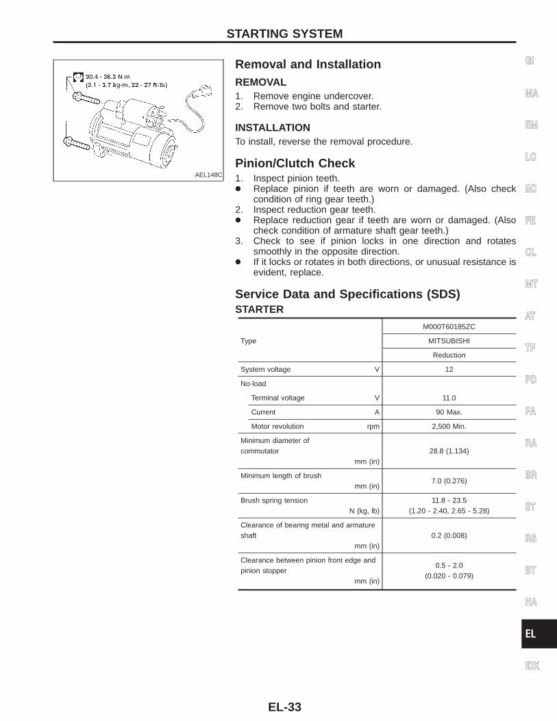
Removal and InstallationREMOVAL1. Remove engine undercover.2. Remove two bolts and starter.
INSTALLATIONTo install, reverse the removal procedure.
Pinion/Clutch Check1. Inspect pinion teeth.● Replace pinion if teeth are worn or damaged. (Also check
condition of ring gear teeth.)2. Inspect reduction gear teeth.● Replace reduction gear if teeth are worn or damaged. (Also
check condition of armature shaft gear teeth.)3. Check to see if pinion locks in one direction and rotates
smoothly in the opposite direction.● If it locks or rotates in both directions, or unusual resistance is
evident, replace.
Service Data and Specifications (SDS)STARTER
Type
M000T60185ZC
MITSUBISHI
Reduction
System voltage V 12
No-load
Terminal voltage V 11.0
Current A 90 Max.
Motor revolution rpm 2,500 Min.
Minimum diameter ofcommutator
mm (in)28.8 (1.134)
Minimum length of brushmm (in)
7.0 (0.276)
Brush spring tensionN (kg, lb)
11.8 - 23.5(1.20 - 2.40, 2.65 - 5.28)
Clearance of bearing metal and armatureshaft
mm (in)0.2 (0.008)
Clearance between pinion front edge andpinion stopper
mm (in)
0.5 - 2.0(0.020 - 0.079)
GI
MA
EM
LC
EC
FE
CL
MT
AT
TF
PD
FA
RA
BR
ST
RS
BT
HA
EL
IDX
STARTING SYSTEM
EL-33
System DescriptionThe generator provides DC voltage to operate the vehicle’s electrical system and to keep the battery charged.The voltage output is controlled by the IC regulator.Power is supplied at all times to generator terminal s4 through:● 100A fusible link (letter , located in the fuse and fusible link box), and● 7.5A fuse (No. , located in the fuse and fusible link box).Terminal s1 supplies power to charge the battery and operate the vehicle’s electrical system. Output voltageis controlled by the IC regulator at terminal s4 detecting the input voltage. The charging circuit is protected bythe 100A fusible link.Terminal s2 of the generator supplies ground through body ground sA1 .With the ignition switch in the ON or START position, power is supplied:● through 10A fuse [No. , located in the fuse block (J/B)]● to combination meter terminal s29 for the charge warning lamp.Ground is supplied to terminal s27 of the combination meter through terminal s3 of the generator. With powerand ground supplied, the charge warning lamp will illuminate. When the generator is providing sufficient volt-age with the engine running, the ground is opened and the charge warning lamp will not illuminate.If the charge warning lamp illuminates with the engine running, a fault is indicated.
CHARGING SYSTEM
EL-34
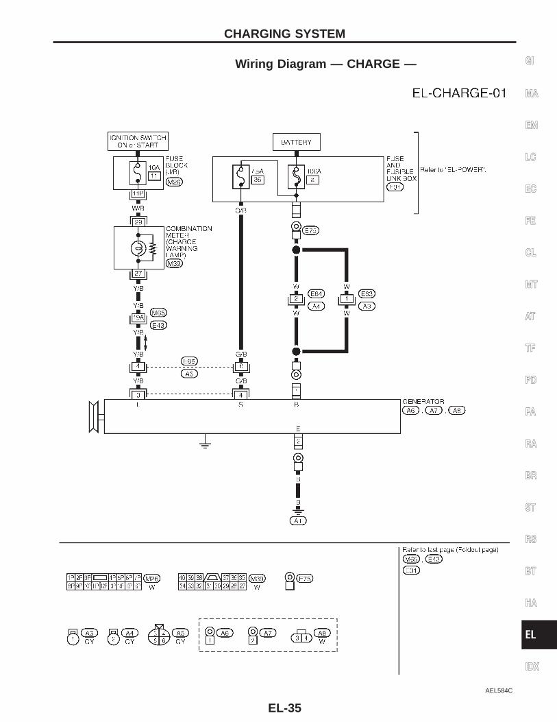
Wiring Diagram — CHARGE —
AEL584C
GI
MA
EM
LC
EC
FE
CL
MT
AT
TF
PD
FA
RA
BR
ST
RS
BT
HA
EL
IDX
CHARGING SYSTEM
EL-35
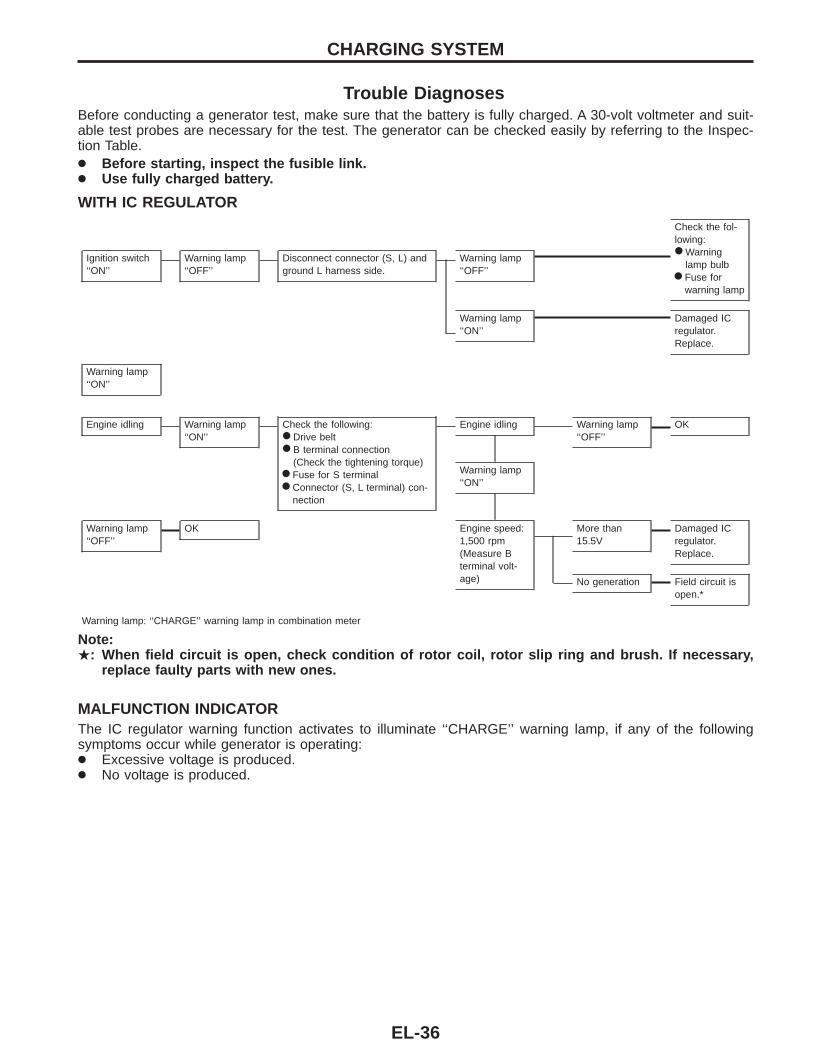
Trouble DiagnosesBefore conducting a generator test, make sure that the battery is fully charged. A 30-volt voltmeter and suit-able test probes are necessary for the test. The generator can be checked easily by referring to the Inspec-tion Table.● Before starting, inspect the fusible link.● Use fully charged battery.
WITH IC REGULATOR
Check the fol-lowing:● Warning
lamp bulb● Fuse for
warning lamp
Ignition switch‘‘ON’’
Warning lamp‘‘OFF’’
Disconnect connector (S, L) andground L harness side.
Warning lamp‘‘OFF’’
Warning lamp‘‘ON’’
Damaged ICregulator.Replace.
Warning lamp‘‘ON’’
Engine idling Warning lamp‘‘ON’’
Check the following:● Drive belt● B terminal connection
(Check the tightening torque)● Fuse for S terminal● Connector (S, L terminal) con-
nection
Engine idling Warning lamp‘‘OFF’’
OK
Warning lamp‘‘ON’’
Warning lamp‘‘OFF’’
OK Engine speed:1,500 rpm(Measure Bterminal volt-age)
More than15.5V
Damaged ICregulator.Replace.
No generation Field circuit isopen.*
Warning lamp: ‘‘CHARGE’’ warning lamp in combination meter
Note:.: When field circuit is open, check condition of rotor coil, rotor slip ring and brush. If necessary,
replace faulty parts with new ones.
MALFUNCTION INDICATORThe IC regulator warning function activates to illuminate ‘‘CHARGE’’ warning lamp, if any of the followingsymptoms occur while generator is operating:● Excessive voltage is produced.● No voltage is produced.
CHARGING SYSTEM
EL-36
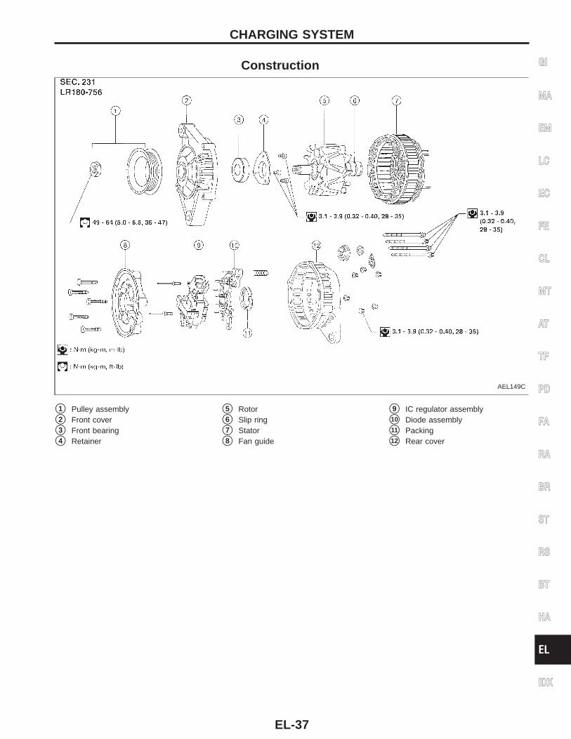
Construction
AEL149C
s1 Pulley assembly
s2 Front cover
s3 Front bearing
s4 Retainer
s5 Rotor
s6 Slip ring
s7 Stator
s8 Fan guide
s9 IC regulator assembly
s10 Diode assembly
s11 Packing
s12 Rear cover
GI
MA
EM
LC
EC
FE
CL
MT
AT
TF
PD
FA
RA
BR
ST
RS
BT
HA
EL
IDX
CHARGING SYSTEM
EL-37
AEL421C
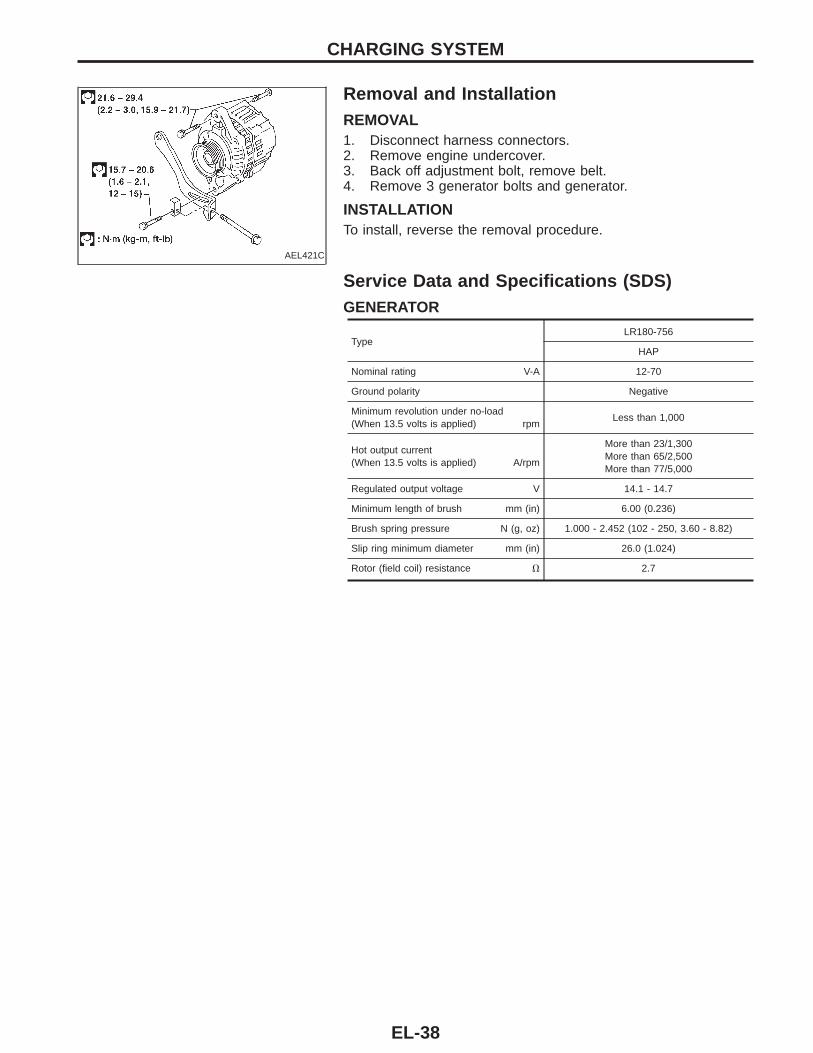
Removal and InstallationREMOVAL1. Disconnect harness connectors.2. Remove engine undercover.3. Back off adjustment bolt, remove belt.4. Remove 3 generator bolts and generator.
INSTALLATIONTo install, reverse the removal procedure.
Service Data and Specifications (SDS)GENERATOR
TypeLR180-756
HAP
Nominal rating V-A 12-70
Ground polarity Negative
Minimum revolution under no-load(When 13.5 volts is applied) rpm
Less than 1,000
Hot output current(When 13.5 volts is applied) A/rpm
More than 23/1,300More than 65/2,500More than 77/5,000
Regulated output voltage V 14.1 - 14.7
Minimum length of brush mm (in) 6.00 (0.236)
Brush spring pressure N (g, oz) 1.000 - 2.452 (102 - 250, 3.60 - 8.82)
Slip ring minimum diameter mm (in) 26.0 (1.024)
Rotor (field coil) resistance V 2.7
CHARGING SYSTEM
EL-38
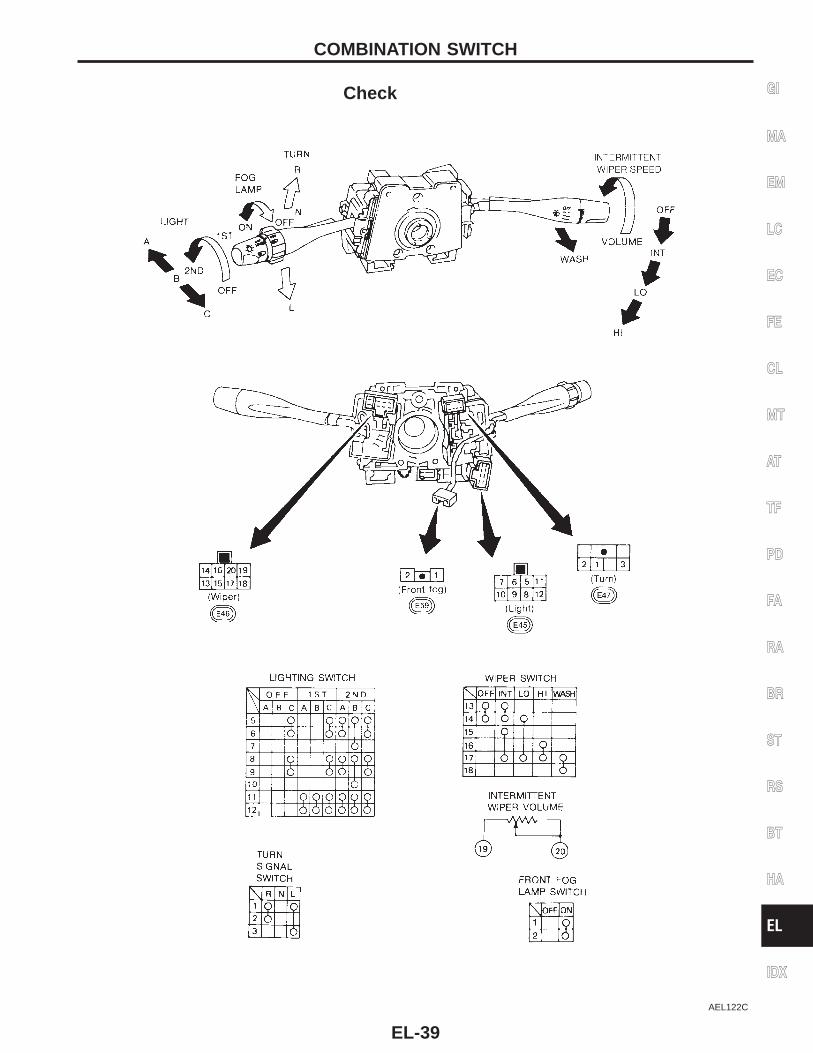
Check
AEL122C
GI
MA
EM
LC
EC
FE
CL
MT
AT
TF
PD
FA
RA
BR
ST
RS
BT
HA
EL
IDX
COMBINATION SWITCH
EL-39
SEL865L
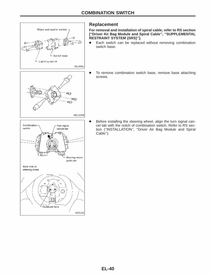
ReplacementFor removal and installation of spiral cable, refer to RS section[‘‘Driver Air Bag Module and Spiral Cable’’, ‘‘SUPPLEMENTALRESTRAINT SYSTEM (SRS)’’].● Each switch can be replaced without removing combination
switch base.
MEL205B
● To remove combination switch base, remove base attachingscrews.
ARS152
● Before installing the steering wheel, align the turn signal can-cel tab with the notch of combination switch. Refer to RS sec-tion (‘‘INSTALLATION’’, ‘‘Driver Air Bag Module and SpiralCable’’).
COMBINATION SWITCH
EL-40
Check
AEL603B
GI
MA
EM
LC
EC
FE
CL
MT
AT
TF
PD
FA
RA
BR
ST
RS
BT
HA
EL
IDX
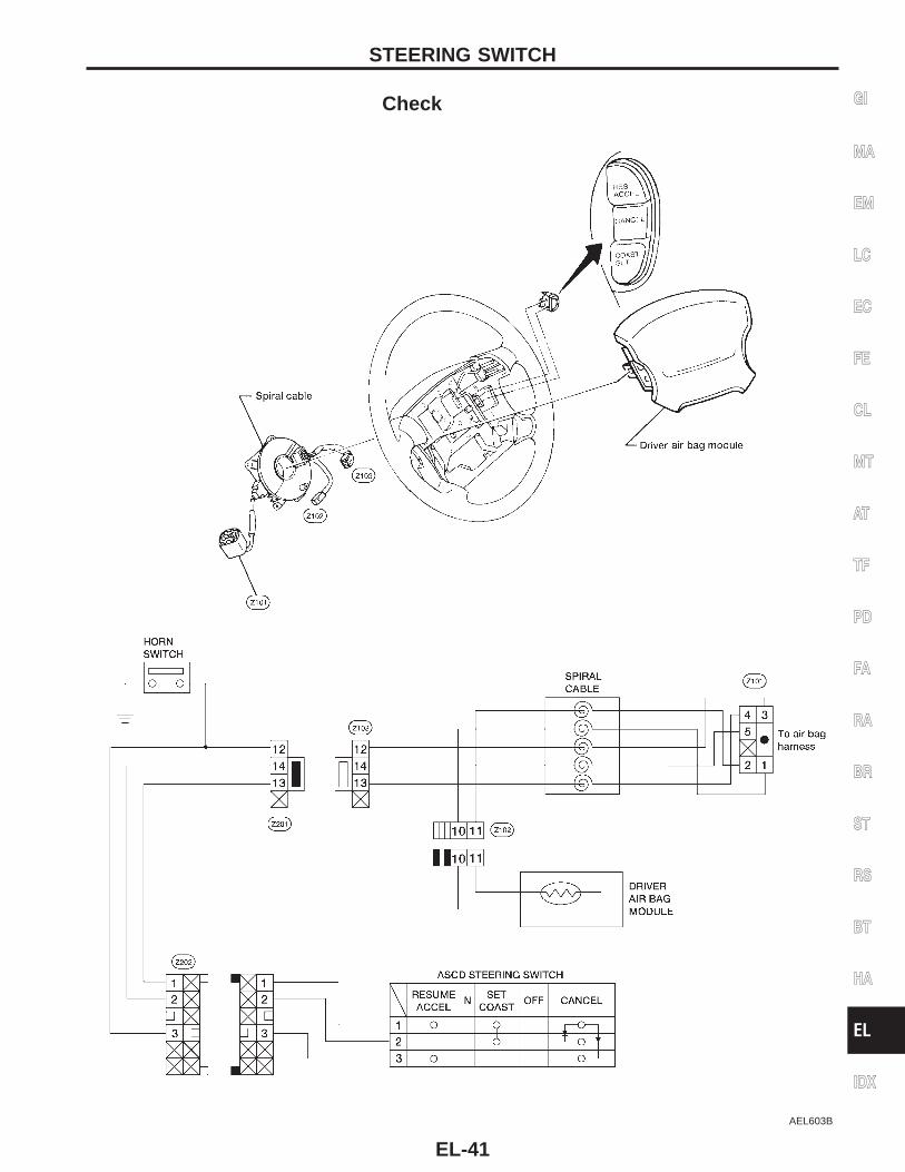
STEERING SWITCH
EL-41
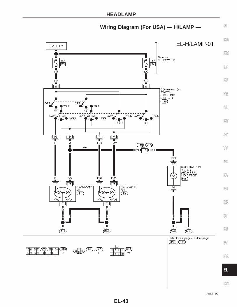
System Description (For USA)The headlamps are controlled by the lighting switch which is built into the combination switch.Power is supplied at all times:● to lighting switch terminal s5● through 15A fuse (No. , located in the fuse and fusible link box), and● to lighting switch terminal s8● through 15A fuse (No. , located in the fuse and fusible link box).Low beam operationWhen the lighting switch is turned to headlamp ON (2ND) position, LOW BEAM (B), power is supplied:● from lighting switch terminal s10
● to terminal sD of the LH headlamp, and● from lighting switch terminal s7● to terminal sD of the RH headlamp.Terminal sE of each headlamp supplies ground through body grounds sE12 and sE54 .With power and ground supplied, the headlamp(s) will illuminate.High beam operation/flash-to-pass operationWhen the lighting switch is turned to headlamp ON (2ND) position, HIGH BEAM (A) or FLASH TO PASS (C)position, power is supplied:● from lighting switch terminal s6● to terminal sM of RH headlamp, and● from lighting switch terminal s9● to terminal sM of LH headlamp, and● to combination meter terminal s17 for the high beam indicator.Ground is supplied to terminal s16 of the combination meter through body grounds sM14 and sM68 .Terminal sE of each headlamp supplies ground through body grounds sE12 and sE54 .With power and ground supplied, the high beams and the high beam indicator illuminate.Theft warning systemThe theft warning system will flash the high beams if the system is triggered. Refer to ‘‘THEFT WARNINGSYSTEM’’ (EL-189).
HEADLAMP
EL-42
Wiring Diagram (For USA) — H/LAMP —
AEL271C
GI
MA
EM
LC
EC
FE
CL
MT
AT
TF
PD
FA
RA
BR
ST
RS
BT
HA
EL
IDX
HEADLAMP
EL-43
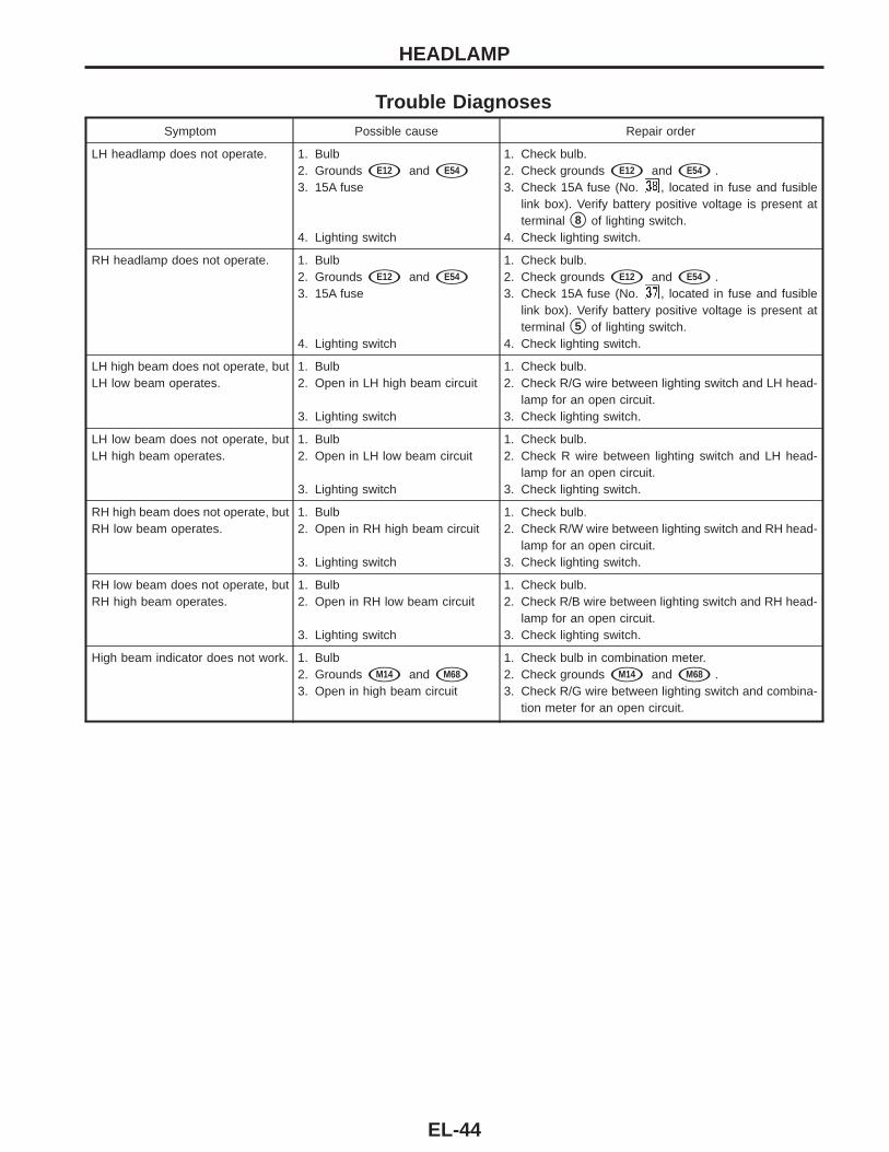
Trouble DiagnosesSymptom Possible cause Repair order
LH headlamp does not operate. 1. Bulb2. Grounds sE12 and sE54
3. 15A fuse
4. Lighting switch
1. Check bulb.2. Check grounds sE12 and sE54 .3. Check 15A fuse (No. , located in fuse and fusible
link box). Verify battery positive voltage is present atterminal s8 of lighting switch.
4. Check lighting switch.
RH headlamp does not operate. 1. Bulb2. Grounds sE12 and sE54
3. 15A fuse
4. Lighting switch
1. Check bulb.2. Check grounds sE12 and sE54 .3. Check 15A fuse (No. , located in fuse and fusible
link box). Verify battery positive voltage is present atterminal s5 of lighting switch.
4. Check lighting switch.
LH high beam does not operate, butLH low beam operates.
1. Bulb2. Open in LH high beam circuit
3. Lighting switch
1. Check bulb.2. Check R/G wire between lighting switch and LH head-
lamp for an open circuit.3. Check lighting switch.
LH low beam does not operate, butLH high beam operates.
1. Bulb2. Open in LH low beam circuit
3. Lighting switch
1. Check bulb.2. Check R wire between lighting switch and LH head-
lamp for an open circuit.3. Check lighting switch.
RH high beam does not operate, butRH low beam operates.
1. Bulb2. Open in RH high beam circuit
3. Lighting switch
1. Check bulb.2. Check R/W wire between lighting switch and RH head-
lamp for an open circuit.3. Check lighting switch.
RH low beam does not operate, butRH high beam operates.
1. Bulb2. Open in RH low beam circuit
3. Lighting switch
1. Check bulb.2. Check R/B wire between lighting switch and RH head-
lamp for an open circuit.3. Check lighting switch.
High beam indicator does not work. 1. Bulb2. Grounds sM14 and sM68
3. Open in high beam circuit
1. Check bulb in combination meter.2. Check grounds sM14 and sM68 .3. Check R/G wire between lighting switch and combina-
tion meter for an open circuit.
HEADLAMP
EL-44
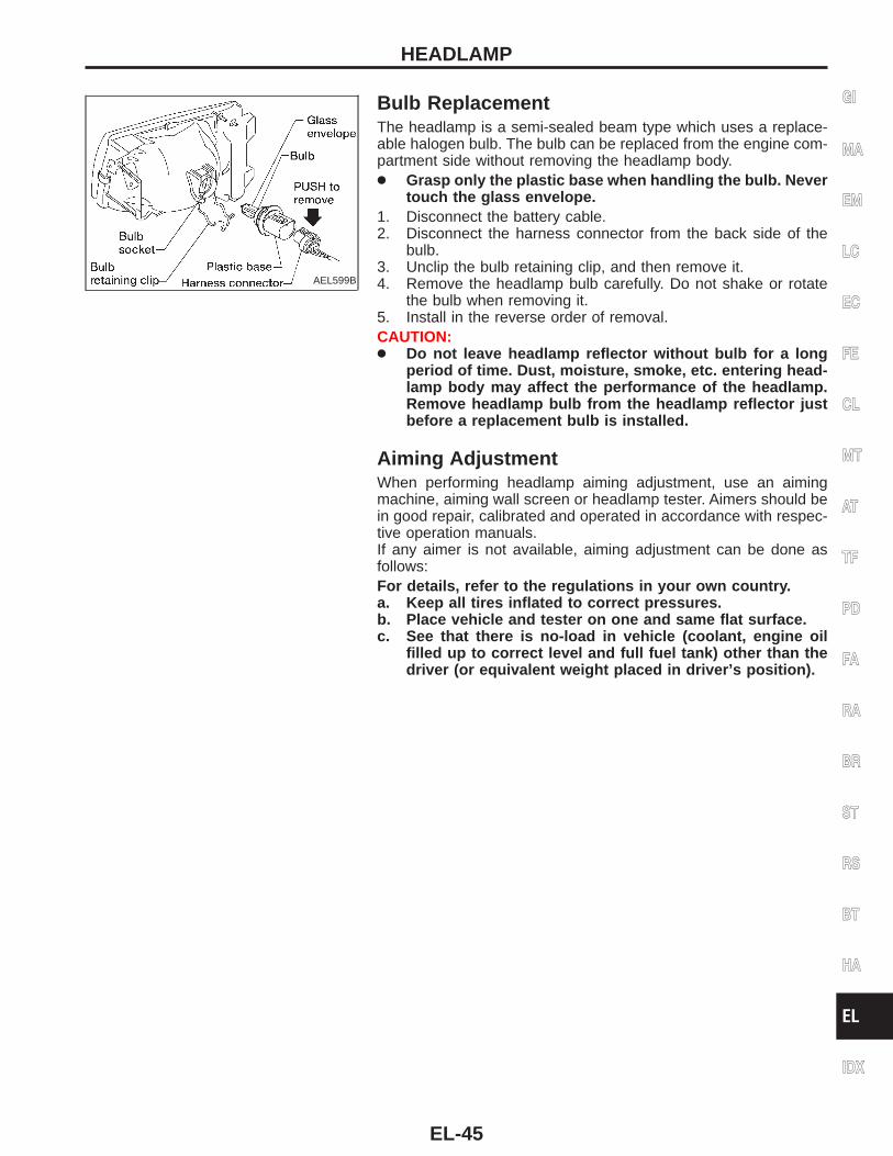
AEL599B
Bulb ReplacementThe headlamp is a semi-sealed beam type which uses a replace-able halogen bulb. The bulb can be replaced from the engine com-partment side without removing the headlamp body.● Grasp only the plastic base when handling the bulb. Never
touch the glass envelope.1. Disconnect the battery cable.2. Disconnect the harness connector from the back side of the
bulb.3. Unclip the bulb retaining clip, and then remove it.4. Remove the headlamp bulb carefully. Do not shake or rotate
the bulb when removing it.5. Install in the reverse order of removal.CAUTION:● Do not leave headlamp reflector without bulb for a long
period of time. Dust, moisture, smoke, etc. entering head-lamp body may affect the performance of the headlamp.Remove headlamp bulb from the headlamp reflector justbefore a replacement bulb is installed.
Aiming AdjustmentWhen performing headlamp aiming adjustment, use an aimingmachine, aiming wall screen or headlamp tester. Aimers should bein good repair, calibrated and operated in accordance with respec-tive operation manuals.If any aimer is not available, aiming adjustment can be done asfollows:For details, refer to the regulations in your own country.a. Keep all tires inflated to correct pressures.b. Place vehicle and tester on one and same flat surface.c. See that there is no-load in vehicle (coolant, engine oil
filled up to correct level and full fuel tank) other than thedriver (or equivalent weight placed in driver’s position).
GI
MA
EM
LC
EC
FE
CL
MT
AT
TF
PD
FA
RA
BR
ST
RS
BT
HA
EL
IDX
HEADLAMP
EL-45
AEL601B
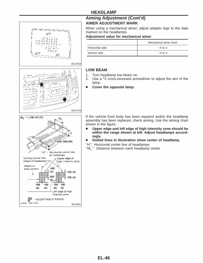
AIMER ADJUSTMENT MARKWhen using a mechanical aimer, adjust adapter legs to the datamarked on the headlamps.Adjustment value for mechanical aimer
Mechanical aimer level
Horizontal side −4 to 4
Vertical side −4 to 4
AEL671B
LOW BEAM1. Turn headlamp low beam on.2. Use a #2 cross-recessed screwdriver to adjust the aim of the
lamp.● Cover the opposite lamp.
SEL866L
If the vehicle front body has been repaired and/or the headlampassembly has been replaced, check aiming. Use the aiming chartshown in the figure.● Upper edge and left edge of high intensity zone should be
within the range shown at left. Adjust headlamps accord-ingly.
● Dotted lines in illustration show center of headlamp.‘‘H’’: Horizontal center line of headlamps‘‘WL’’: Distance between each headlamp center
HEADLAMPAiming Adjustment (Cont’d)
EL-46
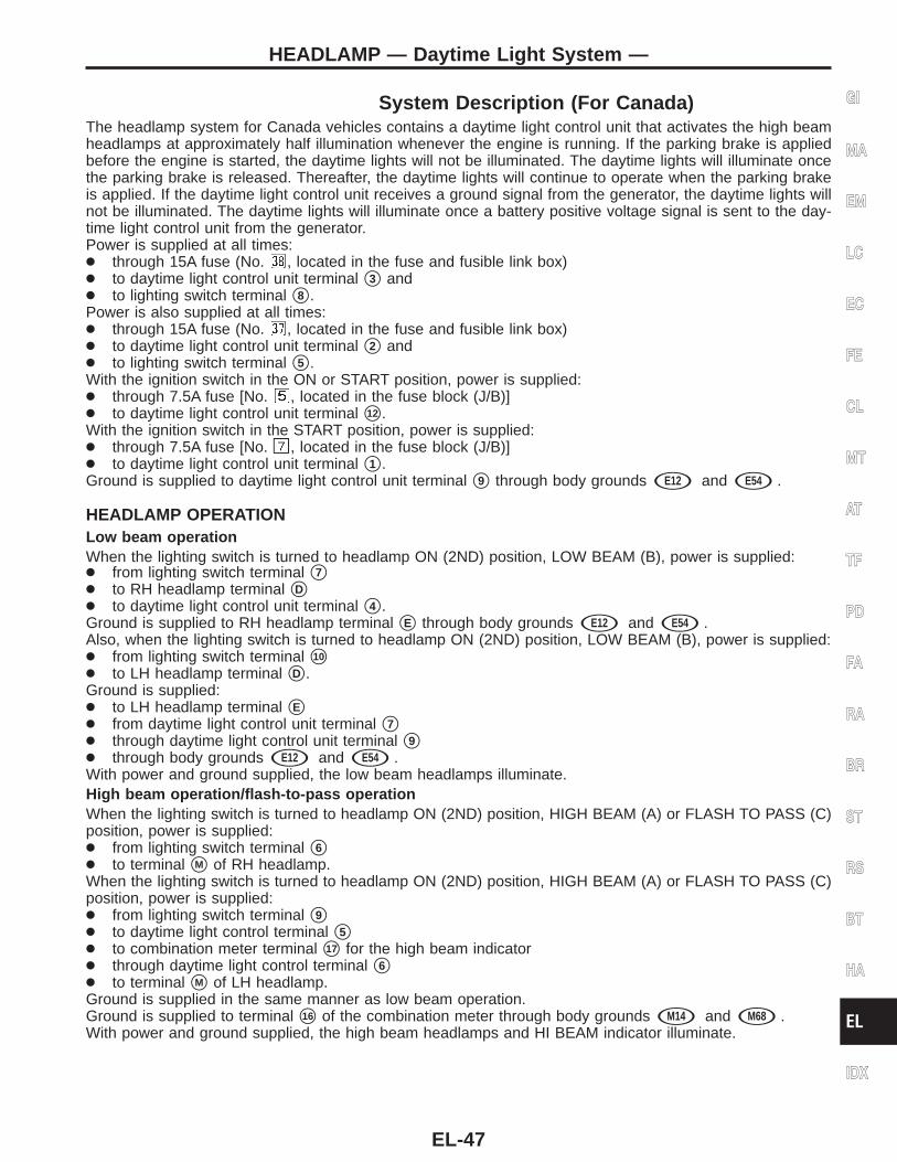
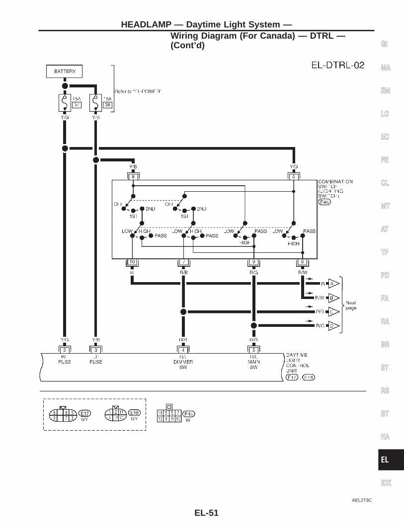
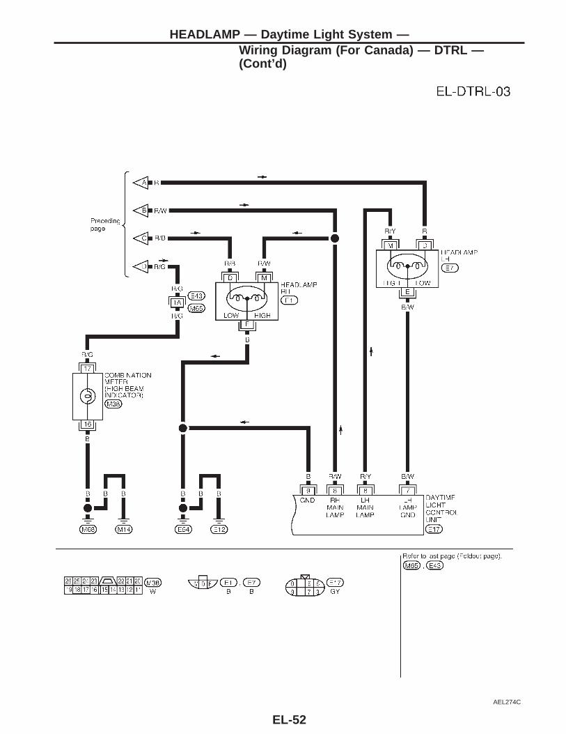
System Description (For Canada)The headlamp system for Canada vehicles contains a daytime light control unit that activates the high beamheadlamps at approximately half illumination whenever the engine is running. If the parking brake is appliedbefore the engine is started, the daytime lights will not be illuminated. The daytime lights will illuminate oncethe parking brake is released. Thereafter, the daytime lights will continue to operate when the parking brakeis applied. If the daytime light control unit receives a ground signal from the generator, the daytime lights willnot be illuminated. The daytime lights will illuminate once a battery positive voltage signal is sent to the day-time light control unit from the generator.Power is supplied at all times:● through 15A fuse (No. , located in the fuse and fusible link box)● to daytime light control unit terminal s3 and● to lighting switch terminal s8 .Power is also supplied at all times:● through 15A fuse (No. , located in the fuse and fusible link box)● to daytime light control unit terminal s2 and● to lighting switch terminal s5 .With the ignition switch in the ON or START position, power is supplied:● through 7.5A fuse [No. , located in the fuse block (J/B)]● to daytime light control unit terminal s12 .With the ignition switch in the START position, power is supplied:● through 7.5A fuse [No. , located in the fuse block (J/B)]● to daytime light control unit terminal s1 .Ground is supplied to daytime light control unit terminal s9 through body grounds sE12 and sE54 .
HEADLAMP OPERATIONLow beam operationWhen the lighting switch is turned to headlamp ON (2ND) position, LOW BEAM (B), power is supplied:● from lighting switch terminal s7● to RH headlamp terminal sD● to daytime light control unit terminal s4 .Ground is supplied to RH headlamp terminal sE through body grounds sE12 and sE54 .Also, when the lighting switch is turned to headlamp ON (2ND) position, LOW BEAM (B), power is supplied:● from lighting switch terminal s10
● to LH headlamp terminal sD .Ground is supplied:● to LH headlamp terminal sE● from daytime light control unit terminal s7● through daytime light control unit terminal s9● through body grounds sE12 and sE54 .With power and ground supplied, the low beam headlamps illuminate.High beam operation/flash-to-pass operationWhen the lighting switch is turned to headlamp ON (2ND) position, HIGH BEAM (A) or FLASH TO PASS (C)position, power is supplied:● from lighting switch terminal s6● to terminal sM of RH headlamp.When the lighting switch is turned to headlamp ON (2ND) position, HIGH BEAM (A) or FLASH TO PASS (C)position, power is supplied:● from lighting switch terminal s9● to daytime light control terminal s5● to combination meter terminal s17 for the high beam indicator● through daytime light control terminal s6● to terminal sM of LH headlamp.Ground is supplied in the same manner as low beam operation.Ground is supplied to terminal s16 of the combination meter through body grounds sM14 and sM68 .With power and ground supplied, the high beam headlamps and HI BEAM indicator illuminate.
GI
MA
EM
LC
EC
FE
CL
MT
AT
TF
PD
FA
RA
BR
ST
RS
BT
HA
EL
IDX
HEADLAMP — Daytime Light System —
EL-47
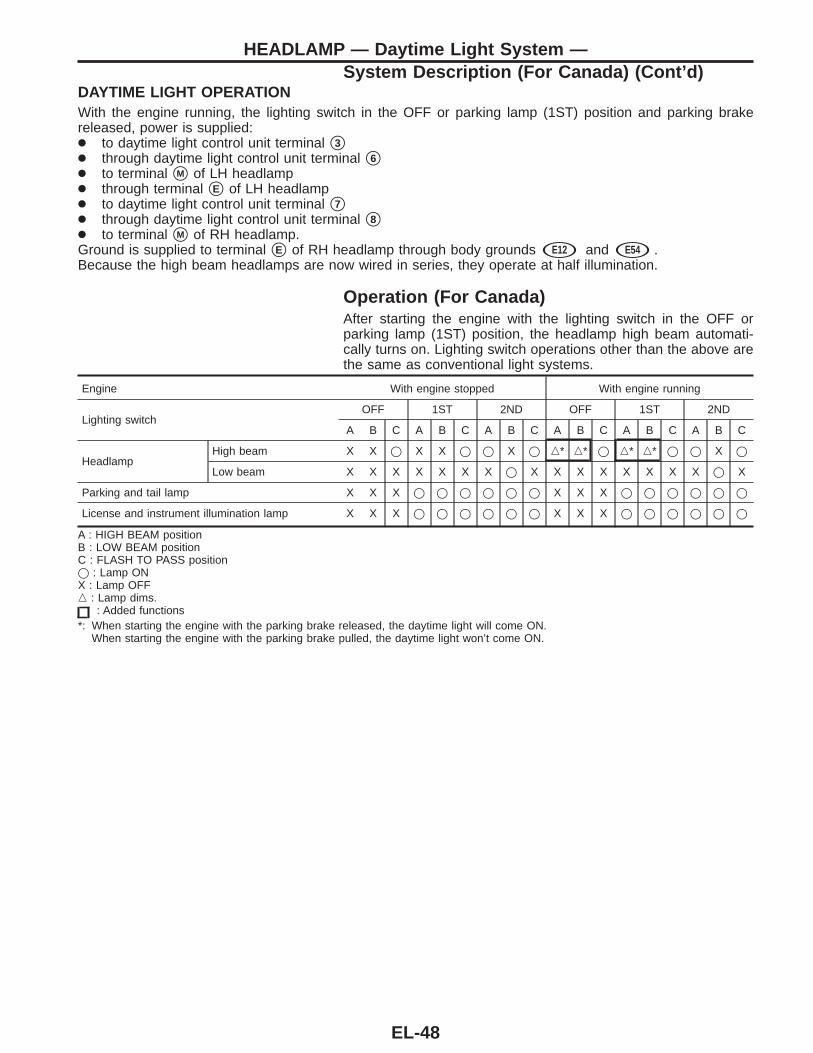
DAYTIME LIGHT OPERATIONWith the engine running, the lighting switch in the OFF or parking lamp (1ST) position and parking brakereleased, power is supplied:● to daytime light control unit terminal s3● through daytime light control unit terminal s6● to terminal sM of LH headlamp● through terminal sE of LH headlamp● to daytime light control unit terminal s7● through daytime light control unit terminal s8● to terminal sM of RH headlamp.Ground is supplied to terminal sE of RH headlamp through body grounds sE12 and sE54 .Because the high beam headlamps are now wired in series, they operate at half illumination.
Operation (For Canada)After starting the engine with the lighting switch in the OFF orparking lamp (1ST) position, the headlamp high beam automati-cally turns on. Lighting switch operations other than the above arethe same as conventional light systems.
Engine With engine stopped With engine running
Lighting switchOFF 1ST 2ND OFF 1ST 2ND
A B C A B C A B C A B C A B C A B C
HeadlampHigh beam X X j X X j j X j n* n* j n* n* j j X j
Low beam X X X X X X X j X X X X X X X X j X
Parking and tail lamp X X X j j j j j j X X X j j j j j j
License and instrument illumination lamp X X X j j j j j j X X X j j j j j j
A : HIGH BEAM positionB : LOW BEAM positionC : FLASH TO PASS positionj : Lamp ONX : Lamp OFFn : Lamp dims.
: Added functions*: When starting the engine with the parking brake released, the daytime light will come ON.
When starting the engine with the parking brake pulled, the daytime light won’t come ON.
HEADLAMP — Daytime Light System —System Description (For Canada) (Cont’d)
EL-48
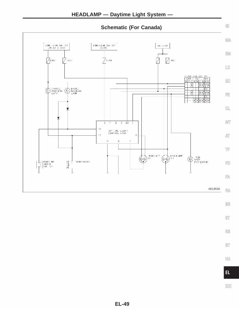
Schematic (For Canada)
AEL953A
GI
MA
EM
LC
EC
FE
CL
MT
AT
TF
PD
FA
RA
BR
ST
RS
BT
HA
EL
IDX
HEADLAMP — Daytime Light System —
EL-49
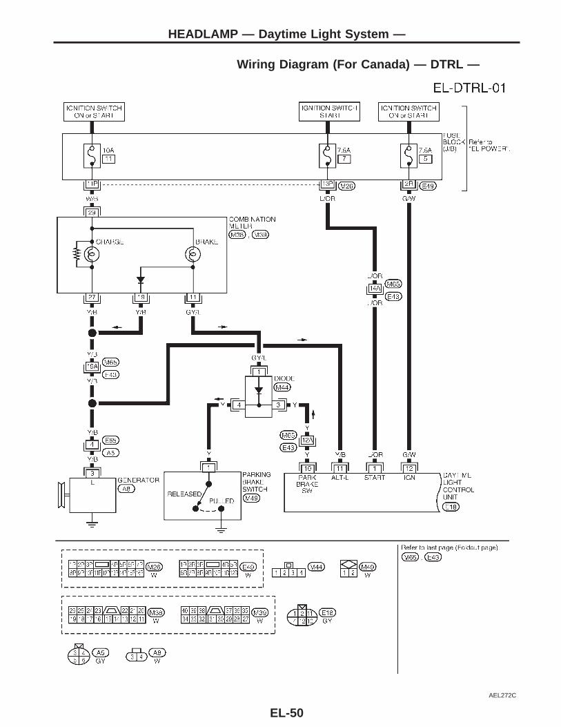
Wiring Diagram (For Canada) — DTRL —
AEL272C
HEADLAMP — Daytime Light System —
EL-50
AEL273C
GI
MA
EM
LC
EC
FE
CL
MT
AT
TF
PD
FA
RA
BR
ST
RS
BT
HA
EL
IDX
HEADLAMP — Daytime Light System —Wiring Diagram (For Canada) — DTRL —(Cont’d)
EL-51
AEL274C
HEADLAMP — Daytime Light System —Wiring Diagram (For Canada) — DTRL —(Cont’d)
EL-52
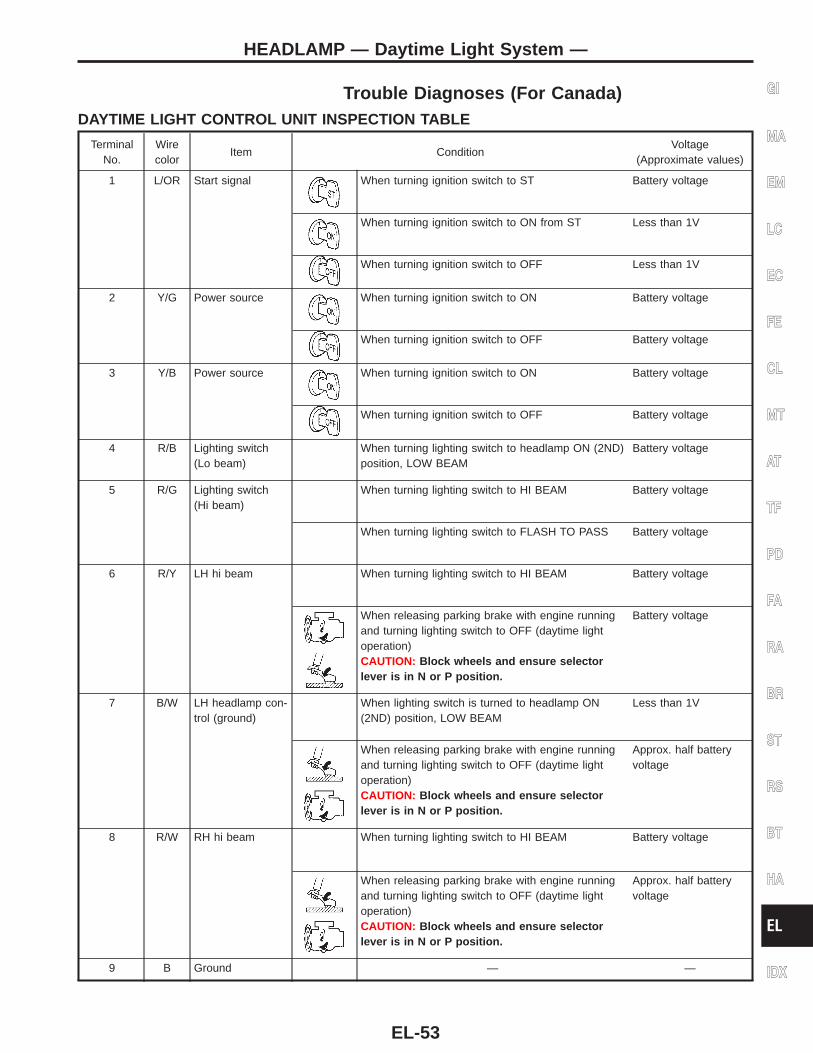
Trouble Diagnoses (For Canada)DAYTIME LIGHT CONTROL UNIT INSPECTION TABLE
TerminalNo.
Wirecolor
Item ConditionVoltage
(Approximate values)
1 L/OR Start signal When turning ignition switch to ST Battery voltage
When turning ignition switch to ON from ST Less than 1V
When turning ignition switch to OFF Less than 1V
2 Y/G Power source When turning ignition switch to ON Battery voltage
When turning ignition switch to OFF Battery voltage
3 Y/B Power source When turning ignition switch to ON Battery voltage
When turning ignition switch to OFF Battery voltage
4 R/B Lighting switch(Lo beam)
When turning lighting switch to headlamp ON (2ND)position, LOW BEAM
Battery voltage
5 R/G Lighting switch(Hi beam)
When turning lighting switch to HI BEAM Battery voltage
When turning lighting switch to FLASH TO PASS Battery voltage
6 R/Y LH hi beam When turning lighting switch to HI BEAM Battery voltage
When releasing parking brake with engine runningand turning lighting switch to OFF (daytime lightoperation)CAUTION: Block wheels and ensure selectorlever is in N or P position.
Battery voltage
7 B/W LH headlamp con-trol (ground)
When lighting switch is turned to headlamp ON(2ND) position, LOW BEAM
Less than 1V
When releasing parking brake with engine runningand turning lighting switch to OFF (daytime lightoperation)CAUTION: Block wheels and ensure selectorlever is in N or P position.
Approx. half batteryvoltage
8 R/W RH hi beam When turning lighting switch to HI BEAM Battery voltage
When releasing parking brake with engine runningand turning lighting switch to OFF (daytime lightoperation)CAUTION: Block wheels and ensure selectorlever is in N or P position.
Approx. half batteryvoltage
9 B Ground — —
GI
MA
EM
LC
EC
FE
CL
MT
AT
TF
PD
FA
RA
BR
ST
RS
BT
HA
EL
IDX
HEADLAMP — Daytime Light System —
EL-53
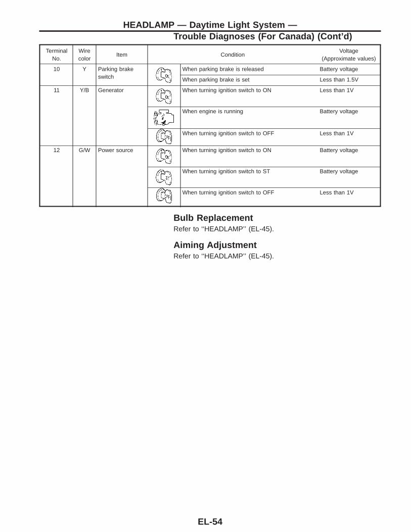
TerminalNo.
Wirecolor
Item ConditionVoltage
(Approximate values)
10 Y Parking brakeswitch
When parking brake is released Battery voltage
When parking brake is set Less than 1.5V
11 Y/B Generator When turning ignition switch to ON Less than 1V
When engine is running Battery voltage
When turning ignition switch to OFF Less than 1V
12 G/W Power source When turning ignition switch to ON Battery voltage
When turning ignition switch to ST Battery voltage
When turning ignition switch to OFF Less than 1V
Bulb ReplacementRefer to ‘‘HEADLAMP’’ (EL-45).
Aiming AdjustmentRefer to ‘‘HEADLAMP’’ (EL-45).
HEADLAMP — Daytime Light System —Trouble Diagnoses (For Canada) (Cont’d)
EL-54
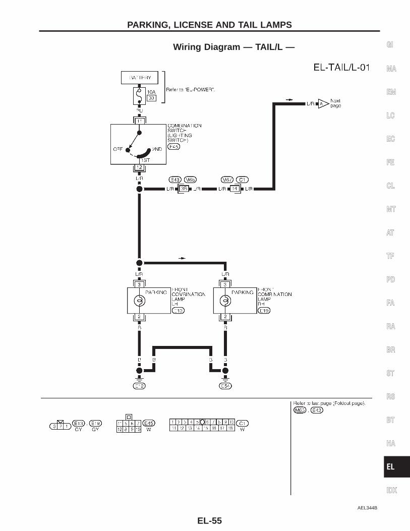
Wiring Diagram — TAIL/L —
AEL344B
GI
MA
EM
LC
EC
FE
CL
MT
AT
TF
PD
FA
RA
BR
ST
RS
BT
HA
EL
IDX
PARKING, LICENSE AND TAIL LAMPS
EL-55

Wiring Diagram — TAIL/L — (Cont’d)
AEL275C
PARKING, LICENSE AND TAIL LAMPS
EL-56
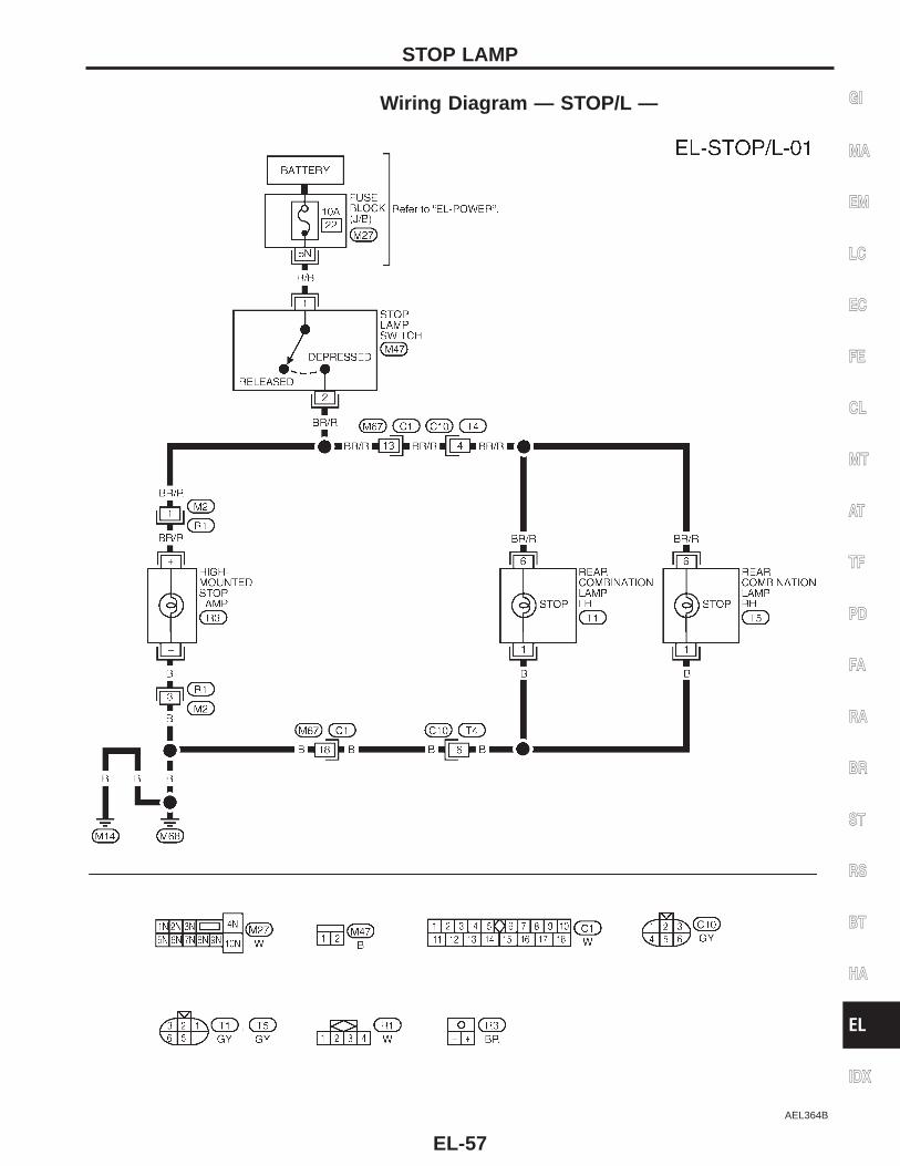
Wiring Diagram — STOP/L —
AEL364B
GI
MA
EM
LC
EC
FE
CL
MT
AT
TF
PD
FA
RA
BR
ST
RS
BT
HA
EL
IDX
STOP LAMP
EL-57
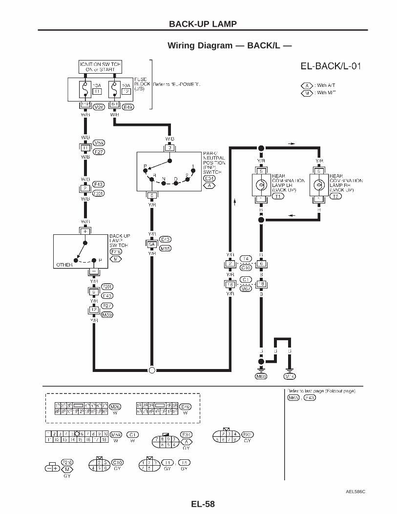
Wiring Diagram — BACK/L —
AEL586C
BACK-UP LAMP
EL-58
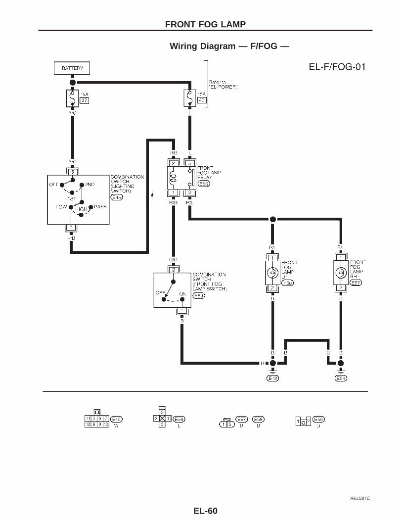
System DescriptionPower is supplied at all times to front fog lamp relay terminal s5 through:● 15A fuse (No. , located in the fuse and fusible link box).With the lighting switch in headlamp ON (2ND) position, LOW BEAM (B), power is supplied:● through 15A fuse (No. , located in the fuse and fusible link box)● to lighting switch terminal s5● through terminal s7 of the lighting switch● to front fog lamp relay terminal s2 .Fog lamp operationThe fog lamp switch is built into the combination switch. The lighting switch must be in headlamp ON (2ND)position, LOW BEAM (B) for fog lamp operation.With the front fog lamp switch in the ON position:● ground is supplied to front fog lamp relay terminal s1 through the front fog lamp switch and body grounds
sE12 and sE54 .The fog lamp relay is energized and power is supplied:● from front fog lamp relay terminal s3● to terminal s1 of each front fog lamp.Ground is supplied to terminal s2 of each front fog lamp through body grounds sE12 and sE54 .With power and ground supplied, the front fog lamps illuminate.
GI
MA
EM
LC
EC
FE
CL
MT
AT
TF
PD
FA
RA
BR
ST
RS
BT
HA
EL
IDX
FRONT FOG LAMP
EL-59
Wiring Diagram — F/FOG —
AEL587C
FRONT FOG LAMP
EL-60
AEL160C
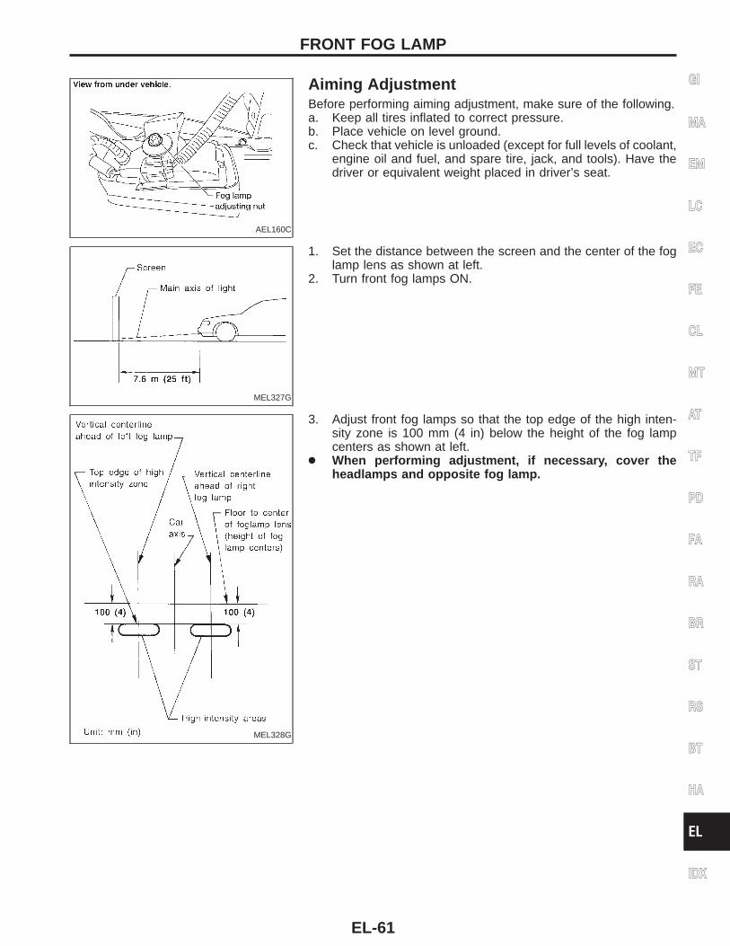
Aiming AdjustmentBefore performing aiming adjustment, make sure of the following.a. Keep all tires inflated to correct pressure.b. Place vehicle on level ground.c. Check that vehicle is unloaded (except for full levels of coolant,
engine oil and fuel, and spare tire, jack, and tools). Have thedriver or equivalent weight placed in driver’s seat.
MEL327G
1. Set the distance between the screen and the center of the foglamp lens as shown at left.
2. Turn front fog lamps ON.
MEL328G
3. Adjust front fog lamps so that the top edge of the high inten-sity zone is 100 mm (4 in) below the height of the fog lampcenters as shown at left.
● When performing adjustment, if necessary, cover theheadlamps and opposite fog lamp.
GI
MA
EM
LC
EC
FE
CL
MT
AT
TF
PD
FA
RA
BR
ST
RS
BT
HA
EL
IDX
FRONT FOG LAMP
EL-61
Removal and Installation
AEL338C
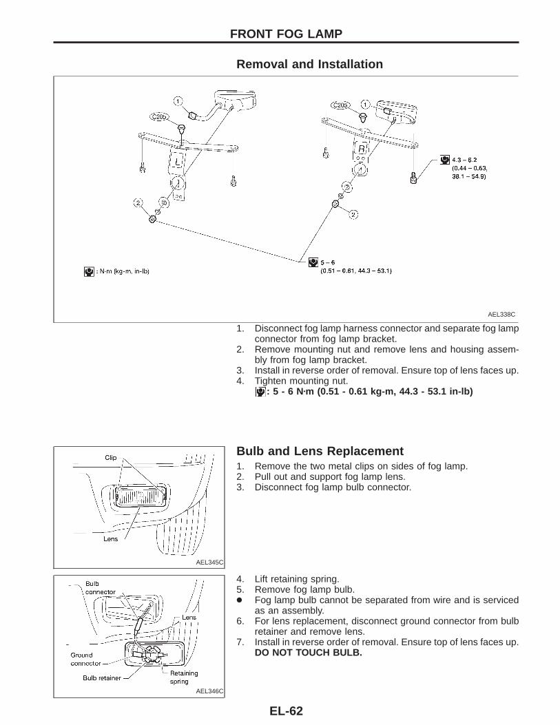
1. Disconnect fog lamp harness connector and separate fog lampconnector from fog lamp bracket.
2. Remove mounting nut and remove lens and housing assem-bly from fog lamp bracket.
3. Install in reverse order of removal. Ensure top of lens faces up.4. Tighten mounting nut.
: 5 - 6 Nzm (0.51 - 0.61 kg-m, 44.3 - 53.1 in-lb)
AEL345C
Bulb and Lens Replacement1. Remove the two metal clips on sides of fog lamp.2. Pull out and support fog lamp lens.3. Disconnect fog lamp bulb connector.
AEL346C
4. Lift retaining spring.5. Remove fog lamp bulb.● Fog lamp bulb cannot be separated from wire and is serviced
as an assembly.6. For lens replacement, disconnect ground connector from bulb
retainer and remove lens.7. Install in reverse order of removal. Ensure top of lens faces up.
DO NOT TOUCH BULB.
FRONT FOG LAMP
EL-62
System DescriptionTURN SIGNAL OPERATIONWith the hazard switch in the OFF position and the ignition switch in the ON or START position, power is sup-plied:● through 7.5A fuse [No. , located in the fuse block (J/B)]● to hazard switch terminal s2● through terminal s1 of the hazard switch● to combination flasher unit terminal sB● through terminal sL of the combination flasher unit● to turn signal switch terminal s1 .Ground is supplied to combination flasher unit terminal sE through body grounds sM14 and sM68 .LH turnWhen the turn signal switch is moved to the LH position, power is supplied from turn signal switch terminal s3
to:● front combination lamp LH terminal s1● combination meter terminal s24
● rear combination lamp LH terminal s2 .Ground is supplied to the front combination lamp LH terminal s2 through body grounds sE12 and sE54 .Ground is supplied to the rear combination lamp LH terminal s1 through body grounds sM14 and sM68 .Ground is supplied to combination meter terminal s33 through body grounds sM14 and sM68 .With power and ground supplied, the combination flasher unit controls the flashing of the LH combinationlamps.RH turnWhen the turn signal switch is moved to the RH position, power is supplied from turn signal switch terminals2 to:● front combination lamp RH terminal s1● combination meter terminal s40
● rear combination lamp RH terminal s2 .Ground is supplied to the front combination lamp RH terminal s2 through body grounds sE12 and sE54 .Ground is supplied to the rear combination lamp RH terminal s1 through body grounds sM14 and sM68 .Ground is supplied to combination meter terminal s33 through body grounds sM14 and sM68 .With power and ground supplied, the combination flasher unit controls the flashing of the RH combinationlamps.
HAZARD LAMP OPERATIONPower is supplied at all times to hazard switch terminal s3 through:● 10A fuse [No. , located in the fuse block (J/B)].With the hazard switch in the ON position, power is supplied:● through terminal s1 of the hazard switch● to combination flasher unit terminal sB● through terminal sL of the combination flasher unit● to hazard switch terminal s4 .Ground is supplied to combination flasher unit terminal sE through body grounds sM14 and sM68 .Power is supplied through terminal s5 of the hazard switch to:● front combination lamp LH terminal s1● combination meter terminal s24
● rear combination lamp LH terminal s2 .Power is supplied through terminal s6 of the hazard switch to:● front combination lamp RH terminal s1● combination meter terminal s40
● rear combination lamp RH terminal s2 .Ground is supplied to terminal s2 of each front combination lamp through body grounds sE12 and sE54 .Ground is supplied to terminal s1 of each rear combination lamp through body groundssM14 andsM68 .Ground is supplied to combination meter terminal s33 through body grounds sM14 and sM68 .With power and ground supplied, the combination flasher unit controls the flashing of the hazard warninglamps.
GI
MA
EM
LC
EC
FE
CL
MT
AT
TF
PD
FA
RA
BR
ST
RS
BT
HA
EL
IDX
TURN SIGNAL AND HAZARD WARNING LAMPS
EL-63
WITH MULTI-REMOTE CONTROL SYSTEMPower is supplied at all times:● through 10A fuse [No. , located in the fuse block (J/B)]● to multi-remote control relay terminals s2 , s5 and s7 .Ground is supplied to multi-remote control relay terminal s1 , when the multi-remote control system is triggeredthrough the smart entrance control unit.Refer to ‘‘MULTI-REMOTE CONTROL SYSTEM’’ (EL-174).When multi-remote control relay is energized.Power is supplied through terminal s3 of the multi-remote control relay:● to front combinaton lamp LH terminal s1● to combination meter terminal s24
● to rear combination lamp LH terminal s2 .Power is supplied through terminal s6 of the multi-remote control relay:● to front combination lamp RH terminal s1● to combination meter terminal s40
● to rear combination lamp RH terminal s2 .Ground is supplied to terminal s2 of each front combination lamp through body grounds sE12 and sE54 .Ground is supplied to terminal s1 of each rear combination lamp through body grounds sM14 and sM68 .Ground is supplied to combination meter terminal s33 through body grounds sM14 and sM68 .With power and ground supplied, the smart entrance control unit controls the flashing of the hazard warninglamps.
TURN SIGNAL AND HAZARD WARNING LAMPSSystem Description (Cont’d)
EL-64
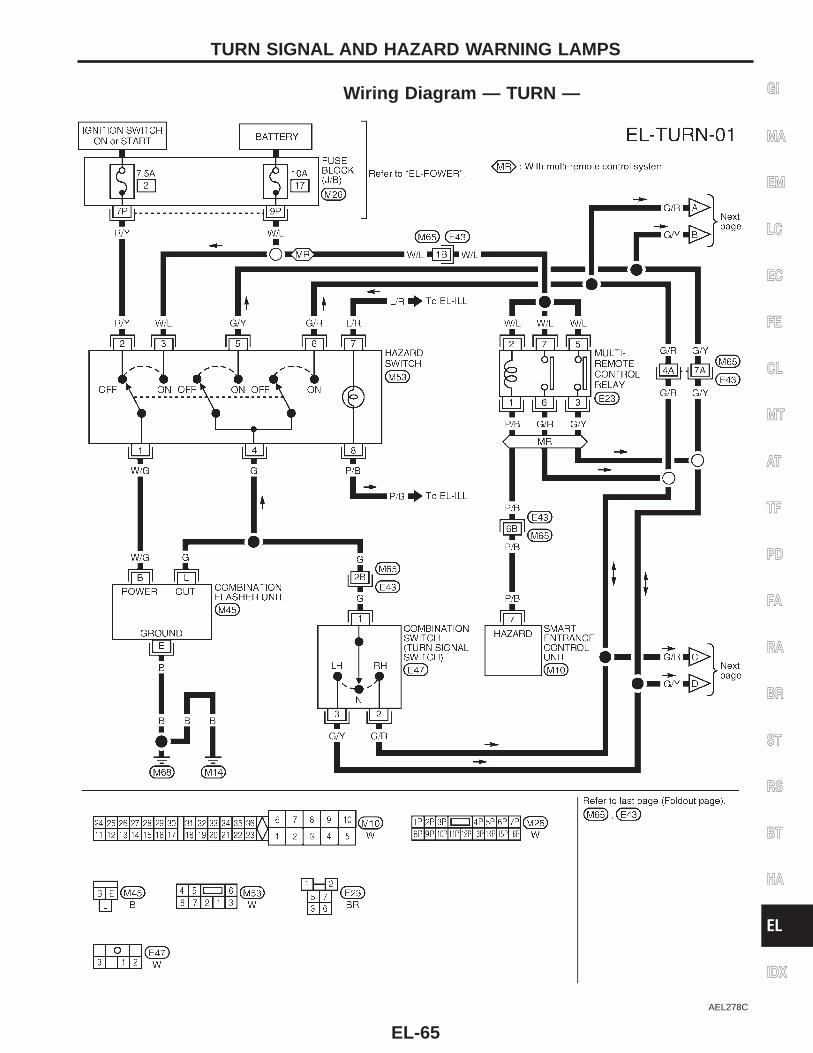
Wiring Diagram — TURN —
AEL278C
GI
MA
EM
LC
EC
FE
CL
MT
AT
TF
PD
FA
RA
BR
ST
RS
BT
HA
EL
IDX
TURN SIGNAL AND HAZARD WARNING LAMPS
EL-65
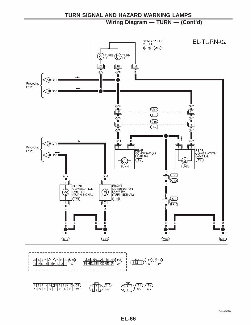
AEL279C
TURN SIGNAL AND HAZARD WARNING LAMPSWiring Diagram — TURN — (Cont’d)
EL-66
Trouble DiagnosesSymptom Possible cause Repair order
Turn signal and hazard warninglamps do not operate.
1. Hazard switch2. Combination flasher unit3. Open in combination flasher unit
circuit
1. Check hazard switch.2. Refer to combination flasher unit check.3. Check wiring to combination flasher unit for open cir-
cuit.
Turn signal lamps do not operatebut hazard warning lamps operate.
1. 7.5A fuse
2. Hazard switch3. Turn signal switch4. Open in turn signal switch circuit
1. Check 7.5A fuse [No. , located in fuse block(J/B)]. Turn ignition switch ON and verify batterypositive voltage is present at terminal s2 of hazardswitch.
2. Check hazard switch.3. Check turn signal switch.4. Check G wire between combination flasher unit and
turn signal switch for open circuit.
Hazard warning lamps do not oper-ate but turn signal lamps operate.
1. 10A fuse
2. Hazard switch3. Open in hazard switch circuit
1. Check 10A fuse [No. , located in fuse block (J/B)].Verify battery positive voltage is present at terminal
s3 of hazard switch.2. Check hazard switch.3. Check G wire between combination flasher unit and
hazard switch for open circuit.
Front turn signal lamp LH or RHdoes not operate.
1. Bulb2. Grounds sE12 and sE54
1. Check bulb.2. Check grounds sE12 and sE54 .
Rear turn signal lamp LH or RHdoes not operate.
1. Bulb2. Grounds sM14 and sM68
1. Check bulb.2. Check grounds sM14 and sM68 .
LH and RH turn indicators do notoperate.
1. Ground 1. Check grounds sM14 and sM68 .
LH or RH turn indicator does notoperate.
1. Bulb 1. Check bulb in combination meter.
SEL122E
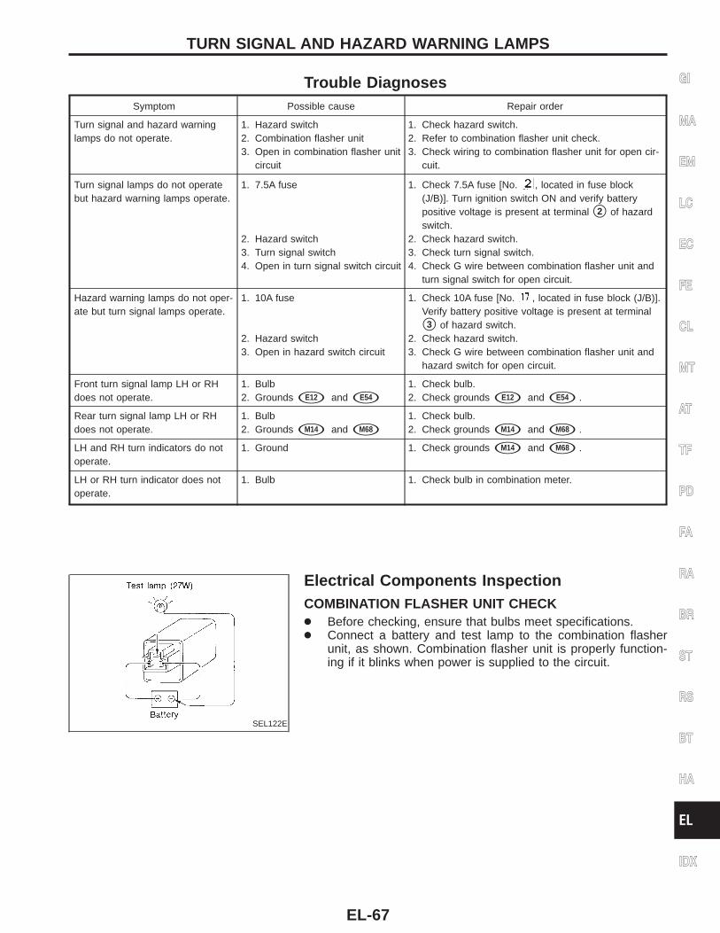
Electrical Components InspectionCOMBINATION FLASHER UNIT CHECK● Before checking, ensure that bulbs meet specifications.● Connect a battery and test lamp to the combination flasher
unit, as shown. Combination flasher unit is properly function-ing if it blinks when power is supplied to the circuit.
GI
MA
EM
LC
EC
FE
CL
MT
AT
TF
PD
FA
RA
BR
ST
RS
BT
HA
EL
IDX
TURN SIGNAL AND HAZARD WARNING LAMPS
EL-67
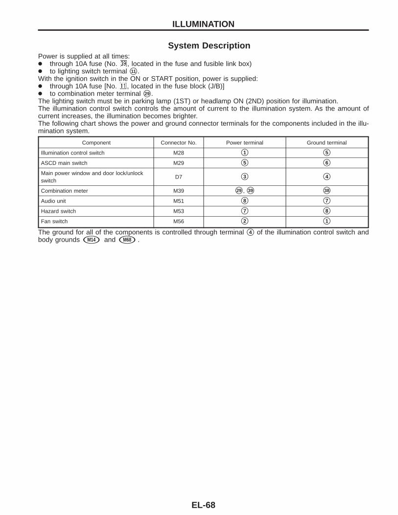
System DescriptionPower is supplied at all times:● through 10A fuse (No. , located in the fuse and fusible link box)● to lighting switch terminal s11 .With the ignition switch in the ON or START position, power is supplied:● through 10A fuse [No. , located in the fuse block (J/B)]● to combination meter terminal s29 .The lighting switch must be in parking lamp (1ST) or headlamp ON (2ND) position for illumination.The illumination control switch controls the amount of current to the illumination system. As the amount ofcurrent increases, the illumination becomes brighter.The following chart shows the power and ground connector terminals for the components included in the illu-mination system.
Component Connector No. Power terminal Ground terminal
Illumination control switch M28 s1 s5
ASCD main switch M29 s5 s6
Main power window and door lock/unlockswitch
D7 s3 s4
Combination meter M39 s29 , s39 s38
Audio unit M51 s8 s7
Hazard switch M53 s7 s8
Fan switch M56 s2 s1
The ground for all of the components is controlled through terminal s4 of the illumination control switch andbody grounds sM14 and sM68 .
ILLUMINATION
EL-68
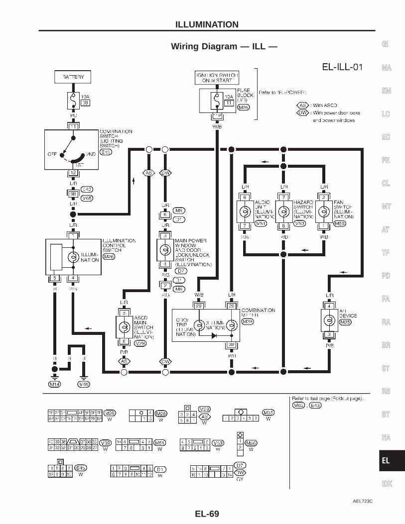
Wiring Diagram — ILL —
AEL723C
GI
MA
EM
LC
EC
FE
CL
MT
AT
TF
PD
FA
RA
BR
ST
RS
BT
HA
EL
IDX
ILLUMINATION
EL-69
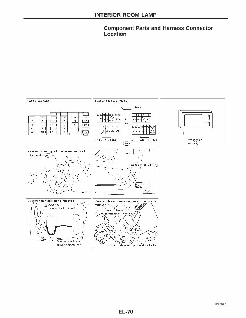
Component Parts and Harness ConnectorLocation
AEL307C
INTERIOR ROOM LAMP
EL-70
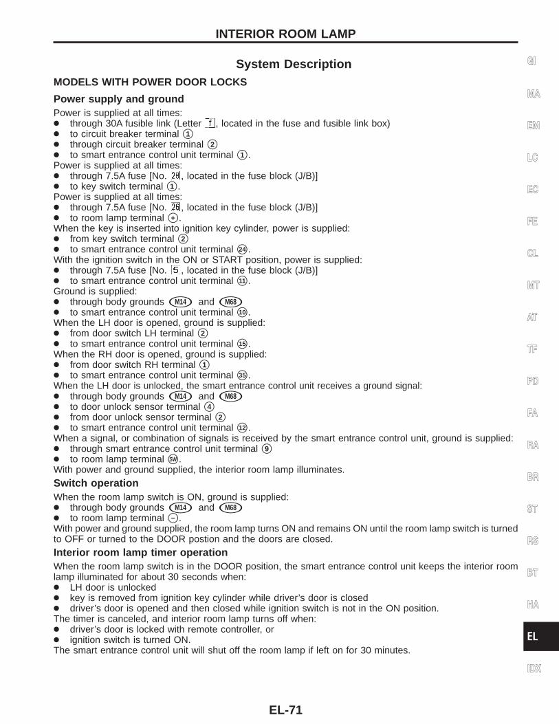
System DescriptionMODELS WITH POWER DOOR LOCKS
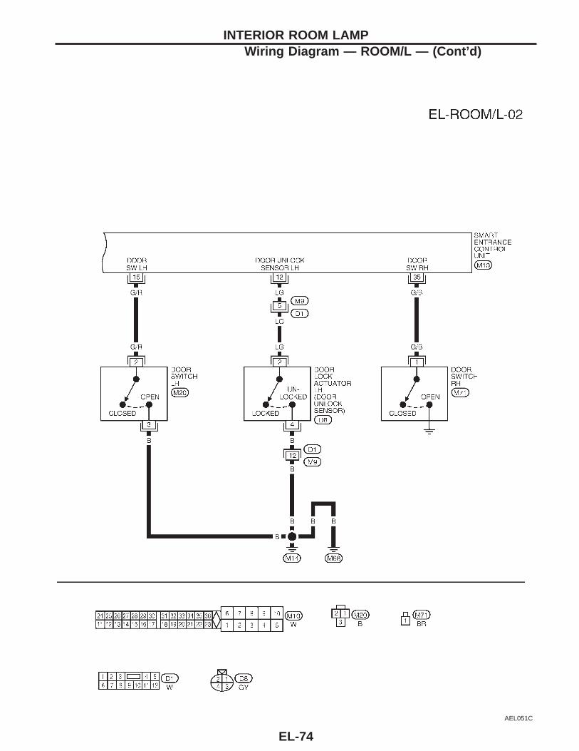
Power supply and groundPower is supplied at all times:● through 30A fusible link (Letter , located in the fuse and fusible link box)● to circuit breaker terminal s1● through circuit breaker terminal s2● to smart entrance control unit terminal s1 .Power is supplied at all times:● through 7.5A fuse [No. , located in the fuse block (J/B)]● to key switch terminal s1 .Power is supplied at all times:● through 7.5A fuse [No. , located in the fuse block (J/B)]● to room lamp terminal s+ .When the key is inserted into ignition key cylinder, power is supplied:● from key switch terminal s2● to smart entrance control unit terminal s24 .With the ignition switch in the ON or START position, power is supplied:● through 7.5A fuse [No. , located in the fuse block (J/B)]● to smart entrance control unit terminal s11 .Ground is supplied:● through body grounds sM14 and sM68● to smart entrance control unit terminal s10 .When the LH door is opened, ground is supplied:● from door switch LH terminal s2● to smart entrance control unit terminal s15 .When the RH door is opened, ground is supplied:● from door switch RH terminal s1● to smart entrance control unit terminal s35 .When the LH door is unlocked, the smart entrance control unit receives a ground signal:● through body grounds sM14 and sM68● to door unlock sensor terminal s4● from door unlock sensor terminal s2● to smart entrance control unit terminal s12 .When a signal, or combination of signals is received by the smart entrance control unit, ground is supplied:● through smart entrance control unit terminal s9● to room lamp terminal sSW .With power and ground supplied, the interior room lamp illuminates.Switch operationWhen the room lamp switch is ON, ground is supplied:● through body grounds sM14 and sM68● to room lamp terminal s− .With power and ground supplied, the room lamp turns ON and remains ON until the room lamp switch is turnedto OFF or turned to the DOOR postion and the doors are closed.Interior room lamp timer operationWhen the room lamp switch is in the DOOR position, the smart entrance control unit keeps the interior roomlamp illuminated for about 30 seconds when:● LH door is unlocked● key is removed from ignition key cylinder while driver’s door is closed● driver’s door is opened and then closed while ignition switch is not in the ON position.The timer is canceled, and interior room lamp turns off when:● driver’s door is locked with remote controller, or● ignition switch is turned ON.The smart entrance control unit will shut off the room lamp if left on for 30 minutes.
GI
MA
EM
LC
EC
FE
CL
MT
AT
TF
PD
FA
RA
BR
ST
RS
BT
HA
EL
IDX
INTERIOR ROOM LAMP
EL-71
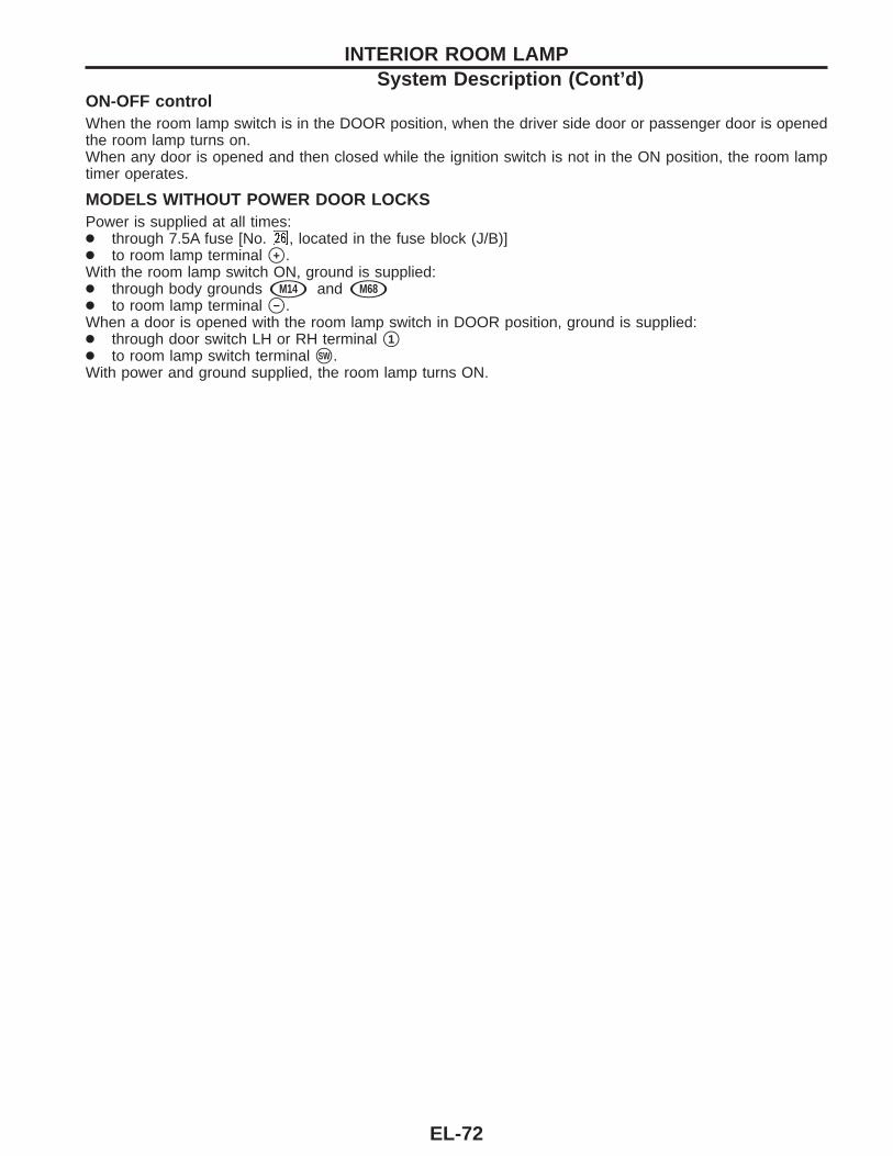
ON-OFF controlWhen the room lamp switch is in the DOOR position, when the driver side door or passenger door is openedthe room lamp turns on.When any door is opened and then closed while the ignition switch is not in the ON position, the room lamptimer operates.
MODELS WITHOUT POWER DOOR LOCKSPower is supplied at all times:● through 7.5A fuse [No. , located in the fuse block (J/B)]● to room lamp terminal s+ .With the room lamp switch ON, ground is supplied:● through body grounds sM14 and sM68● to room lamp terminal s− .When a door is opened with the room lamp switch in DOOR position, ground is supplied:● through door switch LH or RH terminal s1● to room lamp switch terminal sSW .With power and ground supplied, the room lamp turns ON.
INTERIOR ROOM LAMPSystem Description (Cont’d)
EL-72
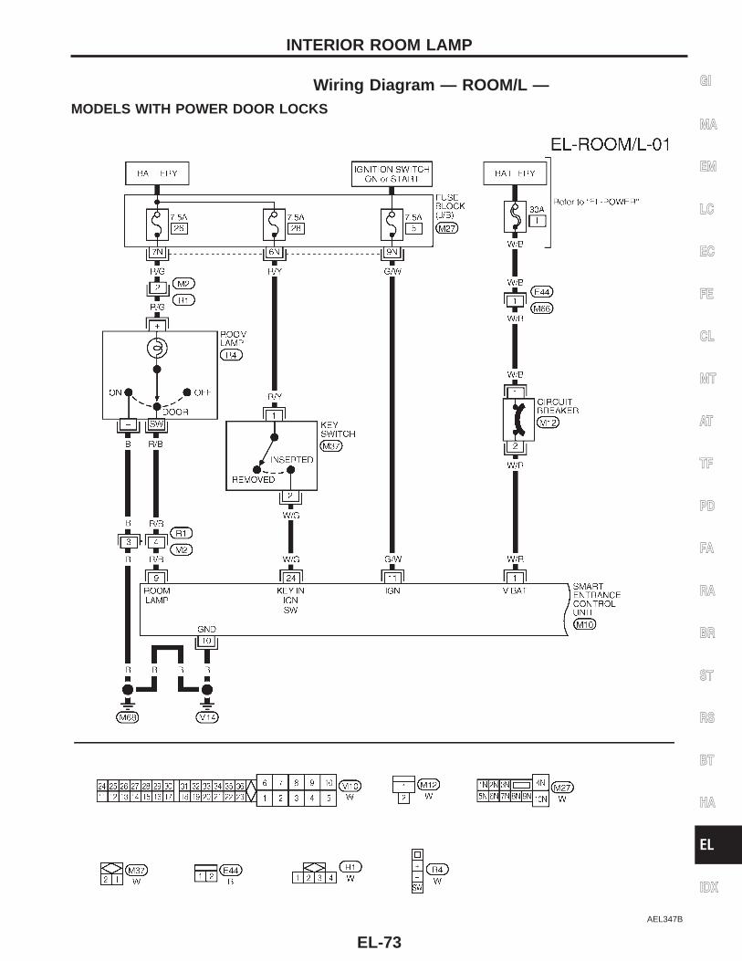
Wiring Diagram — ROOM/L —MODELS WITH POWER DOOR LOCKS
AEL347B
GI
MA
EM
LC
EC
FE
CL
MT
AT
TF
PD
FA
RA
BR
ST
RS
BT
HA
EL
IDX
INTERIOR ROOM LAMP
EL-73
AEL051C
INTERIOR ROOM LAMPWiring Diagram — ROOM/L — (Cont’d)
EL-74
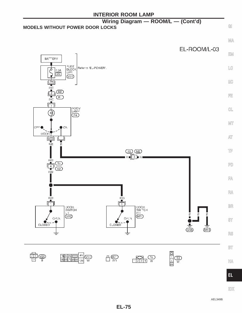
MODELS WITHOUT POWER DOOR LOCKS
AEL349B
GI
MA
EM
LC
EC
FE
CL
MT
AT
TF
PD
FA
RA
BR
ST
RS
BT
HA
EL
IDX
INTERIOR ROOM LAMPWiring Diagram — ROOM/L — (Cont’d)
EL-75
AEL365B
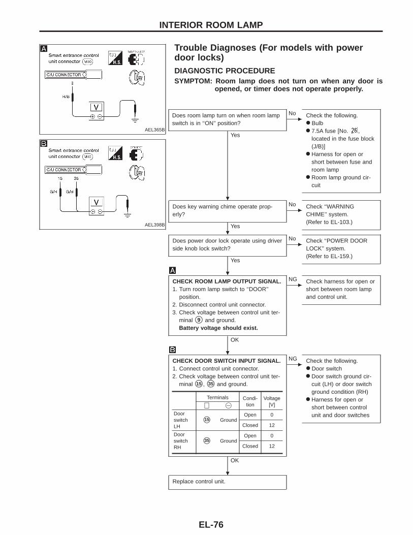
Trouble Diagnoses (For models with powerdoor locks)DIAGNOSTIC PROCEDURESYMPTOM: Room lamp does not turn on when any door is
opened, or timer does not operate properly.
AEL398B
Does room lamp turn on when room lampswitch is in ‘‘ON’’ position?
Yes
c
No Check the following.● Bulb● 7.5A fuse [No. ,
located in the fuse block(J/B)]
● Harness for open orshort between fuse androom lamp
● Room lamp ground cir-cuit
Does key warning chime operate prop-erly?
Yes
c
No Check ‘‘WARNINGCHIME’’ system.(Refer to EL-103.)
Does power door lock operate using driverside knob lock switch?
Yes
c
No Check ‘‘POWER DOORLOCK’’ system.(Refer to EL-159.)
CHECK ROOM LAMP OUTPUT SIGNAL.1. Turn room lamp switch to ‘‘DOOR’’
position.2. Disconnect control unit connector.3. Check voltage between control unit ter-
minal s9 and ground.Battery voltage should exist.
OK
c
NG Check harness for open orshort between room lampand control unit.
CHECK DOOR SWITCH INPUT SIGNAL.1. Connect control unit connector.2. Check voltage between control unit ter-
minal s15 , s35 and ground.
OK
c
NG Check the following.● Door switch● Door switch ground cir-
cuit (LH) or door switchground condition (RH)
● Harness for open orshort between controlunit and door switches
Replace control unit.
Terminals Condi-tion
Voltage[V]⊕ @
DoorswitchLH
s15 GroundOpen 0
Closed 12
DoorswitchRH
s35 GroundOpen 0
Closed 12
INTERIOR ROOM LAMP
.
.
.
.
.
EL-76
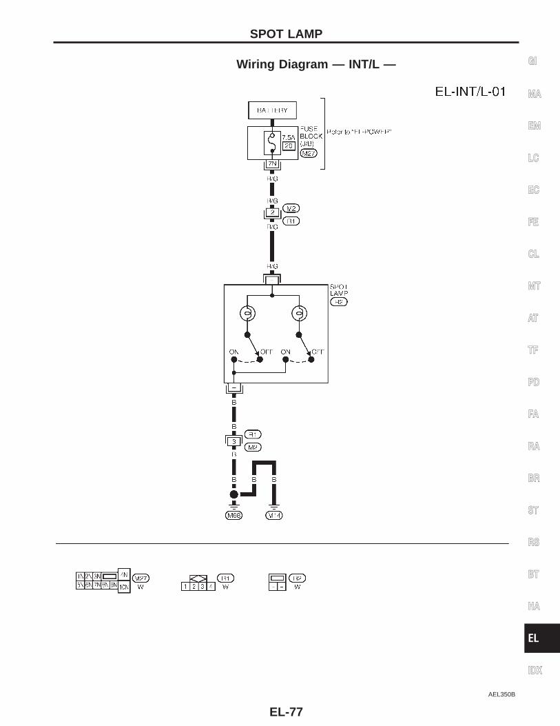
Wiring Diagram — INT/L —
AEL350B
GI
MA
EM
LC
EC
FE
CL
MT
AT
TF
PD
FA
RA
BR
ST
RS
BT
HA
EL
IDX
SPOT LAMP
EL-77
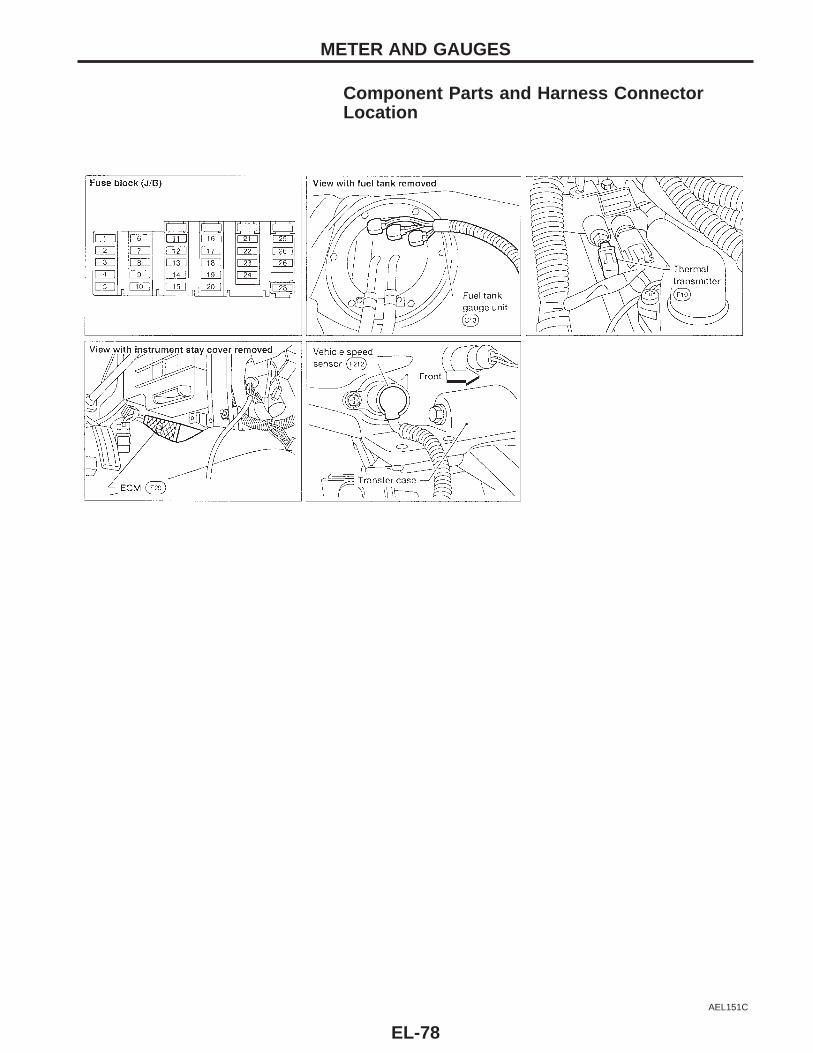
Component Parts and Harness ConnectorLocation
AEL151C
METER AND GAUGES
EL-78
System DescriptionUNIFIED CONTROL METER● Speedometer, odo/trip meter, tachometer, fuel gauge and water temperature gauge are controlled totally
by control unit combined with speedometer.● Digital meter is adopted for odo/trip meter.*
*The record of the odo meter is kept even if the battery cable is disconnected. The record of the trip meteris erased when the battery cable is disconnected.
● Odo/trip meter segment can be checked in diagnosis mode.● Meter/gauge can be checked in diagnosis mode.
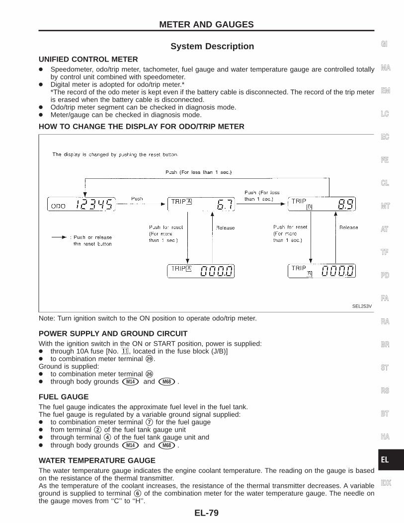
HOW TO CHANGE THE DISPLAY FOR ODO/TRIP METER
SEL253V
Note: Turn ignition switch to the ON position to operate odo/trip meter.
POWER SUPPLY AND GROUND CIRCUITWith the ignition switch in the ON or START position, power is supplied:● through 10A fuse [No. , located in the fuse block (J/B)]● to combination meter terminal s29 .Ground is supplied:● to combination meter terminal s26
● through body grounds sM14 and sM68 .
FUEL GAUGEThe fuel gauge indicates the approximate fuel level in the fuel tank.The fuel gauge is regulated by a variable ground signal supplied:● to combination meter terminal s7 for the fuel gauge● from terminal s2 of the fuel tank gauge unit● through terminal s4 of the fuel tank gauge unit and● through body grounds sM14 and sM68 .
WATER TEMPERATURE GAUGEThe water temperature gauge indicates the engine coolant temperature. The reading on the gauge is basedon the resistance of the thermal transmitter.As the temperature of the coolant increases, the resistance of the thermal transmitter decreases. A variableground is supplied to terminal s6 of the combination meter for the water temperature gauge. The needle onthe gauge moves from ‘‘C’’ to ‘‘H’’.
GI
MA
EM
LC
EC
FE
CL
MT
AT
TF
PD
FA
RA
BR
ST
RS
BT
HA
EL
IDX
METER AND GAUGES
EL-79
TACHOMETERThe tachometer indicates engine speed in revolutions per minute (rpm).The tachometer is regulated by a signal:● from terminal s3 of the ECM● to combination meter terminal s9 for the tachometer.
SPEEDOMETERThe vehicle speed sensor provides a voltage signal to the combination meter for the speedometer.The voltage is supplied:● to combination meter terminals s8 and s10 for the speedometer● from terminals s2 and s1 of the vehicle speed sensor.The speedometer converts the voltage into the vehicle speed displayed.
METER AND GAUGESSystem Description (Cont’d)
EL-80
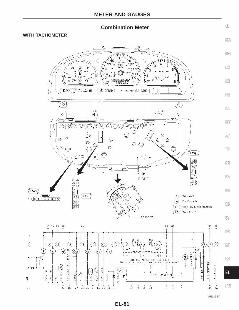
Combination MeterWITH TACHOMETER
AEL152C
GI
MA
EM
LC
EC
FE
CL
MT
AT
TF
PD
FA
RA
BR
ST
RS
BT
HA
EL
IDX
METER AND GAUGES
EL-81
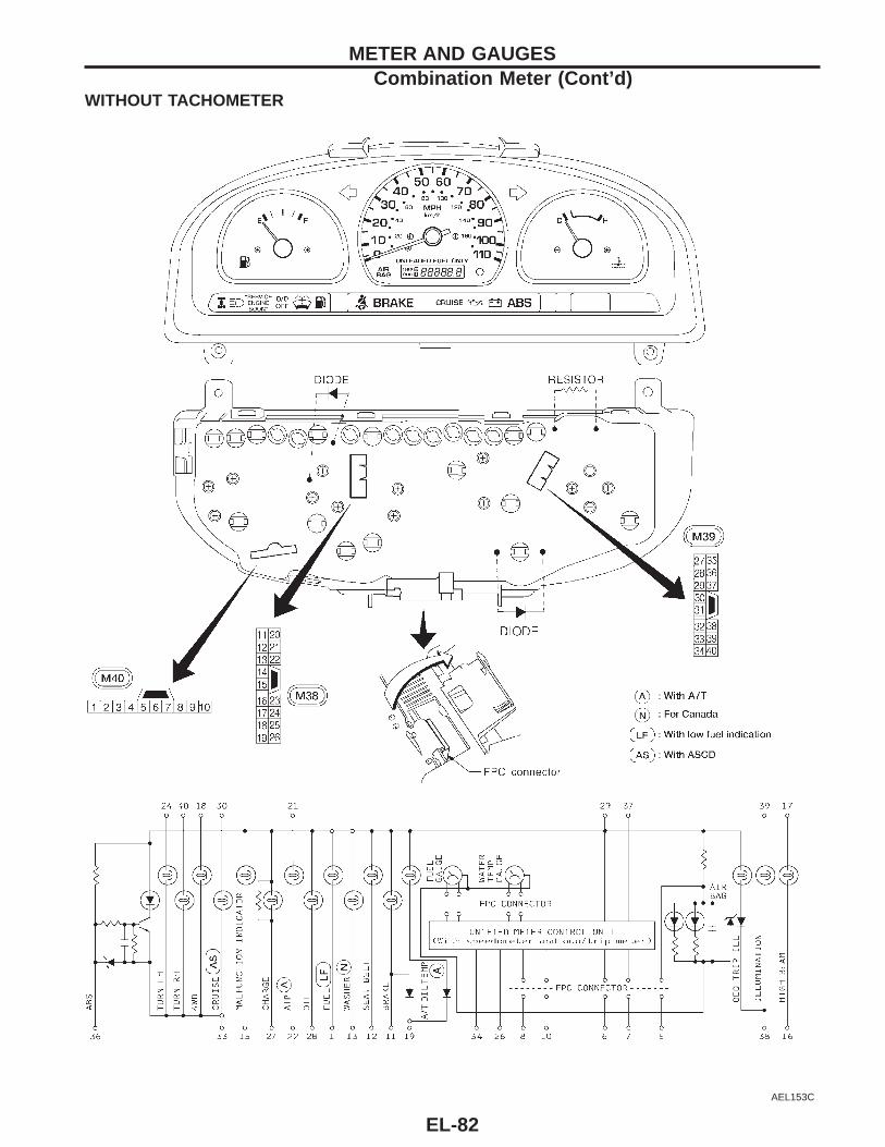
WITHOUT TACHOMETER
AEL153C
METER AND GAUGESCombination Meter (Cont’d)
EL-82
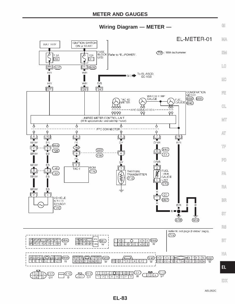
Wiring Diagram — METER —
AEL052C
GI
MA
EM
LC
EC
FE
CL
MT
AT
TF
PD
FA
RA
BR
ST
RS
BT
HA
EL
IDX
METER AND GAUGES
EL-83
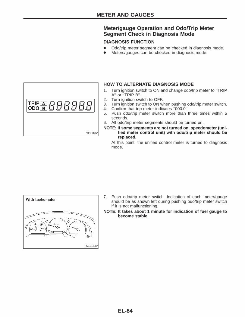
Meter/gauge Operation and Odo/Trip MeterSegment Check in Diagnosis ModeDIAGNOSIS FUNCTION● Odo/trip meter segment can be checked in diagnosis mode.● Meters/gauges can be checked in diagnosis mode.
SEL110V
HOW TO ALTERNATE DIAGNOSIS MODE1. Turn ignition switch to ON and change odo/trip meter to ‘‘TRIP
A’’ or ‘‘TRIP B’’.2. Turn ignition switch to OFF.3. Turn ignition switch to ON when pushing odo/trip meter switch.4. Confirm that trip meter indicates ‘‘000.0’’.5. Push odo/trip meter switch more than three times within 5
seconds.6. All odo/trip meter segments should be turned on.NOTE: If some segments are not turned on, speedometer (uni-
fied meter control unit) with odo/trip meter should bereplaced.
At this point, the unified control meter is turned to diagnosismode.
SEL163V
7. Push odo/trip meter switch. Indication of each meter/gaugeshould be as shown left during pushing odo/trip meter switchif it is not malfunctioning.
NOTE: It takes about 1 minute for indication of fuel gauge tobecome stable.
METER AND GAUGES
EL-84
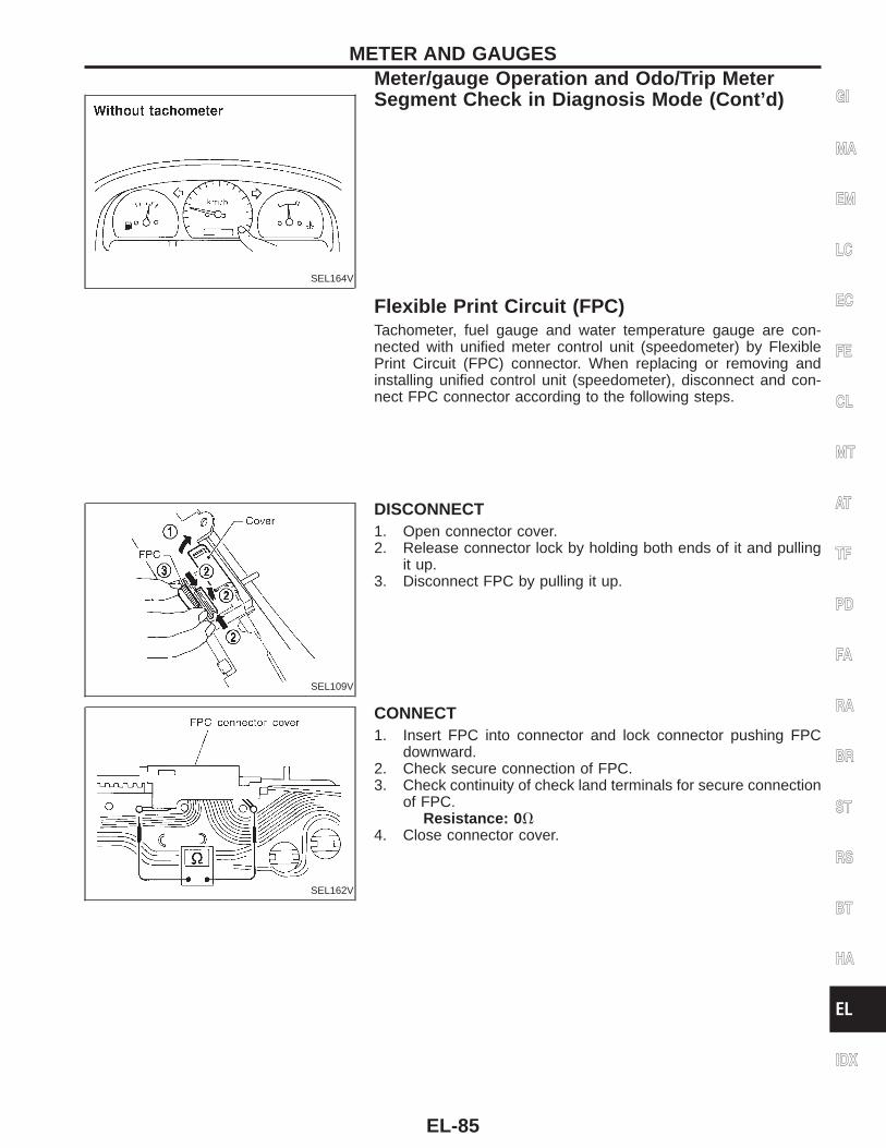
SEL164V
Flexible Print Circuit (FPC)Tachometer, fuel gauge and water temperature gauge are con-nected with unified meter control unit (speedometer) by FlexiblePrint Circuit (FPC) connector. When replacing or removing andinstalling unified control unit (speedometer), disconnect and con-nect FPC connector according to the following steps.
SEL109V
DISCONNECT1. Open connector cover.2. Release connector lock by holding both ends of it and pulling
it up.3. Disconnect FPC by pulling it up.
SEL162V
CONNECT1. Insert FPC into connector and lock connector pushing FPC
downward.2. Check secure connection of FPC.3. Check continuity of check land terminals for secure connection
of FPC.Resistance: 0 V
4. Close connector cover.
GI
MA
EM
LC
EC
FE
CL
MT
AT
TF
PD
FA
RA
BR
ST
RS
BT
HA
EL
IDX
METER AND GAUGESMeter/gauge Operation and Odo/Trip MeterSegment Check in Diagnosis Mode (Cont’d)
EL-85
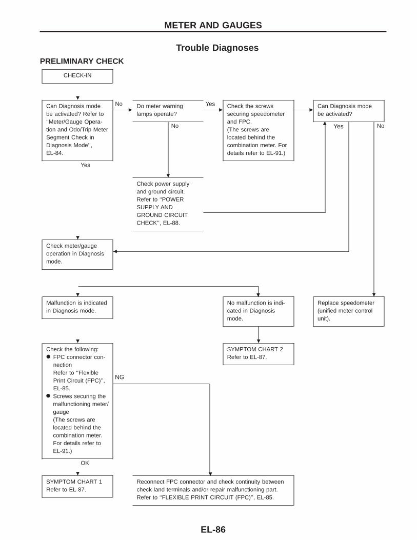
Trouble DiagnosesPRELIMINARY CHECK
CHECK-IN
Can Diagnosis modebe activated? Refer to‘‘Meter/Gauge Opera-tion and Odo/Trip MeterSegment Check inDiagnosis Mode’’,EL-84.
Yes
c
No Do meter warninglamps operate?
No
c
Yes Check the screwssecuring speedometerand FPC.(The screws arelocated behind thecombination meter. Fordetails refer to EL-91.)
cCan Diagnosis modebe activated?
Nom
Check power supplyand ground circuit.Refer to ‘‘POWERSUPPLY ANDGROUND CIRCUITCHECK’’, EL-88.
Check meter/gaugeoperation in Diagnosismode.
b
Yes
.
Malfunction is indicatedin Diagnosis mode.
No malfunction is indi-cated in Diagnosismode.
Replace speedometer(unified meter controlunit).
Check the following:● FPC connector con-
nectionRefer to ‘‘FlexiblePrint Circuit (FPC)’’,EL-85.
● Screws securing themalfunctioning meter/gauge(The screws arelocated behind thecombination meter.For details refer toEL-91.)
OK
.
NG
SYMPTOM CHART 2Refer to EL-87.
SYMPTOM CHART 1Refer to EL-87.
Reconnect FPC connector and check continuity betweencheck land terminals and/or repair malfunctioning part.Refer to ‘‘FLEXIBLE PRINT CIRCUIT (FPC)’’, EL-85.
METER AND GAUGES
.
.
.
. .
. .
.
EL-86
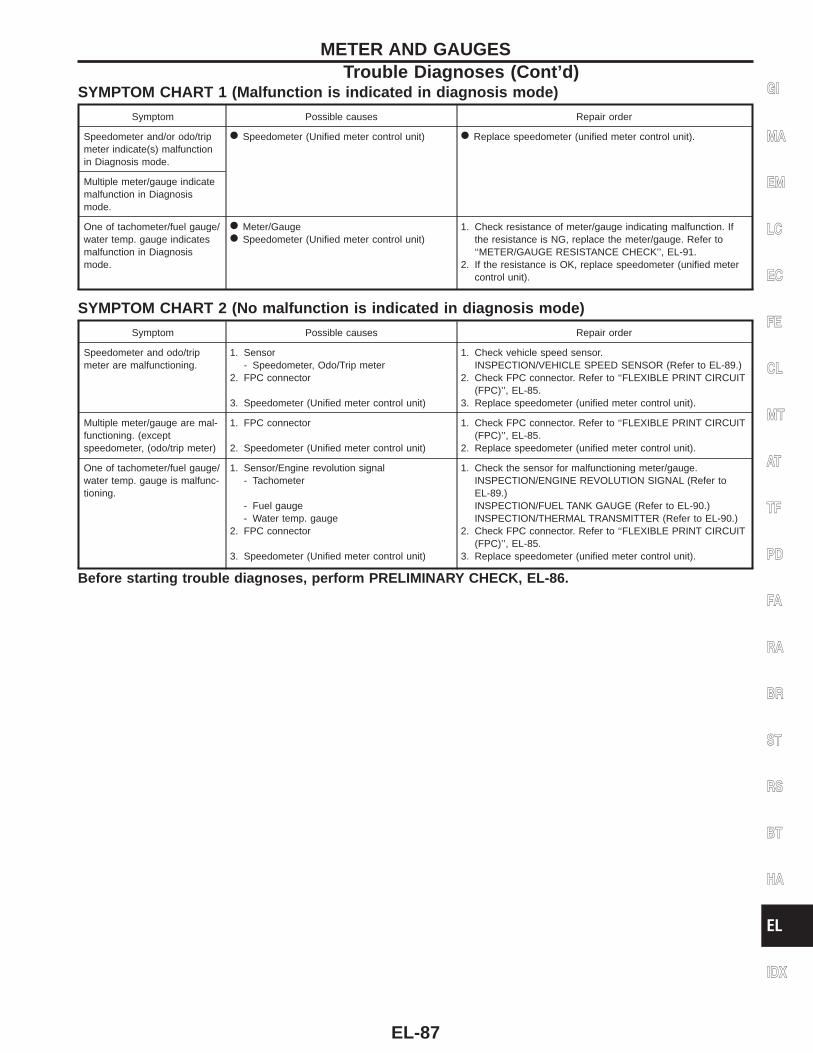
SYMPTOM CHART 1 (Malfunction is indicated in diagnosis mode)
Symptom Possible causes Repair order
Speedometer and/or odo/tripmeter indicate(s) malfunctionin Diagnosis mode.
● Speedometer (Unified meter control unit) ● Replace speedometer (unified meter control unit).
Multiple meter/gauge indicatemalfunction in Diagnosismode.
One of tachometer/fuel gauge/water temp. gauge indicatesmalfunction in Diagnosismode.
● Meter/Gauge● Speedometer (Unified meter control unit)
1. Check resistance of meter/gauge indicating malfunction. Ifthe resistance is NG, replace the meter/gauge. Refer to‘‘METER/GAUGE RESISTANCE CHECK’’, EL-91.
2. If the resistance is OK, replace speedometer (unified metercontrol unit).
SYMPTOM CHART 2 (No malfunction is indicated in diagnosis mode)
Symptom Possible causes Repair order
Speedometer and odo/tripmeter are malfunctioning.
1. Sensor- Speedometer, Odo/Trip meter
2. FPC connector
3. Speedometer (Unified meter control unit)
1. Check vehicle speed sensor.INSPECTION/VEHICLE SPEED SENSOR (Refer to EL-89.)
2. Check FPC connector. Refer to ‘‘FLEXIBLE PRINT CIRCUIT(FPC)’’, EL-85.
3. Replace speedometer (unified meter control unit).
Multiple meter/gauge are mal-functioning. (exceptspeedometer, (odo/trip meter)
1. FPC connector
2. Speedometer (Unified meter control unit)
1. Check FPC connector. Refer to ‘‘FLEXIBLE PRINT CIRCUIT(FPC)’’, EL-85.
2. Replace speedometer (unified meter control unit).
One of tachometer/fuel gauge/water temp. gauge is malfunc-tioning.
1. Sensor/Engine revolution signal- Tachometer
- Fuel gauge- Water temp. gauge
2. FPC connector
3. Speedometer (Unified meter control unit)
1. Check the sensor for malfunctioning meter/gauge.INSPECTION/ENGINE REVOLUTION SIGNAL (Refer toEL-89.)INSPECTION/FUEL TANK GAUGE (Refer to EL-90.)INSPECTION/THERMAL TRANSMITTER (Refer to EL-90.)
2. Check FPC connector. Refer to ‘‘FLEXIBLE PRINT CIRCUIT(FPC)’’, EL-85.
3. Replace speedometer (unified meter control unit).
Before starting trouble diagnoses, perform PRELIMINARY CHECK, EL-86.
GI
MA
EM
LC
EC
FE
CL
MT
AT
TF
PD
FA
RA
BR
ST
RS
BT
HA
EL
IDX
METER AND GAUGESTrouble Diagnoses (Cont’d)
EL-87
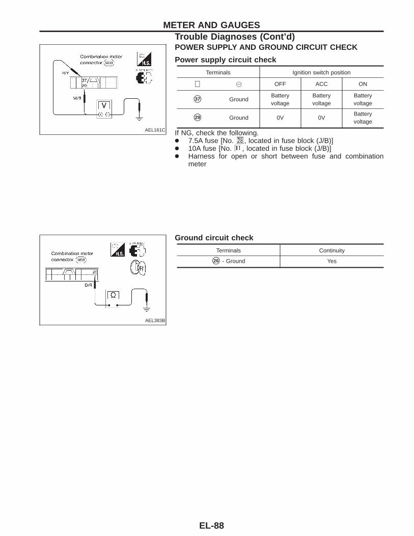
AEL161C
POWER SUPPLY AND GROUND CIRCUIT CHECK
Power supply circuit check
Terminals Ignition switch position
⊕ @ OFF ACC ON
s37 GroundBatteryvoltage
Batteryvoltage
Batteryvoltage
s29 Ground 0V 0VBatteryvoltage
If NG, check the following.● 7.5A fuse [No. , located in fuse block (J/B)]● 10A fuse [No. , located in fuse block (J/B)]● Harness for open or short between fuse and combination
meter
AEL383B
Ground circuit check
Terminals Continuity
s26 - Ground Yes
METER AND GAUGESTrouble Diagnoses (Cont’d)
EL-88
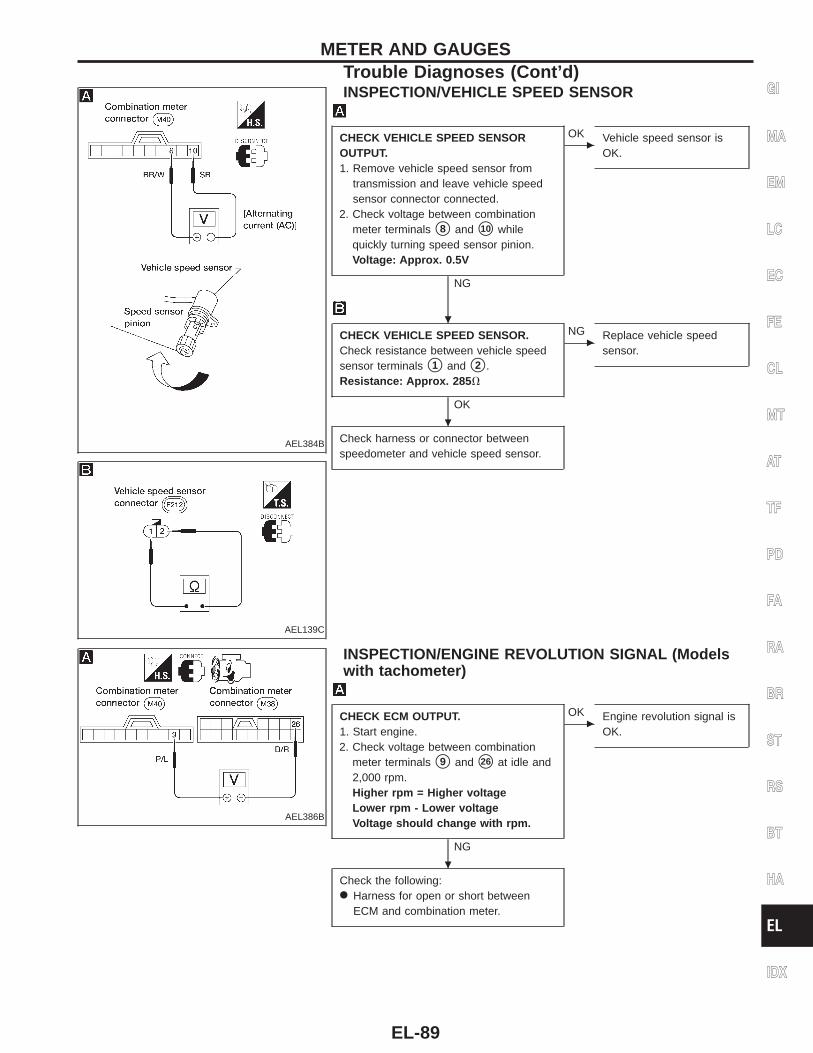
AEL384B
AEL139C
INSPECTION/VEHICLE SPEED SENSOR
CHECK VEHICLE SPEED SENSOROUTPUT.1. Remove vehicle speed sensor from
transmission and leave vehicle speedsensor connector connected.
2. Check voltage between combinationmeter terminals s8 and s10 whilequickly turning speed sensor pinion.Voltage: Approx. 0.5V
NG
c
OK Vehicle speed sensor isOK.
CHECK VEHICLE SPEED SENSOR.Check resistance between vehicle speedsensor terminals s1 and s2 .Resistance: Approx. 285 V
OK
c
NG Replace vehicle speedsensor.
Check harness or connector betweenspeedometer and vehicle speed sensor.
AEL386B
INSPECTION/ENGINE REVOLUTION SIGNAL (Modelswith tachometer)
CHECK ECM OUTPUT.1. Start engine.2. Check voltage between combination
meter terminals s9 and s26 at idle and2,000 rpm.Higher rpm = Higher voltageLower rpm - Lower voltageVoltage should change with rpm.
NG
c
OK Engine revolution signal isOK.
Check the following:● Harness for open or short between
ECM and combination meter.
GI
MA
EM
LC
EC
FE
CL
MT
AT
TF
PD
FA
RA
BR
ST
RS
BT
HA
EL
IDX
METER AND GAUGESTrouble Diagnoses (Cont’d)
.
.
.
EL-89
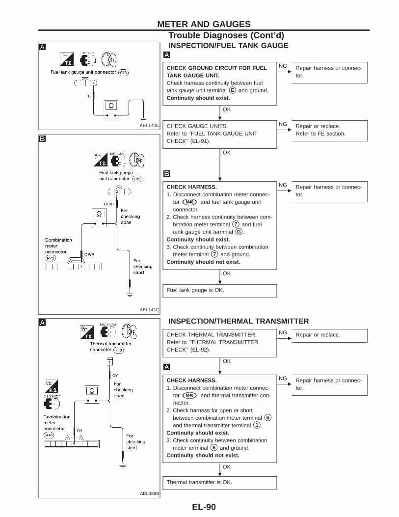
AEL140C
AEL141C
INSPECTION/FUEL TANK GAUGE
CHECK GROUND CIRCUIT FOR FUELTANK GAUGE UNIT.Check harness continuity between fueltank gauge unit terminal sE and ground.Continuity should exist.
OK
c
NG Repair harness or connec-tor.
CHECK GAUGE UNITS.Refer to ‘‘FUEL TANK GAUGE UNITCHECK’’ (EL-91).
OK
c
NG Repair or replace.Refer to FE section.
CHECK HARNESS.1. Disconnect combination meter connec-
tor sM40 and fuel tank gauge unitconnector.
2. Check harness continuity between com-bination meter terminal s7 and fueltank gauge unit terminal sG .
Continuity should exist.3. Check continuity between combination
meter terminal s7 and ground.Continuity should not exist.
OK
c
NG Repair harness or connec-tor.
Fuel tank gauge is OK.
AEL389B
INSPECTION/THERMAL TRANSMITTER
CHECK THERMAL TRANSMITTER.Refer to ‘‘THERMAL TRANSMITTERCHECK’’ (EL-92).
OK
c
NG Repair or replace.
CHECK HARNESS.1. Disconnect combination meter connec-
tor sM40 and thermal transmitter con-nector.
2. Check harness for open or shortbetween combination meter terminal s6
and thermal transmitter terminal s1 .Continuity should exist.3. Check continuity between combination
meter terminal s6 and ground.Continuity should not exist.
OK
c
NG Repair harness or connec-tor.
Thermal transmitter is OK.
METER AND GAUGESTrouble Diagnoses (Cont’d)
.
.
.
.
.
EL-90
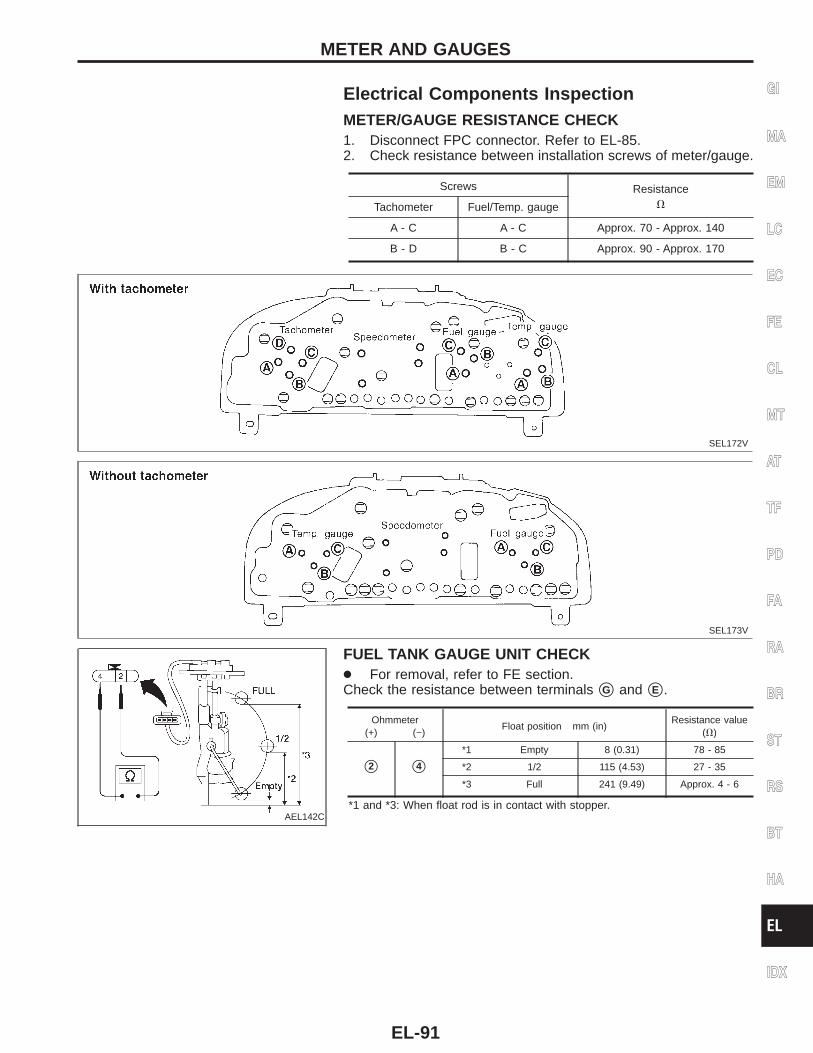
Electrical Components InspectionMETER/GAUGE RESISTANCE CHECK1. Disconnect FPC connector. Refer to EL-85.2. Check resistance between installation screws of meter/gauge.
Screws ResistanceVTachometer Fuel/Temp. gauge
A - C A - C Approx. 70 - Approx. 140
B - D B - C Approx. 90 - Approx. 170
SEL172V
SEL173V
AEL142C
FUEL TANK GAUGE UNIT CHECK● For removal, refer to FE section.Check the resistance between terminals sG and sE .
Ohmmeter(+) (−)
Float position mm (in)Resistance value
(V)
s2 s4
*1 Empty 8 (0.31) 78 - 85
*2 1/2 115 (4.53) 27 - 35
*3 Full 241 (9.49) Approx. 4 - 6
*1 and *3: When float rod is in contact with stopper.
GI
MA
EM
LC
EC
FE
CL
MT
AT
TF
PD
FA
RA
BR
ST
RS
BT
HA
EL
IDX
METER AND GAUGES
EL-91
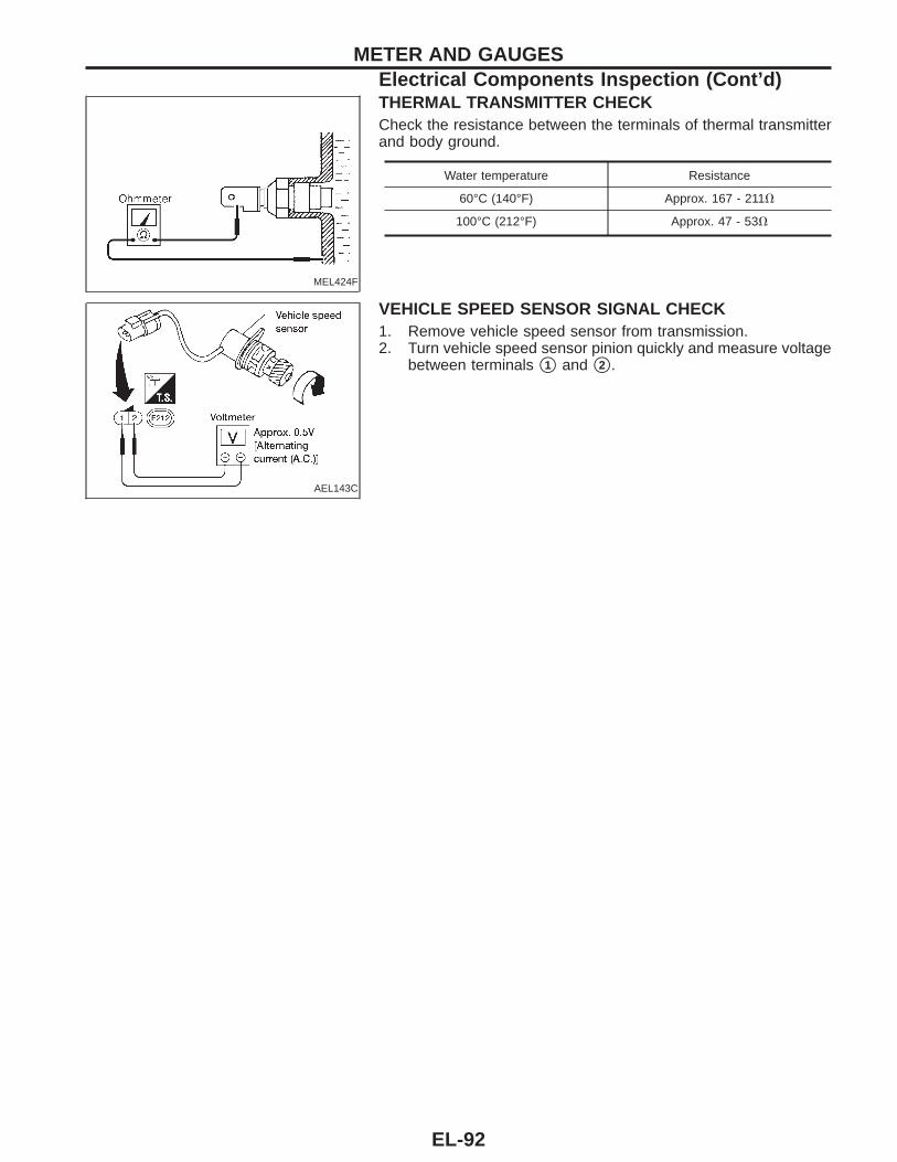
MEL424F
THERMAL TRANSMITTER CHECKCheck the resistance between the terminals of thermal transmitterand body ground.
Water temperature Resistance
60°C (140°F) Approx. 167 - 211V
100°C (212°F) Approx. 47 - 53V
AEL143C
VEHICLE SPEED SENSOR SIGNAL CHECK1. Remove vehicle speed sensor from transmission.2. Turn vehicle speed sensor pinion quickly and measure voltage
between terminals s1 and s2 .
METER AND GAUGESElectrical Components Inspection (Cont’d)
EL-92
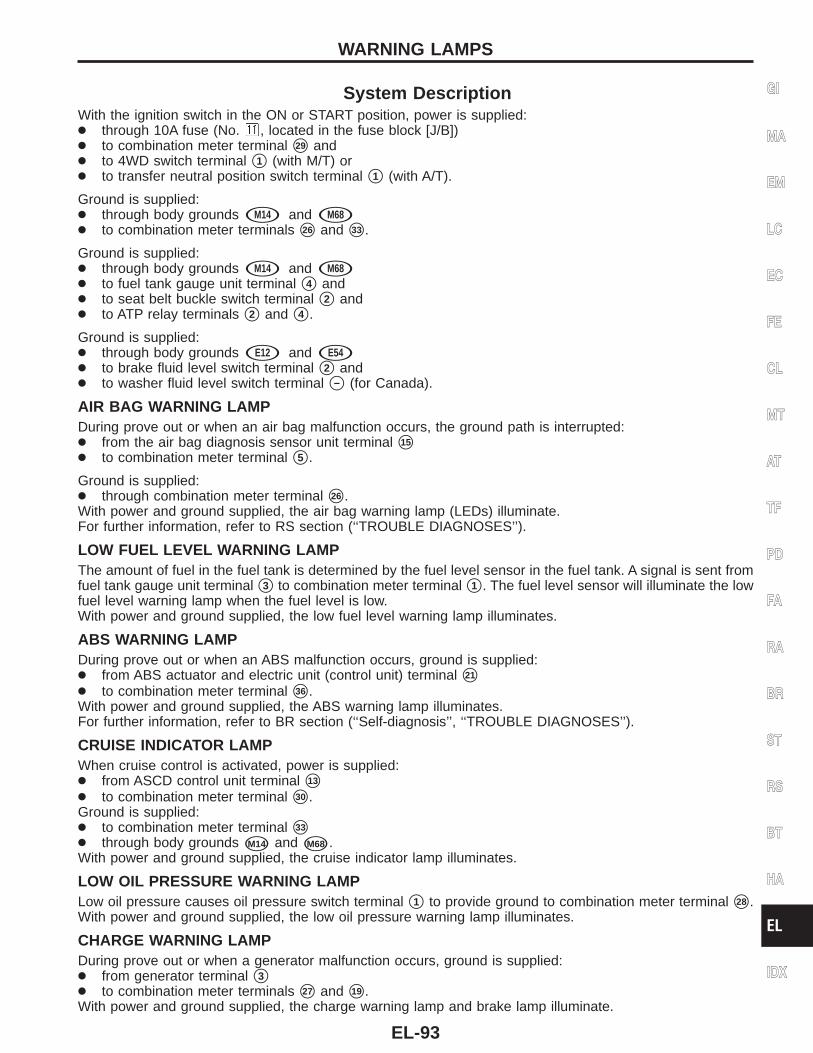
System DescriptionWith the ignition switch in the ON or START position, power is supplied:● through 10A fuse (No. , located in the fuse block [J/B])● to combination meter terminal s29 and● to 4WD switch terminal s1 (with M/T) or● to transfer neutral position switch terminal s1 (with A/T).
Ground is supplied:● through body grounds sM14 and sM68● to combination meter terminals s26 and s33 .
Ground is supplied:● through body grounds sM14 and sM68● to fuel tank gauge unit terminal s4 and● to seat belt buckle switch terminal s2 and● to ATP relay terminals s2 and s4 .
Ground is supplied:● through body grounds sE12 and sE54● to brake fluid level switch terminal s2 and● to washer fluid level switch terminal s− (for Canada).
AIR BAG WARNING LAMPDuring prove out or when an air bag malfunction occurs, the ground path is interrupted:● from the air bag diagnosis sensor unit terminal s15
● to combination meter terminal s5 .
Ground is supplied:● through combination meter terminal s26 .With power and ground supplied, the air bag warning lamp (LEDs) illuminate.For further information, refer to RS section (‘‘TROUBLE DIAGNOSES’’).
LOW FUEL LEVEL WARNING LAMPThe amount of fuel in the fuel tank is determined by the fuel level sensor in the fuel tank. A signal is sent fromfuel tank gauge unit terminal s3 to combination meter terminal s1 . The fuel level sensor will illuminate the lowfuel level warning lamp when the fuel level is low.With power and ground supplied, the low fuel level warning lamp illuminates.
ABS WARNING LAMPDuring prove out or when an ABS malfunction occurs, ground is supplied:● from ABS actuator and electric unit (control unit) terminal s21
● to combination meter terminal s36 .With power and ground supplied, the ABS warning lamp illuminates.For further information, refer to BR section (‘‘Self-diagnosis’’, ‘‘TROUBLE DIAGNOSES’’).
CRUISE INDICATOR LAMPWhen cruise control is activated, power is supplied:● from ASCD control unit terminal s13
● to combination meter terminal s30 .Ground is supplied:● to combination meter terminal s33
● through body grounds sM14 and sM68 .With power and ground supplied, the cruise indicator lamp illuminates.
LOW OIL PRESSURE WARNING LAMPLow oil pressure causes oil pressure switch terminal s1 to provide ground to combination meter terminal s28 .With power and ground supplied, the low oil pressure warning lamp illuminates.
CHARGE WARNING LAMPDuring prove out or when a generator malfunction occurs, ground is supplied:● from generator terminal s3● to combination meter terminals s27 and s19 .With power and ground supplied, the charge warning lamp and brake lamp illuminate.
GI
MA
EM
LC
EC
FE
CL
MT
AT
TF
PD
FA
RA
BR
ST
RS
BT
HA
EL
IDX
WARNING LAMPS
EL-93
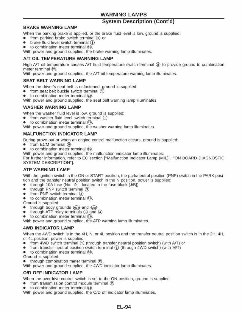
BRAKE WARNING LAMPWhen the parking brake is applied, or the brake fluid level is low, ground is supplied:● from parking brake switch terminal s1 or● brake fluid level switch terminal s1● to combination meter terminal s11 .With power and ground supplied, the brake warning lamp illuminates.
A/T OIL TEMPERATURE WARNING LAMPHigh A/T oil temperature causes A/T fluid temperature switch terminal s8 to provide ground to combinationmeter terminal s20 .With power and ground supplied, the A/T oil temperature warning lamp illuminates.
SEAT BELT WARNING LAMPWhen the driver’s seat belt is unfastened, ground is supplied:● from seat belt buckle switch terminal s1● to combination meter terminal s12 .With power and ground supplied, the seat belt warning lamp illuminates.
WASHER WARNING LAMPWhen the washer fluid level is low, ground is supplied:● from washer fluid level switch terminal s+● to combination meter terminal s13 .With power and ground supplied, the washer warning lamp illuminates.
MALFUNCTION INDICATOR LAMPDuring prove out or when an engine control malfunction occurs, ground is supplied:● from ECM terminal s18
● to combination meter terminal s15 .With power and ground supplied, the malfunction indicator lamp illuminates.For further information, refer to EC section [‘‘Malfunction Indicator Lamp (MIL)’’, ‘‘ON BOARD DIAGNOSTICSYSTEM DESCRIPTION’’].
ATP WARNING LAMPWith the ignition switch in the ON or START position, the park/neutral position (PNP) switch in the PARK posi-tion and the transfer neutral position switch in the N position, power is supplied:● through 10A fuse (No. , located in the fuse block [J/B])● through PNP switch terminal s3● from PNP switch terminal s4● to combination meter terminal s21 .Ground is supplied:● through body grounds sM14 and sM68
● through ATP relay terminals s3 and s4● to combination meter terminal s22 .With power and ground supplied, the ATP warning lamp illuminates.
4WD INDICATOR LAMPWhen the 4WD switch is in the 4H, N, or 4L position and the transfer neutral position switch is in the 2H, 4H,or 4L position, power is supplied:● from 4WD switch terminal s1 (through transfer neutral position switch) (with A/T) or● from transfer neutral position switch terminal s1 (through 4WD switch) (with M/T)● to combination meter terminal s18 .Ground is supplied:● through combination meter terminal s33 .With power and ground supplied, the 4WD indicator lamp illuminates.
O/D OFF INDICATOR LAMPWhen the overdrive control switch is set to the ON position, ground is supplied:● from transmission control module terminal s13
● to combination meter terminal s14 .With power and ground supplied, the O/D off indicator lamp illuminates.
WARNING LAMPSSystem Description (Cont’d)
EL-94
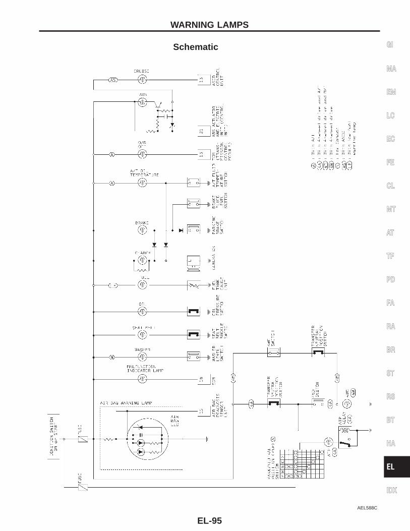
Schematic
AEL588C
GI
MA
EM
LC
EC
FE
CL
MT
AT
TF
PD
FA
RA
BR
ST
RS
BT
HA
EL
IDX
WARNING LAMPS
EL-95
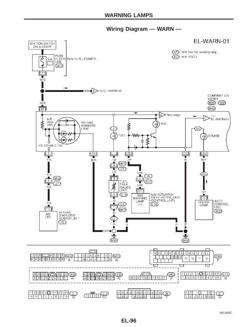
Wiring Diagram — WARN —
AEL665C
WARNING LAMPS
EL-96
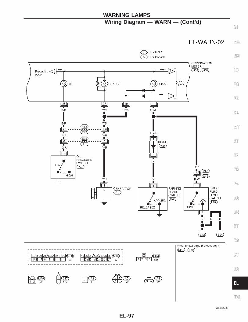
AEL055C
GI
MA
EM
LC
EC
FE
CL
MT
AT
TF
PD
FA
RA
BR
ST
RS
BT
HA
EL
IDX
WARNING LAMPSWiring Diagram — WARN — (Cont’d)
EL-97
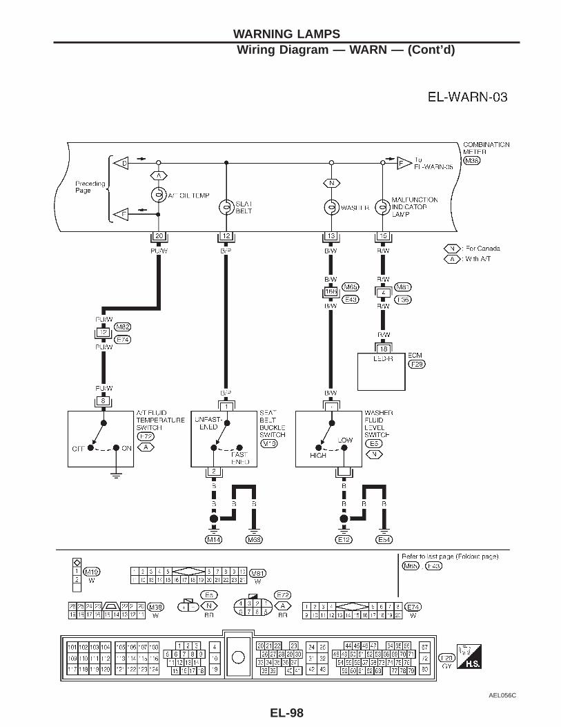
AEL056C
WARNING LAMPSWiring Diagram — WARN — (Cont’d)
EL-98
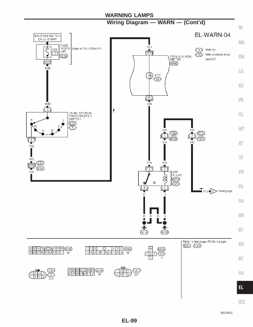
AEL591C
GI
MA
EM
LC
EC
FE
CL
MT
AT
TF
PD
FA
RA
BR
ST
RS
BT
HA
EL
IDX
WARNING LAMPSWiring Diagram — WARN — (Cont’d)
EL-99
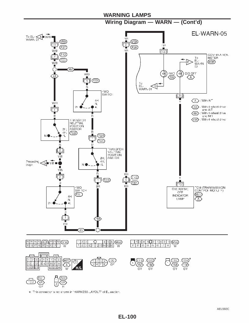
AEL592C
WARNING LAMPSWiring Diagram — WARN — (Cont’d)
EL-100
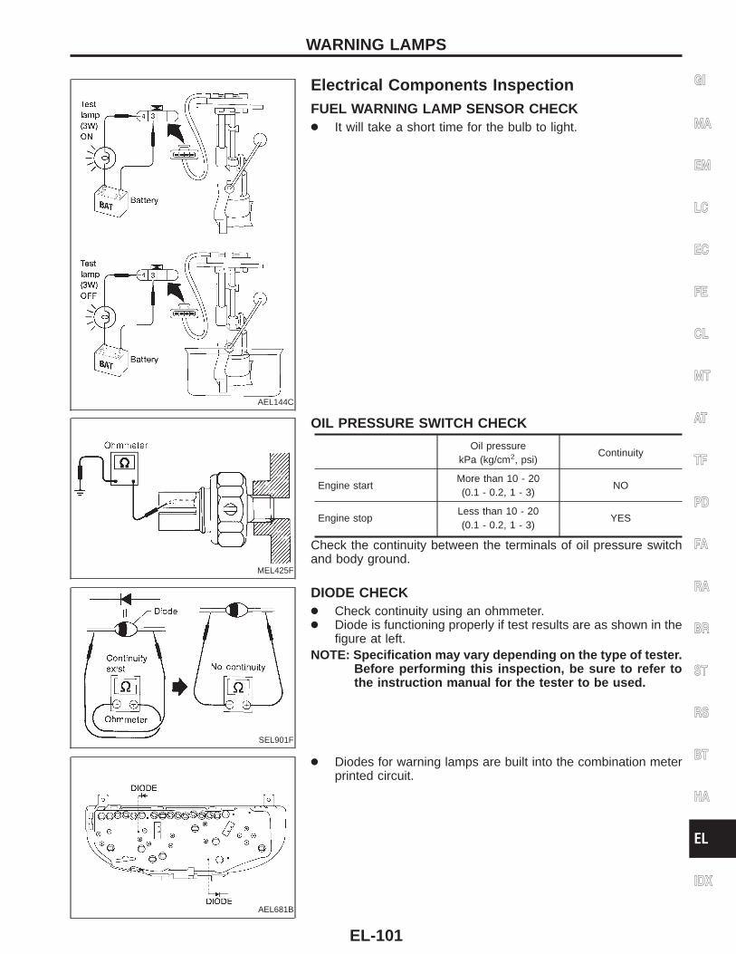
AEL144C
Electrical Components InspectionFUEL WARNING LAMP SENSOR CHECK● It will take a short time for the bulb to light.
MEL425F
OIL PRESSURE SWITCH CHECK
Oil pressurekPa (kg/cm2, psi)
Continuity
Engine startMore than 10 - 20(0.1 - 0.2, 1 - 3)
NO
Engine stopLess than 10 - 20(0.1 - 0.2, 1 - 3)
YES
Check the continuity between the terminals of oil pressure switchand body ground.
SEL901F
DIODE CHECK● Check continuity using an ohmmeter.● Diode is functioning properly if test results are as shown in the
figure at left.NOTE: Specification may vary depending on the type of tester.
Before performing this inspection, be sure to refer tothe instruction manual for the tester to be used.
AEL681B
● Diodes for warning lamps are built into the combination meterprinted circuit.
GI
MA
EM
LC
EC
FE
CL
MT
AT
TF
PD
FA
RA
BR
ST
RS
BT
HA
EL
IDX
WARNING LAMPS
EL-101
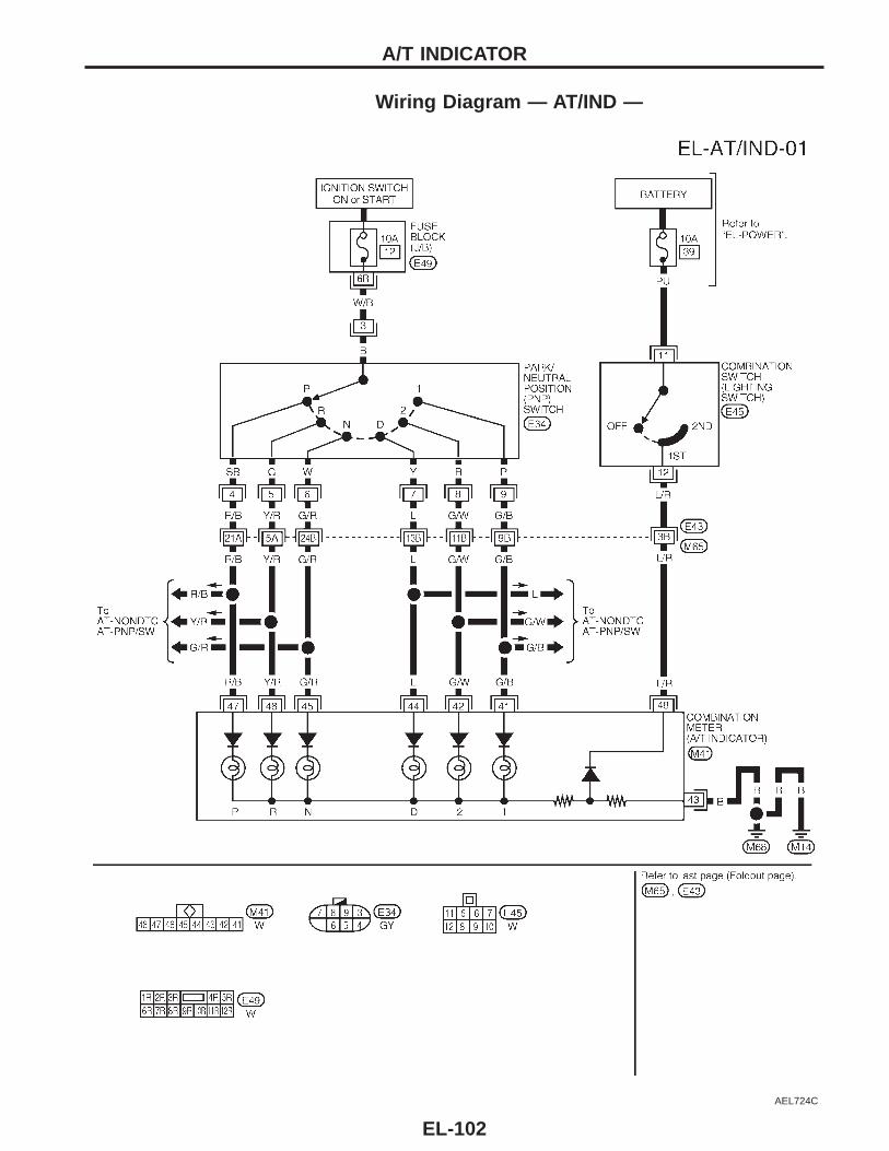
Wiring Diagram — AT/IND —
AEL724C
A/T INDICATOR
EL-102
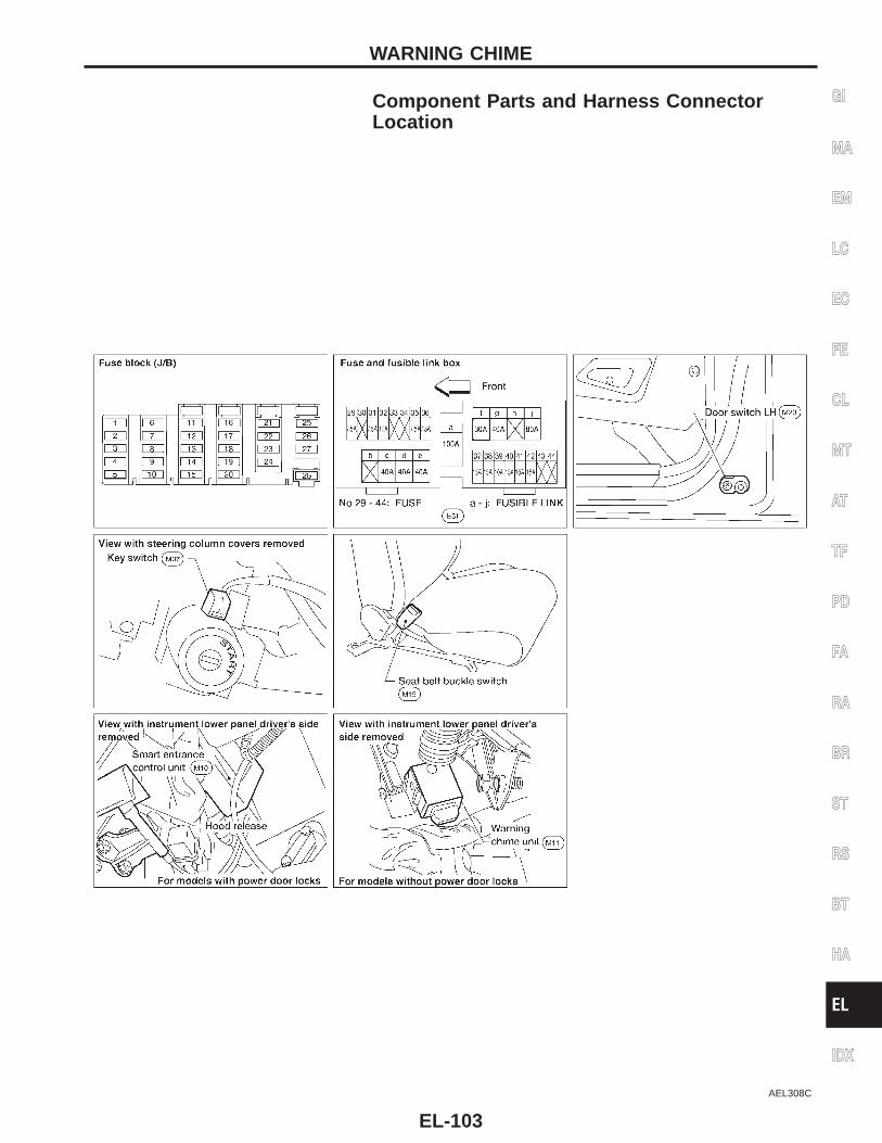
Component Parts and Harness ConnectorLocation
AEL308C
GI
MA
EM
LC
EC
FE
CL
MT
AT
TF
PD
FA
RA
BR
ST
RS
BT
HA
EL
IDX
WARNING CHIME
EL-103
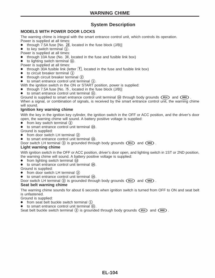
System DescriptionMODELS WITH POWER DOOR LOCKSThe warning chime is integral with the smart entrance control unit, which controls its operation.Power is supplied at all times:● through 7.5A fuse [No. , located in the fuse block (J/B)]● to key switch terminal s1 .Power is supplied at all times:● through 10A fuse (No. , located in the fuse and fusible link box)● to lighting switch terminal s11 .Power is supplied at all times:● through 30A fusible link (letter , located in the fuse and fusible link box)● to circuit breaker terminal s1● through circuit breaker terminal s2● to smart entrance control unit terminal s1 .With the ignition switch in the ON or START position, power is supplied:● through 7.5A fuse [No. , located in the fuse block (J/B)]● to smart entrance control unit terminal s11 .Ground is supplied to smart entrance control unit terminal s10 through body grounds sM14 and sM68 .When a signal, or combination of signals, is received by the smart entrance control unit, the warning chimewill sound.Ignition key warning chimeWith the key in the ignition key cylinder, the ignition switch in the OFF or ACC position, and the driver’s dooropen, the warning chime will sound. A battery positive voltage is supplied:● from key switch terminal s2● to smart entrance control unit terminal s24 .Ground is supplied:● from door switch LH terminal s2● to smart entrance control unit terminal s15 .Door switch LH terminal s3 is grounded through body grounds sM14 and sM68 .Light warning chimeWith ignition switch in the OFF or ACC position, driver’s door open, and lighting switch in 1ST or 2ND position,the warning chime will sound. A battery positive voltage is supplied:● from lighting switch terminal s12
● to smart entrance control unit terminal s25 .Ground is supplied:● from door switch LH terminal s2● to smart entrance control unit terminal s15 .Door switch LH terminal s3 is grounded through body grounds sM14 and sM68 .Seat belt warning chimeThe warning chime sounds for about 6 seconds when ignition switch is turned from OFF to ON and seat beltis unfastened.Ground is supplied:● from seat belt buckle switch terminal s1● to smart entrance control unit terminal s21 .Seat belt buckle switch terminal s2 is grounded through body grounds sM14 and sM68 .
WARNING CHIME
EL-104
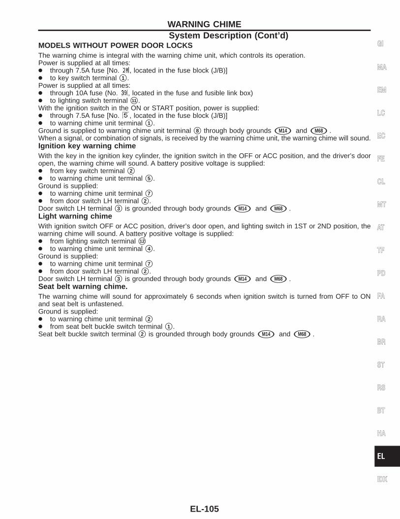
MODELS WITHOUT POWER DOOR LOCKSThe warning chime is integral with the warning chime unit, which controls its operation.Power is supplied at all times:● through 7.5A fuse [No. , located in the fuse block (J/B)]● to key switch terminal s1 .Power is supplied at all times:● through 10A fuse (No. , located in the fuse and fusible link box)● to lighting switch terminal s11 .With the ignition switch in the ON or START position, power is supplied:● through 7.5A fuse [No. , located in the fuse block (J/B)]● to warning chime unit terminal s1 .Ground is supplied to warning chime unit terminal s8 through body grounds sM14 and sM68 .When a signal, or combination of signals, is received by the warning chime unit, the warning chime will sound.Ignition key warning chimeWith the key in the ignition key cylinder, the ignition switch in the OFF or ACC position, and the driver’s dooropen, the warning chime will sound. A battery positive voltage is supplied:● from key switch terminal s2● to warning chime unit terminal s5 .Ground is supplied:● to warning chime unit terminal s7● from door switch LH terminal s2 .Door switch LH terminal s3 is grounded through body grounds sM14 and sM68 .Light warning chimeWith ignition switch OFF or ACC position, driver’s door open, and lighting switch in 1ST or 2ND position, thewarning chime will sound. A battery positive voltage is supplied:● from lighting switch terminal s12
● to warning chime unit terminal s4 .Ground is supplied:● to warning chime unit terminal s7● from door switch LH terminal s2 .Door switch LH terminal s3 is grounded through body grounds sM14 and sM68 .Seat belt warning chime.The warning chime will sound for approximately 6 seconds when ignition switch is turned from OFF to ONand seat belt is unfastened.Ground is supplied:● to warning chime unit terminal s2● from seat belt buckle switch terminal s1 .Seat belt buckle switch terminal s2 is grounded through body grounds sM14 and sM68 .
GI
MA
EM
LC
EC
FE
CL
MT
AT
TF
PD
FA
RA
BR
ST
RS
BT
HA
EL
IDX
WARNING CHIMESystem Description (Cont’d)
EL-105
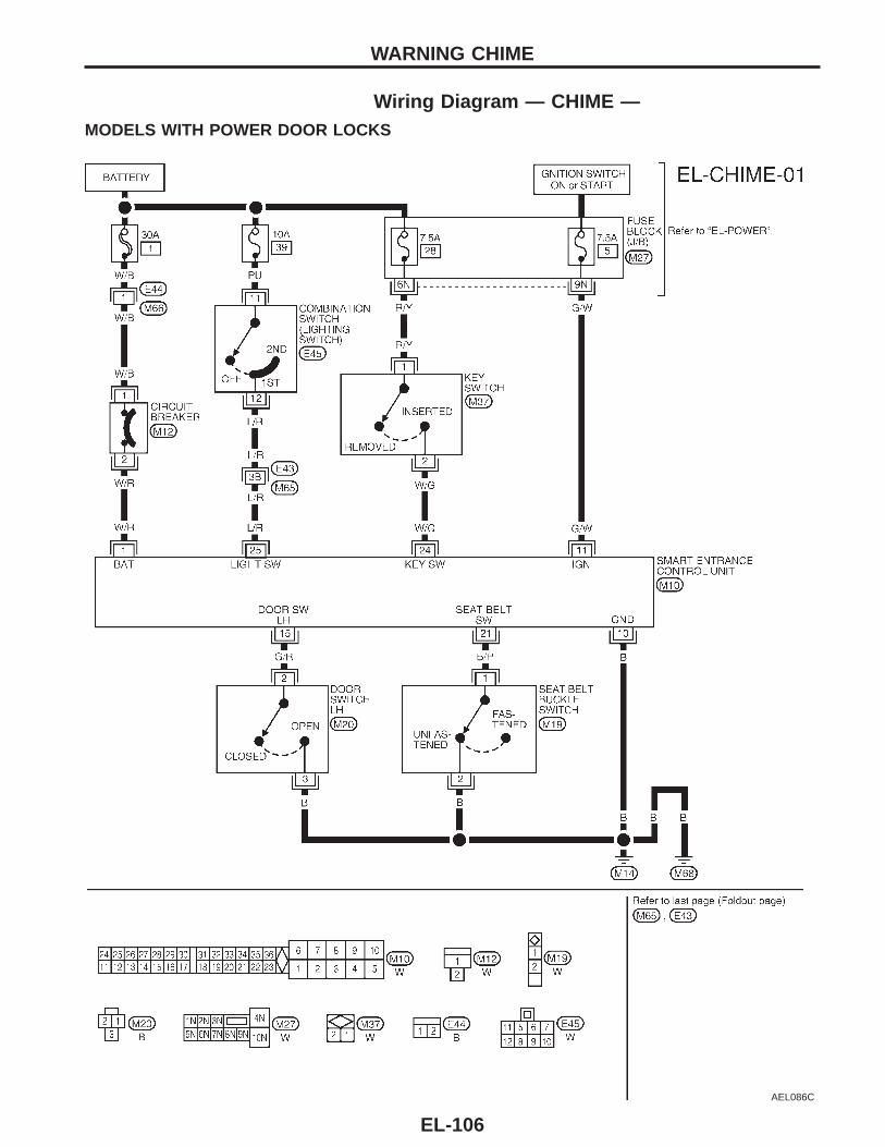
Wiring Diagram — CHIME —MODELS WITH POWER DOOR LOCKS
AEL086C
WARNING CHIME
EL-106
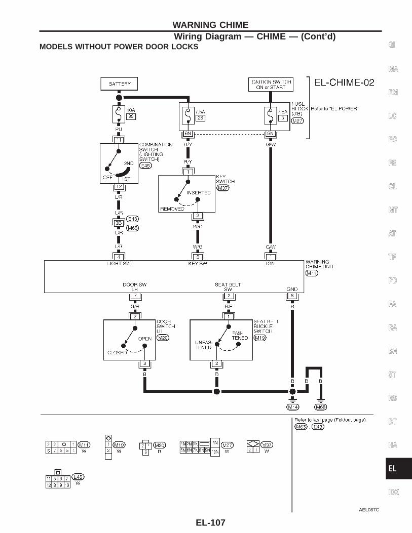
MODELS WITHOUT POWER DOOR LOCKS
AEL087C
GI
MA
EM
LC
EC
FE
CL
MT
AT
TF
PD
FA
RA
BR
ST
RS
BT
HA
EL
IDX
WARNING CHIMEWiring Diagram — CHIME — (Cont’d)
EL-107
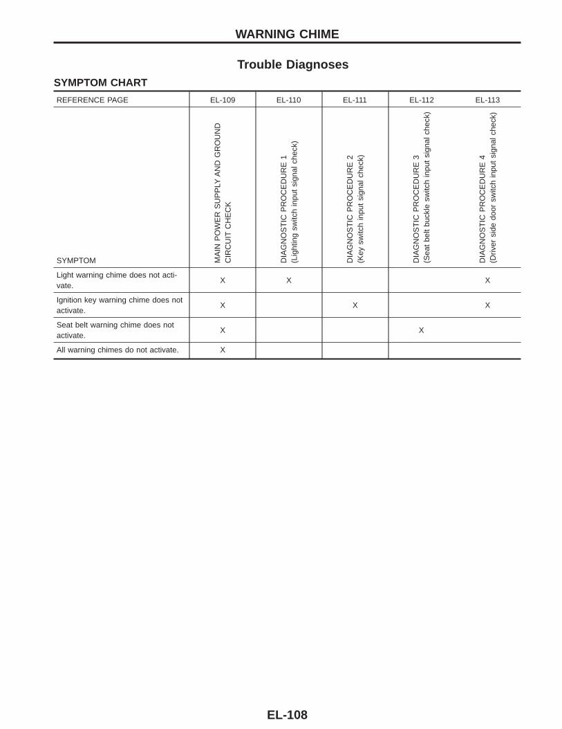
Trouble DiagnosesSYMPTOM CHART
REFERENCE PAGE EL-109 EL-110 EL-111 EL-112 EL-113
SYMPTOM MA
INP
OW
ER
SU
PP
LYA
ND
GR
OU
ND
CIR
CU
ITC
HE
CK
DIA
GN
OS
TIC
PR
OC
ED
UR
E1
(Lig
htin
gsw
itch
inpu
tsi
gnal
chec
k)
DIA
GN
OS
TIC
PR
OC
ED
UR
E2
(Key
switc
hin
put
sign
alch
eck)
DIA
GN
OS
TIC
PR
OC
ED
UR
E3
(Sea
tbe
ltbu
ckle
switc
hin
put
sign
alch
eck)
DIA
GN
OS
TIC
PR
OC
ED
UR
E4
(Driv
ersi
dedo
orsw
itch
inpu
tsi
gnal
chec
k)
Light warning chime does not acti-vate.
X X X
Ignition key warning chime does notactivate.
X X X
Seat belt warning chime does notactivate.
X X
All warning chimes do not activate. X
WARNING CHIME
EL-108
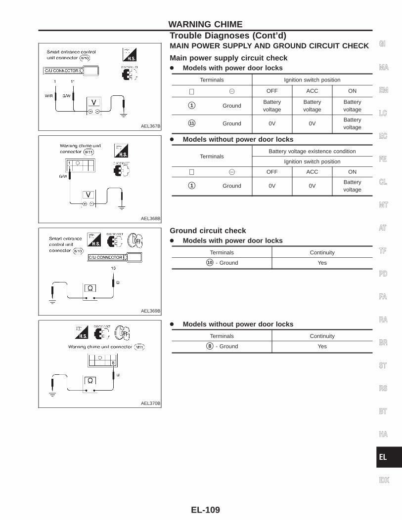
AEL367B
MAIN POWER SUPPLY AND GROUND CIRCUIT CHECK
Main power supply circuit check● Models with power door locks
Terminals Ignition switch position
⊕ @ OFF ACC ON
s1 GroundBatteryvoltage
Batteryvoltage
Batteryvoltage
s11 Ground 0V 0VBatteryvoltage
AEL368B
● Models without power door locks
TerminalsBattery voltage existence condition
Ignition switch position
⊕ @ OFF ACC ON
s1 Ground 0V 0VBatteryvoltage
AEL369B
Ground circuit check● Models with power door locks
Terminals Continuity
s10 - Ground Yes
AEL370B
● Models without power door locks
Terminals Continuity
s8 - Ground Yes
GI
MA
EM
LC
EC
FE
CL
MT
AT
TF
PD
FA
RA
BR
ST
RS
BT
HA
EL
IDX
WARNING CHIMETrouble Diagnoses (Cont’d)
EL-109
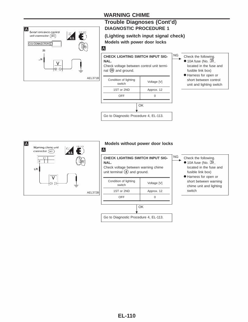
AEL371B
DIAGNOSTIC PROCEDURE 1
(Lighting switch input signal check)Models with power door locks
CHECK LIGHTING SWITCH INPUT SIG-NAL.Check voltage between control unit termi-nal s25 and ground.
OK
c
NG Check the following.● 10A fuse (No. ,
located in the fuse andfusible link box)
● Harness for open orshort between controlunit and lighting switch
Go to Diagnostic Procedure 4, EL-113.
AEL372B
Models without power door locks
CHECK LIGHTING SWITCH INPUT SIG-NAL.Check voltage between warning chimeunit terminal s4 and ground.
OK
c
NG Check the following.● 10A fuse (No. ,
located in the fuse andfusible link box)
● Harness for open orshort between warningchime unit and lightingswitch
Go to Diagnostic Procedure 4, EL-113.
Condition of lightingswitch
Voltage [V]
1ST or 2ND Approx. 12
OFF 0
Condition of lightingswitch
Voltage [V]
1ST or 2ND Approx. 12
OFF 0
WARNING CHIMETrouble Diagnoses (Cont’d)
.
.
EL-110
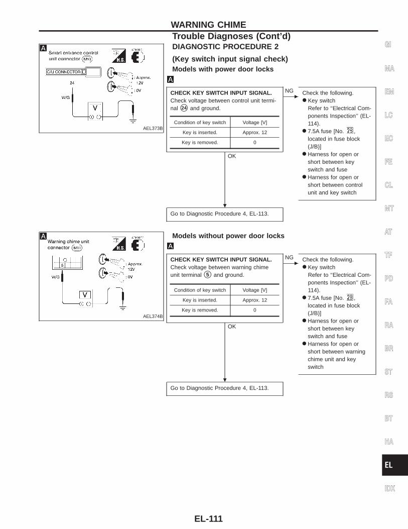
AEL373B
DIAGNOSTIC PROCEDURE 2
(Key switch input signal check)Models with power door locks
CHECK KEY SWITCH INPUT SIGNAL.Check voltage between control unit termi-nal s24 and ground.
OK
c
NG Check the following.● Key switch
Refer to ‘‘Electrical Com-ponents Inspection’’ (EL-114).
● 7.5A fuse [No. ,located in fuse block(J/B)]
● Harness for open orshort between keyswitch and fuse
● Harness for open orshort between controlunit and key switch
Go to Diagnostic Procedure 4, EL-113.
AEL374B
Models without power door locks
CHECK KEY SWITCH INPUT SIGNAL.Check voltage between warning chimeunit terminal s5 and ground.
OK
c
NG Check the following.● Key switch
Refer to ‘‘Electrical Com-ponents Inspection’’ (EL-114).
● 7.5A fuse [No. ,located in fuse block(J/B)]
● Harness for open orshort between keyswitch and fuse
● Harness for open orshort between warningchime unit and keyswitch
Go to Diagnostic Procedure 4, EL-113.
Condition of key switch Voltage [V]
Key is inserted. Approx. 12
Key is removed. 0
Condition of key switch Voltage [V]
Key is inserted. Approx. 12
Key is removed. 0
GI
MA
EM
LC
EC
FE
CL
MT
AT
TF
PD
FA
RA
BR
ST
RS
BT
HA
EL
IDX
WARNING CHIMETrouble Diagnoses (Cont’d)
.
.
EL-111
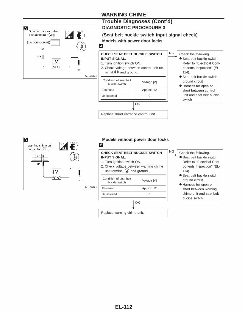
AEL375B
DIAGNOSTIC PROCEDURE 3
(Seat belt buckle switch input signal check)Models with power door locks
CHECK SEAT BELT BUCKLE SWITCHINPUT SIGNAL.1. Turn ignition switch ON.2. Check voltage between control unit ter-
minal s21 and ground.
OK
c
NG Check the following.● Seat belt buckle switch
Refer to ‘‘Electrical Com-ponents Inspection’’ (EL-114).
● Seat belt buckle switchground circuit
● Harness for open orshort between controlunit and seat belt buckleswitch
Replace smart entrance control unit.
AEL376B
Models without power door locks
CHECK SEAT BELT BUCKLE SWITCHINPUT SIGNAL.1. Turn ignition switch ON.2. Check voltage between warning chime
unit terminal s2 and ground.
OK
c
NG Check the following.● Seat belt buckle switch
Refer to ‘‘Electrical Com-ponents Inspection’’ (EL-114).
● Seat belt buckle switchground circuit
● Harness for open orshort between warningchime unit and seat beltbuckle switch
Replace warning chime unit.
Condition of seat beltbuckle switch
Voltage [V]
Fastened Approx. 12
Unfastened 0
Condition of seat beltbuckle switch
Voltage [V]
Fastened Approx. 12
Unfastened 0
WARNING CHIMETrouble Diagnoses (Cont’d)
.
.
EL-112
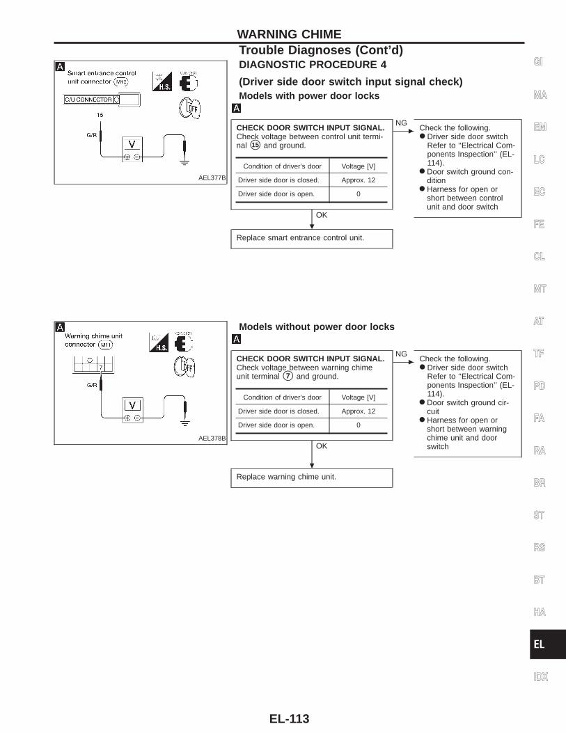
AEL377B
DIAGNOSTIC PROCEDURE 4
(Driver side door switch input signal check)Models with power door locks
CHECK DOOR SWITCH INPUT SIGNAL.Check voltage between control unit termi-nal s15 and ground.
OK
c
NGCheck the following.● Driver side door switch
Refer to ‘‘Electrical Com-ponents Inspection’’ (EL-114).
● Door switch ground con-dition
● Harness for open orshort between controlunit and door switch
Replace smart entrance control unit.
Condition of driver’s door Voltage [V]
Driver side door is closed. Approx. 12
Driver side door is open. 0
AEL378B
Models without power door locks
CHECK DOOR SWITCH INPUT SIGNAL.Check voltage between warning chimeunit terminal s7 and ground.
OK
c
NGCheck the following.● Driver side door switch
Refer to ‘‘Electrical Com-ponents Inspection’’ (EL-114).
● Door switch ground cir-cuit
● Harness for open orshort between warningchime unit and doorswitch
Replace warning chime unit.
Condition of driver’s door Voltage [V]
Driver side door is closed. Approx. 12
Driver side door is open. 0
GI
MA
EM
LC
EC
FE
CL
MT
AT
TF
PD
FA
RA
BR
ST
RS
BT
HA
EL
IDX
WARNING CHIMETrouble Diagnoses (Cont’d)
.
.
EL-113
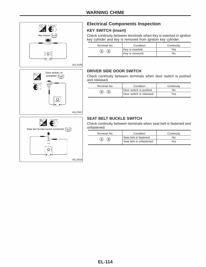
AEL416B
Electrical Components InspectionKEY SWITCH (insert)Check continuity between terminals when key is inserted in ignitionkey cylinder and key is removed from ignition key cylinder.
Terminal No. Condition Continuity
s1 - s2Key is inserted. YesKey is removed. No
AEL256C
DRIVER SIDE DOOR SWITCHCheck continuity between terminals when door switch is pushedand released.
Terminal No. Condition Continuity
s2 - s3Door switch is pushed. NoDoor switch is released. Yes
AEL381B
SEAT BELT BUCKLE SWITCHCheck continuity between terminals when seat belt is fastened andunfastened.
Terminal No. Condition Continuity
s1 - s2Seat belt is fastened. NoSeat belt is unfastened. Yes
WARNING CHIME
EL-114
System DescriptionWIPER OPERATIONThe wiper switch is controlled by a lever built into the combination switch.There are three wiper switch positions:● LO speed● HI speed● INT (Intermittent) (If equipped).With the ignition switch in the ON or START position, power is supplied:● through 20A fuse [No. , located in the fuse block (J/B)]● to wiper motor terminal sB and● to wiper amplifier terminal s6 (with intermittent wipers).Low and high speed wiper operationGround is supplied to wiper switch terminal s17 through body grounds sE12 and sE54 .When the wiper switch is placed in the LO position, ground is supplied:● through terminal s14 of the wiper switch● to wiper motor terminal sL .With power and ground supplied, the wiper motor operates at low speed.When the wiper switch is placed in the HI position, ground is supplied:● through terminal s16 of the wiper switch● to wiper motor terminal sH .With power and ground supplied, the wiper motor operates at high speed.Auto stop operationWith wiper switch turned OFF, wiper motor will continue to operate until wiper arms reach windshield base.When wiper arms are not located at base of windshield with wiper switch OFF, ground is supplied:● from terminal s14 of the wiper switch● to wiper motor terminal sL , in order to continue wiper motor operation at low speed.Ground is also supplied:● through terminal s13 of the wiper switch● to wiper amplifier terminal s4 (with intermittent wipers)● through terminal s8 of the wiper amplifier (with intermittent wipers)● to wiper motor terminal sP● through terminal sE of the wiper motor, and● through body grounds sE12 and sE54 .When wiper arms reach base of windshield, wiper motor terminals sP and sB are connected instead of ter-minals sP and sE . Wiper motor will then stop wiper arms at the PARK position.Intermittent operationThe wiper motor operates the wiper arms one time at low speed at a set interval of approximately 3 to 13seconds. This feature is controlled by the wiper amplifier.When the wiper switch is placed in the INT position, ground is supplied:● to wiper amplifier terminal s1● from wiper switch terminal s15
● through body grounds sE12 and sE54● to wiper motor terminal sL● through the wiper switch terminal s14
● to wiper switch terminal s13
● through wiper amplifier terminal s4● to wiper amplifier terminal s7● through body grounds sE12 and sE54 .The desired interval time is input:● to wiper amplifier terminal s2● from wiper switch terminal s19
● to wiper switch terminal s20
● through body grounds sE12 and sE54 .The wiper motor operates at low speed at the desired time interval.
GI
MA
EM
LC
EC
FE
CL
MT
AT
TF
PD
FA
RA
BR
ST
RS
BT
HA
EL
IDX
FRONT WIPER AND WASHER
EL-115
WASHER OPERATIONWith the ignition switch in the ON or START position, power is supplied:● through 20A fuse [No. , located in the fuse block (J/B)]● to washer motor terminal s+ .When the lever is pulled to the WASH position, ground is supplied:● to washer motor terminal s− , and● to wiper amplifier terminal s5 (with intermittent wipers)● from terminal s18 of the wiper switch● through terminal s17 of the wiper switch, and● through body grounds sE12 and sE54 .With power and ground supplied, the washer motor operates.When the lever is pulled to the WASH position for one second or more, the wiper motor operates at low speedfor approximately 3 seconds to clean windshield. This feature is controlled by the wiper amplifier in the samemanner as the intermittent operation on vehicles equipped with intermittent wipers.
FRONT WIPER AND WASHERSystem Description (Cont’d)
EL-116
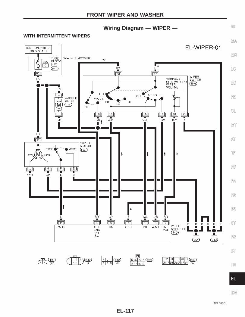
Wiring Diagram — WIPER —WITH INTERMITTENT WIPERS
AEL060C
GI
MA
EM
LC
EC
FE
CL
MT
AT
TF
PD
FA
RA
BR
ST
RS
BT
HA
EL
IDX
FRONT WIPER AND WASHER
EL-117
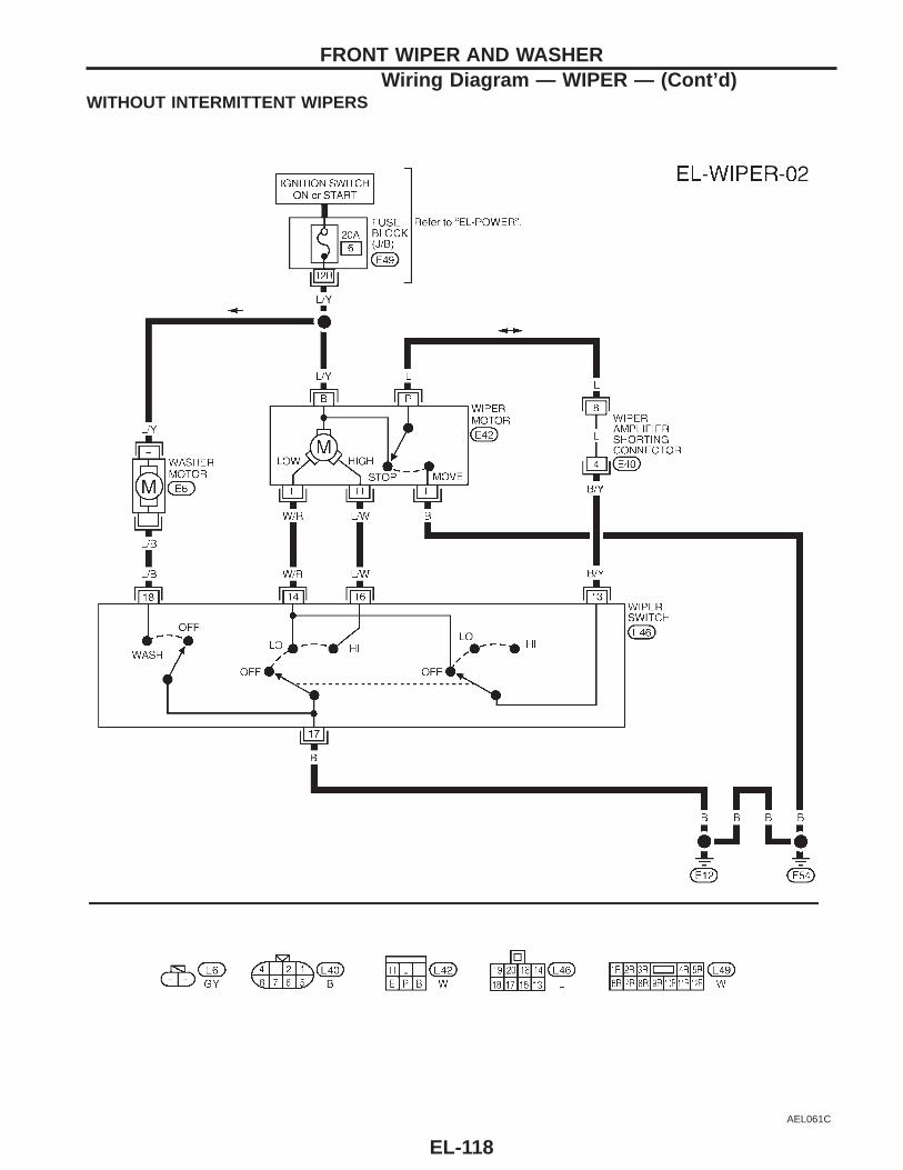
WITHOUT INTERMITTENT WIPERS
AEL061C
FRONT WIPER AND WASHERWiring Diagram — WIPER — (Cont’d)
EL-118
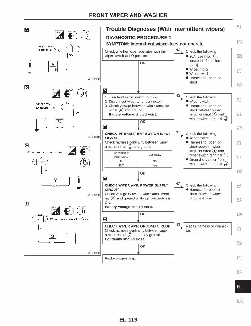
AEL390B
Trouble Diagnoses (With intermittent wipers)
DIAGNOSTIC PROCEDURE 1SYMPTOM: Intermittent wiper does not operate.
AEL391B
AEL392B
AEL393B
Check whether wiper operates with thewiper switch at LO position.
OK
c
NG Check the following.● 20A fuse [No. ,
located in fuse block(J/B)]
● Wiper motor● Wiper switch● Harness for open or
short
1. Turn front wiper switch to OFF.2. Disconnect wiper amp. connector.3. Check voltage between wiper amp. ter-
minal s4 and ground.Battery voltage should exist.
OK
c
NG Check the following.● Wiper switch● Harness for open or
short between wiperamp. terminal s4 andwiper switch terminal s13
CHECK INTERMITTENT SWITCH INPUTSIGNAL.Check harness continuity between wiperamp. terminal s1 and ground.
OK
c
NG Check the following.● Wiper switch● Harness for open or
short between wiperamp. terminal s1 andwiper switch terminal s15
● Ground circuit for frontwiper switch terminal s17
CHECK WIPER AMP. POWER SUPPLYCIRCUIT.Check voltage between wiper amp. termi-nal s6 and ground while ignition switch isON.Battery voltage should exist.
OK
c
NG Check the following.● Harness for open or
short between wiperamp. and fuse
CHECK WIPER AMP. GROUND CIRCUIT.Check harness continuity between wiperamp. terminal s7 and body ground.Continuity should exist.
OK
c
NG Repair harness or connec-tor.
Replace wiper amp.
Condition ofwiper switch
Continuity
OFF No
INT Yes
GI
MA
EM
LC
EC
FE
CL
MT
AT
TF
PD
FA
RA
BR
ST
RS
BT
HA
EL
IDX
FRONT WIPER AND WASHER
.
.
.
.
.
EL-119
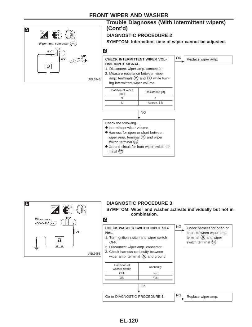
AEL394B
DIAGNOSTIC PROCEDURE 2SYMPTOM: Intermittent time of wiper cannot be adjusted.
CHECK INTERMITTENT WIPER VOL-UME INPUT SIGNAL.1. Disconnect wiper amp. connector.2. Measure resistance between wiper
amp. terminals s2 and s7 while turn-ing intermittent wiper volume.
NG
c
OK Replace wiper amp.
Check the following.● Intermittent wiper volume● Harness for open or short between
wiper amp. terminal s2 and wiperswitch terminal s19
● Ground circuit for front wiper switch ter-minal s20
AEL395B
DIAGNOSTIC PROCEDURE 3SYMPTOM: Wiper and washer activate individually but not in
combination.
CHECK WASHER SWITCH INPUT SIG-NAL.1. Turn ignition switch and wiper switch
OFF.2. Disconnect wiper amp. connector.3. Check harness continuity between
wiper amp. terminal s5 and ground.
OK
c
NG Check harness for open orshort between wiper amp.terminal s5 and wiperswitch terminal s18 .
Go to DIAGNOSTIC PROCEDURE 1.c
NG Replace wiper amp.
Position of wiperknob
Resistance [V]
S 0
L Approx. 1 k
Condition ofwasher switch
Continuity
OFF No
ON Yes
FRONT WIPER AND WASHERTrouble Diagnoses (With intermittent wipers)(Cont’d)
.
.
EL-120
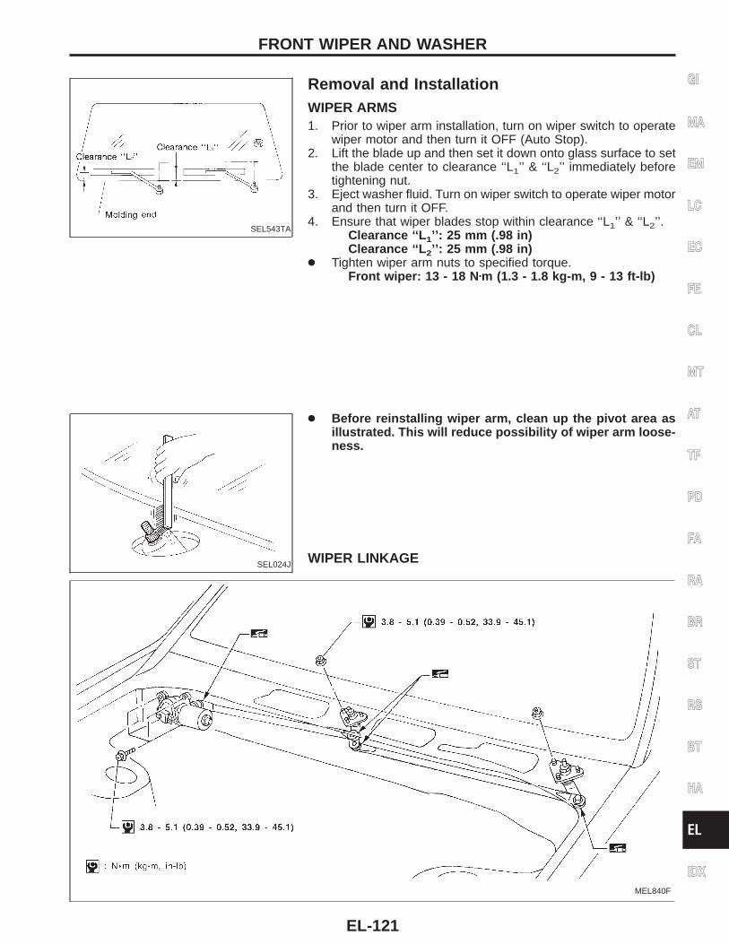
SEL543TA
Removal and InstallationWIPER ARMS1. Prior to wiper arm installation, turn on wiper switch to operate
wiper motor and then turn it OFF (Auto Stop).2. Lift the blade up and then set it down onto glass surface to set
the blade center to clearance ‘‘L1’’ & ‘‘L2’’ immediately beforetightening nut.
3. Eject washer fluid. Turn on wiper switch to operate wiper motorand then turn it OFF.
4. Ensure that wiper blades stop within clearance ‘‘L1’’ & ‘‘L2’’.Clearance ‘‘L 1’’: 25 mm (.98 in)Clearance ‘‘L 2’’: 25 mm (.98 in)
● Tighten wiper arm nuts to specified torque.Front wiper: 13 - 18 N zm (1.3 - 1.8 kg-m , 9 - 13 ft-lb)
SEL024J
● Before reinstalling wiper arm, clean up the pivot area asillustrated. This will reduce possibility of wiper arm loose-ness.
WIPER LINKAGE
MEL840F
GI
MA
EM
LC
EC
FE
CL
MT
AT
TF
PD
FA
RA
BR
ST
RS
BT
HA
EL
IDX
FRONT WIPER AND WASHER
EL-121
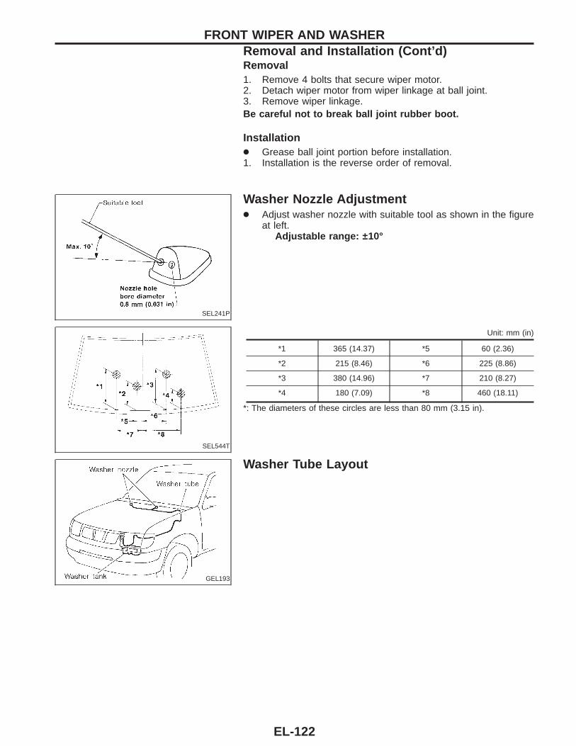
Removal1. Remove 4 bolts that secure wiper motor.2. Detach wiper motor from wiper linkage at ball joint.3. Remove wiper linkage.Be careful not to break ball joint rubber boot.
Installation● Grease ball joint portion before installation.1. Installation is the reverse order of removal.
SEL241P
Washer Nozzle Adjustment● Adjust washer nozzle with suitable tool as shown in the figure
at left.Adjustable range: ±10°
SEL544T
Unit: mm (in)
*1 365 (14.37) *5 60 (2.36)
*2 215 (8.46) *6 225 (8.86)
*3 380 (14.96) *7 210 (8.27)
*4 180 (7.09) *8 460 (18.11)
*: The diameters of these circles are less than 80 mm (3.15 in).
GEL193
Washer Tube Layout
FRONT WIPER AND WASHERRemoval and Installation (Cont’d)
EL-122
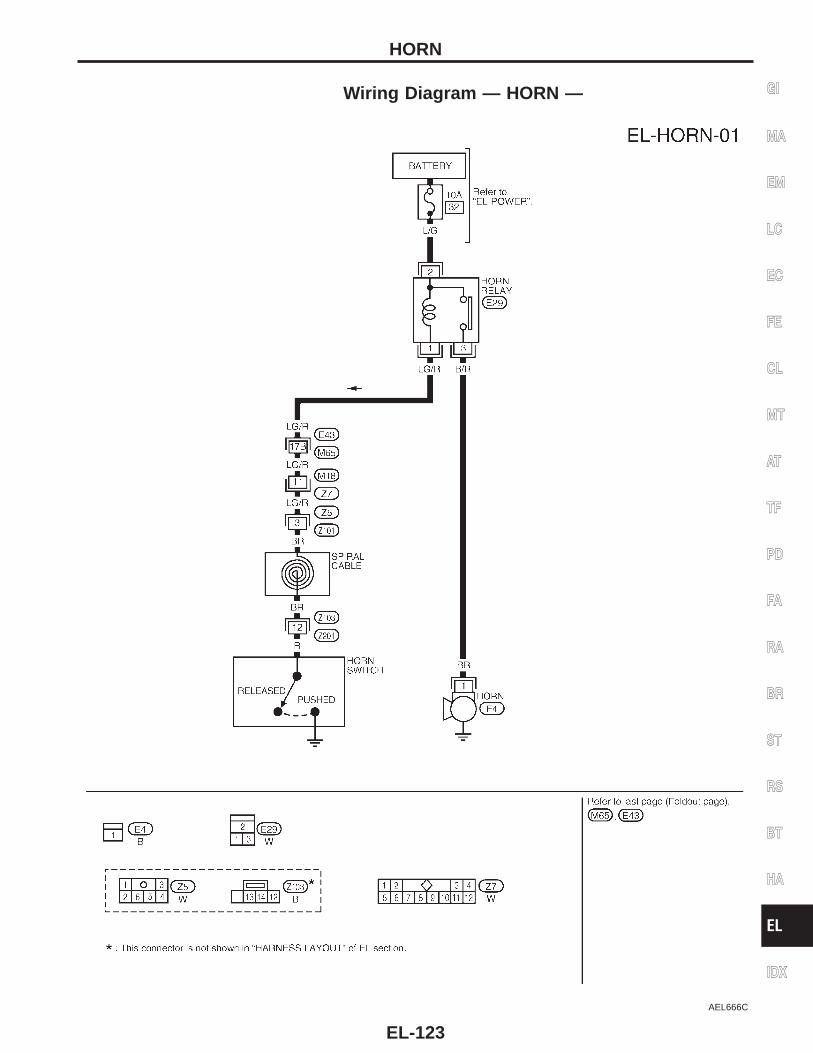
Wiring Diagram — HORN —
AEL666C
GI
MA
EM
LC
EC
FE
CL
MT
AT
TF
PD
FA
RA
BR
ST
RS
BT
HA
EL
IDX
HORN
EL-123
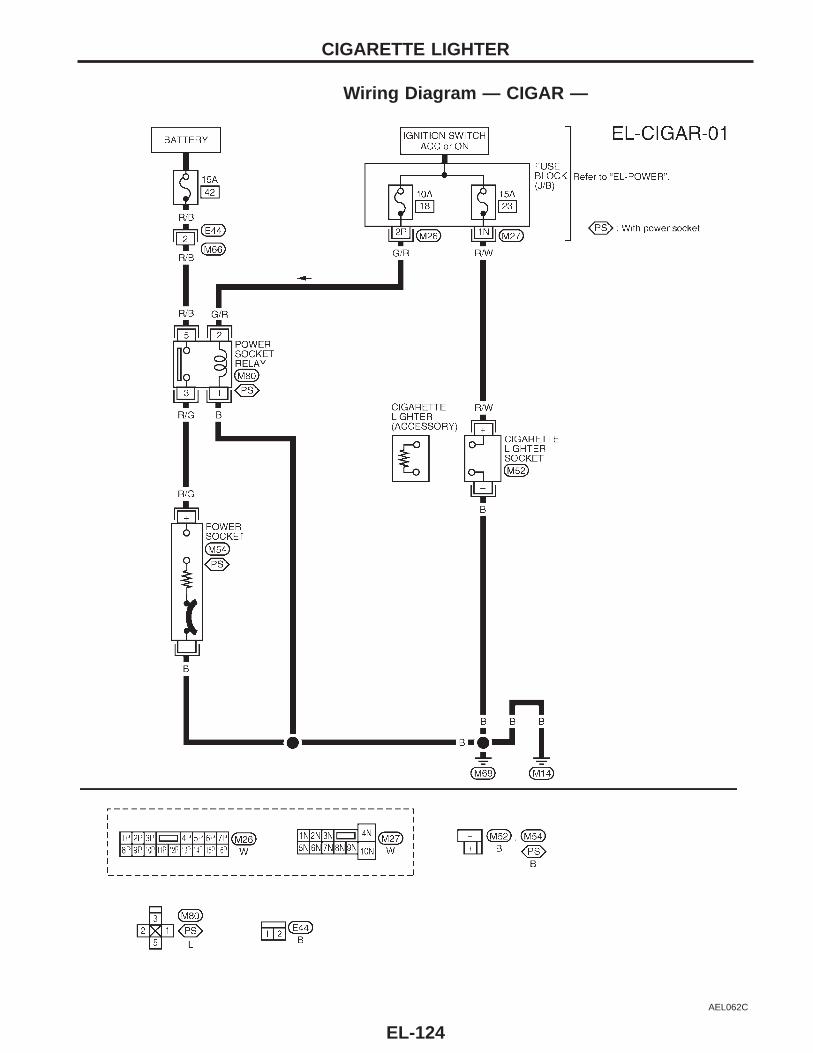
Wiring Diagram — CIGAR —
AEL062C
CIGARETTE LIGHTER
EL-124
System DescriptionRefer to Owners Manual for audio system operating instructions.
BASE AUDIO SYSTEMPower is supplied at all times:● through 15A fuse (No. , located in the fuse and fusible link box)● to audio unit terminal s6 .With the ignition switch in the ACC or ON position, power is supplied:● through 10A fuse [No. , located in the fuse block (J/B)]● to audio unit terminal s10 .Ground is supplied through the case of the audio unit.When the audio unit power knob is pushed to the ON position, audio signals are supplied:● through audio unit terminals s1 , s2 , s3 , s4 , s13 , s14 , s15 , and s16
● to the door speakers and tweeters.
PREMIUM AUDIO SYSTEMPower is supplied at all times:● through 15A fuse (No. , located in the fuse and fusible link box)● to audio unit terminal s6 and● to subwoofer amplifier terminal s8 .With the ignition switch in the ACC or ON position, power is supplied:● through 10A fuse [No. , located in the fuse block (J/B)]● to audio unit terminal s10 .Ground is supplied through the case of the audio unit.Ground is supplied to subwoofer amplifier terminal s7 through body grounds sM14 and sM68 .When the system is ON, an amplifier ON signal is sent:● through audio unit terminal s12
● to subwoofer amplifier terminal s6
and audio signals are supplied● through audio unit terminals s1 , s2 , s3 , s4 , s13 , s14 , s15 , and s16
● to the door speakers, tweeters, and subwoofer amplifier.
GI
MA
EM
LC
EC
FE
CL
MT
AT
TF
PD
FA
RA
BR
ST
RS
BT
HA
EL
IDX
AUDIO
EL-125
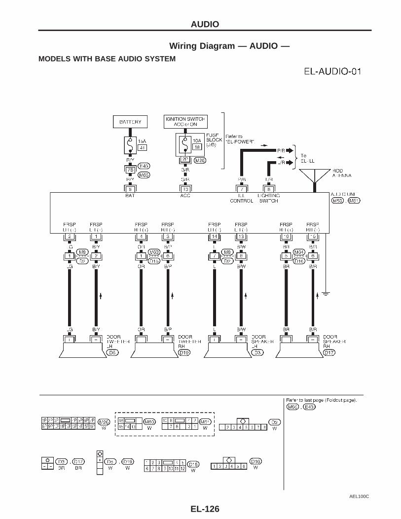
Wiring Diagram — AUDIO —MODELS WITH BASE AUDIO SYSTEM
AEL100C
AUDIO
EL-126
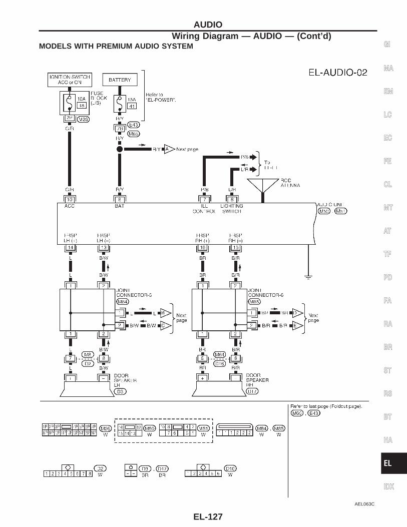
MODELS WITH PREMIUM AUDIO SYSTEM
AEL063C
GI
MA
EM
LC
EC
FE
CL
MT
AT
TF
PD
FA
RA
BR
ST
RS
BT
HA
EL
IDX
AUDIOWiring Diagram — AUDIO — (Cont’d)
EL-127
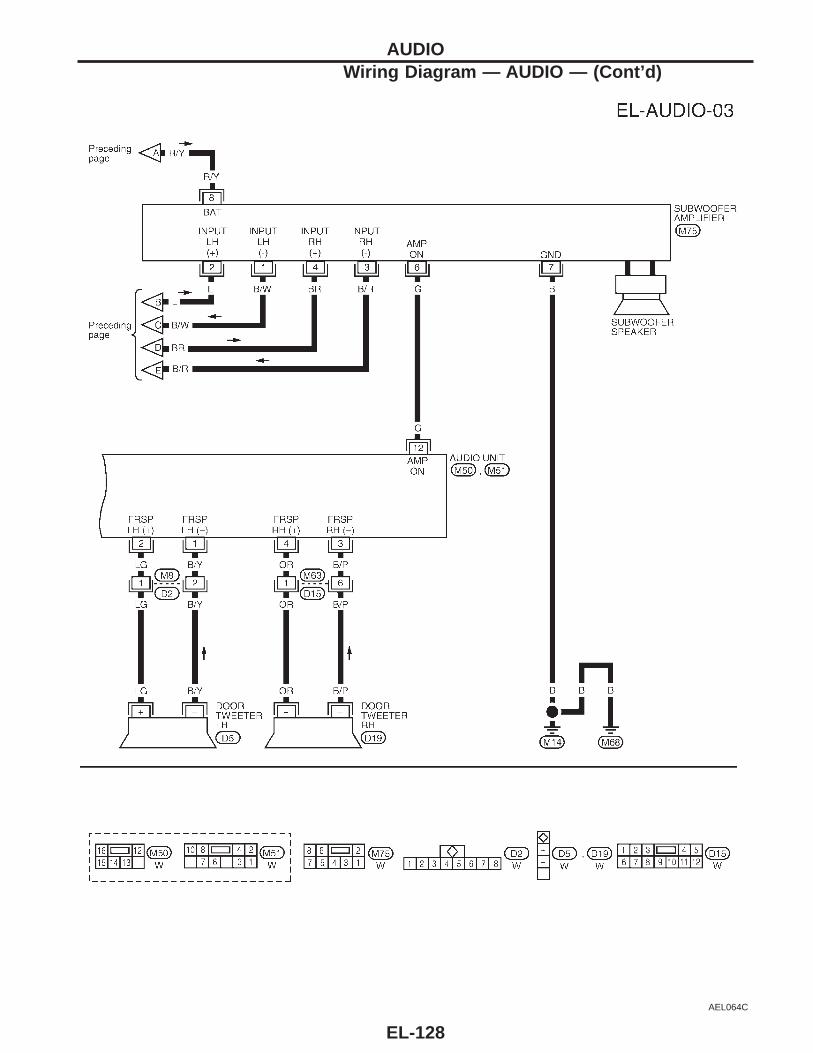
AEL064C
AUDIOWiring Diagram — AUDIO — (Cont’d)
EL-128
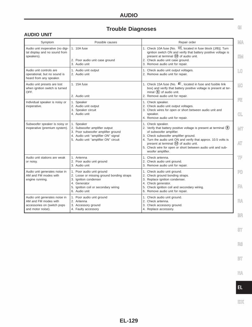
Trouble DiagnosesAUDIO UNIT
Symptom Possible causes Repair order
Audio unit inoperative (no digi-tal display and no sound fromspeakers).
1. 10A fuse
2. Poor audio unit case ground3. Audio unit
1. Check 10A fuse [No. , located in fuse block (J/B)]. Turnignition switch ON and verify that battery positive voltage ispresent at terminal s10 of audio unit.
2. Check audio unit case ground.3. Remove audio unit for repair.
Audio unit controls areoperational, but no sound isheard from any speaker.
1. Audio unit output2. Audio unit
1. Check audio unit output voltages.2. Remove audio unit for repair.
Audio unit presets are lostwhen ignition switch is turnedOFF.
1. 15A fuse
2. Audio unit
1. Check 15A fuse (No. , located in fuse and fusible linkbox) and verify that battery positive voltage is present at ter-minal s6 of audio unit.
2. Remove audio unit for repair.
Individual speaker is noisy orinoperative.
1. Speaker2. Audio unit output3. Speaker circuit4. Audio unit
1. Check speaker.2. Check audio unit output voltages.3. Check wires for open or short between audio unit and
speaker.4. Remove audio unit for repair.
Subwoofer speaker is noisy orinoperative (premium system).
1. Speaker2. Subwoofer amplifier output3. Poor subwoofer amplifier ground4. Audio unit ‘‘amplifier ON’’ signal5. Audio unit ‘‘amplifier ON’’ circuit
1. Check speaker.2. Verify that battery positive voltage is present at terminal s8
of subwoofer amplifier.3. Check subwoofer amplifier ground.4. Turn the audio unit ON and verify that approx. 10.5 volts is
present at terminal s12 of audio unit.5. Check wire for open or short between audio unit and sub-
woofer amplifier.
Audio unit stations are weakor noisy.
1. Antenna2. Poor audio unit ground3. Audio unit
1. Check antenna.2. Check audio unit ground.3. Remove audio unit for repair.
Audio unit generates noise inAM and FM modes withengine running.
1. Poor audio unit ground2. Loose or missing ground bonding straps3. Ignition condenser4. Generator5. Ignition coil or secondary wiring6. Audio unit
1. Check audio unit ground.2. Check ground bonding straps.3. Replace ignition condenser.4. Check generator.5. Check ignition coil and secondary wiring.6. Remove audio unit for repair.
Audio unit generates noise inAM and FM modes withaccessories on (switch popsand motor noise).
1. Poor audio unit ground2. Antenna3. Accessory ground4. Faulty accessory
1. Check audio unit ground.2. Check antenna.3. Check accessory ground.4. Replace accessory.
GI
MA
EM
LC
EC
FE
CL
MT
AT
TF
PD
FA
RA
BR
ST
RS
BT
HA
EL
IDX
AUDIO
EL-129
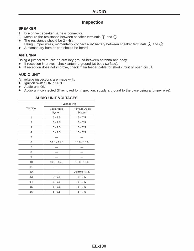
InspectionSPEAKER1. Disconnect speaker harness connector.2. Measure the resistance between speaker terminals s+ and s− .● The resistance should be 2 - 4V.3. Using jumper wires, momentarily connect a 9V battery between speaker terminals s+ and s− .● A momentary hum or pop should be heard.
ANTENNAUsing a jumper wire, clip an auxiliary ground between antenna and body.● If reception improves, check antenna ground (at body surface).● If reception does not improve, check main feeder cable for short circuit or open circuit.
AUDIO UNITAll voltage inspections are made with:● Ignition switch ON or ACC● Audio unit ON● Audio unit connected (If removed for inspection, supply a ground to the case using a jumper wire).
AUDIO UNIT VOLTAGES
Terminal
Voltage (V)
Base AudioSystem
Premium AudioSystem
1 5 - 7.5 5 - 7.5
2 5 - 7.5 5 - 7.5
3 5 - 7.5 5 - 7.5
4 5 - 7.5 5 - 7.5
5 — —
6 10.8 - 15.6 10.8 - 15.6
7 — —
8 — —
9 — —
10 10.8 - 15.6 10.8 - 15.6
11 — —
12 — Approx. 10.5
13 5 - 7.5 5 - 7.5
14 5 - 7.5 5 - 7.5
15 5 - 7.5 5 - 7.5
16 5 - 7.5 5 - 7.5
AUDIO
EL-130
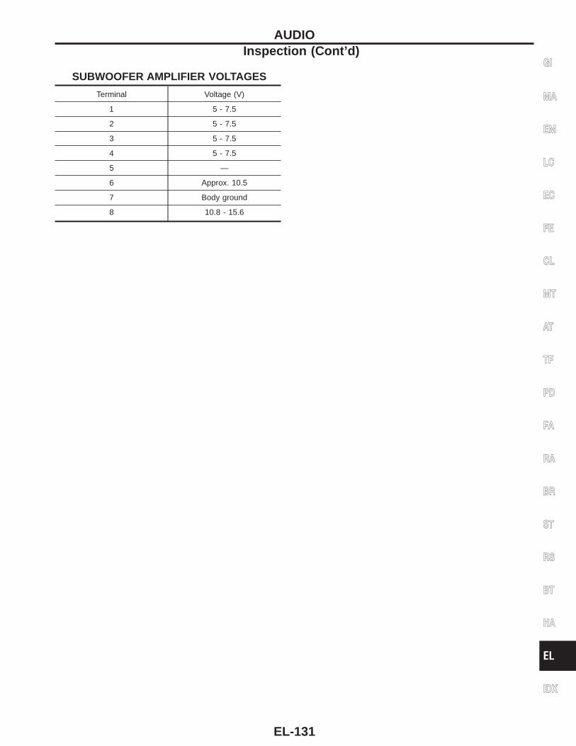
SUBWOOFER AMPLIFIER VOLTAGES
Terminal Voltage (V)
1 5 - 7.5
2 5 - 7.5
3 5 - 7.5
4 5 - 7.5
5 —
6 Approx. 10.5
7 Body ground
8 10.8 - 15.6
GI
MA
EM
LC
EC
FE
CL
MT
AT
TF
PD
FA
RA
BR
ST
RS
BT
HA
EL
IDX
AUDIOInspection (Cont’d)
EL-131
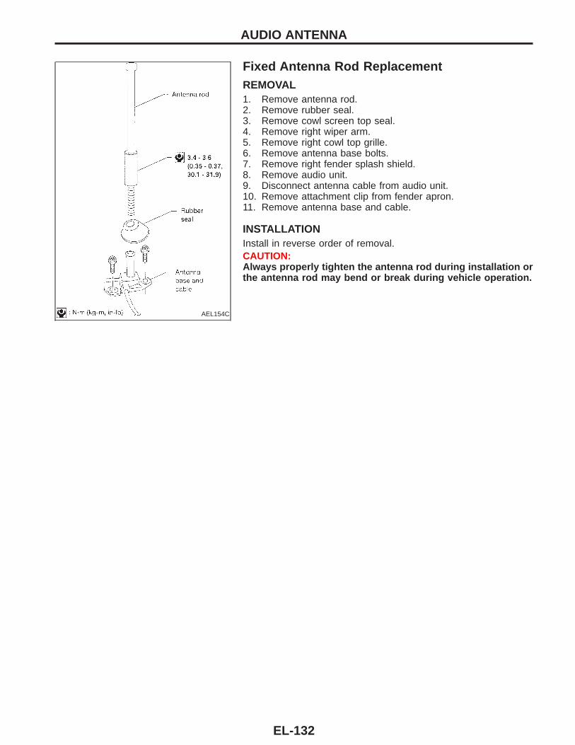
AEL154C
Fixed Antenna Rod ReplacementREMOVAL1. Remove antenna rod.2. Remove rubber seal.3. Remove cowl screen top seal.4. Remove right wiper arm.5. Remove right cowl top grille.6. Remove antenna base bolts.7. Remove right fender splash shield.8. Remove audio unit.9. Disconnect antenna cable from audio unit.10. Remove attachment clip from fender apron.11. Remove antenna base and cable.
INSTALLATIONInstall in reverse order of removal.CAUTION:Always properly tighten the antenna rod during installation orthe antenna rod may bend or break during vehicle operation.
AUDIO ANTENNA
EL-132
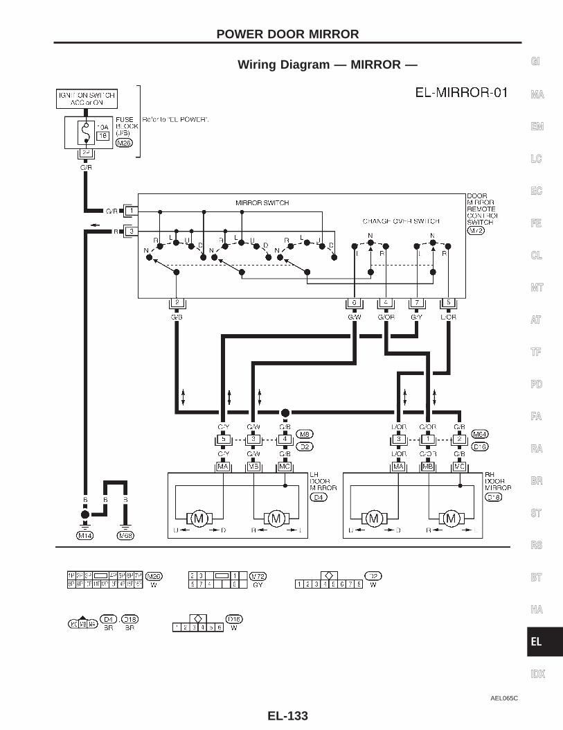
Wiring Diagram — MIRROR —
AEL065C
GI
MA
EM
LC
EC
FE
CL
MT
AT
TF
PD
FA
RA
BR
ST
RS
BT
HA
EL
IDX
POWER DOOR MIRROR
EL-133
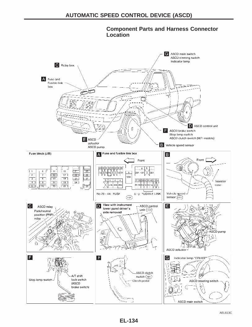
Component Parts and Harness ConnectorLocation
AEL613C
AUTOMATIC SPEED CONTROL DEVICE (ASCD)
EL-134
System DescriptionRefer to Owner’s Manual for ASCD operating instructions.When the ignition switch is in the ON or START position, power is supplied:● through 7.5A fuse [No. , located in the fuse block (J/B)]● to ASCD main switch terminal s1● to ASCD hold relay terminal s5● to ASCD brake switch terminal s1● through ASCD brake switch terminal s2● to ASCD hold relay terminal s7 .When ASCD main switch is in the ON position, power is supplied:● from ASCD main switch terminal s3● to ASCD hold relay terminal s2 .Ground is supplied:● to ASCD hold relay terminal s1● through body grounds sM14 and sM68 .With power and ground supplied, ASCD hold relay is energized, and then power is supplied:● from ASCD hold relay terminal s3● to ASCD control unit terminal s4 and● to ASCD main switch terminal s2 .After the ASCD main switch is released, power remains supplied:● to the coil circuit of ASCD hold relay● through ASCD main switch terminal s3 .This power supply is kept until one of following conditions exists:● Ignition switch is returned to the ACC or OFF position● ASCD main switch is pushed to OFF position.When ASCD hold relay is energized, power is also supplied to ASCD control unit terminal s5 :● through ASCD brake switch and● ASCD clutch switch (with M/T) or● ASCD relay (with A/T).Ground is supplied:● to ASCD control unit terminal s3● through body grounds sM14 and sM68 .
INPUTSAt this point, the system is ready to activate or deactivate, based on inputs from the following:● speedometer in the combination meter● stop lamp switch● ASCD steering switch● ASCD clutch switch (with M/T) or● ASCD relay (with A/T)● ASCD brake switch.A vehicle speed input is supplied:● to ASCD control unit terminal s7● from terminal s34 of the combination meter.Power is supplied at all times:● to stop lamp switch terminal s1● through 10A fuse [No. , located in the fuse block (J/B)].When the brake pedal is depressed, power is supplied:● from terminal s2 of the stop lamp switch● to ASCD control unit terminal s11 .Power is supplied at all times:● through 10A fuse [No. , located in the fuse and fusible link box]● to horn relay terminal s2● through terminal s1 of the horn relay● to ASCD steering switch terminal s3 .When the SET/COAST switch is depressed, power is supplied:● from terminal s2 of the ASCD steering switch● to ASCD control unit terminal s2 .
GI
MA
EM
LC
EC
FE
CL
MT
AT
TF
PD
FA
RA
BR
ST
RS
BT
HA
EL
IDX
AUTOMATIC SPEED CONTROL DEVICE (ASCD)
EL-135
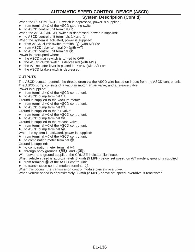
When the RESUME/ACCEL switch is depressed, power is supplied:● from terminal s1 of the ASCD steering switch● to ASCD control unit terminal s1 .When the ASCD CANCEL switch is depressed, power is supplied:● to ASCD control unit terminals s1 and s2 .When the system is activated, power is supplied:● from ASCD clutch switch terminal s2 (with M/T) or● from ASCD relay terminal s4 (with A/T)● to ASCD control unit terminal s5 .Power is interrupted when:● the ASCD main switch is turned to OFF● the ASCD clutch switch is depressed (with M/T)● the A/T selector lever is placed in P or N (with A/T) or● the ASCD brake switch is depressed.
OUTPUTSThe ASCD actuator controls the throttle drum via the ASCD wire based on inputs from the ASCD control unit.The ASCD pump consists of a vacuum motor, an air valve, and a release valve.Power is supplied:● from terminal s8 of the ASCD control unit● to ASCD pump terminal s1 .Ground is supplied to the vacuum motor:● from terminal s9 of the ASCD control unit● to ASCD pump terminal s2 .Ground is supplied to the air valve:● from terminal s10 of the ASCD control unit● to ASCD pump terminal s3 .Ground is supplied to the release valve:● from terminal s14 of the ASCD control unit● to ASCD pump terminal s4 .When the system is activated, power is supplied:● from terminal s13 of the ASCD control unit● to combination meter terminal s30 .Ground is supplied:● to combination meter terminal s33
● through body grounds sM14 and sM68 .With power and ground supplied, the CRUISE indicator illuminates.When vehicle speed is approximately 8 km/h (5 MPH) below set speed on A/T models, ground is supplied:● from terminal s12 of the ASCD control unit● to transmission control module terminal s24 .When this occurs, the transmission control module cancels overdrive.When vehicle speed is approximately 3 km/h (2 MPH) above set speed, overdrive is reactivated.
AUTOMATIC SPEED CONTROL DEVICE (ASCD)System Description (Cont’d)
EL-136
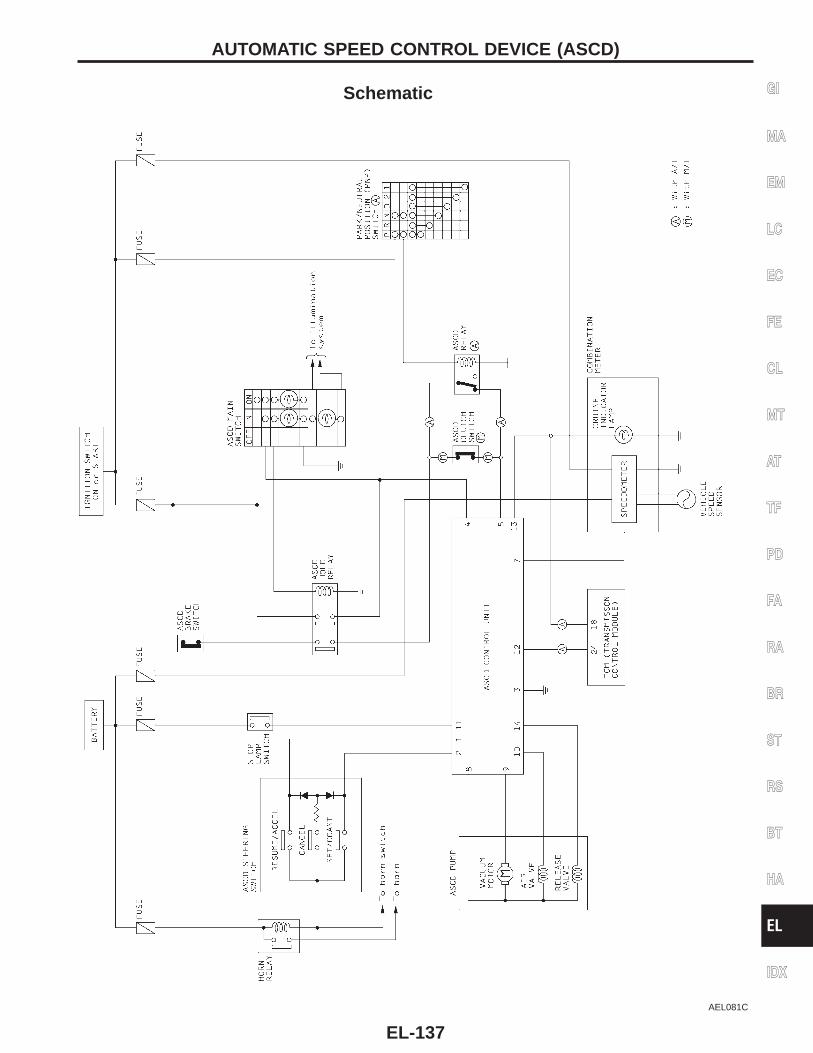
Schematic
AEL081C
GI
MA
EM
LC
EC
FE
CL
MT
AT
TF
PD
FA
RA
BR
ST
RS
BT
HA
EL
IDX
AUTOMATIC SPEED CONTROL DEVICE (ASCD)
EL-137
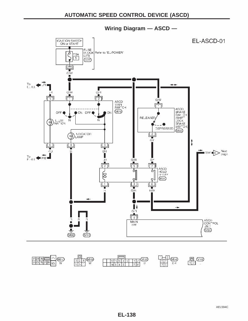
Wiring Diagram — ASCD —
AEL594C
AUTOMATIC SPEED CONTROL DEVICE (ASCD)
EL-138
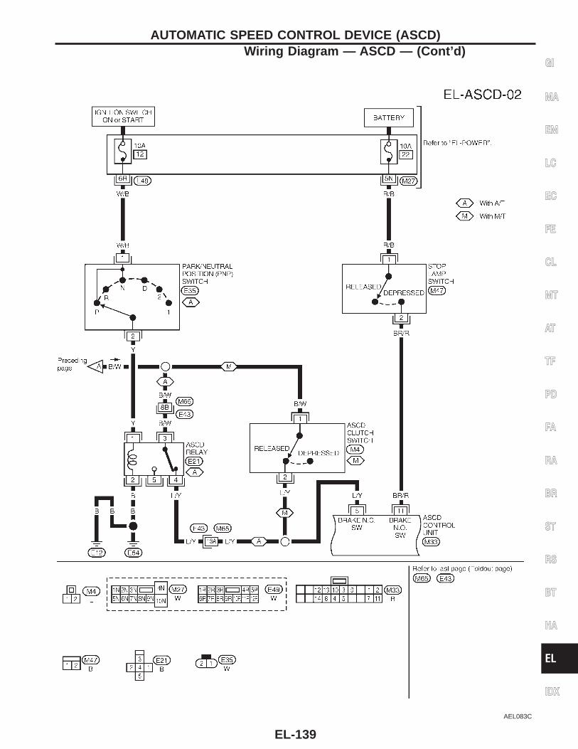
AEL083C
GI
MA
EM
LC
EC
FE
CL
MT
AT
TF
PD
FA
RA
BR
ST
RS
BT
HA
EL
IDX
AUTOMATIC SPEED CONTROL DEVICE (ASCD)Wiring Diagram — ASCD — (Cont’d)
EL-139
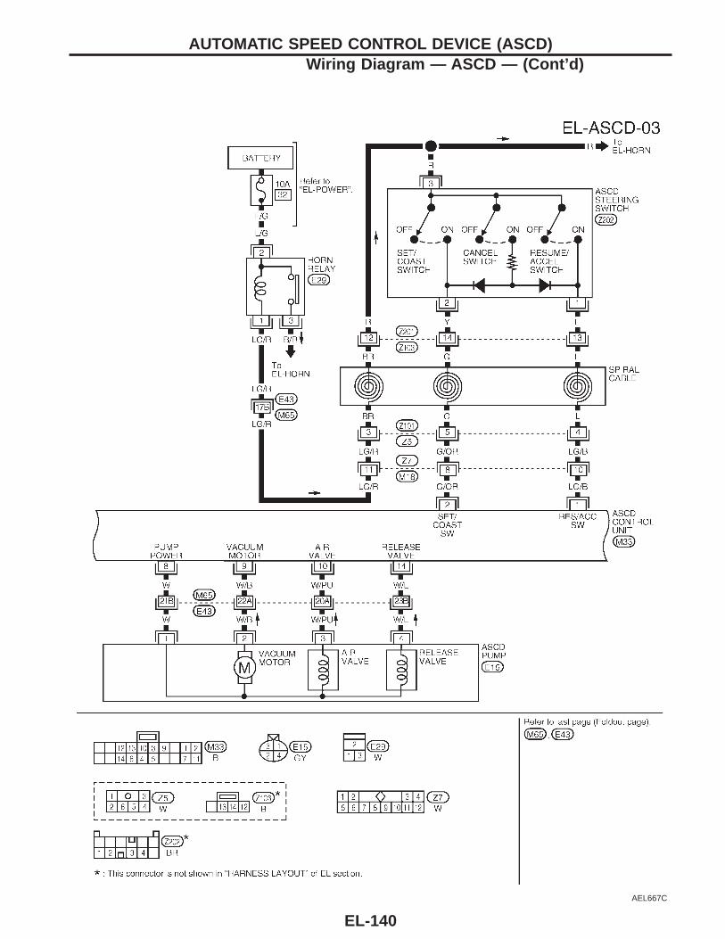
AEL667C
AUTOMATIC SPEED CONTROL DEVICE (ASCD)Wiring Diagram — ASCD — (Cont’d)
EL-140
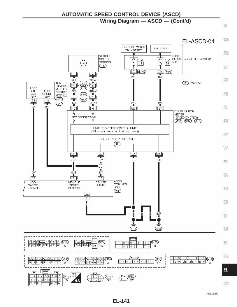
AEL085C
GI
MA
EM
LC
EC
FE
CL
MT
AT
TF
PD
FA
RA
BR
ST
RS
BT
HA
EL
IDX
AUTOMATIC SPEED CONTROL DEVICE (ASCD)Wiring Diagram — ASCD — (Cont’d)
EL-141
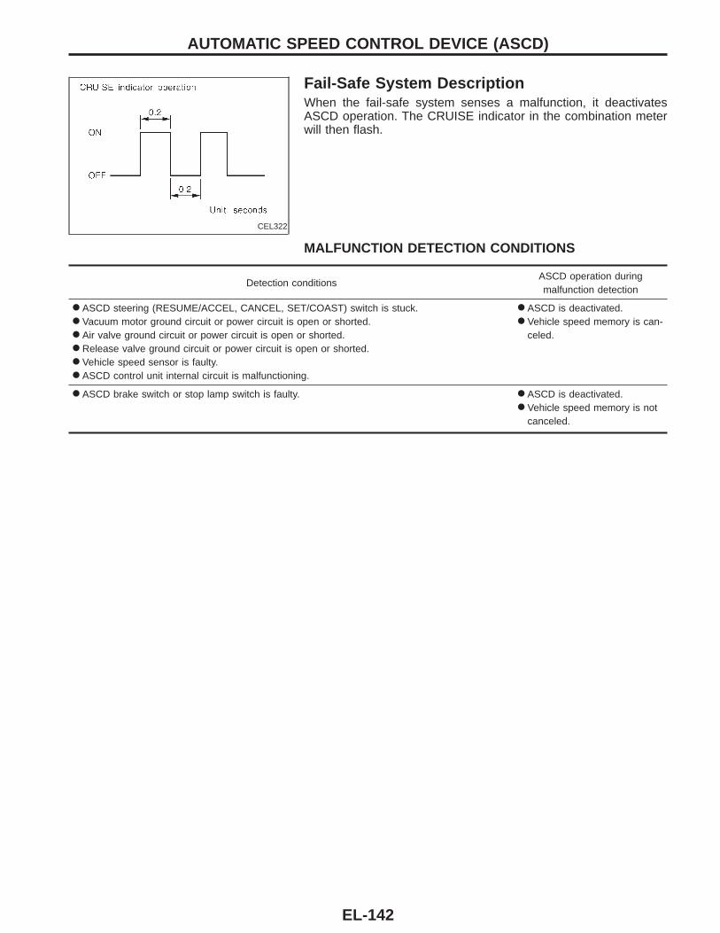
CEL322
Fail-Safe System DescriptionWhen the fail-safe system senses a malfunction, it deactivatesASCD operation. The CRUISE indicator in the combination meterwill then flash.
MALFUNCTION DETECTION CONDITIONS
Detection conditionsASCD operation duringmalfunction detection
● ASCD steering (RESUME/ACCEL, CANCEL, SET/COAST) switch is stuck.● Vacuum motor ground circuit or power circuit is open or shorted.● Air valve ground circuit or power circuit is open or shorted.● Release valve ground circuit or power circuit is open or shorted.● Vehicle speed sensor is faulty.● ASCD control unit internal circuit is malfunctioning.
● ASCD is deactivated.● Vehicle speed memory is can-
celed.
● ASCD brake switch or stop lamp switch is faulty. ● ASCD is deactivated.● Vehicle speed memory is not
canceled.
AUTOMATIC SPEED CONTROL DEVICE (ASCD)
EL-142
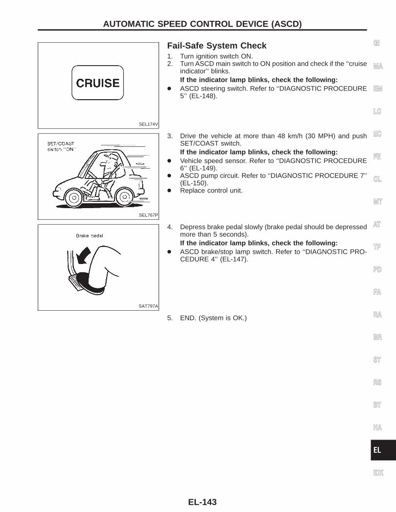
SEL174V
Fail-Safe System Check1. Turn ignition switch ON.2. Turn ASCD main switch to ON position and check if the ‘‘cruise
indicator’’ blinks.If the indicator lamp blinks, check the following:
● ASCD steering switch. Refer to ‘‘DIAGNOSTIC PROCEDURE5’’ (EL-148).
SEL767P
3. Drive the vehicle at more than 48 km/h (30 MPH) and pushSET/COAST switch.If the indicator lamp blinks, check the following:
● Vehicle speed sensor. Refer to ‘‘DIAGNOSTIC PROCEDURE6’’ (EL-149).
● ASCD pump circuit. Refer to ‘‘DIAGNOSTIC PROCEDURE 7’’(EL-150).
● Replace control unit.
SAT797A
4. Depress brake pedal slowly (brake pedal should be depressedmore than 5 seconds).If the indicator lamp blinks, check the following:
● ASCD brake/stop lamp switch. Refer to ‘‘DIAGNOSTIC PRO-CEDURE 4’’ (EL-147).
5. END. (System is OK.)
GI
MA
EM
LC
EC
FE
CL
MT
AT
TF
PD
FA
RA
BR
ST
RS
BT
HA
EL
IDX
AUTOMATIC SPEED CONTROL DEVICE (ASCD)
EL-143
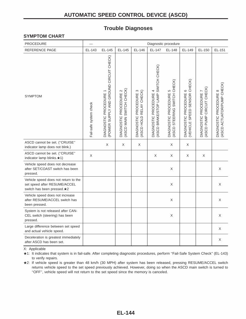
Trouble DiagnosesSYMPTOM CHART
PROCEDURE — Diagnostic procedure
REFERENCE PAGE EL-143 EL-145 EL-145 EL-146 EL-147 EL-148 EL-149 EL-150 EL-151
SYMPTOM
Fai
l-saf
esy
stem
chec
k
DIA
GN
OS
TIC
PR
OC
ED
UR
E1
(PO
WE
RS
UP
PLY
AN
DG
RO
UN
DC
IRC
UIT
CH
EC
K)
DIA
GN
OS
TIC
PR
OC
ED
UR
E2
(AS
CD
MA
INS
WIT
CH
CH
EC
K)
DIA
GN
OS
TIC
PR
OC
ED
UR
E3
(AS
CD
HO
LDR
ELA
YC
HE
CK
)
DIA
GN
OS
TIC
PR
OC
ED
UR
E4
(AS
CD
BR
AK
E/S
TO
PLA
MP
SW
ITC
HC
HE
CK
)
DIA
GN
OS
TIC
PR
OC
ED
UR
E5
(AS
CD
ST
EE
RIN
GS
WIT
CH
CH
EC
K)
DIA
GN
OS
TIC
PR
OC
ED
UR
E6
(VE
HIC
LES
PE
ED
SE
NS
OR
CH
EC
K)
DIA
GN
OS
TIC
PR
OC
ED
UR
E7
(AS
CD
PU
MP
CIR
CU
ITC
HE
CK
)
DIA
GN
OS
TIC
PR
OC
ED
UR
E8
(AS
CD
AC
TU
AT
OR
/PU
MP
CH
EC
K)
ASCD cannot be set. (‘‘CRUISE’’indicator lamp does not blink.)
X X X X X
ASCD cannot be set. (‘‘CRUISE’’indicator lamp blinks..1)
X X X X X
Vehicle speed does not decreaseafter SET/COAST switch has beenpressed.
X X
Vehicle speed does not return to theset speed after RESUME/ACCELswitch has been pressed..2
X X
Vehicle speed does not increaseafter RESUME/ACCEL switch hasbeen pressed.
X X
System is not released after CAN-CEL switch (steering) has beenpressed.
X X
Large difference between set speedand actual vehicle speed.
X
Deceleration is greatest immediatelyafter ASCD has been set.
X
X: Applicable.1: It indicates that system is in fail-safe. After completing diagnostic procedures, perform ‘‘Fail-Safe System Check’’ (EL-143)
to verify repairs..2: If vehicle speed is greater than 48 km/h (30 MPH) after system has been released, pressing RESUME/ACCEL switch
returns vehicle speed to the set speed previously achieved. However, doing so when the ASCD main switch is turned to‘‘OFF’’, vehicle speed will not return to the set speed since the memory is canceled.
AUTOMATIC SPEED CONTROL DEVICE (ASCD)
EL-144
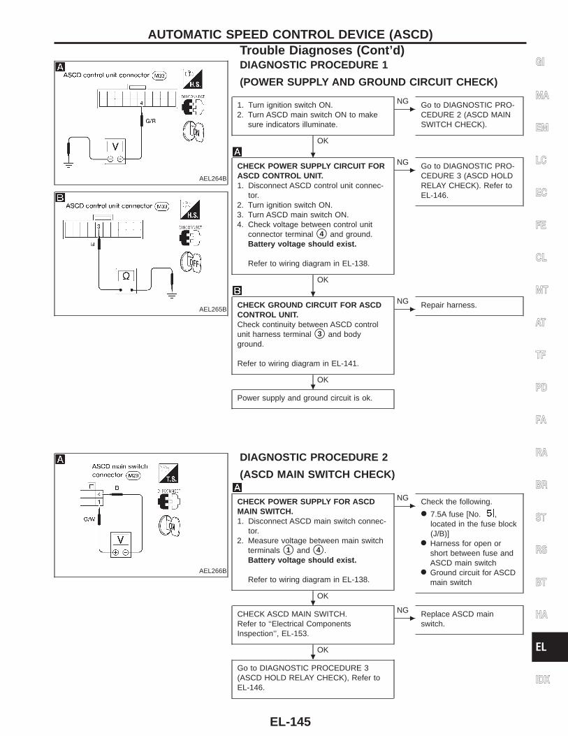
AEL264B
DIAGNOSTIC PROCEDURE 1
(POWER SUPPLY AND GROUND CIRCUIT CHECK)
AEL265B
1. Turn ignition switch ON.2. Turn ASCD main switch ON to make
sure indicators illuminate.
OK
c
NG Go to DIAGNOSTIC PRO-CEDURE 2 (ASCD MAINSWITCH CHECK).
CHECK POWER SUPPLY CIRCUIT FORASCD CONTROL UNIT.1. Disconnect ASCD control unit connec-
tor.2. Turn ignition switch ON.3. Turn ASCD main switch ON.4. Check voltage between control unit
connector terminal s4 and ground.Battery voltage should exist.
Refer to wiring diagram in EL-138.
OK
c
NG Go to DIAGNOSTIC PRO-CEDURE 3 (ASCD HOLDRELAY CHECK). Refer toEL-146.
CHECK GROUND CIRCUIT FOR ASCDCONTROL UNIT.Check continuity between ASCD controlunit harness terminal s3 and bodyground.
Refer to wiring diagram in EL-141.
OK
c
NG Repair harness.
Power supply and ground circuit is ok.
AEL266B
DIAGNOSTIC PROCEDURE 2
(ASCD MAIN SWITCH CHECK)
CHECK POWER SUPPLY FOR ASCDMAIN SWITCH.1. Disconnect ASCD main switch connec-
tor.2. Measure voltage between main switch
terminals s1 and s4 .Battery voltage should exist.
Refer to wiring diagram in EL-138.
OK
c
NG Check the following.
● 7.5A fuse [No. ,located in the fuse block(J/B)]
● Harness for open orshort between fuse andASCD main switch
● Ground circuit for ASCDmain switch
CHECK ASCD MAIN SWITCH.Refer to ‘‘Electrical ComponentsInspection’’, EL-153.
OK
c
NG Replace ASCD mainswitch.
Go to DIAGNOSTIC PROCEDURE 3(ASCD HOLD RELAY CHECK), Refer toEL-146.
GI
MA
EM
LC
EC
FE
CL
MT
AT
TF
PD
FA
RA
BR
ST
RS
BT
HA
EL
IDX
AUTOMATIC SPEED CONTROL DEVICE (ASCD)Trouble Diagnoses (Cont’d)
.
.
.
.
.
EL-145
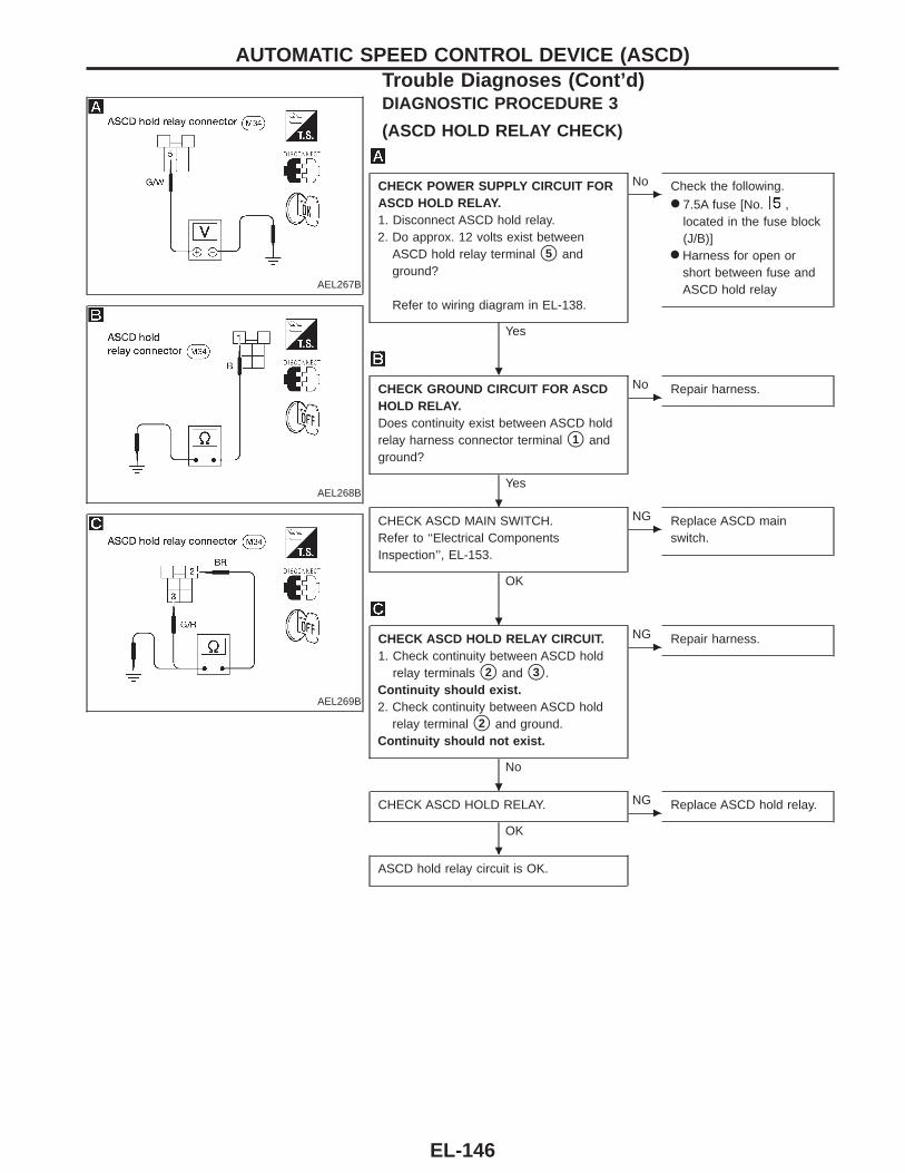
AEL267B
DIAGNOSTIC PROCEDURE 3
(ASCD HOLD RELAY CHECK)
AEL268B
AEL269B
CHECK POWER SUPPLY CIRCUIT FORASCD HOLD RELAY.1. Disconnect ASCD hold relay.2. Do approx. 12 volts exist between
ASCD hold relay terminal s5 andground?
Refer to wiring diagram in EL-138.
Yes
c
No Check the following.● 7.5A fuse [No. ,
located in the fuse block(J/B)]
● Harness for open orshort between fuse andASCD hold relay
CHECK GROUND CIRCUIT FOR ASCDHOLD RELAY.Does continuity exist between ASCD holdrelay harness connector terminal s1 andground?
Yes
c
No Repair harness.
CHECK ASCD MAIN SWITCH.Refer to ‘‘Electrical ComponentsInspection’’, EL-153.
OK
c
NG Replace ASCD mainswitch.
CHECK ASCD HOLD RELAY CIRCUIT.1. Check continuity between ASCD hold
relay terminals s2 and s3 .Continuity should exist.2. Check continuity between ASCD hold
relay terminal s2 and ground.Continuity should not exist.
No
c
NG Repair harness.
CHECK ASCD HOLD RELAY.
OKc
NG Replace ASCD hold relay.
ASCD hold relay circuit is OK.
AUTOMATIC SPEED CONTROL DEVICE (ASCD)Trouble Diagnoses (Cont’d)
.
.
.
.
.
EL-146
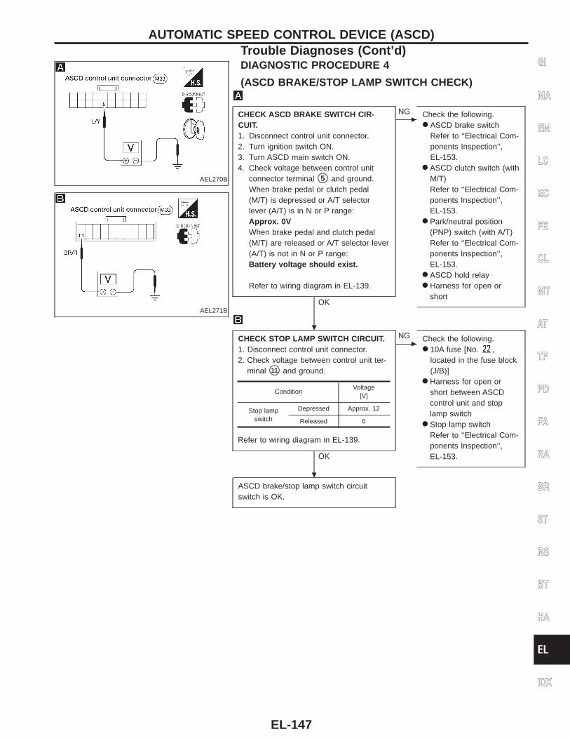
AEL270B
DIAGNOSTIC PROCEDURE 4
(ASCD BRAKE/STOP LAMP SWITCH CHECK)
AEL271B
CHECK ASCD BRAKE SWITCH CIR-CUIT.1. Disconnect control unit connector.2. Turn ignition switch ON.3. Turn ASCD main switch ON.4. Check voltage between control unit
connector terminal s5 and ground.When brake pedal or clutch pedal(M/T) is depressed or A/T selectorlever (A/T) is in N or P range:Approx. 0VWhen brake pedal and clutch pedal(M/T) are released or A/T selector lever(A/T) is not in N or P range:Battery voltage should exist.
Refer to wiring diagram in EL-139.
OK
c
NG Check the following.● ASCD brake switch
Refer to ‘‘Electrical Com-ponents Inspection’’,EL-153.
● ASCD clutch switch (withM/T)Refer to ‘‘Electrical Com-ponents Inspection’’,EL-153.
● Park/neutral position(PNP) switch (with A/T)Refer to ‘‘Electrical Com-ponents Inspection’’,EL-153.
● ASCD hold relay● Harness for open or
short
CHECK STOP LAMP SWITCH CIRCUIT.1. Disconnect control unit connector.2. Check voltage between control unit ter-
minal s11 and ground.
Refer to wiring diagram in EL-139.
OK
c
NG Check the following.● 10A fuse [No. ,
located in the fuse block(J/B)]
● Harness for open orshort between ASCDcontrol unit and stoplamp switch
● Stop lamp switchRefer to ‘‘Electrical Com-ponents Inspection’’,EL-153.
ASCD brake/stop lamp switch circuitswitch is OK.
ConditionVoltage
[V]
Stop lampswitch
Depressed Approx. 12
Released 0
GI
MA
EM
LC
EC
FE
CL
MT
AT
TF
PD
FA
RA
BR
ST
RS
BT
HA
EL
IDX
AUTOMATIC SPEED CONTROL DEVICE (ASCD)Trouble Diagnoses (Cont’d)
.
.
EL-147
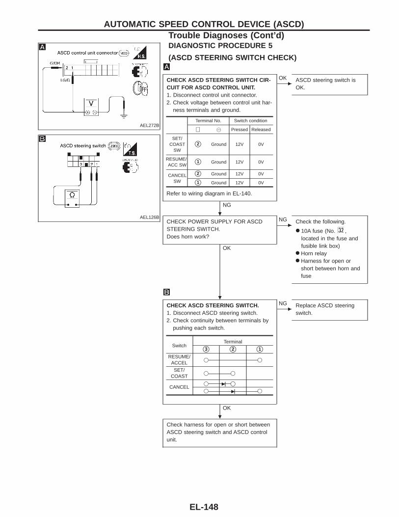
AEL272B
DIAGNOSTIC PROCEDURE 5
(ASCD STEERING SWITCH CHECK)
AEL126B
CHECK ASCD STEERING SWITCH CIR-CUIT FOR ASCD CONTROL UNIT.1. Disconnect control unit connector.2. Check voltage between control unit har-
ness terminals and ground.
Refer to wiring diagram in EL-140.
NG
c
OK ASCD steering switch isOK.
CHECK POWER SUPPLY FOR ASCDSTEERING SWITCH.Does horn work?
OK
c
NG Check the following.
● 10A fuse (No. ,located in the fuse andfusible link box)
● Horn relay● Harness for open or
short between horn andfuse
CHECK ASCD STEERING SWITCH.1. Disconnect ASCD steering switch.2. Check continuity between terminals by
pushing each switch.
OK
c
NG Replace ASCD steeringswitch.
Check harness for open or short betweenASCD steering switch and ASCD controlunit.
Terminal No. Switch condition
⊕ @ Pressed Released
SET/COAST
SWs2 Ground 12V 0V
RESUME/ACC SW s1 Ground 12V 0V
CANCELSW
s2 Ground 12V 0V
s1 Ground 12V 0V
SwitchTerminal
s3 s2 s1
RESUME/ACCEL
j j
SET/COAST
j j
CANCELj c j
j c j
AUTOMATIC SPEED CONTROL DEVICE (ASCD)Trouble Diagnoses (Cont’d)
.
.
.
EL-148
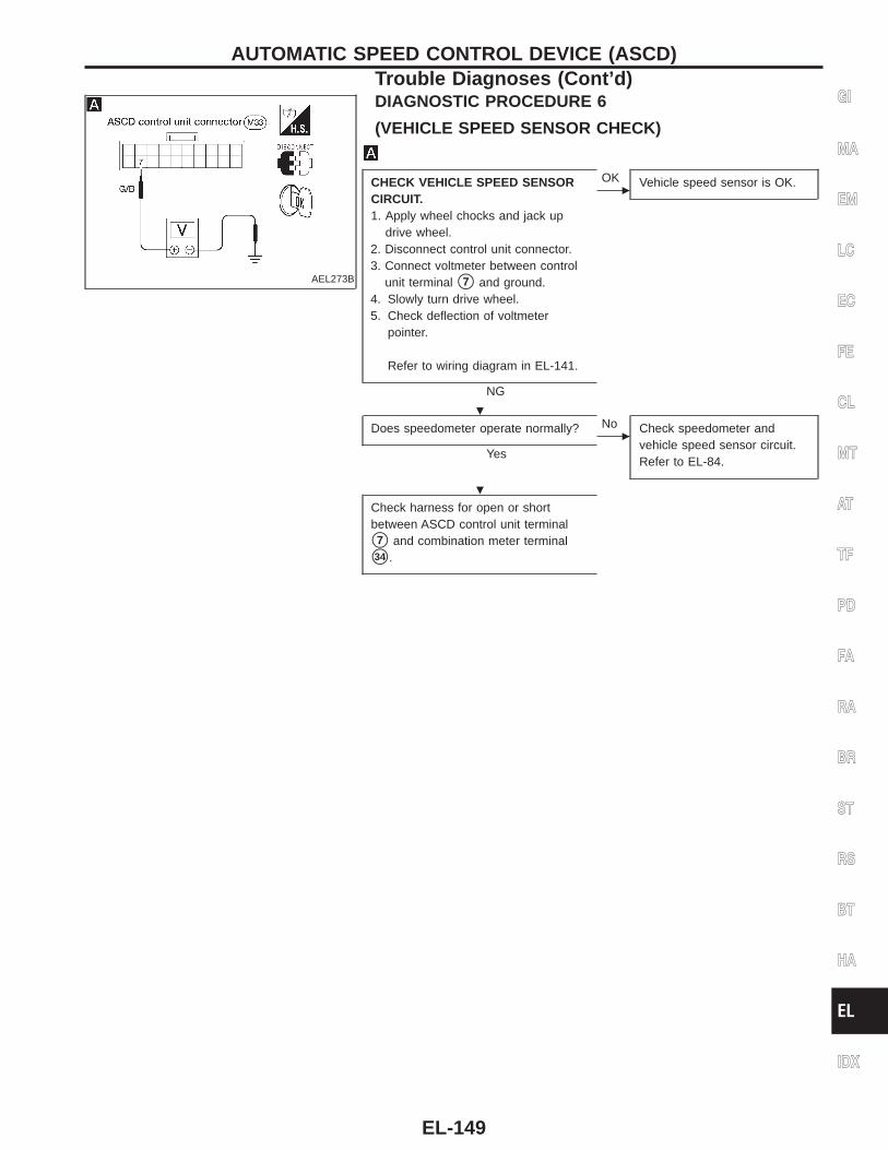
AEL273B
DIAGNOSTIC PROCEDURE 6
(VEHICLE SPEED SENSOR CHECK)
CHECK VEHICLE SPEED SENSORCIRCUIT.1. Apply wheel chocks and jack up
drive wheel.2. Disconnect control unit connector.3. Connect voltmeter between control
unit terminal s7 and ground.4. Slowly turn drive wheel.5. Check deflection of voltmeter
pointer.
Refer to wiring diagram in EL-141.
NG
c
OK Vehicle speed sensor is OK.
Does speedometer operate normally?
Yesc
No Check speedometer andvehicle speed sensor circuit.Refer to EL-84.
Check harness for open or shortbetween ASCD control unit terminal
s7 and combination meter terminal
s34 .
GI
MA
EM
LC
EC
FE
CL
MT
AT
TF
PD
FA
RA
BR
ST
RS
BT
HA
EL
IDX
AUTOMATIC SPEED CONTROL DEVICE (ASCD)Trouble Diagnoses (Cont’d)
.
.
EL-149
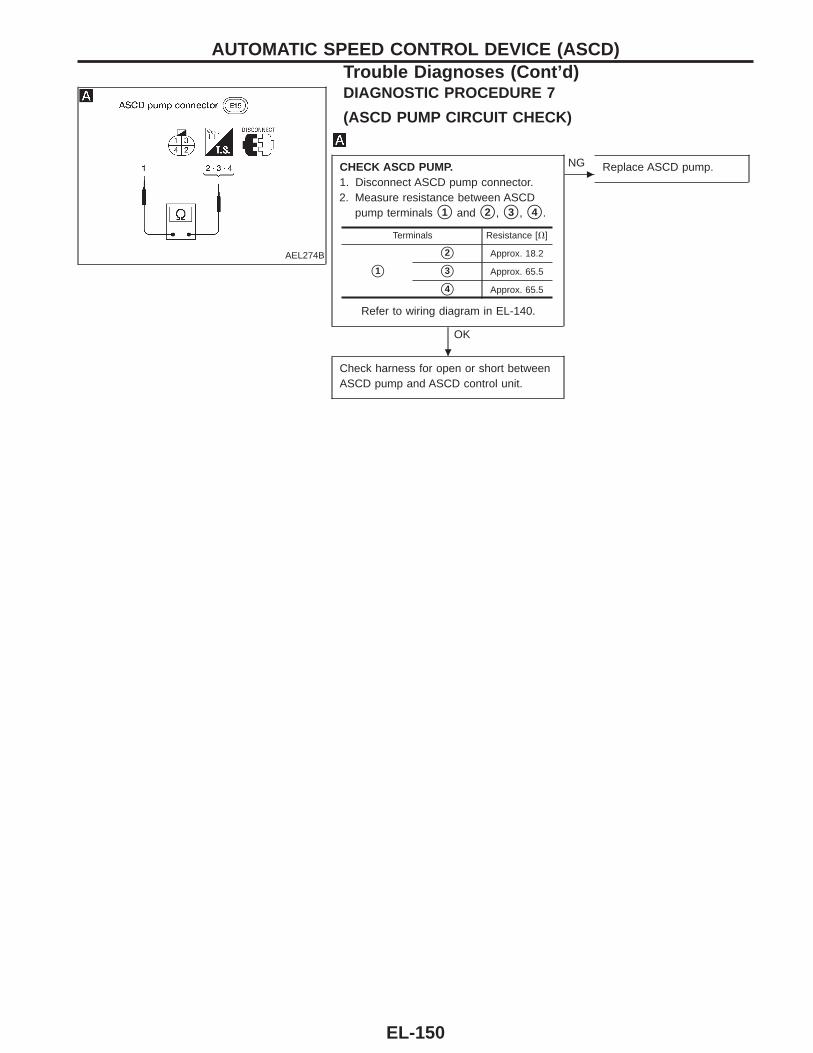
AEL274B
DIAGNOSTIC PROCEDURE 7
(ASCD PUMP CIRCUIT CHECK)
CHECK ASCD PUMP.1. Disconnect ASCD pump connector.2. Measure resistance between ASCD
pump terminals s1 and s2 , s3 , s4 .
Refer to wiring diagram in EL-140.
OK
c
NG Replace ASCD pump.
Check harness for open or short betweenASCD pump and ASCD control unit.
Terminals Resistance [V]
s1
s2 Approx. 18.2
s3 Approx. 65.5
s4 Approx. 65.5
AUTOMATIC SPEED CONTROL DEVICE (ASCD)Trouble Diagnoses (Cont’d)
.
EL-150
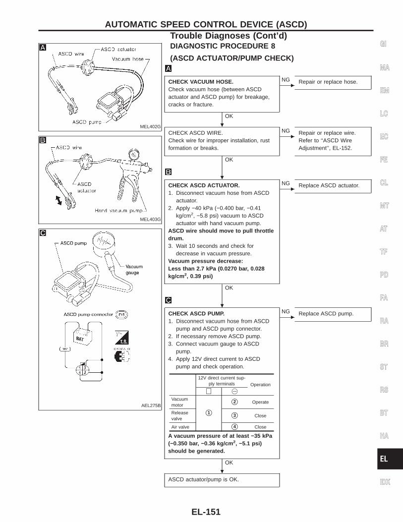
MEL402G
DIAGNOSTIC PROCEDURE 8
(ASCD ACTUATOR/PUMP CHECK)
MEL403G
AEL275B
CHECK VACUUM HOSE.Check vacuum hose (between ASCDactuator and ASCD pump) for breakage,cracks or fracture.
OK
c
NG Repair or replace hose.
CHECK ASCD WIRE.Check wire for improper installation, rustformation or breaks.
OK
c
NG Repair or replace wire.Refer to ‘‘ASCD WireAdjustment’’, EL-152.
CHECK ASCD ACTUATOR.1. Disconnect vacuum hose from ASCD
actuator.2. Apply −40 kPa (−0.400 bar, −0.41
kg/cm2, −5.8 psi) vacuum to ASCDactuator with hand vacuum pump.
ASCD wire should move to pull throttledrum.3. Wait 10 seconds and check for
decrease in vacuum pressure.Vacuum pressure decrease:Less than 2.7 kPa (0.0270 bar, 0.028kg/cm 2, 0.39 psi)
OK
c
NG Replace ASCD actuator.
CHECK ASCD PUMP.1. Disconnect vacuum hose from ASCD
pump and ASCD pump connector.2. If necessary remove ASCD pump.3. Connect vacuum gauge to ASCD
pump.4. Apply 12V direct current to ASCD
pump and check operation.
A vacuum pressure of at least −35 kPa(−0.350 bar, −0.36 kg/cm 2, −5.1 psi)should be generated.
OK
c
NG Replace ASCD pump.
ASCD actuator/pump is OK.
12V direct current sup-ply terminals Operation
⊕ @
Vacuummotor
s1
s2 Operate
Releasevalve s3 Close
Air valve s4 Close
GI
MA
EM
LC
EC
FE
CL
MT
AT
TF
PD
FA
RA
BR
ST
RS
BT
HA
EL
IDX
AUTOMATIC SPEED CONTROL DEVICE (ASCD)Trouble Diagnoses (Cont’d)
.
.
.
.
EL-151
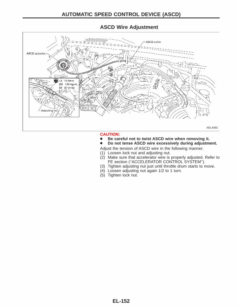
ASCD Wire Adjustment
AEL436C
CAUTION:● Be careful not to twist ASCD wire when removing it.● Do not tense ASCD wire excessively during adjustment.Adjust the tension of ASCD wire in the following manner.(1) Loosen lock nut and adjusting nut.(2) Make sure that accelerator wire is properly adjusted. Refer to
FE section (‘‘ACCELERATOR CONTROL SYSTEM’’).(3) Tighten adjusting nut just until throttle drum starts to move.(4) Loosen adjusting nut again 1/2 to 1 turn.(5) Tighten lock nut.
AUTOMATIC SPEED CONTROL DEVICE (ASCD)
EL-152
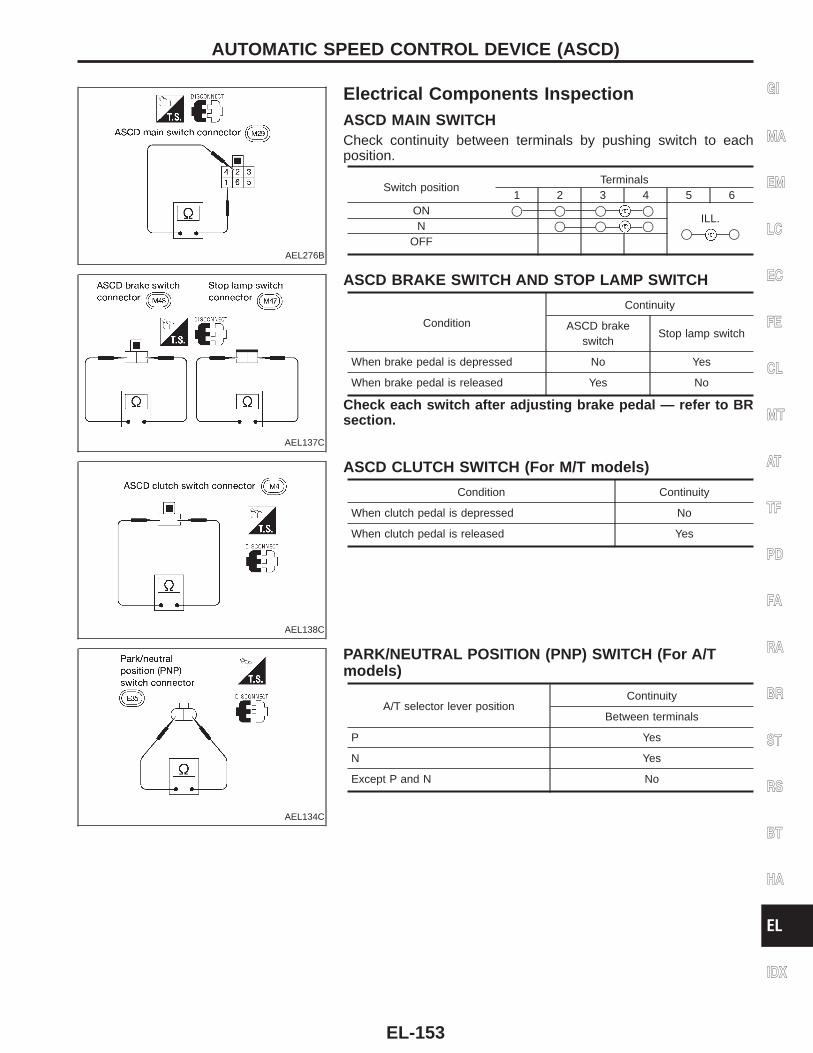
AEL276B
Electrical Components InspectionASCD MAIN SWITCHCheck continuity between terminals by pushing switch to eachposition.
Switch positionTerminals
1 2 3 4 5 6ON j j j j
ILL.j j
N j j j
OFF
AEL137C
ASCD BRAKE SWITCH AND STOP LAMP SWITCH
Condition
Continuity
ASCD brakeswitch
Stop lamp switch
When brake pedal is depressed No Yes
When brake pedal is released Yes No
Check each switch after adjusting brake pedal — refer to BRsection.
AEL138C
ASCD CLUTCH SWITCH (For M/T models)
Condition Continuity
When clutch pedal is depressed No
When clutch pedal is released Yes
AEL134C
PARK/NEUTRAL POSITION (PNP) SWITCH (For A/Tmodels)
A/T selector lever positionContinuity
Between terminals
P Yes
N Yes
Except P and N No
GI
MA
EM
LC
EC
FE
CL
MT
AT
TF
PD
FA
RA
BR
ST
RS
BT
HA
EL
IDX
AUTOMATIC SPEED CONTROL DEVICE (ASCD)
EL-153
System DescriptionPower is supplied at all times:● from 30A fusible link (Letter , located in the fuse and fusible link box)● to circuit breaker terminal s1● through circuit breaker terminal s2● to power window relay terminal s5 .With ignition switch in ON or START position, power is supplied:● through 7.5A fuse [No. located in the fuse block (J/B)]● to power window relay terminal s2 .Ground is supplied to power window relay terminal s1 :● through body grounds sM68 and sM14 .The power window relay is energized and power is supplied:● through power window relay terminal s3● to main power window and door lock/unlock switch terminal s1 ,● to power window switch RH terminal s4 .
MANUAL OPERATION
Door LHGround is supplied:● through body grounds sM14 and sM68● to main power window and door lock/unlock switch terminal s5 .
WINDOW UPWhen the LH switch in the main power window and door lock/unlock switch is pressed in the UP position,power is supplied:● through main power window and door lock/unlock switch terminal s16
● to power window motor LH terminal sUP .Ground is supplied:● through main power window and door lock/unlock switch terminal s15
● to power window motor LH terminal sDN .Then, the motor raises the window until the switch is released.
WINDOW DOWNWhen the LH switch in the main power window and door lock/unlock switch is pressed in the DOWN position,power is supplied:● through main power window and door lock/unlock switch terminal s15
● to power window motor LH terminal sDN .Ground is supplied:● through main power window and door lock/unlock switch terminal s16
● to power window motor LH terminal sUP .Then, the motor lowers the window until the switch is released.
Door RHGround is supplied:● through body grounds sM14 and sM68● to main power window and door lock/unlock switch terminal s5 .
NOTE:Numbers in parentheses are terminal numbers, when power window switch is pressed in the UP and DOWNpositions, respectively.
MAIN SWITCH OPERATIONPower is supplied:● through main power window and door lock/unlock switch terminal (s14 , s13 )● to power window switch RH terminal (s5 , s2 ).The subsequent operation is the same as the power window switch operation.
POWER WINDOW
EL-154
POWER WINDOW SWITCH OPERATIONPower is supplied:● to power window switch RH terminal s4● through power window switch RH terminal (s6 , s3 )● to power window motor RH terminal (sUP , sDN ).Ground is supplied:● to power window motor RH terminal (sDN , sUP )● through power window switch RH terminal (s3 , s6 )● through power window switch RH terminal (s2 , s5 )● through main power window and door lock/unlock switch terminal (s13 , s14 ).Then, the motor raises or lowers the window until the switch is released.
AUTO OPERATIONThe power window AUTO feature enables the driver to lower the driver’s window without holding the windowswitch in the DOWN position.The AUTO feature only operates on the driver’s window downward movement.
POWER WINDOW LOCKThe power window lock is designed to lock operation of the RH door window.When the lock switch is pressed to LOCK position, ground of the power window switch RH in the main powerwindow and door lock/unlock switch is disconnected. This prevents the power window motor RH from operat-ing.
GI
MA
EM
LC
EC
FE
CL
MT
AT
TF
PD
FA
RA
BR
ST
RS
BT
HA
EL
IDX
POWER WINDOWSystem Description (Cont’d)
EL-155
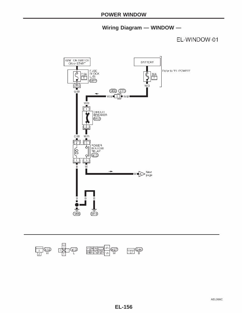
Wiring Diagram — WINDOW —
AEL066C
POWER WINDOW
EL-156
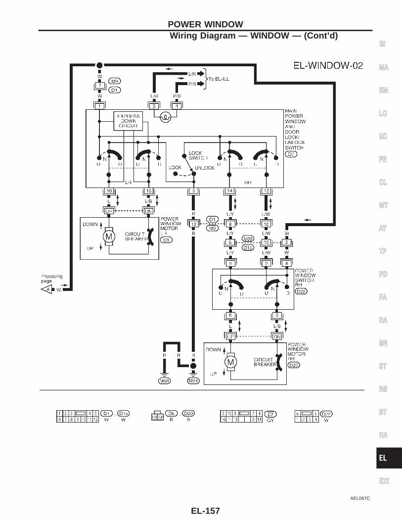
AEL067C
GI
MA
EM
LC
EC
FE
CL
MT
AT
TF
PD
FA
RA
BR
ST
RS
BT
HA
EL
IDX
POWER WINDOWWiring Diagram — WINDOW — (Cont’d)
EL-157
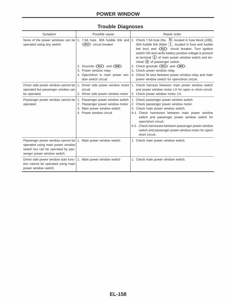
Trouble DiagnosesSymptom Possible cause Repair order
None of the power windows can beoperated using any switch.
1. 7.5A fuse, 30A fusible link and
sM12 circuit breaker
2. Grounds sM14 and sM68
3. Power window relay4. Open/short in main power win-
dow switch circuit
1. Check 7.5A fuse (No. , located in fuse block [J/B]),30A fusible link (letter , located in fuse and fusiblelink box) and sM12 circuit breaker. Turn ignitionswitch ON and verify battery positive voltage is presentat terminal s1 of main power window switch and ter-minal s4 of passenger switch.
2. Check grounds sM14 and sM68 .3. Check power window relay.4. Check W wire between power window relay and main
power window switch for open/short circuit.
Driver side power window cannot beoperated but passenger window canbe operated.
1. Driver side power window motorcircuit
2. Driver side power window motor
1. Check harness between main power window switchand power window motor LH for open or short circuit.
2. Check power window motor LH.
Passenger power window cannot beoperated.
1. Passenger power window switch2. Passenger power window motor3. Main power window switch4. Power window circuit
1. Check passenger power window switch.2. Check passenger power window motor.3. Check main power window switch.4-1. Check harnesses between main power window
switch and passenger power window switch foropen/short circuit.
4-2. Check harnesses between passenger power windowswitch and passenger power window motor for open/short circuit.
Passenger power window cannot beoperated using main power windowswitch but can be operated by pas-senger power window switch.
1. Main power window switch 1. Check main power window switch.
Driver side power window auto func-tion cannot be operated using mainpower window switch.
1. Main power window switch 1. Check main power window switch.
POWER WINDOW
EL-158
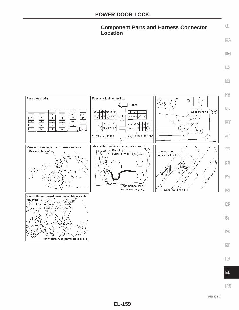
Component Parts and Harness ConnectorLocation
AEL309C
GI
MA
EM
LC
EC
FE
CL
MT
AT
TF
PD
FA
RA
BR
ST
RS
BT
HA
EL
IDX
POWER DOOR LOCK
EL-159
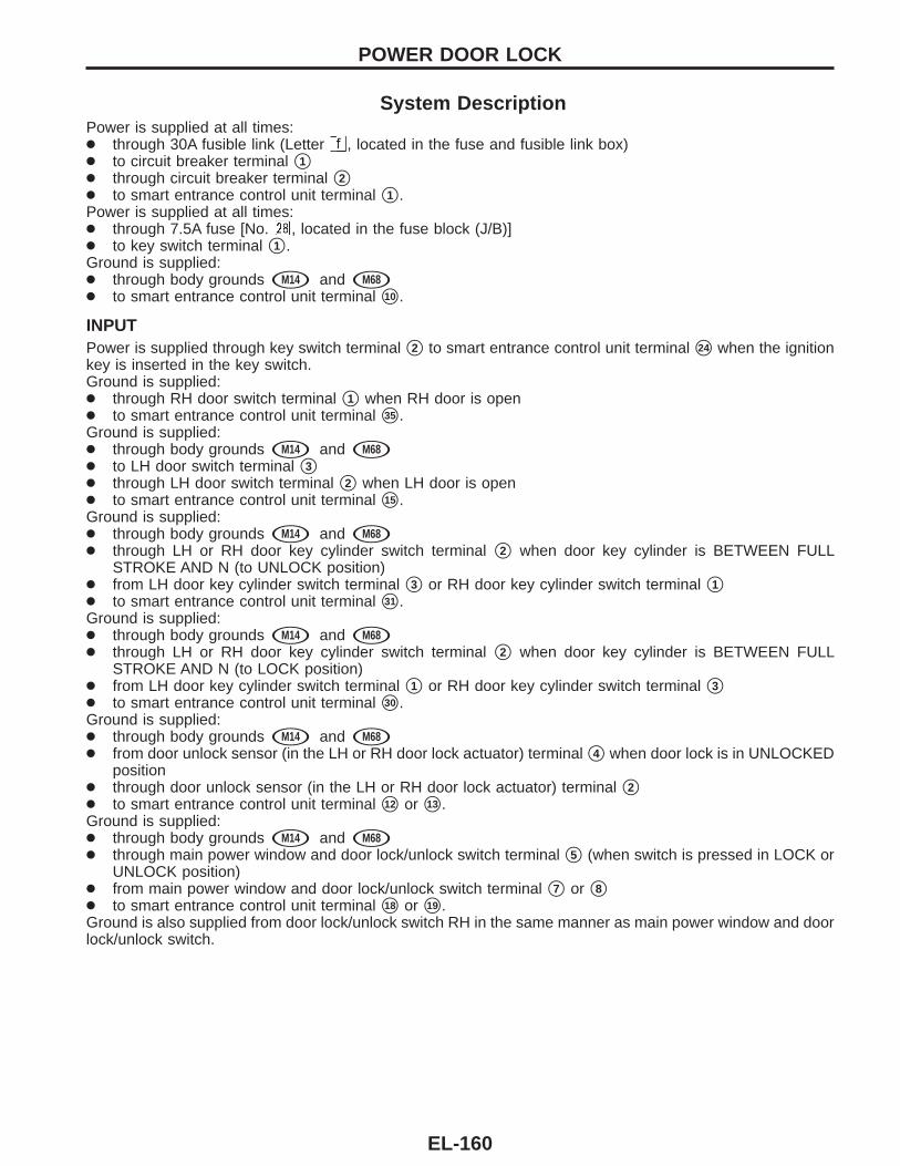
System DescriptionPower is supplied at all times:● through 30A fusible link (Letter , located in the fuse and fusible link box)● to circuit breaker terminal s1● through circuit breaker terminal s2● to smart entrance control unit terminal s1 .Power is supplied at all times:● through 7.5A fuse [No. , located in the fuse block (J/B)]● to key switch terminal s1 .Ground is supplied:● through body grounds sM14 and sM68● to smart entrance control unit terminal s10 .
INPUTPower is supplied through key switch terminal s2 to smart entrance control unit terminal s24 when the ignitionkey is inserted in the key switch.Ground is supplied:● through RH door switch terminal s1 when RH door is open● to smart entrance control unit terminal s35 .Ground is supplied:● through body grounds sM14 and sM68● to LH door switch terminal s3● through LH door switch terminal s2 when LH door is open● to smart entrance control unit terminal s15 .Ground is supplied:● through body grounds sM14 and sM68● through LH or RH door key cylinder switch terminal s2 when door key cylinder is BETWEEN FULL
STROKE AND N (to UNLOCK position)● from LH door key cylinder switch terminal s3 or RH door key cylinder switch terminal s1● to smart entrance control unit terminal s31 .Ground is supplied:● through body grounds sM14 and sM68● through LH or RH door key cylinder switch terminal s2 when door key cylinder is BETWEEN FULL
STROKE AND N (to LOCK position)● from LH door key cylinder switch terminal s1 or RH door key cylinder switch terminal s3● to smart entrance control unit terminal s30 .Ground is supplied:● through body grounds sM14 and sM68● from door unlock sensor (in the LH or RH door lock actuator) terminal s4 when door lock is in UNLOCKED
position● through door unlock sensor (in the LH or RH door lock actuator) terminal s2● to smart entrance control unit terminal s12 or s13 .Ground is supplied:● through body grounds sM14 and sM68● through main power window and door lock/unlock switch terminal s5 (when switch is pressed in LOCK or
UNLOCK position)● from main power window and door lock/unlock switch terminal s7 or s8● to smart entrance control unit terminal s18 or s19 .Ground is also supplied from door lock/unlock switch RH in the same manner as main power window and doorlock/unlock switch.
POWER DOOR LOCK
EL-160
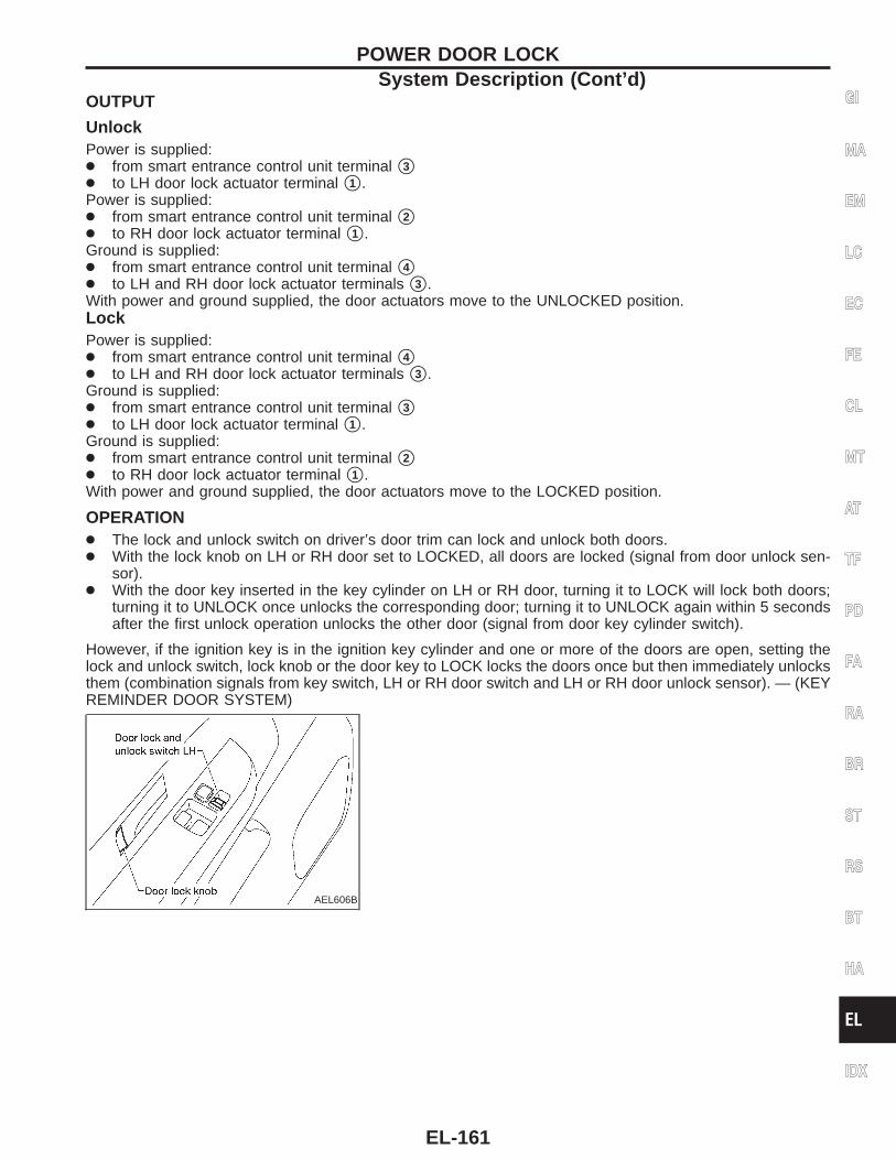
OUTPUT
UnlockPower is supplied:● from smart entrance control unit terminal s3● to LH door lock actuator terminal s1 .Power is supplied:● from smart entrance control unit terminal s2● to RH door lock actuator terminal s1 .Ground is supplied:● from smart entrance control unit terminal s4● to LH and RH door lock actuator terminals s3 .With power and ground supplied, the door actuators move to the UNLOCKED position.LockPower is supplied:● from smart entrance control unit terminal s4● to LH and RH door lock actuator terminals s3 .Ground is supplied:● from smart entrance control unit terminal s3● to LH door lock actuator terminal s1 .Ground is supplied:● from smart entrance control unit terminal s2● to RH door lock actuator terminal s1 .With power and ground supplied, the door actuators move to the LOCKED position.
OPERATION● The lock and unlock switch on driver’s door trim can lock and unlock both doors.● With the lock knob on LH or RH door set to LOCKED, all doors are locked (signal from door unlock sen-
sor).● With the door key inserted in the key cylinder on LH or RH door, turning it to LOCK will lock both doors;
turning it to UNLOCK once unlocks the corresponding door; turning it to UNLOCK again within 5 secondsafter the first unlock operation unlocks the other door (signal from door key cylinder switch).
However, if the ignition key is in the ignition key cylinder and one or more of the doors are open, setting thelock and unlock switch, lock knob or the door key to LOCK locks the doors once but then immediately unlocksthem (combination signals from key switch, LH or RH door switch and LH or RH door unlock sensor). — (KEYREMINDER DOOR SYSTEM)
AEL606B
GI
MA
EM
LC
EC
FE
CL
MT
AT
TF
PD
FA
RA
BR
ST
RS
BT
HA
EL
IDX
POWER DOOR LOCKSystem Description (Cont’d)
EL-161
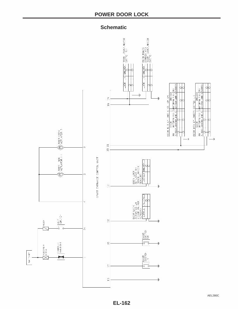
Schematic
AEL280C
POWER DOOR LOCK
EL-162
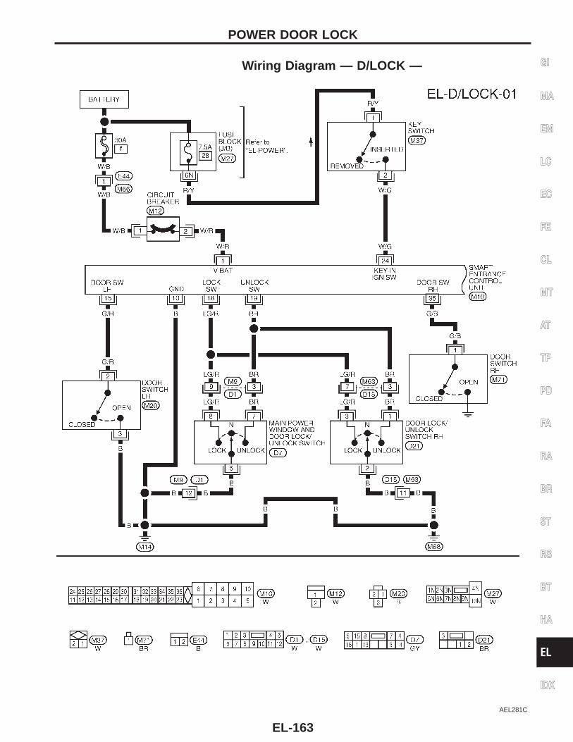
Wiring Diagram — D/LOCK —
AEL281C
GI
MA
EM
LC
EC
FE
CL
MT
AT
TF
PD
FA
RA
BR
ST
RS
BT
HA
EL
IDX
POWER DOOR LOCK
EL-163
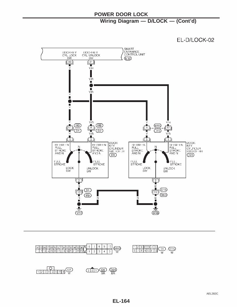
AEL282C
POWER DOOR LOCKWiring Diagram — D/LOCK — (Cont’d)
EL-164
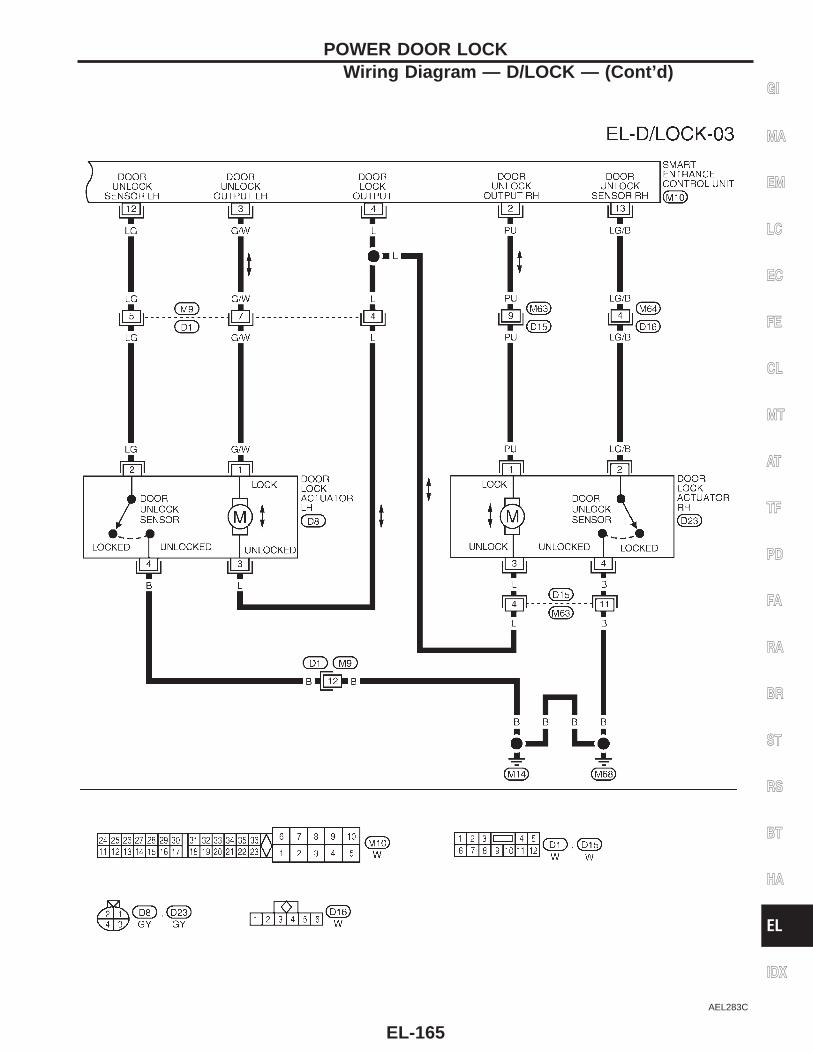
AEL283C
GI
MA
EM
LC
EC
FE
CL
MT
AT
TF
PD
FA
RA
BR
ST
RS
BT
HA
EL
IDX
POWER DOOR LOCKWiring Diagram — D/LOCK — (Cont’d)
EL-165
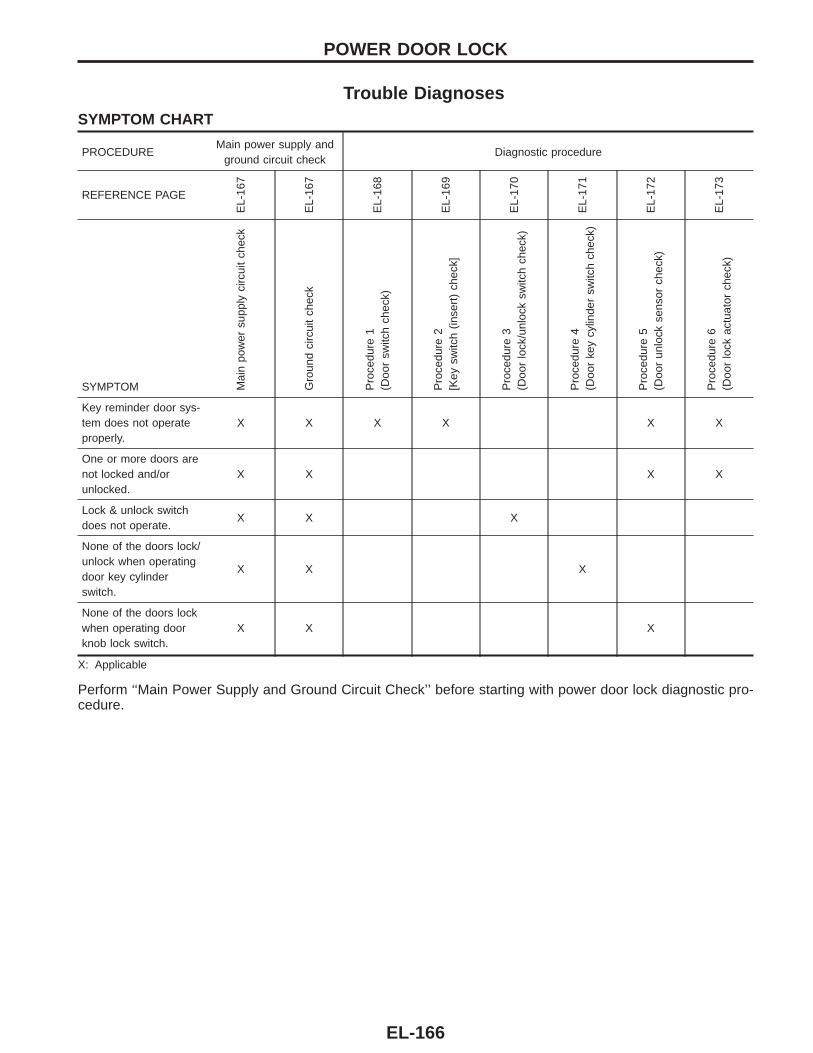
Trouble DiagnosesSYMPTOM CHART
PROCEDUREMain power supply and
ground circuit checkDiagnostic procedure
REFERENCE PAGE
EL-
167
EL-
167
EL-
168
EL-
169
EL-
170
EL-
171
EL-
172
EL-
173
SYMPTOM Mai
npo
wer
supp
lyci
rcui
tch
eck
Gro
und
circ
uit
chec
k
Pro
cedu
re1
(Doo
rsw
itch
chec
k)
Pro
cedu
re2
[Key
switc
h(in
sert
)ch
eck]
Pro
cedu
re3
(Doo
rlo
ck/u
nloc
ksw
itch
chec
k)
Pro
cedu
re4
(Doo
rke
ycy
linde
rsw
itch
chec
k)
Pro
cedu
re5
(Doo
run
lock
sens
orch
eck)
Pro
cedu
re6
(Doo
rlo
ckac
tuat
orch
eck)
Key reminder door sys-tem does not operateproperly.
X X X X X X
One or more doors arenot locked and/orunlocked.
X X X X
Lock & unlock switchdoes not operate.
X X X
None of the doors lock/unlock when operatingdoor key cylinderswitch.
X X X
None of the doors lockwhen operating doorknob lock switch.
X X X
X: Applicable
Perform ‘‘Main Power Supply and Ground Circuit Check’’ before starting with power door lock diagnostic pro-cedure.
POWER DOOR LOCK
EL-166
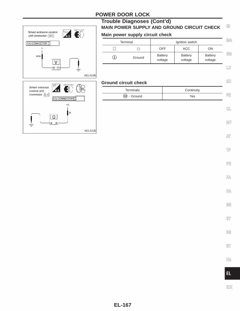
AEL410B
MAIN POWER SUPPLY AND GROUND CIRCUIT CHECK
Main power supply circuit check
Terminal Ignition switch
⊕ @ OFF ACC ON
s1 GroundBatteryvoltage
Batteryvoltage
Batteryvoltage
AEL411B
Ground circuit check
Terminals Continuity
s10 - Ground Yes
GI
MA
EM
LC
EC
FE
CL
MT
AT
TF
PD
FA
RA
BR
ST
RS
BT
HA
EL
IDX
POWER DOOR LOCKTrouble Diagnoses (Cont’d)
EL-167
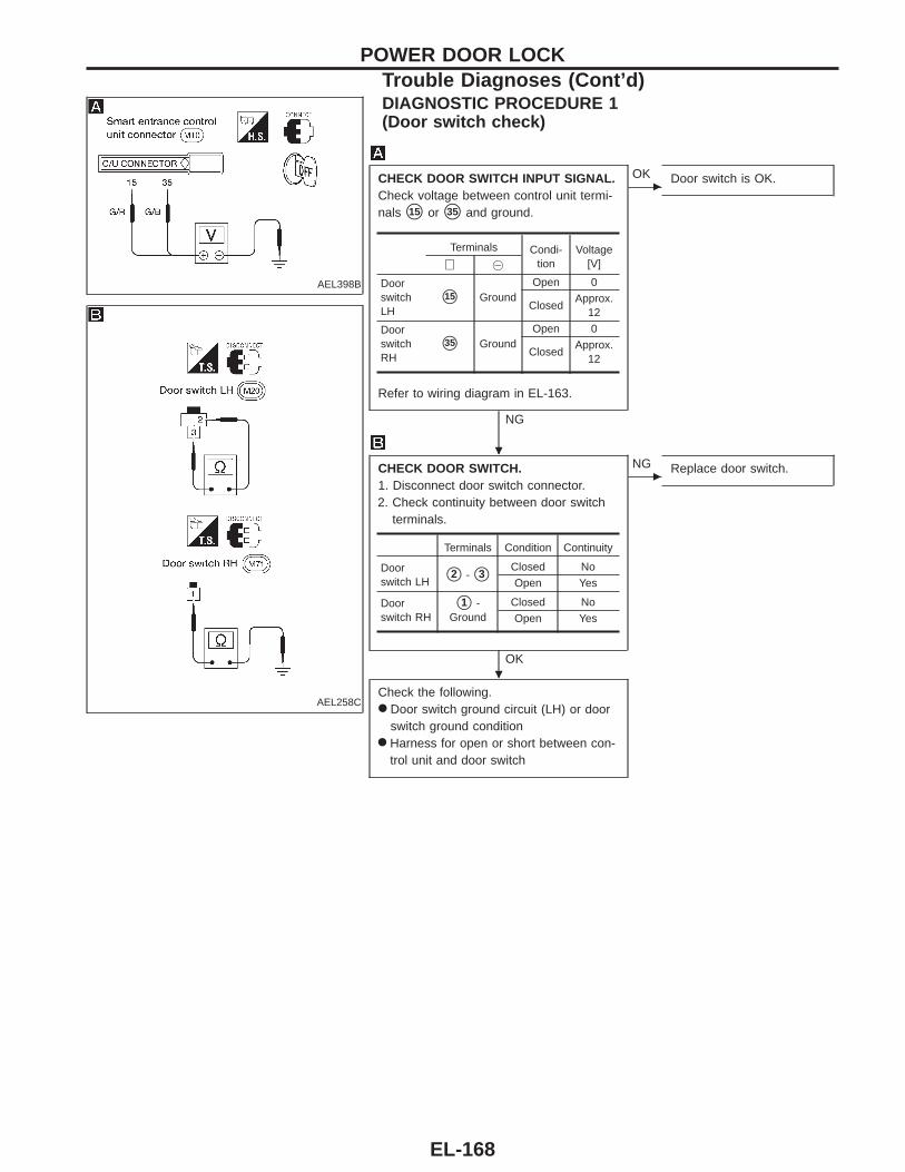
AEL398B
DIAGNOSTIC PROCEDURE 1(Door switch check)
AEL258C
CHECK DOOR SWITCH INPUT SIGNAL.Check voltage between control unit termi-nals s15 or s35 and ground.
Refer to wiring diagram in EL-163.
NG
c
OK Door switch is OK.
CHECK DOOR SWITCH.1. Disconnect door switch connector.2. Check continuity between door switch
terminals.
OK
c
NG Replace door switch.
Check the following.● Door switch ground circuit (LH) or door
switch ground condition● Harness for open or short between con-
trol unit and door switch
Terminals Condi-tion
Voltage[V]⊕ @
DoorswitchLH
s15 GroundOpen 0
ClosedApprox.
12
DoorswitchRH
s35 GroundOpen 0
ClosedApprox.
12
Terminals Condition Continuity
Doorswitch LH s2 - s3
Closed No
Open Yes
Doorswitch RH
s1 -Ground
Closed No
Open Yes
POWER DOOR LOCKTrouble Diagnoses (Cont’d)
.
.
EL-168
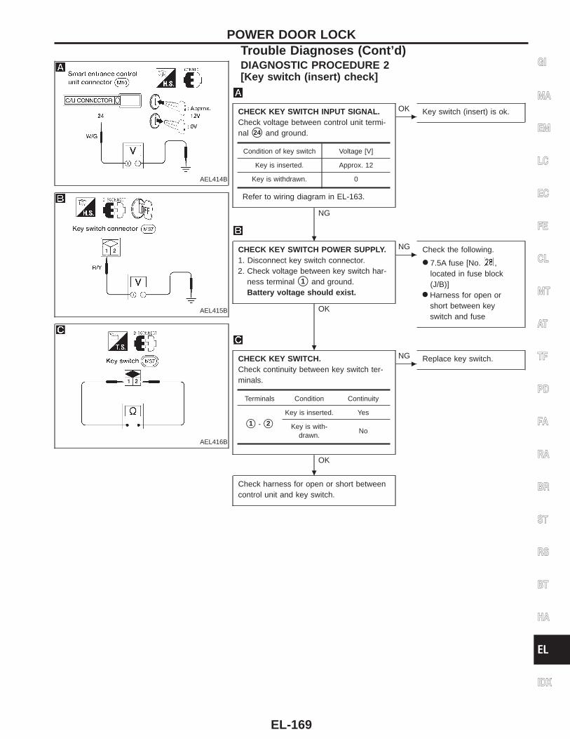
AEL414B
DIAGNOSTIC PROCEDURE 2[Key switch (insert) check]
AEL415B
AEL416B
CHECK KEY SWITCH INPUT SIGNAL.Check voltage between control unit termi-nal s24 and ground.
Refer to wiring diagram in EL-163.
NG
c
OK Key switch (insert) is ok.
CHECK KEY SWITCH POWER SUPPLY.1. Disconnect key switch connector.2. Check voltage between key switch har-
ness terminal s1 and ground.Battery voltage should exist.
OK
c
NG Check the following.
● 7.5A fuse [No. ,located in fuse block(J/B)]
● Harness for open orshort between keyswitch and fuse
CHECK KEY SWITCH.Check continuity between key switch ter-minals.
OK
c
NG Replace key switch.
Check harness for open or short betweencontrol unit and key switch.
Condition of key switch Voltage [V]
Key is inserted. Approx. 12
Key is withdrawn. 0
Terminals Condition Continuity
s1 - s2
Key is inserted. Yes
Key is with-drawn.
No
GI
MA
EM
LC
EC
FE
CL
MT
AT
TF
PD
FA
RA
BR
ST
RS
BT
HA
EL
IDX
POWER DOOR LOCKTrouble Diagnoses (Cont’d)
.
.
.
EL-169
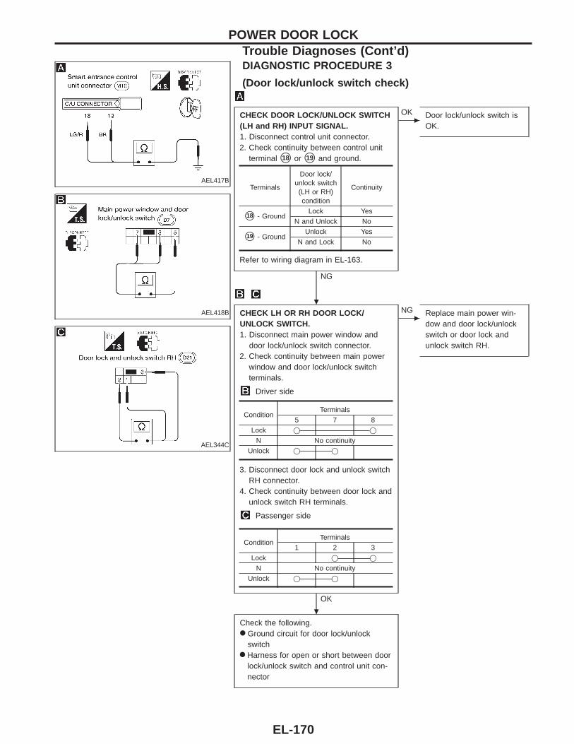
AEL417B
AEL418B
AEL344C
DIAGNOSTIC PROCEDURE 3
(Door lock/unlock switch check)
CHECK DOOR LOCK/UNLOCK SWITCH(LH and RH) INPUT SIGNAL.1. Disconnect control unit connector.2. Check continuity between control unit
terminal s18 or s19 and ground.
Refer to wiring diagram in EL-163.
NG
c
OK Door lock/unlock switch isOK.
CHECK LH OR RH DOOR LOCK/UNLOCK SWITCH.1. Disconnect main power window and
door lock/unlock switch connector.2. Check continuity between main power
window and door lock/unlock switchterminals.
Driver side
3. Disconnect door lock and unlock switchRH connector.
4. Check continuity between door lock andunlock switch RH terminals.
Passenger side
OK
c
NG Replace main power win-dow and door lock/unlockswitch or door lock andunlock switch RH.
Check the following.● Ground circuit for door lock/unlock
switch● Harness for open or short between door
lock/unlock switch and control unit con-nector
Terminals
Door lock/unlock switch(LH or RH)condition
Continuity
s18 - GroundLock Yes
N and Unlock No
s19 - GroundUnlock Yes
N and Lock No
ConditionTerminals
5 7 8
Lock j j
N No continuity
Unlock j j
ConditionTerminals
1 2 3
Lock j j
N No continuity
Unlock j j
POWER DOOR LOCKTrouble Diagnoses (Cont’d)
.
.
EL-170

AEL259C
DIAGNOSTIC PROCEDURE 4(Door key cylinder switch check)
AEL436B
CHECK DOOR KEY CYLINDER SWITCH(LH and RH) INPUT SIGNAL (LOCK/UNLOCK SIGNAL).Check voltage between control unit termi-nals s30 or s31 and ground.
Refer to wiring diagram in EL-164.
NG
c
OK Door key cylinder switch isOK.
CHECK DOOR KEY CYLINDERSWITCH.1. Disconnect door key cylinder switch
connector.2. Check continuity between door key cyl-
inder switch terminals.
OK
c
NG Replace door key cylinderswitch.
Check the following.● Door key cylinder switch ground circuit● Harness for open or short between con-
trol unit and door key cylinder switch
Terminals Key posi-tion
Voltage[V]⊕ @
s30 GroundNeutral
Approx.12
Lock 0
s31 GroundNeutral
Approx.12
Unlock 0
Terminals Key position Continuity
LH: s1 - s2
RH: s3 - s2
Neutral No
Lock Yes
LH: s3 - s2
RH: s1 - s2
Neutral No
Unlock Yes
GI
MA
EM
LC
EC
FE
CL
MT
AT
TF
PD
FA
RA
BR
ST
RS
BT
HA
EL
IDX
POWER DOOR LOCKTrouble Diagnoses (Cont’d)
.
.
EL-171
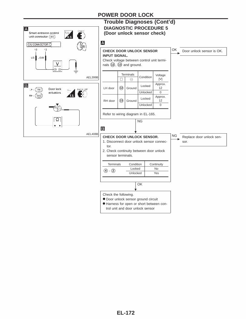
AEL399B
DIAGNOSTIC PROCEDURE 5(Door unlock sensor check)
AEL408B
CHECK DOOR UNLOCK SENSORINPUT SIGNAL.Check voltage between control unit termi-nals s12 , s13 and ground.
Refer to wiring diagram in EL-165.
NG
c
OK Door unlock sensor is OK.
CHECK DOOR UNLOCK SENSOR.1. Disconnect door unlock sensor connec-
tor.2. Check continuity between door unlock
sensor terminals.
OK
c
NG Replace door unlock sen-sor.
Check the following.● Door unlock sensor ground circuit● Harness for open or short between con-
trol unit and door unlock sensor
TerminalsCondition
Voltage[V]⊕ @
LH door s12 GroundLocked
Approx.12
Unlocked 0
RH door s13 GroundLocked
Approx.12
Unlocked 0
Terminals Condition Continuity
s4 - s2Locked No
Unlocked Yes
POWER DOOR LOCKTrouble Diagnoses (Cont’d)
.
.
EL-172
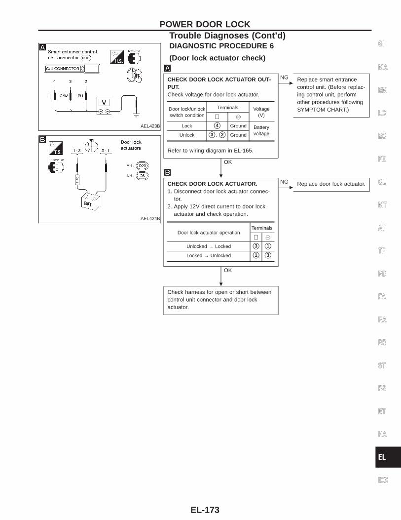
AEL423B
DIAGNOSTIC PROCEDURE 6
(Door lock actuator check)
AEL424B
CHECK DOOR LOCK ACTUATOR OUT-PUT.Check voltage for door lock actuator.
Refer to wiring diagram in EL-165.
OK
c
NG Replace smart entrancecontrol unit. (Before replac-ing control unit, performother procedures followingSYMPTOM CHART.)
CHECK DOOR LOCK ACTUATOR.1. Disconnect door lock actuator connec-
tor.2. Apply 12V direct current to door lock
actuator and check operation.
OK
c
NG Replace door lock actuator.
Check harness for open or short betweencontrol unit connector and door lockactuator.
Door lock/unlockswitch condition
Terminals Voltage(V)⊕ @
Lock s4 Ground BatteryvoltageUnlock s3 , s2 Ground
Door lock actuator operationTerminals
⊕ @
Unlocked → Locked s3 s1
Locked → Unlocked s1 s3
GI
MA
EM
LC
EC
FE
CL
MT
AT
TF
PD
FA
RA
BR
ST
RS
BT
HA
EL
IDX
POWER DOOR LOCKTrouble Diagnoses (Cont’d)
.
.
EL-173
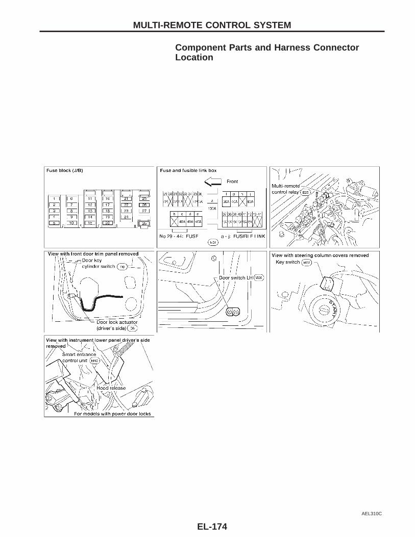
Component Parts and Harness ConnectorLocation
AEL310C
MULTI-REMOTE CONTROL SYSTEM
EL-174
System DescriptionPOWER SUPPLY AND GROUNDPower is supplied at all times:● through 30A fusible link (letter , located in the fuse and fusible link box)● to circuit breaker terminal s1● through circuit breaker terminal s2● to smart entrance control unit terminal s1 .Power is supplied at all times:● through 7.5A fuse [No. , located in the fuse block (J/B)]● to interior lamp terminal s+
Power is supplied at all times:● through 7.5A fuse [No. , located in the fuse block (J/B)]● to key switch terminal s1 .Power is supplied at all times:● through 10A fuse [No. , located in the fuse block (J/B)]● to multi-remote control relay terminals s2 , s5 and s7 .With the ignition switch in the ON or START position, power is supplied:● through 7.5A fuse [No. , located in the fuse block (J/B)]● to smart entrance control unit terminal s11 .With the ignition switch in the ACC or ON position, power is supplied:● through 7.5A fuse [No. , located in the fuse block (J/B)]● to smart entrance control unit terminal s17 .Ground is supplied:● to smart entrance control unit terminal s10
● through body grounds sM14 and sM68 .
INPUTSWhen the key switch is ON (ignition key is inserted in key cylinder), power is supplied:● through key switch terminal s2● to smart entrance control unit terminal s24 .When the door switch LH is OPEN, ground is supplied:● to smart entrance control unit terminal s15
● through door switch LH terminal s2● from door switch LH terminal s3● through body grounds sM14 and sM68 .When the door switch RH is OPEN, ground is supplied:● to smart entrance control unit terminal s35
● through door switch RH terminal s1● through door switch body ground.When the door lock actuator LH (door unlock sensor) is UNLOCKED, ground is supplied:● to smart entrance control unit terminal s12
● through door lock actuator LH (door unlock sensor) terminal s2● to door lock actuator LH (door unlock sensor) terminal s4● through body grounds sM14 and sM68 .When the door lock actuator RH (door unlock sensor) is UNLOCKED, ground is supplied to smart entrancecontrol unit terminal s13 in the same manner as door lock actuator LH.Remote controller signal input:● through internal antenna.The multi-remote control system controls operation of the● power door lock● interior lamp● panic alarm● hazard reminder.
OPERATION PROCEDURE
Power door lock operationWhen the following input signals are both supplied:● key switch REMOVED (when ignition key is not inserted in key cylinder);● door switch CLOSED (when all the doors are closed).
GI
MA
EM
LC
EC
FE
CL
MT
AT
TF
PD
FA
RA
BR
ST
RS
BT
HA
EL
IDX
MULTI-REMOTE CONTROL SYSTEM
EL-175
The above two signals are already input into the smart entrance control unit. At this point, smart entrancecontrol unit receives a LOCK signal from the remote controller. The smart entrance control unit locks all doorswith input of the LOCK signal from the remote controller.And then ground is supplied:● to multi-remote control relay terminal s1● through smart entrance control unit terminal s7 .Multi-remote control relay is now energized, and the hazard warning lamps flash twice as areminder—HAZARD REMINDER . For detailed description, refer to ‘‘TURN SIGNAL AND HAZARD WARNINGLAMPS’’, EL-63.When an UNLOCK signal is sent from the remote controller once, the driver’s door will be unlocked.Then, if an UNLOCK signal is sent from the remote controller again within 5 seconds, the passenger door willbe unlocked.To deactivate the horn chirp when using the remote controller, press both unlock and lock buttons for twoseconds. With the horn deactivated, the exterior lights do not flash when the unlock button is pressed. To acti-vate the horn chirp, press both unlock and lock buttons for two seconds.
Interior lamp operationWhen the following input signals are both supplied:● key switch REMOVED (when ignition key is not inserted in key cylinder);● door switch CLOSED (when all the doors are closed);multi-remote control system turns on interior lamp (for 30 seconds) with input of UNLOCK signal from remotecontroller.For detailed description, refer to ‘‘INTERIOR ROOM LAMP’’, EL-71.
Panic alarm operationWhen key switch is OFF (when ignition key is not inserted in key cylinder), multi-remote control system turnson and off horn and headlamps intermittently with input of PANIC ALARM signal from remote controller.For detailed description, refer to ‘‘THEFT WARNING SYSTEM’’, EL-191.
MULTI-REMOTE CONTROL SYSTEMSystem Description (Cont’d)
EL-176
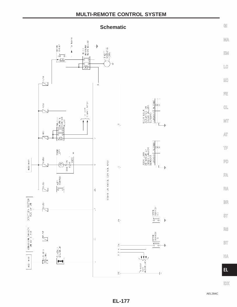
Schematic
AEL284C
GI
MA
EM
LC
EC
FE
CL
MT
AT
TF
PD
FA
RA
BR
ST
RS
BT
HA
EL
IDX
MULTI-REMOTE CONTROL SYSTEM
EL-177
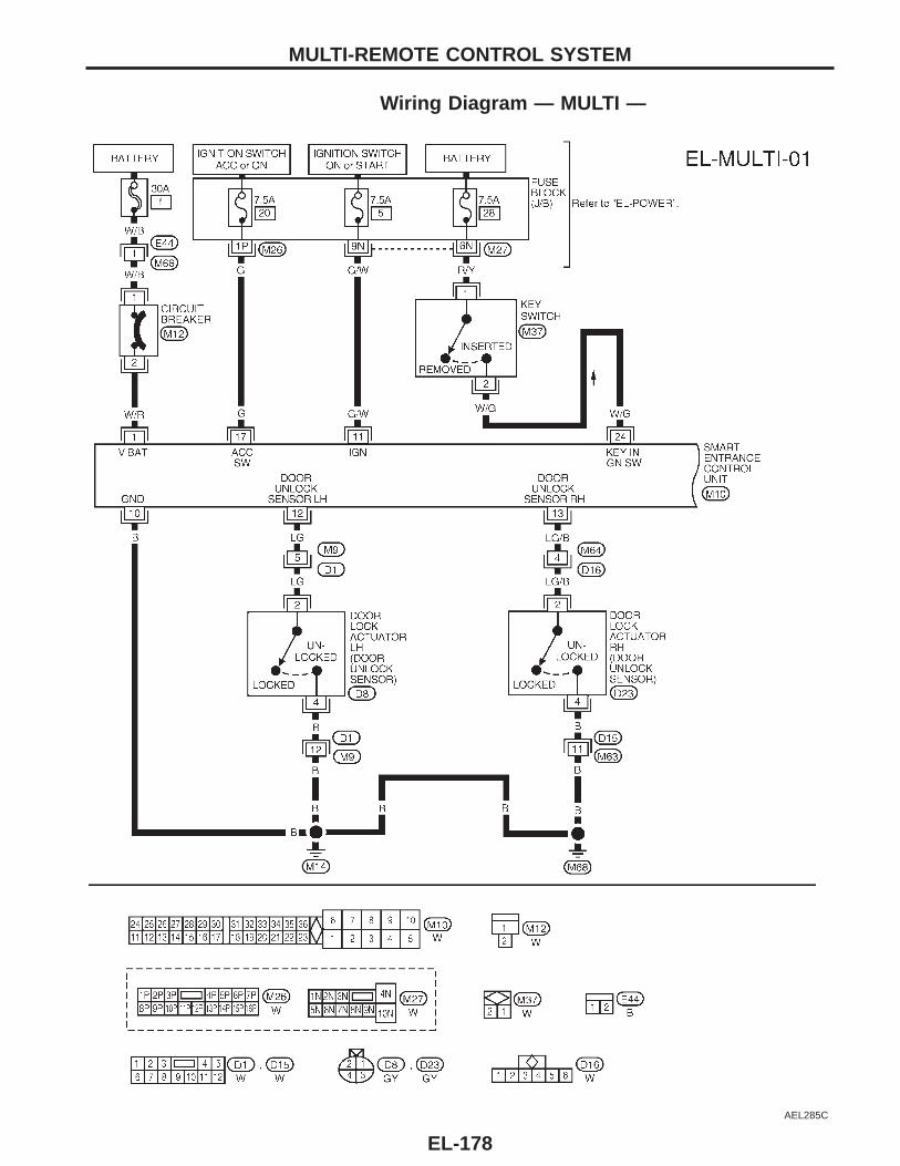
Wiring Diagram — MULTI —
AEL285C
MULTI-REMOTE CONTROL SYSTEM
EL-178
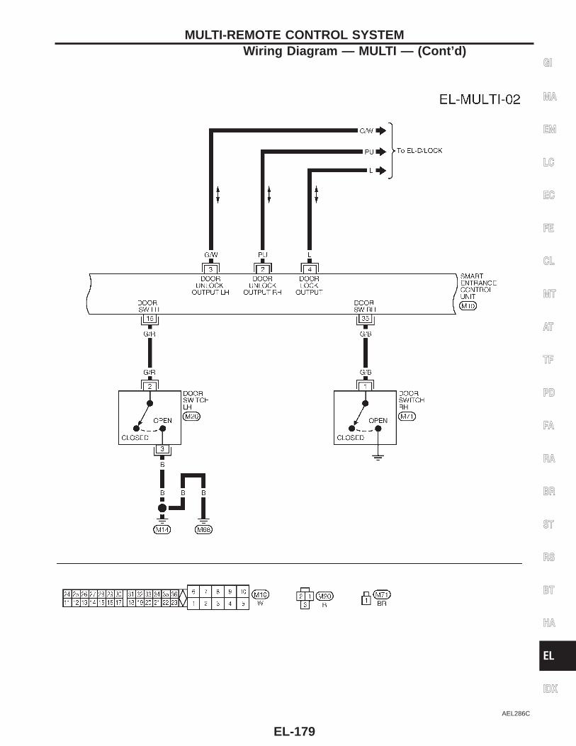
AEL286C
GI
MA
EM
LC
EC
FE
CL
MT
AT
TF
PD
FA
RA
BR
ST
RS
BT
HA
EL
IDX
MULTI-REMOTE CONTROL SYSTEMWiring Diagram — MULTI — (Cont’d)
EL-179
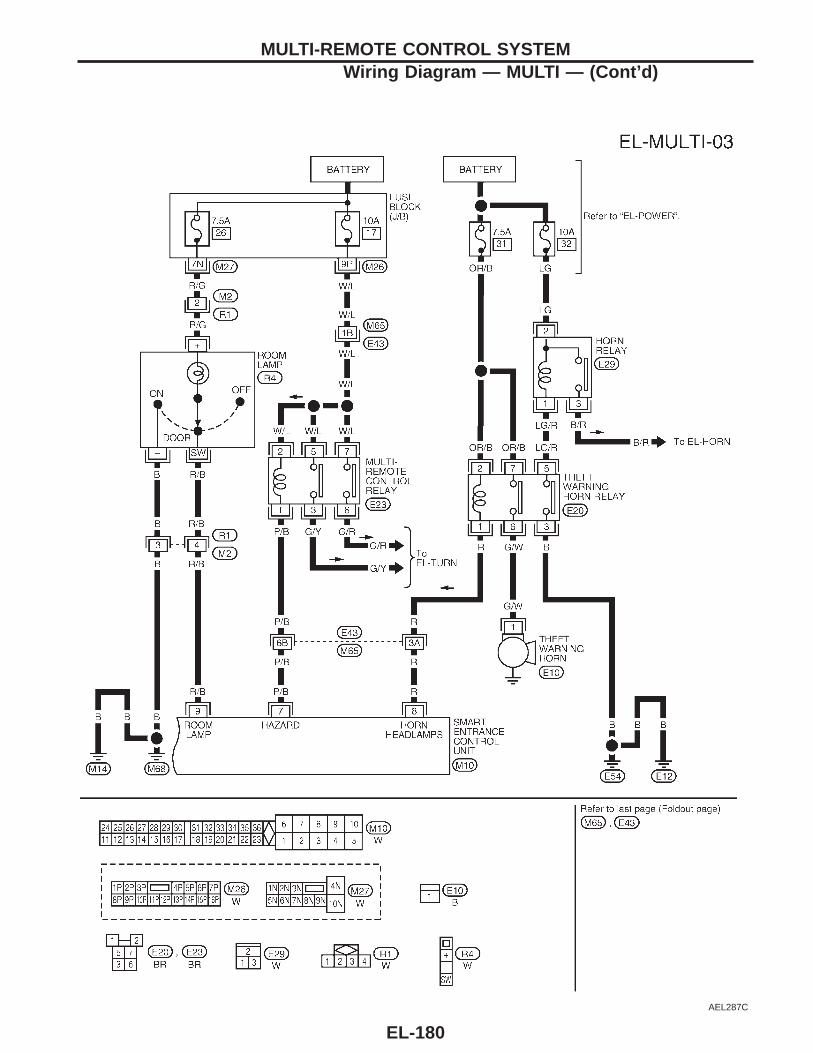
AEL287C
MULTI-REMOTE CONTROL SYSTEMWiring Diagram — MULTI — (Cont’d)
EL-180
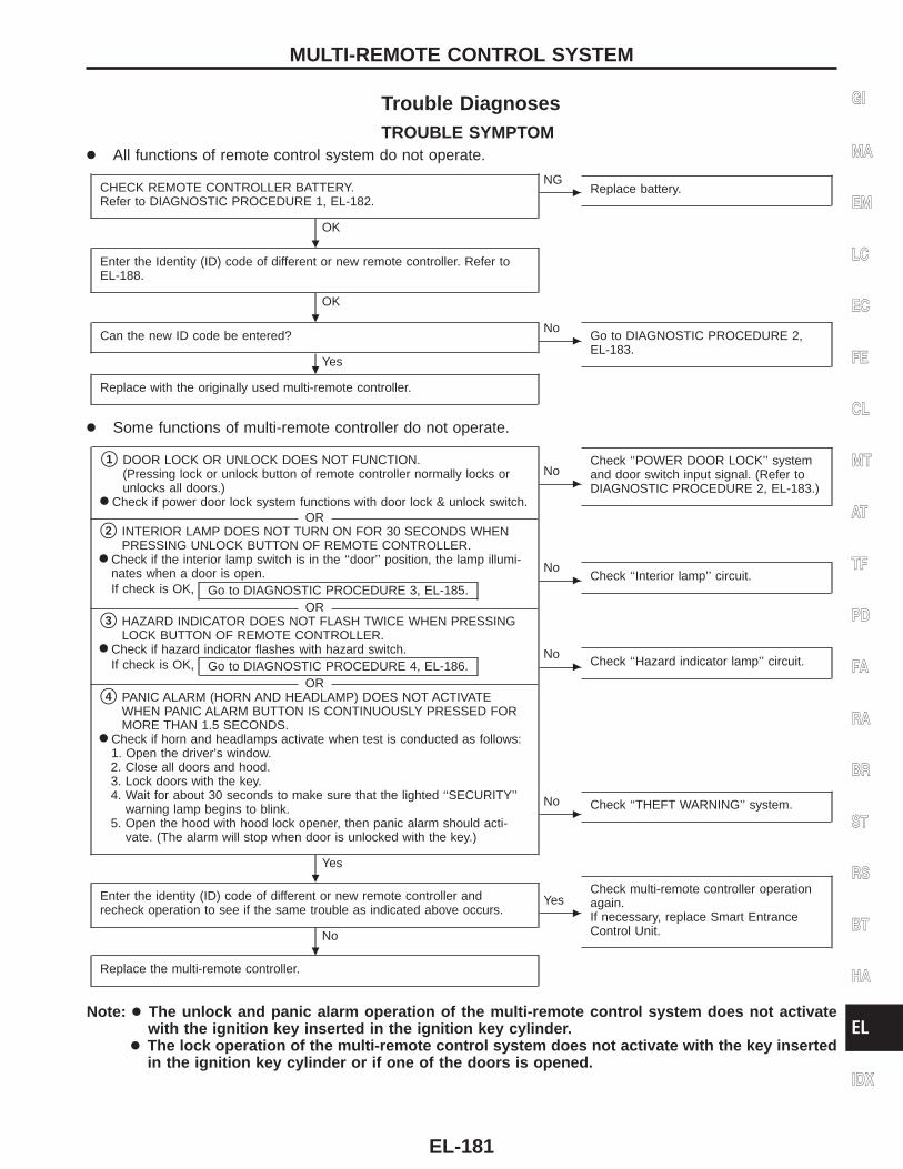
Trouble DiagnosesTROUBLE SYMPTOM
● All functions of remote control system do not operate.
CHECK REMOTE CONTROLLER BATTERY.Refer to DIAGNOSTIC PROCEDURE 1, EL-182.
OK
c
NGReplace battery.
Enter the Identity (ID) code of different or new remote controller. Refer toEL-188.
OK
Can the new ID code be entered?
Yes
c
NoGo to DIAGNOSTIC PROCEDURE 2,EL-183.
Replace with the originally used multi-remote controller.
● Some functions of multi-remote controller do not operate.
s1 DOOR LOCK OR UNLOCK DOES NOT FUNCTION.(Pressing lock or unlock button of remote controller normally locks orunlocks all doors.)
● Check if power door lock system functions with door lock & unlock switch.OR
s2 INTERIOR LAMP DOES NOT TURN ON FOR 30 SECONDS WHENPRESSING UNLOCK BUTTON OF REMOTE CONTROLLER.
● Check if the interior lamp switch is in the ‘‘door’’ position, the lamp illumi-nates when a door is open.If check is OK, Go to DIAGNOSTIC PROCEDURE 3, EL-185.
ORs3 HAZARD INDICATOR DOES NOT FLASH TWICE WHEN PRESSING
LOCK BUTTON OF REMOTE CONTROLLER.● Check if hazard indicator flashes with hazard switch.
If check is OK, Go to DIAGNOSTIC PROCEDURE 4, EL-186.OR
s4 PANIC ALARM (HORN AND HEADLAMP) DOES NOT ACTIVATEWHEN PANIC ALARM BUTTON IS CONTINUOUSLY PRESSED FORMORE THAN 1.5 SECONDS.
● Check if horn and headlamps activate when test is conducted as follows:1. Open the driver’s window.2. Close all doors and hood.3. Lock doors with the key.4. Wait for about 30 seconds to make sure that the lighted ‘‘SECURITY’’
warning lamp begins to blink.5. Open the hood with hood lock opener, then panic alarm should acti-
vate. (The alarm will stop when door is unlocked with the key.)
Yes
c
NoCheck ‘‘POWER DOOR LOCK’’ systemand door switch input signal. (Refer toDIAGNOSTIC PROCEDURE 2, EL-183.)
c
NoCheck ‘‘Interior lamp’’ circuit.
c
NoCheck ‘‘Hazard indicator lamp’’ circuit.
c
No Check ‘‘THEFT WARNING’’ system.
Enter the identity (ID) code of different or new remote controller andrecheck operation to see if the same trouble as indicated above occurs.
No
c
YesCheck multi-remote controller operationagain.If necessary, replace Smart EntranceControl Unit.
Replace the multi-remote controller.
Note: ● The unlock and panic alarm operation of the multi-remote control system does not activatewith the ignition key inserted in the ignition key cylinder.
● The lock operation of the multi-remote control system does not activate with the key insertedin the ignition key cylinder or if one of the doors is opened.
GI
MA
EM
LC
EC
FE
CL
MT
AT
TF
PD
FA
RA
BR
ST
RS
BT
HA
EL
IDX
MULTI-REMOTE CONTROL SYSTEM
.
.
.
.
.
EL-181
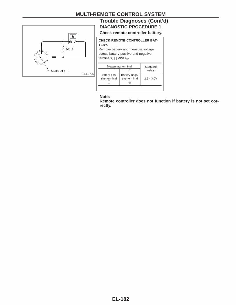
SEL672U
DIAGNOSTIC PROCEDURE 1Check remote controller battery.
CHECK REMOTE CONTROLLER BAT-TERY.Remove battery and measure voltageacross battery positive and negativeterminals, ⊕ and @.
Note:Remote controller does not function if battery is not set cor-rectly.
Measuring terminal Standardvalue⊕ @
Battery posi-tive terminal
⊕
Battery nega-tive terminal
@
2.5 - 3.0V
MULTI-REMOTE CONTROL SYSTEMTrouble Diagnoses (Cont’d)
EL-182
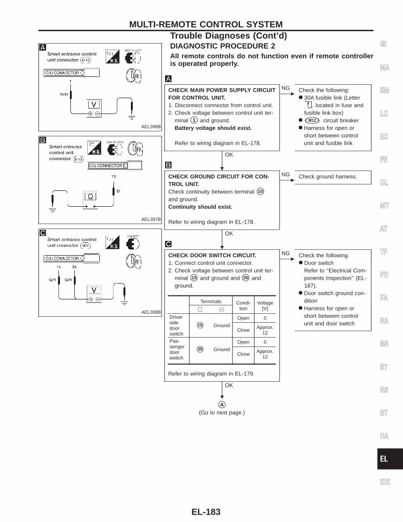
AEL396B
DIAGNOSTIC PROCEDURE 2All remote controls do not function even if remote controlleris operated properly.
AEL397B
AEL398B
CHECK MAIN POWER SUPPLY CIRCUITFOR CONTROL UNIT.1. Disconnect connector from control unit.2. Check voltage between control unit ter-
minal s1 and ground.Battery voltage should exist.
Refer to wiring diagram in EL-178.
OK
c
NG Check the following:● 30A fusible link (Letter
, located in fuse andfusible link box)
● sM12 circuit breaker● Harness for open or
short between controlunit and fusible link
CHECK GROUND CIRCUIT FOR CON-TROL UNIT.Check continuity between terminal s10
and ground.Continuity should exist.
Refer to wiring diagram in EL-178.
OK
c
NG Check ground harness.
CHECK DOOR SWITCH CIRCUIT.1. Connect control unit connector.2. Check voltage between control unit ter-
minal s15 and ground and s35 andground.
Refer to wiring diagram in EL-179.
OK
c
NG Check the following.● Door switch
Refer to ‘‘Electrical Com-ponents Inspection’’ (EL-187).
● Door switch ground con-dition
● Harness for open orshort between controlunit and door switch
sA(Go to next page.)
Terminals Condi-tion
Voltage[V]⊕ @
Driversidedoorswitch
s15 Ground
Open 0
Close Approx.12
Pas-sengerdoorswitch
s35 Ground
Open 0
Close Approx.12
GI
MA
EM
LC
EC
FE
CL
MT
AT
TF
PD
FA
RA
BR
ST
RS
BT
HA
EL
IDX
MULTI-REMOTE CONTROL SYSTEMTrouble Diagnoses (Cont’d)
.
.
.
EL-183
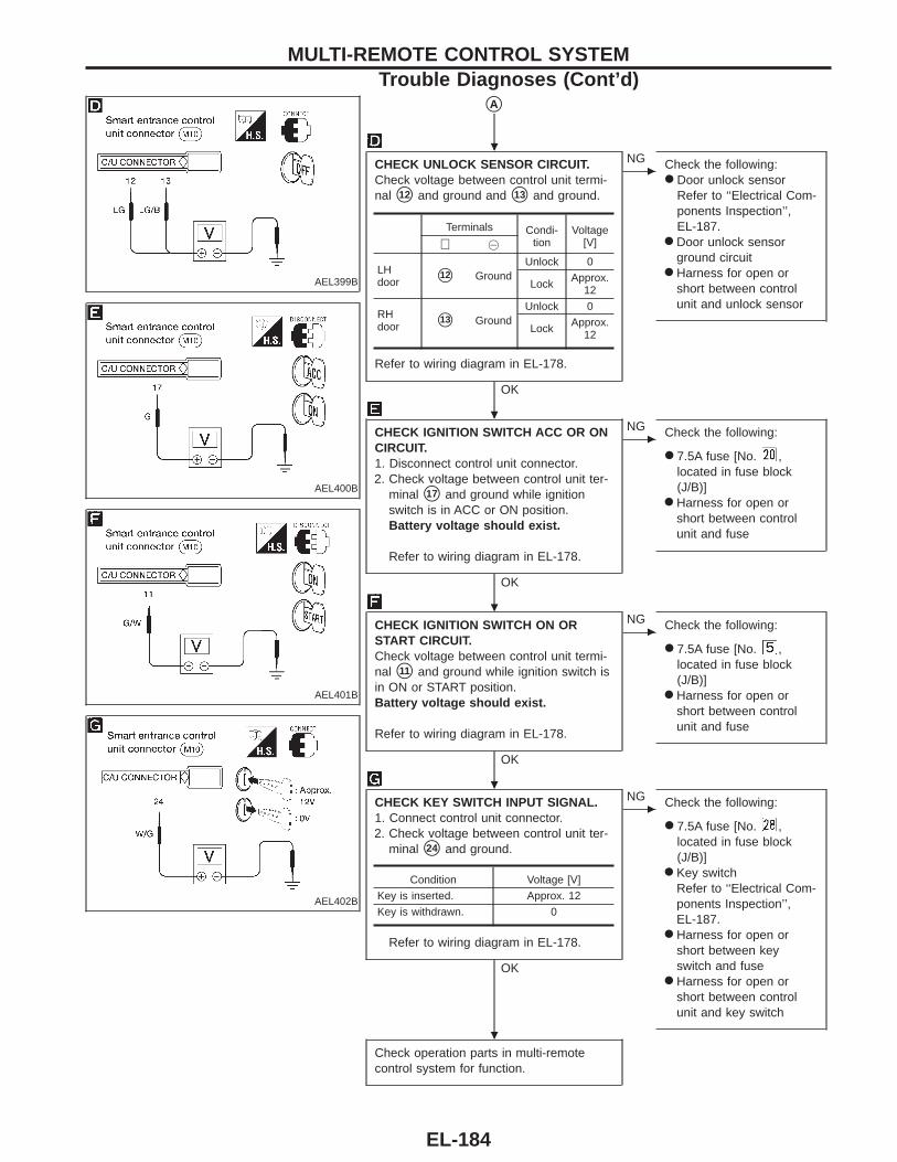
AEL399B
AEL400B
AEL401B
AEL402B
sA
CHECK UNLOCK SENSOR CIRCUIT.Check voltage between control unit termi-nal s12 and ground and s13 and ground.
Refer to wiring diagram in EL-178.
OK
c
NG Check the following:● Door unlock sensor
Refer to ‘‘Electrical Com-ponents Inspection’’,EL-187.
● Door unlock sensorground circuit
● Harness for open orshort between controlunit and unlock sensor
CHECK IGNITION SWITCH ACC OR ONCIRCUIT.1. Disconnect control unit connector.2. Check voltage between control unit ter-
minal s17 and ground while ignitionswitch is in ACC or ON position.Battery voltage should exist.
Refer to wiring diagram in EL-178.
OK
c
NG Check the following:
● 7.5A fuse [No. ,located in fuse block(J/B)]
● Harness for open orshort between controlunit and fuse
CHECK IGNITION SWITCH ON ORSTART CIRCUIT.Check voltage between control unit termi-nal s11 and ground while ignition switch isin ON or START position.Battery voltage should exist.
Refer to wiring diagram in EL-178.
OK
c
NG Check the following:
● 7.5A fuse [No. ,located in fuse block(J/B)]
● Harness for open orshort between controlunit and fuse
CHECK KEY SWITCH INPUT SIGNAL.1. Connect control unit connector.2. Check voltage between control unit ter-
minal s24 and ground.
Refer to wiring diagram in EL-178.
OK
c
NG Check the following:
● 7.5A fuse [No. ,located in fuse block(J/B)]
● Key switchRefer to ‘‘Electrical Com-ponents Inspection’’,EL-187.
● Harness for open orshort between keyswitch and fuse
● Harness for open orshort between controlunit and key switch
Check operation parts in multi-remotecontrol system for function.
Terminals Condi-tion
Voltage[V]⊕ @
LHdoor s12 Ground
Unlock 0
Lock Approx.12
RHdoor s13 Ground
Unlock 0
Lock Approx.12
Condition Voltage [V]
Key is inserted. Approx. 12
Key is withdrawn. 0
MULTI-REMOTE CONTROL SYSTEMTrouble Diagnoses (Cont’d)
.
.
.
.
.
EL-184
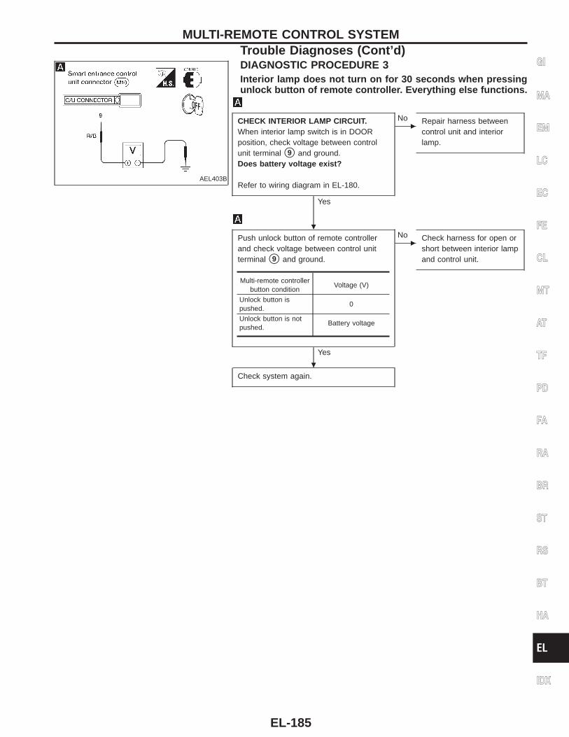
AEL403B
DIAGNOSTIC PROCEDURE 3Interior lamp does not turn on for 30 seconds when pressingunlock button of remote controller. Everything else functions.
CHECK INTERIOR LAMP CIRCUIT.When interior lamp switch is in DOORposition, check voltage between controlunit terminal s9 and ground.Does battery voltage exist?
Refer to wiring diagram in EL-180.
Yes
c
No Repair harness betweencontrol unit and interiorlamp.
Push unlock button of remote controllerand check voltage between control unitterminal s9 and ground.
Yes
c
No Check harness for open orshort between interior lampand control unit.
Check system again.
Multi-remote controllerbutton condition
Voltage (V)
Unlock button ispushed.
0
Unlock button is notpushed.
Battery voltage
GI
MA
EM
LC
EC
FE
CL
MT
AT
TF
PD
FA
RA
BR
ST
RS
BT
HA
EL
IDX
MULTI-REMOTE CONTROL SYSTEMTrouble Diagnoses (Cont’d)
.
.
EL-185
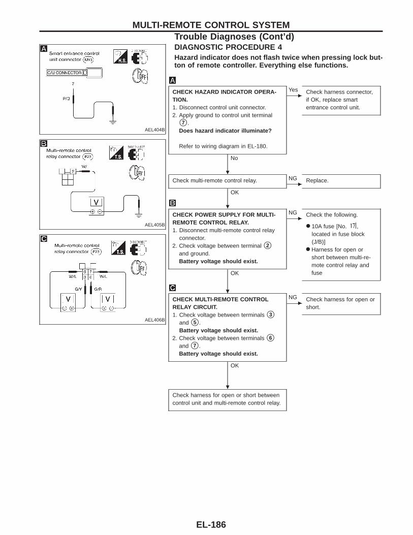
AEL404B
DIAGNOSTIC PROCEDURE 4Hazard indicator does not flash twice when pressing lock but-ton of remote controller. Everything else functions.
AEL405B
AEL406B
CHECK HAZARD INDICATOR OPERA-TION.1. Disconnect control unit connector.2. Apply ground to control unit terminal
s7 .Does hazard indicator illuminate?
Refer to wiring diagram in EL-180.
No
c
Yes Check harness connector,if OK, replace smartentrance control unit.
Check multi-remote control relay.
OKc
NG Replace.
CHECK POWER SUPPLY FOR MULTI-REMOTE CONTROL RELAY.1. Disconnect multi-remote control relay
connector.2. Check voltage between terminal s2
and ground.Battery voltage should exist.
OK
c
NG Check the following.
● 10A fuse [No. ,located in fuse block(J/B)]
● Harness for open orshort between multi-re-mote control relay andfuse
CHECK MULTI-REMOTE CONTROLRELAY CIRCUIT.1. Check voltage between terminals s3
and s5 .Battery voltage should exist.
2. Check voltage between terminals s6
and s7 .Battery voltage should exist.
OK
c
NG Check harness for open orshort.
Check harness for open or short betweencontrol unit and multi-remote control relay.
MULTI-REMOTE CONTROL SYSTEMTrouble Diagnoses (Cont’d)
.
.
.
.
EL-186
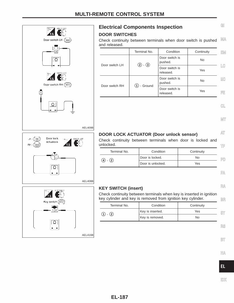
AEL409B
Electrical Components InspectionDOOR SWITCHESCheck continuity between terminals when door switch is pushedand released.
Terminal No. Condition Continuity
Door switch LH s2 - s3
Door switch ispushed.
No
Door switch isreleased.
Yes
Door switch RH s1 - Ground
Door switch ispushed.
No
Door switch isreleased.
Yes
AEL408B
DOOR LOCK ACTUATOR (Door unlock sensor)Check continuity between terminals when door is locked andunlocked.
Terminal No. Condition Continuity
s4 - s2Door is locked. No
Door is unlocked. Yes
AEL416B
KEY SWITCH (insert)Check continuity between terminals when key is inserted in ignitionkey cylinder and key is removed from ignition key cylinder.
Terminal No. Condition Continuity
s1 - s2Key is inserted. Yes
Key is removed. No
GI
MA
EM
LC
EC
FE
CL
MT
AT
TF
PD
FA
RA
BR
ST
RS
BT
HA
EL
IDX
MULTI-REMOTE CONTROL SYSTEM
EL-187
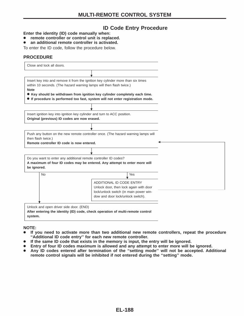
ID Code Entry ProcedureEnter the identity (ID) code manually when:● remote controller or control unit is replaced.● an additional remote controller is activated.To enter the ID code, follow the procedure below.
PROCEDURE
Close and lock all doors.
Insert key into and remove it from the ignition key cylinder more than six timeswithin 10 seconds. (The hazard warning lamps will then flash twice.)Note● Key should be withdrawn from ignition key cylinder completely each time.● If procedure is performed too fast, system will not enter registration mode.
Insert ignition key into ignition key cylinder and turn to ACC position.Original (previous) ID codes are now erased.
Push any button on the new remote controller once. (The hazard warning lamps willthen flash twice.)Remote controller ID code is now entered. b
Do you want to enter any additional remote controller ID codes?A maximum of four ID codes may be entered. Any attempt to enter more willbe ignored.
No Yes
ADDITIONAL ID CODE ENTRYUnlock door, then lock again with doorlock/unlock switch (in main power win-dow and door lock/unlock switch).
Unlock and open driver side door. (END)After entering the identity (ID) code, check operation of multi-remote controlsystem.
NOTE:● If you need to activate more than two additional new remote controllers, repeat the procedure
‘‘Additional ID code entry’’ for each new remote controller.● If the same ID code that exists in the memory is input, the entry will be ignored.● Entry of four ID codes maximum is allowed and any attempt to enter more will be ignored.● Any ID codes entered after termination of the ‘‘setting mode’’ will not be accepted. Additional
remote control signals will be inhibited if not entered during the ‘‘setting’’ mode.
MULTI-REMOTE CONTROL SYSTEM
.
.
.
.
.
.
EL-188
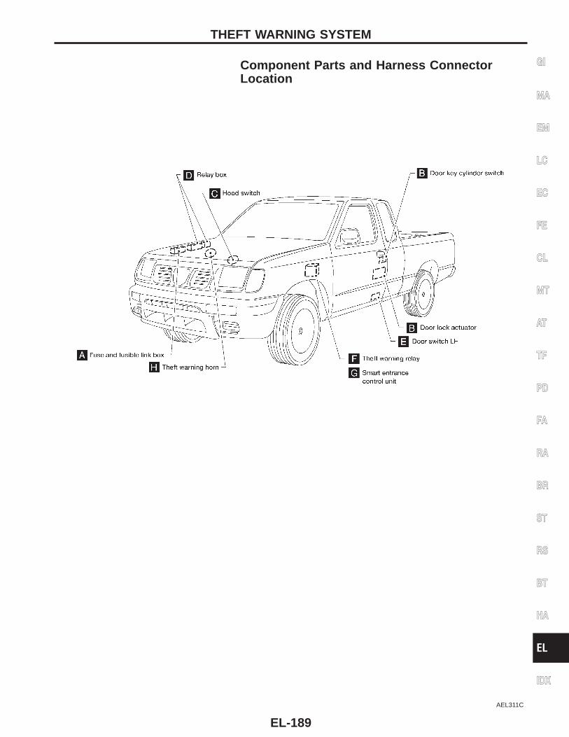
Component Parts and Harness ConnectorLocation
AEL311C
GI
MA
EM
LC
EC
FE
CL
MT
AT
TF
PD
FA
RA
BR
ST
RS
BT
HA
EL
IDX
THEFT WARNING SYSTEM
EL-189
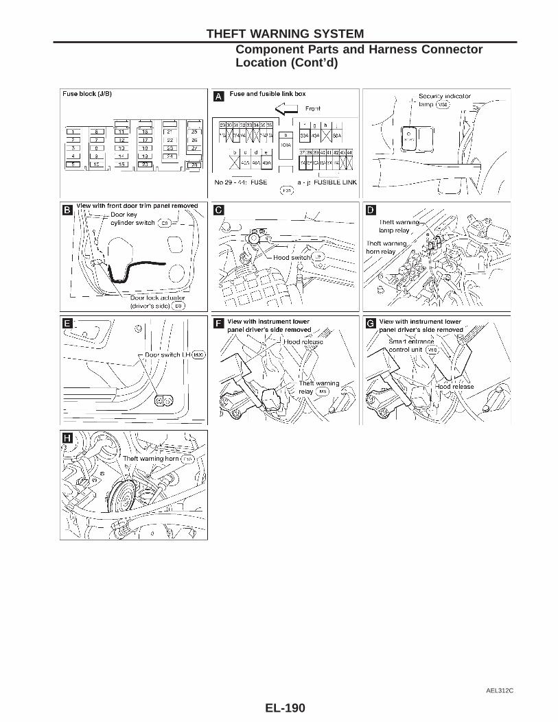
AEL312C
THEFT WARNING SYSTEMComponent Parts and Harness ConnectorLocation (Cont’d)
EL-190
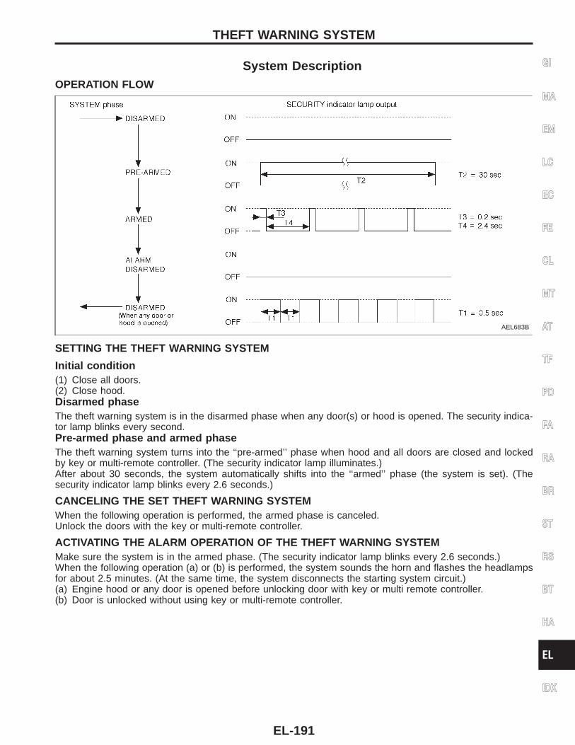
System DescriptionOPERATION FLOW
AEL683B
SETTING THE THEFT WARNING SYSTEM
Initial condition(1) Close all doors.(2) Close hood.Disarmed phaseThe theft warning system is in the disarmed phase when any door(s) or hood is opened. The security indica-tor lamp blinks every second.Pre-armed phase and armed phaseThe theft warning system turns into the ‘‘pre-armed’’ phase when hood and all doors are closed and lockedby key or multi-remote controller. (The security indicator lamp illuminates.)After about 30 seconds, the system automatically shifts into the ‘‘armed’’ phase (the system is set). (Thesecurity indicator lamp blinks every 2.6 seconds.)
CANCELING THE SET THEFT WARNING SYSTEMWhen the following operation is performed, the armed phase is canceled.Unlock the doors with the key or multi-remote controller.
ACTIVATING THE ALARM OPERATION OF THE THEFT WARNING SYSTEMMake sure the system is in the armed phase. (The security indicator lamp blinks every 2.6 seconds.)When the following operation (a) or (b) is performed, the system sounds the horn and flashes the headlampsfor about 2.5 minutes. (At the same time, the system disconnects the starting system circuit.)(a) Engine hood or any door is opened before unlocking door with key or multi remote controller.(b) Door is unlocked without using key or multi-remote controller.
GI
MA
EM
LC
EC
FE
CL
MT
AT
TF
PD
FA
RA
BR
ST
RS
BT
HA
EL
IDX
THEFT WARNING SYSTEM
EL-191
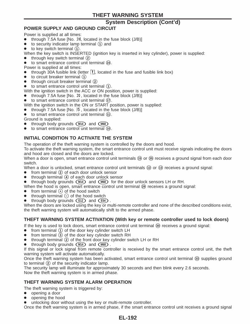
POWER SUPPLY AND GROUND CIRCUITPower is supplied at all times:● through 7.5A fuse [No. , located in the fuse block (J/B)]● to security indicator lamp terminal s1 and● to key switch terminal s1 .When the key switch is INSERTED (ignition key is inserted in key cylinder), power is supplied:● through key switch terminal s2● to smart entrance control unit terminal s24 .Power is supplied at all times:● through 30A fusible link (letter , located in the fuse and fusible link box)● to circuit breaker terminal s1● through circuit breaker terminal s2● to smart entrance control unit terminal s1 .With the ignition switch in the ACC or ON position, power is supplied:● through 7.5A fuse [No. , located in the fuse block (J/B)]● to smart entrance control unit terminal s17 .With the ignition switch in the ON or START position, power is supplied:● through 7.5A fuse [No. , located in the fuse block (J/B)]● to smart entrance control unit terminal s11 .Ground is supplied:● through body grounds sM14 and sM68● to smart entrance control unit terminal s10 .
INITIAL CONDITION TO ACTIVATE THE SYSTEMThe operation of the theft warning system is controlled by the doors and hood.To activate the theft warning system, the smart entrance control unit must receive signals indicating the doorsand hood are closed and the doors are locked.When a door is open, smart entrance control unit terminals s15 or s35 receives a ground signal from each doorswitch.When a door is unlocked, smart entrance control unit terminals s12 or s13 receives a ground signal:● from terminal s2 of each door unlock sensor● through terminal s4 of each door unlock sensor● through body grounds sM14 and sM68 for the door unlock sensors LH or RH.When the hood is open, smart entrance control unit terminal s29 receives a ground signal:● from terminal s+ of the hood switch● through terminal s− of the hood switch● through body grounds sE12 and sE54 .When the doors are locked using the key or multi-remote controller and none of the described conditions exist,the theft warning system will automatically shift to the armed phase.
THEFT WARNING SYSTEM ACTIVATION (With key or remote controller used to lock doors)If the key is used to lock doors, smart entrance control unit terminal s30 receives a ground signal:● from terminal s1 of the door key cylinder switch LH● from terminal s3 of the door key cylinder switch RH● through terminal s2 of the front door key cylinder switch LH or RH● through body grounds sM14 and sM68 .If this signal or lock signal from remote controller is received by the smart entrance control unit, the theftwarning system will activate automatically.Once the theft warning system has been activated, smart entrance control unit terminal s33 supplies groundto terminal s2 of the security indicator lamp.The security lamp will illuminate for approximately 30 seconds and then blink every 2.6 seconds.Now the theft warning system is in armed phase.
THEFT WARNING SYSTEM ALARM OPERATIONThe theft warning system is triggered by:● opening a door● opening the hood● unlocking door without using the key or multi-remote controller.Once the theft warning system is in armed phase, if the smart entrance control unit receives a ground signal
THEFT WARNING SYSTEMSystem Description (Cont’d)
EL-192
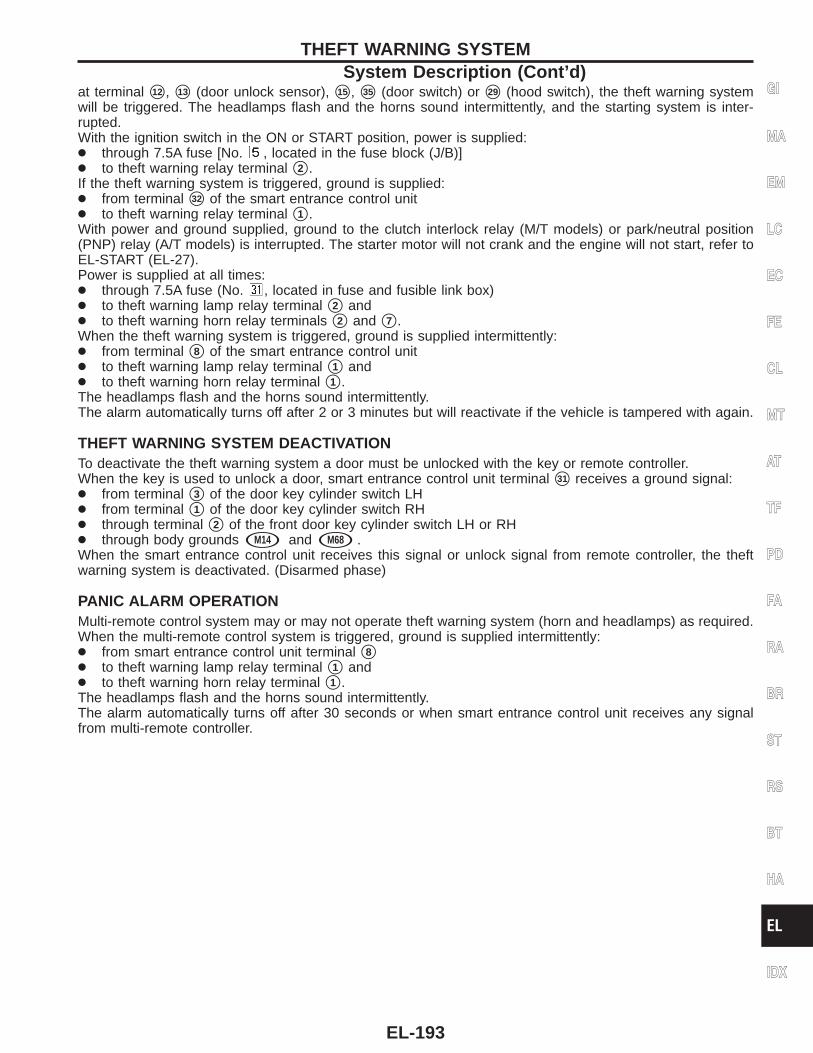
at terminal s12 , s13 (door unlock sensor), s15 , s35 (door switch) or s29 (hood switch), the theft warning systemwill be triggered. The headlamps flash and the horns sound intermittently, and the starting system is inter-rupted.With the ignition switch in the ON or START position, power is supplied:● through 7.5A fuse [No. , located in the fuse block (J/B)]● to theft warning relay terminal s2 .If the theft warning system is triggered, ground is supplied:● from terminal s32 of the smart entrance control unit● to theft warning relay terminal s1 .With power and ground supplied, ground to the clutch interlock relay (M/T models) or park/neutral position(PNP) relay (A/T models) is interrupted. The starter motor will not crank and the engine will not start, refer toEL-START (EL-27).Power is supplied at all times:● through 7.5A fuse (No. , located in fuse and fusible link box)● to theft warning lamp relay terminal s2 and● to theft warning horn relay terminals s2 and s7 .When the theft warning system is triggered, ground is supplied intermittently:● from terminal s8 of the smart entrance control unit● to theft warning lamp relay terminal s1 and● to theft warning horn relay terminal s1 .The headlamps flash and the horns sound intermittently.The alarm automatically turns off after 2 or 3 minutes but will reactivate if the vehicle is tampered with again.
THEFT WARNING SYSTEM DEACTIVATIONTo deactivate the theft warning system a door must be unlocked with the key or remote controller.When the key is used to unlock a door, smart entrance control unit terminal s31 receives a ground signal:● from terminal s3 of the door key cylinder switch LH● from terminal s1 of the door key cylinder switch RH● through terminal s2 of the front door key cylinder switch LH or RH● through body grounds sM14 and sM68 .When the smart entrance control unit receives this signal or unlock signal from remote controller, the theftwarning system is deactivated. (Disarmed phase)
PANIC ALARM OPERATIONMulti-remote control system may or may not operate theft warning system (horn and headlamps) as required.When the multi-remote control system is triggered, ground is supplied intermittently:● from smart entrance control unit terminal s8● to theft warning lamp relay terminal s1 and● to theft warning horn relay terminal s1 .The headlamps flash and the horns sound intermittently.The alarm automatically turns off after 30 seconds or when smart entrance control unit receives any signalfrom multi-remote controller.
GI
MA
EM
LC
EC
FE
CL
MT
AT
TF
PD
FA
RA
BR
ST
RS
BT
HA
EL
IDX
THEFT WARNING SYSTEMSystem Description (Cont’d)
EL-193
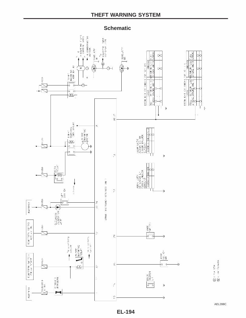
Schematic
AEL288C
THEFT WARNING SYSTEM
EL-194
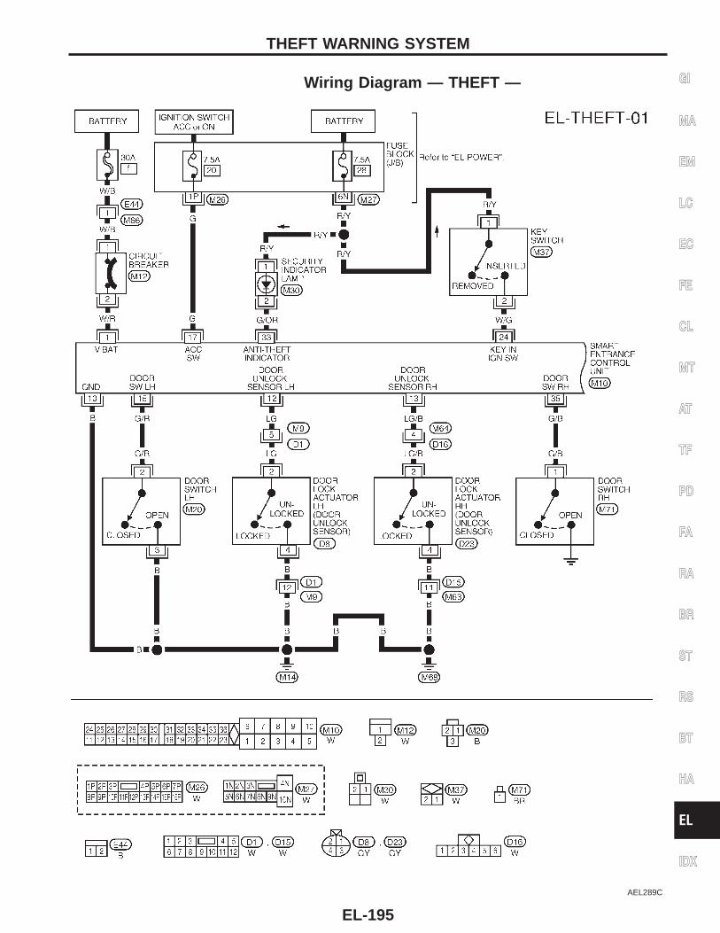
Wiring Diagram — THEFT —
AEL289C
GI
MA
EM
LC
EC
FE
CL
MT
AT
TF
PD
FA
RA
BR
ST
RS
BT
HA
EL
IDX
THEFT WARNING SYSTEM
EL-195
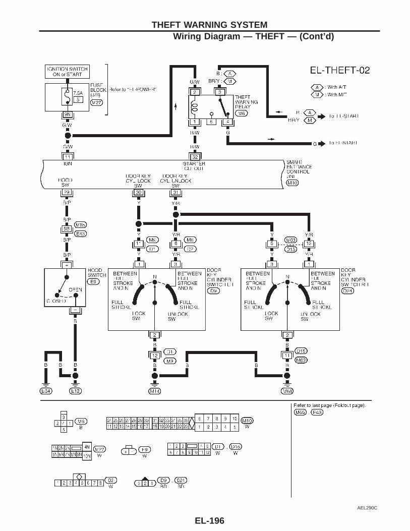
AEL290C
THEFT WARNING SYSTEMWiring Diagram — THEFT — (Cont’d)
EL-196
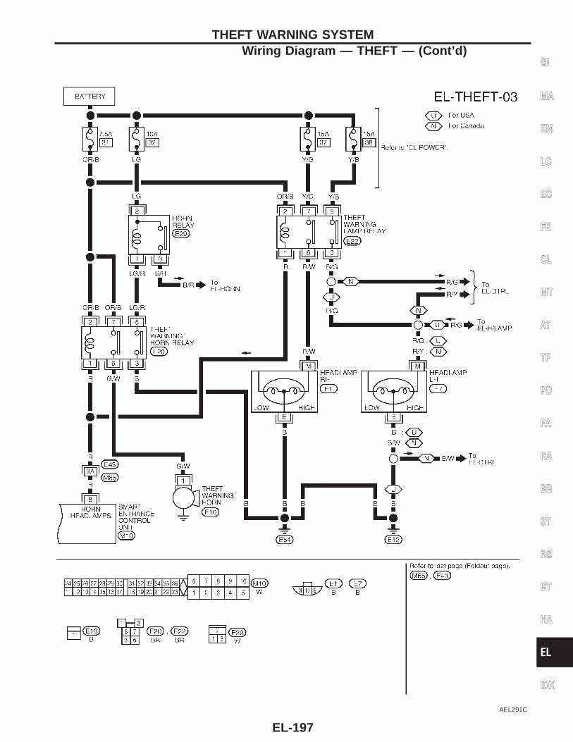
AEL291C
GI
MA
EM
LC
EC
FE
CL
MT
AT
TF
PD
FA
RA
BR
ST
RS
BT
HA
EL
IDX
THEFT WARNING SYSTEMWiring Diagram — THEFT — (Cont’d)
EL-197
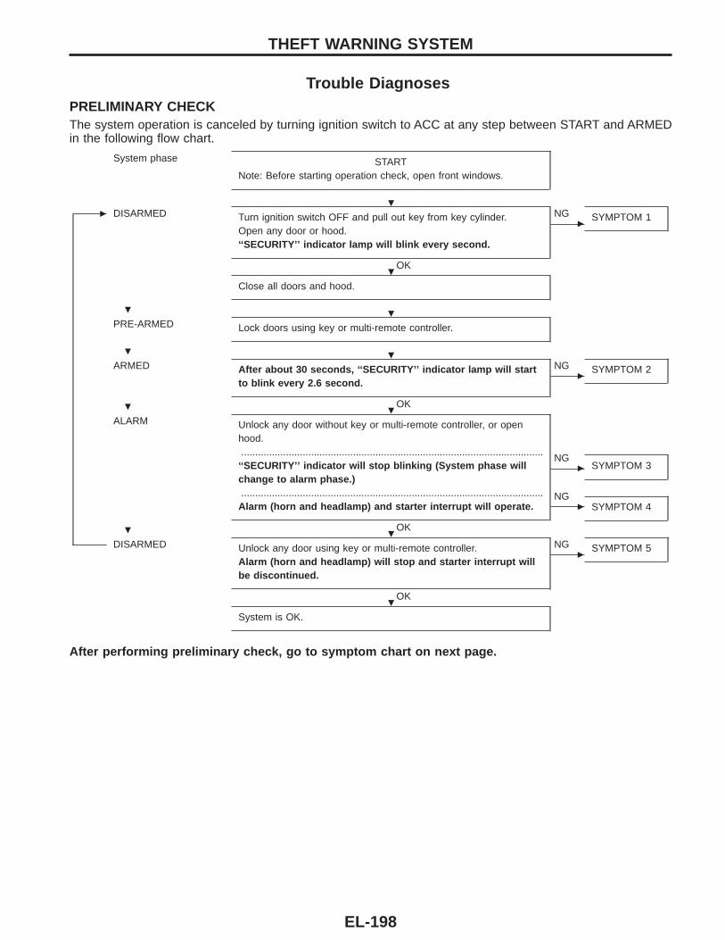
Trouble DiagnosesPRELIMINARY CHECKThe system operation is canceled by turning ignition switch to ACC at any step between START and ARMEDin the following flow chart.
System phase STARTNote: Before starting operation check, open front windows.
c DISARMED Turn ignition switch OFF and pull out key from key cylinder.Open any door or hood.‘‘SECURITY’’ indicator lamp will blink every second.
OK
c
NG SYMPTOM 1
Close all doors and hood.
PRE-ARMED Lock doors using key or multi-remote controller.
ARMED After about 30 seconds, ‘‘SECURITY’’ indicator lamp will startto blink every 2.6 second.
OK
c
NG SYMPTOM 2
ALARM Unlock any door without key or multi-remote controller, or openhood.............................................................................................................‘‘SECURITY’’ indicator will stop blinking (System phase willchange to alarm phase.)............................................................................................................Alarm (horn and headlamp) and starter interrupt will operate.
OK
c
NGSYMPTOM 3
c
NGSYMPTOM 4
DISARMED Unlock any door using key or multi-remote controller.Alarm (horn and headlamp) will stop and starter interrupt willbe discontinued.
OK
c
NG SYMPTOM 5
System is OK.
After performing preliminary check, go to symptom chart on next page.
THEFT WARNING SYSTEM
.
.
. .
. .
. .
. .
.
EL-198
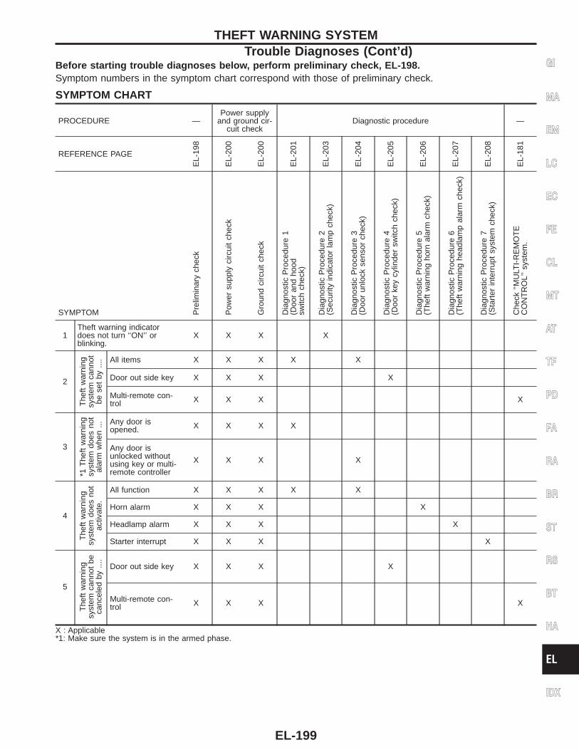
Before starting trouble diagnoses below, perform preliminary check, EL-198.Symptom numbers in the symptom chart correspond with those of preliminary check.
SYMPTOM CHART
PROCEDURE —Power supply
and ground cir-cuit check
Diagnostic procedure —
REFERENCE PAGE
EL-
198
EL-
200
EL-
200
EL-
201
EL-
203
EL-
204
EL-
205
EL-
206
EL-
207
EL-
208
EL-
181
SYMPTOM Pre
limin
ary
chec
k
Pow
ersu
pply
circ
uit
chec
k
Gro
und
circ
uit
chec
k
Dia
gnos
ticP
roce
dure
1(D
oor
and
hood
switc
hch
eck)
Dia
gnos
ticP
roce
dure
2(S
ecur
ityin
dica
tor
lam
pch
eck)
Dia
gnos
ticP
roce
dure
3(D
oor
unlo
ckse
nsor
chec
k)
Dia
gnos
ticP
roce
dure
4(D
oor
key
cylin
der
switc
hch
eck)
Dia
gnos
ticP
roce
dure
5(T
heft
war
ning
horn
alar
mch
eck)
Dia
gnos
ticP
roce
dure
6(T
heft
war
ning
head
lam
pal
arm
chec
k)
Dia
gnos
ticP
roce
dure
7(S
tart
erin
terr
upt
syst
emch
eck)
Che
ck‘‘M
ULT
I-R
EM
OT
EC
ON
TR
OL’
’sys
tem
.
1Theft warning indicatordoes not turn ‘‘ON’’ orblinking.
X X X X
2
The
ftw
arni
ngsy
stem
cann
otbe
set
by...
. All items X X X X X
Door out side key X X X X
Multi-remote con-trol X X X X
3
*1T
heft
war
ning
syst
emdo
esno
tal
arm
whe
n... Any door is
opened. X X X X
Any door isunlocked withoutusing key or multi-remote controller
X X X X
4
The
ftw
arni
ngsy
stem
does
not
activ
ate.
All function X X X X X
Horn alarm X X X X
Headlamp alarm X X X X
Starter interrupt X X X X
5
The
ftw
arni
ngsy
stem
cann
otbe
canc
eled
by...
.
Door out side key X X X X
Multi-remote con-trol X X X X
X : Applicable*1: Make sure the system is in the armed phase.
GI
MA
EM
LC
EC
FE
CL
MT
AT
TF
PD
FA
RA
BR
ST
RS
BT
HA
EL
IDX
THEFT WARNING SYSTEMTrouble Diagnoses (Cont’d)
EL-199
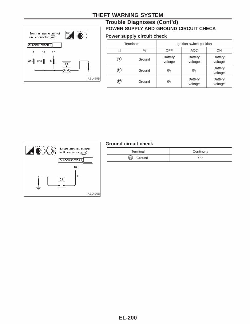
AEL425B
POWER SUPPLY AND GROUND CIRCUIT CHECK
Power supply circuit check
Terminals Ignition switch position
⊕ @ OFF ACC ON
s1 GroundBatteryvoltage
Batteryvoltage
Batteryvoltage
s11 Ground 0V 0VBatteryvoltage
s17 Ground 0VBatteryvoltage
Batteryvoltage
AEL426B
Ground circuit check
Terminal Continuity
s10 - Ground Yes
THEFT WARNING SYSTEMTrouble Diagnoses (Cont’d)
EL-200
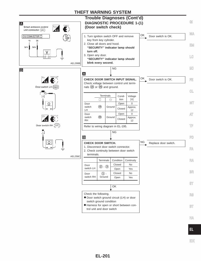
AEL398B
DIAGNOSTIC PROCEDURE 1-(1)(Door switch check)
AEL258C
1. Turn ignition switch OFF and removekey from key cylinder.
2. Close all doors and hood.‘‘SECURITY’’ indicator lamp shouldturn off.
3. Open any door.‘‘SECURITY’’ indicator lamp shouldblink every second.
NG
c
OK Door switch is OK.
CHECK DOOR SWITCH INPUT SIGNAL.Check voltage between control unit termi-nals s15 or s35 and ground.
Refer to wiring diagram in EL-195.
NG
c
OK Door switch is OK.
CHECK DOOR SWITCH.1. Disconnect door switch connector.2. Check continuity between door switch
terminals.
OK
c
NG Replace door switch.
Check the following.● Door switch ground circuit (LH) or door
switch ground condition● Harness for open or short between con-
trol unit and door switch
Terminals Condi-tion
Voltage[V]⊕ @
DoorswitchLH
s15 GroundOpen 0
ClosedApprox.
12
DoorswitchRH
s35 GroundOpen 0
ClosedApprox.
12
Terminals Condition Continuity
Doorswitch LH s2 - s3
Closed No
Open Yes
Doorswitch RH
s1 -Ground
Closed No
Open Yes
GI
MA
EM
LC
EC
FE
CL
MT
AT
TF
PD
FA
RA
BR
ST
RS
BT
HA
EL
IDX
THEFT WARNING SYSTEMTrouble Diagnoses (Cont’d)
.
.
.
EL-201
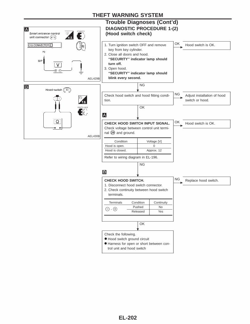
AEL429B
DIAGNOSTIC PROCEDURE 1-(2)(Hood switch check)
AEL430B
1. Turn ignition switch OFF and removekey from key cylinder.
2. Close all doors and hood.‘‘SECURITY’’ indicator lamp shouldturn off.
3. Open hood.‘‘SECURITY’’ indicator lamp shouldblink every second.
NG
c
OK Hood switch is OK.
Check hood switch and hood fitting condi-tion.
OK
c
NG Adjust installation of hoodswitch or hood.
CHECK HOOD SWITCH INPUT SIGNAL.Check voltage between control unit termi-nal s29 and ground.
Refer to wiring diagram in EL-196.
NG
c
OK Hood switch is OK.
CHECK HOOD SWITCH.1. Disconnect hood switch connector.2. Check continuity between hood switch
terminals.
OK
c
NG Replace hood switch.
Check the following.● Hood switch ground circuit● Harness for open or short between con-
trol unit and hood switch
Condition Voltage [V]
Hood is open. 0
Hood is closed. Approx. 12
Terminals Condition Continuity
s− - s+Pushed No
Released Yes
THEFT WARNING SYSTEMTrouble Diagnoses (Cont’d)
.
.
.
.
EL-202
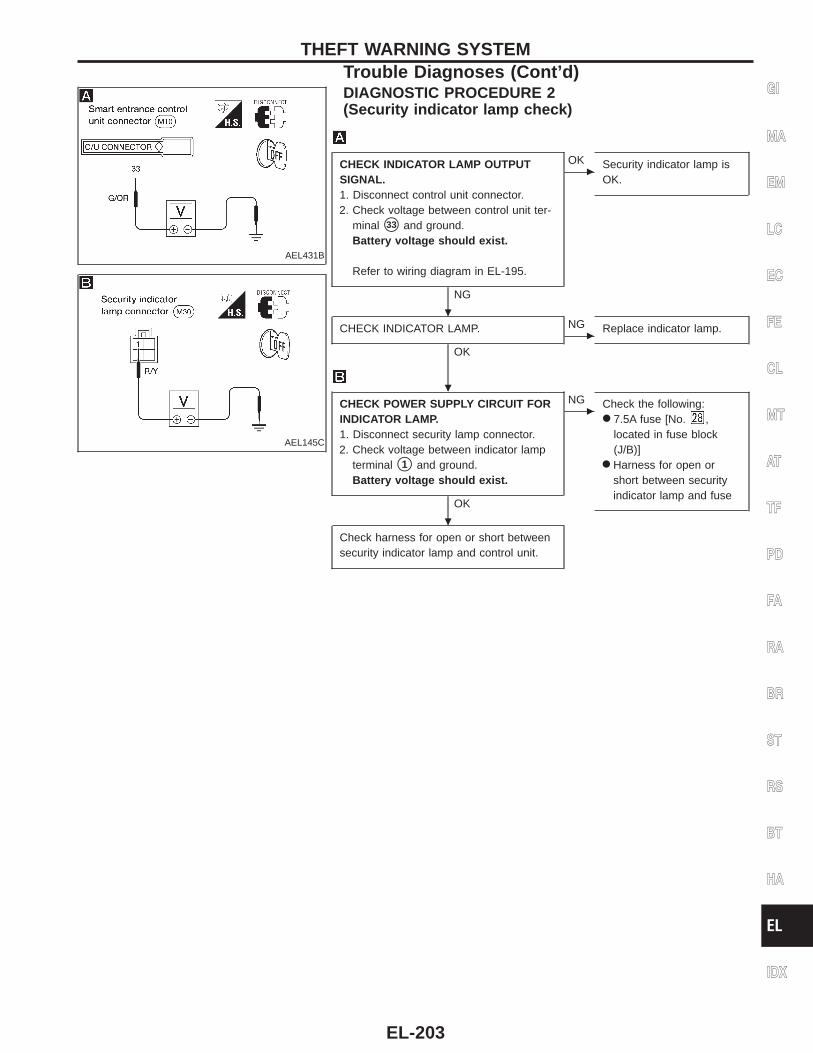
AEL431B
DIAGNOSTIC PROCEDURE 2(Security indicator lamp check)
AEL145C
CHECK INDICATOR LAMP OUTPUTSIGNAL.1. Disconnect control unit connector.2. Check voltage between control unit ter-
minal s33 and ground.Battery voltage should exist.
Refer to wiring diagram in EL-195.
NG
c
OK Security indicator lamp isOK.
CHECK INDICATOR LAMP.
OKc
NG Replace indicator lamp.
CHECK POWER SUPPLY CIRCUIT FORINDICATOR LAMP.1. Disconnect security lamp connector.2. Check voltage between indicator lamp
terminal s1 and ground.Battery voltage should exist.
OK
c
NG Check the following:● 7.5A fuse [No. ,
located in fuse block(J/B)]
● Harness for open orshort between securityindicator lamp and fuse
Check harness for open or short betweensecurity indicator lamp and control unit.
GI
MA
EM
LC
EC
FE
CL
MT
AT
TF
PD
FA
RA
BR
ST
RS
BT
HA
EL
IDX
THEFT WARNING SYSTEMTrouble Diagnoses (Cont’d)
.
.
.
EL-203
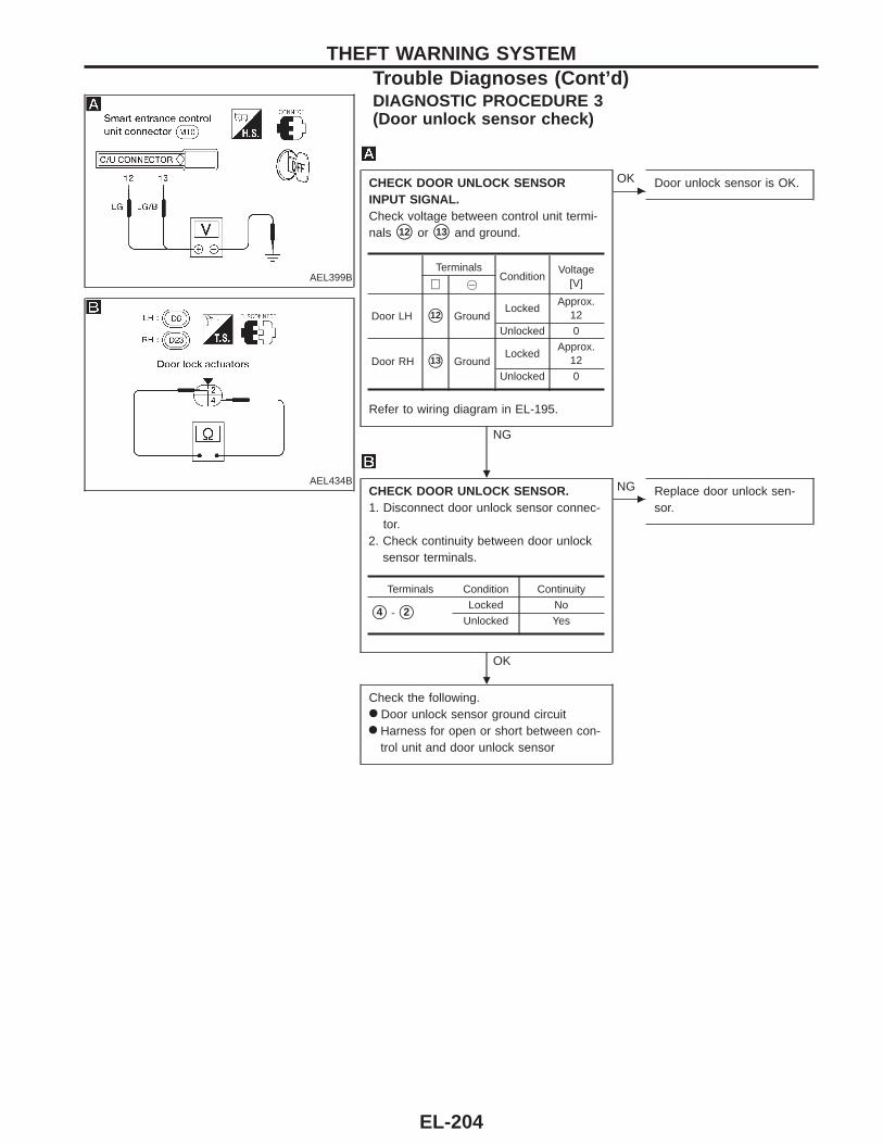
AEL399B
DIAGNOSTIC PROCEDURE 3(Door unlock sensor check)
AEL434B
CHECK DOOR UNLOCK SENSORINPUT SIGNAL.Check voltage between control unit termi-nals s12 or s13 and ground.
Refer to wiring diagram in EL-195.
NG
c
OK Door unlock sensor is OK.
CHECK DOOR UNLOCK SENSOR.1. Disconnect door unlock sensor connec-
tor.2. Check continuity between door unlock
sensor terminals.
OK
c
NG Replace door unlock sen-sor.
Check the following.● Door unlock sensor ground circuit● Harness for open or short between con-
trol unit and door unlock sensor
TerminalsCondition
Voltage[V]⊕ @
Door LH s12 GroundLocked
Approx.12
Unlocked 0
Door RH s13 GroundLocked
Approx.12
Unlocked 0
Terminals Condition Continuity
s4 - s2Locked No
Unlocked Yes
THEFT WARNING SYSTEMTrouble Diagnoses (Cont’d)
.
.
EL-204
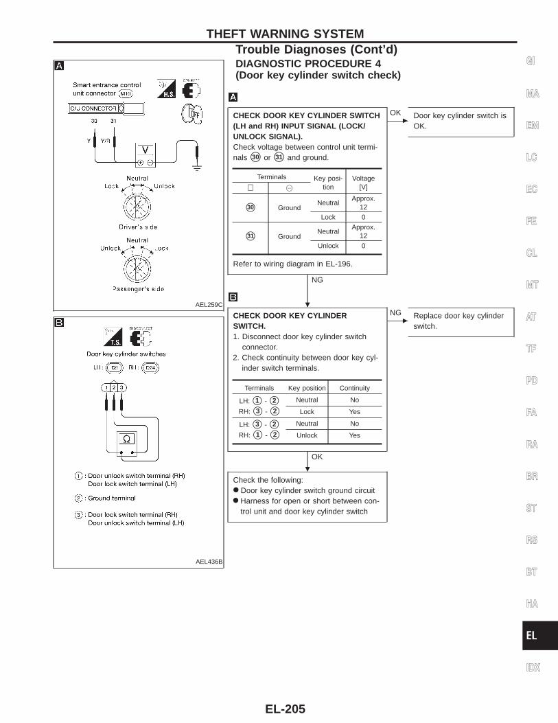
AEL259C
DIAGNOSTIC PROCEDURE 4(Door key cylinder switch check)
AEL436B
CHECK DOOR KEY CYLINDER SWITCH(LH and RH) INPUT SIGNAL (LOCK/UNLOCK SIGNAL).Check voltage between control unit termi-nals s30 or s31 and ground.
Refer to wiring diagram in EL-196.
NG
c
OK Door key cylinder switch isOK.
CHECK DOOR KEY CYLINDERSWITCH.1. Disconnect door key cylinder switch
connector.2. Check continuity between door key cyl-
inder switch terminals.
OK
c
NG Replace door key cylinderswitch.
Check the following:● Door key cylinder switch ground circuit● Harness for open or short between con-
trol unit and door key cylinder switch
Terminals Key posi-tion
Voltage[V]⊕ @
s30 GroundNeutral
Approx.12
Lock 0
s31 GroundNeutral
Approx.12
Unlock 0
Terminals Key position Continuity
LH: s1 - s2
RH: s3 - s2
Neutral No
Lock Yes
LH: s3 - s2
RH: s1 - s2
Neutral No
Unlock Yes
GI
MA
EM
LC
EC
FE
CL
MT
AT
TF
PD
FA
RA
BR
ST
RS
BT
HA
EL
IDX
THEFT WARNING SYSTEMTrouble Diagnoses (Cont’d)
.
.
EL-205
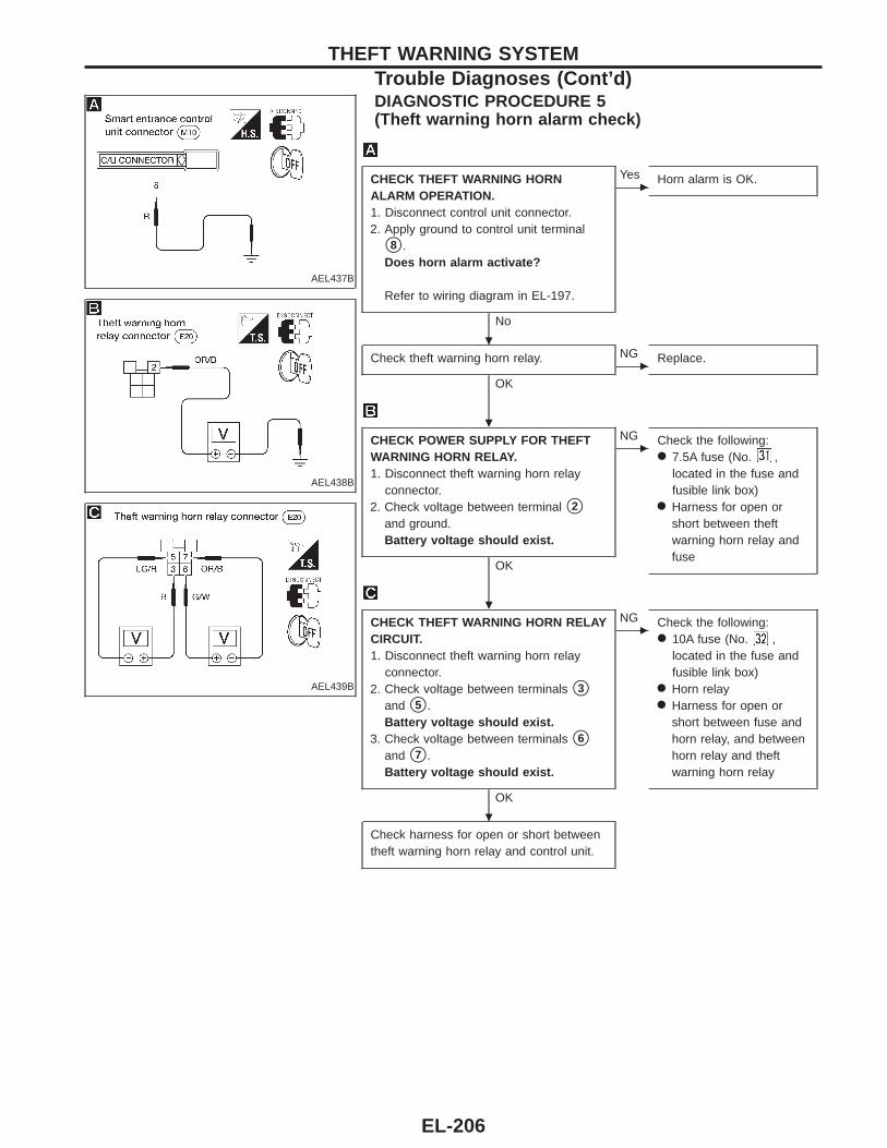
AEL437B
DIAGNOSTIC PROCEDURE 5(Theft warning horn alarm check)
AEL438B
AEL439B
CHECK THEFT WARNING HORNALARM OPERATION.1. Disconnect control unit connector.2. Apply ground to control unit terminal
s8 .Does horn alarm activate?
Refer to wiring diagram in EL-197.
No
c
Yes Horn alarm is OK.
Check theft warning horn relay.
OKc
NG Replace.
CHECK POWER SUPPLY FOR THEFTWARNING HORN RELAY.1. Disconnect theft warning horn relay
connector.2. Check voltage between terminal s2
and ground.Battery voltage should exist.
OK
c
NG Check the following:● 7.5A fuse (No. ,
located in the fuse andfusible link box)
● Harness for open orshort between theftwarning horn relay andfuse
CHECK THEFT WARNING HORN RELAYCIRCUIT.1. Disconnect theft warning horn relay
connector.2. Check voltage between terminals s3
and s5 .Battery voltage should exist.
3. Check voltage between terminals s6
and s7 .Battery voltage should exist.
OK
c
NG Check the following:● 10A fuse (No. ,
located in the fuse andfusible link box)
● Horn relay● Harness for open or
short between fuse andhorn relay, and betweenhorn relay and theftwarning horn relay
Check harness for open or short betweentheft warning horn relay and control unit.
THEFT WARNING SYSTEMTrouble Diagnoses (Cont’d)
.
.
.
.
EL-206
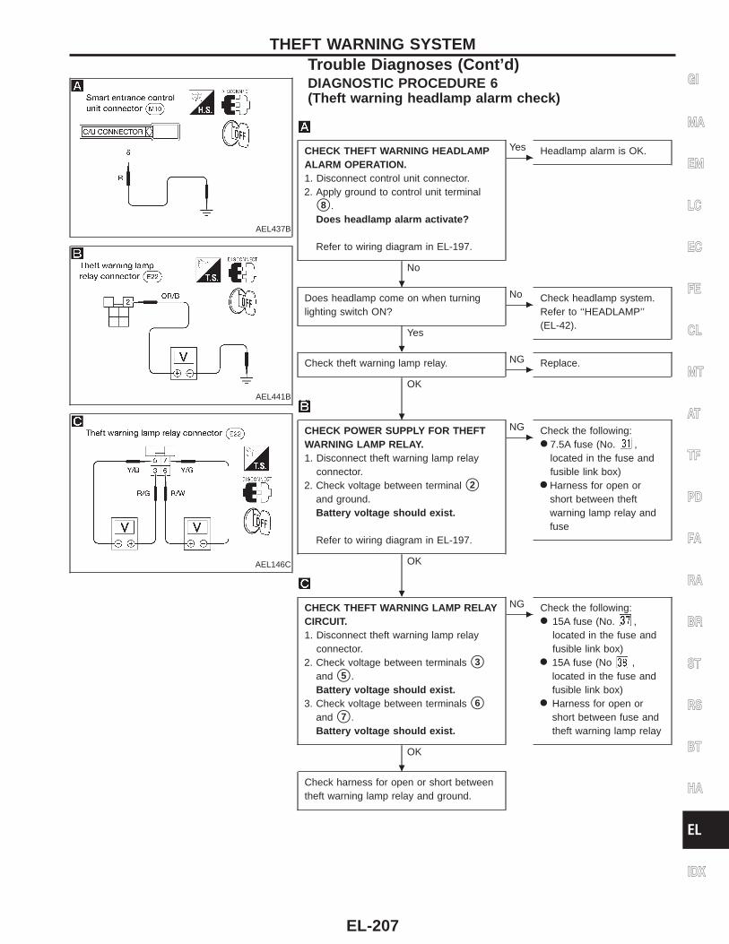
AEL437B
DIAGNOSTIC PROCEDURE 6(Theft warning headlamp alarm check)
AEL441B
AEL146C
CHECK THEFT WARNING HEADLAMPALARM OPERATION.1. Disconnect control unit connector.2. Apply ground to control unit terminal
s8 .Does headlamp alarm activate?
Refer to wiring diagram in EL-197.
No
c
Yes Headlamp alarm is OK.
Does headlamp come on when turninglighting switch ON?
Yes
c
No Check headlamp system.Refer to ‘‘HEADLAMP’’(EL-42).
Check theft warning lamp relay.
OKc
NG Replace.
CHECK POWER SUPPLY FOR THEFTWARNING LAMP RELAY.1. Disconnect theft warning lamp relay
connector.2. Check voltage between terminal s2
and ground.Battery voltage should exist.
Refer to wiring diagram in EL-197.
OK
c
NG Check the following:● 7.5A fuse (No. ,
located in the fuse andfusible link box)
● Harness for open orshort between theftwarning lamp relay andfuse
CHECK THEFT WARNING LAMP RELAYCIRCUIT.1. Disconnect theft warning lamp relay
connector.2. Check voltage between terminals s3
and s5 .Battery voltage should exist.
3. Check voltage between terminals s6
and s7 .Battery voltage should exist.
OK
c
NG Check the following:● 15A fuse (No. ,
located in the fuse andfusible link box)
● 15A fuse (No ,located in the fuse andfusible link box)
● Harness for open orshort between fuse andtheft warning lamp relay
Check harness for open or short betweentheft warning lamp relay and ground.
GI
MA
EM
LC
EC
FE
CL
MT
AT
TF
PD
FA
RA
BR
ST
RS
BT
HA
EL
IDX
THEFT WARNING SYSTEMTrouble Diagnoses (Cont’d)
.
.
.
.
.
EL-207
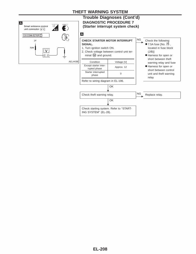
AEL443B
DIAGNOSTIC PROCEDURE 7(Starter interrupt system check)
CHECK STARTER MOTOR INTERRUPTSIGNAL.1. Turn ignition switch ON.2. Check voltage between control unit ter-
minal s32 and ground.
Refer to wiring diagram in EL-196.
OK
c
NG Check the following:● 7.5A fuse [No. ,
located in fuse block(J/B)]
● Harness for open orshort between theftwarning relay and fuse
● Harness for open orshort between controlunit and theft warningrelay
Check theft warning relay.
OKc
NG Replace relay.
Check starting system. Refer to ‘‘START-ING SYSTEM’’ (EL-28).
Condition Voltage [V]
Except starter inter-rupted phase
Approx. 12
Starter interruptedphase
0
THEFT WARNING SYSTEMTrouble Diagnoses (Cont’d)
.
.
EL-208
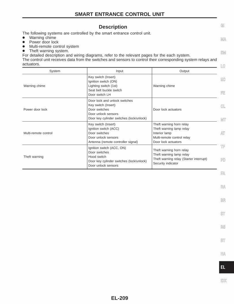
DescriptionThe following systems are controlled by the smart entrance control unit.● Warning chime● Power door lock● Multi-remote control system● Theft warning system.For detailed description and wiring diagrams, refer to the relevant pages for the each system.The control unit receives data from the switches and sensors to control their corresponding system relays andactuators.
System Input Output
Warning chime
Key switch (Insert)Ignition switch (ON)Lighting switch (1st)Seat belt buckle switchDoor switch LH
Warning chime
Power door lock
Door lock and unlock switchesKey switch (Insert)Door switchesDoor unlock sensorsDoor key cylinder switches (lock/unlock)
Door lock actuators
Multi-remote control
Key switch (Insert)Ignition switch (ACC)Door switchesDoor unlock sensorsAntenna (remote controller signal)
Theft warning horn relayTheft warning lamp relayInterior lampMulti-remote control relayDoor lock actuators
Theft warning
Ignition switch (ACC, ON)Door switchesHood switchDoor key cylinder switches (lock/unlock)Door unlock sensors
Theft warning horn relayTheft warning lamp relayTheft warning relay (Starter interrupt)Security indicator
GI
MA
EM
LC
EC
FE
CL
MT
AT
TF
PD
FA
RA
BR
ST
RS
BT
HA
EL
IDX
SMART ENTRANCE CONTROL UNIT
EL-209
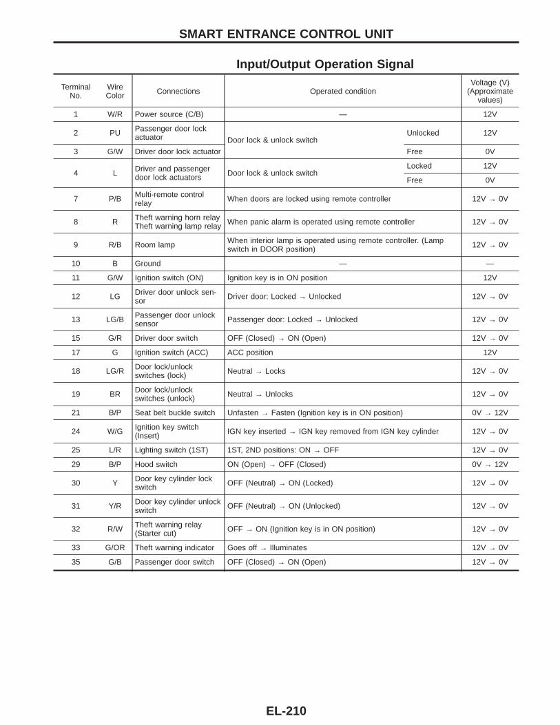
Input/Output Operation Signal
TerminalNo.
WireColor Connections Operated condition
Voltage (V)(Approximate
values)
1 W/R Power source (C/B) — 12V
2 PU Passenger door lockactuator Door lock & unlock switch
Unlocked 12V
3 G/W Driver door lock actuator Free 0V
4 L Driver and passengerdoor lock actuators Door lock & unlock switch
Locked 12V
Free 0V
7 P/B Multi-remote controlrelay When doors are locked using remote controller 12V → 0V
8 R Theft warning horn relayTheft warning lamp relay When panic alarm is operated using remote controller 12V → 0V
9 R/B Room lamp When interior lamp is operated using remote controller. (Lampswitch in DOOR position) 12V → 0V
10 B Ground — —
11 G/W Ignition switch (ON) Ignition key is in ON position 12V
12 LG Driver door unlock sen-sor Driver door: Locked → Unlocked 12V → 0V
13 LG/B Passenger door unlocksensor Passenger door: Locked → Unlocked 12V → 0V
15 G/R Driver door switch OFF (Closed) → ON (Open) 12V → 0V
17 G Ignition switch (ACC) ACC position 12V
18 LG/R Door lock/unlockswitches (lock) Neutral → Locks 12V → 0V
19 BR Door lock/unlockswitches (unlock) Neutral → Unlocks 12V → 0V
21 B/P Seat belt buckle switch Unfasten → Fasten (Ignition key is in ON position) 0V → 12V
24 W/G Ignition key switch(Insert) IGN key inserted → IGN key removed from IGN key cylinder 12V → 0V
25 L/R Lighting switch (1ST) 1ST, 2ND positions: ON → OFF 12V → 0V
29 B/P Hood switch ON (Open) → OFF (Closed) 0V → 12V
30 Y Door key cylinder lockswitch OFF (Neutral) → ON (Locked) 12V → 0V
31 Y/R Door key cylinder unlockswitch OFF (Neutral) → ON (Unlocked) 12V → 0V
32 R/W Theft warning relay(Starter cut) OFF → ON (Ignition key is in ON position) 12V → 0V
33 G/OR Theft warning indicator Goes off → Illuminates 12V → 0V
35 G/B Passenger door switch OFF (Closed) → ON (Open) 12V → 0V
SMART ENTRANCE CONTROL UNIT
EL-210
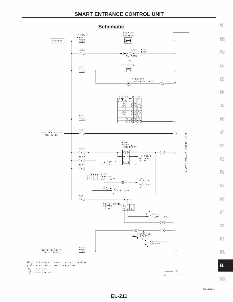
Schematic
AEL292C
GI
MA
EM
LC
EC
FE
CL
MT
AT
TF
PD
FA
RA
BR
ST
RS
BT
HA
EL
IDX
SMART ENTRANCE CONTROL UNIT
EL-211
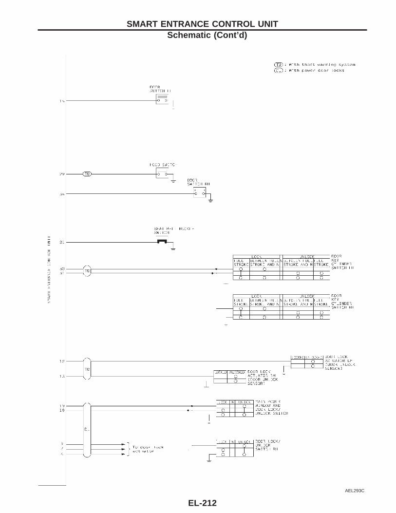
AEL293C
SMART ENTRANCE CONTROL UNITSchematic (Cont’d)
EL-212
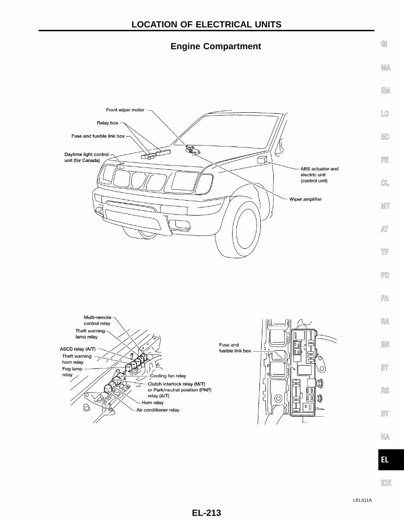
Engine Compartment
LEL511A
GI
MA
EM
LC
EC
FE
CL
MT
AT
TF
PD
FA
RA
BR
ST
RS
BT
HA
EL
IDX
LOCATION OF ELECTRICAL UNITS
EL-213
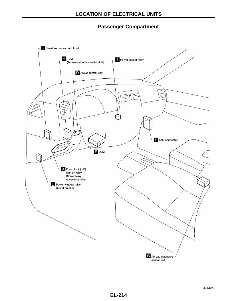
Passenger Compartment
LEL512A
LOCATION OF ELECTRICAL UNITS
EL-214
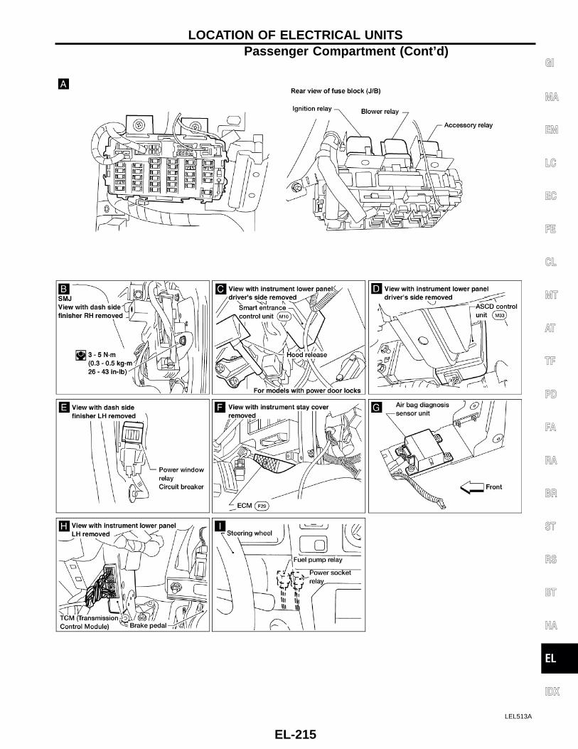
LEL513A
GI
MA
EM
LC
EC
FE
CL
MT
AT
TF
PD
FA
RA
BR
ST
RS
BT
HA
EL
IDX
LOCATION OF ELECTRICAL UNITSPassenger Compartment (Cont’d)
EL-215
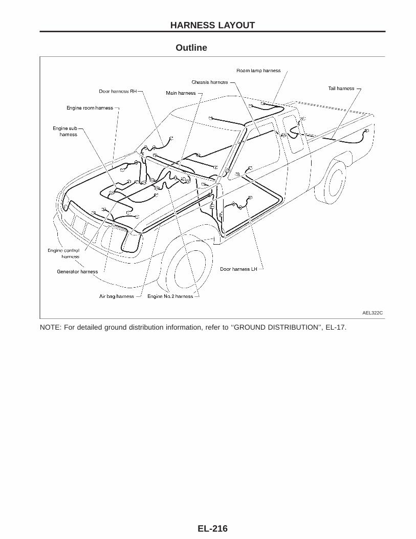
Outline
AEL322C
NOTE: For detailed ground distribution information, refer to ‘‘GROUND DISTRIBUTION’’, EL-17.
HARNESS LAYOUT
EL-216
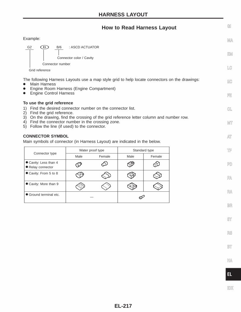
How to Read Harness Layout
Example:
G2 sE1 B/6 : ASCD ACTUATOR
Connector color / Cavity
Connector number
Grid reference
The following Harness Layouts use a map style grid to help locate connectors on the drawings:● Main Harness● Engine Room Harness (Engine Compartment)● Engine Control Harness
To use the grid reference1) Find the desired connector number on the connector list.2) Find the grid reference.3) On the drawing, find the crossing of the grid reference letter column and number row.4) Find the connector number in the crossing zone.5) Follow the line (if used) to the connector.
CONNECTOR SYMBOLMain symbols of connector (in Harness Layout) are indicated in the below.
Connector typeWater proof type Standard type
Male Female Male Female
● Cavity: Less than 4● Relay connector
● Cavity: From 5 to 8
● Cavity: More than 9
● Ground terminal etc.—
GI
MA
EM
LC
EC
FE
CL
MT
AT
TF
PD
FA
RA
BR
ST
RS
BT
HA
EL
IDX
HARNESS LAYOUT
EL-217
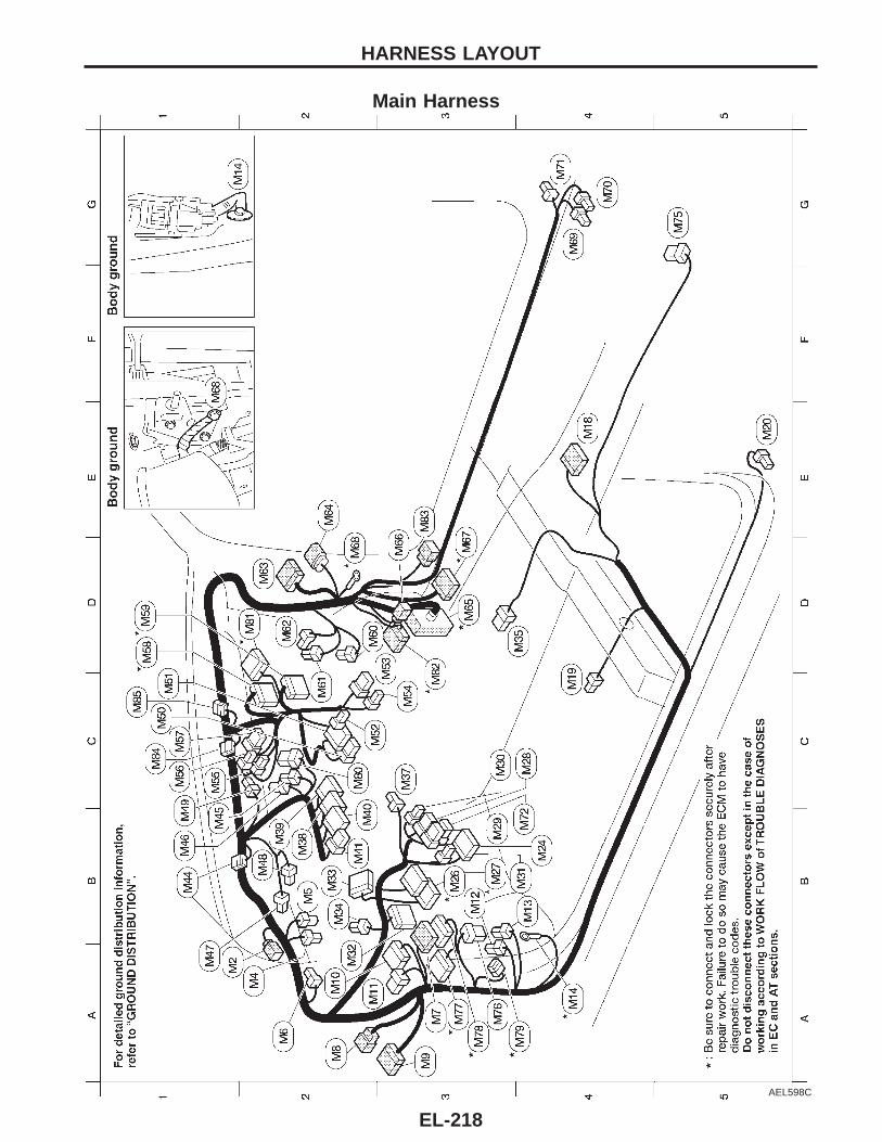
Main Harness
AEL598C
HARNESS LAYOUT
EL-218
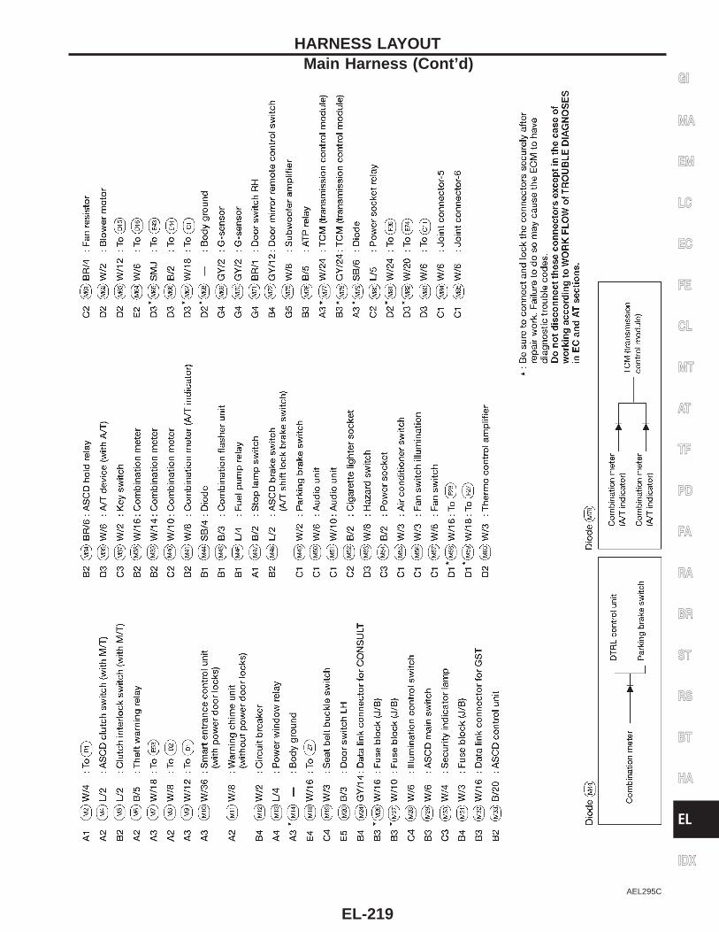
AEL295C
GI
MA
EM
LC
EC
FE
CL
MT
AT
TF
PD
FA
RA
BR
ST
RS
BT
HA
EL
IDX
HARNESS LAYOUTMain Harness (Cont’d)
EL-219
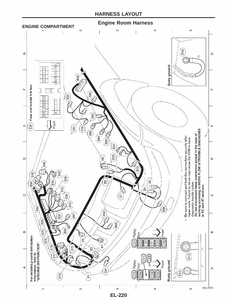
Engine Room HarnessENGINE COMPARTMENT
AEL297C
HARNESS LAYOUT
EL-220
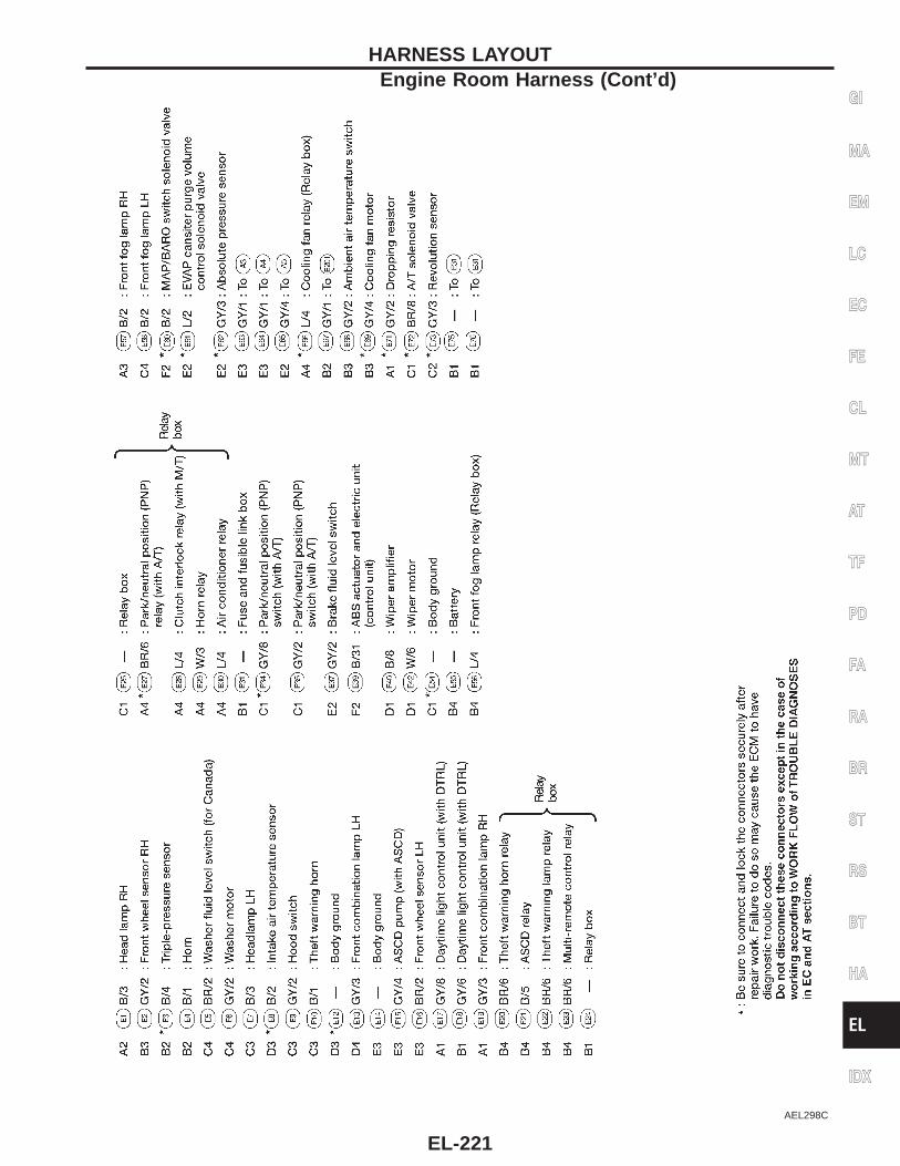
AEL298C
GI
MA
EM
LC
EC
FE
CL
MT
AT
TF
PD
FA
RA
BR
ST
RS
BT
HA
EL
IDX
HARNESS LAYOUTEngine Room Harness (Cont’d)
EL-221
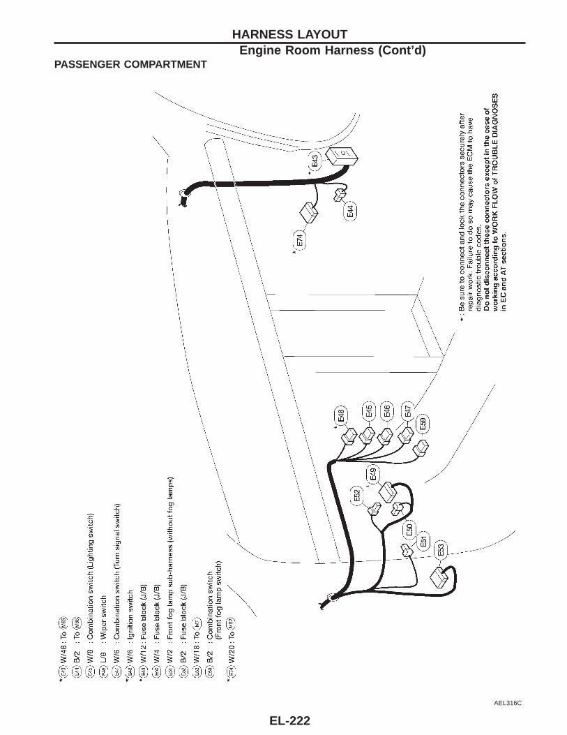
PASSENGER COMPARTMENT
AEL316C
HARNESS LAYOUTEngine Room Harness (Cont’d)
EL-222
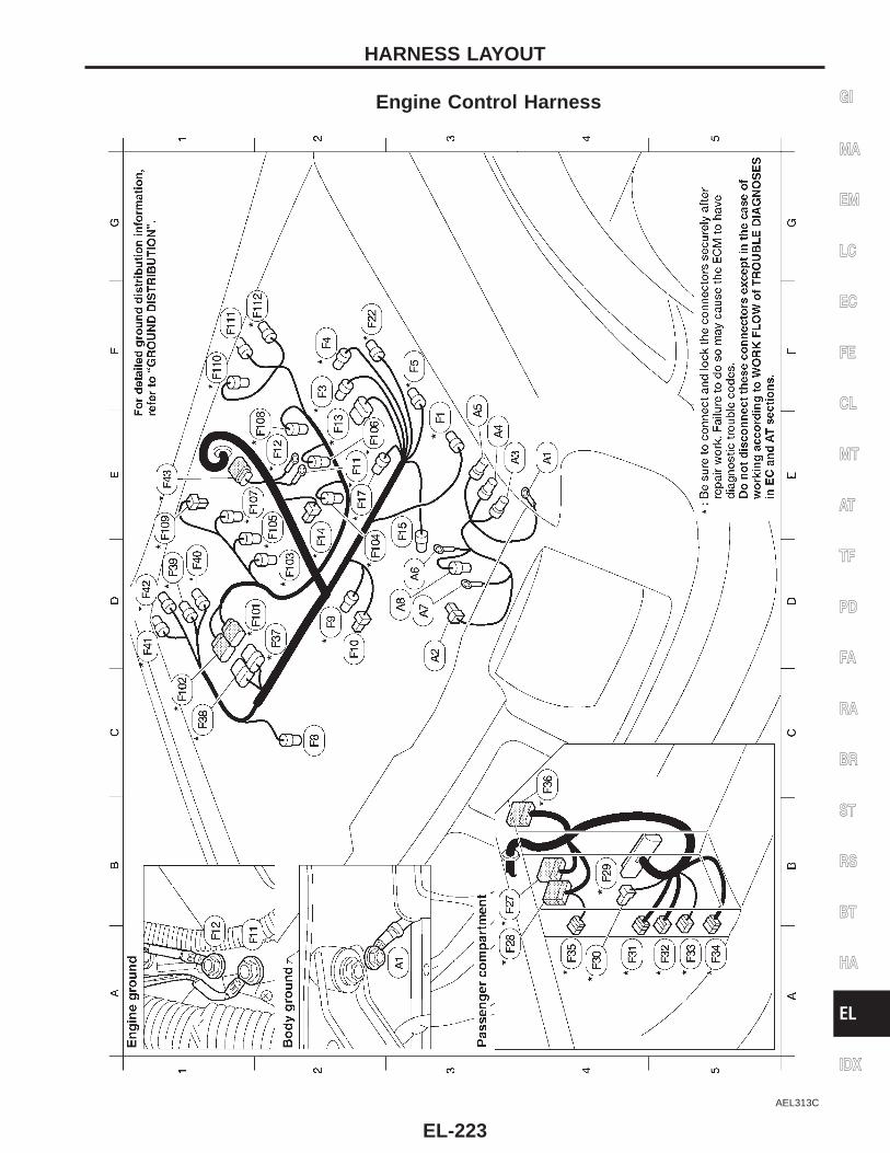
Engine Control Harness
AEL313C
GI
MA
EM
LC
EC
FE
CL
MT
AT
TF
PD
FA
RA
BR
ST
RS
BT
HA
EL
IDX
HARNESS LAYOUT
EL-223
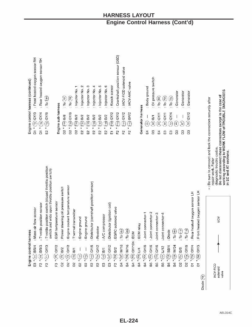
AEL314C
HARNESS LAYOUTEngine Control Harness (Cont’d)
EL-224
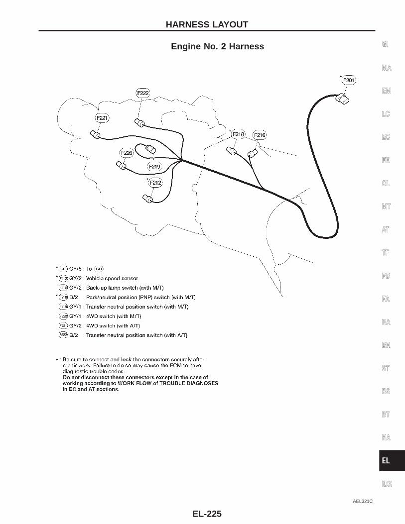
Engine No. 2 Harness
AEL321C
GI
MA
EM
LC
EC
FE
CL
MT
AT
TF
PD
FA
RA
BR
ST
RS
BT
HA
EL
IDX
HARNESS LAYOUT
EL-225
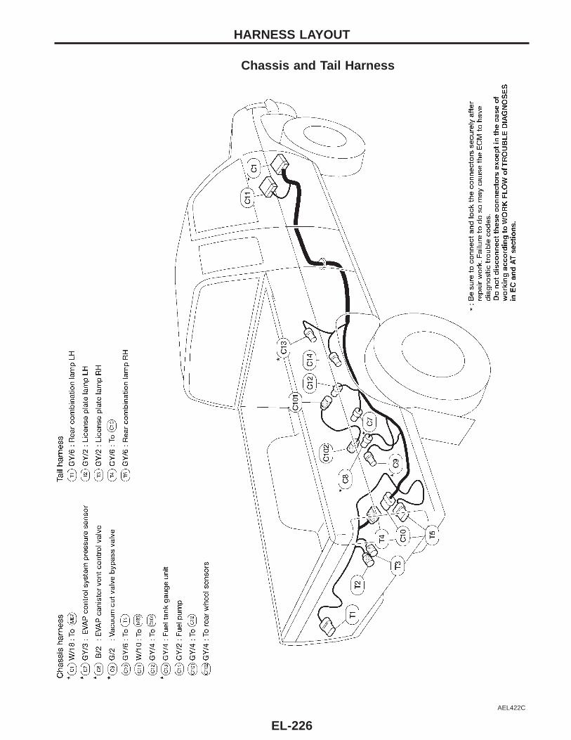
Chassis and Tail Harness
AEL422C
HARNESS LAYOUT
EL-226
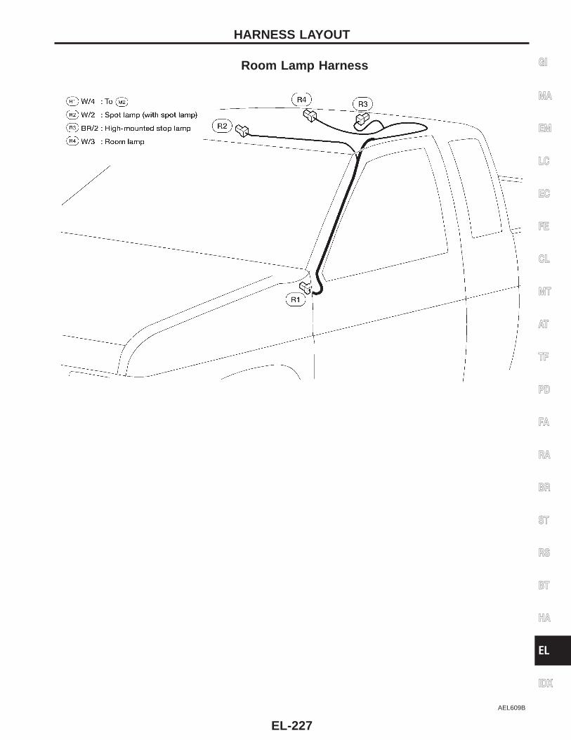
Room Lamp Harness
AEL609B
GI
MA
EM
LC
EC
FE
CL
MT
AT
TF
PD
FA
RA
BR
ST
RS
BT
HA
EL
IDX
HARNESS LAYOUT
EL-227
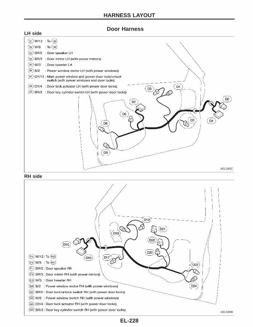
Door HarnessLH side
AEL340C
RH side
AEL589B
HARNESS LAYOUT
EL-228
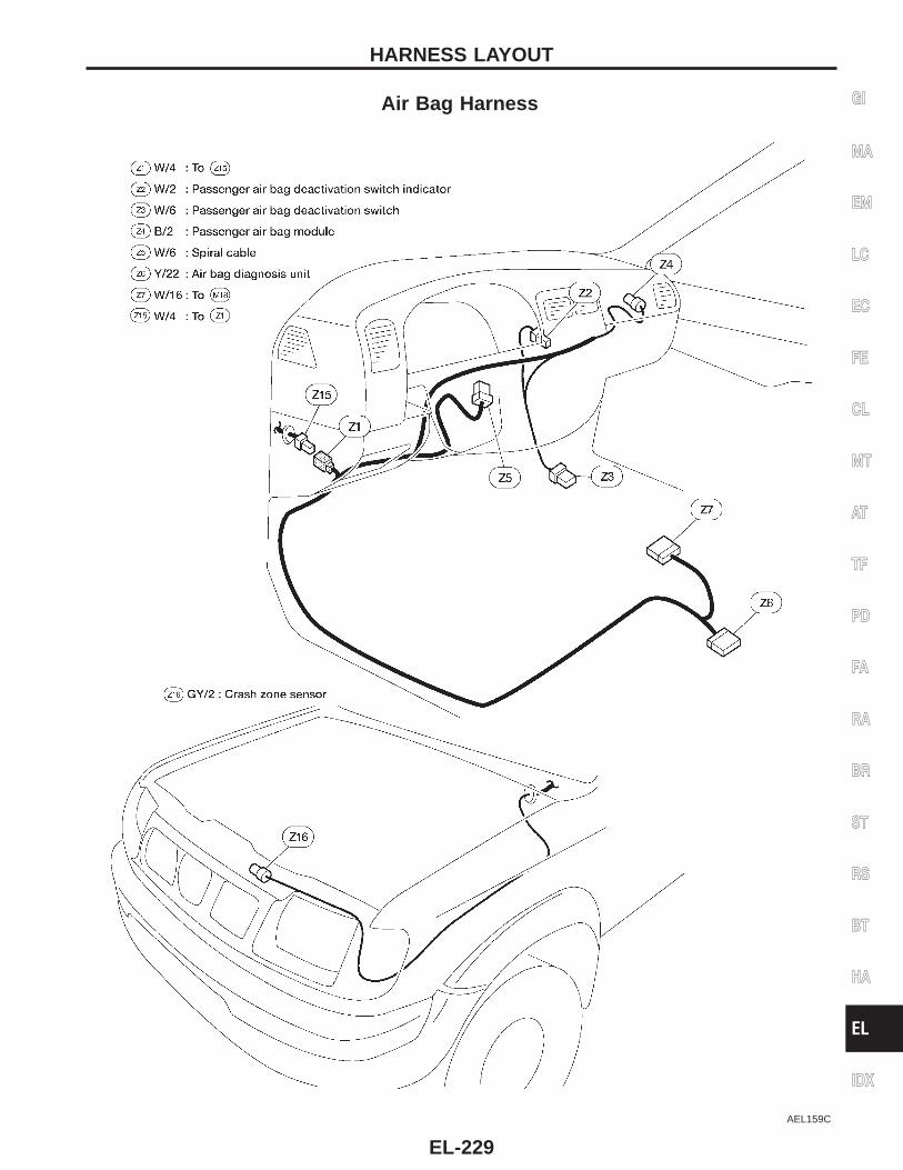
Air Bag Harness
AEL159C
GI
MA
EM
LC
EC
FE
CL
MT
AT
TF
PD
FA
RA
BR
ST
RS
BT
HA
EL
IDX
HARNESS LAYOUT
EL-229
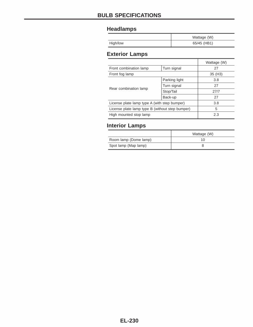
HeadlampsWattage (W)
High/low 65/45 (HB1)
Exterior LampsWattage (W)
Front combination lamp Turn signal 27
Front fog lamp 35 (H3)
Rear combination lamp
Parking light 3.8
Turn signal 27
Stop/Tail 27/7
Back-up 27
License plate lamp type A (with step bumper) 3.8
License plate lamp type B (without step bumper) 5
High mounted stop lamp 2.3
Interior LampsWattage (W)
Room lamp (Dome lamp) 10
Spot lamp (Map lamp) 8
BULB SPECIFICATIONS
EL-230
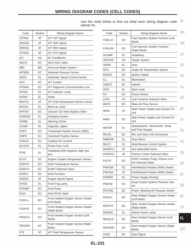
Use the chart below to find out what each wiring diagram codestands for.
Code Section Wiring Diagram Name
1STSIG AT A/T 1ST Signal
2NDSIG AT A/T 2ND Signal
3RDSIG AT A/T 3RD Signal
4THSIG AT A/T 4TH Signal
A/C HA Air Conditioner
AAC/V EC IACV-AAC Valve
ABS BR Anti-Lock Brake System
AP/SEN EC Absolute Pressure Sensor
ASCD EL Automatic Speed Control Device
AT/C EC A/T Control
ATDIAG EC A/T Diagnosis Communication Line
AT/IND EL A/T Indicator Lamp
AUDIO EL Audio
BA/FTS AT A/T Fluid Temperature Sensor Circuit
BACK/L EL Back-up Lamp
BYPS/V EC Vacuum Cut Valve Bypass Valve
CHARGE EL Charging System
CHIME EL Warning Chime
CIGAR EL Cigarette Lighter
CKPS EC Crankshaft Position Sensor (OBD)
CMPS EC Camshaft Position Sensor
COOL/F EC Cooling Fan Control
D/LOCK EL Power Door Lock
DTRL ELHeadlamp-With Daytime Light Sys-tem
ECTS EC Engine Coolant Temperature Sensor
EGR/TS EC EGR Temperature Sensor
EGRC/V EC EGRC-Solenoid Valve
EGRC1 EC EGR Function
ENGSS AT Engine Speed Signal
F/FOG EL Front Fog Lamp
F/PUMP EC Fuel Pump
FICD EC IACV-FICD Valve
FO2H-L ECFront Heated Oxygen Sensor Heater(Left Bank)
FO2H-R ECFront Heated Oxygen Sensor Heater(Right Bank)
FRO2LH ECFront Heated Oxygen Sensor (LeftBank)
FRO2RH ECFront Heated Oxygen Sensor (RightBank)
FTS AT A/T Fluid Temperature Sensor
Code Section Wiring Diagram Name
FUELLH ECFuel Injection System Function (LeftBank)
FUELRH ECFuel Injection System Function(Right Bank)
H/LAMP EL Headlamp
HEATER HA Heater System
HORN EL Horn
IATS EC Intake Air Temperature Sensor
IGN/SG EC Ignition Signal
ILL EL Illumination
INJECT EC Injector
INT/L EL Spot Lamp
KS EC Knock Sensor
LPSV AT Line Pressure Solenoid Valve
MAFS EC Mass Air Flow Sensor
MAIN ATMain Power Supply and Ground Cir-cuit
MAIN ECMain Power Supply and Ground Cir-cuit
METER ELSpeedometer, Tachometer, Temp.and Fuel Gauges
MIL/DL EC MIL and Data Link Connectors
MIRROR EL Door Mirror
MULTI EL Multi-Remote Control System
NONDTC AT Non-detectable Items
OVRCSV AT Overrun Clutch Solenoid Valve
PGC/V ECEVAP Canister Purge Volume Con-trol Solenoid Valve
PNP/SW EC Park/Neutral Position (PNP) Switch
PNP/SW AT Park/Neutral Position (PNP) Switch
POWER EL Power Supply Routing
PRE/SE ECEvap Control System Pressure Sen-sor
PST/SW EC Power Steering Oil Pressure Switch
RO2H-L ECRear Heated Oxygen Sensor Heater(Left Bank)
RO2H-R ECRear Heated Oxygen Sensor Heater(Right Bank)
ROOM/L EL Interior Room Lamp
RRO2LH ECRear Heated Oxygen Sensor (LeftBank)
RRO2RH ECRear Heated Oxygen Sensor (RightBank)
S/SIG EC Start Signal
GI
MA
EM
LC
EC
FE
CL
MT
AT
TF
PD
FA
RA
BR
ST
RS
BT
HA
EL
IDX
WIRING DIAGRAM CODES (CELL CODES)
EL-231
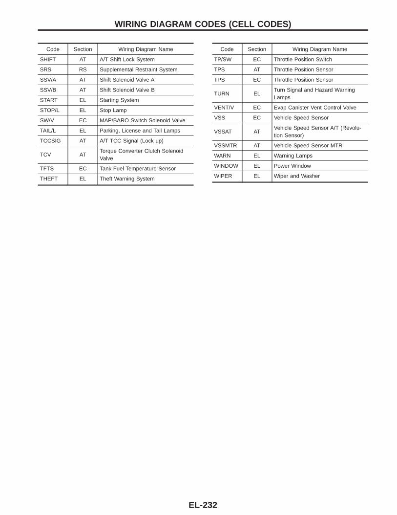
Code Section Wiring Diagram Name
SHIFT AT A/T Shift Lock System
SRS RS Supplemental Restraint System
SSV/A AT Shift Solenoid Valve A
SSV/B AT Shift Solenoid Valve B
START EL Starting System
STOP/L EL Stop Lamp
SW/V EC MAP/BARO Switch Solenoid Valve
TAIL/L EL Parking, License and Tail Lamps
TCCSIG AT A/T TCC Signal (Lock up)
TCV ATTorque Converter Clutch SolenoidValve
TFTS EC Tank Fuel Temperature Sensor
THEFT EL Theft Warning System
Code Section Wiring Diagram Name
TP/SW EC Throttle Position Switch
TPS AT Throttle Position Sensor
TPS EC Throttle Position Sensor
TURN ELTurn Signal and Hazard WarningLamps
VENT/V EC Evap Canister Vent Control Valve
VSS EC Vehicle Speed Sensor
VSSAT ATVehicle Speed Sensor A/T (Revolu-tion Sensor)
VSSMTR AT Vehicle Speed Sensor MTR
WARN EL Warning Lamps
WINDOW EL Power Window
WIPER EL Wiper and Washer
WIRING DIAGRAM CODES (CELL CODES)
EL-232