Embed Size (px)
Citation preview
7/28/2019 Electro Wetting
http://slidepdf.com/reader/full/electro-wetting 1/11
New Methods to
Transport Fluids inMicro-Sized DevicesS B Jkb Ksk
Microfuidics encompasses the science
and technology of systems that process or
manipulate extremely small volumes of
uids, generally ranging from nanoliters to
attoliters (10–9 to 10–18 liters). Applications span from
physical-science-based applications such as inkjet print-
ers and microfuel cells to biotechnology applications
such as DNA analysis and drug discovery. The appeal of
microuidics, particularly in biotechnology, is the ability
to separate and detect cells, molecules, and other entities
and to perform analyses more quickly and with increased
sensitivity, automation, and parallelization. Moreover,
the reduction in reagent and sample volumes means less
cost per analysis [1]. Such miniaturization also opens up
the possibility of developing portable devices for medical
diagnostic tools or environmental monitors.
However, the miniaturization of uid systems poses
signicant challenges. For example, the fundamental task
of integrating uid into a micro-sized device can be dif-
cult because uid-handling tools required to go from the
macro-world to the micro-world are not yet well estab-
lished. In addition, the ability to precisely control and
transport uid in micro-sized structures presents its own
unique set of challenges.
At the root of these challenges is fundamental uid
physics. For devices in which feature dimensions are on
the scale of micrometers and uid volumes on the order
of nanoliters, surface tension, viscosity, and electrical
charges become dominant forces over inertial forces. As
a consequence, performing the basic uidic operations
that are essential to the functionality of the system—
such as uid transport, mixing, and ltering—requires
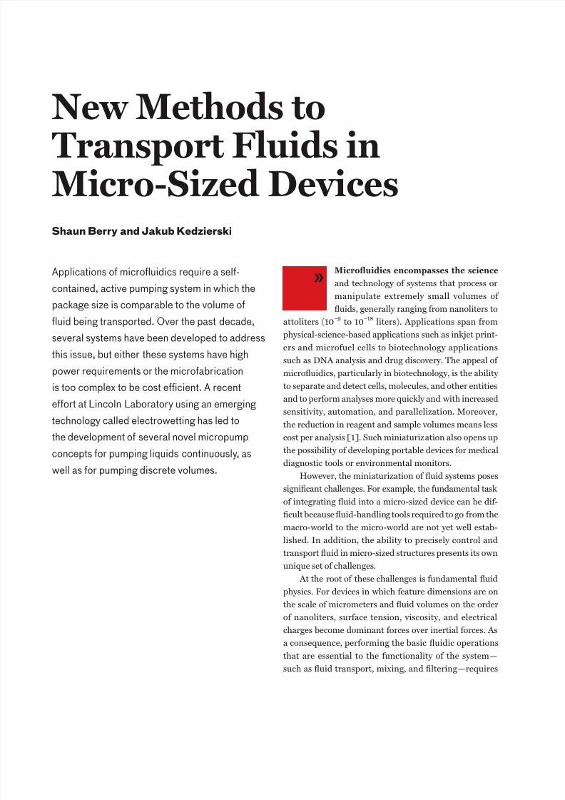
Applications o microuidics require a sel-
contained, active pumping system in which the
package size is comparable to the volume o
uid being transported. Over the past decade,
several systems have been developed to address
this issue, but either these systems have high
power requirements or the microabrication
is too complex to be cost efcient. A recent
eort at Lincoln Laboratory using an emerging
technology called electrowetting has led tothe development o several novel micropump
concepts or pumping liquids continuously, as
well as or pumping discrete volumes.
»
7/28/2019 Electro Wetting
http://slidepdf.com/reader/full/electro-wetting 2/11
Shaun Berry and JaKuB K edzierSKi
unorthodox and innova-
tive approaches.
In a large number
of microfluidic systems,
fluids are transported by pressure gradients gener-
ated from pumps exter-
nal to the device. In these
types of systems, the over-
all size is dominated by the
size of the external pump-
ing components, which
are typically large relative
to the microuidic device
itself. This approach may
be suitable for a broad range of applications; a key factor
for a truly miniaturized system, however, is to have a self-
contained pumping and uid transport system [2]. Sys-
tems that generate pressure on chip have been based on
a wide range of effects, including electro-osmosis [3, 4],
electrophoresis [5], electromagnetism [6], acoustics
[7], and thermocapillary effects [8]. In addition, self-
contained micropumps have been developed that consist
of moving solid boundaries in microelectromechanical
systems, or MEMS [2, 9, 10].
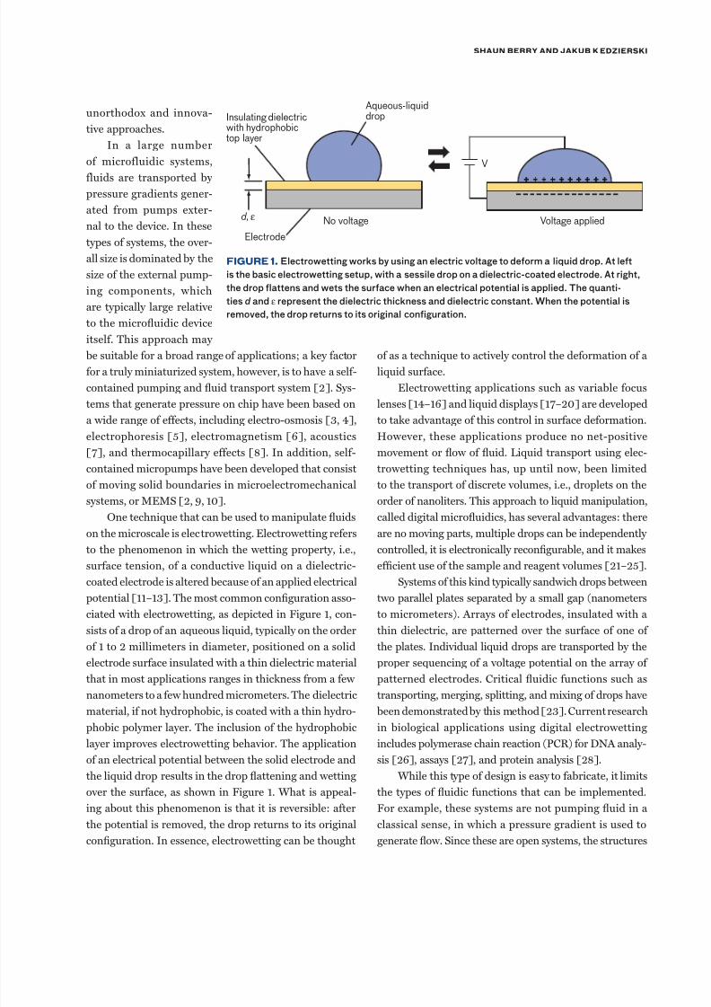
One technique that can be used to manipulate uids
on the microscale is electrowetting. Electrowetting refers
to the phenomenon in which the wetting property, i.e.,
surface tension, of a conductive liquid on a dielectric-
coated electrode is altered because of an applied electrical
potential [11–13]. The most common conguration asso-
ciated with electrowetting, as depicted in Figure 1, con-
sists of a drop of an aqueous liquid, typically on the order
of 1 to 2 millimeters in diameter, positioned on a solid
electrode surface insulated with a thin dielectric material
that in most applications ranges in thickness from a few
nanometers to a few hundred micrometers. The dielectric
material, if not hydrophobic, is coated with a thin hydro-
phobic polymer layer. The inclusion of the hydrophobic
layer improves electrowetting behavior. The application
of an electrical potential between the solid electrode and
the liquid drop results in the drop attening and wetting
over the surface, as shown in Figure 1. What is appeal-
ing about this phenomenon is that it is reversible: after
the potential is removed, the drop returns to its original
conguration. In essence, electrowetting can be thought
of as a technique to actively control the deformation of a
liquid surface.
Electrowetting applications such as variable focus
lenses [14–16] and liquid displays [17–20] are developed
to take advantage of this control in surface deformation.
However, these applications produce no net-positive
movement or ow of uid. Liquid transport using elec-
trowetting techniques has, up until now, been limited
to the transport of discrete volumes, i.e., droplets on the
order of nanoliters. This approach to liquid manipulation,
called digital microuidics, has several advantages: there
are no moving parts, multiple drops can be independently
controlled, it is electronically recongurable, and it makes
efcient use of the sample and reagent volumes [21–25].
Systems of this kind typically sandwich drops between
two parallel plates separated by a small gap (nanometers
to micrometers). Arrays of electrodes, insulated with a
thin dielectric, are patterned over the surface of one of
the plates. Individual liquid drops are transported by the
proper sequencing of a voltage potential on the array of
patterned electrodes. Critical uidic functions such as
transporting, merging, splitting, and mixing of drops have
been demonstrated by this method [23]. Current research
in biological applications using digital electrowetting
includes polymerase chain reaction (PCR) for DNA analy-
sis [26], assays [27], and protein analysis [28].
While this type of design is easy to fabricate, it limits
the types of uidic functions that can be implemented.
For example, these systems are not pumping uid in a
classical sense, in which a pressure gradient is used to
generate ow. Since these are open systems, the structures
FiGure 1. Electrowetting works by using an electric voltage to deorm a liquid drop. At let
is the basic electrowetting setup, with a sessile drop on a dielectric-coated electrode. At right,
the drop lattens and wets the surace when an electrical potential is applied. The quanti-
ties d and ε represent the dielectric thickness and dielectric constant. When the potential is
removed, the drop returns to its original coniguration.
Insulating dielectricwith hydrophobictop layer
Electrode
No voltage Voltage applied
V
d, ε
Aqueous-liquiddrop
7/28/2019 Electro Wetting
http://slidepdf.com/reader/full/electro-wetting 3/11
new methodS to tranSport FluidS in micro-Sized deviceS
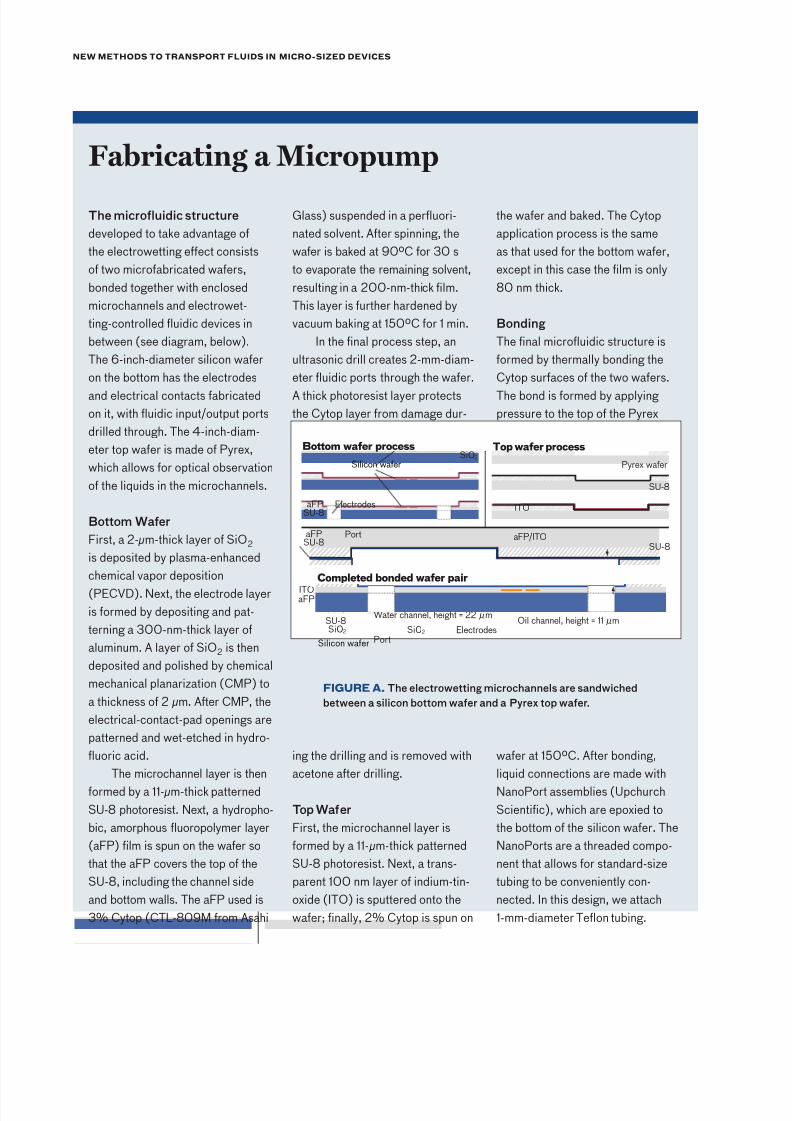
The microfuidic structure
developed to take advantage o
the electrowetting eect consists
o two microabricated waers,
bonded together with enclosed
microchannels and electrowet-
ting-controlled uidic devices in
between (see diagram, below).
The 6-inch-diameter silicon waer
on the bottom has the electrodes
and electrical contacts abricatedon it, with uidic input/output ports
drilled through. The 4-inch-diam-
eter top waer is made o Pyrex,
which allows or optical observation
o the liquids in the microchannels.
Bottom Waer
First, a 2- µm-thick layer o SiO2
is deposited by plasma-enhanced
chemical vapor deposition
(PECVD). Next, the electrode layer
is ormed by depositing and pat-
terning a 300-nm-thick layer o
aluminum. A layer o SiO2 is then
deposited and polished by chemical
mechanical planarization (CMP) to
a thickness o 2 µm. Ater CMP, the
electrical-contact-pad openings are
patterned and wet-etched in hydro-
uoric acid.
The microchannel layer is then
ormed by a 11- µm-thick patterned
SU-8 photoresist. Next, a hydropho-
bic, amorphous uoropolymer layer
(aFP) flm is spun on the waer so
that the aFP covers the top o the
SU-8, including the channel side
and bottom walls. The aFP used is
3% Cytop (CTL-809M rom Asahi
Glass) suspended in a peruori-
nated solvent. Ater spinning, the
waer is baked at 90ºC or 30 s
to evaporate the remaining solvent,
resulting in a 200-nm-thick flm.
This layer is urther hardened by
vacuum baking at 150ºC or 1 min.
In the fnal process step, an
ultrasonic drill creates 2-mm-diam-
eter uidic ports through the waer.
A thick photoresist layer protectsthe Cytop layer rom damage dur-
ing the drilling and is removed with
acetone ater drilling.
Top Waer
First, the microchannel layer is
ormed by a 11- µm-thick patterned
SU-8 photoresist. Next, a trans-
parent 100 nm layer o indium-tin-
oxide (ITO) is sputtered onto the
waer; fnally, 2% Cytop is spun on
the waer and baked. The Cytop
application process is the same
as that used or the bottom waer,
except in this case the flm is only
80 nm thick.
Bonding
The fnal microuidic structure is
ormed by thermally bonding the
Cytop suraces o the two waers.
The bond is ormed by applying pressure to the top o the Pyrex
waer at 150ºC. Ater bonding,
liquid connections are made with
NanoPort assemblies (Upchurch
Scientifc), which are epoxied to
the bottom o the silicon waer. The
NanoPorts are a threaded compo-
nent that allows or standard-size
tubing to be conveniently con-
nected. In this design, we attach
1-mm-diameter Teon tubing.
Fabricating a Micropump
FiGure a. The electrowetting microchannels are sandwiched
between a silicon bottom waer and a Pyrex top waer.
SU-8
Pyrex wafer
Port
Water channel, height = 22 µ mOil channel, height = 11 µ m
Silicon wafer
SU-8Si02 Si02
Completed bonded wafer pair
ITOaFP
Electrodes
Top wafer process
ITO
aFP/ITOSU-8
SU-8
Pyrex wafer
SU-8Port
Bottom wafer process
Silicon wafer
Electrodes
aFP
SU-8aFP
Si02
7/28/2019 Electro Wetting
http://slidepdf.com/reader/full/electro-wetting 4/11
Shaun Berry and JaKuB K edzierSKi
have no ow channels; thus no positive pressure can be
achieved. The motivation for our work is to take advan-
tage of electrowetting’s key attributes (low power, lack of
moving solid parts, and small size) and apply them for
transporting liquids in closed-microchannel structures.Deforming a liquid interface in a closed microchannel cre-
ates the pressure gradients required to drive uid motion.
The ability to do pressure work in a closed microchannel
will enable the development of integrated micropumps, as
well as other devices that form valves, pistons, and drop
generators—all the essential elements required in micro-
uidic systems.
dsg
The idea behind the devices fabricated was to use the
mechanical work resulting from the displacement of the
liquid interface to do pressure work. All the uidic devices
were designed to operate by using two immiscible liquids:
water as the conductive liquid and low-viscosity oil (in
particular, dodecane oil) as an insulating liquid. We have
already studied the electrowetting properties of this two-
liquid system [29–31]. The use of an oil phase prevents
evaporation and limits hysteresis effects that often arise
in water-gas microchannel systems [32].
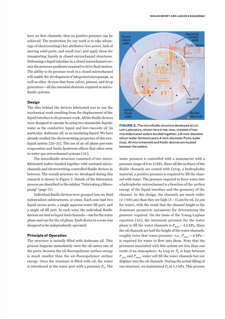
The microuidic structure consisted of two micro-
fabricated wafers bonded together with enclosed micro-
channels and electrowetting-controlled uidic devices in
between. The overall structure we developed during this
research is shown in Figure 2. Details of the fabrication
process are described in the sidebar “Fabricating a Micro-
pump” (page 72).
Individual uidic devices were grouped into six uid
independent substructures, or zones. Each zone had two
liquid access ports, a single aqueous-water ll port, and
a single oil ll port. In each zone, the individual uidic
devices are tied to liquid feed channels—one for the water
phase and one for the oil phase. Each device in a zone was
designed to be independently operated.
p f o
The structure is initially lled with dodecane oil. This
process happens immediately once the oil enters one of
the ports, because the oil-uoropolymer surface energy
is much smaller than the air-fluoropolymer surface
energy. Once the structure is lled with oil, the water
is introduced at the water port with a pressure P b. The
water pressure is controlled with a manometer with a
pressure range of 0 to 15 kPa. Since all the surfaces of the
uidic channels are coated with Cytop, a hydrophobic
material, a positive pressure is required to ll the chan-
nel with water. The pressure required to force water into
a hydrophobic microchannel is a function of the surface
energy of the liquid interface and the geometry of the
channel. In this design, the channels are much wider
(w ≥100 µm) than they are high (h = 11 µm for oil, 22 µm
for water), with the result that the channel height is the
dominant geometric parameter for determining the
pressure required. On the basis of the Young-Laplace
equation [33], the minimum pressure for the water
phase to ll the water channels is P min = 4.5 kPa. Since
the oil channels are half the height of the water channels,
roughly twice that water pressure—i.e., P max = 9 kPa—
is required for water to ow into them. Note that the
pressures associated with this system are less than one
tenth of an atmosphere. As long as P b is kept between
P min and P max , water will ll the water channels but not
displace into the oil channels. During the actual lling of
our structure, we maintained P b at 5.5 kPa. This process
FiGure 2. The microluidic structure developed at Lin-
coln Laboratory, shown here in top view, consists o two
microabricated waers bonded together: a 6-inch-diameter
silicon waer (bottom) and a 4-inch-diameter Pyrex waer
(top). All microchannels and luidic devices are located
between the waers.
4-inchPyrexwafer
Buriedelectrode
Liquid-fillport
Fluidic device
Electricalcontact
pads6-inchsiliconwafer
7/28/2019 Electro Wetting
http://slidepdf.com/reader/full/electro-wetting 5/11
new methodS to tranSport FluidS in micro-Sized deviceS
worked well to give a slow and controllable water ll.
At this pressure, the water displaces oil from the water
channels but not from the oil channels. Figure 3 shows
a representative channel cross section of a lled single-
electrode device prior to voltage actuation.
Single-Electrode Actuation. With P b maintained
between P min and P max , the water/oil interface stays
located at the step in channel height, as shown in Figure
3. To actively control the position of the interface, elec-
trowetting is used to advance the water phase into the
lower-height oil channel. Key to predicting the electrowet-
ting behavior in a microchannel is the capacitance. The
capacitances per unit area from the top of the indium-tin-
oxide (ITO) ground to the bottom electrode are C w
in the
water channel andC o
in the oil channel. Because water is
treated as a conductor, C w
does not depend on the chan-
nel height; oil, however, is not a conductor and so C o
does
depend on channel height. The expressions for C w
and C o
can be found in Reference 34.
When the voltage is applied to the bottom electrode,
electrowetting pressure is included through Lippmann’s
equation [11] in the Young-Laplace equation, where the
pressure difference across the water/oil interface becomes
∆P h
C V
h = −
2
2
2γ w
o o
* *
,
whereγ w
*
is the difference in the water-uoropolymer and
oil-uoropolymer surface energies and is approximately
50 mJ/m2; h o
is the height of the oil channel, C *
= C w –
C o
; and V is the potential applied to the bottom electrode
relative to the ITO ground. The rst term on the right-
hand side is the pressure across an interface, based on
the channel geometry, and is the Young-Laplace equation.The second term on the right-hand side is the change in
pressure due to electrowetting.
If ∆P = P b, there is no interface movement or liq-
uid motion, since the pressure across the water/oil inter-
face is balanced against the applied pressure. Thus no
useful work is done. If ∆P ≠ P b, then a working pres-
sure is dened as P s = P b – ∆P , where P s is the pressure
that causes the interface and liquids to move. If P s = 0,
meaning ∆P = P b, then there is no interface movement,
because the pressure difference across the interface does
no work. When V becomes sufciently large to generate
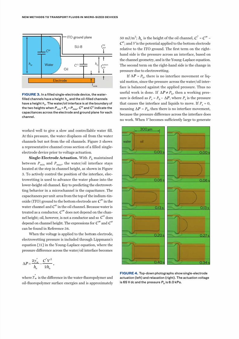
FiGure 3. In a illed single-electrode device, the water-
illed channels have a height hw and the oil-illed channels
have a height ho. The water/oil interace is at the boundary o
the two heights when P min < P b < P max . C w and C o indicate the
capacitances across the electrode and ground plane or each
channel.
FiGure 4. Top-down photographs show single-electrode
actuation (let) and relaxation (right). The actuation voltage
is 65 V dc and the pressureP b is 8.0 kPa.
hW
hO
t aFP
top
CW
Water
OilCO
t aFP
t oxide
SU-8
ITO ground plane
bottom
Electrode
300 m
water oil
0.00 s 0.00 s
0.06 s 0.06 s
0.13 s 0.13 s
0.20 s 0.27 s
0.40 s 0.34 s
µ
7/28/2019 Electro Wetting
http://slidepdf.com/reader/full/electro-wetting 6/11
Shaun Berry and JaKuB K edzierSKi
a positive P s, it causes water to move into the oil chan-
nel. This voltage-induced actuation is shown in Figure 4
(left). As the gure shows, the interface advances only as
far as the length of the electrode. With the water phase
extended over the electrode, removal of the voltage causes∆P to increase, which makes P s negative and thus forces
the water/oil interface back to its original position at the
boundary between the water channel and the oil channel.
This relaxation is shown in Figure 4 (right). Generally, the
working pressure during actuation differs in magnitude
from the working pressure during recession; as a result,
the two processes occur at different speeds.
Directly measuring the actuation time and relaxation
time with a charge coupled device (CCD) camera and con-
sidering the microchannel dimensions allow us to deter-
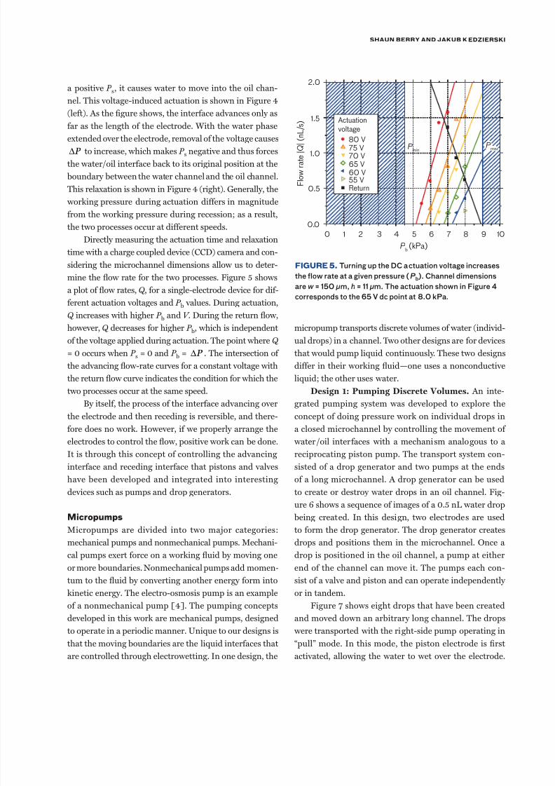
mine the ow rate for the two processes. Figure 5 shows
a plot of ow rates, Q , for a single-electrode device for dif-
ferent actuation voltages and P b values. During actuation,
Q increases with higher P b and V . During the return ow,
however, Q decreases for higher P b, which is independent
of the voltage applied during actuation. The point where Q
= 0 occurs when P s = 0 and P b = ∆P . The intersection of
the advancing ow-rate curves for a constant voltage with
the return ow curve indicates the condition for which the
two processes occur at the same speed.
By itself, the process of the interface advancing over
the electrode and then receding is reversible, and there-
fore does no work. However, if we properly arrange the
electrodes to control the ow, positive work can be done.
It is through this concept of controlling the advancing
interface and receding interface that pistons and valves
have been developed and integrated into interesting
devices such as pumps and drop generators.
ms
Micropumps are divided into two major categories:
mechanical pumps and nonmechanical pumps. Mechani-
cal pumps exert force on a working uid by moving one
or more boundaries. Nonmechanical pumps add momen-
tum to the uid by converting another energy form into
kinetic energy. The electro-osmosis pump is an example
of a nonmechanical pump [4]. The pumping concepts
developed in this work are mechanical pumps, designed
to operate in a periodic manner. Unique to our designs is
that the moving boundaries are the liquid interfaces that
are controlled through electrowetting. In one design, the
micropump transports discrete volumes of water (individ-
ual drops) in a channel. Two other designs are for devices
that would pump liquid continuously. These two designs
differ in their working uid—one uses a nonconductive
liquid; the other uses water.
Design 1: Pumping Discrete Volumes. An inte-
grated pumping system was developed to explore the
concept of doing pressure work on individual drops in
a closed microchannel by controlling the movement of
water/oil interfaces with a mechanism analogous to a
reciprocating piston pump. The transport system con-
sisted of a drop generator and two pumps at the ends
of a long microchannel. A drop generator can be used
to create or destroy water drops in an oil channel. Fig-
ure 6 shows a sequence of images of a 0.5 nL water drop
being created. In this design, two electrodes are used
to form the drop generator. The drop generator creates
drops and positions them in the microchannel. Once a
drop is positioned in the oil channel, a pump at either
end of the channel can move it. The pumps each con-
sist of a valve and piston and can operate independently
or in tandem.
Figure 7 shows eight drops that have been created
and moved down an arbitrary long channel. The drops
were transported with the right-side pump operating in
“pull” mode. In this mode, the piston electrode is rst
activated, allowing the water to wet over the electrode.
2.0
1.5
1.0
F l o w r
a t e | Q | ( n
L / s )
0.5
0.0
0 1 2 3 4 5
P b (kPa)
6 7 8 9 10
P min
P max
Actuationvoltage
80 V75 V70 V65 V60 V55 VReturn
FiGure 5. Turning up the DC actuation voltage increases
the low rate at a given pressure (P b). Channel dimensionsarew = 150 µm, h = 11 µm. The actuation shown in Figure 4
corresponds to the 65 V dc point at 8.0 kPa.
7/28/2019 Electro Wetting
http://slidepdf.com/reader/full/electro-wetting 7/11
new methodS to tranSport FluidS in micro-Sized deviceS
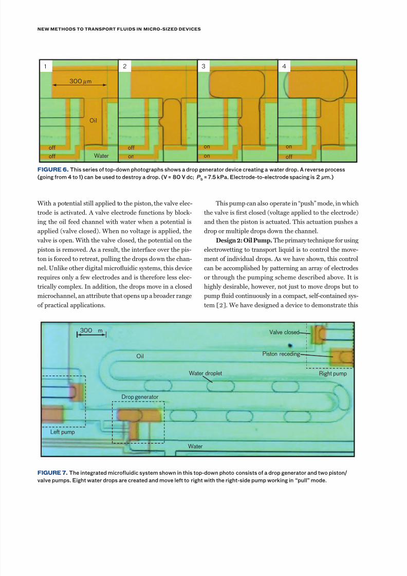
With a potential still applied to the piston, the valve elec-
trode is activated. A valve electrode functions by block-
ing the oil feed channel with water when a potential is
applied (valve closed). When no voltage is applied, the
valve is open. With the valve closed, the potential on the
piston is removed. As a result, the interface over the pis-
ton is forced to retreat, pulling the drops down the chan-
nel. Unlike other digital microuidic systems, this device
requires only a few electrodes and is therefore less elec-
trically complex. In addition, the drops move in a closed
microchannel, an attribute that opens up a broader range
of practical applications.
This pump can also operate in “push” mode, in which
the valve is rst closed (voltage applied to the electrode)
and then the piston is actuated. This actuation pushes a
drop or multiple drops down the channel.
Design 2: Oil Pump. The primary technique for using
electrowetting to transport liquid is to control the move-
ment of individual drops. As we have shown, this control
can be accomplished by patterning an array of electrodes
or through the pumping scheme described above. It is
highly desirable, however, not just to move drops but to
pump uid continuously in a compact, self-contained sys-
tem [2]. We have designed a device to demonstrate this
FiGure 7. The integrated microluidic system shown in this top-down photo consists o a drop generator and two piston/
valve pumps. Eight water drops are created and move let to right with the right-side pump working in “pull” mode.
10
1 2 3 4
on
off
on
on
off
on
off
Oil
off Water
300 µ m
Left pump
Water
Drop generator
Oil
Water droplet
Valve closed
Piston receding
Right pump
300 m
FiGure 6. This series o top-down photographs shows a drop generator device creating a water drop. A reverse process
(going rom 4 to 1) can be used to destroy a drop. (V = 80 V dc; P b = 7.5 kPa. Electrode-to-electrode spacing is 2 µm.)
7/28/2019 Electro Wetting
http://slidepdf.com/reader/full/electro-wetting 8/11
Shaun Berry and JaKuB K edzierSKi
capability. In this design, the oil phase is the working uid
and is pumped continuously through the proper place-
ment of electrodes and sequencing of the electrode timing.
The design consists of two valves and a piston.
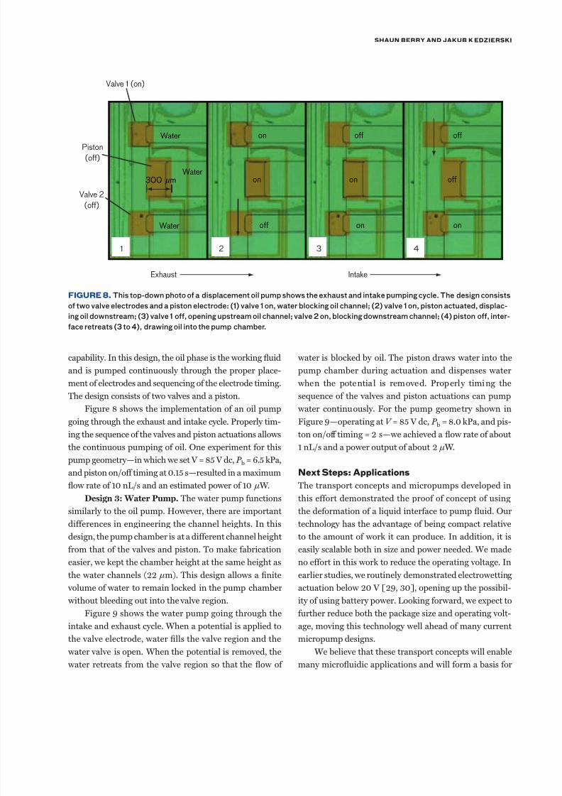
Figure 8 shows the implementation of an oil pump
going through the exhaust and intake cycle. Properly tim-
ing the sequence of the valves and piston actuations allows
the continuous pumping of oil. One experiment for this
pump geometry—in which we set V = 85 V dc, P b = 6.5 kPa,
and piston on/off timing at 0.15 s—resulted in a maximum
ow rate of 10 nL/s and an estimated power of 10 µ W.
Design 3: Water Pump. The water pump functions
similarly to the oil pump. However, there are important
differences in engineering the channel heights. In this
design, the pump chamber is at a different channel height
from that of the valves and piston. To make fabrication
easier, we kept the chamber height at the same height as
the water channels (22 µm). This design allows a nite
volume of water to remain locked in the pump chamber
without bleeding out into the valve region.
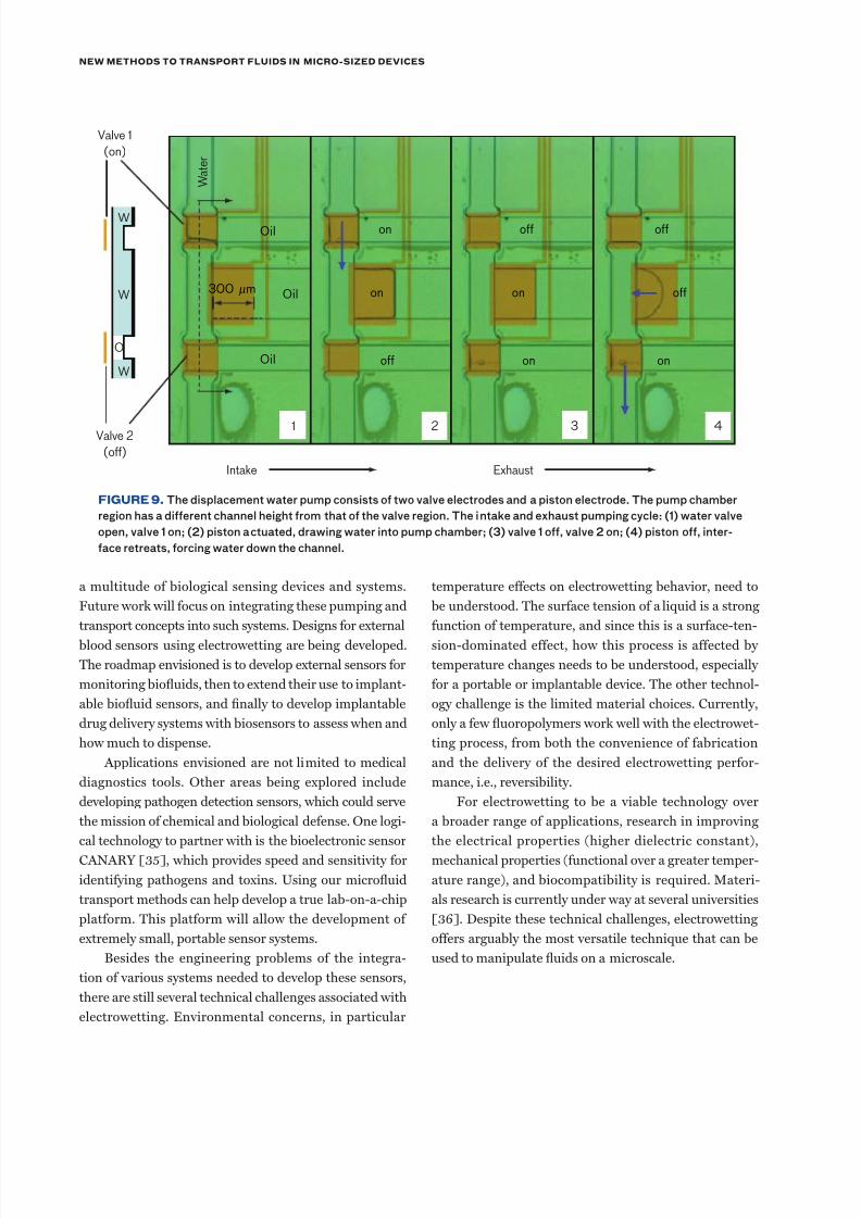
Figure 9 shows the water pump going through the
intake and exhaust cycle. When a potential is applied to
the valve electrode, water lls the valve region and the
water valve is open. When the potential is removed, the
water retreats from the valve region so that the ow of
water is blocked by oil. The piston draws water into the
pump chamber during actuation and dispenses water
when the potential is removed. Properly timing the
sequence of the valves and piston actuations can pump
water continuously. For the pump geometry shown in
Figure 9—operating at V = 85 V dc, P b = 8.0 kPa, and pis-
ton on/off timing = 2 s—we achieved a ow rate of about
1 nL/s and a power output of about 2 µ W.
nx Ss: as
The transport concepts and micropumps developed in
this effort demonstrated the proof of concept of using
the deformation of a liquid interface to pump uid. Our
technology has the advantage of being compact relative
to the amount of work it can produce. In addition, it is
easily scalable both in size and power needed. We made
no effort in this work to reduce the operating voltage. In
earlier studies, we routinely demonstrated electrowetting
actuation below 20 V [29, 30], opening up the possibil-
ity of using battery power. Looking forward, we expect to
further reduce both the package size and operating volt-
age, moving this technology well ahead of many current
micropump designs.
We believe that these transport concepts will enable
many microuidic applications and will form a basis for
FiGure 8. This top-down photo o a displacement oil pump shows the exhaust and intake pumping cycle. The design consists
o two valve electrodes and a piston electrode: (1) valve 1 on, water blocking oil channel; (2) valve 1 on, piston actuated, displac-
ing oil downstream; (3) valve 1 o, opening upstream oil channel; valve 2 on, blocking downstream channel; (4) piston o, inter-
ace retreats (3 to 4), drawing oil into the pump chamber.
Valve 1 (on)
1
Exhaust
Water
Water
Water
on
on
off
on
off
on
off
off
on
2 3 4
Piston
(off)
Valve 2
(off)
Intake
300 mµ
7/28/2019 Electro Wetting
http://slidepdf.com/reader/full/electro-wetting 9/11
new methodS to tranSport FluidS in micro-Sized deviceS
a multitude of biological sensing devices and systems.
Future work will focus on integrating these pumping and
transport concepts into such systems. Designs for external
blood sensors using electrowetting are being developed.
The roadmap envisioned is to develop external sensors for
monitoring biouids, then to extend their use to implant-
able biouid sensors, and nally to develop implantable
drug delivery systems with biosensors to assess when and
how much to dispense.
Applications envisioned are not limited to medical
diagnostics tools. Other areas being explored include
developing pathogen detection sensors, which could serve
the mission of chemical and biological defense. One logi-
cal technology to partner with is the bioelectronic sensor
CANARY [35], which provides speed and sensitivity for
identifying pathogens and toxins. Using our microuid
transport methods can help develop a true lab-on-a-chip
platform. This platform will allow the development of
extremely small, portable sensor systems.
Besides the engineering problems of the integra-
tion of various systems needed to develop these sensors,
there are still several technical challenges associated with
electrowetting. Environmental concerns, in particular
temperature effects on electrowetting behavior, need to
be understood. The surface tension of a liquid is a strong
function of temperature, and since this is a surface-ten-
sion-dominated effect, how this process is affected by
temperature changes needs to be understood, especially
for a portable or implantable device. The other technol-
ogy challenge is the limited material choices. Currently,
only a few uoropolymers work well with the electrowet-
ting process, from both the convenience of fabrication
and the delivery of the desired electrowetting perfor-
mance, i.e., reversibility.
For electrowetting to be a viable technology over
a broader range of applications, research in improving
the electrical properties (higher dielectric constant),
mechanical properties (functional over a greater temper-
ature range), and biocompatibility is required. Materi-
als research is currently under way at several universities
[36]. Despite these technical challenges, electrowetting
offers arguably the most versatile technique that can be
used to manipulate uids on a microscale.
FiGure 9. The displacement water pump consists o two valve electrodes and a piston electrode. The pump chamber
region has a dierent channel height rom that o the valve region. The intake and exhaust pumping cycle: (1) water valve
open, valve 1 on; (2) piston actuated, drawing water into pump chamber; (3) valve 1 o, valve 2 on; (4) piston o, inter-
ace retreats, orcing water down the channel.
Valve 2
(off)
Valve 1
(on)
1
Exhaust
W a t e r
W
O
W
W
on
on
off
on
off
on
off
off
on
Oil
Oil
Oil
2 3 4
Intake
300 mµ
7/28/2019 Electro Wetting
http://slidepdf.com/reader/full/electro-wetting 10/11
Shaun Berry and JaKuB K edzierSKi
16. Y.H. Chang, K. Mohseni, and V. Bright, “Fabrication of
Tapered SU-8 Structure and Effect of Sidewall Angle for
Variable Focus Microlens Using EWOD,” Sens. Actuators A,
vol. 136, 2007, pp. 546–553.
17. R. Shami, D. Andelman, B. Berge, and R. Hayes, “Water,
Electricity, and Between. On Electrowetting and its Applica-tions,” Soft Matter, vol. 4, no. 1, 2008, pp. 38–45.
18. R. van Dijk, B.J. Feenstra, R.A. Hayes, I.G.J. Camps, R.G.H.
Boom, M.M.H. Wagemans, A. Giraldo, B.V.D. Heijden, R.
Los, and H. Feil, “Gray Scales for Video Applications on Elec-
trowetting Displays,” SID Symp. Digest of Technical Papers,
vol. 37, no. 4, 2006, pp. 1926–1929.
19. B. Sun, K. Zhou, Y. Lao, J. Heikenfeld, and W. Cheng, “Scal-
able Fabrication of Electrowetting Displays with Self-As-
sembled Oil Dosing,” Appl. Phys. Lett., vol. 91, no. 1, 2007,
011106/1–3.
20. K. Blankenbach, A. Schmoll, A. Bitman, F. Bartels, and D.
Jerosch, “Novel Electrowetting Displays,” SID Symp. Digest
of Technical Papers, vol. 38, no. 1, 2007, pp. 618–621.21. H. Hosono, W. Satoh, J. Fukuda, and H. Suzuki, “On-Chip
Handling of Solutions and Electrochemiluminescence Detec-
tion of Amino Acids,” Sens. Actuators B, vol. 122, no. 2, 2007,
pp. 542–548.
22. V. Srinivasan, V. Pamula, M. Pollack, and R. Fair, “A Digi-
tal Microuidic Biosensor for Multianalyte Detection,” Proc.
IEEE 16th Annual Int. Conf. on Micro Electro Mechanical
Systems, Kyoto, Jan. 19–23, 2003, pp. 327–330.
23. S.K. Cho, H. Moon, and C.-J. Kim, “Creating, Transporting,
Cutting, and Merging Liquid Droplets by Electrowetting-
Based Actuation for Digital Microuidic Circuits,” J. Micro-
electromech. Syst., vol. 12, no. 1, 2003, pp. 70–80.
24. M.G. Pollack, A.D. Shenderov, and R.B. Fair, “Electrowet-
ting-Based Actuation of Droplets for Integrated Microuid-
ics,” Lab Chip, vol. 2, 2002, pp. 96–101.
25. C.G. Cooney, C.Y. Chen, M.R. Emerling, A. Nadim, and J.D.
Sterling, “Electrowetting Droplet Microuidics on a Single
Planar Surface,” Microuid Nanouid, vol. 2, 2006, pp. 435–
446.
26. Y.-H. Chang, G.-B. Lee, F.-C. Huang, Y.-Y. Chen, and J.-L.
Lin, “Integrated Polymerase Chain Reaction Chips Utilizing
Digital Microuidics,” Biomed. Microdevices, vol. 8, 2006,
pp. 215–225.
27. D. Jary, A. Chollat-Namy, Y. Fouillet, J. Boutet, C. Chabrol,
G. Castellan, D. Gasparutto, and C. Pepponet, “DNA Repair
Enzyme Analysis on EWOD Fluidic Microprocessor,” NSTI
Nanotech 2006 Tech. Proc., vol. 2, 2006, pp. 554–557.28. U.-C. Yi and C.-J. Kim, “Soft Printing of Droplets Pre-
Metered by Electrowetting,” Sens. Actuators A, vol. 114, nos.
2–3, 2004, pp. 347–354.
29. J. Kedzierski and S. Berry, “Engineering the Electrocapil-
lary Behavior of Electrolyte Droplets on Thin Fluoropolymer
Films,” Langmuir, vol. 22, 2006, pp. 5690–5696.
30. S. Berry, J. Kedzierski, and B. Abedian, “Low Voltage Elec-
trowetting Using Thin Fluoropolymer Films,” J. Colloid
Interface Sci., vol. 303, 2006, pp. 517–524.
akgs
The authors thank Behrouz Abedian of Tufts University
for his many technical contributions on this project. We
also thank the staff of the Microelectronics Laboratory
and the staff from other clean rooms used during thiseffort who assisted in fabrication and test setup. n
reFerenceS
1. G. Whitesides, “The Origins and the Future of Microuidics,”
Nature, vol. 442, 2006, pp. 368–373.
2. D.J. Laser and J.G. Santiago, “A Review of Micropumps,” J.
Micromech. Microeng., vol. 14, no. 6, 2004, pp. R35–R64.
3. C.R. Buie, D. Kim, S. Litster, and J.G. Santiago, “An Elec-
tro-Osmotic Fuel Pump for Direct Methanol Fuel Cells,”
Electrochem. Solid-State Lett., vol. 10, no. 11, 2007, pp.
B196–B200.
4. J. Wu, “AC Electro-Osmotic Micropump by AsymmetricElectrode Polarization,” J. Applied Physics, vol. 103, no. 2,
2008, 024907.
5. W.-H. Huang, F. Ai, Z.-L. Wang, and J.-K. Cheng, “Recent
Advances in Single-Cell Analysis Using Capillary Electropho-
resis and Microuidic Devices,” J. Chromatography B, vol.
866, no. 1–2, 2008, pp. 104–122.
6. N. Pamme, “Magnetism and Microuidics,” Lab Chip, vol. 6,
2006, pp. 24–38.
7. M.F. Schneider, Z. Guttenberg, S.W. Schneider, K. Sritharan,
V.M. Myles, U. Pamukci, and A. Wixforth, “An Acoustically
Driven Microliter Flow Chamber on a Chip (μ FCC) for Cell-
Cell and Cell-Surface Interaction Studies,” ChemPhysChem,
vol. 9, no. 4, 2008, pp. 641–645.
8. Z. Jiao, N.-T. Nguyen, and X. Huang, “Thermocapillary
Actuation of Liquid Plugs Using a Heater Array,” Sens. Actu-
ators A, vol. 140, no. 2, 2007, pp. 145–155.
9. N.-T. Nguyen, X. Huang, and T. K. Chuan, “MEMS-
Micropump: A Review,” J. Fluids Engineering, vol. 124,
no. 2, 2002, pp. 384–392.
10. H. van Lintel, F. van de Pol, and S. Bouwstra, “A Piezoelec-
tric Micropump Based on Micromachining of Silicon,” Sens.
Actuators A, vol. 15, 1988, pp. 153–167.
11. F. Mugele and C.J. Baret, “Electrowetting from Basics to
Applications,” J. Phys. Condens. Matter, vol. 17, 2005, pp.
R705–R774.
12. H. Moon, S.K. Cho, R.L. Garrell, and C.-J. Kim, “Low Voltage
Electrowetting-on-Dielectric,” J. Appl. Phys., vol. 92, no. 7,2002, pp. 4080–4087.
13. T. Jones, “An Electromechanical Interpretation of Electrowet-
ting,” J. Micromech. Microeng., vol. 15, 2005, pp. 1184–1187.
14. S. Kuiper and B.H.W. Hendriks, “Variable-Focus Liquid
Lens for Miniature Cameras,” Appl. Phys. Lett., vol. 85, no. 7,
2004, pp. 1128–1130.
15. B. Berge and J. Peseux, “Variable Focal Lens Controlled by
an External Voltage: An Application of Electrowetting,” Eur.
Phys. J. E, vol. 3, 2000, pp. 159–163.
7/28/2019 Electro Wetting
http://slidepdf.com/reader/full/electro-wetting 11/11
new methodS to tranSport FluidS in micro-Sized deviceS
31. S. Berry, J. Kedzierski, and B. Abedian, “Irreversible Elec-
trowetting on Thin Fluoropolymer Films,” Langmuir, vol. 23,
2007, pp. 12429–12435.
32. Y. Zhao and S.K. Cho, “Micro Air Bubble Manipulation by
Electrowetting on Dielectric (EWOD): Transporting, Split-
ting, Merging and Eliminating of Bubbles,” Lab Chip, vol. 7,
2007, pp. 273–280.
33. A.W. Adamson and A. Gast, Physical Chemistry of Surfaces,
6th ed. (Wiley, New York, 1997).
34. S. Berry, “Electrowetting Phenomenon for Microsized Fluidic
devices,” Ph.D. thesis, Tufts University, 2008.
35. M.S. Petrovick, J.D. Harper, F.E. Nargi, E.D. Schwoebel,
M.C. Hennessy, T.H. Rider, and M.A. Hollis, “Rapid Sensors
for Biological-Agent Identication,” Linc. Lab. J., vol. 17, no.
1, 2007, pp. 63–84.
36. M.K. Kilaru, G. Lin, J.E. Mark, and J. Heikenfeld, “Strong
Charge Trapping and Bistable Electrowetting on Nanocom-
posite Fluoropolymer: BaTiO3 Dielectrics,” Appl. Phys. Lett.
vol. 90, 2007, 212906.
aBout the authorS
Shaun Berry is a sta member in the
Advanced Silicon Technology Group,
where he is involved with the design, abri-
cation, and characterization o microuidic
and microelectromechanical systems(MEMS). He has a doctorate in mechani-
cal engineering rom Tuts University.
Jakub Kedzierski is an assistant group
leader or the Advanced Silicon Technol-
ogy Group. He has a doctorate in electrical
engineering rom the University o Calior-
nia, Berkeley.