Embed Size (px)
Citation preview
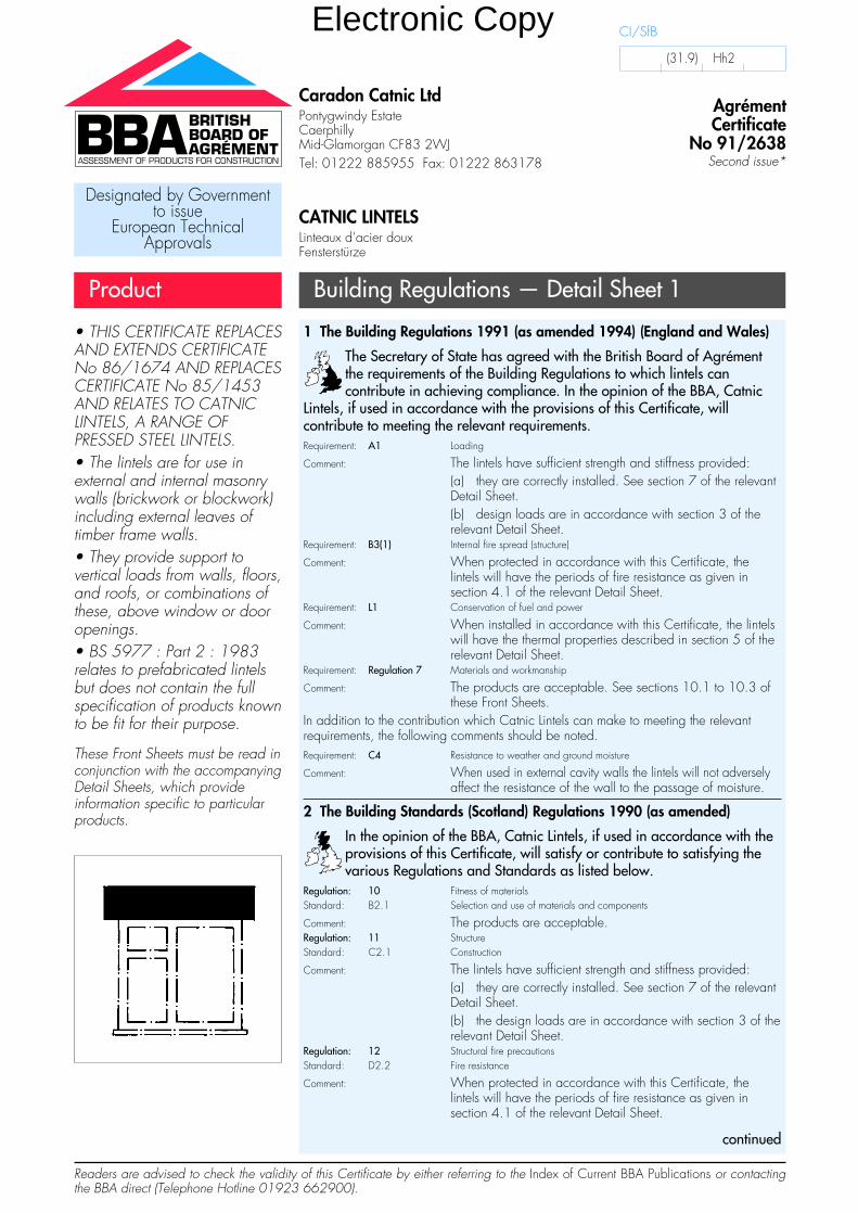
Caradon Catnic LtdPontygwindy EstateCaerphillyMid-Glamorgan CF83 2WJTel: 01222 885955 Fax: 01222 863178
AgrémentCertificate
No 91/2638Second issue*
Designated by Governmentto issue
European TechnicalApprovals
CATNIC LINTELSLinteaux d’acier douxFensterstürze
Product Building Regulations — Detail Sheet 1
• THIS CERTIFICATE REPLACESAND EXTENDS CERTIFICATENo 86/1674 AND REPLACESCERTIFICATE No 85/1453AND RELATES TO CATNICLINTELS, A RANGE OFPRESSED STEEL LINTELS.• The lintels are for use inexternal and internal masonrywalls (brickwork or blockwork)including external leaves oftimber frame walls.• They provide support tovertical loads from walls, floors,and roofs, or combinations ofthese, above window or dooropenings.• BS 5977 : Part 2 : 1983relates to prefabricated lintelsbut does not contain the fullspecification of products knownto be fit for their purpose.
These Front Sheets must be read inconjunction with the accompanyingDetail Sheets, which provideinformation specific to particularproducts.
1 The Building Regulations 1991 (as amended 1994) (England and Wales)
The Secretary of State has agreed with the British Board of Agrémentthe requirements of the Building Regulations to which lintels cancontribute in achieving compliance. In the opinion of the BBA, Catnic
Lintels, if used in accordance with the provisions of this Certificate, willcontribute to meeting the relevant requirements.Requirement: A1 Loading
Comment: The lintels have sufficient strength and stiffness provided:(a) they are correctly installed. See section 7 of the relevantDetail Sheet.(b) design loads are in accordance with section 3 of therelevant Detail Sheet.
Requirement: B3(1) Internal fire spread (structure)
Comment: When protected in accordance with this Certificate, thelintels will have the periods of fire resistance as given insection 4.1 of the relevant Detail Sheet.
Requirement: L1 Conservation of fuel and power
Comment: When installed in accordance with this Certificate, the lintelswill have the thermal properties described in section 5 of therelevant Detail Sheet.
Requirement: Regulation 7 Materials and workmanship
Comment: The products are acceptable. See sections 10.1 to 10.3 ofthese Front Sheets.
In addition to the contribution which Catnic Lintels can make to meeting the relevantrequirements, the following comments should be noted.Requirement: C4 Resistance to weather and ground moisture
Comment: When used in external cavity walls the lintels will not adverselyaffect the resistance of the wall to the passage of moisture.
2 The Building Standards (Scotland) Regulations 1990 (as amended)
In the opinion of the BBA, Catnic Lintels, if used in accordance with theprovisions of this Certificate, will satisfy or contribute to satisfying thevarious Regulations and Standards as listed below.
Regulation: 10 Fitness of materialsStandard: B2.1 Selection and use of materials and components
Comment: The products are acceptable.Regulation: 11 StructureStandard: C2.1 Construction
Comment: The lintels have sufficient strength and stiffness provided:(a) they are correctly installed. See section 7 of the relevantDetail Sheet.(b) the design loads are in accordance with section 3 of therelevant Detail Sheet.
Regulation: 12 Structural fire precautionsStandard: D2.2 Fire resistance
Comment: When protected in accordance with this Certificate, thelintels will have the periods of fire resistance as given insection 4.1 of the relevant Detail Sheet.
continued
Readers are advised to check the validity of this Certificate by either referring to the Index of Current BBA Publications or contactingthe BBA direct (Telephone Hotline 01923 662900).
CI/SfB
(31.9) Hh2
Electronic Copy
Technical Specification
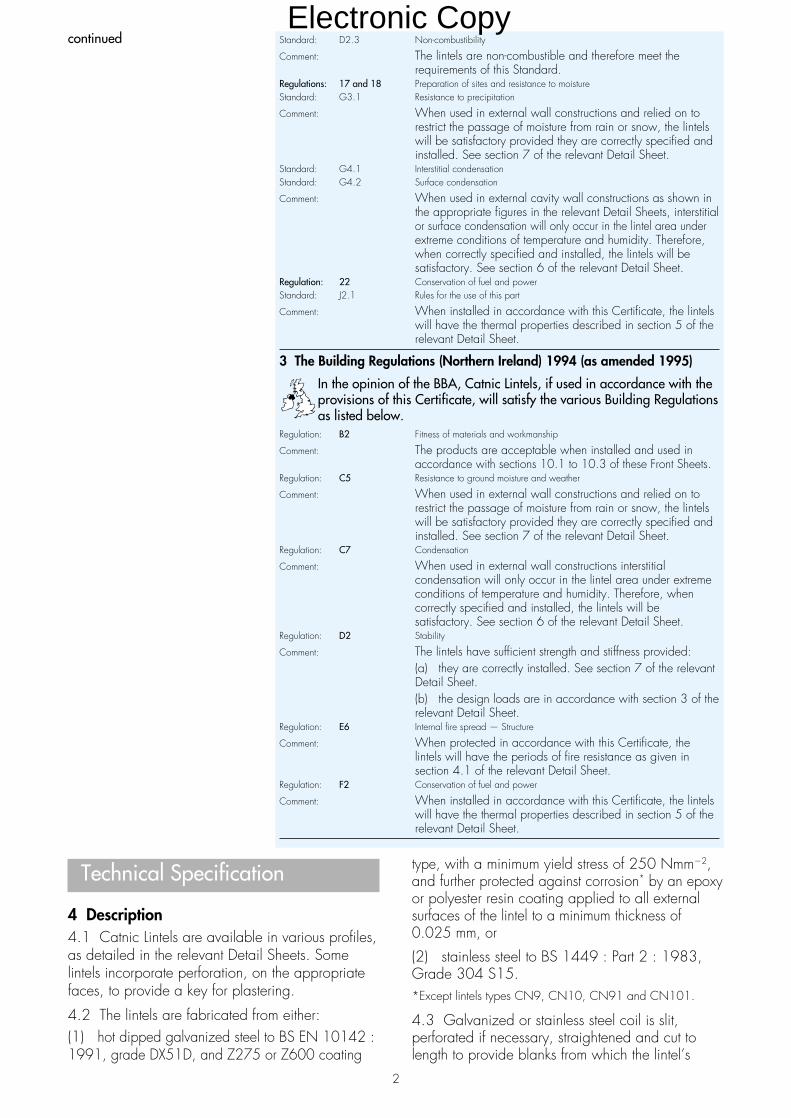
4 Description4.1 Catnic Lintels are available in various profiles,as detailed in the relevant Detail Sheets. Somelintels incorporate perforation, on the appropriatefaces, to provide a key for plastering.
4.2 The lintels are fabricated from either:(1) hot dipped galvanized steel to BS EN 10142 :1991, grade DX51D, and Z275 or Z600 coating
type, with a minimum yield stress of 250 Nmm�2,and further protected against corrosion* by an epoxyor polyester resin coating applied to all externalsurfaces of the lintel to a minimum thickness of0.025 mm, or
(2) stainless steel to BS 1449 : Part 2 : 1983,Grade 304 S15.*Except lintels types CN9, CN10, CN91 and CN101.
4.3 Galvanized or stainless steel coil is slit,perforated if necessary, straightened and cut tolength to provide blanks from which the lintel’s
2
Standard: D2.3 Non-combustibility
Comment: The lintels are non-combustible and therefore meet therequirements of this Standard.
Regulations: 17 and 18 Preparation of sites and resistance to moistureStandard: G3.1 Resistance to precipitation
Comment: When used in external wall constructions and relied on torestrict the passage of moisture from rain or snow, the lintelswill be satisfactory provided they are correctly specified andinstalled. See section 7 of the relevant Detail Sheet.
Standard: G4.1 Interstitial condensationStandard: G4.2 Surface condensation
Comment: When used in external cavity wall constructions as shown inthe appropriate figures in the relevant Detail Sheets, interstitialor surface condensation will only occur in the lintel area underextreme conditions of temperature and humidity. Therefore,when correctly specified and installed, the lintels will besatisfactory. See section 6 of the relevant Detail Sheet.
Regulation: 22 Conservation of fuel and powerStandard: J2.1 Rules for the use of this part
Comment: When installed in accordance with this Certificate, the lintelswill have the thermal properties described in section 5 of therelevant Detail Sheet.
3 The Building Regulations (Northern Ireland) 1994 (as amended 1995)
In the opinion of the BBA, Catnic Lintels, if used in accordance with theprovisions of this Certificate, will satisfy the various Building Regulationsas listed below.
Regulation: B2 Fitness of materials and workmanship
Comment: The products are acceptable when installed and used inaccordance with sections 10.1 to 10.3 of these Front Sheets.
Regulation: C5 Resistance to ground moisture and weather
Comment: When used in external wall constructions and relied on torestrict the passage of moisture from rain or snow, the lintelswill be satisfactory provided they are correctly specified andinstalled. See section 7 of the relevant Detail Sheet.
Regulation: C7 Condensation
Comment: When used in external wall constructions interstitialcondensation will only occur in the lintel area under extremeconditions of temperature and humidity. Therefore, whencorrectly specified and installed, the lintels will besatisfactory. See section 6 of the relevant Detail Sheet.
Regulation: D2 Stability
Comment: The lintels have sufficient strength and stiffness provided:(a) they are correctly installed. See section 7 of the relevantDetail Sheet.(b) the design loads are in accordance with section 3 of therelevant Detail Sheet.
Regulation: E6 Internal fire spread — Structure
Comment: When protected in accordance with this Certificate, thelintels will have the periods of fire resistance as given insection 4.1 of the relevant Detail Sheet.
Regulation: F2 Conservation of fuel and power
Comment: When installed in accordance with this Certificate, the lintelswill have the thermal properties described in section 5 of therelevant Detail Sheet.
continuedElectronic Copy
components are formed by press braking or rollforming. The components are then assembled by spotwelding or press joining to form the completed lintel.
4.4 An epoxy or polyester powder coating isapplied to the galvanized steel lintels’ externalsurfaces and cut edges, and is heat cured.
4.5 Quality control checks include:incoming steelchemical compositiondimensional tolerancemechanical propertiesthicknessquality of galvanizing.
during manufacturedimensionsweld qualitythicknessquality of the resin coating.
5 Delivery and site handling5.1 The lintels are delivered to site or to builders’merchants singly or in bundles carrying a labelbearing the manufacturer’s name and the BBAidentification mark incorporating the number of thisCertificate.
5.2 Reasonable care must be taken duringunloading, stacking and storage to avoiddamaging the protective coating. Lintels that havesuffered deformation or major damage to theprotective coating must not be used; minor damageto the coating must be repaired by usingcompatible epoxy or polyester resin coatings.
5.3 The lintels must be stored off the ground toavoid the risk of either mechanical damage orcontamination by corrosive substances.
5.4 When lifting or carrying, consideration mustbe given to the size and weight of the product (seemanufacturer’s brochure).
Design Data
6 GeneralCatnic Lintels are satisfactory for use in internalwalls, at external cavity or solid walls of brickworkand/or blockwork to provide support to wall, roofor floor loads (or a combination of these) abovewindow or door openings.
7 Practicability of installation7.1 The lintels are installed easily by methodscommonly used in building practice.
7.2 The lintels are lighter than conventionalconcrete lintels and can be positioned by one ortwo operatives.
7.3 The galvanized epoxy powder or galvanizedpolyester coated steel lintels obviate the need for aseparate damp-proof tray at the lintel position.
7.4 The use of stopends and weep holes to thelintels should be incorporated as recommended inBS 5628 : Part 3 : 1985.
7.5 When correctly installed, the curtain trackfixing clips provide adequate support; installationcan be carried out easily.
7.6 Where relevant, the perforated steel lintel soffitfaces and insulated surfaces provide a suitablesubstrate for plastering.
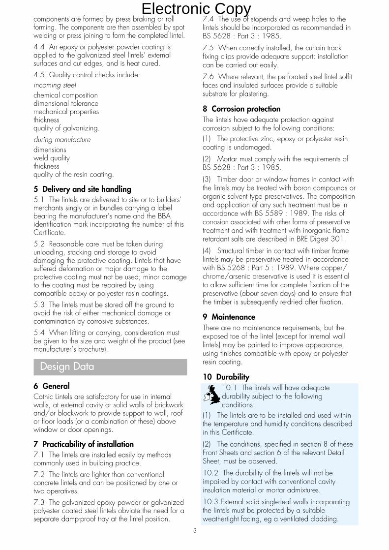
8 Corrosion protectionThe lintels have adequate protection againstcorrosion subject to the following conditions:(1) The protective zinc, epoxy or polyester resincoating is undamaged.
(2) Mortar must comply with the requirements ofBS 5628 : Part 3 : 1985.
(3) Timber door or window frames in contact withthe lintels may be treated with boron compounds ororganic solvent type preservatives. The compositionand application of any such treatment must be inaccordance with BS 5589 : 1989. The risks ofcorrosion associated with other forms of preservativetreatment and with treatment with inorganic flameretardant salts are described in BRE Digest 301.
(4) Structural timber in contact with timber framelintels may be preservative treated in accordancewith BS 5268 : Part 5 : 1989. Where copper/chrome/arsenic preservative is used it is essentialto allow sufficient time for complete fixation of thepreservative (about seven days) and to ensure thatthe timber is subsequently re-dried after fixation.
9 MaintenanceThere are no maintenance requirements, but theexposed toe of the lintel (except for internal walllintels) may be painted to improve appearance,using finishes compatible with epoxy or polyesterresin coating.
10 Durability10.1 The lintels will have adequatedurability subject to the followingconditions:
(1) The lintels are to be installed and used withinthe temperature and humidity conditions describedin this Certificate.
(2) The conditions, specified in section 8 of theseFront Sheets and section 6 of the relevant DetailSheet, must be observed.
10.2 The durability of the lintels will not beimpaired by contact with conventional cavityinsulation material or mortar admixtures.
10.3 External solid single-leaf walls incorporatingthe lintels must be protected by a suitableweathertight facing, eg a ventilated cladding.
3
Electronic Copy
In the opinion of the British Board of Agrément, Catnic Lintels are fit for their intended use providedthey are installed, used and maintained as set out in this Certificate. Certificate No 91/2638 isaccordingly awarded to Caradon Catnic Ltd.
On behalf of the British Board of Agrément
Date of Second issue: 6th February 1997 Director
*Original Certificate issued 28th March 1991. This amended version includes change of name of Certificate holderand references to the revised Building Regulations and associated text.
British Board of AgrémentP O Box No 195, Bucknalls LaneGarston, Watford, Herts WD2 7NGFax: 01923 662133 ©1997
For technical or additionalinformation, tel: 01923 670844.For information about AgrémentCertificate validity and scope, tel:Hotline: 01923 662900
Bibliography
BS 1449 Steel plate, sheet and stripPart 2 : 1983 Specification for stainless steel andheat-resisting steel plate, sheet and strip
BS 5268 Structural use of timberPart 5 : 1989 Code of practice for thepreservative treatment of structural timber
BS 5589 : 1989 Code of practice forpreservation of timberBS 5628 Code of practice for use of masonry
Part 3 : 1985 Materials and components, designand workmanship
BS EN 10142 : 1991 Specification for continuouslyhot-dip zinc coated low carbon steel sheet andstrip for cold forming: technical delivery conditionsBRE Digest 301 : 1985 Corrosion of metals bywood
Conditions of Certification
11 Conditions11.1 Where reference is made in this Certificateto any Act of Parliament, Regulation madethereunder, Statutory Instrument, Code of Practice,British Standard, manufacturer’s instruction orsimilar publication, it shall be construed asreference to such publication in the form in which itis in force at the date of this Certificate.
11.2 The quality of materials and the method ofmanufacture have been examined and foundsatisfactory by the BBA and must be maintained tothis standard during the period of validity of this
Certificate. This Certificate will remain valid for anunlimited period provided:(a) the specification of the product is unchanged;and(b) the manufacturer continues to have the productchecked by the BBA.
11.3 This Certificate will apply only to the productthat is installed, used and maintained as set out inthis Certificate.
11.4 In granting this Certificate, the BBA makesno representation as to:(a) the presence or absence of patent or similarrights subsisting in the product; and(b) the legal right of the Certificate holder tomarket, install or maintain the product; and(c) the nature of individual installations of theproduct, including methods and workmanship.
11.5 It should be noted that any recommendationsrelating to the safe use of this product which arecontained or referred to in this Certificate are theminimum standards required to be met when theproduct is used. They do not purport in any way torestate the requirements of the Health & Safety atWork etc Act 1974, or of any other statutory orCommon Law duties of care, or of any duty of carewhich exist at the date of this Certificate or in thefuture; nor is conformity with such recommendationsto be taken as satisfying the requirements of the1974 Act or of any present or future statutory orCommon Law duties of care. In granting thisCertificate, the BBA does not accept responsibilityto any person or body for any loss or damage,including personal injury, arising as a direct orindirect result of the use of this product.
Electronic Copy
Readers are advised to check the validity of this Detail Sheet by either referring to the Index of Current BBA Publications or contactingthe BBA direct (Telephone Hotline 01923 662900).
Technical Specification
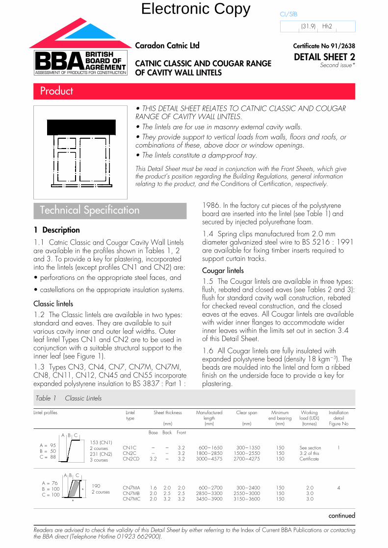
1 Description1.1 Catnic Classic and Cougar Cavity Wall Lintelsare available in the profiles shown in Tables 1, 2and 3. To provide a key for plastering, incorporatedinto the lintels (except profiles CN1 and CN2) are:• perforations on the appropriate steel faces, and
• castellations on the appropriate insulation systems.
Classic lintels1.2 The Classic lintels are available in two types:standard and eaves. They are available to suitvarious cavity inner and outer leaf widths. Outerleaf lintel Types CN1 and CN2 are to be used inconjunction with a suitable structural support to theinner leaf (see Figure 1).1.3 Types CN3, CN4, CN7, CN7M, CN7MI,CN8, CN11, CN12, CN45 and CN55 incorporateexpanded polystyrene insulation to BS 3837 : Part 1 :
1986. In the factory cut pieces of the polystyreneboard are inserted into the lintel (see Table 1) andsecured by injected polyurethane foam.
1.4 Spring clips manufactured from 2.0 mmdiameter galvanized steel wire to BS 5216 : 1991are available for fixing timber inserts required tosupport curtain tracks.
Cougar lintels1.5 The Cougar lintels are available in three types:flush, rebated and closed eaves (see Tables 2 and 3):flush for standard cavity wall construction, rebatedfor checked reveal construction, and the closedeaves at the eaves. All Cougar lintels are availablewith wider inner flanges to accommodate widerinner leaves within the limits set out in section 3.4of this Detail Sheet.
1.6 All Cougar lintels are fully insulated withexpanded polystyrene bead (density 18 kgm�3). Thebeads are moulded into the lintel and form a ribbedfinish on the underside face to provide a key forplastering.
• THIS DETAIL SHEET RELATES TO CATNIC CLASSIC AND COUGARRANGE OF CAVITY WALL LINTELS.• The lintels are for use in masonry external cavity walls.• They provide support to vertical loads from walls, floors and roofs, orcombinations of these, above door or window openings.• The lintels constitute a damp-proof tray.
This Detail Sheet must be read in conjunction with the Front Sheets, which givethe product’s position regarding the Building Regulations, general informationrelating to the product, and the Conditions of Certification, respectively.
Certificate No 91/2638
DETAIL SHEET 2Second issue*
Caradon Catnic Ltd
CATNIC CLASSIC AND COUGAR RANGE OF CAVITY WALL LINTELS
Product
CI/SfB
(31.9) Hh2
Table 1 Classic Lintels
Lintel profiles Lintel Sheet thickness Manufactured Clear span Minimum Working Installationtype length end bearing load (UDL) detail
(mm) (mm) (mm) (mm) (tonnes) Figure No
Base Back Front
CN1C � � 3.2 600�1650 300�1350 150 See section 1CN2C � � 3.2 1800�2850 1500�2550 150 3.2 of thisCN2CD 3.2 � 3.2 3000�4575 2700�4275 150 Certificate
CN7MA 1.6 2.0 2.0 600�2700 300�2400 150 2.0 4CN7MB 2.0 2.5 2.5 2850�3300 2550�3000 150 3.0CN7MC 2.0 3.2 3.2 3450�3900 3150�3600 150 3.0
continued
A B C
A = 95B = 50C = 88
153 (CN1)2 courses231 (CN2)3 courses
A B C
A = 76B = 100C = 100
1902 courses*
*
Electronic Copy
Lintel profiles Lintel Sheet thickness Manufactured Clear span Minimum Working Installationtype length end bearing load (UDL) detail
(mm) (mm) (mm) (mm) (tonnes) Figure No
Base Back Front
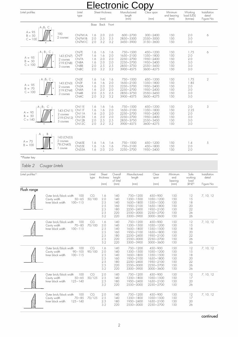
CN7M1A 1.6 2.0 2.0 600�2700 300�2400 150 2.0 6CN7M1B 2.0 2.5 2.5 2850�3300 2550�3000 150 3.0CN7M1C 2.0 3.2 3.2 3450�3900 3150�3600 150 3.0
CN7E 1.6 1.6 1.6 750�1500 450�1200 150 1.75 6CN7F 1.6 1.6 2.0 1650�2100 1350�1800 150 2.0CN7A 1.6 2.0 2.0 2250�2700 1950�2400 150 2.0CN8A 1.6 2.0 2.0 2250�2700 1950�2400 150 3.0CN8B 2.0 2.5 2.5 2850�3750 2550�3450 150 3.0CN8C 2.0 3.2 3.2 3900�4575 3600�4275 150 3.0
CN3E 1.6 1.6 1.6 750�1500 450�1200 150 1.75 2CN3F 1.6 1.6 2.0 1650�2100 1350�1800 150 1.85CN3A 1.6 2.0 2.0 2250�2700 1950�2400 150 2.0CN4A 1.6 2.0 2.0 2250�2700 1950�2400 150 3.0CN4B 2.0 2.5 2.5 2850�3750 2550�3450 150 3.0CN4C 2.0 3.2 3.2 3900�4575 3600�4275 150 3.0
CN11E 1.6 1.6 1.6 750�1500 450�1200 150 2.0 3CN11F 1.6 1.6 2.0 1650�2100 1350�1800 150 2.25CN11A 1.6 2.0 2.0 2250�2700 1950�2400 150 2.0CN12A 1.6 2.0 2.0 2250�2700 1950�2400 150 3.0CN12B 2.0 2.5 2.5 2850�3750 2550�3450 150 3.0CN12C 2.0 3.2 3.2 3900�4575 3600�4275 150 3.0
CN45E 1.6 1.6 1.6 750�1500 450�1200 150 1.4 5CN55E 1.6 1.6 1.6 750�2100 450�1800 150 2.0CN55A 1.6 2.0 2.0 2250�2700 1950�2400 150 2.0
*Plaster key
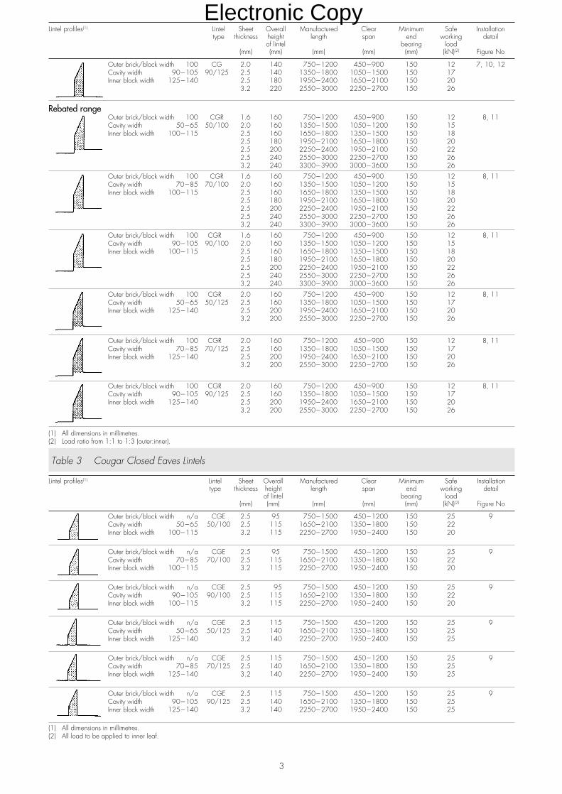
Table 2 Cougar Lintels
Lintel profiles(1) Lintel Sheet Overall Manufactured Clear Minimum Safe Installationtype thickness height length span end working detail
of lintel bearing load(mm) (mm) (mm) (mm) (mm) (kN)(2) Figure No
Flush range
Outer brick/block width 100 CG 1.6 140 750�1200 450�900 150 12 7, 10, 12Cavity width 50�65 50/100 2.0 140 1350�1500 1050�1200 150 15Inner block width 100�115 2.5 140 1650�1800 1350�1500 150 18
2.5 160 1950�2100 1650�1800 150 202.5 180 2250�2400 1950�2100 150 222.5 220 2550�3000 2250�2700 150 263.2 220 3300�3900 3000�3600 150 26
Outer brick/block width 100 CG 1.6 140 750�1200 450�900 150 12 7, 10, 12Cavity width 70�85 70/100 2.0 140 1350�1500 1050�1200 150 15Inner block width 100�115 2.5 140 1650�1800 1350�1500 150 18
2.5 160 1950�2100 1650�1800 150 202.5 180 2250�2400 1950�2100 150 222.5 220 2550�3000 2250�2700 150 263.2 220 3300�3900 3000�3600 150 26
Outer brick/block width 100 CG 1.6 140 750�1200 450�900 150 12 7, 10, 12Cavity width 90�105 90/100 2.0 140 1350�1500 1050�1200 150 15Inner block width 100�115 2.5 140 1650�1800 1350�1500 150 18
2.5 160 1950�2100 1650�1800 150 202.5 180 2250�2400 1950�2100 150 222.5 220 2550�3000 2250�2700 150 263.2 220 3300�3900 3000�3600 150 26
Outer brick/block width 100 CG 2.0 140 750�1200 450�900 150 12 7, 10, 12Cavity width 50�65 50/125 2.5 140 1350�1800 1050�1500 150 17Inner block width 125�140 2.5 180 1950�2400 1650�2100 150 20
3.2 220 2550�3000 2250�2700 150 26
Outer brick/block width 100 CG 2.0 140 750�1200 450�900 150 12 7, 10, 12Cavity width 70�85 70/125 2.5 140 1350�1800 1050�1500 150 17Inner block width 125�140 2.5 180 1950�2400 1650�2100 150 20
3.2 220 2550�3000 2250�2700 150 26
continued
2
A B C
A = 95B = 50C = 100
1902 courses*
*
A B C
A = 95B = 50C = 100
143 (CN7)2 courses219 (CN8)3 courses
*
*
A B C
A = 95B = 70C = 100
143 (CN3)2 courses219 (CN4)3 courses
*
*
A B C
A = 95B = 50C = 140
143 (CN11)2 courses219 (CN12)3 courses
*
*
A B
A = 75B = 100
143 (CN55)2 courses78 (CN45)1 course
*
*
Electronic Copy
Lintel profiles(1) Lintel Sheet Overall Manufactured Clear Minimum Safe Installationtype thickness height length span end working detail
of lintel bearing load(mm) (mm) (mm) (mm) (mm) (kN)(2) Figure No
Outer brick/block width 100 CG 2.0 140 750�1200 450�900 150 12 7, 10, 12Cavity width 90�105 90/125 2.5 140 1350�1800 1050�1500 150 17Inner block width 125�140 2.5 180 1950�2400 1650�2100 150 20
3.2 220 2550�3000 2250�2700 150 26
Rebated rangeOuter brick/block width 100 CGR 1.6 160 750�1200 450�900 150 12 8, 11Cavity width 50�65 50/100 2.0 160 1350�1500 1050�1200 150 15Inner block width 100�115 2.5 160 1650�1800 1350�1500 150 18
2.5 180 1950�2100 1650�1800 150 202.5 200 2250�2400 1950�2100 150 222.5 240 2550�3000 2250�2700 150 263.2 240 3300�3900 3000�3600 150 26
Outer brick/block width 100 CGR 1.6 160 750�1200 450�900 150 12 8, 11Cavity width 70�85 70/100 2.0 160 1350�1500 1050�1200 150 15Inner block width 100�115 2.5 160 1650�1800 1350�1500 150 18
2.5 180 1950�2100 1650�1800 150 202.5 200 2250�2400 1950�2100 150 222.5 240 2550�3000 2250�2700 150 263.2 240 3300�3900 3000�3600 150 26
Outer brick/block width 100 CGR 1.6 160 750�1200 450�900 150 12 8, 11Cavity width 90�105 90/100 2.0 160 1350�1500 1050�1200 150 15Inner block width 100�115 2.5 160 1650�1800 1350�1500 150 18
2.5 180 1950�2100 1650�1800 150 202.5 200 2250�2400 1950�2100 150 222.5 240 2550�3000 2250�2700 150 263.2 240 3300�3900 3000�3600 150 26
Outer brick/block width 100 CGR 2.0 160 750�1200 450�900 150 12 8, 11Cavity width 50�65 50/125 2.5 160 1350�1800 1050�1500 150 17Inner block width 125�140 2.5 200 1950�2400 1650�2100 150 20
3.2 200 2550�3000 2250�2700 150 26
Outer brick/block width 100 CGR 2.0 160 750�1200 450�900 150 12 8, 11Cavity width 70�85 70/125 2.5 160 1350�1800 1050�1500 150 17Inner block width 125�140 2.5 200 1950�2400 1650�2100 150 20
3.2 200 2550�3000 2250�2700 150 26
Outer brick/block width 100 CGR 2.0 160 750�1200 450�900 150 12 8, 11Cavity width 90�105 90/125 2.5 160 1350�1800 1050�1500 150 17Inner block width 125�140 2.5 200 1950�2400 1650�2100 150 20
3.2 200 2550�3000 2250�2700 150 26
(1) All dimensions in millimetres.(2) Load ratio from 1:1 to 1:3 (outer:inner).
Table 3 Cougar Closed Eaves Lintels
Lintel profiles(1) Lintel Sheet Overall Manufactured Clear Minimum Safe Installationtype thickness height length span end working detail
of lintel bearing load(mm) (mm) (mm) (mm) (mm) (kN)(2) Figure No
Outer brick/block width n/a CGE 2.5 95 750�1500 450�1200 150 25 9Cavity width 50�65 50/100 2.5 115 1650�2100 1350�1800 150 22Inner block width 100�115 3.2 115 2250�2700 1950�2400 150 20
Outer brick/block width n/a CGE 2.5 95 750�1500 450�1200 150 25 9Cavity width 70�85 70/100 2.5 115 1650�2100 1350�1800 150 22Inner block width 100�115 3.2 115 2250�2700 1950�2400 150 20
Outer brick/block width n/a CGE 2.5 95 750�1500 450�1200 150 25 9Cavity width 90�105 90/100 2.5 115 1650�2100 1350�1800 150 22Inner block width 100�115 3.2 115 2250�2700 1950�2400 150 20
Outer brick/block width n/a CGE 2.5 115 750�1500 450�1200 150 25 9Cavity width 50�65 50/125 2.5 140 1650�2100 1350�1800 150 25Inner block width 125�140 3.2 140 2250�2700 1950�2400 150 25
Outer brick/block width n/a CGE 2.5 115 750�1500 450�1200 150 25 9Cavity width 70�85 70/125 2.5 140 1650�2100 1350�1800 150 25Inner block width 125�140 3.2 140 2250�2700 1950�2400 150 25
Outer brick/block width n/a CGE 2.5 115 750�1500 450�1200 150 25 9Cavity width 90�105 90/125 2.5 140 1650�2100 1350�1800 150 25Inner block width 125�140 3.2 140 2250�2700 1950�2400 150 25
(1) All dimensions in millimetres.(2) All load to be applied to inner leaf.
3
Electronic Copy
4
Design Data
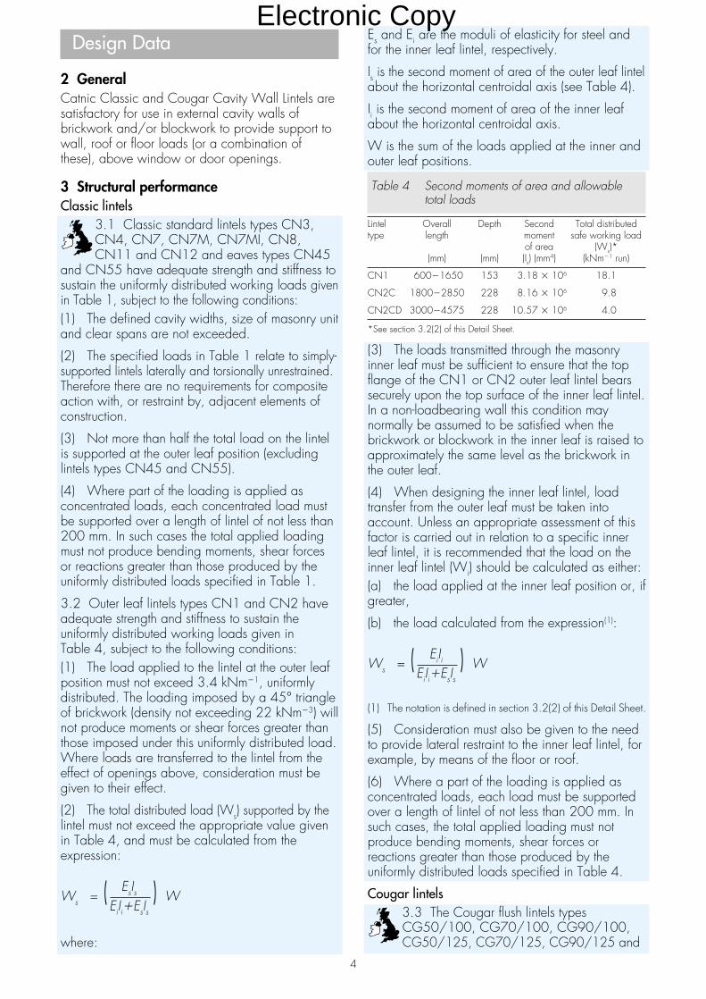
2 GeneralCatnic Classic and Cougar Cavity Wall Lintels aresatisfactory for use in external cavity walls ofbrickwork and/or blockwork to provide support towall, roof or floor loads (or a combination ofthese), above window or door openings.
3 Structural performanceClassic lintels
3.1 Classic standard lintels types CN3,CN4, CN7, CN7M, CN7MI, CN8,CN11 and CN12 and eaves types CN45
and CN55 have adequate strength and stiffness tosustain the uniformly distributed working loads givenin Table 1, subject to the following conditions:(1) The defined cavity widths, size of masonry unitand clear spans are not exceeded.
(2) The specified loads in Table 1 relate to simply-supported lintels laterally and torsionally unrestrained.Therefore there are no requirements for compositeaction with, or restraint by, adjacent elements ofconstruction.
(3) Not more than half the total load on the lintelis supported at the outer leaf position (excludinglintels types CN45 and CN55).
(4) Where part of the loading is applied asconcentrated loads, each concentrated load mustbe supported over a length of lintel of not less than200 mm. In such cases the total applied loadingmust not produce bending moments, shear forcesor reactions greater than those produced by theuniformly distributed loads specified in Table 1.
3.2 Outer leaf lintels types CN1 and CN2 haveadequate strength and stiffness to sustain theuniformly distributed working loads given inTable 4, subject to the following conditions:(1) The load applied to the lintel at the outer leafposition must not exceed 3.4 kNm�1, uniformlydistributed. The loading imposed by a 45° triangleof brickwork (density not exceeding 22 kNm�3) willnot produce moments or shear forces greater thanthose imposed under this uniformly distributed load.Where loads are transferred to the lintel from theeffect of openings above, consideration must begiven to their effect.
(2) The total distributed load (Ws) supported by thelintel must not exceed the appropriate value givenin Table 4, and must be calculated from theexpression:
EsIsWs = ( ) WEiIi�EsIs
where:
Es and Ei are the moduli of elasticity for steel andfor the inner leaf lintel, respectively.
Is is the second moment of area of the outer leaf lintelabout the horizontal centroidal axis (see Table 4).
Ii is the second moment of area of the inner leafabout the horizontal centroidal axis.
W is the sum of the loads applied at the inner andouter leaf positions.
Table 4 Second moments of area and allowabletotal loads
Lintel Overall Depth Second Total distributedtype length moment safe working load
of area (Ws)*(mm) (mm) (Is) (mm4) (kNm�1 run)
CN1 600�1650 153 3.18 � 106 18.1
CN2C 1800�2850 228 8.16 � 106 9.8
CN2CD 3000�4575 228 10.57 � 106 4.0
*See section 3.2(2) of this Detail Sheet.
(3) The loads transmitted through the masonryinner leaf must be sufficient to ensure that the topflange of the CN1 or CN2 outer leaf lintel bearssecurely upon the top surface of the inner leaf lintel.In a non-loadbearing wall this condition maynormally be assumed to be satisfied when thebrickwork or blockwork in the inner leaf is raised toapproximately the same level as the brickwork inthe outer leaf.
(4) When designing the inner leaf lintel, loadtransfer from the outer leaf must be taken intoaccount. Unless an appropriate assessment of thisfactor is carried out in relation to a specific innerleaf lintel, it is recommended that the load on theinner leaf lintel (Wi) should be calculated as either:(a) the load applied at the inner leaf position or, ifgreater,
(b) the load calculated from the expression(1):
EiIiWs = ( ) WEiIi�EsIs
(1) The notation is defined in section 3.2(2) of this Detail Sheet.
(5) Consideration must also be given to the needto provide lateral restraint to the inner leaf lintel, forexample, by means of the floor or roof.
(6) Where a part of the loading is applied asconcentrated loads, each load must be supportedover a length of lintel of not less than 200 mm. Insuch cases, the total applied loading must notproduce bending moments, shear forces orreactions greater than those produced by theuniformly distributed loads specified in Table 4.
Cougar lintels3.3 The Cougar flush lintels typesCG50/100, CG70/100, CG90/100,CG50/125, CG70/125, CG90/125 and
Electronic Copy

5
Cougar rebated lintels CGR50/100, CGR70/100,CGR90/100, CGR50/125, CGR70/125, andCGR90/125, have adequate strength and stiffnessto sustain the uniformly distributed working loadsgiven in Table 2, subject to the following conditions:(1) The defined cavity width, size of masonry unitand clear spans are not exceeded.
(2) Not more than half of the total load on thelintel is supported at the outer leaf position.
(3) The specified loads in Table 2 relate to simply-supported lintels laterally and torsionally unrestrained.Therefore there are no requirements for compositeaction with, or restraint by, adjacent elements ofconstruction.
(4) Where part of the loading is applied asconcentrated loads, each concentrated load mustbe over a length of not less than 200 mm. In suchcases the total applied loading must not producebending moments, shear forces or reactions greaterthan those produced by the uniformly distributedloads specified in Table 1.
Cougar closed eaves lintels3.4 The Cougar closed eaves lintels typesCGE50/100, CGE70/100, CGE90/100,CGE50/125, CGE70/125 and CGE90/125have adequate strength and stiffness to sustain theuniformly distributed loads given in Table 4, subjectto the following conditions:(1) The defined cavity width, size of masonry unitand clear spans are not exceeded.
(2) The specified loads in Table 3 relate to lintelslaterally and torsionally restrained as shown inFigure 10. Therefore it is imperative that theconstruction above the lintels comprising blockworkand timber wallplate is fully cured prior to theapplication of further roof loads.(3) The specified loads given in Table 3 are to beapplied to the inner leaf position only.
(4) Where part of the loading is applied asconcentrated loads, each load must be supportedover a length of lintel of not less than 200 mm. Insuch cases the total applied loading must notproduce bending moments, shear forces orreactions greater than those produced by theuniformly distributed loads specified in Table 3.
General3.5 In addition to the requirements specificallyreferred to in this Certificate, structures of brickworkor blockwork in which the lintels are incorporatedmust be designed and constructed to comply withthe following technical specifications, as appropriate:(1) BS 5628 : Part 1 : 1992 and BS 5628 :Part 3 : 1985.
(2) Section 1, Part C of Approved Document A1/2to the Building Regulations 1991 (as amended1994) (England and Wales).
(3) Small Buildings Guide for compliance withPart C of the Building Standards (Scotland)Regulations 1990 (as amended).
(4) Section 3 of DoE (NI) Technical Booklet D :1994 Structure.
3.6 Guidance for the assessment of loads onlintels in masonry is given in BS 5977 : Part 1 :1981(1986).
4 Behaviour in relation to fire4.1 The construction details shown in Figures1 to 5, 7 to 9, and 12 have been assessed ascapable of satisfying the Building Regulations
1991 (as amended 1994) (England and Wales), theBuilding Standards (Scotland) Regulations 1990 (asamended) and the Building Regulations (NorthernIreland) 1994 (as amended 1995) in situationswhere a one-hour fire resistance is required.
4.2 Where any other form of wall constructionincorporating the lintels is subject to fire resistancerequirements, an appropriate assessment or testmust be carried out by a National MeasurementAccreditation Service (NAMAS)(1) accreditedlaboratory for the test concerned.(1) NAMAS is now part of the United Kingdom AccreditationService (UKAS).
5 Thermal transmittanceEvaluated constructions
5.1 The construction details containingCougar flush lintels types CG50/100,CG70/100, CG90/100, CG50/125,
CG70/125 and CG90/125 (see Figure 7) andCougar rebated lintels types CGR50/100,CGR70/100, CGR90/100, CGR50/125,CGR70/125 and CGR90/125 (see Figure 8),are similar to the partial cavity fill lintel detail shownin Diagrams 3 and 7 of Approved Document L ofthe Building Regulations 1991 (as amended 1994)(England and Wales) and therefore aresatisfactory. The construction details containingClassic lintels types CN3, CN4, CN7, CN7M,CNM7I, CN8, CN11, CN12, CN45 andCN55 (see Figures 2 to 6) and Cougar closedeaves lintels types CGE50/100, CGE70/100,CGE90/100, CGE50/125, CGE70/125 andCGE90/125 (see Figure 9), were evaluated todetermine their likely hygrothermal performance.
5.2 Example details were modelled numerically todetermine the heat loss due to thermal bridgingand the results compared to those obtained for thebox and other lintels details given in Diagrams 3and 7 of the Approved Document L for which theadditional heat loss may be ignored. The analysisshowed that for details shown in Figures 2 to 6 theadditional heat loss will be similar to that whichcould be expected for the satisfactory detail, andfor Figure 9 it will be lower. Other details using thelintels, where the U value of the basic wall
Electronic Copy
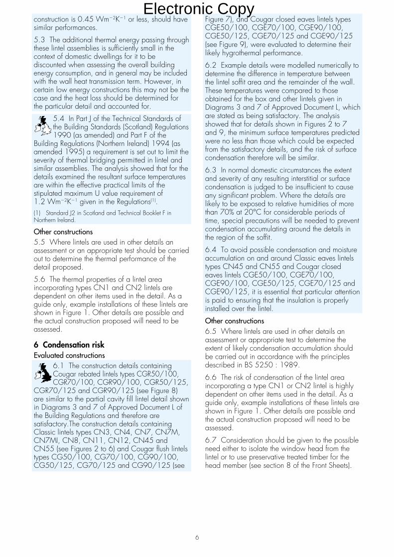
construction is 0.45 Wm�2K�1 or less, should havesimilar performances.
5.3 The additional thermal energy passing throughthese lintel assemblies is sufficiently small in thecontext of domestic dwellings for it to bediscounted when assessing the overall buildingenergy consumption, and in general may be includedwith the wall heat transmission term. However, incertain low energy constructions this may not be thecase and the heat loss should be determined forthe particular detail and accounted for.
5.4 In Part J of the Technical Standards ofthe Building Standards (Scotland) Regulations1990 (as amended) and Part F of the
Building Regulations (Northern Ireland) 1994 (asamended 1995) a requirement is set out to limit theseverity of thermal bridging permitted in lintel andsimilar assemblies. The analysis showed that for thedetails examined the resultant surface temperaturesare within the effective practical limits of thestipulated maximum U value requirement of1.2 Wm�2K�1 given in the Regulations(1).(1) Standard J2 in Scotland and Technical Booklet F inNorthern Ireland.
Other constructions5.5 Where lintels are used in other details anassessment or an appropriate test should be carriedout to determine the thermal performance of thedetail proposed.
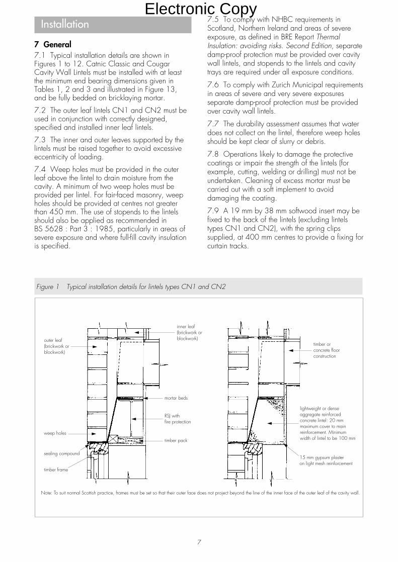
5.6 The thermal properties of a lintel areaincorporating types CN1 and CN2 lintels aredependent on other items used in the detail. As aguide only, example installations of these lintels areshown in Figure 1. Other details are possible andthe actual construction proposed will need to beassessed.
6 Condensation riskEvaluated constructions
6.1 The construction details containingCougar rebated lintels types CGR50/100,CGR70/100, CGR90/100, CGR50/125,
CGR70/125 and CGR90/125 (see Figure 8)are similar to the partial cavity fill lintel detail shownin Diagrams 3 and 7 of Approved Document L ofthe Building Regulations and therefore aresatisfactory.The construction details containingClassic lintels types CN3, CN4, CN7, CN7M,CN7MI, CN8, CN11, CN12, CN45 andCN55 (see Figures 2 to 6) and Cougar flush lintelstypes CG50/100, CG70/100, CG90/100,CG50/125, CG70/125 and CG90/125 (see
Figure 7), and Cougar closed eaves lintels typesCGE50/100, CGE70/100, CGE90/100,CGE50/125, CGE70/125 and CGE90/125(see Figure 9), were evaluated to determine theirlikely hygrothermal performance.
6.2 Example details were modelled numerically todetermine the difference in temperature betweenthe lintel soffit area and the remainder of the wall.These temperatures were compared to thoseobtained for the box and other lintels given inDiagrams 3 and 7 of Approved Document L, whichare stated as being satisfactory. The analysisshowed that for details shown in Figures 2 to 7and 9, the minimum surface temperatures predictedwere no less than those which could be expectedfrom the satisfactory details, and the risk of surfacecondensation therefore will be similar.
6.3 In normal domestic circumstances the extentand severity of any resulting interstitial or surfacecondensation is judged to be insufficient to causeany significant problem. Where the details arelikely to be exposed to relative humidities of morethan 70% at 20°C for considerable periods oftime, special precautions will be needed to preventcondensation accumulating around the details inthe region of the soffit.
6.4 To avoid possible condensation and moistureaccumulation on and around Classic eaves lintelstypes CN45 and CN55 and Cougar closedeaves lintels CGE50/100, CGE70/100,CGE90/100, CGE50/125, CGE70/125 andCGE90/125, it is essential that particular attentionis paid to ensuring that the insulation is properlyinstalled over the lintel.
Other constructions6.5 Where lintels are used in other details anassessment or appropriate test to determine theextent of likely condensation accumulation shouldbe carried out in accordance with the principlesdescribed in BS 5250 : 1989.
6.6 The risk of condensation of the lintel areaincorporating a type CN1 or CN2 lintel is highlydependent on other items used in the detail. As aguide only, example installations of these lintels areshown in Figure 1. Other details are possible andthe actual construction proposed will need to beassessed.
6.7 Consideration should be given to the possibleneed either to isolate the window head from thelintel or to use preservative treated timber for thehead member (see section 8 of the Front Sheets).
6
Electronic Copy
7
Installation
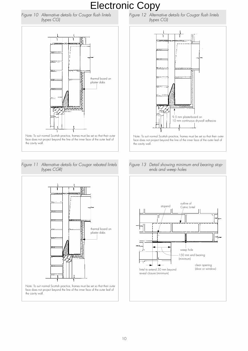
7 General7.1 Typical installation details are shown inFigures 1 to 12. Catnic Classic and CougarCavity Wall Lintels must be installed with at leastthe minimum end bearing dimensions given inTables 1, 2 and 3 and illustrated in Figure 13,and be fully bedded on bricklaying mortar.
7.2 The outer leaf lintels CN1 and CN2 must beused in conjunction with correctly designed,specified and installed inner leaf lintels.
7.3 The inner and outer leaves supported by thelintels must be raised together to avoid excessiveeccentricity of loading.
7.4 Weep holes must be provided in the outerleaf above the lintel to drain moisture from thecavity. A minimum of two weep holes must beprovided per lintel. For fair-faced masonry, weepholes should be provided at centres not greaterthan 450 mm. The use of stopends to the lintelsshould also be applied as recommended inBS 5628 : Part 3 : 1985, particularly in areas ofsevere exposure and where full-fill cavity insulationis specified.
7.5 To comply with NHBC requirements inScotland, Northern Ireland and areas of severeexposure, as defined in BRE Report ThermalInsulation: avoiding risks. Second Edition, separatedamp-proof protection must be provided over cavitywall lintels, and stopends to the lintels and cavitytrays are required under all exposure conditions.
7.6 To comply with Zurich Municipal requirementsin areas of severe and very severe exposuresseparate damp-proof protection must be providedover cavity wall lintels.
7.7 The durability assessment assumes that waterdoes not collect on the lintel, therefore weep holesshould be kept clear of slurry or debris.
7.8 Operations likely to damage the protectivecoatings or impair the strength of the lintels (forexample, cutting, welding or drilling) must not beundertaken. Cleaning of excess mortar must becarried out with a soft implement to avoiddamaging the coating.
7.9 A 19 mm by 38 mm softwood insert may befixed to the back of the lintels (excluding lintelstypes CN1 and CN2), with the spring clipssupplied, at 400 mm centres to provide a fixing forcurtain tracks.
Figure 1 Typical installation details for lintels types CN1 and CN2
Electronic Copy
8
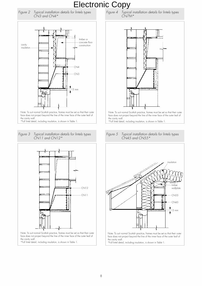
Figure 2 Typical installation details for lintels typesCN3 and CN4*
Figure 3 Typical installation details for lintels typesCN11 and CN12*
Figure 4 Typical installation details for lintels typesCN7M*
Figure 5 Typical installation details for lintels typesCN45 and CN55*
Electronic Copy
9
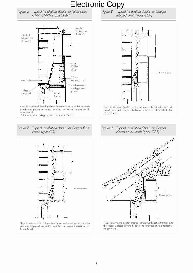
Figure 6 Typical installation details for lintels typesCN7, CN7M1 and CN8*
Figure 7 Typical installation details for Cougar flushlintels (types CG)
Figure 8 Typical installation details for Cougarrebated lintels (types CGR)
Figure 9 Typical installation details for Cougarclosed eaves lintels (types CGE)
Electronic Copy
10
Figure 10 Alternative details for Cougar flush lintels(types CG)
Figure 11 Alternative details for Cougar rebated lintels(types CGR)
Figure 12 Alternative details for Cougar flush lintels(types CG)
Figure 13 Detail showing minimum end bearing stop-ends and weep holes
Electronic Copy
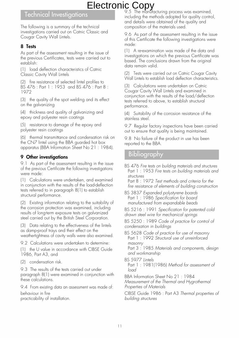
Technical Investigations
The following is a summary of the technicalinvestigations carried out on Catnic Classic andCougar Cavity Wall Lintels.
8 TestsAs part of the assessment resulting in the issue ofthe previous Certificates, tests were carried out toestablish:(1) load deflection characteristics of CatnicClassic Cavity Wall Lintels
(2) fire resistance of selected lintel profiles toBS 476 : Part 1 : 1953 and BS 476 : Part 8 :1972
(3) the quality of the spot welding and its effecton the galvanizing
(4) thickness and quality of galvanizing andepoxy and polyester resin coatings
(5) resistance to damage of the epoxy andpolyester resin coatings
(6) thermal transmittance and condensation risk onthe CN7 lintel using the BBA guarded hot boxapparatus (BBA Information Sheet No 21 : 1984).
9 Other investigations9.1 As part of the assessment resulting in the issueof the previous Certificate the following investigationswere made:(1) Calculations were undertaken, and examinedin conjunction with the results of the load-deflectiontests referred to in paragraph 8(1) to establishstructural performance.
(2) Existing information relating to the suitability ofthe corrosion protection was examined, includingresults of long-term exposure tests on galvanizedsteel carried out by the British Steel Corporation.
(3) Data relating to the effectiveness of the lintelsas damp-proof trays and their effect on theweathertightness of cavity walls were also examined.
9.2 Calculations were undertaken to determine:(1) the U value in accordance with CIBSE Guide1986, Part A3, and
(2) condensation risk.
9.3 The results of the tests carried out underparagraph 8(1) were examined in conjunction withthese calculations.
9.4 From existing data an assessment was made of:behaviour in firepracticability of installation.
9.5 The manufacturing process was examined,including the methods adopted for quality control,and details were obtained of the quality andcomposition of the materials used.
9.6 As part of the assessment resulting in the issueof this Certificate the following investigations weremade:(1) A re-examination was made of the data andinvestigations on which the previous Certificate wasbased. The conclusions drawn from the originaldata remain valid.
(2) Tests were carried out on Catnic Cougar CavityWall Lintels to establish load deflection characteristics.
(3) Calculations were undertaken on CatnicCougar Cavity Wall Lintels and examined inconjunction with the results of the load/deflectiontests referred to above, to establish structuralperformance.
(4) Suitability of the corrosion resistance of thestainless steel.
9.7 Regular factory inspections have been carriedout to ensure that quality is being maintained.
9.8 No failure of the product in use has beenreported to the BBA.
Bibliography
BS 476 Fire tests on building materials and structuresPart 1 : 1953 Fire tests on building materials andstructuresPart 8 : 1972 Test methods and criteria for thefire resistance of elements of building construction
BS 3837 Expanded polystyrene boardsPart 1 : 1986 Specification for boardmanufactured from expandable beads
BS 5216 : 1991 Specification for patented colddrawn steel wire for mechanical springsBS 5250 : 1989 Code of practice for control ofcondensation in buildingsBS 5628 Code of practice for use of masonry
Part 1 : 1992 Structural use of unreinforcedmasonryPart 3 : 1985 Materials and components, designand workmanship
BS 5977 LintelsPart 1 : 1981(1986) Method for assessment ofload
BBA Information Sheet No 21 : 1984Measurement of the Thermal and HygrothermalProperties of MaterialsCIBSE Guide 1986 : Part A3 Thermal properties ofbuilding structures
11
Electronic Copy
©1997
British Board of AgrémentP O Box No 195, Bucknalls LaneGarston, Watford, Herts WD2 7NGFax: 01923 662133
For technical or additionalinformation, tel: 01923 670844.For information about AgrémentCertificate validity and scope, tel:Hotline: 01923 662900
On behalf of the British Board of Agrément
Date of Second issue: 6th February 1997 Director
*Original Detail Sheet issued 28th March 1991. This amended version includes references to the revised BuildingRegulations and associated text, and the addition of the Cougar range.
Electronic Copy
Readers are advised to check the validity of this Detail Sheet by either referring to the Index of Current BBA Publications or contactingthe BBA direct (Telephone Hotline 01923 662900).
Technical Specification
1 Description1.1 Catnic External Solid Wall Lintels areavailable in the profiles shown in Table 1. Thelintels incorporate perforations on the appropriatefaces to provide a key for plastering.
1.2 Spring clips manufactured from 2.0 mmdiameter galvanized steel wire to BS 5216 :1991 are available for fixing timber insertsrequired to support curtain tracks.
1.3 Types CN71 and CN81 incorporatepolystyrene insulation.
Design Data
2 GeneralCatnic External Solid Wall Lintels are satisfactoryfor use in external walls of brickwork and/orblockwork to provide support to wall, roof or floorloads (or a combination of these), above windowor door openings.
3 Structural performance3.1 Types CN5, CN6, CN46, CN52,CN56, CN66, CN71 and CN81 haveadequate strength and stiffness to sustain
the uniformly distributed working loads given inTable 1, subject to the following conditions:(1) The defined sizes of masonry unit and clearspans are not exceeded.
(2) With types CN71 and CN81 not more thanhalf the total load on the lintel is supported at theouter leaf position.(3) The specified loads in Table 1 relate to simply-supported lintels laterally and torsionally unrestrained.Therefore there are no requirements for compositeaction with, or restraint by, adjacent elements ofconstruction.(4) Where part of the loading is applied asconcentrated loads, each load must be supportedover a length of lintel of not less than 200 mm. Insuch cases the total applied loading must notproduce bending moments, shear forces orreactions greater than those produced by theuniformly distributed loads specified in Table 1.
3.2 In addition to the requirements specificallyreferred to in this Detail Sheet, structures of brickworkor blockwork in which the lintels are incorporatedmust be designed and constructed to comply withthe following technical specifications as appropriate:(1) BS 5628 : Part 1 : 1992 and BS 5628 :Part 3 : 1985.(2) Section 1, Part C of Approved Document A1/2to the Building Regulations 1991 (as amended1994) (England and Wales).(3) Small Building Guide for compliance withPart C of the Building Standards (Scotland)Regulations 1990 (as amended).(4) Section 3 of DoE (NI) Technical Booklet D :1994 Structure.
3.3 Guidance for the assessment of loads on lintelsin masonry is given in BS 5977 : Part 1 :1981(1986).
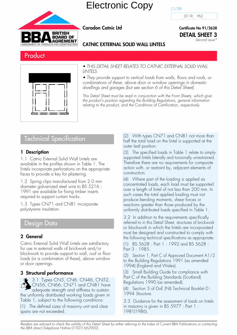
• THIS DETAIL SHEET RELATES TO CATNIC EXTERNAL SOLID WALLLINTELS.• They provide support to vertical loads from walls, floors and roofs, orcombinations of these, above door or window openings in domesticdwellings and garages (but see section 6 of this Detail Sheet).
This Detail Sheet must be read in conjunction with the Front Sheets, which givethe product’s position regarding the Building Regulations, general informationrelating to the product, and the Conditions of Certification, respectively.
Certificate No 91/2638
DETAIL SHEET 3Second issue*
Caradon Catnic Ltd
CATNIC EXTERNAL SOLID WALL LINTELS
Product
CI/SfB
(31.9) Hh2
Electronic Copy
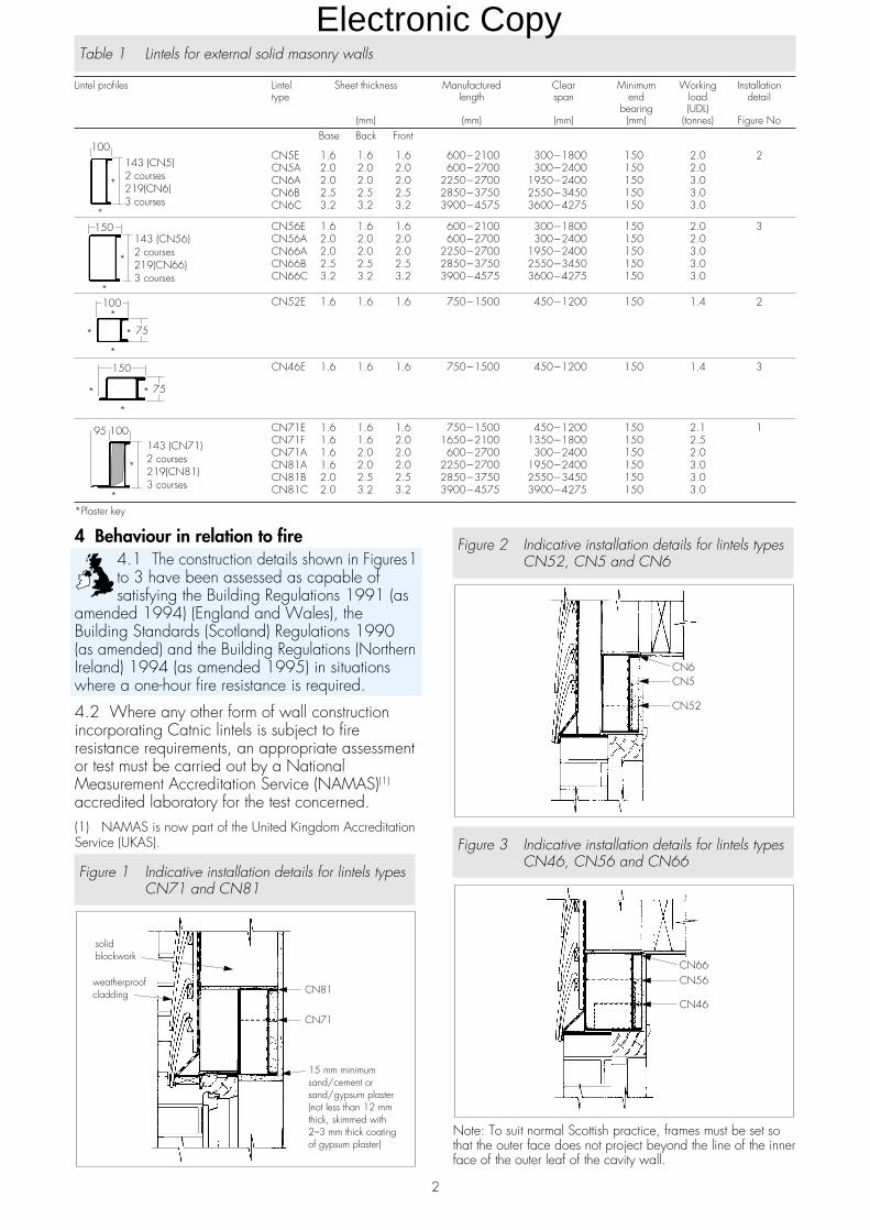
Table 1 Lintels for external solid masonry walls
Lintel profiles Lintel Sheet thickness Manufactured Clear Minimum Working Installationtype length span end load detail
bearing (UDL)(mm) (mm) (mm) (mm) (tonnes) Figure No
Base Back Front
CN5E 1.6 1.6 1.6 600�2100 300�1800 150 2.0 2CN5A 2.0 2.0 2.0 600�2700 300�2400 150 2.0CN6A 2.0 2.0 2.0 2250�2700 1950�2400 150 3.0CN6B 2.5 2.5 2.5 2850�3750 2550�3450 150 3.0CN6C 3.2 3.2 3.2 3900�4575 3600�4275 150 3.0
CN56E 1.6 1.6 1.6 600�2100 300�1800 150 2.0 3CN56A 2.0 2.0 2.0 600�2700 300�2400 150 2.0CN66A 2.0 2.0 2.0 2250�2700 1950�2400 150 3.0CN66B 2.5 2.5 2.5 2850�3750 2550�3450 150 3.0CN66C 3.2 3.2 3.2 3900�4575 3600�4275 150 3.0
CN52E 1.6 1.6 1.6 750�1500 450�1200 150 1.4 2
CN46E 1.6 1.6 1.6 750�1500 450�1200 150 1.4 3
CN71E 1.6 1.6 1.6 750�1500 450�1200 150 2.1 1CN71F 1.6 1.6 2.0 1650�2100 1350�1800 150 2.5CN71A 1.6 2.0 2.0 600�2700 300�2400 150 2.0CN81A 1.6 2.0 2.0 2250�2700 1950�2400 150 3.0CN81B 2.0 2.5 2.5 2850�3750 2550�3450 150 3.0CN81C 2.0 3.2 3.2 3900�4575 3900�4275 150 3.0
*Plaster key
2
4 Behaviour in relation to fire4.1 The construction details shown in Figures1to 3 have been assessed as capable ofsatisfying the Building Regulations 1991 (as
amended 1994) (England and Wales), theBuilding Standards (Scotland) Regulations 1990(as amended) and the Building Regulations (NorthernIreland) 1994 (as amended 1995) in situationswhere a one-hour fire resistance is required.
4.2 Where any other form of wall constructionincorporating Catnic lintels is subject to fireresistance requirements, an appropriate assessmentor test must be carried out by a NationalMeasurement Accreditation Service (NAMAS)(1)
accredited laboratory for the test concerned.(1) NAMAS is now part of the United Kingdom AccreditationService (UKAS).
Figure 1 Indicative installation details for lintels typesCN71 and CN81
Figure 2 Indicative installation details for lintels typesCN52, CN5 and CN6
Figure 3 Indicative installation details for lintels typesCN46, CN56 and CN66
Note: To suit normal Scottish practice, frames must be set sothat the outer face does not project beyond the line of the innerface of the outer leaf of the cavity wall.
Electronic Copy
5 Thermal transmittanceEvaluated constructions
5.1 The typical construction detailscontaining lintels types CN71, CN81,CN5, CN6, CN46, CN52, CN56 and
CN66 (see Figures 1 to 3) were modellednumerically to determine their likely hygrothermalperformance. The analysis of the details examinedshowed that the additional thermal energy passingthrough the lintel assemblies is sufficiently small inthe context of domestic dwellings for it to bediscounted in assessing the overall building energyconsumption, and in general may be included withthe wall heat transmission term. Other details usingthe lintels where the U value of the solid wall issimilar to that of the detail assessed should have asimilar performance.
5.2 The basic U values of all the solid walls in thedetails assessed is such that they should only beused where one of the calculation procedures[Target U-value method/Calculated trade-offs(method 2)/Calculated trade-off approach orEnergy Rating method/Energy targets (method 3)/Energy target approach or Calculation method orEnergy Use method] is being used to showcompliance to the thermal requirements or wherethe Elemental method/approach is being used andthere is no requirement (ie external walls ofgarages and other unheated spaces). Similardetails but with the tile hanging could also be usedin semi-exposed walls, provided the basic U valueof the wall is less than 0.6 Wm�2K�1, when usingthe Elemental method/approach.
5.3 In Part J of the Technical Standards ofthe Building Standards (Scotland) Regulations1990 (as amended) and Part F of the Building
Regulations (Northern Ireland) 1994 (as amended1995) a requirement is set out to limit the severityof thermal bridging permitted in lintel and similarassemblies. The analysis showed that for the detailsexamined the resultant surface temperatures arewithin the effective practical limits implied by thestipulated maximum U value requirement of1.2 Wm�2K�1 given in the Regulations(1).(1) Standard J2 in Scotland and Technical booklet F inNorthern Ireland.
Other constructions5.4 Where other forms of construction are to beused and compliance with the thermal requirementshas to be shown, an assessment or an appropriatetest must be carried out on the actual detail proposed.
6 Condensation riskEvaluated constructions
6.1 The typical construction detailscontaining lintels types CN71, CN81,CN5, CN6, CN46, CN52, CN56 and
CN66 (see Figures 1 to 3) were modellednumerically to determine their likely hygrothermal
performance. The numerical analysis gave the likelydifference in temperature between the lintel soffitarea and the remainder of the wall.
6.2 The analysis showed that, for the detailsdescribed in Figure 1, in normal domesticcircumstances the extent and severity of anyresulting interstitial or surface condensation will beinsufficient to cause any significant problem.Where the details are likely to be exposed torelative humidities of more than 70% at 20°C forconsiderable periods of time, special precautionswill be needed to prevent condensation accumulatingaround the details in the region of the soffit.
6.3 The analysis showed that, for the detailsdescribed in Figures 2 and 3, condensation willoccur and moisture may accumulate on andaround the lintel area under conditions of highinternal humidity. This type of construction thereforewould be acceptable for domestic garages andsimilar situations, but not for dwellings, residentialbuildings or for parts of other buildings where highinternal humidities are predicted.
Other constructions6.4 Where Catnic lintels are used in detailsnot described in this Detail Sheet, anassessment or appropriate test to determine
the extent of any likely condensation accumulationshould be carried out in accordance with theprinciples described in BS 5250 : 1989.
6.5 Consideration should be given to the possibleneed to isolate the window head from condensationfrom the lintel or to use preservative treated timber forthe head member (see section 8 of the Front Sheets).
Installation
7 General7.1 Typical installation details are shown inFigures 1 to 3. The lintels must be installed with atleast the minimum end bearing dimensions given inTable 1 and be fully bedded on bricklaying mortar.
7.2 Operations likely to damage the protectivecoatings or impair the strength of the lintels (forexample, cutting, welding or drilling) must not beundertaken.
7.3 A 19 mm by 38 mm softwood insert may befixed to the back of the lintels with the spring clipssupplied, at 400 mm centres, to provide a fixingfor curtain tracks.
Technical Investigations
The following is a summary of the technicalinvestigations carried out on Catnic External SolidWall Lintels types CN5, CN6, CN46, CN52,CN56, CN66, CN71, CN81.
3
Electronic Copy
8 TestsAs part of the assessment resulting in the issue of theprevious Certificates, tests were carried out toestablish:(1) load deflection characteristics(2) fire resistance of selected lintel profiles toBS 476 : Part 1 : 1953 and BS 476 : Part 8 : 1972(3) the quality of the spot welding and its effect onthe galvanizing(4) thickness and quality of galvanizing andepoxy and polyester resin coatings(5) resistance to damage of the epoxy andpolyester resin coatings.
9 Other investigations9.1 As part of the assessment resulting in the issueof the previous Certificates the followinginvestigations were made:(1) Calculations were undertaken, and examinedin conjunction with the results of the load-deflectiontests referred to in section 8.1(1), to establishstructural performance.(2) Existing information relating to the suitability ofthe corrosion protection was examined, includingresults of long-term exposure tests on galvanizedsteel carried out by the British Steel Corporation.(3) Calculations were undertaken to determine:the U value in accordance with CIBSE Guide
1986, Part A3 and condensation risk.(4) Existing data were used to make anassessment of:behaviour in firepracticability of installation.
(5) The manufacturing process was examined,including the methods adopted for quality control,and details were obtained of the quality andcomposition of the materials used.9.2 As part of the assessment resulting in the issue ofthis Certificate the following investigations were made:
(1) A re-examination was made of the data andinvestigations on which the previous Certificate wasbased. The conclusions drawn from the originaldata remain valid.(2) Tests were carried out on lintels types CN5E,CN46, CN52, CN56E, CN71E and CN71F toestablish load deflection characteristics.(3) Calculations were undertaken on lintels typesCN5E, CN46, CN52, CN56E, CN71E andCN71F and examined in conjunction with theresults of the load/deflection tests referred toabove, in order to establish structural performance.(4) Suitability of the corrosion resistance of thestainless steel.
9.3 Regular factory inspections have been carriedout to ensure that quality is being maintained.
9.4 No failure of the product in use has beenreported to the BBA.
Bibliography
BS 476 Fire tests on building materials and structuresPart 1 : 1953 Fire tests on building materials andstructuresPart 8 : 1972 Test methods and criteria for thefire resistance of elements of building construction
BS 5216 : 1991 Specification for patented colddrawn steel wire for mechanical springsBS 5250 : 1989 Code of practice for control ofcondensation in buildingsBS 5628 Code of practice for use of masonry
Part 1 : 1992 Structural use of unreinforced masonryPart 3 : 1985 Materials and components, designand workmanship
BS 5977 LintelsPart 1 : 1981(1986) Method for assessment ofload
CIBSE Guide 1986 : Part A3 Thermal properties ofbuilding structures
On behalf of the British Board of Agrément
Date of Second issue: 6th February 1997 Director
*Original Detail Sheet issued 28th March 1991. This amended version includes references to the revised BuildingRegulations and associated text.
©1997
British Board of AgrémentP O Box No 195, Bucknalls LaneGarston, Watford, Herts WD2 7NGFax: 01923 662133
For technical or additionalinformation, tel: 01923 670844.For information about AgrémentCertificate validity and scope, tel:Hotline: 01923 662900
Electronic Copy
Readers are advised to check the validity of this Detail Sheet by either referring to the Index of Current BBA Publications or contactingthe BBA direct (Telephone Hotline 01923 662900).
Technical Specification
1 Description1.1 Catnic Timber Frame Lintels are available inthe profiles shown in Table 1.
1.2 Lintels are supplied with retaining clips (seesection 3.2).
Design Data
2 GeneralCatnic Timber Frame Lintels are satisfactory for usein timber frame construction to support facingbrickwork over window or door openings.
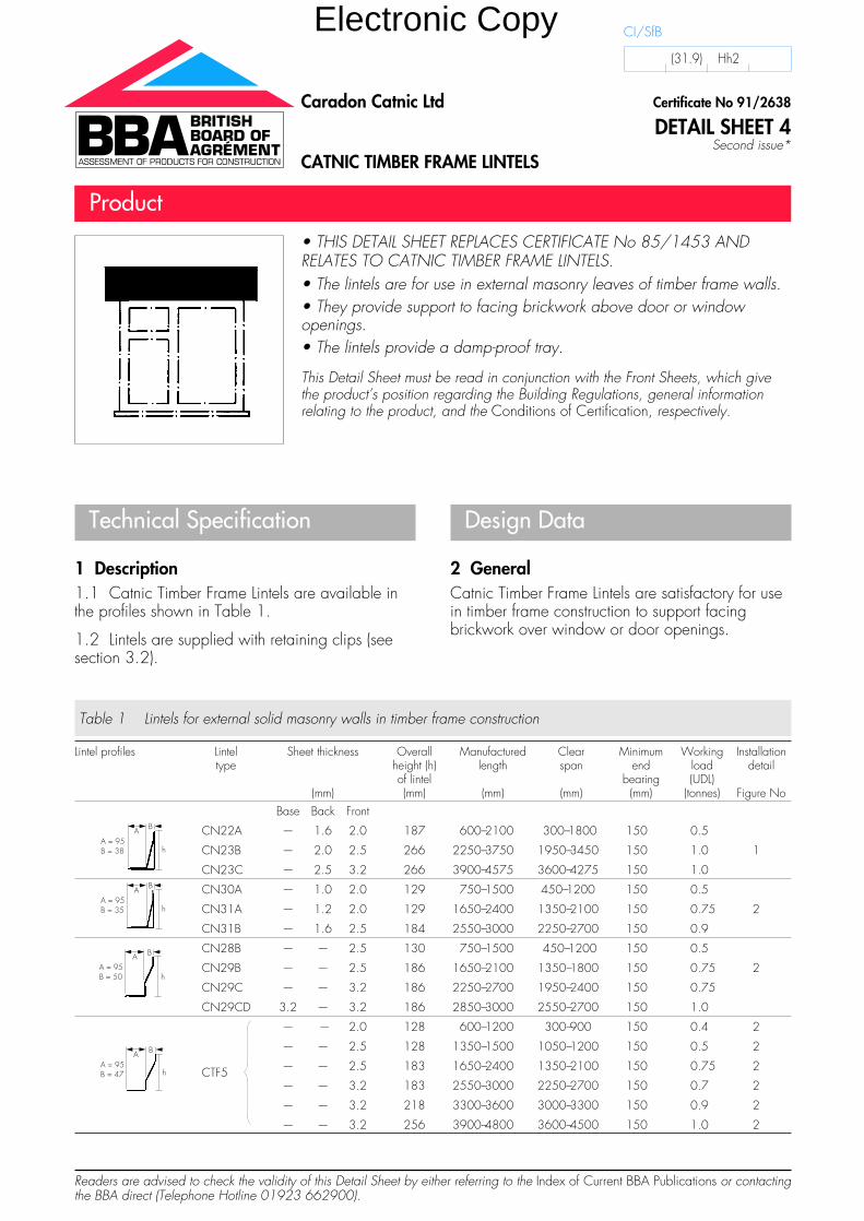
• THIS DETAIL SHEET REPLACES CERTIFICATE No 85/1453 ANDRELATES TO CATNIC TIMBER FRAME LINTELS.• The lintels are for use in external masonry leaves of timber frame walls.• They provide support to facing brickwork above door or windowopenings.• The lintels provide a damp-proof tray.
This Detail Sheet must be read in conjunction with the Front Sheets, which givethe product’s position regarding the Building Regulations, general informationrelating to the product, and the Conditions of Certification, respectively.
Certificate No 91/2638
DETAIL SHEET 4Second issue*
Caradon Catnic Ltd
CATNIC TIMBER FRAME LINTELS
Product
CI/SfB
(31.9) Hh2
Table 1 Lintels for external solid masonry walls in timber frame construction
Lintel profiles Lintel Sheet thickness Overall Manufactured Clear Minimum Working Installationtype height (h) length span end load detail
of lintel bearing (UDL)(mm) (mm) (mm) (mm) (mm) (tonnes) Figure No
Base Back Front
CN22A — 1.6 2.0 187 600–2100 300–1800 150 0.5
CN23B — 2.0 2.5 266 2250–3750 1950–3450 150 1.0 1
CN23C — 2.5 3.2 266 3900–4575 3600–4275 150 1.0
CN30A — 1.0 2.0 129 750–1500 450–1200 150 0.5
CN31A — 1.2 2.0 129 1650–2400 1350–2100 150 0.75 2
CN31B — 1.6 2.5 184 2550–3000 2250–2700 150 0.9
CN28B — — 2.5 130 750–1500 450–1200 150 0.5
CN29B — — 2.5 186 1650–2100 1350–1800 150 0.75 2
CN29C — — 3.2 186 2250–2700 1950–2400 150 0.75
CN29CD 3.2 — 3.2 186 2850–3000 2550–2700 150 1.0
— — 2.0 128 600–1200 300–900 150 0.4 2
— — 2.5 128 1350–1500 1050–1200 150 0.5 2
CTF5 — — 2.5 183 1650–2400 1350–2100 150 0.75 2
— — 3.2 183 2550–3000 2250–2700 150 0.7 2
— — 3.2 218 3300–3600 3000–3300 150 0.9 2
— — 3.2 256 3900–4800 3600–4500 150 1.0 2
Electronic Copy
3 Structural performance
3.1 The lintels have adequate strength andstiffness to sustain the uniformly distributedworking loads given in Table 1, provided
the defined cavity widths, size of masonry unit andclear spans are not exceeded.
3.2 The retaining clips are used to restrain rotationof the lintel. The clip design allows for relativevertical movement between the timber inner leafand the facing brickwork.
3.3 During design, the load transfer from the outerleaf must be taken into account.
3.4 In addition to the requirements specificallyreferred to in this Detail Sheet, structures of brickworkor blockwork in which the lintels are incorporatedmust be designed and constructed to comply withthe following technical specifications as appropriate:
(1) BS 5628 : Part 1 : 1992 and BS 5628 :Part 3 : 1985.
(2) Section 1, Part C of Approved Document A1/2to the Building Regulations 1991 (as amended1994) (England and Wales).
(3) Small Building Guide for compliance withPart C of the Building Standards (Scotland)Regulations 1990 (as amended).
(4) Section 3 of DoE (NI) Technical Booklet D :1994 Structure.
3.5 The structural timber framework must bedesigned and constructed in accordance withBS 5268 : Part 2 : 1995.
3.6 Guidance for the assessment of loads on lintelsin masonry is given in BS 5977 : Part 1 :1981(1986).
4 Behaviour in relation to fire
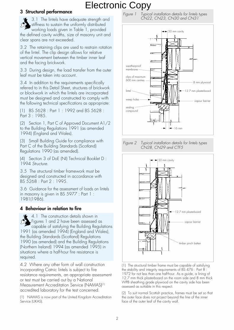
4.1 The construction details shown inFigures 1 and 2 have been assessed ascapable of satisfying the Building Regulations
1991 (as amended 1994) (England and Wales),the Building Standards (Scotland) Regulations1990 (as amended) and the Building Regulations(Northern Ireland) 1994 (as amended 1995) insituations where a half-hour fire resistance isrequired.
4.2 Where any other form of wall constructionincorporating Catnic lintels is subject to fireresistance requirements, an appropriate assessmentor test must be carried out by a NationalMeasurement Accreditation Service (NAMAS)(1)
accredited laboratory for the test concerned.(1) NAMAS is now part of the United Kingdom AccreditationService (UKAS).
Figure 1 Typical installation details for lintels typesCN22, CN23, CN30 and CN31
Figure 2 Typical installation details for lintels typesCN28, CN29 and CTF5
(1) The structural timber frame must be capable of satisfyingthe stability and integrity requirements of BS 476 : Part 8 :1972 for not less than one half-hour. As a guide, a lining of12.7 mm thick plasterboard on the room side and 8 mm thickWPB sheathing grade plywood on the cavity side has beenassessed as suitable in this respect.
(2) To suit normal Scottish practice, frames must be set so thatthe outer face does not project beyond the line of the innerface of the outer leaf of the cavity wall.
50 mm cavity
12.7 mm plasterboard
vapour barrier
timber pinch batten
50 mm cavity
8 mm plywood
12.7 mm plasterboard
vapour barrier
weatherproofmembrane
clips of maximum600 mm centres
weep holes
lintel
sealingcompound
16 mm
2
Electronic Copy
5 Thermal transmittanceEvaluated constructions
5.1 The typical construction details asoutlined in Figures 1 and 2 were modellednumerically to determine their likely
hygrothermal performance. Similar details shouldhave a similar performance.
5.2 The analysis of the detail examinedshowed that the additional heat loss due tothermal bridging will be similar to that to be
expected from the lintel details given in Diagrams 3and 7 of Approved Document L of the BuildingRegulations 1991 (as amended 1994) (Englandand Wales), and therefore can be ignored.
5.3 In the context of domestic dwellings, theadditional thermal energy passing through the lintelassembly is sufficiently small for it to be discountedwhen assessing the overall energy consumption ofthe building and, in general, may be with the termfor wall heat transmission. The timber inner lintelshould be treated in the same manner as the timberstudding when determining the standard U value ofthe wall [see Appendix B of Approved Document Lof the Building Regulations 1991 (as amended1994) (England and Wales)].
5.4 The U value of the example detailsgiven in Figures 1 and 2 is less than thestipulated maximum U value requirement of
1.2 Wm�2K�1 given in Standard J2 of the BuildingStandards (Scotland) Regulations 1990 (asamended) and Technical Booklet F of the BuildingRegulations (Northern Ireland) 1994 (as amended1995).
6 Condensation riskEvaluated constructions
6.1 The typical construction details asoutlined in Figures 1 and 2 were modellednumerically to determine their likely
hygrothermal performance. Similar details shouldhave similar performances.
6.2 The minimum surface temperatures predictedby the analysis were similar to those which could beexpected from lintel details given in diagrams 3and 7 of Approved Document L and the risk of surfacecondensation will, therefore, be similar. The analysisalso showed that if the door/window frame belowthe lintel is moved further out than shown, theminimum surface temperature will be lower and theassociated risk of surface condensation higher thanthe details in Approved Document L.
6.3 The analysis also showed that in commonwith other timber frame lintel assemblies, unless afully effective vapour barrier (eg 500 gaugepolythene) is provided around the assembly,moisture may accumulate on and around the lintel
and associated timber. It is essential, therefore, thatparticular attention is paid to ensuring that thevapour barrier is continuous at the lintel position (ieit continues round into the soffit and reveals and issuitably sealed at the corners).
6.4 In normal domestic circumstances the extentand severity of any resulting interstitial or surfacecondensation is judged to be insufficient to causeany significant problem. Where the details arelikely to be exposed to relative humidity of morethan 75% at 20°C for considerable periods oftime, special precautions will be needed to preventcondensation accumulating around the details inthe region of the soffit.
6.5 Other details are possible and the actualconstruction proposed should be assessed or anappropriate test carried out in accordance with theprinciples described in BS 5250 : 1989.
6.6 Consideration should be given to the possibleneed either to isolate the window head fromcondensation from the lintel or to use preservativetreated timber for the head member (see section 7of this Detail Sheet).
Installation
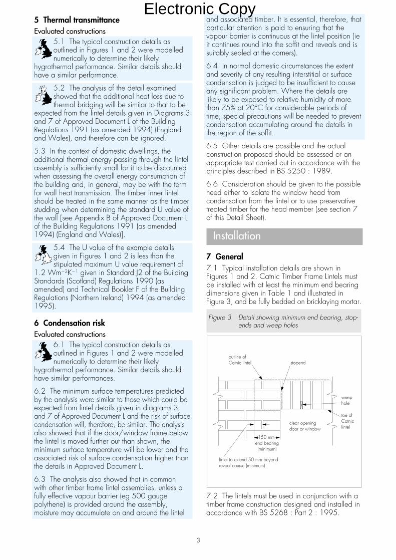
7 General7.1 Typical installation details are shown inFigures 1 and 2. Catnic Timber Frame Lintels mustbe installed with at least the minimum end bearingdimensions given in Table 1 and illustrated inFigure 3, and be fully bedded on bricklaying mortar.
Figure 3 Detail showing minimum end bearing, stop-ends and weep holes
7.2 The lintels must be used in conjunction with atimber frame construction designed and installed inaccordance with BS 5268 : Part 2 : 1995.
stopendoutline ofCatnic lintel
weephole
toe ofCatniclintel
clear openingdoor or window
150 mmend bearing(minimum)
lintel to extend 50 mm beyondreveal course (minimum)
3
Electronic Copy
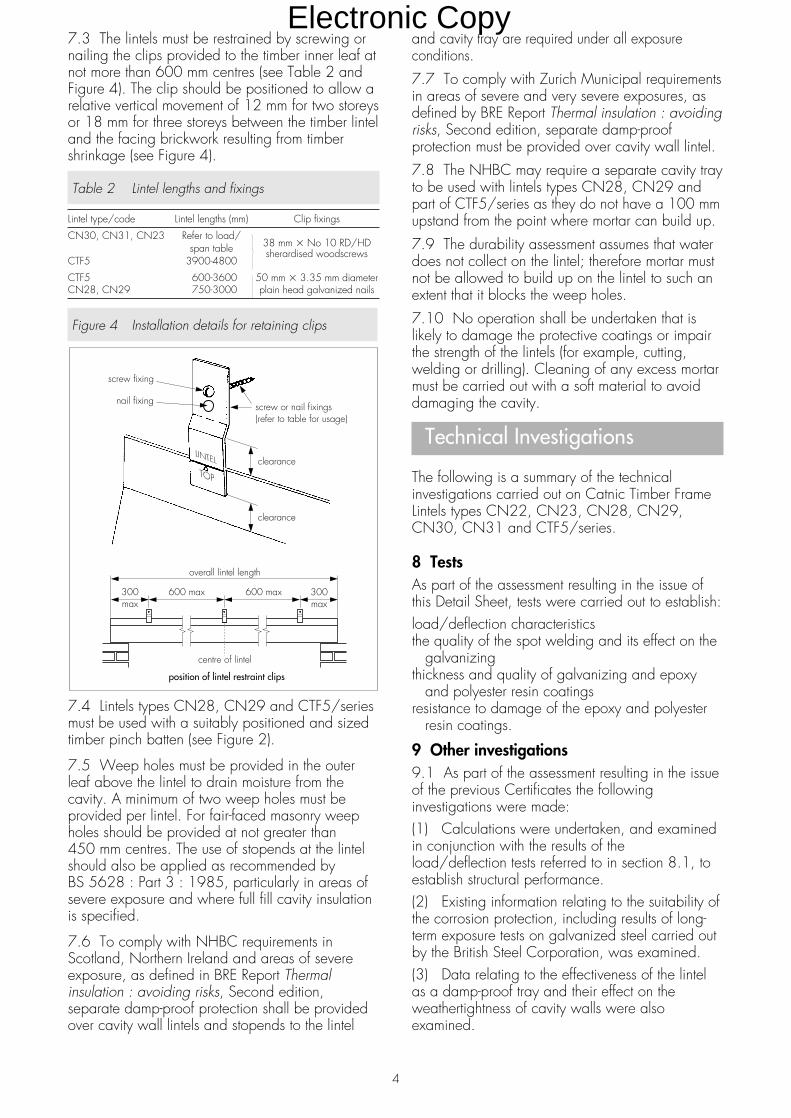
7.3 The lintels must be restrained by screwing ornailing the clips provided to the timber inner leaf atnot more than 600 mm centres (see Table 2 andFigure 4). The clip should be positioned to allow arelative vertical movement of 12 mm for two storeysor 18 mm for three storeys between the timber linteland the facing brickwork resulting from timbershrinkage (see Figure 4).
Table 2 Lintel lengths and fixings
Lintel type/code Lintel lengths (mm) Clip fixings
CN30, CN31, CN23 Refer to load/38 mm � No 10 RD/HDspan table
CTF5 3900-4800sherardised woodscrews
CTF5 600-3600 50 mm � 3.35 mm diameterCN28, CN29 750-3000 plain head galvanized nails
Figure 4 Installation details for retaining clips
7.4 Lintels types CN28, CN29 and CTF5/seriesmust be used with a suitably positioned and sizedtimber pinch batten (see Figure 2).
7.5 Weep holes must be provided in the outerleaf above the lintel to drain moisture from thecavity. A minimum of two weep holes must beprovided per lintel. For fair-faced masonry weepholes should be provided at not greater than450 mm centres. The use of stopends at the lintelshould also be applied as recommended byBS 5628 : Part 3 : 1985, particularly in areas ofsevere exposure and where full fill cavity insulationis specified.
7.6 To comply with NHBC requirements inScotland, Northern Ireland and areas of severeexposure, as defined in BRE Report Thermalinsulation : avoiding risks, Second edition,separate damp-proof protection shall be providedover cavity wall lintels and stopends to the lintel
and cavity tray are required under all exposureconditions.
7.7 To comply with Zurich Municipal requirementsin areas of severe and very severe exposures, asdefined by BRE Report Thermal insulation : avoidingrisks, Second edition, separate damp-proofprotection must be provided over cavity wall lintel.
7.8 The NHBC may require a separate cavity trayto be used with lintels types CN28, CN29 andpart of CTF5/series as they do not have a 100 mmupstand from the point where mortar can build up.
7.9 The durability assessment assumes that waterdoes not collect on the lintel; therefore mortar mustnot be allowed to build up on the lintel to such anextent that it blocks the weep holes.
7.10 No operation shall be undertaken that islikely to damage the protective coatings or impairthe strength of the lintels (for example, cutting,welding or drilling). Cleaning of any excess mortarmust be carried out with a soft material to avoiddamaging the cavity.
Technical Investigations
The following is a summary of the technicalinvestigations carried out on Catnic Timber FrameLintels types CN22, CN23, CN28, CN29,CN30, CN31 and CTF5/series.
8 TestsAs part of the assessment resulting in the issue ofthis Detail Sheet, tests were carried out to establish:load/deflection characteristicsthe quality of the spot welding and its effect on the
galvanizingthickness and quality of galvanizing and epoxy
and polyester resin coatingsresistance to damage of the epoxy and polyester
resin coatings.
9 Other investigations9.1 As part of the assessment resulting in the issueof the previous Certificates the followinginvestigations were made:(1) Calculations were undertaken, and examinedin conjunction with the results of theload/deflection tests referred to in section 8.1, toestablish structural performance.(2) Existing information relating to the suitability ofthe corrosion protection, including results of long-term exposure tests on galvanized steel carried outby the British Steel Corporation, was examined.(3) Data relating to the effectiveness of the lintelas a damp-proof tray and their effect on theweathertightness of cavity walls were alsoexamined.
4
Electronic Copy
(4) Calculations were undertaken to determine:the U value in accordance with CIBSE Guide
1986, Part A, andcondensation risk.
(5) Existing data were used to make anassessment of:behaviour in firepracticability of installation.
(6) The manufacturing process was examined,including the methods adopted for quality control,and details were obtained of the quality andcomposition of the materials used.
9.2 As part of the assessment resulting in the issueof this Certificate a re-examination was made ofthe data and investigations on which the previousCertificate was based. The conclusions drawn fromthe original data remain valid.
9.3 Regular factory inspections have been carriedout to ensure that quality is being maintained.
9.4 No failure of the product in use has beenreported to the BBA.
Bibliography
BS 5250 : 1989 Code of practice for control ofcondensation in buildings
BS 5628 Code of practice for use of masonryPart 1 : 1992 Structural use of unreinforcedmasonryPart 3 : 1985 Materials and components, designand workmanship
BS 5977 LintelsPart 1 : 1981(1986) Method for assessment ofload
BBA Information Sheet No 21 : 1984Measurement of the Thermal and HygrothermalProperties of Materials
CIBSE Guide 1986 : Part A3 Thermal properties ofbuilding structures
5
On behalf of the British Board of Agrément
Date of Second issue: 6th February 1997 Director
*Original Detail Sheet issued 28th March 1991. This amended version includes references to the revised BuildingRegulations and associated text.
Electronic Copy
©1997
British Board of AgrémentP O Box No 195, Bucknalls LaneGarston, Watford, Herts WD2 7NGFax: 01923 662133
For technical or additionalinformation, tel: 01923 670844.For information about AgrémentCertificate validity and scope, tel:Hotline: 01923 662900
Electronic Copy

7
Electronic Copy
Readers are advised to check the validity of this Detail Sheet by either referring to the Index of Current BBA Publications or contactingthe BBA direct (Telephone Hotline 01923 662900).
Technical Specification
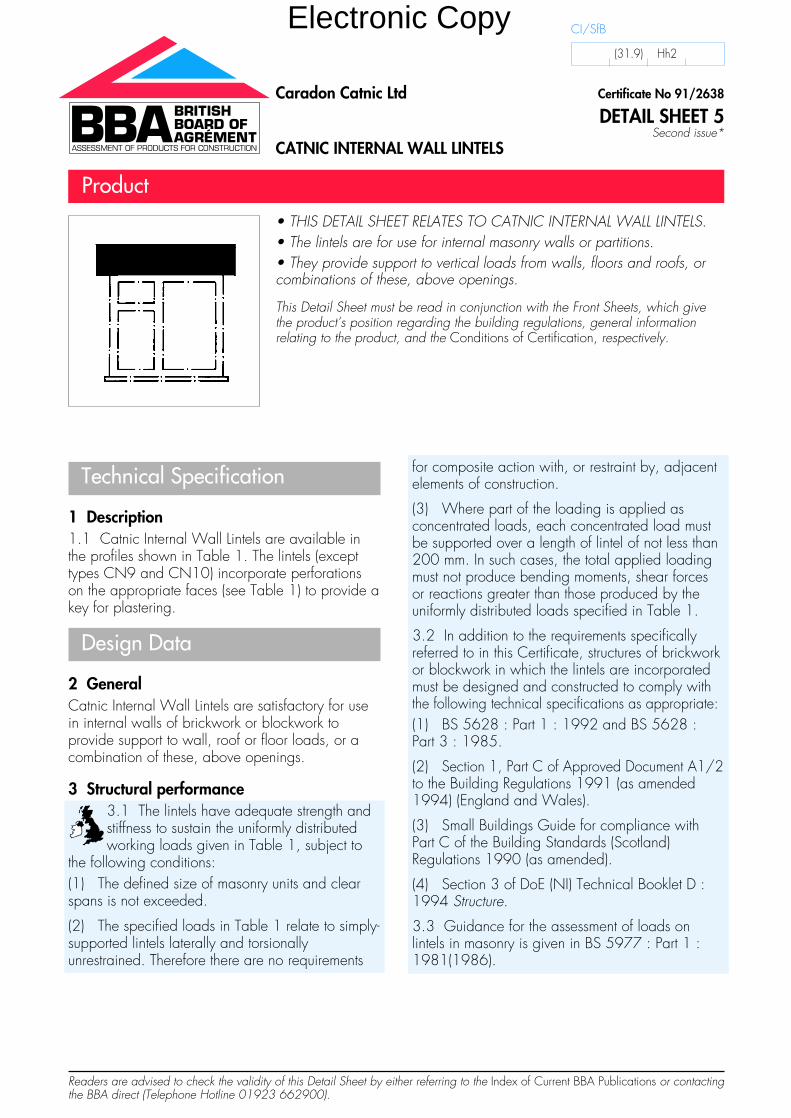
1 Description1.1 Catnic Internal Wall Lintels are available inthe profiles shown in Table 1. The lintels (excepttypes CN9 and CN10) incorporate perforationson the appropriate faces (see Table 1) to provide akey for plastering.
Design Data
2 GeneralCatnic Internal Wall Lintels are satisfactory for usein internal walls of brickwork or blockwork toprovide support to wall, roof or floor loads, or acombination of these, above openings.
3 Structural performance3.1 The lintels have adequate strength andstiffness to sustain the uniformly distributedworking loads given in Table 1, subject to
the following conditions:(1) The defined size of masonry units and clearspans is not exceeded.
(2) The specified loads in Table 1 relate to simply-supported lintels laterally and torsionallyunrestrained. Therefore there are no requirements
for composite action with, or restraint by, adjacentelements of construction.
(3) Where part of the loading is applied asconcentrated loads, each concentrated load mustbe supported over a length of lintel of not less than200 mm. In such cases, the total applied loadingmust not produce bending moments, shear forcesor reactions greater than those produced by theuniformly distributed loads specified in Table 1.
3.2 In addition to the requirements specificallyreferred to in this Certificate, structures of brickworkor blockwork in which the lintels are incorporatedmust be designed and constructed to comply withthe following technical specifications as appropriate:(1) BS 5628 : Part 1 : 1992 and BS 5628 :Part 3 : 1985.
(2) Section 1, Part C of Approved Document A1/2to the Building Regulations 1991 (as amended1994) (England and Wales).
(3) Small Buildings Guide for compliance withPart C of the Building Standards (Scotland)Regulations 1990 (as amended).
(4) Section 3 of DoE (NI) Technical Booklet D :1994 Structure.
3.3 Guidance for the assessment of loads onlintels in masonry is given in BS 5977 : Part 1 :1981(1986).
• THIS DETAIL SHEET RELATES TO CATNIC INTERNAL WALL LINTELS.• The lintels are for use for internal masonry walls or partitions.• They provide support to vertical loads from walls, floors and roofs, orcombinations of these, above openings.
This Detail Sheet must be read in conjunction with the Front Sheets, which givethe product’s position regarding the building regulations, general informationrelating to the product, and the Conditions of Certification, respectively.
Certificate No 91/2638
DETAIL SHEET 5Second issue*
Caradon Catnic Ltd
CATNIC INTERNAL WALL LINTELS
Product
CI/SfB
(31.9) Hh2
Electronic Copy
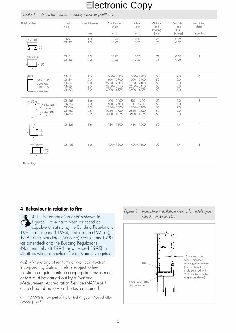
Table 1 Lintels for internal masonry walls or partitions
Lintel profiles Lintel Sheet thickness Manufactured Clear Minimum Working Installationtype length span end load detail
bearing (UDL)(mm) (mm) (mm) (mm) (tonnes) Figure No
CN9 1.0 1050 900 75 0.25 2CN10 1.0 1050 900 75 0.25
CN91 2.0 1050 900 75 0.25 1CN101 2.0 1050 900 75 0.25
CN5E 1.6 600—2100 300—1800 150 2.0 4CN5A 2.0 600—2700 300—2400 150 2.0CN6A 2.0 2250—2700 1950—2400 150 3.0CN6B 2.5 2850—3750 2550—3450 150 3.0CN6C 3.2 3900—4575 3600—4275 150 3.0
CN56E 1.6 600—2100 300—1800 150 2.0 3CN56A 2.0 600—2700 300—2400 150 2.0CN66A 2.0 2250—2700 1950—2400 150 3.0CN66B 2.5 2850—3750 2550—3450 150 3.0CN66C 3.2 3900—4575 3600—4275 150 3.0
CN52E 1.6 750—1500 450—1200 150 1.4 4
CN46E 1.6 750—1500 450—1200 150 1.4 3
*Plaster key
2
4 Behaviour in relation to fire
4.1 The construction details shown inFigures 1 to 4 have been assessed ascapable of satisfying the Building Regulations
1991 (as amended 1994) (England and Wales),the Building Standards (Scotland) Regulations 1990(as amended) and the Building Regulations(Northern Ireland) 1994 (as amended 1995) insituations where a one-hour fire resistance is required.
4.2 Where any other form of wall constructionincorporating Catnic lintels is subject to fireresistance requirements, an appropriate assessmentor test must be carried out by a NationalMeasurement Accreditation Service (NAMAS)(1)
accredited laboratory for the test concerned.
(1) NAMAS is now part of the United Kingdom AccreditationService (UKAS).
Figure 1 Indicative installation details for lintels typesCN91 and CN101
Electronic Copy
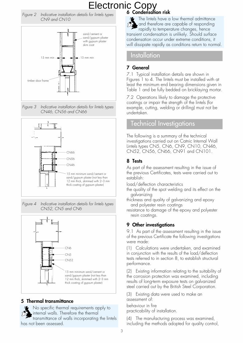
Figure 2 Indicative installation details for lintels typesCN9 and CN10
Figure 3 Indicative installation details for lintels typesCN46, CN56 and CN66
Figure 4 Indicative installation details for lintels typesCN52, CN5 and CN6
5 Thermal transmittanceNo specific thermal requirements apply tointernal walls. Therefore the thermaltransmittance of walls incorporating the lintels
has not been assessed.
6 Condensation riskThe lintels have a low thermal admittanceand therefore are capable of respondingrapidly to temperature changes, hence
transient condensation is unlikely. Should surfacecondensation occur under extreme conditions, itwill dissipate rapidly as conditions return to normal.
Installation
7 General7.1 Typical installation details are shown inFigures 1 to 4. The lintels must be installed with atleast the minimum end bearing dimensions given inTable 1 and be fully bedded on bricklaying mortar.
7.2 Operations likely to damage the protectivecoatings or impair the strength of the lintels (forexample, cutting, welding or drilling) must not beundertaken.
Technical Investigations
The following is a summary of the technicalinvestigations carried out on Catnic Internal WallLintels types CN5, CN6, CN9, CN10, CN46,CN52, CN56, CN66, CN91 and CN101.
8 TestsAs part of the assessment resulting in the issue ofthe previous Certificates, tests were carried out toestablish:load/deflection characteristicsthe quality of the spot welding and its effect on the
galvanizingthickness and quality of galvanizing and epoxy
and polyester resin coatingsresistance to damage of the epoxy and polyester
resin coatings.
9 Other investigations9.1 As part of the assessment resulting in the issueof the previous Certificate the following investigationswere made:(1) Calculations were undertaken, and examinedin conjunction with the results of the load/deflectiontests referred to in section 8, to establish structuralperformance.
(2) Existing information relating to the suitability ofthe corrosion protection was examined, includingresults of long-term exposure tests on galvanizedsteel carried out by the British Steel Corporation.
(3) Existing data were used to make anassessment of:behaviour in firepracticability of installation.
(4) The manufacturing process was examined,including the methods adopted for quality control,
3
Electronic Copy
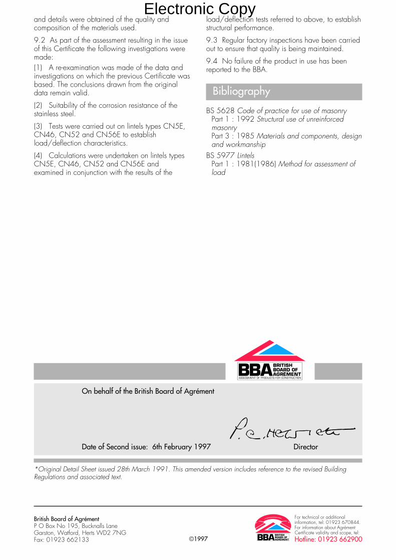
©1997
British Board of AgrémentP O Box No 195, Bucknalls LaneGarston, Watford, Herts WD2 7NGFax: 01923 662133
For technical or additionalinformation, tel: 01923 670844.For information about AgrémentCertificate validity and scope, tel:Hotline: 01923 662900
On behalf of the British Board of Agrément
Date of Second issue: 6th February 1997 Director
*Original Detail Sheet issued 28th March 1991. This amended version includes reference to the revised BuildingRegulations and associated text.
and details were obtained of the quality andcomposition of the materials used.
9.2 As part of the assessment resulting in the issueof this Certificate the following investigations weremade:(1) A re-examination was made of the data andinvestigations on which the previous Certificate wasbased. The conclusions drawn from the originaldata remain valid.
(2) Suitability of the corrosion resistance of thestainless steel.
(3) Tests were carried out on lintels types CN5E,CN46, CN52 and CN56E to establishload/deflection characteristics.
(4) Calculations were undertaken on lintels typesCN5E, CN46, CN52 and CN56E andexamined in conjunction with the results of the
load/deflection tests referred to above, to establishstructural performance.
9.3 Regular factory inspections have been carriedout to ensure that quality is being maintained.
9.4 No failure of the product in use has beenreported to the BBA.
Bibliography
BS 5628 Code of practice for use of masonryPart 1 : 1992 Structural use of unreinforcedmasonryPart 3 : 1985 Materials and components, designand workmanship
BS 5977 LintelsPart 1 : 1981(1986) Method for assessment ofload
Electronic Copy

Readers are advised to check the validity of this Detail Sheet by either referring to the BBA’s website (www.bbacerts.co.uk) or contactingthe BBA direct (Telephone Hotline 01923 665400).
Technical Specification
1 Description1.1 Catnic Cougar II Range of Cavity Wall Lintelsare available in the profiles shown in Table 1. Toprovide a key for plastering, incorporated into thelintels are:• perforations on the inner flange, and• castellations on the appropriate insulation
systems.
1.2 The lintels are available as flush type with ablack polyester coating (see Table 1) for standardcavity wall construction.
1.4 All Cougar II lintels are fully insulated withexpanded polystyrene bead (density 18 kgm–3 ).The beads are moulded into the lintel and form aribbed finish on the underside face to provide akey for plastering.
Design Data
2 General2.1 Catnic Cougar II Range of Cavity Wall Lintelsare satisfactory for use in external cavity walls ofbrickwork and/or blockwork to provide support towall, roof or floor loads (or a combination ofthese), above window or door openings.
2.2 The Cougar II lintels covered by this DetailSheet have a current BSI Kitemark Licence NoKM 07234 to BS 5977-2 : 1983, issued toCorus UK Ltd.
3 Structural performance
3.1 The Cougar II flush lintels typesCG50/100, CG70/100, CG90/100,CG50/125, CG 70/125 and
CG90/125, have adequate strength and stiffnessto sustain the uniformly distributed working loadsgiven in Table 1, subject to the followingconditions:
(1) The defined cavity width, size of masonry unitand clear spans are not exceeded.
(2) Not more than half of the total load on thelintel is supported at the outer leaf position.
(3) The specified loads in Table 1 relate to simply-supported lintels laterally and torsionallyunrestrained. Therefore there are no requirementsfor composite action with, or restraint by, adjacentelements of construction.
(4) Where part of the loading is applied asconcentrated loads, each concentrated load mustbe over a length of not less than 200 mm. In suchcases the total applied loading must not producebending moments, shear forces or reactions greaterthan those produced by the uniformly distributedloads specified in Table 1.
• THIS DETAIL SHEET RELATES TO CATNIC COUGAR II RANGE OFCAVITY WALL LINTELS.• The lintels are for use in masonry external cavity walls.• They provide support to vertical loads from walls, floors and roofs, orcombinations of these, above door or window openings.• The lintels constitute a damp-proof tray.
This Detail Sheet must be read in conjunction with the Front Sheets, which givethe product’s position regarding the Building Regulations, general informationrelating to the product, and the Conditions of Certification, respectively.
Certificate No 91/2638
DETAIL SHEET 6Corus (UK) Ltd
CATNIC COUGAR II RANGE OF CAVITY WALL LINTELS
Product
CI/SfB
(31.9) Hh2
Electronic Copy

General
3.2 In addition to the requirements specificallyreferred to in this Certificate, structures of brickworkor blockwork in which the lintels are incorporatedmust be designed and constructed to comply withthe following technical specifications, as appropriate:
(1) BS 5628-1 : 1992 and BS 5628-3 : 1985.
(2) the national Building Regulations:
England and Wales
Approved Document A1/2, Section 1, Part C
Scotland
Part C, Small Building Guide
Northern Ireland
Technical Booklet D.
3.3 Guidance for the assessment of loads onlintels in masonry is given in BS 5977-1 :1981(1986).
4 Behaviour in relation to fire4.1 The construction details shown inFigures 1 to 4 have been assessed ascapable of satisfying the national Building
Regulations in situations where a one-hour fireresistance is required.
4.2 Where any other form of wall constructionincorporating the lintels is subject to fire resistancerequirements, an appropriate assessment or testmust be carried out by a UKAS(1) accreditedlaboratory for the test concerned.(1) United Kingdom Accreditation Service.
5 Thermal transmittanceEvaluated constructions
5.1 The construction details containingCougar II flush lintels types CG50/100,CG70/100, CG90/100, CG50/125,
CG70/125 and CG90/125 (see Figure 1), aresimilar to the partial cavity fill lintel detail shown inDiagram 3 of Approved Document L of the BuildingRegulations and, therefore, are satisfactory.
2
Table 1 Cougar II Lintels (1)
Lintel profiles(2) Lintel Sheet Nominal Overall Manufactured Clear Minimum Safe Installationtype thickness weight height length span end working detail
of lintel bearing load(3)
(mm) (kgm–1 ) (mm) (mm) (mm) (mm) (kN) Figure No
Outer brick/block width 100 CG 1.6 5.8 140 750–1500 450–1200 150 14.7 1, 2 and 3Cavity width 50–65 50/100 2.0 7.3 140 1650–1800 1350–1500 150 17.7Inner block width 100–115 2.0 8.0 160 1950–2100 1650–1800 150 19.6
2.0 8.6 180 2250–2400 1950–2100 150 21.62.0 9.8 220 2550–2700 2250–2400 150 25.52.5 12.3 220 2850–3000 2550–2700 150 25.53.1 16.0 220 3150–3900 2850–3600 150 25.5
Outer brick/block width 100 CG 1.6 6.0 140 750–1500 450–1200 150 14.7 1, 2 and 3Cavity width 70–85 70/100 2.0 7.5 140 1650–1800 1350–1500 150 17.7Inner block width 100–115 2.0 8.1 160 1950–2100 1650–1800 150 19.6
2.0 8.7 180 2250–2400 1950–2100 150 21.62.0 10.0 220 2550–2700 2250–2400 150 25.52.5 12.5 220 2850–3000 2550–2700 150 25.53.1 16.3 220 3150–3900 3850–3600 150 25.5
Outer brick/block width 100 CG 1.6 6.1 140 750–1500 450–1200 150 14.7 1, 2 and 3Cavity width 90–105 90/100 2.0 7.6 140 1650–1800 1350–1500 150 17.7Inner block width 100–115 2.0 8.3 160 1950–2100 1650–1800 150 19.6
2.0 8.9 180 2250–2400 1950–2100 150 21.62.0 10.2 220 2550–2700 2250–2400 150 25.52.5 13.0 220 2850–3000 2550–2700 150 25.53.1 16.6 220 3150–3900 2850–3600 150 25.5
Outer brick/block width 100 CG 1.6 6.3 140 750–1200 450–900 150 11.8 1, 2 and 3Cavity width 50–65 50/125 2.0 7.8 140 1350–1800 1050–1500 150 16.7Inner block width 125–140 2.0 9.0 180 1950–2400 1650–2100 150 19.6
2.5 12.9 220 2550–2700 2250–2400 150 25.53.1 16.6 220 2850–3000 2550–2700 150 25.5
Outer brick/block width 100 CG 1.6 6.3 140 750–1200 450–900 150 11.8 1, 2 and 3Cavity width 70–85 70/125 2.0 8.0 140 1350–1800 1050–1500 150 16.7Inner block width 125–140 2.0 9.2 180 1950–2400 1650–2100 150 19.6
2.5 13.1 220 2550–2700 2250–2400 150 25.53.1 16.9 220 2850–3000 2550–2700 150 25.5
Outer brick/block width 100 CG 1.6 6.5 140 750–1200 450–900 150 11.8 1, 2 and 3Cavity width 90–105 90/125 2.0 8.1 140 1350–1800 1050–1500 150 16.7Inner block width 125–140 2.0 9.4 180 1950–2400 1650–2100 150 19.6
2.5 13.3 220 2550–2700 2250–2400 150 25.53.1 17.2 220 2850–3000 2550–2700 150 25.5
(1) The Cougar II lintels covered by this Detail Sheet have a current BSI Kitemark Licence No KM 07234 to BS 5977-2 : 1983, issued to Corus UK Ltd.(2) All dimensions in mm(3) Load ratio from 1:1 to 1:3 (outer:inner)
Electronic Copy

5.2 Example details were modelled numerically todetermine the heat loss due to thermal bridgingand the results compared to those obtained for thebox and other lintels details given in Diagram 3 ofthe Approved Document L for which the additionalheat loss may be ignored. The analysis showedthat details using the lintels, where the U value ofthe basic wall construction is 0.45 Wm–2K–1 orless, should have similar performances.
5.3 The additional thermal energy passing throughthese lintel assemblies is sufficiently small in thecontext of domestic dwellings for it to bediscounted when assessing the overall buildingenergy consumption, and in general may be includedwith the wall heat transmission term. However, incertain low-energy constructions this may not be thecase and the heat loss should be determined forthe particular detail and accounted for.
5.4 In Part J of the Technical Standards ofthe Building Standards (Scotland) Regulationsand Part F of the Building Regulations
(Northern Ireland) a requirement is set out to limitthe severity of thermal bridging permitted in linteland similar assemblies. The analysis showed that,for the details examined, the resultant surfacetemperatures are within the effective practical limitsof the stipulated maximum U value requirement of1.2 Wm–2K–1 given in the Regulations(1).
(1) Standard J2 in Scotland and Technical Booklet F inNorthern Ireland.
Other constructions
5.5 Where lintels are used in other details, anassessment or an appropriate test should be carriedout to determine the thermal performance of thedetail proposed.
6 Condensation riskEvaluated constructions
6.1 The construction details containingCougar II flush lintels types CG50/100,CG70/100, CG90/100, CG50/125,
CG70/125 and CG90/125 (see Figure 1),were evaluated to determine their likelyhygrothermal performance.
6.2 Example details were modelled numerically todetermine the difference in temperature betweenthe lintel soffit area and the remainder of the wall.These temperatures were compared to thoseobtained for the box and other lintels given inDiagram 3 of Approved Document L, which arestated as being satisfactory. The analysis showedthat, for details shown in Figure 1, the minimumsurface temperatures predicted were no less thanthose which could be expected from thesatisfactory details, and the risk of surfacecondensation, therefore, will be similar.
6.3 In normal domestic circumstances, the extentand severity of any resulting interstitial or surfacecondensation is judged to be insufficient to causeany significant problem. Where the details arelikely to be exposed to relative humidities of morethan 70% at 20°C for considerable periods oftime, special precautions will be needed to preventcondensation accumulating around the details inthe region of the soffit.
Other constructions6.4 Where lintels are used in other details anassessment or appropriate test to determine theextent of likely condensation accumulation shouldbe carried out in accordance with the principlesdescribed in BS 5250 : 1989(1995).
6.5 Consideration should be given to the possibleneed to either isolate the window head from thelintel or use preservative treated timber for the headmember (see section 8 of the Front Sheets).
Installation
7 General7.1 Typical installation details are shown inFigures 1 to 3. Catnic Cougar II Cavity Wall Lintelsmust be installed with at least the minimum endbearing dimensions given in Table 1 and illustratedin Figure 4, and be fully bedded on bricklayingmortar.
7.2 The inner and outer leaves supported by thelintels must be raised together to avoid excessiveeccentricity of loading.
7.3 Weep holes must be provided in the outerleaf above the lintel to drain moisture from thecavity. A minimum of two weep holes must beprovided per lintel. For fair-faced masonry, weepholes should be provided at centres not greaterthan 450 mm. The use of stopends to the lintelsshould also be applied as recommended inBS 5628-3 : 1985, particularly in areas of severeexposure and where full-fill cavity insulation isspecified.
7.4 To comply with NHBC requirements inScotland, Northern Ireland and areas of severeexposure, as defined in BRE Report ThermalInsulation: avoiding risks (Second Edition), separatedamp-proof protection must be provided over cavitywall lintels, and stopends to the lintels and cavitytrays are required under all exposure conditions.
7.5 To comply with Zurich Building GuaranteesTechnical Standards requirements in areas ofsevere and very severe exposures, separate damp-proof protection must be provided over cavity walllintels.
7.6 The durability assessment assumes that waterdoes not collect on the lintel, therefore weep holesshould be kept clear of slurry or debris.
3
Electronic Copy
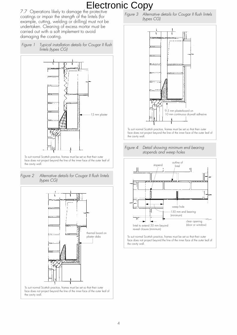
7.7 Operations likely to damage the protectivecoatings or impair the strength of the lintels (forexample, cutting, welding or drilling) must not beundertaken. Cleaning of excess mortar must becarried out with a soft implement to avoiddamaging the coating.
Figure 1 Typical installation details for Cougar II flushlintels (types CG)
Figure 2 Alternative details for Cougar II flush lintels(types CG)
Figure 3 Alternative details for Cougar II flush lintels(types CG)
Figure 4 Detail showing minimum end bearingstopends and weep holes
4
Electronic Copy

Technical Investigations
The following is a summary of the technicalinvestigations carried out on Catnic Cougar IIRange of Cavity Wall Lintels.
8 Tests
As part of the assessment resulting in the issue ofthe previous Certificates, tests were carried out toestablish:
(1) load deflection characteristics of CatnicCougar II Cavity Wall Lintels
(2) fire resistance of selected lintel profiles toBS 476-1 : 1953 and BS 476-8 : 1972
(3) thickness and quality of galvanizing andepoxy and polyester resin coatings
(4) resistance to damage of the epoxy andpolyester resin coatings.
9 Other investigations
9.1 As part of the assessment resulting in the issueof the previous Certificate, the followinginvestigations were made:
(1) Calculations were undertaken, and examinedin conjunction with the results of the load-deflectiontests referred to in section 8(1) to establish structuralperformance.
(2) Existing information relating to the suitability ofthe corrosion protection was examined, includingresults of long-term exposure tests on galvanizedsteel carried out by the British Steel Corporation.
(3) Data relating to the effectiveness of the lintelsas damp-proof trays and their effect on theweathertightness of cavity walls were alsoexamined.
9.2 Calculations were undertaken to determine:(1) the U value in accordance with CIBSE Guide1986 : Part A3 Thermal properties of buildingstructures, and
(2) condensation risk.
9.3 The results of the tests carried out undersection 8(1) were examined in conjunction withthese calculations.
9.4 From existing data an assessment was madeof:behaviour in firepracticability of installation.
9.5 The manufacturing process was examined,including the methods adopted for quality control,and details were obtained of the quality andcomposition of the materials used.
9.6 As part of the assessment resulting in the issueof this Certificate, the following investigations weremade:(1) A re-examination was made of the data andinvestigations on which the previous Certificate wasbased. The conclusions drawn from the originaldata remain valid.
(2) Tests were carried out on Catnic Cougar IICavity Wall Lintels to establish load deflectioncharacteristics.
(3) Calculations were undertaken on CatnicCougar II Cavity Wall Lintels and examined inconjunction with the results of the load/deflectiontests referred to above, to establish structuralperformance.
(4) Suitability of the corrosion resistance of thestainless steel.
9.7 Regular factory inspections have been carriedout to ensure that quality is being maintained.
9.8 Failure of the product in use has not beenreported to the BBA.
5
Electronic Copy

Bibliography
BS 476 Fire tests on building materials andstructuresBS 476-1 : 1953 Fire tests on building materialsand structuresBS 476-8 : 1972 Test methods and criteria for thefire resistance of elements of building construction
BS 5216 : 1991 Specification for patented colddrawn steel wire for mechanical springs
BS 5250 : 1989(1995) Code of practice forcontrol of condensation in buildings
BS 5628 Code of practice for use of masonryBS 5628-1 : 1992 Structural use of unreinforcedmasonryBS 5628-3 : 1985 Materials and components,design and workmanship
BS 5977 LintelsBS 5977-1 : 1981(1986) Method for assessmentof loadBS 5977-2 : 1983 Specification for prefabricatedlintels
On behalf of the British Board of Agrément
Date of issue: 27th March 2002 Chief Executive
British Board of AgrémentP O Box No 195, Bucknalls LaneGarston, Watford, Herts WD25 9BAFax: 01923 665301
©2002 For technical or additionalinformation, tel: 01923 665300.For information about AgrémentCertificate validity and scope, tel:Hotline: 01923 665400
e-mail: [email protected]: www.bbacerts.co.uk
Electronic Copy